Embed Size (px)
Citation preview
Application Note
Contents Introduction ................................................................................................................... 2
Outline of Transmit On/Off Power Measurement ...................................................... 3
Issues at TX On/Off Power Measurement ................................................................... 4
Solving Tradeoffs: Wide Dynamic Range Function ..................................................... 6
Issue of Previous Methods and its solution: Extended Noise Cancellation ........... 7
Stable Measurements with High Level Accuracy up to 6 GHz using MS269xA Series 8
Summary ........................................................................................................................ 8
Appendix A: Example of Transmit On/Off Power Measurement (Wide Dynamic Range) ............................................................................................................................. 9
Appendix B: Example of Transmit On/Off Power Measurement in Limiter Mode (Expansion Noise Cancel) ............................................................................................ 10
LTE TDD Base Station Transmit On/Off Power Measurement Signal Analyzer MS2690A/MS2691A/MS2692A LTE TDD Downlink Measurement Software MX269022A

2
Introduction The TDD system offering good frequency usage efficiency is being used increasingly to solve problems with securing sufficient spectrum bandwidth supporting the explosive increases in mobile traffic. Against this background, the relatively high frequency band between 2 GHz and 3.8 GHz is seeing increased usage. Due to the high linearity of radio waves in this frequency band, so-called small cells offering coverage over and narrow range using low output are being used increasingly as base stations. On the other hand, since radio waves are often obstructed by the geography of the service area as well as structures—such as buildings—within it, combinations of macrocells and small cells offering the best user experience are being designed for service areas. Since TDD systems use the same frequencies for both downlinks and uplinks, they have an advantage of good frequency usage efficiency, but on the other hand, if the timeslot synchronization accuracy and the power control during the transmit Off period are inadequate, there is a risk of interference between the downlink and uplink. To prevent this problem, section 6.4 of the 3GPP TS36.141 standard defines the transmit On/Off power with the intention of securing base signal station quality. This standard specifies the downlink signal transition timing as well as the power during the transmoit Off period. This measurement requires extremely high dynamic range as well as a low noise floor and cannot be performed by the normal measurement methods even using currently available high-performance signal analyzers. This document explains transmit On/Off power measurements of LTE TDD base stations using the Anritsu Signal Analyzer MS269xA series running the LTE TDD Downlink Measurement Software MX269022A to solve such measurement problems. <Notations in this document> Measured value: This is not a guaranteed specification. It means a measurement for a MS269xA set chosen at random from a production lot.

3
Outline of Transmit On/Off Power Measurement The minimum requirements for measuring transmit On/Off power defined in section 6.4 of the 3GPP TS36.141 Standard are shown below.
・ The average power density during the transmit Off period must be less than -85 dBm/MHz+[TT]. ・ The transition time (transmitter transient period) between the transmitter off and on, and on and
off periods, must be less than 17 µs.
Fig. 1 Diagram of Transmit On/Off Power Measurement (extract from 3GPP TS36.141 standard)
The transmit power is measured as the average power passing the filter during the 70-µs period. This measurement period is from the [On period + 17 µs + 35 µs] until the [Next On period – 17 µs –35 µs]. The specified values must be satisfied during this measurement period.
Fig. 2 Average Power During Transmit On Period (Horizontal Red Line)
Transmitter Output Power
Time
Transmitter ON period (DL Subframe and DwPTS)
Transmitter OFF period
Transmitter OFF period
Transmitter transient period
OFF power level
ON power level (Informative)
4
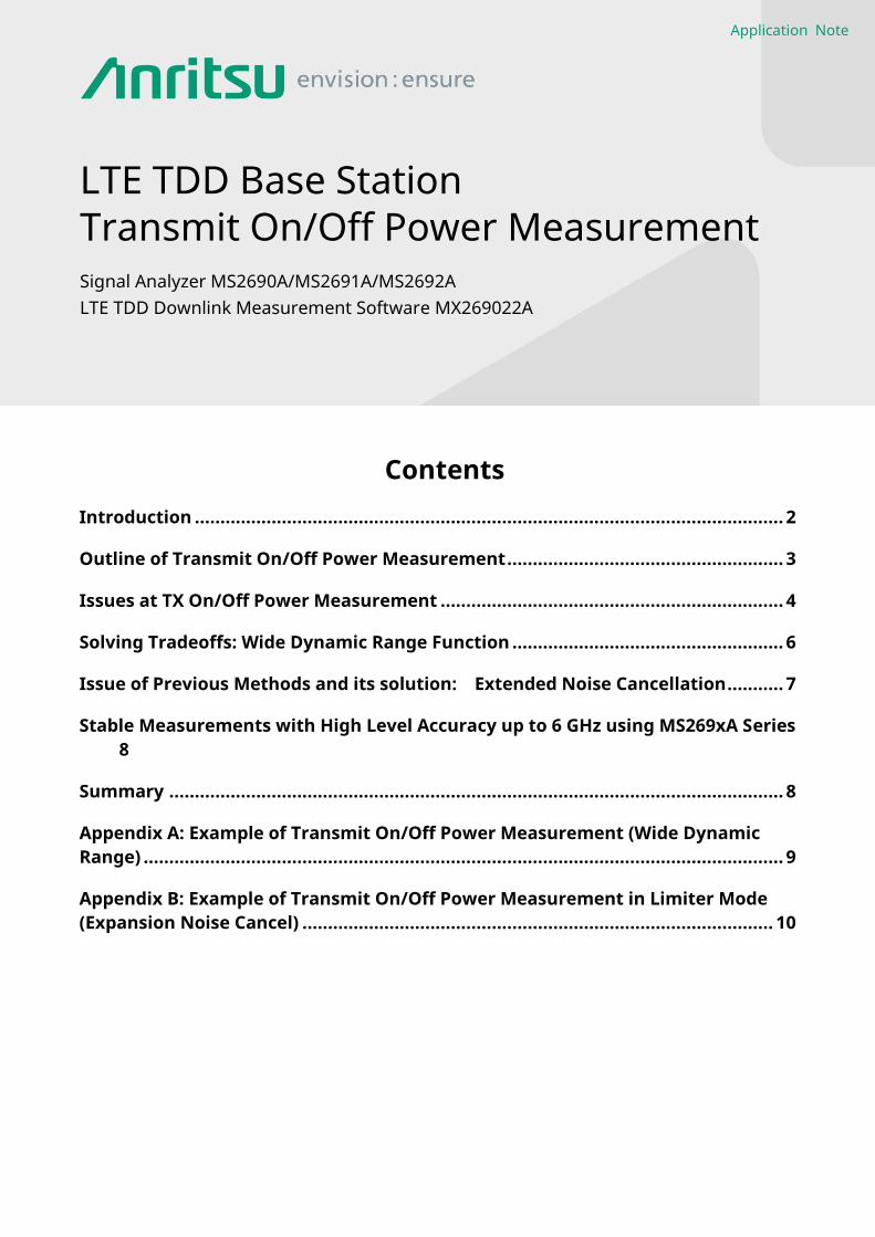
The MX269022A software measures the transient periods as follows:
Transition from transmit On to transmit Off Period (Ramp down): This is the period from the end of the Downlink Subframe based on the Frame Header until the point where the power falls below the transmit Off power threshold value.
Transition from transmit Off to transmit On Period (Ramp up): This is the period from the point where the power rises above the transmit Off power threshold value until the start of the next Downlink Subframe based on the Frame Header.
Transmit Off power threshold value described above is set at [Measure]>[F2] Power vs. Time > [F6] Mask Setup > [F5] Off Power Limit in the M26902A software.
One slot,
Tslot=15360Ts
GPUpPT
SDwPTS
One radio frame, Tf = 307200Ts = 10 ms
One half-frame, 153600Ts = 5 ms
30720Ts
One
subframe,
30720Ts
GPUpPT
SDwPTS
Subframe #2 Subframe #3 Subframe #4Subframe #0 Subframe #5 Subframe #7 Subframe #8 Subframe #9
Fig. 3 LTE TDD Time Frame Structure (extract from 3GPP TS36.211)
Table 1 LTE TDD Uplink-Downlink Configuration (extract from 3GPP TS36.211)
Uplink-Downlink configuration
Downlink-to-Uplink Switch-Point Periodicity
Subframe Number 0 1 2 3 4 5 6 7 8 9
0 5 ms D S U U U D S U U U 1 5 ms D S U U D D S U U D 2 5 ms D S U D D D S U D D 3 10 ms D S U U U D D D D D 4 10 ms D S U U D D D D D D 5 10 ms D S U D D D D D D D 6 5 ms D S U U U D S U U D
Issues at TX On/Off Power Measurement Figure 4 shows the system when measuring common burst signals. The signal transmitted from the DUT suffers both On and Off power losses caused by losses at the measurement system attenuators, switches, cables, etc., and noise floor increases. At this time, if the attenuated transmit Off power approaches the internal noise floor of the signal analyzer, the signal analyzer is unable to accurately measure the transmit Off power.

5
Fig. 4 General Model of Transmit On/Off Power Measurement
The following methods are generally used to increase the transmit Off power above the noise floor. Minimize the measurement system loss and attenuators to reduce Off power attenuation. Use low-noise amplifiers (LNA) in the measurement system and use a pre-amplifier in the signal analyzer to
amplify the Off power above the noise floor. Use the signal analyzer noise cancelling function to remove the noise floor from the calculation. However, the above-described methods have the following tradeoffs. Reducing the measurement system loss, or in other words reducing attenuation at the front end of the signal
analyzer, can cause the power at transmit On to exceed the maximum permissible input to the signal analyzer, risking damage to it.
Inserting an LNA and pre-amp requires consideration of the maximum permissible inputs for such devices. The amount of signal analyzer noise cancellation can impact the input signal status and the amount may be
limited. The reason why LTE TDD transmit On/Off power measurement is difficult is because both a high power at transmit On and a low power at transmit Off must be input continuously to the signal analyzer. When measuring the transmit On power, it is necessary to insert an external attenuator to ensure that the input signal to the signal analyzer does not exceed the maximum permissible input level, but this can cause problems when measuring low power. For example, when using a signal analyzer where the maximum mixer input level is +30 dBm at CW, for an LTE base station rated for an average power per antenna of +46 dBm, the measured transmit Off power will be around –85 dBm/MHz. If the LTE signal Crest Factor (peak to average power ratio) is 14 dB, the LTE base station transmit signal peak power will be +46 dBm + 14 dB = +60 dBm. To prevent this LTE signal input to the signal analyzer exceeding the maximum permissible input, a +30 dB attenuator must be inserted at the front stage of the signal analyzer. Doing so not only attenuates the transmit On power but also attenuates the transmit Off power which becomes -85 + -30 = -115 dB/MHz. Converting this value to power per Hz gives a value of -175 dBm/Hz, which cannot be measured even using a high-level signal analyzer.

6
Solving Tradeoffs: Wide Dynamic Range Function To solve this tradeoff, the MX269022A has a Wide Dynamic Range function that can offer a wide dynamic range covering the combined result of measuring the transmit On and transmit Off powers separately (Fig. 5). When measuring the transmit On power, the value of the signal analyzer built-in attenuator is set to the best value so the transmit On power does not cause distortion at measurement. If the base station transmit On power exceeds the maximum permissible input value of the signal analyzer, insert an external attenuator. With this measurement system and settings, there is a risk that the transmit Off power will be buried under the internal noise floor of the signal analyzer, but this is not a problem because the signal analyzer automatically extracts the result from the transmit On power result. When measuring the transmit Off power, the system loss and signal analyzer internal attenuator amount are set to the minimum to minimize the attenuation of the transmit Off power. If the dynamic range is insufficient, either the pre-amp or Noise Cancel function is enabled. Measurement of the transmit On power under these conditions risks inaccurate measurement due to the impact of distortion and saturation, but it is not a problem because the signal analyzer automatically extracts the result from the transmit Off power result. The signal analyzer determines the Frame header from either the LTE sync signal or an external trigger, and evaluates which are the transmit On and Off periods according to the set Uplink/Downlink Configuration and Special Subframe Configuration to set the best internal parameters matching the periods automatically and perform the measurement. The MX269022A displays the transmit On/Off transition time for one Frame period, the average On power, and the average Off power all on one screen. When measuring with the MS269xA Wide Dynamic Range and pre-amp functions enabled, since the average display noise level specification in the 3.5 GHz band is –161.5 dBm/Hz, it is –101.5 dBm/Hz. So, there is a margin of about 21.5 –(measurement system loss) dB versus the 3GPP test requirement of -85.0 + [TT](2.5) = -82.5 dBm/MHz. (When not using the Limiter Mode described below, the dynamic range is widened by enabling the pre-amp instead of using the Noise Cancel function.
Time Fig. 5 Expanding Dynamic Range and Reducing Noise Floor using Wide Dynamic Range Function
Refer to Appendix A for the transmit On/Off power measurement procedure using the MX269022A Wide Dynamic Range function.
Red Line: Tx ON power (first measurement) Blue Line: Tx OFF power (second measurement) Black Line: Waveform after combining Dotted Line: Unused measured data

7
Issue of Previous Methods and its solution: Extended Noise Cancellation
The quality of the LTE TDD base station downlink transmit Off power not only has a direct impact on the uplink communications quality but since there is also a risk of impact on connected systems, sometimes different regions and service operators set stricter standards than the 3GPP specifications. For example, for a macrocell base station with a transmit On power of +46 dBm (40 W) per antenna, measurement may require setting the transmit Off power to -107 dBm/MHz. The MS269xA has excellent noise-floor performance and using the MX269022A Wide Dynamic Range and pre-amp functions with cancellation of the signal analyzer internal noise enables noise floor measured values of about -110 dBm/MHz(meas. @3.5 GHz, ATT = 0 dB). Consequently, at a transmit Off power of -107 dBm/MHz, the measurement margin when connecting the antenna connector and signal analyzer with cables having a loss of only 0.5 dB/meter is -107 - 0.5 -(-110) = 2.5 dB. On the other hand, since the transmit On power is +46 dBm, to prevent damaging the MS269xA by exceeding the maximum input level of +30 dBm, it is necessary to insert some form of external device to attenuate the power. Although the difference is 16 dB, an attenuator cannot be used because there is already a margin of only 2.5 dB. Consequently, the power above a fixed amount is cut using a so-called power limiter that allows power below this value to pass with minimum loss. Anritsu recommends using the Aeroflex ACLM-4905 power limiter for measuring 3.5-GHz band LTE TDD base stations. The ACLM-4905 has a leak level of about +13 dBm so the MS269xA with pre-amp can be used for actual measurements. When the power limiter passthrough loss is about 1 dB, the measurement margin is 2.5-1.0 = 1.5 dB. (The power limiter can be connected to either end of the cable.) Even among signal analyzers currently on the market with high-level noise-floor performance, the measurement margin is still only 1.5 dB, making actual usage extremely difficult. First, the measurement environment with a configuration using a 1-meter cable connection between the base station and signal analyzer is very restrictive. Second, measuring the transmit Off power by inserting a power limiter and then removing the power limiter and inserting an attenuator for the transmit On power measurement not only greatly reduces the efficiency of the measurement procedure but also increases the number of unstable elements from the viewpoint of measurement reproducibility. As a consequence, the performance of previous signal analyzers does not support the stricter test requirements. As a result, Anritsu is introducing the concept of a unique extended noise cancellation function as a measurement solution supporting these types of stricter test requirements. This concept extends the previous noise cancellation function targeting only the internal noise of the signal analyzer to also cancel the noise of the external measurement system as well. Figure 6 shows the composition of a general measurement system for measuring transmit On power with extended noise cancellation. The LNA inserted upstream of the signal analyzer amplifies the transmit Off power. Although inserting the LNA increases the interference noise floor, if the noise floor is measured before the transmit Off power measurement by terminating the LNA input, a wider dynamic range can be achieved by using noise cancellation processing to subtract that value from the transmit Off power measurement result.
Fig. 6 Transmit Off Power Measurement System using Extended Noise Cancellation
The extended noise cancellation function supports the strict transmit Off power measurement test requirements. Figure 6 shows the block diagram for a transmit On/Off power measurement jig using the extended noise cancellation function. The paths for transmit Off and On measurement are switched by switches to assure the measurement margin; the measurement efficiency is high because the procedure can be simplified and automated.

8
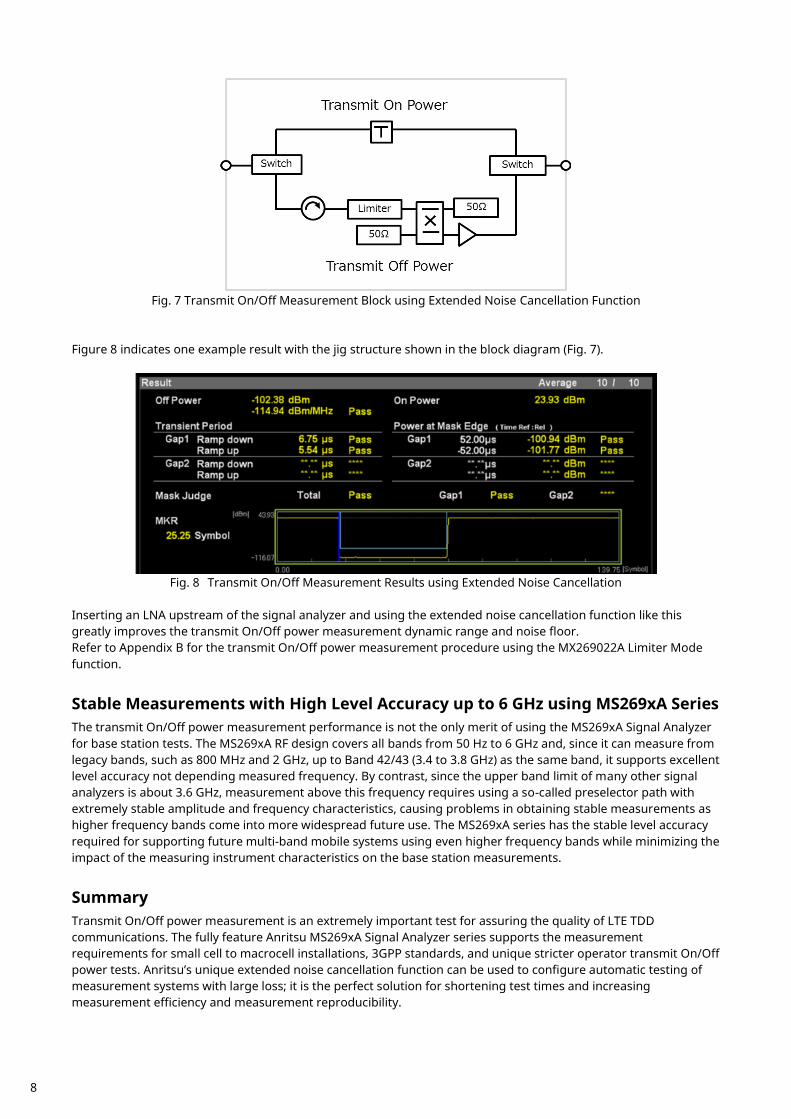
Fig. 7 Transmit On/Off Measurement Block using Extended Noise Cancellation Function
Figure 8 indicates one example result with the jig structure shown in the block diagram (Fig. 7).
Fig. 8 Transmit On/Off Measurement Results using Extended Noise Cancellation
Inserting an LNA upstream of the signal analyzer and using the extended noise cancellation function like this greatly improves the transmit On/Off power measurement dynamic range and noise floor. Refer to Appendix B for the transmit On/Off power measurement procedure using the MX269022A Limiter Mode function.
Stable Measurements with High Level Accuracy up to 6 GHz using MS269xA Series The transmit On/Off power measurement performance is not the only merit of using the MS269xA Signal Analyzer for base station tests. The MS269xA RF design covers all bands from 50 Hz to 6 GHz and, since it can measure from legacy bands, such as 800 MHz and 2 GHz, up to Band 42/43 (3.4 to 3.8 GHz) as the same band, it supports excellent level accuracy not depending measured frequency. By contrast, since the upper band limit of many other signal analyzers is about 3.6 GHz, measurement above this frequency requires using a so-called preselector path with extremely stable amplitude and frequency characteristics, causing problems in obtaining stable measurements as higher frequency bands come into more widespread future use. The MS269xA series has the stable level accuracy required for supporting future multi-band mobile systems using even higher frequency bands while minimizing the impact of the measuring instrument characteristics on the base station measurements.
Summary Transmit On/Off power measurement is an extremely important test for assuring the quality of LTE TDD communications. The fully feature Anritsu MS269xA Signal Analyzer series supports the measurement requirements for small cell to macrocell installations, 3GPP standards, and unique stricter operator transmit On/Off power tests. Anritsu’s unique extended noise cancellation function can be used to configure automatic testing of measurement systems with large loss; it is the perfect solution for shortening test times and increasing measurement efficiency and measurement reproducibility.
9
Appendix A:
Example of Transmit On/Off Power Measurement (Wide Dynamic Range) <Setup> Stop the base station transmitting. Connect the Frame signal for a 10-ms interval from the base station to the signal analyzer trigger input
connector. Connect the base station antenna connector and signal analyzer RF input connector. Select the MX269022A LTE TDD Downlink Measurement Software (default).
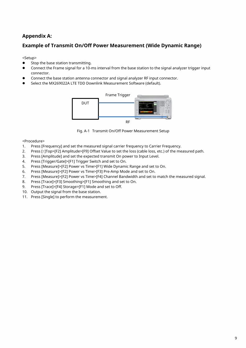
Fig. A-1 Transmit On/Off Power Measurement Setup
<Procedure> 1. Press [Frequency] and set the measured signal carrier frequency to Carrier Frequency. 2. Press [↑]Top>[F2] Amplitude>[F9] Offset Value to set the loss (cable loss, etc.) of the measured path. 3. Press [Amplitude] and set the expected transmit On power to Input Level. 4. Press [Trigger/Gate]>[F1] Trigger Switch and set to On. 5. Press [Measure]>[F2] Power vs Time>[F1] Wide Dynamic Range and set to On. 6. Press [Measure]>[F2] Power vs Time>[F3] Pre-Amp Mode and set to On. 7. Press [Measure]>[F2] Power vs Time>[F4] Channel Bandwidth and set to match the measured signal. 8. Press [Trace]>[F3] Smoothing>[F1] Smoothing and set to On. 9. Press [Trace]>[F4] Storage>[F1] Mode and set to Off. 10. Output the signal from the base station. 11. Press [Single] to perform the measurement.
DUT
Frame Trigger
RF

10
Appendix B:
Example of Transmit On/Off Power Measurement in Limiter Mode
(Expansion Noise Cancel) <Setup> Stop the base station transmitting. Connect the Frame signal for 10 milliseconds interval from the base station to the signal analyzer trigger input
connector. Connect the base station antenna to the signal analyzer RF input. Select the MX269022A LTE TDD Downlink Measurement Software in the signal analyzer.
Fig. B-1 Noise Measurement Path
Fig. B-2 Transmit Off Power Measurement Path
Fig. B-3 Transmit On Power Measurement Path
<Procedure> 1. Press [Frequency] and set the measured signal carrier frequency to Carrier Frequency. 2. Press [↑]Top>[F2] Amplitude>[F9] Offset Value to set the loss of the transmit On power (attenuator, cable loss,
etc.) path in Fig. B-3. 3. Press [Amplitude] and set the expected transmit On power to Input Level. 4. Press [Trigger/Gate]>[F1] Trigger Switch and set to On. 5. Press [Measure]>[F2] Power vs Time>[F1] Wide Dynamic Range and set to On. 6. Press [Measure]>[F2] Power vs Time>[F8] Limiter Mode and set to On. 7. Press [F3] Limiter Mode Offset to set On.
RF
LNA
DUT
Frame Trigger
RF
LNA Limiter
DUT
Frame Trigger
RF
ATT

11
8. Press [F4] Limiter Mode Offset Value to set the gain of the transmit Off power path in Fig. B-2 (from DUT output connector to signal analyzer RF input connector). For a total gain of 10 dB, set –10 dB.
9. Press [Measure]>[F2] Power vs Time>[F2] Noise Correction to set On. 10. Press [Measure]>[F2] Power vs Time>[F3] Pre-Amp Mode to set On. 11. Press [Measure]>[F2] Power vs Time>[F4] Channel Bandwidth and set to match the measured signal. 12. Press [Trace]>[F3] Smoothing>[F1] Smoothing to set On. 13. Press [Trace]>[F4] Storage>[F1] Mode to set Off. 14. Press [Single] to start measurement. 15. Set the noise measurement path in Fig. B-1. 16. Press [F1] Continue to measure the noise floor including the external LNA. 17. Set the transmit Off power measurement path shown in Fig. B-2. 18. Output the signal from the base station. 19. Press [F1] Continue to measure the transmit Off power. 20. Stop signal output from the base station. 21. Set the transmit On power measurement path shown in Fig. B-3. 22. Output the signal from the base station. 23. Press [F1] Continue to measure the transmit On power.

12
Note

8
Fig. 7 Transmit On/Off Measurement Block using Extended Noise Cancellation Function
Figure 8 indicates one example result with the jig structure shown in the block diagram (Fig. 7).
Fig. 8 Transmit On/Off Measurement Results using Extended Noise Cancellation
Inserting an LNA upstream of the signal analyzer and using the extended noise cancellation function like this greatly improves the transmit On/Off power measurement dynamic range and noise floor. Refer to Appendix B for the transmit On/Off power measurement procedure using the MX269022A Limiter Mode function.
Stable Measurements with High Level Accuracy up to 6 GHz using MS269xA Series The transmit On/Off power measurement performance is not the only merit of using the MS269xA Signal Analyzer for base station tests. The MS269xA RF design covers all bands from 50 Hz to 6 GHz and, since it can measure from legacy bands, such as 800 MHz and 2 GHz, up to Band 42/43 (3.4 to 3.8 GHz) as the same band, it supports excellent level accuracy not depending measured frequency. By contrast, since the upper band limit of many other signal analyzers is about 3.6 GHz, measurement above this frequency requires using a so-called preselector path with extremely stable amplitude and frequency characteristics, causing problems in obtaining stable measurements as higher frequency bands come into more widespread future use. The MS269xA series has the stable level accuracy required for supporting future multi-band mobile systems using even higher frequency bands while minimizing the impact of the measuring instrument characteristics on the base station measurements.
Summary Transmit On/Off power measurement is an extremely important test for assuring the quality of LTE TDD communications. The fully feature Anritsu MS269xA Signal Analyzer series supports the measurement requirements for small cell to macrocell installations, 3GPP standards, and unique stricter operator transmit On/Off power tests. Anritsu’s unique extended noise cancellation function can be used to configure automatic testing of measurement systems with large loss; it is the perfect solution for shortening test times and increasing measurement efficiency and measurement reproducibility.

9
Appendix A:
Example of Transmit On/Off Power Measurement (Wide Dynamic Range) <Setup> Stop the base station transmitting. Connect the Frame signal for a 10-ms interval from the base station to the signal analyzer trigger input
connector. Connect the base station antenna connector and signal analyzer RF input connector. Select the MX269022A LTE TDD Downlink Measurement Software (default).
Fig. A-1 Transmit On/Off Power Measurement Setup
<Procedure> 1. Press [Frequency] and set the measured signal carrier frequency to Carrier Frequency. 2. Press [↑]Top>[F2] Amplitude>[F9] Offset Value to set the loss (cable loss, etc.) of the measured path. 3. Press [Amplitude] and set the expected transmit On power to Input Level. 4. Press [Trigger/Gate]>[F1] Trigger Switch and set to On. 5. Press [Measure]>[F2] Power vs Time>[F1] Wide Dynamic Range and set to On. 6. Press [Measure]>[F2] Power vs Time>[F3] Pre-Amp Mode and set to On. 7. Press [Measure]>[F2] Power vs Time>[F4] Channel Bandwidth and set to match the measured signal. 8. Press [Trace]>[F3] Smoothing>[F1] Smoothing and set to On. 9. Press [Trace]>[F4] Storage>[F1] Mode and set to Off. 10. Output the signal from the base station. 11. Press [Single] to perform the measurement.
DUT
Frame Trigger
RF

10
Appendix B:
Example of Transmit On/Off Power Measurement in Limiter Mode
(Expansion Noise Cancel) <Setup> Stop the base station transmitting. Connect the Frame signal for 10 milliseconds interval from the base station to the signal analyzer trigger input
connector. Connect the base station antenna to the signal analyzer RF input. Select the MX269022A LTE TDD Downlink Measurement Software in the signal analyzer.
Fig. B-1 Noise Measurement Path
Fig. B-2 Transmit Off Power Measurement Path
Fig. B-3 Transmit On Power Measurement Path
<Procedure> 1. Press [Frequency] and set the measured signal carrier frequency to Carrier Frequency. 2. Press [↑]Top>[F2] Amplitude>[F9] Offset Value to set the loss of the transmit On power (attenuator, cable loss,
etc.) path in Fig. B-3. 3. Press [Amplitude] and set the expected transmit On power to Input Level. 4. Press [Trigger/Gate]>[F1] Trigger Switch and set to On. 5. Press [Measure]>[F2] Power vs Time>[F1] Wide Dynamic Range and set to On. 6. Press [Measure]>[F2] Power vs Time>[F8] Limiter Mode and set to On. 7. Press [F3] Limiter Mode Offset to set On.
RF
LNA
DUT
Frame Trigger
RF
LNA Limiter
DUT
Frame Trigger
RF
ATT

11
8. Press [F4] Limiter Mode Offset Value to set the gain of the transmit Off power path in Fig. B-2 (from DUT output connector to signal analyzer RF input connector). For a total gain of 10 dB, set –10 dB.
9. Press [Measure]>[F2] Power vs Time>[F2] Noise Correction to set On. 10. Press [Measure]>[F2] Power vs Time>[F3] Pre-Amp Mode to set On. 11. Press [Measure]>[F2] Power vs Time>[F4] Channel Bandwidth and set to match the measured signal. 12. Press [Trace]>[F3] Smoothing>[F1] Smoothing to set On. 13. Press [Trace]>[F4] Storage>[F1] Mode to set Off. 14. Press [Single] to start measurement. 15. Set the noise measurement path in Fig. B-1. 16. Press [F1] Continue to measure the noise floor including the external LNA. 17. Set the transmit Off power measurement path shown in Fig. B-2. 18. Output the signal from the base station. 19. Press [F1] Continue to measure the transmit Off power. 20. Stop signal output from the base station. 21. Set the transmit On power measurement path shown in Fig. B-3. 22. Output the signal from the base station. 23. Press [F1] Continue to measure the transmit On power.

Anritsu Company 1155 East Collins Blvd., Suite 100, Richardson, TX 75081, U.S.A.Toll Free: 1-800-267-4878Phone: +1-972-644-1777Fax: +1-972-671-1877
• CanadaAnritsu Electronics Ltd.700 Silver Seven Road, Suite 120, Kanata, Ontario K2V 1C3, CanadaPhone: +1-613-591-2003 Fax: +1-613-591-1006
• Brazil Anritsu Eletrônica Ltda.Praça Amadeu Amaral, 27 - 1 Andar01327-010 - Bela Vista - São Paulo - SP - BrazilPhone: +55-11-3283-2511Fax: +55-11-3288-6940
• MexicoAnritsu Company, S.A. de C.V.Av. Ejército Nacional No. 579 Piso 9, Col. Granada11520 México, D.F., MéxicoPhone: +52-55-1101-2370Fax: +52-55-5254-3147
• United KingdomAnritsu EMEA Ltd. 200 Capability Green, Luton, Bedfordshire, LU1 3LU, U.K.Phone: +44-1582-433200 Fax: +44-1582-731303
• FranceAnritsu S.A. 12 avenue du Québec, Bâtiment Iris 1- Silic 612,91140 VILLEBON SUR YVETTE, FrancePhone: +33-1-60-92-15-50Fax: +33-1-64-46-10-65
• GermanyAnritsu GmbHNemetschek Haus, Konrad-Zuse-Platz 1 81829 München, Germany Phone: +49-89-442308-0Fax: +49-89-442308-55
• ItalyAnritsu S.r.l.Via Elio Vittorini 129, 00144 Roma, ItalyPhone: +39-6-509-9711 Fax: +39-6-502-2425
• SwedenAnritsu ABKistagången 20B, 164 40 KISTA, SwedenPhone: +46-8-534-707-00Fax: +46-8-534-707-30
• FinlandAnritsu ABTeknobulevardi 3-5, FI-01530 VANTAA, FinlandPhone: +358-20-741-8100Fax: +358-20-741-8111
• DenmarkAnritsu A/SKay Fiskers Plads 9, 2300 Copenhagen S, DenmarkPhone: +45-7211-2200Fax: +45-7211-2210
• RussiaAnritsu EMEA Ltd. Representation Office in RussiaTverskaya str. 16/2, bld. 1, 7th floor.Moscow, 125009, RussiaPhone: +7-495-363-1694Fax: +7-495-935-8962
• SpainAnritsu EMEA Ltd. Representation Office in SpainEdificio Cuzco IV, Po. de la Castellana, 141, Pta. 828046, Madrid, SpainPhone: +34-915-726-761Fax: +34-915-726-621
• United Arab EmiratesAnritsu EMEA Ltd. Dubai Liaison OfficeP O Box 500413 - Dubai Internet CityAl Thuraya Building, Tower 1, Suit 701, 7th FloorDubai, United Arab EmiratesPhone: +971-4-3670352Fax: +971-4-3688460
• P.R. China (Shanghai)Anritsu (China) Co., Ltd.Room 2701-2705, Tower A, New Caohejing International Business CenterNo. 391 Gui Ping Road Shanghai, 200233, P.R. ChinaPhone: +86-21-6237-0898Fax: +86-21-6237-0899
• P.R. China (Hong Kong)Anritsu Company Ltd.Unit 1006-7, 10/F., Greenfield Tower, Concordia Plaza,No. 1 Science Museum Road, Tsim Sha Tsui East, Kowloon, Hong Kong, P.R. ChinaPhone: +852-2301-4980Fax: +852-2301-3545
• JapanAnritsu Corporation8-5, Tamura-cho, Atsugi-shi, Kanagawa, 243-0016 JapanPhone: +81-46-296-1221Fax: +81-46-296-1238
• KoreaAnritsu Corporation, Ltd.5FL, 235 Pangyoyeok-ro, Bundang-gu, Seongnam-si, Gyeonggi-do, 463-400 KoreaPhone: +82-31-696-7750Fax: +82-31-696-7751
• AustraliaAnritsu Pty. Ltd.Unit 21/270 Ferntree Gully Road, Notting Hill, Victoria 3168, AustraliaPhone: +61-3-9558-8177Fax: +61-3-9558-8255
• TaiwanAnritsu Company Inc.7F, No. 316, Sec. 1, NeiHu Rd., Taipei 114, TaiwanPhone: +886-2-8751-1816Fax: +886-2-8751-1817
1506
Printed on Recycled Paper
• SingaporeAnritsu Pte. Ltd.11 Chang Charn Road, #04-01, Shriro HouseSingapore 159640Phone: +65-6282-2400Fax: +65-6282-2533
• IndiaAnritsu India Private Limited2nd & 3rd Floor, #837/1, Binnamangla 1st Stage,Indiranagar, 100ft Road, Bangalore - 560038, IndiaPhone: +91-80-4058-1300Fax: +91-80-4058-1301
Specifications are subject to change without notice.
• United States
Printed in Japan 2015-8 MG No. MS269xA-E-F-9-(1.00)