Embed Size (px)
Citation preview
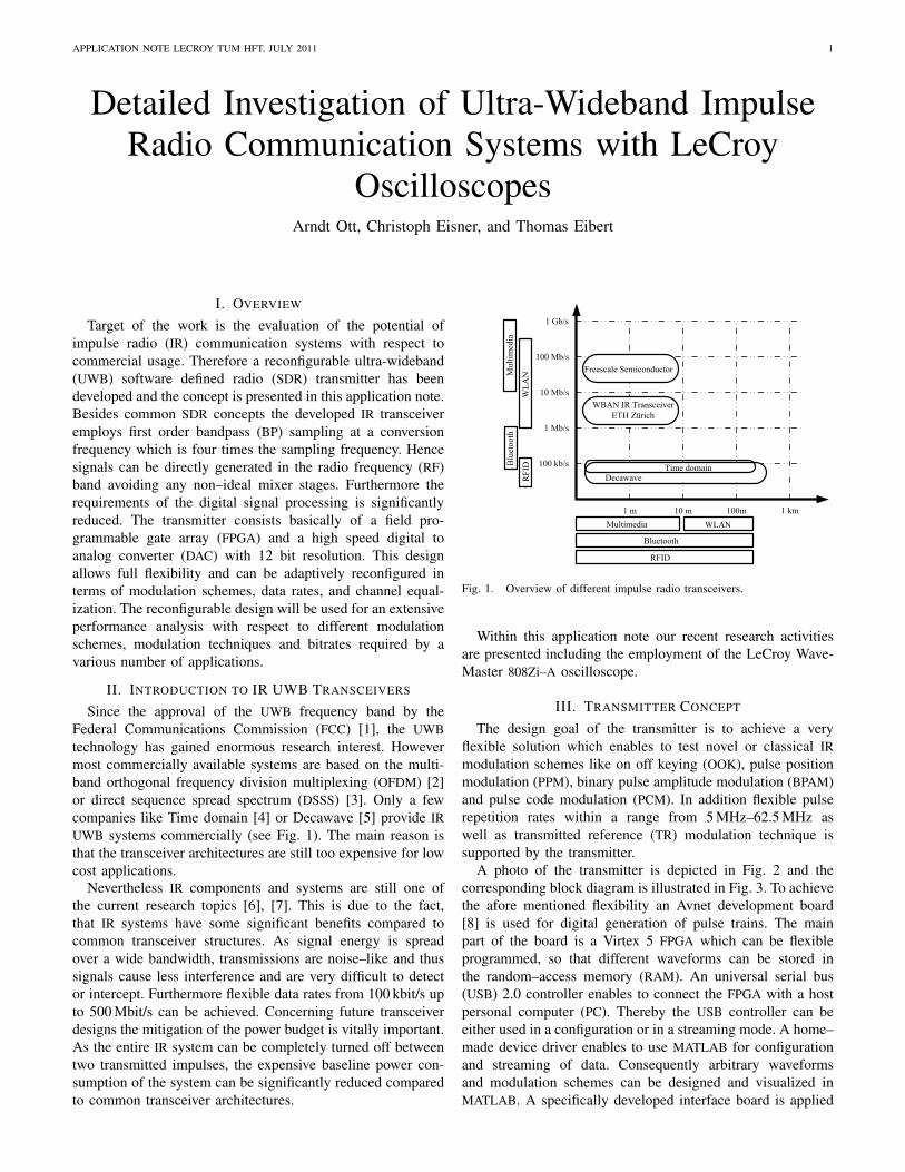
APPLICATION NOTE LECROY TUM HFT, JULY 2011 1
Detailed Investigation of Ultra-Wideband ImpulseRadio Communication Systems with LeCroy
OscilloscopesArndt Ott, Christoph Eisner, and Thomas Eibert
I. OVERVIEW
Target of the work is the evaluation of the potential ofimpulse radio (IR) communication systems with respect tocommercial usage. Therefore a reconfigurable ultra-wideband(UWB) software defined radio (SDR) transmitter has beendeveloped and the concept is presented in this application note.Besides common SDR concepts the developed IR transceiveremploys first order bandpass (BP) sampling at a conversionfrequency which is four times the sampling frequency. Hencesignals can be directly generated in the radio frequency (RF)band avoiding any non–ideal mixer stages. Furthermore therequirements of the digital signal processing is significantlyreduced. The transmitter consists basically of a field pro-grammable gate array (FPGA) and a high speed digital toanalog converter (DAC) with 12 bit resolution. This designallows full flexibility and can be adaptively reconfigured interms of modulation schemes, data rates, and channel equal-ization. The reconfigurable design will be used for an extensiveperformance analysis with respect to different modulationschemes, modulation techniques and bitrates required by avarious number of applications.
II. INTRODUCTION TO IR UWB TRANSCEIVERS
Since the approval of the UWB frequency band by theFederal Communications Commission (FCC) [1], the UWBtechnology has gained enormous research interest. Howevermost commercially available systems are based on the multi-band orthogonal frequency division multiplexing (OFDM) [2]or direct sequence spread spectrum (DSSS) [3]. Only a fewcompanies like Time domain [4] or Decawave [5] provide IRUWB systems commercially (see Fig. 1). The main reason isthat the transceiver architectures are still too expensive for lowcost applications.
Nevertheless IR components and systems are still one ofthe current research topics [6], [7]. This is due to the fact,that IR systems have some significant benefits compared tocommon transceiver structures. As signal energy is spreadover a wide bandwidth, transmissions are noise–like and thussignals cause less interference and are very difficult to detector intercept. Furthermore flexible data rates from 100 kbit/s upto 500 Mbit/s can be achieved. Concerning future transceiverdesigns the mitigation of the power budget is vitally important.As the entire IR system can be completely turned off betweentwo transmitted impulses, the expensive baseline power con-sumption of the system can be significantly reduced comparedto common transceiver architectures.
1 Gb/s
100 Mb/s
1 Mb/s
10 Mb/s
100 kb/s
1 m 10 m 100m 1 km
WBAN IR Transceiver
ETH Zürich
Freescale Semiconductor
DecawaveTime domain
Mu
ltim
edia
WL
AN
Blu
eto
oth
RF
IDMultimedia WLAN
RFID
Bluetooth
Fig. 1. Overview of different impulse radio transceivers.
Within this application note our recent research activitiesare presented including the employment of the LeCroy Wave-Master 808Zi–A oscilloscope.
III. TRANSMITTER CONCEPT
The design goal of the transmitter is to achieve a veryflexible solution which enables to test novel or classical IRmodulation schemes like on off keying (OOK), pulse positionmodulation (PPM), binary pulse amplitude modulation (BPAM)and pulse code modulation (PCM). In addition flexible pulserepetition rates within a range from 5 MHz–62.5 MHz aswell as transmitted reference (TR) modulation technique issupported by the transmitter.
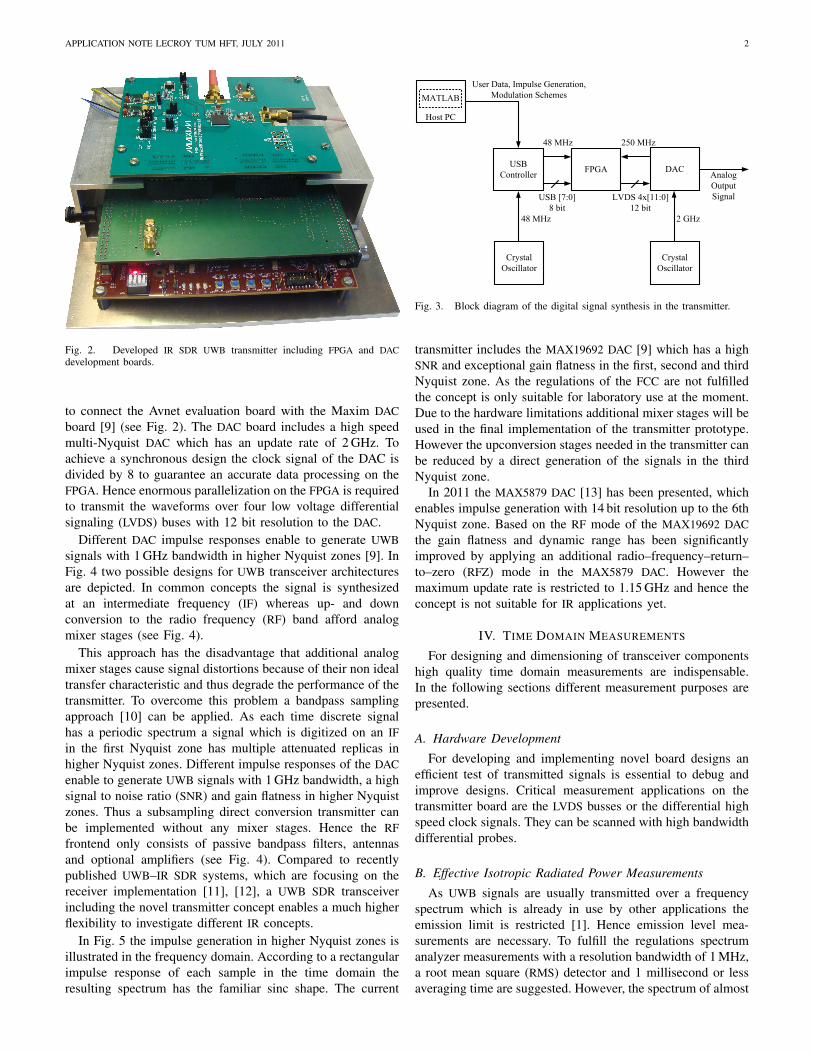
A photo of the transmitter is depicted in Fig. 2 and thecorresponding block diagram is illustrated in Fig. 3. To achievethe afore mentioned flexibility an Avnet development board[8] is used for digital generation of pulse trains. The mainpart of the board is a Virtex 5 FPGA which can be flexibleprogrammed, so that different waveforms can be stored inthe random–access memory (RAM). An universal serial bus(USB) 2.0 controller enables to connect the FPGA with a hostpersonal computer (PC). Thereby the USB controller can beeither used in a configuration or in a streaming mode. A home–made device driver enables to use MATLAB for configurationand streaming of data. Consequently arbitrary waveformsand modulation schemes can be designed and visualized inMATLAB. A specifically developed interface board is applied
APPLICATION NOTE LECROY TUM HFT, JULY 2011 2
Fig. 2. Developed IR SDR UWB transmitter including FPGA and DACdevelopment boards.
to connect the Avnet evaluation board with the Maxim DACboard [9] (see Fig. 2). The DAC board includes a high speedmulti-Nyquist DAC which has an update rate of 2 GHz. Toachieve a synchronous design the clock signal of the DAC isdivided by 8 to guarantee an accurate data processing on theFPGA. Hence enormous parallelization on the FPGA is requiredto transmit the waveforms over four low voltage differentialsignaling (LVDS) buses with 12 bit resolution to the DAC.
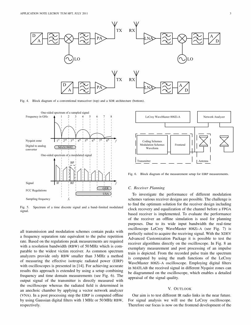
Different DAC impulse responses enable to generate UWBsignals with 1 GHz bandwidth in higher Nyquist zones [9]. InFig. 4 two possible designs for UWB transceiver architecturesare depicted. In common concepts the signal is synthesizedat an intermediate frequency (IF) whereas up- and downconversion to the radio frequency (RF) band afford analogmixer stages (see Fig. 4).
This approach has the disadvantage that additional analogmixer stages cause signal distortions because of their non idealtransfer characteristic and thus degrade the performance of thetransmitter. To overcome this problem a bandpass samplingapproach [10] can be applied. As each time discrete signalhas a periodic spectrum a signal which is digitized on an IFin the first Nyquist zone has multiple attenuated replicas inhigher Nyquist zones. Different impulse responses of the DACenable to generate UWB signals with 1 GHz bandwidth, a highsignal to noise ratio (SNR) and gain flatness in higher Nyquistzones. Thus a subsampling direct conversion transmitter canbe implemented without any mixer stages. Hence the RFfrontend only consists of passive bandpass filters, antennasand optional amplifiers (see Fig. 4). Compared to recentlypublished UWB–IR SDR systems, which are focusing on thereceiver implementation [11], [12], a UWB SDR transceiverincluding the novel transmitter concept enables a much higherflexibility to investigate different IR concepts.
In Fig. 5 the impulse generation in higher Nyquist zones isillustrated in the frequency domain. According to a rectangularimpulse response of each sample in the time domain theresulting spectrum has the familiar sinc shape. The current
FPGAUSB
Controller
Host PC
DAC
Crystal
Oscillator
Crystal
Oscillator
Analog
Output
SignalLVDS 4x[11:0]
12 bit
USB [7:0]
8 bit
48 MHz 2 GHz
MATLAB
250 MHz48 MHz
User Data, Impulse Generation,
Modulation Schemes
Fig. 3. Block diagram of the digital signal synthesis in the transmitter.
transmitter includes the MAX19692 DAC [9] which has a highSNR and exceptional gain flatness in the first, second and thirdNyquist zone. As the regulations of the FCC are not fulfilledthe concept is only suitable for laboratory use at the moment.Due to the hardware limitations additional mixer stages will beused in the final implementation of the transmitter prototype.However the upconversion stages needed in the transmitter canbe reduced by a direct generation of the signals in the thirdNyquist zone.
In 2011 the MAX5879 DAC [13] has been presented, whichenables impulse generation with 14 bit resolution up to the 6thNyquist zone. Based on the RF mode of the MAX19692 DACthe gain flatness and dynamic range has been significantlyimproved by applying an additional radio–frequency–return–to–zero (RFZ) mode in the MAX5879 DAC. However themaximum update rate is restricted to 1.15 GHz and hence theconcept is not suitable for IR applications yet.
IV. TIME DOMAIN MEASUREMENTS
For designing and dimensioning of transceiver componentshigh quality time domain measurements are indispensable.In the following sections different measurement purposes arepresented.
A. Hardware Development
For developing and implementing novel board designs anefficient test of transmitted signals is essential to debug andimprove designs. Critical measurement applications on thetransmitter board are the LVDS busses or the differential highspeed clock signals. They can be scanned with high bandwidthdifferential probes.
B. Effective Isotropic Radiated Power Measurements
As UWB signals are usually transmitted over a frequencyspectrum which is already in use by other applications theemission limit is restricted [1]. Hence emission level mea-surements are necessary. To fulfill the regulations spectrumanalyzer measurements with a resolution bandwidth of 1 MHz,a root mean square (RMS) detector and 1 millisecond or lessaveraging time are suggested. However, the spectrum of almost
APPLICATION NOTE LECROY TUM HFT, JULY 2011 3
D
A
LO
PA LNA
LO
DA
TX RX
D
APA LNA
DA
TX RX
Fig. 4. Block diagram of a conventional transceiver (top) and a SDR architecture (bottom).
1 2 876543
1st 8th7th6th5th4th3rd2nd
Frequency in GHz
Nyquist zone
Digital to analog
converter
IF RF
fs
f
f
One-sided spectrum of a sampled signal
GER
USA
Signal
FCC Regulations
Sampling frequency
BP
MAX19692
One-sided spectrum of a modulated signal
Fig. 5. Spectrum of a time discrete signal and a band–limited modulatedsignal.
all transmission and modulation schemes contain peaks witha frequency separation rate equivalent to the pulse repetitionrate. Based on the regulations peak measurements are requiredwith a resolution bandwidth (RBW) of 50 MHz which is com-parable to the widest victim receiver. As common spectrumanalyzers provide only RBW smaller than 3 MHz a methodof measuring the effective isotropic radiated power (EIRP)with oscilloscopes is presented in [14]. For achieving accurateresults this approach is extended by using a setup combiningfrequency and time domain measurements (see Fig. 6). Theoutput signal of the transmitter is directly measured withthe oscilloscope whereas the radiated field is determined inan anechoic chamber by applying a vector network analyzer(VNA). In a post processing step the EIRP is computed offlineby using Gaussian digital filters with 1 MHz or 50 MHz RBW,respectively.
Coding Schemes
Modulation Schemes
Waveform
LeCroy WaveMaster 808Zi-A
Frontend
Network Analyzer
Transmitter Antenna
Fig. 6. Block diagram of the measurement setup for EIRP measurements.
C. Receiver Planning
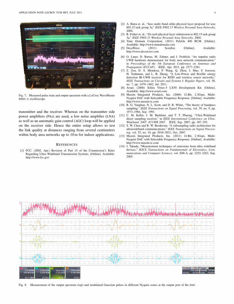
To investigate the performance of different modulationschemes various receiver designs are possible. The challenge isto find the optimum solution for the receiver design includingclock recovery and equalization of the channel before a FPGAbased receiver is implemented. To evaluate the performanceof the receiver an offline simulation is used for planningpurposes. Due to its wide input bandwidth the real-timeoscilloscope LeCroy WaveMaster 808Zi–A (see Fig. 7) isperfectly suited to acquire the receiving signal. With the XDEVAdvanced Customization Package it is possible to test thereceiver algorithms directly on the oscilloscope. In Fig. 8 anexemplary measurement and post processing of an impulsetrain is depicted. From the recorded pulse train the spectrumis computed by using the math functions of the LeCroyWaveMaster 808Zi–A oscilloscope. Employing digital filtersin MATLAB the received signal in different Nyquist zones canbe diagrammed on the oscilloscope, which enables a detailedappraisal of the signal quality.
V. OUTLOOK
Our aim is to test different IR radio links in the near future.For signal analysis we will use the LeCroy oscilloscope.Therefore our focus is now on the frontend development of the
APPLICATION NOTE LECROY TUM HFT, JULY 2011 4
Fig. 7. Measured pulse train and output spectrum with a LeCroy WaveMaster808Zi–A oscilloscope.
transmitter and the receiver. Whereas on the transmitter sidepower amplifiers (PAs) are used, a low noise amplifier (LNA)as well as an automatic gain control (AGC) loop will be appliedon the receiver side. Hence the entire setup allows to testthe link quality at distances ranging from several centimeterswithin body area networks up to 10 m for indoor applications.
REFERENCES
[1] FCC. (2002, Apr.) Revision of Part 15 of the Commission’s RulesRegarding Ultra–Wideband Transmission Systems. [Online]. Available:http://www.fcc.gov
[2] A. Batra et. al., “Ieee multi–band ofdm physical layer proposal for ieee802.15 task group 3a,” IEEE P802.15 Wireless Personal Area Networks,2004.
[3] R. Fisher et. al., “Ds-uwb physical layer submission to 802.15 task group3a,” IEEE P802.15 Wireless Personal Area Networks, 2004.
[4] Time Domain Corporation. (2011) PulsOn 400 RCM. [Online].Available: http://www.timedomain.com
[5] DecaWave. (2011) ScenSor. [Online]. Available:http://www.decawave.com
[6] O. Lauer, D. Barras, M. Zahner, and J. Frohlich, “An impulse radioUWB hardware demonstrator for body area network communication,”in Proceedings of the 5th European Conference on Antennas andPropagation (EUCAP). IEEE, Apr. 2011, pp. 2377–2381.
[7] Z. Zou, D. S. Mendoza, P. Wang, Q. Zhou, J. Mao, F. Jonsson,H. Tenhunen, and L. R. Zheng, “A Low-Power and flexible energydetection IR-UWB receiver for RFID and wireless sensor networks,”IEEE Transactions on Circuits and Systems I: Regular Papers, vol. 58,no. 7, pp. 1470–1482, Jul. 2011.
[8] Avnet. (2006) Xilinx Virtex-5 LX50 Development Kit. [Online].Available: http://www.avnet.com
[9] Maxim Integrated Products, Inc. (2006) 12-Bit, 2.3Gsps, Multi-Nyquist DAC with Selectable Frequency Response. [Online]. Available:http://www.maxim-ic.com
[10] R. G. Vaughan, N. L. Scott, and D. R. White, “The theory of bandpasssampling,” IEEE Transactions on Signal Processing, vol. 39, no. 9, pp.1973–1984, Sep. 1991.
[11] C. M. Keller, J. M. Burkhart, and T. T. Phuong, “Ultra-Widebanddirect sampling receiver,” in IEEE International Conference on Ultra-Wideband, 2007. ICUWB 2007. IEEE, Sep. 2007, pp. 387–392.
[12] S. W. Chen and R. W. Brodersen, “A subsampling radio architecture forultrawideband communications,” IEEE Transactions on Signal Process-ing, vol. 55, no. 10, pp. 5018–5031, Oct. 2007.
[13] Maxim Integrated Products, Inc. (2011) 14-Bit, 2.3Gsps, Multi-Nyquist DAC with Selectable Frequency Response. [Online]. Available:http://www.maxim-ic.com
[14] J. Takada, “Measurement techniques of emissions from ultra widebanddevices,” IEICE Transactions on Fundamentals of Electronics, Com-munications and Computer Sciences, vol. E88-A, pp. 2252–2263, Sep.2005.
Fig. 8. Measurement of the output spectrum (top) and modulated Gaussian pulses in different Nyquist zones at the output port of the DAC.