Embed Size (px)
Citation preview
1
Application Note: LC-1 / LM-1 to SCT’s Xcal 2
written by Steve Hulett
Disclaimer: Information in this document has not been verified.
Use at your own risk. Incorrectly Adjusting the Electronic fuel injection system can cause severe engine damage. The author assumes no liability for any damages associated with the use of this information.
2
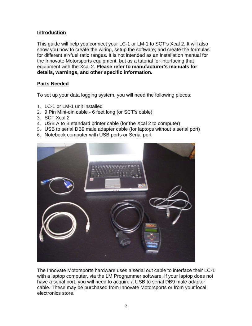
Introduction This guide will help you connect your LC-1 or LM-1 to SCT’s Xcal 2. It will also show you how to create the wiring, setup the software, and create the formulas for different air/fuel ratio ranges. It is not intended as an installation manual for the Innovate Motorsports equipment, but as a tutorial for interfacing that equipment with the Xcal 2. Please refer to manufacturer’s manuals for details, warnings, and other specific information. Parts Needed To set up your data logging system, you will need the following pieces: 1. LC-1 or LM-1 unit installed 2. 9 Pin Mini-din cable - 6 feet long (or SCT’s cable) 3. SCT Xcal 2 4. USB A to B standard printer cable (for the Xcal 2 to computer) 5. USB to serial DB9 male adapter cable (for laptops without a serial port) 6. Notebook computer with USB ports or Serial port
The Innovate Motorsports hardware uses a serial out cable to interface their LC-1 with a laptop computer, via the LM Programmer software. If your laptop does not have a serial port, you will need to acquire a USB to serial DB9 male adapter cable. These may be purchased from Innovate Motorsports or from your local electronics store.
3
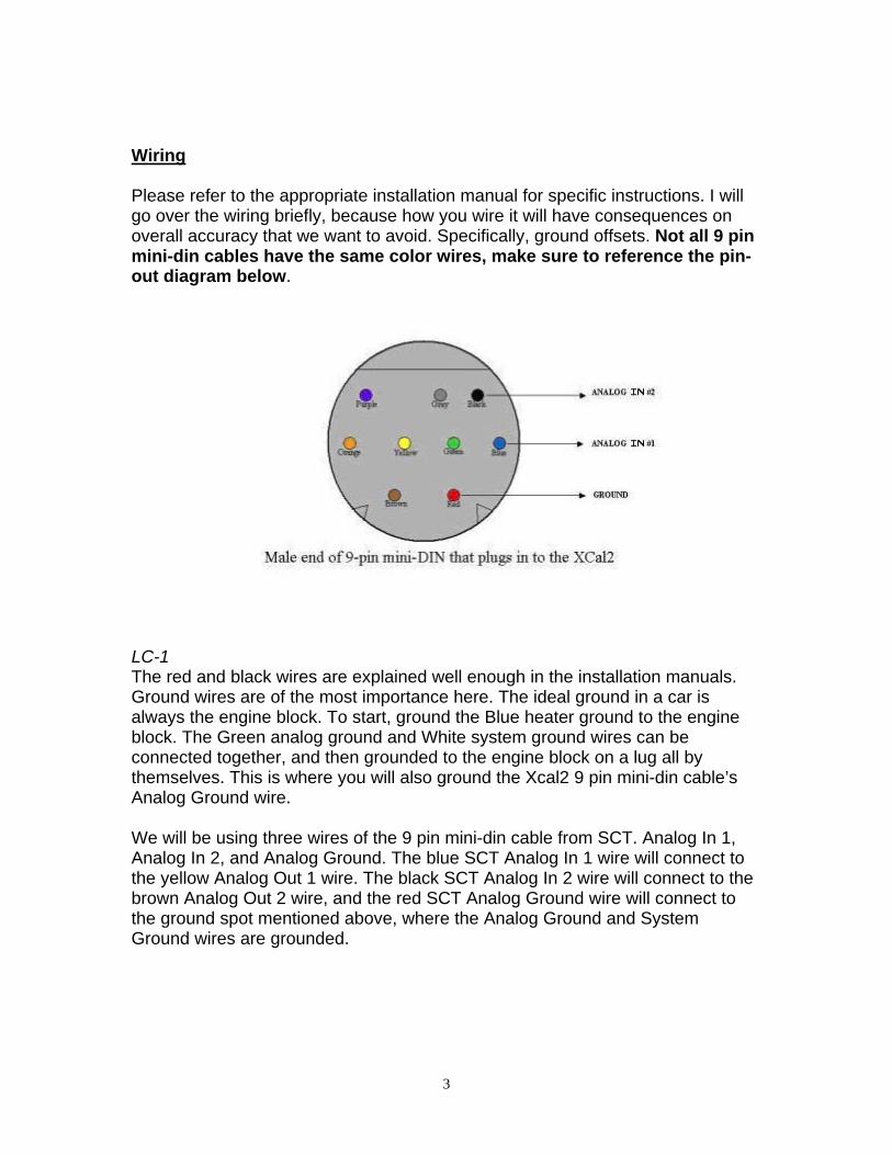
Wiring Please refer to the appropriate installation manual for specific instructions. I will go over the wiring briefly, because how you wire it will have consequences on overall accuracy that we want to avoid. Specifically, ground offsets. Not all 9 pin mini-din cables have the same color wires, make sure to reference the pin-out diagram below.
LC-1 The red and black wires are explained well enough in the installation manuals. Ground wires are of the most importance here. The ideal ground in a car is always the engine block. To start, ground the Blue heater ground to the engine block. The Green analog ground and White system ground wires can be connected together, and then grounded to the engine block on a lug all by themselves. This is where you will also ground the Xcal2 9 pin mini-din cable’s Analog Ground wire. We will be using three wires of the 9 pin mini-din cable from SCT. Analog In 1, Analog In 2, and Analog Ground. The blue SCT Analog In 1 wire will connect to the yellow Analog Out 1 wire. The black SCT Analog In 2 wire will connect to the brown Analog Out 2 wire, and the red SCT Analog Ground wire will connect to the ground spot mentioned above, where the Analog Ground and System Ground wires are grounded.
4
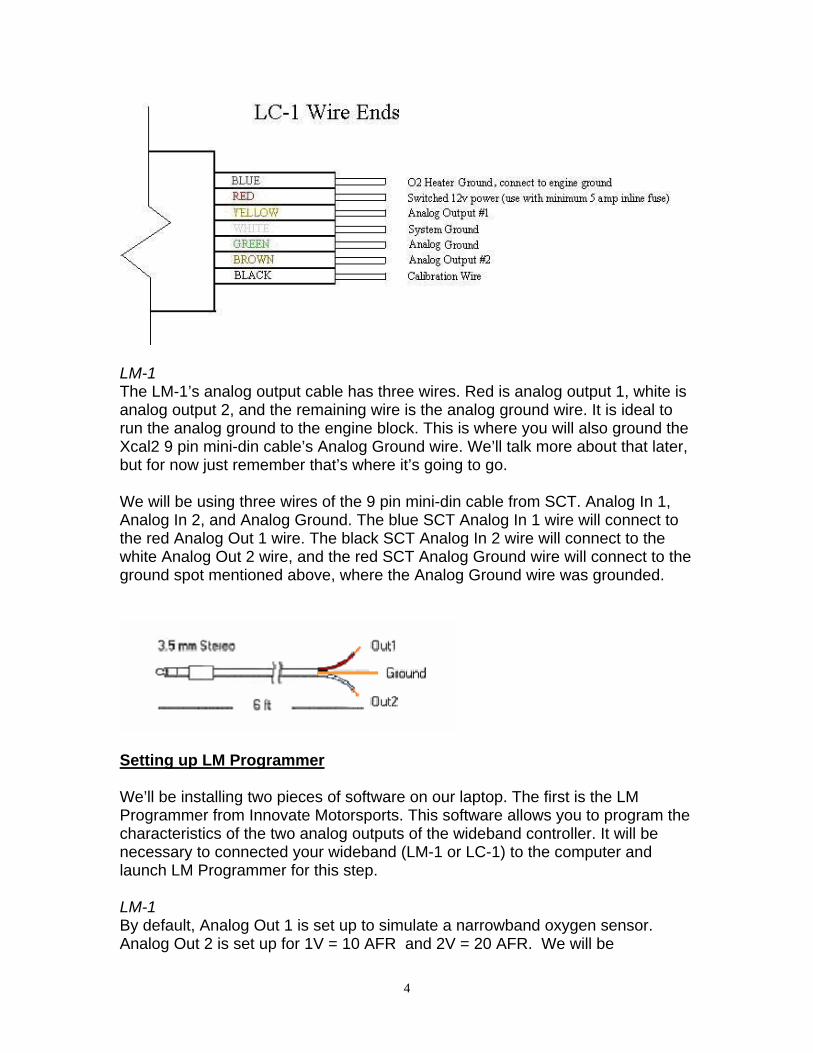
LM-1 The LM-1’s analog output cable has three wires. Red is analog output 1, white is analog output 2, and the remaining wire is the analog ground wire. It is ideal to run the analog ground to the engine block. This is where you will also ground the Xcal2 9 pin mini-din cable’s Analog Ground wire. We’ll talk more about that later, but for now just remember that’s where it’s going to go. We will be using three wires of the 9 pin mini-din cable from SCT. Analog In 1, Analog In 2, and Analog Ground. The blue SCT Analog In 1 wire will connect to the red Analog Out 1 wire. The black SCT Analog In 2 wire will connect to the white Analog Out 2 wire, and the red SCT Analog Ground wire will connect to the ground spot mentioned above, where the Analog Ground wire was grounded.
Setting up LM Programmer We’ll be installing two pieces of software on our laptop. The first is the LM Programmer from Innovate Motorsports. This software allows you to program the characteristics of the two analog outputs of the wideband controller. It will be necessary to connected your wideband (LM-1 or LC-1) to the computer and launch LM Programmer for this step. LM-1 By default, Analog Out 1 is set up to simulate a narrowband oxygen sensor. Analog Out 2 is set up for 1V = 10 AFR and 2V = 20 AFR. We will be
5
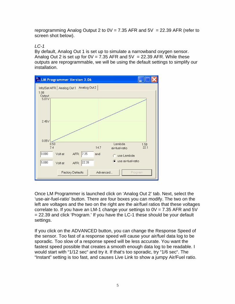
reprogramming Analog Output 2 to 0V = 7.35 AFR and 5V = 22.39 AFR (refer to screen shot below). LC-1 By default, Analog Out 1 is set up to simulate a narrowband oxygen sensor. Analog Out 2 is set up for 0V = 7.35 AFR and 5V = 22.39 AFR. While these outputs are reprogrammable, we will be using the default settings to simplify our installation.
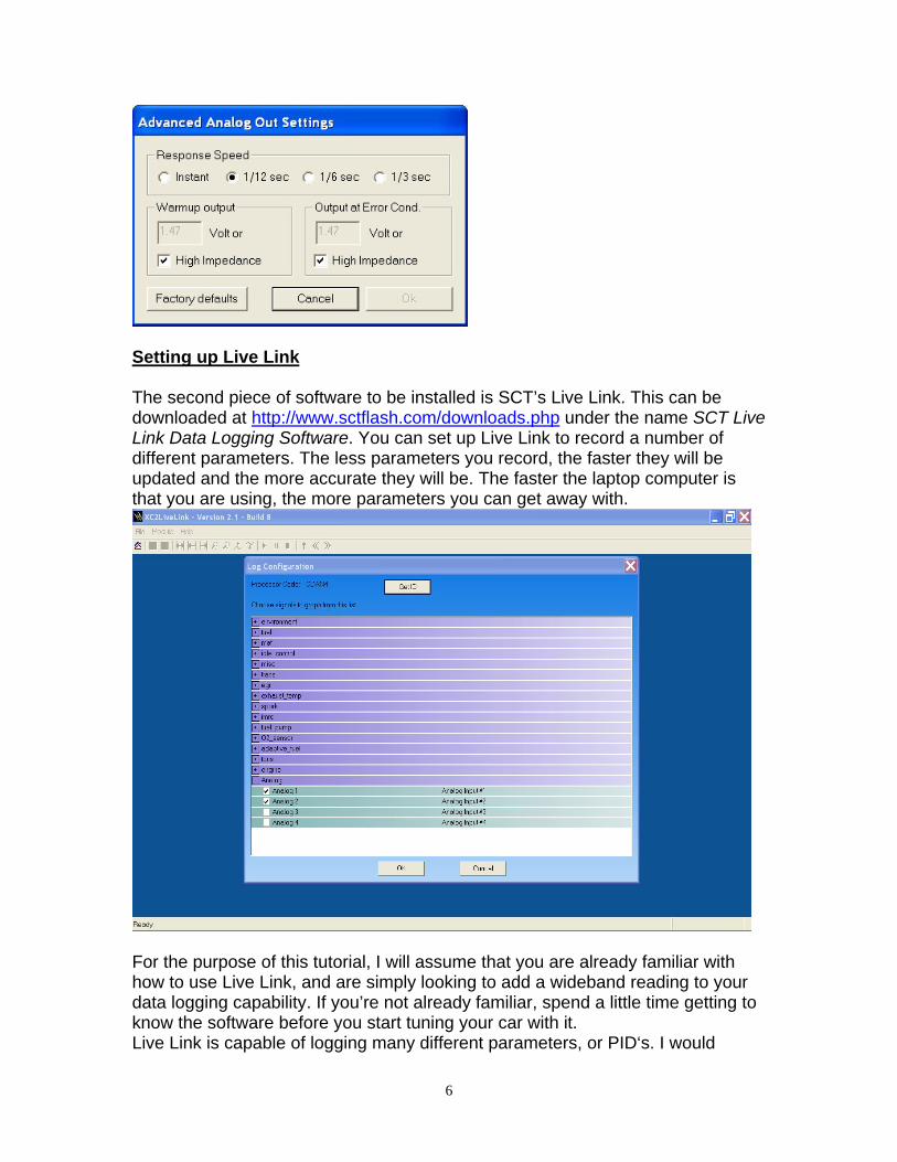
Once LM Programmer is launched click on ‘Analog Out 2’ tab. Next, select the ‘use-air-fuel-ratio’ button. There are four boxes you can modify. The two on the left are voltages and the two on the right are the air/fuel ratios that these voltages correlate to. If you have an LM-1 change your settings to 0V = 7.35 AFR and 5V = 22.39 and click ‘Program.’ If you have the LC-1 these should be your default settings. If you click on the ADVANCED button, you can change the Response Speed of the sensor. Too fast of a response speed will cause your air/fuel data log to be sporadic. Too slow of a response speed will be less accurate. You want the fastest speed possible that creates a smooth enough data log to be readable. I would start with “1/12 sec“ and try it. If that‘s too sporadic, try “1/6 sec“. The “Instant” setting is too fast, and causes Live Link to show a jumpy Air/Fuel ratio.
6
Setting up Live Link The second piece of software to be installed is SCT’s Live Link. This can be downloaded at http://www.sctflash.com/downloads.php under the name SCT Live Link Data Logging Software. You can set up Live Link to record a number of different parameters. The less parameters you record, the faster they will be updated and the more accurate they will be. The faster the laptop computer is that you are using, the more parameters you can get away with.
For the purpose of this tutorial, I will assume that you are already familiar with how to use Live Link, and are simply looking to add a wideband reading to your data logging capability. If you’re not already familiar, spend a little time getting to know the software before you start tuning your car with it. Live Link is capable of logging many different parameters, or PID‘s. I would
7
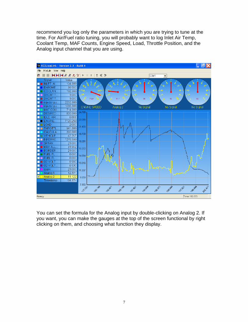
recommend you log only the parameters in which you are trying to tune at the time. For Air/Fuel ratio tuning, you will probably want to log Inlet Air Temp, Coolant Temp, MAF Counts, Engine Speed, Load, Throttle Position, and the Analog input channel that you are using.
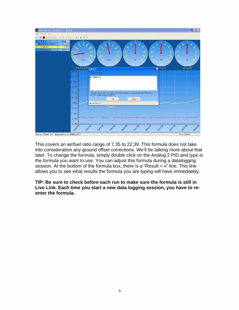
You can set the formula for the Analog input by double-clicking on Analog 2. If you want, you can make the gauges at the top of the screen functional by right clicking on them, and choosing what function they display.
8
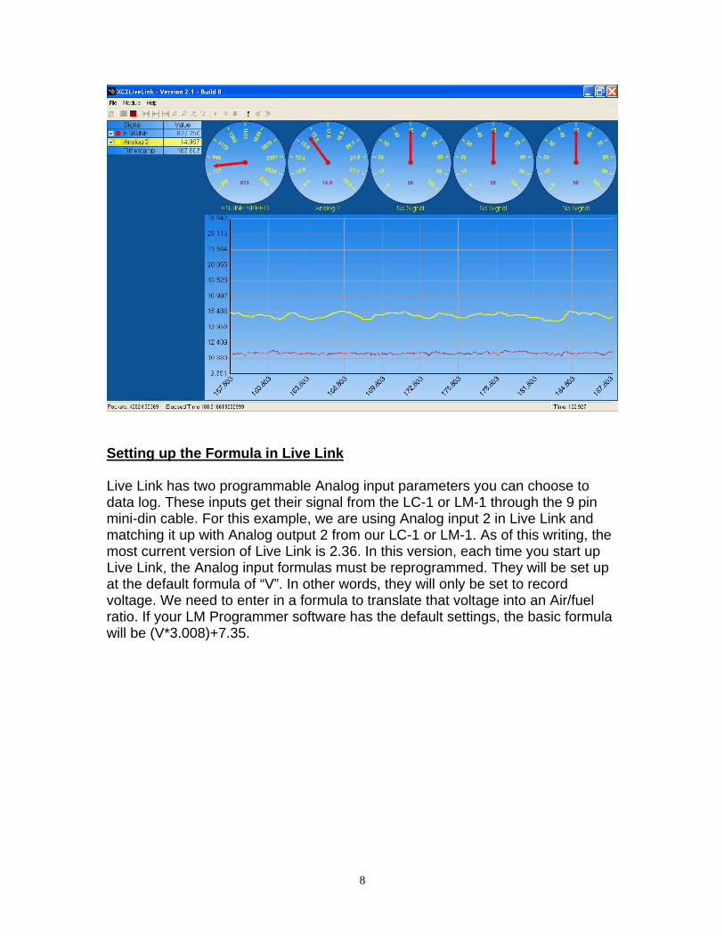
Setting up the Formula in Live Link Live Link has two programmable Analog input parameters you can choose to data log. These inputs get their signal from the LC-1 or LM-1 through the 9 pin mini-din cable. For this example, we are using Analog input 2 in Live Link and matching it up with Analog output 2 from our LC-1 or LM-1. As of this writing, the most current version of Live Link is 2.36. In this version, each time you start up Live Link, the Analog input formulas must be reprogrammed. They will be set up at the default formula of “V”. In other words, they will only be set to record voltage. We need to enter in a formula to translate that voltage into an Air/fuel ratio. If your LM Programmer software has the default settings, the basic formula will be (V*3.008)+7.35.
9
This covers an air/fuel ratio range of 7.35 to 22.39. This formula does not take into consideration any ground offset corrections. We’ll be talking more about that later. To change the formula, simply double click on the Analog 2 PID and type in the formula you want to use. You can adjust this formula during a datalogging session. At the bottom of the formula box, there is a “Result = x” line. This line allows you to see what results the formula you are typing will have immediately. TIP: Be sure to check before each run to make sure the formula is still in Live Link. Each time you start a new data logging session, you have to re-enter the formula.
10
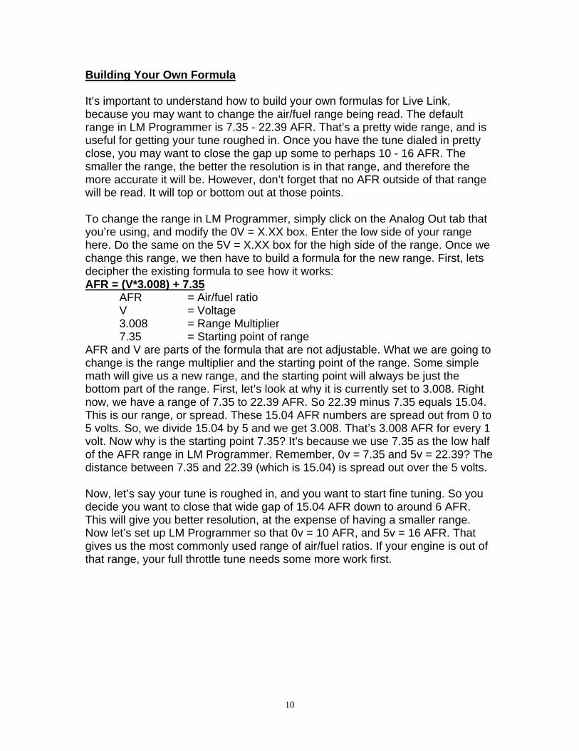
Building Your Own Formula It’s important to understand how to build your own formulas for Live Link, because you may want to change the air/fuel range being read. The default range in LM Programmer is 7.35 - 22.39 AFR. That’s a pretty wide range, and is useful for getting your tune roughed in. Once you have the tune dialed in pretty close, you may want to close the gap up some to perhaps 10 - 16 AFR. The smaller the range, the better the resolution is in that range, and therefore the more accurate it will be. However, don’t forget that no AFR outside of that range will be read. It will top or bottom out at those points. To change the range in LM Programmer, simply click on the Analog Out tab that you’re using, and modify the 0V = X.XX box. Enter the low side of your range here. Do the same on the 5V = X.XX box for the high side of the range. Once we change this range, we then have to build a formula for the new range. First, lets decipher the existing formula to see how it works: AFR = (V*3.008) + 7.35 AFR = Air/fuel ratio V = Voltage 3.008 = Range Multiplier 7.35 = Starting point of range AFR and V are parts of the formula that are not adjustable. What we are going to change is the range multiplier and the starting point of the range. Some simple math will give us a new range, and the starting point will always be just the bottom part of the range. First, let’s look at why it is currently set to 3.008. Right now, we have a range of 7.35 to 22.39 AFR. So 22.39 minus 7.35 equals 15.04. This is our range, or spread. These 15.04 AFR numbers are spread out from 0 to 5 volts. So, we divide 15.04 by 5 and we get 3.008. That’s 3.008 AFR for every 1 volt. Now why is the starting point 7.35? It’s because we use 7.35 as the low half of the AFR range in LM Programmer. Remember, 0v = 7.35 and 5v = 22.39? The distance between 7.35 and 22.39 (which is 15.04) is spread out over the 5 volts. Now, let’s say your tune is roughed in, and you want to start fine tuning. So you decide you want to close that wide gap of 15.04 AFR down to around 6 AFR. This will give you better resolution, at the expense of having a smaller range. Now let’s set up LM Programmer so that 0v = 10 AFR, and 5v = 16 AFR. That gives us the most commonly used range of air/fuel ratios. If your engine is out of that range, your full throttle tune needs some more work first.
11
Now, we’ve set up the output voltages in LM Programmer, so we need to create the new formula for Live Link to go with that. First, we find that the spread is 6 AFR (16 minus 10 equals 6). So we take 6 and divide it by the 5 volts, and we get 1.2. So our new formula will be (V*1.2)+10. The number 10 represents our new low side AFR (10 - 16 AFR range, remember?). When building a formula, the best thing to do is grab a calculator and make sure it works out. Let’s test our formula! OK, the car is at 16:1 AFR, the most lean for our range, so the LC-1 is going to be putting out a full 5 volts. So our formula would be (5*1.2)+10, which equates to (6)+10, which works out to be 16. Correct! That is the max lean AFR our formula allows. But what happens if the car is really at an air/fuel ratio of 9:1, or 18.5:1? Well, you’ve exceeded the narrow range that you allowed yourself (10 - 16 AFR), so the voltage will min or max out at 0 or 5v. In other words, 10 or 16 AFR. Again, the narrow range is more accurate, but at the expense of being narrower. TIP: The slight increase in accuracy is probably not worth having a narrow range. Ground Offsets A ground offset is a wiring problem that can change your air/fuel ratio readings, making them less accurate. This is a problem that should be tested for, minimized, and compensated for. What is a ground offset? Let’s say you have a positive wire that has 5 volts in it. That wire has to be grounded to complete the circuit. If you ground it to a really good ground (such as the engine block), it may
12
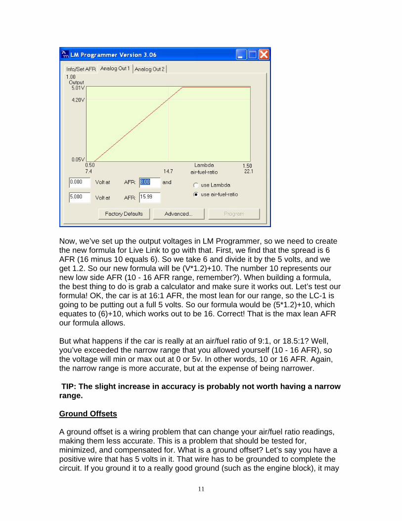
not have any offsets. If the ground you chose is shared by other wires, perhaps with even more voltage in them, your 5v wire will have trouble passing through that ground. This can reduce the voltage in your wire, for example, from 1.6v down to 1.52v (a .08v ground offset). Not a big difference. But let’s plug that into our formula and see just how big it is. (1.52*3.008)+7.35 = 11.92. We should have 12.16, so our ground offset has changed the air/fuel ratio by .24. That’s almost a quarter point of inaccuracy, leading you to believe the motor is richer than it really is! This is why we need to test for ground offsets. Here’s how… Set up LM Programmer to put out 0v = 2.5, and 5v = 2.5. This will cause the LC-1 to send out 2.5 volts no matter what the air/fuel ratio is. You can use different voltages for this test if you want, but don’t use voltages near the end of the spectrum like 0v or 5v. When you’re done entering in the voltages, you have to hit the “Program” button to program the LC-1 or LM-1 to use these settings.
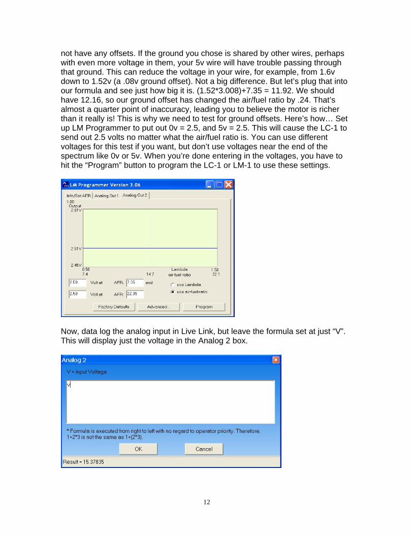
Now, data log the analog input in Live Link, but leave the formula set at just “V”. This will display just the voltage in the Analog 2 box.
13
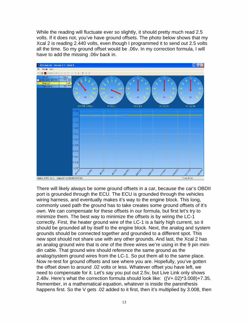
While the reading will fluctuate ever so slightly, it should pretty much read 2.5 volts. If it does not, you’ve have ground offsets. The photo below shows that my Xcal 2 is reading 2.440 volts, even though I programmed it to send out 2.5 volts all the time. So my ground offset would be .06v. In my correction formula, I will have to add the missing .06v back in.
There will likely always be some ground offsets in a car, because the car’s OBDII port is grounded through the ECU. The ECU is grounded through the vehicles wiring harness, and eventually makes it’s way to the engine block. This long, commonly used path the ground has to take creates some ground offsets of it’s own. We can compensate for these offsets in our formula, but first let’s try to minimize them. The best way to minimize the offsets is by wiring the LC-1 correctly. First, the heater ground wire of the LC-1 is a fairly high current, so it should be grounded all by itself to the engine block. Next, the analog and system grounds should be connected together and grounded to a different spot. This new spot should not share use with any other grounds. And last, the Xcal 2 has an analog ground wire that is one of the three wires we’re using in the 9 pin mini-din cable. That ground wire should reference the same ground as the analog/system ground wires from the LC-1. So put them all to the same place. Now re-test for ground offsets and see where you are. Hopefully, you’ve gotten the offset down to around .02 volts or less. Whatever offset you have left, we need to compensate for it. Let’s say you put out 2.5v, but Live Link only shows 2.48v. Here’s what the correction formula should look like: ((V+.02)*3.008)+7.35. Remember, in a mathematical equation, whatever is inside the parenthesis happens first. So the V gets .02 added to it first, then it’s multiplied by 3.008, then
14
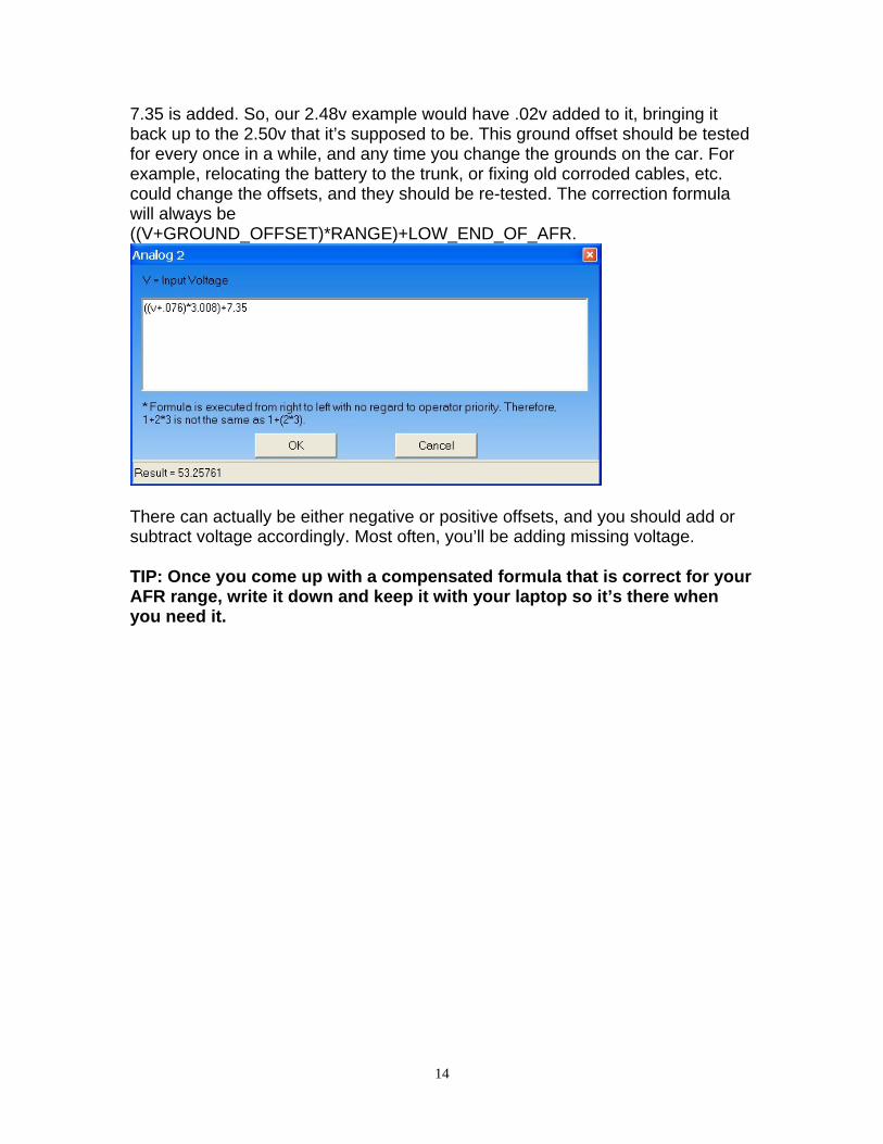
7.35 is added. So, our 2.48v example would have .02v added to it, bringing it back up to the 2.50v that it’s supposed to be. This ground offset should be tested for every once in a while, and any time you change the grounds on the car. For example, relocating the battery to the trunk, or fixing old corroded cables, etc. could change the offsets, and they should be re-tested. The correction formula will always be ((V+GROUND_OFFSET)*RANGE)+LOW_END_OF_AFR.
There can actually be either negative or positive offsets, and you should add or subtract voltage accordingly. Most often, you’ll be adding missing voltage. TIP: Once you come up with a compensated formula that is correct for your AFR range, write it down and keep it with your laptop so it’s there when you need it.
15
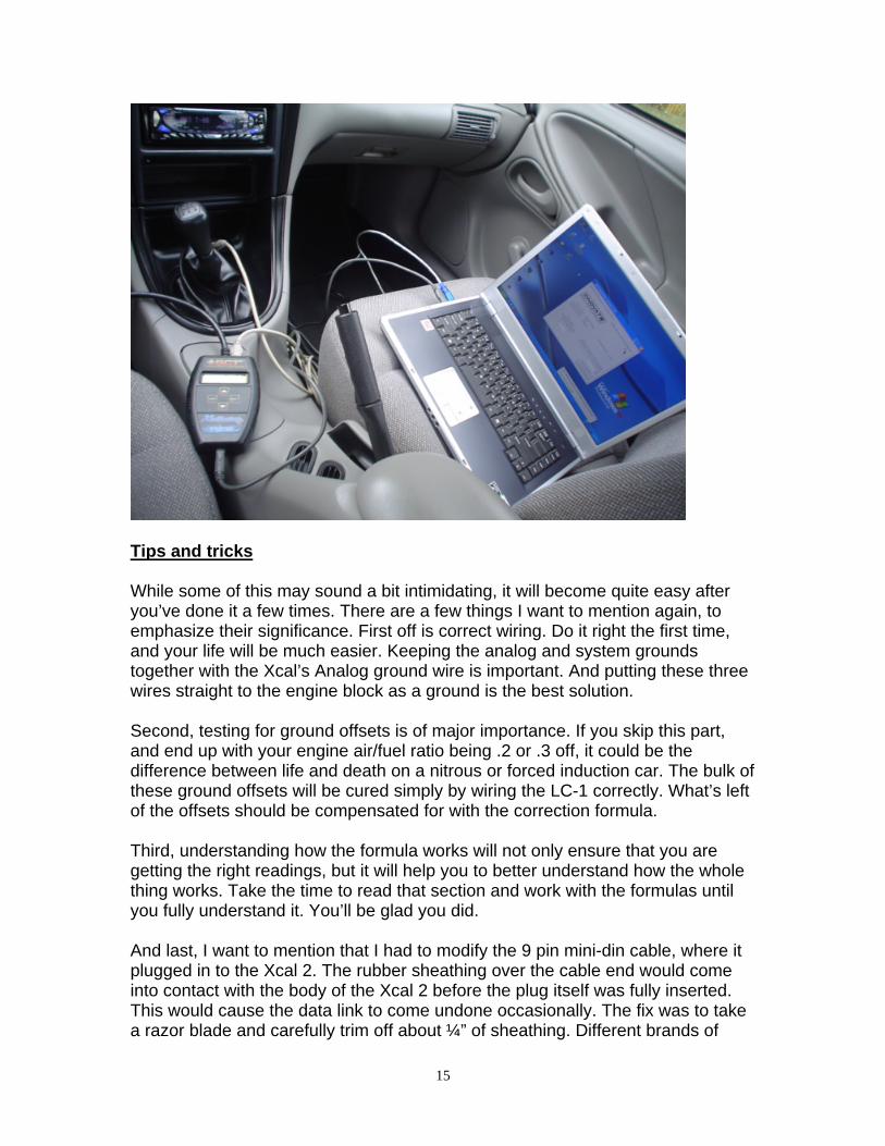
Tips and tricks While some of this may sound a bit intimidating, it will become quite easy after you’ve done it a few times. There are a few things I want to mention again, to emphasize their significance. First off is correct wiring. Do it right the first time, and your life will be much easier. Keeping the analog and system grounds together with the Xcal’s Analog ground wire is important. And putting these three wires straight to the engine block as a ground is the best solution. Second, testing for ground offsets is of major importance. If you skip this part, and end up with your engine air/fuel ratio being .2 or .3 off, it could be the difference between life and death on a nitrous or forced induction car. The bulk of these ground offsets will be cured simply by wiring the LC-1 correctly. What’s left of the offsets should be compensated for with the correction formula. Third, understanding how the formula works will not only ensure that you are getting the right readings, but it will help you to better understand how the whole thing works. Take the time to read that section and work with the formulas until you fully understand it. You’ll be glad you did. And last, I want to mention that I had to modify the 9 pin mini-din cable, where it plugged in to the Xcal 2. The rubber sheathing over the cable end would come into contact with the body of the Xcal 2 before the plug itself was fully inserted. This would cause the data link to come undone occasionally. The fix was to take a razor blade and carefully trim off about ¼” of sheathing. Different brands of
16
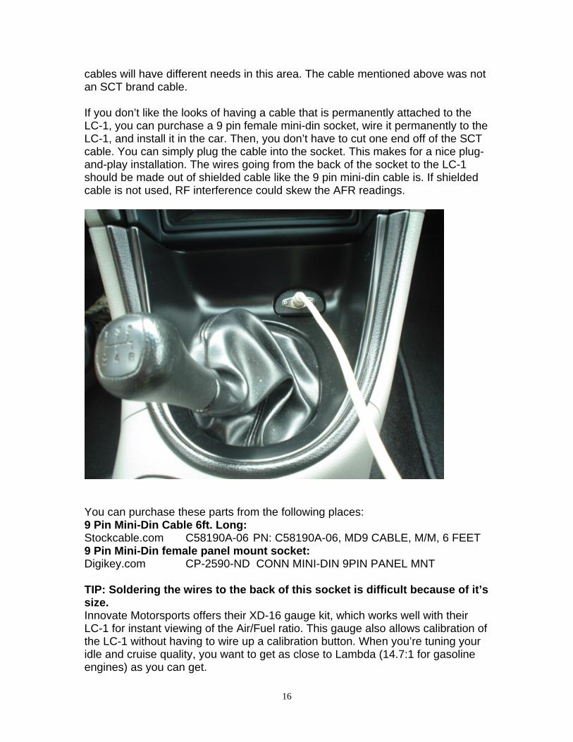
cables will have different needs in this area. The cable mentioned above was not an SCT brand cable. If you don’t like the looks of having a cable that is permanently attached to the LC-1, you can purchase a 9 pin female mini-din socket, wire it permanently to the LC-1, and install it in the car. Then, you don’t have to cut one end off of the SCT cable. You can simply plug the cable into the socket. This makes for a nice plug-and-play installation. The wires going from the back of the socket to the LC-1 should be made out of shielded cable like the 9 pin mini-din cable is. If shielded cable is not used, RF interference could skew the AFR readings.
You can purchase these parts from the following places: 9 Pin Mini-Din Cable 6ft. Long: Stockcable.com C58190A-06 PN: C58190A-06, MD9 CABLE, M/M, 6 FEET 9 Pin Mini-Din female panel mount socket: Digikey.com CP-2590-ND CONN MINI-DIN 9PIN PANEL MNT TIP: Soldering the wires to the back of this socket is difficult because of it’s size. Innovate Motorsports offers their XD-16 gauge kit, which works well with their LC-1 for instant viewing of the Air/Fuel ratio. This gauge also allows calibration of the LC-1 without having to wire up a calibration button. When you’re tuning your idle and cruise quality, you want to get as close to Lambda (14.7:1 for gasoline engines) as you can get.
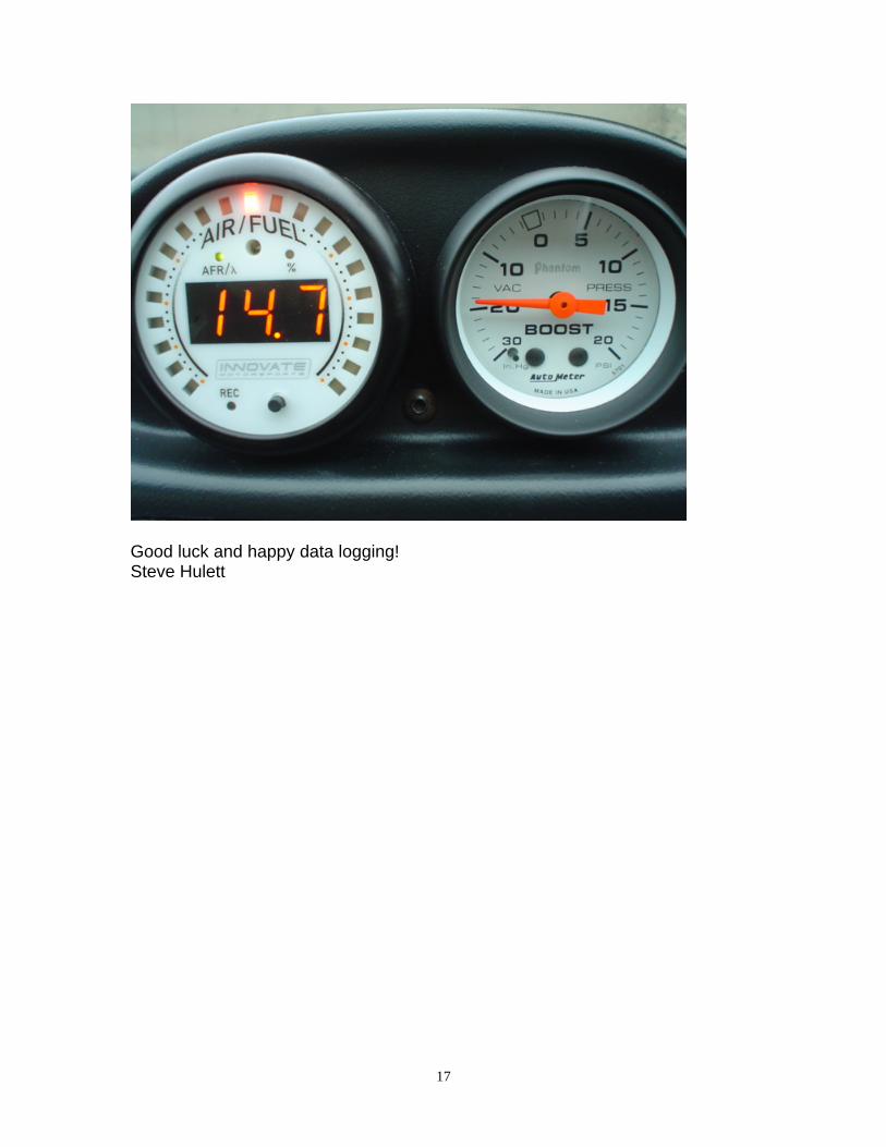
17
Good luck and happy data logging! Steve Hulett


![20111121 XCAL-LTE Operation Handbook [ZTE][Huawei] v1.0](https://img.pdfslide.us/doc/110x75/577cc5861a28aba7119cab17/20111121-xcal-lte-operation-handbook-ztehuawei-v10.jpg)
