Embed Size (px)
Citation preview

APPLICATION NOTE GaGe Measurement System: 24-channel Waveform
Generation and Acquisition for Spin-Echo Experiment
Nuclear Magnetic Resonance (NMR) makes use of the fact that the magnetic moments of atomic nuclei tend to precess about the flux lines of an applied magnetic field B. Atomic moments precess at the Larmor frequency ƒLARMOR, which is defined by the relation:
2ƒLarmor = γ B
The gyromagnetic ratio, γ, is the inverse ratio of the total angular momentum of an atomic nucleus to its resulting magnetic moment. The value of γ is generally distinct for each species of atomic nucleus so that measurement of γ may identify atomic species within unknown specimens. In addition, the value of B is the local magnetic field at the nuclear site, which differs from the applied magnetic field because of electronic screening by the local atomic environment. Consequently, scientists may use NMR to probe local atomic environments.
Generally, applied magnetic field values are chosen to result in Larmor frequencies that are within the Radio Frequency (RF) range. In the most basic NMR experiment, a specimen is subjected to a high magnetic field while being simultaneously irradiated by continuous RF radiation. The RF frequency is adjusted until absorption of RF energy by the specimen is maximized. This measured RF Larmor frequency allows calculation of γ , which then identifies atomic species within the specimen.
In medical Magnetic Resonance Imaging (MRI) systems, continuous RF frequencies are generally tuned to the Larmor frequency for a select atomic species - often hydrogen atoms within a water molecule. In addition to a large static magnetic field, smaller tri-axial gradient coils apply a smaller, slowly varying field. The coils are excited so that only a small volume element within the specimen has a Larmor frequency that is equal to the RF frequency. Measurement of the RF absorption as the gradient excitation varies allows the construction of a 3D image of the selected species within the specimen.
The application of modulated or pulsed, rather than continuous, RF radiation allows for a wealth of alternate NMR techniques. A technique called spin-echo NMR involves the application of RF pulses that cause multiple atomic moments to precess in phase. Over time, phase coherence of the atomic moments decays. The measured decay of phase coherence reveals information about overall atomic structure. Furthermore, later application of orientation-reversing pulses may cause the atomic moments to regain phase coherence. This rephrasing creates an RF spin-echo pulse that reveals further structural information.
A customer must construct a spin-echo experiment, which requires the excitation of 24 RF excitation coils and the acquisition of RF signals from 24 RF pick-up coils. The customer therefore requires a 24 simultaneous output waveform generator solution and a 24 simultaneous input digitizer solution. Since the Larmor frequency range is 0 – 20 MHz, the customer would like to use generation and sampling clock frequencies of 100 MHz. Spin-echo stimulus and response signals may have high dynamic ranges, so that 12 bits or more of vertical resolution on all generator and digitizer channels is required. The customer prefers a portable solution
A complete GaGe Measurement System was constructed for a challenging spin-
echo NMR experiment that requires 24 simultaneous high-speed analog input and output channels within a single portable chassis. In addition to using basic instrument functionality, the system exploits advanced timing capabilities that provide unmatched timing precision and measurement throughput.
Spin-Echo Experiment
Challenge

f
Solution
www.gage-applied.com/applications www.gage-applied.com/applications
and must control the system from the within the C and MATLAB Windows programming environments.
In addition to the basic generator and digitizer requirements, the customer requires extreme timing accuracy and stability. Firstly, all generator and digitizer channels must operate using a common master conversion clocking signal that has an absolute accuracy of better than 1 part-per-million. Secondly, the customer must position digitizer sampling clock edges with 1 nanosecond resolution within the spin-echo response signals, which typically occur 20 milliseconds after the excitation pulses.
Integrated Portable GaGe Measurement System
Through direct consultation with the customer, GaGe application engineers prepared a complete GaGe Measurement System to solve the requirement. Consisting entirely of standard GaGe catalog products and functionalities, the system is equipped with seven GaGe PCI instrument cards:
• Three Octopus CompuScope 8389 digitizers (8 channels, 14-bits, 125 MS/s max)
• Three CompuGen 8152 waveform generators (8 channels, 12-bits, 150 MS/s max)
• CompuGen 11G2 waveform generators (1 channel, 12-bits, 1 GS/s max)
All instrument cards are housed within a GaGe Instrument Mainframe 7500 portable lunchbox computer. A photograph of the system is shown on Page 1.
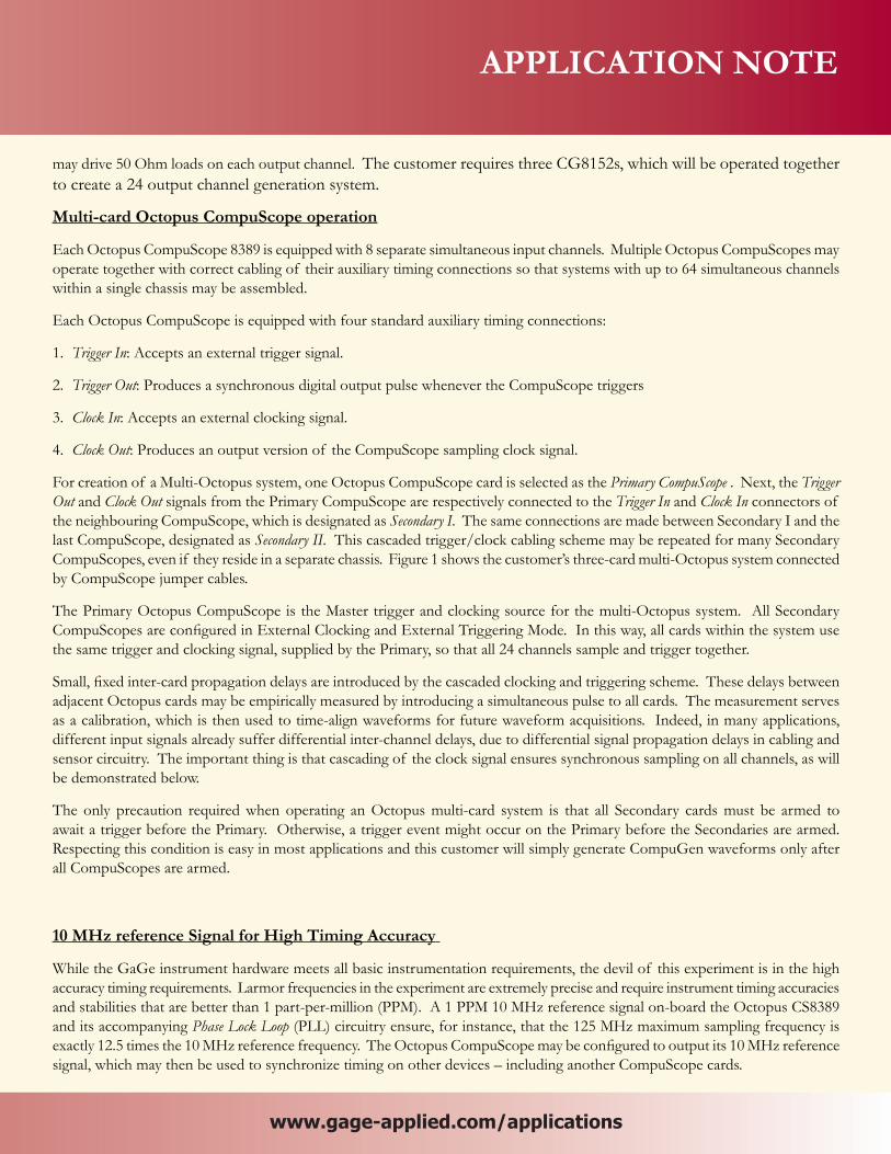
Figure 1 shows the electrical connectors for all GaGe PCI instrument cards, which are accessed through a PCI back-plate panel on the left hand side of the system. For convenience and slot economy, the auxiliary timing connections for the three CG8152 cards (Trigger In, Clock In and Marker Out) have been combined on a single auxiliary connector back-plate. In addition to the usual PCI back-plate retaining screw, all cards are secured within the chassis by back-end retention bracketing, which improves vibration resistance.
The main performance features of the GaGe PCI instrument cards meet the requirement of the customer’s application. Each Octopus CompuScope 8389 provides 8 simultaneous input channels at up to 125 MS/s sampling on all channels with 128 MegaSamples of on-board acquisition memory. The CS8389 acquires with 14 bits of vertical resolution and an impressive Signal-to-Noise Ratio (SNR) of 66 dB. The three CS8389s operate together as a 24 input multi-Octopus system, as discussed below.
The CompuGen 8152 provides 8 simultaneous output channels at up to a 150 MHz clocking speed on all channels with 2 MegaSamples of waveform memory behind each channel. The CG8152 provides 12 bits of vertical resolution and
Three CG8152Generators
CG11G2Generator
CG8152AuxiliaryConnections
Three CS8389Digitizers
P S I S II
Figure 1: Photo of connections to GaGe PCI instrument cards within the GaGe Measurement System. Multi-card jumper cables connected between adjacent Octopus CS8389 cards assign them the functional identities of Primary, Secondary I and Secondary II (from left to right).
f
APPLICATION NOTE
www.gage-applied.com/applications www.gage-applied.com/applications
may drive 50 Ohm loads on each output channel. The customer requires three CG8152s, which will be operated together to create a 24 output channel generation system.
Multi-card Octopus CompuScope operation
Each Octopus CompuScope 8389 is equipped with 8 separate simultaneous input channels. Multiple Octopus CompuScopes may operate together with correct cabling of their auxiliary timing connections so that systems with up to 64 simultaneous channels within a single chassis may be assembled.
Each Octopus CompuScope is equipped with four standard auxiliary timing connections:
1. Trigger In: Accepts an external trigger signal.
2. Trigger Out: Produces a synchronous digital output pulse whenever the CompuScope triggers
3. Clock In: Accepts an external clocking signal.
4. Clock Out: Produces an output version of the CompuScope sampling clock signal.
For creation of a Multi-Octopus system, one Octopus CompuScope card is selected as the Primary CompuScope . Next, the Trigger Out and Clock Out signals from the Primary CompuScope are respectively connected to the Trigger In and Clock In connectors of the neighbouring CompuScope, which is designated as Secondary I. The same connections are made between Secondary I and the last CompuScope, designated as Secondary II. This cascaded trigger/clock cabling scheme may be repeated for many Secondary CompuScopes, even if they reside in a separate chassis. Figure 1 shows the customer’s three-card multi-Octopus system connected by CompuScope jumper cables.
The Primary Octopus CompuScope is the Master trigger and clocking source for the multi-Octopus system. All Secondary CompuScopes are configured in External Clocking and External Triggering Mode. In this way, all cards within the system use the same trigger and clocking signal, supplied by the Primary, so that all 24 channels sample and trigger together.
Small, fixed inter-card propagation delays are introduced by the cascaded clocking and triggering scheme. These delays between adjacent Octopus cards may be empirically measured by introducing a simultaneous pulse to all cards. The measurement serves as a calibration, which is then used to time-align waveforms for future waveform acquisitions. Indeed, in many applications, different input signals already suffer differential inter-channel delays, due to differential signal propagation delays in cabling and sensor circuitry. The important thing is that cascading of the clock signal ensures synchronous sampling on all channels, as will be demonstrated below.
The only precaution required when operating an Octopus multi-card system is that all Secondary cards must be armed to await a trigger before the Primary. Otherwise, a trigger event might occur on the Primary before the Secondaries are armed. Respecting this condition is easy in most applications and this customer will simply generate CompuGen waveforms only after all CompuScopes are armed.
10 MHz reference Signal for High Timing Accuracy
While the GaGe instrument hardware meets all basic instrumentation requirements, the devil of this experiment is in the high accuracy timing requirements. Larmor frequencies in the experiment are extremely precise and require instrument timing accuracies and stabilities that are better than 1 part-per-million (PPM). A 1 PPM 10 MHz reference signal on-board the Octopus CS8389 and its accompanying Phase Lock Loop (PLL) circuitry ensure, for instance, that the 125 MHz maximum sampling frequency is exactly 12.5 times the 10 MHz reference frequency. The Octopus CompuScope may be configured to output its 10 MHz reference signal, which may then be used to synchronize timing on other devices – including another CompuScope cards.
The user may choose to provide an external high-accuracy 10 MHz reference signal to the CompuScope, so that global sampling accuracy is further improved. Some laboratory facilities are equipped with accurate 10 MHz reference signals that are used by all local experiments. Alternately, 10 MHz reference signals with accuracies a in excess of 50 parts-per-billion may be obtained from IRIG-B devices, which receive accurate timing signals from GPS satellites. The customer has selected the best available option and will use an atomic rubidium frequency standard whose 10 MHz reference frequency is accurate to better than 1 part- per-billion.
Set-up for Testing of Complete System
Testing of the GaGe Measurement System was accomplished using only GaGe stand-alone Windows application software: CGTest for all CompuGen hardware and GageScope Professional, the World’s Most Powerful Oscilloscope software, for all CompuScope hardware.
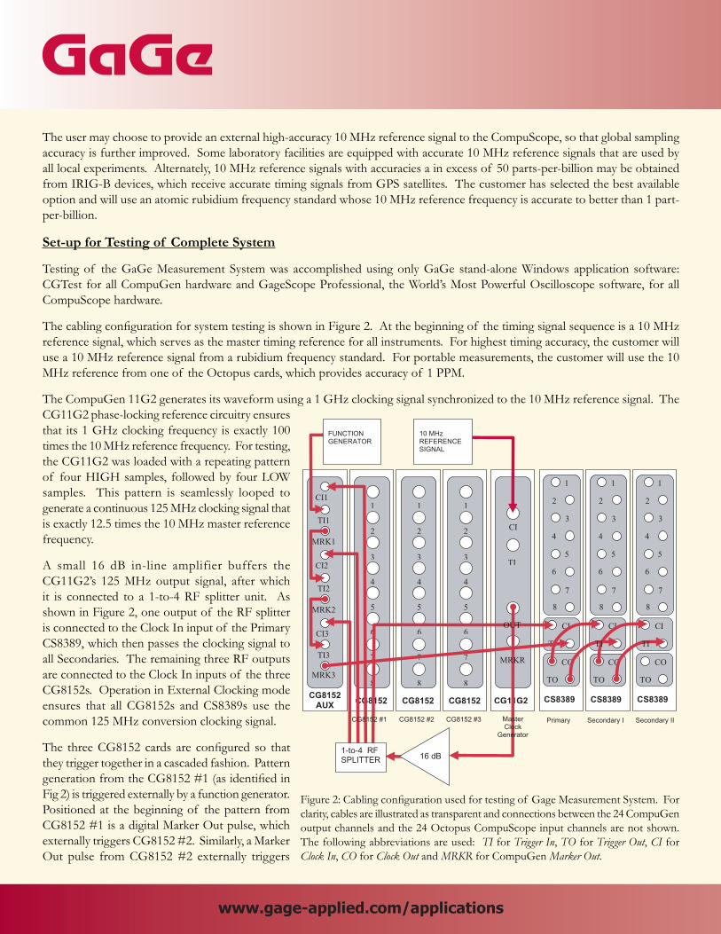
The cabling configuration for system testing is shown in Figure 2. At the beginning of the timing signal sequence is a 10 MHz reference signal, which serves as the master timing reference for all instruments. For highest timing accuracy, the customer will use a 10 MHz reference signal from a rubidium frequency standard. For portable measurements, the customer will use the 10 MHz reference from one of the Octopus cards, which provides accuracy of 1 PPM.
The CompuGen 11G2 generates its waveform using a 1 GHz clocking signal synchronized to the 10 MHz reference signal. The CG11G2 phase-locking reference circuitry ensures that its 1 GHz clocking frequency is exactly 100 times the 10 MHz reference frequency. For testing, the CG11G2 was loaded with a repeating pattern of four HIGH samples, followed by four LOW samples. This pattern is seamlessly looped to generate a continuous 125 MHz clocking signal that is exactly 12.5 times the 10 MHz master reference frequency.
A small 16 dB in-line amplifier buffers the CG11G2’s 125 MHz output signal, after which it is connected to a 1-to-4 RF splitter unit. As shown in Figure 2, one output of the RF splitter is connected to the Clock In input of the Primary CS8389, which then passes the clocking signal to all Secondaries. The remaining three RF outputs are connected to the Clock In inputs of the three CG8152s. Operation in External Clocking mode ensures that all CG8152s and CS8389s use the common 125 MHz conversion clocking signal.
The three CG8152 cards are configured so that they trigger together in a cascaded fashion. Pattern generation from the CG8152 #1 (as identified in Fig 2) is triggered externally by a function generator. Positioned at the beginning of the pattern from CG8152 #1 is a digital Marker Out pulse, which externally triggers CG8152 #2. Similarly, a Marker Out pulse from CG8152 #2 externally triggers
1
2
3
4
5
6
7
CI
TI
CO
TO
CS8389
8
CI
CG11G2
TI
1
CG8152
2
3
4
5
6
7
8
1
CG8152
2
3
4
5
6
7
8CG8152
AUX
CI1
TI1
MRK1
CI2
TI2
MRK2
CI3
TI3
MRK3
1
CG8152
2
3
4
5
6
7
8
1
2
3
4
5
6
7
CI
CO
TO
CS8389
8
1
2
3
4
5
6
7
CI
CO
TO
CS8389
8
1-to-4 RFSPLITTER
10 MHzREFERENCESIGNAL
Primary Secondary I Secondary IICG8152 #1 CG8152 #2 CG8152 #3 MasterClock
Generator
FUNCTIONGENERATOR
TI TI
MRKR
OUT
16 dB
Figure 2: Cabling configuration used for testing of Gage Measurement System. For clarity, cables are illustrated as transparent and connections between the 24 CompuGen output channels and the 24 Octopus CompuScope input channels are not shown. The following abbreviations are used: TI for Trigger In, TO for Trigger Out, CI for Clock In, CO for Clock Out and MRKR for CompuGen Marker Out.
www.gage-applied.com/applications www.gage-applied.com/applications

Results
Figure 3 shows a an image of the system during testing under GageScope, which operates all CompuScope hardware. Separate displays for the three CompuScope 8389 cards are shown in their functional order (from left to right, Primary, Secondary I and Secondary II).
As discussed, all CS8389s are externally clocked by the same 125 MHz clocking signal created by the CG11G2. Clocking and Triggering Signals are cascaded throughout the three-card multi-Octopus by the multi-Octopus jumper cables. For testing, a sine wave pulse was generated upon half of the twenty-four CG8152 channels. Figure 3 shows that all multi-Octopus input channels acquire the same sine pulse with the same amplitude and position. Consequently, Figure 3 provides basic validation that the multi-Octopus system operates correctly.
More powerful validation of the system is shown in Figure 4, where only cosmetic GageScope display settings have been changed
from Figure 3. The horizontal and vertical scales are magnified. In addition, GageScope Persistence mode ensures that display screens are not erased between successive waveform acquisitions. Persistence mode allows direct measurement of signal jitter, which is equal to the width in time of the ribbon-like waveform lines of Figure 4.
By definition, asynchronous waveform acquisition means that acquired waveforms and the digitizer sampling clock are not correlated in any way. Asynchronous acquisition always leads to a signal jitter of one sampling interval, which is 4 nanoseconds at the 125 MS/s sampling rate. This one-point jitter is no failing of the CompuScope hardware but is a fundamental consequence of signal and sampling clock asynchronicity.
When the sampling clock and acquired waveform are synchronous, waveform triggers always occurs at the same phase of the sampling clock. In this case, waveform stability becomes limited only by the intrinsic electrical jitter of the CompuScope hardware
Figure 3: Image of GageScope Professional operating the system during testing. The CompuGen 8152 waveforms acquired by each of the three 8-channel Octopus CS8389 cards are shown in three separate displays.
Figure 4: GageScope image taken under the conditions of Figure 3 with changes only to cosmetic display settings. Both the time-base and horizontal scale settings are magnified. Persistence or Overdraw Mode, which suppresses the erasure of successive waveforms, is also active.
www.gage-applied.com/applications www.gage-applied.com/applications
CG8152 #3. The user may compensate for slight inter-CompuGen delays by appropriately shifting each Marker pulse and/or pattern position in time. Finally, a Marker Out pulse from CG8152 #3 externally triggers the Primary CS8389, which then triggers all Secondary CompuScopes in the multi-Octopus system.

components. The magnified view of Figure 4 shows that waveform jitter on all channels of the multi-Octopus system is well below the 4 nanosecond sampling interval. Indeed, the residual jitter is below 1 nanosecond and more likely results from slight noise on the signals, rather than from intrinsic timing jitter. Consequently, Figure 4 clearly establishes the clock synchronicity of the entire system that results from the common 125 MHz clocking signal.
CompuScope Software Development Kits
Ultimately, the customer will create a tailored software application using GaGe’s powerful CompuScope C/C# and MATLAB Software Development Kits (SDKs). In addition to allowing full hardware control, SDKs also provide access to advanced CompuScope functionality that is not available under GageScope. For example, the customer’s short spin-echo response pulses typically occur 20 milliseconds after the CompuGen excitation pulses, which trigger the CompuScope hardware. Simple acquisition under GageScope, therefore, would waste CompuScope memory by acquiring over 2 million samples in order to extract only the few thousand trailing samples of interest.
From any CompuScope SDK, the user may activate the CompuScope Trigger Delay feature, which simply delays the CompuScope trigger by a programmable number of sample points. In the customer’s case, a Trigger Delay value of 2,000,000 points at 100 MS/s delays triggering until occurrence of the few thousand points of interest. Using the Trigger Delay feature from an SDK, therefore, the customer is able to expend only the minimum required amount of on-board memory.
Multiple Record Mode
The customer will use Multiple Record Mode to rapidly acquire sequential waveforms, which are stacked in on-board memory. For example, in Multiple Record Mode, 8000 waveforms of 2000 Samples each may be acquired into the CS8389’s 128 MegaSamples (16 MS/channel) memory.
Between sequential acquisitions in Multiple Record mode, trigger circuitry is re-armed in hardware with no software intervention required. Software intervention is accompanied by software latencies of indeterminate length, which may lead to trigger loss in an unpredictable fashion. By contrast, hardware re-arming in Multiple Record Mode is completely deterministic and requires no more than 2 microseconds at the smallest waveform lengths. For waveform lengths longer than 16,000 Samples, the hardware re-arm time drops below 0.5 microseconds.
Stored with each Multiple Record waveform trigger is a Trigger Time-Stamp value that is derived from a 44-bit on-board counter output, which is latched upon each trigger event. The counter may be clocked by the CompuScope sampling clock or by a fixed 133 MHz on-board oscillator. Trigger Time Stamps, therefore, allow measurement of each trigger event’s occurrence time with an accuracy of better than 10 nanoseconds.
CompuGen Link’N’Loop Functionality
The customer’s NMR Larmor frequencies are accurate to better than 1 part-per million and CompuScope sampling clock edges must be positioned with a precision of 1 nanosecond – even after a 20 millisecond spin-echo delay. In the simplest approach, clock edge positions might be adjusted within 1 nanosecond by appropriately modifying the 100 MHz clocking signal loaded as CG11G2 pattern. The 16 MegaSamples of CG11G2 memory at a clocking speed of 1 GHz, however, only allows for a maximum arbitrary pattern duration of 16 milliseconds, which is below the 20 millisecond requirement.
Fortunately, because the customer’s clocking signal is mostly repetitive, the requirement may exploit CompuGen Link’N’Loop mode. Somewhat similar to CompuScope Multiple Record Mode, Link’N’Loop mode allows a portfolio of waveform patterns to be pre-loaded to CompuGen memory. After loading, the user may rapidly switch amongst the waveform portfolio with a deterministic 64 point pattern switching time. Each waveform may be seamlessly looped for an adjustable loop count.
The customer’s requirement is satisfied through the creation of three Link’N’Loop waveform segments that are illustrated in Figure 5. The first Link’N’Loop segment contains all 0 values but also generates a Marker Out Pulse that triggers CG8152 #1,

which, in turn, ultimately triggers all other instrument cards.
The second Link’N’Loop segment is a “coarse” repetitive 100 MHz clocking signal. For example, let us assume that Segment #2 is exactly 6,400 samples long and contains exactly 640 clock pulses of 10 samples each. If it operates at a 1 GHz clocking rate and seamlessly loops Segment #2 exactly 3125 times, the CG11G2 will create a continuous 100 MHz clocking signal for a duration of exactly 6,400 x 3125 / 1 GHz = 20 milliseconds. The user may lengthen or shorten the duration of Segment #2 in 6.4 microsecond increments, simply by increasing or decreasing the 3125 loop count.
Once Segment #2 has completed, Segment #3 serves as a single-shot “Footer” clocking pattern, whose clocking edges may be placed precisely with 1 nanosecond resolution simply by shifting the entire pattern left or right. The length of Segment #3 is only a few thousand 100 MHz clock cycles, as required to complete the CompuScope spin-echo response signal acquisition. There are two constant 64-sample segment switching delays within the CG11G2 Link’N’Loop generation sequence, in addition to other constant propagation delays. The user must compensate for these delays for correct clocking edge positioning. This is most easily done once by trial-and–error.
The overall 3-segment Link’N’Loop pattern may be endlessly looped by the CG11G2 or generated once upon its receipt of an external trigger pulse. By using CompuGen Link’N’Loop mode, therefore, the customer is able to reduce the raw CG11G2 memory length requirement from an unavailable 20 MegaSamples to only a few tens of thousands of samples.
Seamless Looping of Segment #2
Coarse LongSegment #2
Footer Segment #3MarkerSegment#1
Endless Looping of Overall Link’N’Loop sequence
Switch Switch
Figure 5: The diagram shows the three waveform segments in CompuGen Link’N’Loop mode that are required to create the user’s precision 100 MHz clocking signal.
Conclusion
A complete portable 24 channel high-speed analog input/output GaGe Measurement System was constructed for a demanding spin-echo NMR using only CompuGen and CompuScope PCI instrument cards from the GaGe catalog. A high-speed CompuGen CG11G2 generator card was used to create a high accuracy, synchronous Master clocking signal for by all GaGe instruments.
Almost all functionality required for the application is available under GaGe’s powerful stand-alone application software: CGTest and GageScope. These functionalities include:
• Loading of independent arbitrary waveforms onto all four CompuGen cards.
• Simultaneous operation of all three CompuScope cards
• Creation of a 125 MHz Master clocking signal with the CompuGen 11G2
• Operation of a multi-Octopus system with jumper cables supplied

Copyright © 2005 Gage Applied Technologies. All rights reserved.
Drivers for both Windows 95 and Windows NT are available for the CS8500. In addition, GageScope software will allow the customer to do exactly what they asked: verify the operation of the CompuScope 8500/PCI without writing any code.
This application brief is provided “as is” without any warranties of any kind, either expressed or implied, including but not limited to the implied warranties of
Results
GaGe does not warrant the accuracy and completeness of the material contained herein. GaGe may make changes to this material, or to the products described in it, at any time without notice.
900 N. State Street • Lockport, IL 60441 • 1-800-567-GaGe • Phone: +1-514-633-7447 • Fax: +1-514-633-0770 • [email protected]
Gage’s Octopus™ family of multi-channel digitizers features up to 8 channels, up to 4 GB of on-board acquisition memory, and up to 125 MS/s sampling per channel on a single-slot PCI card.
Features
• 2, 4, or 8 digitizing channels
• 12 bit or 14 bit vertical resolution
• 128 MS to 2 GS on-board acquisition memory
• 10, 25, 50, 65, 100, or 125 MS/s maximum sampling per channel
• More than 100 MHz input analog bandwidth
• Full-featured front-end, with software control over input ranges, coupling and terminating impedance
• 32 bits, 66 MHz PCI standard for 200 MB/s data transfer to PC memory
• Ease of integration with External or Reference Clock In and Clock Out, External Trigger In and Trigger Out
• eXpert™ on-board processing FPGA firmware available for Signal Averaging, FIR filtering and Peak Detection
• Programming-free operation with GageScope® oscilloscope software
• Software Development Kits available for LabVIEW, MATLAB, C/C#
• Operation with cabling configuration for common clocking and triggering of all instrument cards
• Usage of a Master 10 MHz reference signal to provide high accuracy timing on all instruments
More advanced functionalities that are accessible from GaGe Software Development Kits include:
• Usage of the CompuScope Trigger Delay feature to minimize CompuScope memory usage in Multiple Record Mode
• Usage of CompuGen Link’N’Loop Mode to allow nanosecond positioning of CG11G2 clocking edges long after the start of generation.
Knowing the powerful GaGe PCI instrument portfolio and understanding their basic and advanced functionality, GaGe application engineers were able to recommend a GaGe Measurement System that completely fulfills this challenging requirement.
Octopus CompuScope Family
www.gage-applied.com/applications


![Rephrasing for Pau Exam[1]](https://img.pdfslide.us/doc/110x75/55cf94e2550346f57ba51634/rephrasing-for-pau-exam1.jpg)