Embed Size (px)
Citation preview

THIS INFORMATION PROVIDED BY AUTOMATIONDIRECT.COM TECHNICALSUPPORT IS SUPPLIED "AS IS", WITHOUT ANY GUARANTEE OF ANY KIND.These documents are provided by our technical support department to assistothers. We do not guarantee that the data is suitable for your particularapplication, nor we assume any responsibility for them in your application.
PRODUCT FAMILY: Sure Servo Number: AN-SERV-002
Subject: Torque control with a servo motor Date issued: May 3-2006Revision: First edition,rev A
This example shows how we can control tension of a web using the torque controlfeatures of the servo system with the help of a PLC DL06.The winder is a typical example of constant tension center winder control.
The diagram above represents a rewinder that makes the winding of plastics sheetsat a constant web speed; In this case the right coil is the rewinder D, that will bewound at a constant speed of 328 feet/min,with a constant tension given by thetorque supplied by the servomotor. The unwinder (A) is controlled by other system, not shown here, to maintain theweb speed constant to feed the rewinder, helped with the rollers B and C.This simple example considers the assumptions and the steps necessary to definethe drive system for a rewinder, that is, given the mechanical properties of theprocess, we will determine the size of the servo and the gear reducer, the signals tobe exchanged between the process, the PLC and the servo drive through wiringdiagram and explanations, the program on the PLC, the parameter configuration ofthe servo drive, and the expected operation. Tuning is not considered in thisexample.The motion drive system consists of a servomotor, whose size will be determined,and a reducer to move the shaft of the rewinder. Notice that the torque caused bythe necessary tension, which is constant, varies with the radius of the coil.
Load cell
TensionTangential speed
Servomotor
Encoder
Application Note AN-SERV-002

Application Note AN-SERV-002
2
The torque to be supplied has to be calculated by a PLC DL06, that receives a linearspeed signal from the encoder located on the roller, which has also a load cell toindicate the tension continuously. Notice that the web tension on the horizontaldirection A-B is the same of the polyethylene on the direction from the roll C to therewinder D.
The resistive torque should be the tension expresssed in Newtons multiplied by theradius in meters, to get the resistive torque in Newton-meter.
The control system will consist of the servo, a PLC DL06 and a touch screen panelto input the desired PLI (pounds per linear inch, is in the range 0.5 to 1 PLI, thewidth of the spool (30 to 60 inches), the web speed is in the range 50 to 100 m/min;the control of the unwinder can be implemented on the PLC, but it is not described.
Determination of speed and torque of the rewinderFirst, it is necessary to determine the speed and torque in the operation of therewinder.
Let us consider that we have a rewinder for plastic sheets (polyethylene), with thefollowing dimensions & features:
Roll
Core diameter 6 ¼ inches 159 mm
External diameter 30 inches 762 mm Max radius 0.381 m
Width of the winder 60 inches 1.52 m
Weight of the roll 1800 lb 818 Kg
Tension applied 1 PLI or 60 lb => 267.5 Newton
Feed speed 328 feet/minute 100 m/min =>1.67 m/s (A)
The winder begins to rotate in such a way that the feed speed increases from 0 tothe feed speed in 50 seconds
Servo drive
PLC DL06
Rewinder

3
The rotational speed of the winder is determined with the formula
w = v/r (B)
being w the speed in radians/second, v the speed of the plastic sheet in [m/s] and ris the radius of the roll in meters
We have the following rpm of the rewinder
- When the roll is in the beginning the core determines the radius, which is veryclose to the diameter of the core.
w = 1.6667/0.1588*2 = approximately 20.997 rad/s or 200.51 rpm (C)
- When the roll is completed with 30 inches
w =1.6667/0.762*2 = 4.3745 rad/s or 41.77 rpm (D)
This data allows us to determine the gear reducer to be used to drive the winder
Let us consider that a servomotor can deliver 3000 rpm.
Since the maximum rotational speed of the roll is 200.51 rpm according to (C), thetheoretical ratio is 14.96 (3000/200.51). Looking at Shimpo Drives, their ABLEseries gear reducers will work.
Let us select a ratio 15:1, frame size C, NEFAV, right angle (E)
What is then necessary to determine the torque?We have to determine the running torque and the dynamic torque; for the dynamictorque we need to calculate the involved inertias:
The core inertia, easily determined as below
Inertia of the plastic core 0.513[Kg-m2] from below
Inertia of the shaft holding the bobbin 2 [Kg-m2] estimated
Inertia of the reducer 0.415[Kg-cm2] or 4.15E-05[Kg-m2]
The inertia of the motor 0 for now
Total fixed inertia 2.513 [Kg-m2] (F)
Calculus of variable inertia of the core, using the cylinder formula: The inertia of a solid cylinder is
J= r*(L*r4*p)/2 (G)
being r the density of the material
Width of the plastic core is 1.6 meter
External diameter of the core 0.158 meter
Internal diameter of the core 0.132 meter
Thickness of the walls 0 meter
Material of the reel core Plastic
Density of material 2700 [Kg/m3]
The thickness of the plastic web is 0.15 mm
Then the solid core inertia is 0.538 [Kg-m2]
Let us remove the orifice 0.025 [Kg-m2]
Application Note AN-SERV-002
Application Note AN-SERV-002
4
Then total inertia of the plastic core is 0.513 [Kg-m2] (H)
The resistance due to the friction of the different parts.For that, we will consider:
Reducer efficiency 95%
System efficiency 87%
Let us consider the inertias involved
Let us estimate the shaft inertia as 2 [Kg-m2]
Density of the plastic is determined as the weight divided by the volume
The volume is V= (ro2- ri
2)*L*p
This is 0.665 [m3]
The density of the web material is 1231 [Kg/m3]
Then we are ready to calculate the inertia, torque, rpm, etc. in function of the time.
In order to know how the radius will increase with the web, we can establish thatthe radius R(t) is the core radius plus the number of layers times the thickness of theweb material. The number of layers is the distance of the web divided by thecircumference or :
R(t) = core/2 + 2*thickness*distance(t)/(2*p*R(t))
rearranging the equation by multiplying by 2*p*R(t) and moving all to one side
2*p*R(t)2 - p*core*R(t) - 2*thickness*distance(t))=0 we have the well known seconddegree equation. Since x= (-b +/-sqrt(b2-4ac)/2a, then the solution to R(t) is:
R(t) = (+p*core +sqrt(p2*core2 + 16*p*thickness*distance(t)) /(4*p)
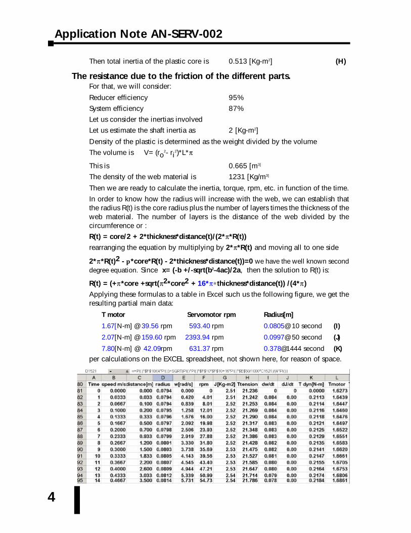
Applying these formulas to a table in Excel such us the following figure, we get theresulting partial main data:
T motor Servomotor rpm Radius[m]
1.67[N-m] @ 39.56 rpm 593.40 rpm 0.0805@ 10 second (I)
2.07[N-m] @ 159.60 rpm 2393.94 rpm 0.0997@ 50 second (J)
7.80[N-m] @ 42.09rpm 631.37 rpm 0.378@1444 second (K)
per calculations on the EXCEL spreadsheet, not shown here, for reason of space.
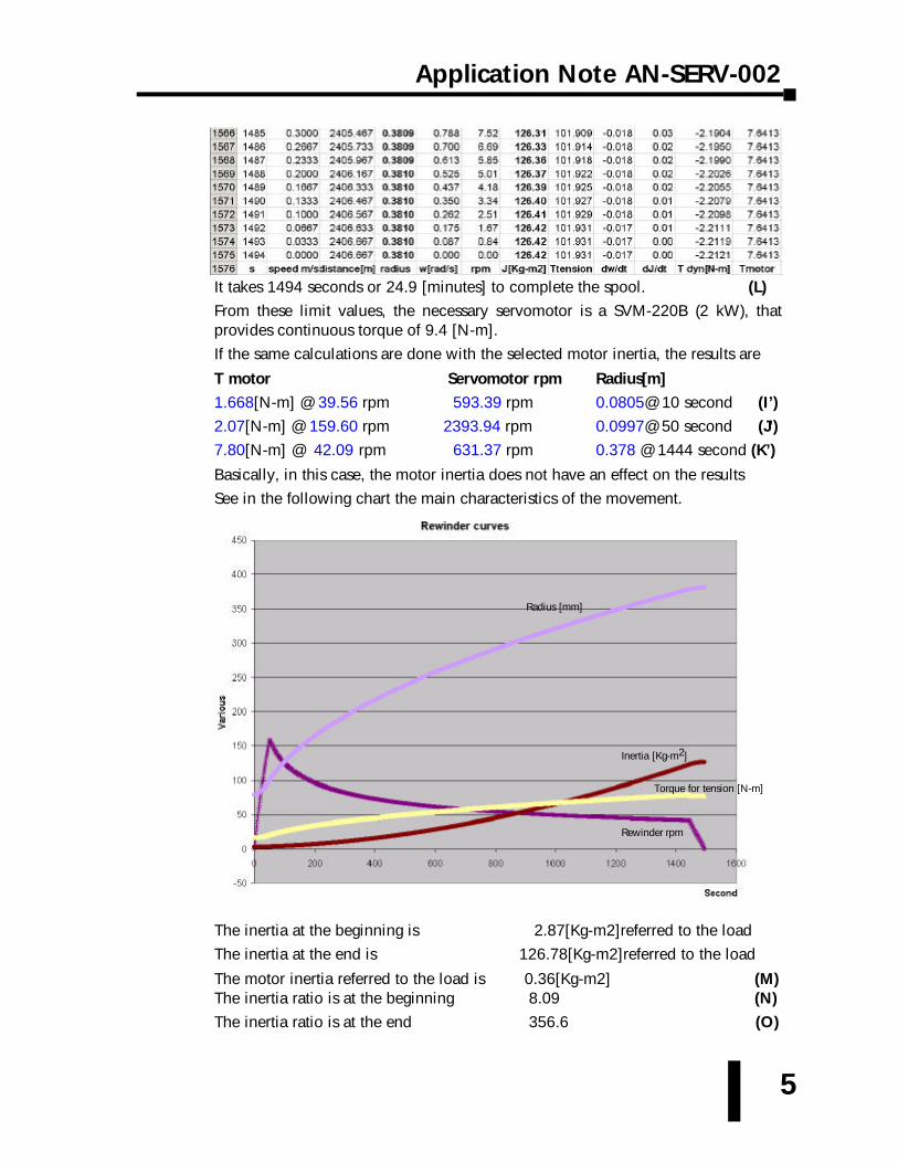
It takes 1494 seconds or 24.9 [minutes] to complete the spool. (L)
From these limit values, the necessary servomotor is a SVM-220B (2 kW), thatprovides continuous torque of 9.4 [N-m].
If the same calculations are done with the selected motor inertia, the results are
T motor Servomotor rpm Radius[m]
1.668[N-m] @ 39.56 rpm 593.39 rpm 0.0805@ 10 second (I’)
2.07[N-m] @ 159.60 rpm 2393.94 rpm 0.0997@ 50 second (J’)
7.80[N-m] @ 42.09 rpm 631.37 rpm 0.378 @ 1444 second (K’)
Basically, in this case, the motor inertia does not have an effect on the results
See in the following chart the main characteristics of the movement.
The inertia at the beginning is 2.87[Kg-m2]referred to the load
The inertia at the end is 126.78[Kg-m2]referred to the load
The motor inertia referred to the load is 0.36[Kg-m2] (M)The inertia ratio is at the beginning 8.09 (N)
The inertia ratio is at the end 356.6 (O)
5
Application Note AN-SERV-002
Radius [mm]
Inertia [Kg-m2]
Rewinder rpm
Torque for tension [N-m]

Application Note AN-SERV-002
6
PLC considerations:Let us see now what is necessary on the PLC side:
Tension on the webThe tension on the web is measured with the load cell and delivered to the PLC withan analog signal 0-10 Volt, being the 10 Volt the span of the load cell device;typically 30% above the operating point. Since the required maximum tension is267.5 [Newton], then the span will be 350 Newton in this example.
Let us see what is the PLC raw value for a measurement of 267.5 Newton (O)
267.5/350*10 is 7.6428 Volt or in PLC raw value, 267.5/350*4095 = 3129. Thisshould be the normal force of the tension measured on the load cell.
Measurement of the web speed The PLC will receive the pulses of an encoder TRD-GK1200-RZD (1200 pulses perrevolution). This encoder was selected to produce a pulse frequency close to thelimit that the PLC can read. (More precision can be obtained if the module H0-CTRIO is used, since it can read up to 100 kHz, together with an encoder that hasa larger number of pulses per revolution, for example 5000 ppr, and/or a smallerdiameter roller C). We will calculate the speed every 50 [ms], to make the PIDsample work at the same period. We will count the number of pulses every 50 [ms].This will allow to determine the tangential speed of the web.
Let us say the the roller C has a diameter of 100 mm. Then the typical rotationalspeed will be 1.667[m/s]/(px0.100 m) [cycles/s] by the formula (B). This results inapproximately 5.30 cps, or 1200*5.30 = 6366 pulses per second, since eachrevolution of the encoder produces 1200 pulses, or 318 pulses every 50 [ms] (P)
Determination of the spool speedThe spool speed, which is proportional to the servomotor speed, can be read fromthe analog output of the servo (or the digital value in the memory if using MODBUS,address 0002h, if the parameter P0-02 is configured as 06, actual motor velocity).
Let us check what is the calculated speed on the PLC at a servo motor rotation of2393 rpm, (assuming that the servo is calibrated to deliver 8 [Volt] at 3000 rpm), theservo can generate then 2393/3000*8 [V]= 6.381 Volts. This is interpreted as6.381/10*4095 = 2613 counts on the scale 0-4095 (note that there are some errorof truncation).
Determination of the radiusThe external radius of the web spool can be calculated with the following relation:
The tangential speed is v = w/r(t), from formula (B); since the magnitude v can becalculated with the counts of the encoder pulses, and the servomotor speed iscalculated by the servo, the radius r(t) at any time is w/v times a constant.
We know that the radius at this time is 99.7 mm (from (J). Therefore, the quotient318/2613 with a constant should be equivalent to 99.7 [mm].
The constant is then: 99.7= K1x318/2613 => K1= 99.7*2613/318= 819.233
7
Having this constant, at a servo motor rotation of 631.37 rpm, the servo cangenerate 631.37/3000*8= 1.683 Volts. This is interpreted as 1.683/10*4095= 689.4counts on the scale 0-4095. The number of counts on the encoder counts will be318 if the speed is 100 m/min. then the radius will be K1*318/689.4 => 377.78mm. In fact, per the more exact calculation on EXCEL, the radius will be 378.1 mm.This is an error of (378.1- 377.78)/378.1=> 0.084%, which is acceptable for thispurpose.
There are other errors of truncation, but the error does not seem to be above 0.5%
The calculation of the radius is important, to work with the torque. Recall that theload cell measures only tension.
The web tension has to be maintained constant by the application of a torque by theservo motor . This torque can be controlled with a PID function already built in thePLC DL06. The operator will enter the desired PLI and the PLC will calculate thenecessary torque using the calculated radius.
The PID table initial register in this example is V10000.
Torque setpoint of the PID loop.The PLC has to generate the torque setpoint signal and the command to start theoperation.
The set point for the torque then will be given by the desired tension multiplied bythe radius (function of time). In this case, let us recall that the PLC tension is 267.5Newton, and the measurement of this value results in a PLC raw value 3129, per(O). This is the maximum tension that the machine will deliver. Of course, theoperator can adjust the PLI value to a lower value. This value is multiplied by theradius on the PLC to generate the setpoint to the servo.
This value in entered in the algorithm of the PID on the address V10002 as adecimal number format.
Torque on the process variable of the PID loop.The PLC has to generate the corresponding torque signal for the process variablethat is indirectly obtained when measuring the tension with the load cell .
The process variable torque then will be given by the measured tension multipliedby the radius (function of time).
This value in entered in the algorithm of the PID on the address V10003 as adecimal number format.
Control output of the PID loop (torque to be delivered by the servo).The PLC has to generate the corresponding signal for servo to apply the propertorque to maintain the tension constant.
The PID algorithm will generate an output in the range 0-4095 in decimal formatthat will be sent with an analog signal of 0 - 10 Volt on the terminal T-ref.
In order to scale this properly, we consider:
The maximum torque that the servomotor will supply can be 9.4 [N-m]; this will beour 100%.
Application Note AN-SERV-002
Application Note AN-SERV-002
8
We know by the calculations on the previous pages that the servomotor has tosupply 7.8 [N-m] when the radius is 378 mm.
7.8 [N-m] is 82.98% of the full torque of the motor; then the output on thiscondition is in PLC raw value a figure of 3397. This will allow us the scale the outputproperly. Of course the Servo can and must deliver more torque if the systemrequires it... On the initial operation, however, the servo requires a lot less torquethan this figure, and for example at 50 seconds of operation, the required torque isonly 2.07 [N-m]. This concept is used on the ladder diagram, where there are moreexplanations.
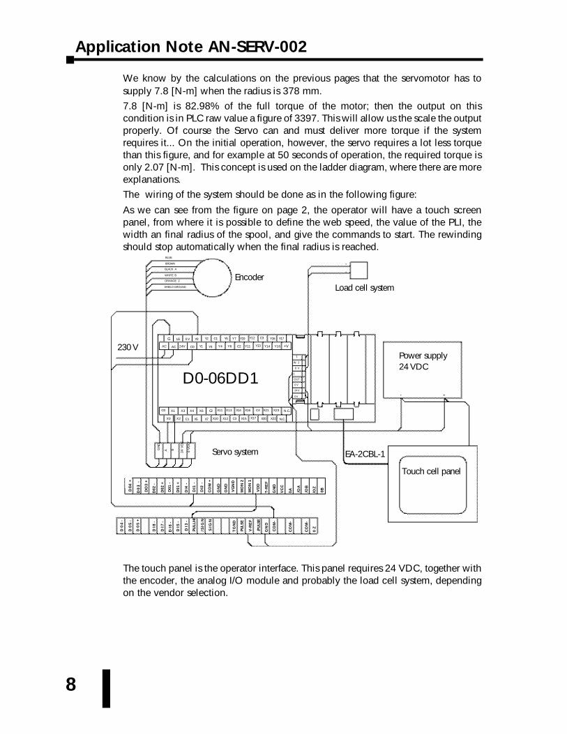
The wiring of the system should be done as in the following figure:
As we can see from the figure on page 2, the operator will have a touch screenpanel, from where it is possible to define the web speed, the value of the PLI, thewidth an final radius of the spool, and give the commands to start. The rewindingshould stop automatically when the final radius is reached.
The touch panel is the operator interface. This panel requires 24 VDC, together withthe encoder, the analog I/O module and probably the load cell system, dependingon the vendor selection.
Load cell systemEncoder
D0-06DD1
Servo system
Touch cell panel
Power supply 24 VDC
+V
G LG Y00V Y7Y5C1Y2
AC C2Y6Y4Y3Y1C0AC 24V Y13Y11
Y17Y16
Y16Y14
C3Y12Y10
X23X21C4X16 N.C.
EA-2CBL-1
C2X6X4X3X1C0
X7C1 X5X2X0
X13
X22X20X15C3X12X10 X17
X11 X14
GN
D
A B
24V
DC
0V
OLT
1
OUT 2
24 V
1
0 V
IN 2
0 V
D0
4-
SIG
N
/SIG
N
PULL
HI
DI5
-
D0
5-
DI7
-
DI8
-
DI6
-
D0
5+
V-R
EF
TG
ND
PULS
E
/PU
LSE
GN
D
CO
M-
CO
M-
CO
M-
0Z
D0
3-
D01
-
D04
+
D02
+
D02
-
DO
3+
D01
+
DI4
-
T-R
EF
VD
D
MO
N1
MO
N2
VG
ND
GN
D
GN
D
CO
M+
DI2
-
DI1
-
0B/OZ
/OB
/OA
0AVC
C
GN
D
DI3
-
230 V
BLUE
BROWN
BLACK A
WHITE B
ORANGE Z
SHIELD GROUND
N.C.
0 V

9
Application Note AN-SERV-002
For this example we have selected a panel EA7-T6C, and the PLC is a D0-06DD1.
Let us work on the project of the touch screen:
We will create, for now, 2 screens; one if for the visualization of the process andthe other are the initial settings. See the screens on the figure below:
Screen 1
Screen 2

Application Note AN-SERV-002
10
As a convenience for the programming, we have selected to use floating pointsnumbers for the numeric displays and entries
These are the tags created:
This deserves some explanations:
RADIUS on V5000 is the desired radius input by operator on the settings screen
WIDTH on V5002 is the desired width of the web, set on the settings screen
PLI on V5004 is the desired tension input by operator, in pounds per inch.
WEB SPEED on V5010 is the desired speed,set on the settings screen
The other tags are the measured or calculated value, to be displayed on the screen
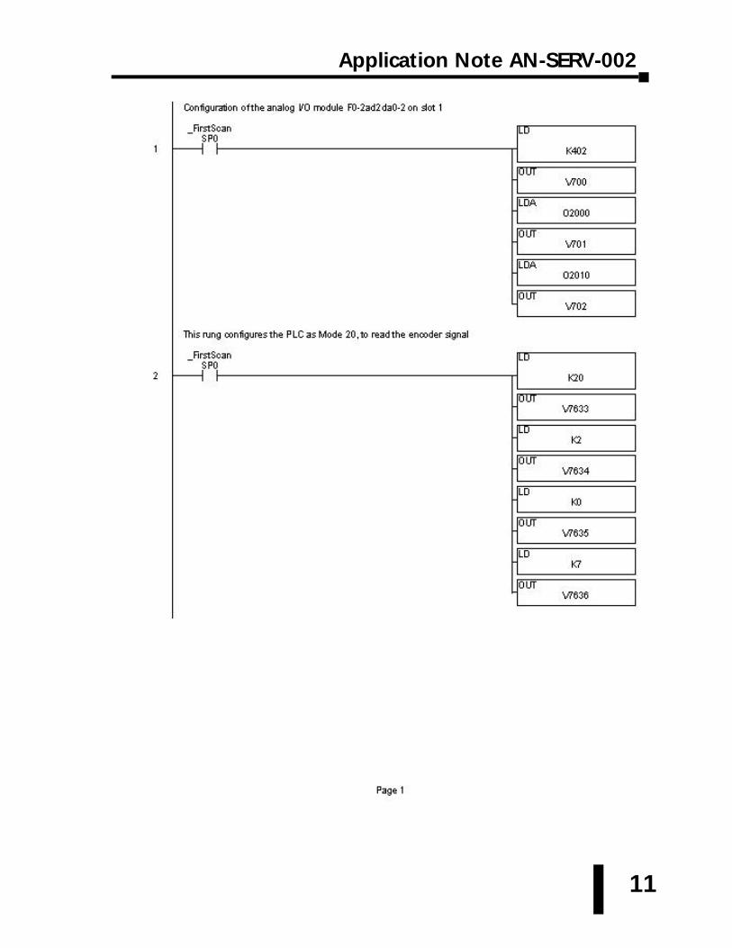
The PLC D0-06DD1 will have an analog module F0-02AD2DA-2 on slot 1.
The PLC will read the input data, process the information, execute the PID loop, andthen write the outputs to the corresponding registers.
The next step is to create the PLC program.
The PID loop is created with the PID table beginning on address V10000.
More explanations are given in the comments of the ladder diagram.
11
Application Note AN-SERV-002

Application Note AN-SERV-002
12
This is the high speed counter to count the pulses from the encoder
The bit 8 of the memory V10001 toggles on each PID algortthm sampling
This timer delays the pulse C0 for 20 ms to avoid calculation while the PID is executing
This rung sets the clock to execute the ladder calculations
The idea here is to allow the PID execution at certain timeon the PLC, different from the ladder execution, to avoidoverlap in calculations. In this case the PLC will executealways every 50 ms, which is enough time to process thisrelatively slow proces.
13
Application Note AN-SERV-002
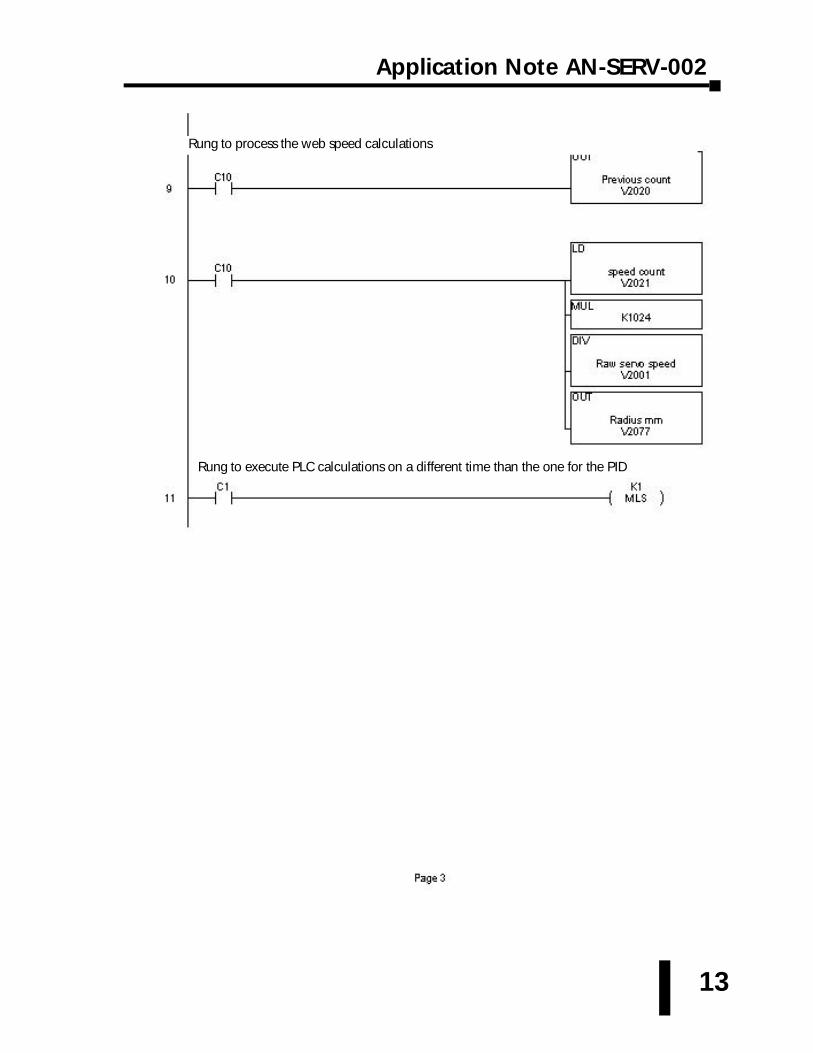
Rung to process the web speed calculations
Rung to execute PLC calculations on a different time than the one for the PID
Application Note AN-SERV-002
14
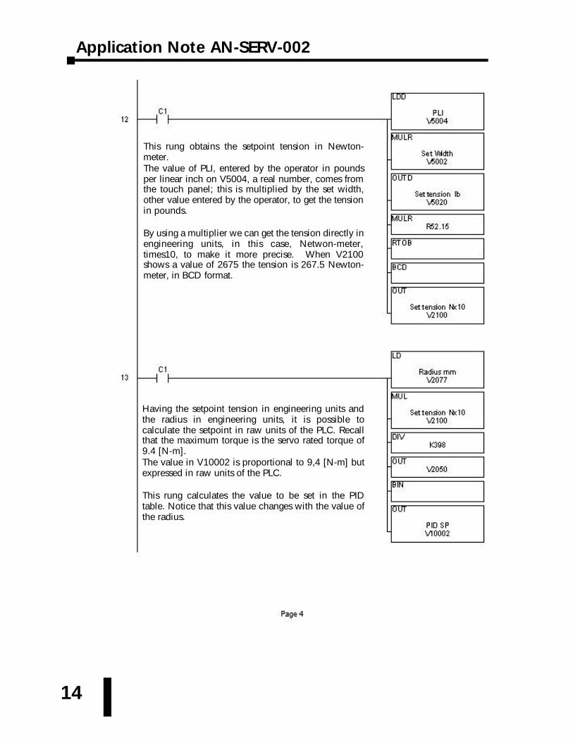
This rung obtains the setpoint tension in Newton-meter. The value of PLI, entered by the operator in poundsper linear inch on V5004, a real number, comes fromthe touch panel; this is multiplied by the set width,other value entered by the operator, to get the tensionin pounds.
By using a multiplier we can get the tension directly inengineering units, in this case, Netwon-meter,times10, to make it more precise. When V2100shows a value of 2675 the tension is 267.5 Newton-meter, in BCD format.
Having the setpoint tension in engineering units andthe radius in engineering units, it is possible tocalculate the setpoint in raw units of the PLC. Recallthat the maximum torque is the servo rated torque of9.4 [N-m].The value in V10002 is proportional to 9,4 [N-m] butexpressed in raw units of the PLC.
This rung calculates the value to be set in the PIDtable. Notice that this value changes with the value ofthe radius.

15
Application Note AN-SERV-002
Having the load cell tension in engineering units andthe radius in engineering units, it is possible tocalculate the real process variable torque in raw unitsof the PLC. Recall that the maximum torque is theservo rated torque of 9.4 [N-m].The value in V10003 is proportional to 9,4 [N-m] butexpressed in raw units of the PLC.
This rung calculates the value to be set in the PIDtable. Notice that this value changes with the value ofthe radius.
The output of the PID, which is the desired torque to besupplied by the servomotor, has to be delivered to the servodrive in a signal 0-10 Volt. The signal can deliever up to 4095 counts.
This rung starts and stops the system.
Application Note AN-SERV-002
16
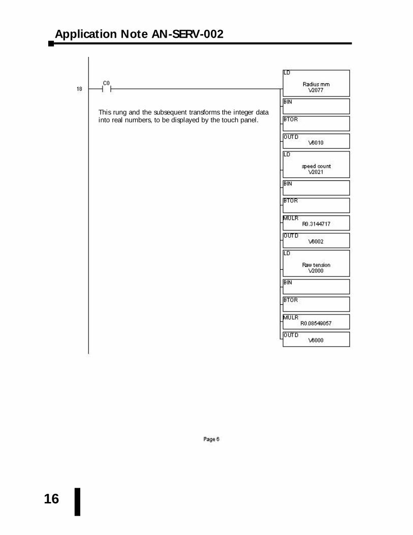
This rung and the subsequent transforms the integer datainto real numbers, to be displayed by the touch panel.
17
Application Note AN-SERV-002
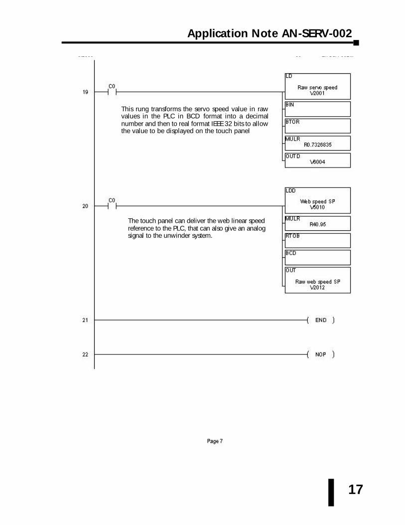
The touch panel can deliver the web linear speedreference to the PLC, that can also give an analogsignal to the unwinder system.
This rung transforms the servo speed value in rawvalues in the PLC in BCD format into a decimalnumber and then to real format IEEE 32 bits to allowthe value to be displayed on the touch panel
Application Note AN-SERV-002
18
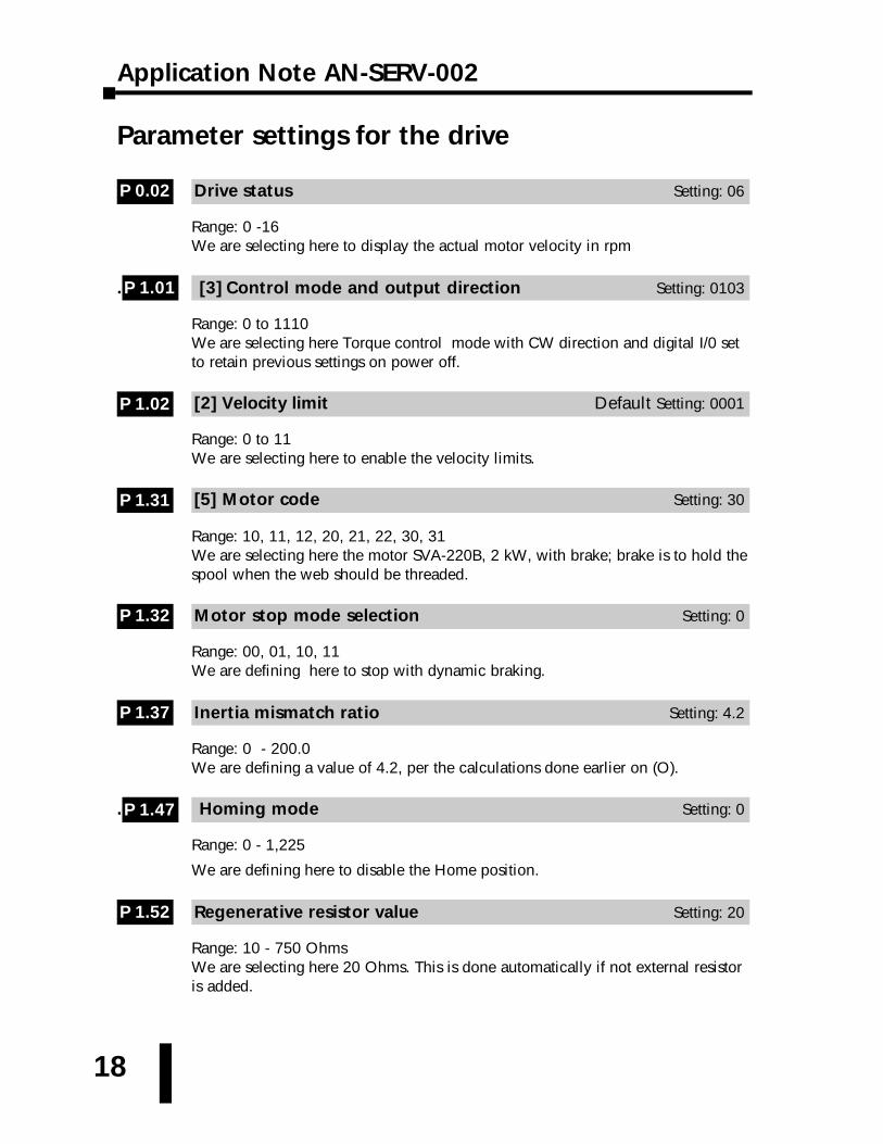
Parameter settings for the drive
Drive status Setting: 06
Range: 0 -16We are selecting here to display the actual motor velocity in rpm
. [3] Control mode and output direction Setting: 0103
Range: 0 to 1110We are selecting here Torque control mode with CW direction and digital I/0 setto retain previous settings on power off.
[2] Velocity limit Default Setting: 0001
Range: 0 to 11We are selecting here to enable the velocity limits.
[5] Motor code Setting: 30
Range: 10, 11, 12, 20, 21, 22, 30, 31We are selecting here the motor SVA-220B, 2 kW, with brake; brake is to hold thespool when the web should be threaded.
Motor stop mode selection Setting: 0
Range: 00, 01, 10, 11We are defining here to stop with dynamic braking.
Inertia mismatch ratio Setting: 4.2
Range: 0 - 200.0We are defining a value of 4.2, per the calculations done earlier on (O).
. Homing mode Setting: 0
Range: 0 - 1,225
We are defining here to disable the Home position.
Regenerative resistor value Setting: 20
Range: 10 - 750 OhmsWe are selecting here 20 Ohms. This is done automatically if not external resistoris added.
P 1.52
P 1.47
P 1.37
P 1.32
P 1.31
P 1.02
P 1.01
P 0.02
19
Application Note AN-SERV-002
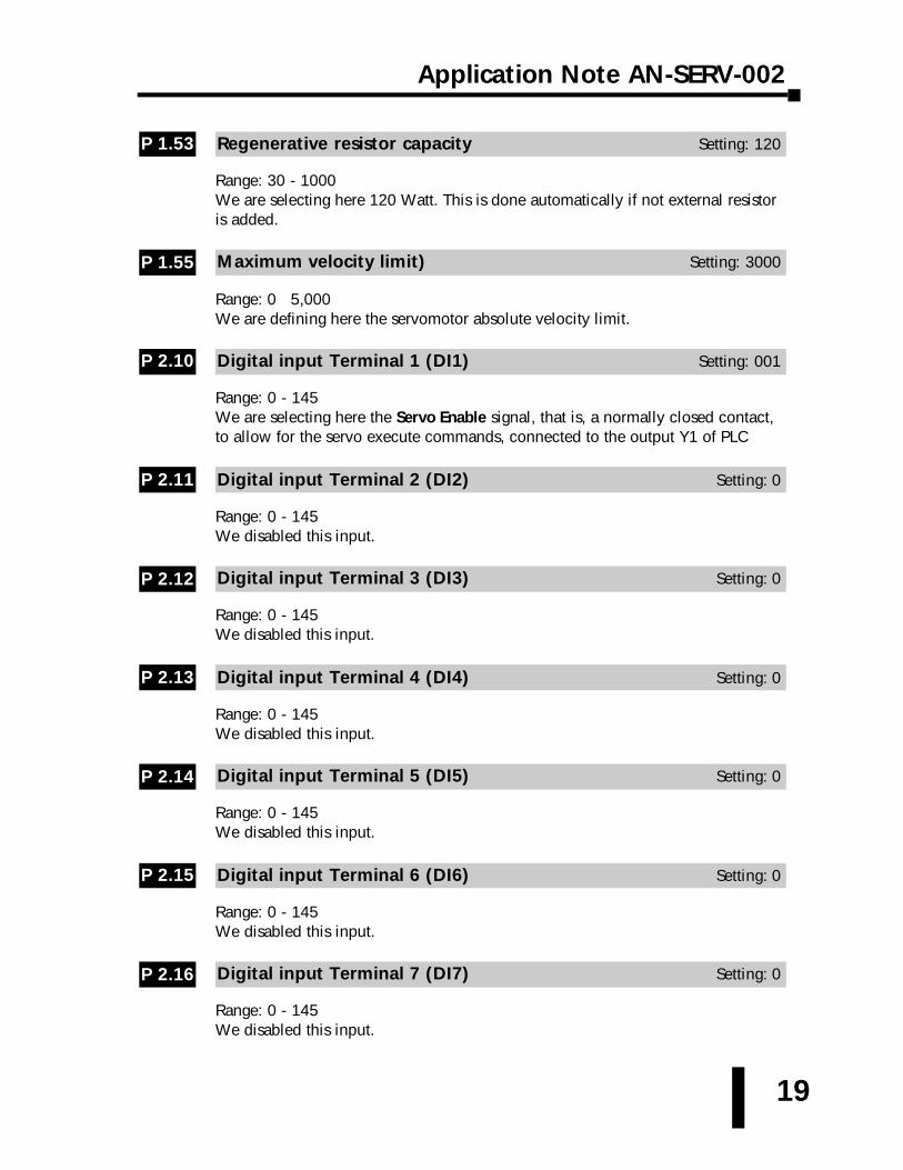
Regenerative resistor capacity Setting: 120
Range: 30 - 1000We are selecting here 120 Watt. This is done automatically if not external resistoris added.
Maximum velocity limit) Setting: 3000
Range: 0 5,000We are defining here the servomotor absolute velocity limit.
Digital input Terminal 1 (DI1) Setting: 001
Range: 0 - 145We are selecting here the Servo Enable signal, that is, a normally closed contact,to allow for the servo execute commands, connected to the output Y1 of PLC
Digital input Terminal 2 (DI2) Setting: 0
Range: 0 - 145We disabled this input.
Digital input Terminal 3 (DI3) Setting: 0
Range: 0 - 145We disabled this input.
Digital input Terminal 4 (DI4) Setting: 0
Range: 0 - 145We disabled this input.
Digital input Terminal 5 (DI5) Setting: 0
Range: 0 - 145We disabled this input.
Digital input Terminal 6 (DI6) Setting: 0
Range: 0 - 145We disabled this input.
Digital input Terminal 7 (DI7) Setting: 0
Range: 0 - 145We disabled this input.
P 2.16
P 2.15
P 2.14
P 2.13
P 2.12
P 2.11
P 2.10
P 1.55
P 1.53
Application Note AN-SERV-002
20
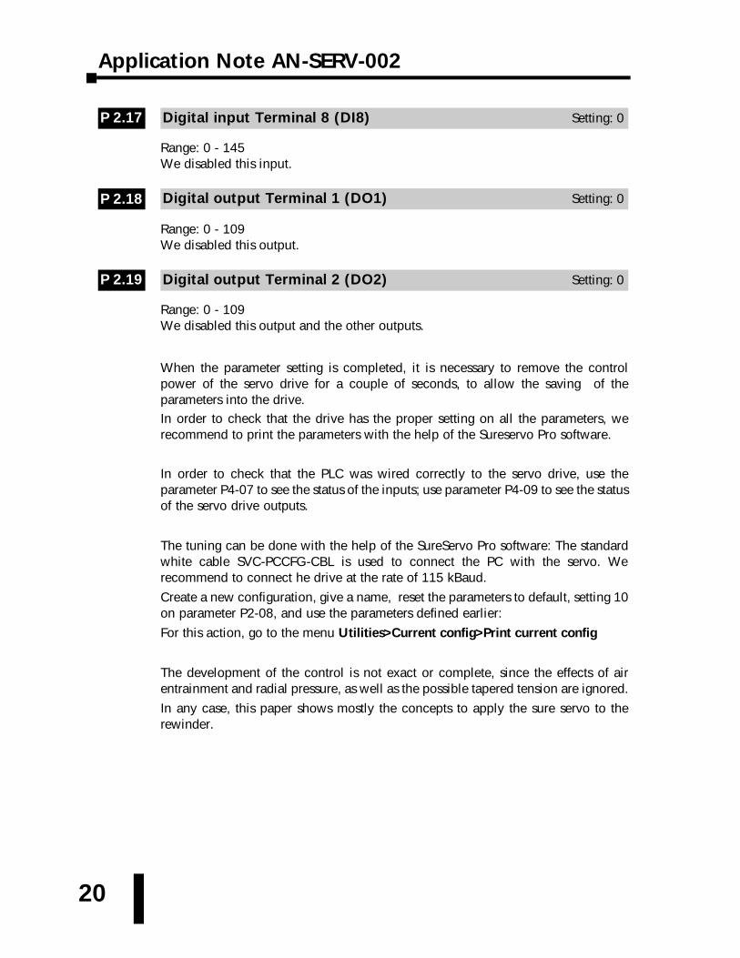
Digital input Terminal 8 (DI8) Setting: 0
Range: 0 - 145We disabled this input.
Digital output Terminal 1 (DO1) Setting: 0
Range: 0 - 109We disabled this output.
Digital output Terminal 2 (DO2) Setting: 0
Range: 0 - 109We disabled this output and the other outputs.
When the parameter setting is completed, it is necessary to remove the controlpower of the servo drive for a couple of seconds, to allow the saving of theparameters into the drive. In order to check that the drive has the proper setting on all the parameters, werecommend to print the parameters with the help of the Sureservo Pro software.
In order to check that the PLC was wired correctly to the servo drive, use theparameter P4-07 to see the status of the inputs; use parameter P4-09 to see the statusof the servo drive outputs.
The tuning can be done with the help of the SureServo Pro software: The standardwhite cable SVC-PCCFG-CBL is used to connect the PC with the servo. Werecommend to connect he drive at the rate of 115 kBaud.
Create a new configuration, give a name, reset the parameters to default, setting 10on parameter P2-08, and use the parameters defined earlier:
For this action, go to the menu Utilities>Current config>Print current config
The development of the control is not exact or complete, since the effects of airentrainment and radial pressure, as well as the possible tapered tension are ignored.
In any case, this paper shows mostly the concepts to apply the sure servo to therewinder.
P 2.19
P 2.18
P 2.17


![Global Serv[0]](https://img.pdfslide.us/doc/110x75/55cf8c7f5503462b138d09a0/global-serv0.jpg)