Embed Size (px)
Citation preview

AR151003 BLF188XR, 352MHz v2.0 — 19 May 2016 Application Report
Document information
Status Company Confidential
Author(s) Hans Kartman
Abstract Measurement report BLF188XR in two amplifier variants With coplanar input and output baluns at 352MHz. NA2270, NA2262, 352MHz, coplanar baluns BLF188XR, high power.

AR151003 BLF188XR 352MHz
AR151003 All information provided in this document is subject to legal disclaimers. © Ampleon The Netherlands B.V. 2015. All rights reserved.
Application Report v2.0 — 19 May 2016 2 of 19
1. Revision History Table 1: Report revisions
2. Contents 1. Revision History .............................................................................................................................................. 2 2. Contents .......................................................................................................................................................... 2 3. List of figures .................................................................................................................................................. 2 4. List of tables .................................................................................................................................................... 3 5. Introduction ..................................................................................................................................................... 3 5.1 General description ....................................................................................................................................... 3 5.2 Test object details ......................................................................................................................................... 3 6. Design .............................................................................................................................................................. 4 6.1 Design considerations ................................................................................................................................... 4 Tests ........................................................................................................................................................................ 4 6.2 Used Test signals.......................................................................................................................................... 4 6.3 Circuit details ................................................................................................................................................ 4 Measurement Results ............................................................................................................................................. 5 6.4 CW/Pulsed – Power Sweep. ......................................................................................................................... 5 PCB Layout, Component list ................................................................................................................................. 7 6.5 PCB Layout drawings .................................................................................................................................... 7 6.6 Therma gap and copper onlays. ................................................................................................................... 9 6.7 Photo’s of the Demo Boards. ...................................................................................................................... 12 6.8 Base plate mechanical drawings. ................................................................................................................ 15 6.9 Conclusion. ................................................................................................................................................. 18 7. Legal information .......................................................................................................................................... 19 7.1 Definitions ................................................................................................................................................... 19 7.2 Disclaimers ................................................................................................................................................. 19 7.3 Trademarks ................................................................................................................................................. 19 7.4 Contact information ..................................................................................................................................... 19
3. List of figures Figure 1 CW (NA2262) ............................. Gain and Efficiency vs Pout (W) ........................................................ 5 Figure 2 CW (NA2270) ............................. Gain and Efficiency vs Pout (W) ........................................................ 5 Figure 3 Pulsed-CW (NA2262) .................. Gain and Efficiency vs Pout (W) ........................................................ 6 Figure 4 Pulsed-CW (NA2270) .................. Gain and Efficiency vs Pout (W) ........................................................ 6 Figure 5 NA2262 ..................................... using a cavity with Therma gap pad. ............................................... 12 Figure 6 NA2270 ..................................... using soldered copper onlays on the balun structure. ..................... 12 Figure 7 NA2270 ..................................... Bottom view ..................................................................................... 13 Figure 8 Baseplate ................................... Version thermal pad output balun.................................................... 13 Figure 9 Baseplate ................................... Version copper platted output balun ................................................ 14 Figure 10 Drawing side view ..................... Version thermal pad output balun.................................................... 15 Figure 11 Drawing top view ...................... Version thermal pad output balun.................................................... 15 Figure 12 Drawing side view ..................... Version thermal pad output balun.................................................... 16 Figure 13 Drawing top view ...................... Version thermal pad output balun.................................................... 16 Figure 14 Drawing bottom side .................. copper onlay bottom side of balun................................................... 17 Figure 15 Drawing top side ....................... one side of copper onlay on topside of the balun ............................ 17
Revision Date Description Author
1.0 20160219 Initial document Hans Kartman
2.0 20160519 Rewritten to Ampleon style Ampleon
AR151003 BLF188XR 352MHz
AR151003 All information provided in this document is subject to legal disclaimers. © Ampleon The Netherlands B.V. 2015. All rights reserved.
Application Report v2.0 — 19 May 2016 3 of 19
4. List of tables Table 1: ..................................................... Report revisions ................................................................................ 2
5. Introduction
5.1 General description This document shows the design and measurement results of two 352 MHz push pull demo amplifiers (Board NA 2270 and NA2262, both with one BLF188XR.) The amplifiers are primarily meant for application in power generators for particle accelerators, but are also suited for other applications.
The amplifiers are only slightly different, mainly in the method chosen to cool the output balun.
NA2262 is an amplifier using a coplanar output balun construction with Therma gap under the balun to conduct heat to the water-cooled baseplate.
NA2270 is an amplifier using a coplanar output balun construction with added copper plating to conduct heat from the balun to the water-cooled baseplate.
Both amplifiers are capable of producing about 1kWatt of output power at efficiencies of 67-68 % at full CW, under pulsed conditions power and efficiency are a bit higher.
Both amplifiers use the same coplanar input balun construction,
The amplifiers are presented in one report because the main difference is the way of cooling the output balun.
5.2 Test object details NA2262.
Transistor type: BLF188XR (Bolted down, using WPS2 compound)
Package: SOT539A
Board: output: 350MHz outp circ V1 using Therma Gap between balun and coldplate
Input: coplanar 352MHz board.
Circuit on full copper cooling base plate, water channel in base plate
NA2270.
Transistor type: BLF188XR (Bolted down, using WPS2 compound)
Package: SOT539A
Board: output: 350MHz output circuit V1 using thick copper plating
Input: coplanar 352MHz board.
Circuit on full copper cooling base plate, water channel in base plate

AR151003 BLF188XR 352MHz
AR151003 All information provided in this document is subject to legal disclaimers. © Ampleon The Netherlands B.V. 2015. All rights reserved.
Application Report v2.0 — 19 May 2016 4 of 19
6. Design
6.1 Design considerations The goal of this amplifier design was an amplifier using BLF188XR capable of producing about 1kWatt of output power (pulsed and full CW) and an efficiency between 65 and 70%, using a coplanar balun construction in the output matching circuit. As this amplifier will run also full CW it should be of thermally adequate design. This report shows the design of two amplifiers for 352MHz using different ways of keeping the temperature of the output balun sufficiently low. The matching network (two wide strip lines) between the drains of the mosfet and the balun is equal for both amplifiers, except for a tuning capacitor. Both amplifiers use CDE mica capacitors in the matching networks to cope with thermal requirements in the matching steps. Drain feed is done by connecting the supply voltage via two heavy air coils.
The two demo circuits:
NA2262 uses Thermagap 976, a thermally conductive pad, between the balun and the cold plate to conduct heat to the water-cooled plate. The Pad lies in a cavity (54x39mm) that is milled out 5mm deep in the copperplate.
NA2270 uses 2mm thick copper plating soldered on the balun strip lines (both sides of board) to conduct the heat to the water cooled cold plate. The balun is positioned above an open recess (54x39mm) in the copper plate.
Both circuits use the same input matching circuit. This circuit is designed as a coplanar balun. The baseplate has a cavity below the balun. No thermal conductive material is used between the PCB and the baseplate.
Bias of the gates is connected by two 47 Ohms resistors and decoupling capacitors.
Tests
6.2 Used Test signals Power/efficiency measurements.
Pulsed, 100uS, Duty Cycle=10% and full CW, Measured at 352 MHz at Vds=50V, Idq=0.1A.
6.3 Circuit details The demo circuits have been designed on Taconic RF35, h=0.76mm, e r=3.5, 2x70um copper. Supply voltage (drain-source) is typical 50V. To set the drain quiescent current, connect the drain supply voltage, then slowly increase Vg until the total. Idq is 100mA. For a typical BLF188XR the Vg voltage will be about 1.7V for this Idq level.
The demo circuit produces an output power of around 1000 Watts (about 3dB compressed), at 67 - 68 % efficiency under full CW operation. The efficiency will be around 70 % under pulsed conditions.

AR151003 BLF188XR 352MHz
AR151003 All information provided in this document is subject to legal disclaimers. © Ampleon The Netherlands B.V. 2015. All rights reserved.
Application Report v2.0 — 19 May 2016 5 of 19
Measurement Results
6.4 CW/Pulsed – Power Sweep. NA2262 CW Power and efficiency, circuit with coplanar balun and Therma Gap pad.
Figure 1 CW (NA2262) Gain and Efficiency vs Pout (W)
NA2270 CW Power and efficiency, circuit with copper plating on the upper and bottom side of the coplanar balun.
Figure 2 CW (NA2270) Gain and Efficiency vs Pout (W)

AR151003 BLF188XR 352MHz
AR151003 All information provided in this document is subject to legal disclaimers. © Ampleon The Netherlands B.V. 2015. All rights reserved.
Application Report v2.0 — 19 May 2016 6 of 19
NA2262 Pulsed power sweep, circuit with coplanar output balun and Therma gap pad.
Figure 3 Pulsed-CW (NA2262) Gain and Efficiency vs Pout (W)
NA2270 Pulsed power sweep, circuit with coplanar output balun and copper plating soldered on both sides of the balun structure.
Figure 4 Pulsed-CW (NA2270) Gain and Efficiency vs Pout (W)
AR151003 BLF188XR 352MHz
AR151003 All information provided in this document is subject to legal disclaimers. © Ampleon The Netherlands B.V. 2015. All rights reserved.
Application Report v2.0 — 19 May 2016 7 of 19
PCB Layout, Component list
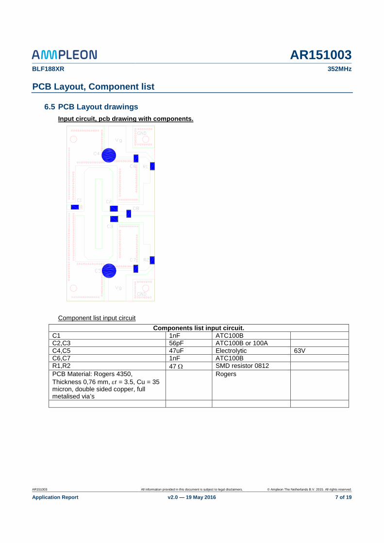
6.5 PCB Layout drawings Input circuit, pcb drawing with components.
Component list input circuit Components list input circuit.
C1 1nF ATC100B C2,C3 56pF ATC100B or 100A C4,C5 47uF Electrolytic 63V C6,C7 1nF ATC100B R1,R2 47 Ω SMD resistor 0812 PCB Material: Rogers 4350, Thickness 0,76 mm, εr = 3.5, Cu = 35 micron, double sided copper, full metalised via’s
Rogers

AR151003 BLF188XR 352MHz
AR151003 All information provided in this document is subject to legal disclaimers. © Ampleon The Netherlands B.V. 2015. All rights reserved.
Application Report v2.0 — 19 May 2016 8 of 19
Output circuit, pcb drawing with components

AR151003 BLF188XR 352MHz
AR151003 All information provided in this document is subject to legal disclaimers. © Ampleon The Netherlands B.V. 2015. All rights reserved.
Application Report v2.0 — 19 May 2016 9 of 19
Components Output circuit. Components list output circuit.
C1,C7 100nF Murata 100V C2,C8 1nF ATC100B C3,C6 68pF CDE min02 C4 47pF CDE min02 C5 22pF CDE min02 C9, C10 470uF electrolitic 63V C11 15pf CDE min02 C12, C13 150pF CDE min02 C14,C15 1nF ATC100B Can be removed
and short circuit C16,C17 4.7uF Murata 100V C18 12pf CDE min02 In circuit with
Thermagap only L1,2 6turns
6mm inner diameter
1.5mm enamel wire Close wound
W1, W2 1.5 sq mm wire
Supply connection
PCB Material: Taconic RF35, Thickness 0,76 mm, εR = 3.5, Cu = 70 micron, double sided copper
Taconic
Copper on-lays (NA2270) 2mm thick copper
On both sides of balun copper pattern
See separate layout drawings
Therma Gap973 pad Size cut pad To fit cavity
6.6 Therma gap and copper onlays. As mentioned the two demo boards use a different way of cooling the coplanar output balun. Because a coplanar balun designed in two layers has no surface contact to the water cooled base plate another means of cooling the structure is needed.
Demo NA2262 uses a pad of Therma Gap between the balun and the cooling plate to conduct the heat. This method of cooling is widely used in other demo boards and also in the customer field it is used. The Base plate drawing at the end of this report shows the cavity in the base plate, 5mm deep , that contains the Therma gap pad. The board rests on the pad, secured by a small screw in the middle of the balun. The Thermal picture shown below shows the temperatures of the board under full (1kW) load power, highest temperature at the balun (right side of picture) is about 90 degrees Celsius, which is quite acceptable. Highest temperature in the entire output circuit is 112 degrees Celsius, which is close to the drains of the transistor.

AR151003 BLF188XR 352MHz
AR151003 All information provided in this document is subject to legal disclaimers. © Ampleon The Netherlands B.V. 2015. All rights reserved.
Application Report v2.0 — 19 May 2016 10 of 19
Specification of Chomerics Therma gap 976 material used in this demo amplifier.

AR151003 BLF188XR 352MHz
AR151003 All information provided in this document is subject to legal disclaimers. © Ampleon The Netherlands B.V. 2015. All rights reserved.
Application Report v2.0 — 19 May 2016 11 of 19
Demo NA2270 uses 2mm thick copper plates soldered to the top side as well as to the bottom side of the balun. Soldering these copper onlay plates to only one of the sides of the balun turned out to be insufficient to lower the temperature of the balun to safe levels. Drawings of the copper onlay plates are given in the drawing section at the end of this report. Both top and bottom side copper plates have a specific area ( near the output connector) where the plate makes good thermal contact to the base plate. The picture below shows the thermal picture of the output circuit under full CW (1kW) load power. Highest temperature at the balun is around 80 degrees Celsius.
For comparison a thermal picture of the coplanar output balun without any cooling structures is shown below. Pload =400Watts (!) CW.

AR151003 BLF188XR 352MHz
AR151003 All information provided in this document is subject to legal disclaimers. © Ampleon The Netherlands B.V. 2015. All rights reserved.
Application Report v2.0 — 19 May 2016 12 of 19
6.7 Photo’s of the Demo Boards. NA2262, using a cavity with Therma gap pad.
Figure 5 NA2262 using a cavity with Therma gap pad.
NA 2270, using soldered copper onlays on the balun structure.
Figure 6 NA2270 using soldered copper onlays on the balun structure.

AR151003 BLF188XR 352MHz
AR151003 All information provided in this document is subject to legal disclaimers. © Ampleon The Netherlands B.V. 2015. All rights reserved.
Application Report v2.0 — 19 May 2016 13 of 19
NA 2270, bottom view of output loop of coplanar balun using soldered copper onlays. (Black paint used for thermal analysis)
Figure 7 NA2270 Bottom view
Baseplate version used for the thermal pad output balun.
Figure 8 Baseplate Version thermal pad output balun

AR151003 BLF188XR 352MHz
AR151003 All information provided in this document is subject to legal disclaimers. © Ampleon The Netherlands B.V. 2015. All rights reserved.
Application Report v2.0 — 19 May 2016 14 of 19
Baseplate version used for the copper plated output balun.
Figure 9 Baseplate Version copper platted output balun

AR151003 BLF188XR 352MHz
AR151003 All information provided in this document is subject to legal disclaimers. © Ampleon The Netherlands B.V. 2015. All rights reserved.
Application Report v2.0 — 19 May 2016 15 of 19
6.8 Base plate mechanical drawings.
Figure 10 Drawing side view Version thermal pad output balun
Figure 11 Drawing top view Version thermal pad output balun

AR151003 BLF188XR 352MHz
AR151003 All information provided in this document is subject to legal disclaimers. © Ampleon The Netherlands B.V. 2015. All rights reserved.
Application Report v2.0 — 19 May 2016 16 of 19
Figure 12 Drawing side view Version thermal pad output balun
Figure 13 Drawing top view Version thermal pad output balun

AR151003 BLF188XR 352MHz
AR151003 All information provided in this document is subject to legal disclaimers. © Ampleon The Netherlands B.V. 2015. All rights reserved.
Application Report v2.0 — 19 May 2016 17 of 19
Layout of copper onlay bottomside of balun.
Figure 14 Drawing bottom side copper onlay bottom side of balun
Layout of one side of copper onlay on topside of the balun.
Figure 15 Drawing top side one side of copper onlay on topside of the balun

AR151003 BLF188XR 352MHz
AR151003 All information provided in this document is subject to legal disclaimers. © Ampleon The Netherlands B.V. 2015. All rights reserved.
Application Report v2.0 — 19 May 2016 18 of 19
6.9 Conclusion. The BLF188XR can produce about 1kW at an efficiency of 65 – 70% on 352MHz. The use of planar baluns at the output and matching circuits is possible by taking special thermal measures.
Using copperplating as well as using thermal conductive pads between the balun and the baseplate are very effective to keep the temperature of the balun at an acceptable level.
The input coplanar balun is very compact.
The described two ways of controlling the temperature of the outputbalun both work well. Temperatures at full output power are within the safe operating range.

AR151003 BLF188XR 352MHz
DOTpro v3 r00 All information provided in this document is subject to legal disclaimers. © Ampleon The Netherlands B.V. 2015. All rights reserved.
Application Report v2.0 — 19 May 2016 19 of 19
7. Legal information
7.1 Definitions Draft — The document is a draft version only. The content is still under internal review and subject to formal approval, which may result in modifications or additions. Ampleon does not give any representations or warranties as to the accuracy or completeness of information included herein and shall have no liability for the consequences of use of such information.
7.2 Disclaimers Limited warranty and liability — Information in this document is believed to be accurate and reliable. However, Ampleon does not give any representations or warranties, expressed or implied, as to the accuracy or completeness of such information and shall have no liability for the consequences of use of such information. Ampleon takes no responsibility for the content in this document if provided by an information source outside of Ampleon.
In no event shall Ampleon be liable for any indirect, incidental, punitive, special or consequential damages (including - without limitation - lost profits, lost savings, business interruption, costs related to the removal or replacement of any products or rework charges) whether or not such damages are based on tort (including negligence), warranty, breach of contract or any other legal theory.
Notwithstanding any damages that customer might incur for any reason whatsoever, Ampleon’s aggregate and cumulative liability towards customer for the products described herein shall be limited in accordance with the Terms and conditions of commercial sale of Ampleon.
Right to make changes — Ampleon reserves the right to make changes to information published in this document, including without limitation specifications and product descriptions, at any time and without notice. This document supersedes and replaces all information supplied prior to the publication hereof.
Suitability for use — Ampleon products are not designed, authorized or warranted to be suitable for use in life support, life-critical or safety-critical systems or equipment, nor in applications where failure or malfunction of an Ampleon product can reasonably be expected to result in personal injury, death or severe property or environmental damage. Ampleon and its suppliers accepts no liability for inclusion and/or use of Ampleon products in such equipment or applications and therefore such inclusion and/or use is at the customer’s own risk.
Applications — Applications that are described herein for any of these products are for illustrative purposes only. Ampleon makes no representation or warranty that such applications will be suitable for the specified use without further testing or modification.
Customers are responsible for the design and operation of their applications and products using Ampleon products, and Ampleon accepts no liability for any assistance with applications or customer product design. It is customer’s sole responsibility to determine whether the Ampleon product is suitable and fit for the customer’s applications and products planned, as well as for the planned application and use of customer’s third party customer(s). Customers should provide appropriate design and operating safeguards to minimize the risks associated with their applications and products.
Ampleon does not accept any liability related to any default, damage, costs or problem which is based on any weakness or default in the customer’s applications or products, or the application or use by customer’s third party customer(s). Customer is responsible for doing all necessary testing for the customer’s applications and products using Ampleon products in order to avoid a default of the applications and the products or of the application or use by customer’s third party customer(s). Ampleon does not accept any liability in this respect.
Export control — This document as well as the item(s) described herein may be subject to export control regulations. Export might require a prior authorization from competent authorities.
7.3 Trademarks Notice: All referenced brands, product names, service names and trademarks are the property of their respective owners.
Any reference or use of any ‘NXP’ trademark in this document or in or on the surface of Ampleon products does not result in any claim, liability or entitlement vis-à-vis the owner of this trademark. Ampleon is no longer part of the NXP group of companies and any reference to or use of the ‘NXP’ trademarks will be replaced by reference to or use of Ampleon’s own trademarks.
7.4 Contact information For more information, please visit: http://www.ampleon.com
For sales office addresses, please visit: http://www.ampleon.com/sales