Embed Size (px)
Citation preview

—RELION®
Substation Merging UnitSMU615Application Manual


Document ID: 1MRS758580Issued: 2019-05-17
Revision: BProduct version: 1.0
© Copyright 2019 ABB. All rights reserved

Copyright
This document and parts thereof must not be reproduced or copied without writtenpermission from ABB, and the contents thereof must not be imparted to a third party,nor used for any unauthorized purpose.
The software or hardware described in this document is furnished under a license andmay be used, copied, or disclosed only in accordance with the terms of such license.
TrademarksABB and Relion are registered trademarks of the ABB Group. All other brand orproduct names mentioned in this document may be trademarks or registeredtrademarks of their respective holders.
WarrantyPlease inquire about the terms of warranty from your nearest ABB representative.
www.abb.com/substationautomation

Disclaimer
The data, examples and diagrams in this manual are included solely for the concept orproduct description and are not to be deemed as a statement of guaranteed properties.All persons responsible for applying the equipment addressed in this manual mustsatisfy themselves that each intended application is suitable and acceptable, includingthat any applicable safety or other operational requirements are complied with. Inparticular, any risks in applications where a system failure and/or product failurewould create a risk for harm to property or persons (including but not limited topersonal injuries or death) shall be the sole responsibility of the person or entityapplying the equipment, and those so responsible are hereby requested to ensure thatall measures are taken to exclude or mitigate such risks.
This product has been designed to be connected and communicate data andinformation via a network interface which should be connected to a secure network.It is the sole responsibility of the person or entity responsible for networkadministration to ensure a secure connection to the network and to take the necessarymeasures (such as, but not limited to, installation of firewalls, application ofauthentication measures, encryption of data, installation of anti virus programs, etc.)to protect the product and the network, its system and interface included, against anykind of security breaches, unauthorized access, interference, intrusion, leakage and/ortheft of data or information. ABB is not liable for any such damages and/or losses.
This document has been carefully checked by ABB but deviations cannot becompletely ruled out. In case any errors are detected, the reader is kindly requested tonotify the manufacturer. Other than under explicit contractual commitments, in noevent shall ABB be responsible or liable for any loss or damage resulting from the useof this manual or the application of the equipment.

Conformity
This product complies with the directive of the Council of the European Communitieson the approximation of the laws of the Member States relating to electromagneticcompatibility (EMC Directive 2014/30/EU) and concerning electrical equipment foruse within specified voltage limits (Low-voltage directive 2014/35/EU). Thisconformity is the result of tests conducted by ABB in accordance with the productstandard EN 60255-26 for the EMC directive, and with the product standards EN60255-1 and EN 60255-27 for the low voltage directive. The product is designed inaccordance with the international standards of the IEC 60255 series.

Table of contents
Section 1 Introduction.......................................................................3This manual........................................................................................ 3Intended audience.............................................................................. 3Product documentation.......................................................................3
Product documentation set............................................................3Document revision history............................................................. 4Related documentation..................................................................4
Symbols and conventions...................................................................4Symbols.........................................................................................4Document conventions..................................................................5Functions, codes and symbols...................................................... 5
Section 2 SMU615 overview............................................................ 9Overview.............................................................................................9
Product version history..................................................................9PCM600 and merging unit's connectivity package version........... 9
Operation functionality......................................................................10Optional functions........................................................................10
Physical hardware............................................................................ 10Local HMI......................................................................................... 11
LEDs............................................................................................12Keypad........................................................................................ 12
Web HMI...........................................................................................13Authorization.....................................................................................14
Audit trail......................................................................................15Communication.................................................................................17
Ethernet redundancy................................................................... 18Process bus.................................................................................20Secure communication................................................................24
Section 3 Merging unit variants......................................................25Application configurations.................................................................25
Addition of control functions for primary devices and the useof binary inputs and outputs........................................................ 26
Connection diagrams........................................................................27Application configuration A............................................................... 31
Applications................................................................................. 31Functions.....................................................................................31
Default I/O connections.......................................................... 31Default disturbance recorder settings.....................................32
Table of contents
SMU615 1Application Manual

Functional diagrams.................................................................... 34Functional diagrams for local and remote control.................. 35Functional diagrams for disturbance recorder........................35Functional diagrams for condition monitoring andsupervision............................................................................. 36Functional diagrams for measurement functions................... 38Functional diagrams for I/O and alarm LEDs......................... 39Functional diagrams for communication.................................41
Application configuration B............................................................... 41Applications................................................................................. 41Functions.....................................................................................42
Default I/O connections.......................................................... 42Default disturbance recorder settings.....................................44
Functional diagrams.................................................................... 47Functional diagrams for local and remote control.................. 48Functional diagrams for disturbance recorder........................48Functional diagrams for condition monitoring andsupervision............................................................................. 49Functional diagrams for control ............................................. 51Functional diagrams for master trip........................................52Functional diagrams for measurement functions................... 53Functional diagrams for I/O and alarm LEDs......................... 55Functional diagrams for communication.................................57
Section 4 Merging unit's physical connections...............................59Inputs................................................................................................59
Energizing inputs.........................................................................59Phase currents....................................................................... 59Residual current..................................................................... 59Phase voltages.......................................................................59Sensor inputs......................................................................... 60
Auxiliary supply voltage input...................................................... 60Binary inputs................................................................................60Optional light sensor inputs......................................................... 61
Outputs............................................................................................. 61Outputs for tripping and controlling..............................................61Outputs for signalling...................................................................62IRF...............................................................................................62
Section 5 Glossary......................................................................... 65
Table of contents
2 SMU615Application Manual

Section 1 Introduction
1.1 This manual
The application manual contains application descriptions sorted per function. Themanual can be used to find out when and for what purpose a typical function can beused.
1.2 Intended audience
This manual addresses the protection and control engineer responsible for planning,pre-engineering and engineering.
The protection and control engineer must be experienced in electrical powerengineering and have knowledge of related technology, such as protection schemesand principles.
1.3 Product documentation
1.3.1 Product documentation set
Pla
nn
ing
&
pu
rch
ase
En
gin
ee
rin
g
Insta
llatio
n
Com
mis
sio
nin
g
Op
era
tio
n
Ma
inte
na
nce
Deco
mm
issio
nin
g,
de
insta
llatio
n &
dis
po
sa
l
Brochure
Product guide
Operation manual
Installation manual
Engineering manual
Technical manual
Application manual
IEC 61850 engineering guide
Cyber security deployment guideline
GUID-46AF8DD4-42E5-466B-840D-478D999D1D6D V1 EN
Figure 1: The intended use of documents during the product life cycle
1MRS758580 B Section 1Introduction
SMU615 3Application Manual

1.3.2 Document revision historyDocument revision/date Product version HistoryA/2017-09-26 1.0 First release
B/2019-05-17 1.0 Content updated
1.3.3 Related documentationName of the document Document IDIEC 61850 Engineering Guide 1MRS758409
Engineering Manual 1MRS758408
Installation Manual 1MRS758405
Operation Manual 1MRS758406
Technical Manual 1MRS758407
Cyber Security Deployment Guideline 1MRS758410
Contact ABB for information on SMU615 related documentation.
1.4 Symbols and conventions
1.4.1 Symbols
The electrical warning icon indicates the presence of a hazard whichcould result in electrical shock.
The warning icon indicates the presence of a hazard which couldresult in personal injury.
The caution icon indicates important information or warning relatedto the concept discussed in the text. It might indicate the presence ofa hazard which could result in corruption of software or damage toequipment or property.
Section 1 1MRS758580 BIntroduction
4 SMU615Application Manual

The information icon alerts the reader of important facts andconditions.
The tip icon indicates advice on, for example, how to design yourproject or how to use a certain function.
Although warning hazards are related to personal injury, it is necessary to understandthat under certain operational conditions, operation of damaged equipment may resultin degraded process performance leading to personal injury or death. Therefore,comply fully with all warning and caution notices.
1.4.2 Document conventions
A particular convention may not be used in this manual.
• Abbreviations and acronyms are spelled out in the glossary. The glossary alsocontains definitions of important terms.
• Menu paths are presented in bold.Select Main menu/Settings.
• Parameter names are shown in italics.The function can be enabled and disabled with the Operation setting.
• Parameter values are indicated with quotation marks.The corresponding parameter values are "On" and "Off".
• Input/output messages and monitored data names are shown in Courier font.• This document assumes that the parameter setting visibility is "Advanced".
1.4.3 Functions, codes and symbolsTable 1: Functions included in the merging unit
Function IEC 61850 IEC 60617 IEC-ANSIMeasurement
Disturbance recorder RDRE1 DR (1) DFR (1)
Three-phase currentmeasurement
CMMXU1 3I (1) 3I (1)
Sequence currentmeasurement
CSMSQI1 I1, I2, I0 (1) I1, I2, I0 (1)
Residual current measurement RESCMMXU1 Io (1) In (1)
Three-phase voltagemeasurement
VMMXU1 3U (1) 3V (1)
Sequence voltagemeasurement
VSMSQI1 U1, U2, U0 (1) V1, V2, V0 (1)
Three-phase power and energymeasurement
PEMMXU1 P, E (1) P, E (1)
Frequency measurement FMMXU1 f (1) f (1)
Table continues on next page
1MRS758580 B Section 1Introduction
SMU615 5Application Manual

Function IEC 61850 IEC 60617 IEC-ANSIIEC 61850-9-2 LE sampledvalue sending
SMVSENDER SMVSENDER SMVSENDER
Condition monitoring and supervision
Circuit-breaker conditionmonitoring
SSCBR1 CBCM (1) CBCM (1)
Trip circuit supervision TCSSCBR1 TCS (1) TCM (1)
TCSSCBR2 TCS (2) TCM (2)
Current circuit supervision CCSPVC1 MCS 3I (1) MCS 3I (1)
Fuse failure supervision SEQSPVC1 FUSEF (1) 60 (1)
Arc detection ARCDSARC1 ARCD (1) AFD (1)
ARCDSARC2 ARCD (2) AFD (2)
ARCDSARC3 ARCD (3) AFD (3)
Control
Circuit-breaker control CBXCBR1 I <-> O CB (1) I <-> O CB (1)
Disconnector control DCXSWI1 I <-> O DCC (1) I <-> O DCC (1)
DCXSWI2 I <-> O DCC (2) I <-> O DCC (2)
Earthing switch control ESXSWI1 I <-> O ESC (1) I <-> O ESC (1)
Disconnector positionindication
DCSXSWI1 I <-> O DC (1) I <-> O DC (1)
DCSXSWI2 I <-> O DC (2) I <-> O DC (2)
Earthing switch indication ESSXSWI1 I <-> O ES (1) I <-> O ES (1)
Other
Minimum pulse timer (2 pcs) TPGAPC1 TP (1) TP (1)
TPGAPC2 TP (2) TP (2)
TPGAPC3 TP (3) TP (3)
TPGAPC4 TP (4) TP (4)
Minimum pulse timer (2 pcs,second resolution)
TPSGAPC1 TPS (1) TPS (1)
Minimum pulse timer (2 pcs,minute resolution)
TPMGAPC1 TPM (1) TPM (1)
Pulse timer (8 pcs) PTGAPC1 PT (1) PT (1)
PTGAPC2 PT (2) PT (2)
Time delay off (8 pcs) TOFGAPC1 TOF (1) TOF (1)
TOFGAPC2 TOF (2) TOF (2)
TOFGAPC3 TOF (3) TOF (3)
TOFGAPC4 TOF (4) TOF (4)
Time delay on (8 pcs) TONGAPC1 TON (1) TON (1)
TONGAPC2 TON (2) TON (2)
TONGAPC3 TON (3) TON (3)
TONGAPC4 TON (4) TON (4)
Table continues on next page
Section 1 1MRS758580 BIntroduction
6 SMU615Application Manual

Function IEC 61850 IEC 60617 IEC-ANSISet-reset (8 pcs) SRGAPC1 SR (1) SR (1)
SRGAPC2 SR (2) SR (2)
SRGAPC3 SR (3) SR (3)
SRGAPC4 SR (4) SR (4)
Move (8 pcs) MVGAPC1 MV (1) MV (1)
MVGAPC2 MV (2) MV (2)
Generic control point (16 pcs) SPCGAPC1 SPC (1) SPC (1)
SPCGAPC2 SPC (2) SPC (2)
Master trip TRPPTRC1 Master Trip (1) 94/86 (1)
TRPPTRC2 Master Trip (2) 94/86 (2)
TRPPTRC3 Master Trip (3) 94/86 (3)
TRPPTRC4 Master Trip (4) 94/86 (4)
TRPPTRC5 Master Trip (5) 94/86 (5)
1MRS758580 B Section 1Introduction
SMU615 7Application Manual

8

Section 2 SMU615 overview
2.1 Overview
SMU615 is a dedicated substation merging unit intended for measuring current andvoltage signals from the instrument transformers and merging them into the standarddigital output format that other devices can further use for various power systemprotection application purposes. SMU615 itself includes no protection functionalitybut it offers the physical interface into the switchgear primary equipment, that is,circuit breaker, disconnector and earthing switch. SMU615 is a member of ABB’sRelion® product family and is characterized by the compactness, simplicity andwithdrawable-unit design.
SMU615 has been designed to unleash the full potential of the IEC 61850 standard forcommunication and interoperability in the digital substations. SMU615 supportsprocess bus according to IEC 61850-9-2 LE with IEEE 1588 v2 time synchronizationand both conventional CT/VT inputs and sensor inputs.
2.1.1 Product version historyProduct version Product history1.0 Product released
2.1.2 PCM600 and merging unit's connectivity package version
• Protection and Control IED Manager PCM600 2.7 or later• SMU615 Connectivity Package Ver.1.0 or later
• Parameter Setting• Signal Monitoring• Event Viewer• Disturbance Handling• Application Configuration• Signal Matrix• IED User Management• IED Compare• Firmware Update• Lifecycle Traceability• Configuration Wizard• Label Printing• IEC 61850 Configuration
1MRS758580 B Section 2SMU615 overview
SMU615 9Application Manual

Contact ABB for information on the latest connectivity package.
2.2 Operation functionality
2.2.1 Optional functions
• Arc detection
2.3 Physical hardware
The merging unit consists of two main parts: plug-in unit and case. The contentdepends on the ordered functionality.
Main unit Slot ID Content Module ID DetailsPlug-inunit
X100 Auxiliary power/BOmodule
PSM0003 orPSM0004
48...250 V DC/100...240 V AC or24...60 V DC2 normally-open PO contacts1 change-over SO contact1 normally-open SO contact2 double-pole PO contacts with TCS1 dedicated internal fault outputcontact
X110 Empty With application configuration A
BI/O module BIO0007 With application configuration B:8 binary inputs3 high-speed SO contacts
X120Orderalternativelyoptions
AI module AIM0013 3 phase voltage inputs (60...210 V)3 phase current inputs (1/5 A)1 residual current input (0.2/1 A)
Case X130 Sensorinputmodule
SIM0002 3 combi sensor inputs (three-phasecurrent and voltage)1 residual current input (0.2/1 A)
X000 Optionalcommunicationmodule
COM0031COM0032COM0033COM0037
See the technical manual for detailsabout the different communicationmodule types.
Rated values of the current and voltage inputs are basic setting parameters of themerging unit. The binary input thresholds are selectable within the range 16…176 VDC by adjusting the binary input setting parameters.
The connection diagrams of different hardware modules are presented in this manual.
Section 2 1MRS758580 BSMU615 overview
10 SMU615Application Manual

See the installation manual for more information about the case andthe plug-in unit.
Table 2: Input/output overview
Appl.conf.
Order code digit Analog channels Binary channels8 9-10 CT VT Combi
sensorBI BO
A A AA 4 3 - - 4PO+2SO
A A BA 1 - 3 - 4PO+2SO
B B AB 4 3 - 8 4PO+2SO+3HSO
B B BB 1 - 3 8 4PO+2SO+3HSO
2.4 Local HMI
The LHMI is used for monitoring the merging unit. The LHMI comprises the pushbutton, LED indicators and communication port.
1MRS758580 B Section 2SMU615 overview
SMU615 11Application Manual

GUID-45DD21AE-B64A-4508-B6DF-FC264C2171DB V2 EN
Figure 2: Example of the LHMI
2.4.1 LEDs
The LHMI includes a dedicated Ready LED indicator and 11 matrix programmableLEDs on front of the LHMI.
The LEDs can be configured with PCM600 and the operation mode can be selected viaWHMI or PCM600.
2.4.2 Keypad
The LHMI keypad contains a push button which is used to acknowledge alarms.
Section 2 1MRS758580 BSMU615 overview
12 SMU615Application Manual

GUID-9101BAA6-AA5B-4747-A817-0FE8C8831B9F V2 EN
Figure 3: LHMI command push button and RJ-45 communication port
2.5 Web HMI
The WHMI allows secure access to the merging unit via a Web browser. When theSecure Communication parameter in the merging unit is activated, the Web server isforced to take a secured (HTTPS) connection to WHMI using TLS encryption. TheWHMI is verified with Internet Explorer 8.0, 9.0, 10.0 and 11.0.
WHMI offers several functions.
• Programmable LEDs and event lists• System supervision• Parameter settings• Measurement display• Disturbance records• Phasor diagram• Importing/Exporting parameters• Report summary
1MRS758580 B Section 2SMU615 overview
SMU615 13Application Manual

GUID-27E59B74-A1B0-48F3-BE04-6ED4B17550A2 V1 EN
Figure 4: Example view of the WHMI
The WHMI can be accessed locally and remotely.
• Locally by connecting the laptop to the merging unit via the front communicationport.
• Remotely over LAN/WAN.
WHMI is enabled by default on the rear port and always enabled (cannot be disabled)on the front port.
If the WHMI is accessed locally via the front communication port, the followingfeatures are available.
• Setting the merging unit to test mode and testing of outputs• Trip circuit lockout reset• Restoring factory settings
2.6 Authorization
Four user categories have been predefined for the WHMI, each with different rightsand default passwords.
The default passwords in the merging unit delivered from the factory can be changedwith Administrator user rights.
Section 2 1MRS758580 BSMU615 overview
14 SMU615Application Manual

Table 3: Predefined user categories
Username User rightsVIEWER Read only access
OPERATOR • Clearing indications
ENGINEER • Changing settings• Clearing event list• Clearing disturbance records• Changing system settings such as IP address, serial baud rate or
disturbance recorder settings• Setting the merging unit to test mode• Selecting language
ADMINISTRATOR • All listed above• Changing password• Factory default activation
For user authorization for PCM600, see PCM600 documentation.
2.6.1 Audit trail
The merging unit offers a large set of event-logging functions. Critical system andmerging unit security-related events are logged to a separate nonvolatile audit trail forthe administrator.
Audit trail is a chronological record of system activities that allows the reconstructionand examination of the sequence of system and security-related events and changes inthe merging unit. Both audit trail events and process related events can be examinedand analyzed in a consistent method with the help of Event List in WHMI and EventViewer in PCM600.
The merging unit stores 2048 audit trail events to the nonvolatile audit trail.Additionally, 1024 process events are stored in a nonvolatile event list. Both the audittrail and event list work according to the FIFO principle. Nonvolatile memory is basedon a memory type which does not need battery backup nor regular component changeto maintain the memory storage.
Audit trail events related to user authorization (login, logout, violation remote andviolation local) are defined according to the selected set of requirements from IEEE1686. The logging is based on predefined user names or user categories. The user audittrail events are accessible with IEC 61850-8-1, PCM600 and WHMI.
1MRS758580 B Section 2SMU615 overview
SMU615 15Application Manual

Table 4: Audit trail events
Audit trail event DescriptionConfiguration change Configuration files changed
Firmware change Firmware changed
Firmware change fail Firmware change failed
Attached to retrofit test case Unit has been attached to retrofit case
Removed from retrofit test case Removed from retrofit test case
Control remote DPC object control remote
Test on Test mode on
Test off Test mode off
Reset trips Reset latched trips (TRPPTRC*)
Time change Time changed directly by the user. Note that this is not usedwhen the merging unit is synchronised properly by theappropriate protocol (IEEE 1588 v2).
View audit log Administrator accessed audit trail
Login Successful login from IEC 61850-8-1 (MMS), WHMI or FTP.
Logout Successful logout from IEC 61850-8-1 (MMS), WHMI or FTP.
Password change Password changed
Firmware reset Reset issued by user or tool
Audit overflow Too many audit events in the time period
Violation remote Unsuccessful login attempt from IEC 61850-8-1 (MMS),WHMI or FTP.
Violation local Unsuccessful login attempt from IEC 61850-8-1 (MMS),WHMI or FTP.
PCM600 Event Viewer can be used to view the audit trail events and process relatedevents. Audit trail events are visible through dedicated Security events view. Sinceonly the administrator has the right to read audit trail, authorization must be used inPCM600. The audit trail cannot be reset, but PCM600 Event Viewer can filter data.Audit trail events can be configured to be visible also in WHMI Event list togetherwith process related events.
To expose the audit trail events through Event list, define theAuthority logging level parameter via Configuration/Authorization/Security. This exposes audit trail events to all users.
Table 5: Comparison of authority logging levels
Audit trail event Authority logging level None Configuration
changeSettings edit All
Configuration change ● ● ●
Firmware change ● ● ●
Table continues on next page
Section 2 1MRS758580 BSMU615 overview
16 SMU615Application Manual

Audit trail event Authority logging levelFirmware change fail ● ● ●
Attached to retrofit test case ● ● ●
Removed from retrofit test case ● ● ●
Control remote ● ●
Test on ● ●
Test off ● ●
Reset trips ● ●
Time change ●
View audit log ●
Login ●
Logout ●
Password change ●
Firmware reset ●
Violation local ●
Violation remote ●
2.7 Communication
The merging unit supports a range of communication protocols including IEC 61850and IEC 61850-9-2 LE. Operational information and controls are available throughthese protocols. However, some communication functionality, for example,horizontal communication between the merging units, is only enabled by the IEC61850 communication protocol.
The IEC 61850 communication implementation supports all monitoring and controlfunctions. Additionally, parameter settings and disturbance recordings can beaccessed using the IEC 61850 protocol. Disturbance recordings are available to anyEthernet-based application in the IEC 60255-24 standard COMTRADE file format.The merging unit can send and receive binary signals from other devices (so-calledhorizontal communication) using the IEC 61850-8-1 GOOSE profile, where thehighest performance class with a total transmission time of 3 ms is supported.Furthermore, the merging unit supports sending of analog values using GOOSEmessaging. The merging unit meets the GOOSE performance requirements fortripping applications in distribution substations, as defined by the IEC 61850standard.
The merging unit can support five simultaneous clients. If PCM600 reserves oneclient connection, only four connections are left for other clients.
All communication connectors, except for the front port connector, are placed onintegrated optional communication modules.
1MRS758580 B Section 2SMU615 overview
SMU615 17Application Manual

2.7.1 Ethernet redundancy
IEC 61850 specifies a network redundancy scheme that improves the systemavailability for substation communication. It is based on two complementaryprotocols defined in the IEC 62439-3:2012 standard: parallel redundancy protocolPRP-1 and high-availability seamless redundancy HSR protocol. Both protocols relyon the duplication of all transmitted information via two Ethernet ports for one logicalnetwork connection. Therefore, both are able to overcome the failure of a link orswitch with a zero-switchover time, thus fulfilling the stringent real-timerequirements for the substation automation horizontal communication and timesynchronization.
PRP specifies that each device is connected in parallel to two local area networks.HSR applies the PRP principle to rings and to the rings of rings to achieve cost-effective redundancy. Thus, each device incorporates a switch element that forwardsframes from port to port.
IEC 62439-3:2012 cancels and replaces the first edition published in2010. These standard versions are also referred to as IEC 62439-3Edition 1 and IEC 62439-3 Edition 2. The merging unit supports IEC62439-3:2012 and it is not compatible with IEC 62439-3:2010.
PRPEach PRP node, called a doubly attached node with PRP (DAN), is attached to twoindependent LANs operated in parallel. These parallel networks in PRP are calledLAN A and LAN B. The networks are completely separated to ensure failureindependence, and they can have different topologies. Both networks operate inparallel, thus providing zero-time recovery and continuous checking of redundancy toavoid communication failures. Non-PRP nodes, called single attached nodes (SANs),are either attached to one network only (and can therefore communicate only withDANs and SANs attached to the same network), or are attached through a redundancybox, a device that behaves like a DAN.
Section 2 1MRS758580 BSMU615 overview
18 SMU615Application Manual

Ethernet switchIEC 61850 PRPEthernet switch
SCADACOM600
GUID-334D26B1-C3BD-47B6-BD9D-2301190A5E9D V3 EN
Figure 5: PRP solution
In case a laptop or a PC workstation is connected as a non-PRP node to one of the PRPnetworks, LAN A or LAN B, it is recommended to use a redundancy box device or anEthernet switch with similar functionality between the PRP network and SAN toremove additional PRP information from the Ethernet frames. In some cases, defaultPC workstation adapters are not able to handle the maximum-length Ethernet frameswith the PRP trailer.
There are different alternative ways to connect a laptop or a workstation as SAN to aPRP network.
• Via an external redundancy box (RedBox) or a switch capable of connecting toPRP and normal networks
• By connecting the node directly to LAN A or LAN B as SAN• By connecting the node to the merging unit's interlink port
HSRHSR applies the PRP principle of parallel operation to a single ring, treating the twodirections as two virtual LANs. For each frame sent, a node, DAN, sends two frames,one over each port. Both frames circulate in opposite directions over the ring and eachnode forwards the frames it receives, from one port to the other. When the originatingnode receives a frame sent to itself, it discards that to avoid loops; therefore, no ringprotocol is needed. Individually attached nodes, SANs, such as laptops and printers,must be attached through a “redundancy box” that acts as a ring element. For example,a merging unit with HSR support can be used as a redundancy box.
1MRS758580 B Section 2SMU615 overview
SMU615 19Application Manual

GUID-207430A7-3AEC-42B2-BC4D-3083B3225990 V3 EN
Figure 6: HSR solution
2.7.2 Process bus
Process bus IEC 61850-9-2 defines the transmission of Sampled Measured Valueswithin the substation automation system. International Users Group created aguideline IEC 61850-9-2 LE that defines an application profile of IEC 61850-9-2 tofacilitate implementation and enable interoperability. Process bus is used fordistributing process data from the primary circuit to all process bus compatibledevices in the local network in a real-time manner. The data can then be processed byany protection relay to perform different protection, automation and control functions.
With process bus the galvanic wiring for sharing busbar voltage value can be replacedwith Ethernet communication. Transmitting measurement samples over process busbrings also higher error detection because the signal transmission is automaticallysupervised. Additional contribution to the higher availability is the possibility to useredundant Ethernet network for transmitting SMV signals.
Section 2 1MRS758580 BSMU615 overview
20 SMU615Application Manual

SMV
Current Sensors
Protection and Control Relay
Substation Merging Unit
GUID-9215CB30-01E3-4D90-B9BA-473FE657DE4F V2 EN
Figure 7: SMU615 sending current measurements as sampled measuredvalues to a protection relay
1MRS758580 B Section 2SMU615 overview
SMU615 21Application Manual

SMV
Protection and Control Relay
Substation Merging Unit
Current Sensors
Voltage Sensor
GUID-1504F322-B34D-409E-A7A9-512FB235921A V2 EN
Figure 8: SMU615 sending voltage measurements as sampled measuredvalues to protection relays
Section 2 1MRS758580 BSMU615 overview
22 SMU615Application Manual

SMV and GOOSE
Smart Substation Control and Protection
Substation Merging Unitwith Binary I/0
Current Sensors
GUID-D8A746E4-6E21-4A4F-A963-7D66FE6A7255 V1 EN
Figure 9: Smart substation control and protection SSC600 with SMU615
The merging unit supports IEC 61850 process bus with sampled values of analogcurrents and voltages. The measured values are transferred as sampled values usingthe IEC 61850-9-2 LE protocol which uses the same physical Ethernet network as theIEC 61850-8-1 station bus. The intended application for sampled values is sharing themeasured voltages and currents from the merging unit to other devices with 9-2support.
The merging units with process bus based applications use IEEE 1588 v2 PrecisionTime Protocol (PTP) according to IEEE C37.238-2011 Power Profile for highaccuracy time synchronization. With IEEE 1588 v2, the cabling infrastructurerequirement is reduced by allowing time synchronization information to betransported over the same Ethernet network as the data communications.
1MRS758580 B Section 2SMU615 overview
SMU615 23Application Manual

IEC 61850 HSR
SMV traffi
c
Backup 1588master clock
Managed HSREthernet switch
PrimaryIEEE 1588 v2 master clock
SecondaryIEEE 1588 v2 master clock(optional)
Managed HSREthernet switch
GUID-7C56BC1F-F1B2-4E74-AB8E-05001A88D53D V6 EN
Figure 10: Example network topology with process bus, redundancy and IEEE1588 v2 time synchronization
The process bus is available for all merging units. See the IEC 61850 engineeringguide for detailed system requirements and configuration details.
2.7.3 Secure communication
The merging unit supports secure communication for WHMI and file transferprotocol. If the Secure Communication parameter is activated, protocols require TLSbased encryption method support from the clients. In this case WHMI must beconnected from a Web browser using the HTTPS protocol and in case of file transferthe client must use FTPS.
Section 2 1MRS758580 BSMU615 overview
24 SMU615Application Manual

Section 3 Merging unit variants
3.1 Application configurations
SMU615 is fully configured to perform its designed primary function in the system asa merging unit and it includes only the relevant functions needed for maximumsimplicity.
SMU615 is available in two alternative application configurations that can be selecteddepending on the amount of additional physical interfaces required. Both theapplication configurations can be selected either with conventional CT/VT inputs orwith sensor inputs.
The merging unit is delivered from the factory with a default configuration includingits internal connections. System level connections for the sampled measured values(SMV) and GOOSE signals are required between the devices.
Table 6: Application configurations
Description Appl. conf.Merging unit with analog inputs A
Merging unit with analog inputs, binary I/O and remote control B
Table 7: Supported functions
Function IEC 61850 A BMeasurement
Disturbance recorder RDRE 1 1
Three-phase current measurement CMMXU 1 1
Sequence current measurement CSMSQI 1 1
Residual current measurement RESCMMXU 1 1
Three-phase voltage measurement VMMXU 1 1
Sequence voltage measurement VSMSQI 1 1
Three-phase power and energy measurement PEMMXU 1 1
Frequency measurement FMMXU 1 1
IEC 61850-9-2 LE sampled value sending SMVSENDER 1 1
Condition monitoring and supervision
Circuit-breaker condition monitoring SSCBR 1
Trip circuit supervision TCSSCBR 21) 2
Current circuit supervision CCSPVC 1 1
Fuse failure supervision SEQSPVC 1 1
Table continues on next page
1MRS758580 B Section 3Merging unit variants
SMU615 25Application Manual

Function IEC 61850 A BArc detection ARCDSARC (3) (3)
Control
Circuit-breaker control CBXCBR 1
Disconnector control DCXSWI 2
Earthing switch control ESXSWI 1
Disconnector position indication DCSXSWI 2
Earthing switch indication ESSXSWI 1
Other
Minimum pulse timer (2 pcs) TPGAPC 4 4
Minimum pulse timer (2 pcs, second resolution) TPSGAPC 1 1
Minimum pulse timer (2 pcs, minute resolution) TPMGAPC 1 1
Pulse timer (8 pcs) PTGAPC 2 2
Time delay off (8 pcs) TOFGAPC 4 4
Time delay on (8 pcs) TONGAPC 4 4
Set-reset (8 pcs) SRGAPC 4 4
Move (8 pcs) MVGAPC 2 2
Generic control point (16 pcs) SPCGAPC 2 2
Master trip TRPPTRC 21) 5
1, 2, ... = Number of included instances. The instances of a function represent the number of identicalfunction blocks available in the application configuration.() = optional
1) Not included in the default application configuration
3.1.1 Addition of control functions for primary devices and the useof binary inputs and outputs
If extra control functions intended for controllable primary devices are added to theconfiguration, additional binary inputs and/or outputs are needed to complement thestandard configuration.
If the number of inputs and/or outputs in a standard configuration is not sufficient, itis possible either to modify the chosen standard configuration in order to release somebinary inputs or binary outputs which have originally been configured for otherpurposes, or to integrate an external input/output module, for example RIO600, to themerging unit.
The external I/O module’s binary inputs and outputs can be used for the less time-critical binary signals of the application. The integration enables releasing someinitially reserved binary inputs and outputs of the merging unit’s standardconfiguration.
The suitability of the merging unit’s binary outputs which have been selected forprimary device control should be carefully verified, for example make and carry and
Section 3 1MRS758580 BMerging unit variants
26 SMU615Application Manual

breaking capacity. If the requirements for the primary device control circuit are notmet, using external auxiliary relays should be considered.
3.2 Connection diagrams
SMU615
X13Light sensor input 1 1)
X14Light sensor input 2 1)
X15Light sensor input 3 1)
16
17
1918
X100
67
89
10
111213
15
14
2
1
3
45
22
212324
SO2
TCS2
PO4
SO1
TCS1
PO3
PO2
PO1
IRF
+
-Uaux
20
1) Order selectable -Optional2) The IED features an automatic short-circuit mechanism in the CT connector when plug-in unit is detached
2)
X120
1
23
45
6
7
89
1011
12
14Io
IL1
IL2
IL3
1/5A
N1/5A
N1/5A
N0.2/1A
N
13
L1L2L3
U1
U2
U360 -
N
210V
60 -
N
210V
60 -
N
210V
S1
S2
P1
P2
P2
P1 S1
S2
a
nN
A
PositiveCurrentDirection
GUID-5B6CEAB8-C670-4D29-B5C4-6C5C13CC03B1 V1 EN
Figure 11: Connection diagram for application configuration A with CT and VTinputs
1MRS758580 B Section 3Merging unit variants
SMU615 27Application Manual

SMU615
X13Light sensor input 1 1)
X14Light sensor input 2 1)
X15Light sensor input 3 1)
16
17
1918
X100
67
89
10
111213
15
14
2
1
3
45
22
212324
SO2
TCS2
PO4
SO1
TCS1
PO3
PO2
PO1
IRF
+
-Uaux
20
1) Order selectable -Optional
L1L2L3
X130
12
X131
45
IL1
78
U1
X132
45
IL2
78
U2
X133
45
IL3
78
U3
Io0.2/1A
N
P2
P1 S1
S2
I
I
I
PositiveCurrentDirection
GUID-DF2B49A0-08C9-4E10-AE14-DD38D51FC780 V1 EN
Figure 12: Connection diagram for application configuration A with sensorinputs
Section 3 1MRS758580 BMerging unit variants
28 SMU615Application Manual

SMU615
X13Light sensor input 1 1)
X14Light sensor input 2 1)
X15Light sensor input 3 1)
16
17
1918
X100
67
89
10
111213
15
14
2
1
3
45
22
212324
SO2
TCS2
PO4
SO1
TCS1
PO3
PO2
PO1
IRF
+
-Uaux
20
2)
X120
1
23
45
6
7
89
1011
12
14Io
IL1
IL2
IL3
1/5A
N1/5A
N1/5A
N0.2/1A
N
13
L1L2L3
U1
U2
U360 -
N
210V
60 -
N
210V
60 -
N
210V
S1
S2
P1
P2
P2
P1 S1
S2
a
nN
A
PositiveCurrentDirection
1) Order selectable -Optional2) The IED features an automatic short-circuit mechanism in the CT connector when plug-in unit is detached
2
3
5
6
7BI 6
BI 5
BI 4
BI 3
BI 2
BI 8
BI 7
10
8
BI 11
4
9
X110
1516
19
23
20
24
HSO3
HSO2
HSO1
X110
GUID-A1993D42-B41B-4926-A8BD-39305AA8F899 V1 EN
Figure 13: Connection diagram for application configuration B with CT and VTinputs
1MRS758580 B Section 3Merging unit variants
SMU615 29Application Manual

SMU615
X13Light sensor input 1 1)
X14Light sensor input 2 1)
X15Light sensor input 3 1)
16
17
1918
X100
67
89
10
111213
15
14
2
1
3
45
22
212324
SO2
TCS2
PO4
SO1
TCS1
PO3
PO2
PO1
IRF
+
-Uaux
20
L1L2L3
X130
12
X131
45
IL1
78
U1
X132
45
IL2
78
U2
X133
45
IL3
78
U3
Io0.2/1A
N
P2
P1 S1
S2
I
I
I
PositiveCurrentDirection
1) Order selectable -Optional
2
3
5
6
7BI 6
BI 5
BI 4
BI 3
BI 2
BI 8
BI 7
10
8
BI 11
4
9
X110
1516
19
23
20
24
HSO3
HSO2
HSO1
X110
GUID-9BFD8DC6-DF81-4513-A106-98C841BBD055 V1 EN
Figure 14: Connection diagram for application configuration B with sensorinputs
Section 3 1MRS758580 BMerging unit variants
30 SMU615Application Manual
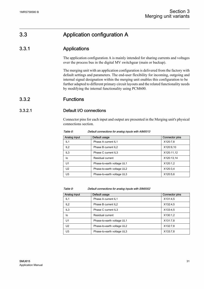
3.3 Application configuration A
3.3.1 Applications
The application configuration A is mainly intended for sharing currents and voltagesover the process bus in the digital MV switchgear (main or backup).
The merging unit with an application configuration is delivered from the factory withdefault settings and parameters. The end-user flexibility for incoming, outgoing andinternal signal designation within the merging unit enables this configuration to befurther adapted to different primary circuit layouts and the related functionality needsby modifying the internal functionality using PCM600.
3.3.2 Functions
3.3.2.1 Default I/O connections
Connector pins for each input and output are presented in the Merging unit's physicalconnections section.
Table 8: Default connections for analog inputs with AIM0013
Analog input Default usage Connector pinsIL1 Phase A current IL1 X120:7,8
IL2 Phase B current IL2 X120:9,10
IL3 Phase C current IL3 X120:11,12
Io Residual current X120:13,14
U1 Phase-to-earth voltage UL1 X120:1,2
U2 Phase-to-earth voltage UL2 X120:3,4
U3 Phase-to-earth voltage UL3 X120:5,6
Table 9: Default connections for analog inputs with SIM0002
Analog input Default usage Connector pinsIL1 Phase A current IL1 X131:4,5
IL2 Phase B current IL2 X132:4,5
IL3 Phase C current IL3 X133:4,5
Io Residual current X130:1,2
U1 Phase-to-earth voltage UL1 X131:7,8
U2 Phase-to-earth voltage UL2 X132:7,8
U3 Phase-to-earth voltage UL3 X133:7,8
1MRS758580 B Section 3Merging unit variants
SMU615 31Application Manual
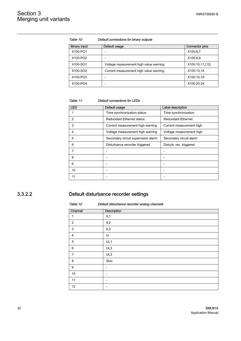
Table 10: Default connections for binary outputs
Binary input Default usage Connector pinsX100-PO1 - X100:6,7
X100-PO2 - X100:8,9
X100-SO1 Voltage measurement high value warning X100:10,11,(12)
X100-SO2 Current measurement high value warning X100:13,14
X100-PO3 - X100:15-19
X100-PO4 - X100:20-24
Table 11: Default connections for LEDs
LED Default usage Label description1 Time synchronization status Time synchronization
2 Redundant Ethernet status Redundant Ethernet
3 Current measurement high warning Current measurement high
4 Voltage measurement high warning Voltage measurement high
5 Secondary circuit supervision alarm Secondary circuit alarm
6 Disturbance recorder triggered Disturb. rec. triggered
7 - -
8 - -
9 - -
10 - -
11 - -
3.3.2.2 Default disturbance recorder settings
Table 12: Default disturbance recorder analog channels
Channel Description1 IL1
2 IL2
3 IL3
4 Io
5 UL1
6 UL2
7 UL3
8 SUo
9 -
10 -
11 -
12 -
Section 3 1MRS758580 BMerging unit variants
32 SMU615Application Manual

Table 13: Default disturbance recorder binary channels
Channel ID text Level trigger mode1 - -
2 - -
3 - -
4 - -
5 - -
6 - -
7 SEQSPVC1_FUSEF_3PH Positive or Rising
8 SEQSPVC1_FUSEF_U Positive or Rising
9 CCSPVC1_FAIL Positive or Rising
10 - -
11 - -
12 - -
13 - -
14 - -
15 - -
16 - -
17 GNRLLTMS1_ALARM Level trigger off
18 GNRLLTMS1_WARNING Level trigger off
19 SCHLCCH1_CH1LIV Level trigger off
20 SCHLCCH1_LNK1LIV Level trigger off
21 - -
22 - -
23 ARCDSARC1_ARC_FLT_DET Positive or Rising
24 ARCDSARC2_ARC_FLT_DET Positive or Rising
25 ARCDSARC3_ARC_FLT_DET Positive or Rising
26 - -
27 - -
28 - -
29 - -
30 - -
31 - -
32 - -
33 - -
34 - -
35 - -
36 - -
37 - -
38 - -
Table continues on next page
1MRS758580 B Section 3Merging unit variants
SMU615 33Application Manual

Channel ID text Level trigger mode39 - -
40 - -
41 - -
42 - -
43 - -
44 - -
45 - -
46 - -
47 - -
48 - -
49 - -
50 - -
51 - -
52 - -
53 - -
54 - -
55 - -
56 - -
57 - -
58 - -
59 - -
60 - -
61 - -
62 - -
63 - -
64 - -
3.3.3 Functional diagrams
The functional diagrams describe the default input, output, alarm LED and function-to-function connections. The default connections can be viewed and changed withPCM600 according to the application requirements.
The analog channels have fixed connections to the different function blocks inside themerging unit’s application configuration. However, the 12 analog channels availablefor the disturbance recorder function are freely selectable as a part of the disturbancerecorder’s parameter settings.
Phase currents are fed to the merging unit from a current transformer or a currentsensor depending on the order options. Residual current is fed to the merging uniteither from residually connected CTs, an external core balance CT or neutral CT.
Section 3 1MRS758580 BMerging unit variants
34 SMU615Application Manual

Phase voltages are fed to the merging unit from a voltage transformer or a voltagesensor depending on the order options
3.3.3.1 Functional diagrams for local and remote control
The functional diagrams describe the merging unit's functionality in detail andaccording to the factory set default connections.
Local & remote control
General logic state TRUE and FALSE
Control
O:25|T:2.5|I:0
CTRL_OFFCTRL_LOCCTRL_STACTRL_REMCTRL_ALL
OFFLOCAL
STATIONREMOTE
ALLBEH_TEST
BEH_BLK
TRUE
NOT
O:24|T:2.5|I:0IN OUT
NOT
O:36|T:2.5|I:3IN OUT
TRUE
TRUE FALSE
FALSE
GUID-8D1CF158-883D-46B5-A104-4D2768DAD288 V1 EN
Figure 15: Local and remote control mode function
3.3.3.2 Functional diagrams for disturbance recorder
Output signals from the condition monitoring and supervision functions are routed totrigger the disturbance recorder or, alternatively, only to be recorded by thedisturbance recorder depending on the parameter settings. Additionally, the selectedsignals from different functions are also connected to the disturbance recorder.
1MRS758580 B Section 3Merging unit variants
SMU615 35Application Manual

RDRE
RDRE1
O:22|T:2.5|I:1
C1C2C3C4C5C6C7C8C9C10C11C12C13C14C15C16C17C18C19C20C21C22C23C24C25C26C27C28C29C30C31C32C33C34C35C36C37C38C39C40C41C42C43C44C45C46C47C48C49C50C51C52C53C54C55C56C57C58C59C60C61C62C63C64
TRIGGERED
SEQSPVC1_FUSEF_3PHSEQSPVC1_FUSEF_U
RCHLCCH1_CHLIVRCHLCCH1_REDCHLIV
CCSPVC1_FAIL
ARCDSARC1_ARC_FLT_DETARCDSARC2_ARC_FLT_DETARCDSARC3_ARC_FLT_DET
RDRE1_TRIGGERED
GUID-9C138747-FCB7-4E91-8723-98F7EE7306AC V1 EN
Figure 16: Disturbance recorder
3.3.3.3 Functional diagrams for condition monitoring and supervision
Failures in the current measuring circuits are detected by CCSPVC1.
The fuse failure supervision function SEQSPVC1 detects failures in the voltagemeasurement circuits. Failures, such as an open MCB, raise an alarm.
Section 3 1MRS758580 BMerging unit variants
36 SMU615Application Manual

Current circuit supervision
Fuse failure supervision
Supervision alarm
CCSPVC1
O:15|T:2.5|I:1
BLOCK FAILALARM CCSPVC1_ALARM
CCSPVC1_FAIL
OR6
O:17|T:2.5|I:1
B1B2B3B4B5B6
OSEQSPVC1_FUSEF_3PHSEQSPVC1_FUSEF_U
CCSPVC1_ALARM
SUPERVISION_ALARM
SEQSPVC1
O:16|T:2.5|I:1
BLOCKCB_CLOSEDDISCON_OPENMINCB_OPEN
FUSEF_3PHFUSEF_U
SEQSPVC1_FUSEF_3PHSEQSPVC1_FUSEF_U
GUID-D3C8D672-A189-4983-BB5A-575FF3A37C62 V1 EN
Figure 17: Current circuit and Fuse failure supervision functions
Three arc detection function stages ARCDSARC1...3 are included as an optionalfunction. The arc detection offers individual function blocks for three arc sensors thatcan be connected to the merging unit. Each arc detection function monitors the lightinformation from an arc and delivers a signal, if an arc is detected.
The output signals from ARCDSARC1...3 are connected to the disturbance recorderfunction block.
ARC detection
ARCDSARC1
O:21|T:2.5|I:1BLOCK ARC_FLT_DET
ARCDSARC2
O:19|T:2.5|I:2BLOCK ARC_FLT_DET
ARCDSARC3
O:20|T:2.5|I:3BLOCK ARC_FLT_DET
ARCDSARC1_ARC_FLT_DET
ARCDSARC2_ARC_FLT_DET
ARCDSARC3_ARC_FLT_DET
GUID-902B3E16-FA05-42A5-9967-50FE0512F746 V1 EN
Figure 18: Arc detection function
1MRS758580 B Section 3Merging unit variants
SMU615 37Application Manual

3.3.3.4 Functional diagrams for measurement functions
The phase current inputs to the merging unit are measured by the three-phase currentmeasurement function CMMXU1. Similarly, the sequence current measurementCSMSQI1 measures the sequence current and the residual current measurementRESCMMXU1 measures the residual current.
The phase voltage inputs to the merging unit are measured by the three-phase voltagemeasurement function VMMXU1. The sequence voltage measurement VSMSQI1measures the sequence voltage.
The measurements can be seen from the WHMI and they are available under theMeasurement menu in the left navigation bar. Based on the settings, function blockscan generate low alarm or warning and high alarm or warning signals for the measuredcurrent values.
The frequency measurement of the power system FMMXU1 and the three-phasepower and energy measurement PEMMXU1 are also available.
CMMXU1
O:27|T:5|I:1
BLOCK HIGH_ALARMHIGH_WARNLOW_WARN
LOW_ALARM
CMMXU1_HIGH_WARN
GUID-8CB08A33-1956-42F7-9980-E5F0EA155C3C V1 EN
Figure 19: Current measurement: Three-phase current measurement
CSMSQI1
O:9|T:5|I:1
GUID-03E2E46D-E2B4-4114-AF1D-AE4B42C1667F V1 EN
Figure 20: Current measurement: Sequence current measurements
RESCMMXU1
O:26|T:5|I:1
BLOCK HIGH_ALARMHIGH_WARN RESCMMXU11_HIGH_WARN
GUID-D213EAB7-459D-455F-89D8-EB8D7836DF23 V1 EN
Figure 21: Current measurement: Residual current measurements
VMMXU1
O:34|T:5|I:1
BLOCK HIGH_ALARMHIGH_WARNLOW_WARN
LOW_ALARM
VMMXU1_HIGH_WARN
GUID-3FA12109-FAD6-4116-AC3A-08923A38F0D4 V1 EN
Figure 22: Voltage measurement: Three-phase voltage measurement
Section 3 1MRS758580 BMerging unit variants
38 SMU615Application Manual

VSMSQI1
O:8|T:5|I:1
GUID-71AA6025-9E4D-49E0-B731-F6B6092EFE7A V1 EN
Figure 23: Voltage measurement: Sequence voltage measurements
FMMXU1
O:41|T:5|I:1
GUID-4D4CCC40-3416-41ED-B2A4-CF78CA765531 V1 EN
Figure 24: Frequency measurement
PEMMXU1
O:37|T:5|I:1RSTACM
GUID-D31E58A1-980E-41A4-80EB-8C3EA16146D0 V1 EN
Figure 25: Three-phase power and energy measurement
3.3.3.5 Functional diagrams for I/O and alarm LEDs
X100-Binary outputs
VMMXU1_HIGH_WARN
CMMXU1_HIGH_WARN
X100 (PSM)_100.X100-SO1
X100 (PSM)_100.X100-SO2
GUID-8FBB2C4C-7D24-4F3F-9264-39B718B159E1 V1 EN
Figure 26: Default binary outputs X100
1MRS758580 B Section 3Merging unit variants
SMU615 39Application Manual

LED1OKALARMRESET
LED2OKALARMRESET
LED3OKALARMRESET
LED4OKALARMRESET
LED5OKALARMRESET
LED6OKALARMRESET
ORB1B2
O
NOTIN OUT
ORB1B2
O
ANDB1B2
O
VMMXU1_HIGH_WARN
CMMXU1_HIGH_WARN
RCHLCCH1_CHLIVRCHLCCH1_REDCHLIV
RDRE1_TRIGGERED
SUPERVISION_ALARM
RESCMMXU11_HIGH_WARN
GNRLLTMS1_EXCLKMSTR
GNRLLTMS1_ALARMGNRLLTMS1_WARNING
GUID-3EE0BCE3-BB92-42FE-BEC3-BD7106D06D19 V1 EN
Figure 27: Default LED connection
Section 3 1MRS758580 BMerging unit variants
40 SMU615Application Manual

3.3.3.6 Functional diagrams for communication
GNRLLTMS1ALARM
WARNINGEXCLKMSTR
RCHLCCH1CHLIV_A
REDCHLIV_BLNKLIV_A
REDLNKLIV_B
SMVSENDER
RCHLCCH1_CHLIVRCHLCCH1_REDCHLIV
GNRLLTMS1_ALARMGNRLLTMS1_WARNINGGNRLLTMS1_EXCLKMSTR
Time synchronization
Redundant Ethernet channel supervision
IEC61850-9-2 LE sampled values sending
GUID-14A47286-A31C-4316-B153-191D5D79C687 V1 EN
Figure 28: Default communication function connection
The IEC 61850-9-2 sampled values sending is enabled by default.
3.4 Application configuration B
3.4.1 Applications
The application configuration B is mainly intended for sharing currents and voltagesover the process bus in the digital MV switchgear (main or backup). Additionally, amerging unit with this application configuration can be used as a breaker control unit(BCU). Application configuration B includes binary inputs and outputs, includingthree high-speed power outputs for fast tripping. Application configuration B is readyconfigured for handling GOOSE inputs from two different devices.
The merging unit with an application configuration is delivered from the factory withdefault settings and parameters. The end-user flexibility for incoming, outgoing andinternal signal designation within the merging unit enables this configuration to befurther adapted to different primary circuit layouts and the related functionality needsby modifying the internal functionality using PCM600.
1MRS758580 B Section 3Merging unit variants
SMU615 41Application Manual

3.4.2 Functions
3.4.2.1 Default I/O connections
Connector pins for each input and output are presented in the Merging unit's physicalconnections section.
Table 14: Default connections for analog inputs with AIM0013
Analog input Default usage Connector pinsIL1 Phase A current IL1 X120:7,8
IL2 Phase B current IL2 X120:9,10
IL3 Phase C current IL3 X120:11,12
Io Residual current X120:13,14
U1 Phase-to-earth voltage UL1 X120:1,2
U2 Phase-to-earth voltage UL2 X120:3,4
U3 Phase-to-earth voltage UL3 X120:5,6
Table 15: Default connections for analog inputs with SIM0002
Analog input Default usage Connector pinsIL1 Phase A current IL1 X131:4,5
IL2 Phase B current IL2 X132:4,5
IL3 Phase C current IL3 X133:4,5
Io Residual current X130:1,2
U1 Phase-to-earth voltage UL1 X131:7,8
U2 Phase-to-earth voltage UL2 X132:7,8
U3 Phase-to-earth voltage UL3 X133:7,8
Table 16: Default connections for binary inputs when the analog input is equipped with AIM0013
Binary input Default usage Connector pinsX110-BI1 Circuit breaker closed position indication X110:1,5
X110-BI2 Circuit breaker open position indication X110:2,5
X110-BI3 Circuit breaker truck in (service position) indication X110:3,5
X110-BI4 Circuit breaker truck out (test position) indication X110:4,5
X110-BI5 MCB open X110-6,10
X110-BI6 Control off X110:7,10
X110-BI7 Earthing switch closed indication X110:8,10
X110-BI8 Earthing switch open indication X110:9,10
Section 3 1MRS758580 BMerging unit variants
42 SMU615Application Manual

Table 17: Default connections for binary inputs when the analog input is equipped with SIM0002
Binary input Default usage Connector pinsX110-BI1 Circuit breaker closed position indication X110:1,5
X110-BI2 Circuit breaker open position indication X110:2,5
X110-BI3 Circuit breaker truck in (service position) indication X110:3,5
X110-BI4 Circuit breaker truck out (test position) indication X110:4,5
X110-BI5 - X110:6,10
X110-BI6 Control off X110:7,10
X110-BI7 Earthing switch closed indication X110:8,10
X110-BI8 Earthing switch open indication X110:9,10
Table 18: Default connections for binary outputs
Binary input Default usage Connector pinsX100-PO1 Close circuit breaker X100:6,7
X100-PO2 - X100:8,9
X100-SO1 Voltage measurement high value warning X100:10,11,(12)
X100-SO2 Current measurement high value warning X100:13,14
X100-PO3 Open circuit breaker/trip coil 1 (including CBXCBR1) X100:15-19
X100-PO4 Open circuit breaker/trip coil 2 X100:20-24
X110-HSO1 Master trip 3 (TRPPTRC3) X110:15,16
X110-HSO2 Master trip 4 (TRPPTRC4) X110:19,20
X110-HSO3 Master trip 5 (TRPPTRC5) X110:23,24
Table 19: Default connections for LEDs
LED Default usage Label description1 Time synchronization status Time synchronization
2 Redundant Ethernet status Redundant Ethernet
3 Current measurement high warning Current measurement high
4 Voltage measurement high warning Voltage measurement high
5 Secondary circuit supervision alarm Secondary circuit alarm
6 Disturbance recorder triggered Disturb. rec. triggered
7 Circuit breaker condition monitoringalarm
CB condition monitoring
8 Feeder in service Feeder in service
9 Feeder out of service Feeder out of service
10 Earthing switch closed Earthing switch closed
11 Circuit breaker trip Trip
1MRS758580 B Section 3Merging unit variants
SMU615 43Application Manual

3.4.2.2 Default disturbance recorder settings
Table 20: Default disturbance recorder analog channels
Channel Description1 IL1
2 IL2
3 IL3
4 Io
5 UL1
6 UL2
7 UL3
8 SUo
9 -
10 -
11 -
12 -
Table 21: Default disturbance recorder binary channels when the analog input is equipped withAIM0013
Channel ID text Level trigger mode1 CB Closed Level trigger off
2 CB Open Level trigger off
3 DC1 Closed Level trigger off
4 DC1 Open Level trigger off
5 ES Closed Level trigger off
6 ES Open Level trigger off
7 SEQSPVC1_FUSEF_3PH Positive or Rising
8 SEQSPVC1_FUSEF_U Positive or Rising
9 CCSPVC1_FAIL Positive or Rising
10 TRPPTRC1_TRIP Positive or Rising
11 TRPPTRC2_TRIP Positive or Rising
12 TRPPTRC3_TRIP Positive or Rising
13 TRPPTRC4_TRIP Positive or Rising
14 TRPPTRC5_TRIP Positive or Rising
15 CONTROL OFF Level trigger off
16 MCB open Level trigger off
17 GNRLLTMS1_ALARM Level trigger off
18 GNRLLTMS1_WARNING Level trigger off
19 SCHLCCH1_CH1LIV Level trigger off
20 SCHLCCH1_LNK1LIV Level trigger off
Table continues on next page
Section 3 1MRS758580 BMerging unit variants
44 SMU615Application Manual

Channel ID text Level trigger mode21 CBXCBR1_CLOSE_COMMAND Level trigger off
22 CBXCBR1_OPEN_COMMAND Level trigger off
23 ARCDSARC1_ARC_FLT_DET Positive or Rising
24 ARCDSARC2_ARC_FLT_DET Positive or Rising
25 ARCDSARC3_ARC_FLT_DET Positive or Rising
26 - -
27 - -
28 - -
29 - -
30 - -
31 - -
32 - -
33 GOOSERCV_BIN 0_MASTER_TRIP 1 Level trigger off
34 GOOSERCV_BIN 1_MASTER_TRIP 2 Level trigger off
35 GOOSERCV_BIN 2_MASTER_TRIP 3 Level trigger off
36 GOOSERCV_BIN 3_MASTER_TRIP 4 Level trigger off
37 GOOSERCV_BIN 4_MASTER_TRIP 5 Level trigger off
38 GOOSERCV_BIN 5_LOCKOUT_RESET Level trigger off
39 GOOSERCV_BIN 6_AU_OPEN Level trigger off
40 GOOSERCV_BIN 7_AU_CLOSE Level trigger off
41 GOOSERCV_BIN 10_MASTER_TRIP 1 Level trigger off
42 GOOSERCV_BIN 11_MASTER_TRIP 2 Level trigger off
43 GOOSERCV_BIN 12_MASTER_TRIP 3 Level trigger off
44 GOOSERCV_BIN 13_MASTER_TRIP 4 Level trigger off
45 GOOSERCV_BIN 14_MASTER_TRIP 5 Level trigger off
46 GOOSERCV_BIN 15_LOCKOUT_RESET Level trigger off
47 GOOSERCV_BIN 16_AU_OPEN Level trigger off
48 GOOSERCV_BIN 17_AU_CLOSE Level trigger off
49 - -
50 - -
51 - -
52 - -
53 - -
54 - -
55 - -
56 - -
57 - -
58 - -
59 - -
Table continues on next page
1MRS758580 B Section 3Merging unit variants
SMU615 45Application Manual

Channel ID text Level trigger mode60 - -
61 - -
62 - -
63 - -
64 - -
Table 22: Default disturbance recorder binary channels when the analog input is equipped withSIM0002
Channel ID text Level trigger mode1 CB Closed Level trigger off
2 CB Open Level trigger off
3 DC1 Closed Level trigger off
4 DC1 Open Level trigger off
5 ES Closed Level trigger off
6 ES Open Level trigger off
7 SEQSPVC1_FUSEF_3PH Positive or Rising
8 SEQSPVC1_FUSEF_U Positive or Rising
9 CCSPVC1_FAIL Positive or Rising
10 TRPPTRC1_TRIP Positive or Rising
11 TRPPTRC2_TRIP Positive or Rising
12 TRPPTRC3_TRIP Positive or Rising
13 TRPPTRC4_TRIP Positive or Rising
14 TRPPTRC5_TRIP Positive or Rising
15 CONTROL OFF Level trigger off
16 - -
17 GNRLLTMS1_ALARM Level trigger off
18 GNRLLTMS1_WARNING Level trigger off
19 SCHLCCH1_CH1LIV Level trigger off
20 SCHLCCH1_LNK1LIV Level trigger off
21 CBXCBR1_CLOSE_COMMAND Level trigger off
22 CBXCBR1_OPEN_COMMAND Level trigger off
23 ARCDSARC1_ARC_FLT_DET Positive or Rising
24 ARCDSARC2_ARC_FLT_DET Positive or Rising
25 ARCDSARC3_ARC_FLT_DET Positive or Rising
26 - -
27 - -
28 - -
29 - -
30 - -
Table continues on next page
Section 3 1MRS758580 BMerging unit variants
46 SMU615Application Manual

Channel ID text Level trigger mode31 - -
32 - -
33 GOOSERCV_BIN 0_MASTER_TRIP 1 Level trigger off
34 GOOSERCV_BIN 1_MASTER_TRIP 2 Level trigger off
35 GOOSERCV_BIN 2_MASTER_TRIP 3 Level trigger off
36 GOOSERCV_BIN 3_MASTER_TRIP 4 Level trigger off
37 GOOSERCV_BIN 4_MASTER_TRIP 5 Level trigger off
38 GOOSERCV_BIN 5_LOCKOUT_RESET Level trigger off
39 GOOSERCV_BIN 6_AU_OPEN Level trigger off
40 GOOSERCV_BIN 7_AU_CLOSE Level trigger off
41 GOOSERCV_BIN 10_MASTER_TRIP 1 Level trigger off
42 GOOSERCV_BIN 11_MASTER_TRIP 2 Level trigger off
43 GOOSERCV_BIN 12_MASTER_TRIP 3 Level trigger off
44 GOOSERCV_BIN 13_MASTER_TRIP 4 Level trigger off
45 GOOSERCV_BIN 14_MASTER_TRIP 5 Level trigger off
46 GOOSERCV_BIN 15_LOCKOUT_RESET Level trigger off
47 GOOSERCV_BIN 16_AU_OPEN Level trigger off
48 GOOSERCV_BIN 17_AU_CLOSE Level trigger off
49 - -
50 - -
51 - -
52 - -
53 - -
54 - -
55 - -
56 - -
57 - -
58 - -
59 - -
60 - -
61 - -
62 - -
63 - -
64 - -
3.4.3 Functional diagrams
The functional diagrams describe the default input, output, alarm LED and function-to-function connections. The default connections can be viewed and changed withPCM600 according to the application requirements.
1MRS758580 B Section 3Merging unit variants
SMU615 47Application Manual

The analog channels have fixed connections to the different function blocks inside themerging unit’s application configuration. However, the 12 analog channels availablefor the disturbance recorder function are freely selectable as a part of the disturbancerecorder’s parameter settings.
Phase currents are fed to the merging unit from a current transformer or a currentsensor depending on the order options. Residual current is fed to the merging uniteither from residually connected CTs, an external core balance CT or neutral CT.
Phase voltages are fed to the merging unit from a voltage transformer or a voltagesensor depending on the order options
3.4.3.1 Functional diagrams for local and remote control
The functional diagrams describe the merging unit's functionality in detail andaccording to the factory set default connections.
ControlCTRL_OFFCTRL_LOCCTRL_STACTRL_REMCTRL_ALL
OFFLOCAL
STATIONREMOTE
ALLBEH_TEST
BEH_BLK
NOTIN OUT
ORB1B2
O
X110_BI6_CONTROL_OFF
GOOSERCV_BIN 8_L/R_MODEGOOSERCV_BIN 18_L/R_MODE
Control_OFF
Local & remote control
GUID-AAD693CE-9F15-426B-95C4-5BAE6815A13F V1 EN
Figure 29: Local and remote control mode function
3.4.3.2 Functional diagrams for disturbance recorder
Output signals from the condition monitoring and supervision functions are routed totrigger the disturbance recorder or, alternatively, only to be recorded by thedisturbance recorder depending on the parameter settings. Additionally, the selectedsignals from different functions are also connected to the disturbance recorder.
Section 3 1MRS758580 BMerging unit variants
48 SMU615Application Manual
RDRE with AIM0013 MODULE option
RDRE1
O:52|T:2.5|I:1
C1C2C3C4C5C6C7C8C9C10C11C12C13C14C15C16C17C18C19C20C21C22C23C24C25C26C27C28C29C30C31C32C33C34C35C36C37C38C39C40C41C42C43C44C45C46C47C48C49C50C51C52C53C54C55C56C57C58C59C60C61C62C63C64
TRIGGERED
X110_BI6_CONTROL_OFF
TRPPTRC1_TRIPTRPPTRC2_TRIP
CBXCBR1_EXE_OPCBXCBR1_EXE_CL
TRPPTRC3_TRIPTRPPTRC4_TRIPTRPPTRC5_TRIP
GOOSERCV_BIN 5_LOCKOUT_RESET
GOOSERCV_BIN 15_LOCKOUT_RESET
X110_BI2_CB_OPENX110_BI1_CB_CLOSED
GOOSERCV_BIN 6_AU_OPEN
GOOSERCV_BIN 16_AU_OPEN
GOOSERCV_BIN 7_AU_CLOSE
GOOSERCV_BIN 17_AU_CLOSE
X110_BI4_CB_TRUCK_OUT/TESTX110_BI3_CB_TRUCK_IN/SERVICE
X110_BI8_ES_OPENX110_BI7_ES_CLOSED
GOOSERCV_BIN 0_MASTER_TRIP 1GOOSERCV_BIN 1_MASTER_TRIP 2GOOSERCV_BIN 2_MASTER_TRIP 3GOOSERCV_BIN 3_MASTER_TRIP 4GOOSERCV_BIN 4_MASTER_TRIP 5
GOOSERCV_BIN 10_MASTER_TRIP 1GOOSERCV_BIN 11_MASTER_TRIP 2GOOSERCV_BIN 12_MASTER_TRIP 3GOOSERCV_BIN 13_MASTER_TRIP 4GOOSERCV_BIN 14_MASTER_TRIP 5
SEQSPVC1_FUSEF_3PHSEQSPVC1_FUSEF_U
X110_BI5_MCB_OPEN
RCHLCCH1_CHLIVRCHLCCH1_REDCHLIV
CCSPVC1_FAIL
ARCDSARC1_ARC_FLT_DETARCDSARC2_ARC_FLT_DETARCDSARC3_ARC_FLT_DET
RDRE1_TRIGGERED
RDRE with SIM0002 MODULE option
RDRE1
O:52|T:2.5|I:1
C1C2C3C4C5C6C7C8C9C10C11C12C13C14C15C16C17C18C19C20C21C22C23C24C25C26C27C28C29C30C31C32C33C34C35C36C37C38C39C40C41C42C43C44C45C46C47C48C49C50C51C52C53C54C55C56C57C58C59C60C61C62C63C64
TRIGGERED
X110_BI6_CONTROL_OFF
TRPPTRC1_TRIPTRPPTRC2_TRIP
CBXCBR1_EXE_OPCBXCBR1_EXE_CL
TRPPTRC3_TRIPTRPPTRC4_TRIPTRPPTRC5_TRIP
GOOSERCV_BIN 5_LOCKOUT_RESET
GOOSERCV_BIN 15_LOCKOUT_RESET
X110_BI2_CB_OPENX110_BI1_CB_CLOSED
GOOSERCV_BIN 6_AU_OPEN
GOOSERCV_BIN 16_AU_OPEN
GOOSERCV_BIN 7_AU_CLOSE
GOOSERCV_BIN 17_AU_CLOSE
X110_BI4_CB_TRUCK_OUT/TESTX110_BI3_CB_TRUCK_IN/SERVICE
X110_BI8_ES_OPENX110_BI7_ES_CLOSED
GOOSERCV_BIN 0_MASTER_TRIP 1
GOOSERCV_BIN 10_MASTER_TRIP 1
GOOSERCV_BIN 1_MASTER_TRIP 2GOOSERCV_BIN 2_MASTER_TRIP 3GOOSERCV_BIN 3_MASTER_TRIP 4GOOSERCV_BIN 4_MASTER_TRIP 5
GOOSERCV_BIN 11_MASTER_TRIP 2GOOSERCV_BIN 12_MASTER_TRIP 3GOOSERCV_BIN 13_MASTER_TRIP 4GOOSERCV_BIN 14_MASTER_TRIP 5
SEQSPVC1_FUSEF_3PHSEQSPVC1_FUSEF_U
RCHLCCH1_CHLIVRCHLCCH1_REDCHLIV
CCSPVC1_FAIL
ARCDSARC1_ARC_FLT_DETARCDSARC2_ARC_FLT_DETARCDSARC3_ARC_FLT_DET
RDRE1_TRIGGERED
GUID-6C973765-A879-4A77-BD52-16CE69297B9A V1 EN
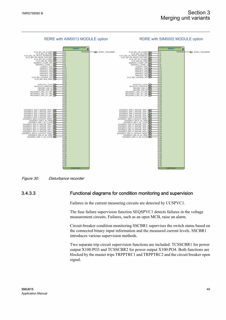
Figure 30: Disturbance recorder
3.4.3.3 Functional diagrams for condition monitoring and supervision
Failures in the current measuring circuits are detected by CCSPVC1.
The fuse failure supervision function SEQSPVC1 detects failures in the voltagemeasurement circuits. Failures, such as an open MCB, raise an alarm.
Circuit-breaker condition monitoring SSCBR1 supervises the switch status based onthe connected binary input information and the measured current levels. SSCBR1introduces various supervision methods.
Two separate trip circuit supervision functions are included: TCSSCBR1 for poweroutput X100:PO3 and TCSSCBR2 for power output X100:PO4. Both functions areblocked by the master trips TRPPTRC1 and TRPPTRC2 and the circuit breaker opensignal.
1MRS758580 B Section 3Merging unit variants
SMU615 49Application Manual

It is assumed that there is no external resistor in the circuit breaker'stripping coil circuit connected in parallel with the circuit breaker'snormally open auxiliary contact.
TCSSCBR1
O:56|T:5|I:1BLOCK ALARM
TCSSCBR2
O:57|T:5|I:2BLOCK ALARM
SEQSPVC1
O:50|T:2.5|I:1
BLOCKCB_CLOSEDDISCON_OPENMINCB_OPEN
FUSEF_3PHFUSEF_U
OR6
O:58|T:2.5|I:1
B1B2B3B4B5B6
O
OR6
O:55|T:2.5|I:2
B1B2B3B4B5B6
O
CCSPVC1
O:45|T:2.5|I:1
BLOCK FAILALARM
SSCBR1
O:60|T:5|I:1
BLOCKPOSOPENPOSCLOSEOPEN_CB_EXECLOSE_CB_EXEPRES_ALM_INPRES_LO_INSPR_CHR_STSPR_CHRRST_IPOWRST_CB_WEARRST_TRV_TRST_SPR_T
TRV_T_OP_ALMTRV_T_CL_ALMSPR_CHR_ALM
OPR_ALMOPR_LO
IPOW_ALMIPOW_LO
CB_LIFE_ALMMON_ALM
PRES_ALMPRES_LO
OPENPOSINVALIDPOSCLOSEPOS
OR6
O:62|T:2.5|I:4
B1B2B3B4B5B6
O
OR6
O:61|T:2.5|I:5
B1B2B3B4B5B6
O
OR
O:63|T:2.5|I:9
B1B2
O
TRPPTRC1_TRIPTRPPTRC2_TRIP
X110_BI2_CB_OPEN
X110_BI2_CB_OPENX110_BI1_CB_CLOSED
X110_BI1_CB_CLOSEDSEQSPVC1_FUSEF_3PH
SEQSPVC1_FUSEF_3PH
SEQSPVC1_FUSEF_U
SEQSPVC1_FUSEF_U
TCSSCBR1_ALARM
TCSSCBR1_ALARM
TCSSCBR2_ALARM
TCSSCBR2_ALARM
CCSPVC1_ALARM
CCSPVC1_ALARM
X110_BI5_MCB_OPEN
CCSPVC1_FAIL
SUPERVISION_ALARM
CB_CONDITION_MONITORING
Trip circuit supervision function
Current circuit supervision
Fuse failure supervision with AIM0013 MODULE option
Supervision alarm
CB condition monitoring
SEQSPVC1
O:50|T:2.5|I:1
BLOCKCB_CLOSEDDISCON_OPENMINCB_OPEN
FUSEF_3PHFUSEF_UX110_BI1_CB_CLOSED
SEQSPVC1_FUSEF_3PHSEQSPVC1_FUSEF_U
Fuse failure supervision with SIM0002 MODULE option
GUID-D57B66CC-AE68-49F5-BB05-46288CAC1FC8 V1 EN
Figure 31: Current circuit and Fuse failure supervision functions
Three arc detection function stages ARCDSARC1...3 are included as an optionalfunction. The arc detection offers individual function blocks for three arc sensors thatcan be connected to the merging unit. Each arc detection function monitors the lightinformation from an arc and delivers a signal, if an arc is detected.
The output signals from ARCDSARC1...3 are connected to the disturbance recorderfunction block.
Section 3 1MRS758580 BMerging unit variants
50 SMU615Application Manual

ARCDSARC1
O:49|T:2.5|I:1BLOCK ARC_FLT_DET
ARCDSARC2
O:46|T:2.5|I:2BLOCK ARC_FLT_DET
ARCDSARC3
O:48|T:2.5|I:3BLOCK ARC_FLT_DET
ARCDSARC1_ARC_FLT_DET
ARCDSARC2_ARC_FLT_DET
ARCDSARC3_ARC_FLT_DET
ARC detection
GUID-3048AEC7-3776-4D36-8488-9A0EC00DD5A5 V1 EN
Figure 32: Arc detection function
3.4.3.4 Functional diagrams for control
DCSXSWI1 and ESSXSWI1 are of status only type. By default, the status only blocksare connected in the application configuration. The disconnector (CB truck) and lineside earthing switch status information is connected to DCSXSWI1 and ESSXSWI1.
The circuit breaker closing is enabled when the ENA_CLOSE input is activated. Theinput can be activated by the configuration logic, which is a combination of thedisconnector or breaker truck and earthing switch position statuses and the status ofthe trip logics. The circuit breaker opening command is given via communication byactivating the AU_OPEN input. The circuit breaker closing command is given viacommunication by activating the AU_CLOSE input. The circuit breaker opening orclosing command is blocked once the BLK_OPEN or BLK_CLOSE input has beenactivated by the Control_OFF signal. By default, Control_OFF is connected to X110-BI6.
The OKPOS output from DCSXSWI defines if the disconnector or breaker truck isdefinitely either open (in test position) or closed (in service position). This output,together with the earthing switch opening and non-active trip signals, activates theclose-enabling signal to the circuit breaker control function block. The openingoperation for circuit breaker is always enabled.
1MRS758580 B Section 3Merging unit variants
SMU615 51Application Manual

CBXCBR1POSOPENPOSCLOSEENA_OPENENA_CLOSEBLK_OPENBLK_CLOSEAU_OPENAU_CLOSETRIPSYNC_OKSYNC_ITL_BYP
SELECTEDEXE_OPEXE_CL
OP_REQCL_REQ
OPENPOSCLOSEPOS
OKPOSOPEN_ENAD
CLOSE_ENAD
DCSXSWI1POSOPENPOSCLOSE
OPENPOSCLOSEPOS
OKPOS
ESSXSWI1POSOPENPOSCLOSE
OPENPOSCLOSEPOS
OKPOS
ORB1B2
O
ORB1B2
O
AND6B1B2B3B4B5B6
O
NOTIN OUT
CBXCBR1_EXE_OPCBXCBR1_EXE_CL
X110_BI2_CB_OPENX110_BI1_CB_CLOSED
GOOSERCV_BIN 6_AU_OPENGOOSERCV_BIN 16_AU_OPEN
GOOSERCV_BIN 7_AU_CLOSEGOOSERCV_BIN 17_AU_CLOSE
X110_BI4_CB_TRUCK_OUT/TEST
X110_BI8_ES_OPENX110_BI7_ES_CLOSED
GENERAL_AU_OPEN
GENERAL_AU_OPEN
GENERAL_AU_CLOSE
GENERAL_AU_CLOSE
DCSXSWI1_OKPOS
DCSXSWI1_OKPOS
ESSXSWI1_OPENPOS
ESSXSWI1_OPENPOS
GENERAL_TRPPTRC_TRIP
CLOSE_ENA
CLOSE_ENAControl_OFF
Circuit breaker 1
DC1
ES1
GUID-7E09019A-F64D-48B9-B3A3-DBBB64A01724 V1 EN
Figure 33: Control functions
3.4.3.5 Functional diagrams for master trip
The GOOSE binary input signals are connected to the five trip logics TRPPTRC1…TRPPTRC5. The outputs of trip logic functions TRPPTRC1 and TRPPTRC2 areavailable at binary outputs X100:PO3 and X100:PO4. The outputs of trip logicfunctions TRPPTRC3...TRPPTRC5 are available at binary outputs X110:HSO1,X110:HSO2 and X110:HSO3.
The trip logic functions are provided with lockout and latching function, eventgeneration and trip signal duration setting. If the lockout operation mode is selected,the binary input GENERAL_LOCKOUT_RESET has been assigned to theRST_LKOUT input to enable external reset with the connected GOOSE signal.
Section 3 1MRS758580 BMerging unit variants
52 SMU615Application Manual

TRPPTRC1
O:33|T:2.5|I:1
BLOCKOPERATERST_LKOUT
TRIPCL_LKOUT
TRPPTRC2
O:31|T:2.5|I:2
BLOCKOPERATERST_LKOUT
TRIPCL_LKOUT
TRPPTRC3
O:32|T:2.5|I:3
BLOCKOPERATERST_LKOUT
TRIPCL_LKOUT
TRPPTRC4
O:29|T:2.5|I:4
BLOCKOPERATERST_LKOUT
TRIPCL_LKOUT
TRPPTRC5
O:30|T:2.5|I:5
BLOCKOPERATERST_LKOUT
TRIPCL_LKOUT
OR6
O:34|T:2.5|I:0
B1B2B3B4B5B6
O
OR
O:28|T:2.5|I:1
B1B2
O
OR
O:26|T:2.5|I:2
B1B2
O
OR
O:27|T:2.5|I:3
B1B2
O
OR
O:23|T:2.5|I:4
B1B2
O
OR
O:25|T:2.5|I:5
B1B2
O
TRPPTRC1_TRIP
TRPPTRC1_TRIP
TRPPTRC2_TRIP
TRPPTRC2_TRIP
TRPPTRC3_TRIP
TRPPTRC3_TRIP
TRPPTRC4_TRIP
TRPPTRC4_TRIP
TRPPTRC5_TRIP
TRPPTRC5_TRIP
GOOSERCV_BIN 0_MASTER_TRIP 1
GOOSERCV_BIN 1_MASTER_TRIP 2
GOOSERCV_BIN 2_MASTER_TRIP 3
GOOSERCV_BIN 3_MASTER_TRIP 4
GOOSERCV_BIN 4_MASTER_TRIP 5
GOOSERCV_BIN 10_MASTER_TRIP 1
GOOSERCV_BIN 11_MASTER_TRIP 2
GOOSERCV_BIN 12_MASTER_TRIP 3
GOOSERCV_BIN 13_MASTER_TRIP 4
GOOSERCV_BIN 14_MASTER_TRIP 5
GENERAL_LOCKOUT_RESET
GENERAL_LOCKOUT_RESET
GENERAL_LOCKOUT_RESET
GENERAL_LOCKOUT_RESET
GENERAL_LOCKOUT_RESET
GENERAL_TRPPTRC_TRIP
GUID-878F3017-E33B-4D1E-8BA9-5DFF1992FA14 V1 EN
Figure 34: Trip logic
3.4.3.6 Functional diagrams for measurement functions
The phase current inputs to the merging unit are measured by the three-phase currentmeasurement function CMMXU1. Similarly, the sequence current measurementCSMSQI1 measures the sequence current and the residual current measurementRESCMMXU1 measures the residual current.
The phase voltage inputs to the merging unit are measured by the three-phase voltagemeasurement function VMMXU1. The sequence voltage measurement VSMSQI1measures the sequence voltage.
The measurements can be seen from the WHMI and they are available under theMeasurement menu in the left navigation bar. Based on the settings, function blockscan generate low alarm or warning and high alarm or warning signals for the measuredcurrent values.
The frequency measurement of the power system FMMXU1 and the three-phasepower and energy measurement PEMMXU1 are also available.
1MRS758580 B Section 3Merging unit variants
SMU615 53Application Manual
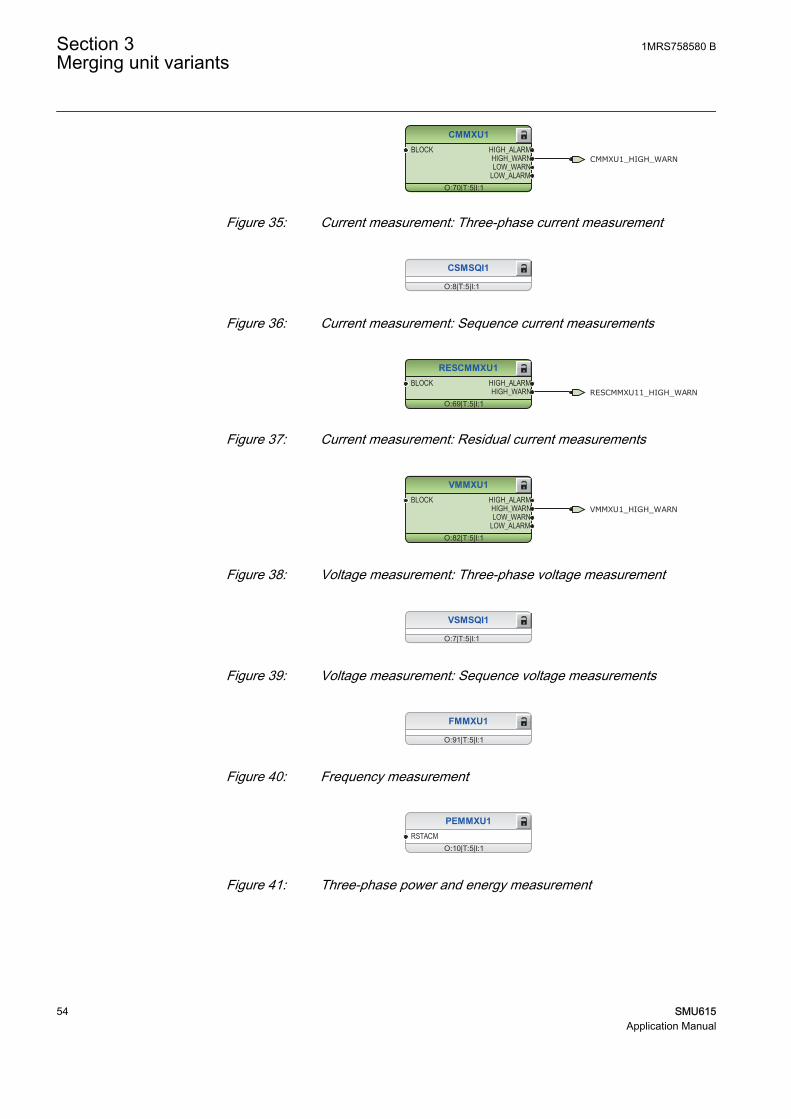
CMMXU1
O:70|T:5|I:1
BLOCK HIGH_ALARMHIGH_WARNLOW_WARN
LOW_ALARM
CMMXU1_HIGH_WARN
GUID-8CC9C621-885B-42E7-BD6F-F63A3EEC536A V1 EN
Figure 35: Current measurement: Three-phase current measurement
CSMSQI1
O:8|T:5|I:1
GUID-489590B6-1D82-4638-B62E-9E4FE4E64D00 V1 EN
Figure 36: Current measurement: Sequence current measurements
RESCMMXU1
O:69|T:5|I:1
BLOCK HIGH_ALARMHIGH_WARN RESCMMXU11_HIGH_WARN
GUID-1D5A1C9B-3497-4B15-A0DC-E29AEA872D06 V1 EN
Figure 37: Current measurement: Residual current measurements
VMMXU1
O:82|T:5|I:1
BLOCK HIGH_ALARMHIGH_WARNLOW_WARN
LOW_ALARM
VMMXU1_HIGH_WARN
GUID-D32678E6-882B-47B3-A24A-3AE2BFD2B81D V1 EN
Figure 38: Voltage measurement: Three-phase voltage measurement
VSMSQI1
O:7|T:5|I:1
GUID-85F8EF14-141C-4137-A814-1D1D1C3613D5 V1 EN
Figure 39: Voltage measurement: Sequence voltage measurements
FMMXU1
O:91|T:5|I:1
GUID-6F7F8590-5123-4CEA-A100-8D821D6054A0 V1 EN
Figure 40: Frequency measurement
PEMMXU1
O:10|T:5|I:1RSTACM
GUID-C30CB240-C2AF-47ED-ADBD-F36B57650619 V1 EN
Figure 41: Three-phase power and energy measurement
Section 3 1MRS758580 BMerging unit variants
54 SMU615Application Manual

3.4.3.7 Functional diagrams for I/O and alarm LEDs
X100-Binary outputs
OR
O:54|T:2.5|I:0
B1B2
O
VMMXU1_HIGH_WARN
CMMXU1_HIGH_WARN
TRPPTRC1_TRIP
TRPPTRC2_TRIP
CBXCBR1_EXE_OP
CBXCBR1_EXE_CL
X100 (PSM)_100.X100-SO1
X100 (PSM)_100.X100-SO2
X100 (PSM)_100.X100-PO4
X100 (PSM)_100.X100-PO1
X100 (PSM)_100.X100-PO3
GUID-E7236770-9845-46FD-AE60-51D2F649CAD7 V1 EN
Figure 42: Binary outputs X100 terminal block
X110-Binary inputs
X110_BI6_CONTROL_OFF
X110_BI2_CB_OPEN
X110_BI1_CB_CLOSED
X110_BI4_CB_TRUCK_OUT/TEST
X110_BI3_CB_TRUCK_IN/SERVICE
X110_BI8_ES_OPEN
X110_BI7_ES_CLOSED
X110_BI5_MCB_OPEN
X110 (BIO-H)_110.X110-Input 1
X110 (BIO-H)_110.X110-Input 2
X110 (BIO-H)_110.X110-Input 3
X110 (BIO-H)_110.X110-Input 4
X110 (BIO-H)_110.X110-Input 5
X110 (BIO-H)_110.X110-Input 6
X110 (BIO-H)_110.X110-Input 7
X110 (BIO-H)_110.X110-Input 8
GUID-4130C1B0-5EEE-4257-B02B-B6FA8FEBA07E V1 EN
Figure 43: Binary inputs X110 terminal block
1MRS758580 B Section 3Merging unit variants
SMU615 55Application Manual

X110-Binary outputs
TRPPTRC3_TRIP
TRPPTRC4_TRIP
TRPPTRC5_TRIP
X110 (BIO-H)_110.X110-HSO1
X110 (BIO-H)_110.X110-HSO2
X110 (BIO-H)_110.X110-HSO3
GUID-E279DB32-9D67-4BCC-B29B-DEEFFFE084B4 V1 EN
Figure 44: Binary outputs X110 terminal block
LED1OKALARMRESET
LED2OKALARMRESET
LED3OKALARMRESET
LED4OKALARMRESET
LED5OKALARMRESET
LED6OKALARMRESET
LED7OKALARMRESET
LED9OKALARMRESET
LED10OKALARMRESET
LED11OKALARMRESET
LED8OKALARMRESET
ORB1B2
O
NOTIN OUT
ORB1B2
O
ANDB1B2
O
ORB1B2
O
ANDB1B2
O
VMMXU1_HIGH_WARN
CMMXU1_HIGH_WARN
X110_BI2_CB_OPEN
X110_BI1_CB_CLOSED
X110_BI4_CB_TRUCK_OUT/TEST
X110_BI3_CB_TRUCK_IN/SERVICE
X110_BI7_ES_CLOSED
GENERAL_TRPPTRC_TRIP
RCHLCCH1_CHLIVRCHLCCH1_REDCHLIV
RDRE1_TRIGGERED
SUPERVISION_ALARM
RESCMMXU11_HIGH_WARN
CB_CONDITION_MONITORINGGNRLLTMS1_EXCLKMSTR
GNRLLTMS1_ALARMGNRLLTMS1_WARNING
GUID-AB8FF91A-D1AE-4E26-AC0F-485453F640AB V1 EN
Figure 45: Default LED connection
Section 3 1MRS758580 BMerging unit variants
56 SMU615Application Manual
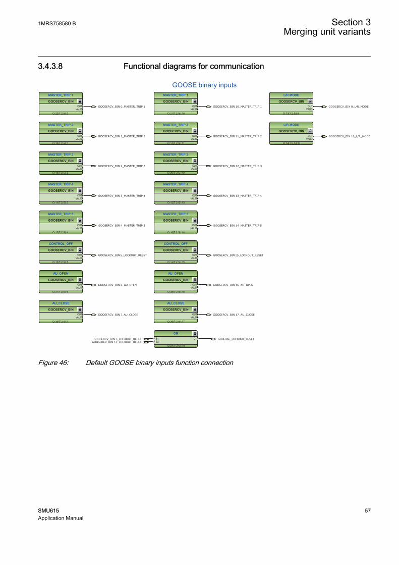
3.4.3.8 Functional diagrams for communication
GOOSERCV_BIN
MASTER_TRIP 1
O:22|T:2.5|I:0
OUTVALID
GOOSERCV_BIN
MASTER_TRIP 2
O:18|T:2.5|I:1
OUTVALID
GOOSERCV_BIN
MASTER_TRIP 3
O:19|T:2.5|I:2
OUTVALID
GOOSERCV_BIN
MASTER_TRIP 4
O:11|T:2.5|I:3
OUTVALID
GOOSERCV_BIN
MASTER_TRIP 5
O:15|T:2.5|I:4
OUTVALID
GOOSERCV_BIN
AU_OPEN
O:37|T:2.5|I:6
OUTVALID
GOOSERCV_BIN
CONTROL_OFF
O:13|T:2.5|I:5
OUTVALID
GOOSERCV_BIN
AU_CLOSE
O:35|T:2.5|I:7
OUTVALID
GOOSERCV_BIN
MASTER_TRIP 1
O:21|T:2.5|I:10
OUTVALID
GOOSERCV_BIN
MASTER_TRIP 2
O:17|T:2.5|I:11
OUTVALID
GOOSERCV_BIN
MASTER_TRIP 3
O:20|T:2.5|I:12
OUTVALID
GOOSERCV_BIN
MASTER_TRIP 4
O:12|T:2.5|I:13
OUTVALID
GOOSERCV_BIN
MASTER_TRIP 5
O:16|T:2.5|I:14
OUTVALID
GOOSERCV_BIN
CONTROL_OFF
O:14|T:2.5|I:15
OUTVALID
GOOSERCV_BIN
AU_OPEN
O:38|T:2.5|I:16
OUTVALID
GOOSERCV_BIN
AU_CLOSE
O:36|T:2.5|I:17
OUTVALID
GOOSERCV_BIN
L/R MODE
O:73|T:2.5|I:8
OUTVALID
GOOSERCV_BIN
L/R MODE
O:74|T:2.5|I:18
OUTVALID
GOOSERCV_BIN 8_L/R_MODE
GOOSERCV_BIN 18_L/R_MODE
GOOSERCV_BIN 5_LOCKOUT_RESET GOOSERCV_BIN 15_LOCKOUT_RESET
GOOSERCV_BIN 6_AU_OPEN GOOSERCV_BIN 16_AU_OPEN
GOOSERCV_BIN 7_AU_CLOSE GOOSERCV_BIN 17_AU_CLOSE
GOOSERCV_BIN 0_MASTER_TRIP 1
GOOSERCV_BIN 1_MASTER_TRIP 2
GOOSERCV_BIN 2_MASTER_TRIP 3
GOOSERCV_BIN 3_MASTER_TRIP 4
GOOSERCV_BIN 4_MASTER_TRIP 5
GOOSERCV_BIN 10_MASTER_TRIP 1
GOOSERCV_BIN 11_MASTER_TRIP 2
GOOSERCV_BIN 12_MASTER_TRIP 3
GOOSERCV_BIN 13_MASTER_TRIP 4
GOOSERCV_BIN 14_MASTER_TRIP 5
GOOSE binary inputs
OR
O:24|T:2.5|I:10
B1B2
OGOOSERCV_BIN 5_LOCKOUT_RESETGOOSERCV_BIN 15_LOCKOUT_RESET
GENERAL_LOCKOUT_RESET
GUID-EDB7A9B6-C0CF-48C6-9D7C-6AD72F8E6A99 V1 EN
Figure 46: Default GOOSE binary inputs function connection
1MRS758580 B Section 3Merging unit variants
SMU615 57Application Manual

GNRLLTMS1ALARM
WARNINGEXCLKMSTR
RCHLCCH1CHLIV_A
REDCHLIV_BLNKLIV_A
REDLNKLIV_B
SMVSENDER
RCHLCCH1_CHLIVRCHLCCH1_REDCHLIV
GNRLLTMS1_ALARMGNRLLTMS1_WARNINGGNRLLTMS1_EXCLKMSTR
Time synchronization
Redundant Ethernet channel supervision
IEC61850-9-2 LE sampled values sending
GUID-1D2AEB7D-92D1-4A42-A5FA-4688711225BF V1 EN
Figure 47: Default communication function connection
Section 3 1MRS758580 BMerging unit variants
58 SMU615Application Manual

Section 4 Merging unit's physical connections
4.1 Inputs
4.1.1 Energizing inputs
4.1.1.1 Phase currents
The merging unit can also be used in single or two-phase applicationsby leaving one or two energizing inputs unoccupied. However, at leastterminals X120:7-8 must be connected.
Table 23: Phase current inputs terminals X120:7-12 with AIM0013
Terminal DescriptionX120:7-8 IL1
X120:9-10 IL2
X120:11-12 IL3
4.1.1.2 Residual current
Table 24: Residual current input terminals X120:13-14 with AIM0013
Terminal DescriptionX120:13-14 Io
Table 25: Residual current input terminals X130:1-2 with SIM0002
Terminal DescriptionX130:1-2 Io
4.1.1.3 Phase voltages
Table 26: Phase voltage inputs terminals X120:1-5 with AIM0013
Terminal DescriptionX120:1-2 U1
X120:3-4 U2
X120:5-6 U3
1MRS758580 B Section 4Merging unit's physical connections
SMU615 59Application Manual

4.1.1.4 Sensor inputs
Table 27: Combi sensor inputs terminals X131-X133 with SIM0002
Terminal DescriptionX131 IL1
U1
X132 IL2U2
X133 IL3U3
4.1.2 Auxiliary supply voltage input
The auxiliary voltage of the merging unit is connected to terminals X100:1-2. At DCsupply, the positive lead is connected to terminal X100:1. The permitted auxiliaryvoltage range (AC/DC or DC) is marked on the top of the LHMI of the merging unit.
Table 28: Auxiliary voltage supply
Terminal DescriptionX100:1 + Input
X100:2 - Input
4.1.3 Binary inputs
The binary inputs can be used, for example, to generate a blocking signal, to unlatchoutput contacts, to trigger the disturbance recorder or for remote control of mergingunit's settings.
Binary inputs of slot X110 are available with configurations C and D.
Table 29: Binary input terminals X110:1-10 with BIO0007 module
Terminal DescriptionX110:1 BI1, +
X110:5 BI1, -
X110:2 BI2, +
X110:5 BI2, -
X110:3 BI3, +
X110:5 BI3, -
X110:4 BI4, +
X110:5 BI4, -
X110:6 BI5, +
X110:10 BI5, -
X110:7 BI6, +
X110:10 BI6, -
Table continues on next page
Section 4 1MRS758580 BMerging unit's physical connections
60 SMU615Application Manual

Terminal DescriptionX110:8 BI7, +
X110:10 BI7, -
X110:9 BI8, +
X110:10 BI8, -
4.1.4 Optional light sensor inputs
If the merging unit is provided with the optional communication module with lightsensor inputs, the pre-manufactured lens-sensor fibers are connected to inputs X13,X14 and X15. See the connection diagrams.For further information, see arcprotection.
The merging unit is provided with connection sockets X13, X14 andX15 only if the optional communication module with light sensorinputs has been installed. If the arc protection option is selected whenordering a merging unit, the light sensor inputs are included in thecommunication module.
Table 30: Light sensor input connectors
Terminal DescriptionX13 Input Light sensor 1
X14 Input Light sensor 2
X15 Input Light sensor 3
4.2 Outputs
4.2.1 Outputs for tripping and controlling
Output contacts PO1, PO2, PO3 and PO4 are heavy-duty trip contacts capable ofcontrolling most circuit breakers. In the factory default configuration, the trip signalsfrom all the protection stages are routed to PO3 and PO4.
Table 31: Output contacts
Terminal DescriptionX100:6 PO1, NO
X100:7 PO1, NO
X100:8 PO2, NO
X100:9 PO2, NO
X100:15 PO3, NO (TCS resistor)
X100:16 PO3, NO
Table continues on next page
1MRS758580 B Section 4Merging unit's physical connections
SMU615 61Application Manual

Terminal DescriptionX100:17 PO3, NO
X100:18 PO3 (TCS1 input), NO
X100:19 PO3 (TCS1 input), NO
X100:20 PO4, NO (TCS resistor)
X100:21 PO4, NO
X100:22 PO4, NO
X100:23 PO4 (TCS2 input), NO
X100:24 PO4 (TCS2 input), NO
4.2.2 Outputs for signalling
SO output contacts can be used for signalling on start and tripping of the merging unit.On delivery from the factory, the start and alarm signals from all the protection stagesare routed to signalling outputs.
Table 32: Output contacts X100:10-14
Terminal DescriptionX100:10 SO1, common
X100:11 SO1, NC
X100:12 SO1, NO
X100:13 SO2, NO
X100:14 SO2, NO
Output contacts of slot X110 are available with application configuration B.
Table 33: Optional high-speed output contacts X110:15-24 with BIO0007
Terminal DescriptionX110:15 HSO1, NO
X110:16 HSO1, NO
X110:19 HSO2, NO
X110:20 HSO2, NO
X110:23 HSO3, NO
X110:24 HSO3, NO
4.2.3 IRF
The IRF contact functions as an output contact for the self-supervision system of themerging unit. Under normal operating conditions, the merging unit is energized andthe contact is closed (X100:3-5). When a fault is detected by the self-supervisionsystem or the auxiliary voltage is disconnected, the contact X100:3-5 drops off and thecontact X100:3-4 closes.
Section 4 1MRS758580 BMerging unit's physical connections
62 SMU615Application Manual

Table 34: IRF contact
Terminal DescriptionX100:3 IRF, common
X100:4 Closed; IRF, or Uaux disconnected
X100:5 Closed; no IRF, and Uaux connected
1MRS758580 B Section 4Merging unit's physical connections
SMU615 63Application Manual

64

Section 5 Glossary
AI Analog inputBCU Breaker control unitBI/O Binary input/outputBO Binary outputCB Circuit breakerDAN Doubly attached nodeDC 1. Direct current
2. Disconnector3. Double command
DPC Double-point controlEMC Electromagnetic compatibilityEthernet A standard for connecting a family of frame-based
computer networking technologies into a LANFIFO First in, first outFTP File transfer protocolFTPS FTP SecureGOOSE Generic Object-Oriented Substation EventHSR High-availability seamless redundancyHTTPS Hypertext Transfer Protocol SecureI/O Input/outputIEC International Electrotechnical CommissionIEC 61850 International standard for substation communication and
modelingIEC 61850-8-1 A communication protocol based on the IEC 61850
standard seriesIEC 61850-9-2 A communication protocol based on the IEC 61850
standard seriesIEC 61850-9-2 LE Lite Edition of IEC 61850-9-2 offering process bus
interfaceIED Intelligent electronic deviceIEEE 1686 Standard for Substation Intelligent Electronic Devices'
(IEDs') Cyber Security Capabilities
1MRS758580 B Section 5Glossary
SMU615 65Application Manual

IP address A set of four numbers between 0 and 255, separated byperiods. Each server connected to the Internet isassigned a unique IP address that specifies the locationfor the TCP/IP protocol.
LAN Local area networkLE Light EditionLED Light-emitting diodeLHMI Local human-machine interfaceMCB Miniature circuit breakerMMS 1. Manufacturing message specification
2. Metering management systemMV Medium voltageNC Normally closedNO Normally openPCM600 Protection and Control IED ManagerPO Power outputPRP Parallel redundancy protocolPTP Precision Time ProtocolRIO600 Remote I/O unitRJ-45 Galvanic connector typeSAN Single attached nodeSMU615 Substation merging unitSMV Sampled measured valuesSO Signal outputTCS Trip-circuit supervisionWAN Wide area networkWHMI Web human-machine interface
Section 5 1MRS758580 BGlossary
66 SMU615Application Manual

67


ABB Distribution SolutionsDistribution AutomationP.O. Box 699FI-65101 VAASA, FinlandPhone +358 10 22 11
www.abb.com/mediumvoltagewww.abb.com/substationautomation
—
© Copyright 2019 ABB. All rights reserved. 1MR
S75
8580
B