Embed Size (px)
Citation preview
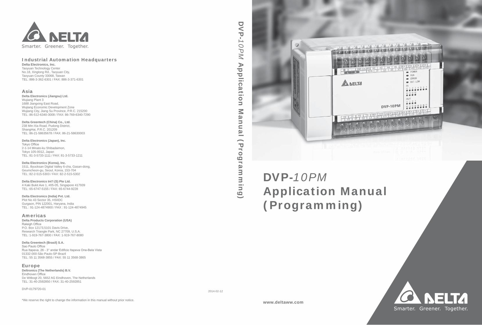
www.deltaww.com
DVP-10PM Application Manual (Programming)
2014-02-12
Industrial Automation HeadquartersDelta Electronics, Inc. Taoyuan Technology CenterNo.18, Xinglong Rd., Taoyuan City, Taoyuan County 33068, TaiwanTEL: 886-3-362-6301 / FAX: 886-3-371-6301
AsiaDelta Electronics (Jiangsu) Ltd.Wujiang Plant 31688 Jiangxing East Road, Wujiang Economic Development ZoneWujiang City, Jiang Su Province, P.R.C. 215200TEL: 86-512-6340-3008 / FAX: 86-769-6340-7290
Delta Greentech (China) Co., Ltd.238 Min-Xia Road, Pudong District, ShangHai, P.R.C. 201209TEL: 86-21-58635678 / FAX: 86-21-58630003 Delta Electronics (Japan), Inc.Tokyo Office 2-1-14 Minato-ku Shibadaimon, Tokyo 105-0012, JapanTEL: 81-3-5733-1111 / FAX: 81-3-5733-1211
Delta Electronics (Korea), Inc.1511, Byucksan Digital Valley 6-cha, Gasan-dong, Geumcheon-gu, Seoul, Korea, 153-704TEL: 82-2-515-5303 / FAX: 82-2-515-5302
Delta Electronics Int’l (S) Pte Ltd.4 Kaki Bukit Ave 1, #05-05, Singapore 417939TEL: 65-6747-5155 / FAX: 65-6744-9228
Delta Electronics (India) Pvt. Ltd.Plot No 43 Sector 35, HSIIDC Gurgaon, PIN 122001, Haryana, India TEL : 91-124-4874900 / FAX : 91-124-4874945
AmericasDelta Products Corporation (USA)Raleigh OfficeP.O. Box 12173,5101 Davis Drive, Research Triangle Park, NC 27709, U.S.A.TEL: 1-919-767-3800 / FAX: 1-919-767-8080
Delta Greentech (Brasil) S.A.Sao Paulo OfficeRua Itapeva, 26 - 3° andar Edificio Itapeva One-Bela Vista01332-000-São Paulo-SP-BrazilTEL: 55 11 3568-3855 / FAX: 55 11 3568-3865
EuropeDeltronics (The Netherlands) B.V.Eindhoven OfficeDe Witbogt 20, 5652 AG Eindhoven, The Netherlands TEL: 31-40-2592850 / FAX: 31-40-2592851
DVP-0179720-01
*We reserve the right to change the information in this manual without prior notice.
DV
P-1
0P
M A
pp
licatio
n M
an
ual (P
rog
ram
min
g)
i
DVP-10PM Application Manual
Contents Chapter 1 Program Framework of a DVP-PM Series Motion Controller 1.1 Structure of O100 ................................................................................................1-1
1.1.1 Manual Function of O100 .............................................................................1-2 1.2 Structure of Ox Motion Subroutines.....................................................................1-3 1.3 Structure of P Subroutines...................................................................................1-4 1.4 Using O100, Ox Motion Subroutines, and P Subroutines....................................1-6
1.4.1 Structure of a Program .................................................................................1-6 Chapter 2 Hardware Specifications and Wiring 2.1 Hardware Specifications......................................................................................2-1
2.1.1 Specifications for Power ...............................................................................2-1 2.1.2 Electrical Specifications for Input Terminals/Output Terminals......................2-1 2.1.3 Dimensions...................................................................................................2-4
2.2 Wiring ..................................................................................................................2-5 2.2.1 Installation of a DVP-10PM Series Motion Controller in a Control Box.........2-6 2.2.2 Wiring Power Input .......................................................................................2-6 2.2.3 Safety Wiring ................................................................................................2-7 2.2.4 Wiring Input/Output Terminals ......................................................................2-7 2.2.5 Wiring a DVP-10PM Series Motion Controller and an Inferior Servo Drive 2-14
2.3 Communication Ports ........................................................................................2-24 2.3.1 COM1 (RS-232 Port)..................................................................................2-24 2.3.2 COM2 (RS-485 Port)..................................................................................2-25 2.3.3 COM3 (RS-232/RS-485 Port).....................................................................2-25
Chapter 3 Devices 3.1 Device Lists .........................................................................................................3-1 3.2 Values, Constants, and Floating-point Numbers .................................................3-4 3.3 External Input Devices and External Output Devices ..........................................3-6 3.4 Auxiliary Relays ...................................................................................................3-8 3.5 Stepping Relays ..................................................................................................3-8 3.6 Timers .................................................................................................................3-8 3.7 Counters..............................................................................................................3-9 3.8 Registers ...........................................................................................................3-14
3.8.1 Data Registers............................................................................................3-15 3.8.2 Index Registers ..........................................................................................3-15
3.9 Pointers .............................................................................................................3-16
i i
3.10 Specail Auxiliary Relays and Special Data Registers ........................................3-16 3.11 Functions of Special Auxiliary Relays and Special Data Registers ...................3-30 3.12 Special Data Registers for Motion Axes ............................................................3-44
3.12.1 Descriptions of the Special Data Registers Related to Motion....................3-47 3.12.2 Introduction of Modes of Motion .................................................................3-68 3.12.3 Special Data Registers for Motion Axes .....................................................3-69
Chapter 4 Basic Instructions 4.1 Table of Basic Instructions ..................................................................................4-1 4.2 Descriptions of the Basic Instructions..................................................................4-3 Chapter 5 Applied Instructions and Basic Usage 5.1 Table of Applied Instructions ...............................................................................5-1 5.2 Structure of an Applied Instruction.......................................................................5-4 5.3 Processing Values ...............................................................................................5-7 5.4 Using Index Registers to Modify Operands .........................................................5-9 5.5 Instruction Index ................................................................................................5-10 5.6 Descriptions of the Applied Instructions.............................................................5-13
(API 00~09) Loop control.............................................................................5-13 (API 10~19) Transfer and comparison.........................................................5-22
(API 20~29) Arithmetic.................................................................................5-35 (API 30~39) Rotation and move ..................................................................5-47 (API 40~49) Data processing ......................................................................5-58 (API 50) High-speed processing..................................................................5-72 (API 61~69) Convenience ...........................................................................5-73 (API 78~87) I/O ...........................................................................................5-80 (API 100~101) Communication ...................................................................5-85 (API 110~175) Floating-point value .............................................................5-94 (API 215~223) Logical operation ............................................................... 5-125 (API 224~246) Comparison instructions .................................................... 5-128 (API 147, 154, 202, 203, 256~260) Other instructions .............................. 5-131
5.7 Motion Control Function Block Table ...............................................................5-144 5.8 Introduction of the Pins in a Motion Control Function Block ............................5-145
5.8.1 Definitions of Input Pins/Output Pins ........................................................5-145 5.8.2 Timing Diagram for Input/Output Pins ......................................................5-147 5.8.3 Introducing the Use of PMSoft..................................................................5-148
5.9 Delta-defined Parameter Table ........................................................................5-150 5.10 Uniaxial Motion Control Function Blocks .........................................................5-152
5.10.1 Absolute Single-speed Motion..................................................................5-152 5.10.2 Relative Single-speed Motion...................................................................5-156
i i i
5.10.3 Absolute Two-speed Motion .....................................................................5-160 5.10.4 Relative Two-speed Motion ......................................................................5-163 5.10.5 Inserting Single-speed Motion ..................................................................5-166 5.10.6 Inserting Two-speed Motion .....................................................................5-170 5.10.7 JOG Motion ..............................................................................................5-173 5.10.8 Manual Pulse Generator Mode.................................................................5-176 5.10.9 Electronic Gear Motion.............................................................................5-179 5.10.10 Returning Home .......................................................................................5-181 5.10.11 Stopping Uniaxial Motion..........................................................................5-183 5.10.12 Parameter Setting I ..................................................................................5-186 5.10.13 Parameter Setting II .................................................................................5-187 5.10.14 Reading the Present Position/Speed of an Axis .......................................5-189 5.10.15 State of an Axis.........................................................................................5-191 5.10.16 Setting the Present Position of an Axis.....................................................5-193 5.10.17 Setting the Polarities of Input Terminals ...................................................5-194
5.11 Multiaxial Motion Control Function Blocks .......................................................5-196 5.11.1 Multiaxial Absolute Linear Interpolation ....................................................5-196 5.11.2 Multiaxial Relative Linear Interpolation.....................................................5-197 5.11.3 Stopping Multiaxial Linear Interpolation....................................................5-200
5.12 Other Motion Control Function Blocks .............................................................5-203 5.12.1 High-speed Counter .................................................................................5-203 5.12.2 High-speed Timer .....................................................................................5-206 5.12.3 Setting High-speed Comparison...............................................................5-209 5.12.4 Resetting High-speed Comparison........................................................... 5-211 5.12.5 Setting High-speed Capture .....................................................................5-215 5.12.6 High-speed Masking.................................................................................5-218 5.12.7 Setting an Interrupt...................................................................................5-220
Chapter 6 Multiaxial Interpolation
6.1 Introduction of Multiaxial Interpolation .................................................................6-1 6.2 Description of TO.................................................................................................6-1 Chapter 7 CANopen Communication Card 7.1 Introduction of DVP-FPMC: CANopen Communication Card ..............................7-1 7.2 Specifications ......................................................................................................7-1 7.3 Product Profile and Installation ............................................................................7-2 7.4 Parameters for Control Registers ........................................................................7-2 7.5 Descriptions of Control Registers ........................................................................7-4 7.6 Setting a DVP-FPMC Mode...............................................................................7-19 7.7 Ethernet Mode of DVP-FPMC ...........................................................................7-21
i v
7.7.1 Communication between DVP-FPMC and an HMI.....................................7-22 7.7.2 Communication between DVP-FPMC and PMSoft.....................................7-24
7.8 LED Indicators and Troubleshooting .................................................................7-27 Chapter 8 High-speed Capture and High-speed Comparison
8.1 High-speed Comparison and High-speed Capture ..............................................8-1 8.2 High-speed Comparison......................................................................................8-3 8.3 High-speed Capture ............................................................................................8-6
Chapter 9 Appendix 9.1 Appendix A: Error Code Table.............................................................................9-1

v
1 Program Framework of a DVP-PM Series Motion Controller
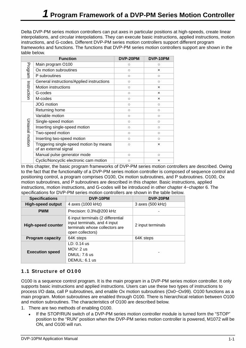
Delta DVP-PM series motion controllers can put axes in particular positions at high-speeds, create linear interpolations, and circular interpolations. They can execute basic instructions, applied instructions, motion instructions, and G-codes. Different DVP-PM series motion controllers support different program frameworks and functions. The functions that DVP-PM series motion controllers support are shown in the table below.
Function DVP-20PM DVP-10PM Main program O100 Ox motion subroutines ×
Program
P subroutines General instructions/Applied instructions Motion instructions × G-codes ×
Instruction M-codes × JOG motion Returning home Variable motion Single-speed motion Inserting single-speed motion Two-speed motion Inserting two-speed motion Triggering single-speed motion by means of an external signal
×
Manual pulse generator mode
Uniaxial m
otion
Cyclic/Noncyclic electronic cam motion × In this chapter, the basic program frameworks of DVP-PM series motion controllers are described. Owing to the fact that the functionality of a DVP-PM series motion controller is composed of sequence control and positioning control, a program comprises O100, Ox motion subroutines, and P subroutines. O100, Ox motion subroutines, and P subroutines are described in this chapter. Basic instructions, applied instructions, motion instructions, and G-codes will be introduced in other chapter 4~chapter 6. The specifications for DVP-PM series motion controllers are shown in the table below.
Specifications DVP-10PM DVP-20PM High-speed output 4 axes (1000 kHz) 3 axes (500 kHz)
PWM Precision: 0.3%@200 kHz -
High-speed counter 6 input terminals (2 differential input terminals, and 4 input terminals whose collectors are open collectors)
2 input terminals
Program capacity 64K steps 64K steps
Execution speed
LD: 0.14 us MOV: 2 us DMUL: 7.6 us DEMUL: 6.1 us
-
1.1 Structure of O100
O100 is a sequence control program. It is the main program in a DVP-PM series motion controller. It only supports basic instructions and applied instructions. Users can use these two types of instructions to process I/O data, call P subroutines, and enable Ox motion subroutines (Ox0~Ox99). O100 functions as a main program. Motion subroutines are enabled through O100. There is hierarchical relation between O100 and motion subroutines. The characteristics of O100 are described below. 1. There are two methods of enabling O100.
If the STOP/RUN switch of a DVP-PM series motion controller module is turned form the “STOP” position to the “RUN” position when the DVP-PM series motion controller is powered, M1072 will be ON, and O100 will run.
DVP-10PM Application Manual 1-1
1 Program Framework of a DVP-PM Series Motion Controller
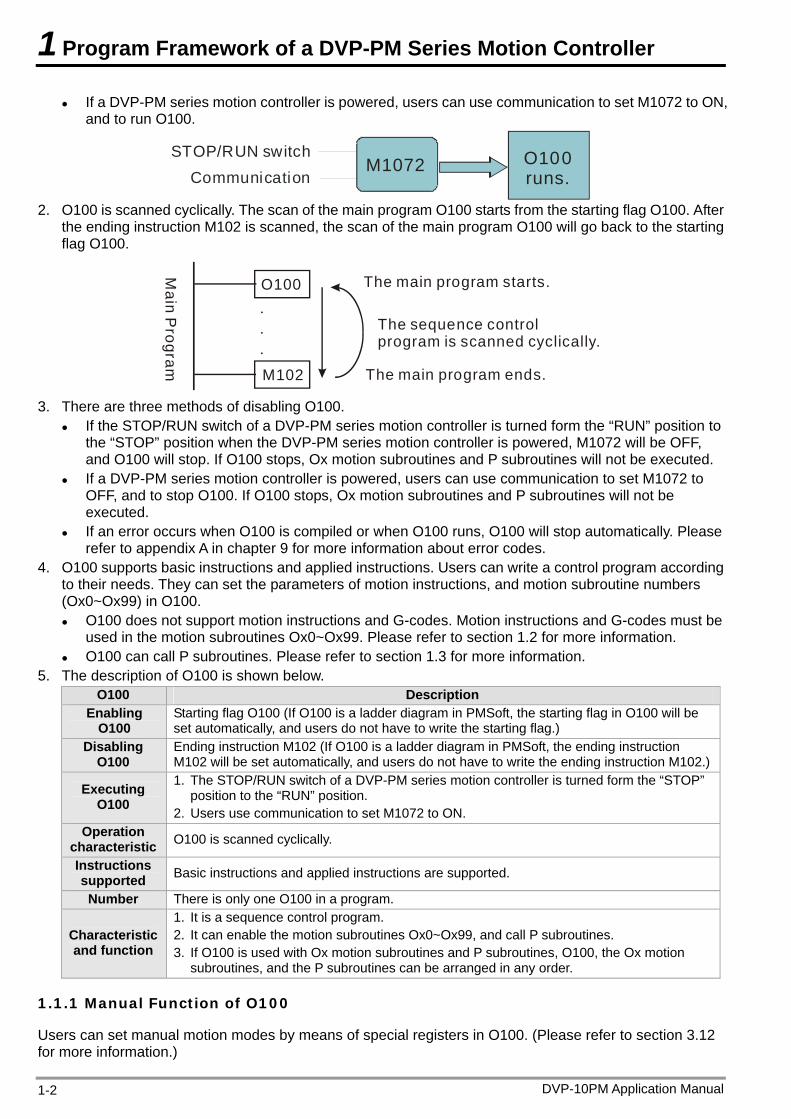
If a DVP-PM series motion controller is powered, users can use communication to set M1072 to ON, and to run O100.
CommunicationSTOP/RUN switch
M1072 O100runs.
2. O100 is scanned cyclically. The scan of the main program O100 starts from the starting flag O100. After
the ending instruction M102 is scanned, the scan of the main program O100 will go back to the starting flag O100.
O100
M102
.
.
.
The main program starts.
The main program ends.
The sequence control program is scanned cyclically.
Main P
rogram
3. There are three methods of disabling O100.
If the STOP/RUN switch of a DVP-PM series motion controller is turned form the “RUN” position to the “STOP” position when the DVP-PM series motion controller is powered, M1072 will be OFF, and O100 will stop. If O100 stops, Ox motion subroutines and P subroutines will not be executed.
If a DVP-PM series motion controller is powered, users can use communication to set M1072 to OFF, and to stop O100. If O100 stops, Ox motion subroutines and P subroutines will not be executed.
If an error occurs when O100 is compiled or when O100 runs, O100 will stop automatically. Please refer to appendix A in chapter 9 for more information about error codes.
4. O100 supports basic instructions and applied instructions. Users can write a control program according to their needs. They can set the parameters of motion instructions, and motion subroutine numbers (Ox0~Ox99) in O100. O100 does not support motion instructions and G-codes. Motion instructions and G-codes must be
used in the motion subroutines Ox0~Ox99. Please refer to section 1.2 for more information. O100 can call P subroutines. Please refer to section 1.3 for more information.
5. The description of O100 is shown below. O100 Description
Enabling O100
Starting flag O100 (If O100 is a ladder diagram in PMSoft, the starting flag in O100 will be set automatically, and users do not have to write the starting flag.)
Disabling O100
Ending instruction M102 (If O100 is a ladder diagram in PMSoft, the ending instruction M102 will be set automatically, and users do not have to write the ending instruction M102.)
Executing O100
1. The STOP/RUN switch of a DVP-PM series motion controller is turned form the “STOP” position to the “RUN” position.
2. Users use communication to set M1072 to ON. Operation
characteristic O100 is scanned cyclically.
Instructions supported Basic instructions and applied instructions are supported.
Number There is only one O100 in a program.
Characteristic and function
1. It is a sequence control program. 2. It can enable the motion subroutines Ox0~Ox99, and call P subroutines. 3. If O100 is used with Ox motion subroutines and P subroutines, O100, the Ox motion
subroutines, and the P subroutines can be arranged in any order.
1.1.1 Manual Function of O100
Users can set manual motion modes by means of special registers in O100. (Please refer to section 3.12 for more information.)
DVP-10PM Application Manual 1-2
1 Program Framework of a DVP-PM Series Motion Controller
1.2 Structure of Ox Motion Subroutines
The motion subroutines Ox0~Ox99 are motion control programs. They are subroutines which control the motion of the axes of a DVP-PM series motion controller. Ox0~Ox99 support basic instructions, applied instructions, motion instructions, and G-codes. They can call P subroutines. Users can control the paths of the axes of a DVP-PM series motion controller through Ox motion subroutines. The characteristics of Ox motion subroutines are described below. 1. There are two methods of enabling an Ox motion subroutine.
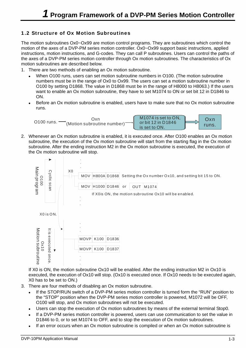
When O100 runs, users can set motion subroutine numbers in O100. (The motion subroutine numbers must be in the range of Ox0 to Ox99. The users can set a motion subroutine number in O100 by setting D1868. The value in D1868 must be in the range of H8000 to H8063.) If the users want to enable an Ox motion subroutine, they have to set M1074 to ON or set bit 12 in D1846 to ON.
Before an Ox motion subroutine is enabled, users have to make sure that no Ox motion subroutine runs.
Oxn (Motion subroutine number)O100 runs.
M1074 is set to ON, or bit 12 in D1846is set to ON.
Oxnruns.
2. Whenever an Ox motion subroutine is enabled, it is executed once. After O100 enables an Ox motion subroutine, the execution of the Ox motion subroutine will start from the starting flag in the Ox motion subroutine. After the ending instruction M2 in the Ox motion subroutine is executed, the execution of the Ox motion subroutine will stop.
MOV
.
.
.
.
.
.
.
.
.
H800A D1868
OUT M1074
X0
.
.
.
MOVP K100 D1836
MOVP K100 D1837
MOV H1000 D1846 or
Setting the Ox number O x10, and setting b it 15 to ON.
If X0is ON, the motion subroutine Ox10 wi ll be enabled.C
yclic scanIt is e
xecuted on
ce.
X0 is O N.
Ox1
0M
otion subroutineO
100
Main program
If X0 is ON, the motion subroutine Ox10 will be enabled. After the ending instruction M2 in Ox10 is executed, the execution of Ox10 will stop. (Ox10 is executed once. If Ox10 needs to be executed again, X0 has to be set to ON.)
3. There are four methods of disabling an Ox motion subroutine. If the STOP/RUN switch of a DVP-PM series motion controller is turned form the “RUN” position to
the “STOP” position when the DVP-PM series motion controller is powered, M1072 will be OFF, O100 will stop, and Ox motion subroutines will not be executed.
Users can stop the execution of Ox motion subroutines by means of the external terminal Stop0.
If a DVP-PM series motion controller is powered, users can use communication to set the value in D1846 to 0, or to set M1074 to OFF, and to stop the execution of Ox motion subroutines.
If an error occurs when an Ox motion subroutine is compiled or when an Ox motion subroutine is
DVP-10PM Application Manual 1-3
1 Program Framework of a DVP-PM Series Motion Controller
executed, the execution of the Ox motion subroutine will stop automatically. Please refer to appendix A in chapter 9 for more information about error codes.
4. An Ox motion subroutine supports basic instructions, applied instructions, motion instructions, and G-codes. Users can write a motion program according to their needs. They can control the motion of the axes of a DVP-PM series motion controller by setting the parameters of the axes. Basic instructions, applied instructions, motion instructions and G-codes must be used in the
motion subroutines Ox0~Ox99. Ox motion subroutines can call P subroutines. Please refer to section 1.3 for more information.
5. The description of Ox motion subroutines is shown below. Ox motion subroutine Description
Enabling an Ox motion subroutine
There are 100 Ox motion subroutines (Ox0~Ox99). (If an Ox motion subroutine is a ladder diagram in PMSoft, the starting flag in the Ox motion subroutine will be set automatically, and users do not have to write the starting flag.)
Disabling an Ox motion subroutine
Ending instruction M2 (If an Ox motion subroutine is a ladder diagram in PMSoft, the ending instruction M2 will be set automatically, and users do not have to write the ending instruction M2.)
Executing an Ox motion subroutine
1. If users set bit 12 in D1846 or M1074 to ON when O100 runs, an Ox motion subroutine will be enabled.
2. If users use communication to set bit 12 in D1846 or M1074 to ON when O100 runs, an Ox motion subroutine will be enabled.
3. Users can stop the execution of Ox motion subroutines by means of the external terminal Stop0.
Note: Before an Ox motion subroutine is enabled, users have to make sure that no Ox motion subroutine runs.
Operation characteristic
Whenever an Ox motion subroutine is enabled, it is executed once. If an Ox motion subroutine needs to be executed again, it has to be enabled again.
Instructions supported
Basic instructions, applied instructions, motion instructions, and G-codes are supported. Note: Users have to avoid using pulse instructions.
Number There are 100 Ox motion subroutines in a program. If users want to enable a motion subroutine number, they have to set D1868, and set bit 12 in D1846 or M1074 to ON.
Characteristic and function
1. Ox0~Ox99 are motion subroutines. (They can only be enabled by O100.) 2. An Ox motion subroutine can be enabled/disabled by an external terminal, a program, or
communication. 3. Ox motion subroutines can call P subroutines. 4. If Ox motion subroutines are used with O100 and P subroutines, the Ox motion
subroutines, O100, and the P subroutines can be arranged in any order.
1.3 Structure of P Subroutines
P subroutines are general subroutines. They can be called by O100 and Ox motion subroutines. If P subroutines are called by O100, the P subroutines will support basic instructions and applied instructions. If P subroutines are called by Ox0~Ox99, the P subroutines will support basic instructions, applied instructions, motion instructions, and G-codes. After O100 or an Ox motion subroutine calls a P subroutine, the P subroutine will be executed. After SRET in the P subroutine is executed, the lines under the instruction which calls the P subroutine will be executed. 1. There are two methods of enabling a P subroutine.
O100 can call P subroutines. Ox motion subroutines can call P subroutines.
2. Whenever a P subroutine is called, it is executed once. After O100 or an Ox motion subroutine calls a P subroutine, the P subroutine will be executed. After the ending instruction SRET in the P subroutine is executed, the execution of the P subroutine will stop, and the lines under the instruction which calls the P subroutine will be executed.
DVP-10PM Application Manual 1-4
1 Program Framework of a DVP-PM Series Motion Controller
MOV
CALL
.
.
.
.
.
.
H800A D1868
OUT M1074
X0
.
.
.
.
.
P0
P2
CALL
b
a
M1000
M1000
Sub
rou
tine
sect
ion
MOV P K100 D1836
ABST
DRV X-20000 Y20000
MOV P D1837K100
.
.
.
.
O100
Main p
rogram
Cyclic scan
O100 and Ox10 diverge. Calling P0
Setting the motion subroutine number Ox10
If X0 is ON, Ox10 will be enabled.The path a is valid.
Ox10 is execute
d once.
OX
10M
otion subroutine
Ox10 is e
xecuted once.
Ca lling P2
P2
subroutine
P2 is execute
d once.
P2 is executed once
.
P0
subroutine
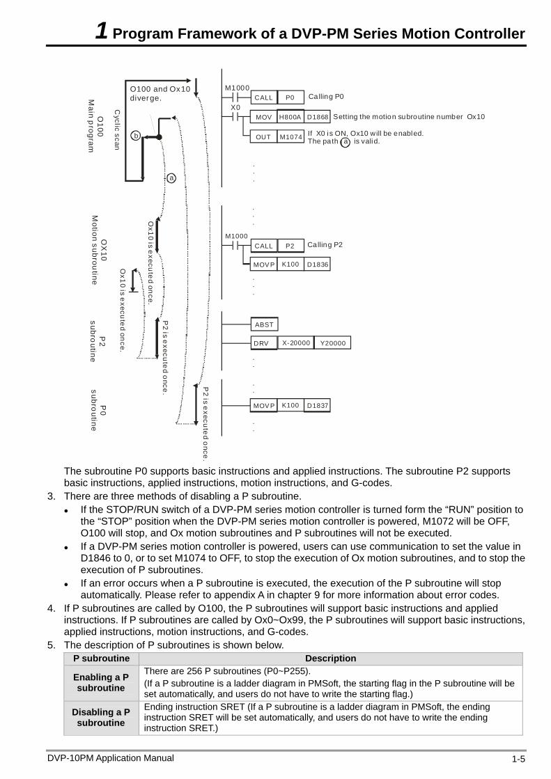
The subroutine P0 supports basic instructions and applied instructions. The subroutine P2 supports basic instructions, applied instructions, motion instructions, and G-codes.
3. There are three methods of disabling a P subroutine. If the STOP/RUN switch of a DVP-PM series motion controller is turned form the “RUN” position to
the “STOP” position when the DVP-PM series motion controller is powered, M1072 will be OFF, O100 will stop, and Ox motion subroutines and P subroutines will not be executed.
If a DVP-PM series motion controller is powered, users can use communication to set the value in D1846 to 0, or to set M1074 to OFF, to stop the execution of Ox motion subroutines, and to stop the execution of P subroutines.
If an error occurs when a P subroutine is executed, the execution of the P subroutine will stop automatically. Please refer to appendix A in chapter 9 for more information about error codes.
4. If P subroutines are called by O100, the P subroutines will support basic instructions and applied instructions. If P subroutines are called by Ox0~Ox99, the P subroutines will support basic instructions, applied instructions, motion instructions, and G-codes.
5. The description of P subroutines is shown below. P subroutine Description
Enabling a P subroutine
There are 256 P subroutines (P0~P255). (If a P subroutine is a ladder diagram in PMSoft, the starting flag in the P subroutine will be set automatically, and users do not have to write the starting flag.)
Disabling a P subroutine
Ending instruction SRET (If a P subroutine is a ladder diagram in PMSoft, the ending instruction SRET will be set automatically, and users do not have to write the ending instruction SRET.)
DVP-10PM Application Manual 1-5
1 Program Framework of a DVP-PM Series Motion Controller
DVP-10PM Application Manual 1-6
P subroutine Description
Executing a P subroutine
1. O100 can call P subroutines. 2. Ox motion subroutines can call P subroutines.
Operation characteristic
Whenever a P subroutine is enabled, it is executed once. If a Pn subroutine needs to be executed again, it has to be enabled again.
Instruction supported
1. If P subroutines are called by O100, the P subroutines will support basic instructions and applied instructions.
2. If P subroutines are called by Ox motion subroutines, the P subroutines will support basic instructions, applied instructions, motion instructions, and G-codes.
Note: If P subroutines are called by Ox motion subroutines, users have to avoid using pulse instructions.
Number There are 256 P subroutines in a program.
Characteristic and function
1. P subroutines are general subroutines. 2. P subroutines can be called by O100 and Ox motion subroutines. 3. If P subroutines are used with O100 and Ox motion subroutines, the P subroutines,
O100, and the Ox motion subroutines can be arranged in any order.
1.4 Using O100, Ox Motion Subroutines, and P Subroutines
O100, Ox motion subroutines, and P subroutines are introduced in section 1.1~section 1.3. In this section, a program composed of O100, Ox motion subroutines, and P subroutines is described.
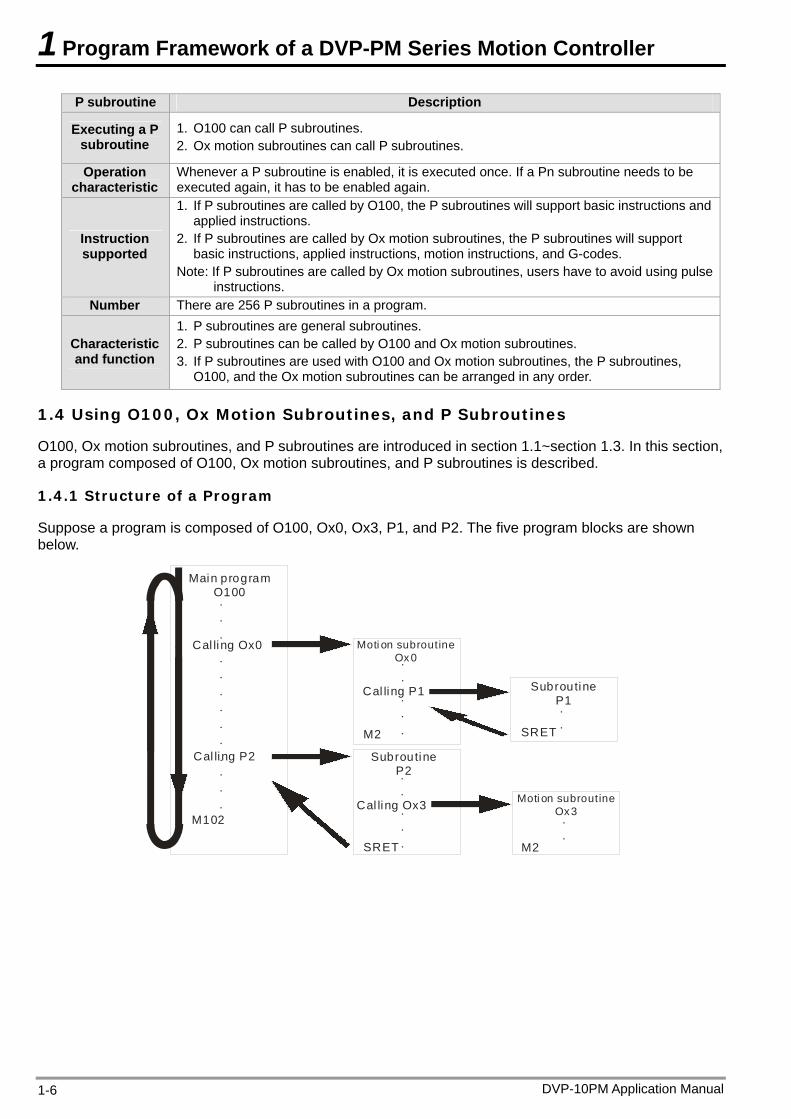
1.4.1 Structure of a Program
Suppose a program is composed of O100, Ox0, Ox3, P1, and P2. The five program blocks are shown below.
Main program O100
M102
...
..........
Cal ling Ox0
Cal ling P2
Moti on subroutineOx 0
Cal ling P1
..
...M2
Subroutine P2
Cal ling Ox3
..
...SRET
Moti on subroutineOx3..
M2
Subroutine P1..SRET
1 Program Framework of a DVP-PM Series Motion Controller
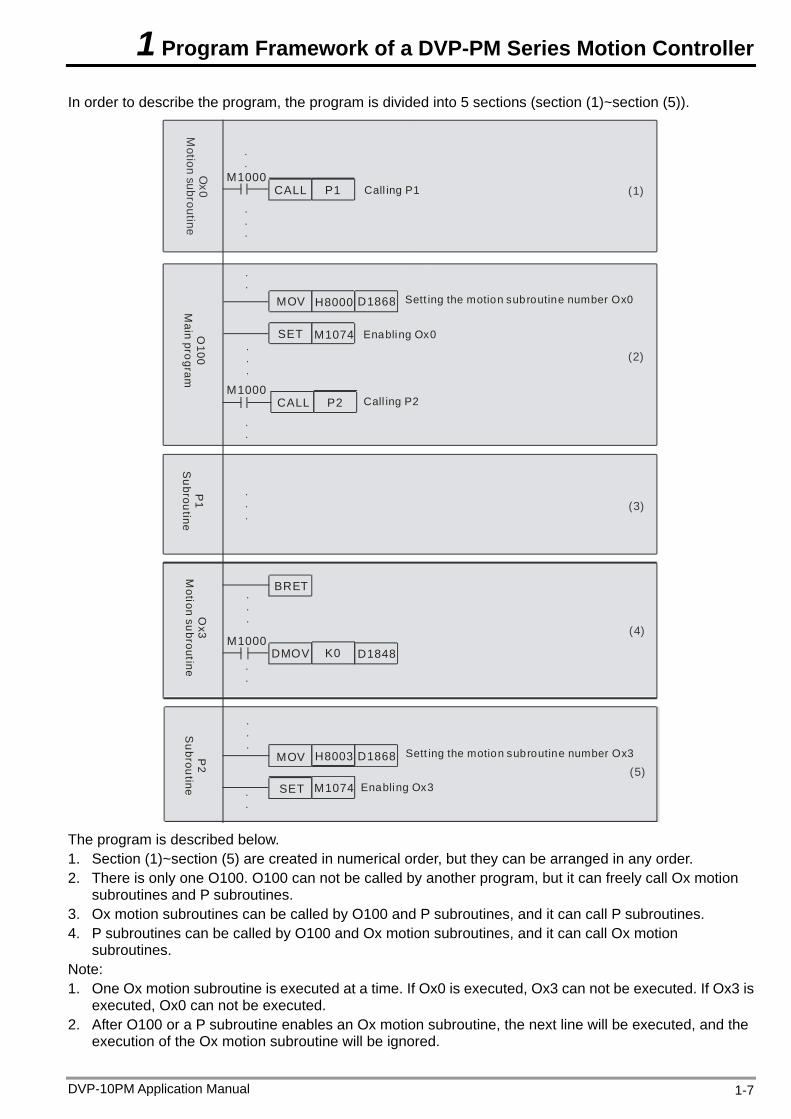
In order to describe the program, the program is divided into 5 sections (section (1)~section (5)).
.
.
.
.
.
.
.
.
(1)
(3)
(2)
(5)
.
.
.
.
.
.
.
.(4)
.
.
.
.
.
.
.
M1000CALL P1
MOV H8000 D1868
SET M1074
CALL P2M1000
BRET
DMOV
MOV H8003 D1868
M1074SET
K0 D1848M1000
.
.
Ox0
Motion subroutine
Call ing P1
O100
Main program
Sett ing the motion subroutine number Ox0
Enabling Ox0
Call ing P2
P1
Subroutine
Ox3
Motion subroutine
P2
Subroutine
Sett ing the motion subroutine number Ox3
Enabling Ox3
The program is described below. 1. Section (1)~section (5) are created in numerical order, but they can be arranged in any order. 2. There is only one O100. O100 can not be called by another program, but it can freely call Ox motion
subroutines and P subroutines. 3. Ox motion subroutines can be called by O100 and P subroutines, and it can call P subroutines. 4. P subroutines can be called by O100 and Ox motion subroutines, and it can call Ox motion
subroutines. Note: 1. One Ox motion subroutine is executed at a time. If Ox0 is executed, Ox3 can not be executed. If Ox3 is
executed, Ox0 can not be executed. 2. After O100 or a P subroutine enables an Ox motion subroutine, the next line will be executed, and the
execution of the Ox motion subroutine will be ignored.
DVP-10PM Application Manual 1-7
1 Program Framework of a DVP-PM Series Motion Controller
DVP-10PM Application Manual 1-8
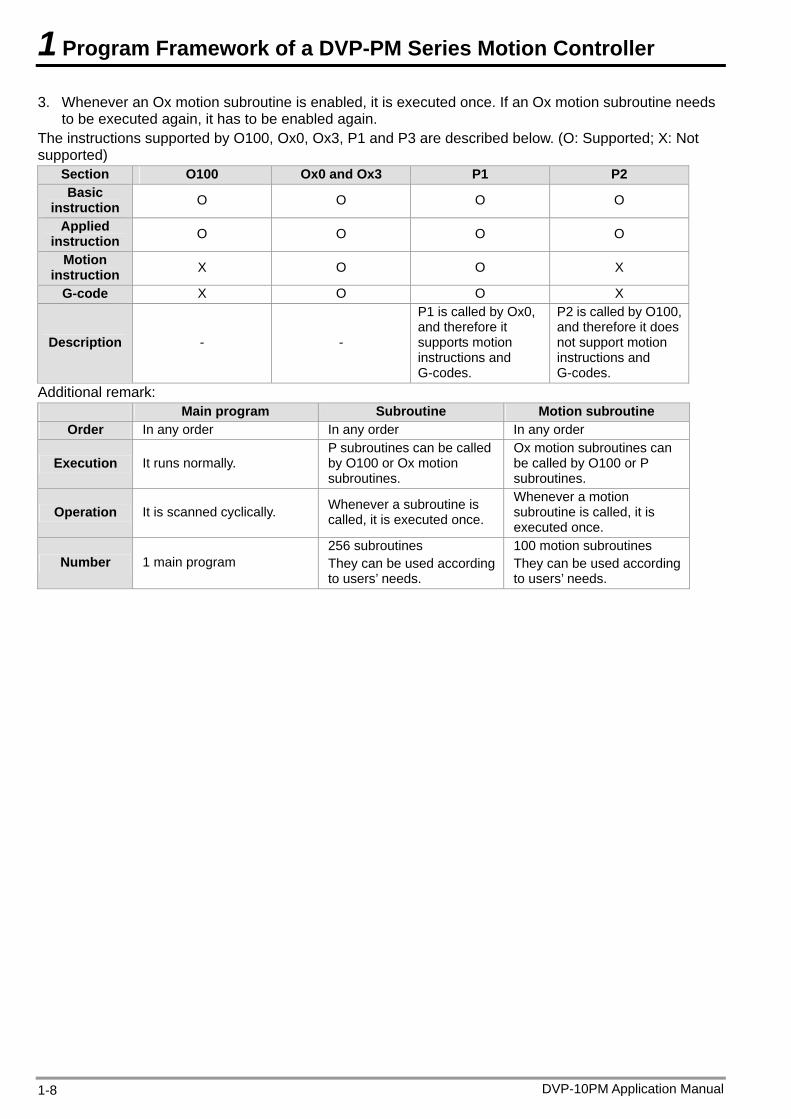
3. Whenever an Ox motion subroutine is enabled, it is executed once. If an Ox motion subroutine needs to be executed again, it has to be enabled again.
The instructions supported by O100, Ox0, Ox3, P1 and P3 are described below. (O: Supported; X: Not supported)
Section O100 Ox0 and Ox3 P1 P2 Basic
instruction O O O O
Applied instruction O O O O
Motion instruction X O O X
G-code X O O X
Description - -
P1 is called by Ox0, and therefore it supports motion instructions and G-codes.
P2 is called by O100, and therefore it does not support motion instructions and G-codes.
Additional remark: Main program Subroutine Motion subroutine
Order In any order In any order In any order
Execution It runs normally. P subroutines can be called by O100 or Ox motion subroutines.
Ox motion subroutines can be called by O100 or P subroutines.
Operation It is scanned cyclically. Whenever a subroutine is called, it is executed once.
Whenever a motion subroutine is called, it is executed once.
Number 1 main program 256 subroutines They can be used according to users’ needs.
100 motion subroutines They can be used according to users’ needs.
2 Hardware Specifications and Wiring
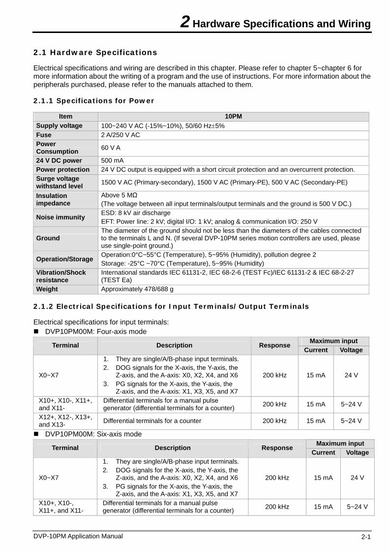
2.1 Hardware Specifications
Electrical specifications and wiring are described in this chapter. Please refer to chapter 5~chapter 6 for more information about the writing of a program and the use of instructions. For more information about the peripherals purchased, please refer to the manuals attached to them.
2.1.1 Specifications for Power
Item 10PM Supply voltage 100~240 V AC (-15%~10%), 50/60 Hz5% Fuse 2 A/250 V AC Power Consumption 60 V A
24 V DC power 500 mA Power protection 24 V DC output is equipped with a short circuit protection and an overcurrent protection. Surge voltage withstand level 1500 V AC (Primary-secondary), 1500 V AC (Primary-PE), 500 V AC (Secondary-PE)
Insulation impedance
Above 5 MΩ (The voltage between all input terminals/output terminals and the ground is 500 V DC.)
Noise immunity ESD: 8 kV air discharge EFT: Power line: 2 kV; digital I/O: 1 kV; analog & communication I/O: 250 V
Ground The diameter of the ground should not be less than the diameters of the cables connected to the terminals L and N. (If several DVP-10PM series motion controllers are used, please use single-point ground.)
Operation/Storage Operation:0°C~55°C (Temperature), 5~95% (Humidity), pollution degree 2 Storage: -25°C ~70°C (Temperature), 5~95% (Humidity)
Vibration/Shock resistance
International standards IEC 61131-2, IEC 68-2-6 (TEST Fc)/IEC 61131-2 & IEC 68-2-27 (TEST Ea)
Weight Approximately 478/688 g
2.1.2 Electrical Specifications for Input Terminals/Output Terminals
Electrical specifications for input terminals: DVP10PM00M: Four-axis mode
Maximum input Terminal Description Response Current Voltage
X0~X7
1. They are single/A/B-phase input terminals. 2. DOG signals for the X-axis, the Y-axis, the
Z-axis, and the A-axis: X0, X2, X4, and X6 3. PG signals for the X-axis, the Y-axis, the
Z-axis, and the A-axis: X1, X3, X5, and X7
200 kHz 15 mA 24 V
X10+, X10-, X11+, and X11-
Differential terminals for a manual pulse generator (differential terminals for a counter) 200 kHz 15 mA 5~24 V
X12+, X12-, X13+, and X13- Differential terminals for a counter 200 kHz 15 mA 5~24 V
DVP10PM00M: Six-axis mode Maximum input Terminal Description Response
Current Voltage
X0~X7
1. They are single/A/B-phase input terminals. 2. DOG signals for the X-axis, the Y-axis, the
Z-axis, and the A-axis: X0, X2, X4, and X6 3. PG signals for the X-axis, the Y-axis, the
Z-axis, and the A-axis: X1, X3, X5, and X7
200 kHz 15 mA 24 V
X10+, X10-, X11+, and X11-
Differential terminals for a manual pulse generator (differential terminals for a counter) 200 kHz 15 mA 5~24 V
DVP-10PM Application Manual 2-1
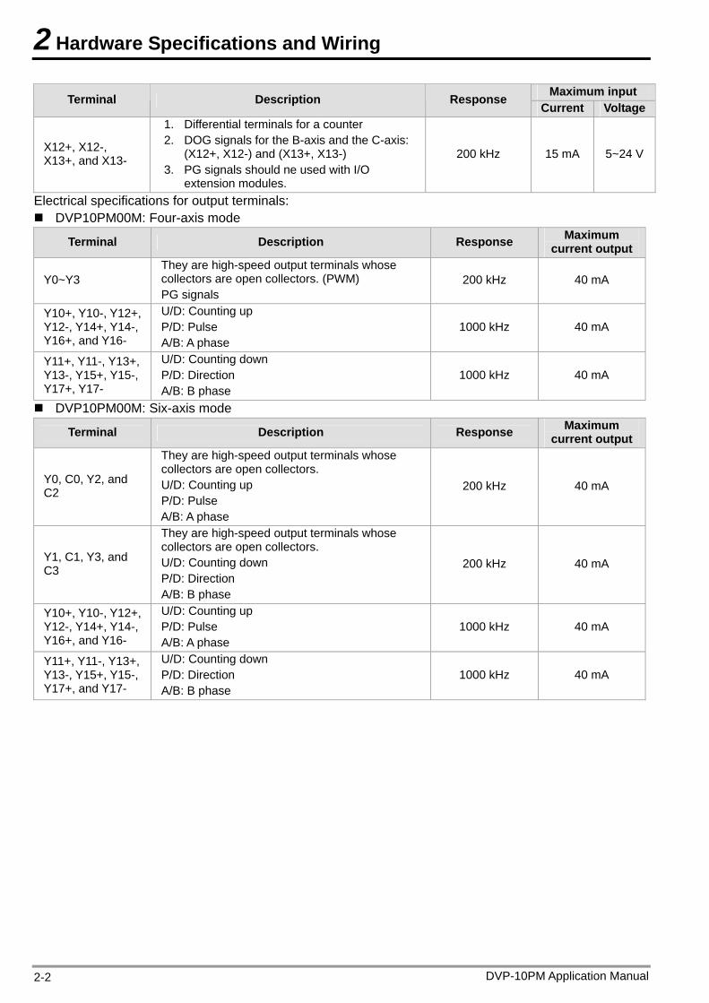
2 Hardware Specifications and Wiring
DVP-10PM Application Manual 2-2
Maximum input Terminal Description Response Current Voltage
X12+, X12-, X13+, and X13-
1. Differential terminals for a counter 2. DOG signals for the B-axis and the C-axis:
(X12+, X12-) and (X13+, X13-) 3. PG signals should ne used with I/O
extension modules.
200 kHz 15 mA 5~24 V
Electrical specifications for output terminals: DVP10PM00M: Four-axis mode
Terminal Description Response Maximum current output
Y0~Y3 They are high-speed output terminals whose collectors are open collectors. (PWM) PG signals
200 kHz 40 mA
Y10+, Y10-, Y12+, Y12-, Y14+, Y14-, Y16+, and Y16-
U/D: Counting up P/D: Pulse A/B: A phase
1000 kHz 40 mA
Y11+, Y11-, Y13+, Y13-, Y15+, Y15-, Y17+, Y17-
U/D: Counting down P/D: Direction A/B: B phase
1000 kHz 40 mA
DVP10PM00M: Six-axis mode
Terminal Description Response Maximum current output
Y0, C0, Y2, and C2
They are high-speed output terminals whose collectors are open collectors. U/D: Counting up P/D: Pulse A/B: A phase
200 kHz 40 mA
Y1, C1, Y3, and C3
They are high-speed output terminals whose collectors are open collectors. U/D: Counting down P/D: Direction A/B: B phase
200 kHz 40 mA
Y10+, Y10-, Y12+, Y12-, Y14+, Y14-, Y16+, and Y16-
U/D: Counting up P/D: Pulse A/B: A phase
1000 kHz 40 mA
Y11+, Y11-, Y13+, Y13-, Y15+, Y15-, Y17+, and Y17-
U/D: Counting down P/D: Direction A/B: B phase
1000 kHz 40 mA
2 Hardware Specifications and Wiring
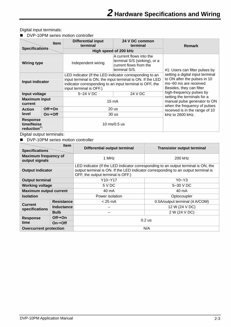
Digital input terminals: DVP-10PM series motion controller
Differential input terminal
24 V DC common terminal Item
Specifications High speed of 200 kHz Remark
Wiring type Independent wiring
A current flows into the terminal S/S (sinking), or a current flows from the terminal S/S.
Input indicator LED indicator (If the LED indicator corresponding to an input terminal is ON, the input terminal is ON. If the LED indicator corresponding to an input terminal is OFF, the input terminal is OFF.)
Input voltage 5~24 V DC 24 V DC Maximum input current 15 mA
OffOn 20 us Action level OnOff 30 us Response time/Noise reduction#1
10 ms/0.5 us
#1: Users can filter pulses by setting a digital input terminal to ON after the pulses in 10 ms~60 ms are received. Besides, they can filter high-frequency pulses by setting the terminals for a manual pulse generator to ON when the frequency of pulses received is in the range of 10 kHz to 2600 kHz.
Digital output terminals: DVP-10PM series motion controller
ItemSpecifications Differential output terminal Transistor output terminal
Maximum frequency of output signals 1 MHz 200 kHz
Output indicator LED indicator (If the LED indicator corresponding to an output terminal is ON, the output terminal is ON. If the LED indicator corresponding to an output terminal is OFF, the output terminal is OFF.)
Output terminal Y10~Y17 Y0~Y3 Working voltage 5 V DC 5~30 V DC Maximum output current 40 mA 40 mA Isolation Power isolation Optocoupler
Resistance < 25 mA 0.5A/output terminal (4 A/COM) Inductance -- 12 W (24 V DC) Current
specifications Bulb -- 2 W (24 V DC) OffOn Response
time OnOff 0.2 us
Overcurrent protection N/A
DVP-10PM Application Manual 2-3
2 Hardware Specifications and Wiring
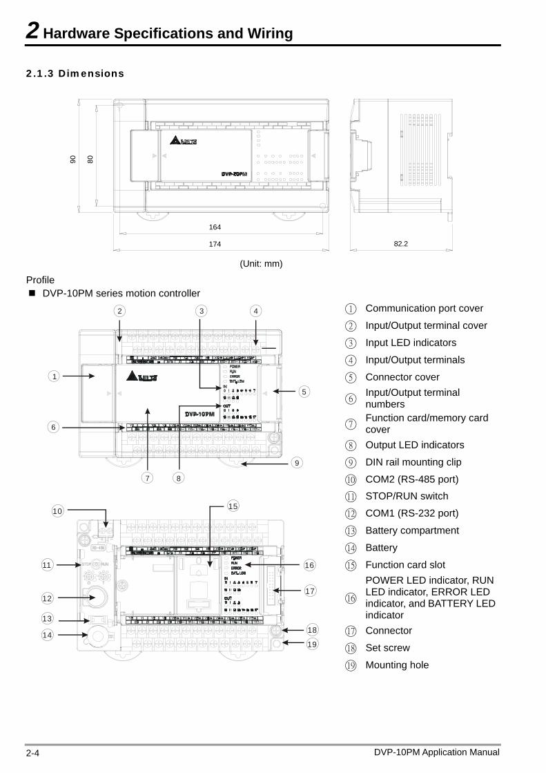
2.1.3 Dimensions
174
164
80
82.2
90
(Unit: mm)
Profile DVP-10PM series motion controller
1 Communication port cover
2 Input/Output terminal cover
3 Input LED indicators
4 Input/Output terminals
5 Connector cover
6Input/Output terminal numbers
7Function card/memory card cover
8 Output LED indicators
9 DIN rail mounting clip 9
8
6
4
7
5
2
1
3
10 COM2 (RS-485 port)
11 STOP/RUN switch
12 COM1 (RS-232 port)
13 Battery compartment
14 Battery
15 Function card slot
16
POWER LED indicator, RUN LED indicator, ERROR LED indicator, and BATTERY LED indicator
17 Connector
18 Set screw
10
11
12
13
14
15
16
17
18
19
19 Mounting hole
DVP-10PM Application Manual 2-4
2 Hardware Specifications and Wiring
DVP-10PM Application Manual 2-5
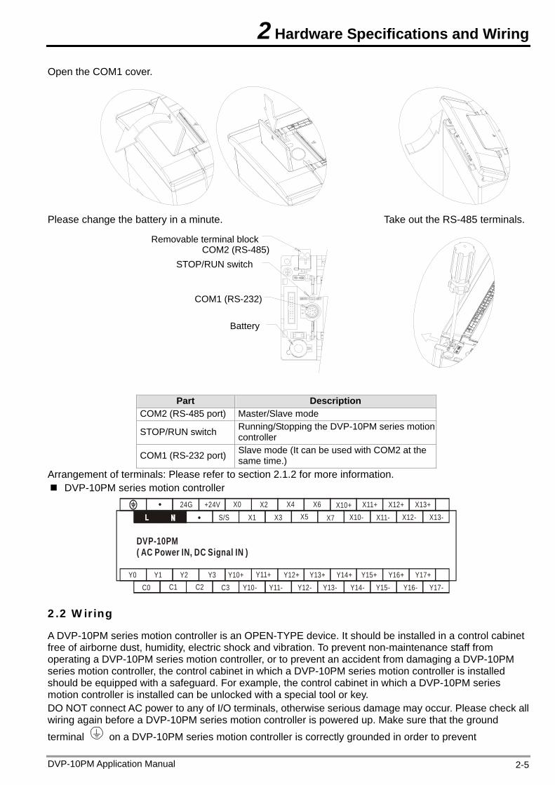
Open the COM1 cover.
Please change the battery in a minute. Take out the RS-485 terminals.
Part Description
COM2 (RS-485 port) Master/Slave mode
STOP/RUN switch Running/Stopping the DVP-10PM series motion controller
COM1 (RS-232 port) Slave mode (It can be used with COM2 at the same time.)
Arrangement of terminals: Please refer to section 2.1.2 for more information. DVP-10PM series motion controller
S/S24G
X1 X3 X5 X7 X10- X11- X12- X13-+24V X0 X2 X4 X6 X10+ X11+ X12+ X13+
C3 Y10- Y11- Y12- Y13- Y14- Y15- Y16- Y17- Y10+ Y11+ Y12+ Y13+ Y14+ Y15+ Y16+ Y17+Y0 Y1 Y2 Y3
C2C1C0
DVP-10PM( AC Power IN, DC Signal IN )
2.2 Wiring
A DVP-10PM series motion controller is an OPEN-TYPE device. It should be installed in a control cabinet free of airborne dust, humidity, electric shock and vibration. To prevent non-maintenance staff from operating a DVP-10PM series motion controller, or to prevent an accident from damaging a DVP-10PM series motion controller, the control cabinet in which a DVP-10PM series motion controller is installed should be equipped with a safeguard. For example, the control cabinet in which a DVP-10PM series motion controller is installed can be unlocked with a special tool or key. DO NOT connect AC power to any of I/O terminals, otherwise serious damage may occur. Please check all wiring again before a DVP-10PM series motion controller is powered up. Make sure that the ground terminal on a DVP-10PM series motion controller is correctly grounded in order to prevent
Battery
COM1 (RS-232)
STOP/RUN switchCOM2 (RS-485)
Removable terminal block
2 Hardware Specifications and Wiring
electromagnetic interference.
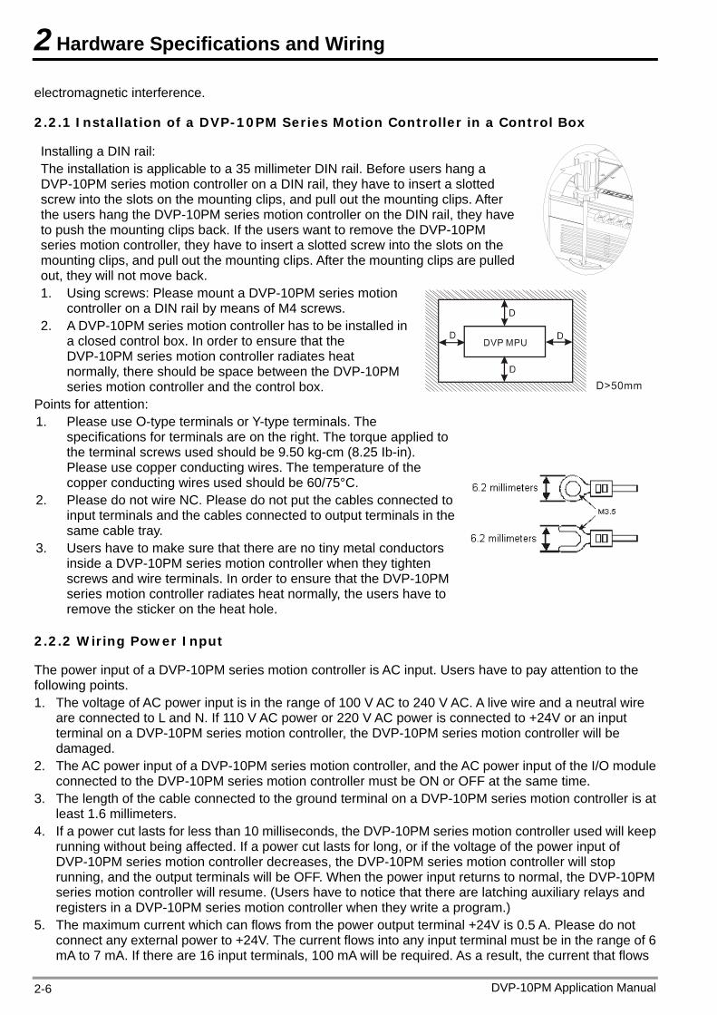
2.2.1 Installation of a DVP-10PM Series Motion Controller in a Control Box
Installing a DIN rail: The installation is applicable to a 35 millimeter DIN rail. Before users hang a DVP-10PM series motion controller on a DIN rail, they have to insert a slotted screw into the slots on the mounting clips, and pull out the mounting clips. After the users hang the DVP-10PM series motion controller on the DIN rail, they have to push the mounting clips back. If the users want to remove the DVP-10PM series motion controller, they have to insert a slotted screw into the slots on the mounting clips, and pull out the mounting clips. After the mounting clips are pulled out, they will not move back. 1. Using screws: Please mount a DVP-10PM series motion
controller on a DIN rail by means of M4 screws. 2. A DVP-10PM series motion controller has to be installed in
a closed control box. In order to ensure that the DVP-10PM series motion controller radiates heat normally, there should be space between the DVP-10PM series motion controller and the control box.
Points for attention: 1. Please use O-type terminals or Y-type terminals. The
specifications for terminals are on the right. The torque applied to the terminal screws used should be 9.50 kg-cm (8.25 Ib-in). Please use copper conducting wires. The temperature of the copper conducting wires used should be 60/75°C.
2. Please do not wire NC. Please do not put the cables connected to input terminals and the cables connected to output terminals in the same cable tray.
3. Users have to make sure that there are no tiny metal conductors inside a DVP-10PM series motion controller when they tighten screws and wire terminals. In order to ensure that the DVP-10PM series motion controller radiates heat normally, the users have to remove the sticker on the heat hole.
2.2.2 Wiring Power Input
The power input of a DVP-10PM series motion controller is AC input. Users have to pay attention to the following points. 1. The voltage of AC power input is in the range of 100 V AC to 240 V AC. A live wire and a neutral wire
are connected to L and N. If 110 V AC power or 220 V AC power is connected to +24V or an input terminal on a DVP-10PM series motion controller, the DVP-10PM series motion controller will be damaged.
2. The AC power input of a DVP-10PM series motion controller, and the AC power input of the I/O module connected to the DVP-10PM series motion controller must be ON or OFF at the same time.
3. The length of the cable connected to the ground terminal on a DVP-10PM series motion controller is at least 1.6 millimeters.
4. If a power cut lasts for less than 10 milliseconds, the DVP-10PM series motion controller used will keep running without being affected. If a power cut lasts for long, or if the voltage of the power input of DVP-10PM series motion controller decreases, the DVP-10PM series motion controller will stop running, and the output terminals will be OFF. When the power input returns to normal, the DVP-10PM series motion controller will resume. (Users have to notice that there are latching auxiliary relays and registers in a DVP-10PM series motion controller when they write a program.)
5. The maximum current which can flows from the power output terminal +24V is 0.5 A. Please do not connect any external power to +24V. The current flows into any input terminal must be in the range of 6 mA to 7 mA. If there are 16 input terminals, 100 mA will be required. As a result, the current that flows
DVP-10PM Application Manual 2-6
2 Hardware Specifications and Wiring
from +24 V to an external load can not be greater than 400 mA.
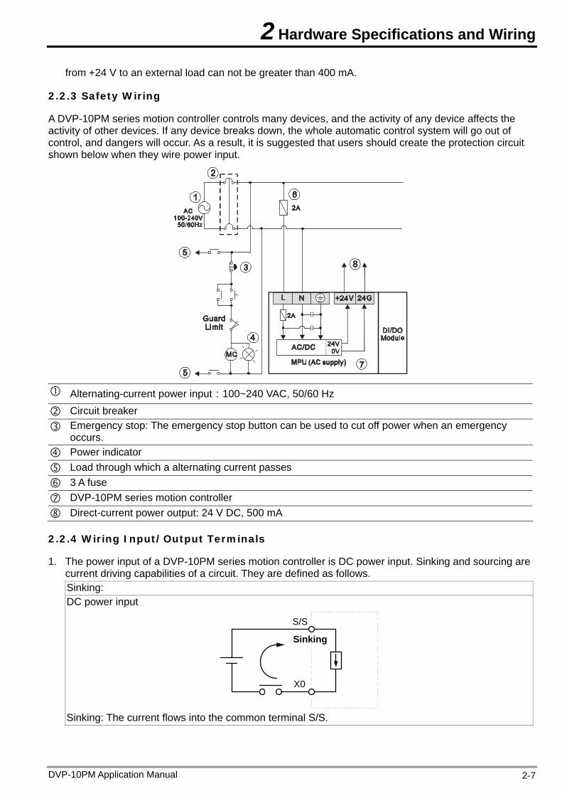
2.2.3 Safety Wiring
A DVP-10PM series motion controller controls many devices, and the activity of any device affects the activity of other devices. If any device breaks down, the whole automatic control system will go out of control, and dangers will occur. As a result, it is suggested that users should create the protection circuit shown below when they wire power input.
Alternating-current power input:100~240 VAC, 50/60 Hz
Circuit breaker Emergency stop: The emergency stop button can be used to cut off power when an emergency
occurs. Power indicator Load through which a alternating current passes 3 A fuse DVP-10PM series motion controller Direct-current power output: 24 V DC, 500 mA
2.2.4 Wiring Input/Output Terminals
1. The power input of a DVP-10PM series motion controller is DC power input. Sinking and sourcing are current driving capabilities of a circuit. They are defined as follows. Sinking: DC power input
S/S
X0
Sinking
Sinking: The current flows into the common terminal S/S.
DVP-10PM Application Manual 2-7
2 Hardware Specifications and Wiring
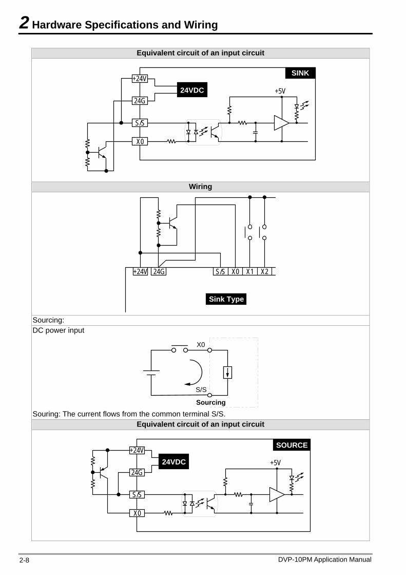
Equivalent circuit of an input circuit
24VDC24G
X0
S/S
+24VSINK
+5V
Wiring
24G S/S X0 X1 X2+24V
Sink Type
Sourcing: DC power input
S/S
X0
Sourcing Souring: The current flows from the common terminal S/S.
Equivalent circuit of an input circuit
24VDC24G
X0
S/S
+24VSOURCE
+5V
DVP-10PM Application Manual 2-8
2 Hardware Specifications and Wiring
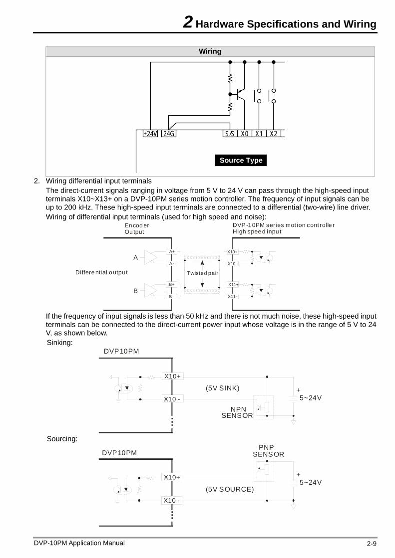
Wiring
24G S/S X0 X1 X2+24V
Source Type
2. Wiring differential input terminals The direct-current signals ranging in voltage from 5 V to 24 V can pass through the high-speed input terminals X10~X13+ on a DVP-10PM series motion controller. The frequency of input signals can be up to 200 kHz. These high-speed input terminals are connected to a differential (two-wire) line driver. Wiring of differential input terminals (used for high speed and noise):
En cod er Ou tput
DVP-1 0PM series mot ion cont rolle rHigh spee d inpu t
Twisted pai rDiffere ntial o utpu t
AA+
A -
B -
B+
X10+
X10 -
X11+
X11 -B
If the frequency of input signals is less than 50 kHz and there is not much noise, these high-speed input terminals can be connected to the direct-current power input whose voltage is in the range of 5 V to 24 V, as shown below. Sinking:
(5V SINK)
NPNSENSOR
+5~24V
X10+
X10 -
DVP10PM
Sourcing:
(5V SOURCE)
+5~24V
PNPSENSOR
X10+
X10 -
DVP10PM
DVP-10PM Application Manual 2-9
2 Hardware Specifications and Wiring
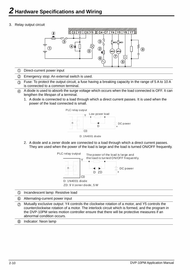
3. Relay output circuit
Direct-current power input
Emergency stop: An external switch is used.
Fuse: To protect the output circuit, a fuse having a breaking capacity in the range of 5 A to 10 A is connected to a common terminal.
A diode is used to absorb the surge voltage which occurs when the load connected is OFF. It can lengthen the lifespan of a terminal. 1. A diode is connected to a load through which a direct current passes. It is used when the
power of the load connected is small.
+DR
Y
C0
D: 1N4001 diode
DC power
Low-power loadPLC relay output
2. A diode and a zener diode are connected to a load through which a direct current passes. They are used when the power of the load is large and the load is turned ON/OFF frequently.
D: 1N4001 diode
DC power
PLC relay output
ZDDR
+
Y
C0
ZD: 9 V zener d iode, 5 W
The power of the load is large andthe load is turned ON/OFF frequently.
Incandescent lamp: Resistive load
Alternating-current power input
Mutually exclusive output: Y4 controls the clockwise rotation of a motor, and Y5 controls the counterclockwise rotation of a motor. The interlock circuit which is formed, and the program in the DVP-10PM series motion controller ensure that there will be protective measures if an abnormal condition occurs.
Indicator: Neon lamp
DVP-10PM Application Manual 2-10
2 Hardware Specifications and Wiring
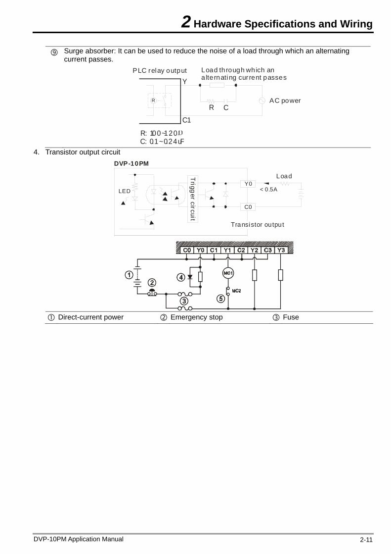
Surge absorber: It can be used to reduce the noise of a load through which an alternating current passes.
AC power
PLC relay output
R C
R: 100~120C: 0.1~0.24uF
R
Y
C1
Load through which an a lternating cur rent passes
4. Transistor output circuit
Y0LED
C0
DVP-10PM
< 0.5A
Trigg
er circuit
Transistor output
Load
Direct-current power Emergency stop Fuse
DVP-10PM Application Manual 2-11
2 Hardware Specifications and Wiring
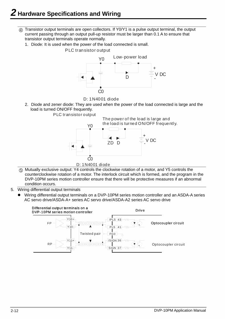
Transistor output terminals are open collectors. If Y0/Y1 is a pulse output terminal, the output current passing through an output pull-up resistor must be larger than 0.1 A to ensure that transistor output terminals operate normally. 1. Diode: It is used when the power of the load connected is small.
D: 1N4001 diode
Low-power loadPLC transistor output
V DC+
D
Y0
-
C0
2. Diode and zener diode: They are used when the power of the load connected is large and the
load is turned ON/OFF frequently.
ZD D V DC+
Y0
-
C0D: 1N4001 diode
PLC transistor outputThe power o f the load is large andthe load is turned ON/OFF frequently.
Mutually exclusive output: Y4 controls the clockwise rotation of a motor, and Y5 controls the
counterclockwise rotation of a motor. The interlock circuit which is formed, and the program in the DVP-10PM series motion controller ensure that there will be protective measures if an abnormal condition occurs.
5. Wiring differential output terminals Wiring differential output terminals on a DVP-10PM series motion controller and an ASDA-A series
AC servo drive/ASDA-A+ series AC servo drive/ASDA-A2 series AC servo drive
/PLS
PLS
/SIGN
SIGN
FP
RP
Y10+
Y10-
Y11+
Y11-
FG0
43
41
36
37
Differential output terminals on a DVP-10PM ser ies motion controllerDifferential output terminals on a DVP-10PM ser ies motion controllerDifferential output terminals on a DVP-10PM ser ies motion controller DriveDrive
Optocoupler circuitOptocoupler circuit
Optocoupler circuit
Twisted pair
DVP-10PM Application Manual 2-12
2 Hardware Specifications and Wiring
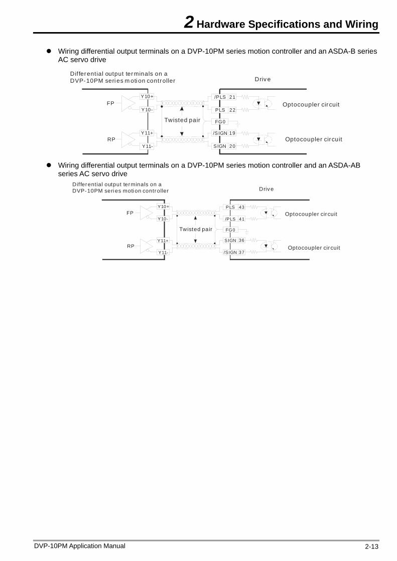
Wiring differential output terminals on a DVP-10PM series motion controller and an ASDA-B series AC servo drive
Differential output terminals on a DVP-10PM seri es m oti on controller Drive
Optocoupler circuit
Optocoupler circuit
Twisted pair
/PLS
PLS
/SIGN
SIGN
FP
RP
Y10+
Y10-
Y11+
Y11-
FG0
21
22
19
20
Wiring differential output terminals on a DVP-10PM series motion controller and an ASDA-AB series AC servo drive
Differential output terminals on a DVP-10PM seri es moti on controller Drive
Optocoupler cir cuit
Optocoupler cir cuit
Twisted pair
PLS
/PLS
SIGN
/SIGN
FP
RP
Y10+
Y10-
Y11+
Y11-
FG0
43
41
36
37
DVP-10PM Application Manual 2-13
2 Hardware Specifications and Wiring
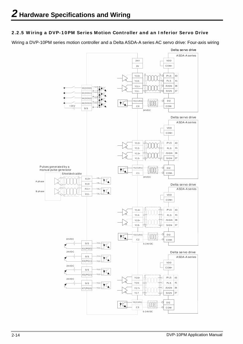
2.2.5 Wiring a DVP-10PM Series Motion Controller and an Inferior Servo Drive
Wiring a DVP-10PM series motion controller and a Delta ASDA-A series AC servo drive: Four-axis wiring
Y1 0+
Y1 0-
Y11 +
Y11 -
Y0( CLR0)
C0
A ph aseX1 0+
X1 0-
X11 +
/P LS
B ph aseX11 -
+24 V
24 V
0V
/S IGN
SI GN
VDD
COM+
PL S
24 VDC
DI2
COM-
SI GN
COM-
VDD
COM+
DI2
24 VDC
PL S
/P LS
/S IGN
Y1 2+
Y1 2-
Y1 3+
Y1 3-
Y1( CLR1)
C1
X0( DOG0)
ASDA-A series
SI GN
VDD
COM+
PL S
/P LS
/S IGN
Y1 4+
Y1 4-
Y1 5+
Y1 5-
S/ S
COM-
DI2
5-2 4V DC
Y2( CLR2)
C2
43
36
37
41
43
36
37
41
43
36
37
41
SI GN
VDD
COM+
PL S
/P LS
/S IGN
Y1 6+
Y1 6-
Y1 7+
Y1 7
COM-
DI2
5-2 4V DC
Y3( CLR3)
C3
43
36
37
41
S/ S
24 VDC
S/ S
X1 (PG0 )
S/ S
S/ S
24 VDC
24 VDC
24 VDC
X2( DOG1)
X4( DOG2)
X6( DOG3)
X3 (PG1 )
X5 (PG2 )
X7 (PG3 )
Delta se rvo drive
Delta se rvo drive
Delta se rvo drive
Delta se rvo drive
Delta se rvo drive
ASDA-A series
ASDA-A series
ASDA-A series
Shielded cable
Pulses generated by a manual pu lse generator
DVP-10PM Application Manual 2-14
2 Hardware Specifications and Wiring
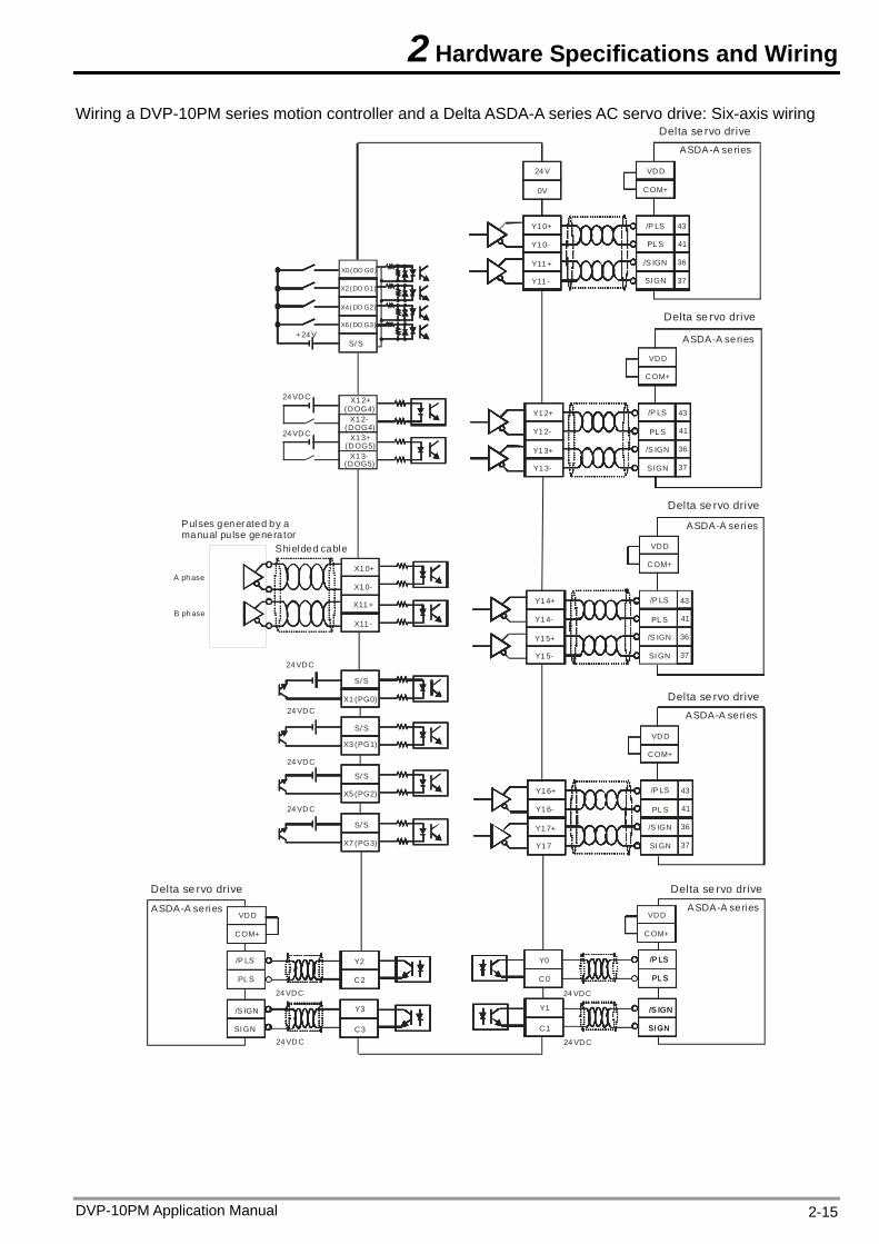
Wiring a DVP-10PM series motion controller and a Delta ASDA-A series AC servo drive: Six-axis wiring
Y1 0+
Y1 0-
Y11 +
Y11 -
X1 0+
X1 0-
X11 +
/P LS
X11 -
+24 V
24 V
0V
/S IGN
SI GN
VDD
COM+
PL S
X0( DO G0)
S/ S
43
36
37
41
SI GN
VDD
COM+
PL S
/P LS
/S IGN
Y1 2+
Y1 2-
Y1 3+
Y1 3-
43
36
37
41
SI GN
VDD
COM+
PL S
/P LS
/S IGN
Y1 4+
Y1 4-
Y1 5+
Y1 5-
43
36
37
41
SI GN
VDD
COM+
PL S
/P LS
/S IGN
Y1 6+
Y1 6-
Y1 7+
Y1 7
43
36
37
41
X2( DO G1)
X4( DO G2)
X6( DO G3)
S/ S
24 VDC
S/ S
X1 (PG0)
S/ S
S/ S
24 VDC
24 VDC
24 VDC
X3 (PG1)
X5 (PG2)
X7 (PG3)
24 VDC
24 VDC
X1 2+(DOG4)
X1 2-(DOG4)
X1 3+(DOG5)
X1 3-(DOG5)
Y0
C0
24 VDC
/P LS
PL S
/P LS
PL S
/S IGN
24 VDC
Y1
C1 SI GN
/S IGN
SI GN
VDD
COM+
VDD
COM+
/P LS
PL S
/S IGN
SI GN
24 VDC
24 VDC
Y2
C2
Y3
C3
Delta se rvo driveASDA-A series
Delta se rvo drive
ASDA-A series
ASDA-A series
Delta se rvo drive
ASDA-A series
Delta se rvo drive
ASDA-A series
Delta se rvo driveDelta se rvo drive
ASDA-A series
Shielded cable
Pulses generated by a manual pu lse generator
A ph ase
B ph ase
DVP-10PM Application Manual 2-15
2 Hardware Specifications and Wiring
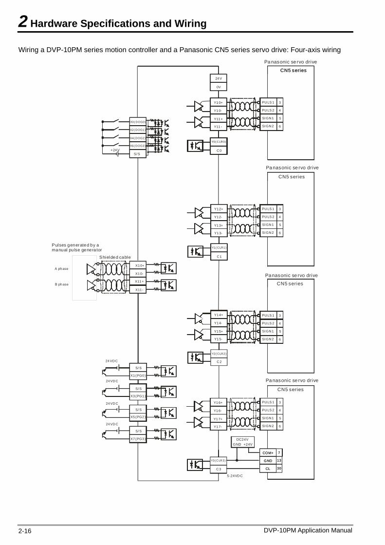
Wiring a DVP-10PM series motion controller and a Panasonic CN5 series servo drive: Four-axis wiring
Y1 0+
Y1 0-
Y11 +
Y11 -
C0
X1 0+
X1 0-
X11 +
PULS 1
X11 -
+24 V
24 V
0V
SI GN1
SI GN2
Y1 2+
Y1 2-
Y1 3+
Y1 3-
C1
Y1 4+
Y1 4-
Y1 5+
Y1 5-
S/ S
C2
3
5
6
4
Y1 6+
Y1 6-
Y1 7+
Y1 7-
C3
S/ S
24 VDC
S/ S
S/ S
S/ S
24 VDC
24 VDC
24 VDC
CN5 series
PULS 2
PULS 1
SI GN1
SI GN2
3
5
6
4PULS 2
PULS 1
SI GN1
SI GN2
3
5
6
4PULS 2
PULS 1
SI GN1
SI GN2
3
5
6
4PULS 2
5-24VD C
7
13
30
7
13
30
DC24VGND +24V
GND
COM+
GND
COM+
CLCL
X0( DOG0)
X2( DOG1)
X4( DOG2)
X6( DOG3)
X1 (PG0 )
X3 (PG1 )
X5 (PG2 )
X7 (PG3 )
Y0( CLR0)
Y1( CLR1)
Y2( CLR2)
Y3( CLR3)
Pa nasonic se rvo drive
Pa nasonic se rvo drive
CN5 series
CN5 series
CN5 series
Pa nasonic se rvo drive
Pa nasonic se rvo drive
CN5 series
A ph ase
B ph ase
Pulses generated by a manual pu lse generator
Shielded cable
DVP-10PM Application Manual 2-16
2 Hardware Specifications and Wiring
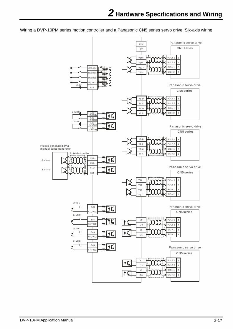
Wiring a DVP-10PM series motion controller and a Panasonic CN5 series servo drive: Six-axis wiring
Y1 0+
Y1 0-
Y11 +
Y11 -
X1 0+
X1 0-
X11 +
PULS 1
X11 -
+24 V
24 V
0V
SI GN1
SI GN2
Y1 2+
Y1 2-
Y1 3+
Y1 3-
Y1 4+
Y1 4-
Y1 5+
Y1 5-
S/ S
3
5
6
4
Y1 6+
Y1 6-
Y1 7+
Y1 7-
S/ S
24 VDC
S/ S
S/ S
S/ S
24 VDC
24 VDC
24 VDC
PULS 2
PULS 1
SI GN1
SI GN2
3
5
6
4PULS 2
PULS 1
SI GN1
SI GN2
3
5
6
4PULS 2
PULS 1
SI GN1
SI GN2
3
5
6
4PULS 2
X0( DOG0)
X2( DOG1)
X4( DOG2)
X6( DOG3)
X1 (PG0 )
X3 (PG1 )
X5 (PG2 )
X7 (PG3 )
24 VDC
24 VDC
X1 2+(DOG4)
X1 2-(DOG4)
X1 3+(DOG5)
X1 3-(DOG5)
PULS 1
SI GN1
SI GN2
PULS 2
PULS 1
SI GN1
SI GN2
PULS 2
Y0
C0
Y2
C2
Y1
C1
Y3
C3
3
5
6
4
3
5
6
4
Pa nasonic se rvo drive
CN5 series
CN5 series
CN5 series
Pa nasonic se rvo drive
Pa nasonic se rvo drive
CN5 series
Pa nasonic se rvo drive
CN5 series
Pa nasonic se rvo drive
CN5 series
Pa nasonic se rvo drive
A ph ase
B ph ase
Pulses generated by a manual pu lse generator
Shielded cable
DVP-10PM Application Manual 2-17
2 Hardware Specifications and Wiring
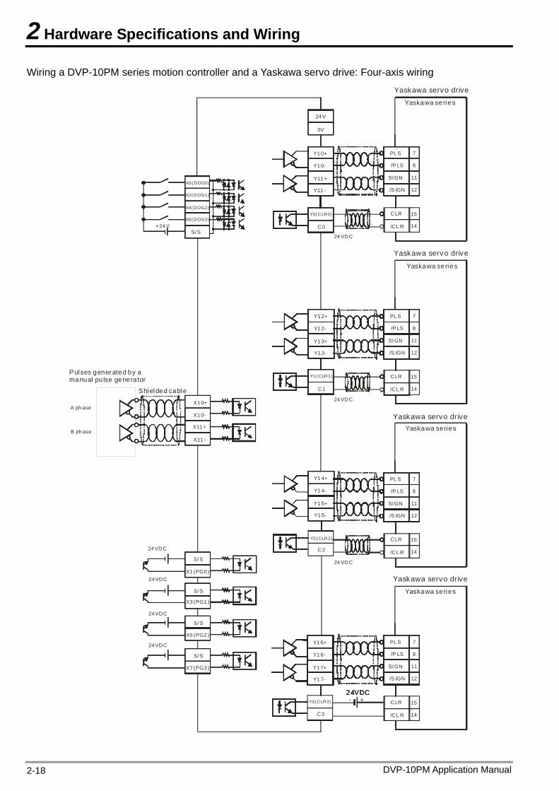
Wiring a DVP-10PM series motion controller and a Yaskawa servo drive: Four-axis wiring
Y1 0+
Y1 0-
Y11 +
Y11 -
C0
X1 0+
X1 0-
X11 +
PL S
X11 -
+24 V
24 V
0V
SI GN
/S IGN
/P LS
24 VDC
CLR
/CL R
Y1 2+
Y1 2-
Y1 3+
Y1 3-
C1
Y1 4+
Y1 4-
Y1 5+
Y1 5-
S/ S
C2
7
11
12
8
Y1 6+
Y1 6-
Y1 7+
Y1 7-
C3
S/ S
24 VDC
S/ S
S/ S
S/ S
24 VDC
24 VDC
24 VDC
Yaskawa series
14
15
PL S
SI GN
/S IGN
/P LS
24 VDC
CLR
/CL R
7
11
12
8
14
15
PL S
SI GN
/S IGN
/P LS
24 VDC
CLR
/CL R
7
11
12
8
14
15
PL S
SI GN
/S IGN
/P LS
CLR
/CL R
7
11
12
8
14
15
24VDC24VDC24VDC+-
X0( DOG0)
X2( DOG1)
X4( DOG2)
X6( DOG3)
X1 (PG0 )
X3 (PG1 )
X5 (PG2 )
X7 (PG3 )
Y0( CLR0)
Y1( CLR1)
Y2( CLR2)
Y3( CLR3)
Yaskawa servo drive
Yaskawa servo drive
Yaskawa series
Yaskawa servo driveYaskawa series
Yaskawa servo driveYaskawa series
A ph ase
B ph ase
Pulses generated by a manual pu lse generator
Shielded cable
DVP-10PM Application Manual 2-18
2 Hardware Specifications and Wiring
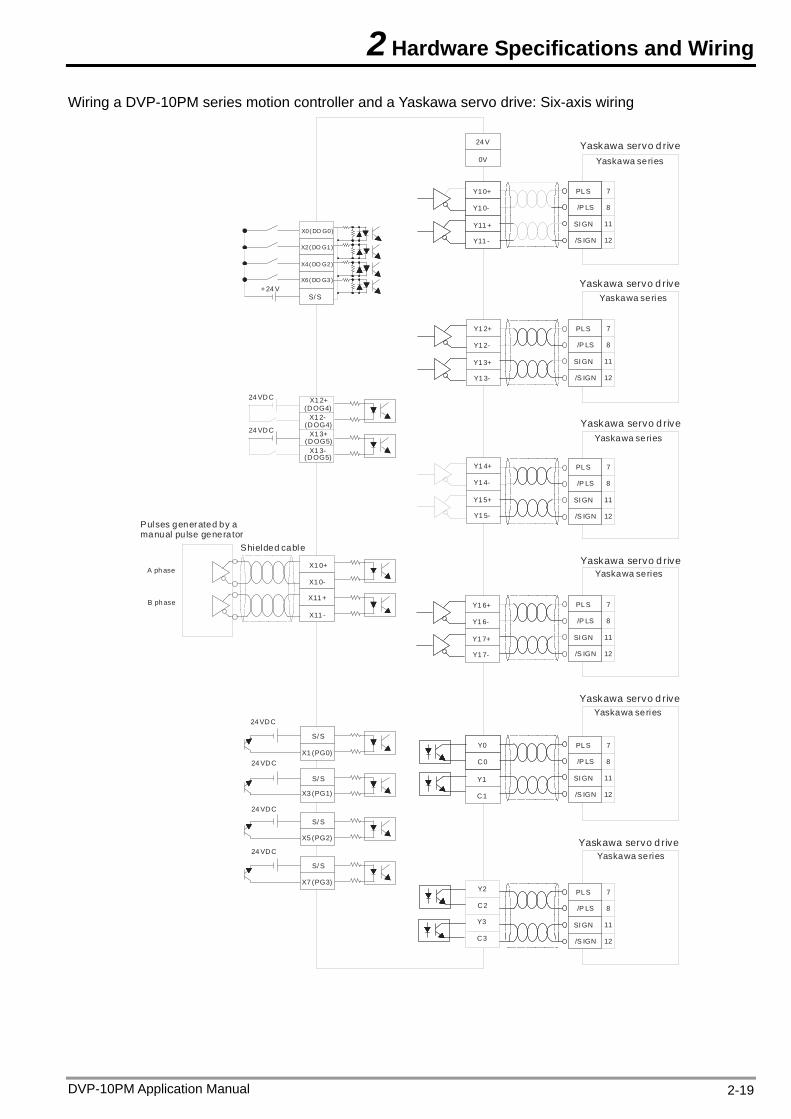
Wiring a DVP-10PM series motion controller and a Yaskawa servo drive: Six-axis wiring
Y1 0+
Y1 0-
Y11 +
Y11 -
X1 0+
X1 0-
X11 +
PL S
X11 -
+24 V
24 V
0V
SI GN
/S IGN
/P LS
Y1 2+
Y1 2-
Y1 3+
Y1 3-
Y1 4+
Y1 4-
Y1 5+
Y1 5-
S/ S
7
11
12
8
Y1 6+
Y1 6-
Y1 7+
Y1 7-
S/ S
24 VDC
S/ S
S/ S
S/ S
24 VDC
24 VDC
24 VDC
PL S
SI GN
/S IGN
/P LS
7
11
12
8
PL S
SI GN
/S IGN
/P LS
7
11
12
8
PL S
SI GN
/S IGN
/P LS
7
11
12
8
X0( DO G0)
X2( DO G1)
X4( DO G2)
X6( DO G3)
X1 (PG0)
X3 (PG1)
X5 (PG2)
X7 (PG3)
24 VDC
24 VDC
X1 2+(DOG4)
X1 2-(DOG4)
X1 3+(DOG5)
X1 3-(DOG5)
Y0
C0
Y2
C2
Y1
C1
Y3
C3
PL S
SI GN
/S IGN
/P LS
7
11
12
8
PL S
SI GN
/S IGN
/P LS
7
11
12
8
Yaskawa servo d riveYaskawa series
Yaskawa seriesYaskawa servo d rive
Yaskawa servo d riveYaskawa series
Yaskawa servo d riveYaskawa series
Yaskawa servo d riveYaskawa series
Yaskawa servo d riveYaskawa series
A ph ase
B ph ase
Pulses generated by a manual pu lse generator
Shielded cable
DVP-10PM Application Manual 2-19
2 Hardware Specifications and Wiring
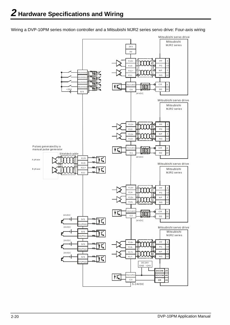
Wiring a DVP-10PM series motion controller and a Mitsubishi MJR2 series servo drive: Four-axis wiring
Y1 0+
Y1 0-
Y11 +
Y11 -
C0
X1 0+
X1 0-
X11 +
PP
X11 -
+24 V
24 V
0V
NP
NG
PG
24 VDC
CR
SG
Y1 2+
Y1 2-
Y1 3+
Y1 3-
C1
Y1 4+
Y1 4-
Y1 5+
Y1 5-
S/ S
C2
3
2
12
13
Y1 6+
Y1 6-
Y1 7+
Y1 7-
C3
S/ S
24 VDC
S/ S
S/ S
S/ S
24 VDC
24 VDC
24 VDC
10
8
MJR2 ser ies
PP
NP
NG
PG
24 VDC
CR
SG
3
2
12
13
10
8
PP
NP
NG
PG
24 VDC
CR
SG
3
2
12
13
10
8
PP
NP
NG
PG
3
2
12
13
20
46
41
20
46
41
DC 24VGND +24V
DOCOM
DICOM
DOCOM
DICOM
CRCR
5-24VDC
X0( DOG0)
X2( DOG1)
X4( DOG2)
X6( DOG3)
X1 (PG0 )
X3 (PG1 )
X5 (PG2 )
X7 (PG3 )
Y0( CLR0)
Y1( CLR1)
Y2( CLR2)
Y3( CLR3)
Mitsubishi servo driveMitsubishi
Mitsubishi servo drive
MJR2 ser iesMitsubishi
MJR2 ser iesMitsubishi
Mitsubishi servo drive
MJR2 ser iesMitsubishi
Mitsubishi servo drive
A ph ase
B ph ase
Pulses generated by a manual pu lse generator
Shielded cable
DVP-10PM Application Manual 2-20
2 Hardware Specifications and Wiring
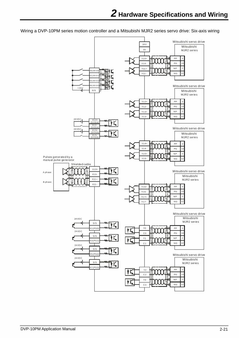
Wiring a DVP-10PM series motion controller and a Mitsubishi MJR2 series servo drive: Six-axis wiring
Y1 0+
Y1 0-
Y11 +
Y11 -
X1 0+
X1 0-
X11 +
PP
X11 -
+24 V
24 V
0V
NP
NG
PG
Y1 2+
Y1 2-
Y1 3+
Y1 3-
C1
Y1 4+
Y1 4-
Y1 5+
Y1 5-
S/ S
C2
3
2
12
13
Y1 6+
Y1 6-
Y1 7+
Y1 7-
S/ S
24 VDC
S/ S
S/ S
S/ S
24 VDC
24 VDC
24 VDC
PP
NP
NG
PG
3
2
12
13
PP
NP
NG
PG
3
2
12
13
PP
NP
NG
PG
3
2
12
13
X0( DO G0)
X2( DO G1)
X4( DO G2)
X6( DO G3)
X1 (PG0)
X3 (PG1)
X5 (PG2)
X7 (PG3)Y2
24 VDC
24 VDC
X1 2+(DOG4)
X1 2-(DOG4)
X1 3+(DOG5)
X1 3-(DOG5)
C3
Y3
C0
Y0
Y1
PP
NP
NG
PG
3
2
12
13
PP
NP
NG
PG
3
2
12
13
Mitsubishi servo drive
MJR2 ser iesMitsubishi
Mitsubishi servo drive
MJR2 ser iesMitsubishi
MJR2 ser iesMitsubishi
MJR2 ser iesMitsubishi
Mitsubishi servo drive
MJR2 ser iesMitsubishi
Mitsubishi servo drive
MJR2 ser iesMitsubishi
Mitsubishi servo drive
Mitsubishi servo drive
A ph ase
B ph ase
Pulses generated by a manual pu lse generator
Shielded cable
DVP-10PM Application Manual 2-21
2 Hardware Specifications and Wiring
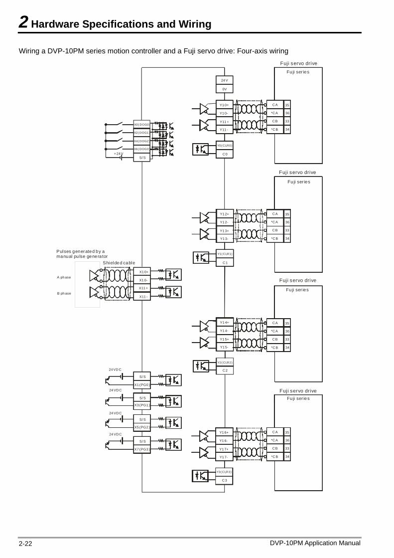
Wiring a DVP-10PM series motion controller and a Fuji servo drive: Four-axis wiring
Y1 0+
Y1 0-
Y11 +
Y11 -
C0
X1 0+
X1 0-
X11 +
CA
X11 -
+24 V
24 V
0V
CB
*CB
Y1 2+
Y1 2-
Y1 3+
Y1 3-
C1
Y1 4+
Y1 4-
Y1 5+
Y1 5-
S/ S
C2
35
33
34
36
Y1 6+
Y1 6-
Y1 7+
Y1 7-
C3
S/ S
24 VDC
S/ S
S/ S
S/ S
24 VDC
24 VDC
24 VDC
Fuji ser ies
*CA
CA
CB
*CB
35
33
34
36*CA
CA
CB
*CB
35
33
34
36*CA
CA
CB
*CB
35
33
34
36*CA
X0( DOG0)
X2( DOG1)
X4( DOG2)
X6( DOG3)
X1 (PG0 )
X3 (PG1 )
X5 (PG2 )
X7 (PG3 )
Y0( CLR0)
Y1( CLR1)
Y2( CLR2)
Y3( CLR3)
Fuji servo drive
Fuji servo drive
Fuji ser ies
Fuji servo drive
Fuji ser ies
Fuji ser iesFuji servo drive
A ph ase
B ph ase
Pulses generated by a manual pu lse generator
Shielded cable
DVP-10PM Application Manual 2-22
2 Hardware Specifications and Wiring
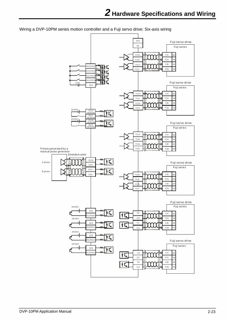
Wiring a DVP-10PM series motion controller and a Fuji servo drive: Six-axis wiring
Y1 0+
Y1 0-
Y11 +
Y11 -
C0
X1 0+
X1 0-
X11 +
CA
X11 -
+24 V
24 V
0V
CB
*CB
Y1 2+
Y1 2-
Y1 3+
Y1 3-
C1
Y1 4+
Y1 4-
Y1 5+
Y1 5-
S/ S
35
33
34
36
Y1 6+
Y1 6-
Y1 7+
Y1 7-
S/ S
24 VDC
S/ S
S/ S
S/ S
24 VDC
24 VDC
24 VDC
*CA
CA
CB
*CB
35
33
34
36*CA
CA
CB
*CB
35
33
34
36*CA
CA
CB
*CB
35
33
34
36*CA
X0( DOG0)
X2( DOG1)
X4( DOG2)
X6( DOG3)
X1 (PG0 )
X3 (PG1 )
X5 (PG2 )
X7 (PG3 )
Y0
Y1
24 VDC
24 VDC
X1 2+(DOG4)
X1 2-(DOG4)
X1 3+(DOG5)
X1 3-(DOG5)
CA
CB
*CB
35
33
34
36*CA
CA
CB
*CB
35
33
34
36*CAC2
C3
Y2
Y3
Fuji ser ies
Fuji servo drive
Fuji servo drive
Fuji ser ies
Fuji servo driveFuji ser ies
Fuji servo driveFuji ser ies
Fuji servo driveFuji ser ies
Fuji servo drive
Fuji ser ies
A ph ase
B ph ase
Pulses generated by a manual pu lse generator
Shielded cable
DVP-10PM Application Manual 2-23
2 Hardware Specifications and Wiring
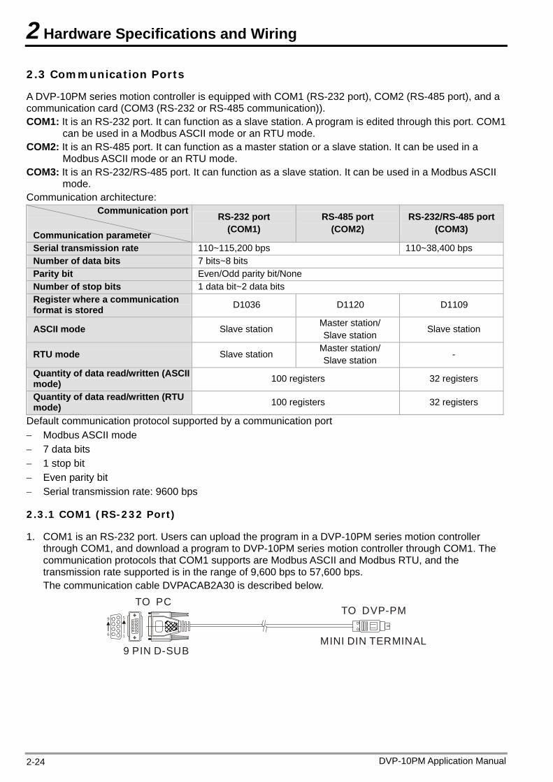
2.3 Communication Ports
A DVP-10PM series motion controller is equipped with COM1 (RS-232 port), COM2 (RS-485 port), and a communication card (COM3 (RS-232 or RS-485 communication)). COM1: It is an RS-232 port. It can function as a slave station. A program is edited through this port. COM1
can be used in a Modbus ASCII mode or an RTU mode. COM2: It is an RS-485 port. It can function as a master station or a slave station. It can be used in a
Modbus ASCII mode or an RTU mode. COM3: It is an RS-232/RS-485 port. It can function as a slave station. It can be used in a Modbus ASCII
mode. Communication architecture:
Communication port
Communication parameter
RS-232 port RS-485 port (COM2)
RS-232/RS-485 port (COM3) (COM1)
Serial transmission rate 110~115,200 bps 110~38,400 bps Number of data bits 7 bits~8 bits Parity bit Even/Odd parity bit/None Number of stop bits 1 data bit~2 data bits Register where a communication format is stored D1036 D1120 D1109
Master station/ Slave station Slave station ASCII mode Slave station Master station/ Slave station - RTU mode Slave station
Quantity of data read/written (ASCII mode) 100 registers 32 registers
Quantity of data read/written (RTU mode) 100 registers 32 registers
Default communication protocol supported by a communication port Modbus ASCII mode 7 data bits 1 stop bit Even parity bit Serial transmission rate: 9600 bps
2.3.1 COM1 (RS-232 Port)
1. COM1 is an RS-232 port. Users can upload the program in a DVP-10PM series motion controller through COM1, and download a program to DVP-10PM series motion controller through COM1. The communication protocols that COM1 supports are Modbus ASCII and Modbus RTU, and the transmission rate supported is in the range of 9,600 bps to 57,600 bps. The communication cable DVPACAB2A30 is described below.
TO PC
1
5
6
9
9 PIN D-SUB
TO DVP-PM
MINI DIN TERMINAL
DVP-10PM Application Manual 2-24
2 Hardware Specifications and Wiring
DVP-10PM Application Manual 2-25
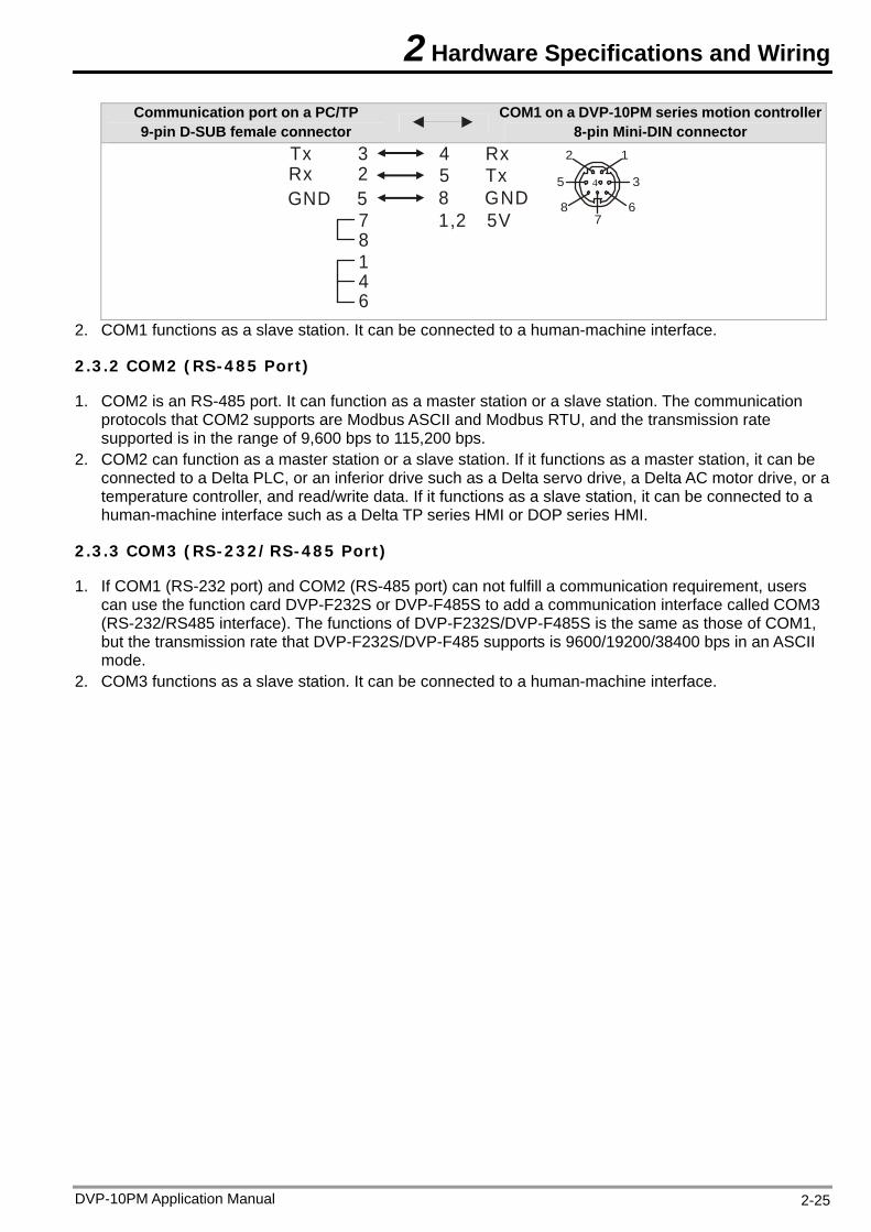
Communication port on a PC/TP 9-pin D-SUB female connector
COM1 on a DVP-10PM series motion controller8-pin Mini-DIN connector
Rx 2GND 5
12
345
67
8
4 Rx
8 GND1,2 5V
146
78
Tx 3 5 Tx
2. COM1 functions as a slave station. It can be connected to a human-machine interface.
2.3.2 COM2 (RS-485 Port)
1. COM2 is an RS-485 port. It can function as a master station or a slave station. The communication protocols that COM2 supports are Modbus ASCII and Modbus RTU, and the transmission rate supported is in the range of 9,600 bps to 115,200 bps.
2. COM2 can function as a master station or a slave station. If it functions as a master station, it can be connected to a Delta PLC, or an inferior drive such as a Delta servo drive, a Delta AC motor drive, or a temperature controller, and read/write data. If it functions as a slave station, it can be connected to a human-machine interface such as a Delta TP series HMI or DOP series HMI.
2.3.3 COM3 (RS-232/RS-485 Port)
1. If COM1 (RS-232 port) and COM2 (RS-485 port) can not fulfill a communication requirement, users can use the function card DVP-F232S or DVP-F485S to add a communication interface called COM3 (RS-232/RS485 interface). The functions of DVP-F232S/DVP-F485S is the same as those of COM1, but the transmission rate that DVP-F232S/DVP-F485 supports is 9600/19200/38400 bps in an ASCII mode.
2. COM3 functions as a slave station. It can be connected to a human-machine interface.

2 Hardware Specifications and Wiring
DVP-10PM Application Manual 2-26
MEMO
3 Devices
3.1 Device Lists
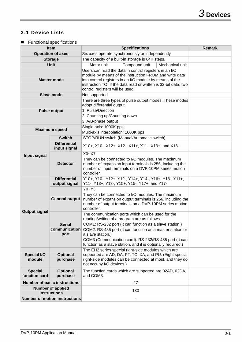
Functional specifications Item Specifications Remark
Operation of axes Six axes operate synchronously or independently. Storage The capacity of a built-in storage is 64K steps.
Unit Motor unit Compound unit Mechanical unit
Master mode
Users can read the data in control registers in an I/O module by means of the instruction FROM and write data into control registers in an I/O module by means of the instruction TO. If the data read or written is 32-bit data, two control registers will be used.
Slave mode Not supported
Pulse output
There are three types of pulse output modes. These modes adopt differential output. 1. Pulse/Direction 2. Counting up/Counting down 3. A/B-phase output
Maximum speed Single axis: 1000K pps Multi-axis interpolation: 1000K pps
Switch STOP/RUN switch (Manual/Automatic switch) Differential input signal X10+, X10-, X12+, X12-, X11+, X11-, X13+, and X13-
Input signal
Detector
X0~X7 They can be connected to I/O modules. The maximum number of expansion input terminals is 256, including the number of input terminals on a DVP-10PM series motion controller.
Differential output signal
Y10+, Y10-, Y12+, Y12-, Y14+, Y14-, Y16+, Y16-, Y11+, Y11-, Y13+, Y13-, Y15+, Y15-, Y17+, and Y17-
General output
Y0~Y3 They can be connected to I/O modules. The maximum number of expansion output terminals is 256, including the number of output terminals on a DVP-10PM series motion controller.
Output signal
Serial communication
port
The communication ports which can be used for the reading/writing of a program are as follows. COM1: RS-232 port (It can function as a slave station.) COM2: RS-485 port (It can function as a master station or a slave station.) COM3 (Communication card): RS-232/RS-485 port (It can function as a slave station, and it is optionally required.)
Special I/O module
Optional purchase
The EH2 series special right-side modules which are supported are AD, DA, PT, TC, XA, and PU. (Eight special right-side modules can be connected at most, and they do not occupy I/O devices.)
Special function card
Optional purchase
The function cards which are supported are 02AD, 02DA, and COM3.
Number of basic instructions 27 Number of applied
instructions 130
Number of motion instructions -
DVP-10PM Application Manual 3-1
3 Devices
DVP-10PM Application Manual 3-2
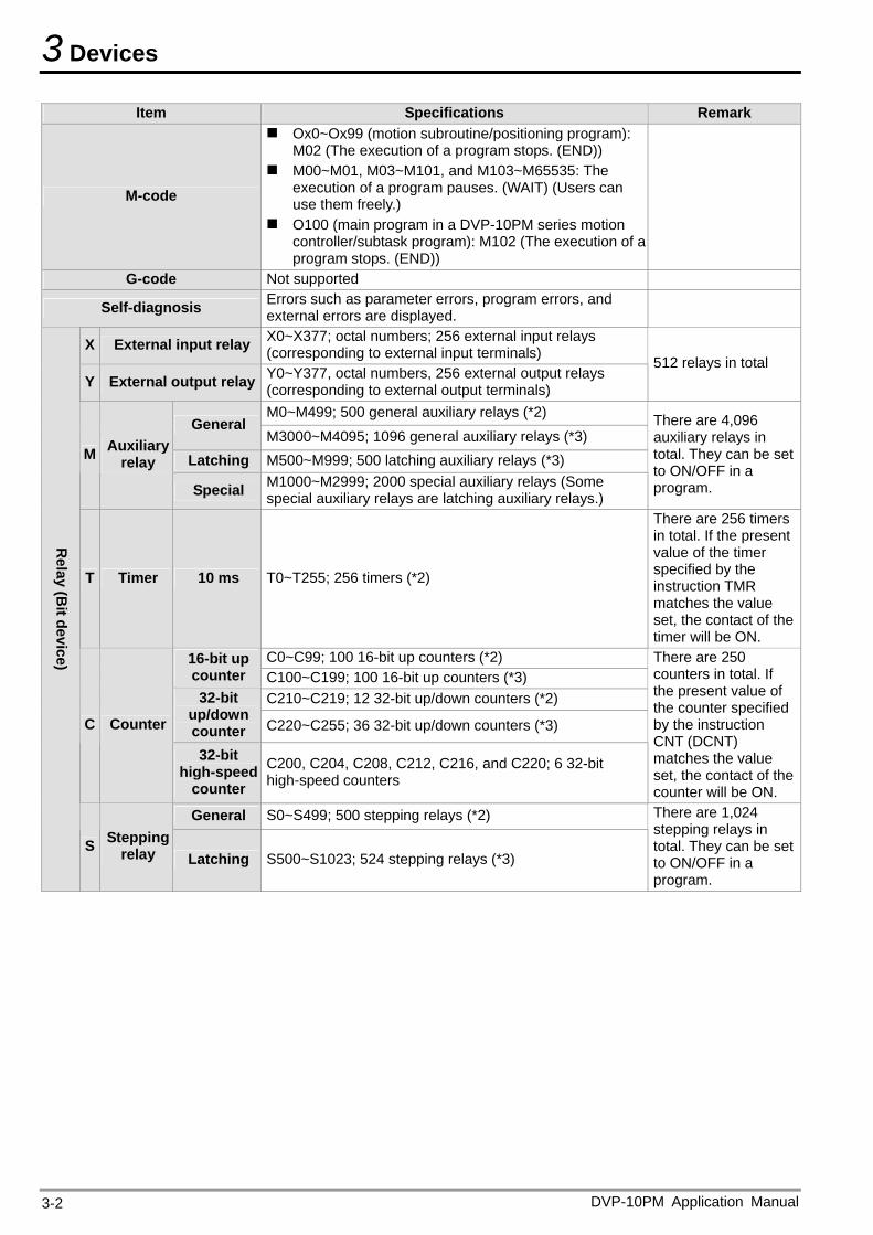
Item Specifications Remark
M-code
Ox0~Ox99 (motion subroutine/positioning program): M02 (The execution of a program stops. (END))
M00~M01, M03~M101, and M103~M65535: The execution of a program pauses. (WAIT) (Users can use them freely.)
O100 (main program in a DVP-10PM series motion controller/subtask program): M102 (The execution of a program stops. (END))
G-code Not supported
Self-diagnosis Errors such as parameter errors, program errors, and external errors are displayed.
X External input relay X0~X377; octal numbers; 256 external input relays (corresponding to external input terminals)
Y External output relay Y0~Y377, octal numbers, 256 external output relays (corresponding to external output terminals)
512 relays in total
M0~M499; 500 general auxiliary relays (*2) General
M3000~M4095; 1096 general auxiliary relays (*3) Latching M500~M999; 500 latching auxiliary relays (*3) M Auxiliary
relay
Special M1000~M2999; 2000 special auxiliary relays (Some special auxiliary relays are latching auxiliary relays.)
There are 4,096 auxiliary relays in total. They can be set to ON/OFF in a program.
T Timer 10 ms T0~T255; 256 timers (*2)
There are 256 timers in total. If the present value of the timer specified by the instruction TMR matches the value set, the contact of the timer will be ON.
C0~C99; 100 16-bit up counters (*2) 16-bit up counter C100~C199; 100 16-bit up counters (*3)
C210~C219; 12 32-bit up/down counters (*2) 32-bit up/down counter C220~C255; 36 32-bit up/down counters (*3) C Counter
32-bit high-speed
counter C200, C204, C208, C212, C216, and C220; 6 32-bit high-speed counters
There are 250 counters in total. If the present value of the counter specified by the instruction CNT (DCNT) matches the value set, the contact of the counter will be ON.
General S0~S499; 500 stepping relays (*2) R
elay (Bit device)
S Stepping relay Latching S500~S1023; 524 stepping relays (*3)
There are 1,024 stepping relays in total. They can be set to ON/OFF in a program.
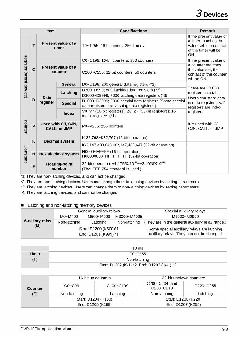
3 Devices
DVP-10PM Application Manual 3-3
Item Specifications Remark
T Present value of a timer T0~T255; 16-bit timers; 256 timers
If the present value of a timer matches the value set, the contact of the timer will be ON.
C0~C199; 16-bit counters; 200 counters
C Present value of a counter C200~C255; 32-bit counters; 56 counters
If the present value of a counter matches the value set, the contact of the counter will be ON.
General D0~D199; 200 general data registers (*2) D200~D999; 800 latching data registers (*3) Latching D3000~D9999; 7000 latching data registers (*3)
Special D1000~D2999; 2000 special data registers (Some special data registers are latching data registers.)
Register (W
ord device) D Data register
Index V0~V7 (16-bit registers); Z0~Z7 (32-bit registers); 16 index registers (*1)
There are 10,000 registers in total. Users can store data in data registers. V/Z registers are index registers.
Pointer
P Used with CJ, CJN, CALL, or JMP P0~P255; 256 pointers It is used with CJ,
CJN, CALL, or JMP.
K-32,768~K32,767 (16-bit operation) K Decimal system
K-2,147,483,648~K2,147,483,647 (32-bit operation)
H Hexadecimal system H0000~HFFFF (16-bit operation); H00000000~HFFFFFFFF (32-bit operation)
Constant
F Floating-point number
32-bit operation: ±1.1755X10-38~±3.4028X10+38 (The IEEE 754 standard is used.)
*1: They are non-latching devices, and can not be changed. *2: They are non-latching devices. Users can change them to latching devices by setting parameters. *3: They are latching devices. Users can change them to non-latching devices by setting parameters. *4: They are latching devices, and can not be changed.
Latching and non-latching memory devices
General auxiliary relays Special auxiliary relays M0~M499 M500~M999 M3000~M4095 M1000~M2999
Non-latching Latching Non-latching (They are in the general auxiliary relay range.)Auxiliary relay (M)
Start: D1200 (K500)*1 End: D1201 (K999) *1
Some special auxiliary relays are latching auxiliary relays. They can not be changed.
10 ms T0~T255
Non-latching Timer
(T) Start: D1202 (K-1) *2; End: D1203 ( K-1) *2
16-bit up counters 32-bit up/down counters
C0~C99 C100~C199 C200, C204, and C208~C219 C220~C255
Non-latching Latching Non-latching Latching Counter
(C) Start: D1204 (K100) End: D1205 (K199)
Start: D1206 (K220) End: D1207 (K255)
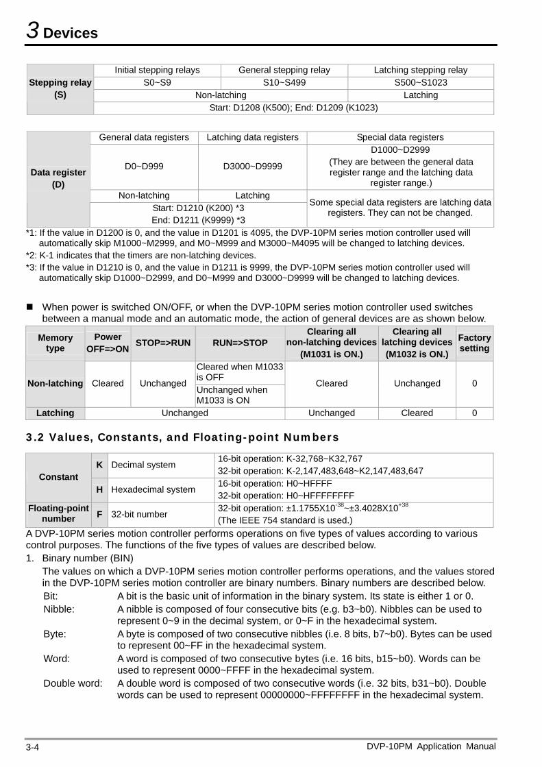
3 Devices
Initial stepping relays General stepping relay Latching stepping relay S0~S9 S10~S499 S500~S1023
Non-latching Latching Stepping relay
(S) Start: D1208 (K500); End: D1209 (K1023)
*1: If the value in D1200 is 0, and the value in D1201 is 4095, the DVP-10PM series motion controller used will automatically skip M1000~M2999, and M0~M999 and M3000~M4095 will be changed to latching devices.
General data registers Latching data registers Special data registers
D0~D999 D3000~D9999
D1000~D2999 (They are between the general data register range and the latching data
register range.) Non-latching Latching
Data register (D)
Start: D1210 (K200) *3 End: D1211 (K9999) *3
Some special data registers are latching data registers. They can not be changed.
*2: K-1 indicates that the timers are non-latching devices. *3: If the value in D1210 is 0, and the value in D1211 is 9999, the DVP-10PM series motion controller used will
automatically skip D1000~D2999, and D0~M999 and D3000~D9999 will be changed to latching devices.
When power is switched ON/OFF, or when the DVP-10PM series motion controller used switches
between a manual mode and an automatic mode, the action of general devices are as shown below.
Memory type
Power OFF=>ON STOP=>RUN RUN=>STOP
Clearing all non-latching devices
(M1031 is ON.)
Clearing all latching devices(M1032 is ON.)
Factorysetting
Cleared when M1033 is OFF Non-latching Cleared Unchanged Unchanged when M1033 is ON
Cleared Unchanged 0
Latching Unchanged Unchanged Cleared 0
3.2 Values, Constants, and Floating-point Numbers
K Decimal system 16-bit operation: K-32,768~K32,767 32-bit operation: K-2,147,483,648~K2,147,483,647 Constant
H Hexadecimal system 16-bit operation: H0~HFFFF 32-bit operation: H0~HFFFFFFFF
Floating-point number F 32-bit number 32-bit operation: ±1.1755X10-38~±3.4028X10+38
(The IEEE 754 standard is used.) A DVP-10PM series motion controller performs operations on five types of values according to various control purposes. The functions of the five types of values are described below. 1. Binary number (BIN)
The values on which a DVP-10PM series motion controller performs operations, and the values stored in the DVP-10PM series motion controller are binary numbers. Binary numbers are described below. Bit: A bit is the basic unit of information in the binary system. Its state is either 1 or 0. Nibble: A nibble is composed of four consecutive bits (e.g. b3~b0). Nibbles can be used to
represent 0~9 in the decimal system, or 0~F in the hexadecimal system. Byte: A byte is composed of two consecutive nibbles (i.e. 8 bits, b7~b0). Bytes can be used
to represent 00~FF in the hexadecimal system. Word: A word is composed of two consecutive bytes (i.e. 16 bits, b15~b0). Words can be
used to represent 0000~FFFF in the hexadecimal system. Double word: A double word is composed of two consecutive words (i.e. 32 bits, b31~b0). Double
words can be used to represent 00000000~FFFFFFFF in the hexadecimal system.
DVP-10PM Application Manual 3-4
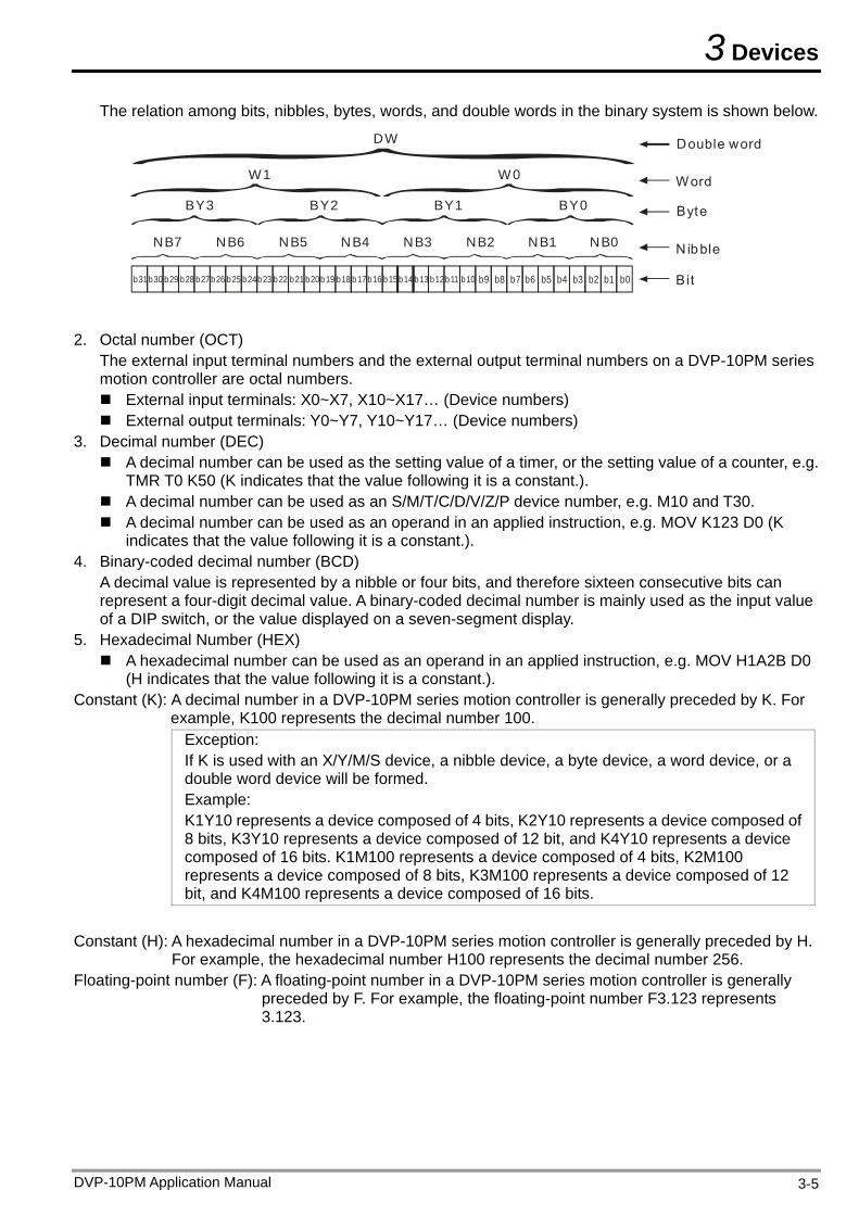
3 Devices
The relation among bits, nibbles, bytes, words, and double words in the binary system is shown below.
b31b30 b29 b28 b27b26 b25 b24b23 b22 b21 b20b19 b18 b17 b16 b15 b14 b13 b12b11 b10 b9 b8 b7 b6 b5 b4 b3 b2 b1 b0
NB0NB1NB2NB3NB4NB5NB6NB7
BY3 BY2 BY1 BY0
W1
DW
W0
Double word
Word
Byte
N ibble
Bit
2. Octal number (OCT)
The external input terminal numbers and the external output terminal numbers on a DVP-10PM series motion controller are octal numbers. External input terminals: X0~X7, X10~X17… (Device numbers) External output terminals: Y0~Y7, Y10~Y17… (Device numbers)
3. Decimal number (DEC) A decimal number can be used as the setting value of a timer, or the setting value of a counter, e.g.
TMR T0 K50 (K indicates that the value following it is a constant.). A decimal number can be used as an S/M/T/C/D/V/Z/P device number, e.g. M10 and T30. A decimal number can be used as an operand in an applied instruction, e.g. MOV K123 D0 (K
indicates that the value following it is a constant.). 4. Binary-coded decimal number (BCD)
A decimal value is represented by a nibble or four bits, and therefore sixteen consecutive bits can represent a four-digit decimal value. A binary-coded decimal number is mainly used as the input value of a DIP switch, or the value displayed on a seven-segment display.
5. Hexadecimal Number (HEX) A hexadecimal number can be used as an operand in an applied instruction, e.g. MOV H1A2B D0
(H indicates that the value following it is a constant.). Constant (K): A decimal number in a DVP-10PM series motion controller is generally preceded by K. For
example, K100 represents the decimal number 100. Exception: If K is used with an X/Y/M/S device, a nibble device, a byte device, a word device, or a double word device will be formed. Example: K1Y10 represents a device composed of 4 bits, K2Y10 represents a device composed of 8 bits, K3Y10 represents a device composed of 12 bit, and K4Y10 represents a device composed of 16 bits. K1M100 represents a device composed of 4 bits, K2M100 represents a device composed of 8 bits, K3M100 represents a device composed of 12 bit, and K4M100 represents a device composed of 16 bits.
Constant (H): A hexadecimal number in a DVP-10PM series motion controller is generally preceded by H.
For example, the hexadecimal number H100 represents the decimal number 256. Floating-point number (F): A floating-point number in a DVP-10PM series motion controller is generally
preceded by F. For example, the floating-point number F3.123 represents 3.123.
DVP-10PM Application Manual 3-5
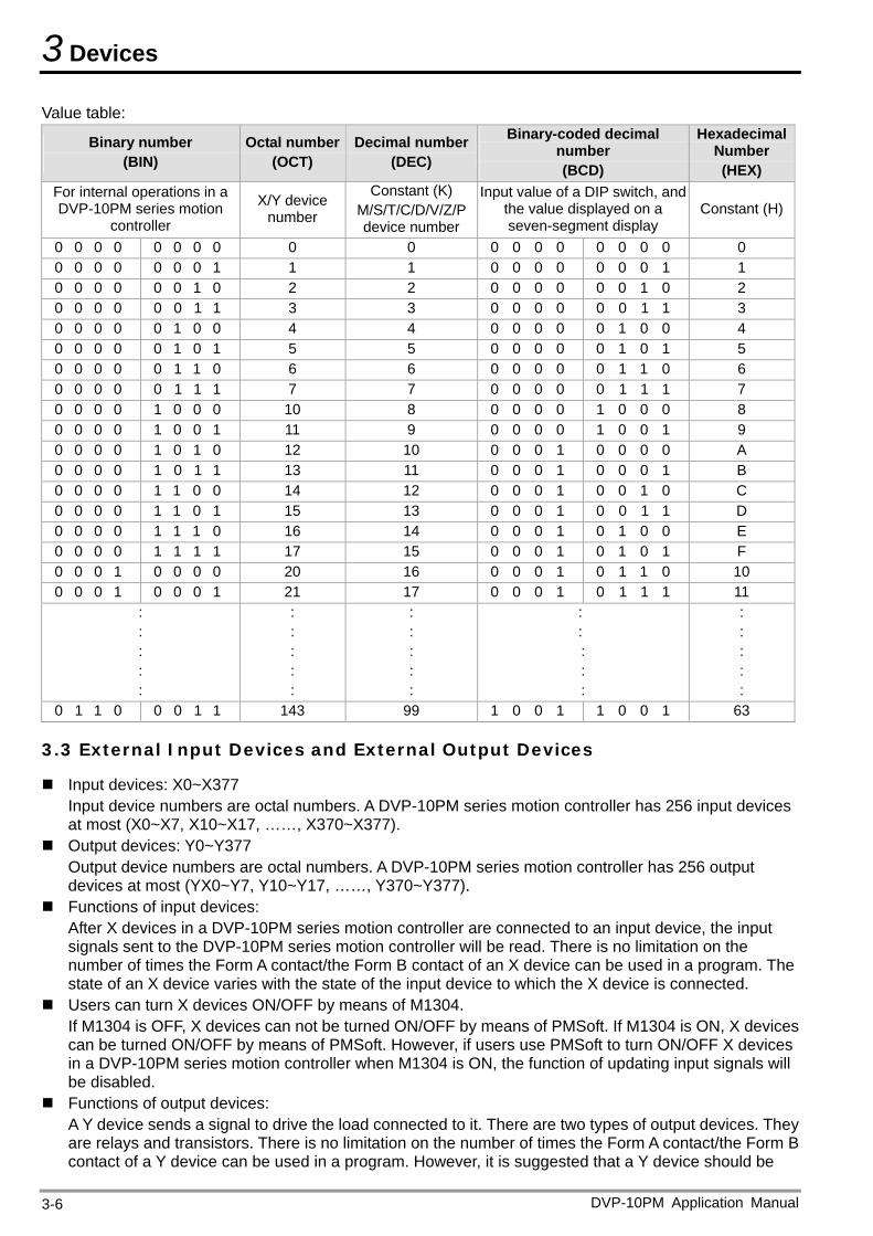
3 Devices
DVP-10PM Application Manual 3-6
Value table:
Binary number (BIN)
Octal number (OCT)
Decimal number(DEC)
Binary-coded decimal number (BCD)
Hexadecimal Number (HEX)
For internal operations in a DVP-10PM series motion
controller
X/Y device number
Constant (K) M/S/T/C/D/V/Z/P device number
Input value of a DIP switch, and the value displayed on a seven-segment display
Constant (H)
0 0 0 0 0 0 0 0 0 0 0 0 0 0 0 0 0 0 0 0 0 0 0 0 0 0 1 1 1 0 0 0 0 0 0 0 1 1 0 0 0 0 0 0 1 0 2 2 0 0 0 0 0 0 1 0 2 0 0 0 0 0 0 1 1 3 3 0 0 0 0 0 0 1 1 3 0 0 0 0 0 1 0 0 4 4 0 0 0 0 0 1 0 0 4 0 0 0 0 0 1 0 1 5 5 0 0 0 0 0 1 0 1 5 0 0 0 0 0 1 1 0 6 6 0 0 0 0 0 1 1 0 6 0 0 0 0 0 1 1 1 7 7 0 0 0 0 0 1 1 1 7 0 0 0 0 1 0 0 0 10 8 0 0 0 0 1 0 0 0 8 0 0 0 0 1 0 0 1 11 9 0 0 0 0 1 0 0 1 9 0 0 0 0 1 0 1 0 12 10 0 0 0 1 0 0 0 0 A 0 0 0 0 1 0 1 1 13 11 0 0 0 1 0 0 0 1 B 0 0 0 0 1 1 0 0 14 12 0 0 0 1 0 0 1 0 C 0 0 0 0 1 1 0 1 15 13 0 0 0 1 0 0 1 1 D 0 0 0 0 1 1 1 0 16 14 0 0 0 1 0 1 0 0 E 0 0 0 0 1 1 1 1 17 15 0 0 0 1 0 1 0 1 F 0 0 0 1 0 0 0 0 20 16 0 0 0 1 0 1 1 0 10 0 0 0 1 0 0 0 1 21 17 0 0 0 1 0 1 1 1 11
: : : : :
: : : : :
: : : : :
: : : : :
: : : : :
0 1 1 0 0 0 1 1 143 99 1 0 0 1 1 0 0 1 63
3.3 External Input Devices and External Output Devices
Input devices: X0~X377 Input device numbers are octal numbers. A DVP-10PM series motion controller has 256 input devices at most (X0~X7, X10~X17, ……, X370~X377).
Output devices: Y0~Y377 Output device numbers are octal numbers. A DVP-10PM series motion controller has 256 output devices at most (YX0~Y7, Y10~Y17, ……, Y370~Y377).
Functions of input devices: After X devices in a DVP-10PM series motion controller are connected to an input device, the input signals sent to the DVP-10PM series motion controller will be read. There is no limitation on the number of times the Form A contact/the Form B contact of an X device can be used in a program. The state of an X device varies with the state of the input device to which the X device is connected.
Users can turn X devices ON/OFF by means of M1304. If M1304 is OFF, X devices can not be turned ON/OFF by means of PMSoft. If M1304 is ON, X devices can be turned ON/OFF by means of PMSoft. However, if users use PMSoft to turn ON/OFF X devices in a DVP-10PM series motion controller when M1304 is ON, the function of updating input signals will be disabled.
Functions of output devices: A Y device sends a signal to drive the load connected to it. There are two types of output devices. They are relays and transistors. There is no limitation on the number of times the Form A contact/the Form B contact of a Y device can be used in a program. However, it is suggested that a Y device should be
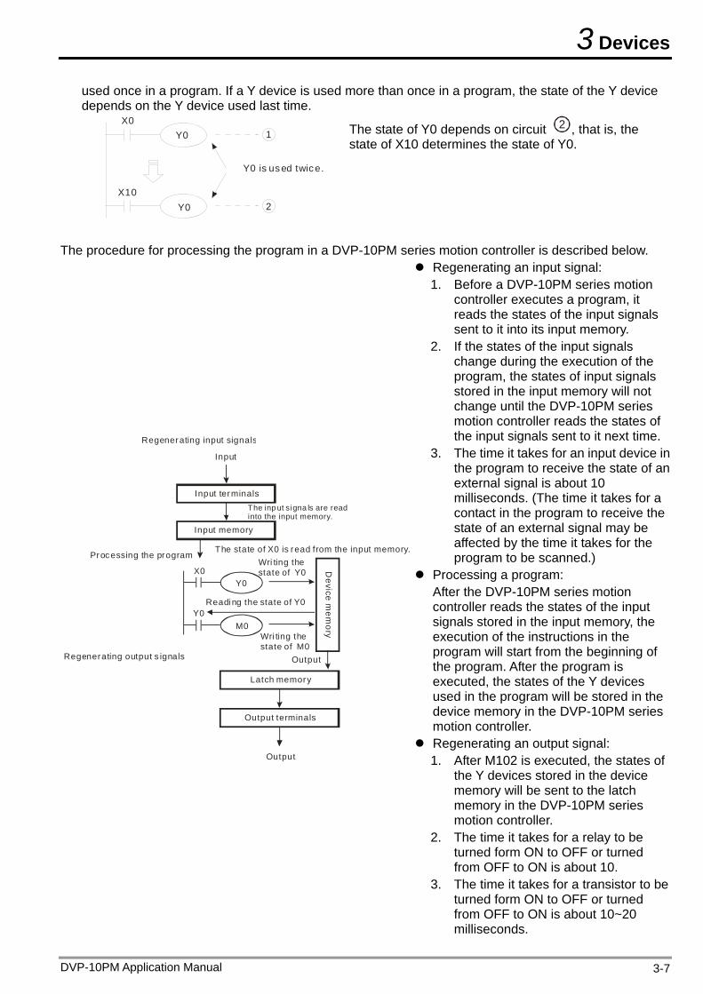
3 Devices
DVP-10PM Application Manual 3-7
used once in a program. If a Y device is used more than once in a program, the state of the Y device depends on the Y device used last time.
X0
X10
Y0
Y0
1
2
Y0 is used twice.
The state of Y0 depends on circuit 2 , that is, the state of X10 determines the state of Y0.
The procedure for processing the program in a DVP-10PM series motion controller is described below.
X0
Y0
Y0
M0
Regenerating input signals
Processing the program
Regenerating output s ignals
Input
Input terminalsThe inp ut signa ls are read into the input memory.
Input memory
The state of X0 is read from the input memory.Wri ting the state of Y0
Readi ng the state of Y0
Wri ting the state of M0
Output
Latch memory
Output terminals
Output
Device m
emory
Regenerating an input signal: 1. Before a DVP-10PM series motion
controller executes a program, it reads the states of the input signals sent to it into its input memory.
2. If the states of the input signals change during the execution of the program, the states of input signals stored in the input memory will not change until the DVP-10PM series motion controller reads the states of the input signals sent to it next time.
3. The time it takes for an input device in the program to receive the state of an external signal is about 10 milliseconds. (The time it takes for a contact in the program to receive the state of an external signal may be affected by the time it takes for the program to be scanned.)
Processing a program: After the DVP-10PM series motion controller reads the states of the input signals stored in the input memory, the execution of the instructions in the program will start from the beginning of the program. After the program is executed, the states of the Y devices used in the program will be stored in the device memory in the DVP-10PM series motion controller.
Regenerating an output signal: 1. After M102 is executed, the states of
the Y devices stored in the device memory will be sent to the latch memory in the DVP-10PM series motion controller.
2. The time it takes for a relay to be turned form ON to OFF or turned from OFF to ON is about 10.
3. The time it takes for a transistor to be turned form ON to OFF or turned from OFF to ON is about 10~20 milliseconds.
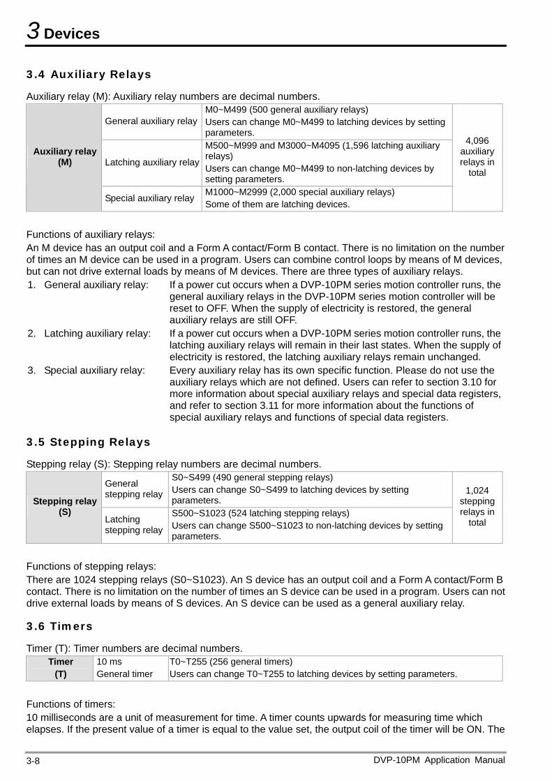
3 Devices
3.4 Auxiliary Relays
Auxiliary relay (M): Auxiliary relay numbers are decimal numbers.
General auxiliary relay M0~M499 (500 general auxiliary relays) Users can change M0~M499 to latching devices by setting parameters.
Latching auxiliary relay
M500~M999 and M3000~M4095 (1,596 latching auxiliary relays) Users can change M0~M499 to non-latching devices by setting parameters.
Auxiliary relay (M)
Special auxiliary relay M1000~M2999 (2,000 special auxiliary relays) Some of them are latching devices.
4,096 auxiliary relays in
total
Functions of auxiliary relays: An M device has an output coil and a Form A contact/Form B contact. There is no limitation on the number of times an M device can be used in a program. Users can combine control loops by means of M devices, but can not drive external loads by means of M devices. There are three types of auxiliary relays. 1. General auxiliary relay: If a power cut occurs when a DVP-10PM series motion controller runs, the
general auxiliary relays in the DVP-10PM series motion controller will be reset to OFF. When the supply of electricity is restored, the general auxiliary relays are still OFF.
2. Latching auxiliary relay: If a power cut occurs when a DVP-10PM series motion controller runs, the latching auxiliary relays will remain in their last states. When the supply of electricity is restored, the latching auxiliary relays remain unchanged.
3. Special auxiliary relay: Every auxiliary relay has its own specific function. Please do not use the auxiliary relays which are not defined. Users can refer to section 3.10 for more information about special auxiliary relays and special data registers, and refer to section 3.11 for more information about the functions of special auxiliary relays and functions of special data registers.
3.5 Stepping Relays
Stepping relay (S): Stepping relay numbers are decimal numbers.
General stepping relay
S0~S499 (490 general stepping relays) Users can change S0~S499 to latching devices by setting parameters. Stepping relay
(S) Latching stepping relay
S500~S1023 (524 latching stepping relays) Users can change S500~S1023 to non-latching devices by setting parameters.
1,024 stepping relays in
total
Functions of stepping relays: There are 1024 stepping relays (S0~S1023). An S device has an output coil and a Form A contact/Form B contact. There is no limitation on the number of times an S device can be used in a program. Users can not drive external loads by means of S devices. An S device can be used as a general auxiliary relay.
3.6 Timers
Timer (T): Timer numbers are decimal numbers. Timer
(T) 10 ms General timer
T0~T255 (256 general timers) Users can change T0~T255 to latching devices by setting parameters.
Functions of timers: 10 milliseconds are a unit of measurement for time. A timer counts upwards for measuring time which elapses. If the present value of a timer is equal to the value set, the output coil of the timer will be ON. The
DVP-10PM Application Manual 3-8
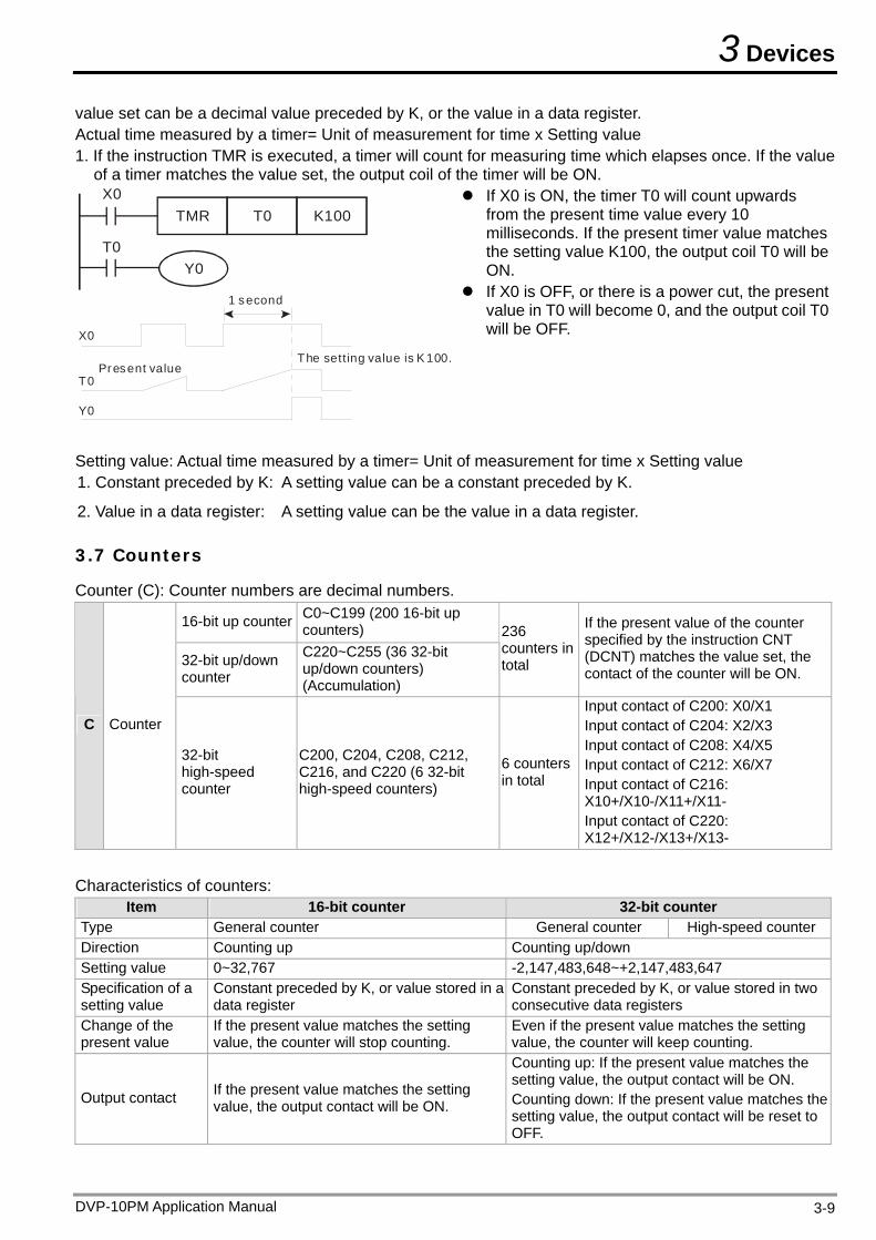
3 Devices
value set can be a decimal value preceded by K, or the value in a data register. Actual time measured by a timer= Unit of measurement for time x Setting value 1. If the instruction TMR is executed, a timer will count for measuring time which elapses once. If the value
of a timer matches the value set, the output coil of the timer will be ON.
T0Y0
X0TMR T0 K100
X0
T0
Y0
Present valueThe sett ing value is K 100.
1 second
If X0 is ON, the timer T0 will count upwards from the present time value every 10 milliseconds. If the present timer value matches the setting value K100, the output coil T0 will be ON.
If X0 is OFF, or there is a power cut, the present value in T0 will become 0, and the output coil T0 will be OFF.
Setting value: Actual time measured by a timer= Unit of measurement for time x Setting value 1. Constant preceded by K: A setting value can be a constant preceded by K.
2. Value in a data register: A setting value can be the value in a data register.
3.7 Counters
Counter (C): Counter numbers are decimal numbers.
16-bit up counter C0~C199 (200 16-bit up counters)
32-bit up/down counter
C220~C255 (36 32-bit up/down counters) (Accumulation)
236 counters in total
If the present value of the counter specified by the instruction CNT (DCNT) matches the value set, the contact of the counter will be ON.
C Counter
32-bit high-speed counter
C200, C204, C208, C212, C216, and C220 (6 32-bit high-speed counters)
6 counters in total
Input contact of C200: X0/X1 Input contact of C204: X2/X3 Input contact of C208: X4/X5 Input contact of C212: X6/X7 Input contact of C216: X10+/X10-/X11+/X11- Input contact of C220: X12+/X12-/X13+/X13-
Characteristics of counters:
Item 16-bit counter 32-bit counter Type General counter General counter High-speed counter Direction Counting up Counting up/down Setting value 0~32,767 -2,147,483,648~+2,147,483,647 Specification of a setting value
Constant preceded by K, or value stored in a data register
Constant preceded by K, or value stored in two consecutive data registers
Change of the present value
If the present value matches the setting value, the counter will stop counting.
Even if the present value matches the setting value, the counter will keep counting.
Output contact If the present value matches the setting value, the output contact will be ON.
Counting up: If the present value matches the setting value, the output contact will be ON. Counting down: If the present value matches the setting value, the output contact will be reset to OFF.
DVP-10PM Application Manual 3-9
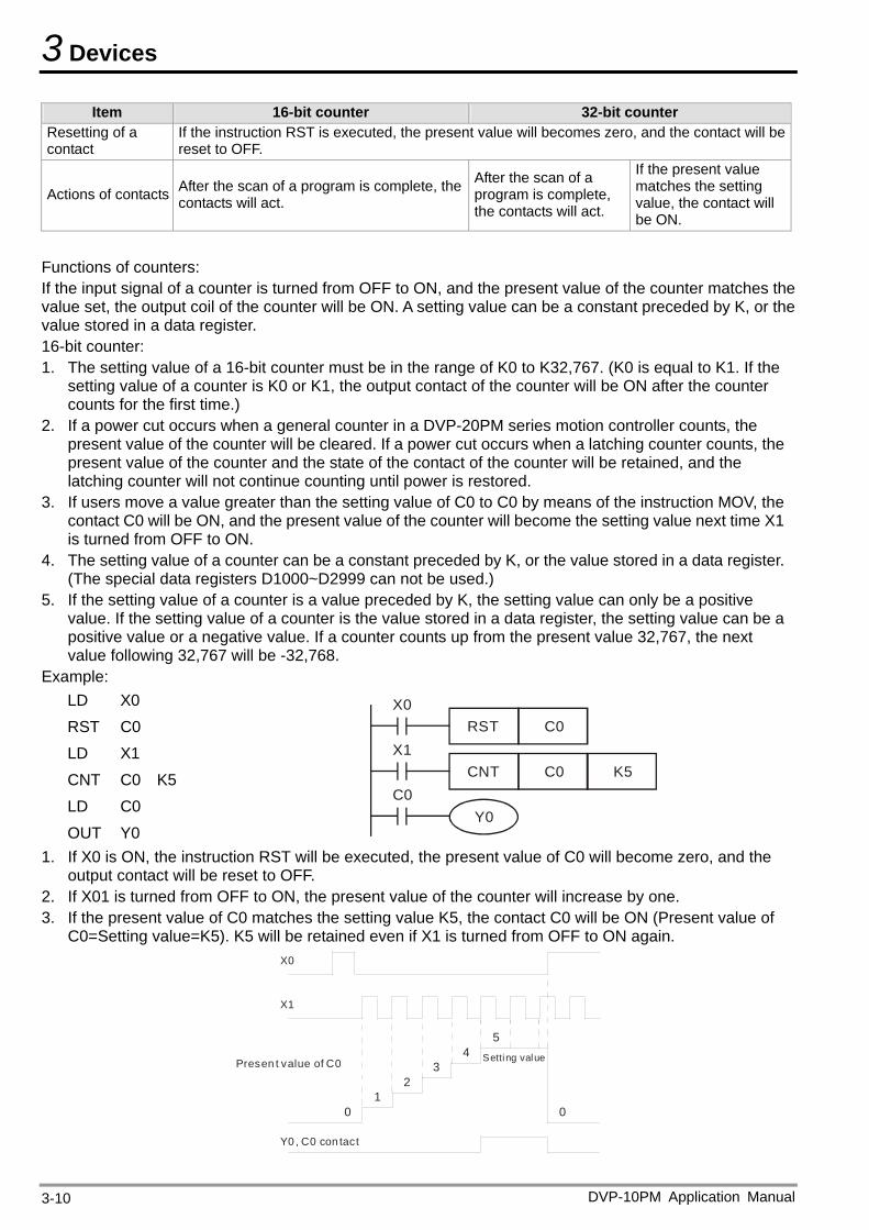
3 Devices
DVP-10PM Application Manual 3-10
Item 16-bit counter 32-bit counter Resetting of a contact
If the instruction RST is executed, the present value will becomes zero, and the contact will be reset to OFF.
Actions of contacts After the scan of a program is complete, the contacts will act.
After the scan of a program is complete, the contacts will act.
If the present value matches the setting value, the contact will be ON.
Functions of counters: If the input signal of a counter is turned from OFF to ON, and the present value of the counter matches the value set, the output coil of the counter will be ON. A setting value can be a constant preceded by K, or the value stored in a data register. 16-bit counter: 1. The setting value of a 16-bit counter must be in the range of K0 to K32,767. (K0 is equal to K1. If the
setting value of a counter is K0 or K1, the output contact of the counter will be ON after the counter counts for the first time.)
2. If a power cut occurs when a general counter in a DVP-20PM series motion controller counts, the present value of the counter will be cleared. If a power cut occurs when a latching counter counts, the present value of the counter and the state of the contact of the counter will be retained, and the latching counter will not continue counting until power is restored.
3. If users move a value greater than the setting value of C0 to C0 by means of the instruction MOV, the contact C0 will be ON, and the present value of the counter will become the setting value next time X1 is turned from OFF to ON.
4. The setting value of a counter can be a constant preceded by K, or the value stored in a data register. (The special data registers D1000~D2999 can not be used.)
5. If the setting value of a counter is a value preceded by K, the setting value can only be a positive value. If the setting value of a counter is the value stored in a data register, the setting value can be a positive value or a negative value. If a counter counts up from the present value 32,767, the next value following 32,767 will be -32,768.
Example: LD X0 RST C0 LD X1 CNT C0 K5 LD C0 OUT Y0
C0Y0
X1C0 K5CNT
X0C0RST
1. If X0 is ON, the instruction RST will be executed, the present value of C0 will become zero, and the
output contact will be reset to OFF. 2. If X01 is turned from OFF to ON, the present value of the counter will increase by one. 3. If the present value of C0 matches the setting value K5, the contact C0 will be ON (Present value of
C0=Setting value=K5). K5 will be retained even if X1 is turned from OFF to ON again. X0
X1
Y0 , C0 con tact
Presen t value of C0
01
23
45
Setting value
0
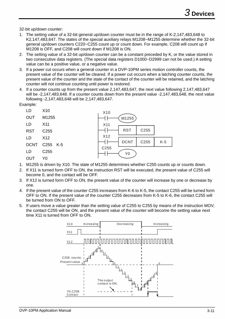
3 Devices
32-bit up/down counter: 1. The setting value of a 32-bit general up/down counter must be in the range of K-2,147,483,648 to
K2,147,483,647. The states of the special auxiliary relays M1208~M1255 determine whether the 32-bit general up/down counters C220~C255 count up or count down. For example, C208 will count up if M1208 is OFF, and C208 will count down if M1208 is ON.
2. The setting value of a 32-bit up/down counter can be a constant preceded by K, or the value stored in two consecutive data registers. (The special data registers D1000~D2999 can not be used.) A setting value can be a positive value, or a negative value.
3. If a power cut occurs when a general counter in a DVP-10PM series motion controller counts, the present value of the counter will be cleared. If a power cut occurs when a latching counter counts, the present value of the counter and the state of the contact of the counter will be retained, and the latching counter will not continue counting until power is restored.
4. If a counter counts up from the present value 2,147,483,647, the next value following 2,147,483,647 will be -2,147,483,648. If a counter counts down from the present value -2,147,483,648, the next value following -2,147,483,648 will be 2,147,483,647.
Example: LD X10 OUT M1255 LD X11 RST C255 LD X12 DCNT C255 K-5 LD C255 OUT Y0
C255Y0
X12C255 K-5DCNT
X11C255RST
X10M1255
1. M1255 is driven by X10. The state of M1255 determines whether C255 counts up or counts down. 2. If X11 is turned form OFF to ON, the instruction RST will be executed, the present value of C255 will
become 0, and the contact will be OFF. 3. If X12 is turned form OFF to ON, the present value of the counter will increase by one or decrease by
one. 4. If the present value of the counter C255 increases from K-6 to K-5, the contact C255 will be turned form
OFF to ON. If the present value of the counter C255 decreases from K-5 to K-6, the contact C255 will be turned from ON to OFF.
5. If users move a value greater than the setting value of C255 to C255 by means of the instruction MOV, the contact C255 will be ON, and the present value of the counter will become the setting value next time X11 is turned from OFF to ON.
X1 0
X11
X1 2
The o utpu t conta ct is ON.
Y0 ,C208 Contact
C208 cou nts.Presen t value
In crea sing In crea singDecreasing
01
23
45
43
21
0-1
-2-3
-4-5
-6-7
-8
0
-7-6
-5-4
-3
DVP-10PM Application Manual 3-11
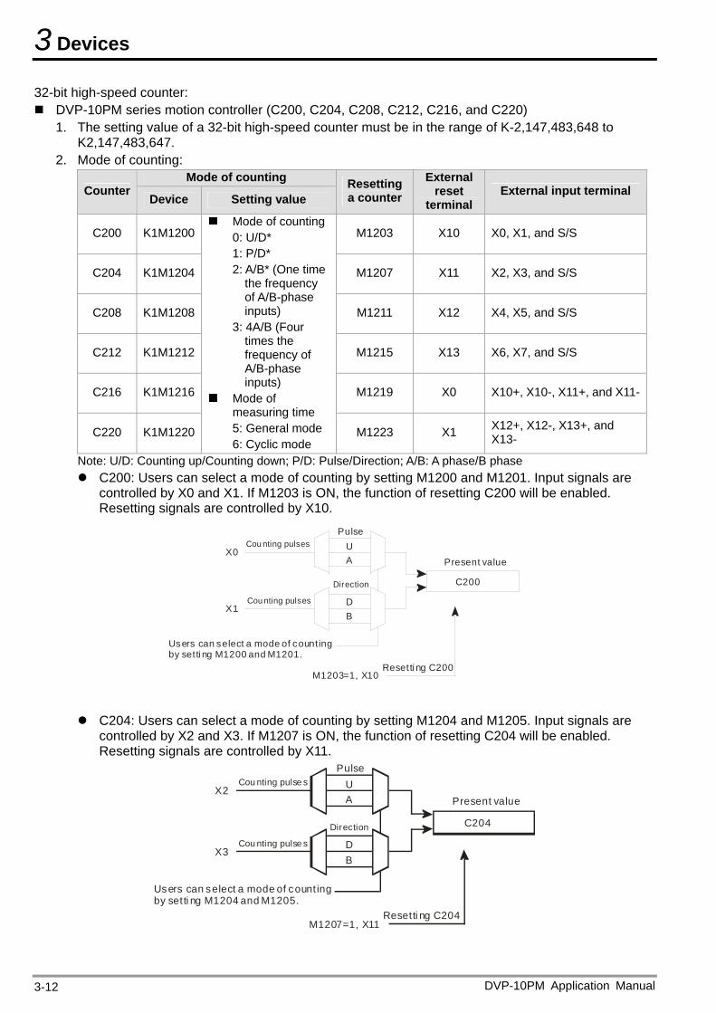
3 Devices
32-bit high-speed counter: DVP-10PM series motion controller (C200, C204, C208, C212, C216, and C220)
1. The setting value of a 32-bit high-speed counter must be in the range of K-2,147,483,648 to K2,147,483,647.
2. Mode of counting: Mode of counting
Counter Device Setting value
Resetting a counter
External reset
terminal External input terminal
C200 K1M1200 M1203 X10 X0, X1, and S/S
C204 K1M1204 M1207 X11 X2, X3, and S/S
C208 K1M1208 M1211 X12 X4, X5, and S/S
C212 K1M1212 M1215 X13 X6, X7, and S/S
C216 K1M1216 M1219 X0 X10+, X10-, X11+, and X11-
C220 K1M1220
Mode of counting 0: U/D* 1: P/D* 2: A/B* (One time
the frequency of A/B-phase inputs)
3: 4A/B (Four times the frequency of A/B-phase inputs)
Mode of measuring time 5: General mode 6: Cyclic mode
M1223 X1 X12+, X12-, X13+, and X13-
Note: U/D: Counting up/Counting down; P/D: Pulse/Direction; A/B: A phase/B phase C200: Users can select a mode of counting by setting M1200 and M1201. Input signals are
controlled by X0 and X1. If M1203 is ON, the function of resetting C200 will be enabled. Resetting signals are controlled by X10.
Cou nting pulses
Cou nting pulses
Direction
Present value
Users can select a mode of counting by setti ng M1200 and M1201.
C200
Resetti ng C200
PulseUA
BD
X1
X0
M1203=1, X10
C204: Users can select a mode of counting by setting M1204 and M1205. Input signals are
controlled by X2 and X3. If M1207 is ON, the function of resetting C204 will be enabled. Resetting signals are controlled by X11.
C204
Resetti ng C204
Cou nting pulse s
Cou nting pulse sPulse
UA
B
Direction
Present value
D
Users can select a mode of count ing by setti ng M1204 and M1205.
X3
X2
M1207=1, X11
DVP-10PM Application Manual 3-12
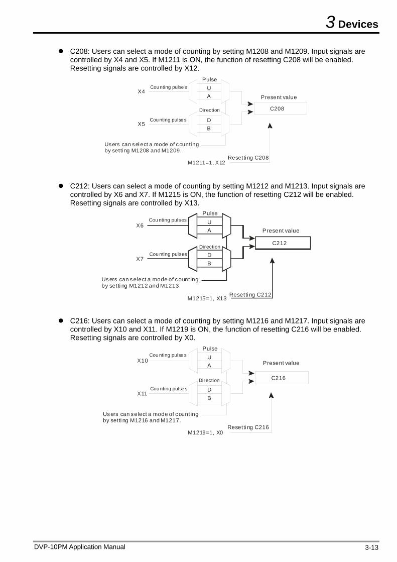
3 Devices
C208: Users can select a mode of counting by setting M1208 and M1209. Input signals are controlled by X4 and X5. If M1211 is ON, the function of resetting C208 will be enabled. Resetting signals are controlled by X12.
Cou nting pulse s
Cou nting pulse s
Direction
Present value
Users can sel ect a mode of counting by set ti ng M1208 and M1209.
C208
Resetti ng C208
PulseUA
BD
X5
X4
M1211=1, X12
C212: Users can select a mode of counting by setting M1212 and M1213. Input signals are controlled by X6 and X7. If M1215 is ON, the function of resetting C212 will be enabled. Resetting signals are controlled by X13.
DirectionCou nting pulses
Cou nting pulses
Present value
Users can select a mode of count ing by setti ng M1212 and M1213.
C212
Resetti ng C212
PulseUA
BD
X7
X6
M1215=1, X13
C216: Users can select a mode of counting by setting M1216 and M1217. Input signals are controlled by X10 and X11. If M1219 is ON, the function of resetting C216 will be enabled. Resetting signals are controlled by X0.
Direction
Cou nting pulse s
Cou nting pulse s
Present value
Users can select a mode of count ing by setti ng M1216 and M1217.
C216
Resetti ng C216
PulseUA
BD
X11
X10
M1219=1, X0
DVP-10PM Application Manual 3-13
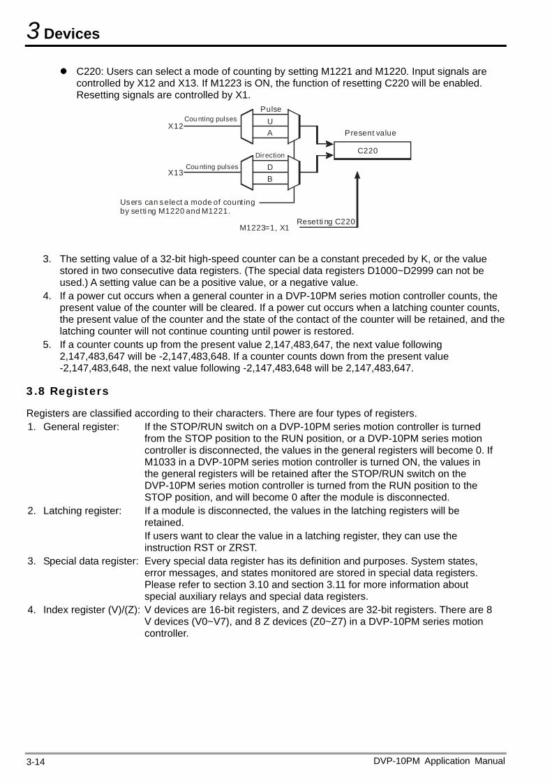
3 Devices
C220: Users can select a mode of counting by setting M1221 and M1220. Input signals are controlled by X12 and X13. If M1223 is ON, the function of resetting C220 will be enabled. Resetting signals are controlled by X1.
Cou nting pulses
Cou nting pulses
Present value
Users can select a mode of count ing by setti ng M1220 and M1221.
C220
Resetti ng C220
PulseUA
B
Direction
DX13
X12
M1223=1, X1
3. The setting value of a 32-bit high-speed counter can be a constant preceded by K, or the value stored in two consecutive data registers. (The special data registers D1000~D2999 can not be used.) A setting value can be a positive value, or a negative value.
4. If a power cut occurs when a general counter in a DVP-10PM series motion controller counts, the present value of the counter will be cleared. If a power cut occurs when a latching counter counts, the present value of the counter and the state of the contact of the counter will be retained, and the latching counter will not continue counting until power is restored.
5. If a counter counts up from the present value 2,147,483,647, the next value following 2,147,483,647 will be -2,147,483,648. If a counter counts down from the present value -2,147,483,648, the next value following -2,147,483,648 will be 2,147,483,647.
3.8 Registers
Registers are classified according to their characters. There are four types of registers. 1. General register: If the STOP/RUN switch on a DVP-10PM series motion controller is turned
from the STOP position to the RUN position, or a DVP-10PM series motion controller is disconnected, the values in the general registers will become 0. If M1033 in a DVP-10PM series motion controller is turned ON, the values in the general registers will be retained after the STOP/RUN switch on the DVP-10PM series motion controller is turned from the RUN position to the STOP position, and will become 0 after the module is disconnected.
2. Latching register: If a module is disconnected, the values in the latching registers will be retained. If users want to clear the value in a latching register, they can use the instruction RST or ZRST.
3. Special data register: Every special data register has its definition and purposes. System states, error messages, and states monitored are stored in special data registers. Please refer to section 3.10 and section 3.11 for more information about special auxiliary relays and special data registers.
4. Index register (V)/(Z): V devices are 16-bit registers, and Z devices are 32-bit registers. There are 8 V devices (V0~V7), and 8 Z devices (Z0~Z7) in a DVP-10PM series motion controller.
DVP-10PM Application Manual 3-14
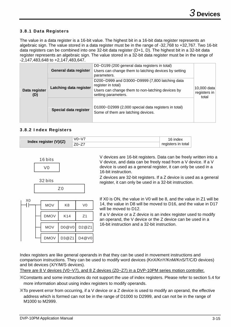
3 Devices
3.8.1 Data Registers
The value in a data register is a 16-bit value. The highest bit in a 16-bit data register represents an algebraic sign. The value stored in a data register must be in the range of -32,768 to +32,767. Two 16-bit data registers can be combined into one 32-bit data register (D+1, D). The highest bit in a 32-bit data register represents an algebraic sign. The value stored in a 32-bit data register must be in the range of -2,147,483,648 to +2,147,483,647.
General data register D0~D199 (200 general data registers in total) Users can change them to latching devices by setting parameters.
Latching data register
D200~D999 and D3000~D9999 (7,800 latching data register in total) Users can change them to non-latching devices by setting parameters.
Data register (D)
Special data register D1000~D2999 (2,000 special data registers in total) Some of them are latching devices.
10,000 data registers in
total
3.8.2 Index Registers
V0~V7 Index register (V)/(Z) Z0~Z7
16 index registers in total
V0
Z0
16 bits
32 bits
V devices are 16-bit registers. Data can be freely written into a V device, and data can be freely read from a V device. If a V device is used as a general register, it can only be used in a 16-bit instruction. Z devices are 32-bit registers. If a Z device is used as a general register, it can only be used in a 32-bit instruction.
K14 Z1
X0K8 V0MOV
DMOV
D3@Z1 D4@V0
D0@V0 D2@Z1MOV
DMOV
If X0 is ON, the value in V0 will be 8, and the value in Z1 will be 14, the value in D8 will be moved to D16, and the value in D17 will be moved to D12. If a V device or a Z device is an index register used to modify an operand, the V device or the Z device can be used in a 16-bit instruction and a 32-bit instruction.
Index registers are like general operands in that they can be used in movement instructions and comparison instructions. They can be used to modify word devices (KnX/KnY/KnM/KnS/T/C/D devices) and bit devices (X/Y/M/S devices). There are 8 V devices (V0~V7), and 8 Z devices (Z0~Z7) in a DVP-10PM series motion controller.
※Constants and some instructions do not support the use of index registers. Please refer to section 5.4 for more information about using index registers to modify operands.
※To prevent error from occurring, if a V device or a Z device is used to modify an operand, the effective address which is formed can not be in the range of D1000 to D2999, and can not be in the range of M1000 to M2999.
DVP-10PM Application Manual 3-15
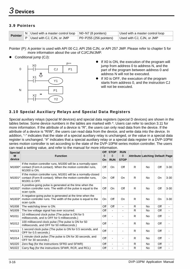
3 Devices
3.9 Pointers
N Used with a master control loop N0~N7 (8 poniters) Used with a master control loop Pointer
P Used with CJ, CJN, or JMP P0~P255 (256 pointers) Used with CJ, CJN, or JMP
Pointer (P): A pointer is used with API 00 CJ, API 256 CJN, or API 257 JMP. Please refer to chapter 5 for
more information about the use of CJ/CJN/JMP. Conditional jump (CJ):
X2Y2
X1
P1CJX0
Y1
P**
0
N P1
If X0 is ON, the execution of the program will jump from address 0 to address N, and the part of the program between address 0 and address N will not be executed.
If X0 is OFF, the execution of the program starts from address 0, and the instruction CJ will not be executed.
3.10 Special Auxiliary Relays and Special Data Registers
Special auxiliary relays (special M devices) and special data registers (special D devices) are shown in the tables below. Some device numbers in the tables are marked with *. Users can refer to section 3.11 for more information. If the attribute of a device is “R”, the users can only read data from the device. If the attribute of a device is “R/W”, the users can read data from the device, and write data into the device. In addition, “-” indicates that the state of a special auxiliary relay is unchanged, or the value in a special data register is unchanged. “#” indicates that a special auxiliary relay or a special data register in a DVP-10PM series motion controller is set according to the state of the DVP-10PM series motion controller. The users can read a setting value, and refer to the manual for more information. Special
M device
Function Off
On
STOP
RUN
RUN
STOPAttribute Latching Default Page
M1000* If the motion controller runs, M1000 will be a normally-open contact (Form A contact). When the motion controller runs, M1000 is ON.
Off On Off R No Off 3-30
M1001* If the motion controller runs, M1001 will be a normally-closed contact (Form B contact). When the motion controller runs, M1001 is OFF.
On Off On R No On 3-30
M1002* A positive-going pulse is generated at the time when the motion controller runs. The width of the pulse is equal to the scan cycle.
Off On Off R No Off 3-30
M1003* A negative-going pulse is generated at the time when the motion controller runs. The width of the pulse is equal to the scan cycle.
On Off On R No On 3-30
M1008 The watchdog timer is ON. Off Off - R No Off - M1009 The low voltage signal has ever occurred. Off - - R No Off -
M1011 10 millisecond clock pulse (The pulse is ON for 5 milliseconds, and is OFF for 5 milliseconds.) Off - - R No Off -
M1012 100 millisecond clock pulse (The pulse is ON for 50 milliseconds, and OFF for 50 milliseconds.) Off - - R No Off -
M1013 1 second clock pulse (The pulse is ON for 0.5 seconds, and OFF for 0.5 seconds.) Off - - R No Off -
M1014 1 minute clock pulse (The pulse is ON for 30 seconds, and OFF for 30 seconds.) Off - - R No Off -
M1020 Zero flag (for the instructions SFRD and SFWR) Off - - R No Off - M1022 Carry flag (for the instructions SFWR, RCR, and RCL) Off - - R No Off -
DVP-10PM Application Manual 3-16
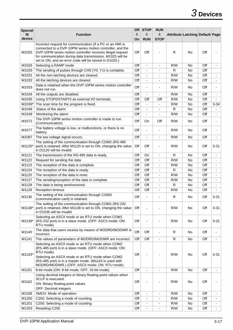
3 Devices
DVP-10PM Application Manual 3-17
Special M
device Function
Off
On
STOP
RUN
RUN
STOPAttribute Latching Default Page
M1025
Incorrect request for communication (If a PC or an HMI is connected to a DVP-10PM series motion controller, and the DVP-10PM series motion controller receives illegal request for communication during data transmission, M1025 will be set to ON, and an error code will be stored in D1025.)
Off Off - R No Off -
M1026 Selecting a RAMP mode Off - - R/W No Off - M1029 The sending of pulses through CH0 (Y0, Y1) is complete. Off - - R No Off M1031 All the non-latching devices are cleared. Off - - R/W No Off - M1032 All the latching devices are cleared. Off - - R/W No Off -
M1033 Data is retained when the DVP-10PM series motion controller does not run. Off - - R/W No Off -
M1034 All the outputs are disabled. Off - - R/W No Off - M1035 Using STOP0/START0 as external I/O terminals. Off Off Off R/W No Off - M1039* The scan time for the program is fixed. Off - - R/W No Off 3-34M1048 Status of the alarm Off - - R No Off - M1049 Monitoring the alarm Off - - R/W No Off -
M1072 The DVP-10PM series motion controller is made to run. (Communication) Off On Off R/W No Off -
M1077 The battery voltage is low, or malfunctions, or there is no battery. Off - - R/W No Off -
M1087 The low voltage signal occurs. Off - - R/W No Off -
M1120* The setting of the communication through COM2 (RS-485 port) is retained. After M1120 is set to ON, changing the value in D1120 will be invalid.
Off Off - R/W No Off 3-31
M1121 The transmission of the RS-485 data is ready. Off On - R No Off - M1122 Request for sending the data Off Off - R/W No Off - M1123 The reception of the data is complete. Off Off - R/W No Off - M1124 The reception of the data is ready. Off Off - R No Off - M1125 The reception of the data is reset. Off Off - R/W No Off - M1127 The sending/reception of the data is complete. Off Off - R/W No Off - M1128 The data is being sent/received. Off Off - R No Off - M1129 Reception timeout Off Off - R/W No Off -
M1136 The setting of the communication through COM3 (communication card) is retained. Off - - R No Off 3-31
M1138* The setting of the communication through COM1 (RS-232 port) is retained. After M1138 is set to ON, changing the value in D1036 will be invalid.
Off - - R/W No Off 3-31
M1139* Selecting an ASCII mode or an RTU mode when COM1 (RS-232 port) is in a slave mode. (OFF: ASCII mode; ON: RTU mode)
Off - - R/W No Off 3-31
M1140 The data that users receive by means of MODRD/MODWR is incorrect. Off Off - R No Off -
M1141 The values of parameters of MODRD/MODWR are incorrect. Off Off - R No Off -
M1143*
Selecting an ASCII mode or an RTU mode when COM2 (RS-485 port) is in a slave mode. (OFF: ASCII mode; ON: RTU mode) Selecting an ASCII mode or an RTU mode when COM2 (RS-485 port) is in a master mode. (M1143 is used with MODRD/MODWR.) (OFF: ASCII mode; ON: RTU mode)
Off - - R/W No Off 3-31
M1161 8-bit mode (ON: 8-bit mode; OFF: 16-bit mode) Off - - R/W No Off -
M1162
Using decimal integers or binary floating-point values when SCLP is executed. ON: Binary floating-point values OFF: Decimal integers
Off - - R/W No Off -
M1168 SMOV: Mode of operation Off - - R/W No Off - M1200 C200: Selecting a mode of counting Off - - R/W No Off - M1201 C200: Selecting a mode of counting Off - - R/W No Off - M1203 Resetting C200 Off - - R/W No Off -
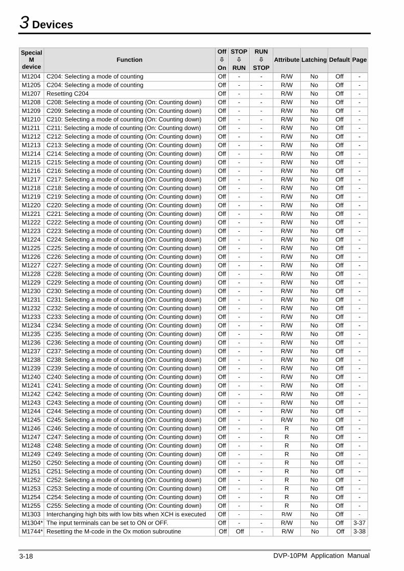
3 Devices
DVP-10PM Application Manual 3-18
Special M
device Function
Off
On
STOP
RUN
RUN
STOPAttribute Latching Default Page
M1204 C204: Selecting a mode of counting Off - - R/W No Off - M1205 C204: Selecting a mode of counting Off - - R/W No Off - M1207 Resetting C204 Off - - R/W No Off - M1208 C208: Selecting a mode of counting (On: Counting down) Off - - R/W No Off - M1209 C209: Selecting a mode of counting (On: Counting down) Off - - R/W No Off - M1210 C210: Selecting a mode of counting (On: Counting down) Off - - R/W No Off - M1211 C211: Selecting a mode of counting (On: Counting down) Off - - R/W No Off - M1212 C212: Selecting a mode of counting (On: Counting down) Off - - R/W No Off - M1213 C213: Selecting a mode of counting (On: Counting down) Off - - R/W No Off - M1214 C214: Selecting a mode of counting (On: Counting down) Off - - R/W No Off - M1215 C215: Selecting a mode of counting (On: Counting down) Off - - R/W No Off - M1216 C216: Selecting a mode of counting (On: Counting down) Off - - R/W No Off - M1217 C217: Selecting a mode of counting (On: Counting down) Off - - R/W No Off - M1218 C218: Selecting a mode of counting (On: Counting down) Off - - R/W No Off - M1219 C219: Selecting a mode of counting (On: Counting down) Off - - R/W No Off - M1220 C220: Selecting a mode of counting (On: Counting down) Off - - R/W No Off - M1221 C221: Selecting a mode of counting (On: Counting down) Off - - R/W No Off - M1222 C222: Selecting a mode of counting (On: Counting down) Off - - R/W No Off - M1223 C223: Selecting a mode of counting (On: Counting down) Off - - R/W No Off - M1224 C224: Selecting a mode of counting (On: Counting down) Off - - R/W No Off - M1225 C225: Selecting a mode of counting (On: Counting down) Off - - R/W No Off - M1226 C226: Selecting a mode of counting (On: Counting down) Off - - R/W No Off - M1227 C227: Selecting a mode of counting (On: Counting down) Off - - R/W No Off - M1228 C228: Selecting a mode of counting (On: Counting down) Off - - R/W No Off - M1229 C229: Selecting a mode of counting (On: Counting down) Off - - R/W No Off - M1230 C230: Selecting a mode of counting (On: Counting down) Off - - R/W No Off - M1231 C231: Selecting a mode of counting (On: Counting down) Off - - R/W No Off - M1232 C232: Selecting a mode of counting (On: Counting down) Off - - R/W No Off - M1233 C233: Selecting a mode of counting (On: Counting down) Off - - R/W No Off - M1234 C234: Selecting a mode of counting (On: Counting down) Off - - R/W No Off - M1235 C235: Selecting a mode of counting (On: Counting down) Off - - R/W No Off - M1236 C236: Selecting a mode of counting (On: Counting down) Off - - R/W No Off - M1237 C237: Selecting a mode of counting (On: Counting down) Off - - R/W No Off - M1238 C238: Selecting a mode of counting (On: Counting down) Off - - R/W No Off - M1239 C239: Selecting a mode of counting (On: Counting down) Off - - R/W No Off - M1240 C240: Selecting a mode of counting (On: Counting down) Off - - R/W No Off - M1241 C241: Selecting a mode of counting (On: Counting down) Off - - R/W No Off - M1242 C242: Selecting a mode of counting (On: Counting down) Off - - R/W No Off - M1243 C243: Selecting a mode of counting (On: Counting down) Off - - R/W No Off - M1244 C244: Selecting a mode of counting (On: Counting down) Off - - R/W No Off - M1245 C245: Selecting a mode of counting (On: Counting down) Off - - R/W No Off - M1246 C246: Selecting a mode of counting (On: Counting down) Off - - R No Off - M1247 C247: Selecting a mode of counting (On: Counting down) Off - - R No Off - M1248 C248: Selecting a mode of counting (On: Counting down) Off - - R No Off - M1249 C249: Selecting a mode of counting (On: Counting down) Off - - R No Off - M1250 C250: Selecting a mode of counting (On: Counting down) Off - - R No Off - M1251 C251: Selecting a mode of counting (On: Counting down) Off - - R No Off - M1252 C252: Selecting a mode of counting (On: Counting down) Off - - R No Off - M1253 C253: Selecting a mode of counting (On: Counting down) Off - - R No Off - M1254 C254: Selecting a mode of counting (On: Counting down) Off - - R No Off - M1255 C255: Selecting a mode of counting (On: Counting down) Off - - R No Off - M1303 Interchanging high bits with low bits when XCH is executed Off - - R/W No Off - M1304* The input terminals can be set to ON or OFF. Off - - R/W No Off 3-37M1744* Resetting the M-code in the Ox motion subroutine Off Off - R/W No Off 3-38
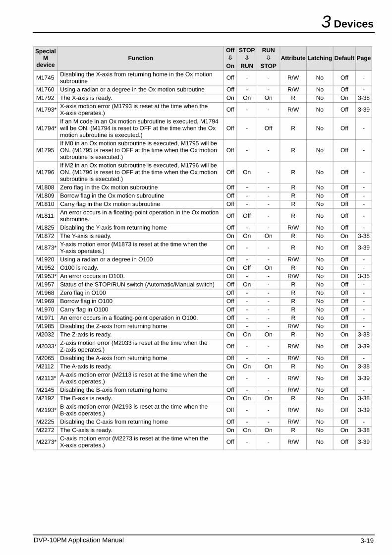
3 Devices
Special M
device Function
Off
On
STOP
RUN
RUN
STOPAttribute Latching Default Page
M1745 Disabling the X-axis from returning home in the Ox motion subroutine Off - - R/W No Off -
M1760 Using a radian or a degree in the Ox motion subroutine Off - - R/W No Off - M1792 The X-axis is ready. On On On R No On 3-38
M1793* X-axis motion error (M1793 is reset at the time when the X-axis operates.) Off - - R/W No Off 3-39
M1794* If an M code in an Ox motion subroutine is executed, M1794 will be ON. (M1794 is reset to OFF at the time when the Ox motion subroutine is executed.)
Off - Off R No Off -
M1795 If M0 in an Ox motion subroutine is executed, M1795 will be ON. (M1795 is reset to OFF at the time when the Ox motion subroutine is executed.)
Off - - R No Off -
M1796 If M2 in an Ox motion subroutine is executed, M1796 will be ON. (M1796 is reset to OFF at the time when the Ox motion subroutine is executed.)
Off On - R No Off -
M1808 Zero flag in the Ox motion subroutine Off - - R No Off - M1809 Borrow flag in the Ox motion subroutine Off - - R No Off - M1810 Carry flag in the Ox motion subroutine Off - - R No Off -
M1811 An error occurs in a floating-point operation in the Ox motion subroutine. Off Off - R No Off -
M1825 Disabling the Y-axis from returning home Off - - R/W No Off - M1872 The Y-axis is ready. On On On R No On 3-38
M1873* Y-axis motion error (M1873 is reset at the time when the Y-axis operates.) Off - - R No Off 3-39
M1920 Using a radian or a degree in O100 Off - - R/W No Off - M1952 O100 is ready. On Off On R No On - M1953* An error occurs in O100. Off - - R/W No Off 3-35M1957 Status of the STOP/RUN switch (Automatic/Manual switch) Off On - R No Off - M1968 Zero flag in O100 Off - - R No Off - M1969 Borrow flag in O100 Off - - R No Off - M1970 Carry flag in O100 Off - - R No Off - M1971 An error occurs in a floating-point operation in O100. Off - - R No Off - M1985 Disabling the Z-axis from returning home Off - - R/W No Off - M2032 The Z-axis is ready. On On On R No On 3-38
M2033* Z-axis motion error (M2033 is reset at the time when the Z-axis operates.) Off - - R/W No Off 3-39
M2065 Disabling the A-axis from returning home Off - - R/W No Off - M2112 The A-axis is ready. On On On R No On 3-38
M2113* A-axis motion error (M2113 is reset at the time when the A-axis operates.) Off - - R/W No Off 3-39
M2145 Disabling the B-axis from returning home Off - - R/W No Off - M2192 The B-axis is ready. On On On R No On 3-38
M2193* B-axis motion error (M2193 is reset at the time when the B-axis operates.) Off - - R/W No Off 3-39
M2225 Disabling the C-axis from returning home Off - - R/W No Off - M2272 The C-axis is ready. On On On R No On 3-38
M2273* C-axis motion error (M2273 is reset at the time when the X-axis operates.) Off - - R/W No Off 3-39
DVP-10PM Application Manual 3-19
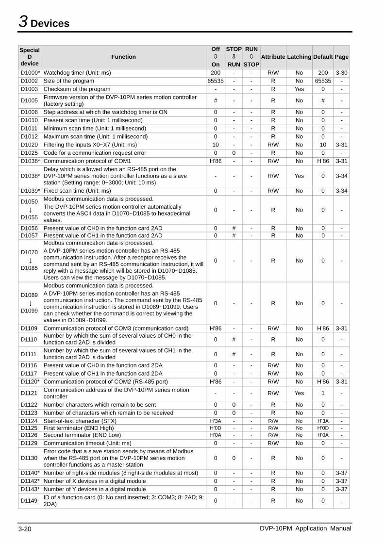
3 Devices
Special D
device Function
Off
On
STOP
RUN
RUN
STOPAttribute Latching Default Page
D1000* Watchdog timer (Unit: ms) 200 - - R/W No 200 3-30D1002 Size of the program 65535 - - R No 65535 - D1003 Checksum of the program - - - R Yes 0 -
D1005 Firmware version of the DVP-10PM series motion controller (factory setting) # - - R No # -
D1008 Step address at which the watchdog timer is ON 0 - - R No 0 - D1010 Present scan time (Unit: 1 millisecond) 0 - - R No 0 - D1011 Minimum scan time (Unit: 1 millisecond) 0 - - R No 0 - D1012 Maximum scan time (Unit: 1 millisecond) 0 - - R No 0 - D1020 Filtering the inputs X0~X7 (Unit: ms) 10 - - R/W No 10 3-31D1025 Code for a communication request error 0 0 - R No 0 - D1036* Communication protocol of COM1 H’86 - - R/W No H’86 3-31
D1038* Delay which is allowed when an RS-485 port on the DVP-10PM series motion controller functions as a slave station (Setting range: 0~3000; Unit: 10 ms)
- - - R/W Yes 0 3-34
D1039* Fixed scan time (Unit: ms) 0 - - R/W No 0 3-34
D1050 ↓
D1055
Modbus communication data is processed. The DVP-10PM series motion controller automatically converts the ASCII data in D1070~D1085 to hexadecimal values.
0 - - R No 0 -
D1056 Present value of CH0 in the function card 2AD 0 # - R No 0 - D1057 Present value of CH1 in the function card 2AD 0 # - R No 0 -
D1070 ↓
D1085
Modbus communication data is processed. A DVP-10PM series motion controller has an RS-485 communication instruction. After a receptor receives the command sent by an RS-485 communication instruction, it will reply with a message which will be stored in D1070~D1085. Users can view the message by D1070~D1085.
0 - - R No 0 -
D1089 ↓
D1099
Modbus communication data is processed. A DVP-10PM series motion controller has an RS-485 communication instruction. The command sent by the RS-485 communication instruction is stored in D1089~D1099. Users can check whether the command is correct by viewing the values in D1089~D1099.
0 - - R No 0 -
D1109 Communication protocol of COM3 (communication card) H’86 - - R/W No H’86 3-31
D1110 Number by which the sum of several values of CH0 in the function card 2AD is divided 0 # - R No 0 -
D1111 Number by which the sum of several values of CH1 in the function card 2AD is divided 0 # - R No 0 -
D1116 Present value of CH0 in the function card 2DA 0 - - R/W No 0 - D1117 Present value of CH1 in the function card 2DA 0 - - R/W No 0 - D1120* Communication protocol of COM2 (RS-485 port) H’86 - - R/W No H’86 3-31
D1121 Communication address of the DVP-10PM series motion controller - - - R/W Yes 1 -
D1122 Number characters which remain to be sent 0 0 - R No 0 - D1123 Number of characters which remain to be received 0 0 - R No 0 - D1124 Start-of-text character (STX) H’3A - - R/W No H’3A - D1125 First terminator (END High) H’0D - - R/W No H’0D - D1126 Second terminator (END Low) H’0A - - R/W No H’0A - D1129 Communication timeout (Unit: ms) 0 - - R/W No 0 -
D1130 Error code that a slave station sends by means of Modbus when the RS-485 port on the DVP-10PM series motion controller functions as a master station
0 0 - R No 0 -
D1140* Number of right-side modules (8 right-side modules at most) 0 - - R No 0 3-37D1142* Number of X devices in a digital module 0 - - R No 0 3-37D1143* Number of Y devices in a digital module 0 - - R No 0 3-37
D1149 ID of a function card (0: No card inserted; 3: COM3; 8: 2AD; 9: 2DA) 0 - - R No 0 -
DVP-10PM Application Manual 3-20
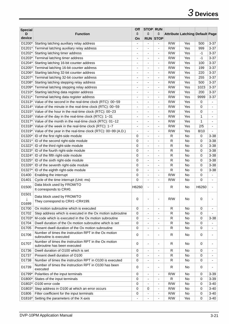
3 Devices
DVP-10PM Application Manual 3-21
Special D
device Function
Off
On
STOP
RUN
RUN
STOP Attribute Latching Default Page
D1200* Starting latching auxiliary relay address - - - R/W Yes 500 3-37D1201* Terminal latching auxiliary relay address - - - R/W Yes 999 3-37D1202* Starting latching timer address - - - R/W Yes -1 3-37D1203* Terminal latching timer address - - - R/W Yes -1 3-37D1204* Starting latching 16-bit counter address - - - R/W Yes 100 3-37D1205* Terminal latching 16-bit counter address - - - R/W Yes 199 3-37D1206* Starting latching 32-bit counter address - - - R/W Yes 220 3-37D1207* Terminal latching 32-bit counter address - - - R/W Yes 255 3-37D1208* Starting latching stepping relay address - - - R/W Yes 500 3-37D1209* Terminal latching stepping relay address - - - R/W Yes 1023 3-37D1210* Starting latching data register address - - - R/W Yes 200 3-37D1211* Terminal latching data register address - - - R/W Yes 9999 3-37D1313* Value of the second in the real-time clock (RTC): 00~59 - - - R/W Yes 0 - D1314* Value of the minute in the real-time clock (RTC): 00~59 - - - R/W Yes 0 - D1315* Value of the hour in the real-time clock (RTC): 00~23 - - - R/W Yes 0 - D1316* Value of the day in the real-time clock (RTC): 1~31 - - - R/W Yes 1 - D1317* Value of the month in the real-time clock (RTC): 01~12 - - - R/W Yes 1 - D1318* Value of the week in the real-time clock (RTC): 1~7 - - - R/W Yes 2/5 - D1319* Value of the year in the real-time clock (RTC): 00~99 (A.D.) - - - R/W Yes 8/10 - D1320* ID of the first right-side module 0 - - R No 0 3-38D1321* ID of the second right-side module 0 - - R No 0 3-38D1322* ID of the third right-side module 0 - - R No 0 3-38D1323* ID of the fourth right-side module 0 - - R No 0 3-38D1324* ID of the fifth right-side module 0 - - R No 0 3-38D1325* ID of the sixth right-side module 0 - - R No 0 3-38D1326* ID of the seventh right-side module 0 - - R No 0 3-38D1327* ID of the eighth right-side module 0 - - R No 0 3-38D1400 Enabling the interrupt 0 - - R/W No 0 - D1401 Cycle of the time interrupt (Unit: ms) 0 - - R/W No 0 -
D1500 Data block used by FROM/TO It corresponds to CR#0.
H6260 - - R No H6260 -
D1501 ↓
D1699
Data block used by FROM/TO They correspond to CR#1~CR#199.
0 - - R/W No 0 -
D1700 Ox motion subroutine which is executed 0 - - R No 0 - D1702 Step address which is executed in the Ox motion subroutine 0 - - R No 0 - D1703* M-code which is executed in the Ox motion subroutine 0 - - R No 0 3-38D1704 Dwell duration of the Ox motion subroutine which is set 0 - - R No 0 - D1705 Present dwell duration of the Ox motion subroutine 0 - - R No 0 -
D1706 Number of times the instruction RPT in the Ox motion subroutine is executed 0 - - R No 0 -
D1707 Number of times the instruction RPT in the Ox motion subroutine has been executed 0 - - R No 0 -
D1736 Dwell duration of O100 which is set 0 - - R No 0 - D1737 Present dwell duration of O100 0 - - R No 0 - D1738 Number of times the instruction RPT in O100 is executed 0 - - R No 0 -
D1739 Number of times the instruction RPT in O100 has been executed 0 - - R No 0 -
D1799* Polarities of the input terminals 0 - - R/W No 0 3-39D1800* States of the input terminals 0 - - R No 0 3-39D1802* O100 error code 0 - - R/W No 0 3-40D1803* Step address in O100 at which an error occurs 0 0 - R/W No 0 3-40D1806 Filter coefficient for the input terminals 0 - - R/W No 0 3-40D1816* Setting the parameters of the X-axis - - - R/W Yes 0 3-40
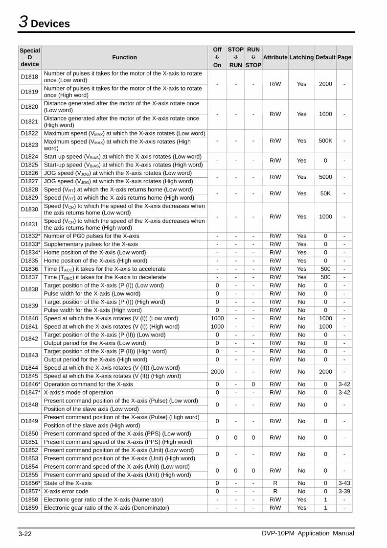
3 Devices
DVP-10PM Application Manual 3-22
Special D
device Function
Off
On
STOP
RUN
RUN
STOPAttribute Latching Default Page
D1818 Number of pulses it takes for the motor of the X-axis to rotate once (Low word)
D1819 Number of pulses it takes for the motor of the X-axis to rotate once (High word)
- - - R/W Yes 2000 -
D1820 Distance generated after the motor of the X-axis rotate once (Low word)
D1821 Distance generated after the motor of the X-axis rotate once (High word)
- - - R/W Yes 1000 -
D1822 Maximum speed (VMAX) at which the X-axis rotates (Low word)
D1823 Maximum speed (VMAX) at which the X-axis rotates (High word)
- - - R/W Yes 500K -
D1824 Start-up speed (VBIAS) at which the X-axis rotates (Low word) D1825 Start-up speed (VBIAS) at which the X-axis rotates (High word)
- - - R/W Yes 0 -
D1826 JOG speed (VJOG) at which the X-axis rotates (Low word) D1827 JOG speed (VJOG) at which the X-axis rotates (High word)
- - - R/W Yes 5000 -
D1828 Speed (VRT) at which the X-axis returns home (Low word) D1829 Speed (VRT) at which the X-axis returns home (High word)
- - - R/W Yes 50K -
D1830 Speed (VCR) to which the speed of the X-axis decreases when the axis returns home (Low word)
D1831 Speed (VCR) to which the speed of the X-axis decreases when the axis returns home (High word)
- - - R/W Yes 1000 -
D1832* Number of PG0 pulses for the X-axis - - - R/W Yes 0 - D1833* Supplementary pulses for the X-axis - - - R/W Yes 0 - D1834* Home position of the X-axis (Low word) - - - R/W Yes 0 - D1835 Home position of the X-axis (High word) - - - R/W Yes 0 - D1836 Time (TACC) it takes for the X-axis to accelerate - - - R/W Yes 500 - D1837 Time (TDEC) it takes for the X-axis to decelerate - - - R/W Yes 500 -
Target position of the X-axis (P (I)) (Low word) 0 - - R/W No 0 - D1838
Pulse width for the X-axis (Low word) 0 - - R/W No 0 - Target position of the X-axis (P (I)) (High word) 0 - - R/W No 0 -
D1839 Pulse width for the X-axis (High word) 0 - - R/W No 0 -
D1840 Speed at which the X-axis rotates (V (I)) (Low word) 1000 - - R/W No 1000 - D1841 Speed at which the X-axis rotates (V (I)) (High word) 1000 - - R/W No 1000 -
Target position of the X-axis (P (II)) (Low word) 0 - - R/W No 0 - D1842
Output period for the X-axis (Low word) 0 - - R/W No 0 - Target position of the X-axis (P (II)) (High word) 0 - - R/W No 0 -
D1843 Output period for the X-axis (High word) 0 - - R/W No 0 -
D1844 Speed at which the X-axis rotates (V (II)) (Low word) D1845 Speed at which the X-axis rotates (V (II)) (High word)
2000 - - R/W No 2000 -
D1846* Operation command for the X-axis 0 - 0 R/W No 0 3-42D1847* X-axis’s mode of operation 0 - - R/W No 0 3-42
Present command position of the X-axis (Pulse) (Low word) D1848
Position of the slave axis (Low word) 0 - - R/W No 0 -
Present command position of the X-axis (Pulse) (High word) D1849
Position of the slave axis (High word) 0 - - R/W No 0 -
D1850 Present command speed of the X-axis (PPS) (Low word) D1851 Present command speed of the X-axis (PPS) (High word)
0 0 0 R/W No 0 -
D1852 Present command position of the X-axis (Unit) (Low word) D1853 Present command position of the X-axis (Unit) (High word)
0 - - R/W No 0 -
D1854 Present command speed of the X-axis (Unit) (Low word) D1855 Present command speed of the X-axis (Unit) (High word)
0 0 0 R/W No 0 -
D1856* State of the X-axis 0 - - R No 0 3-43D1857* X-axis error code 0 - - R No 0 3-39D1858 Electronic gear ratio of the X-axis (Numerator) - - - R/W Yes 1 - D1859 Electronic gear ratio of the X-axis (Denominator) - - - R/W Yes 1 -
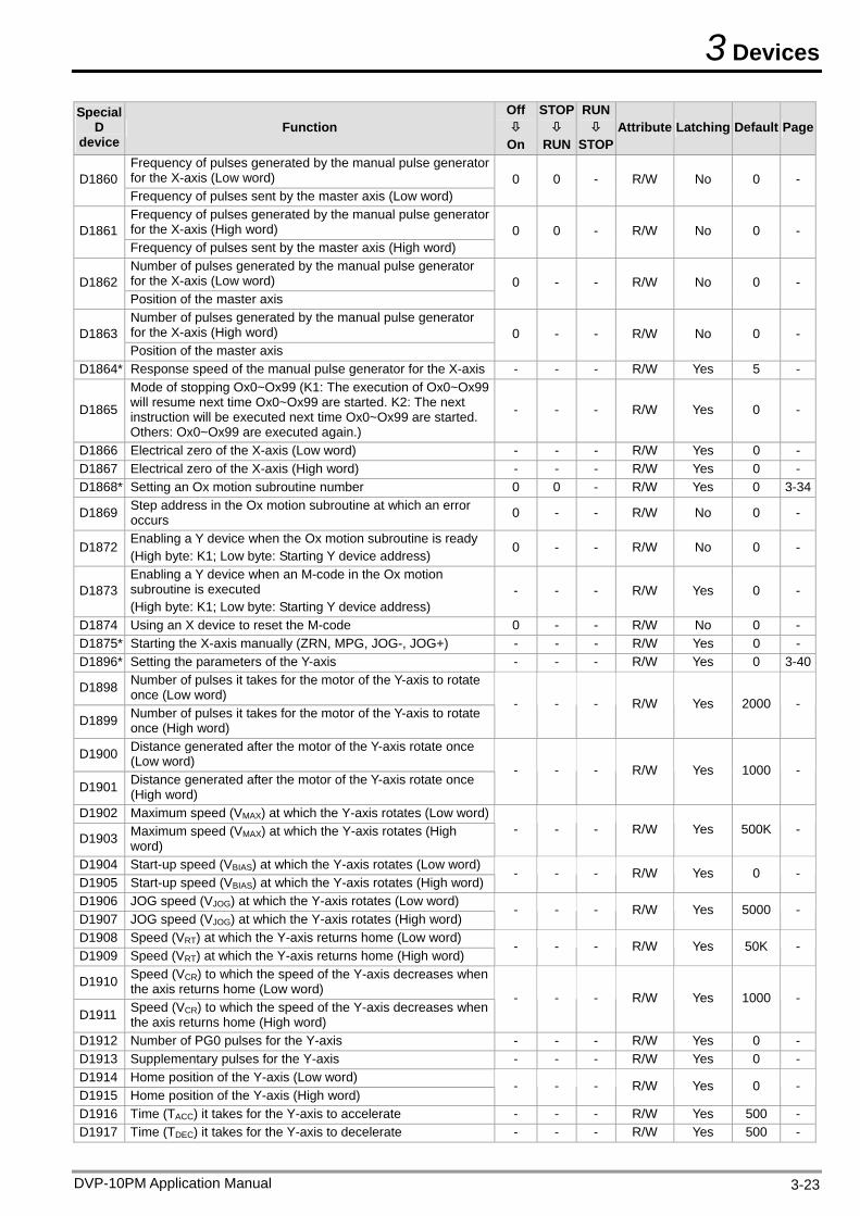
3 Devices
DVP-10PM Application Manual 3-23
Special D
device Function
Off
On
STOP
RUN
RUN
STOP Attribute Latching Default Page
Frequency of pulses generated by the manual pulse generator for the X-axis (Low word) D1860 Frequency of pulses sent by the master axis (Low word)
0 0 - R/W No 0 -
Frequency of pulses generated by the manual pulse generator for the X-axis (High word) D1861 Frequency of pulses sent by the master axis (High word)
0 0 - R/W No 0 -
Number of pulses generated by the manual pulse generator for the X-axis (Low word) D1862 Position of the master axis
0 - - R/W No 0 -
Number of pulses generated by the manual pulse generator for the X-axis (High word) D1863 Position of the master axis
0 - - R/W No 0 -
D1864* Response speed of the manual pulse generator for the X-axis - - - R/W Yes 5 -
D1865
Mode of stopping Ox0~Ox99 (K1: The execution of Ox0~Ox99 will resume next time Ox0~Ox99 are started. K2: The next instruction will be executed next time Ox0~Ox99 are started. Others: Ox0~Ox99 are executed again.)
- - - R/W Yes 0 -
D1866 Electrical zero of the X-axis (Low word) - - - R/W Yes 0 - D1867 Electrical zero of the X-axis (High word) - - - R/W Yes 0 - D1868* Setting an Ox motion subroutine number 0 0 - R/W Yes 0 3-34
D1869 Step address in the Ox motion subroutine at which an error occurs 0 - - R/W No 0 -
D1872 Enabling a Y device when the Ox motion subroutine is ready (High byte: K1; Low byte: Starting Y device address)
0 - - R/W No 0 -
D1873 Enabling a Y device when an M-code in the Ox motion subroutine is executed (High byte: K1; Low byte: Starting Y device address)
- - - R/W Yes 0 -
D1874 Using an X device to reset the M-code 0 - - R/W No 0 - D1875* Starting the X-axis manually (ZRN, MPG, JOG-, JOG+) - - - R/W Yes 0 - D1896* Setting the parameters of the Y-axis - - - R/W Yes 0 3-40
D1898 Number of pulses it takes for the motor of the Y-axis to rotate once (Low word)
D1899 Number of pulses it takes for the motor of the Y-axis to rotate once (High word)
- - - R/W Yes 2000 -
D1900 Distance generated after the motor of the Y-axis rotate once (Low word)
D1901 Distance generated after the motor of the Y-axis rotate once (High word)
- - - R/W Yes 1000 -
D1902 Maximum speed (VMAX) at which the Y-axis rotates (Low word)
D1903 Maximum speed (VMAX) at which the Y-axis rotates (High word)
- - - R/W Yes 500K -
D1904 Start-up speed (VBIAS) at which the Y-axis rotates (Low word) D1905 Start-up speed (VBIAS) at which the Y-axis rotates (High word)
- - - R/W Yes 0 -
D1906 JOG speed (VJOG) at which the Y-axis rotates (Low word) D1907 JOG speed (VJOG) at which the Y-axis rotates (High word)
- - - R/W Yes 5000 -
D1908 Speed (VRT) at which the Y-axis returns home (Low word) D1909 Speed (VRT) at which the Y-axis returns home (High word)
- - - R/W Yes 50K -
D1910 Speed (VCR) to which the speed of the Y-axis decreases when the axis returns home (Low word)
D1911 Speed (VCR) to which the speed of the Y-axis decreases when the axis returns home (High word)
- - - R/W Yes 1000 -
D1912 Number of PG0 pulses for the Y-axis - - - R/W Yes 0 - D1913 Supplementary pulses for the Y-axis - - - R/W Yes 0 - D1914 Home position of the Y-axis (Low word) D1915 Home position of the Y-axis (High word)
- - - R/W Yes 0 -
D1916 Time (TACC) it takes for the Y-axis to accelerate - - - R/W Yes 500 - D1917 Time (TDEC) it takes for the Y-axis to decelerate - - - R/W Yes 500 -
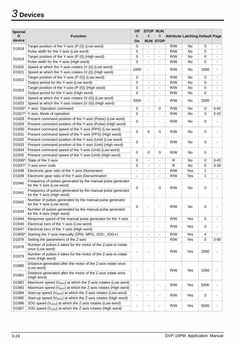
3 Devices
DVP-10PM Application Manual 3-24
Special D
device Function
Off
On
STOP
RUN
RUN
STOPAttribute Latching Default Page
Target position of the Y-axis (P (I)) (Low word) 0 - - R/W No 0 - D1918
Pulse width for the Y-axis (Low word) 0 - - R/W No 0 - Target position of the Y-axis (P (I)) (High word) 0 - - R/W No 0 -
D1919 Pulse width for the Y-axis (High word) 0 - - R/W No 0 -
D1920 Speed at which the Y-axis rotates (V (I)) (Low word) D1921 Speed at which the Y-axis rotates (V (I)) (High word)
1000 - - R/W No 1000 -
Target position of the Y-axis (P (II)) (Low word) 0 - - R/W No 0 - D1922
Output period for the Y-axis (Low word) 0 - - R/W No 0 - Target position of the Y-axis (P (II)) (High word) 0 - - R/W No 0 -
D1923 Output period for the Y-axis (High word) 0 - - R/W No 0 -
D1924 Speed at which the Y-axis rotates (V (II)) (Low word) D1925 Speed at which the Y-axis rotates (V (II)) (High word)
2000 - - R/W No 2000 -
D1926* Y-axis: Operation command 0 - 0 R/W No 0 3-42D1927* Y-axis: Mode of operation 0 - - R/W No 0 3-42D1928 Present command position of the Y-axis (Pulse) (Low word) D1929 Present command position of the Y-axis (Pulse) (High word)
0 - - R/W No 0 -
D1930 Present command speed of the Y-axis (PPS) (Low word) D1931 Present command speed of the Y-axis (PPS) (High word)
0 0 0 R/W No 0 -
D1932 Present command position of the Y-axis (Unit) (Low word) D1933 Present command position of the Y-axis (Unit) (High word)
0 - - R/W No 0 -
D1934 Present command speed of the Y-axis (Unit) (Low word) D1935 Present command speed of the Y-axis (Unit) (High word)
0 0 0 R/W No 0 -
D1936* State of the Y-axis 0 - - R No 0 3-43D1937* Y-axis error code 0 - - R No 0 3-39D1938 Electronic gear ratio of the Y-axis (Numerator) - - - R/W Yes 1 - D1939 Electronic gear ratio of the Y-axis (Denominator) - - - R/W Yes 1 -
D1940 Frequency of pulses generated by the manual pulse generator for the Y-axis (Low word)
D1941 Frequency of pulses generated by the manual pulse generator for the Y-axis (High word)
0 - 0 R/W No 0 -
D1942 Number of pulses generated by the manual pulse generator for the Y-axis (Low word)
D1943 Number of pulses generated by the manual pulse generator for the X-axis (High word)
0 - - R/W No 0 -
D1944 Response speed of the manual pulse generator for the Y-axis - - - R/W Yes 5 - D1946 Electrical zero of the Y-axis (Low word) D1947 Electrical zero of the Y-axis (High word)
- - - R/W Yes 0 -
D1955* Starting the Y-axis manually (ZRN, MPG, JOG-, JOG+) - - - R/W Yes 4 - D1976 Setting the parameters of the Z-axis - - - R/W Yes 0 3-40
D1978 Number of pulses it takes for the motor of the Z-axis to rotate once (Low word)
D1979 Number of pulses it takes for the motor of the Z-axis to rotate once (High word)
- - - R/W Yes 2000 -
D1980 Distance generated after the motor of the Z-axis rotate once (Low word)
D1981 Distance generated after the motor of the Z-axis rotate once (High word)
- - - R/W Yes 1000 -
D1982 Maximum speed (VMAX) at which the Z-axis rotates (Low word)D1983 Maximum speed (VMAX) at which the Z-axis rotates (High word)
- - - R/W Yes 500K -
D1984 Start-up speed (VBIAS) at which the Z-axis rotates (Low word) D1985 Start-up speed (VBIAS) at which the Z-axis rotates (High word)
- - - R/W Yes 0 -
D1986 JOG speed (VJOG) at which the Z-axis rotates (Low word) D1987 JOG speed (VJOG) at which the Z-axis rotates (High word)
- - - R/W Yes 5000 -
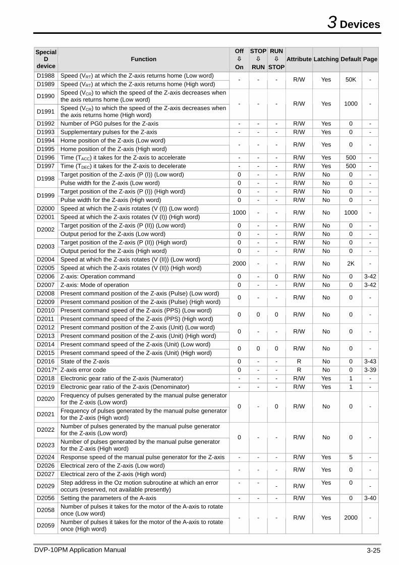
3 Devices
Special D
device Function
Off
On
STOP
RUN
RUN
STOP Attribute Latching Default Page
D1988 Speed (VRT) at which the Z-axis returns home (Low word) D1989 Speed (VRT) at which the Z-axis returns home (High word)
- - - R/W Yes 50K -
D1990 Speed (VCR) to which the speed of the Z-axis decreases when the axis returns home (Low word)
D1991 Speed (VCR) to which the speed of the Z-axis decreases when the axis returns home (High word)
- - - R/W Yes 1000 -
D1992 Number of PG0 pulses for the Z-axis - - - R/W Yes 0 - D1993 Supplementary pulses for the Z-axis - - - R/W Yes 0 - D1994 Home position of the Z-axis (Low word) D1995 Home position of the Z-axis (High word)
- - - R/W Yes 0 -
D1996 Time (TACC) it takes for the Z-axis to accelerate - - - R/W Yes 500 - D1997 Time (TDEC) it takes for the Z-axis to decelerate - - - R/W Yes 500 -
Target position of the Z-axis (P (I)) (Low word) 0 - - R/W No 0 - D1998
Pulse width for the Z-axis (Low word) 0 - - R/W No 0 - Target position of the Z-axis (P (I)) (High word) 0 - - R/W No 0 -
D1999 Pulse width for the Z-axis (High word) 0 - - R/W No 0 -
D2000 Speed at which the Z-axis rotates (V (I)) (Low word) D2001 Speed at which the Z-axis rotates (V (I)) (High word)
1000 - - R/W No 1000 -
Target position of the Z-axis (P (II)) (Low word) 0 - - R/W No 0 - D2002
Output period for the Z-axis (Low word) 0 - - R/W No 0 - Target position of the Z-axis (P (II)) (High word) 0 - - R/W No 0 -
D2003 Output period for the Z-axis (High word) 0 - - R/W No 0 -
D2004 Speed at which the Z-axis rotates (V (II)) (Low word) D2005 Speed at which the Z-axis rotates (V (II)) (High word)
2000 - - R/W No 2K -
D2006 Z-axis: Operation command 0 - 0 R/W No 0 3-42D2007 Z-axis: Mode of operation 0 - - R/W No 0 3-42D2008 Present command position of the Z-axis (Pulse) (Low word) D2009 Present command position of the Z-axis (Pulse) (High word)
0 - - R/W No 0 -
D2010 Present command speed of the Z-axis (PPS) (Low word) D2011 Present command speed of the Z-axis (PPS) (High word)
0 0 0 R/W No 0 -
D2012 Present command position of the Z-axis (Unit) (Low word) D2013 Present command position of the Z-axis (Unit) (High word)
0 - - R/W No 0 -
D2014 Present command speed of the Z-axis (Unit) (Low word) D2015 Present command speed of the Z-axis (Unit) (High word)
0 0 0 R/W No 0 -
D2016 State of the Z-axis 0 - - R No 0 3-43D2017* Z-axis error code 0 - - R No 0 3-39D2018 Electronic gear ratio of the Z-axis (Numerator) - - - R/W Yes 1 - D2019 Electronic gear ratio of the Z-axis (Denominator) - - - R/W Yes 1 -
D2020 Frequency of pulses generated by the manual pulse generator for the Z-axis (Low word)
D2021 Frequency of pulses generated by the manual pulse generator for the Z-axis (High word)
0 - 0 R/W No 0 -
D2022 Number of pulses generated by the manual pulse generator for the Z-axis (Low word)
D2023 Number of pulses generated by the manual pulse generator for the Z-axis (High word)
0 - - R/W No 0 -
D2024 Response speed of the manual pulse generator for the Z-axis - - - R/W Yes 5 - D2026 Electrical zero of the Z-axis (Low word) D2027 Electrical zero of the Z-axis (High word)
- - - R/W Yes 0 -
D2029 Step address in the Oz motion subroutine at which an error occurs (reserved, not available presently)
- - - R/W Yes 0 -
D2056 Setting the parameters of the A-axis - - - R/W Yes 0 3-40
D2058 Number of pulses it takes for the motor of the A-axis to rotate once (Low word)
D2059 Number of pulses it takes for the motor of the A-axis to rotate once (High word)
- - - R/W Yes 2000 -
DVP-10PM Application Manual 3-25
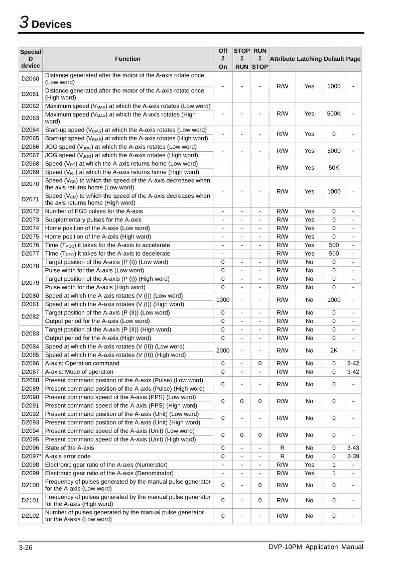
3 Devices
Special D
device Function
Off
On
STOP
RUN
RUN
STOPAttribute Latching Default Page
D2060 Distance generated after the motor of the A-axis rotate once (Low word)
D2061 Distance generated after the motor of the A-axis rotate once (High word)
- - - R/W Yes 1000 -
D2062 Maximum speed (VMAX) at which the A-axis rotates (Low word)
D2063 Maximum speed (VMAX) at which the A-axis rotates (High word)
- - - R/W Yes 500K -
D2064 Start-up speed (VBIAS) at which the A-axis rotates (Low word) D2065 Start-up speed (VBIAS) at which the A-axis rotates (High word)
- - - R/W Yes 0 -
D2066 JOG speed (VJOG) at which the A-axis rotates (Low word) D2067 JOG speed (VJOG) at which the A-axis rotates (High word)
- - - R/W Yes 5000 -
D2068 Speed (VRT) at which the A-axis returns home (Low word) D2069 Speed (VRT) at which the A-axis returns home (High word)
- - - R/W Yes 50K -
D2070 Speed (VCR) to which the speed of the A-axis decreases when the axis returns home (Low word)
D2071 Speed (VCR) to which the speed of the A-axis decreases when the axis returns home (High word)
- - - R/W Yes 1000 -
D2072 Number of PG0 pulses for the A-axis - - - R/W Yes 0 - D2073 Supplementary pulses for the A-axis - - - R/W Yes 0 - D2074 Home position of the A-axis (Low word) - - - R/W Yes 0 - D2075 Home position of the A-axis (High word) - - - R/W Yes 0 - D2076 Time (TACC) it takes for the A-axis to accelerate - - - R/W Yes 500 - D2077 Time (TDEC) it takes for the A-axis to decelerate - - - R/W Yes 500 -
Target position of the A-axis (P (I)) (Low word) 0 - - R/W No 0 - D2078
Pulse width for the A-axis (Low word) 0 - - R/W No 0 - Target position of the A-axis (P (I)) (High word) 0 - - R/W No 0 -
D2079 Pulse width for the A-axis (High word) 0 - - R/W No 0 -
D2080 Speed at which the A-axis rotates (V (I)) (Low word) D2081 Speed at which the A-axis rotates (V (I)) (High word)
1000 - - R/W No 1000 -
Target position of the A-axis (P (II)) (Low word) 0 - - R/W No 0 - D2082
Output period for the A-axis (Low word) 0 - - R/W No 0 - Target position of the A-axis (P (II)) (High word) 0 - - R/W No 0 -
D2083 Output period for the A-axis (High word) 0 - - R/W No 0 -
D2084 Speed at which the A-axis rotates (V (II)) (Low word) D2085 Speed at which the A-axis rotates (V (II)) (High word)
2000 - - R/W No 2K -
D2086 A-axis: Operation command 0 - 0 R/W No 0 3-42D2087 A-axis: Mode of operation 0 - - R/W No 0 3-42D2088 Present command position of the A-axis (Pulse) (Low word) D2089 Present command position of the A-axis (Pulse) (High word)
0 - - R/W No 0 -
D2090 Present command speed of the A-axis (PPS) (Low word) D2091 Present command speed of the A-axis (PPS) (High word)
0 0 0 R/W No 0 -
D2092 Present command position of the A-axis (Unit) (Low word) D2093 Present command position of the A-axis (Unit) (High word)
0 - - R/W No 0 -
D2094 Present command speed of the A-axis (Unit) (Low word) D2095 Present command speed of the A-axis (Unit) (High word)
0 0 0 R/W No 0 -
D2096 State of the A-axis 0 - - R No 0 3-43D2097* A-axis error code 0 - - R No 0 3-39D2098 Electronic gear ratio of the A-axis (Numerator) - - - R/W Yes 1 - D2099 Electronic gear ratio of the A-axis (Denominator) - - - R/W Yes 1 -
D2100 Frequency of pulses generated by the manual pulse generator for the A-axis (Low word) 0 - 0 R/W No 0 -
D2101 Frequency of pulses generated by the manual pulse generator for the A-axis (High word) 0 - 0 R/W No 0 -
D2102 Number of pulses generated by the manual pulse generator for the A-axis (Low word) 0 - - R/W No 0 -
DVP-10PM Application Manual 3-26
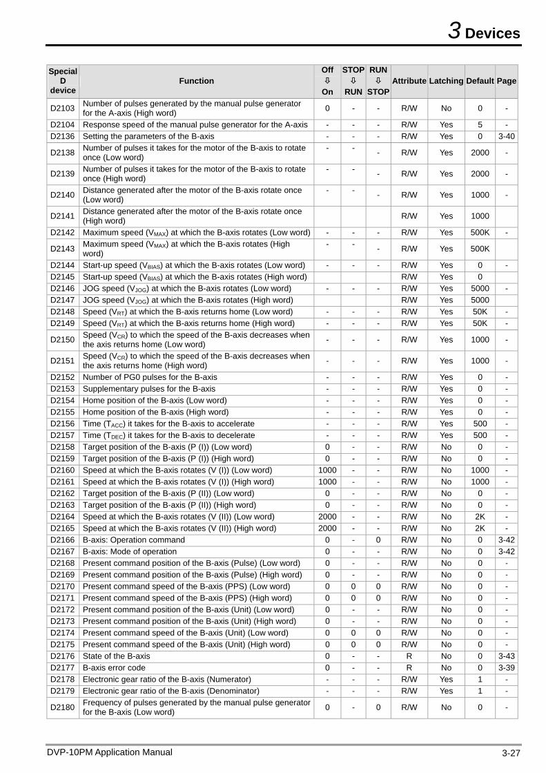
3 Devices
Special D
device Function
Off
On
STOP
RUN
RUN
STOP Attribute Latching Default Page
D2103 Number of pulses generated by the manual pulse generator for the A-axis (High word) 0 - - R/W No 0 -
D2104 Response speed of the manual pulse generator for the A-axis - - - R/W Yes 5 - D2136 Setting the parameters of the B-axis - - - R/W Yes 0 3-40
D2138 Number of pulses it takes for the motor of the B-axis to rotate once (Low word)
- - - R/W Yes 2000 -
D2139 Number of pulses it takes for the motor of the B-axis to rotate once (High word)
- - - R/W Yes 2000 -
D2140 Distance generated after the motor of the B-axis rotate once (Low word)
- - - R/W Yes 1000 -
D2141 Distance generated after the motor of the B-axis rotate once (High word)
R/W Yes 1000
D2142 Maximum speed (VMAX) at which the B-axis rotates (Low word) - - - R/W Yes 500K -
D2143 Maximum speed (VMAX) at which the B-axis rotates (High word)
- - - R/W Yes 500K
D2144 Start-up speed (VBIAS) at which the B-axis rotates (Low word) - - - R/W Yes 0 - D2145 Start-up speed (VBIAS) at which the B-axis rotates (High word) R/W Yes 0 D2146 JOG speed (VJOG) at which the B-axis rotates (Low word) - - - R/W Yes 5000 - D2147 JOG speed (VJOG) at which the B-axis rotates (High word) R/W Yes 5000 D2148 Speed (VRT) at which the B-axis returns home (Low word) - - - R/W Yes 50K - D2149 Speed (VRT) at which the B-axis returns home (High word) - - - R/W Yes 50K -
D2150 Speed (VCR) to which the speed of the B-axis decreases when the axis returns home (Low word) - - - R/W Yes 1000 -
D2151 Speed (VCR) to which the speed of the B-axis decreases when the axis returns home (High word) - - - R/W Yes 1000 -
D2152 Number of PG0 pulses for the B-axis - - - R/W Yes 0 - D2153 Supplementary pulses for the B-axis - - - R/W Yes 0 - D2154 Home position of the B-axis (Low word) - - - R/W Yes 0 - D2155 Home position of the B-axis (High word) - - - R/W Yes 0 - D2156 Time (TACC) it takes for the B-axis to accelerate - - - R/W Yes 500 - D2157 Time (TDEC) it takes for the B-axis to decelerate - - - R/W Yes 500 - D2158 Target position of the B-axis (P (I)) (Low word) 0 - - R/W No 0 - D2159 Target position of the B-axis (P (I)) (High word) 0 - - R/W No 0 - D2160 Speed at which the B-axis rotates (V (I)) (Low word) 1000 - - R/W No 1000 - D2161 Speed at which the B-axis rotates (V (I)) (High word) 1000 - - R/W No 1000 - D2162 Target position of the B-axis (P (II)) (Low word) 0 - - R/W No 0 - D2163 Target position of the B-axis (P (II)) (High word) 0 - - R/W No 0 - D2164 Speed at which the B-axis rotates (V (II)) (Low word) 2000 - - R/W No 2K - D2165 Speed at which the B-axis rotates (V (II)) (High word) 2000 - - R/W No 2K - D2166 B-axis: Operation command 0 - 0 R/W No 0 3-42D2167 B-axis: Mode of operation 0 - - R/W No 0 3-42D2168 Present command position of the B-axis (Pulse) (Low word) 0 - - R/W No 0 - D2169 Present command position of the B-axis (Pulse) (High word) 0 - - R/W No 0 - D2170 Present command speed of the B-axis (PPS) (Low word) 0 0 0 R/W No 0 - D2171 Present command speed of the B-axis (PPS) (High word) 0 0 0 R/W No 0 - D2172 Present command position of the B-axis (Unit) (Low word) 0 - - R/W No 0 - D2173 Present command position of the B-axis (Unit) (High word) 0 - - R/W No 0 - D2174 Present command speed of the B-axis (Unit) (Low word) 0 0 0 R/W No 0 - D2175 Present command speed of the B-axis (Unit) (High word) 0 0 0 R/W No 0 - D2176 State of the B-axis 0 - - R No 0 3-43D2177 B-axis error code 0 - - R No 0 3-39D2178 Electronic gear ratio of the B-axis (Numerator) - - - R/W Yes 1 - D2179 Electronic gear ratio of the B-axis (Denominator) - - - R/W Yes 1 -
D2180 Frequency of pulses generated by the manual pulse generator for the B-axis (Low word) 0 - 0 R/W No 0 -
DVP-10PM Application Manual 3-27
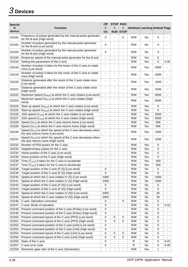
3 Devices
Special D
device Function
Off
On
STOP
RUN
RUN
STOPAttribute Latching Default Page
D2181 Frequency of pulses generated by the manual pulse generator for the B-axis (High word) 0 - 0 R/W No 0 -
D2182 Number of pulses generated by the manual pulse generator for the B-axis (Low word) 0 - - R/W No 0 -
D2183 Number of pulses generated by the manual pulse generator for the B-axis (High word) 0 - - R/W No 0 -
D2184 Response speed of the manual pulse generator for the B-axis - - - R/W Yes 5 - D2216 Setting the parameters of the C-axis - - - R/W Yes 0 3-40
D2218 Number of pulses it takes for the motor of the C-axis to rotate once (Low word)
- - - R/W Yes 2000 -
D2219 Number of pulses it takes for the motor of the C-axis to rotate once (High word)
- - - R/W Yes 2000 -
D2220 Distance generated after the motor of the C-axis rotate once (Low word)
- - - R/W Yes 1000 -
D2221 Distance generated after the motor of the C-axis rotate once (High word)
- - - R/W Yes 1000 -
D2222 Maximum speed (VMAX) at which the C-axis rotates (Low word) - - - R/W Yes 500K -
D2223 Maximum speed (VMAX) at which the C-axis rotates (High word)
- - - R/W Yes 500K -
D2224 Start-up speed (VBIAS) at which the C-axis rotates (Low word) - - - R/W Yes 0 - D2225 Start-up speed (VBIAS) at which the C-axis rotates (High word) - - - R/W Yes 0 - D2226 JOG speed (VJOG) at which the C-axis rotates (Low word) - - - R/W Yes 5000 - D2227 JOG speed (VJOG) at which the C-axis rotates (High word) - - - R/W Yes 5000 - D2228 Speed (VRT) at which the C-axis returns home (Low word) - - - R/W Yes 50K - D2229 Speed (VRT) at which the C-axis returns home (High word) - - - R/W Yes 50K -
D2230 Speed (VCR) to which the speed of the C-axis decreases when the axis returns home (Low word) - - - R/W Yes 1000 -
D2231 Speed (VCR) to which the speed of the C-axis decreases when the axis returns home (High word) - - - R/W Yes 1000 -
D2232 Number of PG0 pulses for the C-axis - - - R/W Yes 0 - D2233 Supplementary pulses for the C-axis - - - R/W Yes 0 - D2234 Home position of the C-axis (Low word) - - - R/W Yes 0 - D2235 Home position of the C-axis (High word) - - - R/W Yes 0 - D2236 Time (TACC) it takes for the C-axis to accelerate - - - R/W Yes 500 - D2237 Time (TDEC) it takes for the C-axis to decelerate - - - R/W Yes 500 - D2238 Target position of the C-axis (P (I)) (Low word) 0 - - R/W No 0 - D2239 Target position of the C-axis (P (I)) (High word) 0 - - R/W No 0 - D2240 Speed at which the C-axis rotates (V (I)) (Low word) 1000 - - R/W No 1000 - D2241 Speed at which the C-axis rotates (V (I)) (High word) 1000 - - R/W No 1000 - D2242 Target position of the C-axis (P (II)) (Low word) 0 - - R/W No 0 - D2243 Target position of the C-axis (P (II)) (High word) 0 - - R/W No 0 - D2244 Speed at which the C-axis rotates (V (II)) (Low word) 2000 - - R/W No 2K - D2245 Speed at which the C-axis rotates (V (II)) (High word) 2000 - - R/W No 2K - D2246 C-axis: Operation command 0 - 0 R/W No 0 - D2247 C-axis: Mode of operation 0 - - R/W No 0 3-42D2248 Present command position of the C-axis (Pulse) (Low word) 0 - - R/W No 0 - D2249 Present command position of the C-axis (Pulse) (High word) 0 - - R/W No 0 - D2250 Present command speed of the C-axis (PPS) (Low word) 0 0 0 R/W No 0 - D2251 Present command speed of the C-axis (PPS) (High word) 0 0 0 R/W No 0 - D2252 Present command position of the C-axis (Unit) (Low word) 0 - - R/W No 0 - D2253 Present command position of the C-axis (Unit) (High word) 0 - - R/W No 0 - D2254 Present command speed of the C-axis (Unit) (Low word) 0 0 0 R/W No 0 - D2255 Present command speed of the C-axis (Unit) (High word) 0 0 0 R/W No 0 - D2256 State of the C-axis 0 - - R No 0 3-43D2257 C-axis error code 0 - - R No 0 3-39D2258 Electronic gear ratio of the C-axis (Numerator) - - - R/W Yes 1 -
DVP-10PM Application Manual 3-28
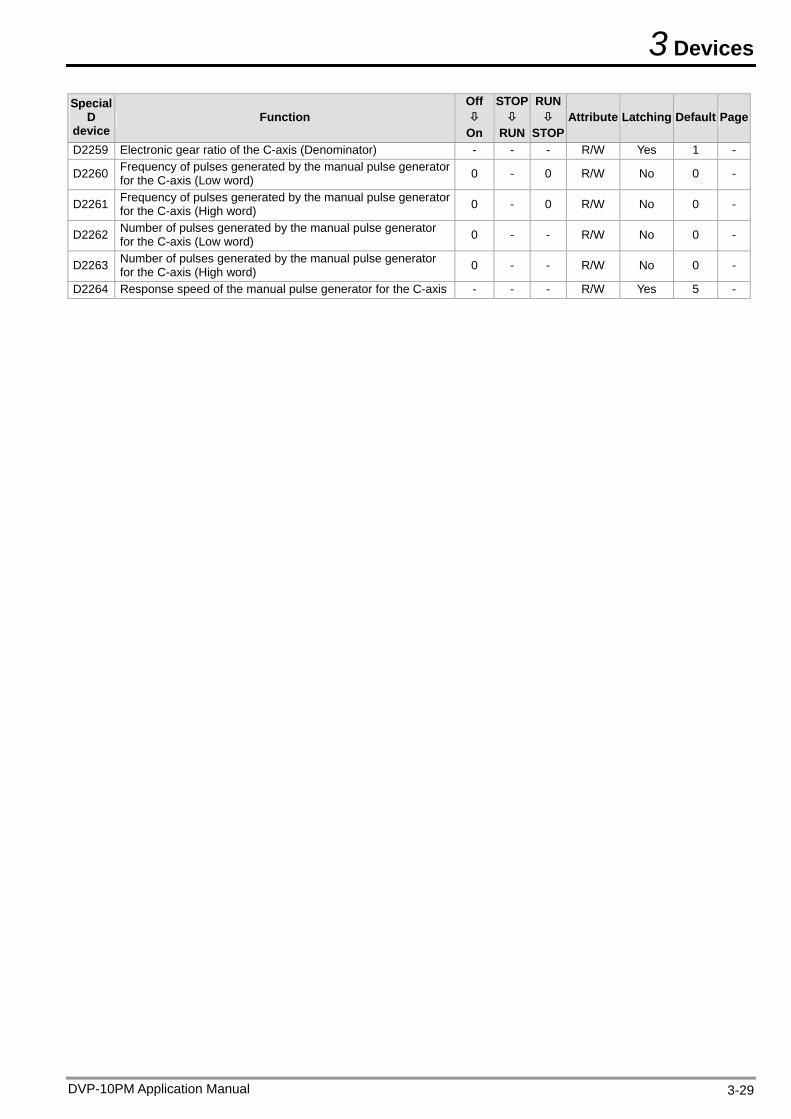
3 Devices
Special D
device Function
Off
On
STOP
RUN
RUN
STOP Attribute Latching Default Page
D2259 Electronic gear ratio of the C-axis (Denominator) - - - R/W Yes 1 -
D2260 Frequency of pulses generated by the manual pulse generator for the C-axis (Low word) 0 - 0 R/W No 0 -
D2261 Frequency of pulses generated by the manual pulse generator for the C-axis (High word) 0 - 0 R/W No 0 -
D2262 Number of pulses generated by the manual pulse generator for the C-axis (Low word) 0 - - R/W No 0 -
D2263 Number of pulses generated by the manual pulse generator for the C-axis (High word) 0 - - R/W No 0 -
D2264 Response speed of the manual pulse generator for the C-axis - - - R/W Yes 5 -
DVP-10PM Application Manual 3-29
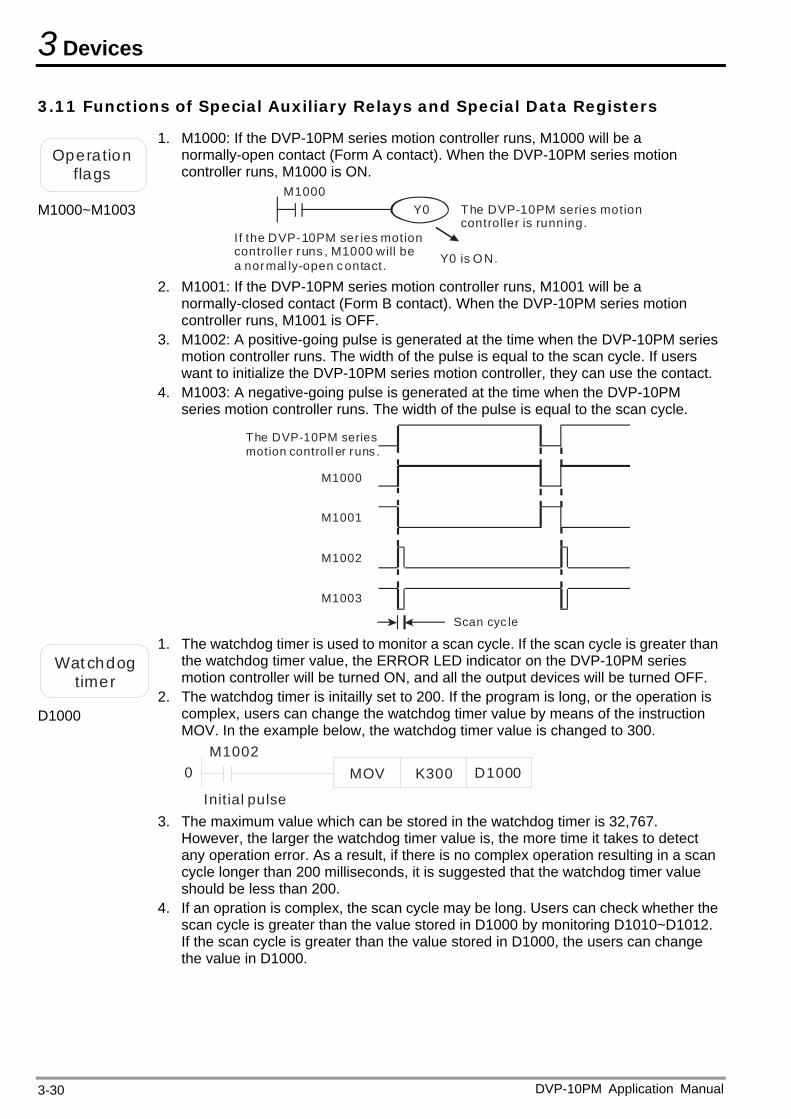
3 Devices
3.11 Functions of Special Auxiliary Relays and Special Data Registers
Operationflags
M1000~M1003
1. M1000: If the DVP-10PM series motion controller runs, M1000 will be a normally-open contact (Form A contact). When the DVP-10PM series motion controller runs, M1000 is ON.
M1000Y0 The
is running.DVP-10PM series motion
controller
Y0 is ON.
If the DVP-10PM ser ies motion controller runs , M1000 will be a normal ly-open contact.
2. M1001: If the DVP-10PM series motion controller runs, M1001 will be a normally-closed contact (Form B contact). When the DVP-10PM series motion controller runs, M1001 is OFF.
3. M1002: A positive-going pulse is generated at the time when the DVP-10PM series motion controller runs. The width of the pulse is equal to the scan cycle. If users want to initialize the DVP-10PM series motion controller, they can use the contact.
4. M1003: A negative-going pulse is generated at the time when the DVP-10PM series motion controller runs. The width of the pulse is equal to the scan cycle.
The DVP-10PM series motion controll er runs .
M1000
M1001
M1002
M1003
Scan cyc le
Wat chdotimer
g
D1000
1. The watchdog timer is used to monitor a scan cycle. If the scan cycle is greater than the watchdog timer value, the ERROR LED indicator on the DVP-10PM series motion controller will be turned ON, and all the output devices will be turned OFF.
2. The watchdog timer is initailly set to 200. If the program is long, or the operation is complex, users can change the watchdog timer value by means of the instruction MOV. In the example below, the watchdog timer value is changed to 300.
M1002
Init ial pulse
0 MOV K300 D1000
3. The maximum value which can be stored in the watchdog timer is 32,767.
However, the larger the watchdog timer value is, the more time it takes to detect any operation error. As a result, if there is no complex operation resulting in a scan cycle longer than 200 milliseconds, it is suggested that the watchdog timer value should be less than 200.
4. If an opration is complex, the scan cycle may be long. Users can check whether the scan cycle is greater than the value stored in D1000 by monitoring D1010~D1012. If the scan cycle is greater than the value stored in D1000, the users can change the value in D1000.
DVP-10PM Application Manual 3-30
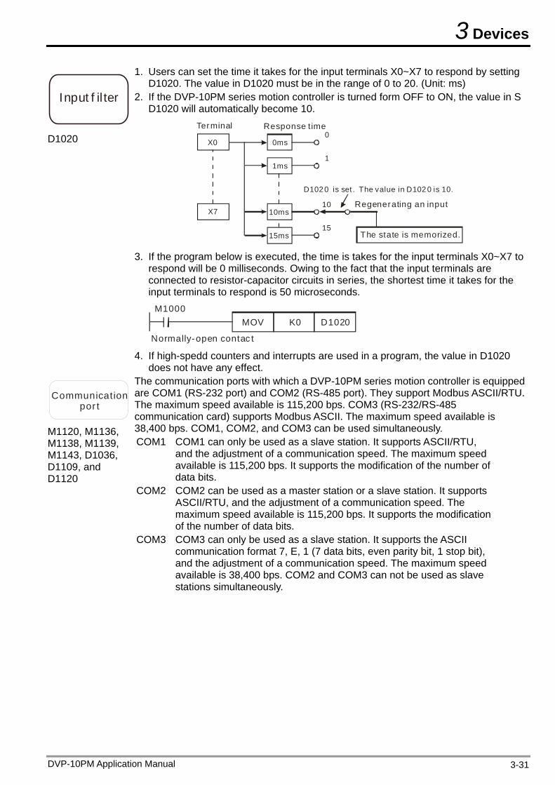
3 Devices
Input f il ter
D1020
1. Users can set the time it takes for the input terminals X0~X7 to respond by setting D1020. The value in D1020 must be in the range of 0 to 20. (Unit: ms)
2. If the DVP-10PM series motion controller is turned form OFF to ON, the value in S D1020 will automatically become 10.
X0
X7
0ms
1ms
10ms
15ms
Terminal Response t ime
Regenerating an input
The state is memorized.
0
1
10
15
D102 0 is set . The value in D102 0 is 10.
3. If the program below is executed, the time is takes for the input terminals X0~X7 to
respond will be 0 milliseconds. Owing to the fact that the input terminals are connected to resistor-capacitor circuits in series, the shortest time it takes for the input terminals to respond is 50 microseconds.
M1000
Normally-open contac t
MOV K0 D1020
4. If high-spedd counters and interrupts are used in a program, the value in D1020
does not have any effect.
Communication por t
M1120, M1136, M1138, M1139, M1143, D1036, D1109, and D1120
The communication ports with which a DVP-10PM series motion controller is equipped are COM1 (RS-232 port) and COM2 (RS-485 port). They support Modbus ASCII/RTU. The maximum speed available is 115,200 bps. COM3 (RS-232/RS-485 communication card) supports Modbus ASCII. The maximum speed available is 38,400 bps. COM1, COM2, and COM3 can be used simultaneously. COM1 COM1 can only be used as a slave station. It supports ASCII/RTU,
and the adjustment of a communication speed. The maximum speed available is 115,200 bps. It supports the modification of the number of data bits.
COM2 COM2 can be used as a master station or a slave station. It supports ASCII/RTU, and the adjustment of a communication speed. The maximum speed available is 115,200 bps. It supports the modification of the number of data bits.
COM3 COM3 can only be used as a slave station. It supports the ASCII communication format 7, E, 1 (7 data bits, even parity bit, 1 stop bit), and the adjustment of a communication speed. The maximum speed available is 38,400 bps. COM2 and COM3 can not be used as slave stations simultaneously.
DVP-10PM Application Manual 3-31
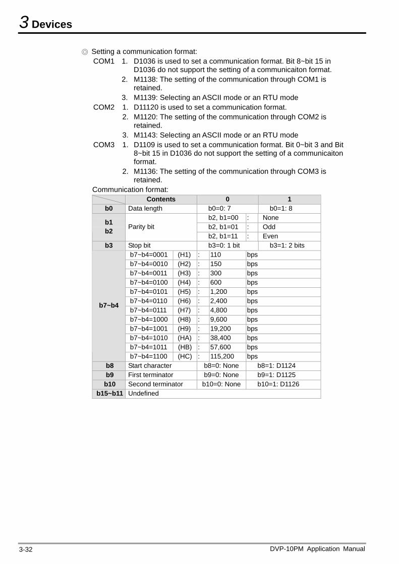
3 Devices
Setting a communication format: COM1 1. D1036 is used to set a communication format. Bit 8~bit 15 in
D1036 do not support the setting of a communicaiton format. 2. M1138: The setting of the communication through COM1 is
retained. 3. M1139: Selecting an ASCII mode or an RTU mode
COM2 1. D11120 is used to set a communication format. 2. M1120: The setting of the communication through COM2 is
retained. 3. M1143: Selecting an ASCII mode or an RTU mode
COM3 1. D1109 is used to set a communication format. Bit 0~bit 3 and Bit 8~bit 15 in D1036 do not support the setting of a communicaiton format.
2. M1136: The setting of the communication through COM3 is retained.
Communication format: Contents 0 1
b0 Data length b0=0: 7 b0=1: 8 b2, b1=00 : None b2, b1=01 : Odd
b1 b2 Parity bit
b2, b1=11 : Even b3 Stop bit b3=0: 1 bit b3=1: 2 bits
b7~b4=0001 (H1) : 110 bps b7~b4=0010 (H2) : 150 bps b7~b4=0011 (H3) : 300 bps b7~b4=0100 (H4) : 600 bps b7~b4=0101 (H5) : 1,200 bps b7~b4=0110 (H6) : 2,400 bps b7~b4=0111 (H7) : 4,800 bps b7~b4=1000 (H8) : 9,600 bps b7~b4=1001 (H9) : 19,200 bps b7~b4=1010 (HA) : 38,400 bps b7~b4=1011 (HB) : 57,600 bps
b7~b4
b7~b4=1100 (HC) : 115,200 bps b8 Start character b8=0: None b8=1: D1124 b9 First terminator b9=0: None b9=1: D1125 b10 Second terminator b10=0: None b10=1: D1126
b15~b11 Undefined
DVP-10PM Application Manual 3-32
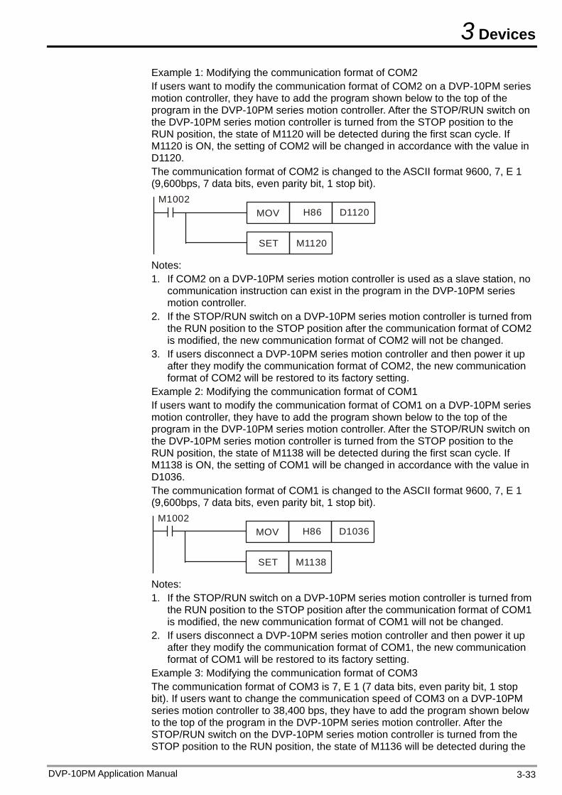
3 Devices
Example 1: Modifying the communication format of COM2 If users want to modify the communication format of COM2 on a DVP-10PM series motion controller, they have to add the program shown below to the top of the program in the DVP-10PM series motion controller. After the STOP/RUN switch on the DVP-10PM series motion controller is turned from the STOP position to the RUN position, the state of M1120 will be detected during the first scan cycle. If M1120 is ON, the setting of COM2 will be changed in accordance with the value in D1120. The communication format of COM2 is changed to the ASCII format 9600, 7, E 1 (9,600bps, 7 data bits, even parity bit, 1 stop bit).
MOV H86 D1120
SET M1120
M1002
Notes: 1. If COM2 on a DVP-10PM series motion controller is used as a slave station, no
communication instruction can exist in the program in the DVP-10PM series motion controller.
2. If the STOP/RUN switch on a DVP-10PM series motion controller is turned from the RUN position to the STOP position after the communication format of COM2 is modified, the new communication format of COM2 will not be changed.
3. If users disconnect a DVP-10PM series motion controller and then power it up after they modify the communication format of COM2, the new communication format of COM2 will be restored to its factory setting.
Example 2: Modifying the communication format of COM1 If users want to modify the communication format of COM1 on a DVP-10PM series motion controller, they have to add the program shown below to the top of the program in the DVP-10PM series motion controller. After the STOP/RUN switch on the DVP-10PM series motion controller is turned from the STOP position to the RUN position, the state of M1138 will be detected during the first scan cycle. If M1138 is ON, the setting of COM1 will be changed in accordance with the value in D1036. The communication format of COM1 is changed to the ASCII format 9600, 7, E 1 (9,600bps, 7 data bits, even parity bit, 1 stop bit).
MOV H86 D1036
SET M1138
M1002
Notes: 1. If the STOP/RUN switch on a DVP-10PM series motion controller is turned from
the RUN position to the STOP position after the communication format of COM1 is modified, the new communication format of COM1 will not be changed.
2. If users disconnect a DVP-10PM series motion controller and then power it up after they modify the communication format of COM1, the new communication format of COM1 will be restored to its factory setting.
Example 3: Modifying the communication format of COM3 The communication format of COM3 is 7, E 1 (7 data bits, even parity bit, 1 stop bit). If users want to change the communication speed of COM3 on a DVP-10PM series motion controller to 38,400 bps, they have to add the program shown below to the top of the program in the DVP-10PM series motion controller. After the STOP/RUN switch on the DVP-10PM series motion controller is turned from the STOP position to the RUN position, the state of M1136 will be detected during the
DVP-10PM Application Manual 3-33
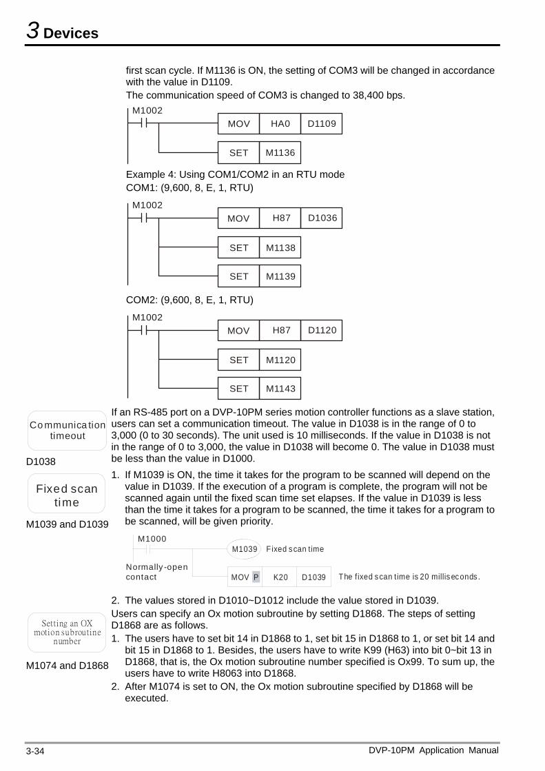
3 Devices
DVP-10PM Application Manual 3-34
first scan cycle. If M1136 is ON, the setting of COM3 will be changed in accordance with the value in D1109. The communication speed of COM3 is changed to 38,400 bps.
MOV HA0 D1109
SET M1136
M1002
Example 4: Using COM1/COM2 in an RTU mode COM1: (9,600, 8, E, 1, RTU)
MOV H87 D1036
SET M1138
M1002
SET M1139
COM2: (9,600, 8, E, 1, RTU)
MOV H87 D1120
SET M1120
M1002
SET M1143
Co mmunica tion timeout
D1038
If an RS-485 port on a DVP-10PM series motion controller functions as a slave station, users can set a communication timeout. The value in D1038 is in the range of 0 to 3,000 (0 to 30 seconds). The unit used is 10 milliseconds. If the value in D1038 is not in the range of 0 to 3,000, the value in D1038 will become 0. The value in D1038 must be less than the value in D1000.
Fixed scan time
M1039 and D103
1. If M1039 is ON, the time it takes for the program to be scanned will depend on the
9
v
alue in D1039. If the execution of a program is complete, the program will not be scanned again until the fixed scan time set elapses. If the value in D1039 is less than the time it takes for a program to be scanned, the time it takes for a program tobe scanned, will be given priority.
M1039 Fixed scan timeM1000
Normally -open contact D1039K20MOV P The fixed scan time is 20 millis econds .
2. The values stored in D1010~D1012 include the value stored in D1039.
Setting an OX motion subroutine
number
M1074 and D 8681b
Users can specify an Ox motion subroutine by setting D1868. The steps of setting D1868 are as follows. 1. The users have to set bit 14 in D1868 to 1, set bit 15 in D1868 to 1, or set bit 14 and
it 15 in D1868 to 1. Besides, the users have to write K99 (H63) into bit 0~bit 13 in D1868, that is, the Ox motion subroutine number specified is Ox99. To sum up, the users have to write H8063 into D1868. After M1074 is set to ON, the Ox motion subroutine specified by D1868 will be 2. executed.
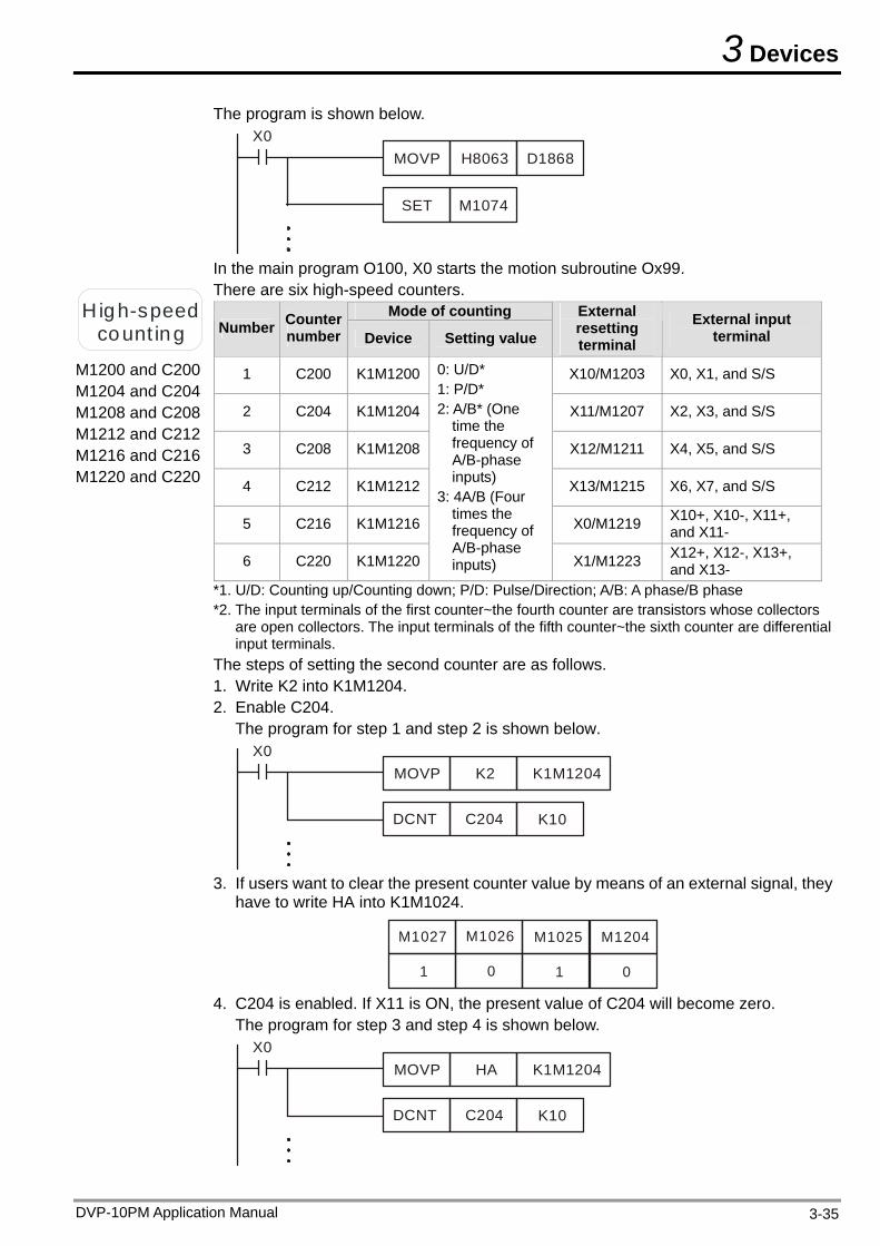
3 Devices
DVP-10PM Application Manual 3-35
The program is shown below.
MOVP H8063 D1868
SET M1074
X0
In the main program O100, X0 starts the motion subroutine Ox99.
H igh-speed count ing
M1200 and C200
M1204 and C204 M1208 and C208 M1212 and C212 M1216 and C216 M1220 and C220
There are six high-speed counters. Mode of counting
Number Counter number Device Setting value
External resetting terminal
External input terminal
1 C200 K1M1200 X X0, X1, and S/S 10/M1203
2 C204 K1M1204 X11/M1207 X2, X3, and S/S
3 C208 K1M1208 X12/M1211 X4, X5, and S/S
4 C212 K1M1212 X13/M1215 X6, X7, and S/S
5 C216 K1M1216 X0/M1219 , X10+, X10-, X11+and X11-
6 C220 K1M1220
0
f
3: 4A/B (Four
f
X1/M1223 -, X13+,
: U/D* 1: P/D* 2: A/B* (One
time the frequency oA/B-phase inputs)
times the frequency oA/B-phase inputs)
X12+, X12and X13-
*1. U/D: Cou p/ own lse/Direc ha ctors
l
Th g the second counter are as follows.
r step 1 and step 2 is shown below.
nting u Counting d ; P/D: Pu tion; A/B: A p se/B phase*2. The input terminals of the first counter~the fourth counter are transistors whose colle
are open collectors. The input terminals of the fifth counter~the sixth counter are differentiainput terminals. e steps of settin
1. Write K2 into K1M1204. 2. Enable C204.
The program fo
MOVP K2 K1M1204X0
DCNT C204 K10
3. If users want to clear the present counter value by means of an external signal, they
have to write HA into K1M1024.
M1204M1025M1026M1027
0101
4. C204 is enabled. If X11 is ON, the present value of C204 will become zero. The program for step 3 and step 4 is shown below.
MOVP HA K1M1204X0
DCNT C204 K10
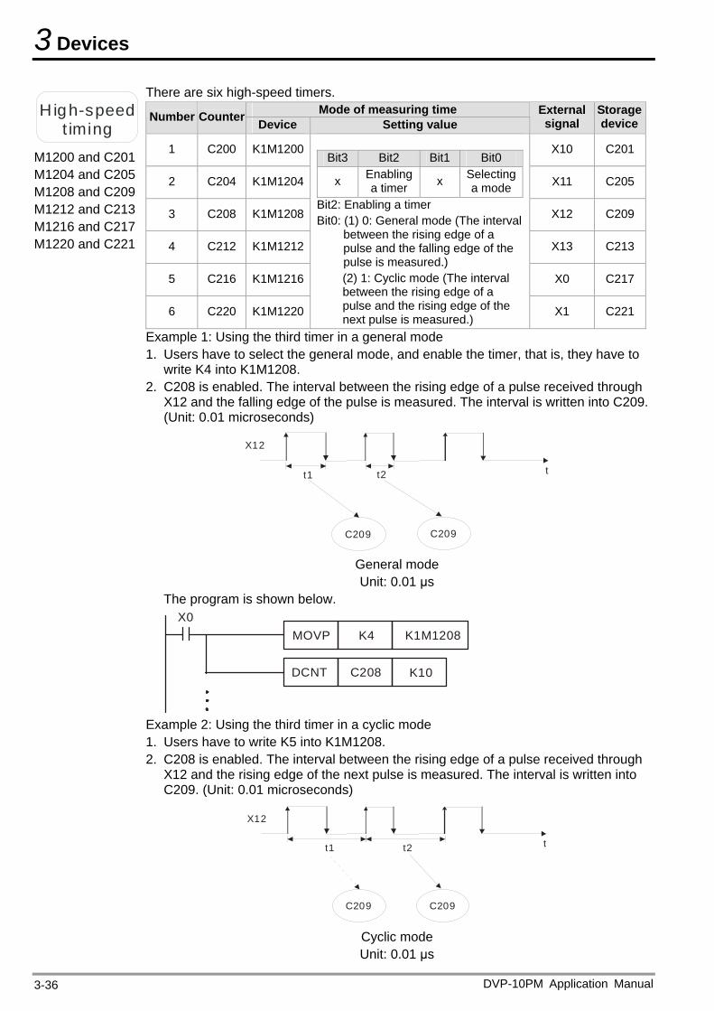
3 Devices
H igh-speed t iming
M1200 and C201 M1204 and C205 M1208 and C209 M1212 and C213 M1216 and C217 M1220 and C221
There are six high-speed timers. Mode of measuring time Number Counter Device Setting value
External signal
Storage device
1 C200 K1M1200 X10 C201
2 C204 K1M1204 X11 C205
3 C208 K1M1208 X12 C209
4 C212 K1M1212 X13 C213
5 C216 K1M1216 X0 C217
6 C220 K1M1220
Bit3 Bit2 Bit1 Bit0
x Enabling a timer x Selecting
a mode Bit2: Enabling a timer Bit0: (1) 0: General mode (The interval
between the rising edge of a pulse and the falling edge of the pulse is measured.) (2) 1: Cyclic mode (The interval between the rising edge of a pulse and the rising edge of the next pulse is measured.)
X1 C221
Example 1: Using the third timer in a general mode 1. Users have to select the general mode, and enable the timer, that is, they have to
write K4 into K1M1208. 2. C208 is enabled. The interval between the rising edge of a pulse received through
X12 and the falling edge of the pulse is measured. The interval is written into C209. (Unit: 0.01 microseconds)
t1 t2
X12
t
C209 C209
General mode Unit: 0.01 μs
The program is shown below.
MOVP K4 K1M1208X0
DCNT C208 K10
Example 2: Using the third timer in a cyclic mode 1. Users have to write K5 into K1M1208. 2. C208 is enabled. The interval between the rising edge of a pulse received through
X12 and the rising edge of the next pulse is measured. The interval is written into C209. (Unit: 0.01 microseconds)
t1 t2
X12
t
C209 C209
Cyclic mode Unit: 0.01 μs
DVP-10PM Application Manual 3-36
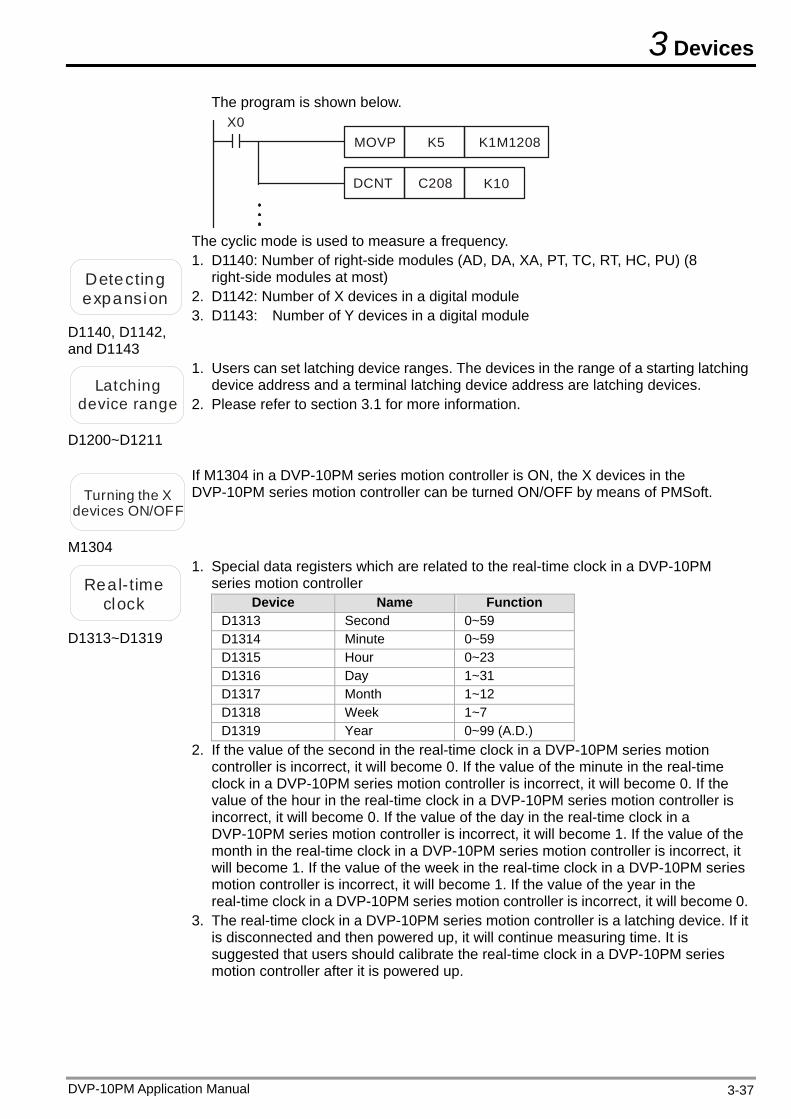
3 Devices
DVP-10PM Application Manual 3-37
The program is shown below.
MOVP K5 K1M1208X0
DCNT C208 K10
The cyclic mode is used to measure a frequency.
Detectinexpans
g ion
D1140, D1142, and D1143
1. D1140: Number of right-side modules (AD, DA, XA, PT, TC, RT, HC, PU) (8 right-side modules at most)
2. D1142: Number of X devices in a digital module 3. D1143: Number of Y devices in a digital module
Latching 1.
device range 2. Please refer to section 3.1 for more information.
D1200~D1211
Users can set latching device ranges. The devices in the range of a starting latching device address and a terminal latching device address are latching devices.
Turning the X devices ON/OFF
M1304
If M1304 in a DVP-10PM series motion controller is ON, the X devices in the DVP-10PM series motion controller can be turned ON/OFF by means of PMSoft.
Real-timeclock
D1313~D1319
1. Special data registers which are related to the real-time clock in a DVP-10PM series motion controller
Device Name Function D1313 Second 0~59 D1314 Minute 0~59 D1315 Hour 0~23 D1316 Day 1~31 D1317 Month 1~12 D1318 Week 1~7 D1319 Year 0~99 (A.D.)
2. If the value of the second in the real-time clock in a DVP-10PM series motion controller is incorrect, it will become 0. If the value of the minute in the real-time clock in a DVP-10PM series motion controller is incorrect, it will become 0. If the value of the hour in the real-time clock in a DVP-10PM series motion controller is incorrect, it will become 0. If the value of the day in the real-time clock in a DVP-10PM series motion controller is incorrect, it will become 1. If the value of the month in the real-time clock in a DVP-10PM series motion controller is incorrect, it will become 1. If the value of the week in the real-time clock in a DVP-10PM series motion controller is incorrect, it will become 1. If the value of the year in the real-time clock in a DVP-10PM series motion controller is incorrect, it will become 0.
3. The real-time clock in a DVP-10PM series motion controller is a latching device. If it is disconnected and then powered up, it will continue measuring time. It is suggested that users should calibrate the real-time clock in a DVP-10PM series motion controller after it is powered up.
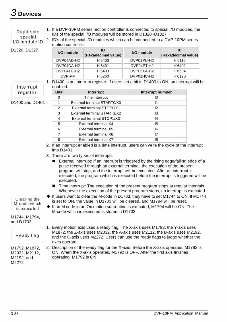
3 Devices
DVP-10PM Application Manual 3-38
Right-spec
I/O mod
side ia l ule ID
D1320~D1327
1. If a DVP-10PM series motion controller is connected to special I/O modules, the IDs of the special I/O modules will be stored in D1320~D1327.
2. ID’s of the special I/O modules which can be connected to a DVP-10PM series motion controller:
I/O module ID (Hexadecimal value) I/O module ID
(Hexadecimal value) DVP04AD-H2 H’6400 DVP01PU-H2 H’6110 DVP04DA-H2 H’6401 DVP04PT-H2 H’6402 DVP04TC-H2 H’6403 DVP06XA-H2 H’6604
DVP-PM H’6260 DVP01HC-H2 H’6120
In terrupregister
t
D1400 and D1401
1. D1400 is an interrupt register. If users set a bit in D1400 to ON, an interrupt will be enabled.
Bit# Interrupt Interrupt number 0 Time interrupt I0 1 External terminal START0/X0 I1 2 External terminal STOP0/X1 I2 3 External terminal START1/X2 I3 4 External terminal STOP1/X3 I4 5 External terminal X4 I5 6 External terminal X5 I6 7 External terminal X6 I7 8 External terminal X7 I8
2. If an interrupt enabled is a time interrupt, users can write the cycle of the interrupt into D1401.
3. There are two types of interrupts. External interrupt: If an interrupt is triggered by the rising edge/falling edge of a
pulse received through an external terminal, the execution of the present program will stop, and the interrupt will be executed. After an interrupt is executed, the program which is executed before the interrupt is triggered will be executed.
Time interrupt: The execution of the present program stops at regular intervals. Whenever the execution of the present program stops, an interrupt is executed.
Clearing the If users want to clear the M-code in D1703, they have to set M1744 to ON. If M1744
is set to ON, the value in D1703 will be cleared, and M1794 will be reset. M-code wis exec
hich u ted If an M code in an Ox motion subroutine is executed, M1794 will be ON. The
M-code which is executed is stored in D1703. M1744, M1794, and D1703
Ready f lag
M1792, M1872, M2032, M2112, M2192, and M2272
1. Every motion axis uses a ready flag. The X-axis uses M1792, the Y-axis uses M1872, the Z-axis uses M2032, the A-axis uses M2112, the B-axis uses M2192, and the C-axis uses M2272. Users can use the ready flags to judge whether the axes operate.
2. Description of the ready flag for the X-axis: Before the X-axis operates, M1792 is ON. When the X-axis operates, M1792 is OFF. After the first axis finishes operating, M1792 is ON.
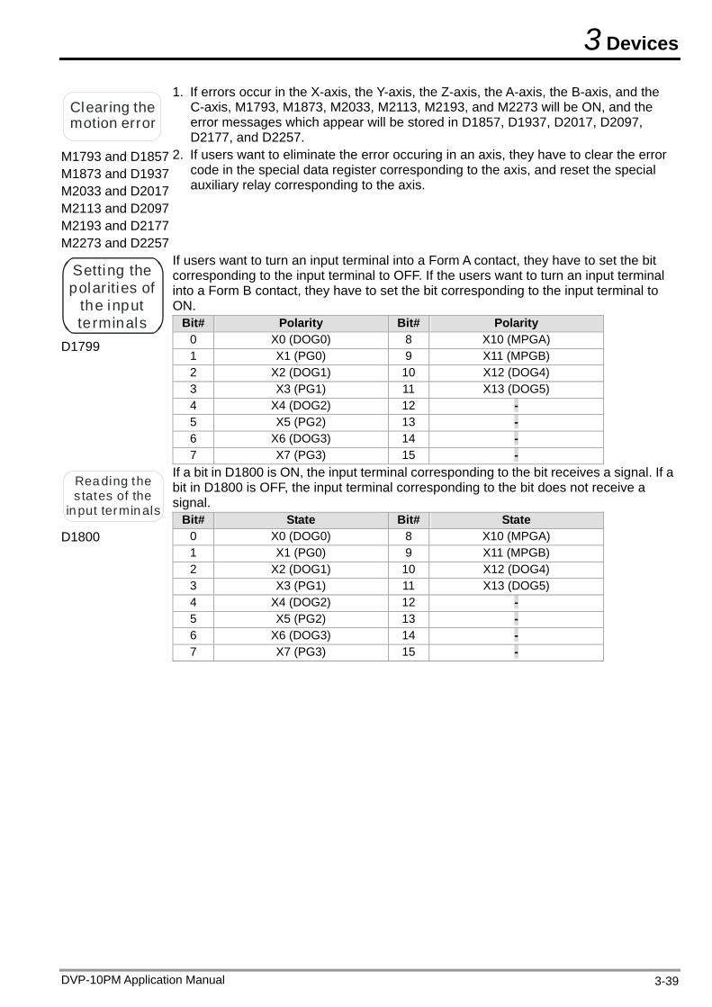
3 Devices
Clearing the motion error
1. If errors occur in the X-axis, the Y-axis, the Z-axis, the A-axis, the B-axis, and the C-axis, M1793, M1873, M2033, M2113, M2193, and M2273 will be ON, and the error messages which appear will be stored in D1857, D1937, D2017, D2097, D2177, and D2257.
M1793 and D1857 M1873 and D1937 M2033 and D2017 M2113 and D2097 M2193 and D2177 M2273 and D2257
2. If users want to eliminate the error occuring in an axis, they have to clear the error code in the special data register corresponding to the axis, and reset the special auxiliary relay corresponding to the axis.
Setting the polarities of
the input terminals
D1799
If users want to turn an input terminal into a Form A contact, they have to set the bit corresponding to the input terminal to OFF. If the users want to turn an input terminal into a Form B contact, they have to set the bit corresponding to the input terminal to ON.
Bit# Polarity Bit# Polarity 0 X0 (DOG0) 8 X10 (MPGA) 1 X1 (PG0) 9 X11 (MPGB) 2 X2 (DOG1) 10 X12 (DOG4) 3 X3 (PG1) 11 X13 (DOG5) 4 X4 (DOG2) 12 - 5 X5 (PG2) 13 - 6 X6 (DOG3) 14 - 7 X7 (PG3) 15 -
Reading the s tates of the
in put termin als
D1800
If a bit in D1800 is ON, the input terminal corresponding to the bit receives a signal. If a bit in D1800 is OFF, the input terminal corresponding to the bit does not receive a signal.
Bit# State Bit# State 0 X0 (DOG0) 8 X10 (MPGA) 1 X1 (PG0) 9 X11 (MPGB) 2 X2 (DOG1) 10 X12 (DOG4) 3 X3 (PG1) 11 X13 (DOG5) 4 X4 (DOG2) 12 - 5 X5 (PG2) 13 - 6 X6 (DOG3) 14 - 7 X7 (PG3) 15 -
DVP-10PM Application Manual 3-39
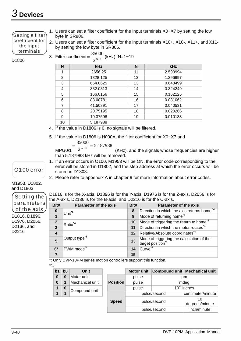
3 Devices
DVP-10PM Application Manual 3-40
Setting a fil ter coefficie
the inpterminals
nt for ut
D1806
1. Users can set a filter coefficient for the input terminals X0~X7 by setting the low byte in SR806.
2. Users can set a filter coefficient for the input terminals X10+, X10-, X11+, and X11-by setting the low byte in SR806.
3. Filter coefficeint4N2
85000 (kHz); N=1~19
N kHz N kHz 1 2656.25 11 2.593994 2 1328.125 12 1.296997 3 664.0625 13 0.648499 4 332.0313 14 0.324249 5 166.0156 15 0.162125 6 83.00781 16 0.081062 7 41.50391 17 0.040531 8 20.75195 18 0.020266 9 10.37598 19 0.010133 10 5.187988
4. If the value in D1806 is 0, no signals will be filtered.
5. If the value in D1806 is H000A, the filter coefficient for X0~X7 and
MPG0/15.187988
2
85000410
(KHz), and the signals whose frequencies are higher than 5.187988 kHz will be removed.
O100 er ror
M1953, D1802, and D1803
1. If an error occurs in O100, M1953 will be ON, the error code corresponding to the error will be stored in D1802, and the step address at which the error occurs will be stored in D1803.
2. Please refer to appendix A in chapter 9 for more information about error codes.
Se tt in g the paramete rs of the ax is
D1816, D1896, D1976, D2056, D2136, and D2216
D1816 is for the X-axis, D1896 is for the Y-axis, D1976 is for the Z-axis, D2056 is for the A-axis, D2136 is for the B-axis, and D2216 is for the C-axis.
Bit# Parameter of the axis Bit# Parameter of the axis 0 8 Direction in which the axis returns home *4
1 Unit*1
9 Mode of returning home*4 2 10 Mode of triggering the return to home*4 3
Ratio*4 11 Direction in which the motor rotates*4
4 12 Relative/Absolute coordinates*4
5 Output type*3
13 Mode of triggering the calculation of the target position*4
6* PWM mode*4 14 Curve*4 7 15
*: Only DVP-10PM series motion controllers support this function. *1:
b1 b0 Unit Motor unit Compound unit Mechanical unit0 0 Motor unit pulse µm 0 1 Mechanical unit pulse mdeg 1 0
Positionpulse 10-4 inches
1 1 Compound unit
pulse/second centimeter/minute
pulse/second 10 degrees/minute
Speed
pulse/second inch/minute
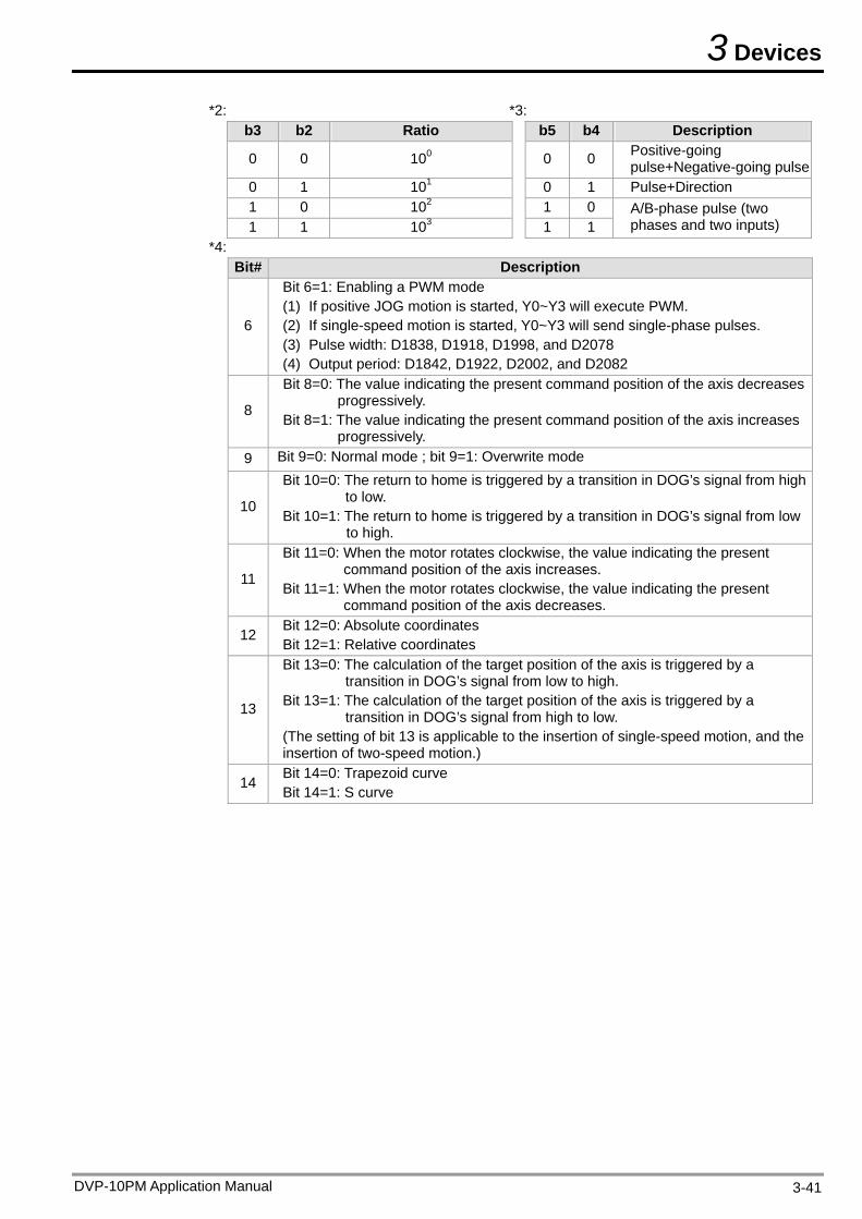
3 Devices
*2: *3: b3 b2 Ratio b5 b4 Description
0 0 100 0 0 Positive-going pulse+Negative-going pulse
0 1 101 0 1 Pulse+Direction 1 0 102 1 0 1 1 103 1 1
A/B-phase pulse (two phases and two inputs)
*4: Bit# Description
6
Bit 6=1: Enabling a PWM mode (1) If positive JOG motion is started, Y0~Y3 will execute PWM. (2) If single-speed motion is started, Y0~Y3 will send single-phase pulses. (3) Pulse width: D1838, D1918, D1998, and D2078 (4) Output period: D1842, D1922, D2002, and D2082
8
Bit 8=0: The value indicating the present command position of the axis decreases progressively.
Bit 8=1: The value indicating the present command position of the axis increases progressively.
9 Bit 9=0: Normal mode ; bit 9=1: Overwrite mode
10
Bit 10=0: The return to home is triggered by a transition in DOG’s signal from high to low.
Bit 10=1: The return to home is triggered by a transition in DOG’s signal from low to high.
11
Bit 11=0: When the motor rotates clockwise, the value indicating the present command position of the axis increases.
Bit 11=1: When the motor rotates clockwise, the value indicating the present command position of the axis decreases.
12 Bit 12=0: Absolute coordinates Bit 12=1: Relative coordinates
13
Bit 13=0: The calculation of the target position of the axis is triggered by a transition in DOG’s signal from low to high.
Bit 13=1: The calculation of the target position of the axis is triggered by a transition in DOG’s signal from high to low.
(The setting of bit 13 is applicable to the insertion of single-speed motion, and the insertion of two-speed motion.)
14 Bit 14=0: Trapezoid curve Bit 14=1: S curve
DVP-10PM Application Manual 3-41
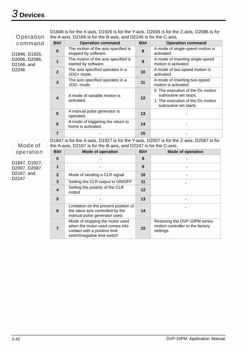
3 Devices
O pera tion command
D1846, D1926, D2006, D2086, D2166, and D2246
D1846 is for the X-axis, D1926 is for the Y-axis, D2006 is for the Z-axis, D2086 is for the A-axis, D2166 is for the B-axis, and D2246 is for the C-axis.
Bit# Operation command Bit# Operation command
0 The motion of the axis specified is stopped by software. 8 A mode of single-speed motion is
activated.
1 The motion of the axis specified is started by software. 9 A mode of inserting single-speed
motion is activated.
2 The axis specified operates in a JOG+ mode. 10 A mode of two-speed motion is
activated.
3 The axis specified operates in a JOG- mode. 11 A mode of inserting two-speed
motion is activated.
4 A mode of variable motion is activated. 12
0: The execution of the Ox motion subroutine set stops.
1: The execution of the Ox motion subroutine set starts.
5 A manual pulse generator is operated. 13 -
6 A mode of triggering the return to home is activated. 14 -
7 - 15 -
Mode of ope rat ion
D1847, D1927, D2007, D2087, D2167, and D2247
D1847 is for the X-axis, D1927 is for the Y-axis, D2007 is for the Z-axis, D2087 is for the A-axis, D2167 is for the B-axis, and D2247 is for the C-axis.
Bit# Mode of operation Bit# Mode of operation 0 - 8 -
1 - 9 -
2 Mode of sending a CLR signal 10 - 3 Setting the CLR output to ON/OFF 11
4 Setting the polarity of the CLR output 12
-
5 - 13 -
6 Limitation on the present position of the slave axis controlled by the manual pulse generator used
14 -
7 Mode of stopping the motor used when the motor used comes into contact with a positive limit switch/negative limit switch
15 Restoring the DVP-10PM series motion controller to the factory settings
DVP-10PM Application Manual 3-42
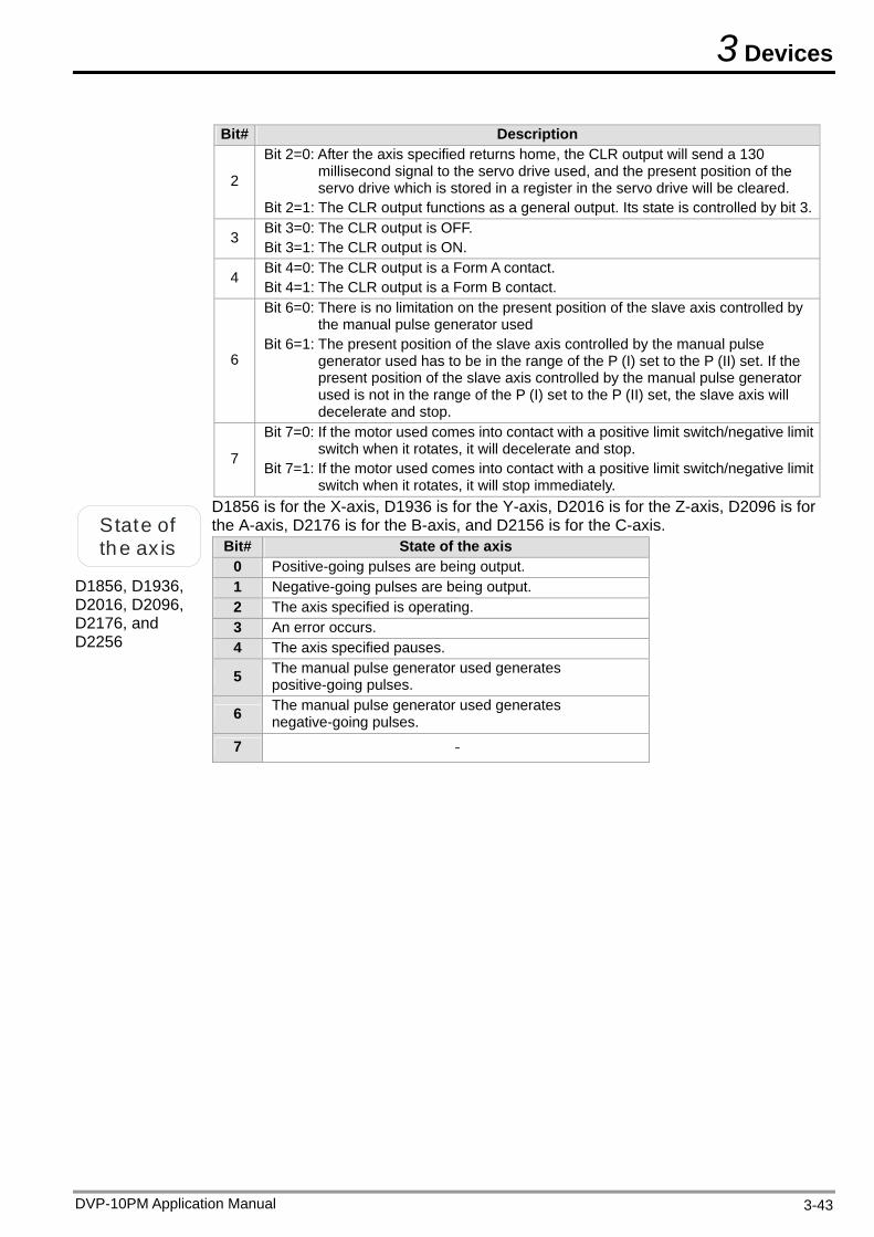
3 Devices
Bit# Description
2
Bit 2=0: After the axis specified returns home, the CLR output will send a 130 millisecond signal to the servo drive used, and the present position of the servo drive which is stored in a register in the servo drive will be cleared.
Bit 2=1: The CLR output functions as a general output. Its state is controlled by bit 3.
3 Bit 3=0: The CLR output is OFF. Bit 3=1: The CLR output is ON.
4 Bit 4=0: The CLR output is a Form A contact. Bit 4=1: The CLR output is a Form B contact.
6
Bit 6=0: There is no limitation on the present position of the slave axis controlled by the manual pulse generator used
Bit 6=1: The present position of the slave axis controlled by the manual pulse generator used has to be in the range of the P (I) set to the P (II) set. If the present position of the slave axis controlled by the manual pulse generator used is not in the range of the P (I) set to the P (II) set, the slave axis will decelerate and stop.
7
Bit 7=0: If the motor used comes into contact with a positive limit switch/negative limit switch when it rotates, it will decelerate and stop.
Bit 7=1: If the motor used comes into contact with a positive limit switch/negative limit switch when it rotates, it will stop immediately.
State of the ax is
D1856, D1936, D2016, D2096, D2176, and D2256
D1856 is for the X-axis, D1936 is for the Y-axis, D2016 is for the Z-axis, D2096 is for the A-axis, D2176 is for the B-axis, and D2156 is for the C-axis.
Bit# State of the axis 0 Positive-going pulses are being output. 1 Negative-going pulses are being output. 2 The axis specified is operating. 3 An error occurs. 4 The axis specified pauses.
5 The manual pulse generator used generates positive-going pulses.
6 The manual pulse generator used generates negative-going pulses.
7 -
DVP-10PM Application Manual 3-43
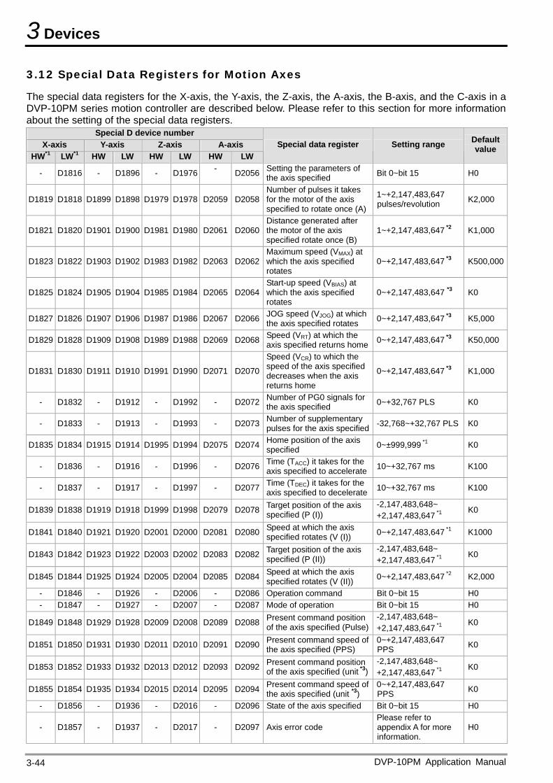
3 Devices
3.12 Special Data Registers for Motion Axes
The special data registers for the X-axis, the Y-axis, the Z-axis, the A-axis, the B-axis, and the C-axis in a DVP-10PM series motion controller are described below. Please refer to this section for more information about the setting of the special data registers.
Special D device number X-axis Y-axis Z-axis A-axis
HW*1 LW*1 HW LW HW LW HW LW Special data register Setting range Default
value
- D1816 - D1896 - D1976 - D2056 Setting the parameters of the axis specified Bit 0~bit 15 H0
D1819 D1818 D1899 D1898 D1979 D1978 D2059 D2058Number of pulses it takes for the motor of the axis specified to rotate once (A)
1~+2,147,483,647 pulses/revolution K2,000
D1821 D1820 D1901 D1900 D1981 D1980 D2061 D2060Distance generated after the motor of the axis specified rotate once (B)
1~+2,147,483,647 *2 K1,000
D1823 D1822 D1903 D1902 D1983 D1982 D2063 D2062Maximum speed (VMAX) at which the axis specified rotates
0~+2,147,483,647 *3 K500,000
D1825 D1824 D1905 D1904 D1985 D1984 D2065 D2064Start-up speed (VBIAS) at which the axis specified rotates
0~+2,147,483,647 *3 K0
D1827 D1826 D1907 D1906 D1987 D1986 D2067 D2066 JOG speed (VJOG) at which the axis specified rotates 0~+2,147,483,647 *3 K5,000
D1829 D1828 D1909 D1908 D1989 D1988 D2069 D2068 Speed (VRT) at which the axis specified returns home 0~+2,147,483,647 *3 K50,000
D1831 D1830 D1911 D1910 D1991 D1990 D2071 D2070
Speed (VCR) to which the speed of the axis specified decreases when the axis returns home
0~+2,147,483,647 *3 K1,000
- D1832 - D1912 - D1992 - D2072 Number of PG0 signals for the axis specified 0~+32,767 PLS K0
- D1833 - D1913 - D1993 - D2073 Number of supplementary pulses for the axis specified -32,768~+32,767 PLS K0
D1835 D1834 D1915 D1914 D1995 D1994 D2075 D2074 Home position of the axis specified 0~±999,999 *1 K0
- D1836 - D1916 - D1996 - D2076 Time (TACC) it takes for the axis specified to accelerate 10~+32,767 ms K100
- D1837 - D1917 - D1997 - D2077 Time (TDEC) it takes for the axis specified to decelerate 10~+32,767 ms K100
D1839 D1838 D1919 D1918 D1999 D1998 D2079 D2078 Target position of the axis specified (P (I))
-2,147,483,648~ +2,147,483,647 *1
K0
D1841 D1840 D1921 D1920 D2001 D2000 D2081 D2080 Speed at which the axis specified rotates (V (I)) 0~+2,147,483,647 *1 K1000
D1843 D1842 D1923 D1922 D2003 D2002 D2083 D2082 Target position of the axis specified (P (II))
-2,147,483,648~ +2,147,483,647 *1
K0
D1845 D1844 D1925 D1924 D2005 D2004 D2085 D2084 Speed at which the axis specified rotates (V (II)) 0~+2,147,483,647 *2 K2,000
- D1846 - D1926 - D2006 - D2086 Operation command Bit 0~bit 15 H0 - D1847 - D1927 - D2007 - D2087 Mode of operation Bit 0~bit 15 H0
D1849 D1848 D1929 D1928 D2009 D2008 D2089 D2088 Present command position of the axis specified (Pulse)
-2,147,483,648~ +2,147,483,647 *1
K0
D1851 D1850 D1931 D1930 D2011 D2010 D2091 D2090 Present command speed of the axis specified (PPS)
0~+2,147,483,647 PPS K0
D1853 D1852 D1933 D1932 D2013 D2012 D2093 D2092 Present command position of the axis specified (unit *3)
-2,147,483,648~ +2,147,483,647 *1
K0
D1855 D1854 D1935 D1934 D2015 D2014 D2095 D2094 Present command speed of the axis specified (unit *3)
0~+2,147,483,647 PPS K0
- D1856 - D1936 - D2016 - D2096 State of the axis specified Bit 0~bit 15 H0
- D1857 - D1937 - D2017 - D2097 Axis error code Please refer to appendix A for more information.
H0
DVP-10PM Application Manual 3-44
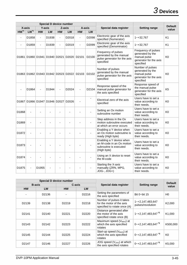
3 Devices
DVP-10PM Application Manual 3-45
Special D device number X-axis Y-axis Z-axis A-axis
HW*1 LW*1 HW LW HW LW HW LW Special data register Setting range Default
value
- D1858 - D1938 - D2018 - D2098 Electronic gear of the axis specified (Numerator) 1~+32,767 K1
- D1859 - D1939 - D2019 - D2099 Electronic gear of the axis specified (Denominator) 1~+32,767 K1
D1861 D1860 D1941 D1940 D2021 D2020 D2101 D2100
Frequency of pulses generated by the manual pulse generator for the axis specified
Frequency of pulses generated by the manual pulse generator for the axis specified
K0
D1863 D1862 D1943 D1942 D2023 D2022 D2103 D2102
Number of pulses generated by the manual pulse generator for the axis specified
Number of pulses generated by the manual pulse generator for the axis specified
K0
- D1864 - D1944 - D2024 - D2104Response speed of the manual pulse generator for the axis specified
Response speed of the manual pulse generator for the axis specified
K5
D1867 D1866 D1947 D1946 D2027 D2026 - - Electrical zero of the axis
specified
Users have to set a value according to their needs.
K0
D1868 - - - - - - - Setting an Ox motion subroutine number
Users have to set a value according to their needs.
K0
D1869 - - - - - - - Step address in the Ox motion subroutine executed at which an error occurs
Users have to set a value according to their needs.
K0
D1872 - - - - - - - Enabling a Y device when an Ox motion subroutine is ready (High byte)
Users have to set a value according to their needs.
K0
D1873 - - - - - - -
Enabling a Y device when an M-code in an Ox motion subroutine is executed (High byte)
Users have to set a value according to their needs.
K0
D1874 - - - - - - - Using an X device to reset the M-code
Users have to set a value according to their needs.
K0
D1875 - D1955 - - - - - Starting the X-axis manually (ZRN, MPG, JOG-, JOG+)
Users have to set a value according to their needs.
K0
Special D device number
B-axis C-axis HW LW HW LW
Special data register Setting range Default value
- D2136 - D2216 Setting the parameters of the axis specified Bit 0~bit 15 H0
D2139 D2138 D2219 D2218 Number of pulses it takes for the motor of the axis specified to rotate once (A)
1~+2,147,483,647 pulses/revolution K2,000
D2141 D2140 D2221 D2220 Distance generated after the motor of the axis specified rotate once (B)
1~+2,147,483,647 *2 K1,000
D2143 D2142 D2223 D2222 Maximum speed (VMAX) at which the axis specified rotates
0~+2,147,483,647 *3 K500,000
D2145 D2144 D2225 D2224 Start-up speed (VBIAS) at which the axis specified rotates
0~+2,147,483,647 *3 K0
D2147 D2146 D2227 D2226 JOG speed (VJOG) at which the axis specified rotates 0~+2,147,483,647 *3 K5,000
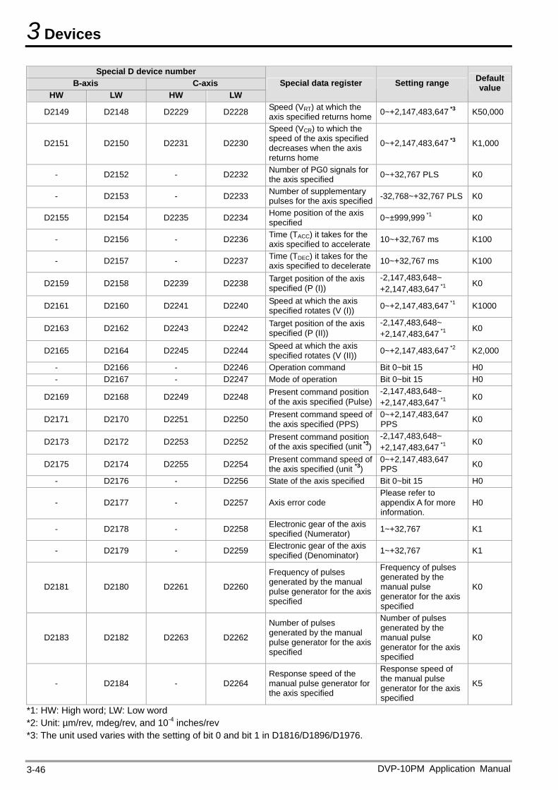
3 Devices
DVP-10PM Application Manual 3-46
Special D device number B-axis C-axis
HW LW HW LW Special data register Setting range Default
value
D2149 D2148 D2229 D2228 Speed (VRT) at which the axis specified returns home 0~+2,147,483,647 *3 K50,000
D2151 D2150 D2231 D2230
Speed (VCR) to which the speed of the axis specified decreases when the axis returns home
0~+2,147,483,647 *3 K1,000
- D2152 - D2232 Number of PG0 signals for the axis specified 0~+32,767 PLS K0
- D2153 - D2233 Number of supplementary pulses for the axis specified -32,768~+32,767 PLS K0
D2155 D2154 D2235 D2234 Home position of the axis specified 0~±999,999 *1 K0
- D2156 - D2236 Time (TACC) it takes for the axis specified to accelerate 10~+32,767 ms K100
- D2157 - D2237 Time (TDEC) it takes for the axis specified to decelerate 10~+32,767 ms K100
D2159 D2158 D2239 D2238 Target position of the axis specified (P (I))
-2,147,483,648~ +2,147,483,647 *1
K0
D2161 D2160 D2241 D2240 Speed at which the axis specified rotates (V (I)) 0~+2,147,483,647 *1 K1000
D2163 D2162 D2243 D2242 Target position of the axis specified (P (II))
-2,147,483,648~ +2,147,483,647 *1
K0
D2165 D2164 D2245 D2244 Speed at which the axis specified rotates (V (II)) 0~+2,147,483,647 *2 K2,000
- D2166 - D2246 Operation command Bit 0~bit 15 H0 - D2167 - D2247 Mode of operation Bit 0~bit 15 H0
D2169 D2168 D2249 D2248 Present command position of the axis specified (Pulse)
-2,147,483,648~ +2,147,483,647 *1
K0
D2171 D2170 D2251 D2250 Present command speed of the axis specified (PPS)
0~+2,147,483,647 PPS K0
D2173 D2172 D2253 D2252 Present command position of the axis specified (unit *3)
-2,147,483,648~ +2,147,483,647 *1
K0
D2175 D2174 D2255 D2254 Present command speed of the axis specified (unit *3)
0~+2,147,483,647 PPS K0
- D2176 - D2256 State of the axis specified Bit 0~bit 15 H0
- D2177 - D2257 Axis error code Please refer to appendix A for more information.
H0
- D2178 - D2258 Electronic gear of the axis specified (Numerator) 1~+32,767 K1
- D2179 - D2259 Electronic gear of the axis specified (Denominator) 1~+32,767 K1
D2181 D2180 D2261 D2260
Frequency of pulses generated by the manual pulse generator for the axis specified
Frequency of pulses generated by the manual pulse generator for the axis specified
K0
D2183 D2182 D2263 D2262
Number of pulses generated by the manual pulse generator for the axis specified
Number of pulses generated by the manual pulse generator for the axis specified
K0
- D2184 - D2264 Response speed of the manual pulse generator for the axis specified
Response speed of the manual pulse generator for the axis specified
K5
*1: HW: High word; LW: Low word *2: Unit: µm/rev, mdeg/rev, and 10-4 inches/rev *3: The unit used varies with the setting of bit 0 and bit 1 in D1816/D1896/D1976.
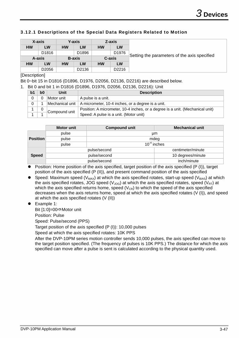
3 Devices
3.12.1 Descriptions of the Special Data Registers Related to Motion
X-axis Y-axis Z-axis HW LW HW LW HW LW
D1816 D1896 D1976A-axis B-axis C-axis
HW LW HW LW HW LW D2056 D2136 D2216
Setting the parameters of the axis specified
[Description] Bit 0~bit 15 in D1816 (D1896, D1976, D2056, D2136, D2216) are described below. 1. Bit 0 and bit 1 in D1816 (D1896, D1976, D2056, D2136, D2216): Unit
b1 b0 Unit Description 0 0 Motor unit A pulse is a unit. 0 1 Mechanical unit A micrometer, 10-4 inches, or a degree is a unit. 1 0 1 1
Compound unit Position: A micrometer, 10-4 inches, or a degree is a unit. (Mechanical unit) Speed: A pulse is a unit. (Motor unit)
Motor unit Compound unit Mechanical unit
pulse µm pulse mdeg Position pulse 10-4 inches
pulse/second centimeter/minute pulse/second 10 degrees/minute Speed pulse/second inch/minute
Position: Home position of the axis specified, target position of the axis specified (P (I)), target position of the axis specified (P (II)), and present command position of the axis specified
Speed: Maximum speed (VMAX) at which the axis specified rotates, start-up speed (VBIAS) at which the axis specified rotates, JOG speed (VJOG) at which the axis specified rotates, speed (VRT) at which the axis specified returns home, speed (VCR) to which the speed of the axis specified decreases when the axis returns home, speed at which the axis specified rotates (V (I)), and speed at which the axis specified rotates (V (II))
Example 1: Bit [1:0]=00Motor unit Position: Pulse Speed: Pulse/second (PPS) Target position of the axis specified (P (I)): 10,000 pulses Speed at which the axis specified rotates: 10K PPS After the DVP-10PM series motion controller sends 10,000 pulses, the axis specified can move to the target position specified. (The frequency of pulses is 10K PPS.) The distance for which the axis specified can move after a pulse is sent is calculated according to the physical quantity used.
DVP-10PM Application Manual 3-47
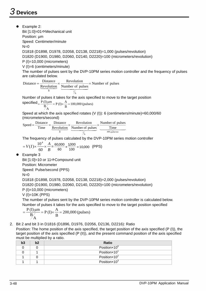
3 Devices
Example 2: Bit [1:0]=01Mechanical unit Position: µm Speed: Centimeter/minute N=0 D1818 (D1898, D1978, D2058, D2138, D2218)=1,000 (pulses/revolution) D1820 (D1900, D1980, D2060, D2140, D2220)=100 (micrometers/revolution) P (I)=10,000 (micrometers) V (I)=6 (centimeters/minute) The number of pulses sent by the DVP-10PM series motion controller and the frequency of pulses are calculated below.
pulsesofNumberpulsesofNumber
Revolution
Revolution
DistanceDistance
A1B
Number of pulses it takes for the axis specified to move to the target position specified (pulses) 100,000
B
A(I) P
ABμm (I) P
Speed at which the axis specified rotates (V (I)): 6 (centimeters/minute)=60,000/60 (micrometers/second)
pulse/secPPS,
A1B
Time
pulses ofNumber
pulses ofNumber
Revolution
Revolution
Distance
Time
DistanceSpeed
The frequency of pulses calculated by the DVP-10PM series motion controller
B
AIV
60
10)(
4
= 000,10=100000,1
×60000,60 (PPS)
Example 3 Bit [1:0]=10 or 11Compound unit Position: Micrometer Speed: Pulse/second (PPS) N=0 D1818 (D1898, D1978, D2058, D2138, D2218)=2,000 (pulses/revolution) D1820 (D1900, D1980, D2060, D2140, D2220)=100 (micrometers/revolution) P (I)=10,000 (micrometers) V (I)=10K (PPS) The number of pulses sent by the DVP-10PM series motion controller is calculated below. Number of pulses it takes for the axis specified to move to the target position specified
(pulses) 200,000B
A(I) P
ABμm (I) P
2. Bit 2 and bit 3 in D1816 (D1896, D1976, D2056, D2136, D2216): Ratio Position: The home position of the axis specified, the target position of the axis specified (P (I)), the target position of the axis specified (P (II)), and the present command position of the axis specified must be multiplied by a ratio.
b3 b2 Ratio 0 0 Position×100 0 1 Position×101 1 0 Position×102 1 1 Position×103
DVP-10PM Application Manual 3-48
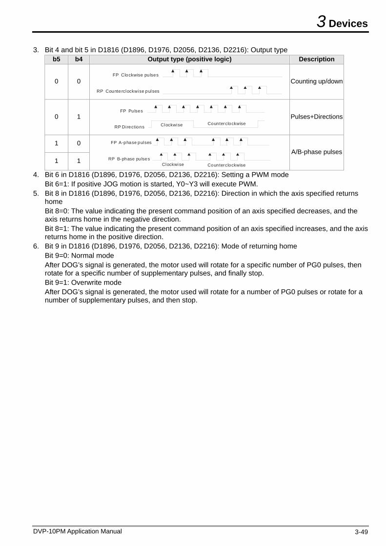
3 Devices
DVP-10PM Application Manual 3-49
3. Bit 4 and bit 5 in D1816 (D1896, D1976, D2056, D2136, D2216): Output type b5 b4 Output type (positive logic) Description
0 0 FP Clockwise pulses
RP Counterclockwise pulses
Counting up/down
0 1 FP Pulses
RP Directions Counterclockwise Clockwise
Pulses+Directions
1 0
1 1 Counterclockwise Clockwise
FP A-phase pulses
RP B-phase pulses
A/B-phase pulses
4. Bit 6 in D1816 (D1896, D1976, D2056, D2136, D2216): Setting a PWM mode Bit 6=1: If positive JOG motion is started, Y0~Y3 will execute PWM.
5. Bit 8 in D1816 (D1896, D1976, D2056, D2136, D2216): Direction in which the axis specified returns home Bit 8=0: The value indicating the present command position of an axis specified decreases, and the axis returns home in the negative direction. Bit 8=1: The value indicating the present command position of an axis specified increases, and the axis returns home in the positive direction.
6. Bit 9 in D1816 (D1896, D1976, D2056, D2136, D2216): Mode of returning home Bit 9=0: Normal mode After DOG’s signal is generated, the motor used will rotate for a specific number of PG0 pulses, then rotate for a specific number of supplementary pulses, and finally stop. Bit 9=1: Overwrite mode After DOG’s signal is generated, the motor used will rotate for a number of PG0 pulses or rotate for a number of supplementary pulses, and then stop.
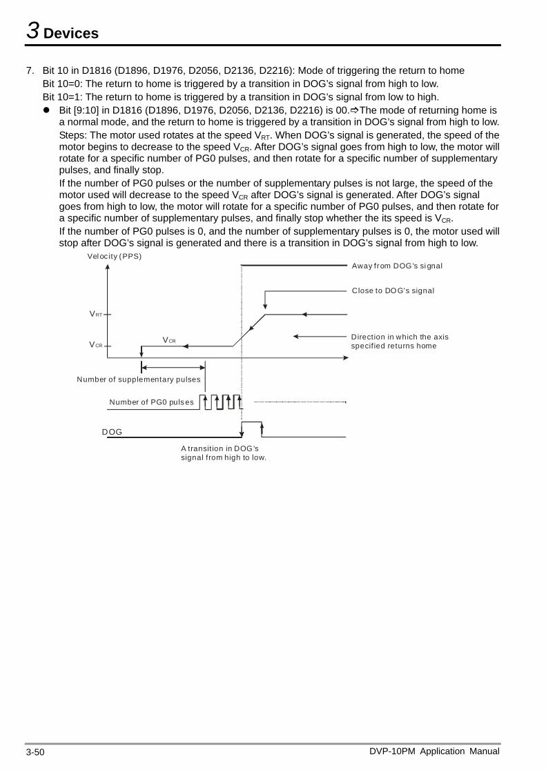
3 Devices
7. Bit 10 in D1816 (D1896, D1976, D2056, D2136, D2216): Mode of triggering the return to home Bit 10=0: The return to home is triggered by a transition in DOG’s signal from high to low. Bit 10=1: The return to home is triggered by a transition in DOG’s signal from low to high. Bit [9:10] in D1816 (D1896, D1976, D2056, D2136, D2216) is 00.The mode of returning home is
a normal mode, and the return to home is triggered by a transition in DOG’s signal from high to low. Steps: The motor used rotates at the speed VRT. When DOG’s signal is generated, the speed of the motor begins to decrease to the speed VCR. After DOG’s signal goes from high to low, the motor will rotate for a specific number of PG0 pulses, and then rotate for a specific number of supplementary pulses, and finally stop. If the number of PG0 pulses or the number of supplementary pulses is not large, the speed of the motor used will decrease to the speed VCR after DOG’s signal is generated. After DOG’s signal goes from high to low, the motor will rotate for a specific number of PG0 pulses, and then rotate for a specific number of supplementary pulses, and finally stop whether the its speed is VCR. If the number of PG0 pulses is 0, and the number of supplementary pulses is 0, the motor used will stop after DOG’s signal is generated and there is a transition in DOG’s signal from high to low.
DOG
Number of PG0 puls es
Number of supplementary pulses
VRT
VCR
Away from DOG's si gnal
Close to DOG's signal
Direction in which the axis specif ied returns home
VCR
A transit ion in DOG's signal from high to low.
Vel oc ity (PPS)
DVP-10PM Application Manual 3-50
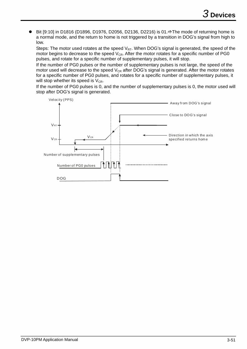
3 Devices
Bit [9:10] in D1816 (D1896, D1976, D2056, D2136, D2216) is 01.The mode of returning home is a normal mode, and the return to home is not triggered by a transition in DOG’s signal from high to low. Steps: The motor used rotates at the speed VRT. When DOG’s signal is generated, the speed of the motor begins to decrease to the speed VCR. After the motor rotates for a specific number of PG0 pulses, and rotate for a specific number of supplementary pulses, it will stop. If the number of PG0 pulses or the number of supplementary pulses is not large, the speed of the motor used will decrease to the speed VCR after DOG’s signal is generated. After the motor rotates for a specific number of PG0 pulses, and rotates for a specific number of supplementary pulses, it will stop whether its speed is VCR. If the number of PG0 pulses is 0, and the number of supplementary pulses is 0, the motor used will stop after DOG’s signal is generated.
Number of PG0 pulses
Number of supplementary pulses
Away from DOG's si gnal
Close to DOG's signal
Direction in which the axis specif ied returns hom e
Vel oc ity (PPS)
DOG
VRT
VCRVCR
DVP-10PM Application Manual 3-51
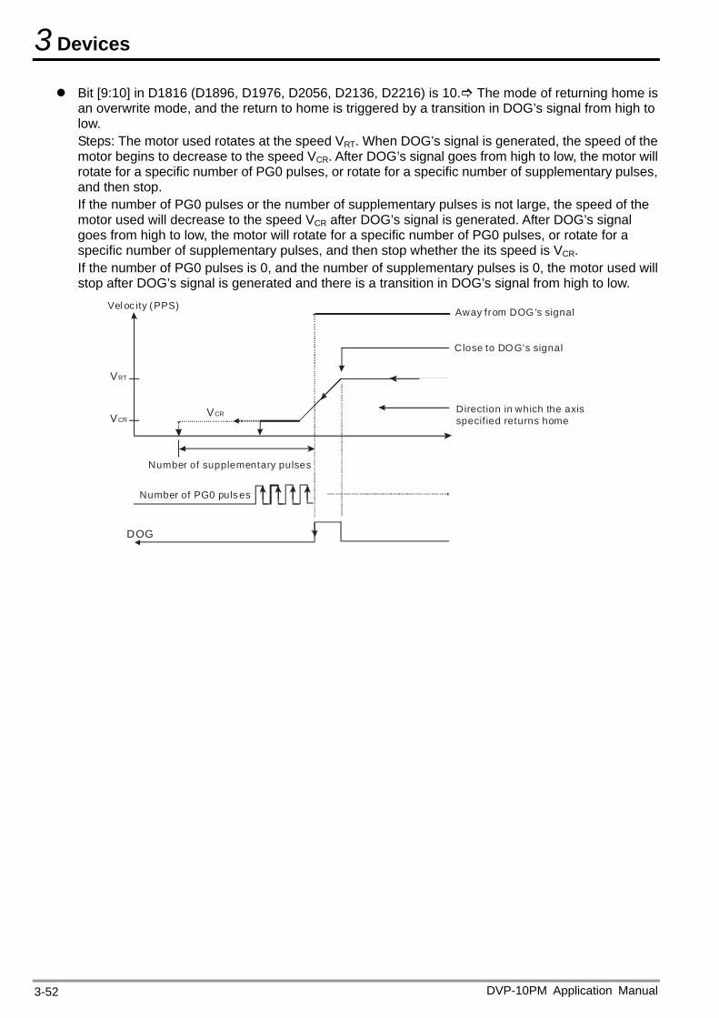
3 Devices
Bit [9:10] in D1816 (D1896, D1976, D2056, D2136, D2216) is 10. The mode of returning home is an overwrite mode, and the return to home is triggered by a transition in DOG’s signal from high to low. Steps: The motor used rotates at the speed VRT. When DOG’s signal is generated, the speed of the motor begins to decrease to the speed VCR. After DOG’s signal goes from high to low, the motor will rotate for a specific number of PG0 pulses, or rotate for a specific number of supplementary pulses, and then stop. If the number of PG0 pulses or the number of supplementary pulses is not large, the speed of the motor used will decrease to the speed VCR after DOG’s signal is generated. After DOG’s signal goes from high to low, the motor will rotate for a specific number of PG0 pulses, or rotate for a specific number of supplementary pulses, and then stop whether the its speed is VCR. If the number of PG0 pulses is 0, and the number of supplementary pulses is 0, the motor used will stop after DOG’s signal is generated and there is a transition in DOG’s signal from high to low.
Number of PG0 puls es
Number of supplementary pulses
Away from DOG's signal
Close to DOG's signal
Direction in which the axis specif ied returns home
Vel oc ity (PPS)
DOG
VCRVCR
VRT
DVP-10PM Application Manual 3-52
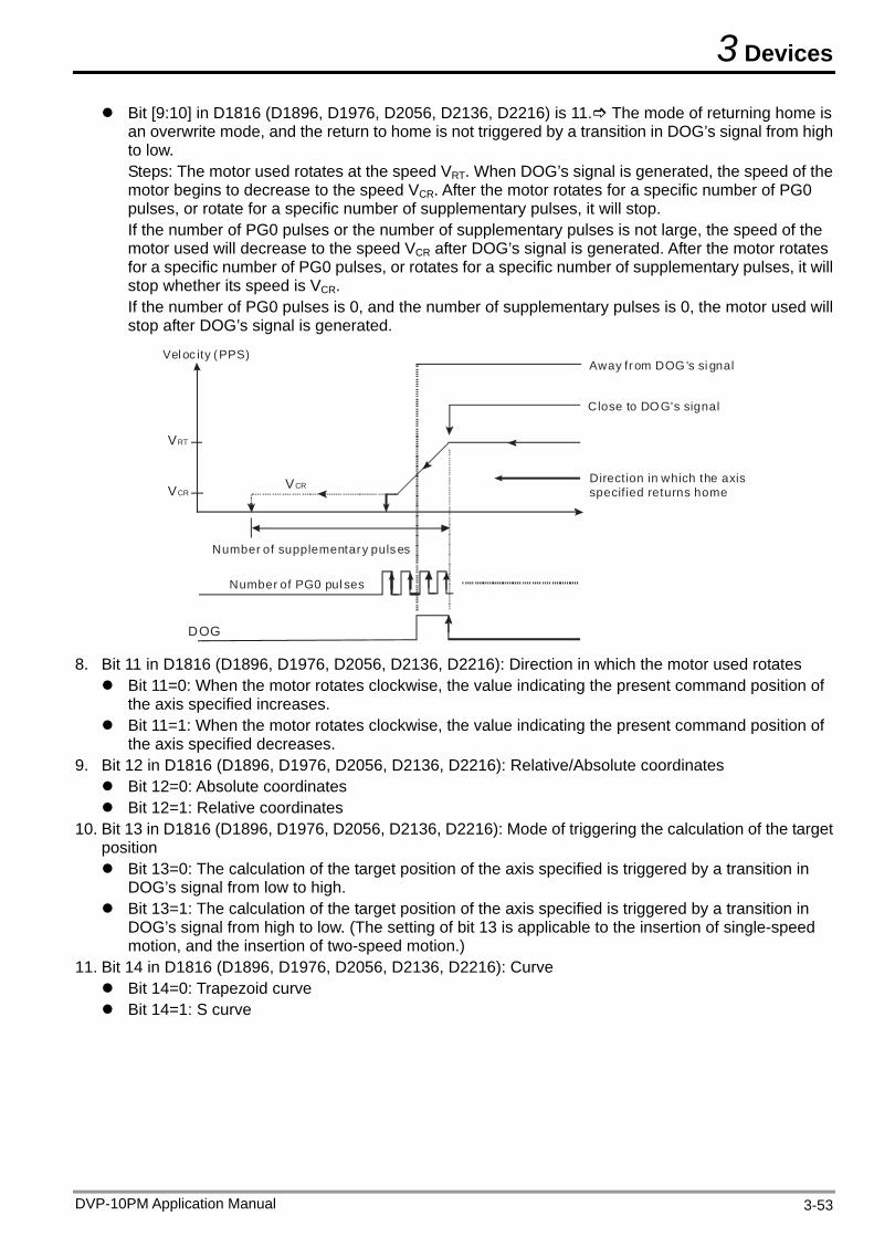
3 Devices
Bit [9:10] in D1816 (D1896, D1976, D2056, D2136, D2216) is 11. The mode of returning home is an overwrite mode, and the return to home is not triggered by a transition in DOG’s signal from high to low. Steps: The motor used rotates at the speed VRT. When DOG’s signal is generated, the speed of the motor begins to decrease to the speed VCR. After the motor rotates for a specific number of PG0 pulses, or rotate for a specific number of supplementary pulses, it will stop. If the number of PG0 pulses or the number of supplementary pulses is not large, the speed of the motor used will decrease to the speed VCR after DOG’s signal is generated. After the motor rotates for a specific number of PG0 pulses, or rotates for a specific number of supplementary pulses, it will stop whether its speed is VCR. If the number of PG0 pulses is 0, and the number of supplementary pulses is 0, the motor used will stop after DOG’s signal is generated.
Number of PG0 pul ses
Number of supplementary pulses
Away from DOG's si gnal
Close to DOG's signal
Direction in which the axis specif ied returns home
Vel oc ity (PPS)
DOG
VCRVCR
VRT
8. Bit 11 in D1816 (D1896, D1976, D2056, D2136, D2216): Direction in which the motor used rotates Bit 11=0: When the motor rotates clockwise, the value indicating the present command position of
the axis specified increases. Bit 11=1: When the motor rotates clockwise, the value indicating the present command position of
the axis specified decreases. 9. Bit 12 in D1816 (D1896, D1976, D2056, D2136, D2216): Relative/Absolute coordinates Bit 12=0: Absolute coordinates Bit 12=1: Relative coordinates
10. Bit 13 in D1816 (D1896, D1976, D2056, D2136, D2216): Mode of triggering the calculation of the target position Bit 13=0: The calculation of the target position of the axis specified is triggered by a transition in
DOG’s signal from low to high. Bit 13=1: The calculation of the target position of the axis specified is triggered by a transition in
DOG’s signal from high to low. (The setting of bit 13 is applicable to the insertion of single-speed motion, and the insertion of two-speed motion.)
11. Bit 14 in D1816 (D1896, D1976, D2056, D2136, D2216): Curve Bit 14=0: Trapezoid curve Bit 14=1: S curve
DVP-10PM Application Manual 3-53
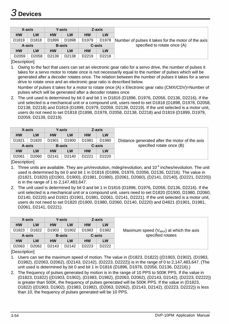
3 Devices
X-axis Y-axis Z-axis HW LW HW LW HW LW
D1819 D1818 D1899 D1898 D1979 D1978A-axis B-axis C-axis
HW LW HW LW HW LW D2059 D2058 D2139 D2138 D2219 D2218
Number of pulses it takes for the motor of the axis specified to rotate once (A)
[Description] 1. Owing to the fact that users can set an electronic gear ratio for a servo drive, the number of pulses it
takes for a servo motor to rotate once is not necessarily equal to the number of pulses which will be generated after a decoder rotates once. The relation between the number of pulses it takes for a servo drive to rotate once and an electronic gear ratio is described below. Number of pulses it takes for a motor to rotate once (A) x Electronic gear ratio (CMX/CDV)=Number of pulses which will be generated after a decoder rotates once
2. The unit used is determined by bit 0 and bit 1 in D1816 (D1896, D1976, D2056, D2136, D2216). If the unit selected is a mechanical unit or a compound unit, users need to set D1818 (D1898, D1978, D2058, D2138, D2218) and D1819 (D1899, D1979, D2059, D2139, D2219). If the unit selected is a motor unit, users do not need to set D1818 (D1898, D1978, D2058, D2138, D2218) and D1819 (D1899, D1979, D2059, D2139, D2219).
X-axis Y-axis Z-axis
HW LW HW LW HW LW D1821 D1820 D1901 D1900 D1981 D1980
A-axis B-axis C-axis HW LW HW LW HW LW
D2061 D2060 D2141 D2140 D2221 D2220
Distance generated after the motor of the axis specified rotate once (B)
[Description] 1. Three units are available. They are µm/revolution, mdeg/revolution, and 10-4 inches/revolution. The unit
used is determined by bit 0 and bit 1 in D1816 (D1896, D1976, D2056, D2136, D2216). The value in (D1821, D1820) ((D1901, D1900), (D1981, D1980), (D2061, D2060), (D2141, D2140), (D2221, D2220)) is in the range of 1 to 2,147,483,647.
2. The unit used is determined by bit 0 and bit 1 in D1816 (D1896, D1976, D2056, D2136, D2216). If the unit selected is a mechanical unit or a compound unit, users need to set D1820 (D1900, D1980, D2060, D2140, D2220) and D1821 (D1901, D1981, D2061, D2141, D2221). If the unit selected is a motor unit, users do not need to set D1820 (D1900, D1980, D2060, D2140, D2220) and D4821 (D1901, D1981, D2061, D2141, D2221).
X-axis Y-axis Z-axis
HW LW HW LW HW LW D1823 D1822 D1903 D1902 D1983 D1982
A-axis B-axis C-axis HW LW HW LW HW LW
D2063 D2062 D2143 D2142 D2223 D2222
Maximum speed (VMAX) at which the axis specified rotates
[Description] 1. Users can set the maximum speed of motion. The value in (D1823, D1822) ((D1903, D1902), (D1983,
D1982), (D2063, D2062), (D2143, D2142), (D2223, D2222)) is in the range of 0 to 2,147,483,647. (The unit used is determined by bit 0 and bit 1 in D1816 (D1896, D1976, D2056, D2136, D2216).)
2. The frequency of pulses generated by motion is in the range of 10 PPS to 500K PPS. If the value in (D1823, D1822) ((D1903, D1902), (D1983, D1982), (D2063, D2062), (D2143, D2142), (D2223, D2222)) is greater than 500K, the frequency of pulses generated will be 500K PPS. If the value in (D1823, D1822) ((D1903, D1902), (D1983, D1982), (D2063, D2062), (D2143, D2142), (D2223, D2222)) is less than 10, the frequency of pulses generated will be 10 PPS.
DVP-10PM Application Manual 3-54
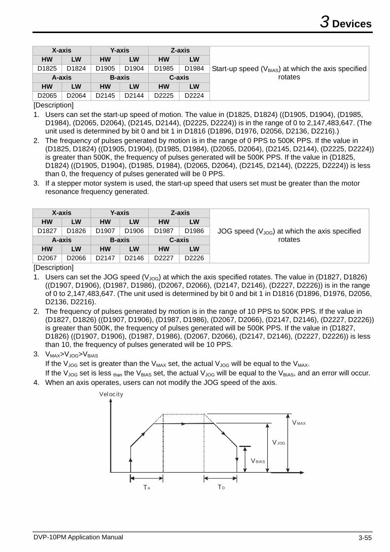
3 Devices
X-axis Y-axis Z-axis HW LW HW LW HW LW
D1825 D1824 D1905 D1904 D1985 D1984A-axis B-axis C-axis
HW LW HW LW HW LW D2065 D2064 D2145 D2144 D2225 D2224
Start-up speed (VBIAS) at which the axis specified rotates
[Description] 1. Users can set the start-up speed of motion. The value in (D1825, D1824) ((D1905, D1904), (D1985,
D1984), (D2065, D2064), (D2145, D2144), (D2225, D2224)) is in the range of 0 to 2,147,483,647. (The unit used is determined by bit 0 and bit 1 in D1816 (D1896, D1976, D2056, D2136, D2216).)
2. The frequency of pulses generated by motion is in the range of 0 PPS to 500K PPS. If the value in (D1825, D1824) ((D1905, D1904), (D1985, D1984), (D2065, D2064), (D2145, D2144), (D2225, D2224)) is greater than 500K, the frequency of pulses generated will be 500K PPS. If the value in (D1825, D1824) ((D1905, D1904), (D1985, D1984), (D2065, D2064), (D2145, D2144), (D2225, D2224)) is less than 0, the frequency of pulses generated will be 0 PPS.
3. If a stepper motor system is used, the start-up speed that users set must be greater than the motor resonance frequency generated.
X-axis Y-axis Z-axis
HW LW HW LW HW LW D1827 D1826 D1907 D1906 D1987 D1986
A-axis B-axis C-axis HW LW HW LW HW LW
D2067 D2066 D2147 D2146 D2227 D2226
JOG speed (VJOG) at which the axis specified rotates
[Description] 1. Users can set the JOG speed (VJOG) at which the axis specified rotates. The value in (D1827, D1826)
((D1907, D1906), (D1987, D1986), (D2067, D2066), (D2147, D2146), (D2227, D2226)) is in the range of 0 to 2,147,483,647. (The unit used is determined by bit 0 and bit 1 in D1816 (D1896, D1976, D2056, D2136, D2216).
2. The frequency of pulses generated by motion is in the range of 10 PPS to 500K PPS. If the value in (D1827, D1826) ((D1907, D1906), (D1987, D1986), (D2067, D2066), (D2147, D2146), (D2227, D2226)) is greater than 500K, the frequency of pulses generated will be 500K PPS. If the value in (D1827, D1826) ((D1907, D1906), (D1987, D1986), (D2067, D2066), (D2147, D2146), (D2227, D2226)) is less than 10, the frequency of pulses generated will be 10 PPS.
3. VMAX>VJOG>VBIAS If the VJOG set is greater than the VMAX set, the actual VJOG will be equal to the VMAX. If the VJOG set is less than the VBIAS set, the actual VJOG will be equal to the VBIAS, and an error will occur.
4. When an axis operates, users can not modify the JOG speed of the axis.
VBIAS
VJOG
VMAX
Veloc ity
TA TD
DVP-10PM Application Manual 3-55
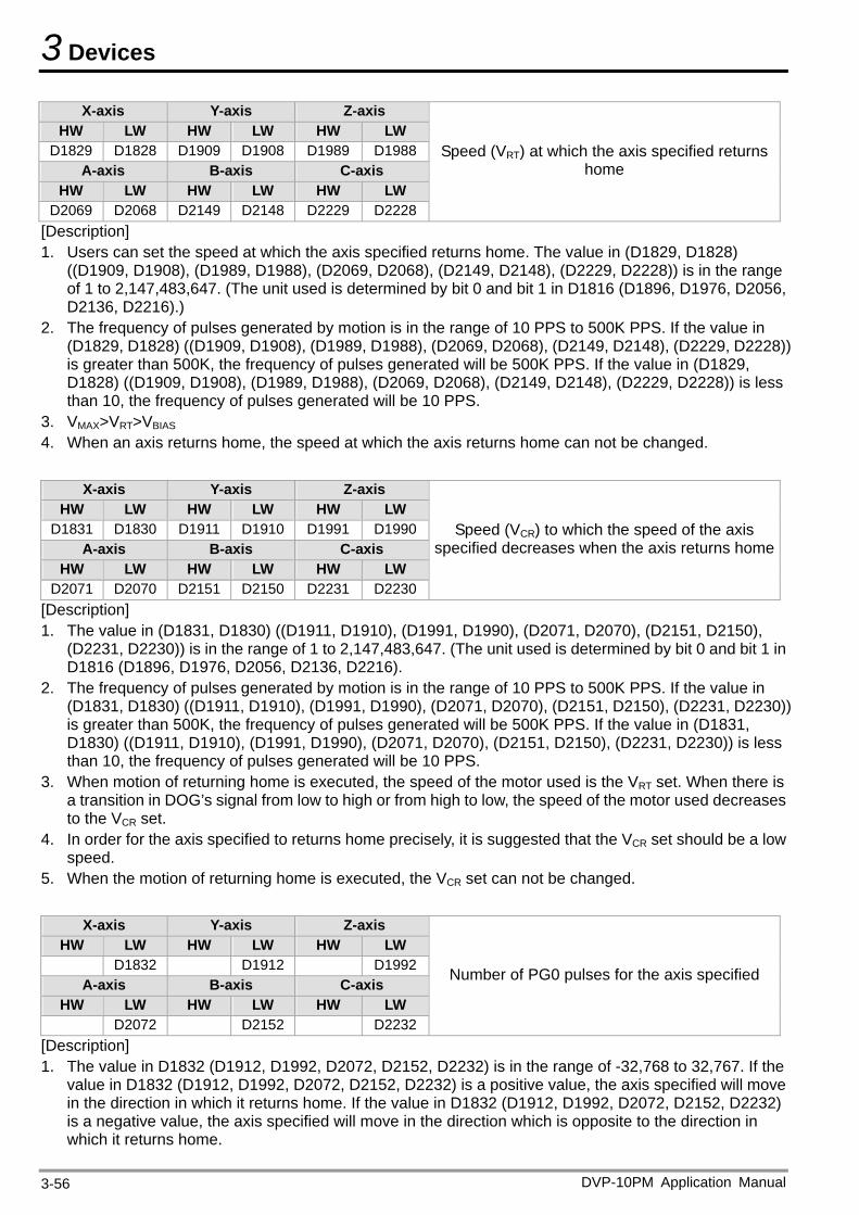
3 Devices
X-axis Y-axis Z-axis HW LW HW LW HW LW
D1829 D1828 D1909 D1908 D1989 D1988A-axis B-axis C-axis
HW LW HW LW HW LW D2069 D2068 D2149 D2148 D2229 D2228
Speed (VRT) at which the axis specified returns home
[Description] 1. Users can set the speed at which the axis specified returns home. The value in (D1829, D1828)
((D1909, D1908), (D1989, D1988), (D2069, D2068), (D2149, D2148), (D2229, D2228)) is in the range of 1 to 2,147,483,647. (The unit used is determined by bit 0 and bit 1 in D1816 (D1896, D1976, D2056, D2136, D2216).)
2. The frequency of pulses generated by motion is in the range of 10 PPS to 500K PPS. If the value in (D1829, D1828) ((D1909, D1908), (D1989, D1988), (D2069, D2068), (D2149, D2148), (D2229, D2228)) is greater than 500K, the frequency of pulses generated will be 500K PPS. If the value in (D1829, D1828) ((D1909, D1908), (D1989, D1988), (D2069, D2068), (D2149, D2148), (D2229, D2228)) is less than 10, the frequency of pulses generated will be 10 PPS.
3. VMAX>VRT>VBIAS 4. When an axis returns home, the speed at which the axis returns home can not be changed.
X-axis Y-axis Z-axis
HW LW HW LW HW LW D1831 D1830 D1911 D1910 D1991 D1990
A-axis B-axis C-axis HW LW HW LW HW LW
D2071 D2070 D2151 D2150 D2231 D2230
Speed (VCR) to which the speed of the axis specified decreases when the axis returns home
[Description] 1. The value in (D1831, D1830) ((D1911, D1910), (D1991, D1990), (D2071, D2070), (D2151, D2150),
(D2231, D2230)) is in the range of 1 to 2,147,483,647. (The unit used is determined by bit 0 and bit 1 in D1816 (D1896, D1976, D2056, D2136, D2216).
2. The frequency of pulses generated by motion is in the range of 10 PPS to 500K PPS. If the value in (D1831, D1830) ((D1911, D1910), (D1991, D1990), (D2071, D2070), (D2151, D2150), (D2231, D2230)) is greater than 500K, the frequency of pulses generated will be 500K PPS. If the value in (D1831, D1830) ((D1911, D1910), (D1991, D1990), (D2071, D2070), (D2151, D2150), (D2231, D2230)) is less than 10, the frequency of pulses generated will be 10 PPS.
3. When motion of returning home is executed, the speed of the motor used is the VRT set. When there is a transition in DOG’s signal from low to high or from high to low, the speed of the motor used decreases to the VCR set.
4. In order for the axis specified to returns home precisely, it is suggested that the VCR set should be a low speed.
5. When the motion of returning home is executed, the VCR set can not be changed.
X-axis Y-axis Z-axis HW LW HW LW HW LW
D1832 D1912 D1992A-axis B-axis C-axis
HW LW HW LW HW LW D2072 D2152 D2232
Number of PG0 pulses for the axis specified
[Description] 1. The value in D1832 (D1912, D1992, D2072, D2152, D2232) is in the range of -32,768 to 32,767. If the
value in D1832 (D1912, D1992, D2072, D2152, D2232) is a positive value, the axis specified will move in the direction in which it returns home. If the value in D1832 (D1912, D1992, D2072, D2152, D2232) is a negative value, the axis specified will move in the direction which is opposite to the direction in which it returns home.
DVP-10PM Application Manual 3-56
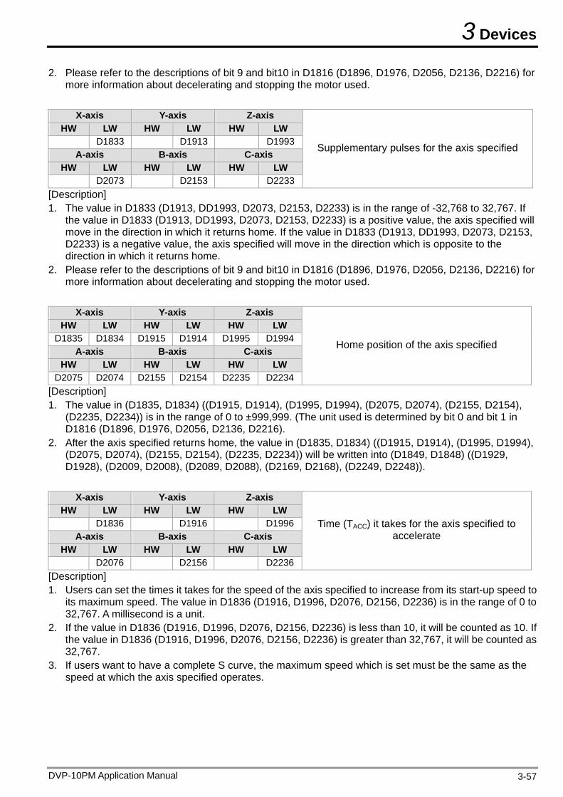
3 Devices
2. Please refer to the descriptions of bit 9 and bit10 in D1816 (D1896, D1976, D2056, D2136, D2216) for more information about decelerating and stopping the motor used.
X-axis Y-axis Z-axis
HW LW HW LW HW LW D1833 D1913 D1993
A-axis B-axis C-axis HW LW HW LW HW LW
D2073 D2153 D2233
Supplementary pulses for the axis specified
[Description] 1. The value in D1833 (D1913, DD1993, D2073, D2153, D2233) is in the range of -32,768 to 32,767. If
the value in D1833 (D1913, DD1993, D2073, D2153, D2233) is a positive value, the axis specified will move in the direction in which it returns home. If the value in D1833 (D1913, DD1993, D2073, D2153, D2233) is a negative value, the axis specified will move in the direction which is opposite to the direction in which it returns home.
2. Please refer to the descriptions of bit 9 and bit10 in D1816 (D1896, D1976, D2056, D2136, D2216) for more information about decelerating and stopping the motor used.
X-axis Y-axis Z-axis
HW LW HW LW HW LW D1835 D1834 D1915 D1914 D1995 D1994
A-axis B-axis C-axis HW LW HW LW HW LW
D2075 D2074 D2155 D2154 D2235 D2234
Home position of the axis specified
[Description] 1. The value in (D1835, D1834) ((D1915, D1914), (D1995, D1994), (D2075, D2074), (D2155, D2154),
(D2235, D2234)) is in the range of 0 to ±999,999. (The unit used is determined by bit 0 and bit 1 in D1816 (D1896, D1976, D2056, D2136, D2216).
2. After the axis specified returns home, the value in (D1835, D1834) ((D1915, D1914), (D1995, D1994), (D2075, D2074), (D2155, D2154), (D2235, D2234)) will be written into (D1849, D1848) ((D1929, D1928), (D2009, D2008), (D2089, D2088), (D2169, D2168), (D2249, D2248)).
X-axis Y-axis Z-axis
HW LW HW LW HW LW D1836 D1916 D1996
A-axis B-axis C-axis HW LW HW LW HW LW
D2076 D2156 D2236
Time (TACC) it takes for the axis specified to accelerate
[Description] 1. Users can set the times it takes for the speed of the axis specified to increase from its start-up speed to
its maximum speed. The value in D1836 (D1916, D1996, D2076, D2156, D2236) is in the range of 0 to 32,767. A millisecond is a unit.
2. If the value in D1836 (D1916, D1996, D2076, D2156, D2236) is less than 10, it will be counted as 10. If the value in D1836 (D1916, D1996, D2076, D2156, D2236) is greater than 32,767, it will be counted as 32,767.
3. If users want to have a complete S curve, the maximum speed which is set must be the same as the speed at which the axis specified operates.
DVP-10PM Application Manual 3-57
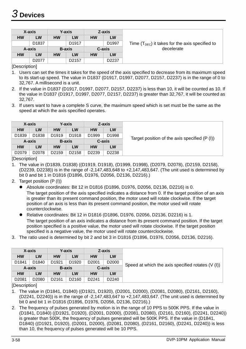
3 Devices
X-axis Y-axis Z-axis HW LW HW LW HW LW
D1837 D1917 D1997A-axis B-axis C-axis
HW LW HW LW HW LW D2077 D2157 D2237
Time (TDEC) it takes for the axis specified to decelerate
[Description] 1. Users can set the times it takes for the speed of the axis specified to decrease from its maximum speed
to its start-up speed. The value in D1837 (D1917, D1997, D2077, D2157, D2237) is in the range of 0 to 32,767. A millisecond is a unit.
2. If the value in D1837 (D1917, D1997, D2077, D2157, D2237) is less than 10, it will be counted as 10. If the value in D1837 (D1917, D1997, D2077, D2157, D2237) is greater than 32,767, it will be counted as 32,767.
3. If users want to have a complete S curve, the maximum speed which is set must be the same as the speed at which the axis specified operates.
X-axis Y-axis Z-axis
HW LW HW LW HW LW D1839 D1838 D1919 D1918 D1999 D1998
A-axis B-axis C-axis HW LW HW LW HW LW
D2079 D2078 D2159 D2158 D2239 D2238
Target position of the axis specified (P (I))
[Description] 1. The value in (D1839, D1838) ((D1919, D1918), (D1999, D1998), (D2079, D2078), (D2159, D2158),
(D2239, D2238)) is in the range of -2,147,483,648 to +2,147,483,647. (The unit used is determined by bit 0 and bit 1 in D1816 (D1896, D1976, D2056, D2136, D2216).)
2. Target position (P (I)) Absolute coordinates: Bit 12 in D1816 (D1896, D1976, D2056, D2136, D2216) is 0.
The target position of the axis specified indicates a distance from 0. If the target position of an axis is greater than its present command position, the motor used will rotate clockwise. If the target position of an axis is less than its present command position, the motor used will rotate counterclockwise.
Relative coordinates: Bit 12 in D1816 (D1896, D1976, D2056, D2136, D2216) is 1. The target position of an axis indicates a distance from its present command position. If the target position specified is a positive value, the motor used will rotate clockwise. If the target position specified is a negative value, the motor used will rotate counterclockwise.
3. The ratio used is determined by bit 2 and bit 3 in D1816 (D1896, D1976, D2056, D2136, D2216).
X-axis Y-axis Z-axis HW LW HW LW HW LW
D1841 D1840 D1921 D1920 D2001 D2000A-axis B-axis C-axis
HW LW HW LW HW LW D2081 D2080 D2161 D2160 D2241 D2240
Speed at which the axis specified rotates (V (I))
[Description] 1. The value in (D1841, D1840) ((D1921, D1920), (D2001, D2000), (D2081, D2080), (D2161, D2160),
(D2241, D2240)) is in the range of -2,147,483,647 to +2,147,483,647. (The unit used is determined by bit 0 and bit 1 in D1816 (D1896, D1976, D2056, D2136, D2216).)
2. The frequency of pulses generated by motion is in the range of 10 PPS to 500K PPS. If the value in (D1841, D1840) ((D1921, D1920), (D2001, D2000), (D2081, D2080), (D2161, D2160), (D2241, D2240)) is greater than 500K, the frequency of pulses generated will be 500K PPS. If the value in (D1841, D1840) ((D1921, D1920), (D2001, D2000), (D2081, D2080), (D2161, D2160), (D2241, D2240)) is less than 10, the frequency of pulses generated will be 10 PPS.
DVP-10PM Application Manual 3-58
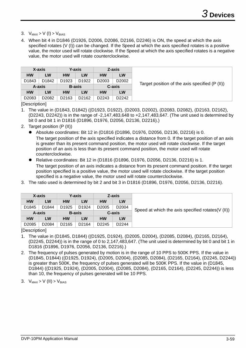
3 Devices
3. VMAX>V (I)>VBIAS 4. When bit 4 in D1846 (D1926, D2006, D2086, D2166, D2246) is ON, the speed at which the axis
specified rotates (V (I)) can be changed. If the Speed at which the axis specified rotates is a positive value, the motor used will rotate clockwise. If the Speed at which the axis specified rotates is a negative value, the motor used will rotate counterclockwise.
X-axis Y-axis Z-axis
HW LW HW LW HW LW D1843 D1842 D1923 D1922 D2003 D2002
A-axis B-axis C-axis HW LW HW LW HW LW
D2083 D2082 D2163 D2162 D2243 D2242
Target position of the axis specified (P (II))
[Description] 1. The value in (D1843, D1842) ((D1923, D1922), (D2003, D2002), (D2083, D2082), (D2163, D2162),
(D2243, D2242)) is in the range of -2,147,483,648 to +2,147,483,647. (The unit used is determined by bit 0 and bit 1 in D1816 (D1896, D1976, D2056, D2136, D2216).)
2. Target position (P (II)) Absolute coordinates: Bit 12 in (D1816 (D1896, D1976, D2056, D2136, D2216) is 0.
The target position of the axis specified indicates a distance from 0. If the target position of an axis is greater than its present command position, the motor used will rotate clockwise. If the target position of an axis is less than its present command position, the motor used will rotate counterclockwise.
Relative coordinates: Bit 12 in (D1816 (D1896, D1976, D2056, D2136, D2216) is 1. The target position of an axis indicates a distance from its present command position. If the target position specified is a positive value, the motor used will rotate clockwise. If the target position specified is a negative value, the motor used will rotate counterclockwise.
3. The ratio used is determined by bit 2 and bit 3 in D1816 (D1896, D1976, D2056, D2136, D2216).
X-axis Y-axis Z-axis HW LW HW LW HW LW
D1845 D1844 D1925 D1924 D2005 D2004A-axis B-axis C-axis
HW LW HW LW HW LW D2085 D2084 D2165 D2164 D2245 D2244
Speed at which the axis specified rotates(V (II))
[Description] 1. The value in (D1845, D1844) ((D1925, D1924), (D2005, D2004), (D2085, D2084), (D2165, D2164),
(D2245, D2244)) is in the range of 0 to 2,147,483,647. (The unit used is determined by bit 0 and bit 1 in D1816 (D1896, D1976, D2056, D2136, D2216).)
2. The frequency of pulses generated by motion is in the range of 10 PPS to 500K PPS. If the value in (D1845, D1844) ((D1925, D1924), (D2005, D2004), (D2085, D2084), (D2165, D2164), (D2245, D2244)) is greater than 500K, the frequency of pulses generated will be 500K PPS. If the value in (D1845, D1844) ((D1925, D1924), (D2005, D2004), (D2085, D2084), (D2165, D2164), (D2245, D2244)) is less than 10, the frequency of pulses generated will be 10 PPS.
3. VMAX>V (II)>VBIAS
DVP-10PM Application Manual 3-59
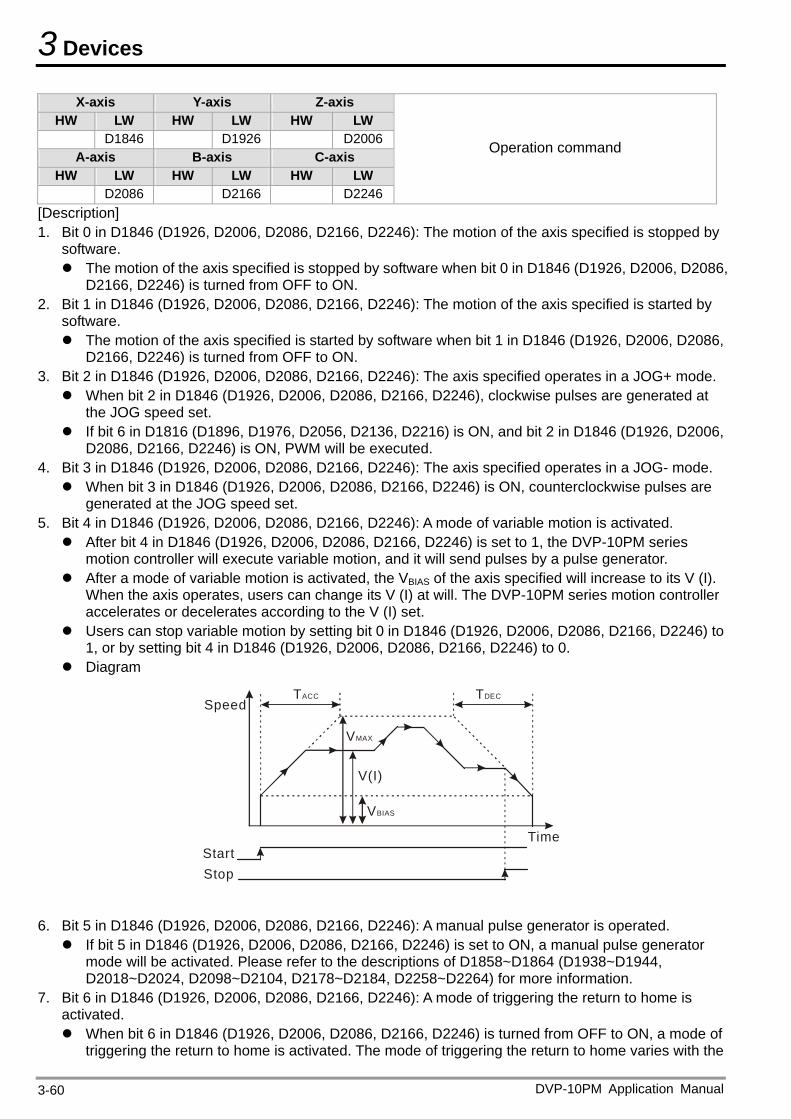
3 Devices
X-axis Y-axis Z-axis HW LW HW LW HW LW
D1846 D1926 D2006A-axis B-axis C-axis
HW LW HW LW HW LW D2086 D2166 D2246
Operation command
[Description] 1. Bit 0 in D1846 (D1926, D2006, D2086, D2166, D2246): The motion of the axis specified is stopped by
software. The motion of the axis specified is stopped by software when bit 0 in D1846 (D1926, D2006, D2086,
D2166, D2246) is turned from OFF to ON. 2. Bit 1 in D1846 (D1926, D2006, D2086, D2166, D2246): The motion of the axis specified is started by
software. The motion of the axis specified is started by software when bit 1 in D1846 (D1926, D2006, D2086,
D2166, D2246) is turned from OFF to ON. 3. Bit 2 in D1846 (D1926, D2006, D2086, D2166, D2246): The axis specified operates in a JOG+ mode. When bit 2 in D1846 (D1926, D2006, D2086, D2166, D2246), clockwise pulses are generated at
the JOG speed set. If bit 6 in D1816 (D1896, D1976, D2056, D2136, D2216) is ON, and bit 2 in D1846 (D1926, D2006,
D2086, D2166, D2246) is ON, PWM will be executed. 4. Bit 3 in D1846 (D1926, D2006, D2086, D2166, D2246): The axis specified operates in a JOG- mode. When bit 3 in D1846 (D1926, D2006, D2086, D2166, D2246) is ON, counterclockwise pulses are
generated at the JOG speed set. 5. Bit 4 in D1846 (D1926, D2006, D2086, D2166, D2246): A mode of variable motion is activated. After bit 4 in D1846 (D1926, D2006, D2086, D2166, D2246) is set to 1, the DVP-10PM series
motion controller will execute variable motion, and it will send pulses by a pulse generator. After a mode of variable motion is activated, the VBIAS of the axis specified will increase to its V (I).
When the axis operates, users can change its V (I) at will. The DVP-10PM series motion controller accelerates or decelerates according to the V (I) set.
Users can stop variable motion by setting bit 0 in D1846 (D1926, D2006, D2086, D2166, D2246) to 1, or by setting bit 4 in D1846 (D1926, D2006, D2086, D2166, D2246) to 0.
Diagram
SpeedTACC TDEC
VMAX
Time
VBIAS
StartStop
V(I)
6. Bit 5 in D1846 (D1926, D2006, D2086, D2166, D2246): A manual pulse generator is operated. If bit 5 in D1846 (D1926, D2006, D2086, D2166, D2246) is set to ON, a manual pulse generator
mode will be activated. Please refer to the descriptions of D1858~D1864 (D1938~D1944, D2018~D2024, D2098~D2104, D2178~D2184, D2258~D2264) for more information.
7. Bit 6 in D1846 (D1926, D2006, D2086, D2166, D2246): A mode of triggering the return to home is activated. When bit 6 in D1846 (D1926, D2006, D2086, D2166, D2246) is turned from OFF to ON, a mode of
triggering the return to home is activated. The mode of triggering the return to home varies with the
DVP-10PM Application Manual 3-60
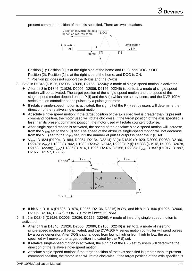
3 Devices
present command position of the axis specified. There are two situations.
LSN
DOG
LSP[2] [1 ]
Limit swi tch
Direction in which the axis specif ied returns home
Home
Limit s wi tc h
Position (1): Position [1] is at the right side of the home and DOG, and DOG is OFF. Position (2): Position [2] is at the right side of the home, and DOG is ON. *: Position (2) does not support the B-axis and the C-axis.
8. Bit 8 in D1846 (D1926, D2006, D2086, D2166, D2246): A mode of single-speed motion is activated. After bit 8 in D1846 (D1926, D2006, D2086, D2166, D2246) is set to 1, a mode of single-speed
motion will be activated. The target position of the single-speed motion and the speed of the single-speed motion depend on the P (I) and the V (I) which are set by users, and the DVP-10PM series motion controller sends pulses by a pulse generator.
If relative single-speed motion is activated, the sign bit of the P (I) set by users will determine the direction of the relative single-speed motion.
Absolute single-speed motion: If the target position of the axis specified is greater than its present command position, the motor used will rotate clockwise. If the target position of the axis specified is less than its present command position, the motor used will rotate counterclockwise.
After single-speed motion is activated, the speed of the absolute single-speed motion will increase from the VBIAS set to the V (I) set. The speed of the absolute single-speed motion will not decrease from the V (I) set to the VBIAS set until the number of pulses output is near the P (I) set.
VBIAS: D1824 (D1904, D1984, D2054, D2134, D2214); V (I): D1840 (D1920, D2000, D2080, D2160, D2240); VMAX: D1822 (D1902, D1982, D2062, D2142, D2222); P (I): D1838 (D1918, D1998, D2078, D2158, D2238); TACC: D1836 (D1916, D1996, D2076, D2156, D2236); TDEC: D1837 (D1917, D1997, D2077, D2157, D2237)
Speed TACC TDEC
VMAX
Time
VBIAS
Start
V(I) P(I)
If bit 6 in D1816 (D1896, D1976, D2056, D2136, D2216) is ON, and bit 8 in D1846 (D1926, D2006,
D2086, D2166, D2246) is ON, Y0~Y3 will execute PWM. 9. Bit 9 in D1846 (D1926, D2006, D2086, D2166, D2246): A mode of inserting single-speed motion is
activated. After bit 9 in D1846 (D1926, D2006, D2086, D2166, D2246) is set to 1, a mode of inserting
single-speed motion will be activated, and the DVP-10PM series motion controller will send pulses by a pulse generator. After DOG’s signal goes from low to high or from high to low, the axis specified will move to the target position indicated by the P (I) set.
If relative single-speed motion is activated, the sign bit of the P (I) set by users will determine the direction of the relative single-speed motion.
Absolute single-speed motion: If the target position of the axis specified is greater than its present command position, the motor used will rotate clockwise. If the target position of the axis specified is
DVP-10PM Application Manual 3-61
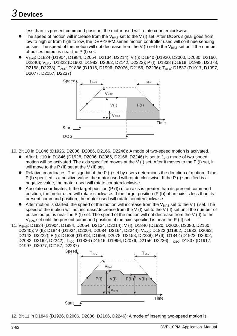
3 Devices
less than its present command position, the motor used will rotate counterclockwise. The speed of motion will increase from the VBIAS set to the V (I) set. After DOG’s signal goes from
low to high or from high to low, the DVP-10PM series motion controller used will continue sending pulses. The speed of the motion will not decrease from the V (I) set to the VBIAS set until the number of pulses output is near the P (I) set.
VBIAS: D1824 (D1904, D1984, D2054, D2134, D2214); V (I): D1840 (D1920, D2000, D2080, D2160, D2240); VMAX: D1822 (D1902, D1982, D2062, D2142, D2222); P (I): D1838 (D1918, D1998, D2078, D2158, D2238); TACC: D1836 (D1916, D1996, D2076, D2156, D2236); TDEC: D1837 (D1917, D1997, D2077, D2157, D2237)
Speed TACC TDEC
VMAX
Time
VBIAS
Start
V(I) P(I)
DOG
10. Bit 10 in D1846 (D1926, D2006, D2086, D2166, D2246): A mode of two-speed motion is activated. After bit 10 in D1846 (D1926, D2006, D2086, D2166, D2246) is set to 1, a mode of two-speed
motion will be activated. The axis specified moves at the V (I) set. After it moves to the P (I) set, it will move to the P (II) set at the V (II) set.
Relative coordinates: The sign bit of the P (I) set by users determines the direction of motion. If the P (I) specified is a positive value, the motor used will rotate clockwise. If the P (I) specified is a negative value, the motor used will rotate counterclockwise.
Absolute coordinates: If the target position (P (I)) of an axis is greater than its present command position, the motor used will rotate clockwise. If the target position (P (I)) of an axis is less than its present command position, the motor used will rotate counterclockwise.
After motion is started, the speed of the motion will increase from the VBIAS set to the V (I) set. The speed of the motion will not increase/decrease from the V (I) set to the V (II) set until the number of pulses output is near the P (I) set. The speed of the motion will not decrease from the V (II) to the VBIAS set until the present command position of the axis specified is near the P (II) set.
11. VBIAS: D1824 (D1904, D1984, D2054, D2134, D2214); V (I): D1840 (D1920, D2000, D2080, D2160, D2240); V (II): D1844 (D1924, D2004, D2084, D2164, D2244); VMAX: D1822 (D1902, D1982, D2062, D2142, D2222); P (I): D1838 (D1918, D1998, D2078, D2158, D2238); P (II): D1842 (D1922, D2002, D2082, D2162, D2242); TACC: D1836 (D1916, D1996, D2076, D2156, D2236); TDEC: D1837 (D1917, D1997, D2077, D2157, D2237)
Speed TACC TDEC
VMAX
Time
VBIAS
Start
V(I) V(II)P(II)P(I)
12. Bit 11 in D1846 (D1926, D2006, D2086, D2166, D2246): A mode of inserting two-speed motion is
DVP-10PM Application Manual 3-62
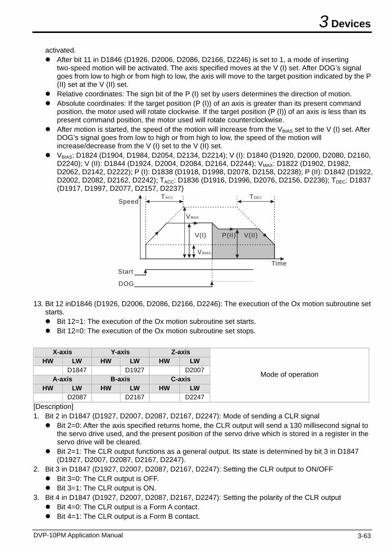
3 Devices
activated. After bit 11 in D1846 (D1926, D2006, D2086, D2166, D2246) is set to 1, a mode of inserting
two-speed motion will be activated. The axis specified moves at the V (I) set. After DOG’s signal goes from low to high or from high to low, the axis will move to the target position indicated by the P (II) set at the V (II) set.
Relative coordinates: The sign bit of the P (I) set by users determines the direction of motion. Absolute coordinates: If the target position (P (I)) of an axis is greater than its present command
position, the motor used will rotate clockwise. If the target position (P (I)) of an axis is less than its present command position, the motor used will rotate counterclockwise.
After motion is started, the speed of the motion will increase from the VBIAS set to the V (I) set. After DOG’s signal goes from low to high or from high to low, the speed of the motion will increase/decrease from the V (I) set to the V (II) set.
VBIAS: D1824 (D1904, D1984, D2054, D2134, D2214); V (I): D1840 (D1920, D2000, D2080, D2160, D2240); V (II): D1844 (D1924, D2004, D2084, D2164, D2244); VMAX: D1822 (D1902, D1982, D2062, D2142, D2222); P (I): D1838 (D1918, D1998, D2078, D2158, D2238); P (II): D1842 (D1922, D2002, D2082, D2162, D2242); TACC: D1836 (D1916, D1996, D2076, D2156, D2236); TDEC: D1837 (D1917, D1997, D2077, D2157, D2237)
SpeedTACC TDEC
VMAX
Time
VBIAS
Start
V(I) V(II)P(II)
DOG
13. Bit 12 inD1846 (D1926, D2006, D2086, D2166, D2246): The execution of the Ox motion subroutine set starts. Bit 12=1: The execution of the Ox motion subroutine set starts. Bit 12=0: The execution of the Ox motion subroutine set stops.
X-axis Y-axis Z-axis
HW LW HW LW HW LW D1847 D1927 D2007
A-axis B-axis C-axis HW LW HW LW HW LW
D2087 D2167 D2247
Mode of operation
[Description] 1. Bit 2 in D1847 (D1927, D2007, D2087, D2167, D2247): Mode of sending a CLR signal Bit 2=0: After the axis specified returns home, the CLR output will send a 130 millisecond signal to
the servo drive used, and the present position of the servo drive which is stored in a register in the servo drive will be cleared.
Bit 2=1: The CLR output functions as a general output. Its state is determined by bit 3 in D1847 (D1927, D2007, D2087, D2167, D2247).
2. Bit 3 in D1847 (D1927, D2007, D2087, D2167, D2247): Setting the CLR output to ON/OFF Bit 3=0: The CLR output is OFF. Bit 3=1: The CLR output is ON.
3. Bit 4 in D1847 (D1927, D2007, D2087, D2167, D2247): Setting the polarity of the CLR output Bit 4=0: The CLR output is a Form A contact. Bit 4=1: The CLR output is a Form B contact.
DVP-10PM Application Manual 3-63
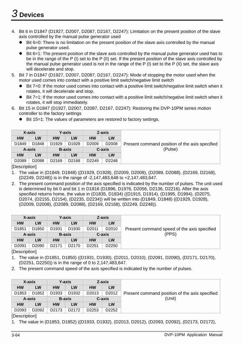
3 Devices
4. Bit 6 in D1847 (D1927, D2007, D2087, D2167, D2247): Limitation on the present position of the slave axis controlled by the manual pulse generator used Bit 6=0: There is no limitation on the present position of the slave axis controlled by the manual
pulse generator used. Bit 6=1: The present position of the slave axis controlled by the manual pulse generator used has to
be in the range of the P (I) set to the P (II) set. If the present position of the slave axis controlled by the manual pulse generator used is not in the range of the P (I) set to the P (II) set, the slave axis will decelerate and stop.
5. Bit 7 in D1847 (D1927, D2007, D2087, D2167, D2247): Mode of stopping the motor used when the motor used comes into contact with a positive limit switch/negative limit switch Bit 7=0: If the motor used comes into contact with a positive limit switch/negative limit switch when it
rotates, it will decelerate and stop. Bit 7=1: If the motor used comes into contact with a positive limit switch/negative limit switch when it
rotates, it will stop immediately. 6. Bit 15 in D1847 (D1927, D2007, D2087, D2167, D2247): Restoring the DVP-10PM series motion
controller to the factory settings Bit 15=1: The values of parameters are restored to factory settings.
X-axis Y-axis Z-axis
HW LW HW LW HW LW D1849 D1848 D1929 D1928 D2009 D2008
A-axis B-axis C-axis HW LW HW LW HW LW
D2089 D2088 D2169 D2168 D2249 D2248
Present command position of the axis specified (Pulse)
[Description] 1. The value in (D1849, D1848) ((D1929, D1928), (D2009, D2008), (D2089, D2088), (D2169, D2168),
(D2249, D2248)) is in the range of -2,147,483,648 to +2,147,483,647. 2. The present command position of the axis specified is indicated by the number of pulses. The unit used
is determined by bit 0 and bit 1 in D1816 (D1896, D1976, D2056, D2136, D2216). After the axis specified returns home, the value in (D1835, D1834) ((D1915, D1914), (D1995, D1994), (D2075, D2074, (D2155, D2154), (D2235, D2234)) will be written into (D1849, D1848) ((D1929, D1928), (D2009, D2008), (D2089, D2088), (D2169, D2168), (D2249, D2248)).
X-axis Y-axis Z-axis
HW LW HW LW HW LW D1851 D1850 D1931 D1930 D2011 D2010
A-axis B-axis C-axis HW LW HW LW HW LW
D2091 D2090 D2171 D2170 D2251 D2250
Present command speed of the axis specified (PPS)
[Description] 1. The value in (D1851, D1850) ((D1931, D1930), (D2011, D2010), (D2091, D2090), (D2171, D2170),
(D2251, D2250)) is in the range of 0 to 2,147,483,647. 2. The present command speed of the axis specified is indicated by the number of pulses.
X-axis Y-axis Z-axis
HW LW HW LW HW LW D1853 D1852 D1933 D1932 D2013 D2012
A-axis B-axis C-axis HW LW HW LW HW LW
D2093 D2092 D2173 D2172 D2253 D2252
Present command position of the axis specified (Unit)
[Description] 1. The value in (D1853, D1852) ((D1933, D1932), (D2013, D2012), (D2093, D2092), (D2173, D2172),
DVP-10PM Application Manual 3-64
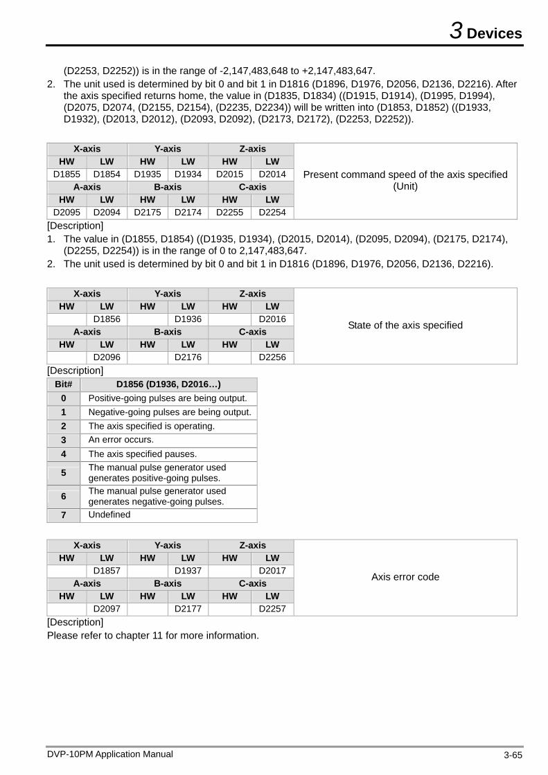
3 Devices
DVP-10PM Application Manual 3-65
(D2253, D2252)) is in the range of -2,147,483,648 to +2,147,483,647. 2. The unit used is determined by bit 0 and bit 1 in D1816 (D1896, D1976, D2056, D2136, D2216). After
the axis specified returns home, the value in (D1835, D1834) ((D1915, D1914), (D1995, D1994), (D2075, D2074, (D2155, D2154), (D2235, D2234)) will be written into (D1853, D1852) ((D1933, D1932), (D2013, D2012), (D2093, D2092), (D2173, D2172), (D2253, D2252)).
X-axis Y-axis Z-axis
HW LW HW LW HW LW D1855 D1854 D1935 D1934 D2015 D2014
A-axis B-axis C-axis HW LW HW LW HW LW
D2095 D2094 D2175 D2174 D2255 D2254
Present command speed of the axis specified (Unit)
[Description] 1. The value in (D1855, D1854) ((D1935, D1934), (D2015, D2014), (D2095, D2094), (D2175, D2174),
(D2255, D2254)) is in the range of 0 to 2,147,483,647. 2. The unit used is determined by bit 0 and bit 1 in D1816 (D1896, D1976, D2056, D2136, D2216).
X-axis Y-axis Z-axis HW LW HW LW HW LW
D1856 D1936 D2016A-axis B-axis C-axis
HW LW HW LW HW LW D2096 D2176 D2256
State of the axis specified
[Description] Bit# D1856 (D1936, D2016…)
0 Positive-going pulses are being output. 1 Negative-going pulses are being output.2 The axis specified is operating. 3 An error occurs. 4 The axis specified pauses.
5 The manual pulse generator used generates positive-going pulses.
6 The manual pulse generator used generates negative-going pulses.
7 Undefined
X-axis Y-axis Z-axis
HW LW HW LW HW LW D1857 D1937 D2017
A-axis B-axis C-axis HW LW HW LW HW LW
D2097 D2177 D2257
Axis error code
[Description] Please refer to chapter 11 for more information.
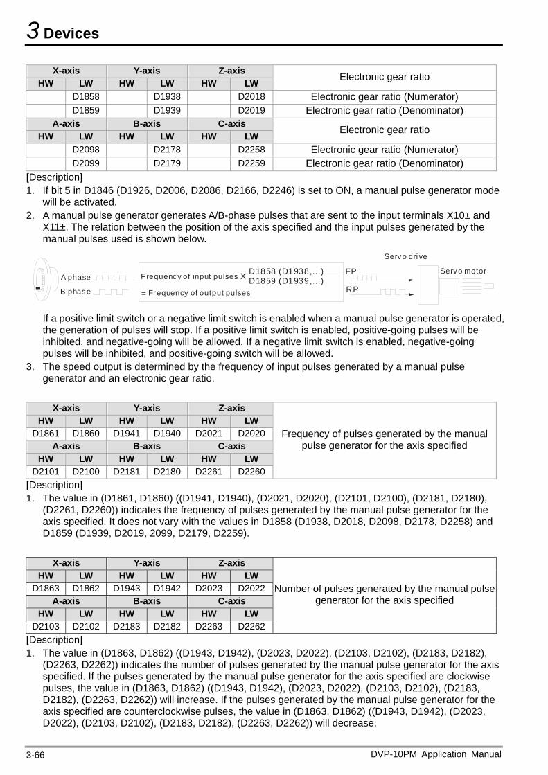
3 Devices
X-axis Y-axis Z-axis HW LW HW LW HW LW Electronic gear ratio
D1858 D1938 D2018 Electronic gear ratio (Numerator) D1859 D1939 D2019 Electronic gear ratio (Denominator)
A-axis B-axis C-axis HW LW HW LW HW LW Electronic gear ratio
D2098 D2178 D2258 Electronic gear ratio (Numerator) D2099 D2179 D2259 Electronic gear ratio (Denominator)
[Description] 1. If bit 5 in D1846 (D1926, D2006, D2086, D2166, D2246) is set to ON, a manual pulse generator mode
will be activated. 2. A manual pulse generator generates A/B-phase pulses that are sent to the input terminals X10± and
X11±. The relation between the position of the axis specified and the input pulses generated by the manual pulses used is shown below.
A phase
B phas e
FP
RP
Servo dri ve
Servo motorFrequenc y of input pulses X
= Frequency of output pulses
D1858 (D1938,...)D1859 (D1939,...)
If a positive limit switch or a negative limit switch is enabled when a manual pulse generator is operated, the generation of pulses will stop. If a positive limit switch is enabled, positive-going pulses will be inhibited, and negative-going will be allowed. If a negative limit switch is enabled, negative-going pulses will be inhibited, and positive-going switch will be allowed.
3. The speed output is determined by the frequency of input pulses generated by a manual pulse generator and an electronic gear ratio.
X-axis Y-axis Z-axis
HW LW HW LW HW LW D1861 D1860 D1941 D1940 D2021 D2020
A-axis B-axis C-axis HW LW HW LW HW LW
D2101 D2100 D2181 D2180 D2261 D2260
Frequency of pulses generated by the manual pulse generator for the axis specified
[Description] 1. The value in (D1861, D1860) ((D1941, D1940), (D2021, D2020), (D2101, D2100), (D2181, D2180),
(D2261, D2260)) indicates the frequency of pulses generated by the manual pulse generator for the axis specified. It does not vary with the values in D1858 (D1938, D2018, D2098, D2178, D2258) and D1859 (D1939, D2019, 2099, D2179, D2259).
X-axis Y-axis Z-axis
HW LW HW LW HW LW D1863 D1862 D1943 D1942 D2023 D2022
A-axis B-axis C-axis HW LW HW LW HW LW
D2103 D2102 D2183 D2182 D2263 D2262
Number of pulses generated by the manual pulse generator for the axis specified
[Description] 1. The value in (D1863, D1862) ((D1943, D1942), (D2023, D2022), (D2103, D2102), (D2183, D2182),
(D2263, D2262)) indicates the number of pulses generated by the manual pulse generator for the axis specified. If the pulses generated by the manual pulse generator for the axis specified are clockwise pulses, the value in (D1863, D1862) ((D1943, D1942), (D2023, D2022), (D2103, D2102), (D2183, D2182), (D2263, D2262)) will increase. If the pulses generated by the manual pulse generator for the axis specified are counterclockwise pulses, the value in (D1863, D1862) ((D1943, D1942), (D2023, D2022), (D2103, D2102), (D2183, D2182), (D2263, D2262)) will decrease.
DVP-10PM Application Manual 3-66
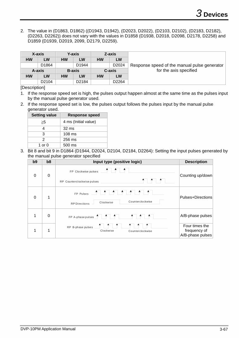
3 Devices
DVP-10PM Application Manual 3-67
2. The value in (D1863, D1862) ((D1943, D1942), (D2023, D2022), (D2103, D2102), (D2183, D2182), (D2263, D2262)) does not vary with the values in D1858 (D1938, D2018, D2098, D2178, D2258) and D1859 (D1939, D2019, 2099, D2179, D2259).
X-axis Y-axis Z-axis
HW LW HW LW HW LW D1864 D1944 D2024
A-axis B-axis C-axis HW LW HW LW HW LW
D2104 D2184 D2264
Response speed of the manual pulse generator for the axis specified
[Description] 1. If the response speed set is high, the pulses output happen almost at the same time as the pulses input
by the manual pulse generator used. 2. If the response speed set is low, the pulses output follows the pulses input by the manual pulse
generator used. Setting value Response speed
≧5 4 ms (Initial value)
4 32 ms 3 108 ms 2 256 ms
1 or 0 500 ms 3. Bit 8 and bit 9 in D1864 (D1944, D2024, D2104, D2184, D2264): Setting the input pulses generated by
the manual pulse generator specified b9 b8 Input type (positive logic) Description
0 0 FP Clockwise pulses
RP Counterclockwise pulses
Counting up/down
0 1 FP Pulses
RP Directions Counterclockwise Clockwise
Pulses+Directions
1 0 A/B-phase pulses
1 1 Counterclockwise Clockwise
FP A-phase pulses
RP B-phase pulses
Four times the frequency of
A/B-phase pulses
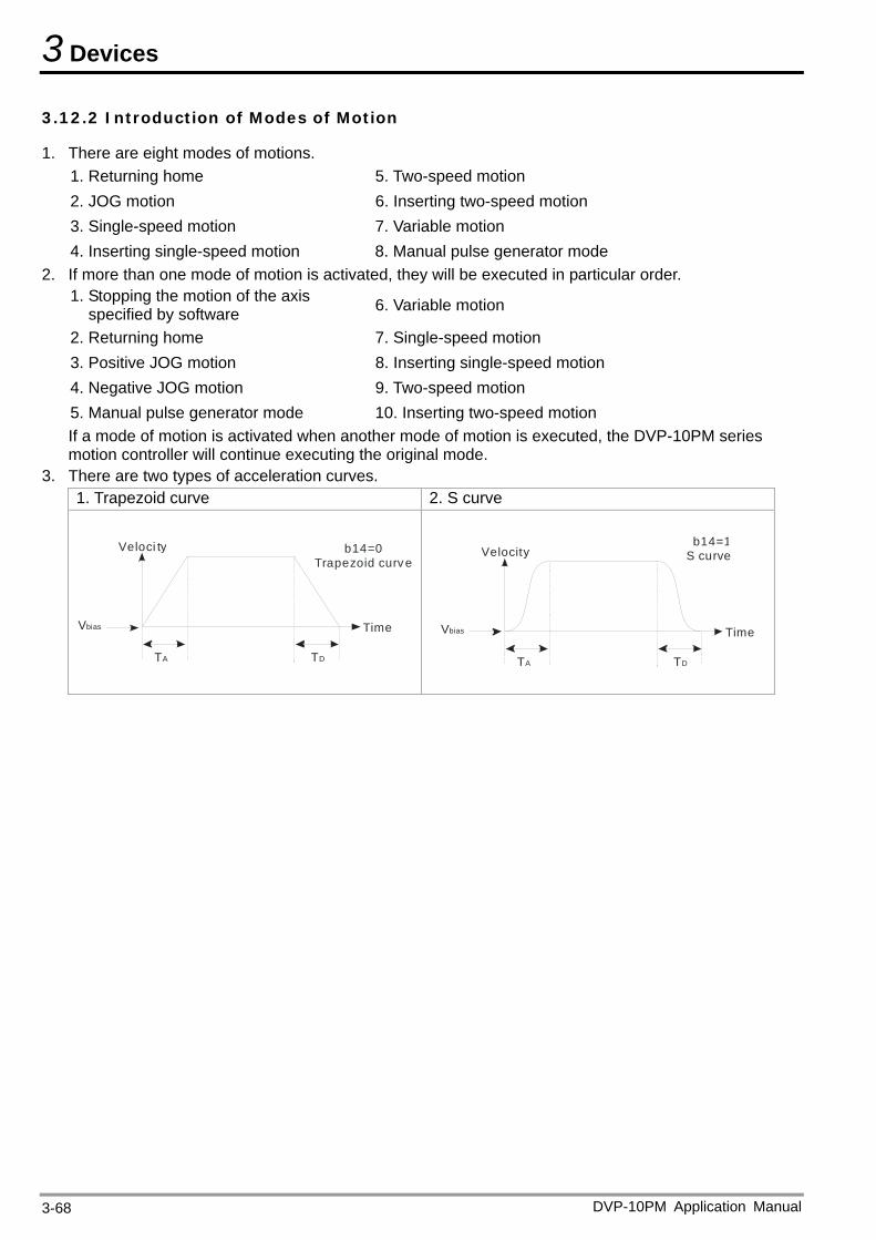
3 Devices
DVP-10PM Application Manual 3-68
3.12.2 Introduction of Modes of Motion
1. There are eight modes of motions. 1. Returning home 5. Two-speed motion 2. JOG motion 6. Inserting two-speed motion 3. Single-speed motion 7. Variable motion 4. Inserting single-speed motion 8. Manual pulse generator mode
2. If more than one mode of motion is activated, they will be executed in particular order. 1. Stopping the motion of the axis
specified by software 6. Variable motion
2. Returning home 7. Single-speed motion 3. Positive JOG motion 8. Inserting single-speed motion 4. Negative JOG motion 9. Two-speed motion 5. Manual pulse generator mode 10. Inserting two-speed motion If a mode of motion is activated when another mode of motion is executed, the DVP-10PM series motion controller will continue executing the original mode.
3. There are two types of acceleration curves. 1. Trapezoid curve 2. S curve
T
Veloci ty
A TD
Vbias Time
b14=0 Trapezoid curv e
T
Velocity
A DT
Vbias Time
b14=1S curve
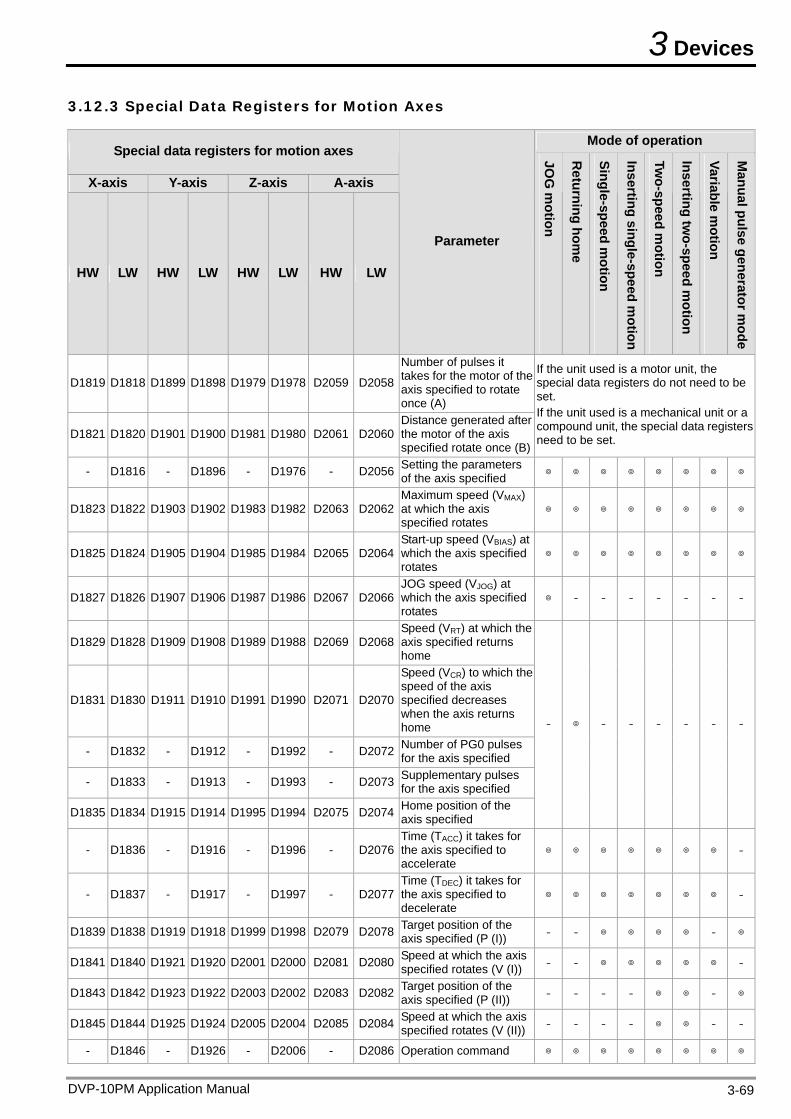
3 Devices
3.12.3 Special Data Registers for Motion Axes
Mode of operation Special data registers for motion axes
X-axis Y-axis Z-axis A-axis
HW LW HW LW HW LW HW LW
Parameter JO
G m
otion
Returning hom
e
Single-speed motion
Inserting single-speed motion
Two-speed m
otion
Inserting two-speed m
otion
Variable motion
Manual pulse generator m
ode
D1819 D1818 D1899 D1898 D1979 D1978 D2059 D2058
Number of pulses it takes for the motor of the axis specified to rotate once (A)
D1821 D1820 D1901 D1900 D1981 D1980 D2061 D2060Distance generated after the motor of the axis specified rotate once (B)
If the unit used is a motor unit, the special data registers do not need to be set. If the unit used is a mechanical unit or a compound unit, the special data registers need to be set.
- D1816 - D1896 - D1976 - D2056 Setting the parameters of the axis specified
D1823 D1822 D1903 D1902 D1983 D1982 D2063 D2062Maximum speed (VMAX) at which the axis specified rotates
D1825 D1824 D1905 D1904 D1985 D1984 D2065 D2064Start-up speed (VBIAS) at which the axis specified rotates
D1827 D1826 D1907 D1906 D1987 D1986 D2067 D2066JOG speed (VJOG) at which the axis specified rotates
- - - - - - -
D1829 D1828 D1909 D1908 D1989 D1988 D2069 D2068Speed (VRT) at which the axis specified returns home
D1831 D1830 D1911 D1910 D1991 D1990 D2071 D2070
Speed (VCR) to which the speed of the axis specified decreases when the axis returns home
- D1832 - D1912 - D1992 - D2072 Number of PG0 pulses for the axis specified
- D1833 - D1913 - D1993 - D2073 Supplementary pulses for the axis specified
D1835 D1834 D1915 D1914 D1995 D1994 D2075 D2074 Home position of the axis specified
- - - - - - -
- D1836 - D1916 - D1996 - D2076Time (TACC) it takes for the axis specified to accelerate
-
- D1837 - D1917 - D1997 - D2077Time (TDEC) it takes for the axis specified to decelerate
-
D1839 D1838 D1919 D1918 D1999 D1998 D2079 D2078 Target position of the axis specified (P (I)) - - -
D1841 D1840 D1921 D1920 D2001 D2000 D2081 D2080 Speed at which the axis specified rotates (V (I)) - - -
D1843 D1842 D1923 D1922 D2003 D2002 D2083 D2082 Target position of the axis specified (P (II)) - - - - -
D1845 D1844 D1925 D1924 D2005 D2004 D2085 D2084 Speed at which the axis specified rotates (V (II)) - - - - - -
- D1846 - D1926 - D2006 - D2086 Operation command
DVP-10PM Application Manual 3-69
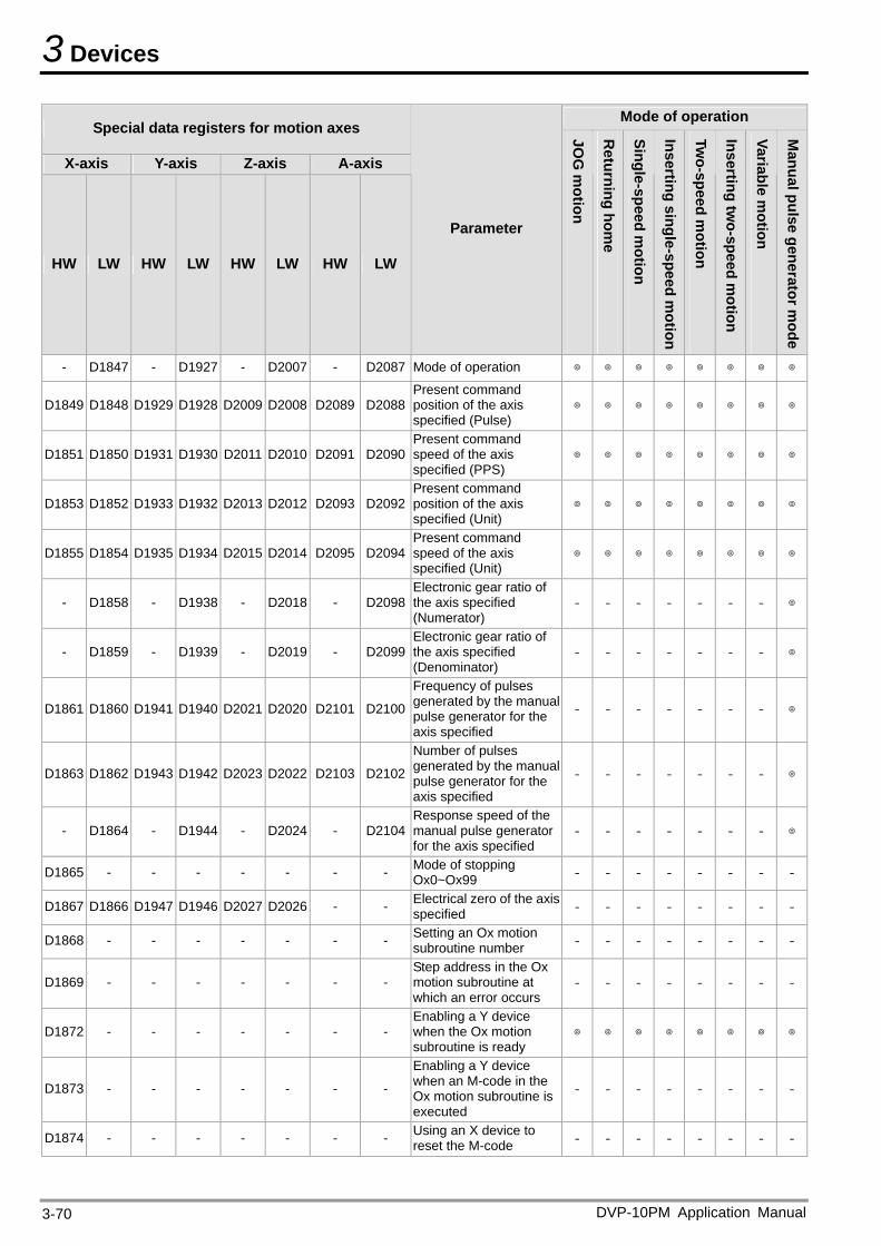
3 Devices
DVP-10PM Application Manual 3-70
Mode of operation Special data registers for motion axes
X-axis Y-axis Z-axis A-axis
HW LW HW LW HW LW HW LW
Parameter
JOG
motion
Returning hom
e
Single-speed motion
Inserting single-speed motion
Two-speed m
otion
Inserting two-speed m
otion
Variable motion
Manual pulse generator m
ode
- D1847 - D1927 - D2007 - D2087 Mode of operation
D1849 D1848 D1929 D1928 D2009 D2008 D2089 D2088Present command position of the axis specified (Pulse)
D1851 D1850 D1931 D1930 D2011 D2010 D2091 D2090Present command speed of the axis specified (PPS)
D1853 D1852 D1933 D1932 D2013 D2012 D2093 D2092Present command position of the axis specified (Unit)
D1855 D1854 D1935 D1934 D2015 D2014 D2095 D2094Present command speed of the axis specified (Unit)
- D1858 - D1938 - D2018 - D2098Electronic gear ratio of the axis specified (Numerator)
- - - - - - -
- D1859 - D1939 - D2019 - D2099Electronic gear ratio of the axis specified (Denominator)
- - - - - - -
D1861 D1860 D1941 D1940 D2021 D2020 D2101 D2100
Frequency of pulses generated by the manual pulse generator for the axis specified
- - - - - - -
D1863 D1862 D1943 D1942 D2023 D2022 D2103 D2102
Number of pulses generated by the manual pulse generator for the axis specified
- - - - - - -
- D1864 - D1944 - D2024 - D2104Response speed of the manual pulse generator for the axis specified
- - - - - - -
D1865 - - - - - - - Mode of stopping Ox0~Ox99 - - - - - - - -
D1867 D1866 D1947 D1946 D2027 D2026 - - Electrical zero of the axisspecified - - - - - - - -
D1868 - - - - - - - Setting an Ox motion subroutine number - - - - - - - -
D1869 - - - - - - - Step address in the Ox motion subroutine at which an error occurs
- - - - - - - -
D1872 - - - - - - - Enabling a Y device when the Ox motion subroutine is ready
D1873 - - - - - - -
Enabling a Y device when an M-code in the Ox motion subroutine is executed
- - - - - - - -
D1874 - - - - - - - Using an X device to reset the M-code - - - - - - - -
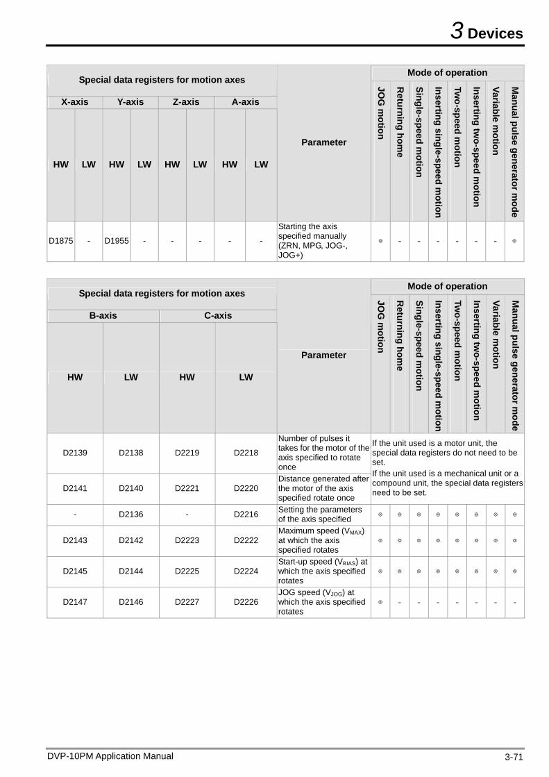
3 Devices
DVP-10PM Application Manual 3-71
Mode of operation Special data registers for motion axes
X-axis Y-axis Z-axis A-axis
HW LW HW LW HW LW HW LW
Parameter
JOG
motion
Returning hom
e
Single-speed motion
Inserting single-speed motion
Two-speed m
otion
Inserting two-speed m
otion
Variable motion
Manual pulse generator m
ode
D1875 - D1955 - - - - -
Starting the axis specified manually (ZRN, MPG, JOG-, JOG+)
- - - - - -
Mode of operation
Special data registers for motion axes
B-axis C-axis
HW LW HW LW
Parameter
JOG
motion
Returning hom
e
Single-speed motion
Inserting single-speed motion
Two-speed m
otion
Inserting two-speed m
otion
Variable motion
Manual pulse generator m
ode
D2139 D2138 D2219 D2218
Number of pulses it takes for the motor of the axis specified to rotate once
D2141 D2140 D2221 D2220 Distance generated after the motor of the axis specified rotate once
If the unit used is a motor unit, the special data registers do not need to be set. If the unit used is a mechanical unit or a compound unit, the special data registers need to be set.
- D2136 - D2216 Setting the parameters of the axis specified
D2143 D2142 D2223 D2222 Maximum speed (VMAX) at which the axis specified rotates
D2145 D2144 D2225 D2224 Start-up speed (VBIAS) at which the axis specified rotates
D2147 D2146 D2227 D2226 JOG speed (VJOG) at which the axis specified rotates
- - - - - - -
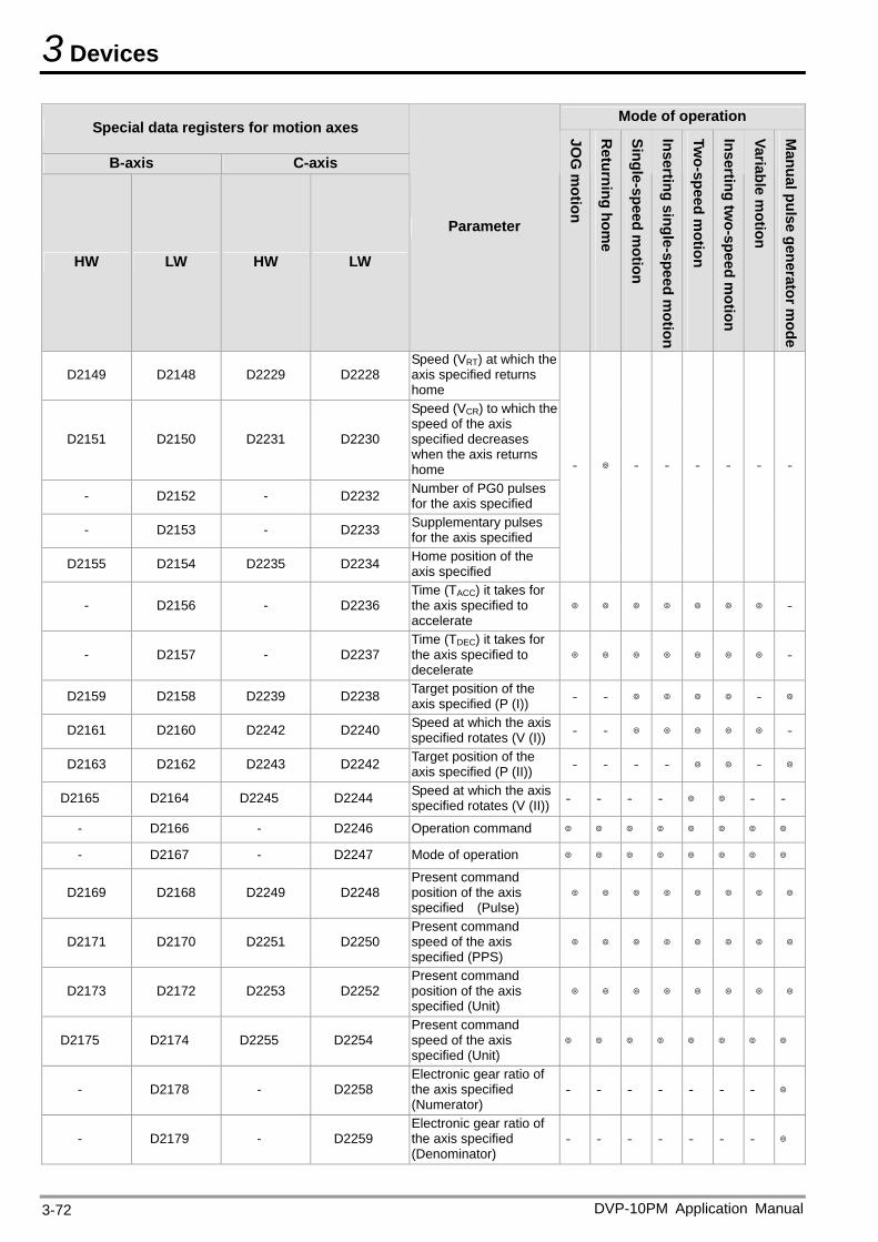
3 Devices
Mode of operation Special data registers for motion axes
B-axis C-axis
HW LW HW LW
Parameter
JOG
motion
Returning hom
e
Single-speed motion
Inserting single-speed motion
Two-speed m
otion
Inserting two-speed m
otion
Variable motion
Manual pulse generator m
ode
D2149 D2148 D2229 D2228 Speed (VRT) at which the axis specified returns home
D2151 D2150 D2231 D2230
Speed (VCR) to which the speed of the axis specified decreases when the axis returns home
- D2152 - D2232 Number of PG0 pulses for the axis specified
- D2153 - D2233 Supplementary pulses for the axis specified
D2155 D2154 D2235 D2234 Home position of the axis specified
- - - - - - -
- D2156 - D2236 Time (TACC) it takes for the axis specified to accelerate
-
- D2157 - D2237 Time (TDEC) it takes for the axis specified to decelerate
-
D2159 D2158 D2239 D2238 Target position of the axis specified (P (I)) - - -
D2161 D2160 D2242 D2240 Speed at which the axis specified rotates (V (I)) - - -
D2163 D2162 D2243 D2242 Target position of the axis specified (P (II)) - - - - -
D2165 D2164 D2245 D2244 Speed at which the axis specified rotates (V (II)) - - - - - -
- D2166 - D2246 Operation command
- D2167 - D2247 Mode of operation
D2169 D2168 D2249 D2248 Present command position of the axis specified (Pulse)
D2171 D2170 D2251 D2250 Present command speed of the axis specified (PPS)
D2173 D2172 D2253 D2252 Present command position of the axis specified (Unit)
D2175 D2174 D2255 D2254 Present command speed of the axis specified (Unit)
- D2178 - D2258 Electronic gear ratio of the axis specified (Numerator)
- - - - - - -
- D2179 - D2259 Electronic gear ratio of the axis specified (Denominator)
- - - - - - -
DVP-10PM Application Manual 3-72
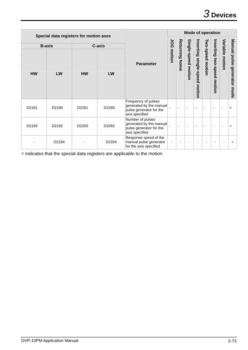
3 Devices
DVP-10PM Application Manual 3-73
Mode of operation Special data registers for motion axes
B-axis C-axis
HW LW HW LW
Parameter
JOG
motion
Returning hom
e
Single-speed motion
Inserting single-speed motion
Two-speed m
otion
Inserting two-speed m
otion
Variable motion
Manual pulse generator m
ode
D2181 D2180 D2261 D2260
Frequency of pulses generated by the manual pulse generator for the axis specified
- - - - - - -
D2183 D2182 D2263 D2262
Number of pulses generated by the manual pulse generator for the axis specified
- - - - - - -
- D2184 - D2264 Response speed of the manual pulse generator for the axis specified
- - - - - - -
indicates that the special data registers are applicable to the motion.

3 Devices
DVP-10PM Application Manual 3-74
MEMO
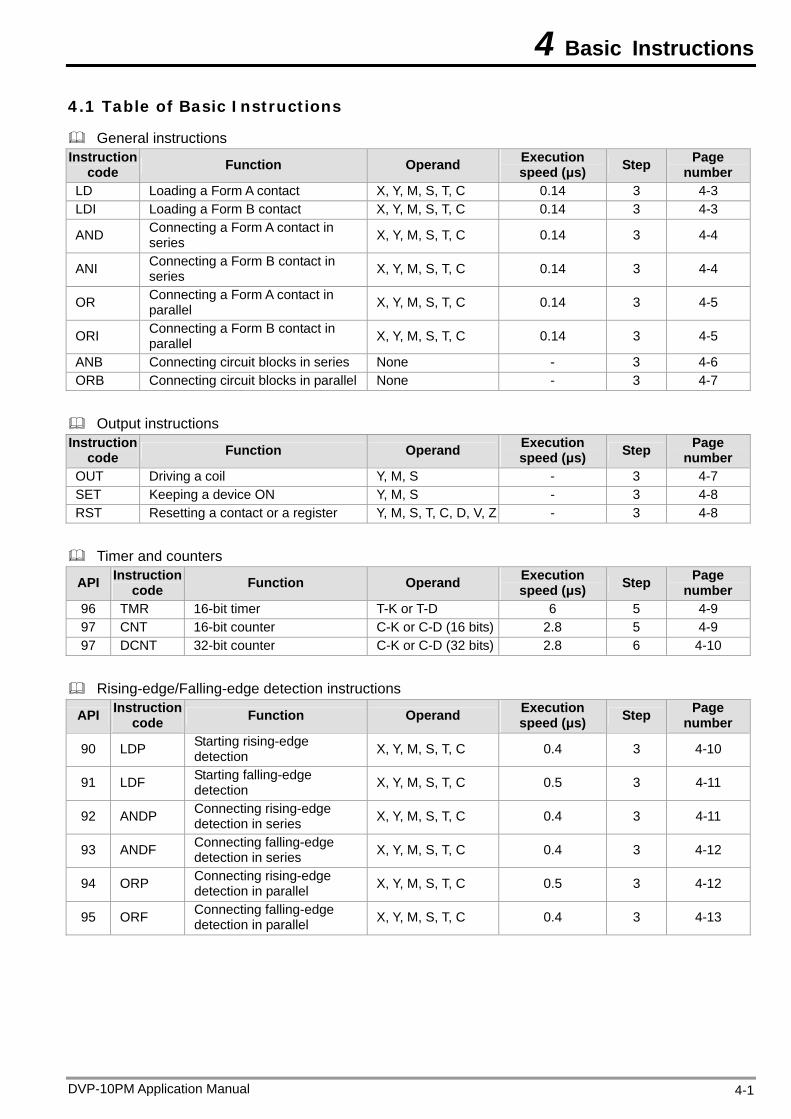
4 Basic Instructions
4.1 Table of Basic Instructions
General instructions Instruction
code Function Operand Execution speed (μs) Step Page
number LD Loading a Form A contact X, Y, M, S, T, C 0.14 3 4-3 LDI Loading a Form B contact X, Y, M, S, T, C 0.14 3 4-3
AND Connecting a Form A contact in series X, Y, M, S, T, C 0.14 3 4-4
ANI Connecting a Form B contact in series X, Y, M, S, T, C 0.14 3 4-4
OR Connecting a Form A contact in parallel X, Y, M, S, T, C 0.14 3 4-5
ORI Connecting a Form B contact in parallel X, Y, M, S, T, C 0.14 3 4-5
ANB Connecting circuit blocks in series None - 3 4-6 ORB Connecting circuit blocks in parallel None - 3 4-7
Output instructions Instruction
code Function Operand Execution speed (μs) Step Page
number OUT Driving a coil Y, M, S - 3 4-7 SET Keeping a device ON Y, M, S - 3 4-8 RST Resetting a contact or a register Y, M, S, T, C, D, V, Z - 3 4-8
Timer and counters
API Instruction code Function Operand Execution
speed (μs) Step Page number
96 TMR 16-bit timer T-K or T-D 6 5 4-9 97 CNT 16-bit counter C-K or C-D (16 bits) 2.8 5 4-9 97 DCNT 32-bit counter C-K or C-D (32 bits) 2.8 6 4-10
Rising-edge/Falling-edge detection instructions
API Instruction code Function Operand Execution
speed (μs) Step Page number
90 LDP Starting rising-edge detection X, Y, M, S, T, C 0.4 3 4-10
91 LDF Starting falling-edge detection X, Y, M, S, T, C 0.5 3 4-11
92 ANDP Connecting rising-edge detection in series X, Y, M, S, T, C 0.4 3 4-11
93 ANDF Connecting falling-edge detection in series X, Y, M, S, T, C 0.4 3 4-12
94 ORP Connecting rising-edge detection in parallel X, Y, M, S, T, C 0.5 3 4-12
95 ORF Connecting falling-edge detection in parallel X, Y, M, S, T, C 0.4 3 4-13
DVP-10PM Application Manual 4-1
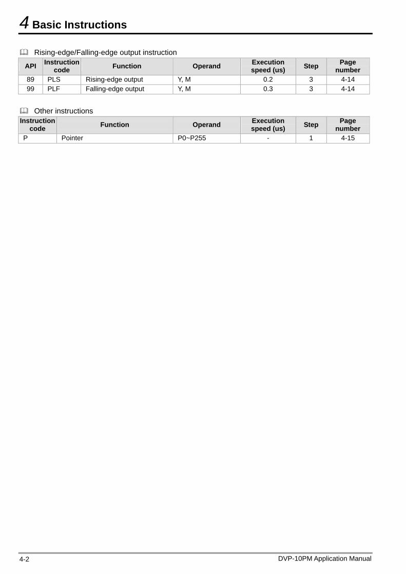
4 Basic Instructions
Rising-edge/Falling-edge output instruction
API Instruction code Function Operand Execution
speed (us) Step Page number
89 PLS Rising-edge output Y, M 0.2 3 4-14 99 PLF Falling-edge output Y, M 0.3 3 4-14
Other instructions Instruction
code Function Operand Execution speed (us) Step Page
number P Pointer P0~P255 - 1 4-15
DVP-10PM Application Manual 4-2
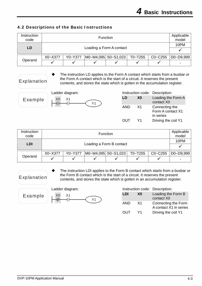
4 Basic Instructions
4.2 Descriptions of the Basic Instructions
Instruction code Function Applicable
model 10PM
LD Loading a Form A contact
X0~X377 Y0~Y377 M0~M4,095 S0~S1,023 T0~T255 C0~C255 D0~D9,999
Operand -
Exp lanat ion
The instruction LD applies to the Form A contact which starts from a busbar or the Form A contact which is the start of a circuit. It reserves the present contents, and stores the state which is gotten in the accumulation register.
Example
Ladder diagram:
X0 X1Y1
Instruction code: Description: LD X0 Loading the Form A
contact X0 AND X1 Connecting the
Form A contact X1 in series
OUT Y1 Driving the coil Y1
Instruction code Function Applicable
model 10PM
LDI Loading a Form B contact
X0~X377 Y0~Y377 M0~M4,095 S0~S1,023 T0~T255 C0~C255 D0~D9,999
Operand -
Exp lanat ion
The instruction LDI applies to the Form B contact which starts from a busbar or the Form B contact which is the start of a circuit. It reserves the present contents, and stores the state which is gotten in an accumulation register.
Example
Ladder diagram:
X0 X1Y1
Instruction code: Description: LDI X0 Loading the Form B
contact X0 AND X1 Connecting the Form
A contact X1 in seriesOUT Y1 Driving the coil Y1
DVP-10PM Application Manual 4-3
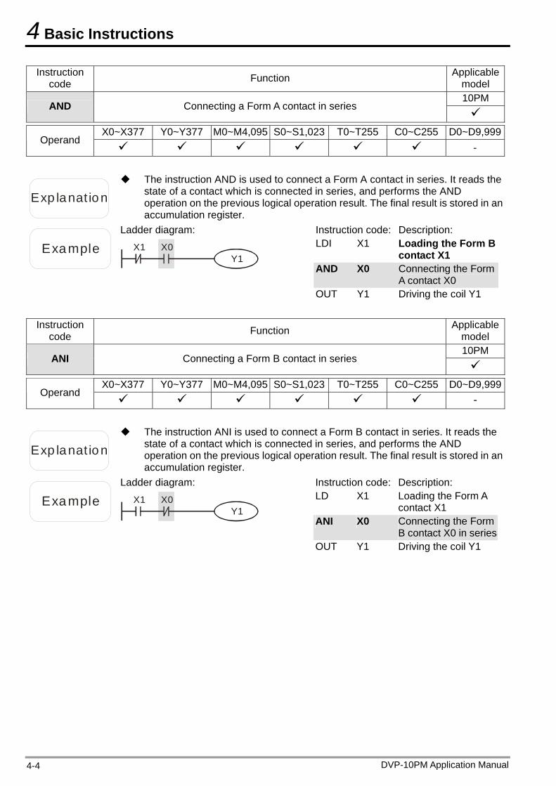
4 Basic Instructions
Instruction code Function Applicable
model 10PM
AND Connecting a Form A contact in series
X0~X377 Y0~Y377 M0~M4,095 S0~S1,023 T0~T255 C0~C255 D0~D9,999
Operand -
Exp lanat ion
The instruction AND is used to connect a Form A contact in series. It reads the state of a contact which is connected in series, and performs the AND operation on the previous logical operation result. The final result is stored in an accumulation register.
Example
Ladder diagram:
X0X1Y1
Instruction code: Description: LDI X1 Loading the Form B
contact X1 AND X0 Connecting the Form
A contact X0 OUT Y1 Driving the coil Y1
Instruction
code Function Applicable model 10PM
ANI Connecting a Form B contact in series
X0~X377 Y0~Y377 M0~M4,095 S0~S1,023 T0~T255 C0~C255 D0~D9,999
Operand -
Exp lanat ion
The instruction ANI is used to connect a Form B contact in series. It reads the state of a contact which is connected in series, and performs the AND operation on the previous logical operation result. The final result is stored in an accumulation register.
Example
Ladder diagram:
X0X1Y1
Instruction code: Description: LD X1 Loading the Form A
contact X1 ANI X0 Connecting the Form
B contact X0 in seriesOUT Y1 Driving the coil Y1
DVP-10PM Application Manual 4-4
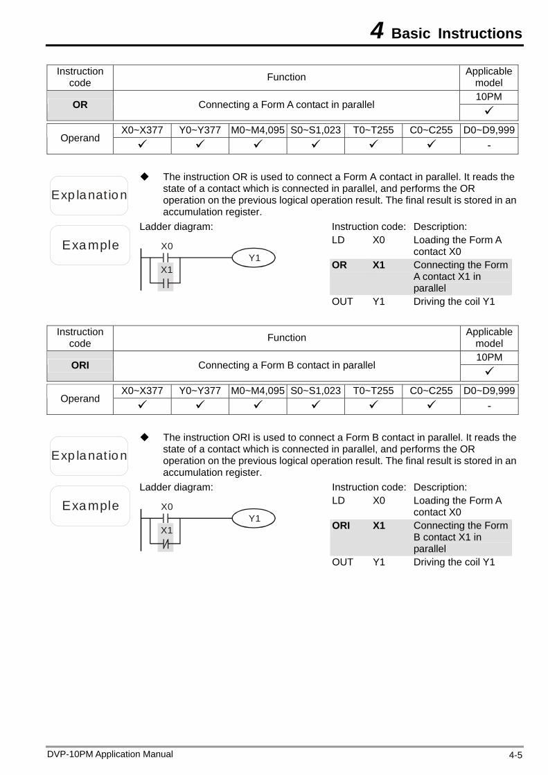
4 Basic Instructions
Instruction code Function Applicable
model 10PM
OR Connecting a Form A contact in parallel
X0~X377 Y0~Y377 M0~M4,095 S0~S1,023 T0~T255 C0~C255 D0~D9,999
Operand -
Exp lanat ion
The instruction OR is used to connect a Form A contact in parallel. It reads the state of a contact which is connected in parallel, and performs the OR operation on the previous logical operation result. The final result is stored in an accumulation register.
Example
Ladder diagram:
X0
X1Y1
Instruction code: Description: LD X0 Loading the Form A
contact X0 OR X1 Connecting the Form
A contact X1 in parallel
OUT Y1 Driving the coil Y1
Instruction code Function Applicable
model 10PM
ORI Connecting a Form B contact in parallel
X0~X377 Y0~Y377 M0~M4,095 S0~S1,023 T0~T255 C0~C255 D0~D9,999
Operand -
Exp lanat ion
The instruction ORI is used to connect a Form B contact in parallel. It reads the state of a contact which is connected in parallel, and performs the OR operation on the previous logical operation result. The final result is stored in an accumulation register.
Example
Ladder diagram:
X0
X1Y1
Instruction code: Description: LD X0 Loading the Form A
contact X0 ORI X1 Connecting the Form
B contact X1 in parallel
OUT Y1 Driving the coil Y1
DVP-10PM Application Manual 4-5
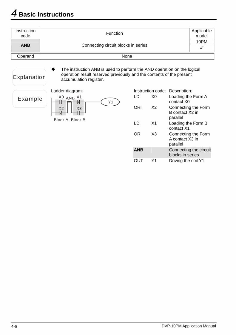
4 Basic Instructions
Instruction code Function Applicable
model 10PM
ANB Connecting circuit blocks in series
Operand None
Exp lanat ion
The instruction ANB is used to perform the AND operation on the logical operation result reserved previously and the contents of the present accumulation register.
Example
Ladder diagram: X0
X2Y1
X1
X3
ANB
Block A Block B
Instruction code: Description: LD X0 Loading the Form A
contact X0 ORI X2 Connecting the Form
B contact X2 in parallel
LDI X1 Loading the Form B contact X1
OR X3 Connecting the Form A contact X3 in parallel
ANB Connecting the circuit blocks in series
OUT Y1 Driving the coil Y1
DVP-10PM Application Manual 4-6
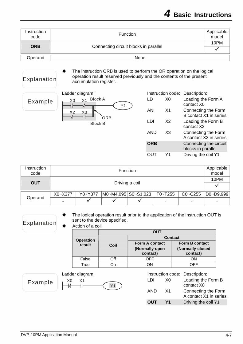
4 Basic Instructions
Instruction code Function Applicable
model 10PM
ORB Connecting circuit blocks in parallel
Operand None
Exp lanat ion
The instruction ORB is used to perform the OR operation on the logical operation result reserved previously and the contents of the present accumulation register.
Example
Ladder diagram: X0
X2Y1
X1
X3ORB
Block A
Block B
Instruction code: Description: LD X0 Loading the Form A
contact X0 ANI X1 Connecting the Form
B contact X1 in seriesLDI X2 Loading the Form B
contact X2 AND X3 Connecting the Form
A contact X3 in seriesORB Connecting the circuit
blocks in parallel OUT Y1 Driving the coil Y1
Instruction
code Function Applicable model 10PM
OUT Driving a coil
X0~X377 Y0~Y377 M0~M4,095 S0~S1,023 T0~T255 C0~C255 D0~D9,999
Operand - - - -
Exp lanat ion Action of a coil
The logical operation result prior to the application of the instruction OUT is sent to the device specified.
OUT Contact Operation
result Coil Form A contact (Normally-open
contact)
Form B contact (Normally-closed
contact) False Off OFF ON True On ON OFF
Example
Ladder diagram: X0 X1
Y1
Instruction code: Description: LDI X0 Loading the Form B
contact X0 AND X1 Connecting the Form
A contact X1 in seriesOUT Y1 Driving the coil Y1
DVP-10PM Application Manual 4-7
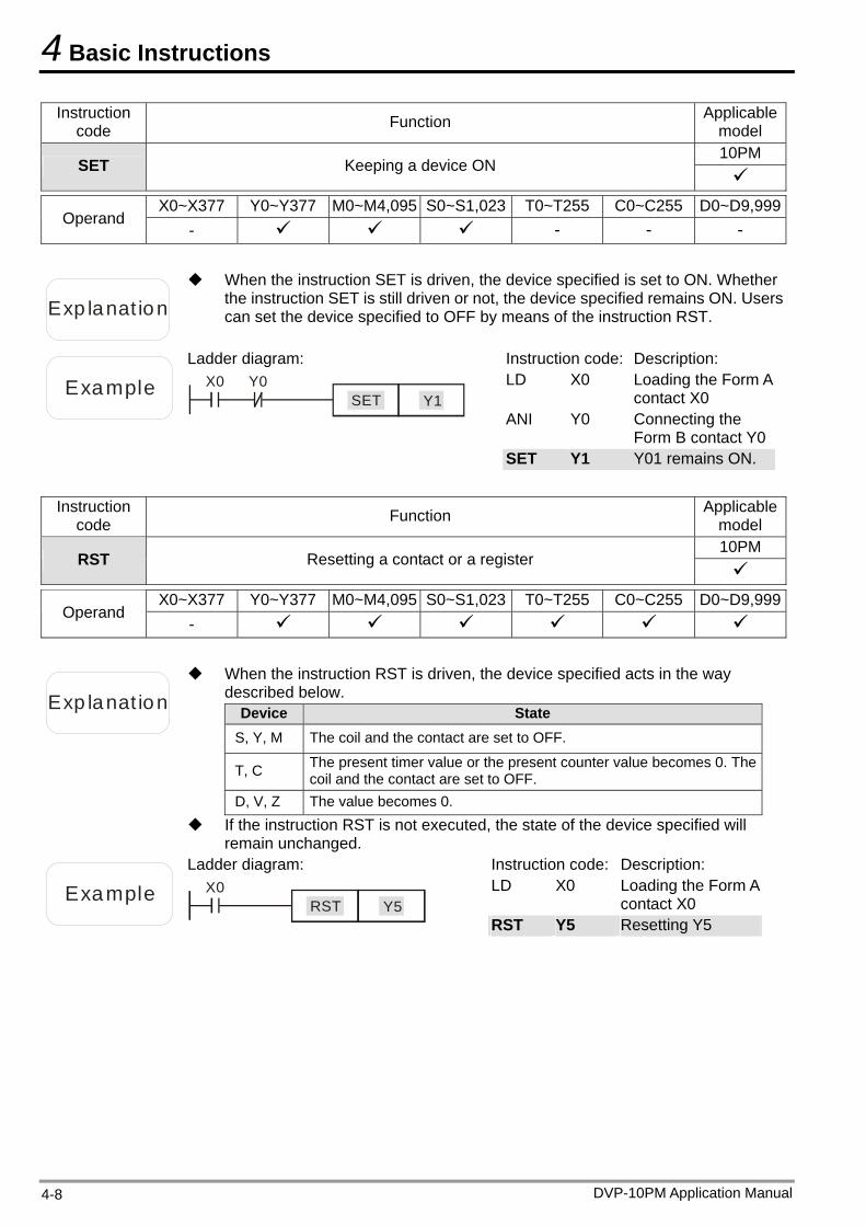
4 Basic Instructions
Instruction code Function Applicable
model 10PM
SET Keeping a device ON
X0~X377 Y0~Y377 M0~M4,095 S0~S1,023 T0~T255 C0~C255 D0~D9,999
Operand - - - -
Exp lanat ion
When the instruction SET is driven, the device specified is set to ON. Whether the instruction SET is still driven or not, the device specified remains ON. Users can set the device specified to OFF by means of the instruction RST.
Example
Ladder diagram: X0 Y0
Y1SET
Instruction code: Description: LD X0 Loading the Form A
contact X0 ANI Y0 Connecting the
Form B contact Y0SET Y1 Y01 remains ON.
Instruction
code Function Applicable model 10PM
RST Resetting a contact or a register
X0~X377 Y0~Y377 M0~M4,095 S0~S1,023 T0~T255 C0~C255 D0~D9,999
Operand -
Exp lanat ion
When the instruction RST is driven, the device specified acts in the way described below.
Device State S, Y, M The coil and the contact are set to OFF.
T, C The present timer value or the present counter value becomes 0. The coil and the contact are set to OFF.
D, V, Z The value becomes 0. If the instruction RST is not executed, the state of the device specified will
remain unchanged.
Example
Ladder diagram: X0
Y5RST
Instruction code: Description: LD X0 Loading the Form A
contact X0 RST Y5 Resetting Y5
DVP-10PM Application Manual 4-8
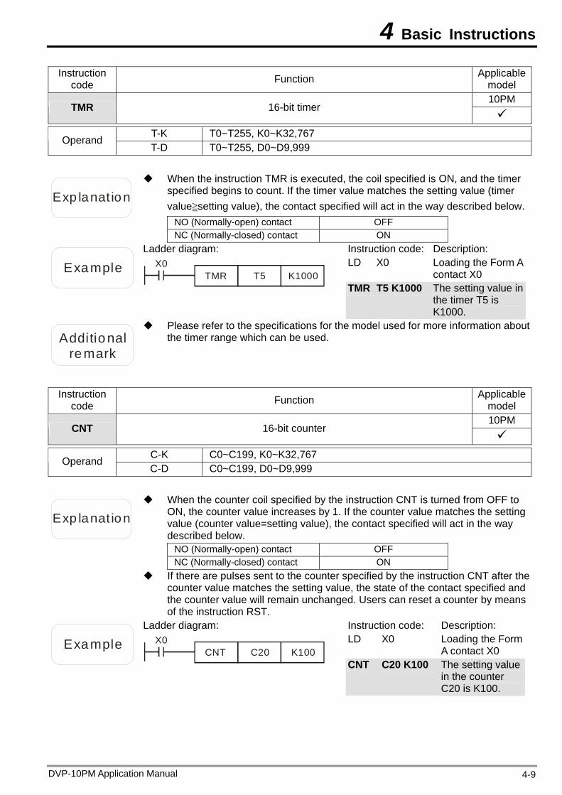
4 Basic Instructions
DVP-10PM Application Manual 4-9
Instruction code Function Applicable
model 10PM
TMR 16-bit timer
T-K T0~T255, K0~K32,767 Operand T-D T0~T255, D0~D9,999
Exp lanat ion
When the instruction TMR is executed, the coil specified is ON, and the timer specified begins to count. If the timer value matches the setting value (timer value≧setting value), the contact specified will act in the way described below.
NO (Normally-open) contact OFF NC (Normally-closed) contact ON
Example
Ladder diagram: X0
T5TMR K1000
Instruction code: Description: LD X0 Loading the Form A
contact X0 TMR T5 K1000 The setting value in
the timer T5 is K1000.
Additional
remark
Please refer to the specifications for the model used for more information about the timer range which can be used.
Instruction code Function Applicable
model 10PM
CNT 16-bit counter
C-K C0~C199, K0~K32,767 Operand C-D C0~C199, D0~D9,999
Exp lanat ion
When the counter coil specified by the instruction CNT is turned from OFF to ON, the counter value increases by 1. If the counter value matches the setting value (counter value=setting value), the contact specified will act in the way described below.
NO (Normally-open) contact OFF NC (Normally-closed) contact ON
If there are pulses sent to the counter specified by the instruction CNT after the counter value matches the setting value, the state of the contact specified and the counter value will remain unchanged. Users can reset a counter by means of the instruction RST.
Example
Ladder diagram: X0
C20CNT K100
Instruction code: Description: LD X0 Loading the Form
A contact X0 CNT C20 K100 The setting value
in the counter C20 is K100.
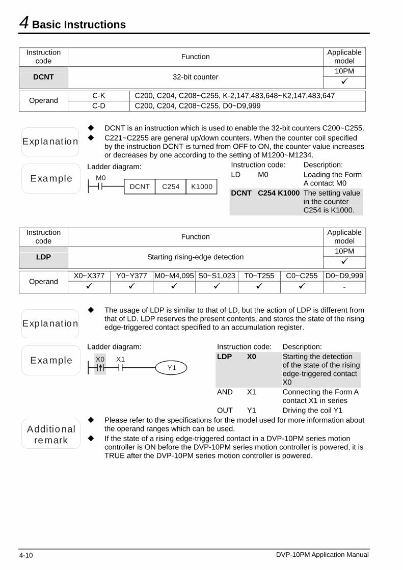
4 Basic Instructions
DVP-10PM Application Manual 4-10
Instruction code Function Applicable
model 10PM
DCNT 32-bit counter
C-K C200, C204, C208~C255, K-2,147,483,648~K2,147,483,647 Operand C-D C200, C204, C208~C255, D0~D9,999
Exp lanat ion C221~C2255 are general up/down counters. When the counter coil specified by the instruction DCNT is turned from OFF to ON, the counter value increases or decreases by one according to the setting of M1200~M1234.
DCNT is an instruction which is used to enable the 32-bit counters C200~C255.
Example
Ladder diagram: M0
C254DCNT K1000
Instruction code: Description: LD M0 Loading the Form
A contact M0 DCNT C254 K1000 The setting value
in the counter C254 is K1000.
Instruction
code Function Applicable model 10PM
LDP Starting rising-edge detection
X0~X377 Y0~Y377 M0~M4,095 S0~S1,023 T0~T255 C0~C255 D0~D9,999
Operand -
Exp lanat ion
The usage of LDP is similar to that of LD, but the action of LDP is different from that of LD. LDP reserves the present contents, and stores the state of the rising edge-triggered contact specified to an accumulation register.
Example
Ladder diagram:
X0 X1Y1
Instruction code: Description: LDP X0 Starting the detection
of the state of the rising edge-triggered contact X0
AND X1 Connecting the Form A contact X1 in series
OUT Y1 Driving the coil Y1
Additional
remark If the state of a rising edge-triggered contact in a DVP-10PM series motion controller is ON before the DVP-10PM series motion controller is powered, it is TRUE after the DVP-10PM series motion controller is powered.
Please refer to the specifications for the model used for more information about the operand ranges which can be used.
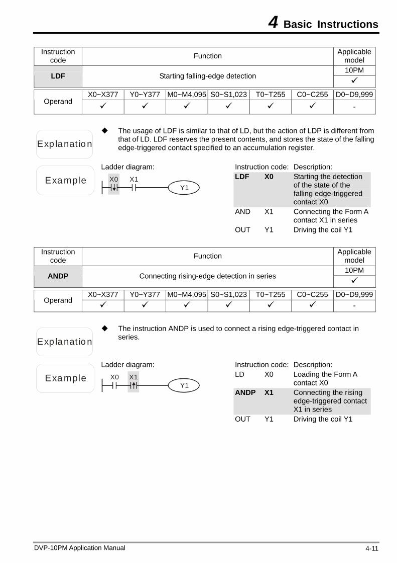
4 Basic Instructions
Instruction code Function Applicable
model 10PM
LDF Starting falling-edge detection
X0~X377 Y0~Y377 M0~M4,095 S0~S1,023 T0~T255 C0~C255 D0~D9,999
Operand -
Exp lanat ion
The usage of LDF is similar to that of LD, but the action of LDP is different from that of LD. LDF reserves the present contents, and stores the state of the falling edge-triggered contact specified to an accumulation register.
Example
Ladder diagram:
X0 X1Y1
Instruction code: Description: LDF X0 Starting the detection
of the state of the falling edge-triggered contact X0
AND X1 Connecting the Form A contact X1 in series
OUT Y1 Driving the coil Y1
Instruction code Function Applicable
model 10PM
ANDP Connecting rising-edge detection in series
X0~X377 Y0~Y377 M0~M4,095 S0~S1,023 T0~T255 C0~C255 D0~D9,999
Operand -
Exp lanat ion
The instruction ANDP is used to connect a rising edge-triggered contact in series.
Example
Ladder diagram:
X1X0Y1
Instruction code: Description: LD X0 Loading the Form A
contact X0 ANDP X1 Connecting the rising
edge-triggered contact X1 in series
OUT Y1 Driving the coil Y1
DVP-10PM Application Manual 4-11
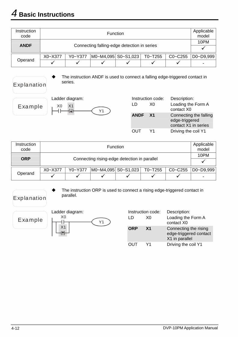
4 Basic Instructions
Instruction code Function Applicable
model 10PM
ANDF Connecting falling-edge detection in series
X0~X377 Y0~Y377 M0~M4,095 S0~S1,023 T0~T255 C0~C255 D0~D9,999
Operand -
Exp lanat ion
The instruction ANDF is used to connect a falling edge-triggered contact in series.
Example
Ladder diagram:
X1X0Y1
Instruction code: Description: LD X0 Loading the Form A
contact X0 ANDF X1 Connecting the falling
edge-triggered contact X1 in series
OUT Y1 Driving the coil Y1
Instruction code Function Applicable
model 10PM
ORP Connecting rising-edge detection in parallel
X0~X377 Y0~Y377 M0~M4,095 S0~S1,023 T0~T255 C0~C255 D0~D9,999
Operand -
Exp lanat ion
The instruction ORP is used to connect a rising edge-triggered contact in parallel.
Example
Ladder diagram: X0
X1Y1
Instruction code: Description: LD X0 Loading the Form A
contact X0 ORP X1 Connecting the rising
edge-triggered contact X1 in parallel
OUT Y1 Driving the coil Y1
DVP-10PM Application Manual 4-12
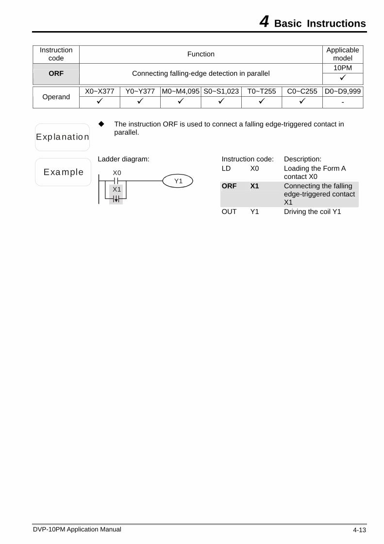
4 Basic Instructions
Instruction code Function Applicable
model 10PM
ORF Connecting falling-edge detection in parallel
X0~X377 Y0~Y377 M0~M4,095 S0~S1,023 T0~T255 C0~C255 D0~D9,999
Operand -
Exp lanat ion
The instruction ORF is used to connect a falling edge-triggered contact in parallel.
Example
Ladder diagram:
X0
X1Y1
Instruction code: Description: LD X0 Loading the Form A
contact X0 ORF X1 Connecting the falling
edge-triggered contact X1
OUT Y1 Driving the coil Y1
DVP-10PM Application Manual 4-13
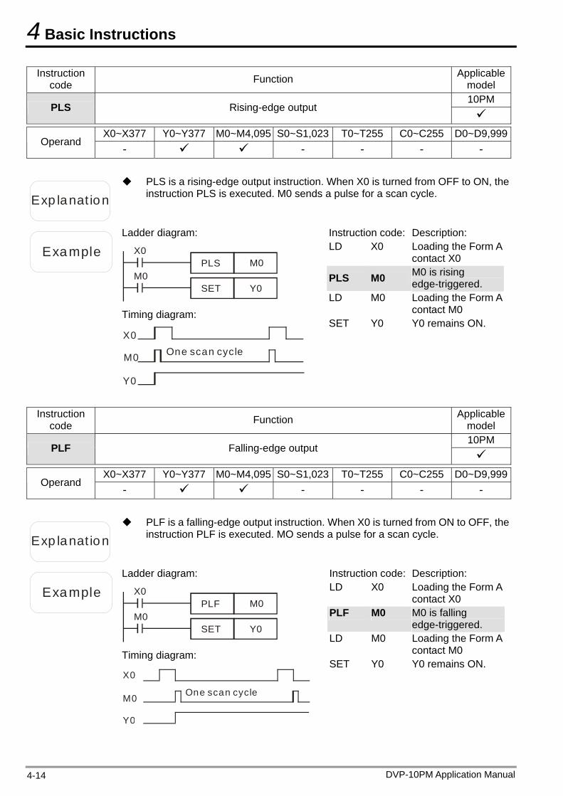
4 Basic Instructions
Instruction code Function Applicable
model 10PM
PLS Rising-edge output
X0~X377 Y0~Y377 M0~M4,095 S0~S1,023 T0~T255 C0~C255 D0~D9,999
Operand - - - - -
Exp lanat ion
PLS is a rising-edge output instruction. When X0 is turned from OFF to ON, the instruction PLS is executed. M0 sends a pulse for a scan cycle.
Example
Ladder diagram:
X0M0PLS
M0Y0SET
Timing diagram:
X0
M0
Y0
One scan cycle
Instruction code: Description: LD X0 Loading the Form A
contact X0
PLS M0 M0 is rising edge-triggered.
LD M0 Loading the Form A contact M0
SET Y0 Y0 remains ON.
Instruction code Function Applicable
model 10PM
PLF Falling-edge output
X0~X377 Y0~Y377 M0~M4,095 S0~S1,023 T0~T255 C0~C255 D0~D9,999
Operand - - - - -
Exp lanat ion
PLF is a falling-edge output instruction. When X0 is turned from ON to OFF, the instruction PLF is executed. MO sends a pulse for a scan cycle.
Example
Ladder diagram:
X0M0PLF
M0Y0SET
Timing diagram:
One scan cycle
X0
M0
Y0
Instruction code: Description: LD X0 Loading the Form A
contact X0 PLF M0 M0 is falling
edge-triggered. LD M0 Loading the Form A
contact M0 SET Y0 Y0 remains ON.
DVP-10PM Application Manual 4-14
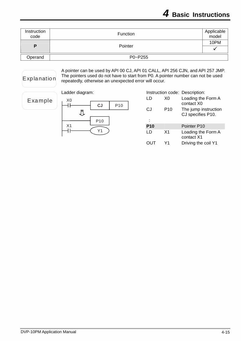
4 Basic Instructions
Instruction code Function Applicable
model 10PM
P Pointer
Operand P0~P255
Exp lanat ion
A pointer can be used by API 00 CJ, API 01 CALL, API 256 CJN, and API 257 JMP. The pointers used do not have to start from P0. A pointer number can not be used repeatedly, otherwise an unexpected error will occur.
Example
Ladder diagram:
X0
Y1
P10
X1P10
CJCJ
Instruction code: Description: LD X0 Loading the Form A
contact X0 CJ P10 The jump instruction
CJ specifies P10. :
P10 Pointer P10 LD X1 Loading the Form A
contact X1 OUT Y1 Driving the coil Y1
DVP-10PM Application Manual 4-15

4 Basic Instructions
DVP-10PM Application Manual 4-16
MEMO
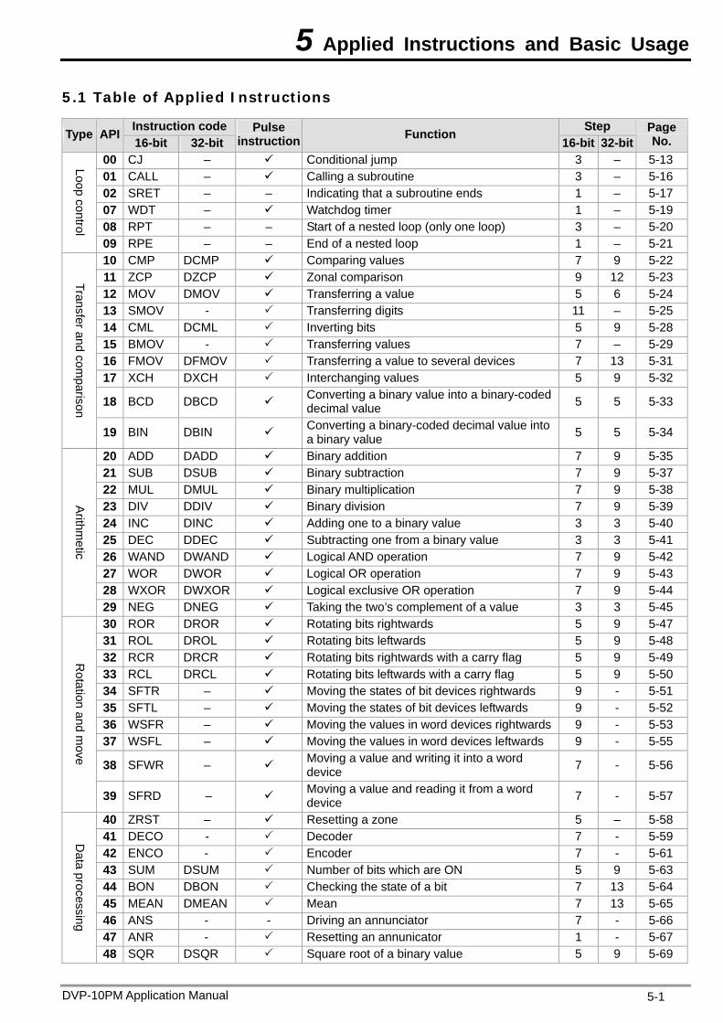
5 Applied Instructions and Basic Usage
5.1 Table of Applied Instructions
Instruction code Step Type API 16-bit 32-bit
Pulse instruction Function
16-bit 32-bitPage No.
00 CJ – Conditional jump 3 – 5-13 01 CALL – Calling a subroutine 3 – 5-16 02 SRET – – Indicating that a subroutine ends 1 – 5-17 07 WDT – Watchdog timer 1 – 5-19 08 RPT – – Start of a nested loop (only one loop) 3 – 5-20
Loop control
09 RPE – – End of a nested loop 1 – 5-21 10 CMP DCMP Comparing values 7 9 5-22 11 ZCP DZCP Zonal comparison 9 12 5-23 12 MOV DMOV Transferring a value 5 6 5-24 13 SMOV - Transferring digits 11 – 5-25 14 CML DCML Inverting bits 5 9 5-28 15 BMOV - Transferring values 7 – 5-29 16 FMOV DFMOV Transferring a value to several devices 7 13 5-31 17 XCH DXCH Interchanging values 5 9 5-32
18 BCD DBCD Converting a binary value into a binary-coded decimal value 5 5 5-33
Transfer and comparison
19 BIN DBIN Converting a binary-coded decimal value into a binary value 5 5 5-34
20 ADD DADD Binary addition 7 9 5-35 21 SUB DSUB Binary subtraction 7 9 5-37 22 MUL DMUL Binary multiplication 7 9 5-38 23 DIV DDIV Binary division 7 9 5-39 24 INC DINC Adding one to a binary value 3 3 5-40 25 DEC DDEC Subtracting one from a binary value 3 3 5-41 26 WAND DWAND Logical AND operation 7 9 5-42 27 WOR DWOR Logical OR operation 7 9 5-43 28 WXOR DWXOR Logical exclusive OR operation 7 9 5-44
Arithm
etic
29 NEG DNEG Taking the two’s complement of a value 3 3 5-45 30 ROR DROR Rotating bits rightwards 5 9 5-47 31 ROL DROL Rotating bits leftwards 5 9 5-48 32 RCR DRCR Rotating bits rightwards with a carry flag 5 9 5-49 33 RCL DRCL Rotating bits leftwards with a carry flag 5 9 5-50 34 SFTR – Moving the states of bit devices rightwards 9 - 5-51 35 SFTL – Moving the states of bit devices leftwards 9 - 5-52 36 WSFR – Moving the values in word devices rightwards 9 - 5-53 37 WSFL – Moving the values in word devices leftwards 9 - 5-55
38 SFWR – Moving a value and writing it into a word device 7 - 5-56
Rotation and m
ove
39 SFRD – Moving a value and reading it from a word device 7 - 5-57
40 ZRST – Resetting a zone 5 – 5-58 41 DECO - Decoder 7 - 5-59 42 ENCO - Encoder 7 - 5-61 43 SUM DSUM Number of bits which are ON 5 9 5-63 44 BON DBON Checking the state of a bit 7 13 5-64 45 MEAN DMEAN Mean 7 13 5-65 46 ANS - - Driving an annunciator 7 - 5-66 47 ANR - Resetting an annunicator 1 - 5-67
Data processing
48 SQR DSQR Square root of a binary value 5 9 5-69
DVP-10PM Application Manual 5-1

5 Applied Instructions and Basic Usage
DVP-10PM Application Manual 5-2
Instruction code Step Type API 16-bit 32-bit
Pulse instruction Function
16-bit 32-bitPage No.
Data
processing
49 – DFLT Converting a binary integer into a binary floating-point value – 6 5-70
High-speed
processing
50 REF - Refreshing the states of I/O devices 5 - 5-72
61 SER DSER Searching data 9 17 5-73 66 ALT - Alternating between ON and OFF 3 - 5-75 67 RAMP DRAMP - Ramp 9 17 5-76
Convenience 69 SORT DSORT - Sorting data 11 21 5-78
78 FROM DFROM Reading data from a control register in a special module 9 12 5-80
79 TO DTO Writing data into a control register in a special module 9 13 5-81
I/O
87 ABS DABS Absolute value 3 5 5-84 89 PLS – – Rising-edge output 3 – 4-14 90 LDP – – Starting rising-edge detection 3 – 4-10 91 LDF – – Starting falling-edge detection 3 – 4-11 92 ANDP – – Connecting rising-edge detection in series 3 – 4-11 93 ANDF – – Connecting falling-edge detection in series 3 – 4-12 94 ORP – – Connecting rising-edge detection in parallel 3 – 4-12 95 ORF – – Connecting falling-edge detection in parallel 3 – 4-13 96 TMR – – 16-bit timer 5 – 4-9 97 CNT DCNT – 16-bit counter 5 6 4-9
Basic instructions
99 PLF – – Falling-edge output 3 – 4-14
100 MODRD – – Reading Modbus data 7 – 5-85
Com
munication
101 MODWR – – Writing Modbus data 7 – 5-89
110 – DECMP Comparing binary floating-point values 7 9 5-94 111 – DEZCP Binary floating-point zonal comparison 9 12 5-95 112 – DMOVR Transferring a floating-point value 9 5-96 116 – DRAD Converting a degree to a radian – 6 5-97 117 – DDEG Converting a radian to a degree – 6 5-98 120 – DEADD Binary floating-point addition 7 9 5-99 121 – DESUB Binary floating-point subtraction 7 9 5-100122 – DEMUL Binary floating-point multiplication 7 9 5-101123 – DEDIV Binary floating-point division 7 9 5-102124 – DEXP Exponent of a binary floating-point value – 6 5-103
125 – DLN Natural logarithm of a binary floating-point value – 6 5-104
126 – DLOG Logarithm of a binary floating-point value – 9 5-105127 – DESQR Square root of a binary floating-point value 5 6 5-106128 – DPOW Power of a floating-point value – 9 5-107
129 – DINT Converting a binary floating-point value into a binary integer – 6 5-108
Floating-point value
130 – DSIN Sine of a binary floating-point value 5 6 5-109
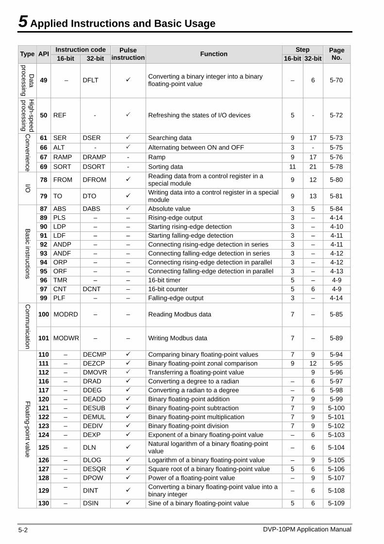
5 Applied Instructions and Basic Usage
DVP-10PM Application Manual 5-2
Instruction code Step Type API 16-bit 32-bit
Pulse instruction Function
16-bit 32-bitPage No.
Data
processing
49 – DFLT Converting a binary integer into a binary floating-point value – 6 5-70
High-speed
processing
50 REF - Refreshing the states of I/O devices 5 - 5-72
61 SER DSER Searching data 9 17 5-73 66 ALT - Alternating between ON and OFF 3 - 5-75 67 RAMP DRAMP - Ramp 9 17 5-76
Convenience 69 SORT DSORT - Sorting data 11 21 5-78
78 FROM DFROM Reading data from a control register in a special module 9 12 5-80 I/O
79 TO DTO Writing data into a control register in a special module 9 13 5-81
87 ABS DABS Absolute value 3 5 5-84 89 PLS – – Rising-edge output 3 – 4-14 90 LDP – – Starting rising-edge detection 3 – 4-10 91 LDF – – Starting falling-edge detection 3 – 4-11 92 ANDP – – Connecting rising-edge detection in series 3 – 4-11 93 ANDF – – Connecting falling-edge detection in series 3 – 4-12 94 ORP – – Connecting rising-edge detection in parallel 3 – 4-12 95 ORF – – Connecting falling-edge detection in parallel 3 – 4-13 96 TMR – – 16-bit timer 5 – 4-9 97 CNT DCNT – 16-bit counter 5 6 4-9
Basic instructions
99 PLF – – Falling-edge output 3 – 4-14
100 MODRD – – Reading Modbus data 7 – 5-85
Com
munication
101 MODWR – – Writing Modbus data 7 – 5-89
110 – DECMP Comparing binary floating-point values 7 9 5-94 111 – DEZCP Binary floating-point zonal comparison 9 12 5-95 112 – DMOVR Transferring a floating-point value 9 5-96 116 – DRAD Converting a degree to a radian – 6 5-97 117 – DDEG Converting a radian to a degree – 6 5-98 120 – DEADD Binary floating-point addition 7 9 5-99 121 – DESUB Binary floating-point subtraction 7 9 5-100122 – DEMUL Binary floating-point multiplication 7 9 5-101123 – DEDIV Binary floating-point division 7 9 5-102124 – DEXP Exponent of a binary floating-point value – 6 5-103
125 – DLN Natural logarithm of a binary floating-point value – 6 5-104
126 – DLOG Logarithm of a binary floating-point value – 9 5-105127 – DESQR Square root of a binary floating-point value 5 6 5-106128 – DPOW Power of a floating-point value – 9 5-107
129 – DINT Converting a binary floating-point value into a binary integer – 6 5-108
Floating-point value
130 – DSIN Sine of a binary floating-point value 5 6 5-109
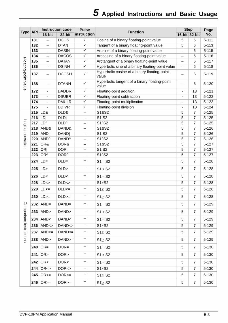
5 Applied Instructions and Basic Usage
DVP-10PM Application Manual 5-3
Instruction code Step Type API 16-bit 32-bit
Pulse instruction Function
16-bit 32-bitPage No.
131 – DCOS Cosine of a binary floating-point value 5 6 5-111 132 – DTAN Tangent of a binary floating-point value 5 6 5-113 133 – DASIN Arcsine of a binary floating-point value – 6 5-115 134 – DACOS Arccosine of a binary floating-point value – 6 5-116 135 – DATAN Arctangent of a binary floating-point value – 6 5-117 136 – DSINH Hyperbolic sine of a binary floating-point value – 6 5-118
137 – DCOSH Hyperbolic cosine of a binary floating-point value – 6 5-119
138 – DTANH Hyperbolic tangent of a binary floating-point value – 6 5-120
172 - DADDR Floating-point addition - 13 5-121173 - DSUBR Floating-point subtraction - 13 5-122174 - DMULR Floating-point multiplication - 13 5-123
Floating-point value
175 - DDIVR Floating-point division - 13 5-124215 LD& DLD& – S1&S2 5 7 5-125216 LD| DLD| – S1|S2 5 7 5-125217 LD^ DLD^ – S1^S2 5 7 5-125218 AND& DAND& – S1&S2 5 7 5-126219 AND| DAND| – S1|S2 5 7 5-126220 AND^ DAND^ – S1^S2 5 7 5-126221 OR& DOR& – S1&S2 5 7 5-127222 OR| DOR| – S1|S2 5 7 5-127
Logical operation
223 OR^ DOR^ – S1^S2 5 7 5-127
224 LD= DLD= – S1=S2 5 7 5-128
225 LD> DLD> – S1>S2 5 7 5-128
226 LD< DLD< – S1<S2 5 7 5-128
228 LD<> DLD<> – S1≠S2 5 7 5-128
229 LD<= DLD<= – S1≦ S2 5 7 5-128
230 LD>= DLD>= – S1≧ S2 5 7 5-128
232 AND= DAND= – S1=S2 5 7 5-129
233 AND> DAND> – S1>S2 5 7 5-129
234 AND< DAND< – S1<S2 5 7 5-129
236 AND<> DAND<> – S1≠S2 5 7 5-129
237 AND<= DAND<= – S1≦ S2 5 7 5-129
238 AND>= DAND>= – S1≧ S2 5 7 5-129
240 OR= DOR= – S1=S2 5 7 5-130
241 OR> DOR> – S1>S2 5 7 5-130
242 OR< DOR< – S1<S2 5 7 5-130
244 OR<> DOR<> – S1≠S2 5 7 5-130
245 OR<= DOR<= – S1≦ S2 5 7 5-130
Com
parison instructions
246 OR>= DOR>= – S1≧ S2 5 7 5-130
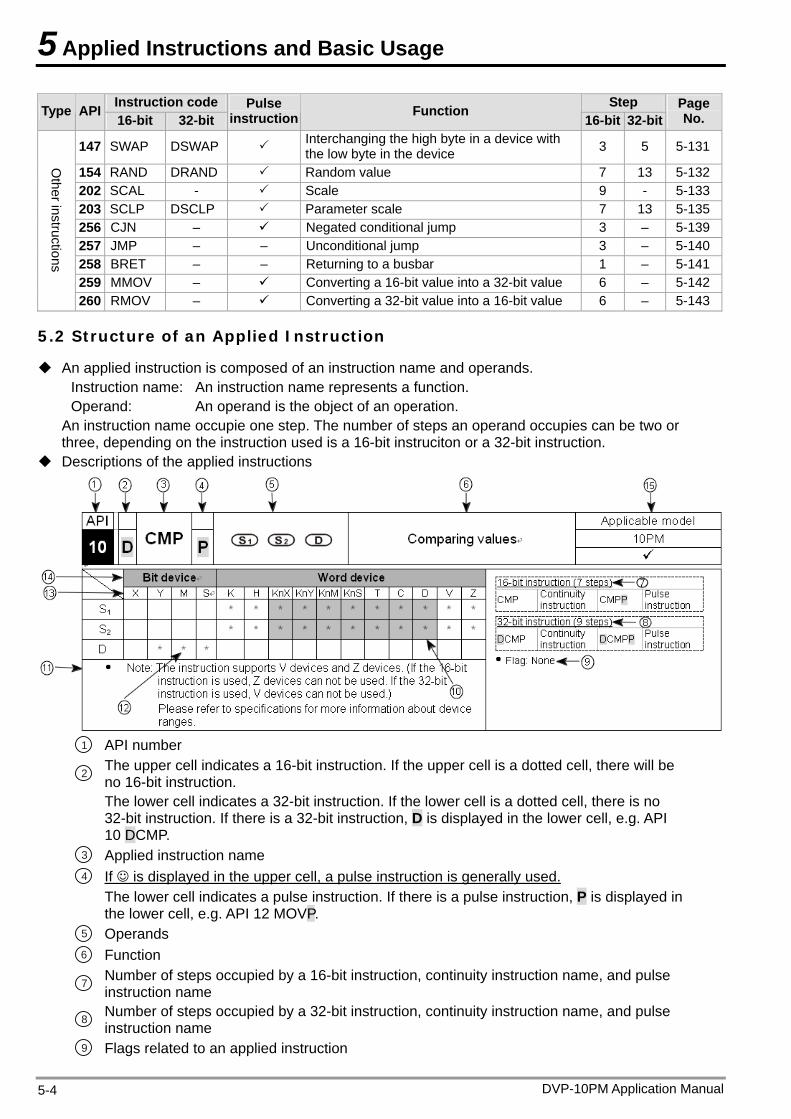
5 Applied Instructions and Basic Usage
DVP-10PM Application Manual 5-4
Instruction code Step Type API 16-bit 32-bit
Pulse instruction Function
16-bit 32-bitPage No.
147 SWAP DSWAP Interchanging the high byte in a device with the low byte in the device 3 5 5-131
154 RAND DRAND Random value 7 13 5-132202 SCAL - Scale 9 - 5-133203 SCLP DSCLP Parameter scale 7 13 5-135256 CJN – Negated conditional jump 3 – 5-139257 JMP – – Unconditional jump 3 – 5-140258 BRET – – Returning to a busbar 1 – 5-141259 MMOV – Converting a 16-bit value into a 32-bit value 6 – 5-142
Other instructions
260 RMOV – Converting a 32-bit value into a 16-bit value 6 – 5-143
5.2 Structure of an Applied Instruction
An applied instruction is composed of an instruction name and operands. Instruction name: An instruction name represents a function. Operand: An operand is the object of an operation.
An instruction name occupie one step. The number of steps an operand occupies can be two or three, depending on the instruction used is a 16-bit instruciton or a 32-bit instruction.
Descriptions of the applied instructions
1 API number
2 The upper cell indicates a 16-bit instruction. If the upper cell is a dotted cell, there will be no 16-bit instruction.
The lower cell indicates a 32-bit instruction. If the lower cell is a dotted cell, there is no 32-bit instruction. If there is a 32-bit instruction, D is displayed in the lower cell, e.g. API 10 DCMP.
3 Applied instruction name 4 If is displayed in the upper cell, a pulse instruction is generally used.
The lower cell indicates a pulse instruction. If there is a pulse instruction, P is displayed in the lower cell, e.g. API 12 MOVP.
5 Operands 6 Function
7 Number of steps occupied by a 16-bit instruction, continuity instruction name, and pulse instruction name
8 Number of steps occupied by a 32-bit instruction, continuity instruction name, and pulse instruction name
9 Flags related to an applied instruction
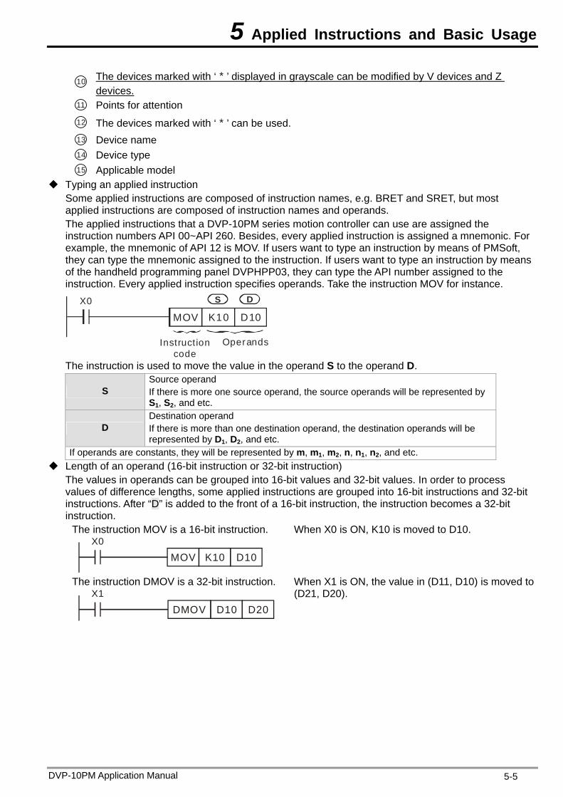
5 Applied Instructions and Basic Usage
10 The devices marked with ‘*’ displayed in grayscale can be modified by V devices and Z devices.
11 Points for attention 12 The devices marked with ‘*’ can be used. 13 Device name 14 Device type 15 Applicable model
Typing an applied instruction Some applied instructions are composed of instruction names, e.g. BRET and SRET, but most applied instructions are composed of instruction names and operands. The applied instructions that a DVP-10PM series motion controller can use are assigned the instruction numbers API 00~API 260. Besides, every applied instruction is assigned a mnemonic. For example, the mnemonic of API 12 is MOV. If users want to type an instruction by means of PMSoft, they can type the mnemonic assigned to the instruction. If users want to type an instruction by means of the handheld programming panel DVPHPP03, they can type the API number assigned to the instruction. Every applied instruction specifies operands. Take the instruction MOV for instance.
Instructioncode
Operands
X0
MOV K10 D10
S D
The instruction is used to move the value in the operand S to the operand D.
S Source operand If there is more one source operand, the source operands will be represented by S1, S2, and etc.
D Destination operand If there is more than one destination operand, the destination operands will be represented by D1, D2, and etc.
If operands are constants, they will be represented by m, m1, m2, n, n1, n2, and etc. Length of an operand (16-bit instruction or 32-bit instruction)
The values in operands can be grouped into 16-bit values and 32-bit values. In order to process values of difference lengths, some applied instructions are grouped into 16-bit instructions and 32-bit instructions. After “D” is added to the front of a 16-bit instruction, the instruction becomes a 32-bit instruction.
The instruction MOV is a 16-bit instruction. X0
MOV K10 D10
When X0 is ON, K10 is moved to D10.
The instruction DMOV is a 32-bit instruction. X1
D10 D20DMOV
When X1 is ON, the value in (D11, D10) is moved to (D21, D20).
DVP-10PM Application Manual 5-5
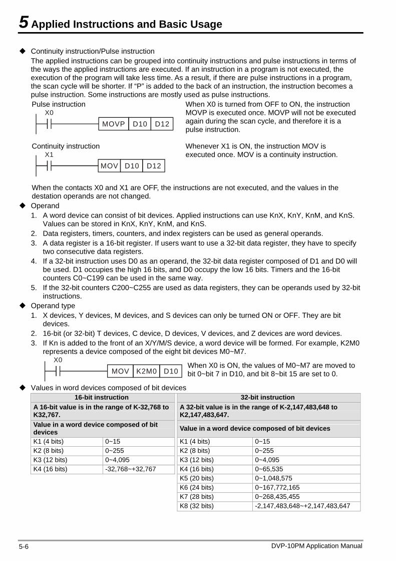
5 Applied Instructions and Basic Usage
Continuity instruction/Pulse instruction The applied instructions can be grouped into continuity instructions and pulse instructions in terms of the ways the applied instructions are executed. If an instruction in a program is not executed, the execution of the program will take less time. As a result, if there are pulse instructions in a program, the scan cycle will be shorter. If “P” is added to the back of an instruction, the instruction becomes a pulse instruction. Some instructions are mostly used as pulse instructions. Pulse instruction
X0
D10 D12MOVP
When X0 is turned from OFF to ON, the instruction MOVP is executed once. MOVP will not be executed again during the scan cycle, and therefore it is a pulse instruction.
Continuity instruction X1
MOV D10 D12
Whenever X1 is ON, the instruction MOV is executed once. MOV is a continuity instruction.
When the contacts X0 and X1 are OFF, the instructions are not executed, and the values in the destation operands are not changed.
Operand 1. A word device can consist of bit devices. Applied instructions can use KnX, KnY, KnM, and KnS.
Values can be stored in KnX, KnY, KnM, and KnS. 2. Data registers, timers, counters, and index registers can be used as general operands. 3. A data register is a 16-bit register. If users want to use a 32-bit data register, they have to specify
two consecutive data registers. 4. If a 32-bit instruction uses D0 as an operand, the 32-bit data register composed of D1 and D0 will
be used. D1 occupies the high 16 bits, and D0 occupy the low 16 bits. Timers and the 16-bit counters C0~C199 can be used in the same way.
5. If the 32-bit counters C200~C255 are used as data registers, they can be operands used by 32-bit instructions.
Operand type 1. X devices, Y devices, M devices, and S devices can only be turned ON or OFF. They are bit
devices. 2. 16-bit (or 32-bit) T devices, C device, D devices, V devices, and Z devices are word devices. 3. If Kn is added to the front of an X/Y/M/S device, a word device will be formed. For example, K2M0
represents a device composed of the eight bit devices M0~M7. X0
K2M0 D10MOVWhen X0 is ON, the values of M0~M7 are moved to bit 0~bit 7 in D10, and bit 8~bit 15 are set to 0.
Values in word devices composed of bit devices 16-bit instruction 32-bit instruction
A 16-bit value is in the range of K-32,768 to K32,767.
A 32-bit value is in the range of K-2,147,483,648 to K2,147,483,647.
Value in a word device composed of bit devices Value in a word device composed of bit devices
K1 (4 bits) 0~15 K1 (4 bits) 0~15 K2 (8 bits) 0~255 K2 (8 bits) 0~255 K3 (12 bits) 0~4,095 K3 (12 bits) 0~4,095 K4 (16 bits) -32,768~+32,767 K4 (16 bits) 0~65,535
K5 (20 bits) 0~1,048,575 K6 (24 bits) 0~167,772,165 K7 (28 bits) 0~268,435,455
K8 (32 bits) -2,147,483,648~+2,147,483,647
DVP-10PM Application Manual 5-6
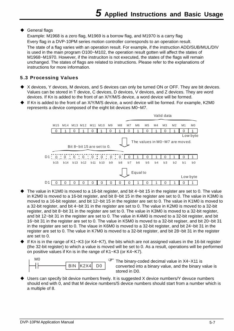
5 Applied Instructions and Basic Usage
General flags Example: M1968 is a zero flag, M1969 is a borrow flag, and M1970 is a carry flag Every flag in a DVP-10PM series motion controller corresponds to an operation result. The state of a flag varies with an operation result. For example, if the instruction ADD/SUB/MUL/DIV is used in the main program O100~M102, the operation result gotten will affect the states of M1968~M1970. However, if the instruciton is not executed, the states of the flags will remain unchanged. The states of flags are related to instructions. Please refer to the explanations of instructions for more information.
5.3 Processing Values
X devices, Y devices, M devices, and S devices can only be turned ON or OFF. They are bit devices. Values can be stored in T device, C devices, D devices, V devices, and Z devices. They are word devices. If Kn is added to the front of an X/Y/M/S device, a word device will be formed.
If Kn is added to the front of an X/Y/M/S device, a word device will be formed. For example, K2M0 represents a device composed of the eight bit devices M0~M7.
M15 M14 M13 M12 M11 M10 M9 M8 M7 M6 M5 M4 M3 M2 M0M1
The values in M0~M7 are moved.
Equal to
Bit 8~ bit 15 are set to 0.
0 0 0 0 0 0 0 0
0000 1 1 1 1
11111111
D1
Low byte
D1 1111 000000000000
b15 b14 b13 b12 b11 b10 b9 b8 b7 b6 b5 b4 b3 b2 b0b1
00000000
Valid data
Low byte
The value in K1M0 is moved to a 16-bit register, and bit 4~bit 15 in the register are set to 0. The value
in K2M0 is moved to a 16-bit register, and bit 8~bit 15 in the register are set to 0. The value in K3M0 is moved to a 16-bit register, and bit 12~bit 15 in the register are set to 0. The value in K1M0 is moved to a 32-bit register, and bit 4~bit 31 in the register are set to 0. The value in K2M0 is moved to a 32-bit register, and bit 8~bit 31 in the register are set to 0. The value in K3M0 is moved to a 32-bit register, and bit 12~bit 31 in the register are set to 0. The value in K4M0 is moved to a 32-bit register, and bit 16~bit 31 in the register are set to 0. The value in K5M0 is moved to a 32-bit regiser, and bit 20~bit 31 in the register are set to 0. The vlaue in K6M0 is moved to a 32-bit register, and bit 24~bit 31 in the register are set to 0. The value in K7M0 is moved to a 32-bit register, and bit 28~bit 31 in the register are set to 0.
If Kn is in the range of K1~K3 (or K4~K7), the bits which are not assigned values in the 16-bit register (the 32-bit register) to which a value is moved will be set to 0. As a result, operations will be performed on positive values if Kn is in the range of K1~K3 (or K4~K7).
M0
BIN K2X4 D0 The binary-coded decimal value in X4~X11 is
converted into a binary value, and the binary value is stored in D0.
Users can specify bit device numbers freely. It is suggested X device numbers/Y devuce numbers should end with 0, and that M device numbers/S device numbers should start from a number which is a multiple of 8.
DVP-10PM Application Manual 5-7
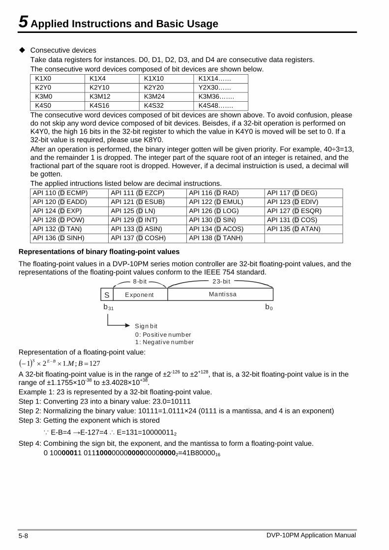
5 Applied Instructions and Basic Usage
Consecutive devices Take data registers for instances. D0, D1, D2, D3, and D4 are consecutive data registers. The consecutive word devices composed of bit devices are shown below.
K1X0 K1X4 K1X10 K1X14…… K2Y0 K2Y10 K2Y20 Y2X30…… K3M0 K3M12 K3M24 K3M36……. K4S0 K4S16 K4S32 K4S48…….
The consecutive word devices composed of bit devices are shown above. To avoid confusion, please do not skip any word device composed of bit devices. Beisdes, if a 32-bit operation is performed on K4Y0, the high 16 bits in the 32-bit register to which the value in K4Y0 is moved will be set to 0. If a 32-bit value is required, please use K8Y0. After an operation is performed, the binary integer gotten will be given priority. For example, 40÷3=13, and the remainder 1 is dropped. The integer part of the square root of an integer is retained, and the fractional part of the square root is dropped. However, if a decimal instruiction is used, a decimal will be gotten. The applied intructions listed below are decimal instructions. API 110 (D ECMP) API 111 (D EZCP) API 116 (D RAD) API 117 (D DEG) API 120 (D EADD) API 121 (D ESUB) API 122 (D EMUL) API 123 (D EDIV) API 124 (D EXP) API 125 (D LN) API 126 (D LOG) API 127 (D ESQR) API 128 (D POW) API 129 (D INT) API 130 (D SIN) API 131 (D COS) API 132 (D TAN) API 133 (D ASIN) API 134 (D ACOS) API 135 (D ATAN) API 136 (D SINH) API 137 (D COSH) API 138 (D TANH)
Representations of binary floating-point values The floating-point values in a DVP-10PM series motion controller are 32-bit floating-point values, and the representations of the floating-point values conform to the IEEE 754 standard.
S Exponent Mantissa
8-b it 23-bi t
b31 b0
Sign b it0 : Positive number1: Negative number
Representation of a floating-point value: 127;.121 BMBES A 32-bit floating-point value is in the range of ±2-126 to ±2+128, that is, a 32-bit floating-point value is in the range of ±1.1755×10-38 to ±3.4028×10+38. Example 1: 23 is represented by a 32-bit floating-point value. Step 1: Converting 23 into a binary value: 23.0=10111 Step 2: Normalizing the binary value: 10111=1.0111×24 (0111 is a mantissa, and 4 is an exponent) Step 3: Getting the exponent which is stored
∵ E-B=4 →E-127=4 ∴ E=131=100000112 Step 4: Combining the sign bit, the exponent, and the mantissa to form a floating-point value.
0 10000011 011100000000000000000002=41B8000016
DVP-10PM Application Manual 5-8
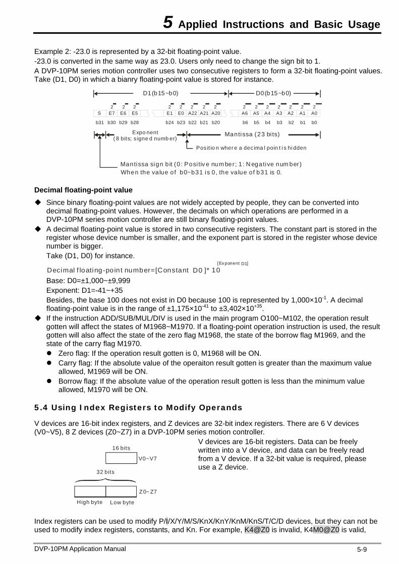
5 Applied Instructions and Basic Usage
Example 2: -23.0 is represented by a 32-bit floating-point value. -23.0 is converted in the same way as 23.0. Users only need to change the sign bit to 1. A DVP-10PM series motion controller uses two consecutive registers to form a 32-bit floating-point values. Take (D1, D0) in which a bianry floating-point value is stored for instance.
S E7 E6 E5 E1 E0 A22 A21 A20 A6 A5 A4 A3 A2 A1 A0
b0b1b2b3b4b5b6b20b21b22b23b24b28b29b30b31
2 2 2 2 2 2 2 2 2 2 2 2 22 2
D1(b15~b0) D0(b15~b0)
Expo nent ( 8 bits; s igne d numb er)
Mantissa (23 bi ts)
Mantissa sign b it (0 : Posi tiv e num ber; 1 : N egative num ber)When the va lue of b0~b31 is 0 , the va lue of b31 is 0.
Pos it io n wher e a dec ima l poin t i s hi dden
Decimal floating-point value Since binary floating-point values are not widely accepted by people, they can be converted into
decimal floating-point values. However, the decimals on which operations are performed in a DVP-10PM series motion controller are still binary floating-point values.
A decimal floating-point value is stored in two consecutive registers. The constant part is stored in the register whose device number is smaller, and the exponent part is stored in the register whose device number is bigger. Take (D1, D0) for instance.
10Decimal f loating-point number=[Constant ]*D0[Exponent ]D1
Base: D0=±1,000~±9,999
Exponent: D1=-41~+35 Besides, the base 100 does not exist in D0 because 100 is represented by 1,000×10-1. A decimal floating-point value is in the range of ±1,175×10-41 to ±3,402×10+35.
If the instruction ADD/SUB/MUL/DIV is used in the main program O100~M102, the operation result gotten will affect the states of M1968~M1970. If a floating-point operation instruction is used, the result gotten will also affect the state of the zero flag M1968, the state of the borrow flag M1969, and the state of the carry flag M1970. Zero flag: If the operation result gotten is 0, M1968 will be ON. Carry flag: If the absolute value of the operaiton result gotten is greater than the maximum value
allowed, M1969 will be ON. Borrow flag: If the absolute value of the operation result gotten is less than the minimum value
allowed, M1970 will be ON.
5.4 Using Index Registers to Modify Operands
V devices are 16-bit index registers, and Z devices are 32-bit index registers. There are 6 V devices (V0~V5), 8 Z devices (Z0~Z7) in a DVP-10PM series motion controller.
V0~V7
Z0~ Z7
32 bits
High byte Low byte
16 bits
V devices are 16-bit registers. Data can be freely written into a V device, and data can be freely read from a V device. If a 32-bit value is required, please use a Z device.
Index registers can be used to modify P/I/X/Y/M/S/KnX/KnY/KnM/KnS/T/C/D devices, but they can not be used to modify index registers, constants, and Kn. For example, K4@Z0 is invalid, K4M0@Z0 is valid,
DVP-10PM Application Manual 5-9
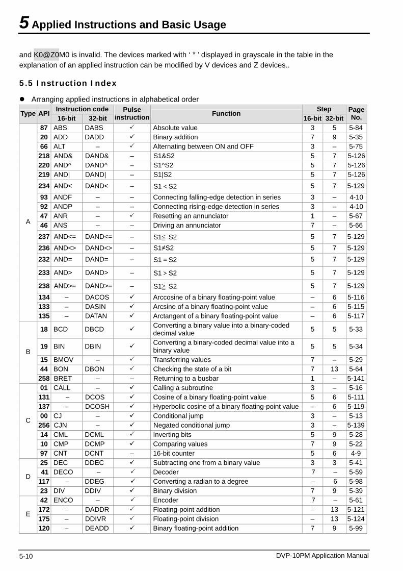
5 Applied Instructions and Basic Usage
and K0@Z0M0 is invalid. The devices marked with ‘*’ displayed in grayscale in the table in the explanation of an applied instruction can be modified by V devices and Z devices..
5.5 Instruction Index
Arranging applied instructions in alphabetical order Instruction code Step Type API 16-bit 32-bit
Pulse instruction Function
16-bit 32-bitPage No.
87 ABS DABS Absolute value 3 5 5-8420 ADD DADD Binary addition 7 9 5-3566 ALT – Alternating between ON and OFF 3 – 5-75218 AND& DAND& – S1&S2 5 7 5-126220 AND^ DAND^ – S1^S2 5 7 5-126219 AND| DAND| – S1|S2 5 7 5-126
234 AND< DAND< – S1<S2 5 7 5-129
93 ANDF – – Connecting falling-edge detection in series 3 – 4-1092 ANDP – – Connecting rising-edge detection in series 3 – 4-1047 ANR – Resetting an annunciator 1 – 5-6746 ANS – – Driving an annunciator 7 – 5-66
237 AND<= DAND<= – S1≦ S2 5 7 5-129
236 AND<> DAND<> – S1≠S2 5 7 5-129
232 AND= DAND= – S1=S2 5 7 5-129
233 AND> DAND> – S1>S2 5 7 5-129
238 AND>= DAND>= – S1≧ S2 5 7 5-129
134 – DACOS Arccosine of a binary floating-point value – 6 5-116133 – DASIN Arcsine of a binary floating-point value – 6 5-115
A
135 – DATAN Arctangent of a binary floating-point value – 6 5-117
18 BCD DBCD Converting a binary value into a binary-coded decimal value 5 5 5-33
19 BIN DBIN Converting a binary-coded decimal value into a binary value 5 5 5-34
15 BMOV – Transferring values 7 – 5-2944 BON DBON Checking the state of a bit 7 13 5-64
B
258 BRET – – Returning to a busbar 1 – 5-14101 CALL – Calling a subroutine 3 – 5-16131 – DCOS Cosine of a binary floating-point value 5 6 5-111137 – DCOSH Hyperbolic cosine of a binary floating-point value – 6 5-11900 CJ – Conditional jump 3 – 5-13256 CJN – Negated conditional jump 3 – 5-13914 CML DCML Inverting bits 5 9 5-2810 CMP DCMP Comparing values 7 9 5-22
C
97 CNT DCNT – 16-bit counter 5 6 4-925 DEC DDEC Subtracting one from a binary value 3 3 5-4141 DECO – Decoder 7 – 5-59
117 – DDEG Converting a radian to a degree – 6 5-98D
23 DIV DDIV Binary division 7 9 5-3942 ENCO – Encoder 7 – 5-61172 – DADDR Floating-point addition – 13 5-121175 – DDIVR Floating-point division – 13 5-124
E
120 – DEADD Binary floating-point addition 7 9 5-99
DVP-10PM Application Manual 5-10
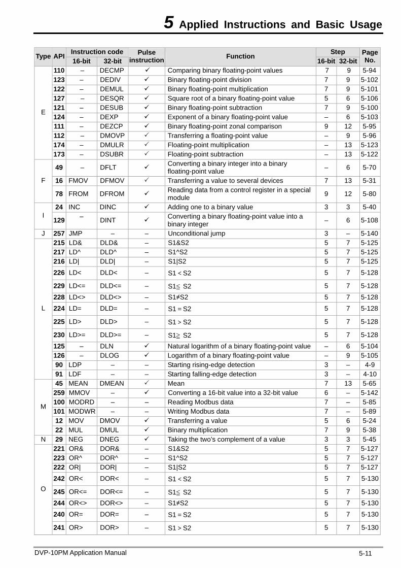
5 Applied Instructions and Basic Usage
DVP-10PM Application Manual 5-11
Instruction code Step Type API 16-bit 32-bit
Pulse instruction Function
16-bit 32-bitPage No.
110 – DECMP Comparing binary floating-point values 7 9 5-94123 – DEDIV Binary floating-point division 7 9 5-102122 – DEMUL Binary floating-point multiplication 7 9 5-101127 – DESQR Square root of a binary floating-point value 5 6 5-106121 – DESUB Binary floating-point subtraction 7 9 5-100124 – DEXP Exponent of a binary floating-point value – 6 5-103111 – DEZCP Binary floating-point zonal comparison 9 12 5-95112 – DMOVP Transferring a floating-point value – 9 5-96174 – DMULR Floating-point multiplication – 13 5-123
E
173 – DSUBR Floating-point subtraction – 13 5-122
49 – DFLT Converting a binary integer into a binary floating-point value – 6 5-70
16 FMOV DFMOV Transferring a value to several devices 7 13 5-31F
78 FROM DFROM Reading data from a control register in a special module 9 12 5-80
24 INC DINC Adding one to a binary value 3 3 5-40I
129 – DINT Converting a binary floating-point value into a binary integer – 6 5-108
J 257 JMP – – Unconditional jump 3 – 5-140215 LD& DLD& – S1&S2 5 7 5-125217 LD^ DLD^ – S1^S2 5 7 5-125216 LD| DLD| – S1|S2 5 7 5-125
226 LD< DLD< – S1<S2 5 7 5-128
229 LD<= DLD<= – S1≦ S2 5 7 5-128
228 LD<> DLD<> – S1≠S2 5 7 5-128
224 LD= DLD= – S1=S2 5 7 5-128
225 LD> DLD> – S1>S2 5 7 5-128
230 LD>= DLD>= – S1≧ S2 5 7 5-128
125 – DLN Natural logarithm of a binary floating-point value – 6 5-104126 – DLOG Logarithm of a binary floating-point value – 9 5-10590 LDP – – Starting rising-edge detection 3 – 4-9
L
91 LDF – – Starting falling-edge detection 3 – 4-1045 MEAN DMEAN Mean 7 13 5-65259 MMOV – Converting a 16-bit value into a 32-bit value 6 – 5-142100 MODRD – – Reading Modbus data 7 – 5-85101 MODWR – – Writing Modbus data 7 – 5-8912 MOV DMOV Transferring a value 5 6 5-24
M
22 MUL DMUL Binary multiplication 7 9 5-38N 29 NEG DNEG Taking the two’s complement of a value 3 3 5-45
221 OR& DOR& – S1&S2 5 7 5-127223 OR^ DOR^ – S1^S2 5 7 5-127222 OR| DOR| – S1|S2 5 7 5-127
242 OR< DOR< – S1<S2 5 7 5-130
245 OR<= DOR<= – S1≦ S2 5 7 5-130
244 OR<> DOR<> – S1≠S2 5 7 5-130
240 OR= DOR= – S1=S2 5 7 5-130
O
241 OR> DOR> – S1>S2 5 7 5-130
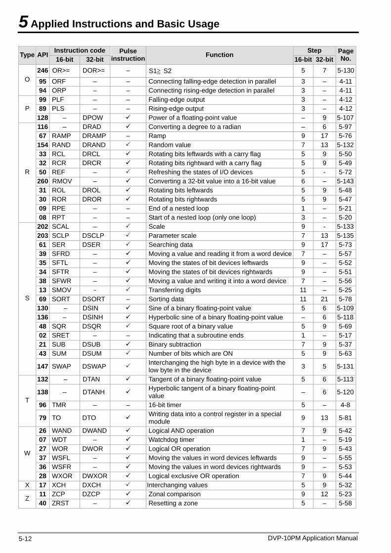
5 Applied Instructions and Basic Usage
Instruction code Step Type API 16-bit 32-bit
Pulse instruction Function
16-bit 32-bitPage No.
246 OR>= DOR>= – S1≧ S2 5 7 5-130
95 ORF – – Connecting falling-edge detection in parallel 3 – 4-11O
94 ORP – – Connecting rising-edge detection in parallel 3 – 4-1199 PLF – – Falling-edge output 3 – 4-1289 PLS – – Rising-edge output 3 – 4-12P 128 – DPOW Power of a floating-point value – 9 5-107116 – DRAD Converting a degree to a radian – 6 5-9767 RAMP DRAMP – Ramp 9 17 5-76154 RAND DRAND Random value 7 13 5-13233 RCL DRCL Rotating bits leftwards with a carry flag 5 9 5-5032 RCR DRCR Rotating bits rightward with a carry flag 5 9 5-4950 REF – Refreshing the states of I/O devices 5 - 5-72260 RMOV – Converting a 32-bit value into a 16-bit value 6 – 5-14331 ROL DROL Rotating bits leftwards 5 9 5-4830 ROR DROR Rotating bits rightwards 5 9 5-4709 RPE – – End of a nested loop 1 – 5-21
R
08 RPT – – Start of a nested loop (only one loop) 3 – 5-20202 SCAL – Scale 9 - 5-133203 SCLP DSCLP Parameter scale 7 13 5-13561 SER DSER Searching data 9 17 5-7339 SFRD – Moving a value and reading it from a word device 7 – 5-5735 SFTL – Moving the states of bit devices leftwards 9 – 5-5234 SFTR – Moving the states of bit devices rightwards 9 – 5-5138 SFWR – Moving a value and writing it into a word device 7 – 5-5613 SMOV - Transferring digits 11 – 5-2569 SORT DSORT – Sorting data 11 21 5-78130 – DSIN Sine of a binary floating-point value 5 6 5-109136 – DSINH Hyperbolic sine of a binary floating-point value – 6 5-11848 SQR DSQR Square root of a binary value 5 9 5-6902 SRET – – Indicating that a subroutine ends 1 – 5-1721 SUB DSUB Binary subtraction 7 9 5-3743 SUM DSUM Number of bits which are ON 5 9 5-63
S
147 SWAP DSWAP Interchanging the high byte in a device with the low byte in the device 3 5 5-131
132 – DTAN Tangent of a binary floating-point value 5 6 5-113
138 – DTANH Hyperbolic tangent of a binary floating-point value – 6 5-120
96 TMR – – 16-bit timer 5 – 4-8T
79 TO DTO Writing data into a control register in a special module 9 13 5-81
26 WAND DWAND Logical AND operation 7 9 5-4207 WDT – Watchdog timer 1 – 5-1927 WOR DWOR Logical OR operation 7 9 5-4337 WSFL – Moving the values in word devices leftwards 9 – 5-5536 WSFR – Moving the values in word devices rightwards 9 – 5-53
W
28 WXOR DWXOR Logical exclusive OR operation 7 9 5-44X 17 XCH DXCH Interchanging values 5 9 5-32
11 ZCP DZCP Zonal comparison 9 12 5-23Z 40 ZRST – Resetting a zone 5 – 5-58
DVP-10PM Application Manual 5-12
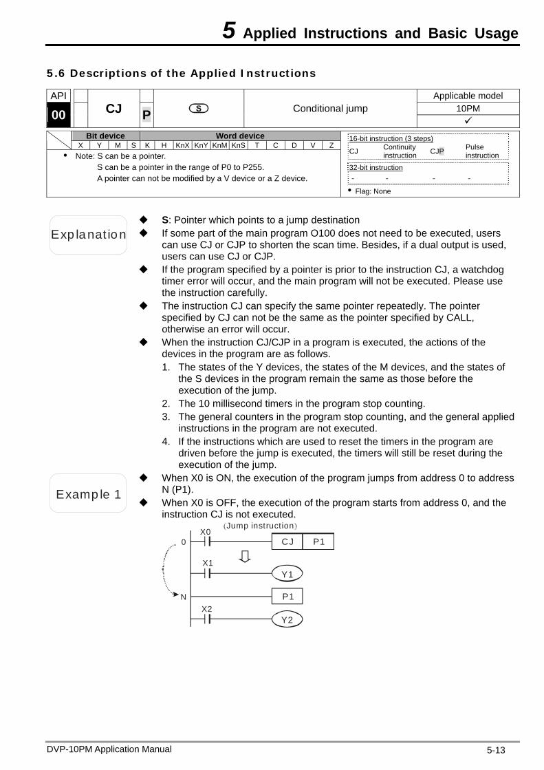
5 Applied Instructions and Basic Usage
5.6 Descriptions of the Applied Instructions
API Applicable model 10PM 00
CJ P Conditional jump
Bit device Word device X Y M S K H KnX KnY KnM KnS T C D V Z
Note: S can be a pointer. S can be a pointer in the range of P0 to P255. A pointer can not be modified by a V device or a Z device.
16-bit instruction (3 steps) CJ Continuity
instruction CJP Pulse instruction
32-bit instruction - - - -
Flag: None
Exp lanat ion If some part of the main program O100 does not need to be executed, users can use CJ or CJP to shorten the scan time. Besides, if a dual output is used, users can use CJ or CJP.
S: Pointer which points to a jump destination
If the program specified by a pointer is prior to the instruction CJ, a watchdog timer error will occur, and the main program will not be executed. Please use the instruction carefully.
The instruction CJ can specify the same pointer repeatedly. The pointer specified by CJ can not be the same as the pointer specified by CALL, otherwise an error will occur.
When the instruction CJ/CJP in a program is executed, the actions of the devices in the program are as follows. 1. The states of the Y devices, the states of the M devices, and the states of
the S devices in the program remain the same as those before the execution of the jump.
2. The 10 millisecond timers in the program stop counting. 3. The general counters in the program stop counting, and the general applied
instructions in the program are not executed. 4. If the instructions which are used to reset the timers in the program are
driven before the jump is executed, the timers will still be reset during the execution of the jump.
Examp le 1
When X0 is ON, the execution of the program jumps from address 0 to address N (P1).
When X0 is OFF, the execution of the program starts from address 0, and the instruction CJ is not executed.
X0
X1
X2
CJ P1
Y1
Y2
0
N
( )Jump instruction
P1
DVP-10PM Application Manual 5-13
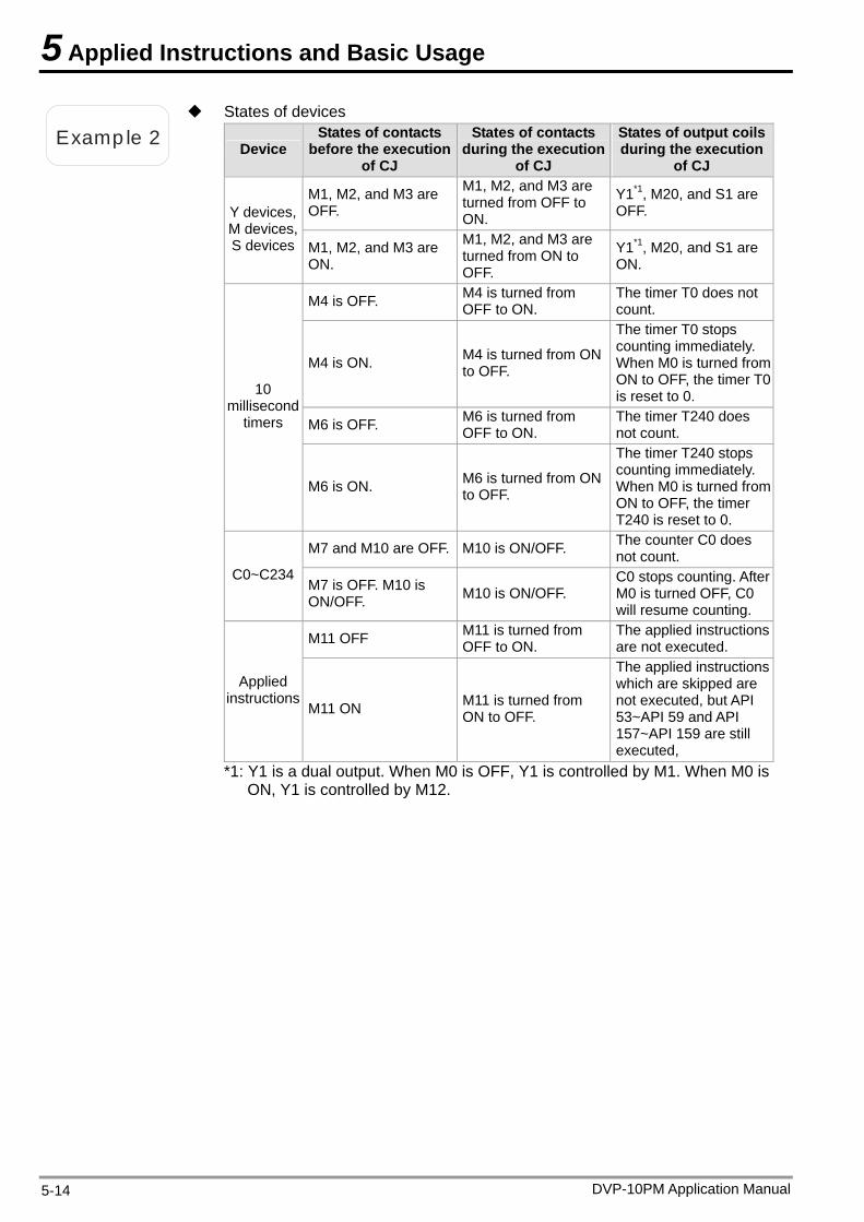
5 Applied Instructions and Basic Usage
Examp le 2
States of devices
Device States of contacts
before the execution of CJ
States of contacts during the execution
of CJ
States of output coils during the execution
of CJ
M1, M2, and M3 are OFF.
M1, M2, and M3 are turned from OFF to ON.
Y1*1, M20, and S1 are OFF. Y devices,
M devices, S devices M1, M2, and M3 are
ON.
M1, M2, and M3 are turned from ON to OFF.
Y1*1, M20, and S1 are ON.
M4 is OFF. M4 is turned from OFF to ON.
The timer T0 does not count.
M4 is ON. M4 is turned from ON to OFF.
The timer T0 stops counting immediately. When M0 is turned from ON to OFF, the timer T0 is reset to 0.
M6 is OFF. M6 is turned from OFF to ON.
The timer T240 does not count.
10 millisecond
timers
M6 is ON. M6 is turned from ON to OFF.
The timer T240 stops counting immediately. When M0 is turned from ON to OFF, the timer T240 is reset to 0.
M7 and M10 are OFF. M10 is ON/OFF. The counter C0 does not count.
C0~C234 M7 is OFF. M10 is ON/OFF. M10 is ON/OFF.
C0 stops counting. After M0 is turned OFF, C0 will resume counting.
M11 OFF M11 is turned from OFF to ON.
The applied instructions are not executed.
Applied instructions
M11 ON M11 is turned from ON to OFF.
The applied instructions which are skipped are not executed, but API 53~API 59 and API 157~API 159 are still executed,
*1: Y1 is a dual output. When M0 is OFF, Y1 is controlled by M1. When M0 is ON, Y1 is controlled by M12.
DVP-10PM Application Manual 5-14
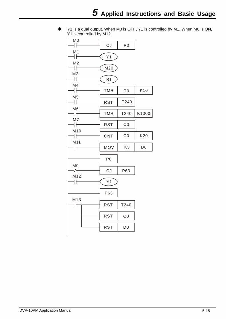
5 Applied Instructions and Basic Usage
Y1 is a dual output. When M0 is OFF, Y1 is controlled by M1. When M0 is ON, Y1 is controlled by M12.
CJ P0M0
M1
M2
M3
M4
M5
M6
M7
M10
M11
M0
M12
M13
RST
RST
RST T240
C0
D0
Y1
CJ P63
S1
TMR T0 K10
TMR
RST
RST
CNT
MOV
T240
T240
C0
C0
D0K3
K20
Y1
M20
K1000
P0
P63
DVP-10PM Application Manual 5-15
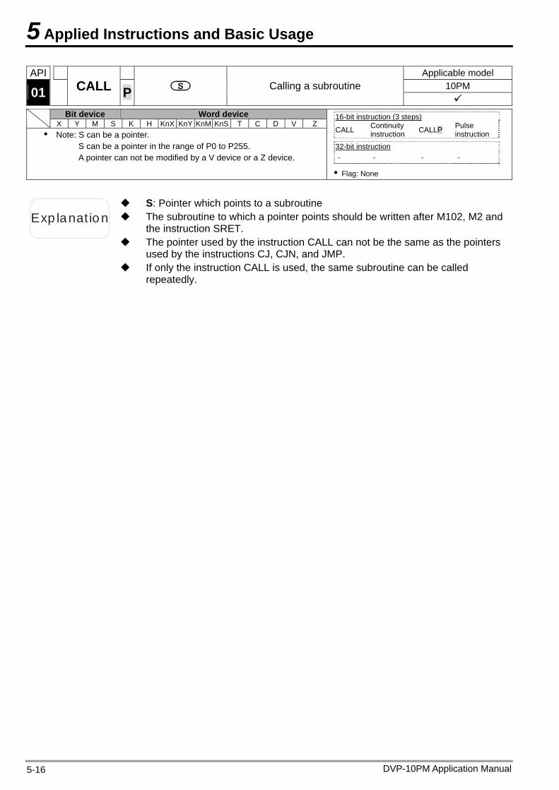
5 Applied Instructions and Basic Usage
API Applicable model 10PM 01 CALL P Calling a subroutine
Bit device Word device X Y M S K H KnX KnY KnM KnS T C D V Z
Note: S can be a pointer. S can be a pointer in the range of P0 to P255. A pointer can not be modified by a V device or a Z device.
16-bit instruction (3 steps) CALL Continuity
instruction CALLP Pulse instruction
32-bit instruction - - - -
Flag: None
Exp lanat ion The subroutine to which a pointer points should be written after M102, M2 and the instruction SRET.
S: Pointer which points to a subroutine
The pointer used by the instruction CALL can not be the same as the pointers used by the instructions CJ, CJN, and JMP.
If only the instruction CALL is used, the same subroutine can be called repeatedly.
DVP-10PM Application Manual 5-16
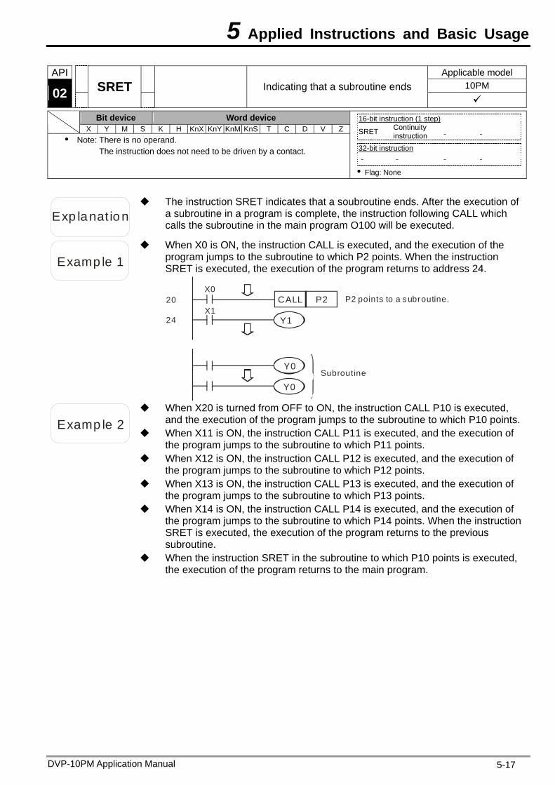
5 Applied Instructions and Basic Usage
API Applicable model 10PM 02
SRET
Indicating that a subroutine ends
Bit device Word device X Y M S K H KnX KnY KnM KnS T C D V Z
Note: There is no operand. The instruction does not need to be driven by a contact.
16-bit instruction (1 step) SRET Continuity
instruction - -
32-bit instruction - - - -
Flag: None
Exp lanat ion
The instruction SRET indicates that a soubroutine ends. After the execution of a subroutine in a program is complete, the instruction following CALL which calls the subroutine in the main program O100 will be executed.
Examp le 1
When X0 is ON, the instruction CALL is executed, and the execution of the program jumps to the subroutine to which P2 points. When the instruction SRET is executed, the execution of the program returns to address 24.
X0
X1CALL P2
Y1
20 P2 points to a subroutine.
24
SubroutineY0
Y0
Examp le 2
When X20 is turned from OFF to ON, the instruction CALL P10 is executed, and the execution of the program jumps to the subroutine to which P10 points.
When X11 is ON, the instruction CALL P11 is executed, and the execution of the program jumps to the subroutine to which P11 points.
When X12 is ON, the instruction CALL P12 is executed, and the execution of the program jumps to the subroutine to which P12 points.
When X13 is ON, the instruction CALL P13 is executed, and the execution of the program jumps to the subroutine to which P13 points.
When X14 is ON, the instruction CALL P14 is executed, and the execution of the program jumps to the subroutine to which P14 points. When the instruction SRET is executed, the execution of the program returns to the previous subroutine.
When the instruction SRET in the subroutine to which P10 points is executed, the execution of the program returns to the main program.
DVP-10PM Application Manual 5-17
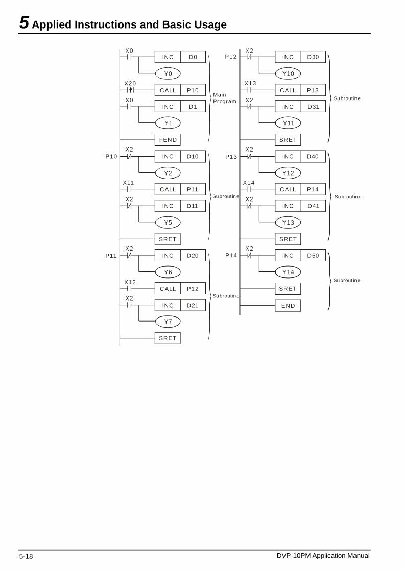
5 Applied Instructions and Basic Usage
Su brout in e
Main Program
Su brout in e
Su brout in e
Su brout in e
Su brout in e
X0
X20
INC D0
Y0
CALL P10X0
INC D1
Y1
FEND
INC D10X2
P10
Y2
X2
X11CALL P11
INC D11
Y5
SRET
INC D20X2
P11
Y6
X12CALL P12
X2INC D21
Y7
SRET
X2
X13
X2
X2
X2
X14
X2
P13
P14
P12 INC D30
Y10
CALL P13
INC D31
Y11
SRET
INC D40
Y12
CALL P14
INC D41
Y13
SRET
INC D50
Y14
SRET
END
DVP-10PM Application Manual 5-18
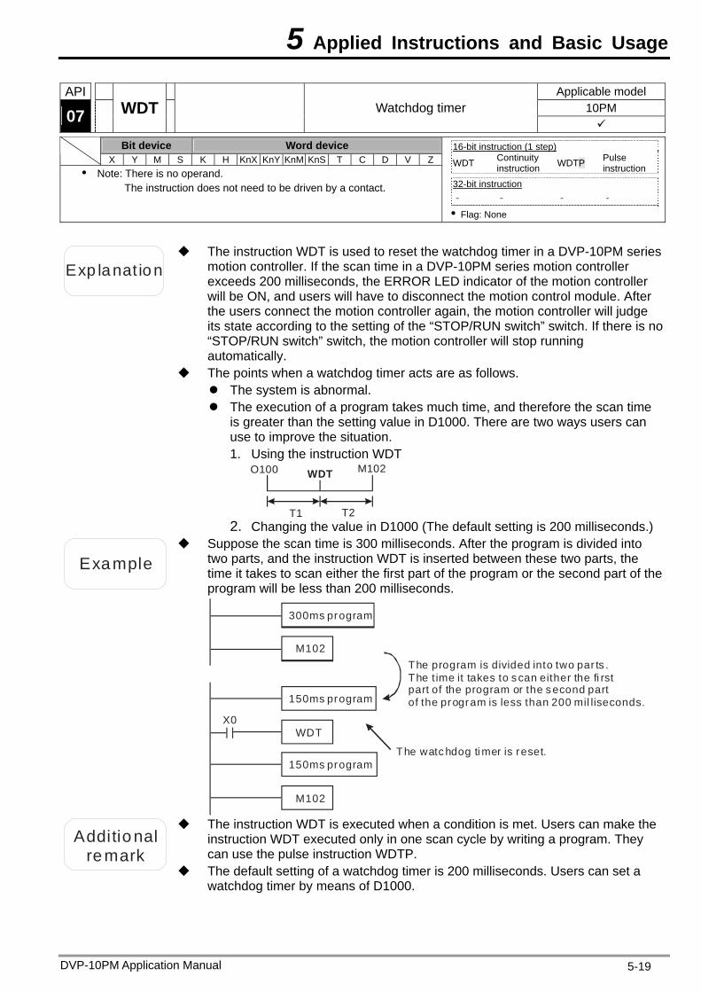
5 Applied Instructions and Basic Usage
DVP-10PM Application Manual 5-19
API Applicable model 10PM 07 WDT Watchdog timer
Bit device Word device X Y M S K H KnX KnY KnM KnS T C D V Z
Note: There is no operand. The instruction does not need to be driven by a contact.
16-bit instruction (1 step) WDT Continuity
instruction WDTP Pulse instruction
32-bit instruction - - - -
Flag: None
Exp lanat ion
The instruction WDT is used to reset the watchdog timer in a DVP-10PM series motion controller. If the scan time in a DVP-10PM series motion controller exceeds 200 milliseconds, the ERROR LED indicator of the motion controller will be ON, and users will have to disconnect the motion control module. After the users connect the motion controller again, the motion controller will judge its state according to the setting of the “STOP/RUN switch” switch. If there is no “STOP/RUN switch” switch, the motion controller will stop running automatically.
The points when a watchdog timer acts are as follows. The system is abnormal. The execution of a program takes much time, and therefore the scan time
is greater than the setting value in D1000. There are two ways users can use to improve the situation. 1. Using the instruction WDT
T1 T2
O100 M102WDT
2. Changing the value in D1000 (The default setting is 200 milliseconds.)
Example
Suppose the scan time is 300 milliseconds. After the program is divided into two parts, and the instruction WDT is inserted between these two parts, the time it takes to scan either the first part of the program or the second part of the program will be less than 200 milliseconds.
X0
300ms program
M102
M102
150ms program
150ms program
WDT
The program is divided into two par ts . The t ime it takes to scan either the fi rst part of the program or the second part of the program is less than 200 mil liseconds.
The watc hdog ti mer is reset.
Additional
remark
The instruction WDT is executed when a condition is met. Users can make the instruction WDT executed only in one scan cycle by writing a program. They can use the pulse instruction WDTP.
The default setting of a watchdog timer is 200 milliseconds. Users can set a watchdog timer by means of D1000.
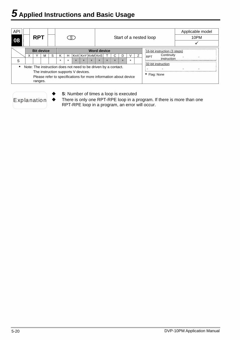
5 Applied Instructions and Basic Usage
API Applicable model 10PM 08 RPT S Start of a nested loop
Bit device Word device X Y M S K H KnX KnY KnM KnS T C D V Z
S * * * * * * * * * * Note: The instruction does not need to be driven by a contact.
The instruction supports V devices. Please refer to specifications for more information about device ranges.
16-bit instruction (3 steps) RPT Continuity
instruction - -
32-bit instruction - - - -
Flag: None
Exp lanat ion There is only one RPT-RPE loop in a program. If there is more than one RPT-RPE loop in a program, an error will occur.
S: Number of times a loop is executed
DVP-10PM Application Manual 5-20

5 Applied Instructions and Basic Usage
API Applicable model 10PM 09 RPE End of a nested loop
Bit device Word device X Y M S K H KnX KnY KnM KnS T C D V Z
Note: There is no operand. The instruction does not need to be driven by a contact.
16-bit instruction (1 step) RPE Continuity
instruction - -
32-bit instruction - - - -
Flag: None
Exp lanat ion
RPT in a program specifies that the RPT-RPE loop in the program must be executed N times.
N is in the range of K1 to K32,767. If N K1≦ , N will be regarded as K1. Users can skip the execution of the RPT-RPE loop in a program by means of
the instruction CJ. An error will occur if
1. the instruction RPE is before the instruction RPT. 2. there is RPT, but there is no RPE. 3. the number of times RPT is used is not the same as the number of times
RPE is used. There is only one RPT-RPE loop in a program. If there is more than one
RPT-RPE loop in a program, an error will occur.
Examp le 1
Part A can be executed three times by means of a RPT-RPE loop.
RPT K3
RPE
A
Examp le 2
When X0.7 is OFF, the program between RPT and RPE is executed. When X0.7 is ON, the instruction CJ is executed, the subroutine to which P6 points is executed, and the program between RPT and RPE is skipped.
X7
M0
M0
P6
MOV
RPT
MOV D0
D0
K3
K0
INC
RPE
D0
D1
CJ P6
Y10X10
DVP-10PM Application Manual 5-21
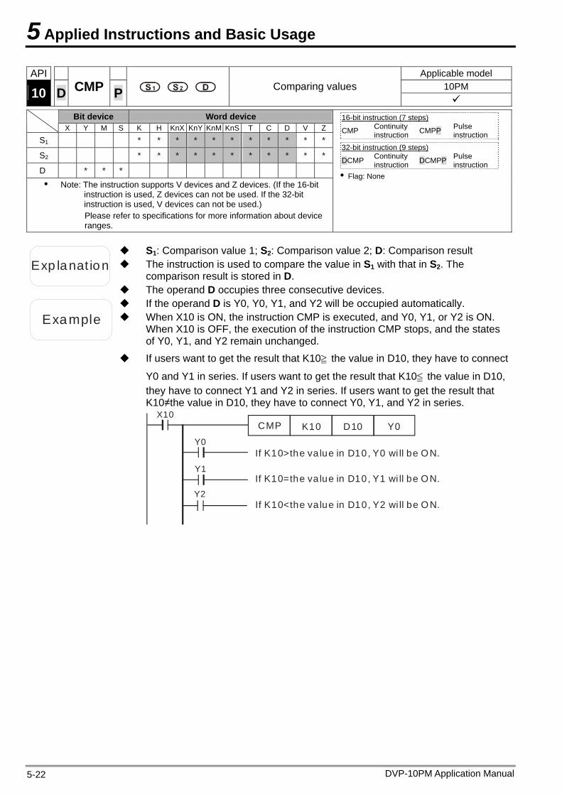
5 Applied Instructions and Basic Usage
DVP-10PM Application Manual 5-22
API Applicable model 10PM 10 D CMP P Comparing values
Bit device Word device X Y M S K H KnX KnY KnM KnS T C D V Z
S1 * * * * * * * * * * *
S2 * * * * * * * * * * *
D * * * Note: The instruction supports V devices and Z devices. (If the 16-bit
instruction is used, Z devices can not be used. If the 32-bit instruction is used, V devices can not be used.) Please refer to specifications for more information about device ranges.
16-bit instruction (7 steps) CMP Continuity
instruction CMPP Pulse instruction
32-bit instruction (9 steps)
DCMP Continuity instruction DCMPP Pulse
instruction Flag: None
Exp lanat ion The instruction is used to compare the value in S1 with that in S2. The comparison result is stored in D.
S1: Comparison value 1; S2: Comparison value 2; D: Comparison result
The operand D occupies three consecutive devices.
Example When X10 is ON, the instruction CMP is executed, and Y0, Y1, or Y2 is ON. When X10 is OFF, the execution of the instruction CMP stops, and the states of Y0, Y1, and Y2 remain unchanged.
If the operand D is Y0, Y0, Y1, and Y2 will be occupied automatically.
If users want to get the result that K10≧ the value in D10, they have to connect
Y0 and Y1 in series. If users want to get the result that K10≦ the value in D10, they have to connect Y1 and Y2 in series. If users want to get the result that K10≠the value in D10, they have to connect Y0, Y1, and Y2 in series.
X10CMP K10 D10 Y0
Y0
Y1
Y2
If K10>the va lue in D10, Y0 wi ll be ON.
If K10=the va lue in D10, Y1 wi ll be ON.
If K10<the va lue in D10, Y2 wi ll be O N.
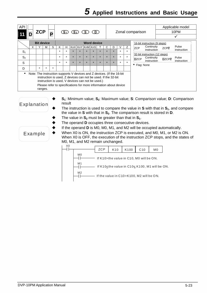
5 Applied Instructions and Basic Usage
DVP-10PM Application Manual 5-23
API Applicable model 10PM 11 D ZCP P Zonal comparison
Bit device Word device X Y M S K H KnX KnY KnM KnS T C D V Z
S1 * * * * * * * * * * *
S2 * * * * * * * * * * *
S * * * * * * * * * * *
D * * * Note: The instruction supports V devices and Z devices. (If the 16-bit
instruction is used, Z devices can not be used. If the 32-bit instruction is used, V devices can not be used.) Please refer to specifications for more information about device ranges.
16-bit instruction (9 steps) ZCP Continuity
instruction ZCPP Pulse instruction
32-bit instruction (12 steps)
DZCP Continuity instruction DZCPP Pulse
instruction Flag: None
Exp lanat ion
S1: Minimum value; S2: Maximum value; S: Comparison value; D: Comparison result
The instruction is used to compare the value in S with that in S1, and compare the value in S with that in S2. The comparison result is stored in D.
The value in S2 must be greater than that in S1. The operand D occupies three consecutive devices.
Example When X0 is ON, the instruction ZCP is executed, and M0, M1, or M2 is ON. When X0 is OFF, the execution of the instruction ZCP stops, and the states of M0, M1, and M2 remain unchanged.
If the operand D is M0, M0, M1, and M2 will be occupied automatically.
X0ZCP K10 K100 C10
M0
M1
M2
If K10 M0 wi ll be ON.>the va lue in C10,
If K10<the va lue in C10< K100, M1 wil l be ON.
If the va lue in C10 K100, M2 wi ll be O N. >
M0
= =
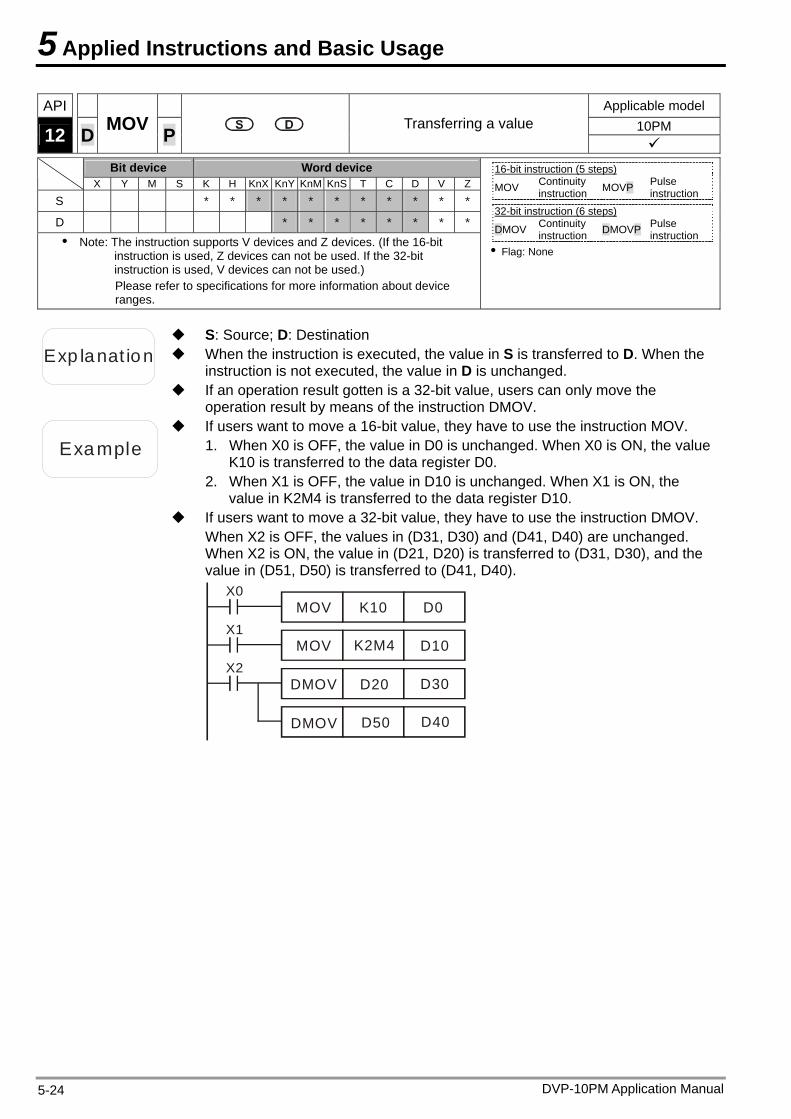
5 Applied Instructions and Basic Usage
DVP-10PM Application Manual 5-24
API Applicable model 10PM 12 D MOV P Transferring a value
Bit device Word device X Y M S K H KnX KnY KnM KnS T C D V Z
S * * * * * * * * * * *
D * * * * * * * *
Note: The instruction supports V devices and Z devices. (If the 16-bit instruction is used, Z devices can not be used. If the 32-bit instruction is used, V devices can not be used.) Please refer to specifications for more information about device ranges.
16-bit instruction (5 steps) MOV Continuity
instruction MOVP Pulse instruction
32-bit instruction (6 steps)
DMOV Continuity instruction DMOVP Pulse
instruction Flag: None
Exp lanat ion When the instruction is executed, the value in S is transferred to D. When the instruction is not executed, the value in D is unchanged.
S: Source; D: Destination
If an operation result gotten is a 32-bit value, users can only move the operation result by means of the instruction DMOV.
Example
If users want to move a 16-bit value, they have to use the instruction MOV. 1. When X0 is OFF, the value in D0 is unchanged. When X0 is ON, the value
K10 is transferred to the data register D0. 2. When X1 is OFF, the value in D10 is unchanged. When X1 is ON, the
value in K2M4 is transferred to the data register D10. If users want to move a 32-bit value, they have to use the instruction DMOV.
When X2 is OFF, the values in (D31, D30) and (D41, D40) are unchanged. When X2 is ON, the value in (D21, D20) is transferred to (D31, D30), and the value in (D51, D50) is transferred to (D41, D40).
X0MOV K10 D0
X1MOV K2M4 D10
X2DMOV D20 D30
DMOV D50 D40
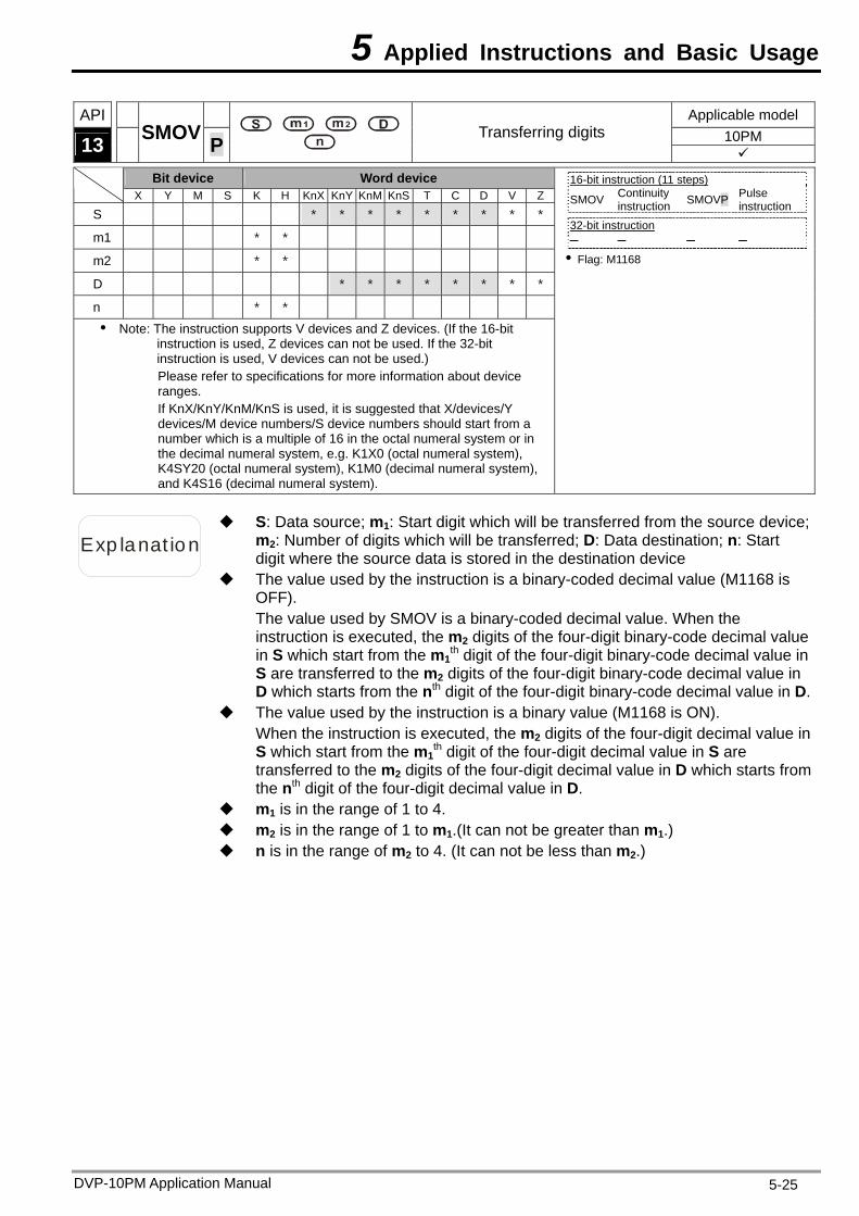
5 Applied Instructions and Basic Usage
DVP-10PM Application Manual 5-25
API Applicable model 10PM 13 SMOV P
Transferring digits
Bit device Word device X Y M S K H KnX KnY KnM KnS T C D V Z
S * * * * * * * * *
m1 * * m2 * * D * * * * * * * *
n * * Note: The instruction supports V devices and Z devices. (If the 16-bit
instruction is used, Z devices can not be used. If the 32-bit instruction is used, V devices can not be used.) Please refer to specifications for more information about device ranges. If KnX/KnY/KnM/KnS is used, it is suggested that X/devices/Y devices/M device numbers/S device numbers should start from a number which is a multiple of 16 in the octal numeral system or in the decimal numeral system, e.g. K1X0 (octal numeral system), K4SY20 (octal numeral system), K1M0 (decimal numeral system), and K4S16 (decimal numeral system).
16-bit instruction (11 steps) SMOV Continuity
instruction SMOVP Pulse instruction
32-bit instruction Flag: M1168
Exp lanat ion
S: Data source; m1: Start digit which will be transferred from the source device; m2: Number of digits which will be transferred; D: Data destination; n: Start digit where the source data is stored in the destination device
The value used by the instruction is a binary-coded decimal value (M1168 is OFF). The value used by SMOV is a binary-coded decimal value. When the instruction is executed, the m2 digits of the four-digit binary-code decimal value in S which start from the m1
th digit of the four-digit binary-code decimal value in S are transferred to the m2 digits of the four-digit binary-code decimal value in D which starts from the nth digit of the four-digit binary-code decimal value in D.
The value used by the instruction is a binary value (M1168 is ON). When the instruction is executed, the m2 digits of the four-digit decimal value in S which start from the m1
th digit of the four-digit decimal value in S are transferred to the m2 digits of the four-digit decimal value in D which starts from the nth digit of the four-digit decimal value in D.
m1 is in the range of 1 to 4. m2 is in the range of 1 to m1.(It can not be greater than m1.) n is in the range of m2 to 4. (It can not be less than m2.)
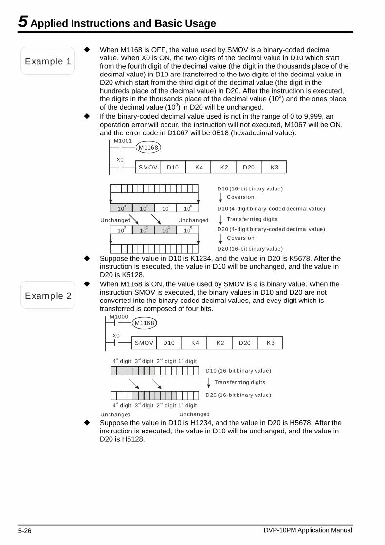
5 Applied Instructions and Basic Usage
Examp le 1
When M1168 is OFF, the value used by SMOV is a binary-coded decimal value. When X0 is ON, the two digits of the decimal value in D10 which start from the fourth digit of the decimal value (the digit in the thousands place of the decimal value) in D10 are transferred to the two digits of the decimal value in D20 which start from the third digit of the decimal value (the digit in the hundreds place of the decimal value) in D20. After the instruction is executed, the digits in the thousands place of the decimal value (103) and the ones place of the decimal value (100) in D20 will be unchanged.
If the binary-coded decimal value used is not in the range of 0 to 9,999, an operation error will occur, the instruction will not executed, M1067 will be ON, and the error code in D1067 will be 0E18 (hexadecimal value).
M1001M1168
X0SMOV D10 K4 K2 D20 K3
103
102
101
100
103
102
101
100
UnchangedUnchanged
Covers ion
Trans fer rri ng digits
Covers ion
D10 (16-bit binary value)
D10 (4-digit binary -coded deci mal val ue)
D20 ( )16-bit binary value
D20 ( )4-digit binary -coded deci mal val ue
Suppose the value in D10 is K1234, and the value in D20 is K5678. After the
instruction is executed, the value in D10 will be unchanged, and the value in D20 is K5128.
Examp le 2
When M1168 is ON, the value used by SMOV is a is binary value. When the instruction SMOV is executed, the binary values in D10 and D20 are not converted into the binary-coded decimal values, and evey digit which is transferred is composed of four bits.
UnchangedUnchanged
Trans fer rri ng digits
D10 ( )16-bit binary value
4 digitth 3 digitrd 2 digitnd 1 digitst
4 digitth 3 digitrd 2 digitnd 1 digitst
D20 ( )16-bit binary value
M1000M1168
X0SMOV D10 K4 K2 D20 K3
Suppose the value in D10 is H1234, and the value in D20 is H5678. After the
instruction is executed, the value in D10 will be unchanged, and the value in D20 is H5128.
DVP-10PM Application Manual 5-26
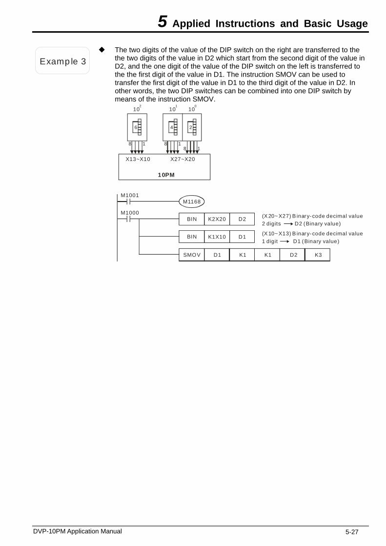
5 Applied Instructions and Basic Usage
Examp le 3
The two digits of the value of the DIP switch on the right are transferred to the the two digits of the value in D2 which start from the second digit of the value inD2, and the one digit of the value of the DIP switch on the left is transferred to the the first digit of the value in D1. The instruction SMOV can be used to transfer the first digit of the value in D1 to the third digit of the value in D2. In other words, the two DIP switches can be combined into one DIP switch by means of the instruction SMOV.
X13~X10 X27~X20
10PM
6 4 2
8 1 8 18 1
102
101
100
M1000BIN K2X20 D2
BIN K1X10 D1
SMOV D1 K1 K1 D2 K3
(X 20~ X27) B inary-code decimal value2 digits D2 (Binary value)
(X 10~ X13) B inary-code decimal value1 digit D1 ( )Binary value
M1001M1168
DVP-10PM Application Manual 5-27
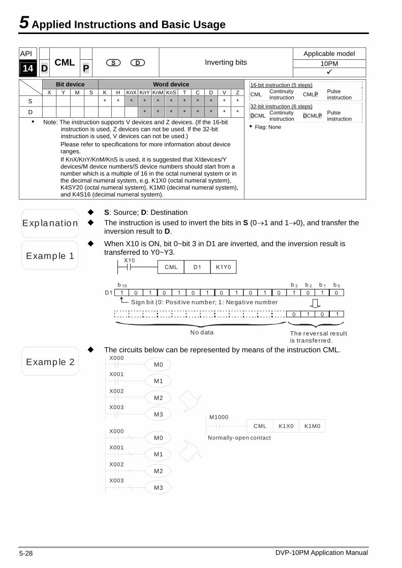
5 Applied Instructions and Basic Usage
DVP-10PM Application Manual 5-28
API Applicable model 10PM 14 D CML P Inverting bits
Bit device Word device X Y M S K H KnX KnY KnM KnS T C D V Z
S * * * * * * * * * * *
D * * * * * * * *
Note: The instruction supports V devices and Z devices. (If the 16-bit instruction is used, Z devices can not be used. If the 32-bit instruction is used, V devices can not be used.) Please refer to specifications for more information about device ranges. If KnX/KnY/KnM/KnS is used, it is suggested that X/devices/Y devices/M device numbers/S device numbers should start from a number which is a multiple of 16 in the octal numeral system or in the decimal numeral system, e.g. K1X0 (octal numeral system), K4SY20 (octal numeral system), K1M0 (decimal numeral system), and K4S16 (decimal numeral system).
16-bit instruction (5 steps) CML Continuity
instruction CMLP Pulse instruction
32-bit instruction (6 steps)
DCML Continuity instruction DCMLP Pulse
instruction Flag: None
Exp lanat ion The instruction is used to invert the bits in S (01 and 10), and transfer the inversion result to D.
S: Source; D: Destination
Examp le 1
When X10 is ON, bit 0~bit 3 in D1 are inverted, and the inversion result is transferred to Y0~Y3.
Sign b it (0 : Posit ive number; 1 : Negative number
X10CML D1 K1Y0
D1 1 0 1 0 1 0 1 0 1 0 1 0 1 0 1 0
0 1 0 1
b 0b 1b 2b 3b 15
No data The reversal resul t is transferred.
Examp le 2
The circuits below can be represented by means of the instruction CML. X000
M0
M1
M2
M3
X001
X002
X003
X000M0
M1
M2
M3
X001
X002
X003
M1000CML K1X0 K1M0
Normally-open contact
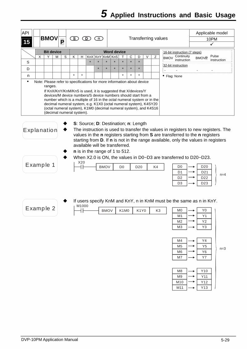
5 Applied Instructions and Basic Usage
DVP-10PM Application Manual 5-29
API Applicable model 10PM 15 BMOV P Transferring values
Bit device Word device X Y M S K H KnX KnY KnM KnS T C D V Z
S * * * * * * *
D * * * * * *
n * * * * * Note: Please refer to specifications for more information about device
ranges. If KnX/KnY/KnM/KnS is used, it is suggested that X/devices/Y devices/M device numbers/S device numbers should start from a number which is a multiple of 16 in the octal numeral system or in the decimal numeral system, e.g. K1X0 (octal numeral system), K4SY20 (octal numeral system), K1M0 (decimal numeral system), and K4S16 (decimal numeral system).
16-bit instruction (7 steps) BMOV Continuity
instruction BMOVP Pulse instruction
32-bit instruction - - - -
Flag: None
Exp lanat ion The instruction is used to transfer the values in registers to new registers. The values in the n registers starting from S are transferred to the n registers starting from D. If n is not in the range available, only the values in registers available will be transferred.
S: Source; D: Destination; n: Length
n is in the range of 1 to 512.
Examp le 1
When X2.0 is ON, the values in D0~D3 are transferred to D20~D23. X20
D20 K4 D0D1D2D3
D20D21D22D23
n=4
D0BMOV
Examp le 2
If users specify KnM and KnY, n in KnM must be the same as n in KnY. M1000
K1M0 K1Y0 K3 M0M1M2M3
M4M5M6M7
M8M9
M10
n=3
M11
Y0Y1Y2Y3
Y4Y5Y6Y7
Y10Y11Y12Y13
BMOV
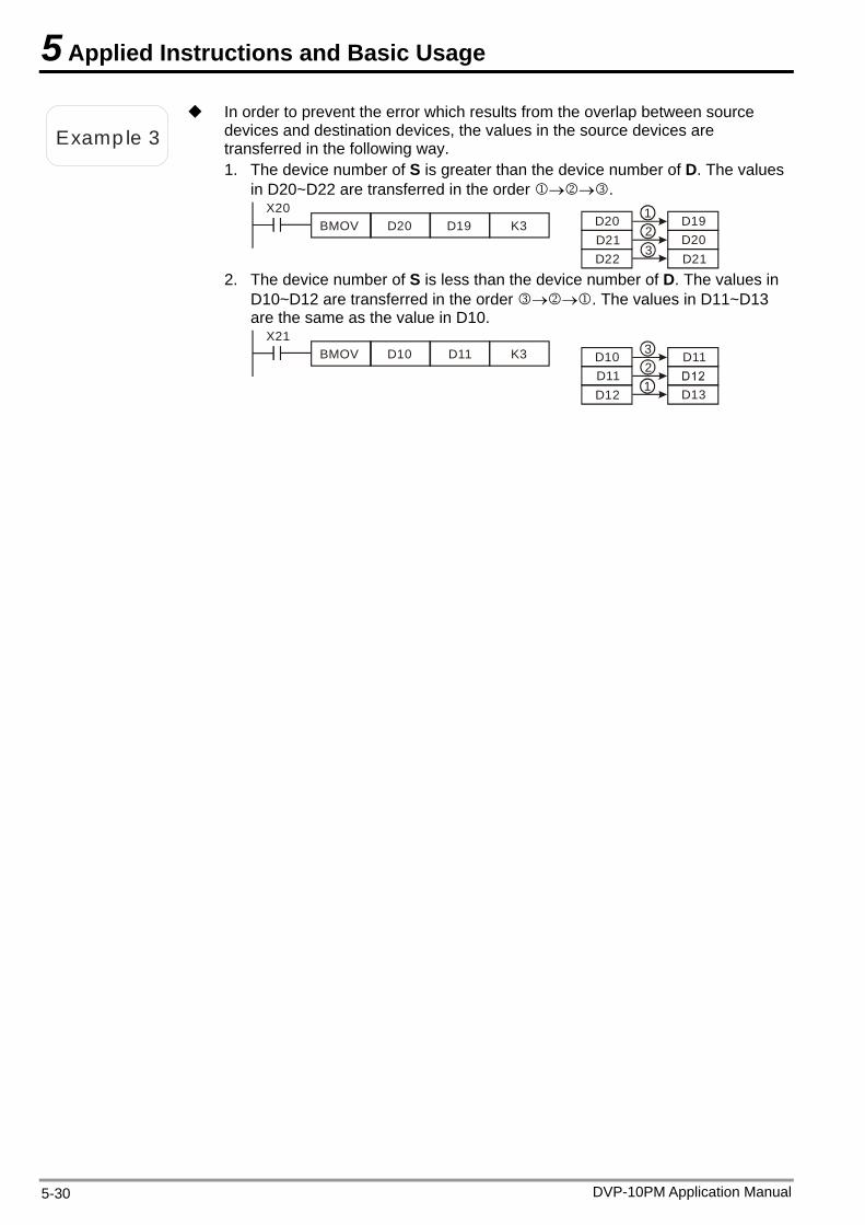
5 Applied Instructions and Basic Usage
Examp le 3
In order to prevent the error which results from the overlap between source devices and destination devices, the values in the source devices are transferred in the following way. 1. The device number of S is greater than the device number of D. The values
in D20~D22 are transferred in the order . X20
BMOV D20 D19 K3 D19D20D21
D20D21D22
21
3
2. The device number of S is less than the device number of D. The values in D10~D12 are transferred in the order . The values in D11~D13 are the same as the value in D10.
D11
D13
X21BMOV D10 D11 K3 D10
D11D12
1
32
DVP-10PM Application Manual 5-30
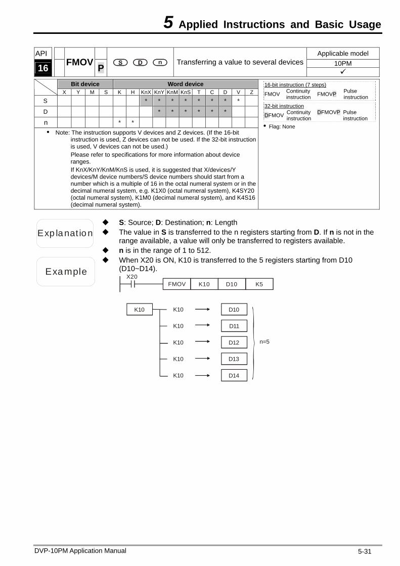
5 Applied Instructions and Basic Usage
DVP-10PM Application Manual 5-31
API Applicable model 10PM 16 FMOV P Transferring a value to several devices
Bit device Word device X Y M S K H KnX KnY KnM KnS T C D V Z
S * * * * * * * *
D * * * * * *
n * * Note: The instruction supports V devices and Z devices. (If the 16-bit
instruction is used, Z devices can not be used. If the 32-bit instruction is used, V devices can not be used.) Please refer to specifications for more information about device ranges. If KnX/KnY/KnM/KnS is used, it is suggested that X/devices/Y devices/M device numbers/S device numbers should start from a number which is a multiple of 16 in the octal numeral system or in the decimal numeral system, e.g. K1X0 (octal numeral system), K4SY20 (octal numeral system), K1M0 (decimal numeral system), and K4S16 (decimal numeral system).
16-bit instruction (7 steps) FMOV Continuity
instruction FMOVP Pulse instruction
32-bit instruction
DFMOV Continuity instruction
DFMOVP Pulse instruction
Flag: None
Exp lanat ion The value in S is transferred to the n registers starting from D. If n is not in the range available, a value will only be transferred to registers available.
S: Source; D: Destination; n: Length
n is in the range of 1 to 512.
Example
When X20 is ON, K10 is transferred to the 5 registers starting from D10 (D10~D14).
X20D10 K5FMOV K10
K10
K10
K10
K10
K10
K10 D10
D11
D12
D13
D14
n=5
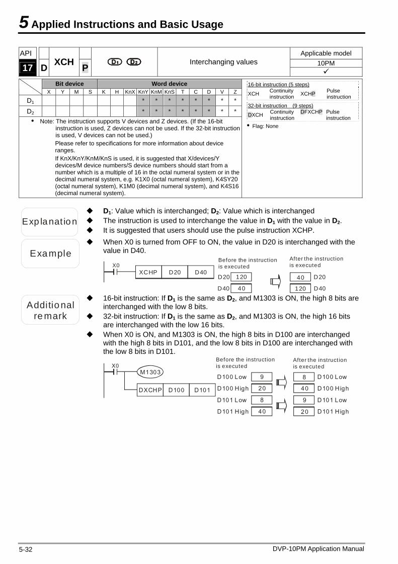
5 Applied Instructions and Basic Usage
DVP-10PM Application Manual 5-32
API Applicable model 10PM 17 D XCH P Interchanging values
Bit device Word device X Y M S K H KnX KnY KnM KnS T C D V Z
D1 * * * * * * * *
D2 * * * * * * * *
Note: The instruction supports V devices and Z devices. (If the 16-bit instruction is used, Z devices can not be used. If the 32-bit instruction is used, V devices can not be used.) Please refer to specifications for more information about device ranges. If KnX/KnY/KnM/KnS is used, it is suggested that X/devices/Y devices/M device numbers/S device numbers should start from a number which is a multiple of 16 in the octal numeral system or in the decimal numeral system, e.g. K1X0 (octal numeral system), K4SY20 (octal numeral system), K1M0 (decimal numeral system), and K4S16 (decimal numeral system).
16-bit instruction (5 steps) XCH Continuity
instruction XCHP Pulse instruction
32-bit instruction (9 steps)
DXCH Continuity instruction
DFXCHP Pulse instruction
Flag: None
Exp lanat ion The instruction is used to interchange the value in D1 with the value in D2.
D1: Value which is interchanged; D2: Value which is interchanged
It is suggested that users should use the pulse instruction XCHP.
Example
When X0 is turned from OFF to ON, the value in D20 is interchanged with the value in D40.
X0XCHP D20 D40
D40
D20 120
40
Before the instruction is executed
After the instruction is executed
40
120
D20
D40
Additional
remark 32-bit instruction: If D1 is the same as D2, and M1303 is ON, the high 16 bits are interchanged with the low 16 bits.
16-bit instruction: If D1 is the same as D2, and M1303 is ON, the high 8 bits are interchanged with the low 8 bits.
When X0 is ON, and M1303 is ON, the high 8 bits in D100 are interchanged with the high 8 bits in D101, and the low 8 bits in D100 are interchanged with the low 8 bits in D101.
Before the instruction is executed
After the instruction is executedX0
M13039
20
20
9
D100 Low
D100 High
8
40
40
8
D101 Low
D101 High
D100 Low
D100 High
D101 Low
D101 High
DXCHP D100 D101
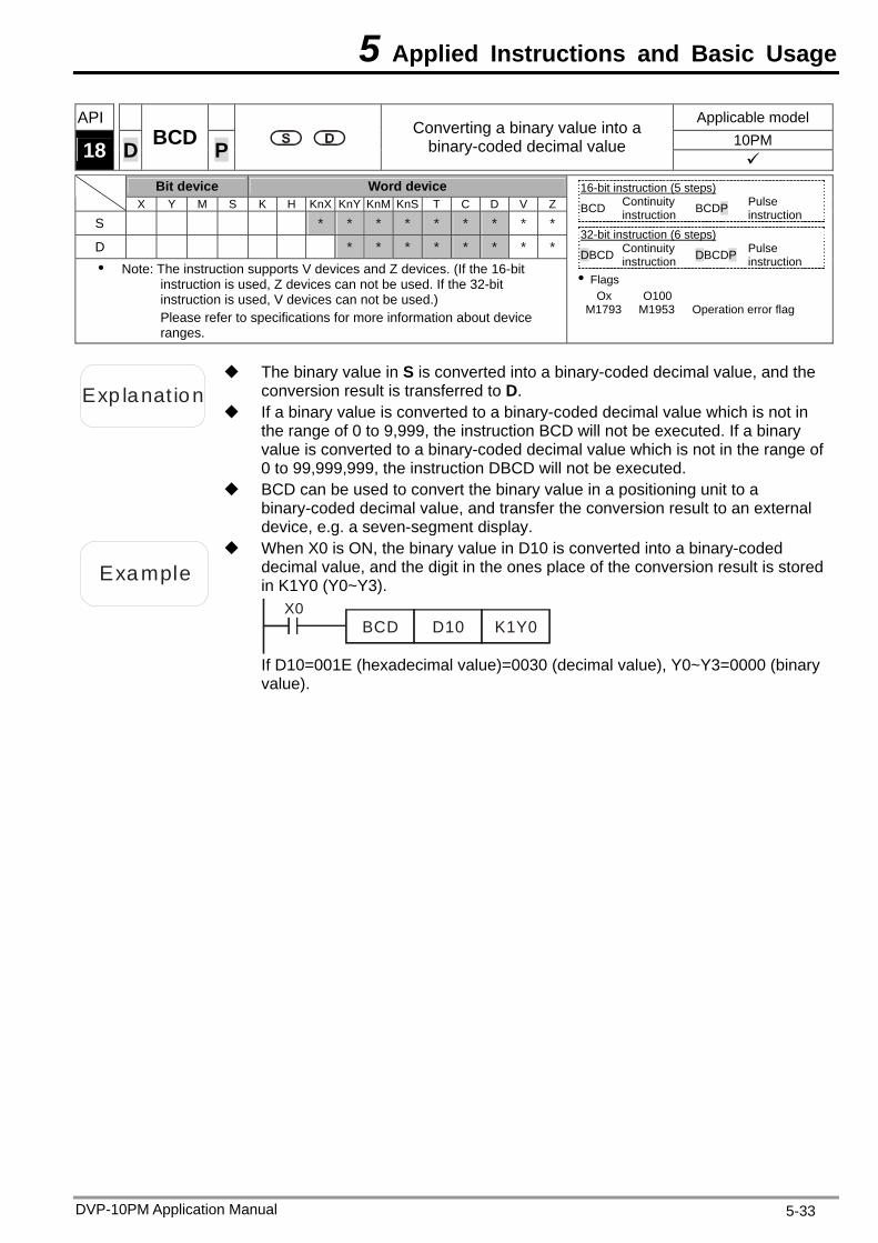
5 Applied Instructions and Basic Usage
DVP-10PM Application Manual 5-33
API Applicable model 10PM 18 D BCD P
Converting a binary value into a binary-coded decimal value
Bit device Word device
X Y M S K H KnX KnY KnM KnS T C D V Z
S * * * * * * * * *
D * * * * * * * *
Note: The instruction supports V devices and Z devices. (If the 16-bit instruction is used, Z devices can not be used. If the 32-bit instruction is used, V devices can not be used.) Please refer to specifications for more information about device ranges.
16-bit instruction (5 steps) BCD Continuity
instruction BCDP Pulse instruction
32-bit instruction (6 steps)
DBCD Continuity instruction DBCDP Pulse
instruction Flags
Ox O100 M 1793 M1953 Operation error flag
Exp lanat ion
The binary value in S is converted into a binary-coded decimal value, and the conversion result is transferred to D.
If a binary value is converted to a binary-coded decimal value which is not in the range of 0 to 9,999, the instruction BCD will not be executed. If a binary value is converted to a binary-coded decimal value which is not in the range of 0 to 99,999,999, the instruction DBCD will not be executed.
BCD can be used to convert the binary value in a positioning unit to a binary-coded decimal value, and transfer the conversion result to an external device, e.g. a seven-segment display.
Example
When X0 is ON, the binary value in D10 is converted into a binary-coded decimal value, and the digit in the ones place of the conversion result is stored in K1Y0 (Y0~Y3).
X0BCD D10 K1Y0
If D10=001E (hexadecimal value)=0030 (decimal value), Y0~Y3=0000 (binary value).
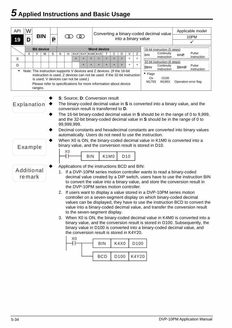
5 Applied Instructions and Basic Usage
DVP-10PM Application Manual 5-34
API W Applicable model 10PM 19 D BIN P
Converting a binary-coded decimal value into a binary value
Bit device Word device
X Y M S K H KnX KnY KnM KnS T C D V Z
S * * * * * * * * *
D * * * * * * * *
Note: The instruction supports V devices and Z devices. (If the 16-bit instruction is used, Z devices can not be used. If the 32-bit instruction is used, V devices can not be used.) Please refer to specifications for more information about device ranges.
16-bit instruction (5 steps) BIN Continuity
instruction BINP Pulse instruction
32-bit instruction (6 steps)
DBIN Continuity instruction DBINP Pulse
instruction Flags
Ox O100 M1793 M1953 Operation error flag
Exp lanat ion
S: Source; D: Conversion result The binary-coded decimal value in S is converted into a binary value, and the
conversion result is transferred to D. The 16-bit binary-coded decimal value in S should be in the range of 0 to 9,999,
and the 32-bit binary-coded decimal value in S should be in the range of 0 to 99,999,999.
Decimal constants and hexadecimal constants are converted into binary values automatically. Users do not need to use the instruction.
Example
When X0 is ON, the binary-coded decimal value in K1M0 is converted into a binary value, and the conversion result is stored in D10.
X0BIN D10K1M0
Additional 1.remark
Applications of the instructions BCD and BIN: If a DVP-10PM series motion controller wants to read a binary-coded
decimal value created by a DIP switch, users have to use the instruction BIN to convert the value into a binary value, and store the conversion result in the DVP-10PM series motion controller.
2. If users want to display a value stored in a DVP-10PM series motion controller on a seven-segment display on which binary-coded decimal values can be displayed, they have to use the instruction BCD to convert the value into a binary-coded decimal value, and transfer the conversion result to the seven-segment display.
3. When X0 is ON, the binary-coded decimal value in K4M0 is converted into a binary value, and the conversion result is stored in D100. Subsequently, the binary value in D100 is converted into a binary-coded decimal value, and the conversion result is stored in K4Y20.
X0BIN D100K4X0
BCD D100 K4Y20
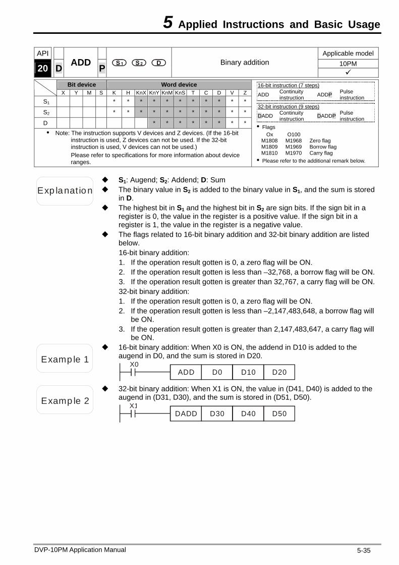
5 Applied Instructions and Basic Usage
DVP-10PM Application Manual 5-35
API Applicable model10PM 20 D ADD P Binary addition
Bit device Word device X Y M S K H KnX KnY KnM KnS T C D V Z
S1 * * * * * * * * * * *
S2 * * * * * * * * * * *
D * * * * * * * *
Note: The instruction supports V devices and Z devices. (If the 16-bit instruction is used, Z devices can not be used. If the 32-bit instruction is used, V devices can not be used.) Please refer to specifications for more information about device ranges.
16-bit instruction (7 steps) ADD Continuity
instruction ADDP Pulse instruction
32-bit instruction (9 steps)
DADD Continuity instruction DADDP Pulse
instruction Flags
Ox O100 M1808 M1968 Zero flag M1809 M1969 Borrow flag M1810 M1970 Carry flag Please refer to the additional remark below.
Exp lanat ion The binary value in S2 is added to the binary value in S1, and the sum is stored in D.
S1: Augend; S2: Addend; D: Sum
The highest bit in S1 and the highest bit in S2 are sign bits. If the sign bit in a register is 0, the value in the register is a positive value. If the sign bit in a register is 1, the value in the register is a negative value.
The flags related to 16-bit binary addition and 32-bit binary addition are listed below. 16-bit binary addition: 1. If the operation result gotten is 0, a zero flag will be ON. 2. If the operation result gotten is less than –32,768, a borrow flag will be ON.3. If the operation result gotten is greater than 32,767, a carry flag will be ON.32-bit binary addition: 1. If the operation result gotten is 0, a zero flag will be ON. 2. If the operation result gotten is less than –2,147,483,648, a borrow flag will
be ON. 3. If the operation result gotten is greater than 2,147,483,647, a carry flag will
be ON.
Examp le 1
16-bit binary addition: When X0 is ON, the addend in D10 is added to the augend in D0, and the sum is stored in D20.
X0ADD D0 D10 D20
Examp le 2
32-bit binary addition: When X1 is ON, the value in (D41, D40) is added to the augend in (D31, D30), and the sum is stored in (D51, D50).
X1DADD D30 D40 D50
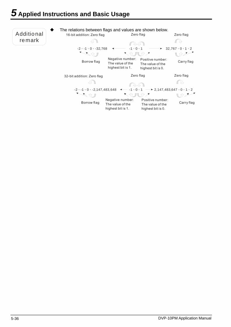
5 Applied Instructions and Basic Usage
Additional remark
The relations between flags and values are shown below. 16-bit addition: Zero flag Zero flag Zero flag
-2 -1 0 -32,768、 、 、 、 、-1 0 1 32,767 0 1 2、 、 、
Borrow flag Carry flag
Negative number:The value of the highest bit i s 1.
Positive number:The value of the highest bit i s 0.
Zero flag Zero flag
-2 -1 0 -2,147,483,648、 、 、 、 、-1 0 1 2,147,483,647 0 1 2、 、 、
Borrow flag Carry flag
32-bit addition: Zero flag
Negative number:The value of the highest bit i s 1.
Positive number:The value of the highest bit i s 0.
DVP-10PM Application Manual 5-36

5 Applied Instructions and Basic Usage
DVP-10PM Application Manual 5-37
API Applicable model 10PM 21 D SUB P Binary subtraction
Bit device Word device X Y M S K H KnX KnY KnM KnS T C D V Z
S1 * * * * * * * * * * *
S2 * * * * * * * * * * *
D * * * * * * * *
Note: The instruction supports V devices and Z devices. (If the 16-bit instruction is used, Z devices can not be used. If the 32-bit instruction is used, V devices can not be used.) Please refer to specifications for more information about device ranges.
16-bit instruction (7 steps) SUB Continuity
instruction SUBP Pulse instruction
32-bit instruction (9 steps)
DSUB Continuity instruction DSUBP Pulse
instruction Flags
Ox O100 M1808 M1968 Zero flag M1809 M1969 Borrow flag M1810 M1970 Carry flag Please refer to the additional remark below.
Exp lanat ion The binary value in S2 is subtracted from the binary value in S1, and the difference is stored in D.
S1: Minuend; S2: Subtrahend; D: Difference
The highest bit in S1 and the highest bit in S2 are sign bits. If the sign bit in a register is 0, the value in the register is a positive value. If the sign bit in a register is 1, the value in the register is a negative value.
The flags related to 16-bit binary subtraction and 32-bit binary subtraction are listed below. 16-bit binary subtraction: 1. If the operation result gotten is 0, a zero flag will be ON. 2. If the operation result gotten is less than –32,768, a borrow flag will be ON.3. If the operation result gotten is greater than 32,767, a carry flag will be ON.32-bit binary subtraction: 1. If the operation result gotten is 0, a zero flag will be ON. 2. If the operation result gotten is less than –2,147,483,648, a borrow flag will
be ON. 3. If the operation result gotten is greater than 2,147,483,647, a carry flag will
be ON. Please refer to the additional remark on the instruction ADD for more
information about the relations between flags and values.
Examp le 1
16-bit binary subtraction: When X0 is ON, the subtrahend in D10 is subtracted from the minuend in D0, and the difference is stored in D20.
X0SUB D0 D10 D20
Examp le 2
When X1 is ON, the subtrahend in (D41, D40) is subtracted from the minuend in (D31, D30), and the difference is stored in (D51, D50).
X1DSUB D30 D40 D50
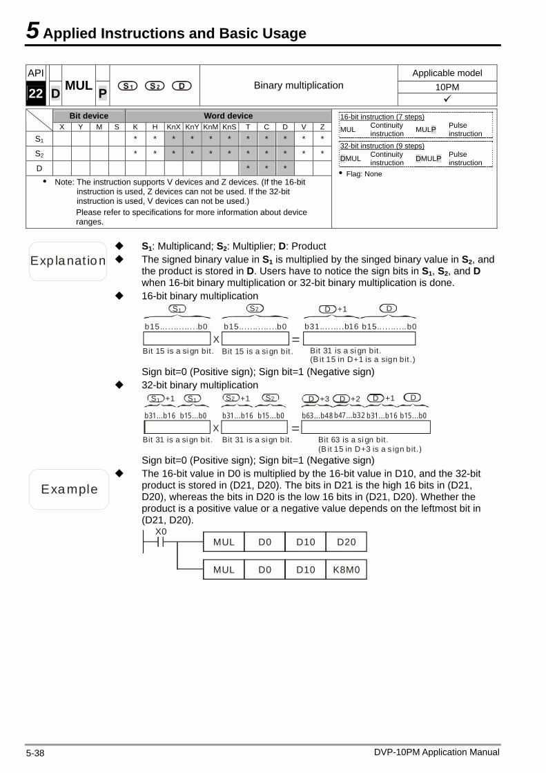
5 Applied Instructions and Basic Usage
DVP-10PM Application Manual 5-38
API Applicable model 10PM 22 D MUL P Binary multiplication
Bit device Word device X Y M S K H KnX KnY KnM KnS T C D V Z
S1 * * * * * * * * * * *
S2 * * * * * * * * * * *
D * * * Note: The instruction supports V devices and Z devices. (If the 16-bit
instruction is used, Z devices can not be used. If the 32-bit instruction is used, V devices can not be used.) Please refer to specifications for more information about device ranges.
16-bit instruction (7 steps) MUL Continuity
instruction MULP Pulse instruction
32-bit instruction (9 steps)
DMUL Continuity instruction DMULP Pulse
instruction Flag: None
Exp lanat ion The signed binary value in S1 is multiplied by the singed binary value in S2, and the product is stored in D. Users have to notice the sign bits in S1, S2, and D when 16-bit binary multiplication or 32-bit binary multiplication is done.
S1: Multiplicand; S2: Multiplier; D: Product
16-bit binary multiplication
b15....... .. .. .. .b0 b31.... . ... .b16
X =b15.... . .. . . .. . . .b0 b15.... ... . ...b0
Bit 15 is a si gn bit. Bit 15 is a si gn bit. Bit 31 is a si gn bit. (B it 15 in D+1 is a sign bit.)
S D1 2 DS +1
Sign bit=0 (Positive sign); Sign bit=1 (Negative sign)
32-bit binary multiplication
X =Bit 31 is a si gn bit. Bit 63 is a si gn bit.
(B it 15 in D+3 is a s ign bit.)Bit 31 is a si gn bit.
D +1 DDD2S2SS1 S1+1 +1 +2+3
b31...b16 b15...b0 b63...b48 b47...b32 b31...b16 b15...b0b31...b16 b15...b0
Sign bit=0 (Positive sign); Sign bit=1 (Negative sign)
Example
The 16-bit value in D0 is multiplied by the 16-bit value in D10, and the 32-bit product is stored in (D21, D20). The bits in D21 is the high 16 bits in (D21, D20), whereas the bits in D20 is the low 16 bits in (D21, D20). Whether the product is a positive value or a negative value depends on the leftmost bit in (D21, D20).
X0MUL D0 D10 D20
MUL D0 D10 K8M0
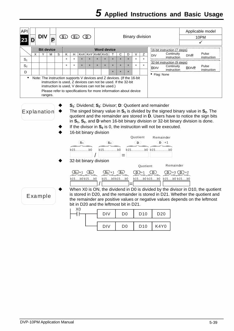
5 Applied Instructions and Basic Usage
DVP-10PM Application Manual 5-39
API Applicable model 10PM 23 D DIV P Binary division
Bit device Word device X Y M S K H KnX KnY KnM KnS T C D V Z
S1 * * * * * * * * * * *
S2 * * * * * * * * * * *
D * * * Note: The instruction supports V devices and Z devices. (If the 16-bit
instruction is used, Z devices can not be used. If the 32-bit instruction is used, V devices can not be used.) Please refer to specifications for more information about device ranges.
16-bit instruction (7 steps) DIV Continuity
instruction DIVP Pulse instruction
32-bit instruction (9 steps)
DDIV Continuity instruction DDIVP Pulse
instruction Flag: None
Exp lanat ion The singed binary value in S1 is divided by the signed binary value in S2. The quotient and the remainder are stored in D. Users have to notice the sign bits in S1, S2, and D when 16-bit binary division or 32-bit binary division is done.
S1: Dividend; S2: Divisor; D: Quotient and remainder
If the divisor in S2 is 0, the instruciton will not be executed. 16-bit binary division
b15....... . .. . . . .b0
S 1 S 2 DD +1
=/b15....... . .. . . . .b0 b15....... . .. . . . .b0 b15....... . .. . . . .b0
Quotient Remainder
32-bit binary division
Quotient Remainder
+1
/ =b15.....b0 b15.....b0 b15.....b0 b15.....b0 b15.....b0 b15.....b0 b15.....b0 b15.....b0
S 1 S 2S 1 S 2 +1 D D+1 D +3 D +2
Example
When X0 is ON, the dividend in D0 is divided by the divisor in D10, the quotient is stored in D20, and the remainder is stored in D21. Whether the quotient and the remainder are positive values or negative values depends on the leftmost bit in D20 and the leftmost bit in D21.
X0DIV D0 D10 D20
D0 D10 K4Y0DIV
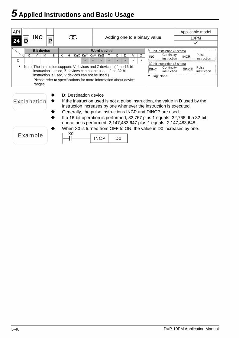
5 Applied Instructions and Basic Usage
DVP-10PM Application Manual 5-40
API Applicable model 10PM 24 D INC P Adding one to a binary value
Bit device Word device X Y M S K H KnX KnY KnM KnS T C D V Z
D * * * * * * * *
Note: The instruction supports V devices and Z devices. (If the 16-bit instruction is used, Z devices can not be used. If the 32-bit instruction is used, V devices can not be used.) Please refer to specifications for more information about device ranges.
16-bit instruction (3 steps) INC Continuity
instruction INCP Pulse instruction
32-bit instruction (3 steps)
DINC Continuity instruction DINCP Pulse
instruction Flag: None
Exp lanat ion If the instruction used is not a pulse instruction, the value in D used by the instruction increases by one whenever the instruction is executed.
D: Destination device
Generally, the pulse instructions INCP and DINCP are used. If a 16-bit operation is performed, 32,767 plus 1 equals -32,768. If a 32-bit
operation is performed, 2,147,483,647 plus 1 equals -2,147,483,648.
Example
When X0 is turned from OFF to ON, the value in D0 increases by one. X0
INCP D0
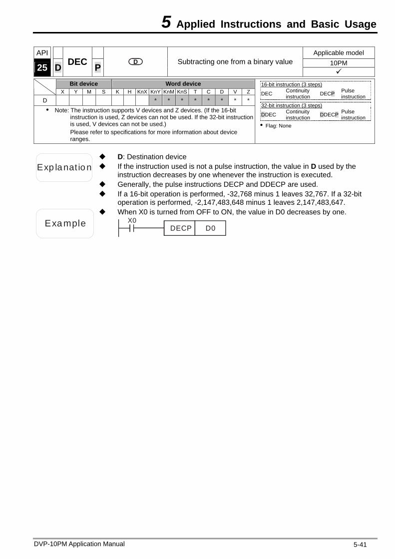
5 Applied Instructions and Basic Usage
DVP-10PM Application Manual 5-41
API Applicable model 10PM 25 D DEC P Subtracting one from a binary value
Bit device Word device X Y M S K H KnX KnY KnM KnS T C D V Z
D * * * * * * * *
Note: The instruction supports V devices and Z devices. (If the 16-bit instruction is used, Z devices can not be used. If the 32-bit instruction is used, V devices can not be used.) Please refer to specifications for more information about device ranges.
16-bit instruction (3 steps) DEC Continuity
instruction DECP Pulse instruction
32-bit instruction (3 steps)
DDEC Continuity instruction DDECP Pulse
instruction Flag: None
Exp lanat ion If the instruction used is not a pulse instruction, the value in D used by the instruction decreases by one whenever the instruction is executed.
D: Destination device
Generally, the pulse instructions DECP and DDECP are used. If a 16-bit operation is performed, -32,768 minus 1 leaves 32,767. If a 32-bit
operation is performed, -2,147,483,648 minus 1 leaves 2,147,483,647.
Example
When X0 is turned from OFF to ON, the value in D0 decreases by one. X0
DECP D0
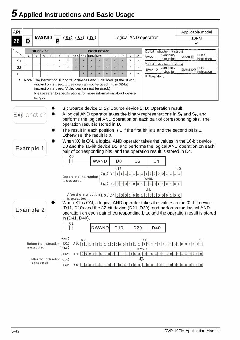
5 Applied Instructions and Basic Usage
DVP-10PM Application Manual 5-42
API Applicable model 10PM 26 D WAND P Logical AND operation
Bit device Word device X Y M S K H KnX KnY KnM KnS T C D V Z
S1 * * * * * * * * * * *
S2 * * * * * * * * * * *
D * * * * * * * *
Note: The instruction supports V devices and Z devices. (If the 16-bit instruction is used, Z devices can not be used. If the 32-bit instruction is used, V devices can not be used.) Please refer to specifications for more information about device ranges.
16-bit instruction (7 steps) WAND Continuity
instruction WANDP Pulse instruction
32-bit instruction (9 steps)
DWAND Continuity instruction DWANDP Pulse
instruction Flag: None
Exp lanat ion A logical AND operator takes the binary representations in S1 and S2, and performs the logical AND operation on each pair of corresponding bits. The operation result is stored in D.
S1: Source device 1; S2: Source device 2; D: Operation result
The result in each position is 1 if the first bit is 1 and the second bit is 1. Otherwise, the result is 0.
Examp le 1
When X0 is ON, a logical AND operator takes the values in the 16-bit device D0 and the 16-bit device D2, and performs the logical AND operation on each pair of corresponding bits, and the operation result is stored in D4.
X0WAND D0 D2 D4
0 0 0 0 1 1 1 11 1 1 1 1 1 1 1
0 0 0 0 0 0 0 0 0 0 01 1 1 1 1
0 0 0 0 0 0 0 0 0 0 0 0 01 1 1
WAND
b15 b0
Before the instruction is executed
S 1
S 2
D
D0
D2
D4After the instruction is executed
Examp le 2
When X1 is ON, a logical AND operator takes the values in the 32-bit device (D11, D10) and the 32-bit device (D21, D20), and performs the logical AND operation on each pair of corresponding bits, and the operation result is stored in (D41, D40).
X1DWAND D10 D20 D40
Before the instruction is executed
After the instruction is executed
DWAND
b15 b0b31S 1
S 2
D
D11 D10
D21 D20
D41 D40
1 1 1 1 1 1 1 1 0 0 0 0 1 1 1 1
0 0 0
0 0 0 0 0 0 0 0 0
1 1 1 1 1
111 0 0 0 0
0 00 00 000
1 1 1
11111
1111 11 1 1 11 1 1
0 0 0 0 0 0 0 0 0 0 0
0 00 00 00 00 00 00
0 00 0
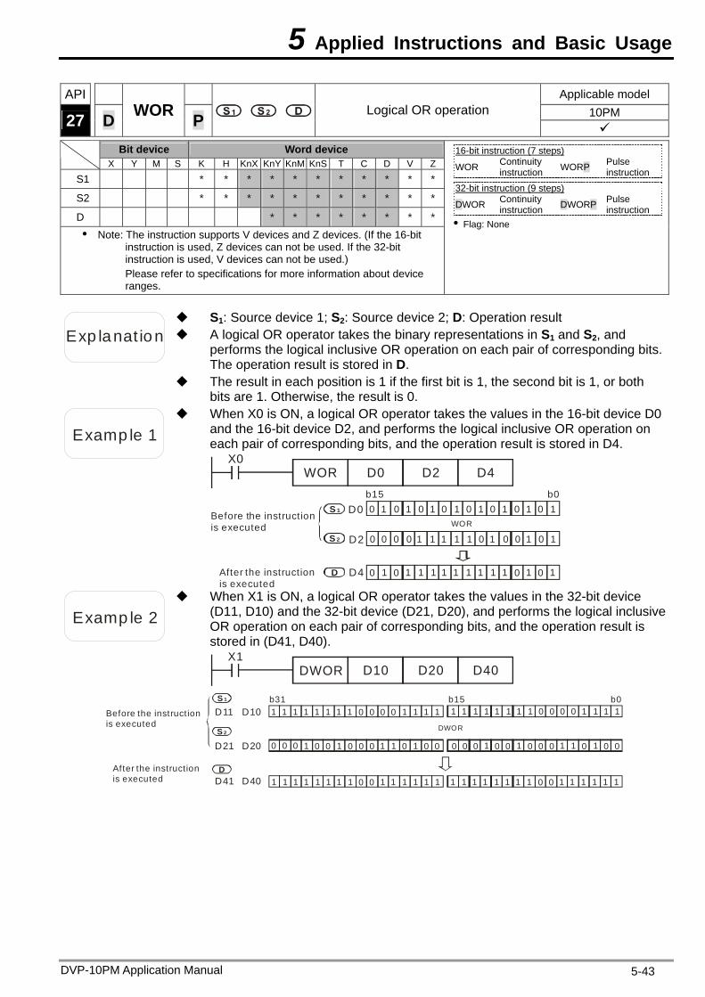
5 Applied Instructions and Basic Usage
DVP-10PM Application Manual 5-43
API Applicable model 10PM 27 D WOR P Logical OR operation
Bit device Word device X Y M S K H KnX KnY KnM KnS T C D V Z
S1 * * * * * * * * * * *
S2 * * * * * * * * * * *
D * * * * * * * *
Note: The instruction supports V devices and Z devices. (If the 16-bit instruction is used, Z devices can not be used. If the 32-bit instruction is used, V devices can not be used.) Please refer to specifications for more information about device ranges.
16-bit instruction (7 steps) WOR Continuity
instruction WORP Pulse instruction
32-bit instruction (9 steps)
DWOR Continuity instruction DWORP Pulse
instruction Flag: None
Exp lanat ion A logical OR operator takes the binary representations in S1 and S2, and performs the logical inclusive OR operation on each pair of corresponding bits. The operation result is stored in D.
S1: Source device 1; S2: Source device 2; D: Operation result
The result in each position is 1 if the first bit is 1, the second bit is 1, or both bits are 1. Otherwise, the result is 0.
Examp le 1
When X0 is ON, a logical OR operator takes the values in the 16-bit device D0 and the 16-bit device D2, and performs the logical inclusive OR operation on each pair of corresponding bits, and the operation result is stored in D4.
X0WOR D0 D2 D4
Before the instruction is executed
After the instruction is executed
0 11 1 1 1 1
0 0 0 0 0 0 01 1 1
0 0 0 01 1 1
WOR
b15 b0S 1
S 2
D
D0
D2
D4
0 00 0 0 0 0 1 1
0 1111 1
111 1 1 1 1 11
Examp le 2
When X1 is ON, a logical OR operator takes the values in the 32-bit device (D11, D10) and the 32-bit device (D21, D20), and performs the logical inclusiveOR operation on each pair of corresponding bits, and the operation result is stored in (D41, D40).
X1DWOR D10 D20 D40
Before the instruct ion is executed
After the instruction is executed
DWOR
b15 b0b31S 1
S 2
D
D11 D10
D21 D20
D41 D40
1 1 1 1 1 1 1 1 0 0 0 0 1 1 1 1
0 0 0
0 0
1 1 1 1 1
111
0 00 00 000 11111
1111 11 1 1 11 1 1
0 0 0 0 0 0 0 0 0 0 0
0 00 0
1 1 1 1 1 1 11 1 11 1111 1 1 1 1 1 11 1 110 0
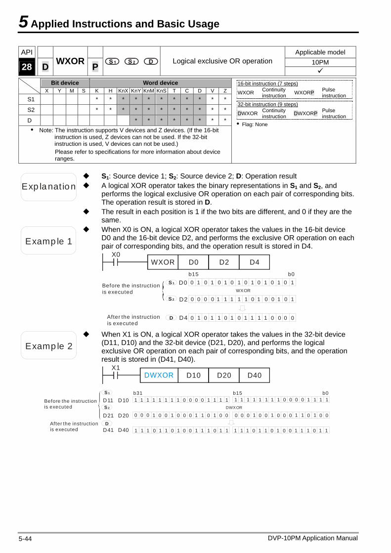
5 Applied Instructions and Basic Usage
DVP-10PM Application Manual 5-44
API Applicable model 10PM 28 D WXOR P Logical exclusive OR operation
Bit device Word device X Y M S K H KnX KnY KnM KnS T C D V Z
S1 * * * * * * * * * * *
S2 * * * * * * * * * * *
D * * * * * * * *
Note: The instruction supports V devices and Z devices. (If the 16-bit instruction is used, Z devices can not be used. If the 32-bit instruction is used, V devices can not be used.) Please refer to specifications for more information about device ranges.
16-bit instruction (7 steps) WXOR Continuity
instruction WXORP Pulse instruction
32-bit instruction (9 steps)
DWXOR Continuity instruction DWXORP Pulse
instruction Flag: None
Exp lanat ion A logical XOR operator takes the binary representations in S1 and S2, and performs the logical exclusive OR operation on each pair of corresponding bits. The operation result is stored in D.
S1: Source device 1; S2: Source device 2; D: Operation result
The result in each position is 1 if the two bits are different, and 0 if they are the same.
Examp le 1
When X0 is ON, a logical XOR operator takes the values in the 16-bit device D0 and the 16-bit device D2, and performs the exclusive OR operation on each pair of corresponding bits, and the operation result is stored in D4.
X0WXOR D0 D2 D4
Before the instruction is executed
After the instruction is executed
0 11 1 1 1 1
0 0 0 0 0 0 01 1 1
0 0 0 01 1
WXOR
b15 b0S 1
S 2
D
D0
D2
D4
0 00 0 0 0 0 1 1
0 1111 1
11 1 1 1 1 0 00 0
Examp le 2
When X1 is ON, a logical XOR operator takes the values in the 32-bit device (D11, D10) and the 32-bit device (D21, D20), and performs the logical exclusive OR operation on each pair of corresponding bits, and the operation result is stored in (D41, D40).
X1DWXOR D10 D20 D40
Before the instruction is executed
After the instruction is executed
DWXOR
b15 b0b31S 1
S 2
D
D11 D10
D21 D20
D41 D40
1 1 1 1 1 1 1 1 0 0 0 0 1 1 1 1
0 0 0
0 0
1 1 1 1 1 0 00 00 000 11111
1111 11 1 1 11 1 1
0 0 0 0 0 0 0 0 0 0 0
0 00 0
1 1 1 1 1 1 11 1 11 1 1 1 1 1 1 11 1 110 0 0000 0 0
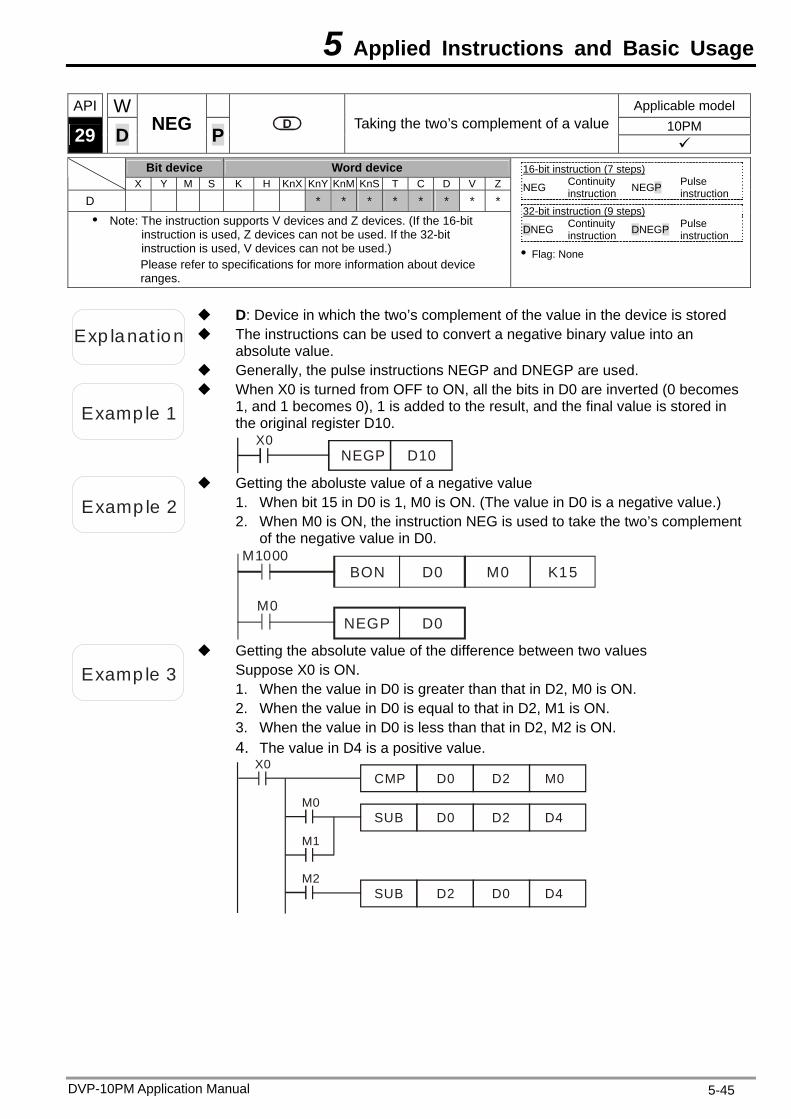
5 Applied Instructions and Basic Usage
DVP-10PM Application Manual 5-45
API W Applicable model 10PM 29 D NEG P Taking the two’s complement of a value
Bit device Word device X Y M S K H KnX KnY KnM KnS T C D V Z
D * * * * * * * *
Note: The instruction supports V devices and Z devices. (If the 16-bit instruction is used, Z devices can not be used. If the 32-bit instruction is used, V devices can not be used.) Please refer to specifications for more information about device ranges.
16-bit instruction (7 steps) NEG Continuity
instruction NEGP Pulse instruction
32-bit instruction (9 steps)
DNEG Continuity instruction DNEGP Pulse
instruction
Flag: None
Exp lanat ion The instructions can be used to convert a negative binary value into an absolute value.
D: Device in which the two’s complement of the value in the device is stored
Generally, the pulse instructions NEGP and DNEGP are used.
Examp le 1
When X0 is turned from OFF to ON, all the bits in D0 are inverted (0 becomes 1, and 1 becomes 0), 1 is added to the result, and the final value is stored in the original register D10.
X0NEGP D10
Examp le 2
Getting the aboluste value of a negative value 1. When bit 15 in D0 is 1, M0 is ON. (The value in D0 is a negative value.) 2. When M0 is ON, the instruction NEG is used to take the two’s complement
of the negative value in D0. M1000
BON D0 M0 K15
NEGP D0M0
Examp le 3
Getting the absolute value of the difference between two values Suppose X0 is ON. 1. When the value in D0 is greater than that in D2, M0 is ON. 2. When the value in D0 is equal to that in D2, M1 is ON. 3. When the value in D0 is less than that in D2, M2 is ON. 4. The value in D4 is a positive value.
X0
CMP D0 D2 M0
M0SUB D0 D2 D4
M2SUB D2 D0 D4
M1
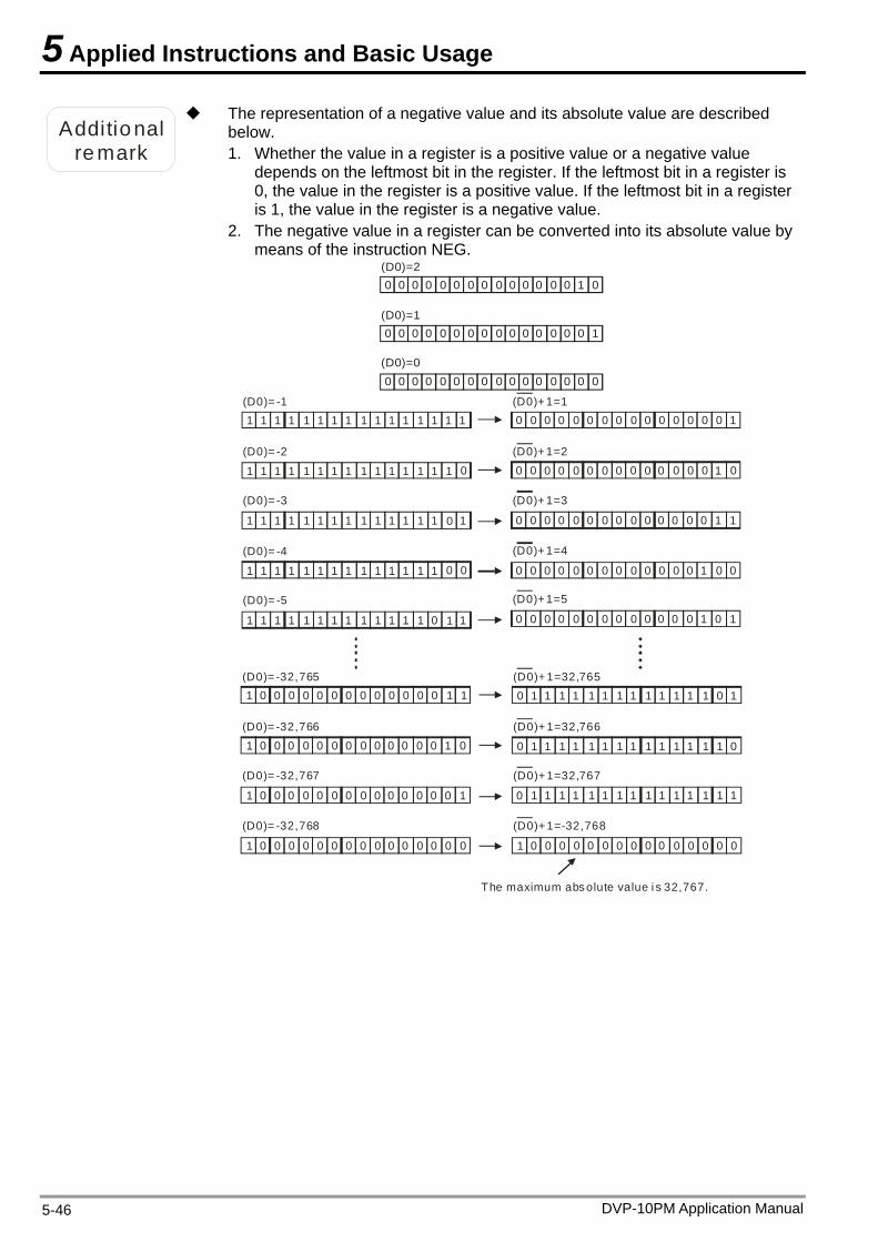
5 Applied Instructions and Basic Usage
DVP-10PM Application Manual 5-46
Additional
remark
The representation of a negative value and its absolute value are described below. 1. Whether the value in a register is a positive value or a negative value
depends on the leftmost bit in the register. If the leftmost bit in a register is 0, the value in the register is a positive value. If the leftmost bit in a register is 1, the value in the register is a negative value.
2. The negative value in a register can be converted into its absolute value by means of the instruction NEG.
0 0 0 0 0 0 0 0 0 0 0 0 0 0 01
0 0 0 0 0 0 0 0 0 0 0 0 0 0 10
0 0 0 0 0 0 0 0 0 0 0 0 0 0 00
(D0)=2
(D0)=1
(D0)=0
1 1 1
0
(D0)= -1
(D0)= -2
(D0)= -3
1 1 1 1 1 1 1 1 1 1 11 1
1 1
1
1 1 1 1 1 1 1 1 1 1 1 1 1
01 1 1 1 1 1 1 1 1 1 1 1 1 1
0(D0)= -4
(D0)= -5
1 1
1
1 1 1 1 1 1 1 1 1 1 1 1 0
11 1 1 1 1 1 1 1 1 1 1 1 1 0
1 0 0 0 0 0 0 0 0 0 0 0 0 0 11
1 0 0 0 0 0 0 0 0 0 0 0 0 0 01
1 0 0 0 0 0 0 0 0 0 0 0 0 0 10
(D0)= -32,765
(D0)= -32,766
(D0)= -32,767
1 0 0 0 0 0 0 0 0 0 0 0 0 0 00
(D0)= -32,768
0 1 1
(D0)+ 1=32,765
(D0)+ 1=32,766
(D0)+ 1=32,767
1 0 0 0 0 0 0 0 0 0 0 0 0 0 00
(D0)+ 1=-32,768
0 0 0 0 0 0 0 0 0 0 0 0 0 0 10
0 0 0 0 0 0 0 0 0 0 0 0 0 0 01
0 0 0 0 0 0 0 0 0 0 0 0 0 0 11
(D0)+ 1=1
(D0)+ 1=2
(D0)+ 1=3
0 0 0 0 0 0 0 0 0 0 0 0 0 1 00
(D0)+ 1=4
0 0 0 0 0 0 0 0 0 0 0 0 0 1 10
(D0)+ 1=5
1 1 1 1 1 1 1 1 1 1 1 1 1
0 1 01 1 1 1 1 1 1 1 1 1 1 1 1
0 1 11 1 1 1 1 1 1 1 1 1 1 1 0
The maximum absolute value i s 32,767.
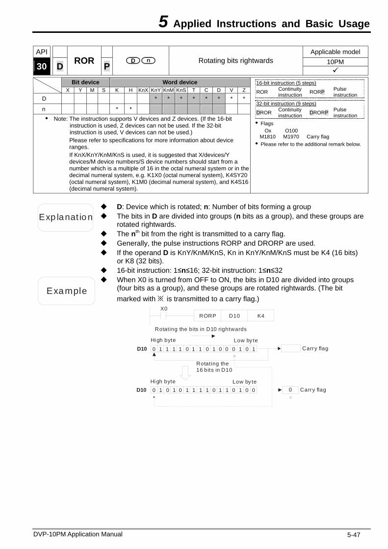
5 Applied Instructions and Basic Usage
API Applicable model 10PM 30 D ROR P Rotating bits rightwards
Bit device Word device X Y M S K H KnX KnY KnM KnS T C D V Z
D * * * * * * * *
n * * Note: The instruction supports V devices and Z devices. (If the 16-bit
instruction is used, Z devices can not be used. If the 32-bit instruction is used, V devices can not be used.) Please refer to specifications for more information about device ranges. If KnX/KnY/KnM/KnS is used, it is suggested that X/devices/Y devices/M device numbers/S device numbers should start from a number which is a multiple of 16 in the octal numeral system or in the decimal numeral system, e.g. K1X0 (octal numeral system), K4SY20 (octal numeral system), K1M0 (decimal numeral system), and K4S16 (decimal numeral system).
16-bit instruction (5 steps) ROR Continuity
instruction RORP Pulse instruction
32-bit instruction (9 steps)
DROR Continuity instruction DRORP Pulse
instruction Flags
Ox O100 M1810 M1970 Carry flag Please refer to the additional remark below.
Exp lanat ion The bits in D are divided into groups (n bits as a group), and these groups are rotated rightwards.
D: Device which is rotated; n: Number of bits forming a group
The nth bit from the right is transmitted to a carry flag. Generally, the pulse instructions RORP and DRORP are used. If the operand D is KnY/KnM/KnS, Kn in KnY/KnM/KnS must be K4 (16 bits)
or K8 (32 bits). 16-bit instruction: 1≤n≤16; 32-bit instruction: 1≤n≤32
Example
When X0 is turned from OFF to ON, the bits in D10 are divided into groups (four bits as a group), and these groups are rotated rightwards. (The bit marked with ※ is transmitted to a carry flag.)
0 1 1 1 0 1 0 1 0 0 11 1 0 0 1
0 1 0 1 1 1 0 0 111 1 00 1 0 0
Hi gh byte Low by te
*
X0RORP D10 K4
Rotating the bits in D10 rightwards
Rotating the 16 bits in D10
Carry flagD10
D10 Carry flag Low by te Hi gh byte
DVP-10PM Application Manual 5-47
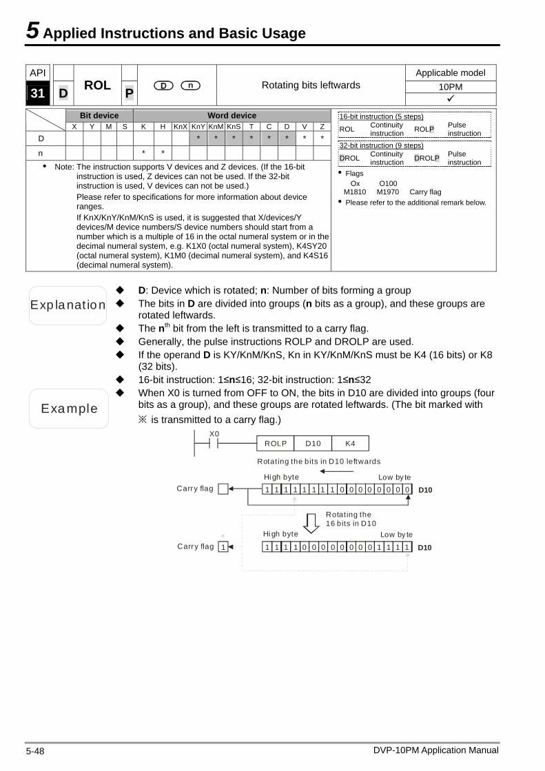
5 Applied Instructions and Basic Usage
DVP-10PM Application Manual 5-48
API Applicable model 10PM 31 D ROL P Rotating bits leftwards
Bit device Word device X Y M S K H KnX KnY KnM KnS T C D V Z
D * * * * * * * *
n * * Note: The instruction supports V devices and Z devices. (If the 16-bit
instruction is used, Z devices can not be used. If the 32-bit instruction is used, V devices can not be used.) Please refer to specifications for more information about device ranges. If KnX/KnY/KnM/KnS is used, it is suggested that X/devices/Y devices/M device numbers/S device numbers should start from a number which is a multiple of 16 in the octal numeral system or in the decimal numeral system, e.g. K1X0 (octal numeral system), K4SY20 (octal numeral system), K1M0 (decimal numeral system), and K4S16 (decimal numeral system).
16-bit instruction (5 steps) ROL Continuity
instruction ROLP Pulse instruction
32-bit instruction (9 steps)
DROL Continuity instruction DROLP Pulse
instruction Flags
Ox O100 M1810 M1970 Carry flag Please refer to the additional remark below.
Exp lanat ion The bits in D are divided into groups (n bits as a group), and these groups are rotated leftwards.
D: Device which is rotated; n: Number of bits forming a group
The nth bit from the left is transmitted to a carry flag. Generally, the pulse instructions ROLP and DROLP are used. If the operand D is KY/KnM/KnS, Kn in KY/KnM/KnS must be K4 (16 bits) or K8
(32 bits). 16-bit instruction: 1≤n≤16; 32-bit instruction: 1≤n≤32
Example
When X0 is turned from OFF to ON, the bits in D10 are divided into groups (four bits as a group), and these groups are rotated leftwards. (The bit marked with ※ is transmitted to a carry flag.)
Hi gh byte
Low by te
Rotating the bits in D10 leftwards
Rotating the 16 bits in D10
Carry flag
Carry flag Low by te
Hi gh byte
X0D10 K4
1 1 1 1 1 1 0 0 0 0 01 1 0 0 0
1 1 0 0 0 0 0 1 100 11 0 11 1
D10
D10
ROLP
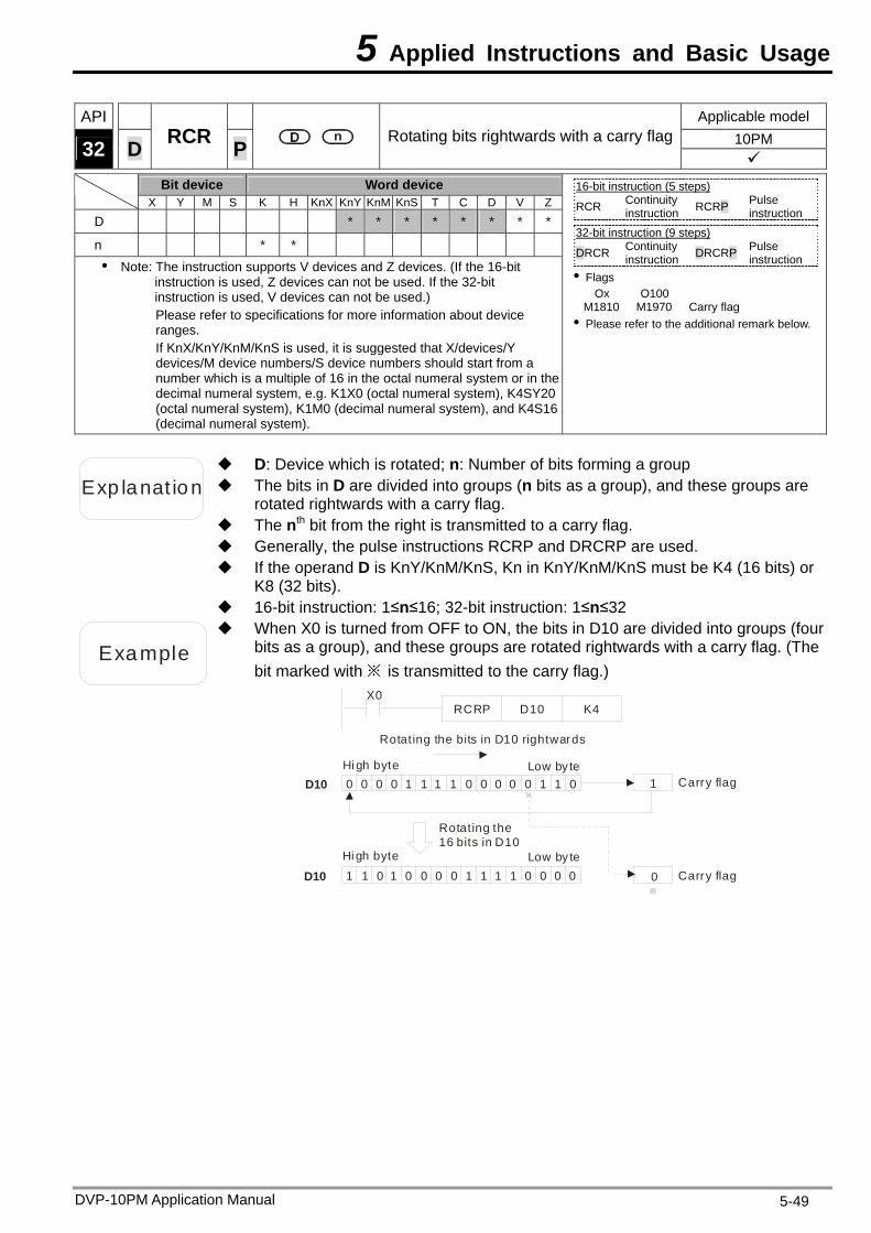
5 Applied Instructions and Basic Usage
DVP-10PM Application Manual 5-49
API Applicable model 10PM 32 D RCR P Rotating bits rightwards with a carry flag
Bit device Word device X Y M S K H KnX KnY KnM KnS T C D V Z
D * * * * * * * *
n * * Note: The instruction supports V devices and Z devices. (If the 16-bit
instruction is used, Z devices can not be used. If the 32-bit instruction is used, V devices can not be used.) Please refer to specifications for more information about device ranges. If KnX/KnY/KnM/KnS is used, it is suggested that X/devices/Y devices/M device numbers/S device numbers should start from a number which is a multiple of 16 in the octal numeral system or in the decimal numeral system, e.g. K1X0 (octal numeral system), K4SY20 (octal numeral system), K1M0 (decimal numeral system), and K4S16 (decimal numeral system).
16-bit instruction (5 steps) RCR Continuity
instruction RCRP Pulse instruction
32-bit instruction (9 steps)
DRCR Continuity instruction DRCRP Pulse
instruction Flags
Ox O100 M1810 M1970 Carry flag Please refer to the additional remark below.
Exp lanat ion The bits in D are divided into groups (n bits as a group), and these groups are rotated rightwards with a carry flag.
D: Device which is rotated; n: Number of bits forming a group
The nth bit from the right is transmitted to a carry flag. Generally, the pulse instructions RCRP and DRCRP are used. If the operand D is KnY/KnM/KnS, Kn in KnY/KnM/KnS must be K4 (16 bits) or
K8 (32 bits). 16-bit instruction: 1≤n≤16; 32-bit instruction: 1≤n≤32
Example
When X0 is turned from OFF to ON, the bits in D10 are divided into groups (four bits as a group), and these groups are rotated rightwards with a carry flag. (The bit marked with ※ is transmitted to the carry flag.)
Hi gh byte
Low by te
Rotating the bits in D10 rightwards
Rotating the 16 bits in D10
Carry flag
Carry flag Low by te
Hi gh byte0 0 0 1 1 1 0 0 0 1 00 1 0 0 1
1 0 0 0 1 1 0 011 1 00 0 0 01
X0D10 K4
1D10
D10
RCRP
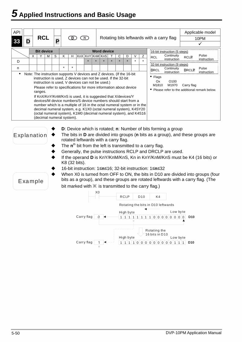
5 Applied Instructions and Basic Usage
DVP-10PM Application Manual 5-50
API Applicable model 10PM 33 D RCL P Rotating bits leftwards with a carry flag
Bit device Word device X Y M S K H KnX KnY KnM KnS T C D V Z
D * * * * * * * *
n * * Note: The instruction supports V devices and Z devices. (If the 16-bit
instruction is used, Z devices can not be used. If the 32-bit instruction is used, V devices can not be used.) Please refer to specifications for more information about device ranges. If KnX/KnY/KnM/KnS is used, it is suggested that X/devices/Y devices/M device numbers/S device numbers should start from a number which is a multiple of 16 in the octal numeral system or in the decimal numeral system, e.g. K1X0 (octal numeral system), K4SY20 (octal numeral system), K1M0 (decimal numeral system), and K4S16 (decimal numeral system).
16-bit instruction (5 steps) RCL Continuity
instruction RCLP Pulse instruction
32-bit instruction (9 steps)
DRCL Continuity instruction DRCLP Pulse
instruction Flags
Ox O100 M1810 M1970 Carry flag Please refer to the additional remark below.
Exp lanat ion The bits in D are divided into groups (n bits as a group), and these groups are rotated leftwards with a carry flag.
D: Device which is rotated; n: Number of bits forming a group
The nth bit from the left is transmitted to a carry flag. Generally, the pulse instructions RCLP and DRCLP are used. If the operand D is KnY/KnM/KnS, Kn in KnY/KnM/KnS must be K4 (16 bits) or
K8 (32 bits). 16-bit instruction: 1≤n≤16; 32-bit instruction: 1≤n≤32
Example
When X0 is turned from OFF to ON, the bits in D10 are divided into groups (four bits as a group), and these groups are rotated leftwards with a carry flag. (The bit marked with ※ is transmitted to the carry flag.)
Hi gh byte
Low by te
Rotating the bits in D10 leftwards
Rotating the 16 bits in D10
Carry flag
Carry flag Low by te
Hi gh byte
X0D10 K4
1 1 1 1 1 1 0 0 0 0 01 1 0 0 0
1 1 0 0 0 0 0 100 00 11 1 1
D10
D10
RCLP
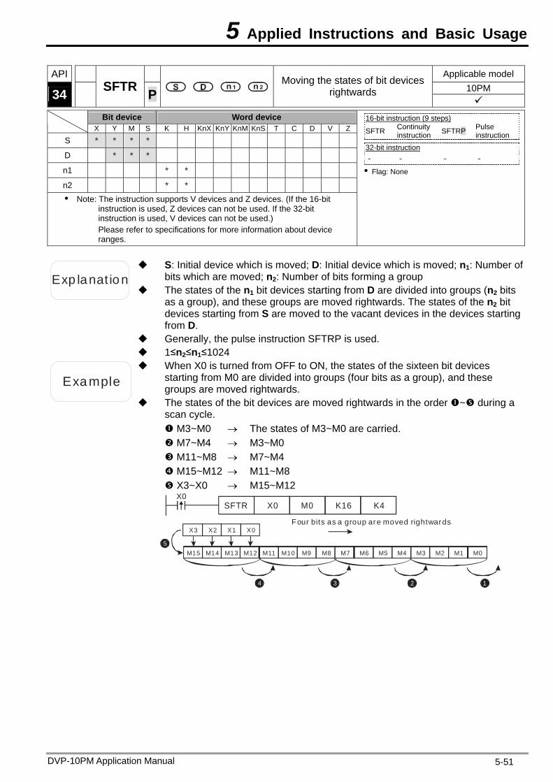
5 Applied Instructions and Basic Usage
DVP-10PM Application Manual 5-51
API Applicable model 10PM 34 SFTR P
Moving the states of bit devices rightwards
Bit device Word device
X Y M S K H KnX KnY KnM KnS T C D V Z
S * * * *
D * * *
n1 * *
n2 * * Note: The instruction supports V devices and Z devices. (If the 16-bit
instruction is used, Z devices can not be used. If the 32-bit instruction is used, V devices can not be used.) Please refer to specifications for more information about device ranges.
16-bit instruction (9 steps) SFTR Continuity
instruction SFTRP Pulse instruction
32-bit instruction - - - -
Flag: None
Exp lanat ion
S: Initial device which is moved; D: Initial device which is moved; n1: Number of bits which are moved; n2: Number of bits forming a group
The states of the n1 bit devices starting from D are divided into groups (n2 bits as a group), and these groups are moved rightwards. The states of the n2 bit devices starting from S are moved to the vacant devices in the devices starting from D.
Generally, the pulse instruction SFTRP is used. 1≤n2≤n1≤1024
Example
When X0 is turned from OFF to ON, the states of the sixteen bit devices starting from M0 are divided into groups (four bits as a group), and these groups are moved rightwards.
The states of the bit devices are moved rightwards in the order ~ during a scan cycle. M3~M0 The states of M3~M0 are carried. M7~M4 M3~M0 M11~M8 M7~M4 M15~M12 M11~M8 X3~X0 M15~M12
X0SFTR X0 M0 K16 K4
Four bits as a group are moved rightwards.
X3 X2 X1 X0
M15 M14 M13 M12 M11 M10 M9 M8 M7 M6
34
5M5 M4 M3 M2 M1 M0
12
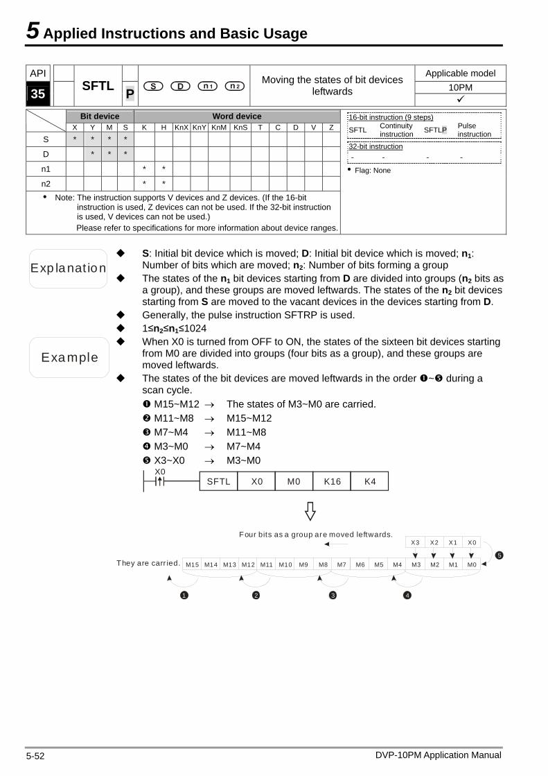
5 Applied Instructions and Basic Usage
DVP-10PM Application Manual 5-52
API Applicable model 10PM 35 SFTL P
Moving the states of bit devices leftwards
Bit device Word device
X Y M S K H KnX KnY KnM KnS T C D V Z
S * * * *
D * * *
n1 * *
n2 * * Note: The instruction supports V devices and Z devices. (If the 16-bit
instruction is used, Z devices can not be used. If the 32-bit instruction is used, V devices can not be used.) Please refer to specifications for more information about device ranges.
16-bit instruction (9 steps) SFTL Continuity
instruction SFTLP Pulse instruction
32-bit instruction - - - -
Flag: None
Exp lanat ion
S: Initial bit device which is moved; D: Initial bit device which is moved; n1: Number of bits which are moved; n2: Number of bits forming a group
The states of the n1 bit devices starting from D are divided into groups (n2 bits as a group), and these groups are moved leftwards. The states of the n2 bit devices starting from S are moved to the vacant devices in the devices starting from D.
Generally, the pulse instruction SFTRP is used. 1≤n2≤n1≤1024
Example
When X0 is turned from OFF to ON, the states of the sixteen bit devices starting from M0 are divided into groups (four bits as a group), and these groups are moved leftwards.
The states of the bit devices are moved leftwards in the order ~ during a scan cycle. M15~M12 The states of M3~M0 are carried. M11~M8 M15~M12 M7~M4 M11~M8 M3~M0 M7~M4 X3~X0 M3~M0
X0SFTL X0 M0 K16 K4
1 2 3
M15 M14 M13 M12 M11 M10 M9 M8 M7
X3 X2 X1 X0
4
5M6 M5 M4 M3 M2 M1 M0
Four bits as a group are moved leftwards.
They are carr ied.
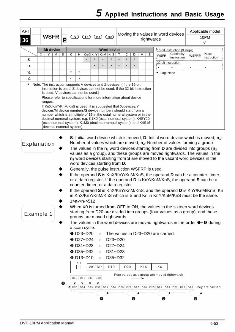
5 Applied Instructions and Basic Usage
DVP-10PM Application Manual 5-53
API Applicable model 10PM 36 WSFR P
Moving the values in word devices rightwards
Bit device Word device
X Y M S K H KnX KnY KnM KnS T C D V Z
S * * * * * * *
D * * * * * *
n1 * *
n2 * * Note: The instruction supports V devices and Z devices. (If the 16-bit
instruction is used, Z devices can not be used. If the 32-bit instruction is used, V devices can not be used.) Please refer to specifications for more information about device ranges. If KnX/KnY/KnM/KnS is used, it is suggested that X/devices/Y devices/M device numbers/S device numbers should start from a number which is a multiple of 16 in the octal numeral system or in the decimal numeral system, e.g. K1X0 (octal numeral system), K4SY20 (octal numeral system), K1M0 (decimal numeral system), and K4S16 (decimal numeral system).
16-bit instruction (9 steps) WSFR Continuity
instruction WSFRP Pulse instruction
32-bit instruction - - - -
Flag: None
Exp lanat ion
S: Initial word device which is moved; D: Initial word device which is moved; n1: Number of values which are moved; n2: Number of values forming a group
The values in the n1 word devices starting from D are divided into groups (n2 values as a group), and these groups are moved rightwards. The values in the n2 word devices starting from S are moved to the vacant word devices in the word devices starting from D.
Generally, the pulse instruction WSFRP is used. If the operand S is KnX/KnY/KnM/KnS, the operand D can be a counter, timer,
or a data register. If the operand D is KnY/KnM/KnS, the operand S can be a counter, timer, or a data register.
If the operand S is KnX/KnY/KnM/KnS, and the operand D is KnY/KnM/KnS, Kn in KnX/KnY/KnM/KnS which is S and Kn in KnY/KnM/KnS must be the same.
1≤n2≤n1≤512
Examp le 1
When X0 is turned from OFF to ON, the values in the sixteen word devices starting from D20 are divided into groups (four values as a group), and these groups are moved rightwards.
The values in the word devices are moved rightwards in the order ~ during a scan cycle. D23~D20 The values in D23~D20 are carried. D27~D24 D23~D20 D31~D28 D27~D24 D35~D32 D31~D28 D13~D10 D35~D32
X0WSFRP D10 K16D20 K4
They are carr ied.
D13 D12 D11 D10
D35 D34 D33 D32 D31 D30 D29 D28 D27
34
5D26 D25 D24 D23 D22 D21 D20
12
Four val ues as a group are moved rightwards.
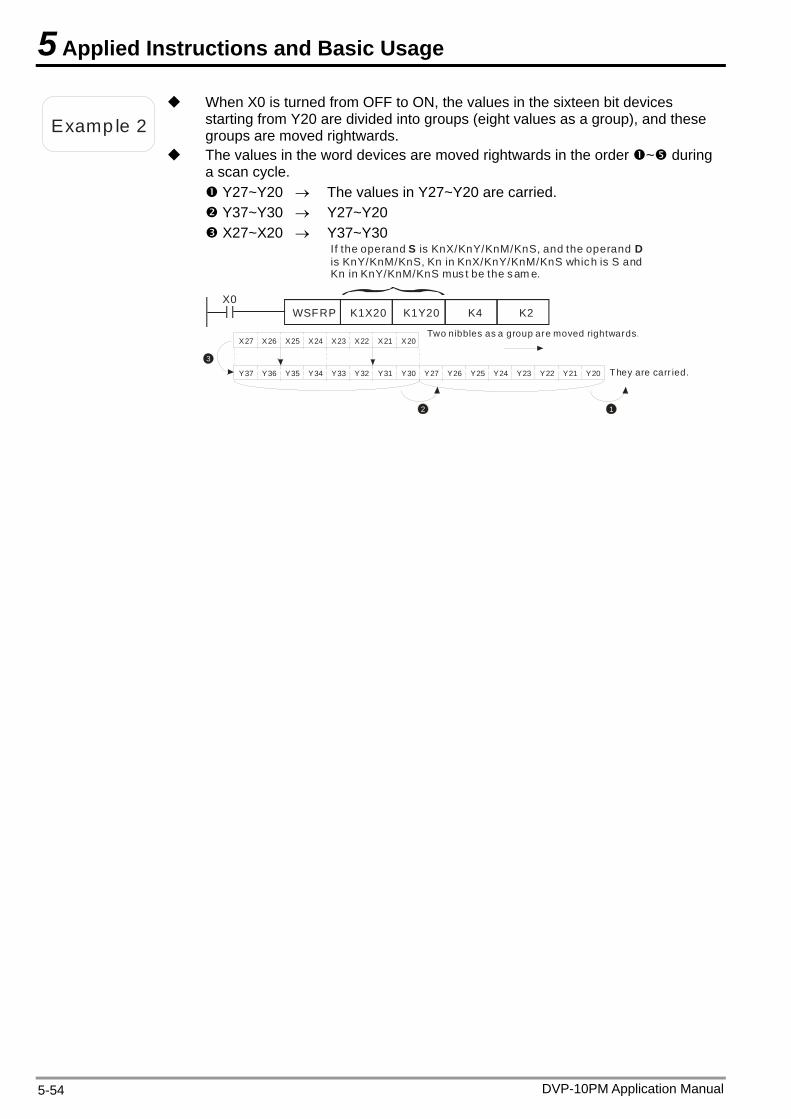
5 Applied Instructions and Basic Usage
Examp le 2
When X0 is turned from OFF to ON, the values in the sixteen bit devices starting from Y20 are divided into groups (eight values as a group), and these groups are moved rightwards.
The values in the word devices are moved rightwards in the order ~ during a scan cycle. Y27~Y20 The values in Y27~Y20 are carried. Y37~Y30 Y27~Y20 X27~X20 Y37~Y30
X0WSFRP K1X20 K1Y20
If the operand is KnX/KnY/KnM/KnS, and the operand is KnY/KnM/KnS, Kn in KnX/KnY/KnM/KnS which is S and Kn in KnY/KnM/KnS mus t be the sam e.
S D
K4 K2
They are carr ied.Y37 Y36 Y35 Y34 Y33 Y32 Y31 Y30 Y27
2
3
X27 X26 X25 X24 X23 X22 X21 X20
Y26 Y25 Y24 Y23 Y22 Y21 Y20
Two nibbles as a group are moved rightwards.
1
DVP-10PM Application Manual 5-54
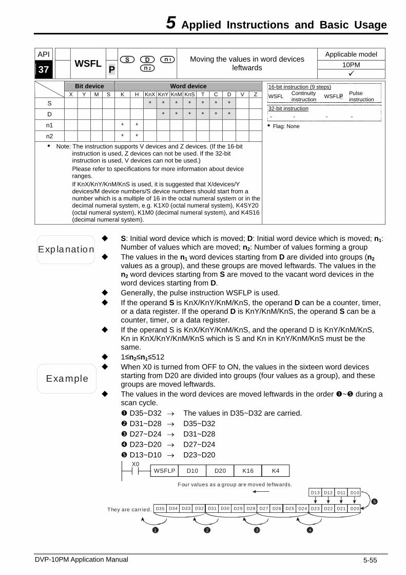
5 Applied Instructions and Basic Usage
DVP-10PM Application Manual 5-55
API Applicable model 10PM 37 WSFL P
Moving the values in word devices leftwards
Bit device Word device
X Y M S K H KnX KnY KnM KnS T C D V Z
S * * * * * * *
D * * * * * *
n1 * *
n2 * * Note: The instruction supports V devices and Z devices. (If the 16-bit
instruction is used, Z devices can not be used. If the 32-bit instruction is used, V devices can not be used.) Please refer to specifications for more information about device ranges. If KnX/KnY/KnM/KnS is used, it is suggested that X/devices/Y devices/M device numbers/S device numbers should start from a number which is a multiple of 16 in the octal numeral system or in the decimal numeral system, e.g. K1X0 (octal numeral system), K4SY20 (octal numeral system), K1M0 (decimal numeral system), and K4S16 (decimal numeral system).
16-bit instruction (9 steps) WSFL Continuity
instruction WSFLP Pulse instruction
32-bit instruction - - - -
Flag: None
Exp lanat ion
S: Initial word device which is moved; D: Initial word device which is moved; n1: Number of values which are moved; n2: Number of values forming a group
The values in the n1 word devices starting from D are divided into groups (n2 values as a group), and these groups are moved leftwards. The values in the n2 word devices starting from S are moved to the vacant word devices in the word devices starting from D.
Generally, the pulse instruction WSFLP is used. If the operand S is KnX/KnY/KnM/KnS, the operand D can be a counter, timer,
or a data register. If the operand D is KnY/KnM/KnS, the operand S can be a counter, timer, or a data register.
If the operand S is KnX/KnY/KnM/KnS, and the operand D is KnY/KnM/KnS, Kn in KnX/KnY/KnM/KnS which is S and Kn in KnY/KnM/KnS must be the same.
1≤n2≤n1≤512
Example
When X0 is turned from OFF to ON, the values in the sixteen word devices starting from D20 are divided into groups (four values as a group), and these groups are moved leftwards.
The values in the word devices are moved leftwards in the order ~ during a scan cycle. D35~D32 The values in D35~D32 are carried. D31~D28 D35~D32 D27~D24 D31~D28 D23~D20 D27~D24 D13~D10 D23~D20
X0WSFLP D10 K16D20 K4
They are carr ied.
Four values as a group are moved leftwards.D13
D20
1 2 3 4
5
D12 D11 D10
D21D22D23D24D25D26D27D28D29D30D31D32D33D34D35
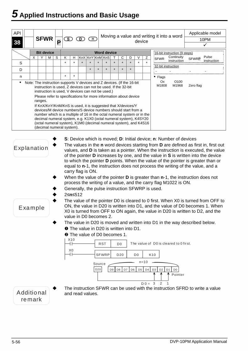
5 Applied Instructions and Basic Usage
DVP-10PM Application Manual 5-56
API Applicable model 10PM 38 SFWR P
Moving a value and writing it into a word device
Bit device Word device
X Y M S K H KnX KnY KnM KnS T C D V Z
S * * * * * * * * * * *
D * * * * * *
n * * Note: The instruction supports V devices and Z devices. (If the 16-bit
instruction is used, Z devices can not be used. If the 32-bit instruction is used, V devices can not be used.) Please refer to specifications for more information about device ranges. If KnX/KnY/KnM/KnS is used, it is suggested that X/devices/Y devices/M device numbers/S device numbers should start from a number which is a multiple of 16 in the octal numeral system or in the decimal numeral system, e.g. K1X0 (octal numeral system), K4SY20 (octal numeral system), K1M0 (decimal numeral system), and K4S16 (decimal numeral system).
16-bit instruction (9 steps) SFWR Continuity
instruction SFWRP Pulse instruction
32-bit instruction - - - -
Flags Ox O100
M1808 M1968 Zero flag
Exp lanat ion The values in the n word devices starting from D are defined as first in, first out values, and D is taken as a pointer. When the instruction is executed, the value of the pointer D increases by one, and the value in S is written into the device to which the pointer D points. When the value of the pointer is greater than or equal to n-1, the instruction does not process the writing of the value, and a carry flag is ON.
S: Device which is moved; D: Initial device; n: Number of devices
When the value of the pointer D is greater than n-1, the instruction does not process the writing of a value, and the carry flag M1022 is ON.
Generally, the pulse instruction SFWRP is used. 2≤n≤512
Example
The value of the pointer D0 is cleared to 0 first. When X0 is turned from OFF to ON, the value in D20 is written into D1, and the value of D0 becomes 1. When X0 is turned from OFF to ON again, the value in D20 is written to D2, and the value in D0 becomes 2.
The value in D20 is moved and written into D1 in the way described below. The value in D20 is written into D1. The value of D0 becomes 1.
RST D0
SFWRP D20 D0
X10
X0K10
The value of D0 is cleared to 0 f ir st.
D20 D9 D8 D7 D6 D5 D4 D3 D2 D1 D0
n=10
D 0 = 3 2 1
Pointer
Sourc e
Additional
remark
The instruction SFWR can be used with the instruction SFRD to write a value and read values.
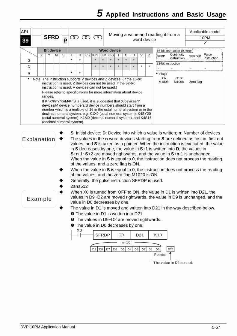
5 Applied Instructions and Basic Usage
DVP-10PM Application Manual 5-57
API Applicable model 10PM 39 SFRD P
Moving a value and reading it from a word device
Bit device Word device
X Y M S K H KnX KnY KnM KnS T C D V Z
S * * * * * * * *
D * * * * * * * *
n * * Note: The instruction supports V devices and Z devices. (If the 16-bit
instruction is used, Z devices can not be used. If the 32-bit instruction is used, V devices can not be used.) Please refer to specifications for more information about device ranges. If KnX/KnY/KnM/KnS is used, it is suggested that X/devices/Y devices/M device numbers/S device numbers should start from a number which is a multiple of 16 in the octal numeral system or in the decimal numeral system, e.g. K1X0 (octal numeral system), K4SY20 (octal numeral system), K1M0 (decimal numeral system), and K4S16 (decimal numeral system).
16-bit instruction (9 steps) SFRD Continuity
instruction SFRD P Pulse instruction
32-bit instruction - - - -
Flags Ox O100
M1808 M1968 Zero flag
Exp lanat ion The values in the n word devices starting from S are defined as first in, first out values, and S is taken as a pointer. When the instruction is executed, the value in S decreases by one, the value in S+1 is written into D, the values in S+n-1~S+2 are moved rightwards, and the value in S+n-1 is unchanged. When the value in S is equal to 0, the instruction does not process the reading of the values, and a zero flag is ON.
S: Initial device; D: Device into which a value is written; n: Number of devices
When the value in S is equal to 0, the instruction does not process the reading of the values, and the zero flag M1020 is ON.
Generally, the pulse instruction SFRDP is used. 2≤n≤512
Example
When X0 is turned from OFF to ON, the value in D1 is written into D21, the values in D9~D2 are moved rightwards, the value in D9 is unchanged, and the value in D0 decreases by one.
The value in D1 is moved and written into D21 in the way described below. The value in D1 is written into D21. The values in D9~D2 are moved rightwards. The value in D0 decreases by one.
X0SFRDP D0 D21 K10
Pointer
n=10
D21
The value i n D1 is read.
D9 D8 D7 D6 D5 D4 D3 D2 D1 D0
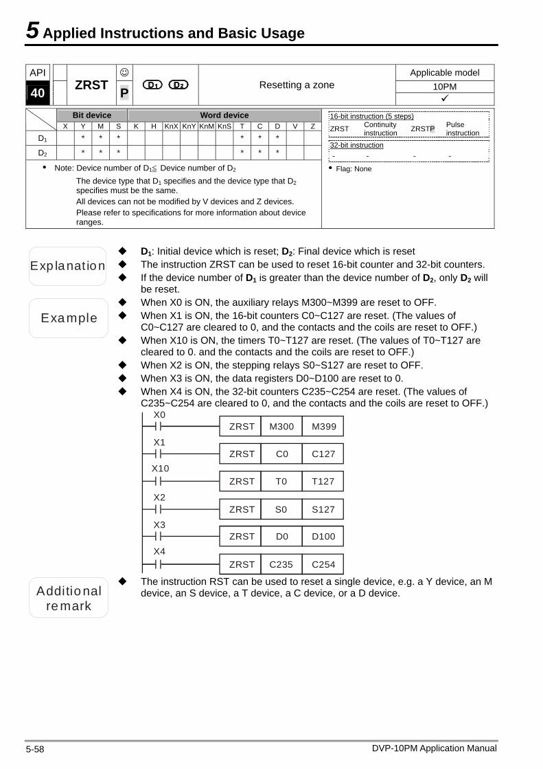
5 Applied Instructions and Basic Usage
DVP-10PM Application Manual 5-58
API Applicable model 10PM 40 ZRST P Resetting a zone
Bit device Word device X Y M S K H KnX KnY KnM KnS T C D V Z
D1 * * * * * *
D2 * * * * * *
Note: Device number of D1≦ Device number of D2 The device type that D1 specifies and the device type that D2 specifies must be the same. All devices can not be modified by V devices and Z devices. Please refer to specifications for more information about device ranges.
16-bit instruction (5 steps) ZRST Continuity
instruction ZRSTP Pulse instruction
32-bit instruction - - - -
Flag: None
Exp lanat ion The instruction ZRST can be used to reset 16-bit counter and 32-bit counters.
D1: Initial device which is reset; D2: Final device which is reset
If the device number of D1 is greater than the device number of D2, only D2 will be reset.
Example When X1 is ON, the 16-bit counters C0~C127 are reset. (The values of C0~C127 are cleared to 0, and the contacts and the coils are reset to OFF.)
When X0 is ON, the auxiliary relays M300~M399 are reset to OFF.
When X10 is ON, the timers T0~T127 are reset. (The values of T0~T127 are cleared to 0. and the contacts and the coils are reset to OFF.)
When X2 is ON, the stepping relays S0~S127 are reset to OFF. When X3 is ON, the data registers D0~D100 are reset to 0. When X4 is ON, the 32-bit counters C235~C254 are reset. (The values of
C235~C254 are cleared to 0, and the contacts and the coils are reset to OFF.)
ZRST M300 M399
ZRST C0 C127
ZRST T0 T127
ZRST S0 S127
ZRST D0 D100
ZRST C235 C254
X0
X1
X10
X2
X3
X4
Additional
remark
The instruction RST can be used to reset a single device, e.g. a Y device, an M device, an S device, a T device, a C device, or a D device.
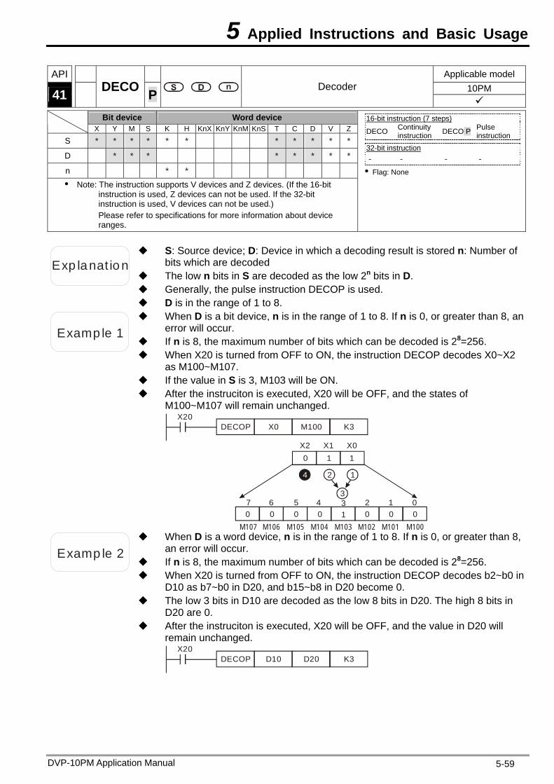
5 Applied Instructions and Basic Usage
DVP-10PM Application Manual 5-59
API Applicable model 10PM 41 DECO P Decoder
Bit device Word device X Y M S K H KnX KnY KnM KnS T C D V Z
S * * * * * * * * * * *
D * * * * * * * *
n * * Note: The instruction supports V devices and Z devices. (If the 16-bit
instruction is used, Z devices can not be used. If the 32-bit instruction is used, V devices can not be used.) Please refer to specifications for more information about device ranges.
16-bit instruction (7 steps) DECO Continuity
instruction DECO P Pulse instruction
32-bit instruction - - - -
Flag: None
Exp lanat ion
S: Source device; D: Device in which a decoding result is stored n: Number of bits which are decoded
The low n bits in S are decoded as the low 2n bits in D. Generally, the pulse instruction DECOP is used. D is in the range of 1 to 8.
Examp le 1
When D is a bit device, n is in the range of 1 to 8. If n is 0, or greater than 8, an error will occur.
If n is 8, the maximum number of bits which can be decoded is 28=256. When X20 is turned from OFF to ON, the instruction DECOP decodes X0~X2
as M100~M107. If the value in S is 3, M103 will be ON. After the instruciton is executed, X20 will be OFF, and the states of
M100~M107 will remain unchanged.
DECOP X0 K3M100X20
X2 X1 X0
M107 M106 M105 M104 M103 M102 M101 M100
0 1 1
10 0 0 0 0 0 037 6 5 4 2 1 0
4 12
3
Examp le 2 If n is 8, the maximum number of bits which can be decoded is 28=256.
When D is a word device, n is in the range of 1 to 8. If n is 0, or greater than 8, an error will occur.
When X20 is turned from OFF to ON, the instruction DECOP decodes b2~b0 in D10 as b7~b0 in D20, and b15~b8 in D20 become 0.
The low 3 bits in D10 are decoded as the low 8 bits in D20. The high 8 bits in D20 are 0.
After the instruciton is executed, X20 will be OFF, and the value in D20 will remain unchanged.
DECOP D10 K3D20X20
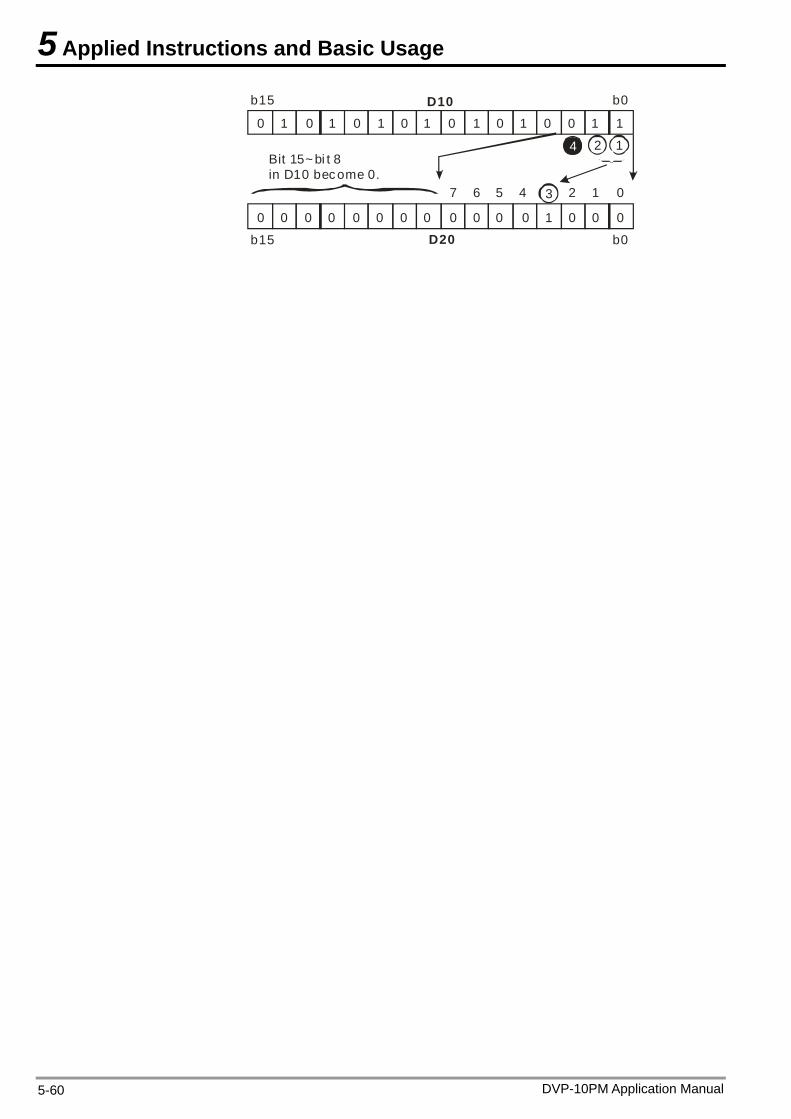
5 Applied Instructions and Basic Usage
0 0 0 0 0 0 0 01 1 1 1 1 1 1 1
0 0 0 0 0 0 0 0 0 0 0 0 0 0 01
4 2 1
3
b15 b0
Bit 15~ bi t 8 in D10 bec ome 0.
b15 b0
D10
D20
7 6 5 4 2 1 0
DVP-10PM Application Manual 5-60
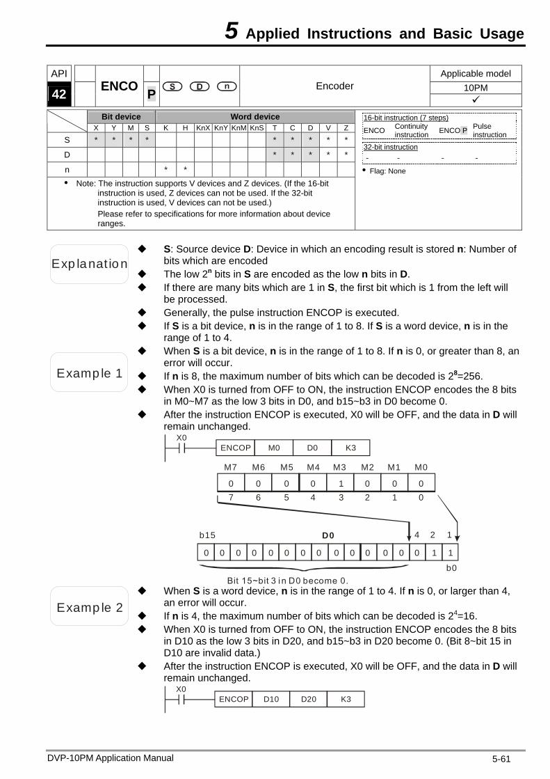
5 Applied Instructions and Basic Usage
DVP-10PM Application Manual 5-61
API Applicable model 10PM 42 ENCO P Encoder
Bit device Word device X Y M S K H KnX KnY KnM KnS T C D V Z
S * * * * * * * * *
D * * * * *
n * * Note: The instruction supports V devices and Z devices. (If the 16-bit
instruction is used, Z devices can not be used. If the 32-bit instruction is used, V devices can not be used.) Please refer to specifications for more information about device ranges.
16-bit instruction (7 steps) ENCO Continuity
instruction ENCO P Pulse instruction
32-bit instruction - - - -
Flag: None
Exp lanat ion
S: Source device D: Device in which an encoding result is stored n: Number of bits which are encoded
The low 2n bits in S are encoded as the low n bits in D. If there are many bits which are 1 in S, the first bit which is 1 from the left will
be processed. Generally, the pulse instruction ENCOP is executed. If S is a bit device, n is in the range of 1 to 8. If S is a word device, n is in the
range of 1 to 4.
Examp le 1 If n is 8, the maximum number of bits which can be decoded is 28=256.
When S is a bit device, n is in the range of 1 to 8. If n is 0, or greater than 8, an error will occur.
When X0 is turned from OFF to ON, the instruction ENCOP encodes the 8 bits in M0~M7 as the low 3 bits in D0, and b15~b3 in D0 become 0.
After the instruction ENCOP is executed, X0 will be OFF, and the data in D will remain unchanged.
ENCOP M0 K3D0X0
b15
Bit 15~bit 3 i n D0 become 0.b0
D0 4 2 1
0 0 0 0 1 0 0 07 6 5 4 3 2 1 0
M7 M6 M5 M4 M3 M2 M1 M0
0 0 0 0 0 0 0 0 0 0 0 0 0 1 10
Examp le 2 If n is 4, the maximum number of bits which can be decoded is 24=16.
When S is a word device, n is in the range of 1 to 4. If n is 0, or larger than 4, an error will occur.
When X0 is turned from OFF to ON, the instruction ENCOP encodes the 8 bits in D10 as the low 3 bits in D20, and b15~b3 in D20 become 0. (Bit 8~bit 15 in D10 are invalid data.)
After the instruction ENCOP is executed, X0 will be OFF, and the data in D will remain unchanged.
ENCOP D10 K3D20X0
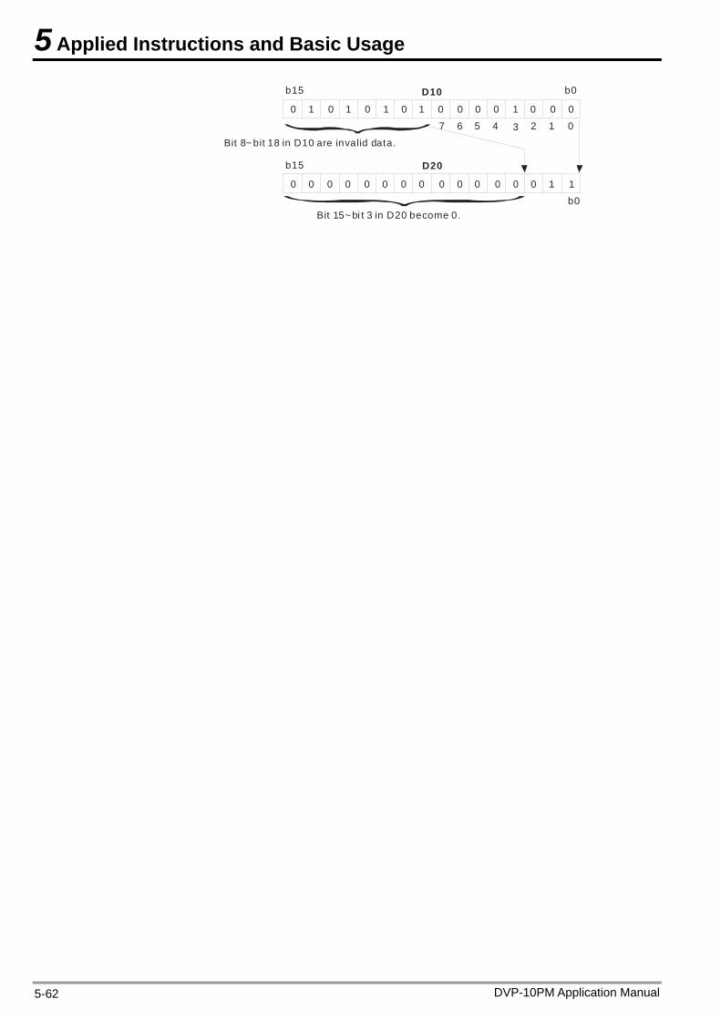
5 Applied Instructions and Basic Usage
0 0 0 0 0 0 01 1 1 1 1
0 0 0 0 0 0 0 0 0 0 0 0 0 1
3
b15 b0
Bit 8~ bit 18 in D10 are invalid data.
b15
b0
D10
D20
7 6 5 4 2 1 0
Bit 15~ bi t 3 in D20 become 0.
10
0 0 0 0
DVP-10PM Application Manual 5-62
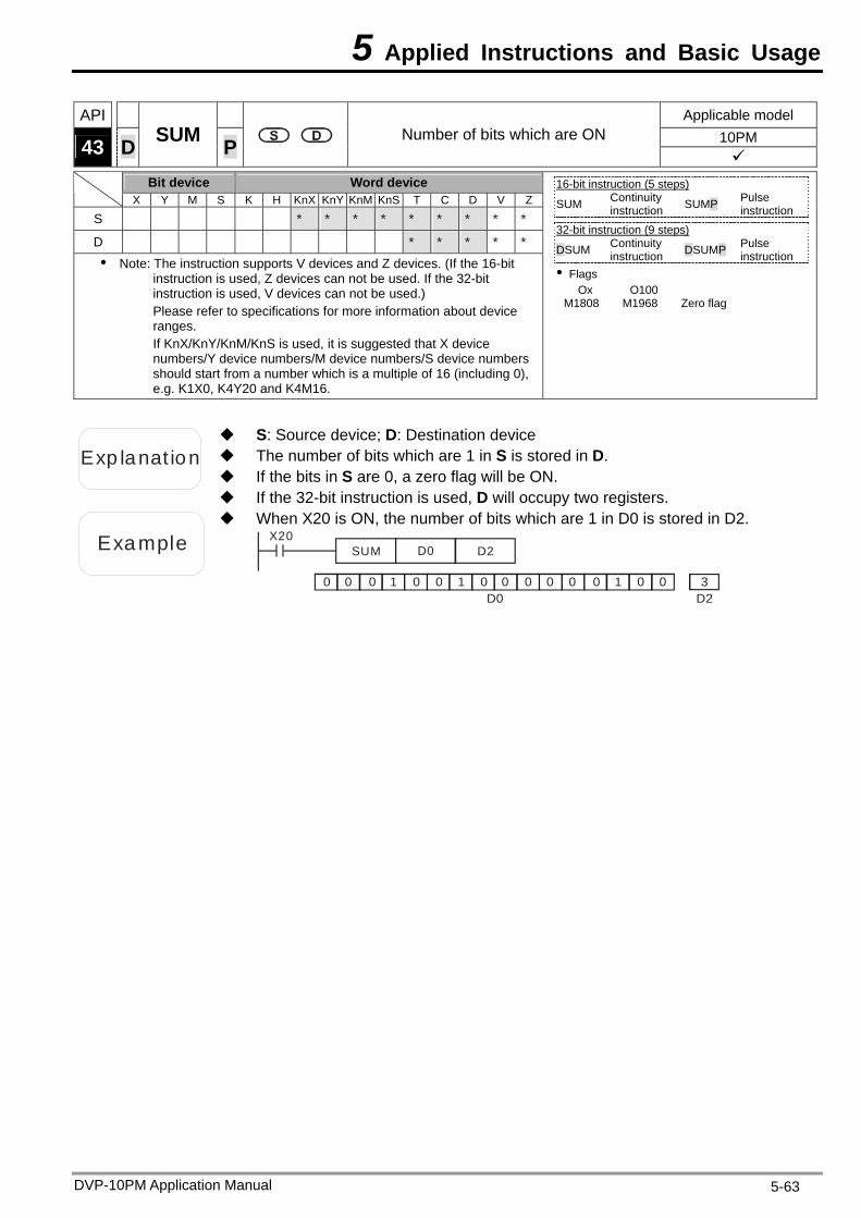
5 Applied Instructions and Basic Usage
API Applicable model 10PM 43 D SUM P Number of bits which are ON
Bit device Word device X Y M S K H KnX KnY KnM KnS T C D V Z
S * * * * * * * * *
D * * * * *
Note: The instruction supports V devices and Z devices. (If the 16-bit instruction is used, Z devices can not be used. If the 32-bit instruction is used, V devices can not be used.) Please refer to specifications for more information about device ranges. If KnX/KnY/KnM/KnS is used, it is suggested that X device numbers/Y device numbers/M device numbers/S device numbers should start from a number which is a multiple of 16 (including 0), e.g. K1X0, K4Y20 and K4M16.
16-bit instruction (5 steps) SUM Continuity
instruction SUMP Pulse instruction
32-bit instruction (9 steps)
DSUM Continuity instruction DSUMP Pulse
instruction Flags
Ox O100 M1808 M1968 Zero flag
Exp lanat ion The number of bits which are 1 in S is stored in D.
S: Source device; D: Destination device
If the bits in S are 0, a zero flag will be ON. If the 32-bit instruction is used, D will occupy two registers.
Example
When X20 is ON, the number of bits which are 1 in D0 is stored in D2. X20
SUM D0 D2
0 0 0 0 0 0 01 1 10 0 0 00 0 3D2D0
DVP-10PM Application Manual 5-63
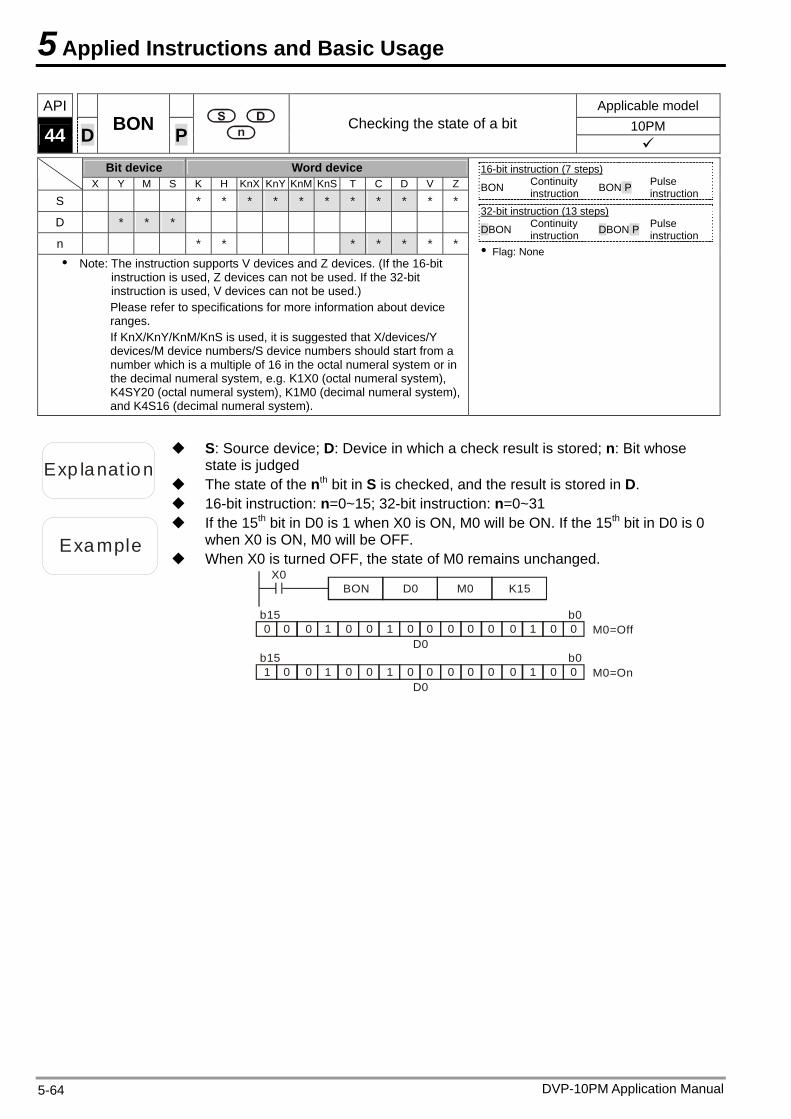
5 Applied Instructions and Basic Usage
API Applicable model 10PM 44 D BON P
Checking the state of a bit
Bit device Word device X Y M S K H KnX KnY KnM KnS T C D V Z
S * * * * * * * * * * *
D * * *
n * * * * * * *
Note: The instruction supports V devices and Z devices. (If the 16-bit instruction is used, Z devices can not be used. If the 32-bit instruction is used, V devices can not be used.) Please refer to specifications for more information about device ranges. If KnX/KnY/KnM/KnS is used, it is suggested that X/devices/Y devices/M device numbers/S device numbers should start from a number which is a multiple of 16 in the octal numeral system or in the decimal numeral system, e.g. K1X0 (octal numeral system), K4SY20 (octal numeral system), K1M0 (decimal numeral system), and K4S16 (decimal numeral system).
16-bit instruction (7 steps) BON Continuity
instruction BON P Pulse instruction
32-bit instruction (13 steps)
DBON Continuity instruction DBON P Pulse
instruction Flag: None
Exp lanat ion
S: Source device; D: Device in which a check result is stored; n: Bit whose state is judged
The state of the nth bit in S is checked, and the result is stored in D. 16-bit instruction: n=0~15; 32-bit instruction: n=0~31
Example
If the 15th bit in D0 is 1 when X0 is ON, M0 will be ON. If the 15th bit in D0 is 0 when X0 is ON, M0 will be OFF.
When X0 is turned OFF, the state of M0 remains unchanged. X0
BON D0 M0
0 0 0 0 0 0 01 1 10 0 0 00 0D0
K15
b0M0=Off
b15
1 0 0 0 0 0 01 1 10 0 0 00 0D0
b0M0=On
b15
DVP-10PM Application Manual 5-64
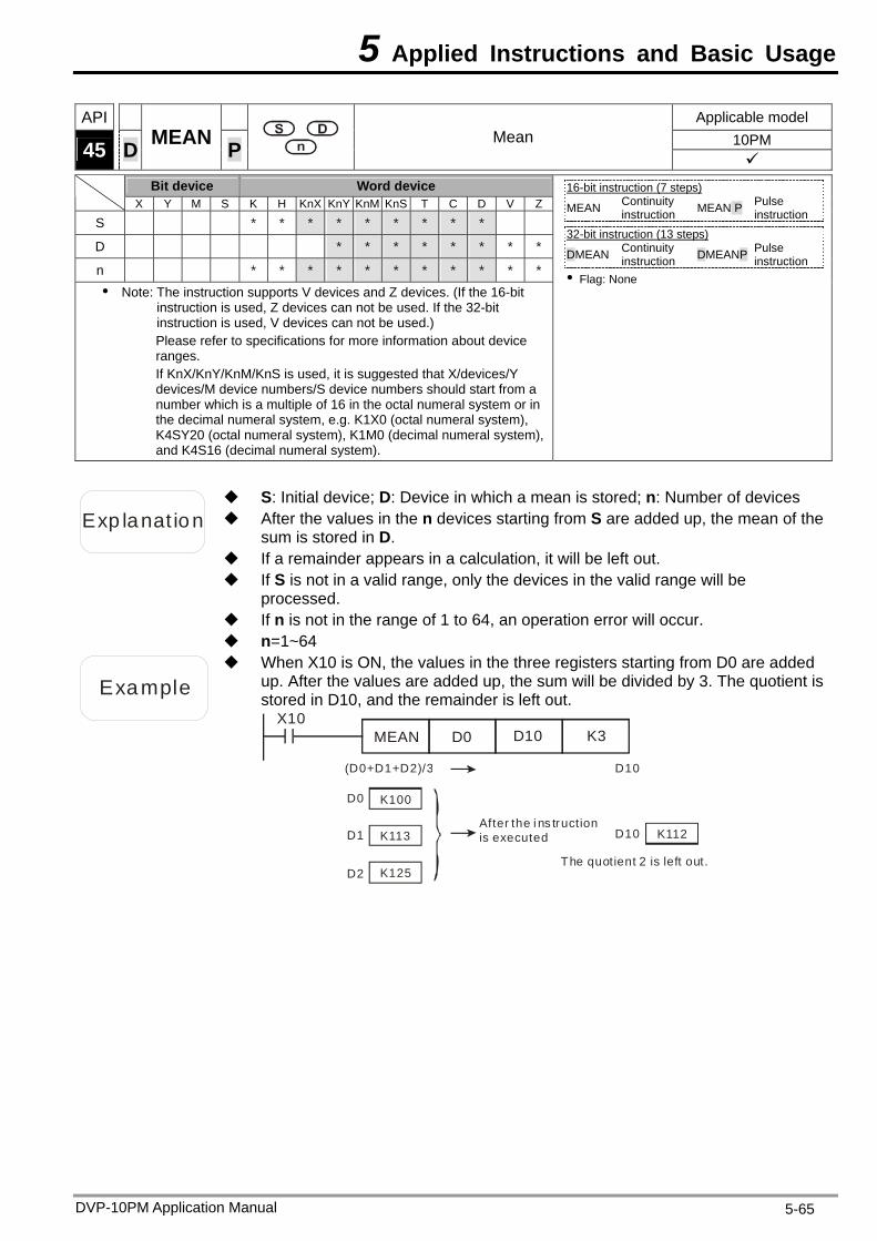
5 Applied Instructions and Basic Usage
API Applicable model 10PM 45 D MEAN P
Mean
Bit device Word device X Y M S K H KnX KnY KnM KnS T C D V Z
S * * * * * * * * *
D * * * * * * * *
n * * * * * * * * * * *
Note: The instruction supports V devices and Z devices. (If the 16-bit instruction is used, Z devices can not be used. If the 32-bit instruction is used, V devices can not be used.) Please refer to specifications for more information about device ranges. If KnX/KnY/KnM/KnS is used, it is suggested that X/devices/Y devices/M device numbers/S device numbers should start from a number which is a multiple of 16 in the octal numeral system or in the decimal numeral system, e.g. K1X0 (octal numeral system), K4SY20 (octal numeral system), K1M0 (decimal numeral system), and K4S16 (decimal numeral system).
16-bit instruction (7 steps) MEAN Continuity
instruction MEAN P Pulse instruction
32-bit instruction (13 steps)
DMEAN Continuity instruction DMEANP Pulse
instruction Flag: None
Exp lanat ion After the values in the n devices starting from S are added up, the mean of the sum is stored in D.
S: Initial device; D: Device in which a mean is stored; n: Number of devices
If a remainder appears in a calculation, it will be left out. If S is not in a valid range, only the devices in the valid range will be
processed. If n is not in the range of 1 to 64, an operation error will occur. n=1~64
Example
When X10 is ON, the values in the three registers starting from D0 are added up. After the values are added up, the sum will be divided by 3. The quotient is stored in D10, and the remainder is left out.
X10MEAN D0 D10 K3
D0
D1
D2
D10
K112
K100
K113
K125
(D0+D1+D2)/3
D10After the i ns truction is executed
The quotient 2 is left out.
DVP-10PM Application Manual 5-65
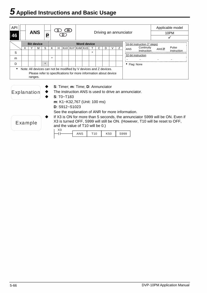
5 Applied Instructions and Basic Usage
API Applicable model 10PM 46 ANS P
Driving an annunciator
Bit device Word device X Y M S K H KnX KnY KnM KnS T C D V Z
S *
m *
D * Note: All devices can not be modified by V devices and Z devices.
Please refer to specifications for more information about device ranges.
16-bit instruction (7 steps) ANS Continuity
instruction ANS P Pulse instruction
32-bit instruction - - - -
Flag: None
Exp lanat ion The instruction ANS is used to drive an annunciator.
S: Timer; m: Time; D: Annunciator
S: T0~T183 m: K1~K32,767 (Unit: 100 ms) D: S912~S1023 See the explanation of ANR for more information.
Example
If X3 is ON for more than 5 seconds, the annunciator S999 will be ON. Even if X3 is turned OFF, S999 will still be ON. (However, T10 will be reset to OFF, and the value of T10 will be 0.)
X3ANS T10 K50 S999
DVP-10PM Application Manual 5-66
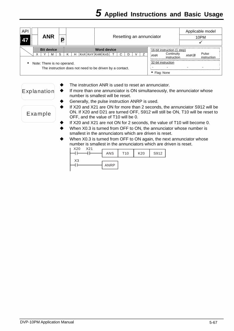
5 Applied Instructions and Basic Usage
API Applicable model 10PM 47 ANR P
Resetting an annunciator
Bit device Word device X Y M S K H KnX KnY KnM KnS T C D V Z
Note: There is no operand. The instruction does not need to be driven by a contact.
16-bit instruction (1 step) ANR Continuity
instruction ANR P Pulse instruction
32-bit instruction - - - -
Flag: None
Exp lanat ion If more than one annunciator is ON simultaneously, the annunciator whose number is smallest will be reset.
The instruction ANR is used to reset an annunciator.
Generally, the pulse instruction ANRP is used.
Example
If X20 and X21 are ON for more than 2 seconds, the annunciator S912 will be ON. If X20 and D21 are turned OFF, S912 will still be ON, T10 will be reset to OFF, and the value of T10 will be 0.
If X20 and X21 are not ON for 2 seconds, the value of T10 will become 0. When X0.3 is turned from OFF to ON, the annunciator whose number is
smallest in the annunciators which are driven is reset. When X0.3 is turned from OFF to ON again, the next annunciator whose
number is smallest in the annunciators which are driven is reset. X20
ANS T10 K20 S912X21
X3ANRP
DVP-10PM Application Manual 5-67
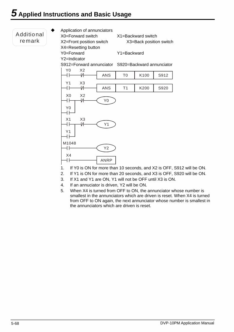
5 Applied Instructions and Basic Usage
Additional remark
Application of annunciators X0=Forward switch X1=Backward switch X2=Front position switch X3=Back position switch X4=Resetting button Y0=Forward Y1=Backward Y2=Indicator S912=Forward annunciator S920=Backward annunciator
Y0ANS T0 K100 S912
X2
X4ANRP
Y1ANS T1 K200 S920
X3
X0Y0
X2
M1048Y2
Y0
X1Y1
X3
Y1
1. If Y0 is ON for more than 10 seconds, and X2 is OFF, S912 will be ON. 2. If Y1 is ON for more than 20 seconds, and X3 is OFF, S920 will be ON. 3. If X1 and Y1 are ON, Y1 will not be OFF until X3 is ON. 4. If an annuciator is driven, Y2 will be ON. 5. When X4 is turned from OFF to ON, the annunciator whose number is
smallest in the annunciators which are driven is reset. When X4 is turned from OFF to ON again, the next annunciator whose number is smallest in the annunciators which are driven is reset.
DVP-10PM Application Manual 5-68
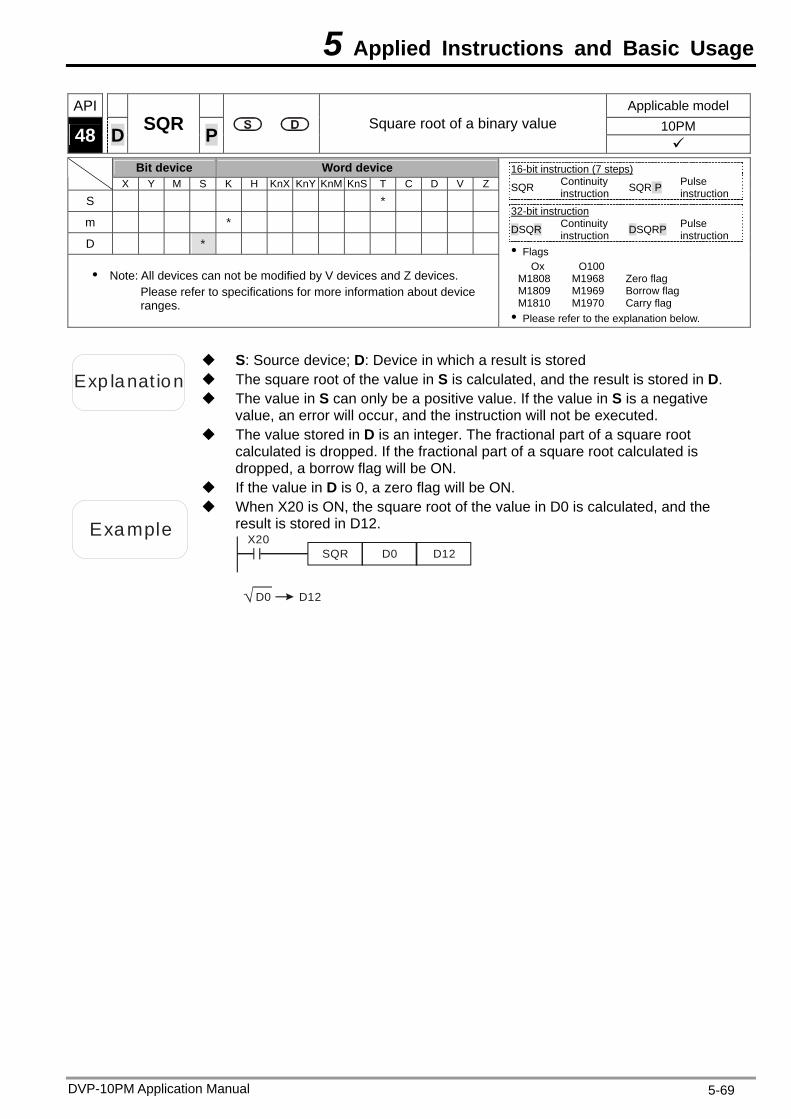
5 Applied Instructions and Basic Usage
API Applicable model 10PM 48 D SQR P Square root of a binary value
Bit device Word device X Y M S K H KnX KnY KnM KnS T C D V Z
S *
m *
D *
Note: All devices can not be modified by V devices and Z devices. Please refer to specifications for more information about device ranges.
16-bit instruction (7 steps) SQR Continuity
instruction SQR P Pulse instruction
32-bit instruction
DSQR Continuity instruction DSQRP Pulse
instruction Flags
Ox O100 M1808 M1968 Zero flag M1809 M1969 Borrow flag M1810 M1970 Carry flag Please refer to the explanation below.
Exp lanat ion The square root of the value in S is calculated, and the result is stored in D.
S: Source device; D: Device in which a result is stored
The value in S can only be a positive value. If the value in S is a negative value, an error will occur, and the instruction will not be executed.
The value stored in D is an integer. The fractional part of a square root calculated is dropped. If the fractional part of a square root calculated is dropped, a borrow flag will be ON.
If the value in D is 0, a zero flag will be ON.
Example
When X20 is ON, the square root of the value in D0 is calculated, and the result is stored in D12.
X20SQR D0 D12
D0 D12
DVP-10PM Application Manual 5-69
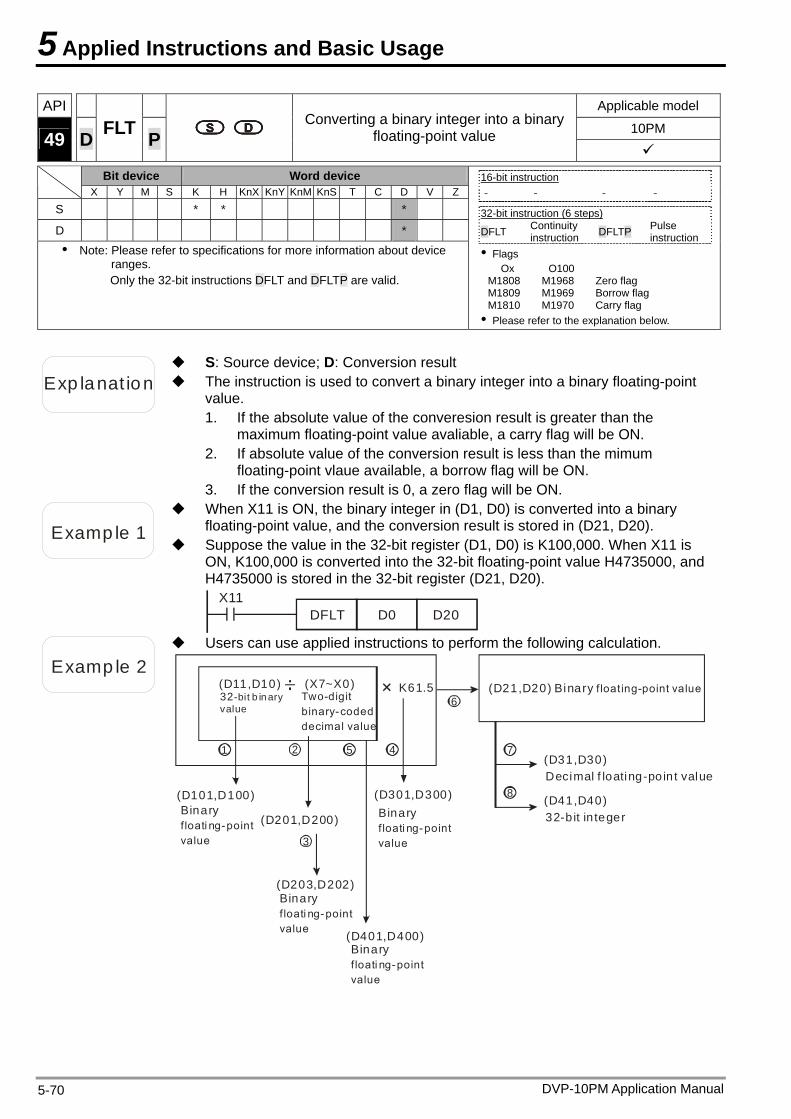
5 Applied Instructions and Basic Usage
API Applicable model
10PM 49 D FLT P
Converting a binary integer into a binary floating-point value
Bit device Word device
X Y M S K H KnX KnY KnM KnS T C D V Z
S * * *
D * Note: Please refer to specifications for more information about device
ranges. Only the 32-bit instructions DFLT and DFLTP are valid.
16-bit instruction - - - -
32-bit instruction (6 steps) DFLT Continuity
instruction DFLTP Pulse instruction
Flags Ox O100
M1808 M1968 Zero flag M1809 M1969 Borrow flag M1810 M1970 Carry flag Please refer to the explanation below.
Exp lanat ion The instruction is used to convert a binary integer into a binary floating-point value.
S: Source device; D: Conversion result
1. If the absolute value of the converesion result is greater than the maximum floating-point value avaliable, a carry flag will be ON.
2. If absolute value of the conversion result is less than the mimum floating-point vlaue available, a borrow flag will be ON.
3. If the conversion result is 0, a zero flag will be ON.
Examp le 1
When X11 is ON, the binary integer in (D1, D0) is converted into a binary floating-point value, and the conversion result is stored in (D21, D20).
Suppose the value in the 32-bit register (D1, D0) is K100,000. When X11 is ON, K100,000 is converted into the 32-bit floating-point value H4735000, and H4735000 is stored in the 32-bit register (D21, D20).
X11DFLT D0 D20
Examp le 2
Users can use applied instructions to perform the following calculation.
32-bit b in aryvalue
Two-digit binary-coded decimal value
Binary f loati ng-point value
(D11,D10) (X7~X0) K61.5
1 2 5 4
6
7
8
3
(D21,D20) Binary f loating-point value
(D201,D200)
(D101,D100) (D301,D300)
(D31,D30)Decimal f loating-point value
(D41,D40)32-b it in teger
(D203,D202)
(D401,D400)
Binary f loati ng-point value
Binary f loati ng-point value
Binary f loati ng-point value
DVP-10PM Application Manual 5-70
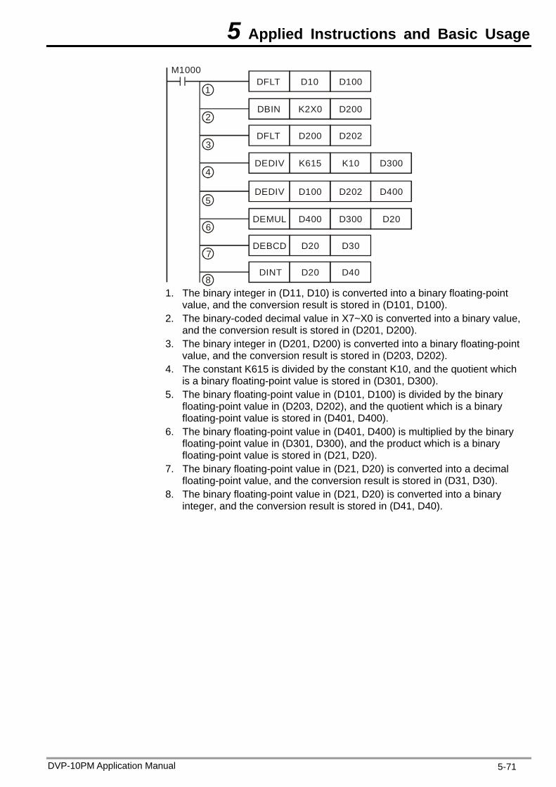
5 Applied Instructions and Basic Usage
M1000DFLT D10 D100
DEDIV K615 K10 D300
DBIN K2X0 D200
DFLT D200 D202
DEDIV D100 D202 D400
DEMUL D400 D300 D20
DEBCD D20 D30
DINT D20 D40
1
2
3
4
5
6
7
8 1. The binary integer in (D11, D10) is converted into a binary floating-point
value, and the conversion result is stored in (D101, D100). 2. The binary-coded decimal value in X7~X0 is converted into a binary value,
and the conversion result is stored in (D201, D200). 3. The binary integer in (D201, D200) is converted into a binary floating-point
value, and the conversion result is stored in (D203, D202). 4. The constant K615 is divided by the constant K10, and the quotient which
is a binary floating-point value is stored in (D301, D300). 5. The binary floating-point value in (D101, D100) is divided by the binary
floating-point value in (D203, D202), and the quotient which is a binary floating-point value is stored in (D401, D400).
6. The binary floating-point value in (D401, D400) is multiplied by the binary floating-point value in (D301, D300), and the product which is a binary floating-point value is stored in (D21, D20).
7. The binary floating-point value in (D21, D20) is converted into a decimal floating-point value, and the conversion result is stored in (D31, D30).
8. The binary floating-point value in (D21, D20) is converted into a binary integer, and the conversion result is stored in (D41, D40).
DVP-10PM Application Manual 5-71
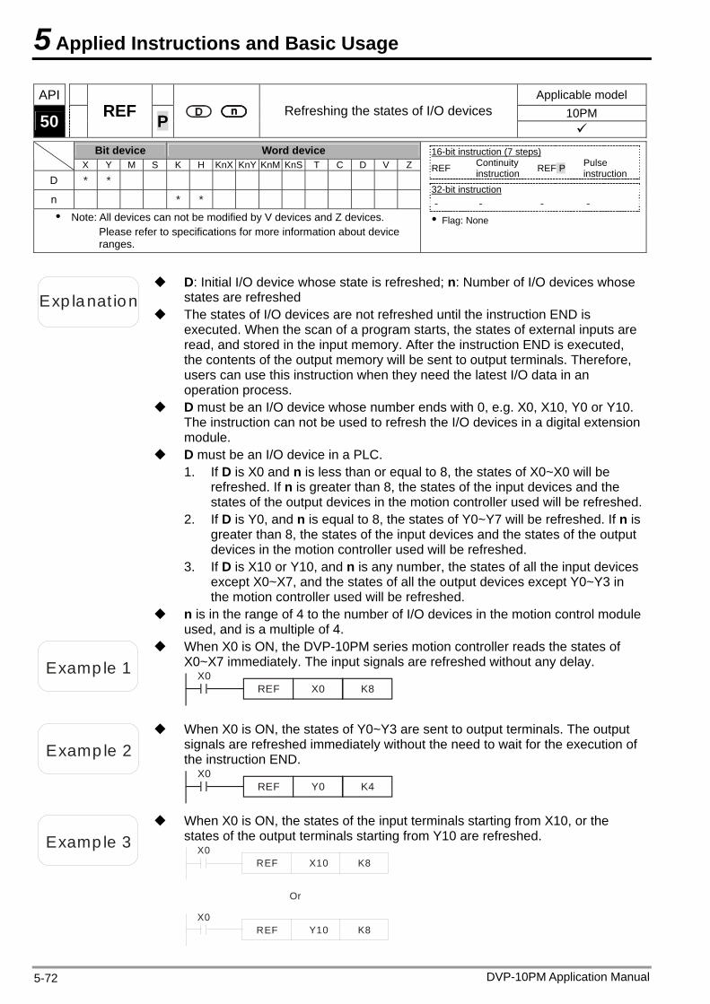
5 Applied Instructions and Basic Usage
API Applicable model 10PM 50 REF P Refreshing the states of I/O devices
Bit device Word device X Y M S K H KnX KnY KnM KnS T C D V Z
D * *
n * * Note: All devices can not be modified by V devices and Z devices.
Please refer to specifications for more information about device ranges.
16-bit instruction (7 steps) REF Continuity
instruction REF P Pulse instruction
32-bit instruction - - - -
Flag: None
Exp lanat ion
D: Initial I/O device whose state is refreshed; n: Number of I/O devices whose states are refreshed
The states of I/O devices are not refreshed until the instruction END is executed. When the scan of a program starts, the states of external inputs are read, and stored in the input memory. After the instruction END is executed, the contents of the output memory will be sent to output terminals. Therefore, users can use this instruction when they need the latest I/O data in an operation process.
D must be an I/O device whose number ends with 0, e.g. X0, X10, Y0 or Y10. The instruction can not be used to refresh the I/O devices in a digital extension module.
D must be an I/O device in a PLC. 1. If D is X0 and n is less than or equal to 8, the states of X0~X0 will be
refreshed. If n is greater than 8, the states of the input devices and the states of the output devices in the motion controller used will be refreshed.
2. If D is Y0, and n is equal to 8, the states of Y0~Y7 will be refreshed. If n is greater than 8, the states of the input devices and the states of the output devices in the motion controller used will be refreshed.
3. If D is X10 or Y10, and n is any number, the states of all the input devices except X0~X7, and the states of all the output devices except Y0~Y3 in the motion controller used will be refreshed.
n is in the range of 4 to the number of I/O devices in the motion control module used, and is a multiple of 4.
Examp le 1
When X0 is ON, the DVP-10PM series motion controller reads the states of X0~X7 immediately. The input signals are refreshed without any delay.
X0REF X0 K8
Examp le 2
When X0 is ON, the states of Y0~Y3 are sent to output terminals. The output signals are refreshed immediately without the need to wait for the execution of the instruction END.
X0REF Y0 K4
Examp le 3
When X0 is ON, the states of the input terminals starting from X10, or the states of the output terminals starting from Y10 are refreshed.
X0REF X10 K8
X0REF Y10 K8
Or
DVP-10PM Application Manual 5-72
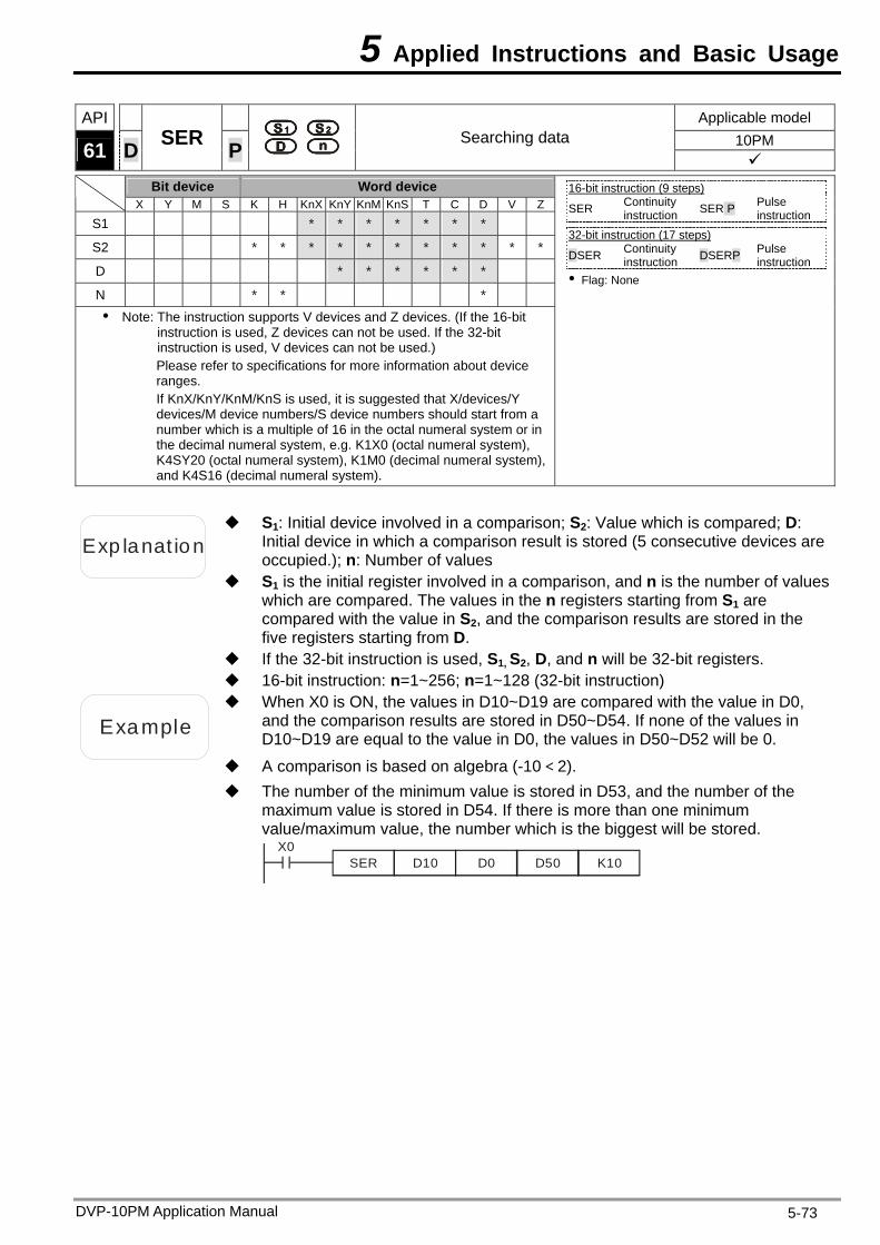
5 Applied Instructions and Basic Usage
API Applicable model 10PM 61 D SER P
Searching data
Bit device Word device X Y M S K H KnX KnY KnM KnS T C D V Z
S1 * * * * * * *
S2 * * * * * * * * * * *
D * * * * * *
N * * * Note: The instruction supports V devices and Z devices. (If the 16-bit
instruction is used, Z devices can not be used. If the 32-bit instruction is used, V devices can not be used.) Please refer to specifications for more information about device ranges. If KnX/KnY/KnM/KnS is used, it is suggested that X/devices/Y devices/M device numbers/S device numbers should start from a number which is a multiple of 16 in the octal numeral system or in the decimal numeral system, e.g. K1X0 (octal numeral system), K4SY20 (octal numeral system), K1M0 (decimal numeral system), and K4S16 (decimal numeral system).
16-bit instruction (9 steps) SER Continuity
instruction SER P Pulse instruction
32-bit instruction (17 steps)
DSER Continuity instruction DSERP Pulse
instruction Flag: None
Exp lanat ion
S1: Initial device involved in a comparison; S2: Value which is compared; D: Initial device in which a comparison result is stored (5 consecutive devices are occupied.); n: Number of values
S1 is the initial register involved in a comparison, and n is the number of values which are compared. The values in the n registers starting from S1 are compared with the value in S2, and the comparison results are stored in the five registers starting from D.
If the 32-bit instruction is used, S1, S2, D, and n will be 32-bit registers. 16-bit instruction: n=1~256; n=1~128 (32-bit instruction)
Example
When X0 is ON, the values in D10~D19 are compared with the value in D0, and the comparison results are stored in D50~D54. If none of the values in D10~D19 are equal to the value in D0, the values in D50~D52 will be 0.
A comparison is based on algebra (-10<2). The number of the minimum value is stored in D53, and the number of the
maximum value is stored in D54. If there is more than one minimum value/maximum value, the number which is the biggest will be stored.
X0SER D10 D0 D50 K10
DVP-10PM Application Manual 5-73
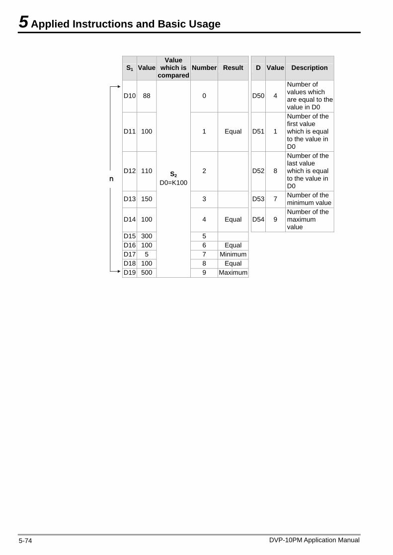
5 Applied Instructions and Basic Usage
DVP-10PM Application Manual 5-74
S1 Value Value
which is compared
Number Result D Value Description
D10 88 0 D50 4
Number of values which are equal to the value in D0
D11 100 1 Equal D51 1
Number of the first value which is equal to the value in D0
D12 110 2 D52 8
Number of the last value which is equal to the value in D0
D13 150 3 D53 7 Number of the minimum value
D14 100 4 Equal D54 9 Number of the maximum value
D15 300 5 D16 100 6 Equal D17 5 7 MinimumD18 100 8 Equal
n
D19 500
S2 D0=K100
9 Maximum
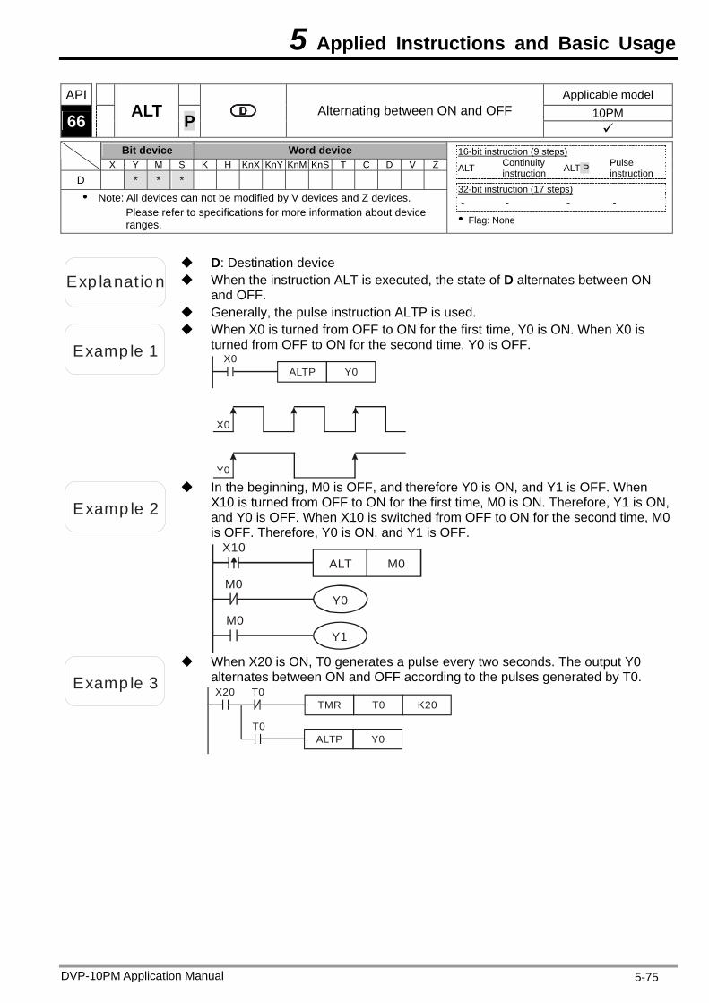
5 Applied Instructions and Basic Usage
API Applicable model 10PM 66 ALT P Alternating between ON and OFF
Bit device Word device X Y M S K H KnX KnY KnM KnS T C D V Z
D * * * Note: All devices can not be modified by V devices and Z devices.
Please refer to specifications for more information about device ranges.
16-bit instruction (9 steps) ALT Continuity
instruction ALT P Pulse instruction
32-bit instruction (17 steps) - - - -
Flag: None
Exp lanat ion When the instruction ALT is executed, the state of D alternates between ON and OFF.
D: Destination device
Generally, the pulse instruction ALTP is used.
Examp le 1
When X0 is turned from OFF to ON for the first time, Y0 is ON. When X0 is turned from OFF to ON for the second time, Y0 is OFF.
X0ALTP Y0
X0
Y0
Examp le 2
In the beginning, M0 is OFF, and therefore Y0 is ON, and Y1 is OFF. When X10 is turned from OFF to ON for the first time, M0 is ON. Therefore, Y1 is ON, and Y0 is OFF. When X10 is switched from OFF to ON for the second time, M0 is OFF. Therefore, Y0 is ON, and Y1 is OFF.
X10ALT M0
M0Y0
M0Y1
Examp le 3
When X20 is ON, T0 generates a pulse every two seconds. The output Y0 alternates between ON and OFF according to the pulses generated by T0. X20
TMR T0
ALTP Y0
K20T0
T0
DVP-10PM Application Manual 5-75
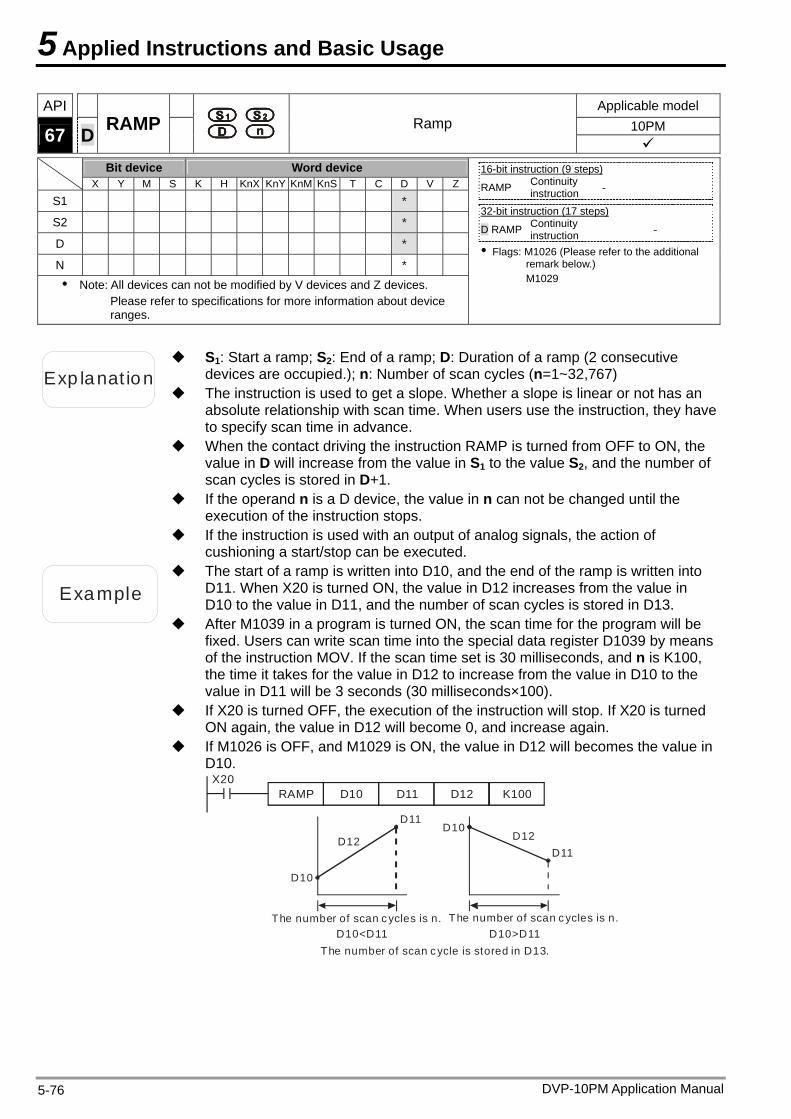
5 Applied Instructions and Basic Usage
API Applicable model 10PM
67 D RAMP Ramp
Bit device Word device
X Y M S K H KnX KnY KnM KnS T C D V Z
S1 *
S2 *
D *
N * Note: All devices can not be modified by V devices and Z devices.
Please refer to specifications for more information about device ranges.
16-bit instruction (9 steps) RAMP Continuity
instruction -
32-bit instruction (17 steps)
D RAMP Continuity instruction -
Flags: M1026 (Please refer to the additional remark below.) M1029
Exp lanat ion
S1: Start a ramp; S2: End of a ramp; D: Duration of a ramp (2 consecutive devices are occupied.); n: Number of scan cycles (n=1~32,767)
The instruction is used to get a slope. Whether a slope is linear or not has an absolute relationship with scan time. When users use the instruction, they have to specify scan time in advance.
When the contact driving the instruction RAMP is turned from OFF to ON, the value in D will increase from the value in S1 to the value S2, and the number of scan cycles is stored in D+1.
If the operand n is a D device, the value in n can not be changed until the execution of the instruction stops.
If the instruction is used with an output of analog signals, the action of cushioning a start/stop can be executed.
Example
The start of a ramp is written into D10, and the end of the ramp is written into D11. When X20 is turned ON, the value in D12 increases from the value in D10 to the value in D11, and the number of scan cycles is stored in D13.
After M1039 in a program is turned ON, the scan time for the program will be fixed. Users can write scan time into the special data register D1039 by means of the instruction MOV. If the scan time set is 30 milliseconds, and n is K100, the time it takes for the value in D12 to increase from the value in D10 to the value in D11 will be 3 seconds (30 milliseconds×100).
If X20 is turned OFF, the execution of the instruction will stop. If X20 is turned ON again, the value in D12 will become 0, and increase again.
If M1026 is OFF, and M1029 is ON, the value in D12 will becomes the value in D10.
X20RAMP D10 D11 D12 K100
D10
D12
D11
D11D12
D10
D10<D11 D10>D11 The number of scan c ycles is n.
The number of scan cycle is stored in D13.
The number of scan c ycles is n.
DVP-10PM Application Manual 5-76
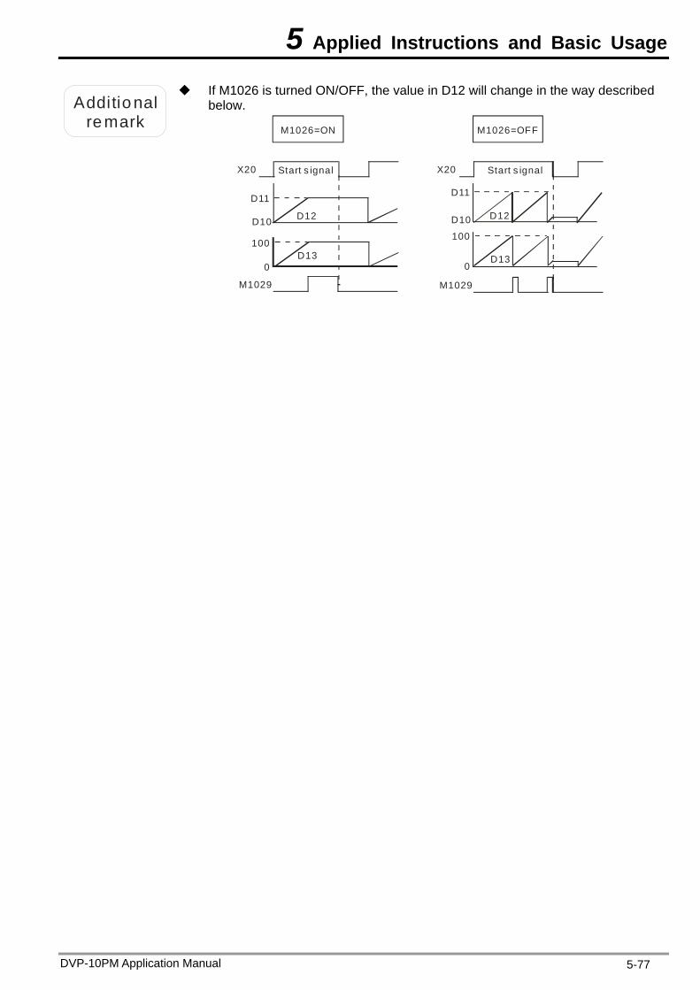
5 Applied Instructions and Basic Usage
DVP-10PM Application Manual 5-77
Additional
remark
If M1026 is turned ON/OFF, the value in D12 will change in the way described below.
X20
M1029
Start s ignal
M1026=ON
X20
D13
M1029
M1026=OFF
0D13
100
0
100
D11
D10 D12
D11
D10 D12
Start s ignal
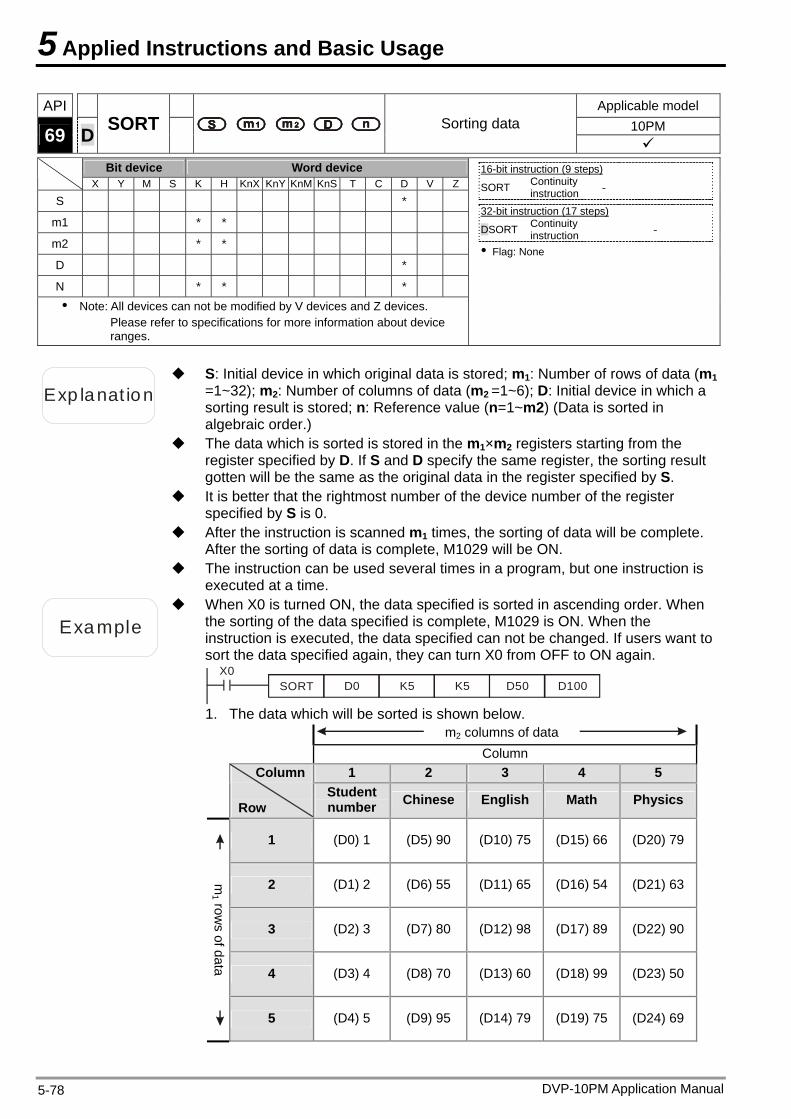
5 Applied Instructions and Basic Usage
API Applicable model 10PM 69 D SORT Sorting data
Bit device Word device X Y M S K H KnX KnY KnM KnS T C D V Z
S *
m1 * *
m2 * *
D *
N * * * Note: All devices can not be modified by V devices and Z devices.
Please refer to specifications for more information about device ranges.
16-bit instruction (9 steps) SORT Continuity
instruction -
32-bit instruction (17 steps)
DSORT Continuity instruction -
Flag: None
Exp lanat ion
S: Initial device in which original data is stored; m1: Number of rows of data (m1 =1~32); m2: Number of columns of data (m2 =1~6); D: Initial device in which a sorting result is stored; n: Reference value (n=1~m2) (Data is sorted in algebraic order.)
The data which is sorted is stored in the m1×m2 registers starting from the register specified by D. If S and D specify the same register, the sorting result gotten will be the same as the original data in the register specified by S.
It is better that the rightmost number of the device number of the register specified by S is 0.
After the instruction is scanned m1 times, the sorting of data will be complete. After the sorting of data is complete, M1029 will be ON.
The instruction can be used several times in a program, but one instruction is executed at a time.
Example
When X0 is turned ON, the data specified is sorted in ascending order. When the sorting of the data specified is complete, M1029 is ON. When the instruction is executed, the data specified can not be changed. If users want to sort the data specified again, they can turn X0 from OFF to ON again.
X0SORT D0 K5 K5 D50 D100
1. The data which will be sorted is shown below.
m2 columns of data
Column 1 2 3 4 5
Column
Row
Student number Chinese English Math Physics
1 (D0) 1 (D5) 90 (D10) 75 (D15) 66 (D20) 79
2 (D1) 2 (D6) 55 (D11) 65 (D16) 54 (D21) 63
3 (D2) 3 (D7) 80 (D12) 98 (D17) 89 (D22) 90
4 (D3) 4 (D8) 70 (D13) 60 (D18) 99 (D23) 50
m1 row
s of data 5 (D4) 5 (D9) 95 (D14) 79 (D19) 75 (D24) 69
DVP-10PM Application Manual 5-78
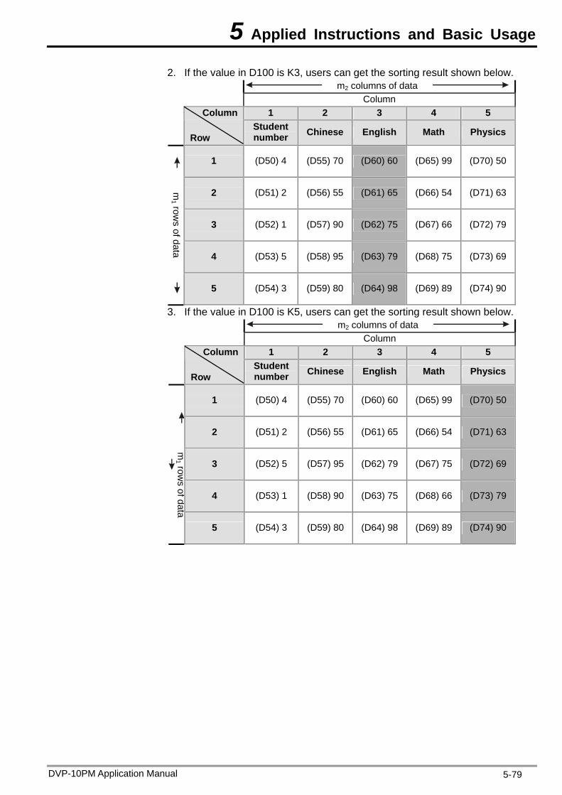
5 Applied Instructions and Basic Usage
2. If the value in D100 is K3, users can get the sorting result shown below. m2 columns of data
Column 1 2 3 4 5
Column
Row
Student number Chinese English Math Physics
1 (D50) 4 (D55) 70 (D60) 60 (D65) 99 (D70) 50
2 (D51) 2 (D56) 55 (D61) 65 (D66) 54 (D71) 63
3 (D52) 1 (D57) 90 (D62) 75 (D67) 66 (D72) 79
4 (D53) 5 (D58) 95 (D63) 79 (D68) 75 (D73) 69
m1 row
s of data 5 (D54) 3 (D59) 80 (D64) 98 (D69) 89 (D74) 90
3. If the value in D100 is K5, users can get the sorting result shown below. m2 columns of data
Column 1 2 3 4 5
Column
Row
Student number Chinese English Math Physics
1 (D50) 4 (D55) 70 (D60) 60 (D65) 99 (D70) 50
2 (D51) 2 (D56) 55 (D61) 65 (D66) 54 (D71) 63
3 (D52) 5 (D57) 95 (D62) 79 (D67) 75 (D72) 69
4 (D53) 1 (D58) 90 (D63) 75 (D68) 66 (D73) 79
m1 row
s of data
5 (D54) 3 (D59) 80 (D64) 98 (D69) 89 (D74) 90
DVP-10PM Application Manual 5-79
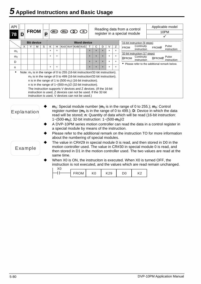
5 Applied Instructions and Basic Usage
API Applicable model 10PM 78 D FROM P
Reading data from a control register in a special module
Bit device Word device
X Y M S K H KnX KnY KnM KnS T C D V Z
m1 * * * * * * *
m2 * * * * * * *
D * * * * *
n * * * * * * *
Note: m1 is in the range of 0 to 255 (16-bit instruction/32-bit instruction).m2 is in the range of 0 to 499 (16-bit instruction/32-bit instruction).n is in the range of 1 to (500-m2) (16-bit instruction). n is in the range of 1~(500-m2)/2 (32-bit instruction). The instruction supports V devices and Z devices. (If the 16-bit instruction is used, Z devices can not be used. If the 32-bit instruction is used, V devices can not be used.)
16-bit instruction (9 steps) FROM Continuity
instruction FROMP Pulse instruction
32-bit instruction (17 steps)
DFROM Continuity instruction DFROMP Pulse
instruction Please refer to the additional remark below.
Exp lanat ion
m1: Special module number (m1 is in the range of 0 to 255.); m2: Control register number (m2 is in the range of 0 to 499.); D: Device in which the data read will be stored; n: Quantity of data which will be read (16-bit instruction: 1~(500-m2); 32-bit instruction: 1~(500-m2)/2
A DVP-10PM series motion controller can read the data in a control register in a special module by means of the instruction.
Please refer to the additional remark on the instruction TO for more information about the numbering of special modules.
Example
The value in CR#29 in special module 0 is read, and then stored in D0 in the motion controller used. The value in CR#30 in special module 0 is read, and then stored in D1 in the motion controller used. The two values are read at the same time.
When X0 is ON, the instruciton is executed. When X0 is turned OFF, the instruction is not executed, and the values which are read remain unchanged.
X0FROM K0 K29 D0 K2
DVP-10PM Application Manual 5-80
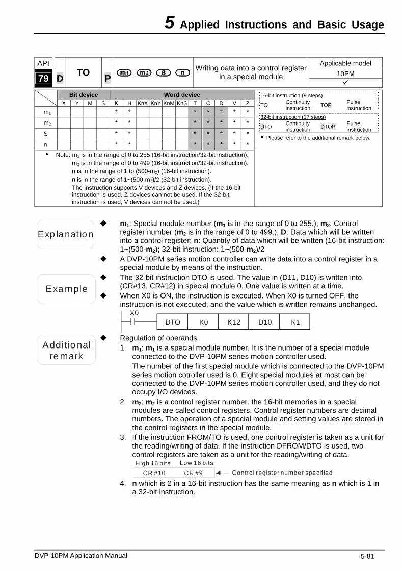
5 Applied Instructions and Basic Usage
API Applicable model
10PM 79 D TO P Writing data into a control register
in a special module
Bit device Word device X Y M S K H KnX KnY KnM KnS T C D V Z
m1 * * * * * * *
m2 * * * * * * *
S * * * * * * *
n * * * * * * *
Note: m1 is in the range of 0 to 255 (16-bit instruction/32-bit instruction).m2 is in the range of 0 to 499 (16-bit instruction/32-bit instruction).n is in the range of 1 to (500-m2) (16-bit instruction). n is in the range of 1~(500-m2)/2 (32-bit instruction). The instruction supports V devices and Z devices. (If the 16-bit instruction is used, Z devices can not be used. If the 32-bit instruction is used, V devices can not be used.)
16-bit instruction (9 steps) TO Continuity
instruction TOP Pulse instruction
32-bit instruction (17 steps)
DTO Continuity instruction DTOP Pulse
instruction Please refer to the additional remark below.
Exp lanat ion
m1: Special module number (m1 is in the range of 0 to 255.); m2: Control register number (m2 is in the range of 0 to 499.); D: Data which will be written into a control register; n: Quantity of data which will be written (16-bit instruction: 1~(500-m2); 32-bit instruction: 1~(500-m2)/2
A DVP-10PM series motion controller can write data into a control register in a special module by means of the instruction.
Example
The 32-bit instruction DTO is used. The value in (D11, D10) is written into (CR#13, CR#12) in special module 0. One value is written at a time.
When X0 is ON, the instruction is executed. When X0 is turned OFF, the instruction is not executed, and the value which is written remains unchanged.
X0DTO K0 K12 D10 K1
Additional remark
Regulation of operands 1. m1: m1 is a special module number. It is the number of a special module
connected to the DVP-10PM series motion controller used. The number of the first special module which is connected to the DVP-10PM series motion cotroller used is 0. Eight special modules at most can be connected to the DVP-10PM series motion controller used, and they do not occupy I/O devices.
2. m2: m2 is a control register number. the 16-bit memories in a special modules are called control registers. Control register numbers are decimal numbers. The operation of a special module and setting values are stored in the control registers in the special module.
3. If the instruction FROM/TO is used, one control register is taken as a unit for the reading/writing of data. If the instruction DFROM/DTO is used, two control registers are taken as a unit for the reading/writing of data. High 16 bits Low 16 bits
Control register number specif iedCR #10 CR #9 4. n which is 2 in a 16-bit instruction has the same meaning as n which is 1 in
a 32-bit instruction.
DVP-10PM Application Manual 5-81
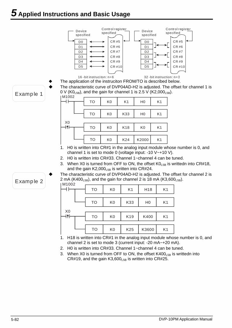
5 Applied Instructions and Basic Usage
D0D1D2D3D4D5
CR #5CR #6CR #7CR #8CR #9CR #10
16 -bit instruci ton: n= 6
Device specif ied
Control regis ter specif ied
D0D1D2D3D4D5
CR #5CR #6CR #7CR #8CR #9CR #10
32 -bit instruction: n= 3
Device specif ied
Control regis ter specif ied
The application of the instruciton FROM/TO is described below.
Examp le 1
The characteristic curve of DVP04AD-H2 is adjusted. The offset for channel 1 is 0 V (K0LSB), and the gain for channel 1 is 2.5 V (K2,000LSB). M1002
TO K0 K1 H0 K1
TO K0 K33 H0 K1
X0TO K0 K18 K0 K1
TO K0 K24 K2000 K1
1. H0 is written into CR#1 in the analog input module whose number is 0, and channel 1 is set to mode 0 (voltage input: -10 V~+10 V).
2. H0 is written into CR#33. Channel 1~channel 4 can be tuned. 3. When X0 is turned from OFF to ON, the offset K0LSB is writtedn into CR#18,
and the gain K2,000LSB is written into CR#24.
Examp le 2
The characteristic curve of DVP04AD-H2 is adjusted. The offset for channel 2 is 2 mA (K400LSB), and the gain for channel 2 is 18 mA (K3,600LSB). M1002
TO K0 K1 H18 K1
TO K0 K33 H0 K1
X0TO K0 K19 K400 K1
TO K0 K25 K3600 K1
1. H18 is written into CR#1 in the analog input module whose number is 0, and channel 2 is set to mode 3 (current input: -20 mA~+20 mA).
2. H0 is written into CR#33. Channel 1~channel 4 can be tuned. 3. When X0 is turned from OFF to ON, the offset K400LSB is writtedn into
CR#19, and the gain K3,600LSB is written into CR#25.
DVP-10PM Application Manual 5-82
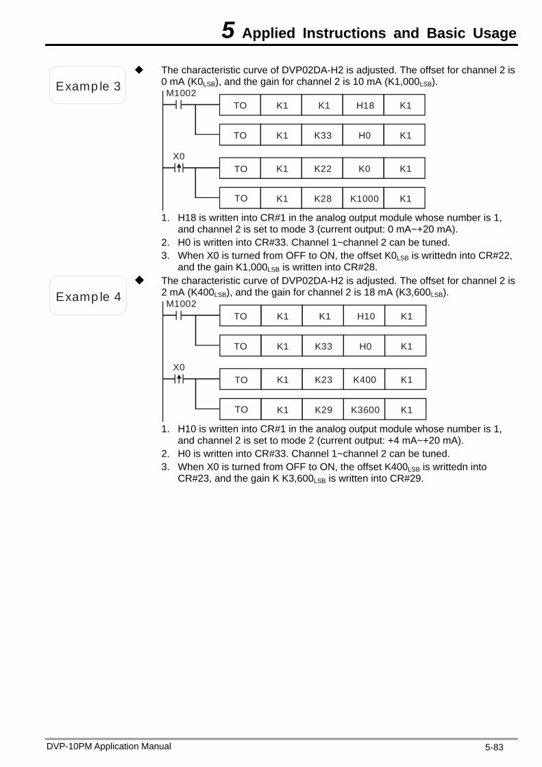
5 Applied Instructions and Basic Usage
Examp le 3
The characteristic curve of DVP02DA-H2 is adjusted. The offset for channel 2 is 0 mA (K0LSB), and the gain for channel 2 is 10 mA (K1,000LSB). M1002
TO K1 K1 H18 K1
TO K1 K33 H0 K1
X0TO K1 K22 K0 K1
TO K1 K28 K1000 K1
1. H18 is written into CR#1 in the analog output module whose number is 1, and channel 2 is set to mode 3 (current output: 0 mA~+20 mA).
2. H0 is written into CR#33. Channel 1~channel 2 can be tuned. 3. When X0 is turned from OFF to ON, the offset K0LSB is writtedn into CR#22,
and the gain K1,000LSB is written into CR#28.
Examp le 4
The characteristic curve of DVP02DA-H2 is adjusted. The offset for channel 2 is 2 mA (K400LSB), and the gain for channel 2 is 18 mA (K3,600LSB). M1002
TO K1 K1 H10 K1
TO K1 K33 H0 K1
X0TO K1 K23 K400 K1
TO K1 K29 K3600 K1
1. H10 is written into CR#1 in the analog output module whose number is 1, and channel 2 is set to mode 2 (current output: +4 mA~+20 mA).
2. H0 is written into CR#33. Channel 1~channel 2 can be tuned. 3. When X0 is turned from OFF to ON, the offset K400LSB is writtedn into
CR#23, and the gain K K3,600LSB is written into CR#29.
DVP-10PM Application Manual 5-83
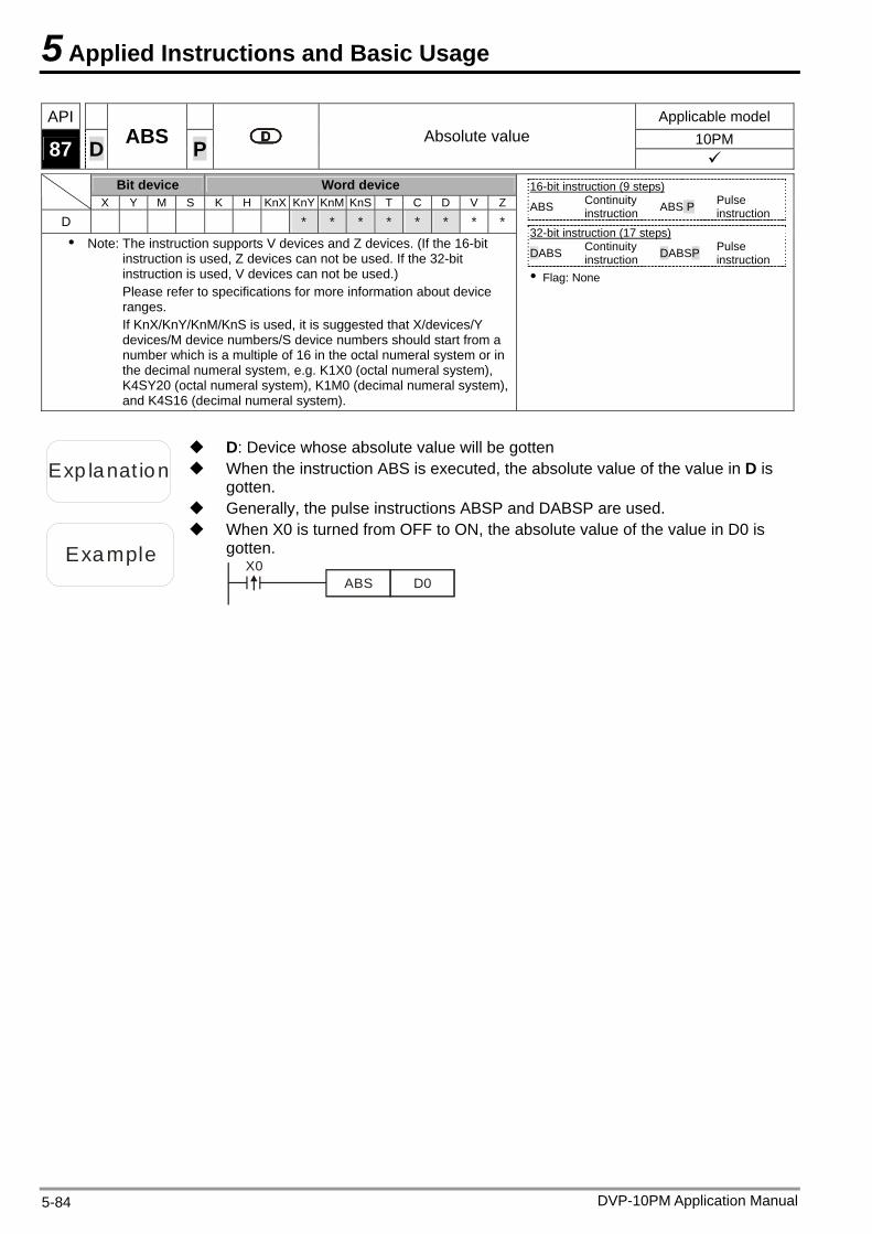
5 Applied Instructions and Basic Usage
API Applicable model 10PM 87 D ABS P Absolute value
Bit device Word device X Y M S K H KnX KnY KnM KnS T C D V Z
D * * * * * * * *
Note: The instruction supports V devices and Z devices. (If the 16-bit instruction is used, Z devices can not be used. If the 32-bit instruction is used, V devices can not be used.) Please refer to specifications for more information about device ranges. If KnX/KnY/KnM/KnS is used, it is suggested that X/devices/Y devices/M device numbers/S device numbers should start from a number which is a multiple of 16 in the octal numeral system or in the decimal numeral system, e.g. K1X0 (octal numeral system), K4SY20 (octal numeral system), K1M0 (decimal numeral system), and K4S16 (decimal numeral system).
16-bit instruction (9 steps) ABS Continuity
instruction ABS P Pulse instruction
32-bit instruction (17 steps)
DABS Continuity instruction DABSP Pulse
instruction Flag: None
Exp lanat ion When the instruction ABS is executed, the absolute value of the value in D is gotten.
D: Device whose absolute value will be gotten
Generally, the pulse instructions ABSP and DABSP are used.
Example
When X0 is turned from OFF to ON, the absolute value of the value in D0 is gotten.
X0ABS D0
DVP-10PM Application Manual 5-84
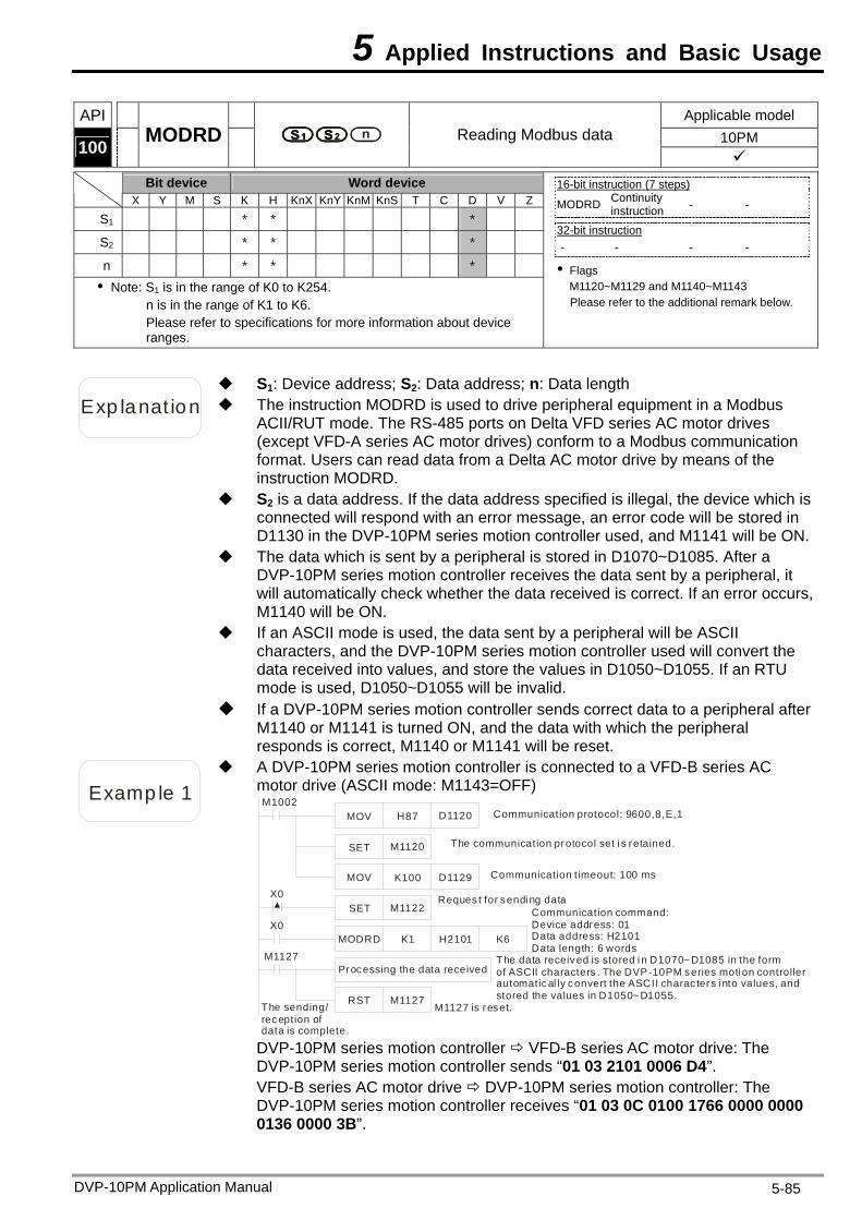
5 Applied Instructions and Basic Usage
API Applicable model 10PM 100 MODRD Reading Modbus data
Bit device Word device X Y M S K H KnX KnY KnM KnS T C D V Z
S1 * * *
S2 * * *
n * * * Note: S1 is in the range of K0 to K254.
n is in the range of K1 to K6. Please refer to specifications for more information about device ranges.
16-bit instruction (7 steps) MODRD Continuity
instruction - -
32-bit instruction - - - -
Flags M1120~M1129 and M1140~M1143 Please refer to the additional remark below.
Exp lanat ion The instruction MODRD is used to drive peripheral equipment in a Modbus ACII/RUT mode. The RS-485 ports on Delta VFD series AC motor drives (except VFD-A series AC motor drives) conform to a Modbus communication format. Users can read data from a Delta AC motor drive by means of the instruction MODRD.
S1: Device address; S2: Data address; n: Data length
S2 is a data address. If the data address specified is illegal, the device which is connected will respond with an error message, an error code will be stored in D1130 in the DVP-10PM series motion controller used, and M1141 will be ON.
The data which is sent by a peripheral is stored in D1070~D1085. After a DVP-10PM series motion controller receives the data sent by a peripheral, it will automatically check whether the data received is correct. If an error occurs, M1140 will be ON.
If an ASCII mode is used, the data sent by a peripheral will be ASCII characters, and the DVP-10PM series motion controller used will convert the data received into values, and store the values in D1050~D1055. If an RTU mode is used, D1050~D1055 will be invalid.
If a DVP-10PM series motion controller sends correct data to a peripheral after M1140 or M1141 is turned ON, and the data with which the peripheral responds is correct, M1140 or M1141 will be reset.
Examp le 1
A DVP-10PM series motion controller is connected to a VFD-B series AC motor drive (ASCII mode: M1143=OFF) M1002
MOV H87 D1120
SET M1120
MOV K100 D1129
Processing the data received
RST M1127
M1127
Communication protocol: 9600,8,E,1
The communication protocol set i s retained.
Communication timeout: 100 ms
M1127 is reset.
SET M1122X0 Reques t for sendi ng data
The data received is stored i n D1070~D1085 in the form of ASCII characters . The DVP -10PM series moti on controller automatical ly convert the ASCII charac ters i nto values, and stored the values in D1050~ D1055.
X0MODRD K1 H2101 K6
Communication command:Device address: 01Data address: H2101Data length: 6 words
The sending/reception of data is complete.
DVP-10PM series motion controller VFD-B series AC motor drive: The DVP-10PM series motion controller sends “01 03 2101 0006 D4”. VFD-B series AC motor drive DVP-10PM series motion controller: The DVP-10PM series motion controller receives “01 03 0C 0100 1766 0000 0000 0136 0000 3B”.
DVP-10PM Application Manual 5-85
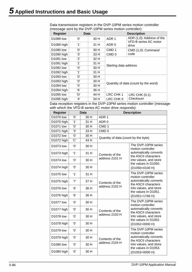
5 Applied Instructions and Basic Usage
Data transmission registers in the DVP-10PM series motion controller (message sent by the DVP-10PM series motion controller):
Register Data Description D1089 low ‘0’ 30 H ADR 1
D1089 high ‘1’ 31 H ADR 0
ADR (1,0): Address of the VFD-B series AC motor drive
D1090 low ‘0’ 30 H CMD 1 D1090 high ‘3’ 33 H CMD 0
CMD (1,0): Command code
D1091 low ‘2’ 32 H D1091 high ‘1’ 31 H D1092 low ‘0’ 30 H D1092 high ‘1’ 31 H
Starting data address
D1093 low ‘0’ 30 H D1093 high ‘0’ 30 H D1094 low ‘0’ 30 H D1094 high ‘6’ 36 H
Quantity of data (count by the word)
D1095 low ‘D’ 44 H LRC CHK 1 D1095 high ‘4’ 34 H LRC CHK 0
LRC CHK (0,1): Checksum
Data reception reigsters in the DVP-10PM series motion controller (message with which the VFD-B series AC motor drive responds):
Register Data Description D1070 low ‘0’ 30 H ADR 1 D1070 high ‘1’ 31 H ADR 0 D1071 low ‘0’ 30 H CMD 1 D1071 high ‘3’ 33 H CMD 0 D1072 low ‘0’ 30 H D1072 high ‘C’ 43 H
Quantity of data (count by the byte)
D1073 low ‘0’ 30 H
D1073 high ‘1’ 31 H
D1074 low ‘0’ 30 H
D1074 high ‘0’ 30 H
Contents of the address 2101 H
The DVP-10PM series motion controller automatically converts the ASCII characters into values, and store the values in D1050. (D1050=0100 H)
D1075 low ‘1’ 31 H
D1075 high ‘7’ 37 H
D1076 low ‘6’ 36 H
D1076 high ‘6’ 36 H
Contents of the address 2102 H
The DVP-10PM series motion controller automatically converts the ASCII characters into values, and store the values in D1051. (D1051=1766 H)
D1077 low ‘0’ 30 H
D1077 high ‘0’ 30 H
D1078 low ‘0’ 30 H
D1078 high ‘0’ 30 H
Contents of the address 2103 H
The DVP-10PM series motion controller automatically converts the ASCII characters into values, and store the values in D1052. (D1052=0000 H)
D1079 low ‘0’ 30 H
D1079 high ‘0’ 30 H
D1080 low ‘0’ 30 H
D1080 high ‘0’ 30 H
Contents of the address 2104 H
The DVP-10PM series motion controller automatically converts the ASCII characters into values, and store the values in D1053. (D1053=0000 H)
DVP-10PM Application Manual 5-86
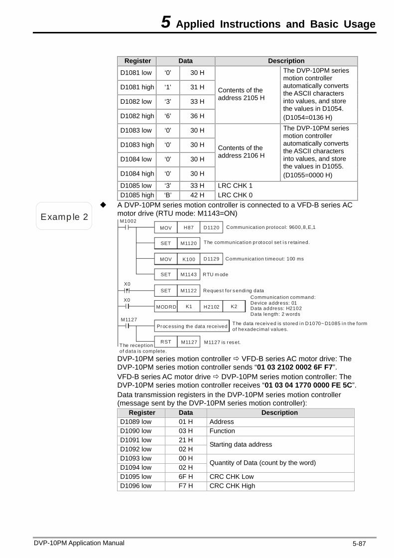
5 Applied Instructions and Basic Usage
Register Data Description
D1081 low ‘0’ 30 H
D1081 high ‘1’ 31 H
D1082 low ‘3’ 33 H
D1082 high ‘6’ 36 H
Contents of the address 2105 H
The DVP-10PM series motion controller automatically converts the ASCII characters into values, and store the values in D1054. (D1054=0136 H)
D1083 low ‘0’ 30 H
D1083 high ‘0’ 30 H
D1084 low ‘0’ 30 H
D1084 high ‘0’ 30 H
Contents of the address 2106 H
The DVP-10PM series motion controller automatically converts the ASCII characters into values, and store the values in D1055. (D1055=0000 H)
D1085 low ‘3’ 33 H LRC CHK 1 D1085 high ‘B’ 42 H LRC CHK 0
Examp le 2
A DVP-10PM series motion controller is connected to a VFD-B series AC motor drive (RTU mode: M1143=ON)
Proc essing the data received
Communication protocol: 9600,8,E,1
The communication protocol set i s retained.
Communication t imeout: 100 ms
M1127 is reset.
Reques t for s endi ng data
The data receiv ed is stored i n D1070~D1085 i n the form of hexadecimal values.
Communication command:Device address: 01Data address: H2102Data length: 2 words
The reception of data is complete.
M1002MOV H87 D1120
SET M1120
MOV K100 D1129
RST M1127
M1127
SET M1122X0
X0MODRD K1 H2102 K2
SET M1143 RTU m ode
DVP-10PM series motion controller VFD-B series AC motor drive: The DVP-10PM series motion controller sends “01 03 2102 0002 6F F7”. VFD-B series AC motor drive DVP-10PM series motion controller: The DVP-10PM series motion controller receives “01 03 04 1770 0000 FE 5C”. Data transmission registers in the DVP-10PM series motion controller (message sent by the DVP-10PM series motion controller):
Register Data Description D1089 low 01 H Address D1090 low 03 H Function D1091 low 21 H D1092 low 02 H
Starting data address
D1093 low 00 H D1094 low 02 H
Quantity of Data (count by the word)
D1095 low 6F H CRC CHK Low D1096 low F7 H CRC CHK High
DVP-10PM Application Manual 5-87
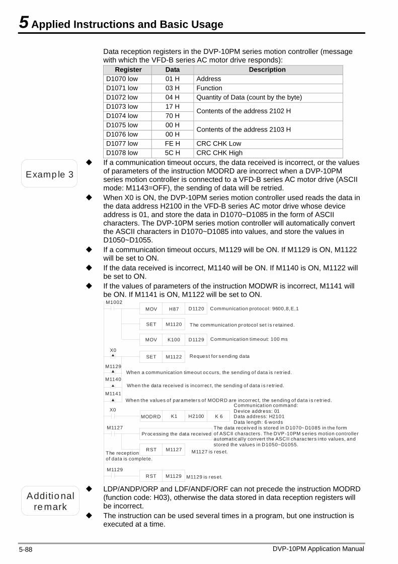
5 Applied Instructions and Basic Usage
DVP-10PM Application Manual 5-88
Data reception registers in the DVP-10PM series motion controller (message with which the VFD-B series AC motor drive responds):
Register Data Description D1070 low 01 H Address D1071 low 03 H Function D1072 low 04 H Quantity of Data (count by the byte) D1073 low 17 H D1074 low 70 H
Contents of the address 2102 H
D1075 low 00 H D1076 low 00 H
Contents of the address 2103 H
D1077 low FE H CRC CHK Low D1078 low 5C H CRC CHK High
Examp le 3
If a communication timeout occurs, the data received is incorrect, or the values of parameters of the instruction MODRD are incorrect when a DVP-10PM series motion controller is connected to a VFD-B series AC motor drive (ASCII mode: M1143=OFF), the sending of data will be retried.
When X0 is ON, the DVP-10PM series motion controller used reads the data in the data address H2100 in the VFD-B series AC motor drive whose device address is 01, and store the data in D1070~D1085 in the form of ASCII characters. The DVP-10PM series motion controller will automatically convert the ASCII characters in D1070~D1085 into values, and store the values in D1050~D1055.
If a communication timeout occurs, M1129 will be ON. If M1129 is ON, M1122 will be set to ON.
If the data received is incorrect, M1140 will be ON. If M1140 is ON, M1122 will be set to ON.
If the values of parameters of the instruction MODWR is incorrect, M1141 will be ON. If M1141 is ON, M1122 will be set to ON.
Processing the data received
Communication protocol: 9600,8,E,1
The communication protocol set i s retained.
M1127 is reset.
Reques t for sendi ng data
Communication command:Device address: 01Data address: H2101Data length: 6 words
The reception of data is complete.
M1002MOV H87 D1120
SET M1120
MOV K100 D1129
RST M1127
M1127
SET M1122X0
M1129
M1140
M1141
When a communication timeout occurs, the sending of data is retr ied.
When the data received is incorrec t, the sending of data i s retr ied.
When the values of parameters of MODRD are incorrec t, the sending of data i s retr ied.
RST M1129
MODRD K1 H2100 K 6X0
M1129
Communication timeout: 100 ms
The data received is stored in D1070~ D1085 in the form of ASCII characters . The DVP -10PM series motion controller automatical ly convert the ASCII charac ters i nto values, and stored the values in D1050~D1055.
M1129 is reset.
Additional
remark
LDP/ANDP/ORP and LDF/ANDF/ORF can not precede the instruction MODRD(function code: H03), otherwise the data stored in data reception registers will be incorrect.
The instruction can be used several times in a program, but one instruction is executed at a time.
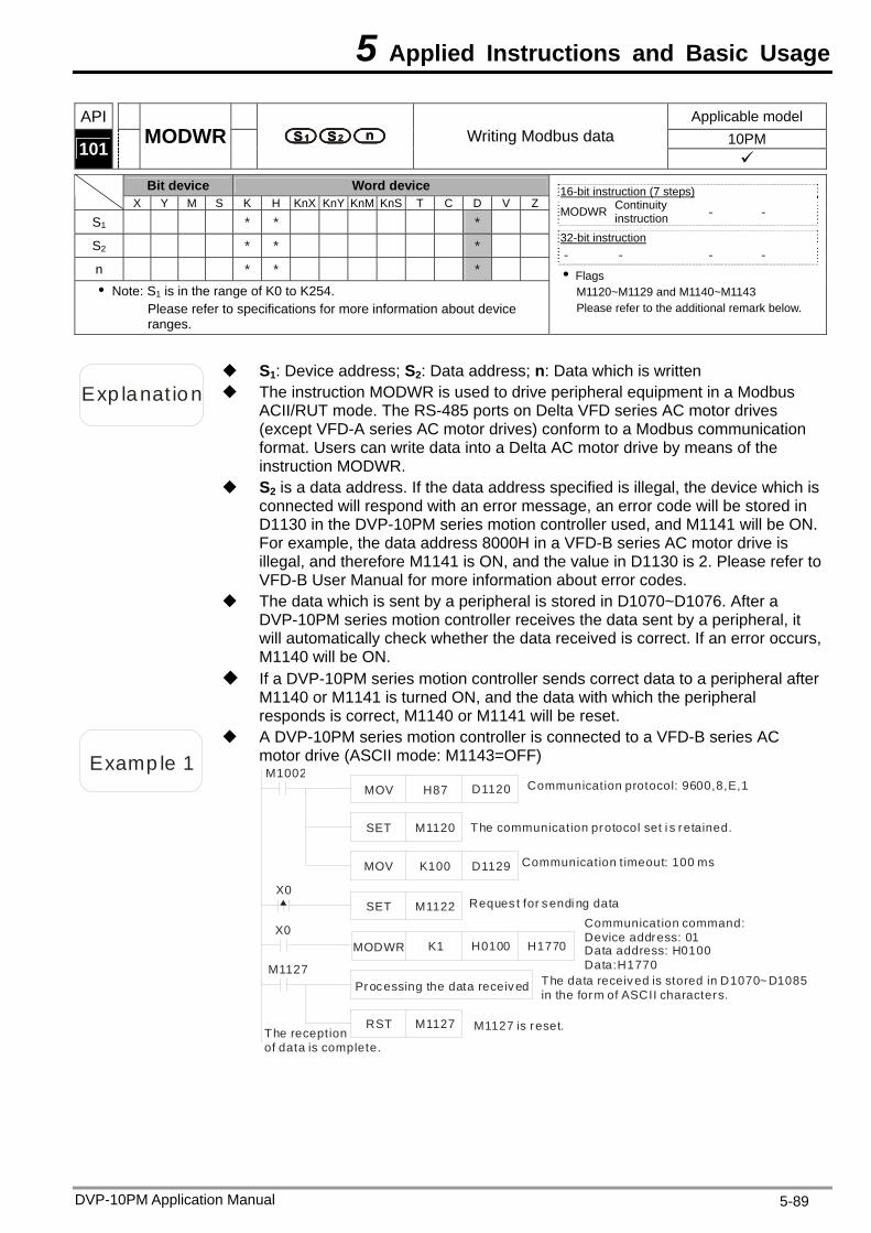
5 Applied Instructions and Basic Usage
API Applicable model 10PM 101 MODWR Writing Modbus data
Bit device Word device X Y M S K H KnX KnY KnM KnS T C D V Z
S1 * * *
S2 * * *
n * * * Note: S1 is in the range of K0 to K254.
Please refer to specifications for more information about device ranges.
16-bit instruction (7 steps) MODWR Continuity
instruction - -
32-bit instruction - - - -
Flags M1120~M1129 and M1140~M1143 Please refer to the additional remark below.
Exp lanat ion The instruction MODWR is used to drive peripheral equipment in a Modbus ACII/RUT mode. The RS-485 ports on Delta VFD series AC motor drives (except VFD-A series AC motor drives) conform to a Modbus communication format. Users can write data into a Delta AC motor drive by means of the instruction MODWR.
S1: Device address; S2: Data address; n: Data which is written
S2 is a data address. If the data address specified is illegal, the device which is connected will respond with an error message, an error code will be stored in D1130 in the DVP-10PM series motion controller used, and M1141 will be ON. For example, the data address 8000H in a VFD-B series AC motor drive is illegal, and therefore M1141 is ON, and the value in D1130 is 2. Please refer to VFD-B User Manual for more information about error codes.
The data which is sent by a peripheral is stored in D1070~D1076. After a DVP-10PM series motion controller receives the data sent by a peripheral, it will automatically check whether the data received is correct. If an error occurs, M1140 will be ON.
If a DVP-10PM series motion controller sends correct data to a peripheral after M1140 or M1141 is turned ON, and the data with which the peripheral responds is correct, M1140 or M1141 will be reset.
Examp le 1
A DVP-10PM series motion controller is connected to a VFD-B series AC motor drive (ASCII mode: M1143=OFF)
Processing the data receiv ed
Communication protocol: 9600,8,E,1
The communication protocol set i s retained.
Communication t imeout: 100 ms
M1127 is reset.
Reques t for s endi ng data
The data received is stored in D1070~ D1085 in the form of ASCII characters.
Communication command:Device address: 01Data address: H0100Data:H1770
The reception of data is complete.
M1002MOV H87 D1120
SET M1120
MOV K100 D1129
RST M1127
M1127
SET M1122X0
MODWR K1 H0100 H1770X0
DVP-10PM Application Manual 5-89
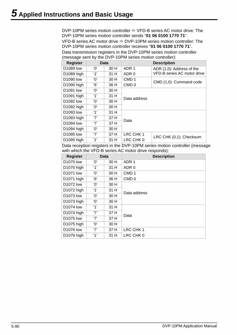
5 Applied Instructions and Basic Usage
DVP-10PM series motion controller VFD-B series AC motor drive: The DVP-10PM series motion controller sends “01 06 0100 1770 71”. VFD-B series AC motor drive DVP-10PM series motion controller: The DVP-10PM series motion controller receives “01 06 0100 1770 71”. Data transmission registers in the DVP-10PM series motion controller (message sent by the DVP-10PM series motion controller):
Register Data Description D1089 low ‘0’ 30 H ADR 1 D1089 high ‘1’ 31 H ADR 0
ADR (1,0): Address of the VFD-B series AC motor drive
D1090 low ‘0’ 30 H CMD 1 D1090 high ‘6’ 36 H CMD 0
CMD (1,0): Command code
D1091 low ‘0’ 30 H D1091 high ‘1’ 31 H D1092 low ‘0’ 30 H D1092 high ‘0’ 30 H
Data address
D1093 low ‘1’ 31 H D1093 high ‘7’ 37 H D1094 low ‘7’ 37 H D1094 high ‘0’ 30 H
Data
D1095 low ‘7’ 37 H LRC CHK 1 D1095 high ‘1’ 31 H LRC CHK 0
LRC CHK (0,1): Checksum
Data reception reigsters in the DVP-10PM series motion controller (message with which the VFD-B series AC motor drive responds):
Register Data Description D1070 low ‘0’ 30 H ADR 1 D1070 high ‘1’ 31 H ADR 0 D1071 low ‘0’ 30 H CMD 1 D1071 high ‘6’ 36 H CMD 0 D1072 low ‘0’ 30 H D1072 high ‘1’ 31 H D1073 low ‘0’ 30 H D1073 high ‘0’ 30 H
Data address
D1074 low ‘1’ 31 H D1074 high ‘7’ 37 H D1075 low ‘7’ 37 H D1075 high ‘0’ 30 H
Data
D1076 low ‘7’ 37 H LRC CHK 1 D1076 high ‘1’ 31 H LRC CHK 0
DVP-10PM Application Manual 5-90
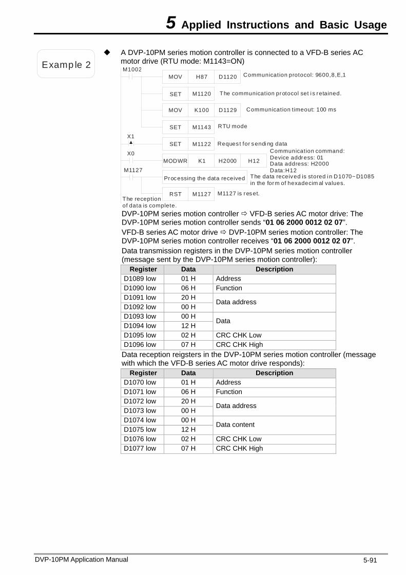
5 Applied Instructions and Basic Usage
Examp le 2
A DVP-10PM series motion controller is connected to a VFD-B series AC motor drive (RTU mode: M1143=ON)
Processing the data received
Communication protocol: 9600,8,E,1
The communication protocol set i s retained.
Communication t imeout: 100 ms
M1127 is res et.
Reques t for sendi ng data
The data received is stored i n D1070~ D1085 in the form of hexadecim al values.
Communication command:Device address: 01Data address: H2000Data:H12
The reception of data is complete.
M1002MOV H87 D1120
SET M1120
SET M1143
MOV K100 D1129
RST M1127
M1127
X0MODWR K1 H2000 H12
SET M1122X1
RTU mode
DVP-10PM series motion controller VFD-B series AC motor drive: The DVP-10PM series motion controller sends “01 06 2000 0012 02 07”. VFD-B series AC motor drive DVP-10PM series motion controller: The DVP-10PM series motion controller receives “01 06 2000 0012 02 07”. Data transmission registers in the DVP-10PM series motion controller (message sent by the DVP-10PM series motion controller):
Register Data Description D1089 low 01 H Address D1090 low 06 H Function D1091 low 20 H D1092 low 00 H
Data address
D1093 low 00 H D1094 low 12 H
Data
D1095 low 02 H CRC CHK Low D1096 low 07 H CRC CHK High
Data reception reigsters in the DVP-10PM series motion controller (message with which the VFD-B series AC motor drive responds):
Register Data Description D1070 low 01 H Address D1071 low 06 H Function D1072 low 20 H D1073 low 00 H
Data address
D1074 low 00 H D1075 low 12 H
Data content
D1076 low 02 H CRC CHK Low D1077 low 07 H CRC CHK High
DVP-10PM Application Manual 5-91
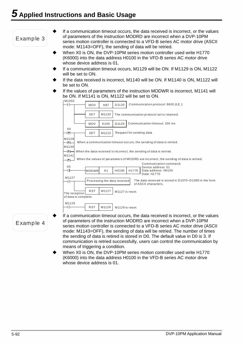
5 Applied Instructions and Basic Usage
Examp le 3
If a communication timeout occurs, the data received is incorrect, or the values of parameters of the instruction MODRD are incorrect when a DVP-10PM series motion controller is connected to a VFD-B series AC motor drive (ASCII mode: M1143=OFF), the sending of data will be retried.
When X0 is ON, the DVP-10PM series motion controller used write H1770 (K6000) into the data address H0100 in the VFD-B series AC motor drive whose device address is 01.
If a communication timeout occurs, M1129 will be ON. If M1129 is ON, M1122 will be set to ON.
If the data received is incorrect, M1140 will be ON. If M1140 is ON, M1122 will be set to ON.
If the values of parameters of the instruction MODWR is incorrect, M1141 will be ON. If M1141 is ON, M1122 will be set to ON.
Processing the data received
Communication protocol: 9600,8,E ,1
The communication protocol set is retained.
M1127 is reset.
Reques t for sending data
Communi cation command:Device address: 01Data address: H0100Data: H1770
The reception of data is complete.
When a communicat ion t imeout occ urs, the sendi ng of data is retried.
When the data received is i ncorrec t, the sending of data is retri ed.
When the values of parameters of MODRD are inc orrect, the sendi ng of data is retried.
Communi cat ion t imeout: 100 ms
The data received is stored in D1070~D1085 in the form of ASCII characters.
M1129 is reset.
M1002MOV H87 D1120
SET M1120
MOV K100 D1129
RST M1127
M1129
MODWR K1 H0100 H1770X0
SET M1122X0
M1129
M1140
M1141
RST M1129
M1127
Examp le 4
If a communication timeout occurs, the data received is incorrect, or the values of parameters of the instruction MODRD are incorrect when a DVP-10PM series motion controller is connected to a VFD-B series AC motor drive (ASCII mode: M1143=OFF), the sending of data will be retried. The number of times the sending of data is retired is stored in D0. The default value in D0 is 3. If communication is retried successfully, users can control the communication by means of triggering a condition.
When X0 is ON, the DVP-10PM series motion controller used write H1770 (K6000) into the data address H0100 in the VFD-B series AC motor drive whose device address is 01.
DVP-10PM Application Manual 5-92
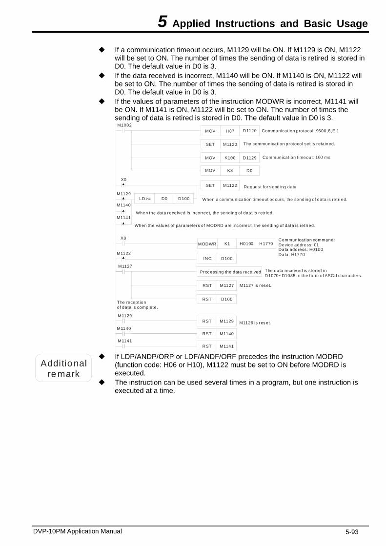
5 Applied Instructions and Basic Usage
DVP-10PM Application Manual 5-93
If a communication timeout occurs, M1129 will be ON. If M1129 is ON, M1122 will be set to ON. The number of times the sending of data is retired is stored in D0. The default value in D0 is 3.
If the data received is incorrect, M1140 will be ON. If M1140 is ON, M1122 will be set to ON. The number of times the sending of data is retired is stored in D0. The default value in D0 is 3.
If the values of parameters of the instruction MODWR is incorrect, M1141 will be ON. If M1141 is ON, M1122 will be set to ON. The number of times the sending of data is retired is stored in D0. The default value in D0 is 3.
Processing the data received
Communication protocol: 9600,8,E,1
The communication protocol set is retained.
M1127 is res et.
Reques t for s endi ng data
Communication command:Device address: 01Data address: H0100Data: H1770
The reception of data is complete.
When a communication t imeout occurs, the sending of data is retri ed.
When the data received is incorrec t, the sending of data is retr ied.
When the values of parameters of MODRD are i nc orrec t, the sending of data is retri ed.
Communication t imeout: 100 ms
The data receiv ed is stored i n D1070~ D1085 i n the form of ASCII characters.
M1129 is res et.
M1002MOV H87 D1120
SET M1120
SET M1122
MOV K100 D1129
RST M1127
M1127
X0
MODWR K1 H0100 H1770X0
M1129
M1140
M1141
RST
M1129
MOV K3 D0
LD>= D0 D100
M1122INC D100
RST
D100
M1129
M1140RSTM1140
M1141RSTM1141
Additional
remark
If LDP/ANDP/ORP or LDF/ANDF/ORF precedes the instruction MODRD (function code: H06 or H10), M1122 must be set to ON before MODRD is executed.
The instruction can be used several times in a program, but one instruction is executed at a time.
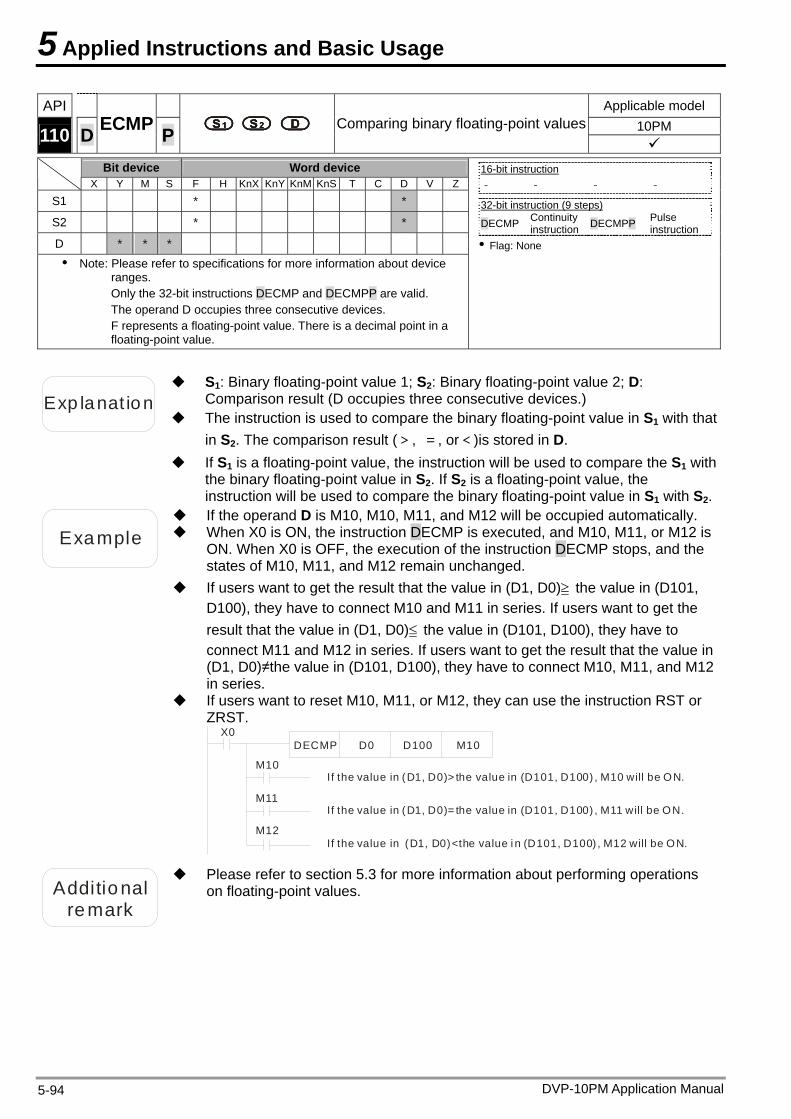
5 Applied Instructions and Basic Usage
API Applicable model 10PM 110 D ECMP P Comparing binary floating-point values
Bit device Word device X Y M S F H KnX KnY KnM KnS T C D V Z
S1 * *
S2 * *
D * * * Note: Please refer to specifications for more information about device
ranges. Only the 32-bit instructions DECMP and DECMPP are valid. The operand D occupies three consecutive devices. F represents a floating-point value. There is a decimal point in a floating-point value.
16-bit instruction - - - -
32-bit instruction (9 steps) DECMP Continuity
instruction DECMPP Pulse instruction
Flag: None
Exp lanat ion
S1: Binary floating-point value 1; S2: Binary floating-point value 2; D: Comparison result (D occupies three consecutive devices.)
The instruction is used to compare the binary floating-point value in S1 with that in S2. The comparison result (>, =, or<)is stored in D.
If S1 is a floating-point value, the instruction will be used to compare the S1 with the binary floating-point value in S2. If S2 is a floating-point value, the instruction will be used to compare the binary floating-point value in S1 with S2.
Example
If the operand D is M10, M10, M11, and M12 will be occupied automatically. When X0 is ON, the instruction DECMP is executed, and M10, M11, or M12 is
ON. When X0 is OFF, the execution of the instruction DECMP stops, and the states of M10, M11, and M12 remain unchanged.
If users want to get the result that the value in (D1, D0)≧ the value in (D101, D100), they have to connect M10 and M11 in series. If users want to get the result that the value in (D1, D0)≦ the value in (D101, D100), they have to connect M11 and M12 in series. If users want to get the result that the value in (D1, D0)≠the value in (D101, D100), they have to connect M10, M11, and M12 in series.
If users want to reset M10, M11, or M12, they can use the instruction RST or ZRST.
X0DECMP D0 D100 M10
M10
M11
M12
If the value in (D1, D0)> the value in (D101, D100) , M10 will be ON.
If the value in (D1, D0)= the value in (D101, D100) , M11 will be ON.
If the value in (D1, D0)<the value i n (D101, D100) , M12 will be ON.
Additional remark
Please refer to section 5.3 for more information about performing operations on floating-point values.
DVP-10PM Application Manual 5-94
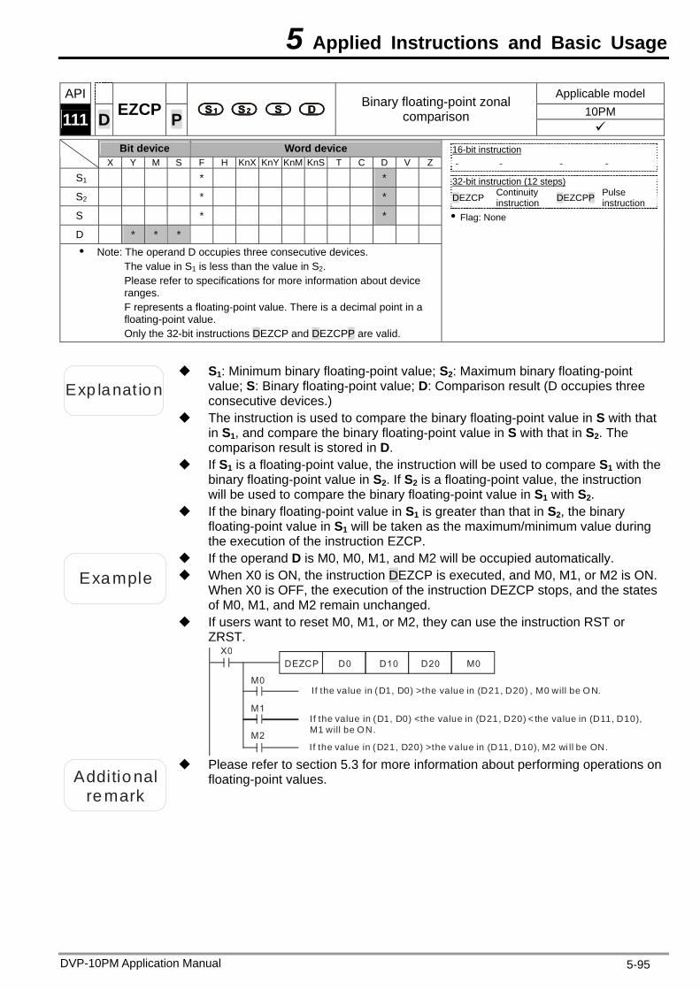
5 Applied Instructions and Basic Usage
DVP-10PM Application Manual 5-95
API Applicable model 10PM 111 D EZCP P
Binary floating-point zonal comparison
Bit device Word device
X Y M S F H KnX KnY KnM KnS T C D V Z
S1 * *
S2 * *
S * *
D * * * Note: The operand D occupies three consecutive devices.
The value in S1 is less than the value in S2. Please refer to specifications for more information about device ranges. F represents a floating-point value. There is a decimal point in a floating-point value. Only the 32-bit instructions DEZCP and DEZCPP are valid.
16-bit instruction - - - -
32-bit instruction (12 steps) DEZCP Continuity
instruction DEZCPP Pulse instruction
Flag: None
Exp lanat ion
S1: Minimum binary floating-point value; S2: Maximum binary floating-point value; S: Binary floating-point value; D: Comparison result (D occupies three consecutive devices.)
The instruction is used to compare the binary floating-point value in S with that in S1, and compare the binary floating-point value in S with that in S2. The comparison result is stored in D.
If S1 is a floating-point value, the instruction will be used to compare S1 with the binary floating-point value in S2. If S2 is a floating-point value, the instruction will be used to compare the binary floating-point value in S1 with S2.
If the binary floating-point value in S1 is greater than that in S2, the binary floating-point value in S1 will be taken as the maximum/minimum value during the execution of the instruction EZCP.
Example
If the operand D is M0, M0, M1, and M2 will be occupied automatically. When X0 is ON, the instruction DEZCP is executed, and M0, M1, or M2 is ON.
When X0 is OFF, the execution of the instruction DEZCP stops, and the states of M0, M1, and M2 remain unchanged.
If users want to reset M0, M1, or M2, they can use the instruction RST or ZRST.
X0DEZCP D0 D10 D20
M0
M1
M2
If the value in (D1, D0) >the value in (D21, D20) , M0 will be ON.
If the value in (D1, D0) <the value in (D21, D20) < the value in (D11, D10), M1 will be ON.
If the value in (D21, D20) >the value in (D11, D10), M2 wi ll be ON.
M0
Additional
remark
Please refer to section 5.3 for more information about performing operations on floating-point values.
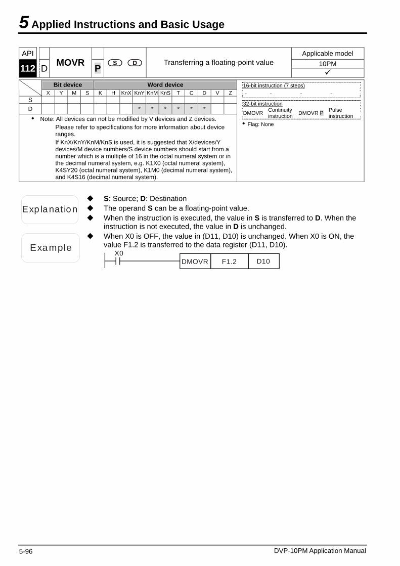
5 Applied Instructions and Basic Usage
API Applicable model 10PM 112 D MOVR P Transferring a floating-point value
Bit device Word device X Y M S K H KnX KnY KnM KnS T C D V Z
S D * * * * * * Note: All devices can not be modified by V devices and Z devices.
Please refer to specifications for more information about device ranges. If KnX/KnY/KnM/KnS is used, it is suggested that X/devices/Y devices/M device numbers/S device numbers should start from a number which is a multiple of 16 in the octal numeral system or in the decimal numeral system, e.g. K1X0 (octal numeral system), K4SY20 (octal numeral system), K1M0 (decimal numeral system), and K4S16 (decimal numeral system).
16-bit instruction (7 steps) - - - -
32-bit instruction
DMOVR Continuity instruction DMOVR P Pulse
instruction Flag: None
Exp lanat ion The operand S can be a floating-point value.
S: Source; D: Destination
When the instruction is executed, the value in S is transferred to D. When the instruction is not executed, the value in D is unchanged.
Example
When X0 is OFF, the value in (D11, D10) is unchanged. When X0 is ON, the value F1.2 is transferred to the data register (D11, D10).
X0DMOVR F1.2 D10
DVP-10PM Application Manual 5-96
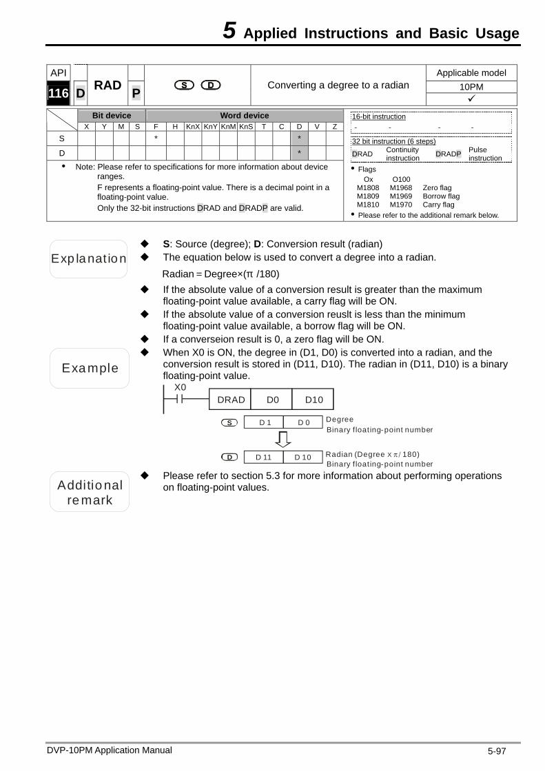
5 Applied Instructions and Basic Usage
DVP-10PM Application Manual 5-97
API Applicable model 10PM 116 D RAD P Converting a degree to a radian
Bit device Word device X Y M S F H KnX KnY KnM KnS T C D V Z
S * *
D * Note: Please refer to specifications for more information about device
ranges. F represents a floating-point value. There is a decimal point in a floating-point value. Only the 32-bit instructions DRAD and DRADP are valid.
16-bit instruction - - - -
32 bit instruction (6 steps)
DRAD Continuity instruction DRADP Pulse
instruction Flags
Ox O100 M1808 M1968 Zero flag M1809 M1969 Borrow flag M1810 M1970 Carry flag Please refer to the additional remark below.
Exp lanat ion The equation below is used to convert a degree into a radian.
S: Source (degree); D: Conversion result (radian)
Radian=Degree×(π /180) If the absolute value of a conversion result is greater than the maximum
floating-point value available, a carry flag will be ON. If the absolute value of a conversion reuslt is less than the minimum
floating-point value available, a borrow flag will be ON. If a converseion result is 0, a zero flag will be ON.
Example
When X0 is ON, the degree in (D1, D0) is converted into a radian, and the conversion result is stored in (D11, D10). The radian in (D11, D10) is a binary floating-point value.
X0DRAD D0 D10
D 1 D 0S
D D 11 D 10
DegreeBinary f loating-point number
Binary f loating-point numberRadian (Degree 180)X /
Additional
remark
Please refer to section 5.3 for more information about performing operations on floating-point values.
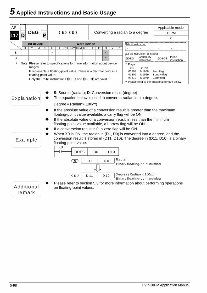
5 Applied Instructions and Basic Usage
DVP-10PM Application Manual 5-98
API Applicable model 10PM 117 D DEG P Converting a radian to a degree
Bit device Word device X Y M S F H KnX KnY KnM KnS T C D V Z
S * *
D * Note: Please refer to specifications for more information about device
ranges. F represents a floating-point value. There is a decimal point in a floating-point value. Only the 32-bit instructions DDEG and DDEGP are valid.
16-bit instruction - - - -
32-bit instruction (6 steps)
DDEG Continuity instruction DDEGP Pulse
instruction Flags
Ox O100 M1808 M1968 Zero flag M1809 M1969 Borrow flag M1810 M1970 Carry flag Please refer to the additional remark below.
Exp lanat ion
S: Source (radian); D: Conversion result (degree) The equation below is used to convert a radian into a degree.
Degree=Radian×(180/π) If the absolute value of a conversion result is greater than the maximum
floating-point value available, a carry flag will be ON. If the absolute value of a conversion reuslt is less than the minimum
floating-point value available, a borrow flag will be ON. If a converseion result is 0, a zero flag will be ON.
Example
When X0 is ON, the radian in (D1, D0) is converted into a degree, and the conversion result is stored in (D11, D10). The degree in (D11, D10) is a binary floating-point value.
X0DDEG D0 D10
D 1 D 0S
D D 11 D 10
RadianBinary f loating-point number
Binary f loating-point numberDegree (Radian 180/p)X
Additional
remark
Please refer to section 5.3 for more information about performing operations on floating-point values.
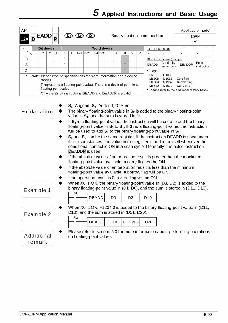
5 Applied Instructions and Basic Usage
API Applicable model 10PM 120 D EADD P Binary floating-point addition
Bit device Word device X Y M S F H KnX KnY KnM KnS T C D V Z
S1 * *
S2 * *
D * Note: Please refer to specifications for more information about device
ranges. F represents a floating-point value. There is a decimal point in a floating-point value. Only the 32-bit instructions DEADD and DEADDP are valid.
16-bit instruction - - - -
32-bit instruction (9 steps) DEADD Continuity
instruction DEADDP Pulse instruction
Flags Ox O100 M1808 M1968 Zero flag M1809 M1969 Borrow flag M1810 M1970 Carry flag Please refer to the additional remark below.
Exp lanat ion The binary floating-point value in S2 is added to the binary floating-point value in S1, and the sum is stored in D.
S1: Augend; S2: Addend; D: Sum
If S1 is a floating-point value, the instruction will be used to add the binary floating-point value in S2 to S1. If S2 is a floating-point value, the instruction will be used to add S2 to the binary floating-point value in S1.
S1 and S2 can be the same register. If the instruction DEADD is used under the circumstances, the value in the register is added to itself whenever the conditional contact is ON in a scan cycle. Generally, the pulse instruction DEADDP is used.
If the absolute value of an oepration result is greater than the maximum floating-point value available, a carry flag will be ON.
If the absolute value of an oepration reuslt is less than the minimum floating-point value available, a borrow flag will be ON.
If an operation result is 0, a zero flag will be ON.
Examp le 1
When X0 is ON, the binary floating-point value in (D3, D2) is added to the binary floating-point value in (D1, D0), and the sum is stored in (D11, D10).
X0DEADD D0 D2 D10
Examp le 2
When X0 is ON, F1234.0 is added to the binary floating-point value in (D11, D10), and the sum is stored in (D21, D20).
X2DEADD D10 F1234.0 D20
Additional remark
Please refer to section 5.3 for more information about performing operations on floating-point values.
DVP-10PM Application Manual 5-99
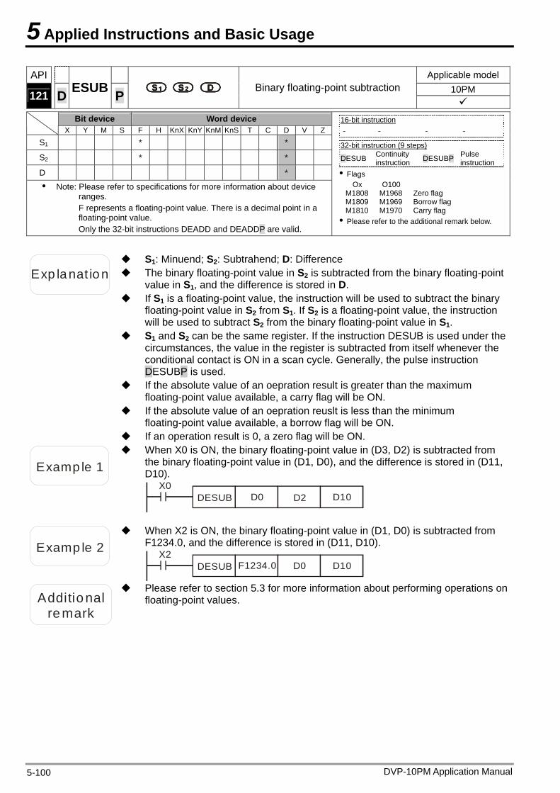
5 Applied Instructions and Basic Usage
DVP-10PM Application Manual 5-100
API Applicable model 10PM 121 D ESUB P Binary floating-point subtraction
Bit device Word device X Y M S F H KnX KnY KnM KnS T C D V Z
S1 * *
S2 * *
D * Note: Please refer to specifications for more information about device
ranges. F represents a floating-point value. There is a decimal point in a floating-point value. Only the 32-bit instructions DEADD and DEADDP are valid.
16-bit instruction - - - -
32-bit instruction (9 steps) DESUB Continuity
instruction DESUBP Pulse instruction
Flags Ox O100
M1808 M1968 Zero flag M1809 M1969 Borrow flag M1810 M1970 Carry flag Please refer to the additional remark below.
Exp lanat ion The binary floating-point value in S2 is subtracted from the binary floating-point value in S1, and the difference is stored in D.
S1: Minuend; S2: Subtrahend; D: Difference
If S1 is a floating-point value, the instruction will be used to subtract the binary floating-point value in S2 from S1. If S2 is a floating-point value, the instruction will be used to subtract S2 from the binary floating-point value in S1.
S1 and S2 can be the same register. If the instruction DESUB is used under the circumstances, the value in the register is subtracted from itself whenever the conditional contact is ON in a scan cycle. Generally, the pulse instruction DESUBP is used.
If the absolute value of an oepration result is greater than the maximum floating-point value available, a carry flag will be ON.
If the absolute value of an oepration reuslt is less than the minimum floating-point value available, a borrow flag will be ON.
If an operation result is 0, a zero flag will be ON.
Examp le 1
When X0 is ON, the binary floating-point value in (D3, D2) is subtracted from the binary floating-point value in (D1, D0), and the difference is stored in (D11, D10).
X0DESUB D0 D2 D10
Examp le 2
When X2 is ON, the binary floating-point value in (D1, D0) is subtracted from F1234.0, and the difference is stored in (D11, D10).
X2DESUB D0F1234.0 D10
Additional
remark
Please refer to section 5.3 for more information about performing operations onfloating-point values.
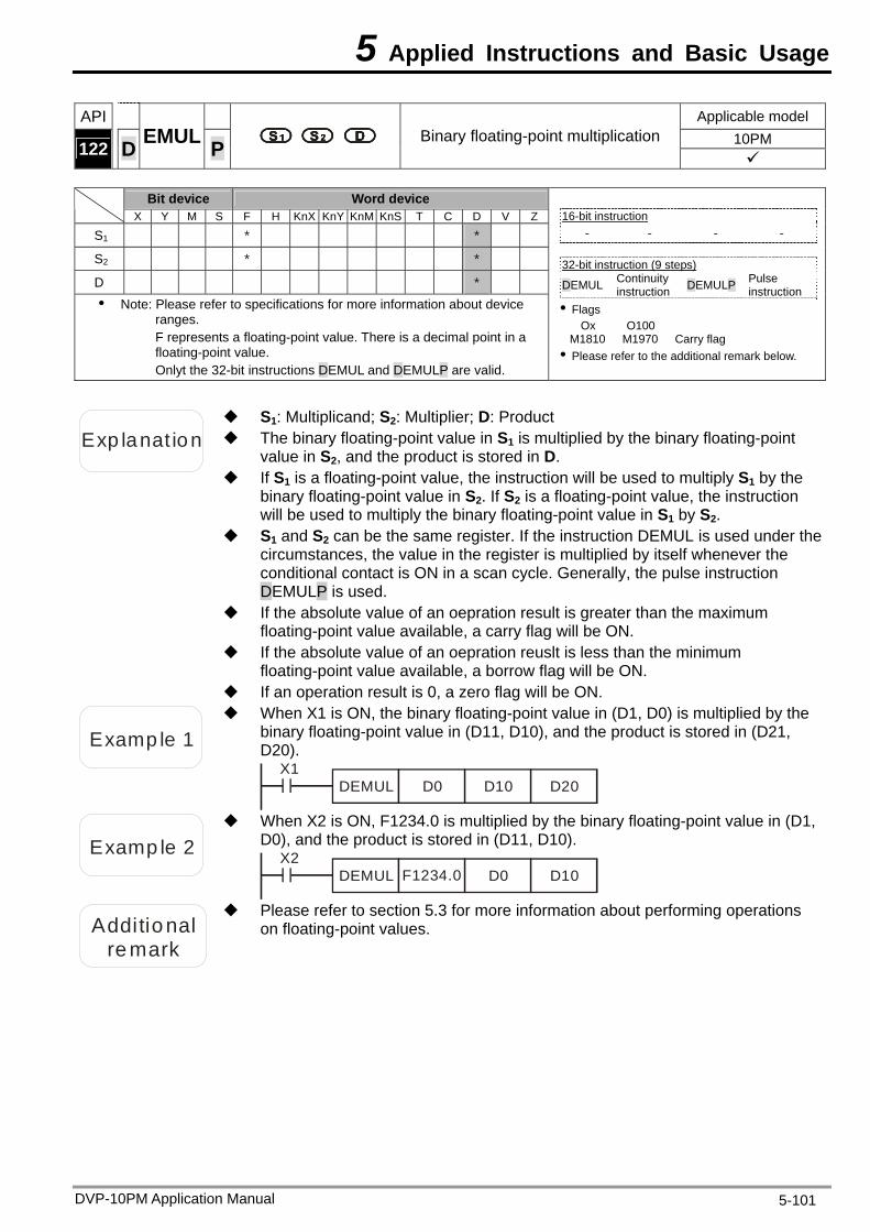
5 Applied Instructions and Basic Usage
API Applicable model 10PM 122 D EMUL P Binary floating-point multiplication
Bit device Word device
X Y M S F H KnX KnY KnM KnS T C D V Z
S1 * *
S2 * *
D * Note: Please refer to specifications for more information about device
ranges. F represents a floating-point value. There is a decimal point in a floating-point value. Onlyt the 32-bit instructions DEMUL and DEMULP are valid.
16-bit instruction
- - - -
32-bit instruction (9 steps) DEMUL Continuity
instruction DEMULP Pulse instruction
Flags Ox O100
M1810 M1970 Carry flag Please refer to the additional remark below.
Exp lanat ion The binary floating-point value in S1 is multiplied by the binary floating-point value in S2, and the product is stored in D.
S1: Multiplicand; S2: Multiplier; D: Product
If S1 is a floating-point value, the instruction will be used to multiply S1 by the binary floating-point value in S2. If S2 is a floating-point value, the instruction will be used to multiply the binary floating-point value in S1 by S2.
S1 and S2 can be the same register. If the instruction DEMUL is used under the circumstances, the value in the register is multiplied by itself whenever the conditional contact is ON in a scan cycle. Generally, the pulse instruction DEMULP is used.
If the absolute value of an oepration result is greater than the maximum floating-point value available, a carry flag will be ON.
If the absolute value of an oepration reuslt is less than the minimum floating-point value available, a borrow flag will be ON.
If an operation result is 0, a zero flag will be ON.
Examp le 1
When X1 is ON, the binary floating-point value in (D1, D0) is multiplied by the binary floating-point value in (D11, D10), and the product is stored in (D21, D20).
X1DEMUL D0 D10 D20
Examp le 2
When X2 is ON, F1234.0 is multiplied by the binary floating-point value in (D1, D0), and the product is stored in (D11, D10).
X2DEMUL D0F1234.0 D10
Additional remark
Please refer to section 5.3 for more information about performing operations on floating-point values.
DVP-10PM Application Manual 5-101
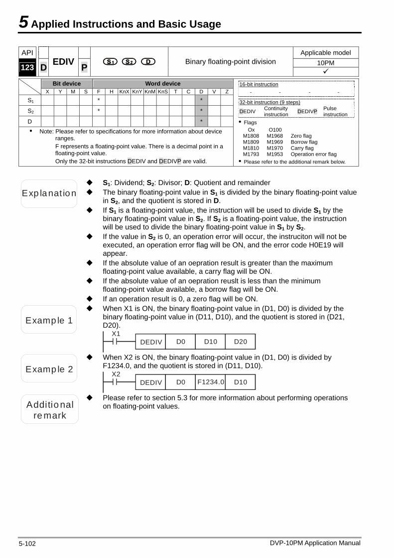
5 Applied Instructions and Basic Usage
API Applicable model 10PM 123 D EDIV P Binary floating-point division
Bit device Word device X Y M S F H KnX KnY KnM KnS T C D V Z
S1 * *
S2 * *
D * Note: Please refer to specifications for more information about device
ranges. F represents a floating-point value. There is a decimal point in a floating-point value. Only the 32-bit instructions DEDIV and DEDIVP are valid.
16-bit instruction
- - - -
32-bit instruction (9 steps) DEDIV Continuity
instruction DEDIVP Pulse instruction
Flags Ox O100
M1808 M1968 Zero flag M1809 M1969 Borrow flag M1810 M1970 Carry flag M1793 M1953 Operation error flag Please refer to the additional remark below.
Exp lanat ion The binary floating-point value in S1 is divided by the binary floating-point value in S2, and the quotient is stored in D.
S1: Dividend; S2: Divisor; D: Quotient and remainder
If S1 is a floating-point value, the instruction will be used to divide S1 by the binary floating-point value in S2. If S2 is a floating-point value, the instruction will be used to divide the binary floating-point value in S1 by S2.
If the value in S2 is 0, an operation error will occur, the instruciton will not be executed, an operation error flag will be ON, and the error code H0E19 will appear.
If the absolute value of an oepration result is greater than the maximum floating-point value available, a carry flag will be ON.
If the absolute value of an oepration reuslt is less than the minimum floating-point value available, a borrow flag will be ON.
If an operation result is 0, a zero flag will be ON.
Examp le 1
When X1 is ON, the binary floating-point value in (D1, D0) is divided by the binary floating-point value in (D11, D10), and the quotient is stored in (D21, D20).
X1DEDIV D0 D10 D20
Examp le 2
When X2 is ON, the binary floating-point value in (D1, D0) is divided by F1234.0, and the quotient is stored in (D11, D10).
X2DEDIV D0 F1234.0 D10
Additional remark
Please refer to section 5.3 for more information about performing operations on floating-point values.
DVP-10PM Application Manual 5-102
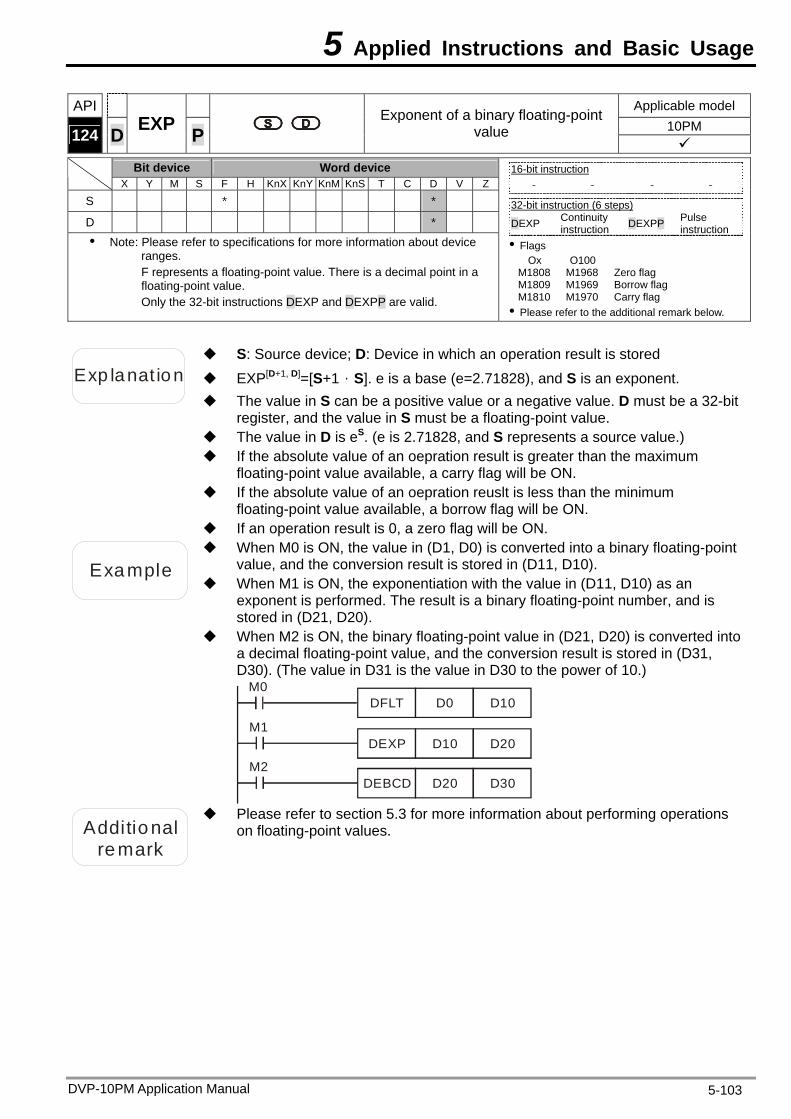
5 Applied Instructions and Basic Usage
DVP-10PM Application Manual 5-103
API Applicable model 10PM 124 D EXP P
Exponent of a binary floating-point value
Bit device Word device
X Y M S F H KnX KnY KnM KnS T C D V Z
S * *
D * Note: Please refer to specifications for more information about device
ranges. F represents a floating-point value. There is a decimal point in a floating-point value. Only the 32-bit instructions DEXP and DEXPP are valid.
16-bit instruction
- - - -
32-bit instruction (6 steps) DEXP Continuity
instruction DEXPP Pulse instruction
Flags Ox O100
M1808 M1968 Zero flag M1809 M1969 Borrow flag M1810 M1970 Carry flag Please refer to the additional remark below.
Exp lanat ion EXP[D+1, D]=[S+1,S]. e is a base (e=2.71828), and S is an exponent.
S: Source device; D: Device in which an operation result is stored
The value in S can be a positive value or a negative value. D must be a 32-bit register, and the value in S must be a floating-point value.
The value in D is eS. (e is 2.71828, and S represents a source value.) If the absolute value of an oepration result is greater than the maximum
floating-point value available, a carry flag will be ON. If the absolute value of an oepration reuslt is less than the minimum
floating-point value available, a borrow flag will be ON. If an operation result is 0, a zero flag will be ON.
Example
When M0 is ON, the value in (D1, D0) is converted into a binary floating-point value, and the conversion result is stored in (D11, D10).
When M1 is ON, the exponentiation with the value in (D11, D10) as an exponent is performed. The result is a binary floating-point number, and is stored in (D21, D20).
When M2 is ON, the binary floating-point value in (D21, D20) is converted into a decimal floating-point value, and the conversion result is stored in (D31, D30). (The value in D31 is the value in D30 to the power of 10.)
M0DFLT D0 D10
M1DEXP D10 D20
M2DEBCD D20 D30
Additional
remark
Please refer to section 5.3 for more information about performing operations on floating-point values.
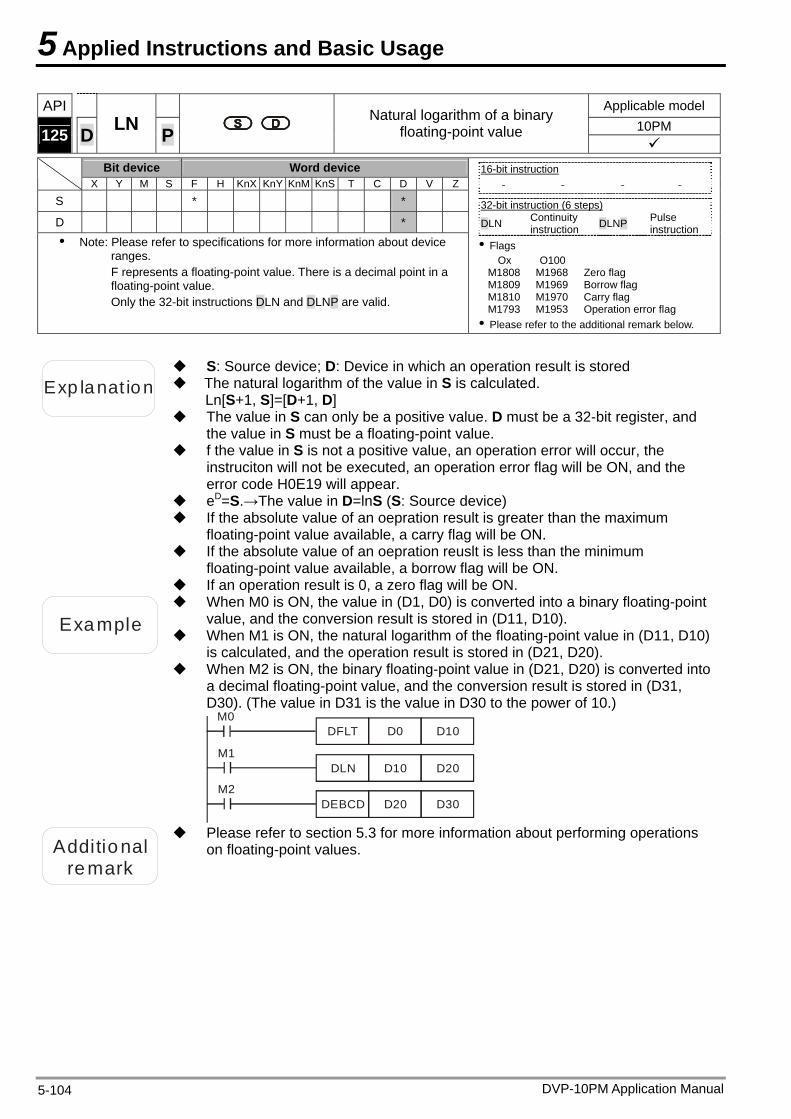
5 Applied Instructions and Basic Usage
API Applicable model 10PM 125 D LN
Natural logarithm of a binary floating-point value P
Bit device Word device X Y M S F H KnX KnY KnM KnS T C D V Z
S * *
D * Note: Please refer to specifications for more information about device
ranges. F represents a floating-point value. There is a decimal point in a floating-point value. Only the 32-bit instructions DLN and DLNP are valid.
16-bit instruction
- - - -
32-bit instruction (6 steps) DLN Continuity
instruction DLNP Pulse instruction
Flags Ox O100
M1808 M1968 Zero flag M1809 M1969 Borrow flag M1810 M1970 Carry flag M1793 M1953 Operation error flag Please refer to the additional remark below.
Exp lanat ion The natural logarithm of the value in S is calculated.
S: Source device; D: Device in which an operation result is stored
Ln[S+1, S]=[D+1, D] The value in S can only be a positive value. D must be a 32-bit register, and
the value in S must be a floating-point value. f the value in S is not a positive value, an operation error will occur, the
instruciton will not be executed, an operation error flag will be ON, and the error code H0E19 will appear.
eD=S.→The value in D=lnS (S: Source device) If the absolute value of an oepration result is greater than the maximum
floating-point value available, a carry flag will be ON. If the absolute value of an oepration reuslt is less than the minimum
floating-point value available, a borrow flag will be ON. If an operation result is 0, a zero flag will be ON.
Example When M1 is ON, the natural logarithm of the floating-point value in (D11, D10)
is calculated, and the operation result is stored in (D21, D20).
When M0 is ON, the value in (D1, D0) is converted into a binary floating-point value, and the conversion result is stored in (D11, D10).
When M2 is ON, the binary floating-point value in (D21, D20) is converted into a decimal floating-point value, and the conversion result is stored in (D31, D30). (The value in D31 is the value in D30 to the power of 10.)
M0DFLT D0 D10
M1DLN D10 D20
M2DEBCD D20 D30
Additional remark
Please refer to section 5.3 for more information about performing operations on floating-point values.
DVP-10PM Application Manual 5-104
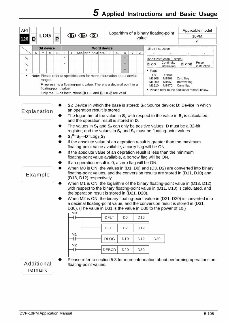
5 Applied Instructions and Basic Usage
DVP-10PM Application Manual 5-105
API Applicable model 10PM 126 D LOG P
Logarithm of a binary floating-point value
Bit device Word device
X Y M S F H KnX KnY KnM KnS T C D V Z
S1 * *
S2 * *
D * Note: Please refer to specifications for more information about device
ranges. F represents a floating-point value. There is a decimal point in a floating-point value. Only the 32-bit instructions DLOG and DLOGP are valid.
16-bit instruction
- - - -
32-bit instruction (9 steps) DLOG Continuity
instruction DLOGP Pulse instruction
Flags Ox O100
M1808 M1968 Zero flag M1809 M1969 Borrow flag M1810 M1970 Carry flag Please refer to the additional remark below.
Exp lanat ion
S1: Device in which the base is stored; S2: Source device; D: Device in which an operation result is stored
The logarithm of the value in S2 with respect to the value in S1 is calculated, and the operation result is stored in D.
The values in S1 and S2 can only be positive values. D must be a 32-bit register, and the values in S1 and S2 must be floating-point values.
S1D=S2→D=LogS1S2
If the absolute value of an oepration result is greater than the maximum floating-point value available, a carry flag will be ON.
If the absolute value of an oepration reuslt is less than the minimum floating-point value available, a borrow flag will be ON.
If an operation result is 0, a zero flag will be ON.
Example
When M0 is ON, the values in (D1, D0) and (D3, D2) are converted into binary floating-point values, and the conversion results are stored in (D11, D10) and (D13, D12) respectively.
When M1 is ON, the logarithm of the binary floating-point value in (D13, D12) with respect to the binary floating-point value in (D11, D10) is calculated, and the operation result is stored in (D21, D20).
When M2 is ON, the binary floating-point value in (D21, D20) is converted into a decimal floating-point value, and the conversion result is stored in (D31, D30). (The value in D31 is the value in D30 to the power of 10.)
M0DFLT D0 D10
M1DLOG D10 D12
M2DEBCD D20 D30
DFLT D2 D12
D20
Additional
remark
Please refer to section 5.3 for more information about performing operations on floating-point values.
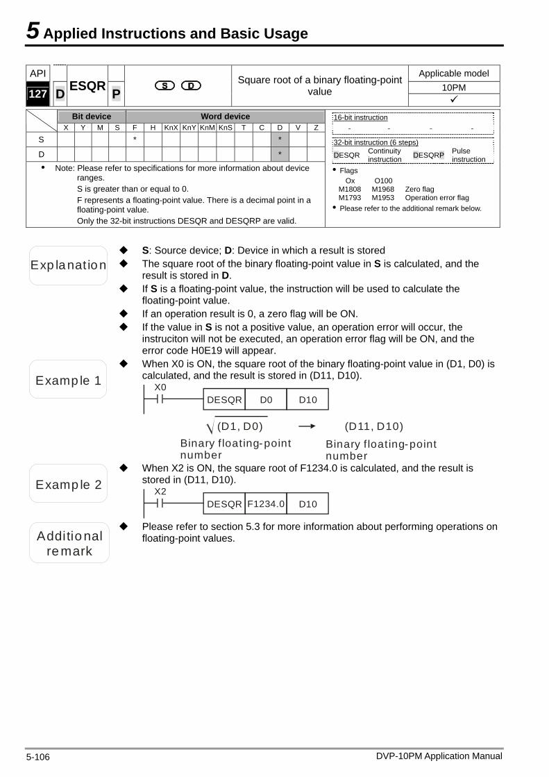
5 Applied Instructions and Basic Usage
DVP-10PM Application Manual 5-106
API Applicable model 10PM 127 D ESQR P
Square root of a binary floating-point value
Bit device Word device
X Y M S F H KnX KnY KnM KnS T C D V Z
S * *
D * Note: Please refer to specifications for more information about device
ranges. S is greater than or equal to 0. F represents a floating-point value. There is a decimal point in a floating-point value. Only the 32-bit instructions DESQR and DESQRP are valid.
16-bit instruction
- - - -
32-bit instruction (6 steps) DESQR Continuity
instruction DESQRP Pulse instruction
Flags Ox O100
M1808 M1968 Zero flag M1793 M1953 Operation error flag Please refer to the additional remark below.
Exp lanat ion The square root of the binary floating-point value in S is calculated, and the result is stored in D.
S: Source device; D: Device in which a result is stored
If S is a floating-point value, the instruction will be used to calculate the floating-point value.
If an operation result is 0, a zero flag will be ON. If the value in S is not a positive value, an operation error will occur, the
instruciton will not be executed, an operation error flag will be ON, and the error code H0E19 will appear.
Examp le 1
When X0 is ON, the square root of the binary floating-point value in (D1, D0) is calculated, and the result is stored in (D11, D10).
X0DESQR D0 D10
Binary f loating-point number
(D1, D0) (D11, D10)Binary f loating-point number
Examp le 2
When X2 is ON, the square root of F1234.0 is calculated, and the result is stored in (D11, D10).
X2DESQR F1234.0 D10
Additional
remark
Please refer to section 5.3 for more information about performing operations on floating-point values.
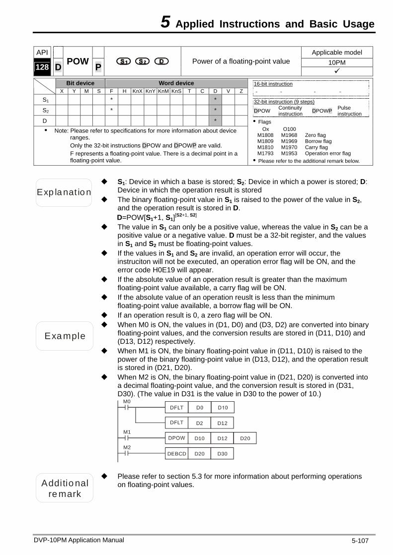
5 Applied Instructions and Basic Usage
API Applicable model 10PM 128 D POW P Power of a floating-point value
Bit device Word device X Y M S F H KnX KnY KnM KnS T C D V Z
S1 * *
S2 * *
D * Note: Please refer to specifications for more information about device
ranges. Only the 32-bit instructions DPOW and DPOWP are valid. F represents a floating-point value. There is a decimal point in a floating-point value.
16-bit instruction - - - -
32-bit instruction (9 steps) DPOW Continuity
instruction DPOWP Pulse instruction
Flags Ox O100
M1808 M1968 Zero flag M1809 M1969 Borrow flag M1810 M1970 Carry flag M1793 M1953 Operation error flag Please refer to the additional remark below.
Exp lanat ion
S1: Device in which a base is stored; S2: Device in which a power is stored; D: Device in which the operation result is stored
The binary floating-point value in S1 is raised to the power of the value in S2, and the operation result is stored in D. D=POW[S1+1, S1][S2+1, S2]
The value in S1 can only be a positive value, whereas the value in S2 can be a positive value or a negative value. D must be a 32-bit register, and the values in S1 and S2 must be floating-point values.
If the values in S1 and S2 are invalid, an operation error will occur, the instruciton will not be executed, an operation error flag will be ON, and the error code H0E19 will appear.
If the absolute value of an operation result is greater than the maximum floating-point value available, a carry flag will be ON.
If the absolute value of an operation reuslt is less than the minimum floating-point value available, a borrow flag will be ON.
If an operation result is 0, a zero flag will be ON.
Example
When M0 is ON, the values in (D1, D0) and (D3, D2) are converted into binary floating-point values, and the conversion results are stored in (D11, D10) and (D13, D12) respectively.
When M1 is ON, the binary floating-point value in (D11, D10) is raised to the power of the binary floating-point value in (D13, D12), and the operation result is stored in (D21, D20).
When M2 is ON, the binary floating-point value in (D21, D20) is converted into a decimal floating-point value, and the conversion result is stored in (D31, D30). (The value in D31 is the value in D30 to the power of 10.)
M0
M1D10 D12
M2DEBCD D20 D30
D2 D12
D20
Additional remark
Please refer to section 5.3 for more information about performing operations on floating-point values.
DVP-10PM Application Manual 5-107
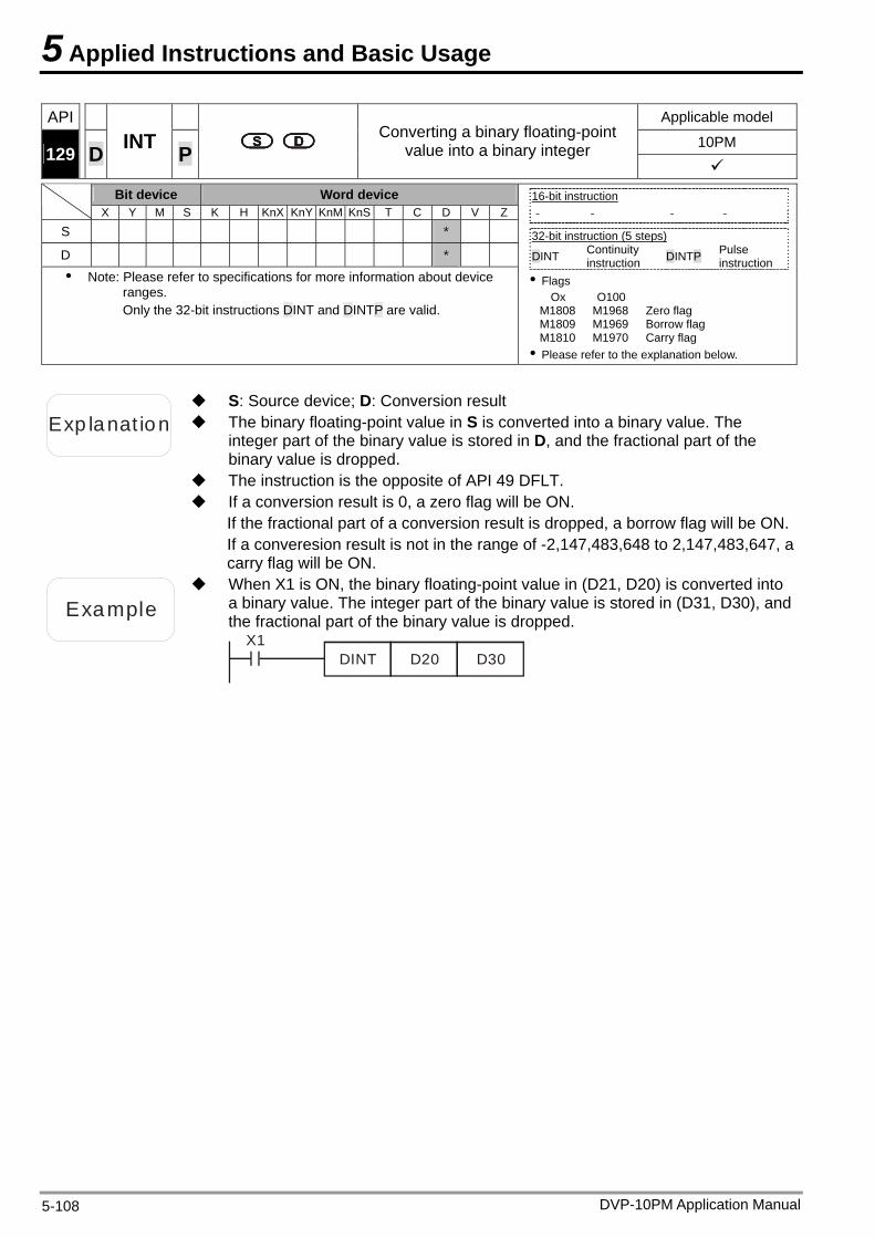
5 Applied Instructions and Basic Usage
API Applicable model
10PM 129
D INT
Converting a binary floating-point value into a binary integer P
Bit device Word device
X Y M S K H KnX KnY KnM KnS T C D V Z
S *
D * Note: Please refer to specifications for more information about device
ranges. Only the 32-bit instructions DINT and DINTP are valid.
16-bit instruction - - - -
32-bit instruction (5 steps) DINT Continuity
instruction DINTP Pulse instruction
Flags Ox O100
M1808 M1968 Zero flag M1809 M1969 Borrow flag M1810 M1970 Carry flag Please refer to the explanation below.
Exp lanat ion The binary floating-point value in S is converted into a binary value. The integer part of the binary value is stored in D, and the fractional part of the binary value is dropped.
S: Source device; D: Conversion result
The instruction is the opposite of API 49 DFLT. If a conversion result is 0, a zero flag will be ON.
If the fractional part of a conversion result is dropped, a borrow flag will be ON.If a converesion result is not in the range of -2,147,483,648 to 2,147,483,647, a carry flag will be ON.
Example
When X1 is ON, the binary floating-point value in (D21, D20) is converted into a binary value. The integer part of the binary value is stored in (D31, D30), and the fractional part of the binary value is dropped.
X1DINT D20 D30
DVP-10PM Application Manual 5-108
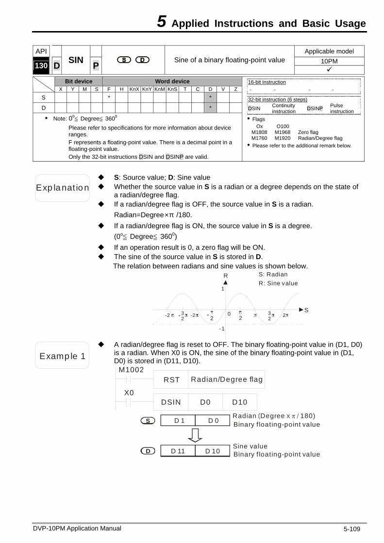
5 Applied Instructions and Basic Usage
DVP-10PM Application Manual 5-109
API Applicable model 10PM 130 D SIN P Sine of a binary floating-point value
Bit device Word device X Y M S F H KnX KnY KnM KnS T C D V Z
S * *
D *
Note: 0o≦ Degree≦ 360 0
Please refer to specifications for more information about device ranges. F represents a floating-point value. There is a decimal point in a floating-point value. Only the 32-bit instructions DSIN and DSINP are valid.
16-bit instruction - - - -
32-bit instruction (6 steps) DSIN Continuity
instruction DSINP Pulse instruction
Flags Ox O100
M1808 M1968 Zero flag M1760 M1920 Radian/Degree flag Please refer to the additional remark below.
Exp lanat ion Whether the source value in S is a radian or a degree depends on the state of a radian/degree flag.
S: Source value; D: Sine value
If a radian/degree flag is OFF, the source value in S is a radian. Radian=Degree×π /180.
If a radian/degree flag is ON, the source value in S is a degree. (0o≦ Degree≦ 3600)
If an operation result is 0, a zero flag will be ON. The sine of the source value in S is stored in D.
The relation between radians and sine values is shown below. R
S
S: RadianR: Sine value
-2 32
-2 23222-
1
-1
0-
Examp le 1
A radian/degree flag is reset to OFF. The binary floating-point value in (D1, D0) is a radian. When X0 is ON, the sine of the binary floating-point value in (D1, D0) is stored in (D11, D10).
M1002RST Radian/Degree flag
X0DSIN D0 D10
D 1 D 0S
D D 11 D 10Sine value
Binary f loating-point valueRadian Degree 180)( X /
Binary f loating-point value
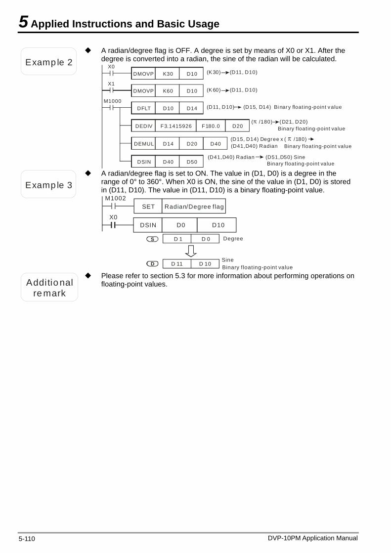
5 Applied Instructions and Basic Usage
DVP-10PM Application Manual 5-110
Examp le 2
A radian/degree flag is OFF. A degree is set by means of X0 or X1. After the degree is converted into a radian, the sine of the radian will be calculated.
X0DMOVP K30 D10
X1DMOVP K60 D10
M1000DFLT D10 D14
DEDIV F3.1415926 F180.0 D20
DEMUL D14 D20 D40
DSIN D40 D50
(K 30) (D11, D10)
(K 60) (D11, D10)
(D11, D10) (D15, D14) Bi nary floating-point v alue
( /180) (D21, D20)Binary f loating-point value
(D15, D14) x ( /180) Degree(D41,D40) Radian Binary f loating-point value
(D41,D40) Radian (D51,D50) SineBinary floating-point value
Examp le 3
A radian/degree flag is set to ON. The value in (D1, D0) is a degree in the range of 0° to 360°. When X0 is ON, the sine of the value in (D1, D0) is stored in (D11, D10). The value in (D11, D10) is a binary floating-point value.
Radian/Degree flagM1002
SET
X0DSIN D0 D10
D 1 D 0S
D D 11 D 10SineBinary f loating-point value
Degree
Additional
remark
Please refer to section 5.3 for more information about performing operations on floating-point values.
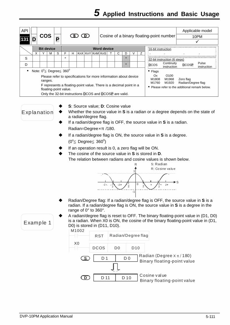
5 Applied Instructions and Basic Usage
DVP-10PM Application Manual 5-111
API Applicable model 10PM 131 D COS P Cosine of a binary floating-point number
Bit device Word device X Y M S F H KnX KnY KnM KnS T C D V Z
S * *
D *
Note: 0o≦ Degree≦ 360 0
Please refer to specifications for more information about device ranges. F represents a floating-point value. There is a decimal point in a floating-point value. Only the 32-bit instructions DCOS and DCOSP are valid.
16-bit instruction - - - -
32-bit instruction (6 steps) DCOS Continuity
instruction DCOSP Pulse instruction
Flags Ox O100
M1808 M1968 Zero flag M1760 M1920 Radian/Degree flag Please refer to the additional remark below.
Exp lanat ion Whether the source value in S is a radian or a degree depends on the state of a radian/degree flag.
S: Source value; D: Cosine value
If a radian/degree flag is OFF, the source value in S is a radian. Radian=Degree×π /180.
If a radian/degree flag is ON, the source value in S is a degree. (0o≦ Degree≦ 3600)
If an operation result is 0, a zero flag will be ON. The cosine of the source value in S is stored in D.
The relation between radians and cosine values is shown below. R
S-2 3
2-2 23
222-
1
-1
0-
S: Radi anR: Co sine va lu e
Radian/Degree flag: If a radian/degree flag is OFF, the source value in S is a
radian. If a radian/degree flag is ON, the source value in S is a degree in the range of 0° to 360°.
Examp le 1
A radian/degree flag is reset to OFF. The binary floating-point value in (D1, D0) is a radian. When X0 is ON, the cosine of the binary floating-point value in (D1, D0) is stored in (D11, D10).
Radian/Degree flagM1002
RST
X0DCOS D0 D10
Cosine val ue
Binary floating-point valueRadian Degree 180)( X /
Binary floating-point value
D 1 D 0S
D D 11 D 10
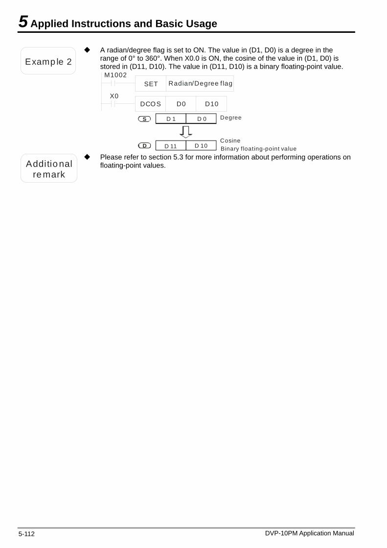
5 Applied Instructions and Basic Usage
DVP-10PM Application Manual 5-112
Examp le 2
A radian/degree flag is set to ON. The value in (D1, D0) is a degree in the range of 0° to 360°. When X0.0 is ON, the cosine of the value in (D1, D0) is stored in (D11, D10). The value in (D11, D10) is a binary floating-point value.
Radian/Degree f lagM1002
SET
X0DCOS D0 D10
CosineBinary floating-point value
Degree D 1 D 0S
D D 11 D 10
Additional
remark
Please refer to section 5.3 for more information about performing operations on floating-point values.
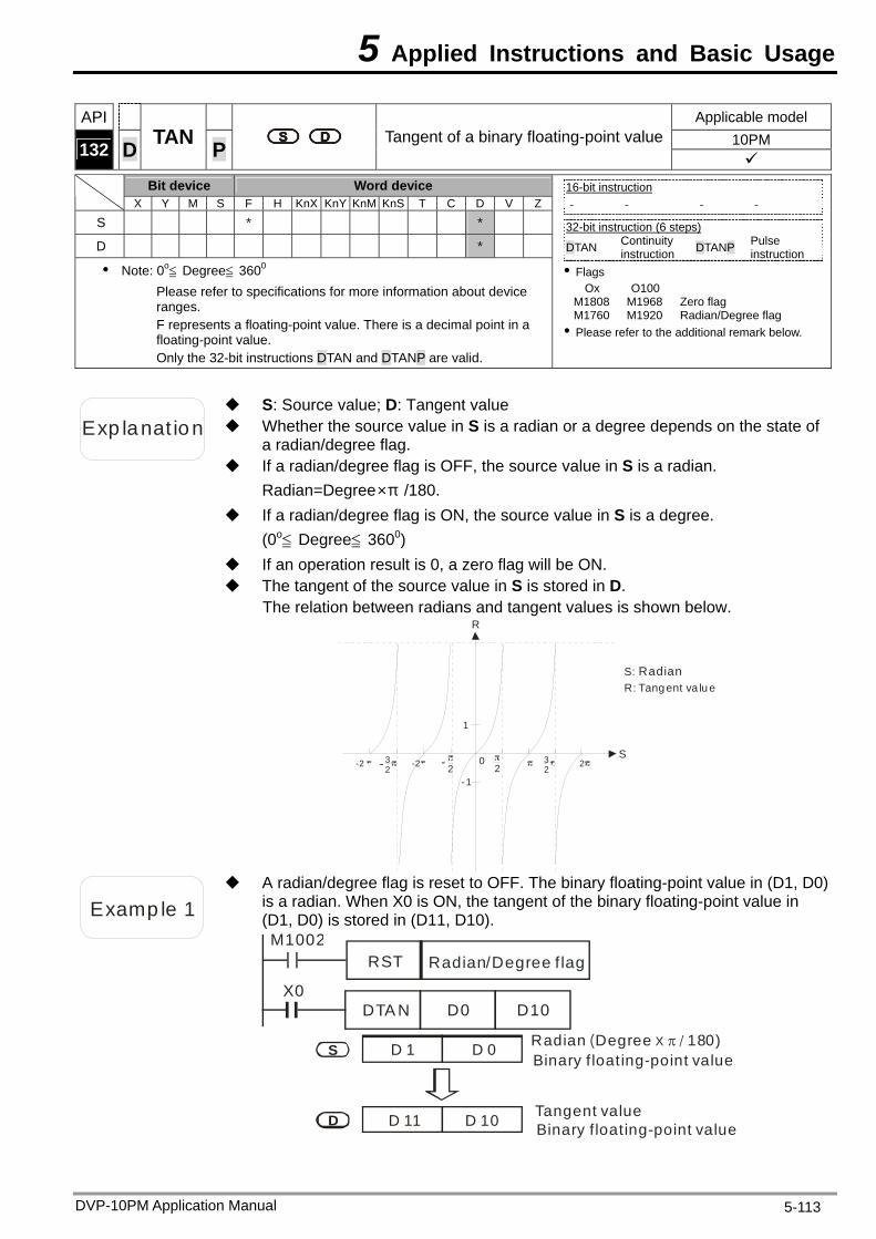
5 Applied Instructions and Basic Usage
DVP-10PM Application Manual 5-113
API Applicable model 10PM 132 D TAN P Tangent of a binary floating-point value
Bit device Word device X Y M S F H KnX KnY KnM KnS T C D V Z
S * *
D *
Note: 0o≦ Degree≦ 360 0
Please refer to specifications for more information about device ranges. F represents a floating-point value. There is a decimal point in a floating-point value. Only the 32-bit instructions DTAN and DTANP are valid.
16-bit instruction - - - -
32-bit instruction (6 steps) DTAN Continuity
instruction DTANP Pulse instruction
Flags Ox O100
M1808 M1968 Zero flag M1760 M1920 Radian/Degree flag Please refer to the additional remark below.
Exp lanat ion Whether the source value in S is a radian or a degree depends on the state of a radian/degree flag.
S: Source value; D: Tangent value
If a radian/degree flag is OFF, the source value in S is a radian. Radian=Degree×π /180.
If a radian/degree flag is ON, the source value in S is a degree. (0o≦ Degree≦ 3600)
If an operation result is 0, a zero flag will be ON. The tangent of the source value in S is stored in D.
The relation between radians and tangent values is shown below. R
S-2 3
2-2 23
222-
1
-1
0-
S: RadianR: Tang ent va lu e
Examp le 1
A radian/degree flag is reset to OFF. The binary floating-point value in (D1, D0) is a radian. When X0 is ON, the tangent of the binary floating-point value in (D1, D0) is stored in (D11, D10).
Radian/Degree f lagM1002
RST
X0DTA N D0 D10
Tangent value
Binary f loating-point valueRadian Degree 180)( X /
Binary f loating-point value
D 1 D 0S
D D 11 D 10
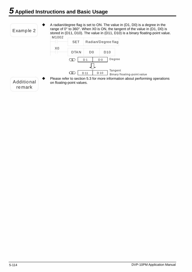
5 Applied Instructions and Basic Usage
Examp le 2
A radian/degree flag is set to ON. The value in (D1, D0) is a degree in the range of 0° to 360°. When X0 is ON, the tangent of the value in (D1, D0) is stored in (D11, D10). The value in (D11, D10) is a binary floating-point value.
Radian/Degree f lagM1002
SET
X0DTA N D0 D10
TangentBinary f loating-point value
Degree D 1 D 0S
D D 11 D 10
Additional remark
Please refer to section 5.3 for more information about performing operations on floating-point values.
DVP-10PM Application Manual 5-114
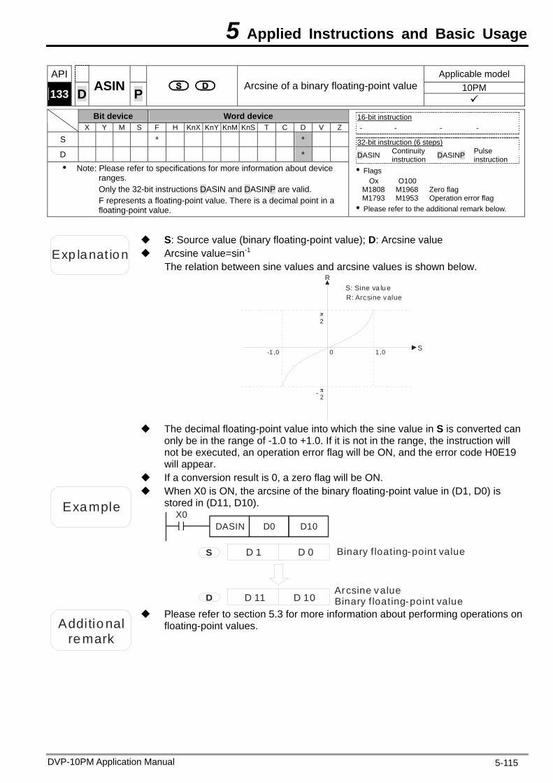
5 Applied Instructions and Basic Usage
DVP-10PM Application Manual 5-115
API Applicable model 10PM 133 D ASIN P Arcsine of a binary floating-point value
Bit device Word device X Y M S F H KnX KnY KnM KnS T C D V Z
S * *
D * Note: Please refer to specifications for more information about device
ranges. Only the 32-bit instructions DASIN and DASINP are valid. F represents a floating-point value. There is a decimal point in a floating-point value.
16-bit instruction - - - -
32-bit instruction (6 steps) DASIN Continuity
instruction DASINP Pulse instruction
Flags Ox O100
M1808 M1968 Zero flag M1793 M1953 Operation error flag Please refer to the additional remark below.
Exp lanat ion Arcsine value=sin-1
S: Source value (binary floating-point value); D: Arcsine value
The relation between sine values and arcsine values is shown below. R
S
2
2-
0 1,0-1,0
S: Sine va lu eR: Arcsine value
The decimal floating-point value into which the sine value in S is converted can
only be in the range of -1.0 to +1.0. If it is not in the range, the instruction will not be executed, an operation error flag will be ON, and the error code H0E19 will appear.
If a conversion result is 0, a zero flag will be ON.
Example
When X0 is ON, the arcsine of the binary floating-point value in (D1, D0) is stored in (D11, D10).
X0DASIN D0 D10
Binary f loating-point value
Binary f loating-point valueD 1 D 0S
D D 11 D 10Arcsine value
Additional
remark
Please refer to section 5.3 for more information about performing operations on floating-point values.
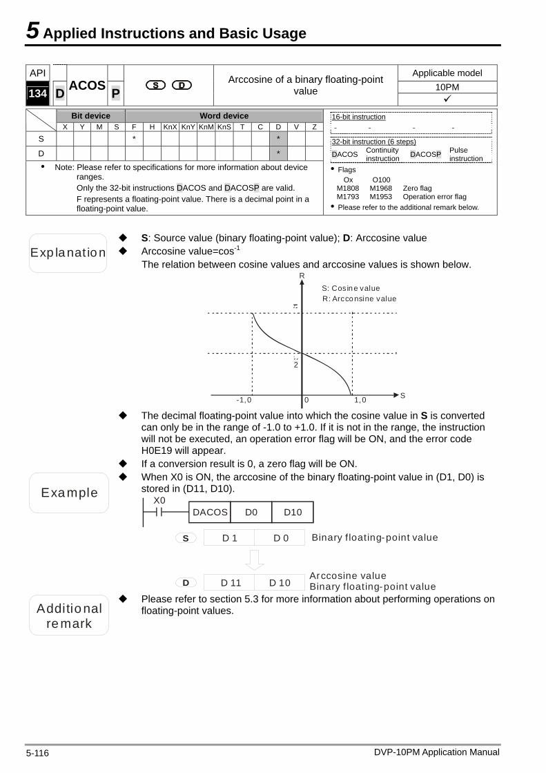
5 Applied Instructions and Basic Usage
DVP-10PM Application Manual 5-116
API Applicable model 10PM 134 D ACOS P
Arccosine of a binary floating-point value
Bit device Word device
X Y M S F H KnX KnY KnM KnS T C D V Z
S * *
D * Note: Please refer to specifications for more information about device
ranges. Only the 32-bit instructions DACOS and DACOSP are valid. F represents a floating-point value. There is a decimal point in a floating-point value.
16-bit instruction - - - -
32-bit instruction (6 steps) DACOS Continuity
instruction DACOSP Pulse instruction
Flags Ox O100
M1808 M1968 Zero flag M1793 M1953 Operation error flag Please refer to the additional remark below.
Exp lanat ion Arccosine value=cos-1
S: Source value (binary floating-point value); D: Arccosine value
The relation between cosine values and arccosine values is shown below. R
S
2
0 1,0-1,0
S: Cosin e valueR: Arcco nsine value
The decimal floating-point value into which the cosine value in S is converted
can only be in the range of -1.0 to +1.0. If it is not in the range, the instruction will not be executed, an operation error flag will be ON, and the error code H0E19 will appear.
If a conversion result is 0, a zero flag will be ON.
Example
When X0 is ON, the arccosine of the binary floating-point value in (D1, D0) is stored in (D11, D10).
X0DACOS D0 D10
Binary f loating-point value
Binary f loating-point valueD 1 D 0S
D D 11 D 10Arccosine value
Additional
remark
Please refer to section 5.3 for more information about performing operations on floating-point values.
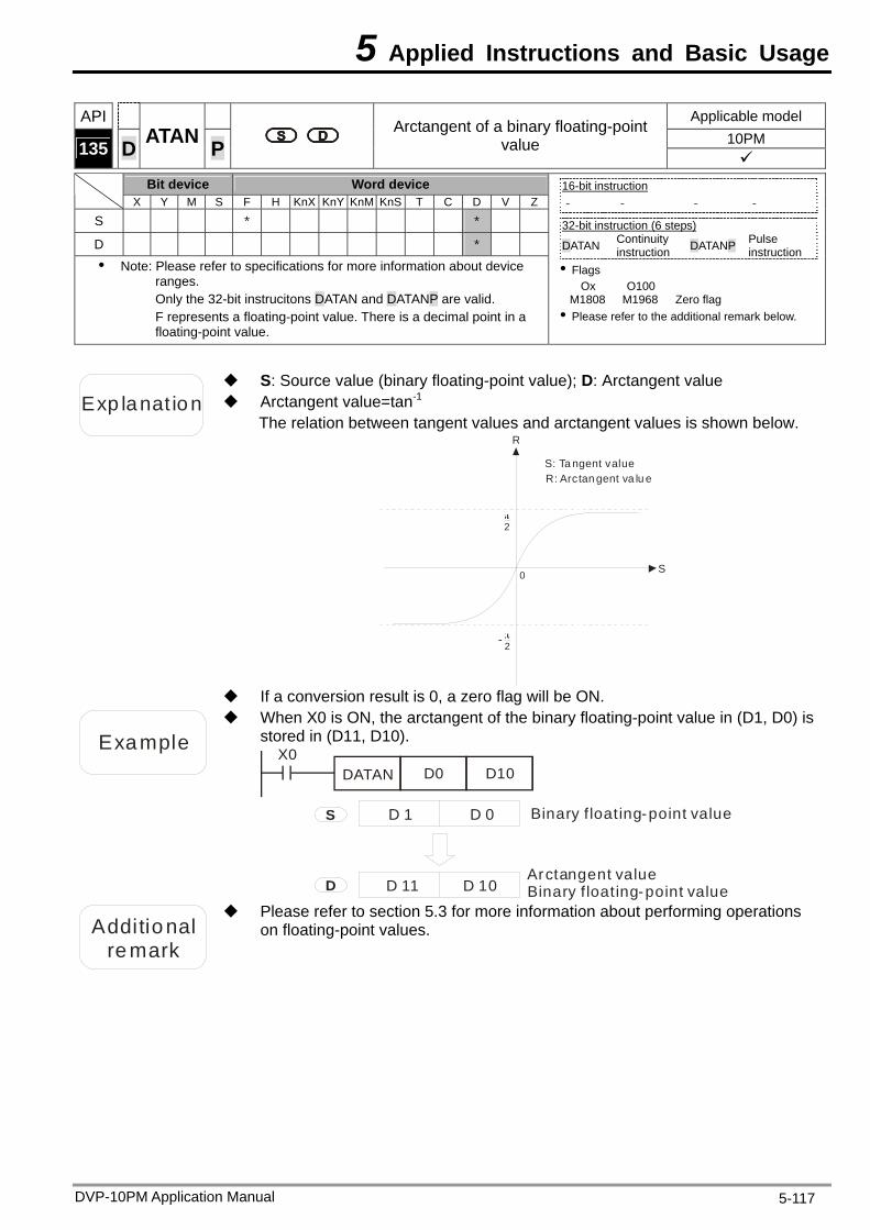
5 Applied Instructions and Basic Usage
API Applicable model 10PM 135 D ATAN P
Arctangent of a binary floating-point value
Bit device Word device
X Y M S F H KnX KnY KnM KnS T C D V Z
S * *
D * Note: Please refer to specifications for more information about device
ranges. Only the 32-bit instrucitons DATAN and DATANP are valid. F represents a floating-point value. There is a decimal point in a floating-point value.
16-bit instruction - - - -
32-bit instruction (6 steps) DATAN Continuity
instruction DATANP Pulse instruction
Flags Ox O100
M1808 M1968 Zero flag Please refer to the additional remark below.
Exp lanat ion Arctangent value=tan-1
S: Source value (binary floating-point value); D: Arctangent value
The relation between tangent values and arctangent values is shown below. R
S
2
2-
0
S: Ta ngent valueR: Arctan gent va lu e
If a conversion result is 0, a zero flag will be ON.
Example
When X0 is ON, the arctangent of the binary floating-point value in (D1, D0) is stored in (D11, D10).
X0DATAN D0 D10
Binary f loating-point value
Binary f loating-point valueD 1 D 0S
D D 11 D 10Arctangent value
Additional remark
Please refer to section 5.3 for more information about performing operations on floating-point values.
DVP-10PM Application Manual 5-117
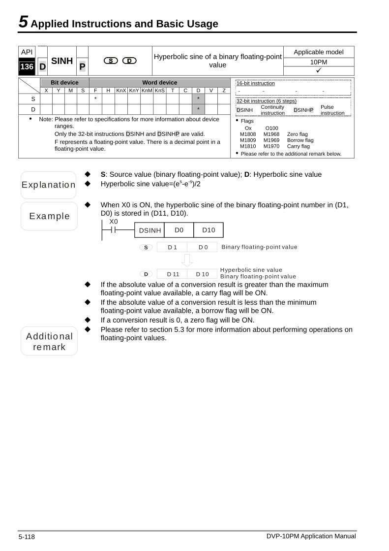
5 Applied Instructions and Basic Usage
DVP-10PM Application Manual 5-118
API Applicable model 10PM 136 D SINH P
Hyperbolic sine of a binary floating-point value
Bit device Word device
X Y M S F H KnX KnY KnM KnS T C D V Z
S * *
D * Note: Please refer to specifications for more information about device
ranges. Only the 32-bit instructions DSINH and DSINHP are valid. F represents a floating-point value. There is a decimal point in a floating-point value.
16-bit instruction - - - -
32-bit instruction (6 steps) DSINH Continuity
instruction DSINHP Pulse instruction
Flags Ox O100
M1808 M1968 Zero flag M1809 M1969 Borrow flag M1810 M1970 Carry flag Please refer to the additional remark below.
Exp lanat ion Hyperbolic sine value=(es-e-s)/2
S: Source value (binary floating-point value); D: Hyperbolic sine value
Example
When X0 is ON, the hyperbolic sine of the binary floating-point number in (D1, D0) is stored in (D11, D10).
X0DSINH D0 D10
Binary f loating-point value
Binary f loating-point valueD 1 D 0S
D D 11 D 10Hyperbolic sine value
If the absolute value of a conversion result is greater than the maximum
floating-point value available, a carry flag will be ON. If the absolute value of a conversion result is less than the minimum
floating-point value available, a borrow flag will be ON. If a conversion result is 0, a zero flag will be ON.
Additional
remark
Please refer to section 5.3 for more information about performing operations on floating-point values.
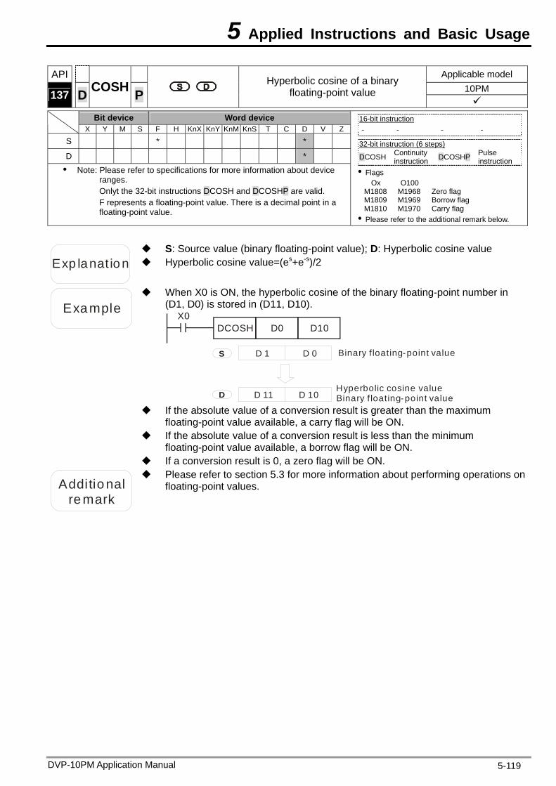
5 Applied Instructions and Basic Usage
DVP-10PM Application Manual 5-119
API Applicable model 10PM 137 D COSH P
Hyperbolic cosine of a binary floating-point value
Bit device Word device
X Y M S F H KnX KnY KnM KnS T C D V Z
S * *
D * Note: Please refer to specifications for more information about device
ranges. Onlyt the 32-bit instructions DCOSH and DCOSHP are valid. F represents a floating-point value. There is a decimal point in a floating-point value.
16-bit instruction - - - -
32-bit instruction (6 steps) DCOSH Continuity
instruction DCOSHP Pulse instruction
Flags Ox O100
M1808 M1968 Zero flag M1809 M1969 Borrow flag M1810 M1970 Carry flag Please refer to the additional remark below.
Exp lanat ion Hyperbolic cosine value=(es+e-s)/2
S: Source value (binary floating-point value); D: Hyperbolic cosine value
Example
When X0 is ON, the hyperbolic cosine of the binary floating-point number in (D1, D0) is stored in (D11, D10).
X0DCOSH D0 D10
Binary f loating-point value
Binary floating-point valueD 1 D 0S
D D 11 D 10Hyperbolic cosine value
If the absolute value of a conversion result is greater than the maximum
floating-point value available, a carry flag will be ON. If the absolute value of a conversion result is less than the minimum
floating-point value available, a borrow flag will be ON. If a conversion result is 0, a zero flag will be ON.
Additional
remark
Please refer to section 5.3 for more information about performing operations on floating-point values.
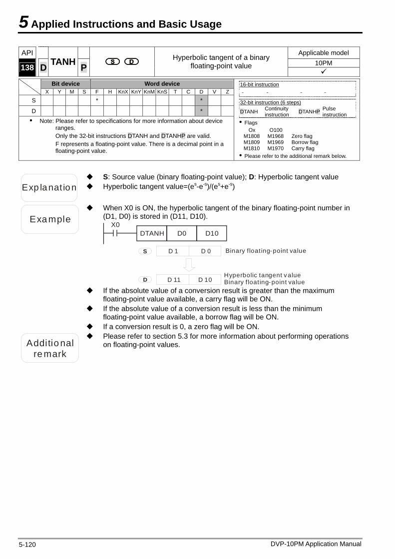
5 Applied Instructions and Basic Usage
API Applicable model 10PM 138 D TANH P
Hyperbolic tangent of a binary floating-point value
Bit device Word device
X Y M S F H KnX KnY KnM KnS T C D V Z
S * *
D * Note: Please refer to specifications for more information about device
ranges. Only the 32-bit instructions DTANH and DTANHP are valid. F represents a floating-point value. There is a decimal point in a floating-point value.
16-bit instruction - - - -
32-bit instruction (6 steps) DTANH Continuity
instruction DTANHP Pulse instruction
Flags Ox O100
M1808 M1968 Zero flag M1809 M1969 Borrow flag M1810 M1970 Carry flag Please refer to the additional remark below.
Exp lanat ion Hyperbolic tangent value=(es-e-s)/(es+e-s)
S: Source value (binary floating-point value); D: Hyperbolic tangent value
Example
When X0 is ON, the hyperbolic tangent of the binary floating-point number in (D1, D0) is stored in (D11, D10).
X0DTANH D0 D10
Binary f loating-point value
Binary f loating-point valueD 1 D 0S
D D 11 D 10Hyperbolic tangent value
If the absolute value of a conversion result is greater than the maximum
floating-point value available, a carry flag will be ON. If the absolute value of a conversion result is less than the minimum
floating-point value available, a borrow flag will be ON. If a conversion result is 0, a zero flag will be ON.
Additional remark
Please refer to section 5.3 for more information about performing operations on floating-point values.
DVP-10PM Application Manual 5-120
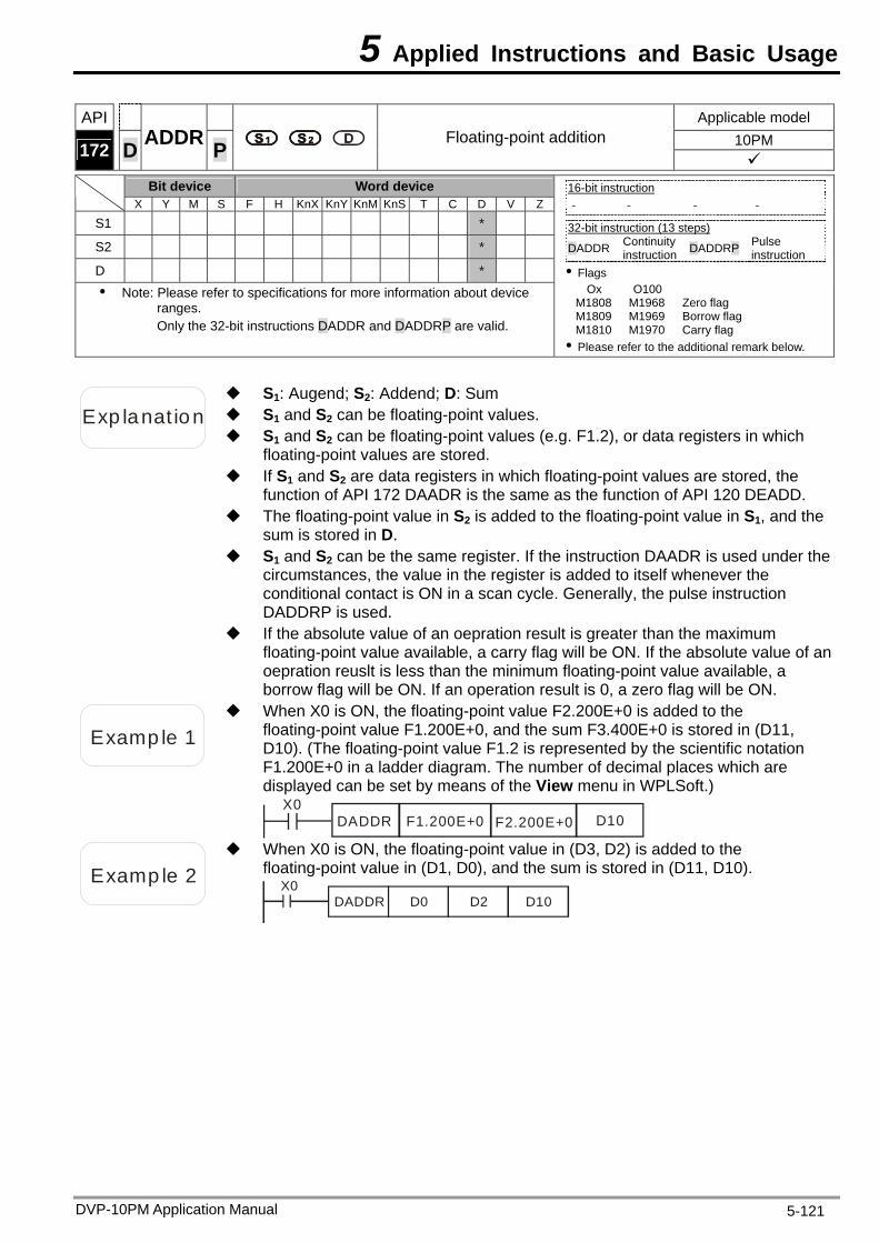
5 Applied Instructions and Basic Usage
API Applicable model 10PM 172 D ADDR P Floating-point addition
Bit device Word device X Y M S F H KnX KnY KnM KnS T C D V Z
S1 *
S2 *
D * Note: Please refer to specifications for more information about device
ranges. Only the 32-bit instructions DADDR and DADDRP are valid.
16-bit instruction - - - -
32-bit instruction (13 steps) DADDR Continuity
instruction DADDRP Pulse instruction
Flags Ox O100
M1808 M1968 Zero flag M1809 M1969 Borrow flag M1810 M1970 Carry flag Please refer to the additional remark below.
Exp lanat ion S1 and S2 can be floating-point values.
S1: Augend; S2: Addend; D: Sum
S1 and S2 can be floating-point values (e.g. F1.2), or data registers in which floating-point values are stored.
If S1 and S2 are data registers in which floating-point values are stored, the function of API 172 DAADR is the same as the function of API 120 DEADD.
The floating-point value in S2 is added to the floating-point value in S1, and the sum is stored in D.
S1 and S2 can be the same register. If the instruction DAADR is used under the circumstances, the value in the register is added to itself whenever the conditional contact is ON in a scan cycle. Generally, the pulse instruction DADDRP is used.
If the absolute value of an oepration result is greater than the maximum floating-point value available, a carry flag will be ON. If the absolute value of an oepration reuslt is less than the minimum floating-point value available, a borrow flag will be ON. If an operation result is 0, a zero flag will be ON.
Examp le 1
When X0 is ON, the floating-point value F2.200E+0 is added to the floating-point value F1.200E+0, and the sum F3.400E+0 is stored in (D11, D10). (The floating-point value F1.2 is represented by the scientific notation F1.200E+0 in a ladder diagram. The number of decimal places which are displayed can be set by means of the View menu in WPLSoft.)
X0DADDR F1.200E+0 D10F2.200E+0
Examp le 2
When X0 is ON, the floating-point value in (D3, D2) is added to the floating-point value in (D1, D0), and the sum is stored in (D11, D10).
X0DADDR D0 D2 D10
DVP-10PM Application Manual 5-121
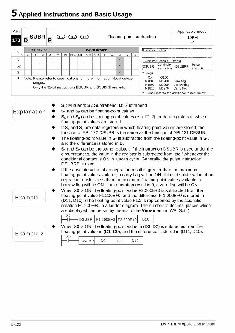
5 Applied Instructions and Basic Usage
API Applicable model 10PM 173 D SUBR P Floating-point subtraction
Bit device Word device X Y M S F H KnX KnY KnM KnS T C D V Z
S1 *
S2 *
D * Note: Please refer to specifications for more information about device
ranges. Only the 32-bit instructions DSUBR and DSUBRP are valid.
16-bit instruction - - - -
32-bit instruction (13 steps) DSUBR Continuity
instruction DSUBRP Pulse instruction
Flags Ox O100
M1808 M1968 Zero flag M1809 M1969 Borrow flag M1810 M1970 Carry flag Please refer to the additional remark below.
Exp lanat ion S1 and S2 can be floating-point values
S1: Minuend; S2: Subtrahend; D: Subtrahend
S1 and S2 can be floating-point values (e.g. F1.2), or data registers in which floating-point values are stored.
If S1 and S2 are data registers in which floating-point values are stored, the function of API 172 DSUBR is the same as the function of API 121 DESUB.
The floating-point value in S2 is subtracted from the floating-point value in S1, and the difference is stored in D.
S1 and S2 can be the same register. If the instruction DSUBR is used under the circumstances, the value in the register is subtracted from itself whenever the conditional contact is ON in a scan cycle. Generally, the pulse instruction DSUBRP is used.
If the absolute value of an oepration result is greater than the maximum floating-point value available, a carry flag will be ON. If the absolute value of an oepration reuslt is less than the minimum floating-point value available, a borrow flag will be ON. If an operation result is 0, a zero flag will be ON.
Examp le 1
When X0 is ON, the floating-point value F2.200E+0 is subtracted from the floating-point value F1.200E+0, and the difference F-1.000E+0 is stored in (D11, D10). (The floating-point value F1.2 is represented by the scientific notation F1.200E+0 in a ladder diagram. The number of decimal places which are displayed can be set by means of the View menu in WPLSoft.)
X0DSUBR F1.200E+0 D10F2.200E+0
Examp le 2
When X0 is ON, the floating-point value in (D3, D2) is subtracted from the floating-point value in (D1, D0), and the difference is stored in (D11, D10).
X0DSUBR D0 D2 D10
DVP-10PM Application Manual 5-122
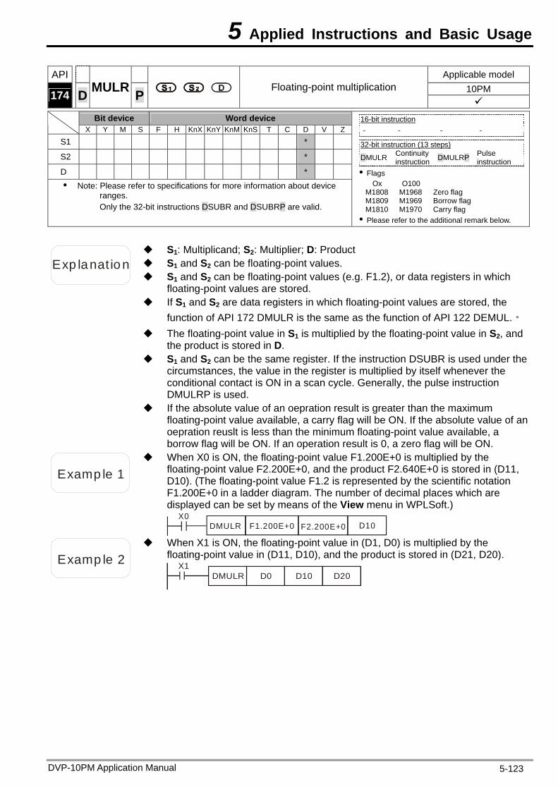
5 Applied Instructions and Basic Usage
API Applicable model 10PM 174 D MULR P Floating-point multiplication
Bit device Word device X Y M S F H KnX KnY KnM KnS T C D V Z
S1 *
S2 *
D * Note: Please refer to specifications for more information about device
ranges. Only the 32-bit instructions DSUBR and DSUBRP are valid.
16-bit instruction - - - -
32-bit instruction (13 steps) DMULR Continuity
instruction DMULRP Pulse instruction
Flags Ox O100
M1808 M1968 Zero flag M1809 M1969 Borrow flag M1810 M1970 Carry flag Please refer to the additional remark below.
Exp lanat ion S1 and S2 can be floating-point values.
S1: Multiplicand; S2: Multiplier; D: Product
S1 and S2 can be floating-point values (e.g. F1.2), or data registers in which floating-point values are stored.
If S1 and S2 are data registers in which floating-point values are stored, the function of API 172 DMULR is the same as the function of API 122 DEMUL.。
The floating-point value in S1 is multiplied by the floating-point value in S2, and the product is stored in D.
S1 and S2 can be the same register. If the instruction DSUBR is used under the circumstances, the value in the register is multiplied by itself whenever the conditional contact is ON in a scan cycle. Generally, the pulse instruction DMULRP is used.
If the absolute value of an oepration result is greater than the maximum floating-point value available, a carry flag will be ON. If the absolute value of an oepration reuslt is less than the minimum floating-point value available, a borrow flag will be ON. If an operation result is 0, a zero flag will be ON.
Examp le 1
When X0 is ON, the floating-point value F1.200E+0 is multiplied by the floating-point value F2.200E+0, and the product F2.640E+0 is stored in (D11, D10). (The floating-point value F1.2 is represented by the scientific notation F1.200E+0 in a ladder diagram. The number of decimal places which are displayed can be set by means of the View menu in WPLSoft.)
X0DMULR F1.200E+0 D10F2.200E+0
Examp le 2
When X1 is ON, the floating-point value in (D1, D0) is multiplied by the floating-point value in (D11, D10), and the product is stored in (D21, D20).
X1D0 D10 D20DMULR
DVP-10PM Application Manual 5-123
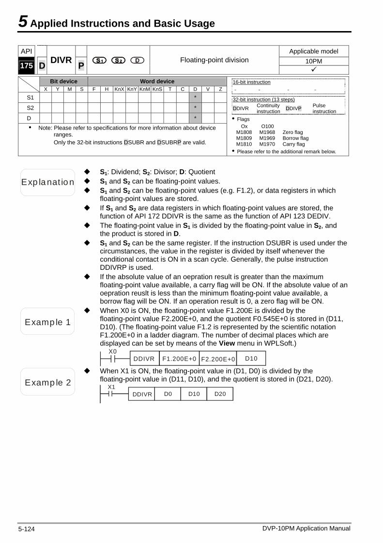
5 Applied Instructions and Basic Usage
API Applicable model 10PM 175 D DIVR P Floating-point division
Bit device Word device X Y M S F H KnX KnY KnM KnS T C D V Z
S1 *
S2 *
D * Note: Please refer to specifications for more information about device
ranges. Only the 32-bit instructions DSUBR and DSUBRP are valid.
16-bit instruction - - - -
32-bit instruction (13 steps) DDIVR Continuity
instruction DDIVP Pulse instruction
Flags Ox O100
M1808 M1968 Zero flag M1809 M1969 Borrow flag M1810 M1970 Carry flag Please refer to the additional remark below.
Exp lanat ion S1 and S2 can be floating-point values.
S1: Dividend; S2: Divisor; D: Quotient
S1 and S2 can be floating-point values (e.g. F1.2), or data registers in which floating-point values are stored.
If S1 and S2 are data registers in which floating-point values are stored, the function of API 172 DDIVR is the same as the function of API 123 DEDIV.
The floating-point value in S1 is divided by the floating-point value in S2, and the product is stored in D.
S1 and S2 can be the same register. If the instruction DSUBR is used under the circumstances, the value in the register is divided by itself whenever the conditional contact is ON in a scan cycle. Generally, the pulse instruction DDIVRP is used.
If the absolute value of an oepration result is greater than the maximum floating-point value available, a carry flag will be ON. If the absolute value of an oepration reuslt is less than the minimum floating-point value available, a borrow flag will be ON. If an operation result is 0, a zero flag will be ON.
Examp le 1
When X0 is ON, the floating-point value F1.200E is divided by the floating-point value F2.200E+0, and the quotient F0.545E+0 is stored in (D11, D10). (The floating-point value F1.2 is represented by the scientific notation F1.200E+0 in a ladder diagram. The number of decimal places which are displayed can be set by means of the View menu in WPLSoft.)
X0DDIVR F1.200E+0 D10F2.200E+0
Examp le 2
When X1 is ON, the floating-point value in (D1, D0) is divided by the floating-point value in (D11, D10), and the quotient is stored in (D21, D20).
X1DDIVR D0 D10 D20
DVP-10PM Application Manual 5-124
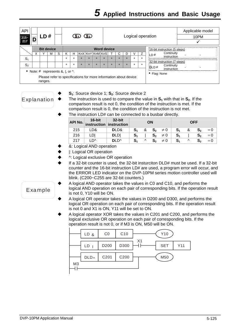
5 Applied Instructions and Basic Usage
DVP-10PM Application Manual 5-125
API Applicable model 10PM 215~
217 D LD# Logical operation
Bit device Word device
X Y M S K H KnX KnY KnM KnS T C D V Z
S1 * * * * * * * * * * *
S2 * * * * * * * * * * *
Note:# represents &, |, or ^. Please refer to specifications for more information about device ranges.
16-bit instruction (5 steps) LD# Continuity
instruction - -
32-bit instruction (7 steps) DLD# Continuity
instruction - -
Flag: None
Exp lanat ion The instruction is used to compare the value in S1 with that in S2. If the comparison result is not 0, the condition of the instruction is met. If the comparison result is 0, the condition of the instruction is not met.
S1: Source device 1; S2: Source device 2
The instruction LD# can be connected to a busbar directly.
API No. 16-bit instruction
32-bit instruction ON OFF
215 LD& DLD& S1 & S2 0 S1 & S2 0216 LD| DLD| S1 | S2 0 S1 | S2 0217 LD^ DLD^ S1 ^ S2 0 S1 ^ S2 0
&: Logical AND operation |: Logical OR operation ^: Logical exclusive OR operation If a 32-bit counter is used, the 32-bit insturciton DLD# must be used. If a 32-bit
counter and the 16-bit instruction LD# are used, a program error will occur, and the ERROR LED indicator on the DVP-10PM series motion controller used will blink. (C200~C255 are 32-bit counters.)
Example
A logical AND operator takes the values in C0 and C10, and performs the logical AND operation on each pair of corresponding bits. If the operation result is not 0, Y10 will be ON.
A logical OR operator takes the values in D200 and D300, and performs the logical OR operation on each pair of corresponding bits. If the operation result is not 0 and X1 is ON, Y11 will be set to ON.
A logical operator XOR takes the values in C201 and C200, and performs the logical exclusive OR operation on each pair of corresponding bits. If the operation result is not 0, or if M3 is ON, M50 will be ON.
M3
DLD C201 C200 M50
LD C0 C10
LD D200 D300 SETX1
&
^
I Y11
Y10
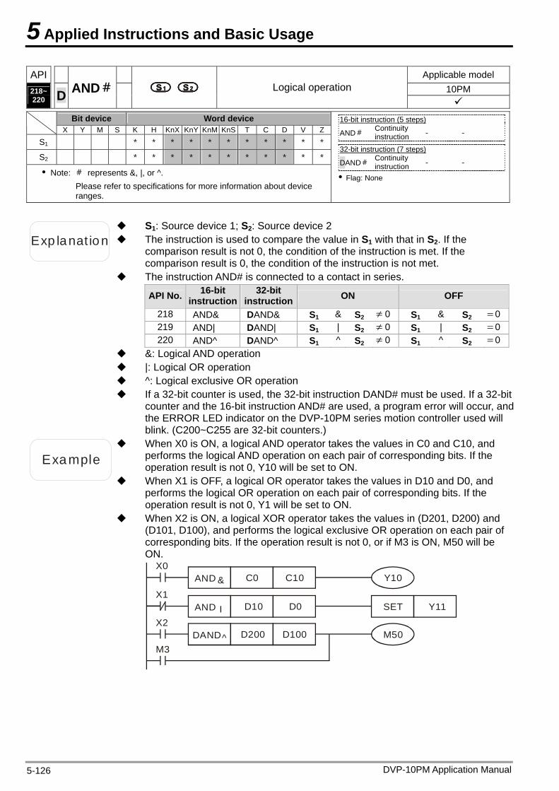
5 Applied Instructions and Basic Usage
DVP-10PM Application Manual 5-126
API Applicable model 10PM 218~
220 D AND# Logical operation
Bit device Word device
X Y M S K H KnX KnY KnM KnS T C D V Z
S1 * * * * * * * * * * *
S2 * * * * * * * * * * *
Note: # represents &, |, or ^. Please refer to specifications for more information about device ranges.
16-bit instruction (5 steps) AND# Continuity
instruction - -
32-bit instruction (7 steps) DAND#
Continuity instruction - -
Flag: None
Exp lanat ion The instruction is used to compare the value in S1 with that in S2. If the comparison result is not 0, the condition of the instruction is met. If the comparison result is 0, the condition of the instruction is not met.
S1: Source device 1; S2: Source device 2
The instruction AND# is connected to a contact in series.
API No. 16-bit instruction
32-bit instruction ON OFF
218 AND& DAND& S1 & S2 0 S1 & S2 0219 AND| DAND| S1 | S2 0 S1 | S2 0220 AND^ DAND^ S1 ^ S2 0 S1 ^ S2 0
&: Logical AND operation |: Logical OR operation ^: Logical exclusive OR operation If a 32-bit counter is used, the 32-bit instruction DAND# must be used. If a 32-bit
counter and the 16-bit instruction AND# are used, a program error will occur, and the ERROR LED indicator on the DVP-10PM series motion controller used will blink. (C200~C255 are 32-bit counters.)
Example
When X0 is ON, a logical AND operator takes the values in C0 and C10, and performs the logical AND operation on each pair of corresponding bits. If the operation result is not 0, Y10 will be set to ON.
When X1 is OFF, a logical OR operator takes the values in D10 and D0, and performs the logical OR operation on each pair of corresponding bits. If the operation result is not 0, Y1 will be set to ON.
When X2 is ON, a logical XOR operator takes the values in (D201, D200) and (D101, D100), and performs the logical exclusive OR operation on each pair of corresponding bits. If the operation result is not 0, or if M3 is ON, M50 will be ON.
M3DAND D200 D100 M50
AND C0 C10
AND D10 D0 SET
&
^
I Y11
Y10X0
X1
X2
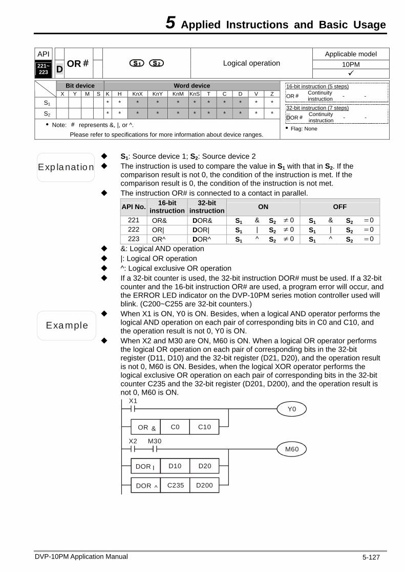
5 Applied Instructions and Basic Usage
DVP-10PM Application Manual 5-127
API Applicable model 10PM 221~
223 D OR# Logical operation
Bit device Word device
X Y M S K H KnX KnY KnM KnS T C D V Z
S1 * * * * * * * * * * *
S2 * * * * * * * * * * *
Note: # represents &, |, or ^. Please refer to specifications for more information about device ranges.
16-bit instruction (5 steps) OR# Continuity
instruction - -
32-bit instruction (7 steps) DOR# Continuity
instruction - -
Flag: None
Exp lanat ion The instruction is used to compare the value in S1 with that in S2. If the comparison result is not 0, the condition of the instruction is met. If the comparison result is 0, the condition of the instruction is not met.
S1: Source device 1; S2: Source device 2
The instruction OR# is connected to a contact in parallel.
API No. 16-bit instruction
32-bit instruction ON OFF
221 OR& DOR& S1 & S2 0 S1 & S2 0222 OR| DOR| S1 | S2 0 S1 | S2 0223 OR^ DOR^ S1 ^ S2 0 S1 ^ S2 0
&: Logical AND operation |: Logical OR operation ^: Logical exclusive OR operation If a 32-bit counter is used, the 32-bit instruction DOR# must be used. If a 32-bit
counter and the 16-bit instruction OR# are used, a program error will occur, and the ERROR LED indicator on the DVP-10PM series motion controller used will blink. (C200~C255 are 32-bit counters.)
Example
When X1 is ON, Y0 is ON. Besides, when a logical AND operator performs the logical AND operation on each pair of corresponding bits in C0 and C10, and the operation result is not 0, Y0 is ON.
When X2 and M30 are ON, M60 is ON. When a logical OR operator performs the logical OR operation on each pair of corresponding bits in the 32-bit register (D11, D10) and the 32-bit register (D21, D20), and the operation result is not 0, M60 is ON. Besides, when the logical XOR operator performs the logical exclusive OR operation on each pair of corresponding bits in the 32-bit counter C235 and the 32-bit register (D201, D200), and the operation result is not 0, M60 is ON.
DOR C235 D200
OR C0 C10
DOR D10 D20
&
^
I
Y0
X2
X1
M30M60
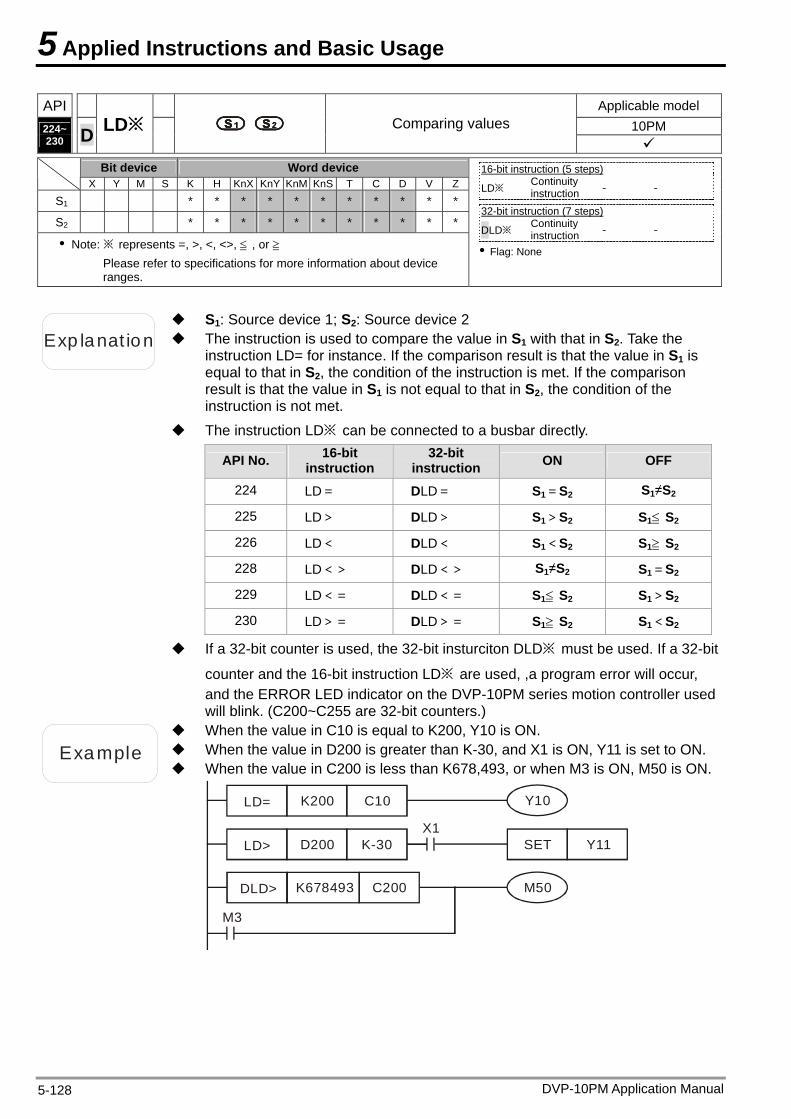
5 Applied Instructions and Basic Usage
API Applicable model 10PM 224~
230 D LD※ Comparing values
Bit device Word device
X Y M S K H KnX KnY KnM KnS T C D V Z
S1 * * * * * * * * * * *
S2 * * * * * * * * * * *
Note: ※ represents =, >, <, <>, ≦ , or ≧ Please refer to specifications for more information about device ranges.
16-bit instruction (5 steps) LD※ Continuity
instruction - -
32-bit instruction (7 steps) DLD※ Continuity
instruction - -
Flag: None
Exp lanat ion The instruction is used to compare the value in S1 with that in S2. Take the instruction LD= for instance. If the comparison result is that the value in S1 is equal to that in S2, the condition of the instruction is met. If the comparison result is that the value in S1 is not equal to that in S2, the condition of the instruction is not met.
S1: Source device 1; S2: Source device 2
The instruction LD※ can be connected to a busbar directly.
API No. 16-bit instruction
32-bit instruction ON OFF
224 LD= DLD= S1=S2 S1≠S2
225 LD> DLD> S1>S2 S1≦ S2
226 LD< DLD< S1<S2 S1≧ S2
228 LD<> DLD<> S1≠S2 S1=S2
229 LD<= DLD<= S1≦ S2 S1>S2
230 LD>= DLD>= S1≧ S2 S1<S2
If a 32-bit counter is used, the 32-bit insturciton DLD※ must be used. If a 32-bit
counter and the 16-bit instruction LD※ are used, ,a program error will occur, and the ERROR LED indicator on the DVP-10PM series motion controller used will blink. (C200~C255 are 32-bit counters.)
Example When the value in D200 is greater than K-30, and X1 is ON, Y11 is set to ON.
When the value in C10 is equal to K200, Y10 is ON.
When the value in C200 is less than K678,493, or when M3 is ON, M50 is ON.
LD= K200 C10
DLD> K678493 C200
M3
Y10
LD> D200 K-30X1
SET Y11
M50
DVP-10PM Application Manual 5-128
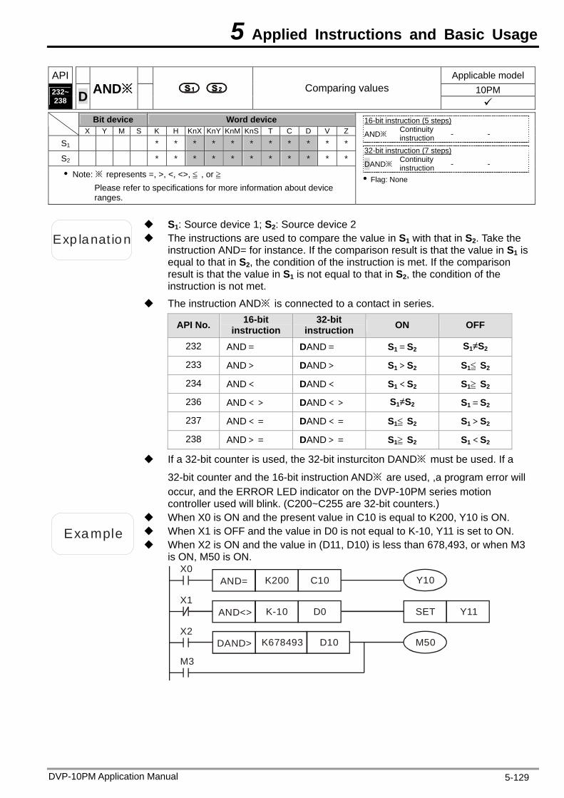
5 Applied Instructions and Basic Usage
API Applicable model 10PM 232~
238 D AND※ Comparing values
Bit device Word device
X Y M S K H KnX KnY KnM KnS T C D V Z
S1 * * * * * * * * * * *
S2 * * * * * * * * * * *
Note: ※ represents =, >, <, <>, ≦ , or ≧ Please refer to specifications for more information about device ranges.
16-bit instruction (5 steps) AND※ Continuity
instruction - -
32-bit instruction (7 steps) DAND※
Continuity instruction - -
Flag: None
Exp lanat ion The instructions are used to compare the value in S1 with that in S2. Take the instruction AND= for instance. If the comparison result is that the value in S1 is equal to that in S2, the condition of the instruction is met. If the comparison result is that the value in S1 is not equal to that in S2, the condition of the instruction is not met.
S1: Source device 1; S2: Source device 2
The instruction AND※ is connected to a contact in series.
API No. 16-bit instruction
32-bit instruction ON OFF
232 AND= DAND= S1=S2 S1≠S2
233 AND> DAND> S1>S2 S1≦ S2
234 AND< DAND< S1<S2 S1≧ S2
236 AND<> DAND<> S1≠S2 S1=S2
237 AND<= DAND<= S1≦ S2 S1>S2
238 AND>= DAND>= S1≧ S2 S1<S2
If a 32-bit counter is used, the 32-bit insturciton DAND※ must be used. If a
32-bit counter and the 16-bit instruction AND※ are used, ,a program error will occur, and the ERROR LED indicator on the DVP-10PM series motion controller used will blink. (C200~C255 are 32-bit counters.)
Example When X1 is OFF and the value in D0 is not equal to K-10, Y11 is set to ON.
When X0 is ON and the present value in C10 is equal to K200, Y10 is ON.
When X2 is ON and the value in (D11, D10) is less than 678,493, or when M3 is ON, M50 is ON.
AND= K200 C10
DAND> K678493 D10
M3
Y10
AND<> K-10 D0 SET Y11
M50X2
X1
X0
DVP-10PM Application Manual 5-129
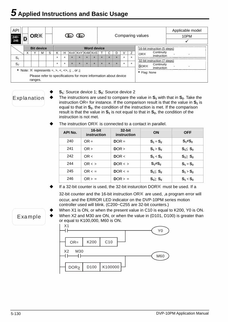
5 Applied Instructions and Basic Usage
API Applicable model 10PM 240~
246 D OR※ Comparing values
Bit device Word device
X Y M S K H KnX KnY KnM KnS T C D V Z
S1 * * * * * * * * * * *
S2 * * * * * * * * * * *
Note: ※ represents =, >, <, <>, ≦ , or ≧ Please refer to specifications for more information about device ranges.
16-bit instruction (5 steps) OR※ Continuity
instruction - -
32-bit instruction (7 steps) DOR※ Continuity
instruction - -
Flag: None
Exp lanat ion The instructions are used to compare the value in S1 with that in S2. Take the instruction OR= for instance. If the comparison result is that the value in S1 is equal to that in S2, the condition of the instruction is met. If the comparison result is that the value in S1 is not equal to that in S2, the condition of the instruction is not met.
S1: Source device 1; S2: Source device 2
The instruction OR※ is connected to a contact in parallel.
API No. 16-bit instruction
32-bit instruction ON OFF
240 OR= DOR= S1=S2 S1≠S2
241 OR> DOR> S1>S2 S1≦ S2
242 OR< DOR< S1<S2 S1≧ S2
244 OR<> DOR<> S1≠S2 S1=S2
245 OR<= DOR<= S1≦ S2 S1>S2
246 OR>= DOR>= S1≧ S2 S1<S2
If a 32-bit counter is used, the 32-bit insturciton DOR※ must be used. If a
32-bit counter and the 16-bit instruction OR※ are used, ,a program error will occur, and the ERROR LED indicator on the DVP-10PM series motion controller used will blink. (C200~C255 are 32-bit counters.)
Example When X2 and M30 are ON, or when the value in (D101, D100) is greater than or equal to K100,000, M60 is ON.
When X1 is ON, or when the present value in C10 is equal to K200, Y0 is ON.
OR= K200 C10
DOR> D100 K100000
Y0
X2
X1
M30M60
=
DVP-10PM Application Manual 5-130
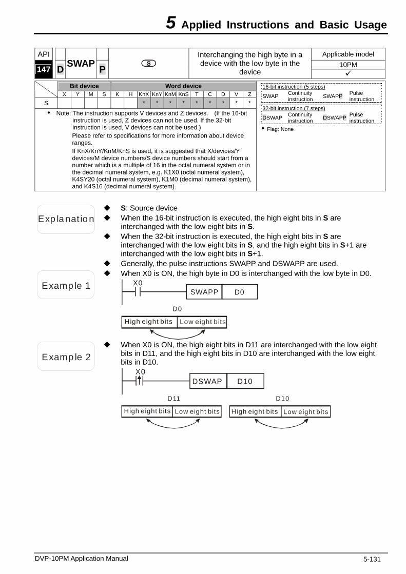
5 Applied Instructions and Basic Usage
API Applicable model 10PM 147
D SWAP Interchanging the high byte in a device with the low byte in the
device P Bit device Word device
X Y M S K H KnX KnY KnM KnS T C D V Z
S * * * * * * * * *
Note: The instruction supports V devices and Z devices. (If the 16-bit instruction is used, Z devices can not be used. If the 32-bit instruction is used, V devices can not be used.) Please refer to specifications for more information about device ranges. If KnX/KnY/KnM/KnS is used, it is suggested that X/devices/Y devices/M device numbers/S device numbers should start from a number which is a multiple of 16 in the octal numeral system or in the decimal numeral system, e.g. K1X0 (octal numeral system), K4SY20 (octal numeral system), K1M0 (decimal numeral system), and K4S16 (decimal numeral system).
16-bit instruction (5 steps) SWAP Continuity
instruction SWAPP Pulse instruction
32-bit instruction (7 steps) DSWAP Continuity
instruction DSWAPP Pulse instruction
Flag: None
Exp lanat ion When the 16-bit instruction is executed, the high eight bits in S are interchanged with the low eight bits in S.
S: Source device
When the 32-bit instruction is executed, the high eight bits in S are interchanged with the low eight bits in S, and the high eight bits in S+1 are interchanged with the low eight bits in S+1.
Generally, the pulse instructions SWAPP and DSWAPP are used.
Examp le 1
When X0 is ON, the high byte in D0 is interchanged with the low byte in D0.
D0SWAPPX0
High eight bits
D0
Low eight bits
Examp le 2
When X0 is ON, the high eight bits in D11 are interchanged with the low eight bits in D11, and the high eight bits in D10 are interchanged with the low eight bits in D10.
D10DSWAPX0
Low eight bits
D11 D10
High eight bits High eight bits Low eight bits
DVP-10PM Application Manual 5-131

5 Applied Instructions and Basic Usage
API Applicable model 10PM 154
D RAND P Random value
Bit device Word device X Y M S K H KnX KnY KnM KnS T C D V Z
S1 * * * * * * * * * * *
S2 * * * * * * * * * * *
D * * * * * * * *
Note: The instruction supports V devices and Z devices. (If the 16-bit instruction is used, Z devices can not be used. If the 32-bit instruction is used, V devices can not be used.) Please refer to specifications for more information about device ranges. If KnX/KnY/KnM/KnS is used, it is suggested that X/devices/Y devices/M device numbers/S device numbers should start from a number which is a multiple of 16 in the octal numeral system or in the decimal numeral system, e.g. K1X0 (octal numeral system), K4SY20 (octal numeral system), K1M0 (decimal numeral system), and K4S16 (decimal numeral system).
16-bit instruction (5 steps) RAND Continuity
instruction RANDP Pulse instruction
32-bit instruction (7 steps) DRAND Continuity
instruction DRANDP Pulse instruction
Flag: None
Exp lanat ion 16-bit instruction: The value in S1 and the value in S2 are in the range of K0 to K32,767.
S1: Minimum random value; S2: Maximum random value; D: Result
32-bit instruction: The value in S1 and the value in S2 are in the range of K0 to K2,147,483,647.
The value in S1 must be less than the value in S2. If the value in S1 is greater than the value in S2, an operation error will occur.
Example
When X0 is ON, the instruction RAND is used to generate a random value in the range of the value in D0 to the value in D10, and the random value is stored in D20.
X0RAND D0 D10 D20
DVP-10PM Application Manual 5-132
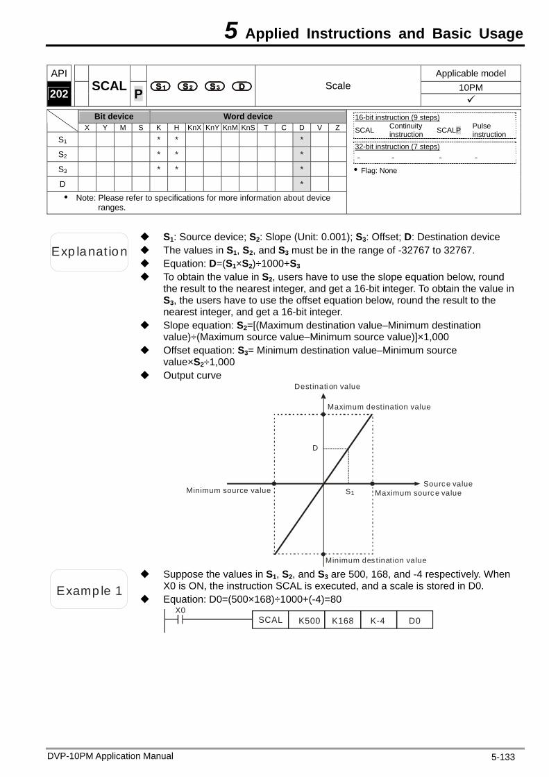
5 Applied Instructions and Basic Usage
API Applicable model 10PM 202
SCAL P Scale
Bit device Word device X Y M S K H KnX KnY KnM KnS T C D V Z
S1 * * * S2 * * * S3 * * * D * Note: Please refer to specifications for more information about device
ranges.
16-bit instruction (9 steps) SCAL Continuity
instruction SCALP Pulse instruction
32-bit instruction (7 steps) - - - -
Flag: None
Exp lanat ion The values in S1, S2, and S3 must be in the range of -32767 to 32767.
S1: Source device; S2: Slope (Unit: 0.001); S3: Offset; D: Destination device
Equation: D=(S1×S2)÷1000+S3 To obtain the value in S2, users have to use the slope equation below, round
the result to the nearest integer, and get a 16-bit integer. To obtain the value in S3, the users have to use the offset equation below, round the result to the nearest integer, and get a 16-bit integer.
Slope equation: S2=[(Maximum destination value–Minimum destination value)÷(Maximum source value–Minimum source value)]×1,000
Offset equation: S3= Minimum destination value–Minimum source value×S2÷1,000
Output curve
D
S1Source value
Maximum sourc e valueMinimum source value
Destinati on value
Maximum destination value
Minimum des tination value
Examp le 1
Suppose the values in S1, S2, and S3 are 500, 168, and -4 respectively. When X0 is ON, the instruction SCAL is executed, and a scale is stored in D0.
Equation: D0=(500×168)÷1000+(-4)=80 X0
SCAL K500 K168 K-4 D0
DVP-10PM Application Manual 5-133
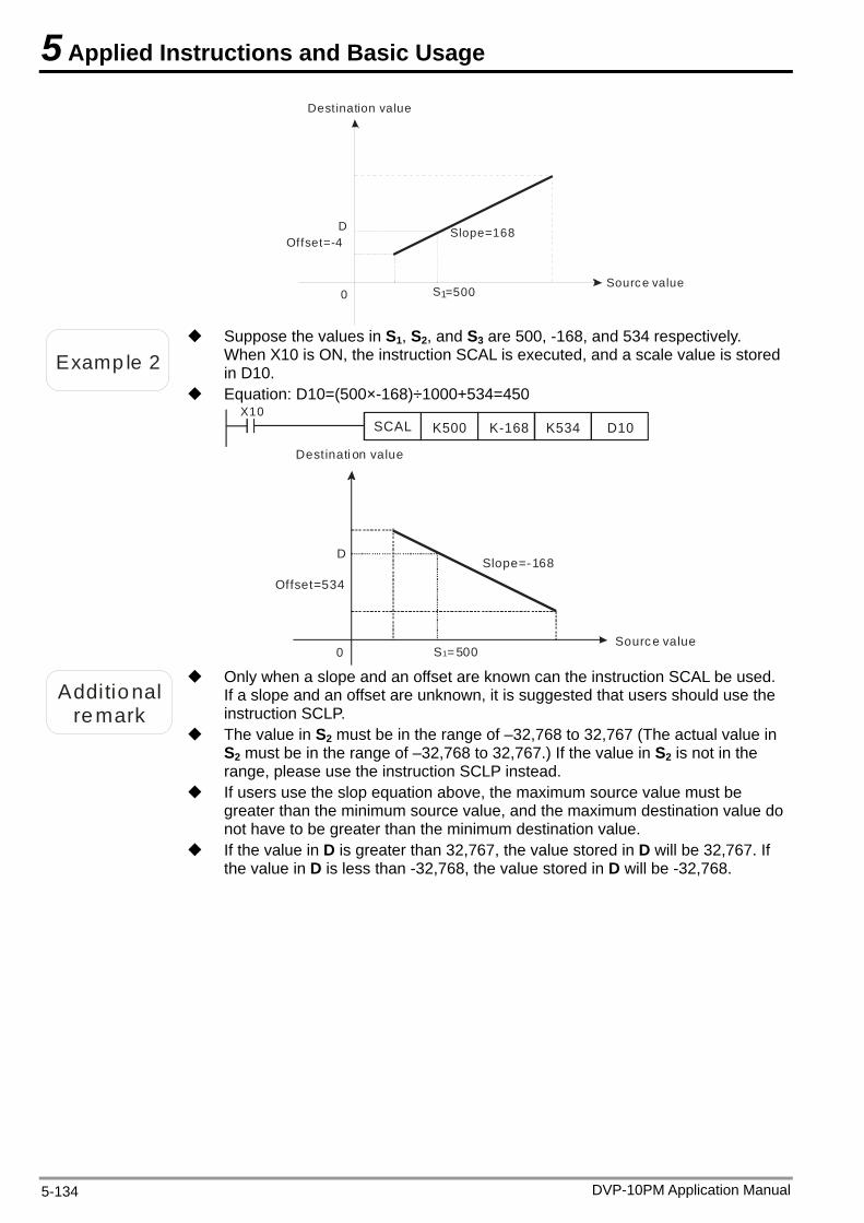
5 Applied Instructions and Basic Usage
DVP-10PM Application Manual 5-134
Source value
Destination value
D
S10 =500
Slope=168Offset=-4
Examp le 2
Suppose the values in S1, S2, and S3 are 500, -168, and 534 respectively. When X10 is ON, the instruction SCAL is executed, and a scale value is stored in D10.
Equation: D10=(500×-168)÷1000+534=450 X10
SCAL K500 K-168 K534 D10
Source value
Destinati on value
Slope=-168
Offset=534
D
S =50010
Additional
remark
Only when a slope and an offset are known can the instruction SCAL be used. If a slope and an offset are unknown, it is suggested that users should use the instruction SCLP.
The value in S2 must be in the range of –32,768 to 32,767 (The actual value in S2 must be in the range of –32,768 to 32,767.) If the value in S2 is not in the range, please use the instruction SCLP instead.
If users use the slop equation above, the maximum source value must be greater than the minimum source value, and the maximum destination value do not have to be greater than the minimum destination value.
If the value in D is greater than 32,767, the value stored in D will be 32,767. If the value in D is less than -32,768, the value stored in D will be -32,768.
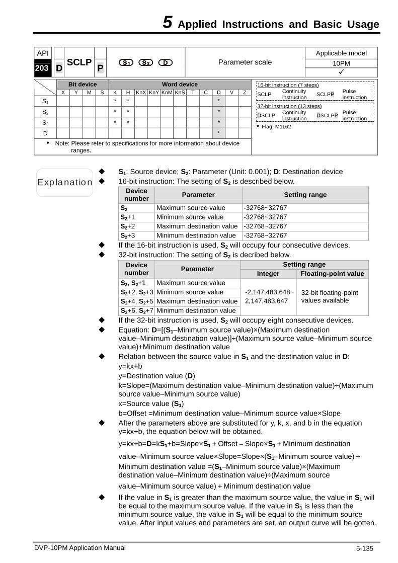
5 Applied Instructions and Basic Usage
API Applicable model 10PM 203
D SCLP P Parameter scale
Bit device Word device
X Y M S K H KnX KnY KnM KnS T C D V Z
S1 * * * S2 * * * S3 * * * D * Note: Please refer to specifications for more information about device
ranges.
16-bit instruction (7 steps) SCLP Continuity
instruction SCLPP Pulse instruction
32-bit instruction (13 steps) DSCLP Continuity
instruction DSCLPP Pulse instruction
Flag: M1162
Exp lanat ion 16-bit instruction: The setting of S2 is described below.
S1: Source device; S2: Parameter (Unit: 0.001); D: Destination device
Device number Parameter Setting range
S2 Maximum source value -32768~32767 S2+1 Minimum source value -32768~32767 S2+2 Maximum destination value -32768~32767 S2+3 Minimum destination value -32768~32767
If the 16-bit instruction is used, S2 will occupy four consecutive devices. 32-bit instruction: The setting of S2 is decribed below.
Setting range Device number Parameter
Integer Floating-point valueS2, S2+1 Maximum source value S2+2, S2+3 Minimum source value S2+4, S2+5 Maximum destination valueS2+6, S2+7 Minimum destination value
-2,147,483,648~ 2,147,483,647
32-bit floating-point values available
If the 32-bit instruction is used, S2 will occupy eight consecutive devices. Equation: D=[(S1–Minimum source value)×(Maximum destination
value–Minimum destination value)]÷(Maximum source value–Minimum source value)+Minimum destination value
Relation between the source value in S1 and the destination value in D: y=kx+b y=Destination value (D) k=Slope=(Maximum destination value–Minimum destination value)÷(Maximum source value–Minimum source value) x=Source value (S1) b=Offset =Minimum destination value–Minimum source value×Slope
After the parameters above are substituted for y, k, x, and b in the equation y=kx+b, the equation below will be obtained.
y=kx+b=D=kS1+b=Slope×S1+Offset=Slope×S1+Minimum destination
value–Minimum source value×Slope=Slope×(S1–Minimum source value)+Minimum destination value =(S1–Minimum source value)×(Maximum destination value–Minimum destination value)÷(Maximum source value–Minimum source value)+Minimum destination value
If the value in S1 is greater than the maximum source value, the value in S1 will be equal to the maximum source value. If the value in S1 is less than the minimum source value, the value in S1 will be equal to the minimum source value. After input values and parameters are set, an output curve will be gotten.
DVP-10PM Application Manual 5-135
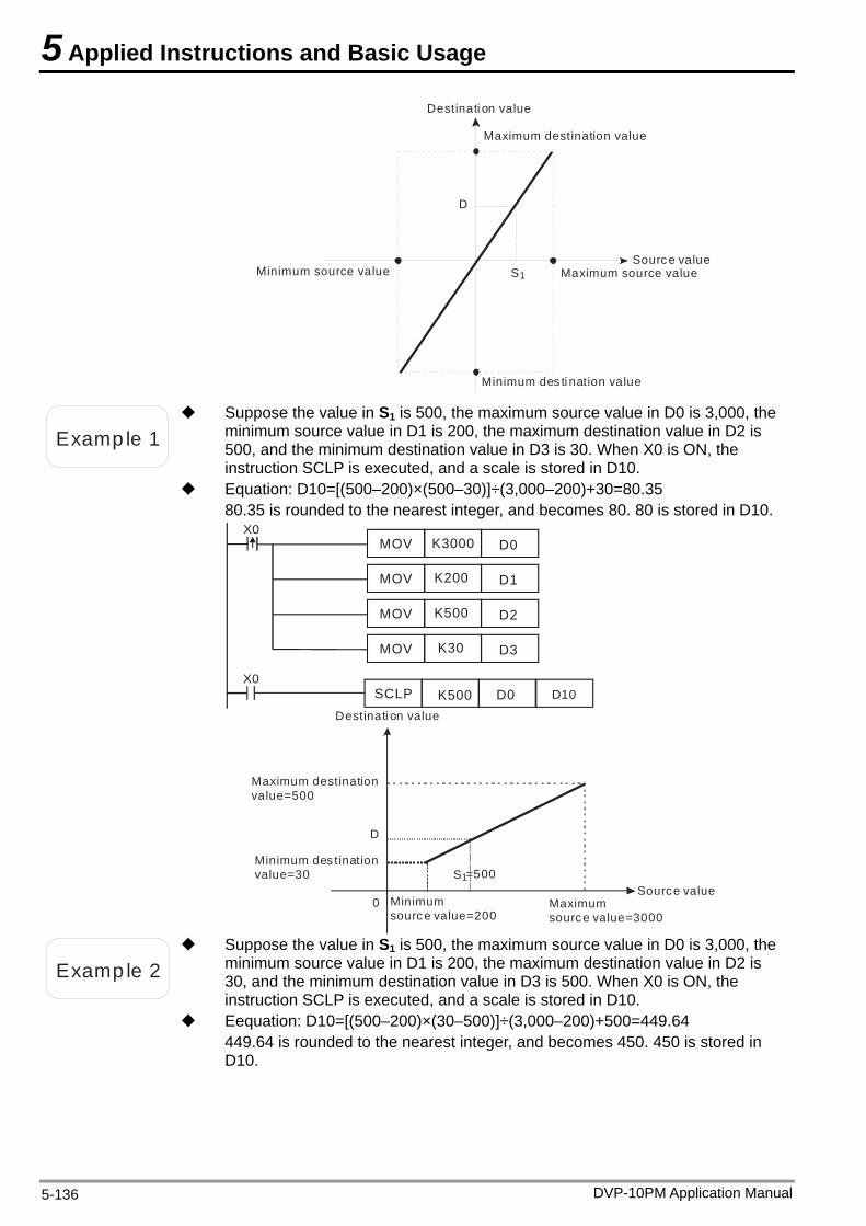
5 Applied Instructions and Basic Usage
D
S1Sourc e value
Maximum source valueMinimum source value
Destinati on value
Maximum destination value
Minimum des ti nation value
Examp le 1
Suppose the value in S1 is 500, the maximum source value in D0 is 3,000, the minimum source value in D1 is 200, the maximum destination value in D2 is 500, and the minimum destination value in D3 is 30. When X0 is ON, the instruction SCLP is executed, and a scale is stored in D10.
Equation: D10=[(500–200)×(500–30)]÷(3,000–200)+30=80.35 80.35 is rounded to the nearest integer, and becomes 80. 80 is stored in D10.
X0SCLP K500 D0 D10
X0MOV
MOV
MOV
MOV
K3000
K200
K500
K30
D0
D1
D2
D3
Source valueMaximum source value=3000
Minimum source value=200
Destinati on value
Maximum destination value=500
Minimum des tination value=30
D
S1
0
=500
Examp le 2
Suppose the value in S1 is 500, the maximum source value in D0 is 3,000, the minimum source value in D1 is 200, the maximum destination value in D2 is 30, and the minimum destination value in D3 is 500. When X0 is ON, the instruction SCLP is executed, and a scale is stored in D10.
Eequation: D10=[(500–200)×(30–500)]÷(3,000–200)+500=449.64 449.64 is rounded to the nearest integer, and becomes 450. 450 is stored in D10.
DVP-10PM Application Manual 5-136
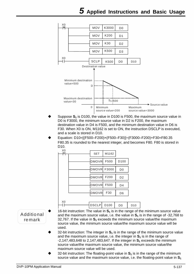
5 Applied Instructions and Basic Usage
X0SCLP K500 D0 D10
X0MOV
MOV
MOV
MOV
K3000
K200
K30
K500
D0
D1
D2
D3
Sourc e valueMaximum sourc e value=3000
Minimum sourc e value=200
Destinati on value
Maximum destination value=30
Minimum des tination value=500
S1=500
D
0
Suppose S1 is D100, the value in D100 is F500, the maximum source value in
D0 is F3000, the minimum source value in D2 is F200, the maximum destination value in D4 is F500, and the minimum destination value in D6 is F30. When X0 is ON, M1162 is set to ON, the instruction DSCLP is executed, and a scale is stored in D10.
Equation: D10=[(F500–F200)×(F500–F30)]÷(F3000–F200)+F30=F80.35 F80.35 is rounded to the nearest integer, and becomes F80. F80 is stored in D10.
X0DSCLP D100 D0 D10
X0
DMOVR
DMOVR
F3000
F200
F500
F500
F30
D0
D2
D4
D6
DMOVR
DMOVR
DMOVR
D100
SET M1162
Additional remark
16-bit instruction: The value in S1 is in the range of the minimum source value and the maximum source value, i.e. the value in S1 is in the range of -32,768 to32,767. If the value in S1 exceeds the minimum source value/the maximum source value, the minimum source value/the maximum source value will be used.
32-bit instruction: The integer in S1 is in the range of the minimum source value and the maximum source value, i.e. the integer in S1 is in the range of -2,147,483,648 to 2,147,483,647. If the integer in S1 exceeds the minimum source value/the maximum source value, the minimum source value/the maximum source value will be used.
32-bit instruction: The floating-point value in S1 is in the range of the minimum source value and the maximum source value, i.e. the floating-point value in S1
DVP-10PM Application Manual 5-137
5 Applied Instructions and Basic Usage
is a 32-bit floating-point value available. If the floating-point value in S1 exceeds the minimum source value/the maximum source value, the minimum source value/the maximum source value will be used.
If users use the instruction, the maximum source value must be greater than the minimum source value, and the maximum destination value does not have to be greater than the minimum destination value.
DVP-10PM Application Manual 5-138
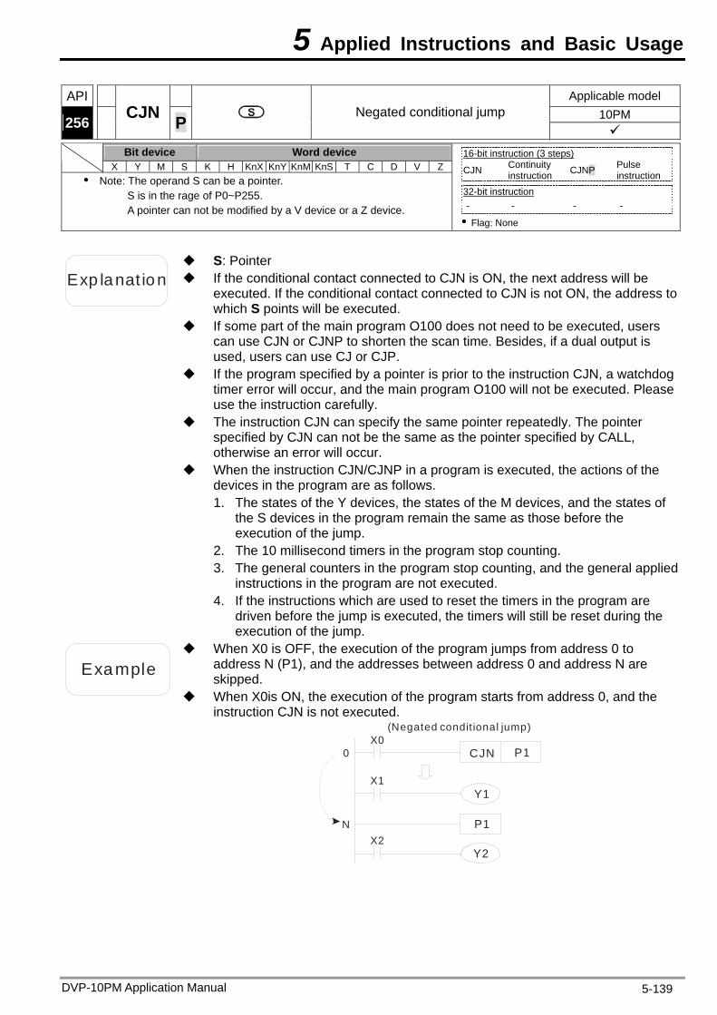
5 Applied Instructions and Basic Usage
API Applicable model 10PM 256
CJN Negated conditional jump P
Bit device Word device X Y M S K H KnX KnY KnM KnS T C D V Z
Note: The operand S can be a pointer. S is in the rage of P0~P255. A pointer can not be modified by a V device or a Z device.
16-bit instruction (3 steps) CJN Continuity
instruction CJNP Pulse instruction
32-bit instruction - - - -
Flag: None
Exp lanat ion If the conditional contact connected to CJN is ON, the next address will be executed. If the conditional contact connected to CJN is not ON, the address to which S points will be executed.
S: Pointer
If some part of the main program O100 does not need to be executed, users can use CJN or CJNP to shorten the scan time. Besides, if a dual output is used, users can use CJ or CJP.
If the program specified by a pointer is prior to the instruction CJN, a watchdog timer error will occur, and the main program O100 will not be executed. Please use the instruction carefully.
The instruction CJN can specify the same pointer repeatedly. The pointer specified by CJN can not be the same as the pointer specified by CALL, otherwise an error will occur.
When the instruction CJN/CJNP in a program is executed, the actions of the devices in the program are as follows. 1. The states of the Y devices, the states of the M devices, and the states of
the S devices in the program remain the same as those before the execution of the jump.
2. The 10 millisecond timers in the program stop counting. 3. The general counters in the program stop counting, and the general applied
instructions in the program are not executed. 4. If the instructions which are used to reset the timers in the program are
driven before the jump is executed, the timers will still be reset during the execution of the jump.
Example
When X0 is OFF, the execution of the program jumps from address 0 to address N (P1), and the addresses between address 0 and address N are skipped.
When X0is ON, the execution of the program starts from address 0, and the instruction CJN is not executed.
(Negated conditional jump)X0
X1
X2
CJN P1
Y1
Y2
0
N P1
DVP-10PM Application Manual 5-139
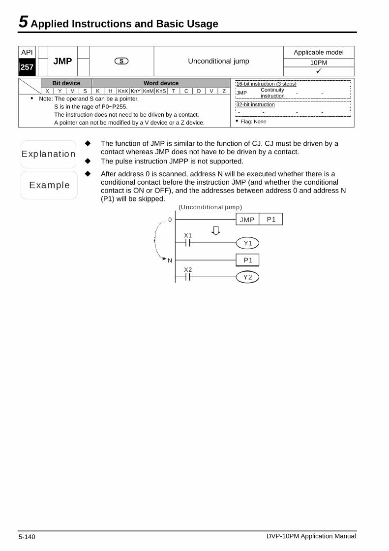
5 Applied Instructions and Basic Usage
API Applicable model 10PM 257
JMP Unconditional jump
Bit device Word device X Y M S K H KnX KnY KnM KnS T C D V Z
Note: The operand S can be a pointer. S is in the rage of P0~P255. The instruction does not need to be driven by a contact. A pointer can not be modified by a V device or a Z device.
16-bit instruction (3 steps) JMP Continuity
instruction - -
32-bit instruction - - - -
Flag: None
Exp lanat ion
The function of JMP is similar to the function of CJ. CJ must be driven by a contact whereas JMP does not have to be driven by a contact.
The pulse instruction JMPP is not supported.
Example
After address 0 is scanned, address N will be executed whether there is a conditional contact before the instruction JMP (and whether the conditional contact is ON or OFF), and the addresses between address 0 and address N (P1) will be skipped.
(Uncondit ional jump)
X1
X2
JMP P1
Y1
Y2
0
N P1
DVP-10PM Application Manual 5-140
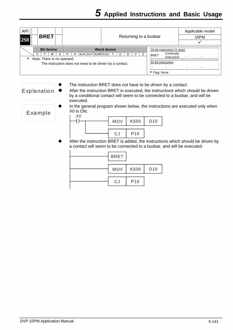
5 Applied Instructions and Basic Usage
API Applicable model 10PM 258 BRET Returning to a busbar
Bit device Word device
X Y M S K H KnX KnY KnM KnS T C D V Z Note: There is no operand.
The instruction does not need to be driven by a contact.
16-bit instruction (1 step) BRET Continuity
instruction - -
32-bit instruction - - - -
Flag: None
Exp lanat ion After the instruction BRET is executed, the instructions which should be driven by a conditional contact will seem to be connected to a busbar, and will be executed.
The instruction BRET does not have to be driven by a contact.
Example
In the general program shown below, the instructions are executed only when X0 is ON.
X0MOV K500
CJ P10
D10
After the instruction BRET is added, the instructions which should be driven by
a contact will seem to be connected to a busbar, and will be executed.
MOV K500
CJ P10
D10
BRET
DVP-10PM Application Manual 5-141
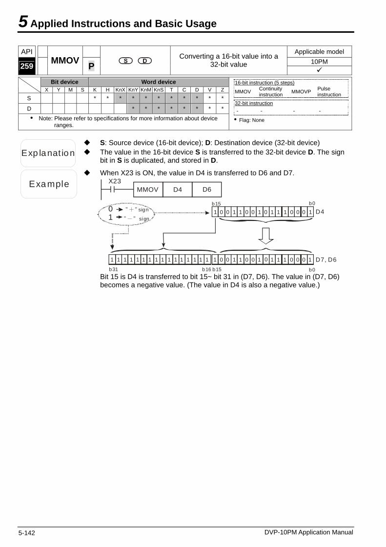
5 Applied Instructions and Basic Usage
DVP-10PM Application Manual 5-142
API Applicable model 10PM 259 MMOV P
Converting a 16-bit value into a 32-bit value
Bit device Word device
X Y M S K H KnX KnY KnM KnS T C D V Z
S * * * * * * * * * * *
D * * * * * * * *
Note: Please refer to specifications for more information about device ranges.
16-bit instruction (5 steps) MMOV Continuity
instruction MMOVP Pulse instruction
32-bit instruction - - - -
Flag: None
Exp lanat ion The value in the 16-bit device S is transferred to the 32-bit device D. The sign bit in S is duplicated, and stored in D.
S: Source device (16-bit device); D: Destination device (32-bit device)
Example
When X23 is ON, the value in D4 is transferred to D6 and D7. X23
MMOV D4 D6
0 0 1 1 1
0
0
0
1 1
1
10 0 0b15 b0
0 0 0 0 0 1111 D7, D6
1
11111111
b31 b16
1
b0b15
D4
0
1
1
00
111111111
" " + sign01
" " - sign
Bit 15 is D4 is transferred to bit 15~ bit 31 in (D7, D6). The value in (D7, D6) becomes a negative value. (The value in D4 is also a negative value.)
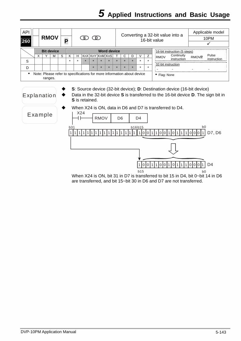
5 Applied Instructions and Basic Usage
DVP-10PM Application Manual 5-143
API Applicable model 10PM 260 RMOV P
Converting a 32-bit value into a 16-bit value
Bit device Word device
X Y M S K H KnX KnY KnM KnS T C D V Z
S * * * * * * * * * * *
D * * * * * * * *
Note: Please refer to specifications for more information about device ranges.
16-bit instruction (5 steps) RMOV Continuity
instruction RMOVP Pulse instruction
32-bit instruction - - - -
Flag: None
Exp lanat ion Data in the 32-bit device S is transferred to the 16-bit device D. The sign bit in S is retained.
S: Source device (32-bit device); D: Destination device (16-bit device)
Example
When X24 is ON, data in D6 and D7 is transferred to D4. X24
RMOV D6 D4
0 0 1 1 1
0
0
0
1 1
1
10 0 0b15 b0
0 0 0 0 0 1111
D7, D61
1
1111111b31 b161
b0b15
D40
1
1
00
1
11111111
When X24 is ON, bit 31 in D7 is transferred to bit 15 in D4, bit 0~bit 14 in D6 are transferred, and bit 15~bit 30 in D6 and D7 are not transferred.
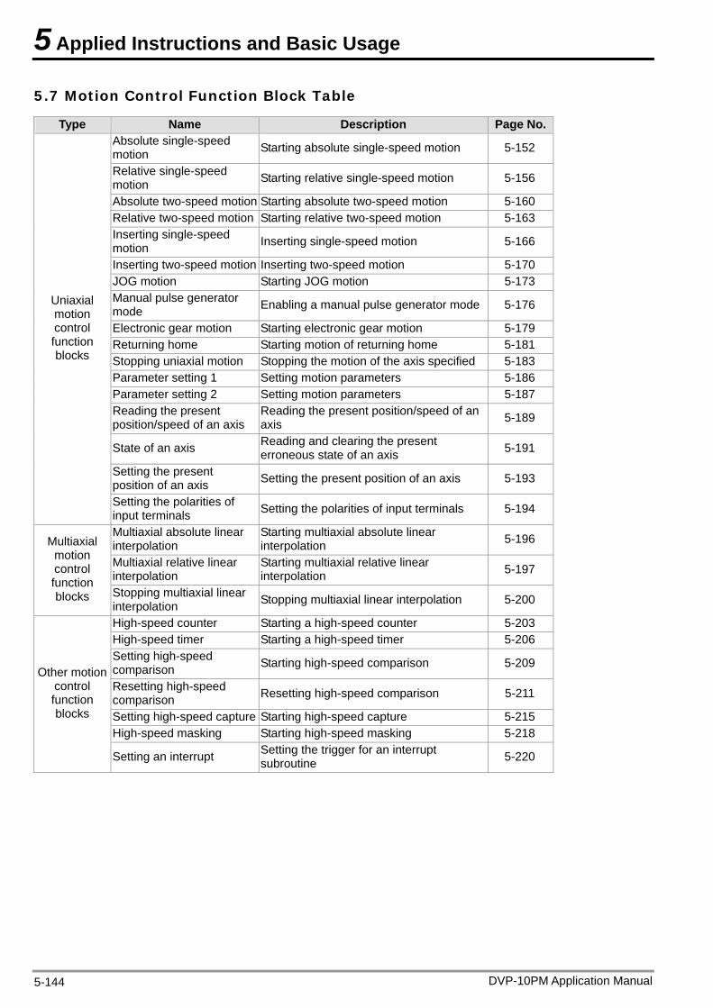
5 Applied Instructions and Basic Usage
5.7 Motion Control Function Block Table
Type Name Description Page No. Absolute single-speed motion Starting absolute single-speed motion 5-152
Relative single-speed motion Starting relative single-speed motion 5-156
Absolute two-speed motion Starting absolute two-speed motion 5-160 Relative two-speed motion Starting relative two-speed motion 5-163 Inserting single-speed motion Inserting single-speed motion 5-166
Inserting two-speed motion Inserting two-speed motion 5-170 JOG motion Starting JOG motion 5-173 Manual pulse generator mode Enabling a manual pulse generator mode 5-176
Electronic gear motion Starting electronic gear motion 5-179 Returning home Starting motion of returning home 5-181 Stopping uniaxial motion Stopping the motion of the axis specified 5-183 Parameter setting 1 Setting motion parameters 5-186 Parameter setting 2 Setting motion parameters 5-187 Reading the present position/speed of an axis
Reading the present position/speed of an axis 5-189
State of an axis Reading and clearing the present erroneous state of an axis 5-191
Setting the present position of an axis Setting the present position of an axis 5-193
Uniaxial motion control function blocks
Setting the polarities of input terminals Setting the polarities of input terminals 5-194
Multiaxial absolute linear interpolation
Starting multiaxial absolute linear interpolation 5-196
Multiaxial relative linear interpolation
Starting multiaxial relative linear interpolation 5-197
Multiaxial motion control function blocks Stopping multiaxial linear
interpolation Stopping multiaxial linear interpolation 5-200
High-speed counter Starting a high-speed counter 5-203 High-speed timer Starting a high-speed timer 5-206 Setting high-speed comparison Starting high-speed comparison 5-209
Resetting high-speed comparison Resetting high-speed comparison 5-211
Setting high-speed capture Starting high-speed capture 5-215 High-speed masking Starting high-speed masking 5-218
Other motion control function blocks
Setting an interrupt Setting the trigger for an interrupt subroutine 5-220
DVP-10PM Application Manual 5-144
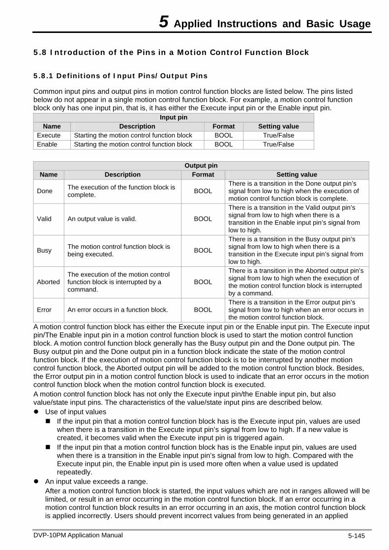
5 Applied Instructions and Basic Usage
5.8 Introduction of the Pins in a Motion Control Function Block
5.8.1 Definitions of Input Pins/Output Pins
Common input pins and output pins in motion control function blocks are listed below. The pins listed below do not appear in a single motion control function block. For example, a motion control function block only has one input pin, that is, it has either the Execute input pin or the Enable input pin.
Input pin Name Description Format Setting value
Execute Starting the motion control function block BOOL True/False Enable Starting the motion control function block BOOL True/False
Output pin
Name Description Format Setting value
Done The execution of the function block is complete. BOOL
There is a transition in the Done output pin’s signal from low to high when the execution of motion control function block is complete.
Valid An output value is valid. BOOL
There is a transition in the Valid output pin’s signal from low to high when there is a transition in the Enable input pin’s signal from low to high.
Busy The motion control function block is being executed. BOOL
There is a transition in the Busy output pin’s signal from low to high when there is a transition in the Execute input pin’s signal from low to high.
Aborted The execution of the motion control function block is interrupted by a command.
BOOL
There is a transition in the Aborted output pin’s signal from low to high when the execution of the motion control function block is interrupted by a command.
Error An error occurs in a function block. BOOL There is a transition in the Error output pin’s signal from low to high when an error occurs in the motion control function block.
A motion control function block has either the Execute input pin or the Enable input pin. The Execute input pin/The Enable input pin in a motion control function block is used to start the motion control function block. A motion control function block generally has the Busy output pin and the Done output pin. The Busy output pin and the Done output pin in a function block indicate the state of the motion control function block. If the execution of motion control function block is to be interrupted by another motion control function block, the Aborted output pin will be added to the motion control function block. Besides, the Error output pin in a motion control function block is used to indicate that an error occurs in the motion control function block when the motion control function block is executed. A motion control function block has not only the Execute input pin/the Enable input pin, but also value/state input pins. The characteristics of the value/state input pins are described below. Use of input values If the input pin that a motion control function block has is the Execute input pin, values are used
when there is a transition in the Execute input pin’s signal from low to high. If a new value is created, it becomes valid when the Execute input pin is triggered again.
If the input pin that a motion control function block has is the Enable input pin, values are used when there is a transition in the Enable input pin’s signal from low to high. Compared with the Execute input pin, the Enable input pin is used more often when a value used is updated repeatedly.
An input value exceeds a range. After a motion control function block is started, the input values which are not in ranges allowed will be limited, or result in an error occurring in the motion control function block. If an error occurring in a motion control function block results in an error occurring in an axis, the motion control function block is applied incorrectly. Users should prevent incorrect values from being generated in an applied
DVP-10PM Application Manual 5-145
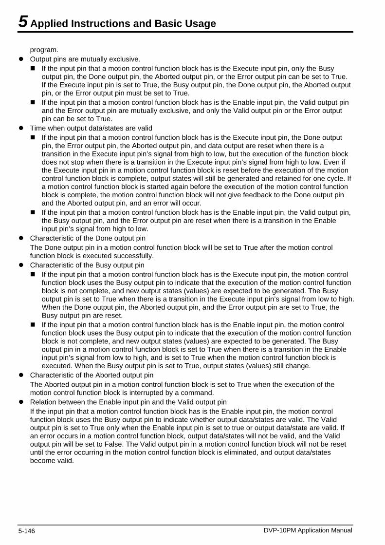
5 Applied Instructions and Basic Usage
program. Output pins are mutually exclusive. If the input pin that a motion control function block has is the Execute input pin, only the Busy
output pin, the Done output pin, the Aborted output pin, or the Error output pin can be set to True. If the Execute input pin is set to True, the Busy output pin, the Done output pin, the Aborted output pin, or the Error output pin must be set to True.
If the input pin that a motion control function block has is the Enable input pin, the Valid output pin and the Error output pin are mutually exclusive, and only the Valid output pin or the Error output pin can be set to True.
Time when output data/states are valid If the input pin that a motion control function block has is the Execute input pin, the Done output
pin, the Error output pin, the Aborted output pin, and data output are reset when there is a transition in the Execute input pin’s signal from high to low, but the execution of the function block does not stop when there is a transition in the Execute input pin’s signal from high to low. Even if the Execute input pin in a motion control function block is reset before the execution of the motion control function block is complete, output states will still be generated and retained for one cycle. If a motion control function block is started again before the execution of the motion control function block is complete, the motion control function block will not give feedback to the Done output pin and the Aborted output pin, and an error will occur.
If the input pin that a motion control function block has is the Enable input pin, the Valid output pin, the Busy output pin, and the Error output pin are reset when there is a transition in the Enable input pin’s signal from high to low.
Characteristic of the Done output pin The Done output pin in a motion control function block will be set to True after the motion control function block is executed successfully.
Characteristic of the Busy output pin If the input pin that a motion control function block has is the Execute input pin, the motion control
function block uses the Busy output pin to indicate that the execution of the motion control function block is not complete, and new output states (values) are expected to be generated. The Busy output pin is set to True when there is a transition in the Execute input pin’s signal from low to high. When the Done output pin, the Aborted output pin, and the Error output pin are set to True, the Busy output pin are reset.
If the input pin that a motion control function block has is the Enable input pin, the motion control function block uses the Busy output pin to indicate that the execution of the motion control function block is not complete, and new output states (values) are expected to be generated. The Busy output pin in a motion control function block is set to True when there is a transition in the Enable input pin’s signal from low to high, and is set to True when the motion control function block is executed. When the Busy output pin is set to True, output states (values) still change.
Characteristic of the Aborted output pin The Aborted output pin in a motion control function block is set to True when the execution of the motion control function block is interrupted by a command.
Relation between the Enable input pin and the Valid output pin If the input pin that a motion control function block has is the Enable input pin, the motion control function block uses the Busy output pin to indicate whether output data/states are valid. The Valid output pin is set to True only when the Enable input pin is set to true or output data/state are valid. If an error occurs in a motion control function block, output data/states will not be valid, and the Valid output pin will be set to False. The Valid output pin in a motion control function block will not be reset until the error occurring in the motion control function block is eliminated, and output data/states become valid.
DVP-10PM Application Manual 5-146
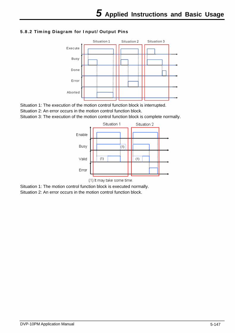
5 Applied Instructions and Basic Usage
5.8.2 Timing Diagram for Input/Output Pins
Aborted
Er ror
Done
Busy
Execute
Situation 1 Situation 2 Situation 3
Situation 1: The execution of the motion control function block is interrupted. Situation 2: An error occurs in the motion control function block. Situation 3: The execution of the motion control function block is complete normally.
Situation 1: The motion control function block is executed normally. Situation 2: An error occurs in the motion control function block.
DVP-10PM Application Manual 5-147
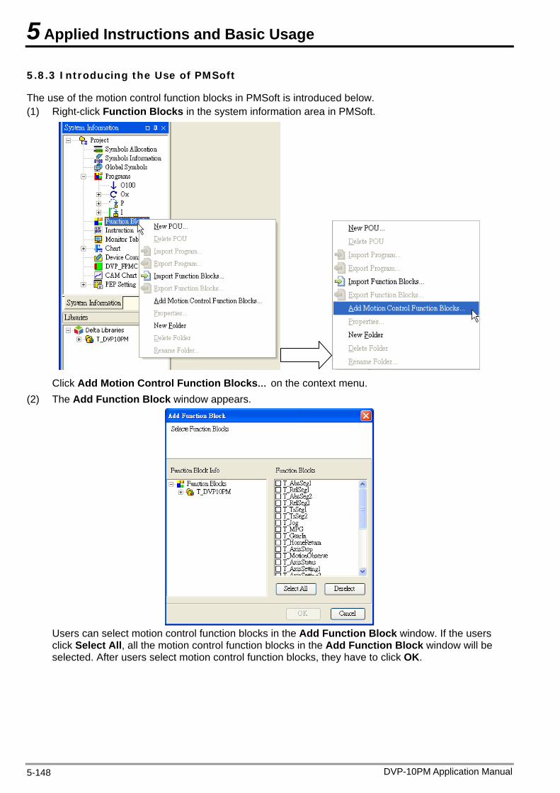
5 Applied Instructions and Basic Usage
5.8.3 Introducing the Use of PMSoft
The use of the motion control function blocks in PMSoft is introduced below. (1) Right-click Function Blocks in the system information area in PMSoft.
Click Add Motion Control Function Blocks… on the context menu.
(2) The Add Function Block window appears.
Users can select motion control function blocks in the Add Function Block window. If the users click Select All, all the motion control function blocks in the Add Function Block window will be selected. After users select motion control function blocks, they have to click OK.
DVP-10PM Application Manual 5-148
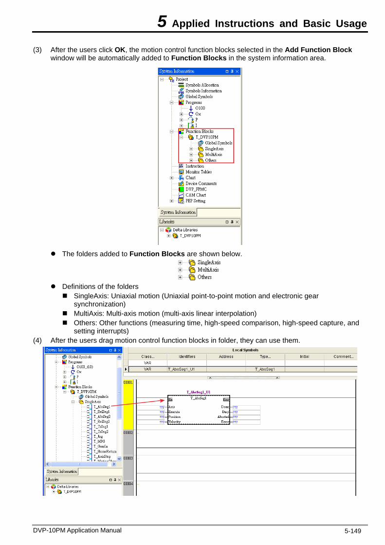
5 Applied Instructions and Basic Usage
(3) After the users click OK, the motion control function blocks selected in the Add Function Block window will be automatically added to Function Blocks in the system information area.
The folders added to Function Blocks are shown below.
Definitions of the folders SingleAxis: Uniaxial motion (Uniaxial point-to-point motion and electronic gear
synchronization) MultiAxis: Multi-axis motion (multi-axis linear interpolation) Others: Other functions (measuring time, high-speed comparison, high-speed capture, and
setting interrupts) (4) After the users drag motion control function blocks in folder, they can use them.
DVP-10PM Application Manual 5-149
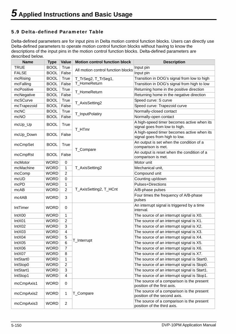
5 Applied Instructions and Basic Usage
5.9 Delta-defined Parameter Table
Delta-defined parameters are for input pins in Delta motion control function blocks. Users can directly use Delta-defined parameters to operate motion control function blocks without having to know the descriptions of the input pins in the motion control function blocks. Delta-defined parameters are described below.
Name Type Value Motion control function block Description TRUE BOOL True Input pin FALSE BOOL False
All motion control function blocksInput pin
mcRising BOOL True Transition in DOG’s signal from low to high mcFalling BOOL False
T_TrSeg2, T_TrSeg1, T_HomeReturn Transition in DOG’s signal from high to low
mcPositive BOOL True Returning home in the positive direction mcNegative BOOL False
T_HomeReturn Returning home in the negative direction
mcSCurve BOOL True Speed curve: S curve mcTrapezoid BOOL False
T_AxisSetting2 Speed curve: Trapezoid curve
mcNC BOOL True Normally-closed contact mcNO BOOL False
T_InputPolatiry Normally-open contact
mcUp_Up BOOL True A high-speed timer becomes active when its signal goes from low to high.
mcUp_Down BOOL FalseT_HTmr
A high-speed timer becomes active when its signal goes from high to low.
mcCmpSet BOOL True An output is set when the condition of a comparison is met.
mcCmpRst BOOL FalseT_Compare
An output is reset when the condition of a comparison is met.
mcMotor WORD 0 Motor unit mcMachine WORD 1 Mechanical unit, mcComp WORD 2
T_AxisSetting2 Compound unit
mcUD WORD 0 Counting up/down mcPD WORD 1 Pulses+Directions mcAB WORD 2 A/B-phase pulses
mc4AB WORD 3
T_AxisSetting2, T_HCnt Four times the frequency of A/B-phase pulses
IntTimer WORD 0 An interrupt signal is triggered by a time interval.
IntX00 WORD 1 The source of an interrupt signal is X0. IntX01 WORD 2 The source of an interrupt signal is X1. IntX02 WORD 3 The source of an interrupt signal is X2. IntX03 WORD 4 The source of an interrupt signal is X3. IntX04 WORD 5 The source of an interrupt signal is X4. IntX05 WORD 6 The source of an interrupt signal is X5. IntX06 WORD 7 The source of an interrupt signal is X6. IntX07 WORD 8 The source of an interrupt signal is X7. IntStart0 WORD 1 The source of an interrupt signal is Start0. IntStop0 WORD 2 The source of an interrupt signal is Stop0. IntStart1 WORD 3 The source of an interrupt signal is Start1. IntStop1 WORD 4
T_Interrupt
The source of an interrupt signal is Stop1.
mcCmpAxis1 WORD 0 The source of a comparison is the present position of the first axis.
mcCmpAxis2 WORD 1 The source of a comparison is the present position of the second axis.
mcCmpAxis3 WORD 2
T_Compare
The source of a comparison is the present position of the third axis.
DVP-10PM Application Manual 5-150
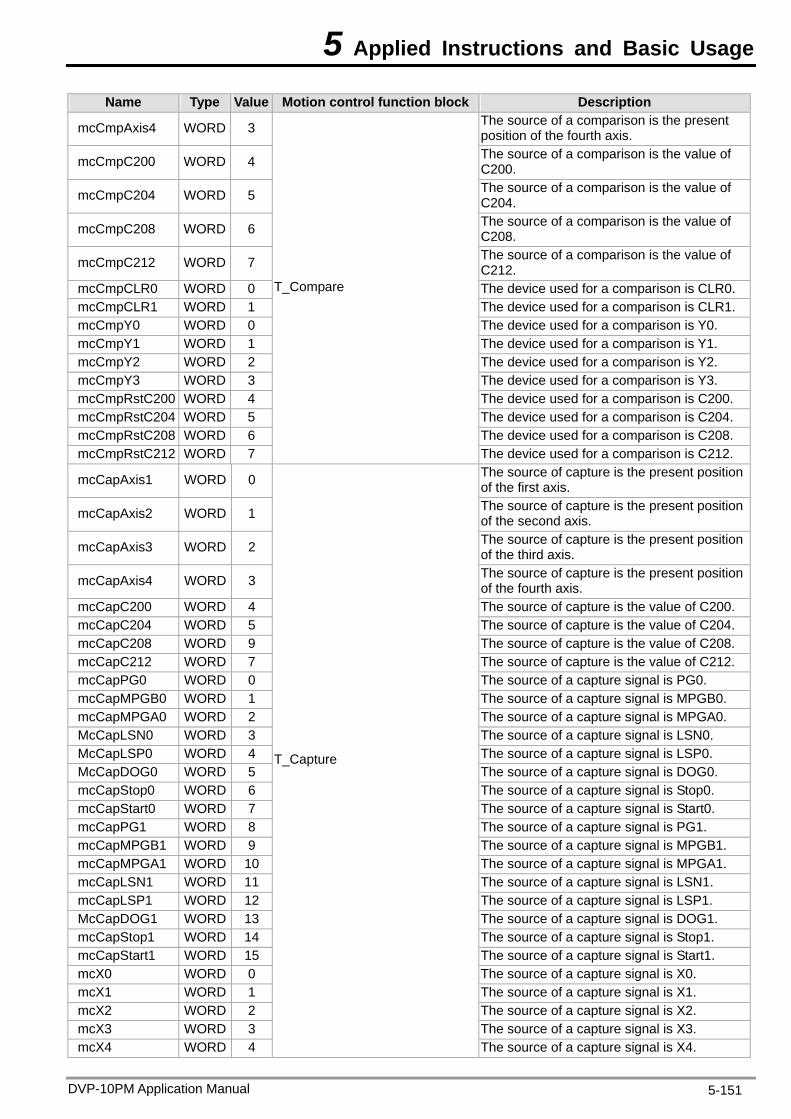
5 Applied Instructions and Basic Usage
DVP-10PM Application Manual 5-151
Name Type Value Motion control function block Description
mcCmpAxis4 WORD 3 The source of a comparison is the present position of the fourth axis.
mcCmpC200 WORD 4 The source of a comparison is the value of C200.
mcCmpC204 WORD 5 The source of a comparison is the value of C204.
mcCmpC208 WORD 6 The source of a comparison is the value of C208.
mcCmpC212 WORD 7 The source of a comparison is the value of C212.
mcCmpCLR0 WORD 0 The device used for a comparison is CLR0. mcCmpCLR1 WORD 1 The device used for a comparison is CLR1. mcCmpY0 WORD 0 The device used for a comparison is Y0. mcCmpY1 WORD 1 The device used for a comparison is Y1. mcCmpY2 WORD 2 The device used for a comparison is Y2. mcCmpY3 WORD 3 The device used for a comparison is Y3. mcCmpRstC200 WORD 4 The device used for a comparison is C200. mcCmpRstC204 WORD 5 The device used for a comparison is C204. mcCmpRstC208 WORD 6 The device used for a comparison is C208. mcCmpRstC212 WORD 7
T_Compare
The device used for a comparison is C212.
mcCapAxis1 WORD 0 The source of capture is the present position of the first axis.
mcCapAxis2 WORD 1 The source of capture is the present position of the second axis.
mcCapAxis3 WORD 2 The source of capture is the present position of the third axis.
mcCapAxis4 WORD 3 The source of capture is the present position of the fourth axis.
mcCapC200 WORD 4 The source of capture is the value of C200. mcCapC204 WORD 5 The source of capture is the value of C204. mcCapC208 WORD 9 The source of capture is the value of C208. mcCapC212 WORD 7 The source of capture is the value of C212. mcCapPG0 WORD 0 The source of a capture signal is PG0. mcCapMPGB0 WORD 1 The source of a capture signal is MPGB0. mcCapMPGA0 WORD 2 The source of a capture signal is MPGA0. McCapLSN0 WORD 3 The source of a capture signal is LSN0. McCapLSP0 WORD 4 The source of a capture signal is LSP0. McCapDOG0 WORD 5 The source of a capture signal is DOG0. mcCapStop0 WORD 6 The source of a capture signal is Stop0. mcCapStart0 WORD 7 The source of a capture signal is Start0. mcCapPG1 WORD 8 The source of a capture signal is PG1. mcCapMPGB1 WORD 9 The source of a capture signal is MPGB1. mcCapMPGA1 WORD 10 The source of a capture signal is MPGA1. mcCapLSN1 WORD 11 The source of a capture signal is LSN1. mcCapLSP1 WORD 12 The source of a capture signal is LSP1. McCapDOG1 WORD 13 The source of a capture signal is DOG1. mcCapStop1 WORD 14 The source of a capture signal is Stop1. mcCapStart1 WORD 15 The source of a capture signal is Start1. mcX0 WORD 0 The source of a capture signal is X0. mcX1 WORD 1 The source of a capture signal is X1. mcX2 WORD 2 The source of a capture signal is X2. mcX3 WORD 3 The source of a capture signal is X3. mcX4 WORD 4
T_Capture
The source of a capture signal is X4.
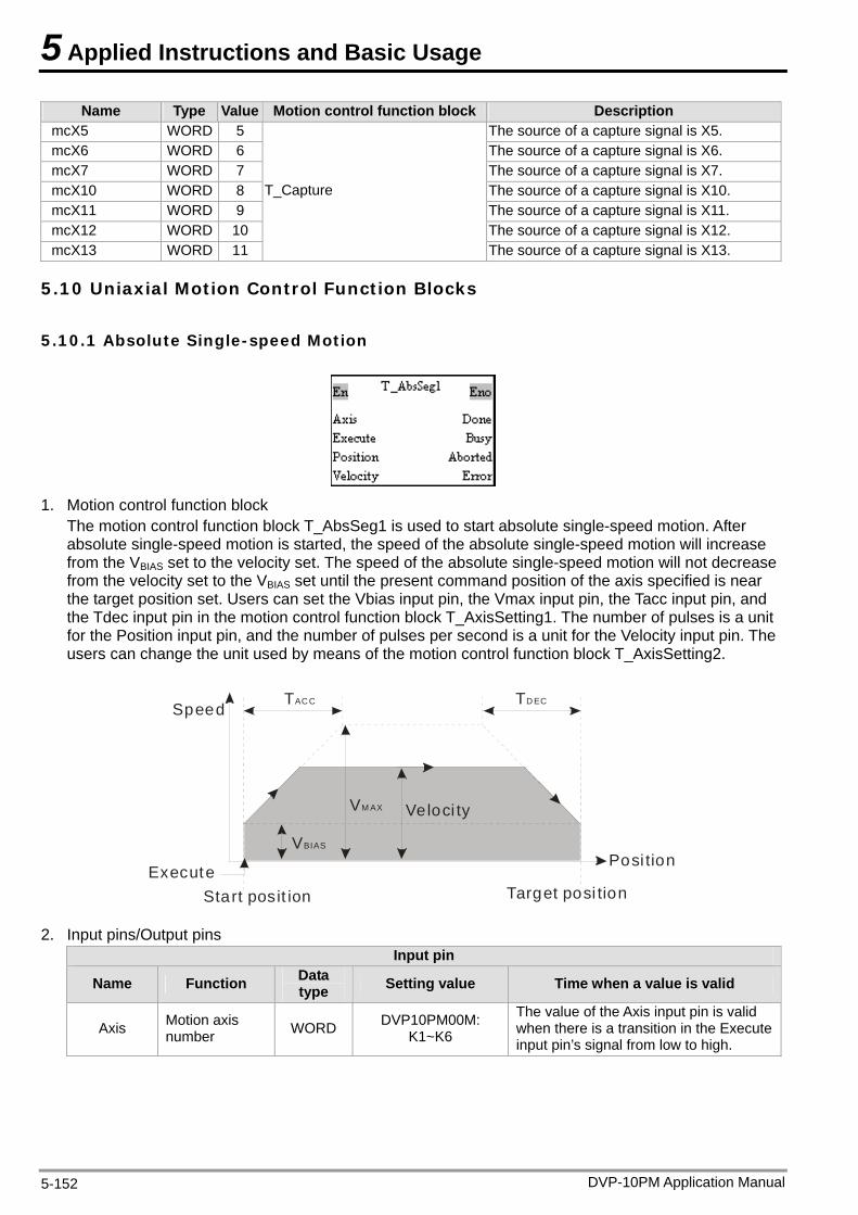
5 Applied Instructions and Basic Usage
DVP-10PM Application Manual 5-152
Name Type Value Motion control function block Description mcX5 WORD 5 The source of a capture signal is X5. mcX6 WORD 6 The source of a capture signal is X6. mcX7 WORD 7 The source of a capture signal is X7. mcX10 WORD 8 The source of a capture signal is X10. mcX11 WORD 9 The source of a capture signal is X11. mcX12 WORD 10 The source of a capture signal is X12. mcX13 WORD 11
T_Capture
The source of a capture signal is X13.
5.10 Uniaxial Motion Control Function Blocks
5.10.1 Absolute Single-speed Motion
1. Motion control function block
The motion control function block T_AbsSeg1 is used to start absolute single-speed motion. After absolute single-speed motion is started, the speed of the absolute single-speed motion will increase from the VBIAS set to the velocity set. The speed of the absolute single-speed motion will not decrease from the velocity set to the VBIAS set until the present command position of the axis specified is near the target position set. Users can set the Vbias input pin, the Vmax input pin, the Tacc input pin, and the Tdec input pin in the motion control function block T_AxisSetting1. The number of pulses is a unit for the Position input pin, and the number of pulses per second is a unit for the Velocity input pin. The users can change the unit used by means of the motion control function block T_AxisSetting2.
SpeedTAC C TD EC
VM AX
VBIAS
Execute
Veloci ty
Posi tion
Target posi tionStart posit ion
2. Input pins/Output pins Input pin
Name Function Data type Setting value Time when a value is valid
Axis Motion axis number WORD DVP10PM00M:
K1~K6
The value of the Axis input pin is valid when there is a transition in the Execute input pin’s signal from low to high.
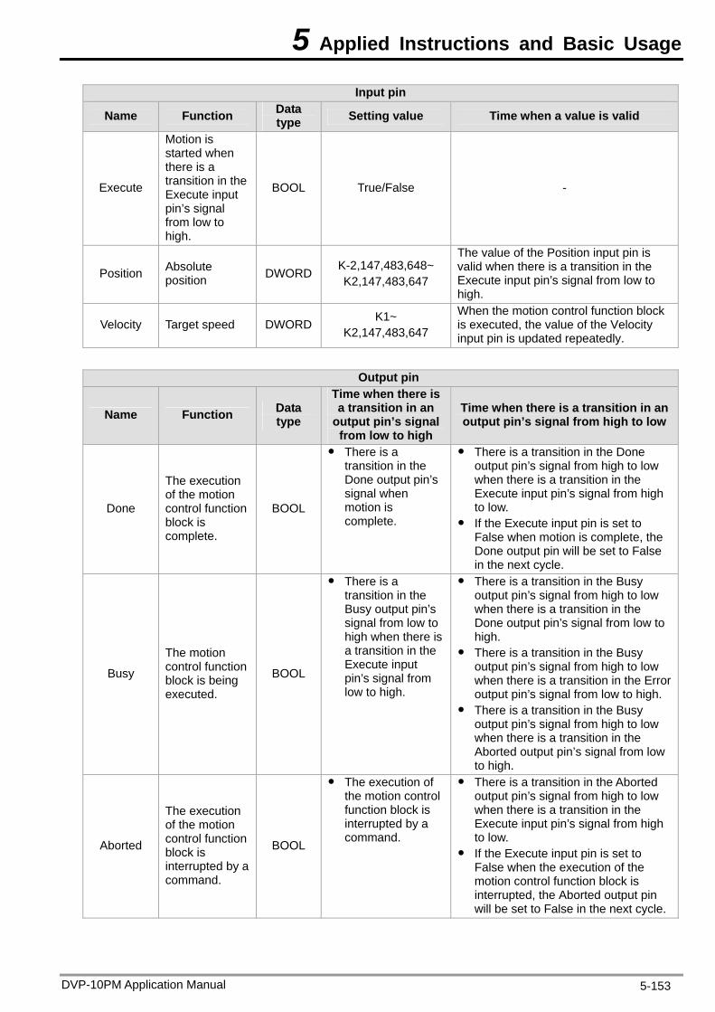
5 Applied Instructions and Basic Usage
DVP-10PM Application Manual 5-153
Input pin
Name Function Data type Setting value Time when a value is valid
Execute
Motion is started when there is a transition in the Execute input pin’s signal from low to high.
BOOL True/False -
Position Absolute position DWORD K-2,147,483,648~
K2,147,483,647
The value of the Position input pin is valid when there is a transition in the Execute input pin’s signal from low to high.
Velocity Target speed DWORD K1~ K2,147,483,647
When the motion control function block is executed, the value of the Velocity input pin is updated repeatedly.
Output pin
Name Function Data type
Time when there is a transition in an
output pin’s signal from low to high
Time when there is a transition in an output pin’s signal from high to low
Done
The execution of the motion control function block is complete.
BOOL
There is a transition in the Done output pin’s signal when motion is complete.
There is a transition in the Done output pin’s signal from high to low when there is a transition in the Execute input pin’s signal from high to low.
If the Execute input pin is set to False when motion is complete, the Done output pin will be set to False in the next cycle.
Busy
The motion control function block is being executed.
BOOL
There is a transition in the Busy output pin’s signal from low to high when there is a transition in the Execute input pin’s signal from low to high.
There is a transition in the Busy output pin’s signal from high to low when there is a transition in the Done output pin’s signal from low to high.
There is a transition in the Busy output pin’s signal from high to low when there is a transition in the Error output pin’s signal from low to high.
There is a transition in the Busy output pin’s signal from high to low when there is a transition in the Aborted output pin’s signal from low to high.
Aborted
The execution of the motion control function block is interrupted by a command.
BOOL
The execution of the motion control function block is interrupted by a command.
There is a transition in the Aborted output pin’s signal from high to low when there is a transition in the Execute input pin’s signal from high to low.
If the Execute input pin is set to False when the execution of the motion control function block is interrupted, the Aborted output pin will be set to False in the next cycle.
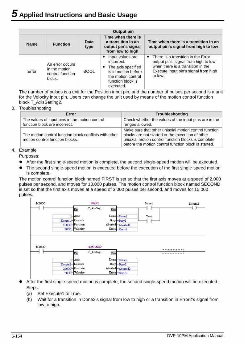
5 Applied Instructions and Basic Usage
DVP-10PM Application Manual 5-154
Output pin
Name Function Data type
Time when there is a transition in an
output pin’s signal from low to high
Time when there is a transition in an output pin’s signal from high to low
Error
An error occurs in the motion control function block.
BOOL
Input values are incorrect.
The axis specified is in motion before the motion control function block is executed.
There is a transition in the Error output pin’s signal from high to low when there is a transition in the Execute input pin’s signal from high to low.
The number of pulses is a unit for the Position input pin, and the number of pulses per second is a unit for the Velocity input pin. Users can change the unit used by means of the motion control function block T_AxisSetting2.
3. Troubleshooting Error Troubleshooting
The values of input pins in the motion control function block are incorrect.
Check whether the values of the input pins are in the ranges allowed.
The motion control function block conflicts with other motion control function blocks.
Make sure that other uniaxial motion control function blocks are not started or the execution of other uniaxial motion control function blocks is complete before the motion control function block is started.
4. Example Purposes: After the first single-speed motion is complete, the second single-speed motion will be executed. The second single-speed motion is executed before the execution of the first single-speed motion
is complete. The motion control function block named FIRST is set so that the first axis moves at a speed of 2,000 pulses per second, and moves for 10,000 pulses. The motion control function block named SECOND is set so that the first axis moves at a speed of 3,000 pulses per second, and moves for 15,000 pulses.
After the first single-speed motion is complete, the second single-speed motion will be executed.
Steps: (a) Set Execute1 to True. (b) Wait for a transition in Done2’s signal from low to high or a transition in Error2’s signal from
low to high.
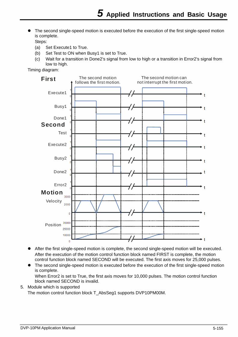
5 Applied Instructions and Basic Usage
The second single-speed motion is executed before the execution of the first single-speed motion is complete. Steps: (a) Set Execute1 to True. (b) Set Test to ON when Busy1 is set to True. (c) Wait for a transition in Done2’s signal from low to high or a transition in Error2’s signal from
low to high. Timing diagram:
The second motionfollows the first motion.
The second motion cannot interrupt the first motion.First
Execute1
Busy1
Done1
Second
Execute2
Busy2
Done2
Error2
Test
MotionVelocity
Position
After the first single-speed motion is complete, the second single-speed motion will be executed.
After the execution of the motion control function block named FIRST is complete, the motion control function block named SECOND will be executed. The first axis moves for 25,000 pulses.
The second single-speed motion is executed before the execution of the first single-speed motion is complete. When Error2 is set to True, the first axis moves for 10,000 pulses. The motion control function block named SECOND is invalid.
5. Module which is supported The motion control function block T_AbsSeg1 supports DVP10PM00M.
DVP-10PM Application Manual 5-155
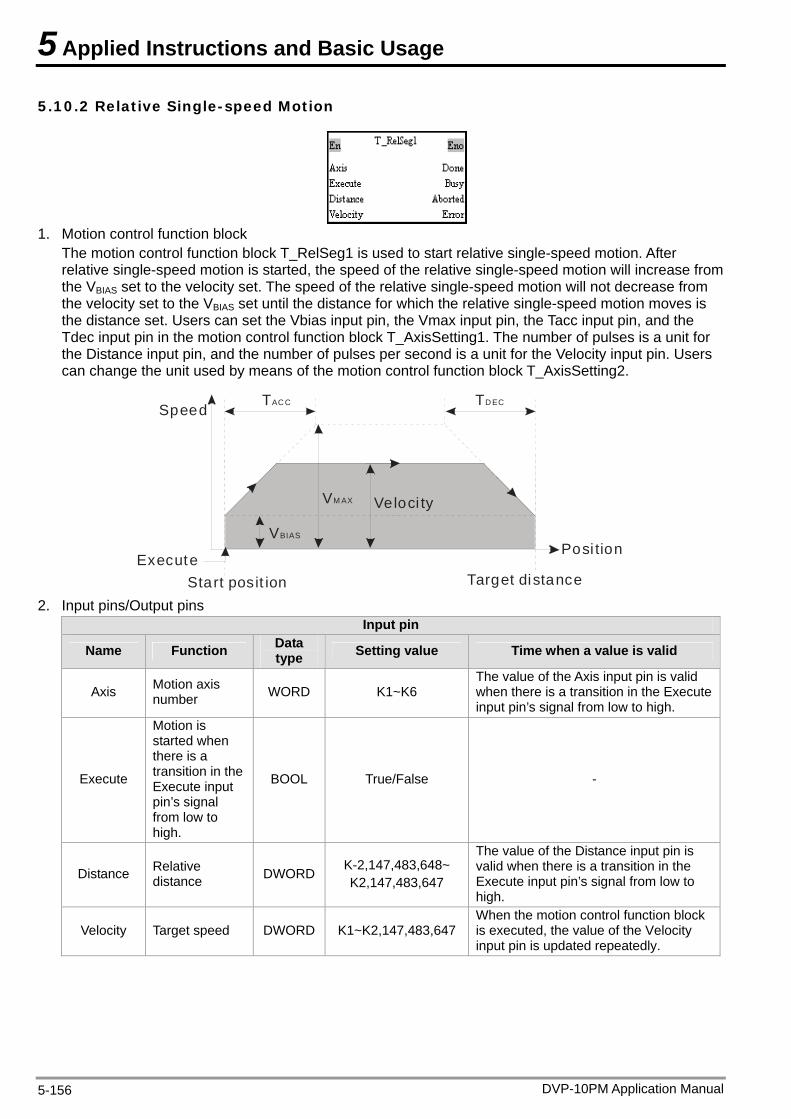
5 Applied Instructions and Basic Usage
5.10.2 Relative Single-speed Motion
1. Motion control function block
The motion control function block T_RelSeg1 is used to start relative single-speed motion. After relative single-speed motion is started, the speed of the relative single-speed motion will increase from the VBIAS set to the velocity set. The speed of the relative single-speed motion will not decrease from the velocity set to the VBIAS set until the distance for which the relative single-speed motion moves is the distance set. Users can set the Vbias input pin, the Vmax input pin, the Tacc input pin, and the Tdec input pin in the motion control function block T_AxisSetting1. The number of pulses is a unit for the Distance input pin, and the number of pulses per second is a unit for the Velocity input pin. Users can change the unit used by means of the motion control function block T_AxisSetting2.
SpeedTAC C TD EC
VM AX
VBIAS
Execute
Veloci ty
Posi tion
Target distanceStart posit ion 2. Input pins/Output pins
Input pin
Name Function Data type Setting value Time when a value is valid
Axis Motion axis number WORD K1~K6
The value of the Axis input pin is valid when there is a transition in the Execute input pin’s signal from low to high.
Execute
Motion is started when there is a transition in the Execute input pin’s signal from low to high.
BOOL True/False -
Distance Relative distance DWORD K-2,147,483,648~
K2,147,483,647
The value of the Distance input pin is valid when there is a transition in the Execute input pin’s signal from low to high.
Velocity Target speed DWORD K1~K2,147,483,647 When the motion control function block is executed, the value of the Velocity input pin is updated repeatedly.
DVP-10PM Application Manual 5-156

5 Applied Instructions and Basic Usage
Output pin
Name Function Data type
Time when there is a transition in an
output pin’s signal from low to high
Time when there is a transition in an output pin’s signal from high to low
Done
The execution of the motion control function block is complete.
BOOL
There is a transition in the Done output pin’s signal when motion is complete.
There is a transition in the Done output pin’s signal from high to low when there is a transition in the Execute input pin’s signal from high to low.
If the Execute input pin is set to False when motion is complete, the Done output pin will be set to False in the next cycle.
Busy
The motion control function block is being executed.
BOOL
There is a transition in the Busy output pin’s signal from low to high when there is a transition in the Execute input pin’s signal from low to high.
There is a transition in the Busy output pin’s signal from high to low when there is a transition in the Done output pin’s signal from low to high.
There is a transition in the Busy output pin’s signal from high to low when there is a transition in the Error output pin’s signal from low to high.
There is a transition in the Busy output pin’s signal from high to low when there is a transition in the Aborted output pin’s signal from low to high.
Aborted
The execution of the motion control function block is interrupted by a command.
BOOL
The execution of the motion control function block is interrupted by a command.
There is a transition in the Aborted output pin’s signal from high to low when there is a transition in the Execute input pin’s signal from high to low.
If the Execute input pin is set to False when the execution of the motion control function block is interrupted, the Aborted output pin will be set to False in the next cycle.
Error
An error occurs in the motion control function block.
BOOL
Input values are incorrect.
The axis specified is in motion before the motion control function block is executed.
There is a transition in the Error output pin’s signal from high to low when there is a transition in the Execute input pin’s signal from high to low.
The number of pulses is a unit for the Distance input pin, and the number of pulses per second is a unit for the Velocity input pin. Users can change the unit used by means of the motion control function block T_AxisSetting2.
3. Troubleshooting Error Troubleshooting
The values of input pins in the motion control function block are incorrect.
Check whether the values of the input pins are in the ranges allowed.
The motion control function block conflicts with other motion control function blocks.
Make sure that other uniaxial motion control function blocks are not started or the execution of other uniaxial motion control function blocks is complete before the motion control function block is started.
DVP-10PM Application Manual 5-157
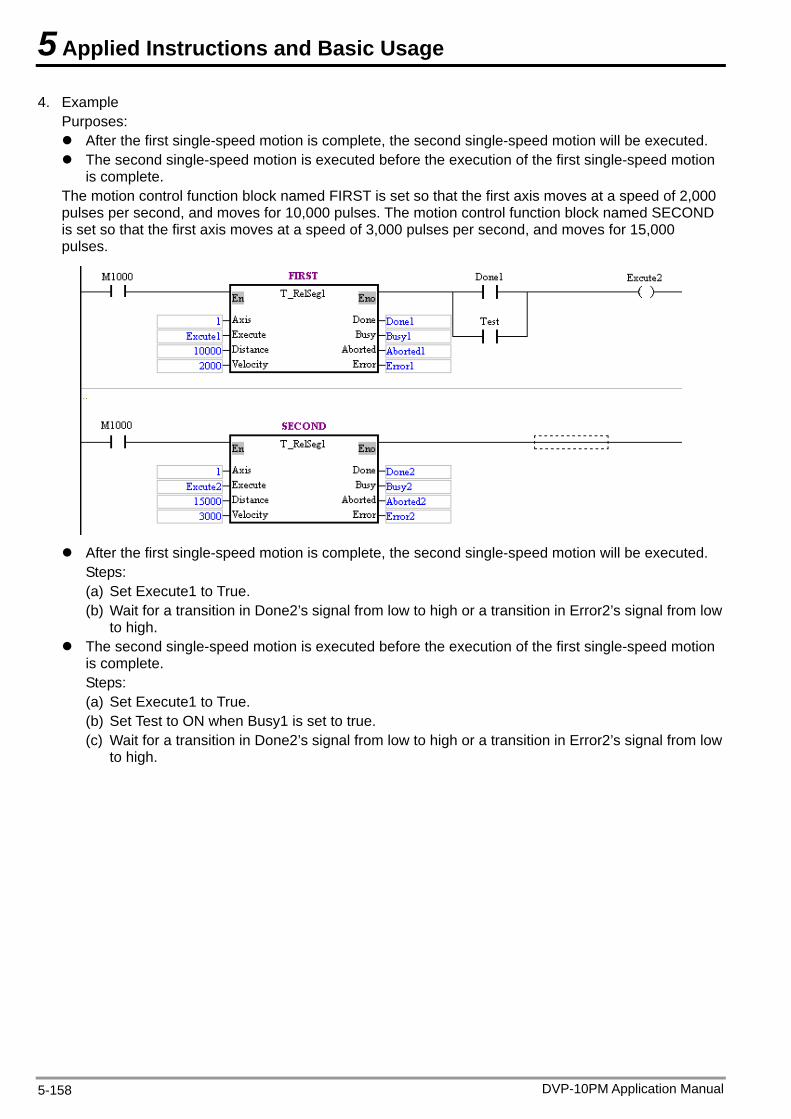
5 Applied Instructions and Basic Usage
4. Example Purposes: After the first single-speed motion is complete, the second single-speed motion will be executed. The second single-speed motion is executed before the execution of the first single-speed motion
is complete. The motion control function block named FIRST is set so that the first axis moves at a speed of 2,000 pulses per second, and moves for 10,000 pulses. The motion control function block named SECOND is set so that the first axis moves at a speed of 3,000 pulses per second, and moves for 15,000 pulses.
After the first single-speed motion is complete, the second single-speed motion will be executed.
Steps: (a) Set Execute1 to True. (b) Wait for a transition in Done2’s signal from low to high or a transition in Error2’s signal from low
to high. The second single-speed motion is executed before the execution of the first single-speed motion
is complete. Steps: (a) Set Execute1 to True. (b) Set Test to ON when Busy1 is set to true. (c) Wait for a transition in Done2’s signal from low to high or a transition in Error2’s signal from low
to high.
DVP-10PM Application Manual 5-158
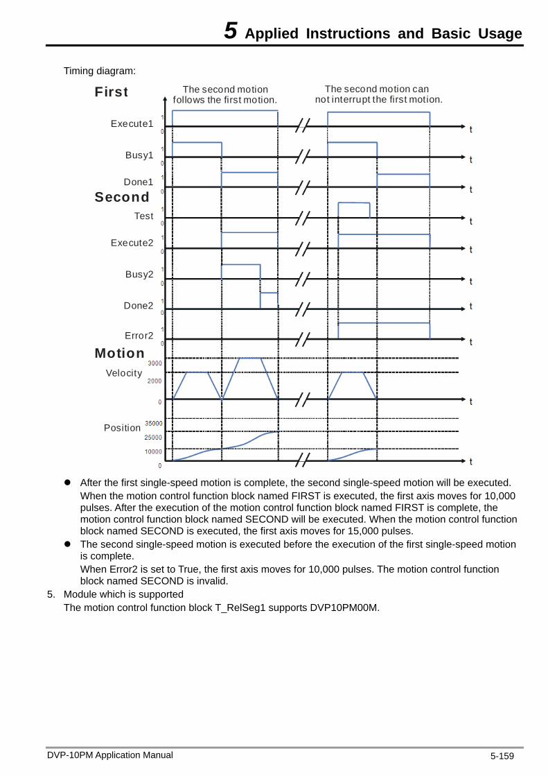
5 Applied Instructions and Basic Usage
Timing diagram:
The second motionfollows the first motion.
The second motion cannot interrupt the first motion.First
Execute1
Busy1
Done1
Second
Execute2
Busy2
Done2
Error2
Test
MotionVelocity
Position
After the first single-speed motion is complete, the second single-speed motion will be executed.
When the motion control function block named FIRST is executed, the first axis moves for 10,000 pulses. After the execution of the motion control function block named FIRST is complete, the motion control function block named SECOND will be executed. When the motion control function block named SECOND is executed, the first axis moves for 15,000 pulses.
The second single-speed motion is executed before the execution of the first single-speed motion is complete. When Error2 is set to True, the first axis moves for 10,000 pulses. The motion control function block named SECOND is invalid.
5. Module which is supported The motion control function block T_RelSeg1 supports DVP10PM00M.
DVP-10PM Application Manual 5-159
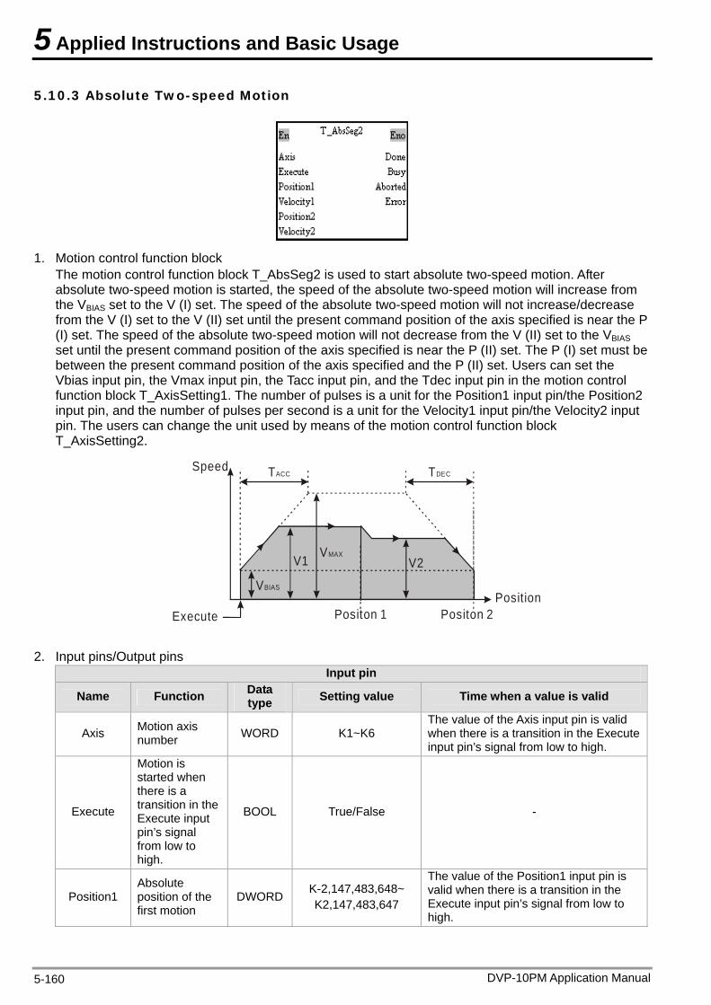
5 Applied Instructions and Basic Usage
5.10.3 Absolute Two-speed Motion
1. Motion control function block The motion control function block T_AbsSeg2 is used to start absolute two-speed motion. After absolute two-speed motion is started, the speed of the absolute two-speed motion will increase from the VBIAS set to the V (I) set. The speed of the absolute two-speed motion will not increase/decrease from the V (I) set to the V (II) set until the present command position of the axis specified is near the P (I) set. The speed of the absolute two-speed motion will not decrease from the V (II) set to the VBIAS set until the present command position of the axis specified is near the P (II) set. The P (I) set must be between the present command position of the axis specified and the P (II) set. Users can set the Vbias input pin, the Vmax input pin, the Tacc input pin, and the Tdec input pin in the motion control function block T_AxisSetting1. The number of pulses is a unit for the Position1 input pin/the Position2 input pin, and the number of pulses per second is a unit for the Velocity1 input pin/the Velocity2 input pin. The users can change the unit used by means of the motion control function block T_AxisSetting2.
Speed TACC TDEC
VMAX
PositionVBIAS
V1 V2
Execute Positon 2Positon 1
2. Input pins/Output pins Input pin
Name Function Data type Setting value Time when a value is valid
Axis Motion axis number WORD K1~K6
The value of the Axis input pin is valid when there is a transition in the Execute input pin’s signal from low to high.
Execute
Motion is started when there is a transition in the Execute input pin’s signal from low to high.
BOOL True/False -
Position1 Absolute position of the first motion
DWORD K-2,147,483,648~ K2,147,483,647
The value of the Position1 input pin is valid when there is a transition in the Execute input pin’s signal from low to high.
DVP-10PM Application Manual 5-160
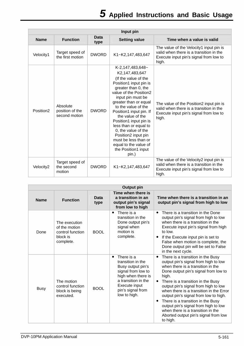
5 Applied Instructions and Basic Usage
DVP-10PM Application Manual 5-161
Input pin
Name Function Data type Setting value Time when a value is valid
Velocity1 Target speed of the first motion DWORD K1~K2,147,483,647
The value of the Velocity1 input pin is valid when there is a transition in the Execute input pin’s signal from low to high.
Position2 Absolute position of the second motion
DWORD
K-2,147,483,648~ K2,147,483,647
(If the value of the Position1 input pin is greater than 0, the
value of the Position2 input pin must be
greater than or equal to the value of the
Position1 input pin. If the value of the
Position1 input pin is less than or equal to 0, the value of the Position2 input pin
must be less than or equal to the value of the Position1 input
pin.)
The value of the Position2 input pin is valid when there is a transition in the Execute input pin’s signal from low to high.
Velocity2 Target speed of the second motion
DWORD K1~K2,147,483,647
The value of the Velocity2 input pin is valid when there is a transition in the Execute input pin’s signal from low to high.
Output pin
Name Function Data type
Time when there is a transition in an
output pin’s signal from low to high
Time when there is a transition in an output pin’s signal from high to low
Done
The execution of the motion control function block is complete.
BOOL
There is a transition in the Done output pin’s signal when motion is complete.
There is a transition in the Done output pin’s signal from high to low when there is a transition in the Execute input pin’s signal from high to low.
If the Execute input pin is set to False when motion is complete, the Done output pin will be set to False in the next cycle.
Busy
The motion control function block is being executed.
BOOL
There is a transition in the Busy output pin’s signal from low to high when there is a transition in the Execute input pin’s signal from low to high.
There is a transition in the Busy output pin’s signal from high to low when there is a transition in the Done output pin’s signal from low to high.
There is a transition in the Busy output pin’s signal from high to low when there is a transition in the Error output pin’s signal from low to high.
There is a transition in the Busy output pin’s signal from high to low when there is a transition in the Aborted output pin’s signal from low to high.
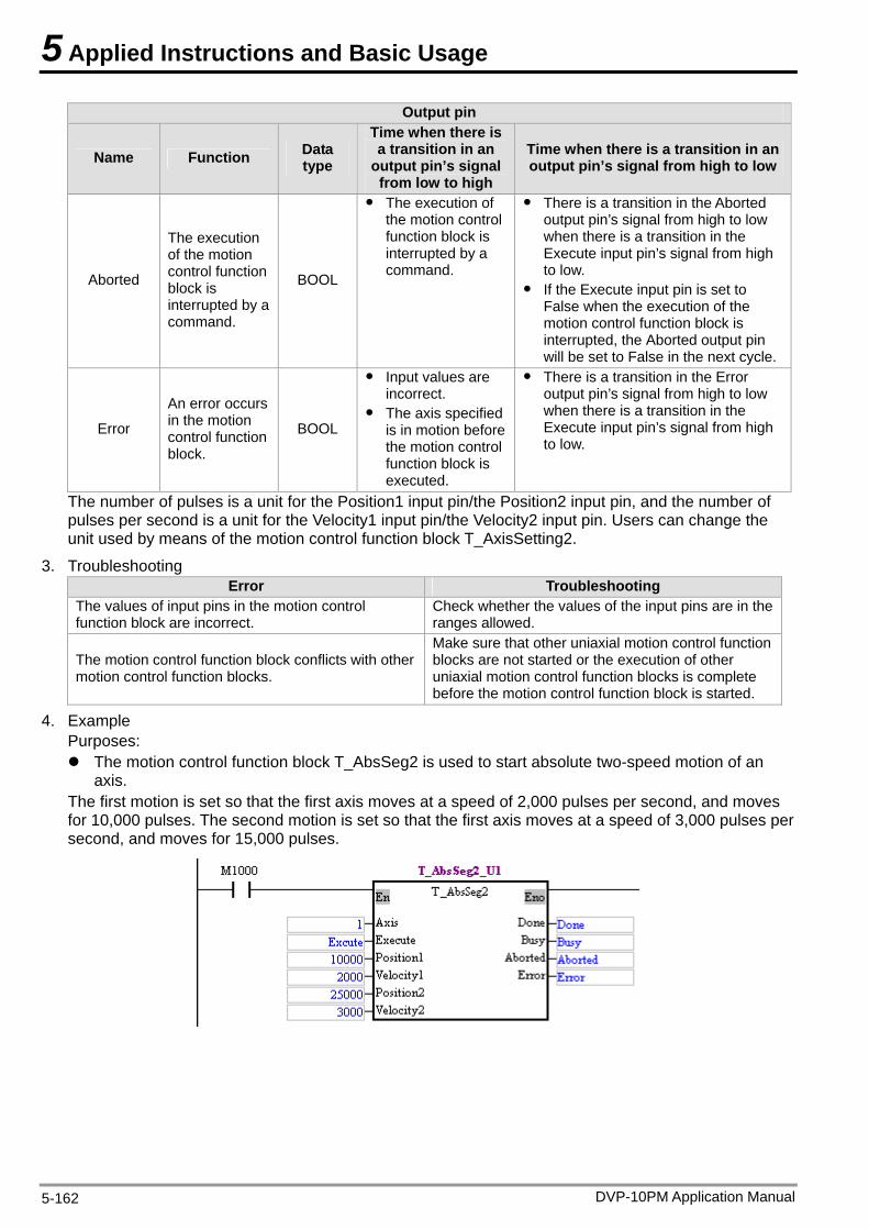
5 Applied Instructions and Basic Usage
DVP-10PM Application Manual 5-162
Output pin
Name Function Data type
Time when there is a transition in an
output pin’s signal from low to high
Time when there is a transition in an output pin’s signal from high to low
Aborted
The execution of the motion control function block is interrupted by a command.
BOOL
The execution of the motion control function block is interrupted by a command.
There is a transition in the Aborted output pin’s signal from high to low when there is a transition in the Execute input pin’s signal from high to low.
If the Execute input pin is set to False when the execution of the motion control function block is interrupted, the Aborted output pin will be set to False in the next cycle.
Error
An error occurs in the motion control function block.
BOOL
Input values are incorrect.
The axis specified is in motion before the motion control function block is executed.
There is a transition in the Error output pin’s signal from high to low when there is a transition in the Execute input pin’s signal from high to low.
The number of pulses is a unit for the Position1 input pin/the Position2 input pin, and the number of pulses per second is a unit for the Velocity1 input pin/the Velocity2 input pin. Users can change the unit used by means of the motion control function block T_AxisSetting2.
3. Troubleshooting Error Troubleshooting
The values of input pins in the motion control function block are incorrect.
Check whether the values of the input pins are in the ranges allowed.
The motion control function block conflicts with other motion control function blocks.
Make sure that other uniaxial motion control function blocks are not started or the execution of other uniaxial motion control function blocks is complete before the motion control function block is started.
4. Example Purposes: The motion control function block T_AbsSeg2 is used to start absolute two-speed motion of an
axis. The first motion is set so that the first axis moves at a speed of 2,000 pulses per second, and moves for 10,000 pulses. The second motion is set so that the first axis moves at a speed of 3,000 pulses per second, and moves for 15,000 pulses.
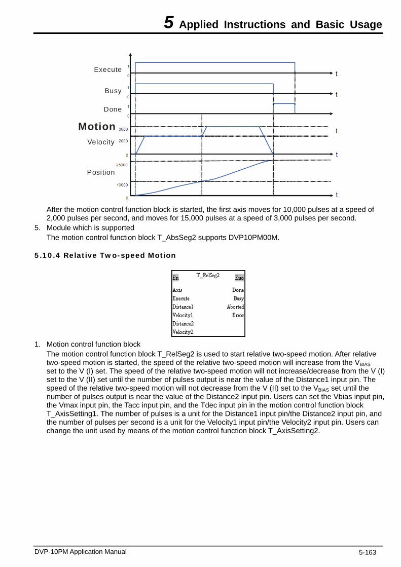
5 Applied Instructions and Basic Usage
Execute
Busy
Done
MotionVelocity
Position
After the motion control function block is started, the first axis moves for 10,000 pulses at a speed of 2,000 pulses per second, and moves for 15,000 pulses at a speed of 3,000 pulses per second.
5. Module which is supported The motion control function block T_AbsSeg2 supports DVP10PM00M.
5.10.4 Relative Two-speed Motion
1. Motion control function block
The motion control function block T_RelSeg2 is used to start relative two-speed motion. After relative two-speed motion is started, the speed of the relative two-speed motion will increase from the VBIAS set to the V (I) set. The speed of the relative two-speed motion will not increase/decrease from the V (I) set to the V (II) set until the number of pulses output is near the value of the Distance1 input pin. The speed of the relative two-speed motion will not decrease from the V (II) set to the VBIAS set until the number of pulses output is near the value of the Distance2 input pin. Users can set the Vbias input pin, the Vmax input pin, the Tacc input pin, and the Tdec input pin in the motion control function block T_AxisSetting1. The number of pulses is a unit for the Distance1 input pin/the Distance2 input pin, and the number of pulses per second is a unit for the Velocity1 input pin/the Velocity2 input pin. Users can change the unit used by means of the motion control function block T_AxisSetting2.
DVP-10PM Application Manual 5-163
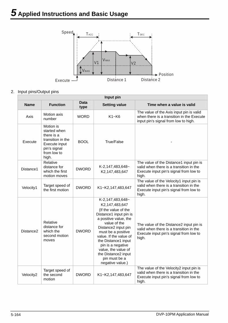
5 Applied Instructions and Basic Usage
Speed TACC TDEC
VMAX
PositionVBIAS
V1 V2
Execute Distance 2Distance 1
2. Input pins/Output pins Input pin
Name Function Data type Setting value Time when a value is valid
Axis Motion axis number WORD K1~K6
The value of the Axis input pin is valid when there is a transition in the Execute input pin’s signal from low to high.
Execute
Motion is started when there is a transition in the Execute input pin’s signal from low to high.
BOOL True/False -
Distance1
Relative distance for which the first motion moves
DWORD K-2,147,483,648~ K2,147,483,647
The value of the Distance1 input pin is valid when there is a transition in the Execute input pin’s signal from low to high.
Velocity1 Target speed of the first motion DWORD K1~K2,147,483,647
The value of the Velocity1 input pin is valid when there is a transition in the Execute input pin’s signal from low to high.
Distance2
Relative distance for which the second motion moves
DWORD
K-2,147,483,648~ K2,147,483,647
(If the value of the Distance1 input pin is a positive value, the
value of the Distance2 input pin must be a positive
value. If the value of the Distance1 input
pin is a negative value, the value of the Distance2 input
pin must be a negative value.)
The value of the Distance2 input pin is valid when there is a transition in the Execute input pin’s signal from low to high.
Velocity2 Target speed of the second motion
DWORD K1~K2,147,483,647
The value of the Velocity2 input pin is valid when there is a transition in the Execute input pin’s signal from low to high.
DVP-10PM Application Manual 5-164
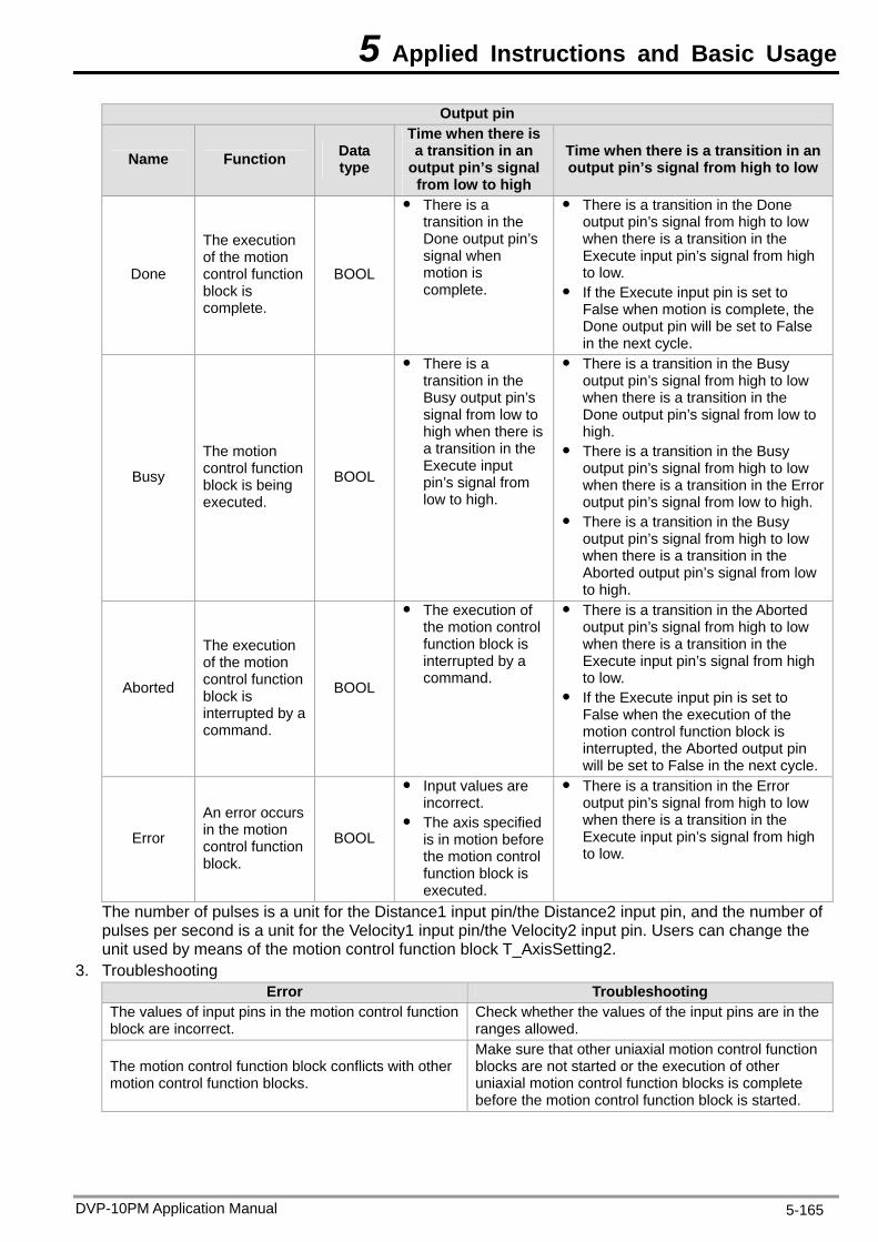
5 Applied Instructions and Basic Usage
Output pin
Name Function Data type
Time when there is a transition in an
output pin’s signal from low to high
Time when there is a transition in an output pin’s signal from high to low
Done
The execution of the motion control function block is complete.
BOOL
There is a transition in the Done output pin’s signal when motion is complete.
There is a transition in the Done output pin’s signal from high to low when there is a transition in the Execute input pin’s signal from high to low.
If the Execute input pin is set to False when motion is complete, the Done output pin will be set to False in the next cycle.
Busy
The motion control function block is being executed.
BOOL
There is a transition in the Busy output pin’s signal from low to high when there is a transition in the Execute input pin’s signal from low to high.
There is a transition in the Busy output pin’s signal from high to low when there is a transition in the Done output pin’s signal from low to high.
There is a transition in the Busy output pin’s signal from high to low when there is a transition in the Error output pin’s signal from low to high.
There is a transition in the Busy output pin’s signal from high to low when there is a transition in the Aborted output pin’s signal from low to high.
Aborted
The execution of the motion control function block is interrupted by a command.
BOOL
The execution of the motion control function block is interrupted by a command.
There is a transition in the Aborted output pin’s signal from high to low when there is a transition in the Execute input pin’s signal from high to low.
If the Execute input pin is set to False when the execution of the motion control function block is interrupted, the Aborted output pin will be set to False in the next cycle.
Error
An error occurs in the motion control function block.
BOOL
Input values are incorrect.
The axis specified is in motion before the motion control function block is executed.
There is a transition in the Error output pin’s signal from high to low when there is a transition in the Execute input pin’s signal from high to low.
The number of pulses is a unit for the Distance1 input pin/the Distance2 input pin, and the number of pulses per second is a unit for the Velocity1 input pin/the Velocity2 input pin. Users can change the unit used by means of the motion control function block T_AxisSetting2.
3. Troubleshooting Error Troubleshooting
The values of input pins in the motion control function block are incorrect.
Check whether the values of the input pins are in the ranges allowed.
The motion control function block conflicts with other motion control function blocks.
Make sure that other uniaxial motion control function blocks are not started or the execution of other uniaxial motion control function blocks is complete before the motion control function block is started.
DVP-10PM Application Manual 5-165
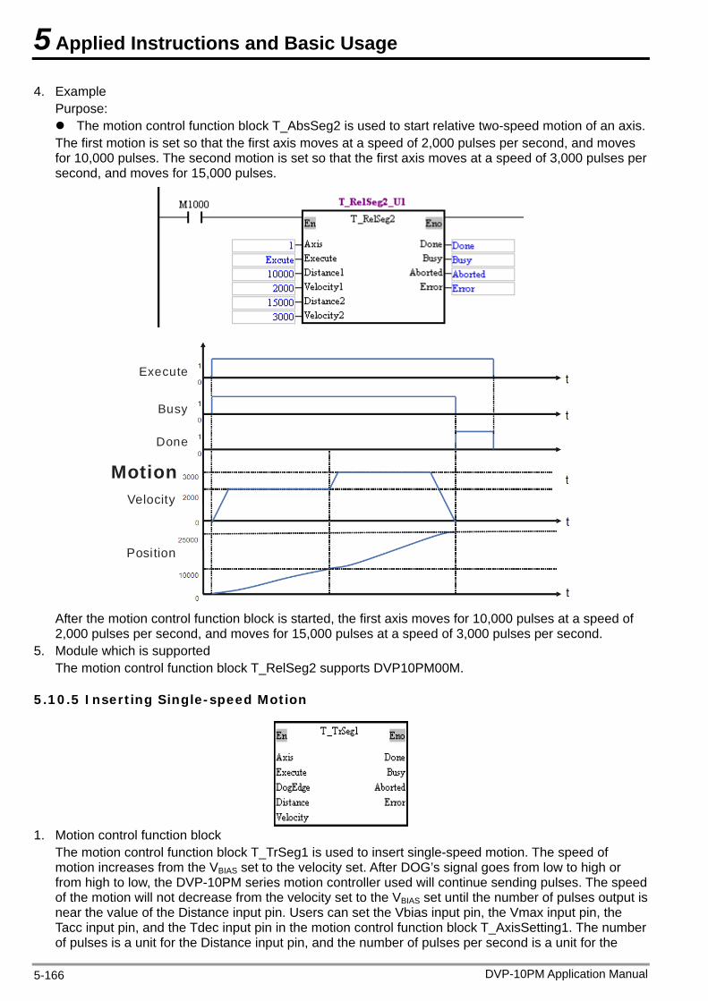
5 Applied Instructions and Basic Usage
4. Example Purpose: The motion control function block T_AbsSeg2 is used to start relative two-speed motion of an axis. The first motion is set so that the first axis moves at a speed of 2,000 pulses per second, and moves for 10,000 pulses. The second motion is set so that the first axis moves at a speed of 3,000 pulses per second, and moves for 15,000 pulses.
Execute
Busy
Done
MotionVelocity
Position
After the motion control function block is started, the first axis moves for 10,000 pulses at a speed of 2,000 pulses per second, and moves for 15,000 pulses at a speed of 3,000 pulses per second.
5. Module which is supported The motion control function block T_RelSeg2 supports DVP10PM00M.
5.10.5 Inserting Single-speed Motion
1. Motion control function block
The motion control function block T_TrSeg1 is used to insert single-speed motion. The speed of motion increases from the VBIAS set to the velocity set. After DOG’s signal goes from low to high or from high to low, the DVP-10PM series motion controller used will continue sending pulses. The speed of the motion will not decrease from the velocity set to the VBIAS set until the number of pulses output is near the value of the Distance input pin. Users can set the Vbias input pin, the Vmax input pin, the Tacc input pin, and the Tdec input pin in the motion control function block T_AxisSetting1. The number of pulses is a unit for the Distance input pin, and the number of pulses per second is a unit for the
DVP-10PM Application Manual 5-166
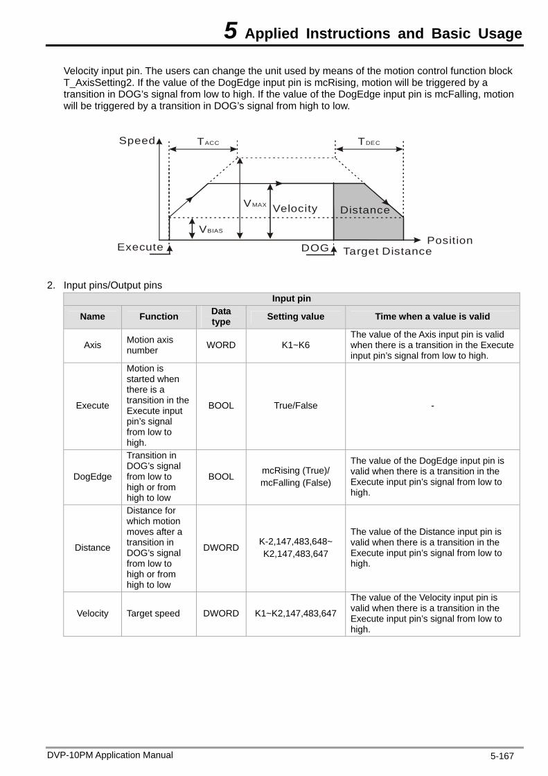
5 Applied Instructions and Basic Usage
Velocity input pin. The users can change the unit used by means of the motion control function block T_AxisSetting2. If the value of the DogEdge input pin is mcRising, motion will be triggered by a transition in DOG’s signal from low to high. If the value of the DogEdge input pin is mcFalling, motion will be triggered by a transition in DOG’s signal from high to low.
Speed TACC TDEC
VMAX
PositionVBIAS
Execute
Velocity Distance
DOG Target Distance
2. Input pins/Output pins
Input pin
Name Function Data type Setting value Time when a value is valid
Axis Motion axis number WORD K1~K6
The value of the Axis input pin is valid when there is a transition in the Execute input pin’s signal from low to high.
Execute
Motion is started when there is a transition in the Execute input pin’s signal from low to high.
BOOL True/False -
DogEdge
Transition in DOG’s signal from low to high or from high to low
BOOL mcRising (True)/ mcFalling (False)
The value of the DogEdge input pin is valid when there is a transition in the Execute input pin’s signal from low to high.
Distance
Distance for which motion moves after a transition in DOG’s signal from low to high or from high to low
DWORD K-2,147,483,648~ K2,147,483,647
The value of the Distance input pin is valid when there is a transition in the Execute input pin’s signal from low to high.
Velocity Target speed DWORD K1~K2,147,483,647
The value of the Velocity input pin is valid when there is a transition in the Execute input pin’s signal from low to high.
DVP-10PM Application Manual 5-167
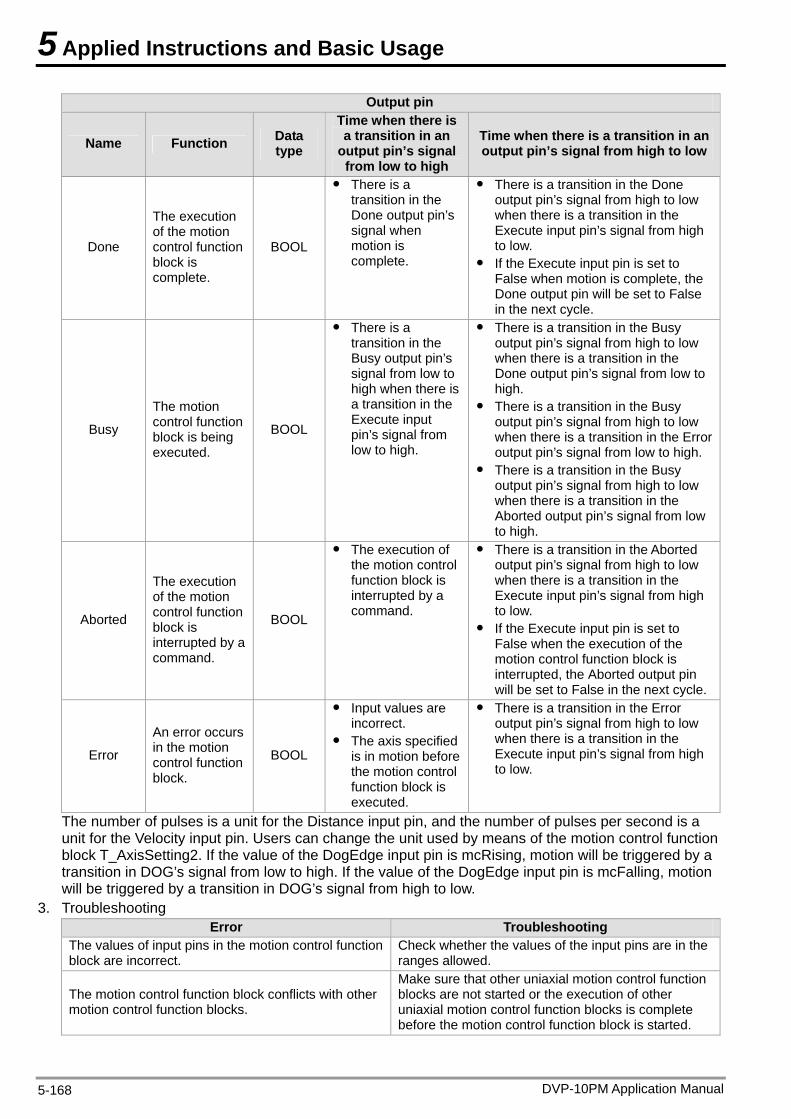
5 Applied Instructions and Basic Usage
Output pin
Name Function Data type
Time when there is a transition in an
output pin’s signal from low to high
Time when there is a transition in an output pin’s signal from high to low
Done
The execution of the motion control function block is complete.
BOOL
There is a transition in the Done output pin’s signal when motion is complete.
There is a transition in the Done output pin’s signal from high to low when there is a transition in the Execute input pin’s signal from high to low.
If the Execute input pin is set to False when motion is complete, the Done output pin will be set to False in the next cycle.
Busy
The motion control function block is being executed.
BOOL
There is a transition in the Busy output pin’s signal from low to high when there is a transition in the Execute input pin’s signal from low to high.
There is a transition in the Busy output pin’s signal from high to low when there is a transition in the Done output pin’s signal from low to high.
There is a transition in the Busy output pin’s signal from high to low when there is a transition in the Error output pin’s signal from low to high.
There is a transition in the Busy output pin’s signal from high to low when there is a transition in the Aborted output pin’s signal from low to high.
Aborted
The execution of the motion control function block is interrupted by a command.
BOOL
The execution of the motion control function block is interrupted by a command.
There is a transition in the Aborted output pin’s signal from high to low when there is a transition in the Execute input pin’s signal from high to low.
If the Execute input pin is set to False when the execution of the motion control function block is interrupted, the Aborted output pin will be set to False in the next cycle.
Error
An error occurs in the motion control function block.
BOOL
Input values are incorrect.
The axis specified is in motion before the motion control function block is executed.
There is a transition in the Error output pin’s signal from high to low when there is a transition in the Execute input pin’s signal from high to low.
The number of pulses is a unit for the Distance input pin, and the number of pulses per second is a unit for the Velocity input pin. Users can change the unit used by means of the motion control function block T_AxisSetting2. If the value of the DogEdge input pin is mcRising, motion will be triggered by a transition in DOG’s signal from low to high. If the value of the DogEdge input pin is mcFalling, motion will be triggered by a transition in DOG’s signal from high to low.
3. Troubleshooting Error Troubleshooting
The values of input pins in the motion control function block are incorrect.
Check whether the values of the input pins are in the ranges allowed.
The motion control function block conflicts with other motion control function blocks.
Make sure that other uniaxial motion control function blocks are not started or the execution of other uniaxial motion control function blocks is complete before the motion control function block is started.
DVP-10PM Application Manual 5-168
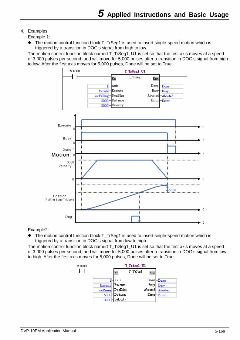
5 Applied Instructions and Basic Usage
4. Examples Example 1: The motion control function block T_TrSeg1 is used to insert single-speed motion which is
triggered by a transition in DOG’s signal from high to low. The motion control function block named T_TrSeg1_U1 is set so that the first axis moves at a speed of 3,000 pulses per second, and will move for 5,000 pulses after a transition in DOG’s signal from high to low. After the first axis moves for 5,000 pulses, Done will be set to True.
Execute
Busy
Done
Motion
Velocity
Position(Falling Edge Tr igger)
Dog
Example2: The motion control function block T_TrSeg1 is used to insert single-speed motion which is
triggered by a transition in DOG’s signal from low to high. The motion control function block named T_TrSeg1_U1 is set so that the first axis moves at a speed of 3,000 pulses per second, and will move for 5,000 pulses after a transition in DOG’s signal from low to high. After the first axis moves for 5,000 pulses, Done will be set to True.
DVP-10PM Application Manual 5-169
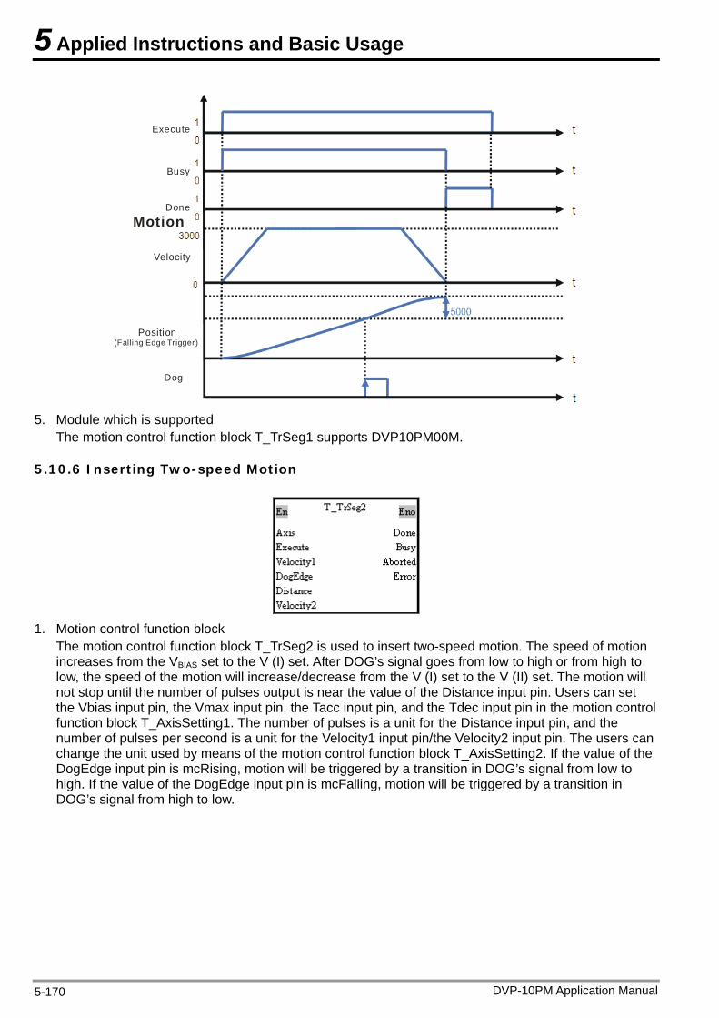
5 Applied Instructions and Basic Usage
Execute
Busy
Done
Motion
Velocity
Position(Falling Edge Trigger)
Dog
5. Module which is supported
The motion control function block T_TrSeg1 supports DVP10PM00M.
5.10.6 Inserting Two-speed Motion
1. Motion control function block
The motion control function block T_TrSeg2 is used to insert two-speed motion. The speed of motion increases from the VBIAS set to the V (I) set. After DOG’s signal goes from low to high or from high to low, the speed of the motion will increase/decrease from the V (I) set to the V (II) set. The motion will not stop until the number of pulses output is near the value of the Distance input pin. Users can set the Vbias input pin, the Vmax input pin, the Tacc input pin, and the Tdec input pin in the motion control function block T_AxisSetting1. The number of pulses is a unit for the Distance input pin, and the number of pulses per second is a unit for the Velocity1 input pin/the Velocity2 input pin. The users can change the unit used by means of the motion control function block T_AxisSetting2. If the value of the DogEdge input pin is mcRising, motion will be triggered by a transition in DOG’s signal from low to high. If the value of the DogEdge input pin is mcFalling, motion will be triggered by a transition in DOG’s signal from high to low.
DVP-10PM Application Manual 5-170
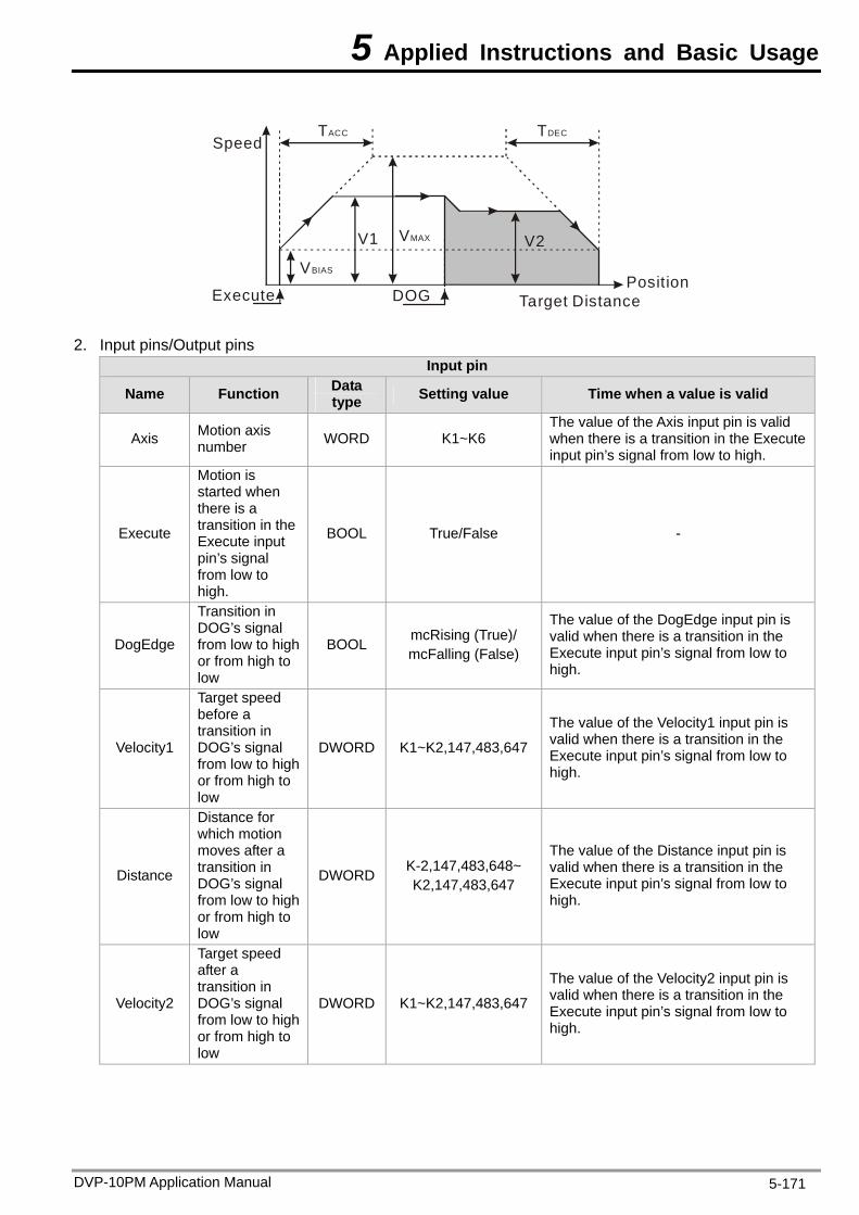
5 Applied Instructions and Basic Usage
SpeedTACC TDEC
VMAX
PositionVBIAS
Execute
V1 V2
Target DistanceDOG
2. Input pins/Output pins Input pin
Name Function Data type Setting value Time when a value is valid
Axis Motion axis number WORD K1~K6
The value of the Axis input pin is valid when there is a transition in the Execute input pin’s signal from low to high.
Execute
Motion is started when there is a transition in the Execute input pin’s signal from low to high.
BOOL True/False -
DogEdge
Transition in DOG’s signal from low to high or from high to low
BOOL mcRising (True)/ mcFalling (False)
The value of the DogEdge input pin is valid when there is a transition in the Execute input pin’s signal from low to high.
Velocity1
Target speed before a transition in DOG’s signal from low to high or from high to low
DWORD K1~K2,147,483,647
The value of the Velocity1 input pin is valid when there is a transition in the Execute input pin’s signal from low to high.
Distance
Distance for which motion moves after a transition in DOG’s signal from low to high or from high to low
DWORD K-2,147,483,648~ K2,147,483,647
The value of the Distance input pin is valid when there is a transition in the Execute input pin’s signal from low to high.
Velocity2
Target speed after a transition in DOG’s signal from low to high or from high to low
DWORD K1~K2,147,483,647
The value of the Velocity2 input pin is valid when there is a transition in the Execute input pin’s signal from low to high.
DVP-10PM Application Manual 5-171
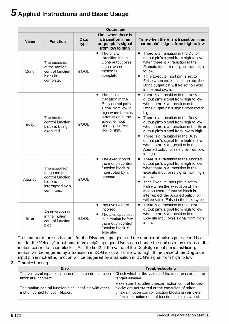
5 Applied Instructions and Basic Usage
Output pin
Name Function Data type
Time when there is a transition in an
output pin’s signal from low to high
Time when there is a transition in an output pin’s signal from high to low
Done
The execution of the motion control function block is complete.
BOOL
There is a transition in the Done output pin’s signal when motion is complete.
There is a transition in the Done output pin’s signal from high to low when there is a transition in the Execute input pin’s signal from high to low.
If the Execute input pin is set to False when motion is complete, the Done output pin will be set to False in the next cycle.
Busy
The motion control function block is being executed.
BOOL
There is a transition in the Busy output pin’s signal from low to high when there is a transition in the Execute input pin’s signal from low to high.
There is a transition in the Busy output pin’s signal from high to low when there is a transition in the Done output pin’s signal from low to high.
There is a transition in the Busy output pin’s signal from high to low when there is a transition in the Error output pin’s signal from low to high.
There is a transition in the Busy output pin’s signal from high to low when there is a transition in the Aborted output pin’s signal from low to high.
Aborted
The execution of the motion control function block is interrupted by a command.
BOOL
The execution of the motion control function block is interrupted by a command.
There is a transition in the Aborted output pin’s signal from high to low when there is a transition in the Execute input pin’s signal from high to low.
If the Execute input pin is set to False when the execution of the motion control function block is interrupted, the Aborted output pin will be set to False in the next cycle.
Error
An error occurs in the motion control function block.
BOOL
Input values are incorrect.
The axis specified is in motion before the motion control function block is executed.
There is a transition in the Error output pin’s signal from high to low when there is a transition in the Execute input pin’s signal from high to low.
The number of pulses is a unit for the Distance input pin, and the number of pulses per second is a unit for the Velocity1 input pin/the Velocity2 input pin. Users can change the unit used by means of the motion control function block T_AxisSetting2. If the value of the DogEdge input pin is mcRising, motion will be triggered by a transition in DOG’s signal from low to high. If the value of the DogEdge input pin is mcFalling, motion will be triggered by a transition in DOG’s signal from high to low.
3. Troubleshooting Error Troubleshooting
The values of input pins in the motion control function block are incorrect.
Check whether the values of the input pins are in the ranges allowed.
The motion control function block conflicts with other motion control function blocks.
Make sure that other uniaxial motion control function blocks are not started or the execution of other uniaxial motion control function blocks is complete before the motion control function block is started.
DVP-10PM Application Manual 5-172

5 Applied Instructions and Basic Usage
4. Example The motion control function block T_TrSeg2 is used to insert two-speed motion which is triggered by a transition in DOG’s signal from low to high. The motion control function block named T_TrSeg2_U1 is set so that the first axis moves at a speed of 3,000 pulses per second, and will move for 2,000 pulses at a speed of 1,000 pulses per second after a transition in DOG’s signal from low to high.
Busy
Done
Executet0
0
0
1
1
1
0
3000
Velocity
Position(Rising Edge Trigger)
t
t
tMotion
t
Dogt
2000
1000
After the first axis moves for 2,000 pulses, Done will be set to True.
5. Module which is supported The motion control function block T_TrSeg2 supports DVP10PM00M.
5.10.7 JOG Motion
1. Motion control function block
The motion control function block T_Jog is used to start JOG motion. The value of the Axis input pin indicates an axis number, and the value of the Velocity input pin indicates the speed of JOG motion. If the PositiveEnable input pin is set to True, positive JOG motion will be started. If the NegativeEnable input pin is set to True, negative JOG motion will be started. The number of pulses per second is a unit for the Velocity input pin. Users can change the unit used by means of the motion control function block T_AxisSetting2.
DVP-10PM Application Manual 5-173
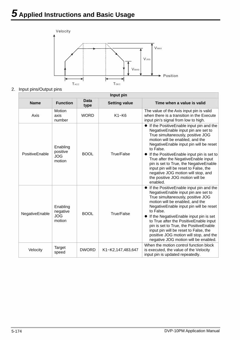
5 Applied Instructions and Basic Usage
VBIAS
VJOG
VMAX
Velocity
TACC TDEC
Position
2. Input pins/Output pins
Input pin
Name Function Data type Setting value Time when a value is valid
Axis Motion axis number
WORD K1~K6 The value of the Axis input pin is valid when there is a transition in the Execute input pin’s signal from low to high.
PositiveEnable
Enabling positive JOG motion
BOOL True/False
If the PositiveEnable input pin and the NegativeEnable input pin are set to True simultaneously, positive JOG motion will be enabled, and the NegativeEnable input pin will be reset to False.
If the PositiveEnable input pin is set to True after the NegativeEnable input pin is set to True, the NegativeEnable input pin will be reset to False, the negative JOG motion will stop, and the positive JOG motion will be enabled.
NegativeEnable
Enabling negative JOG motion
BOOL True/False
If the PositiveEnable input pin and the NegativeEnable input pin are set to True simultaneously, positive JOG motion will be enabled, and the NegativeEnable input pin will be reset to False.
If the NegativeEnable input pin is set to True after the PositiveEnable input pin is set to True, the PositiveEnable input pin will be reset to False, the positive JOG motion will stop, and the negative JOG motion will be enabled.
Velocity Target speed DWORD K1~K2,147,483,647
When the motion control function block is executed, the value of the Velocity input pin is updated repeatedly.
DVP-10PM Application Manual 5-174
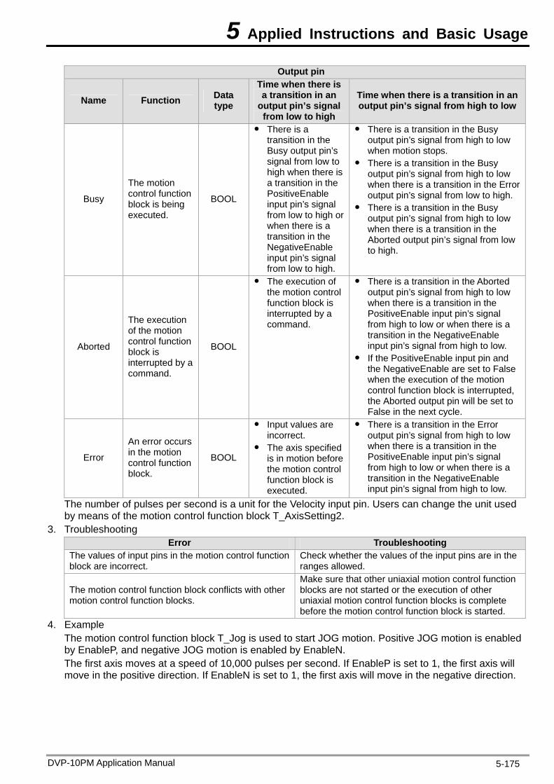
5 Applied Instructions and Basic Usage
Output pin
Name Function Data type
Time when there is a transition in an
output pin’s signal from low to high
Time when there is a transition in an output pin’s signal from high to low
Busy
The motion control function block is being executed.
BOOL
There is a transition in the Busy output pin’s signal from low to high when there is a transition in the PositiveEnable input pin’s signal from low to high or when there is a transition in the NegativeEnable input pin’s signal from low to high.
There is a transition in the Busy output pin’s signal from high to low when motion stops.
There is a transition in the Busy output pin’s signal from high to low when there is a transition in the Error output pin’s signal from low to high.
There is a transition in the Busy output pin’s signal from high to low when there is a transition in the Aborted output pin’s signal from low to high.
Aborted
The execution of the motion control function block is interrupted by a command.
BOOL
The execution of the motion control function block is interrupted by a command.
There is a transition in the Aborted output pin’s signal from high to low when there is a transition in the PositiveEnable input pin’s signal from high to low or when there is a transition in the NegativeEnable input pin’s signal from high to low.
If the PositiveEnable input pin and the NegativeEnable are set to False when the execution of the motion control function block is interrupted, the Aborted output pin will be set to False in the next cycle.
Error
An error occurs in the motion control function block.
BOOL
Input values are incorrect.
The axis specified is in motion before the motion control function block is executed.
There is a transition in the Error output pin’s signal from high to low when there is a transition in the PositiveEnable input pin’s signal from high to low or when there is a transition in the NegativeEnable input pin’s signal from high to low.
The number of pulses per second is a unit for the Velocity input pin. Users can change the unit used by means of the motion control function block T_AxisSetting2.
3. Troubleshooting Error Troubleshooting
The values of input pins in the motion control function block are incorrect.
Check whether the values of the input pins are in the ranges allowed.
The motion control function block conflicts with other motion control function blocks.
Make sure that other uniaxial motion control function blocks are not started or the execution of other uniaxial motion control function blocks is complete before the motion control function block is started.
4. Example The motion control function block T_Jog is used to start JOG motion. Positive JOG motion is enabled by EnableP, and negative JOG motion is enabled by EnableN. The first axis moves at a speed of 10,000 pulses per second. If EnableP is set to 1, the first axis will move in the positive direction. If EnableN is set to 1, the first axis will move in the negative direction.
DVP-10PM Application Manual 5-175
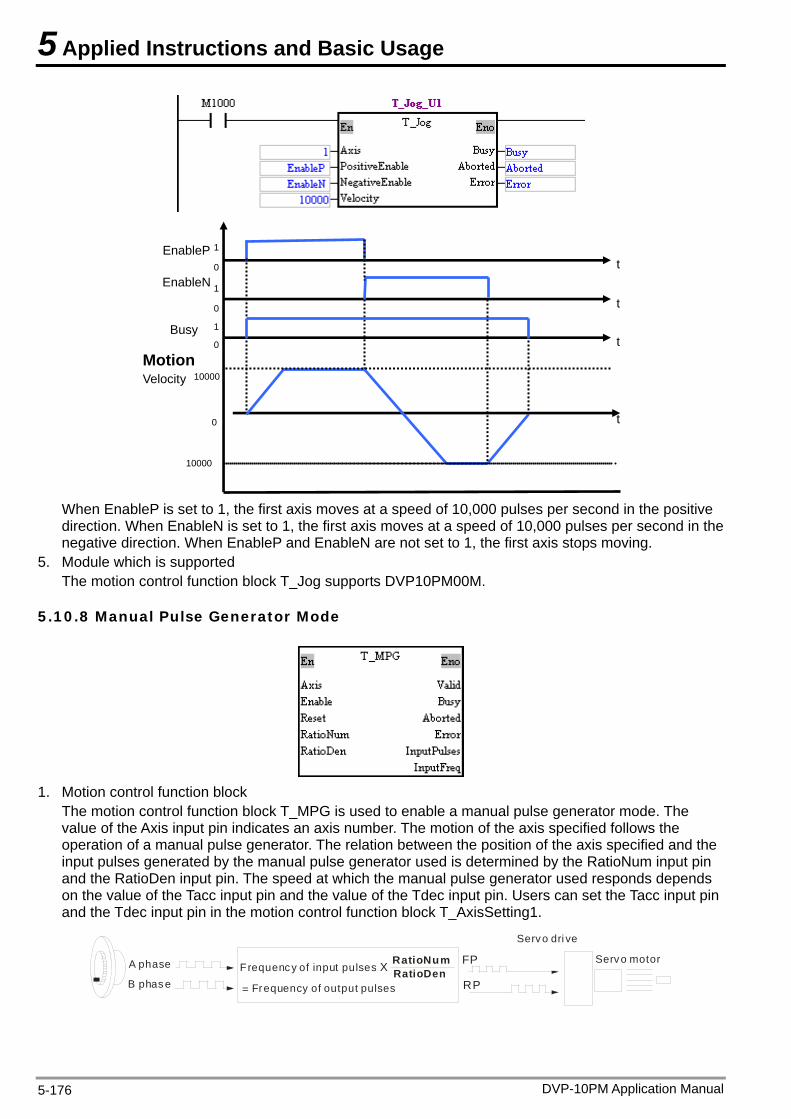
5 Applied Instructions and Basic Usage
EnableP
Busy
t
t
t
t
0
0
0
1
1
EnableN
Velocity
0
1
Motion
10000
10000
When EnableP is set to 1, the first axis moves at a speed of 10,000 pulses per second in the positive direction. When EnableN is set to 1, the first axis moves at a speed of 10,000 pulses per second in the negative direction. When EnableP and EnableN are not set to 1, the first axis stops moving.
5. Module which is supported The motion control function block T_Jog supports DVP10PM00M.
5.10.8 Manual Pulse Generator Mode
1. Motion control function block
The motion control function block T_MPG is used to enable a manual pulse generator mode. The value of the Axis input pin indicates an axis number. The motion of the axis specified follows the operation of a manual pulse generator. The relation between the position of the axis specified and the input pulses generated by the manual pulse generator used is determined by the RatioNum input pin and the RatioDen input pin. The speed at which the manual pulse generator used responds depends on the value of the Tacc input pin and the value of the Tdec input pin. Users can set the Tacc input pin and the Tdec input pin in the motion control function block T_AxisSetting1.
A phase
B phas e
FP
RP
Servo dri ve
Servo motorFrequency of input pulses X
= Frequency of output pulses
RatioNumRatioDen
DVP-10PM Application Manual 5-176
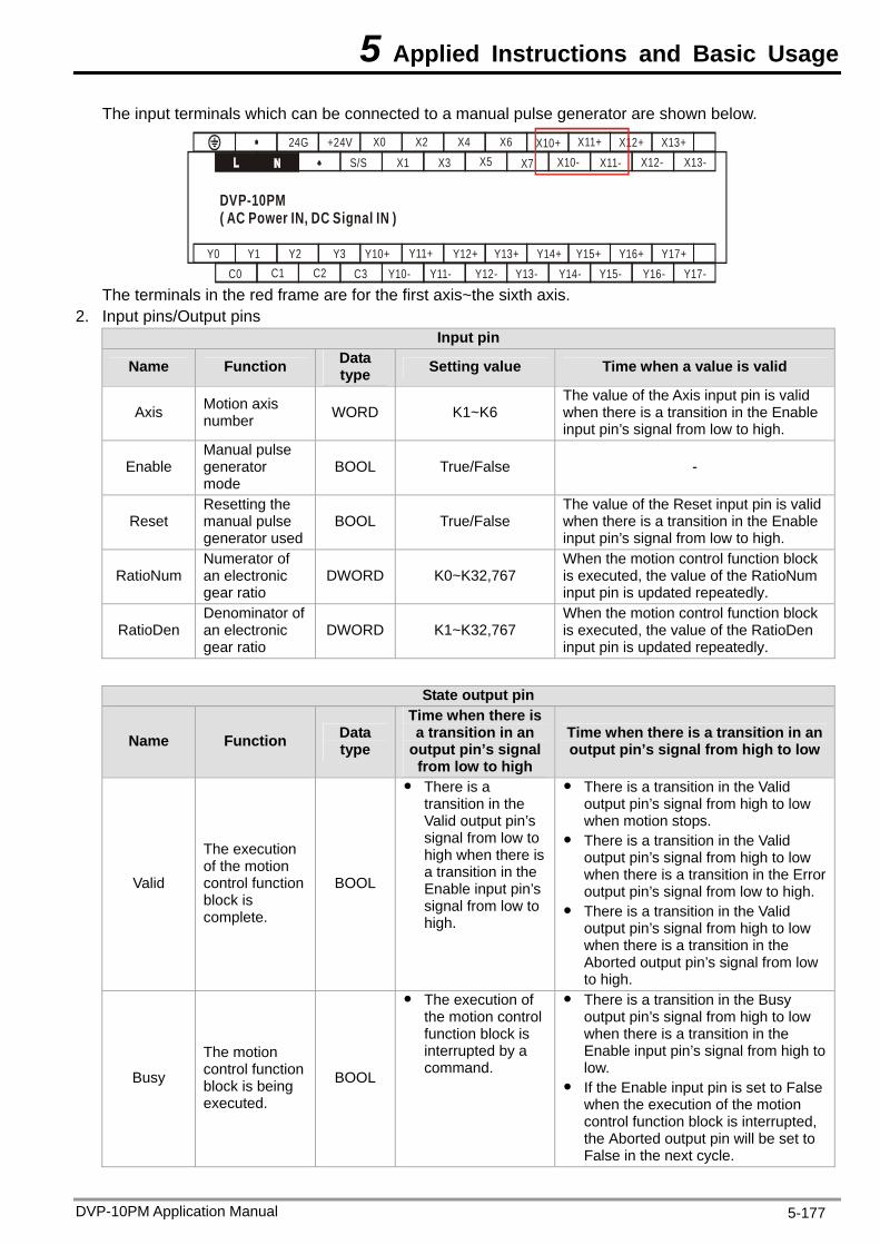
5 Applied Instructions and Basic Usage
The input terminals which can be connected to a manual pulse generator are shown below.
S/S24G
X1 X3 X5 X7 X10- X11- X12- X13-+24V X0 X2 X4 X6 X10+ X11+ X12+ X13+
C3 Y10- Y11- Y12- Y13- Y14- Y15- Y16- Y17-Y10+ Y11+ Y12+ Y13+ Y14+ Y15+ Y16+ Y17+Y0 Y1 Y2 Y3
C2C1C0
DVP-10PM( AC Power IN, DC Signal IN )
The terminals in the red frame are for the first axis~the sixth axis.
2. Input pins/Output pins Input pin
Name Function Data type Setting value Time when a value is valid
Axis Motion axis number WORD K1~K6
The value of the Axis input pin is valid when there is a transition in the Enable input pin’s signal from low to high.
Enable Manual pulse generator mode
BOOL True/False -
Reset Resetting the manual pulse generator used
BOOL True/False The value of the Reset input pin is valid when there is a transition in the Enable input pin’s signal from low to high.
RatioNum Numerator of an electronic gear ratio
DWORD K0~K32,767 When the motion control function block is executed, the value of the RatioNum input pin is updated repeatedly.
RatioDen Denominator of an electronic gear ratio
DWORD K1~K32,767 When the motion control function block is executed, the value of the RatioDen input pin is updated repeatedly.
State output pin
Name Function Data type
Time when there is a transition in an
output pin’s signal from low to high
Time when there is a transition in an output pin’s signal from high to low
Valid
The execution of the motion control function block is complete.
BOOL
There is a transition in the Valid output pin’s signal from low to high when there is a transition in the Enable input pin’s signal from low to high.
There is a transition in the Valid output pin’s signal from high to low when motion stops.
There is a transition in the Valid output pin’s signal from high to low when there is a transition in the Error output pin’s signal from low to high.
There is a transition in the Valid output pin’s signal from high to low when there is a transition in the Aborted output pin’s signal from low to high.
Busy
The motion control function block is being executed.
BOOL
The execution of the motion control function block is interrupted by a command.
There is a transition in the Busy output pin’s signal from high to low when there is a transition in the Enable input pin’s signal from high to low.
If the Enable input pin is set to False when the execution of the motion control function block is interrupted, the Aborted output pin will be set to False in the next cycle.
DVP-10PM Application Manual 5-177
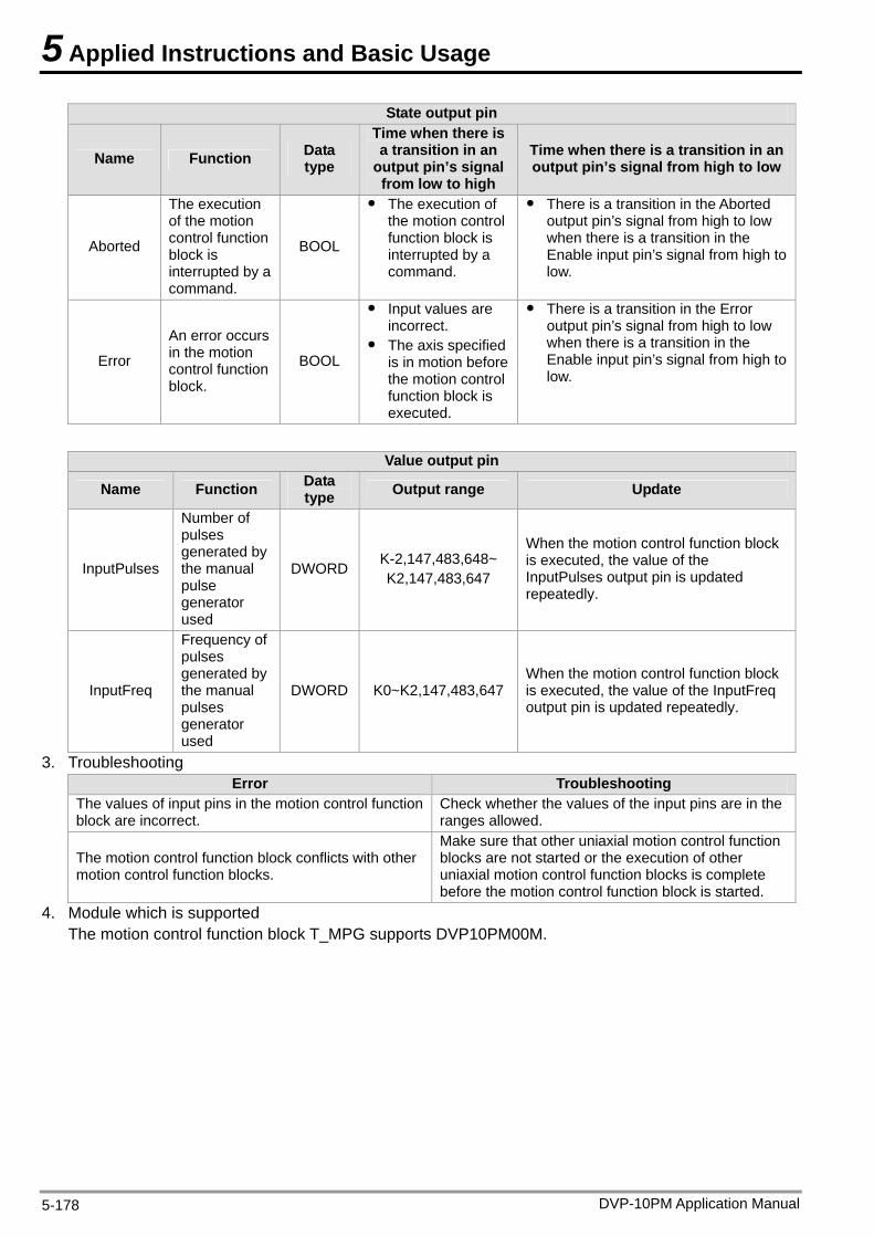
5 Applied Instructions and Basic Usage
DVP-10PM Application Manual 5-178
State output pin
Name Function Data type
Time when there is a transition in an
output pin’s signal from low to high
Time when there is a transition in an output pin’s signal from high to low
Aborted
The execution of the motion control function block is interrupted by a command.
BOOL
The execution of the motion control function block is interrupted by a command.
There is a transition in the Aborted output pin’s signal from high to low when there is a transition in the Enable input pin’s signal from high to low.
Error
An error occurs in the motion control function block.
BOOL
Input values are incorrect.
The axis specified is in motion before the motion control function block is executed.
There is a transition in the Error output pin’s signal from high to low when there is a transition in the Enable input pin’s signal from high to low.
Value output pin
Name Function Data type Output range Update
InputPulses
Number of pulses generated by the manual pulse generator used
DWORD K-2,147,483,648~ K2,147,483,647
When the motion control function block is executed, the value of the InputPulses output pin is updated repeatedly.
InputFreq
Frequency of pulses generated by the manual pulses generator used
DWORD K0~K2,147,483,647 When the motion control function block is executed, the value of the InputFreq output pin is updated repeatedly.
3. Troubleshooting Error Troubleshooting
The values of input pins in the motion control function block are incorrect.
Check whether the values of the input pins are in the ranges allowed.
The motion control function block conflicts with other motion control function blocks.
Make sure that other uniaxial motion control function blocks are not started or the execution of other uniaxial motion control function blocks is complete before the motion control function block is started.
4. Module which is supported The motion control function block T_MPG supports DVP10PM00M.
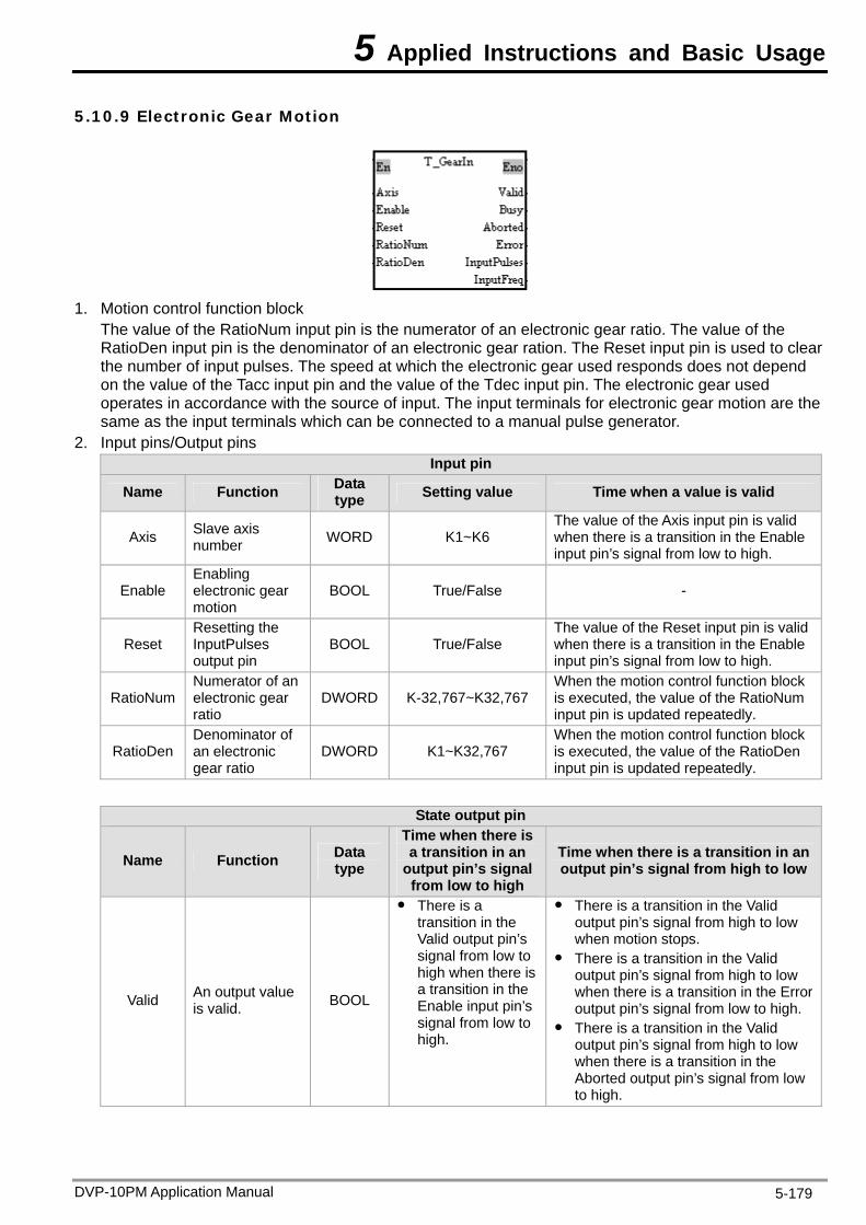
5 Applied Instructions and Basic Usage
5.10.9 Electronic Gear Motion
1. Motion control function block
The value of the RatioNum input pin is the numerator of an electronic gear ratio. The value of the RatioDen input pin is the denominator of an electronic gear ration. The Reset input pin is used to clear the number of input pulses. The speed at which the electronic gear used responds does not depend on the value of the Tacc input pin and the value of the Tdec input pin. The electronic gear used operates in accordance with the source of input. The input terminals for electronic gear motion are the same as the input terminals which can be connected to a manual pulse generator.
2. Input pins/Output pins Input pin
Name Function Data type Setting value Time when a value is valid
Axis Slave axis number WORD K1~K6
The value of the Axis input pin is valid when there is a transition in the Enable input pin’s signal from low to high.
Enable Enabling electronic gear motion
BOOL True/False -
Reset Resetting the InputPulses output pin
BOOL True/False The value of the Reset input pin is valid when there is a transition in the Enable input pin’s signal from low to high.
RatioNum Numerator of an electronic gear ratio
DWORD K-32,767~K32,767 When the motion control function block is executed, the value of the RatioNum input pin is updated repeatedly.
RatioDen Denominator of an electronic gear ratio
DWORD K1~K32,767 When the motion control function block is executed, the value of the RatioDen input pin is updated repeatedly.
State output pin
Name Function Data type
Time when there is a transition in an
output pin’s signal from low to high
Time when there is a transition in an output pin’s signal from high to low
Valid An output value is valid. BOOL
There is a transition in the Valid output pin’s signal from low to high when there is a transition in the Enable input pin’s signal from low to high.
There is a transition in the Valid output pin’s signal from high to low when motion stops.
There is a transition in the Valid output pin’s signal from high to low when there is a transition in the Error output pin’s signal from low to high.
There is a transition in the Valid output pin’s signal from high to low when there is a transition in the Aborted output pin’s signal from low to high.
DVP-10PM Application Manual 5-179
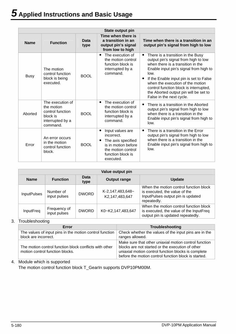
5 Applied Instructions and Basic Usage
DVP-10PM Application Manual 5-180
State output pin
Name Function Data type
Time when there is a transition in an
output pin’s signal from low to high
Time when there is a transition in an output pin’s signal from high to low
Busy
The motion control function block is being executed.
BOOL
The execution of the motion control function block is interrupted by a command.
There is a transition in the Busy output pin’s signal from high to low when there is a transition in the Enable input pin’s signal from high to low.
If the Enable input pin is set to False when the execution of the motion control function block is interrupted, the Aborted output pin will be set to False in the next cycle.
Aborted
The execution of the motion control function block is interrupted by a command.
BOOL
The execution of the motion control function block is interrupted by a command.
There is a transition in the Aborted output pin’s signal from high to low when there is a transition in the Enable input pin’s signal from high to low.
Error
An error occurs in the motion control function block.
BOOL
Input values are incorrect.
The axis specified is in motion before the motion control function block is executed.
There is a transition in the Error output pin’s signal from high to low when there is a transition in the Enable input pin’s signal from high to low.
Value output pin
Name Function Data type Output range Update
InputPulses Number of input pulses DWORD K-2,147,483,648~
K2,147,483,647
When the motion control function block is executed, the value of the InputPulses output pin is updated repeatedly.
InputFreq Frequency of input pulses DWORD K0~K2,147,483,647
When the motion control function block is executed, the value of the InputFreq output pin is updated repeatedly.
3. Troubleshooting Error Troubleshooting
The values of input pins in the motion control function block are incorrect.
Check whether the values of the input pins are in the ranges allowed.
The motion control function block conflicts with other motion control function blocks.
Make sure that other uniaxial motion control function blocks are not started or the execution of other uniaxial motion control function blocks is complete before the motion control function block is started.
4. Module which is supported The motion control function block T_GearIn supports DVP10PM00M.
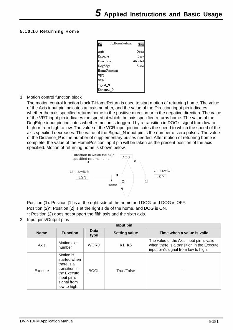
5 Applied Instructions and Basic Usage
5.10.10 Returning Home
1. Motion control function block
The motion control function block T-HomeReturn is used to start motion of returning home. The value of the Axis input pin indicates an axis number, and the value of the Direction input pin indicates whether the axis specified returns home in the positive direction or in the negative direction. The value of the VRT input pin indicates the speed at which the axis specified returns home. The value of the DogEdge input pin indicates whether motion is triggered by a transition in DOG’s signal from low to high or from high to low. The value of the VCR input pin indicates the speed to which the speed of the axis specified decreases. The value of the Signal_N input pin is the number of zero pulses. The value of the Distance_P is the number of supplementary pulses needed. After motion of returning home is complete, the value of the HomePosition input pin will be taken as the present position of the axis specified. Motion of returning home is shown below.
Limit switch
Direction in which the axis specif ied returns home
Home
Limit switch
LSN
DOG
LSP[2] [1 ]
Position (1): Position [1] is at the right side of the home and DOG, and DOG is OFF. Position (2)*: Position [2] is at the right side of the home, and DOG is ON. *: Position (2) does not support the fifth axis and the sixth axis.
2. Input pins/Output pins Input pin
Name Function Data type Setting value Time when a value is valid
Axis Motion axis number WORD K1~K6
The value of the Axis input pin is valid when there is a transition in the Execute input pin’s signal from low to high.
Execute
Motion is started when there is a transition in the Execute input pin’s signal from low to high.
BOOL True/False -
DVP-10PM Application Manual 5-181
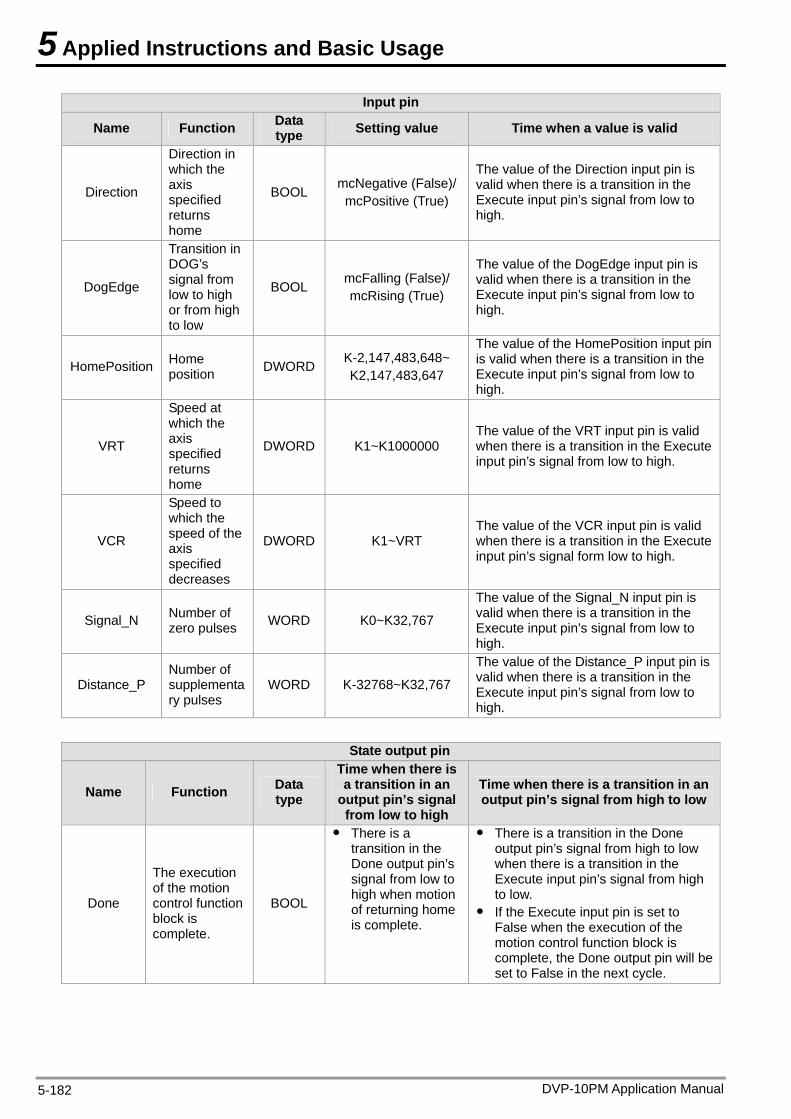
5 Applied Instructions and Basic Usage
DVP-10PM Application Manual 5-182
Input pin
Name Function Data type Setting value Time when a value is valid
Direction
Direction in which the axis specified returns home
BOOL mcNegative (False)/ mcPositive (True)
The value of the Direction input pin is valid when there is a transition in the Execute input pin’s signal from low to high.
DogEdge
Transition in DOG’s signal from low to high or from high to low
BOOL mcFalling (False)/ mcRising (True)
The value of the DogEdge input pin is valid when there is a transition in the Execute input pin’s signal from low to high.
HomePosition Home position DWORD K-2,147,483,648~
K2,147,483,647
The value of the HomePosition input pin is valid when there is a transition in the Execute input pin’s signal from low to high.
VRT
Speed at which the axis specified returns home
DWORD K1~K1000000 The value of the VRT input pin is valid when there is a transition in the Execute input pin’s signal from low to high.
VCR
Speed to which the speed of the axis specified decreases
DWORD K1~VRT The value of the VCR input pin is valid when there is a transition in the Execute input pin’s signal form low to high.
Signal_N Number of zero pulses WORD K0~K32,767
The value of the Signal_N input pin is valid when there is a transition in the Execute input pin’s signal from low to high.
Distance_P Number of supplementary pulses
WORD K-32768~K32,767
The value of the Distance_P input pin is valid when there is a transition in the Execute input pin’s signal from low to high.
State output pin
Name Function Data type
Time when there is a transition in an
output pin’s signal from low to high
Time when there is a transition in an output pin’s signal from high to low
Done
The execution of the motion control function block is complete.
BOOL
There is a transition in the Done output pin’s signal from low to high when motion of returning home is complete.
There is a transition in the Done output pin’s signal from high to low when there is a transition in the Execute input pin’s signal from high to low.
If the Execute input pin is set to False when the execution of the motion control function block is complete, the Done output pin will be set to False in the next cycle.
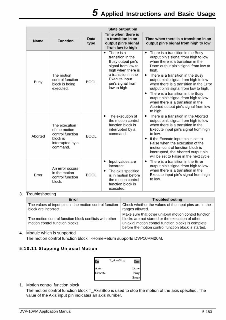
5 Applied Instructions and Basic Usage
DVP-10PM Application Manual 5-183
State output pin
Name Function Data type
Time when there is a transition in an
output pin’s signal from low to high
Time when there is a transition in an output pin’s signal from high to low
Busy
The motion control function block is being executed.
BOOL
There is a transition in the Busy output pin’s signal from low to high when there is a transition in the Execute input pin’s signal from low to high.
There is a transition in the Busy output pin’s signal from high to low when there is a transition in the Done output pin’s signal from low to high.
There is a transition in the Busy output pin’s signal from high to low when there is a transition in the Error output pin’s signal from low to high.
There is a transition in the Busy output pin’s signal from high to low when there is a transition in the Aborted output pin’s signal from low to high.
Aborted
The execution of the motion control function block is interrupted by a command.
BOOL
The execution of the motion control function block is interrupted by a command.
There is a transition in the Aborted output pin’s signal from high to low when there is a transition in the Execute input pin’s signal from high to low.
If the Execute input pin is set to False when the execution of the motion control function block is interrupted, the Aborted output pin will be set to False in the next cycle.
Error
An error occurs in the motion control function block.
BOOL
Input values are incorrect.
The axis specified is in motion before the motion control function block is executed.
There is a transition in the Error output pin’s signal from high to low when there is a transition in the Execute input pin’s signal from high to low.
3. Troubleshooting Error Troubleshooting
The values of input pins in the motion control function block are incorrect.
Check whether the values of the input pins are in the ranges allowed.
The motion control function block conflicts with other motion control function blocks.
Make sure that other uniaxial motion control function blocks are not started or the execution of other uniaxial motion control function blocks is complete before the motion control function block is started.
4. Module which is supported The motion control function block T-HomeReturn supports DVP10PM00M.
5.10.11 Stopping Uniaxial Motion
1. Motion control function block
The motion control function block T_AxisStop is used to stop the motion of the axis specified. The value of the Axis input pin indicates an axis number.
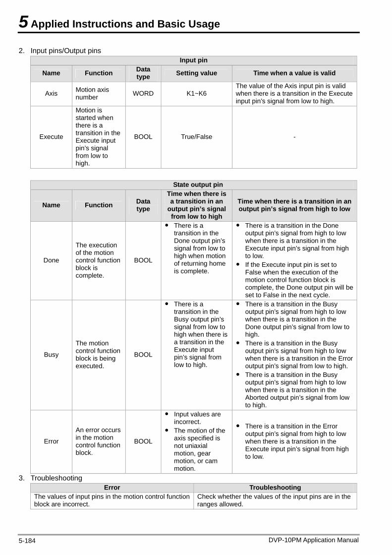
5 Applied Instructions and Basic Usage
2. Input pins/Output pins Input pin
Name Function Data type Setting value Time when a value is valid
Axis Motion axis number WORD K1~K6
The value of the Axis input pin is valid when there is a transition in the Execute input pin’s signal from low to high.
Execute
Motion is started when there is a transition in the Execute input pin’s signal from low to high.
BOOL True/False -
State output pin
Name Function Data type
Time when there is a transition in an
output pin’s signal from low to high
Time when there is a transition in an output pin’s signal from high to low
Done
The execution of the motion control function block is complete.
BOOL
There is a transition in the Done output pin’s signal from low to high when motion of returning home is complete.
There is a transition in the Done output pin’s signal from high to low when there is a transition in the Execute input pin’s signal from high to low.
If the Execute input pin is set to False when the execution of the motion control function block is complete, the Done output pin will be set to False in the next cycle.
Busy
The motion control function block is being executed.
BOOL
There is a transition in the Busy output pin’s signal from low to high when there is a transition in the Execute input pin’s signal from low to high.
There is a transition in the Busy output pin’s signal from high to low when there is a transition in the Done output pin’s signal from low to high.
There is a transition in the Busy output pin’s signal from high to low when there is a transition in the Error output pin’s signal from low to high.
There is a transition in the Busy output pin’s signal from high to low when there is a transition in the Aborted output pin’s signal from low to high.
Error
An error occurs in the motion control function block.
BOOL
Input values are incorrect.
The motion of the axis specified is not uniaxial motion, gear motion, or cam motion.
There is a transition in the Error output pin’s signal from high to low when there is a transition in the Execute input pin’s signal from high to low.
3. Troubleshooting Error Troubleshooting
The values of input pins in the motion control function block are incorrect.
Check whether the values of the input pins are in the ranges allowed.
DVP-10PM Application Manual 5-184
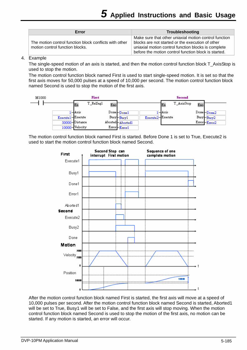
5 Applied Instructions and Basic Usage
DVP-10PM Application Manual 5-185
Error Troubleshooting
The motion control function block conflicts with other motion control function blocks.
Make sure that other uniaxial motion control function blocks are not started or the execution of other uniaxial motion control function blocks is complete before the motion control function block is started.
4. Example The single-speed motion of an axis is started, and then the motion control function block T_AxisStop is used to stop the motion. The motion control function block named First is used to start single-speed motion. It is set so that the first axis moves for 50,000 pulses at a speed of 10,000 per second. The motion control function block named Second is used to stop the motion of the first axis.
The motion control function block named First is started. Before Done 1 is set to True, Execute2 is used to start the motion control function block named Second.
After the motion control function block named First is started, the first axis will move at a speed of 10,000 pulses per second. After the motion control function block named Second is started, Aborted1 will be set to True, Busy1 will be set to False, and the first axis will stop moving. When the motion control function block named Second is used to stop the motion of the first axis, no motion can be started. If any motion is started, an error will occur.
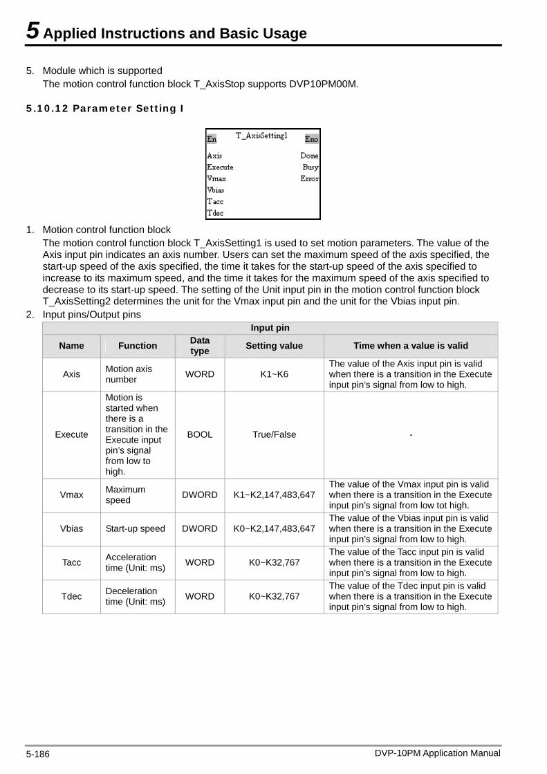
5 Applied Instructions and Basic Usage
5. Module which is supported The motion control function block T_AxisStop supports DVP10PM00M.
5.10.12 Parameter Setting I
1. Motion control function block
The motion control function block T_AxisSetting1 is used to set motion parameters. The value of the Axis input pin indicates an axis number. Users can set the maximum speed of the axis specified, the start-up speed of the axis specified, the time it takes for the start-up speed of the axis specified to increase to its maximum speed, and the time it takes for the maximum speed of the axis specified to decrease to its start-up speed. The setting of the Unit input pin in the motion control function block T_AxisSetting2 determines the unit for the Vmax input pin and the unit for the Vbias input pin.
2. Input pins/Output pins Input pin
Name Function Data type Setting value Time when a value is valid
Axis Motion axis number WORD K1~K6
The value of the Axis input pin is valid when there is a transition in the Execute input pin’s signal from low to high.
Execute
Motion is started when there is a transition in the Execute input pin’s signal from low to high.
BOOL True/False -
Vmax Maximum speed DWORD K1~K2,147,483,647
The value of the Vmax input pin is valid when there is a transition in the Execute input pin’s signal from low tot high.
Vbias Start-up speed DWORD K0~K2,147,483,647 The value of the Vbias input pin is valid when there is a transition in the Execute input pin’s signal from low to high.
Tacc Acceleration time (Unit: ms) WORD K0~K32,767
The value of the Tacc input pin is valid when there is a transition in the Execute input pin’s signal from low to high.
Tdec Deceleration time (Unit: ms) WORD K0~K32,767
The value of the Tdec input pin is valid when there is a transition in the Execute input pin’s signal from low to high.
DVP-10PM Application Manual 5-186
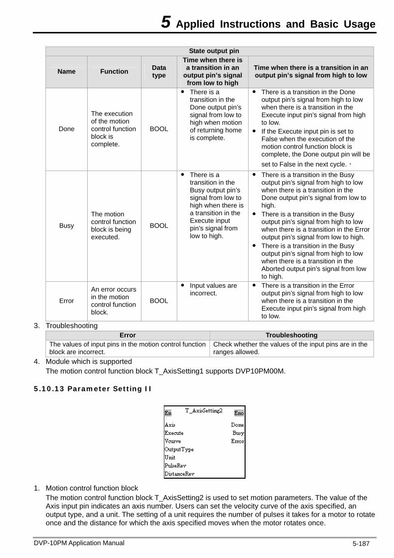
5 Applied Instructions and Basic Usage
State output pin
Name Function Data type
Time when there is a transition in an
output pin’s signal from low to high
Time when there is a transition in an output pin’s signal from high to low
Done
The execution of the motion control function block is complete.
BOOL
There is a transition in the Done output pin’s signal from low to high when motion of returning home is complete.
There is a transition in the Done output pin’s signal from high to low when there is a transition in the Execute input pin’s signal from high to low.
If the Execute input pin is set to False when the execution of the motion control function block is complete, the Done output pin will be set to False in the next cycle.。
Busy
The motion control function block is being executed.
BOOL
There is a transition in the Busy output pin’s signal from low to high when there is a transition in the Execute input pin’s signal from low to high.
There is a transition in the Busy output pin’s signal from high to low when there is a transition in the Done output pin’s signal from low to high.
There is a transition in the Busy output pin’s signal from high to low when there is a transition in the Error output pin’s signal from low to high.
There is a transition in the Busy output pin’s signal from high to low when there is a transition in the Aborted output pin’s signal from low to high.
Error
An error occurs in the motion control function block.
BOOL
Input values are incorrect.
There is a transition in the Error output pin’s signal from high to low when there is a transition in the Execute input pin’s signal from high to low.
3. Troubleshooting Error Troubleshooting
The values of input pins in the motion control function block are incorrect.
Check whether the values of the input pins are in the ranges allowed.
4. Module which is supported The motion control function block T_AxisSetting1 supports DVP10PM00M.
5.10.13 Parameter Setting II
1. Motion control function block
The motion control function block T_AxisSetting2 is used to set motion parameters. The value of the Axis input pin indicates an axis number. Users can set the velocity curve of the axis specified, an output type, and a unit. The setting of a unit requires the number of pulses it takes for a motor to rotate once and the distance for which the axis specified moves when the motor rotates once.
DVP-10PM Application Manual 5-187
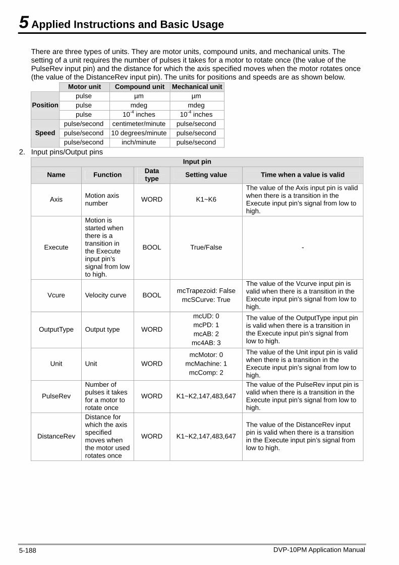
5 Applied Instructions and Basic Usage
There are three types of units. They are motor units, compound units, and mechanical units. The setting of a unit requires the number of pulses it takes for a motor to rotate once (the value of the PulseRev input pin) and the distance for which the axis specified moves when the motor rotates once (the value of the DistanceRev input pin). The units for positions and speeds are as shown below. Motor unit Compound unit Mechanical unit
pulse µm µm pulse mdeg mdeg Position pulse 10-4 inches 10-4 inches
pulse/second centimeter/minute pulse/second pulse/second 10 degrees/minute pulse/second Speed pulse/second inch/minute pulse/second
2. Input pins/Output pins Input pin
Name Function Data type Setting value Time when a value is valid
Axis Motion axis number WORD K1~K6
The value of the Axis input pin is valid when there is a transition in the Execute input pin’s signal from low to high.
Execute
Motion is started when there is a transition in the Execute input pin’s signal from low to high.
BOOL True/False -
Vcure Velocity curve BOOL mcTrapezoid: False mcSCurve: True
The value of the Vcurve input pin is valid when there is a transition in the Execute input pin’s signal from low to high.
OutputType Output type WORD
mcUD: 0 mcPD: 1 mcAB: 2
mc4AB: 3
The value of the OutputType input pin is valid when there is a transition in the Execute input pin’s signal from low to high.
Unit Unit WORD mcMotor: 0
mcMachine: 1 mcComp: 2
The value of the Unit input pin is valid when there is a transition in the Execute input pin’s signal from low to high.
PulseRev
Number of pulses it takes for a motor to rotate once
WORD K1~K2,147,483,647
The value of the PulseRev input pin is valid when there is a transition in the Execute input pin’s signal from low to high.
DistanceRev
Distance for which the axis specified moves when the motor used rotates once
WORD K1~K2,147,483,647
The value of the DistanceRev input pin is valid when there is a transition in the Execute input pin’s signal from low to high.
DVP-10PM Application Manual 5-188
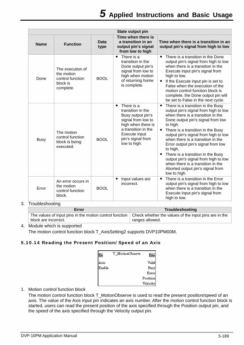
5 Applied Instructions and Basic Usage
State output pin
Name Function Data type
Time when there is a transition in an
output pin’s signal from low to high
Time when there is a transition in an output pin’s signal from high to low
Done
The execution of the motion control function block is complete.
BOOL
There is a transition in the Done output pin’s signal from low to high when motion of returning home is complete.
There is a transition in the Done output pin’s signal from high to low when there is a transition in the Execute input pin’s signal from high to low.
If the Execute input pin is set to False when the execution of the motion control function block is complete, the Done output pin will be set to False in the next cycle.
Busy
The motion control function block is being executed.
BOOL
There is a transition in the Busy output pin’s signal from low to high when there is a transition in the Execute input pin’s signal from low to high.
There is a transition in the Busy output pin’s signal from high to low when there is a transition in the Done output pin’s signal from low to high.
There is a transition in the Busy output pin’s signal from high to low when there is a transition in the Error output pin’s signal from low to high.
There is a transition in the Busy output pin’s signal from high to low when there is a transition in the Aborted output pin’s signal from low to high.
Error
An error occurs in the motion control function block.
BOOL
Input values are incorrect.
There is a transition in the Error output pin’s signal from high to low when there is a transition in the Execute input pin’s signal from high to low.
3. Troubleshooting Error Troubleshooting
The values of input pins in the motion control function block are incorrect.
Check whether the values of the input pins are in the ranges allowed.
4. Module which is supported The motion control function block T_AxisSetting2 supports DVP10PM00M.
5.10.14 Reading the Present Position/Speed of an Axis
1. Motion control function block
The motion control function block T_MotionObserve is used to read the present position/speed of an axis. The value of the Axis input pin indicates an axis number. After the motion control function block is started, users can read the present position of the axis specified through the Position output pin, and the speed of the axis specified through the Velocity output pin.
DVP-10PM Application Manual 5-189
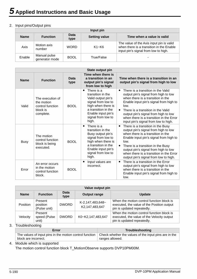
5 Applied Instructions and Basic Usage
2. Input pins/Output pins Input pin
Name Function Data type Setting value Time when a value is valid
Axis Motion axis number WORD K1~K6
The value of the Axis input pin is valid when there is a transition in the Enable input pin’s signal from low to high.
Enable Manual pulse generator mode BOOL True/False -
State output pin
Name Function Data type
Time when there is a transition in an
output pin’s signal from low to high
Time when there is a transition in an output pin’s signal from high to low
Valid
The execution of the motion control function block is complete.
BOOL
There is a transition in the Valid output pin’s signal from low to high when there is a transition in the Enable input pin’s signal from low to high.
There is a transition in the Valid output pin’s signal from high to low when there is a transition in the Enable input pin’s signal from high to low.
There is a transition in the Valid output pin’s signal from high to low when there is a transition in the Error input pin’s signal from low to high.
Busy
The motion control function block is being executed.
BOOL
There is a transition in the Busy output pin’s signal from low to high when there is a transition in the Enable input pin’s signal from low to high.
There is a transition in the Busy output pin’s signal from high to low when there is a transition in the Enable input pin’s signal from high to low.
There is a transition in the Busy output pin’s signal from high to low when there is a transition in the Error output pin’s signal from low to high.
Error
An error occurs in the motion control function block.
BOOL
Input values are incorrect.
There is a transition in the Error output pin’s signal from high to low when there is a transition in the Enable input pin’s signal from high to low.
Value output pin
Name Function Data type Output range Update
Position Present position (Pulse unit)
DWORD K-2,147,483,648~ K2,147,483,647
When the motion control function block is executed, the value of the Position output pin is updated repeatedly.
Velocity Present speed (Pulse unit)
DWORD K0~K2,147,483,647 When the motion control function block is executed, the value of the Velocity output pin is updated repeatedly.
3. Troubleshooting Error Troubleshooting
The values of input pins in the motion control function block are incorrect.
Check whether the values of the input pins are in the ranges allowed.
4. Module which is supported The motion control function block T_MotionObserve supports DVP10PM00M.
DVP-10PM Application Manual 5-190
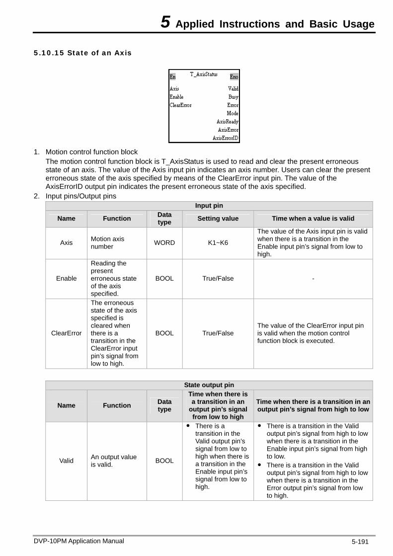
5 Applied Instructions and Basic Usage
5.10.15 State of an Axis
1. Motion control function block
The motion control function block is T_AxisStatus is used to read and clear the present erroneous state of an axis. The value of the Axis input pin indicates an axis number. Users can clear the present erroneous state of the axis specified by means of the ClearError input pin. The value of the AxisErrorID output pin indicates the present erroneous state of the axis specified.
2. Input pins/Output pins Input pin
Name Function Data type Setting value Time when a value is valid
Axis Motion axis number WORD K1~K6
The value of the Axis input pin is valid when there is a transition in the Enable input pin’s signal from low to high.
Enable
Reading the present erroneous state of the axis specified.
BOOL True/False -
ClearError
The erroneous state of the axis specified is cleared when there is a transition in the ClearError input pin’s signal from low to high.
BOOL True/False The value of the ClearError input pin is valid when the motion control function block is executed.
State output pin
Name Function Data type
Time when there is a transition in an
output pin’s signal from low to high
Time when there is a transition in an output pin’s signal from high to low
Valid An output value is valid. BOOL
There is a transition in the Valid output pin’s signal from low to high when there is a transition in the Enable input pin’s signal from low to high.
There is a transition in the Valid output pin’s signal from high to low when there is a transition in the Enable input pin’s signal from high to low.
There is a transition in the Valid output pin’s signal from high to low when there is a transition in the Error output pin’s signal from low to high.
DVP-10PM Application Manual 5-191
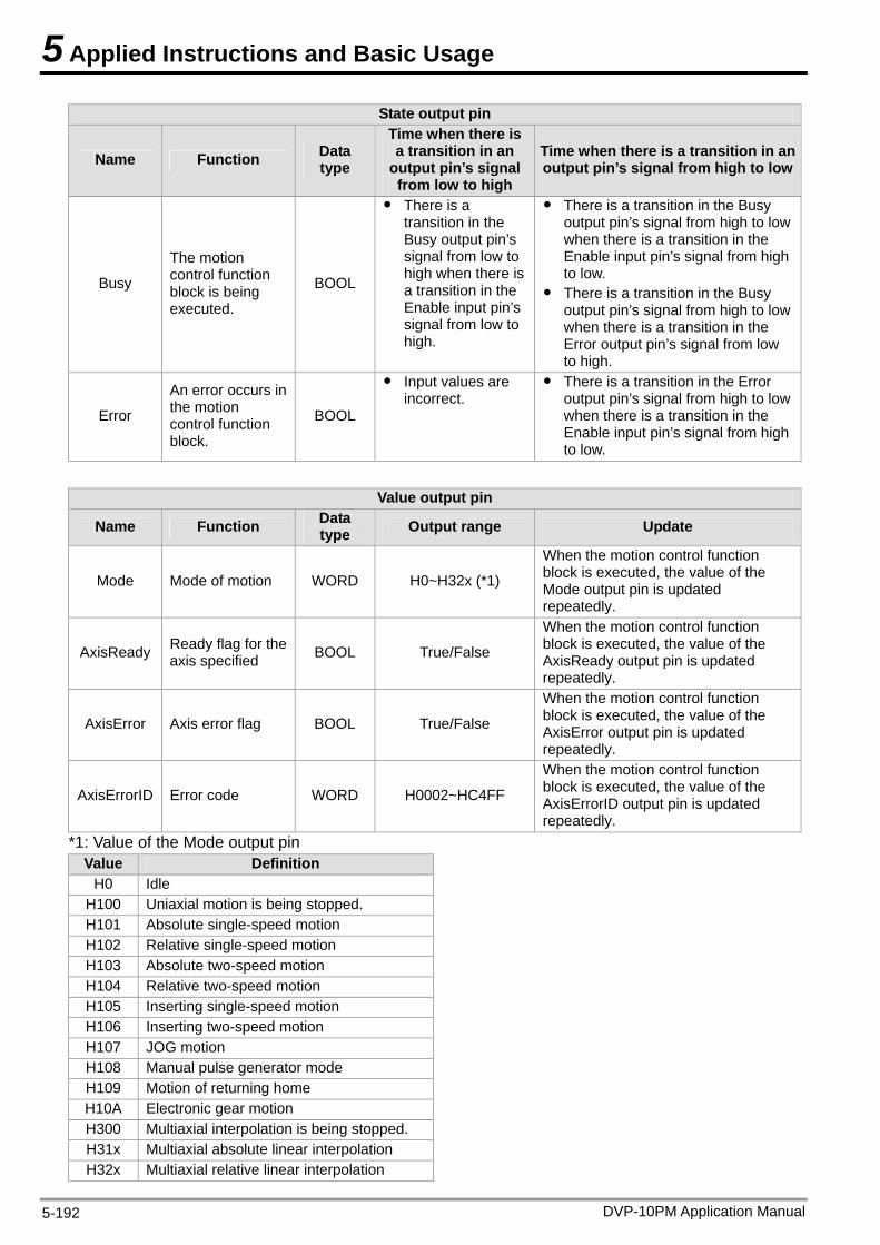
5 Applied Instructions and Basic Usage
DVP-10PM Application Manual 5-192
State output pin
Name Function Data type
Time when there is a transition in an
output pin’s signal from low to high
Time when there is a transition in an output pin’s signal from high to low
Busy
The motion control function block is being executed.
BOOL
There is a transition in the Busy output pin’s signal from low to high when there is a transition in the Enable input pin’s signal from low to high.
There is a transition in the Busy output pin’s signal from high to low when there is a transition in the Enable input pin’s signal from high to low.
There is a transition in the Busy output pin’s signal from high to low when there is a transition in the Error output pin’s signal from low to high.
Error
An error occurs in the motion control function block.
BOOL
Input values are incorrect.
There is a transition in the Error output pin’s signal from high to low when there is a transition in the Enable input pin’s signal from high to low.
Value output pin
Name Function Data type Output range Update
Mode Mode of motion WORD H0~H32x (*1)
When the motion control function block is executed, the value of the Mode output pin is updated repeatedly.
AxisReady Ready flag for the axis specified BOOL True/False
When the motion control function block is executed, the value of the AxisReady output pin is updated repeatedly.
AxisError Axis error flag BOOL True/False
When the motion control function block is executed, the value of the AxisError output pin is updated repeatedly.
AxisErrorID Error code WORD H0002~HC4FF
When the motion control function block is executed, the value of the AxisErrorID output pin is updated repeatedly.
*1: Value of the Mode output pin Value Definition
H0 Idle H100 Uniaxial motion is being stopped. H101 Absolute single-speed motion H102 Relative single-speed motion H103 Absolute two-speed motion H104 Relative two-speed motion H105 Inserting single-speed motion H106 Inserting two-speed motion H107 JOG motion H108 Manual pulse generator mode H109 Motion of returning home H10A Electronic gear motion H300 Multiaxial interpolation is being stopped. H31x Multiaxial absolute linear interpolation H32x Multiaxial relative linear interpolation
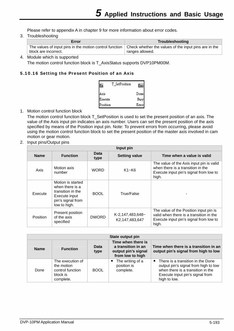
5 Applied Instructions and Basic Usage
Please refer to appendix A in chapter 9 for more information about error codes. 3. Troubleshooting
Error Troubleshooting The values of input pins in the motion control function block are incorrect.
Check whether the values of the input pins are in the ranges allowed.
4. Module which is supported The motion control function block is T_AxisStatus supports DVP10PM00M.
5.10.16 Setting the Present Position of an Axis
1. Motion control function block
The motion control function block T_SetPosition is used to set the present position of an axis. The value of the Axis input pin indicates an axis number. Users can set the present position of the axis specified by means of the Position input pin. Note: To prevent errors from occurring, please avoid using the motion control function block to set the present position of the master axis involved in cam motion or gear motion.
2. Input pins/Output pins Input pin
Name Function Data type Setting value Time when a value is valid
Axis Motion axis number WORD K1~K6
The value of the Axis input pin is valid when there is a transition in the Execute input pin’s signal from low to high.
Execute
Motion is started when there is a transition in the Execute input pin’s signal from low to high.
BOOL True/False -
Position Present position of the axis specified
DWORD K-2,147,483,648~ K2,147,483,647
The value of the Position input pin is valid when there is a transition in the Execute input pin’s signal from low to high.
State output pin
Name Function Data type
Time when there is a transition in an
output pin’s signal from low to high
Time when there is a transition in an output pin’s signal from high to low
Done
The execution of the motion control function block is complete.
BOOL
The writing of a position is complete.
There is a transition in the Done output pin’s signal from high to low when there is a transition in the Execute input pin’s signal from high to low.
DVP-10PM Application Manual 5-193
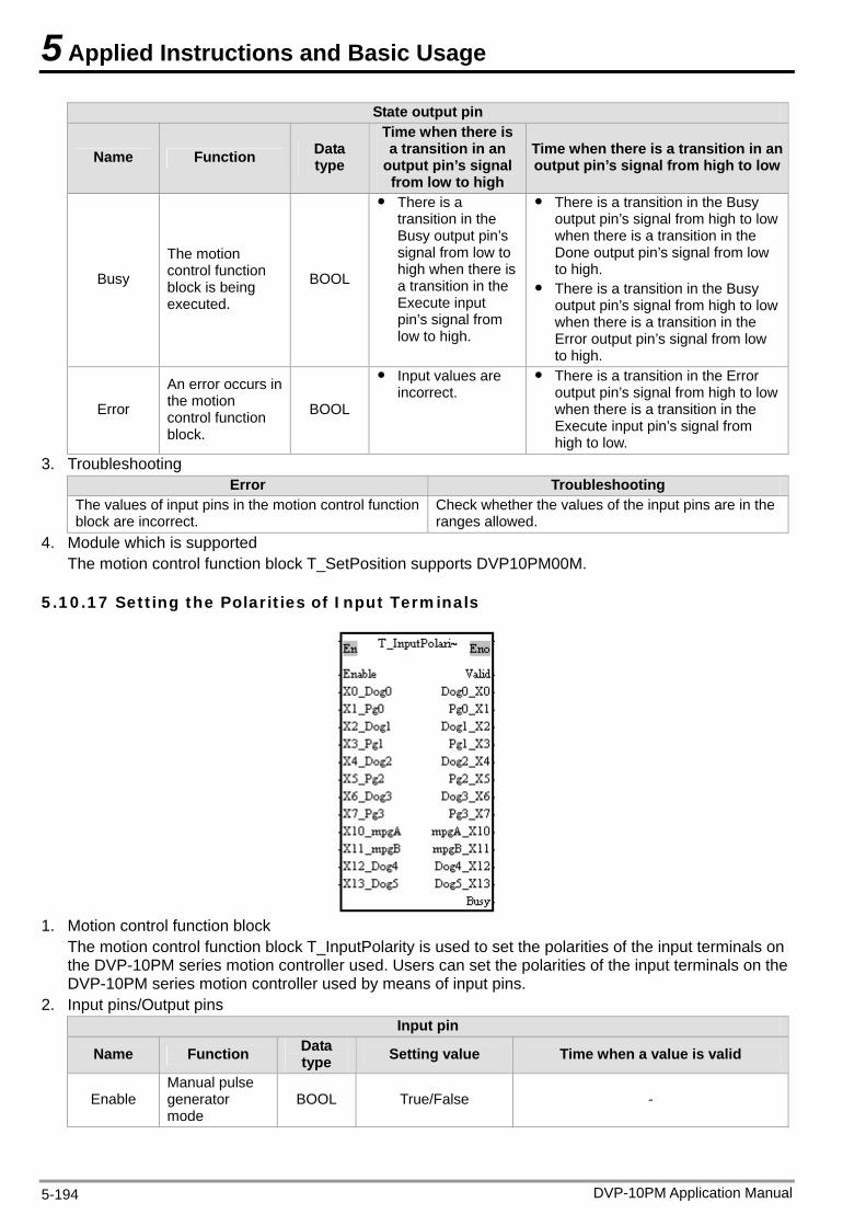
5 Applied Instructions and Basic Usage
DVP-10PM Application Manual 5-194
State output pin
Name Function Data type
Time when there is a transition in an
output pin’s signal from low to high
Time when there is a transition in an output pin’s signal from high to low
Busy
The motion control function block is being executed.
BOOL
There is a transition in the Busy output pin’s signal from low to high when there is a transition in the Execute input pin’s signal from low to high.
There is a transition in the Busy output pin’s signal from high to low when there is a transition in the Done output pin’s signal from low to high.
There is a transition in the Busy output pin’s signal from high to low when there is a transition in the Error output pin’s signal from low to high.
Error
An error occurs in the motion control function block.
BOOL
Input values are incorrect.
There is a transition in the Error output pin’s signal from high to low when there is a transition in the Execute input pin’s signal from high to low.
3. Troubleshooting Error Troubleshooting
The values of input pins in the motion control function block are incorrect.
Check whether the values of the input pins are in the ranges allowed.
4. Module which is supported The motion control function block T_SetPosition supports DVP10PM00M.
5.10.17 Setting the Polarities of Input Terminals
1. Motion control function block
The motion control function block T_InputPolarity is used to set the polarities of the input terminals on the DVP-10PM series motion controller used. Users can set the polarities of the input terminals on the DVP-10PM series motion controller used by means of input pins.
2. Input pins/Output pins Input pin
Name Function Data type Setting value Time when a value is valid
Enable Manual pulse generator mode
BOOL True/False -
5 Applied Instructions and Basic Usage
DVP-10PM Application Manual 5-195
Input pin
Name Function Data type Setting value Time when a value is valid
X0_Dog0 Polarity BOOL X1_Pg0 Polarity BOOL
X2_Dog1 Polarity BOOL X3_Pg1 Polarity BOOL
X4_Dog2 Polarity BOOL X5_Pg2 Polarity BOOL
X6_Dog3 Polarity BOOL X7_Pg3 Polarity BOOL
X10_mpgA Polarity BOOL X11_mpgB Polarity BOOL X12_Dog4 Polarity BOOL X13_Dog5 Polarity BOOL
mcNO: False mcNC: True
When the motion control function block is executed, the values of the input pins are updated repeatedly.
State output pin
Name Function Data type
Time when there is a transition in an
output pin’s signal from low to high
Time when there is a transition in an output pin’s signal from high to low
Valid
The execution of the motion control function block is complete.
BOOL
There is a transition in the Valid output pin’s signal from low to high when there is a transition in the Enable input pin’s signal from low to high.
There is a transition in the Valid output pin’s signal from high to low when there is a transition in the Enable input pin’s signal from high to low.
Busy
The motion control function block is being executed.
BOOL
There is a transition in the Busy output pin’s signal from low to high when there is a transition in the Enable input pin’s signal from low to high.
There is a transition in the Busy output pin’s signal from high to low when there is a transition in the Enable input pin’s signal from high to low.
Dog0_X0 Polarity BOOL Pg0_ X1 Polarity BOOL Dog1_X2 Polarity BOOL Pg1_X3 Polarity BOOL
Dog2_X4 Polarity BOOL Pg2_X5 Polarity BOOL
Dog3_X6 Polarity BOOL Pg3_X7 Polarity BOOL
mpgA_X10 Polarity BOOL mpgB_X11 Polarity BOOL Dog4_X12 Polarity BOOL
Dog5_X13 Polarity BOOL
When input pins are set to True, and the input terminals are OFF, there are transitions in these output pins’ signals from low to high.
When input pins are set to False, and the input terminals are ON, there are transitions in these output pins’ signals from low to high.
When input pins are set to True, and the input terminals are ON, there are transitions in these output pins’ signals from high to low.
When input pins are set to False, and the input terminals are OFF, there are transitions in these output pins’ signals from high to low.
There are transitions in these output pins’ signals from high to low when there is a transition in the Enable input pin’s signal from high to low.
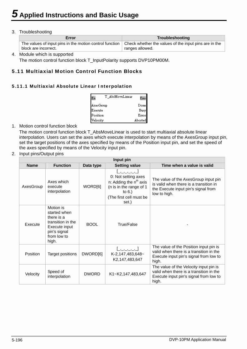
5 Applied Instructions and Basic Usage
3. Troubleshooting Error Troubleshooting
The values of input pins in the motion control function block are incorrect.
Check whether the values of the input pins are in the ranges allowed.
4. Module which is supported The motion control function block T_InputPolarity supports DVP10PM00M.
5.11 Multiaxial Motion Control Function Blocks
5.11.1 Multiaxial Absolute Linear Interpolation
1. Motion control function block
The motion control function block T_AbsMoveLinear is used to start multiaxial absolute linear interpolation. Users can set the axes which execute interpolation by means of the AxesGroup input pin, set the target positions of the axes specified by means of the Position input pin, and set the speed of the axes specified by means of the Velocity input pin.
2. Input pins/Output pins Input pin
Name Function Data type Setting value Time when a value is valid
AxesGroup Axes which execute interpolation
WORD[6]
[_,_,_,_,_,_] 0: Not setting axes
n: Adding the nth axis (n is in the range of 1
to 6.) (The first cell must be
set.)
The value of the AxesGroup input pin is valid when there is a transition in the Execute input pin’s signal from low to high.
Execute
Motion is started when there is a transition in the Execute input pin’s signal from low to high.
BOOL True/False -
Position Target positions DWORD[6][_,_,_,_,_,_]
K-2,147,483,648~ K2,147,483,647
The value of the Position input pin is valid when there is a transition in the Execute input pin’s signal from low to high.
Velocity Speed of interpolation DWORD K1~K2,147,483,647
The value of the Velocity input pin is valid when there is a transition in the Execute input pin’s signal from low to high.
DVP-10PM Application Manual 5-196
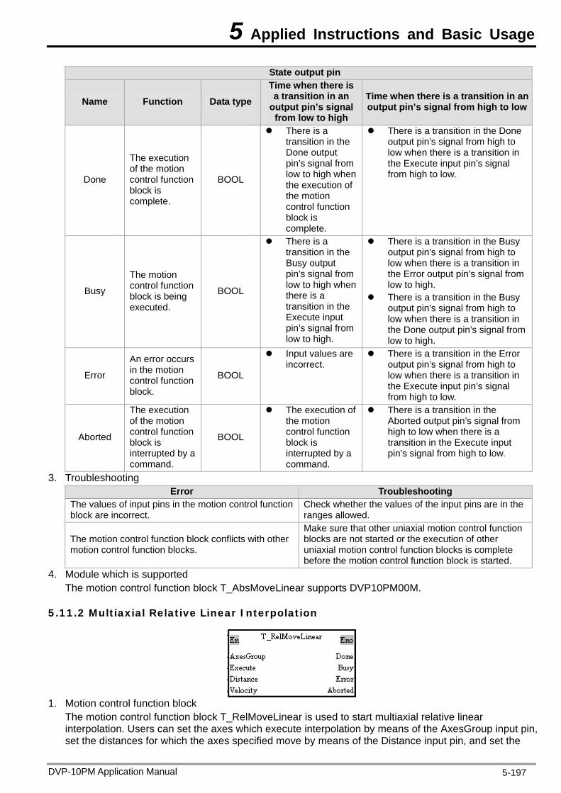
5 Applied Instructions and Basic Usage
State output pin
Name Function Data typeTime when there is a transition in an
output pin’s signal from low to high
Time when there is a transition in an output pin’s signal from high to low
Done
The execution of the motion control function block is complete.
BOOL
There is a transition in the Done output pin’s signal from low to high when the execution of the motion control function block is complete.
There is a transition in the Done output pin’s signal from high to low when there is a transition in the Execute input pin’s signal from high to low.
Busy
The motion control function block is being executed.
BOOL
There is a transition in the Busy output pin’s signal from low to high when there is a transition in the Execute input pin’s signal from low to high.
There is a transition in the Busy output pin’s signal from high to low when there is a transition in the Error output pin’s signal from low to high.
There is a transition in the Busy output pin’s signal from high to low when there is a transition in the Done output pin’s signal from low to high.
Error
An error occurs in the motion control function block.
BOOL
Input values are incorrect.
There is a transition in the Error output pin’s signal from high to low when there is a transition in the Execute input pin’s signal from high to low.
Aborted
The execution of the motion control function block is interrupted by a command.
BOOL
The execution of the motion control function block is interrupted by a command.
There is a transition in the Aborted output pin’s signal from high to low when there is a transition in the Execute input pin’s signal from high to low.
3. Troubleshooting Error Troubleshooting
The values of input pins in the motion control function block are incorrect.
Check whether the values of the input pins are in the ranges allowed.
The motion control function block conflicts with other motion control function blocks.
Make sure that other uniaxial motion control function blocks are not started or the execution of other uniaxial motion control function blocks is complete before the motion control function block is started.
4. Module which is supported The motion control function block T_AbsMoveLinear supports DVP10PM00M.
5.11.2 Multiaxial Relative Linear Interpolation
1. Motion control function block
The motion control function block T_RelMoveLinear is used to start multiaxial relative linear interpolation. Users can set the axes which execute interpolation by means of the AxesGroup input pin, set the distances for which the axes specified move by means of the Distance input pin, and set the
DVP-10PM Application Manual 5-197
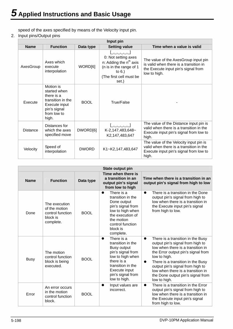
5 Applied Instructions and Basic Usage
speed of the axes specified by means of the Velocity input pin. 2. Input pins/Output pins
Input pin Name Function Data type Setting value Time when a value is valid
AxesGroup Axes which execute interpolation
WORD[6]
[_,_,_,_,_,_] 0: Not setting axes
n: Adding the nth axis (n is in the range of 1
to 6.) (The first cell must be
set.)
The value of the AxesGroup input pin is valid when there is a transition in the Execute input pin’s signal from low to high.
Execute
Motion is started when there is a transition in the Execute input pin’s signal from low to high.
BOOL True/False -
Distance Distances for which the axes specified move
DWORD[6][_,_,_,_,_,_]
K-2,147,483,648~ K2,147,483,647
The value of the Distance input pin is valid when there is a transition in the Execute input pin’s signal from low to high.
Velocity Speed of interpolation DWORD K1~K2,147,483,647
The value of the Velocity input pin is valid when there is a transition in the Execute input pin’s signal from low to high.
State output pin
Name Function Data type Time when there is a transition in an
output pin’s signal from low to high
Time when there is a transition in an output pin’s signal from high to low
Done
The execution of the motion control function block is complete.
BOOL
There is a transition in the Done output pin’s signal from low to high when the execution of the motion control function block is complete.
There is a transition in the Done output pin’s signal from high to low when there is a transition in the Execute input pin’s signal from high to low.
Busy
The motion control function block is being executed.
BOOL
There is a transition in the Busy output pin’s signal from low to high when there is a transition in the Execute input pin’s signal from low to high.
There is a transition in the Busy output pin’s signal from high to low when there is a transition in the Error output pin’s signal from low to high.
There is a transition in the Busy output pin’s signal from high to low when there is a transition in the Done output pin’s signal from low to high.
Error
An error occurs in the motion control function block.
BOOL
Input values are incorrect.
There is a transition in the Error output pin’s signal from high to low when there is a transition in the Execute input pin’s signal from high to low.
DVP-10PM Application Manual 5-198
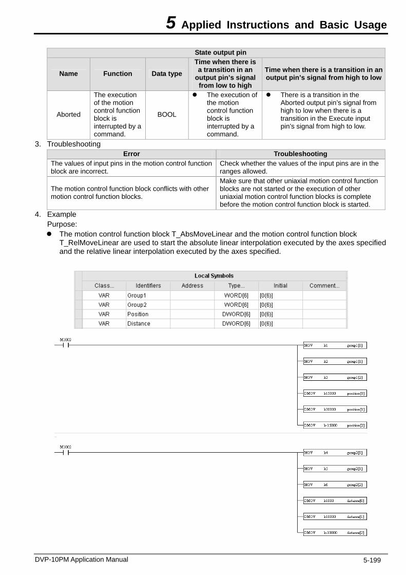
5 Applied Instructions and Basic Usage
DVP-10PM Application Manual 5-199
State output pin
Name Function Data typeTime when there is a transition in an
output pin’s signal from low to high
Time when there is a transition in an output pin’s signal from high to low
Aborted
The execution of the motion control function block is interrupted by a command.
BOOL
The execution of the motion control function block is interrupted by a command.
There is a transition in the Aborted output pin’s signal from high to low when there is a transition in the Execute input pin’s signal from high to low.
3. Troubleshooting Error Troubleshooting
The values of input pins in the motion control function block are incorrect.
Check whether the values of the input pins are in the ranges allowed.
The motion control function block conflicts with other motion control function blocks.
Make sure that other uniaxial motion control function blocks are not started or the execution of other uniaxial motion control function blocks is complete before the motion control function block is started.
4. Example Purpose: The motion control function block T_AbsMoveLinear and the motion control function block
T_RelMoveLinear are used to start the absolute linear interpolation executed by the axes specified and the relative linear interpolation executed by the axes specified.
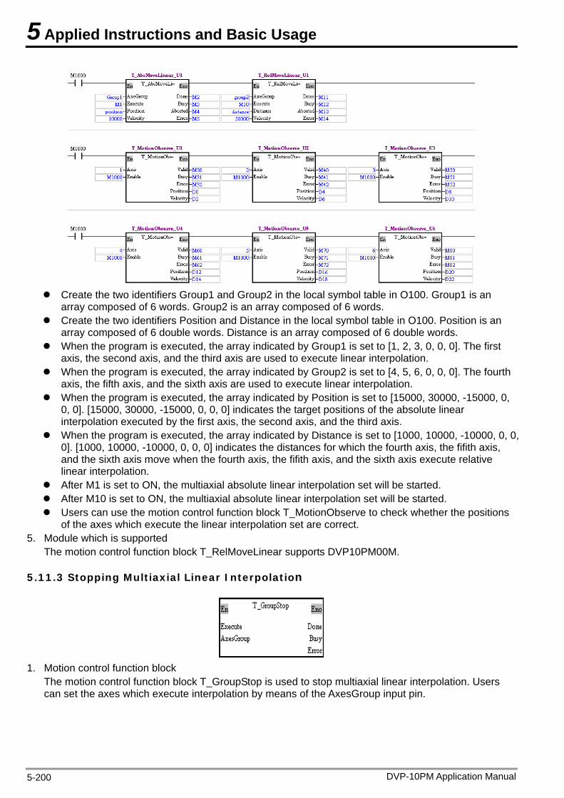
5 Applied Instructions and Basic Usage
Create the two identifiers Group1 and Group2 in the local symbol table in O100. Group1 is an
array composed of 6 words. Group2 is an array composed of 6 words. Create the two identifiers Position and Distance in the local symbol table in O100. Position is an
array composed of 6 double words. Distance is an array composed of 6 double words. When the program is executed, the array indicated by Group1 is set to [1, 2, 3, 0, 0, 0]. The first
axis, the second axis, and the third axis are used to execute linear interpolation. When the program is executed, the array indicated by Group2 is set to [4, 5, 6, 0, 0, 0]. The fourth
axis, the fifth axis, and the sixth axis are used to execute linear interpolation. When the program is executed, the array indicated by Position is set to [15000, 30000, -15000, 0,
0, 0]. [15000, 30000, -15000, 0, 0, 0] indicates the target positions of the absolute linear interpolation executed by the first axis, the second axis, and the third axis.
When the program is executed, the array indicated by Distance is set to [1000, 10000, -10000, 0, 0, 0]. [1000, 10000, -10000, 0, 0, 0] indicates the distances for which the fourth axis, the fifith axis, and the sixth axis move when the fourth axis, the fifith axis, and the sixth axis execute relative linear interpolation.
After M1 is set to ON, the multiaxial absolute linear interpolation set will be started. After M10 is set to ON, the multiaxial absolute linear interpolation set will be started. Users can use the motion control function block T_MotionObserve to check whether the positions
of the axes which execute the linear interpolation set are correct. 5. Module which is supported
The motion control function block T_RelMoveLinear supports DVP10PM00M.
5.11.3 Stopping Multiaxial Linear Interpolation
1. Motion control function block
The motion control function block T_GroupStop is used to stop multiaxial linear interpolation. Users can set the axes which execute interpolation by means of the AxesGroup input pin.
DVP-10PM Application Manual 5-200
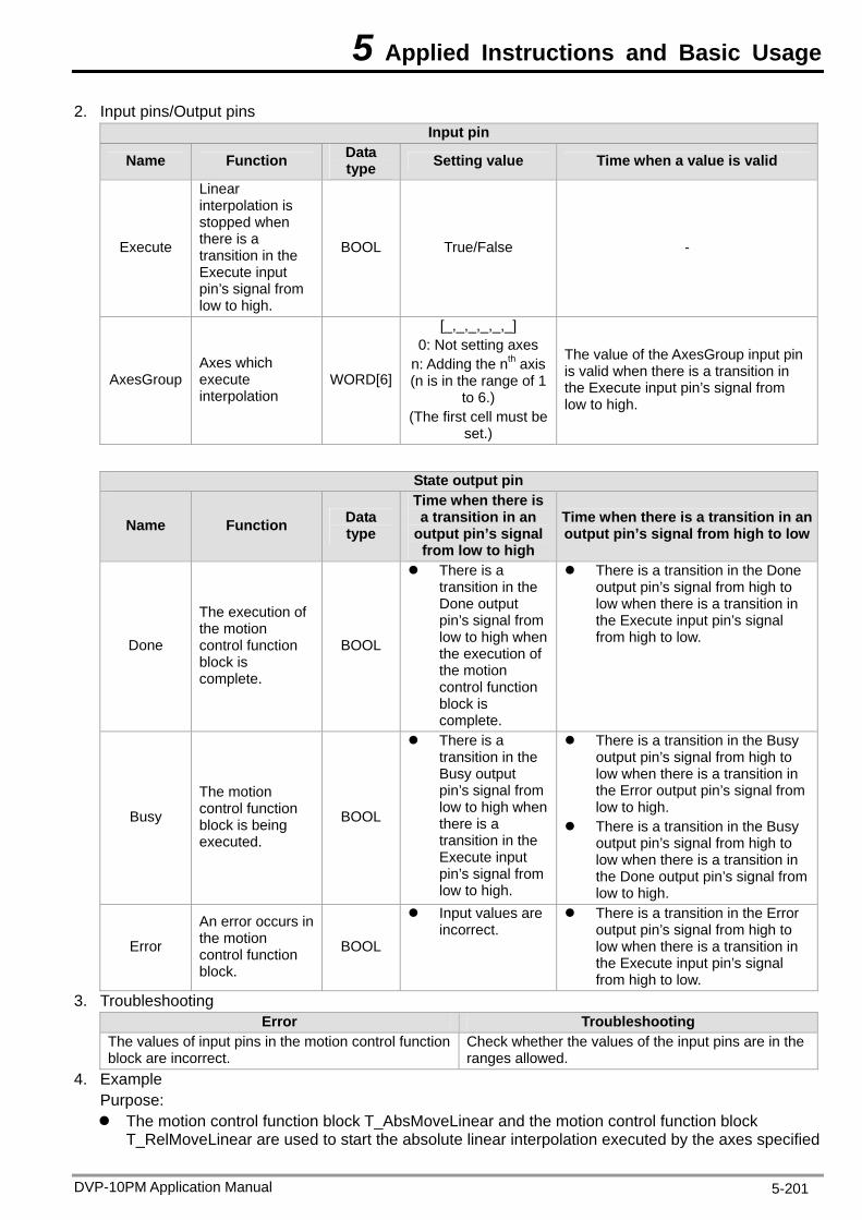
5 Applied Instructions and Basic Usage
2. Input pins/Output pins Input pin
Name Function Data type Setting value Time when a value is valid
Execute
Linear interpolation is stopped when there is a transition in the Execute input pin’s signal from low to high.
BOOL True/False -
AxesGroup Axes which execute interpolation
WORD[6]
[_,_,_,_,_,_] 0: Not setting axes
n: Adding the nth axis (n is in the range of 1
to 6.) (The first cell must be
set.)
The value of the AxesGroup input pin is valid when there is a transition in the Execute input pin’s signal from low to high.
State output pin
Name Function Data type
Time when there is a transition in an
output pin’s signal from low to high
Time when there is a transition in an output pin’s signal from high to low
Done
The execution of the motion control function block is complete.
BOOL
There is a transition in the Done output pin’s signal from low to high when the execution of the motion control function block is complete.
There is a transition in the Done output pin’s signal from high to low when there is a transition in the Execute input pin’s signal from high to low.
Busy
The motion control function block is being executed.
BOOL
There is a transition in the Busy output pin’s signal from low to high when there is a transition in the Execute input pin’s signal from low to high.
There is a transition in the Busy output pin’s signal from high to low when there is a transition in the Error output pin’s signal from low to high.
There is a transition in the Busy output pin’s signal from high to low when there is a transition in the Done output pin’s signal from low to high.
Error
An error occurs in the motion control function block.
BOOL
Input values are incorrect.
There is a transition in the Error output pin’s signal from high to low when there is a transition in the Execute input pin’s signal from high to low.
3. Troubleshooting Error Troubleshooting
The values of input pins in the motion control function block are incorrect.
Check whether the values of the input pins are in the ranges allowed.
4. Example Purpose: The motion control function block T_AbsMoveLinear and the motion control function block
T_RelMoveLinear are used to start the absolute linear interpolation executed by the axes specified
DVP-10PM Application Manual 5-201
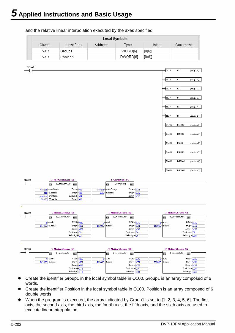
5 Applied Instructions and Basic Usage
and the relative linear interpolation executed by the axes specified.
C he identifier Group1 in the local symbol table in O100. Group1 is an array composed of 6 words. Create the identi
reate t
fier Position in the local symbol table in O100. Position is an array composed of 6 double words.
When the program is executed, the array indicated by Group1 is set to [1, 2, 3, 4, 5, 6]. The first axis, the second axis, the third axis, the fourth axis, the fifth axis, and the sixth axis are used to execute linear interpolation.
DVP-10PM Application Manual 5-202
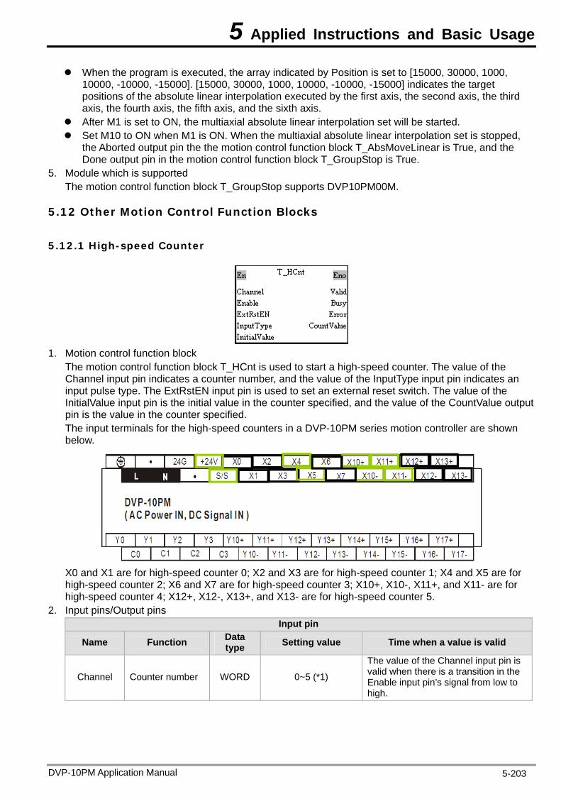
5 Applied Instructions and Basic Usage
DVP-10PM Application Manual 5-203
When the program is executed, the array indicated by Position is set to [15000, 30000, 1000, 10000, -10000, -15000]. [15000, 30000, 1000, 10000, -10000, -15000] indicates the target
is, the third
lation set is stopped, e the motion control function block T_AbsMoveLinear is True, and the
ue. 5. Module which is supported
DVP10PM00M.
5.12 Other Motion Control Function Blocks
5.12.1 High-speed Counter
positions of the absolute linear interpolation executed by the first axis, the second axaxis, the fourth axis, the fifth axis, and the sixth axis.
After M1 is set to ON, the multiaxial absolute linear interpolation set will be started. Set M10 to ON when M1 is ON. When the multiaxial absolute linear interpo
the Aborted output pin thDone output pin in the motion control function block T_GroupStop is Tr
The motion control function block T_GroupStop supports
Motion control function block The motion control function block T_HCnt is used to start a high-speed counter. The value of the Channel input pin indicates a counter number, and the value of the InputType input pin indicates an input pulse type. The ExtRstEN input pin
1.
is used to set an external reset switch. The value of the ut
e value in the counter specified. The input terminals for the high-speed counters in a DVP-10PM series motion controller are shown below.
InitialValue input pin is the initial value in the counter specified, and the value of the CountValue outppin is th
X0 and X1 are for high-speed counter 0; X2 and X3 are for high-speed counter 1; X4 and X5 are for
6 and X7 are for high-speed counter 3; X10+, X10-, X11+, and X11- are for high-speed counter 4; X12+, X12-, X13+, and r high-speed counter 5.
2. Input pins/Output pins
high-speed counter 2; XX13- are fo
Input pin
Name Function Data type Setting value Time when a value is valid
Cha nel Counter number WORD 0~5 (*1) hen there is a transition in the Enable input pin’s signal from low to n
The value of the Channel input pin is valid w
high.
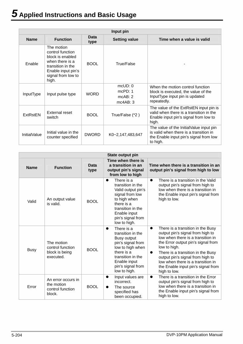
5 Applied Instructions and Basic Usage
DVP-10PM Application Manual 5-204
Input pin
Name Function Data type Setting value Time when a value is valid
Enable
input pin’s signal from low to high.
BOOL True/False -
The motion control function block is enabled when there is a transition in the Enable
InputType Input pulse type WORD mcAB: 2
n uted, the value of the
mcUD: 0 mcPD: 1
mc4AB: 3
When the motion control functioblock is execInputType input pin is updated repeatedly.
ExtRstEN External reset switch BOOL True/False (*2 )
s hen there is a transition in the
The value of the ExtRstEN input pin ivalid wEnable input pin’s signal from low to high.
InitialValue Initial value in the counter specified DWORD K0~2,147,483,647 hen there is a transition in
the Enable input pin’s signal from low to high.
The value of the InitialValue input pin is valid w
State output pin
Name Function Data type
Time when there is a transition in an
output pin’s signal from low to high
Time when there is a transition in an output pin’s signal from high to low
Valid An output value is valid. BOOL
n low
re is a transition in the Enable input pin’s signal from high to low.
There is a transition in the Valid output pisignal fromto high when there is a transition in the Enable input
’s
There is a transition in the Valid output pin’s signal from high to low when the
pin’s signallow to high.
from
Busy tion block is being executed.
BOOL
re is a transition in
re is a transition in
The motion control func
There is a transition in the Busy output pin’s signalow to high whenthere is a transition in the Enable input
l from
the Error output pin’s signal from low to high.
There is a transition in the Busy output pin’s signal from high to low when the
pin’s signal from low to high.
There is a transition in the Busy output pin’s signal from high to low when the
the Enable input pin’s signal fromhigh to low.
Error
n tion
control function block.
BOOL specified has been occupied.
re is a transition in the Enable input pin’s signal from high to low.
An error occurs ithe mo
Input values arincorrect.
The source
e There is a transition in the Error output pin’s signal from high to low when the
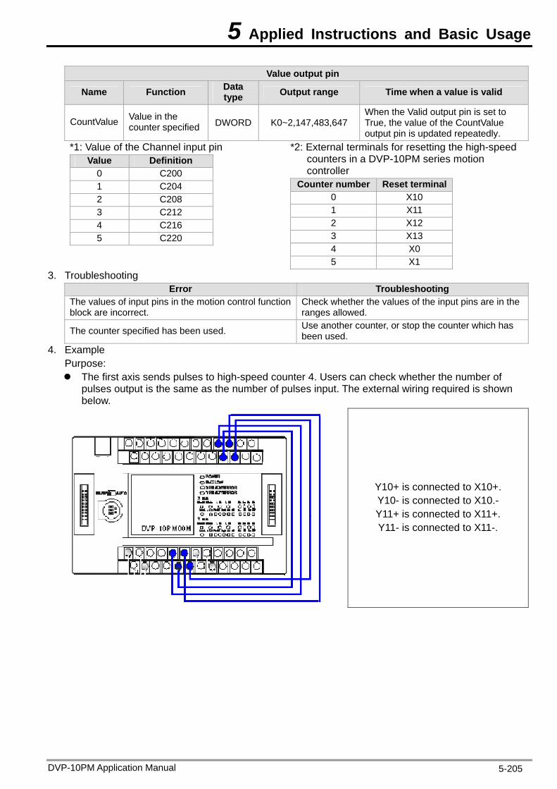
5 Applied Instructions and Basic Usage
DVP-10PM Application Manual 5-205
Value output pin
Name Function Data type Output range Time when a value is valid
CountValue Value in the counter specified DWORD K0~
ly. 2,147,483,647 True, the value of the CountValue
output pin is updated repeated
When the Valid output pin is set to
*1: Va of the Cha put pin lue nnel inVa e lu De n finitio
0 C200 1 C204 2 C208 3 C212 4 C216 5 C220
*2: rminals for resetting the high-speed V motion
controller
External tecounters in a D P-10PM series
Counter number Rese inal t term0 X10 1 X11 2 X12 3 X13 4 X0 5 X1
3. Troubleshooting Error Troubleshooting
The values of input pins in the motion cblock are incorrect.
ontrol function ed.
Check whether the values of the input pins are in theranges allow
The counter specified has been used. Use another counter, or stop the counter which has been used.
4. Example Purpose: The first axis sends pulses to high-speed counter 4. Users can check whether the number of
pulses output is the same as the number of pulses input. The external wiring required is shown below.
Y10+ is connected to X10+. Y10- is connected to X10.- Y11+ is connected to X11+. Y11- is connected to X11-.
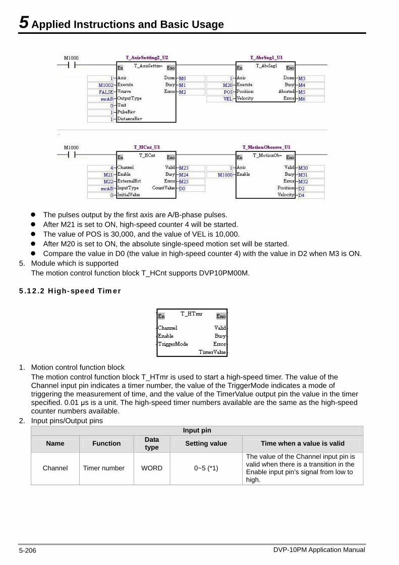
5 Applied Instructions and Basic Usage
The pulses output by the first axis are A/B-phase pulses. After M21 is set to ON, high-speed counter 4 will be started. The value of POS is 30,000, and the value of VEL is 10,000. After M20 is set to ON, the absolute single-speed motion set will be started. Compare the value in D0 (the value in high-speed counter 4) with the value in D2 when M3 is ON.
5. Module which is supported The motion control function block T_HCnt supports DVP10PM00M.
5.12.2 High-speed Timer
1. Motion control function block
The motion control function block T_HTmr is used to start a high-speed timer. The value of the Channel input pin indicates a timer number, the value of the TriggerMode indicates a mode of triggering the measurement of time, and the value of the TimerValue output pin the value in the timer specified. 0.01 μs is a unit. The high-speed timer numbers available are the same as the high-speed counter numbers available.
2. Input pins/Output pins Input pin
Name Function Data type Setting value Time when a value is valid
Channel Timer number WORD 0~5 (*1)
The value of the Channel input pin is valid when there is a transition in the Enable input pin’s signal from low to high.
DVP-10PM Application Manual 5-206
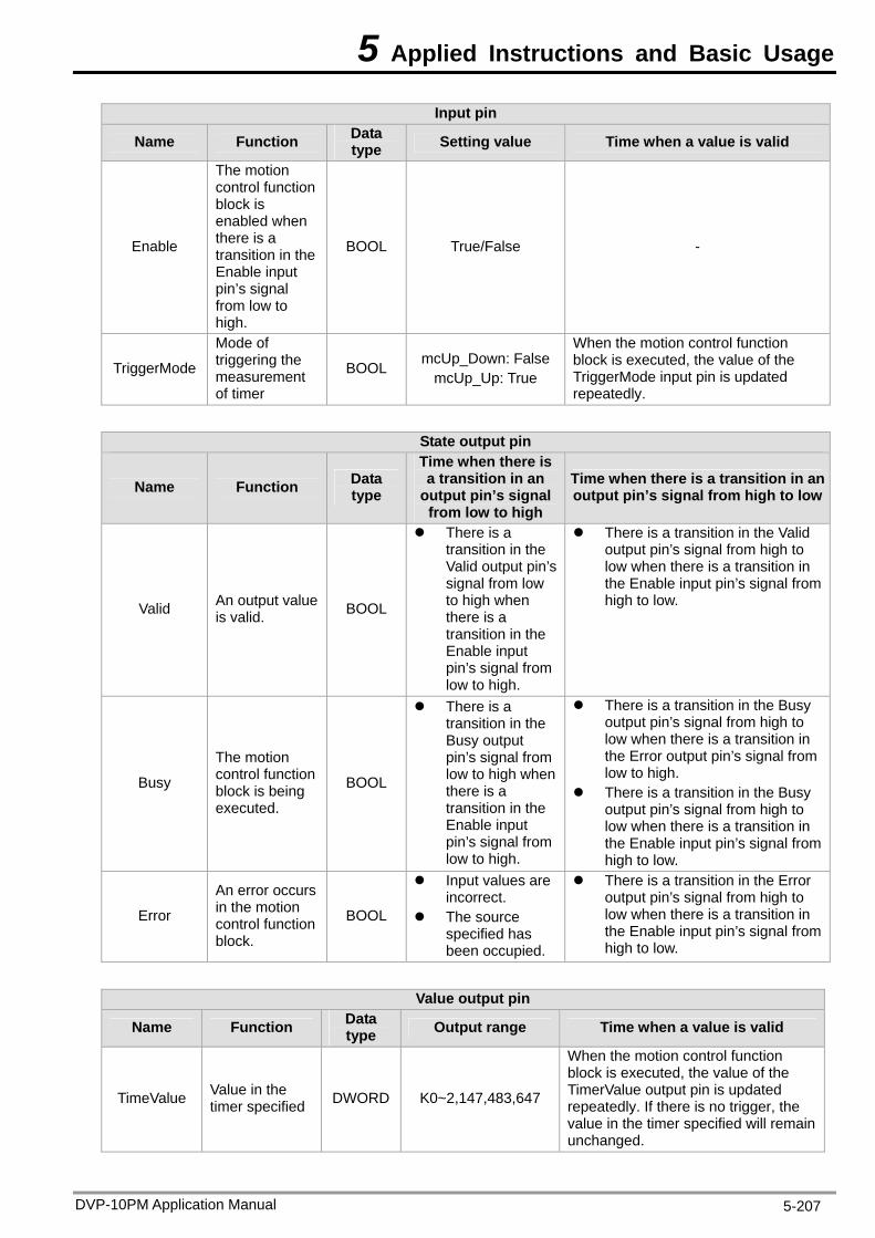
5 Applied Instructions and Basic Usage
DVP-10PM Application Manual 5-207
Input pin
Name Function Data type Setting value Time when a value is valid
Enable
The motion control function block is enabled when there is a transition in the Enable input pin’s signal from low to high.
BOOL True/False -
TriggerMode
Mode of triggering the measurement of timer
BOOL mcUp_Down: False mcUp_Up: True
When the motion control function block is executed, the value of the TriggerMode input pin is updated repeatedly.
State output pin
Name Function Data type
Time when there is a transition in an
output pin’s signal from low to high
Time when there is a transition in an output pin’s signal from high to low
Valid An output value is valid. BOOL
There is a transition in the Valid output pin’s signal from low to high when there is a transition in the Enable input pin’s signal from low to high.
There is a transition in the Valid output pin’s signal from high to low when there is a transition in the Enable input pin’s signal from high to low.
Busy
The motion control function block is being executed.
BOOL
There is a transition in the Busy output pin’s signal from low to high when there is a transition in the Enable input pin’s signal from low to high.
There is a transition in the Busy output pin’s signal from high to low when there is a transition in the Error output pin’s signal from low to high.
There is a transition in the Busy output pin’s signal from high to low when there is a transition in the Enable input pin’s signal from high to low.
Error
An error occurs in the motion control function block.
BOOL
Input values are incorrect.
The source specified has been occupied.
There is a transition in the Error output pin’s signal from high to low when there is a transition in the Enable input pin’s signal from high to low.
Value output pin
Name Function Data type Output range Time when a value is valid
TimeValue Value in the timer specified DWORD K0~2,147,483,647
When the motion control function block is executed, the value of the TimerValue output pin is updated repeatedly. If there is no trigger, the value in the timer specified will remain unchanged.
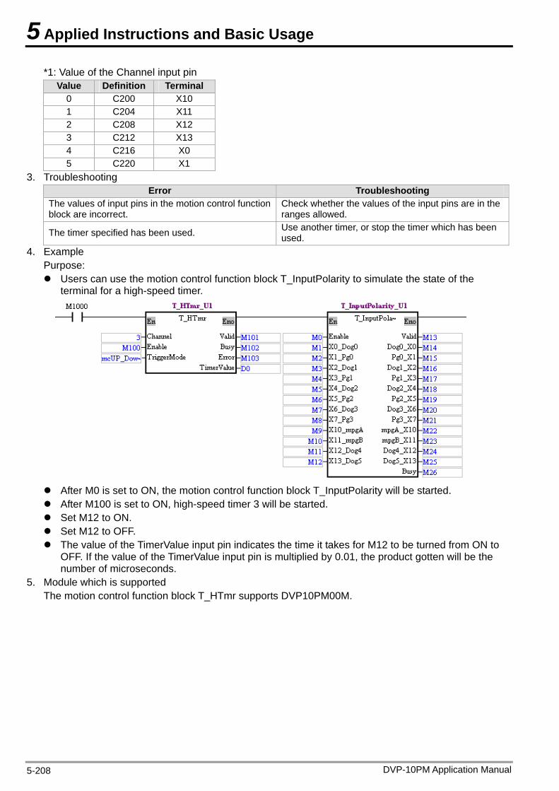
5 Applied Instructions and Basic Usage
*1: Value of the Channel input pin Value Definition Terminal
0 C200 X10 1 C204 X11 2 C208 X12 3 C212 X13 4 C216 X0 5 C220 X1
3. Troubleshooting Error Troubleshooting
The values of input pins in the motion control function block are incorrect.
Check whether the values of the input pins are in the ranges allowed.
The timer specified has been used. Use another timer, or stop the timer which has been used.
4. Example Purpose: Users can use the motion control function block T_InputPolarity to simulate the state of the
terminal for a high-speed timer.
After M0 is set to ON, the motion control function block T_InputPolarity will be started. After M100 is set to ON, high-speed timer 3 will be started. Set M12 to ON. Set M12 to OFF. The value of the TimerValue input pin indicates the time it takes for M12 to be turned from ON to
OFF. If the value of the TimerValue input pin is multiplied by 0.01, the product gotten will be the number of microseconds.
5. Module which is supported The motion control function block T_HTmr supports DVP10PM00M.
DVP-10PM Application Manual 5-208
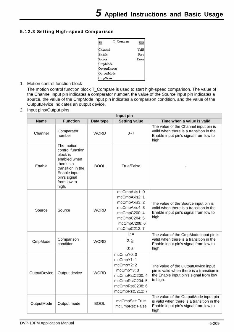
5 Applied Instructions and Basic Usage
DVP-10PM Application Manual 5-209
5.12.3 Setting High-speed Comparison
1. Motion control function block
ock T_Compare is used to start high-speed comparison. The value of
2.
The motion control function blthe Channel input pin indicates a comparator number, the value of the Source input pin indicates a source, the value of the CmpMode input pin indicates a comparison condition, and the value of the OutputDevice indicates an output device. Input pins/Output pins
Input pin Name Function Data type Setting value Time when a value is valid
Channel Co WORD 0~7
The v is mparator
number
alue of the Channel input pin valid when there is a transition in the Enable input pin’s signal from low to high.
Enable BOOL True/False -
The motion control function block is enabled when there is a transition in theEnable input pin’s signal from low to high.
Source Source WORD
mcCmpAxis1: 0
The value of the Source input pin is
mcCmpAxis2: 1 mcCmpAxis3: 2 mcCmpAxis4: 3 mcCmpC200: 4 mcCmpC204: 5 mcCmpC208: 6 mcCmpC212: 7
valid when there is a transition in theEnable input pin’s signal from low to high.
CmpMode Comparison WORD
The value of the CmpMode input pin is
condition
1: =
2: ≧
3: ≦
valid when there is a transition in the Enable input pin’s signal from low to high.
OutputDevice Output device WORD
mcCm
4
The value of the OutputDevice input n
pY0: 0mcCmpY1: 1 mcCmpY2: 2
mcCmpY3: 3mcCmpRstC200:mcCmpRstC204: 5mcCmpRstC208: 6mcCmpRstC212: 7
pin is valid when there is a transition ithe Enable input pin’s signal from low to high.
OutputMode Output mode BOOL mcCmpSet: True mcCmpRst: False
The value of the OutputMode input pin is valid when there is a transition in the Enable input pin’s signal from low to high.
5 Applied Instructions and Basic Usage
DVP-10PM Application Manual 5-210
Input pin Name Function Data type Setting value Time when a value is valid
CmpValue Value with which a source
DWORD K-2,147,483,647~
K2,147,483,647
is hen there is a transition in the
is compared
The value of the CmpValue input pin valid wEnable input pin’s signal from low to high.
State output pin
Name Function Data type
Time when there is a transition in an
output pin’s signal from low to high
Time when there is a transition in an output pin’s signal from high to low
Valid An output value is valid. BOOL
ut
output pin’s signal from high to
There is a transition in the Valid outpusignal from low to high when there is a transition in the Enable inppin’s signal fromlow to high.
t pin’s low when there is a transition in the Enable input pin’s signal fromhigh to low.
There is a transition in the Valid
Busy
The motion control function
g BOOL
he
he
There is a transition in the Busy output pin’s signal from high to
ignal from high to
block is beinexecuted.
There is a transition in tBusy outpupin’s signal fromlow to high wthere is a transition in the Enable inppin’s signal fromlow to high.
t
n
low when there is a transition in the Error output pin’s signal fromlow to high.
There is a transition in the Busy output pin’s s
ut
low when there is a transition in the Enable input pin’s signal fromhigh to low.
Error
An error occurs in the motion BOOL
as
ignal from high to
control function block.
Input values are incorrect.
The source specified hbeen occupied.
There is a transition in the Error output pin’s slow when there is a transition in the Enable input pin’s signal fromhigh to low.
Please note tha high-spe tat most.
cCmpAxis1: Present position of the first axis pAxis2: Present position of the second axis
Resetting C200 Resetting C204
t the number of ed comparators plus he number of high-speed capturers is 8
Source m mcCm mcCmpAxis3: Present position of the third axis mcCmpAxis4: Present position of the fourth axis mcCmpC200: Present value in C200 mcCmpC204: Present value in C204 mcCmpC204: Present value in C208 mcCmpC204: Present value in C212
Output device mcCmpY0: Y0 mcCmpY1: Y1 mcCmpY2: Y2 mcCmpY3: Y3 mcCmpRstC200: mcCmpRstC204: mcCmpRstC208: Resetting C208
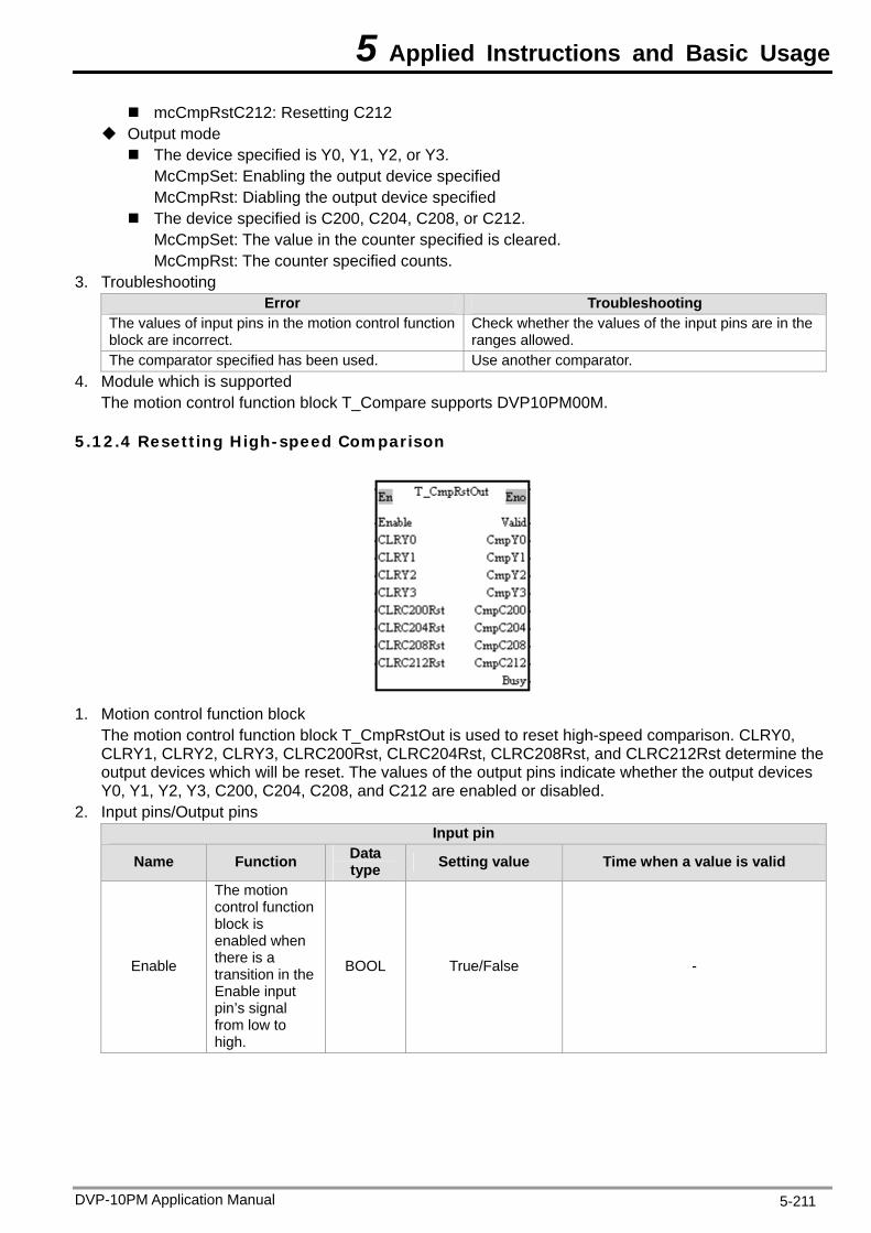
5 Applied Instructions and Basic Usage
DVP-10PM Application Manual 5-211
mcCmpRstC212: Resetting C212 Output mode The device specified is Y0, Y1, Y2, or Y3.
: Enabling the output device specified cified
2. cleared.
3. Trouble
McCmpSetMcCmpRst: Diabling the output device speThe device specified is C200, C204, C208, or C21McCmpSet: The value in the counter specified is McCmpRst: The counter specified counts. shooting
Error Troubleshooting The values of input pins in the motion control function block are incorrect.
Check whether the values of the input pins are in the ranges allowed.
The comparator specified has been used. Use another comparator. 4. Module which is supported
T pare supp
5.1
he motion control function block T_Com orts DVP10PM00M.
2.4 Resetting High-speed Comparison
1. Motion control function block The motion control function block T_CmpRstOut is used to r ed comparison. CLRY0,
C200Rst, CLRC204Rst, CLRC208Rst, and CLRC212Rst determine the s
2.
eset high-speCLRY1, CLRY2, CLRY3, CLRoutput devices which will be reset. The values of the output pins indicate whether the output deviceY0, Y1, Y2, Y3, C200, C204, C208, and C212 are enabled or disabled. Input pins/Output pins
Input pin
Name Function Data type Setting value Time when a value is valid
Enable
The motion co n
BOOL True/False -
ntrol functioblock is enabled when there is a transition in theEnable input pin’s signal from low to high.
5 Applied Instructions and Basic Usage
DVP-10PM Application Manual 5-212
Input pin
Name Function Data type Setting value Time when a value is valid
CL 0 RYCL 1 RYCLRY2 CLRY3
CL st RC200RCL st RC204R
CLRC208Rst
CLRC212Rst
Resetting the output devices
, BOOL True/False When the motion control function block is executed, the values of these
Y0, Y1, Y2, Y3C200, C204, C208, and C212
input pins are updated repeatedly.
State output pin
Name Function Data type
Time when there is a transition in an
output pin’s signal from low to high
Time when there is a transition in an output pin’s signal from high to low
Valid An output value is valid. BOOL
output pin’s signal from high to
There is a transition in the Valid outpusignal from low to high when there is a transition in the Enable input pin’s signal fromlow to high.
t pin’s low when there is a transition in the Enable input pin’s signal fromhigh to low.
There is a transition in the Valid
Busy
The motion control function
g BOOL
he There is a transition in the Busy
output pin’s signal from high to
ignal from high to
block is beinexecuted.
There is a transition in tBusy outpupin’s signal fromlow to high whenthere is a transition in the Enable input pin’s signal fromlow to high.
t
low when there is a transition in the Error output pin’s signal fromlow to high.
There is a transition in the Busy output pin’s s
low when there is a transition in the Enable input pin’s signal fromhigh to low.
Error
An error occurs in the motion BOOL
as
ignal from high to
control function block.
Input values are incorrect.
The source specified hbeen occupied.
There is a transition in the Error output pin’s slow when there is a transition in the Enable input pin’s signal fromhigh to low.
Value output pin
Name Function Data type Output range Time when a value is valid
CmpY0 CmpY1 CmpY2 CmpY3
C mpC200C mpC204CmpC208 CmpC212
States of the output devices Y0, Y1, Y2, Y3, C200, C204, C208, and C212
BOOL True/False
When the Valid output pin is set to True, the values of these output pins are updated repeatedly.
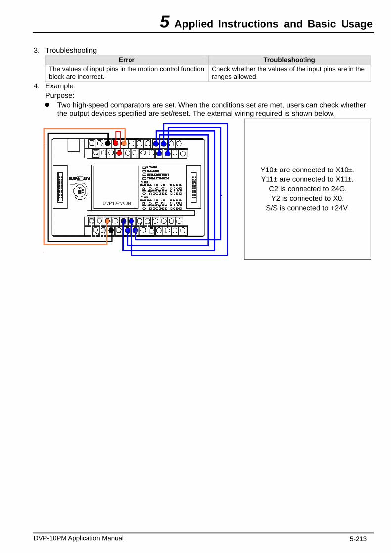
5 Applied Instructions and Basic Usage
DVP-10PM Application Manual 5-213
3. Troubleshooting Error Troubleshooting
The values of input pins in the motion control function block are incorrect.
Check whether the values of the input pins are in the ranges allowed.
4. Example Purpose: Two high-speed comparators are set. When the conditions set are met, users can check whether
the output devices specified are set/reset. The external wiring required is shown below.
Y10± are connected to X10±. Y11± are connected to X11±.
C2 is connected to 24G. Y2 is connected to X0.
S/S is connected to +24V.
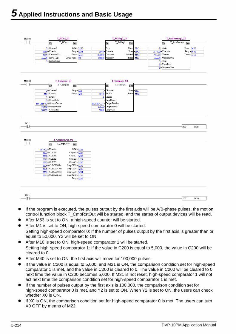
5 Applied Instructions and Basic Usage
DVP-10PM Application Manual 5-214
If the program is executed, the pulses output by the first axis will be A/B-phase pulses, the motion
control function block T_CmpRstOut will be started, and the states of output devices will be read. After M53 is set to ON, a high-speed counter will be started. After M1 is set to ON, high-speed comparator 0 will be started.
Setting high-speed comparator 0: If the number of pulses output by the first axis is greater than or equal to 50,000, Y2 will be set to ON.
After M10 is set to ON, high-speed comparator 1 will be started. Setting high-speed comparator 1: If the value in C200 is equal to 5,000, the value in C200 will be cleared to 0.
After M40 is set to ON, the first axis will move for 100,000 pulses. If the value in C200 is equal to 5,000, and M31 is ON, the comparison condition set for high-speed
comparator 1 is met, and the value in C200 is cleared to 0. The value in C200 will be cleared to 0 next time the value in C200 becomes 5,000. If M31 is not reset, high-speed comparator 1 will not act next time the comparison condition set for high-speed comparator 1 is met.
If the number of pulses output by the first axis is 100,000, the comparison condition set for high-speed comparator 0 is met, and Y2 is set to ON. When Y2 is set to ON, the users can check whether X0 is ON.
If X0 is ON, the comparison condition set for high-speed comparator 0 is met. The users can turn X0 OFF by means of M22.
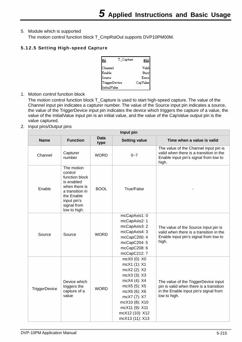
5 Applied Instructions and Basic Usage
DVP-10PM Application Manual 5-215
5. Module which is supported The motion control function block T_CmpRstOut supports DVP10PM00M.
5.12.5 Setting High-speed Capture
1. Motion control function block
The motion control function block T_Capture is used to start high-speed capture. The value of the Channel input pin indicates a capturer number. The value of the Source input pin indicates a source, the value of the TriggerDevice input pin indicates the device which triggers the capture of a value, the value of the InitialValue input pin is an initial value, and the value of the CapValue output pin is the value captured.
2. Input pins/Output pins Input pin
Name Function Data type Setting value Time when a value is valid
Channel Capturer number WORD 0~7
The value of the Channel input pin is valid when there is a transition in the Enable input pin’s signal from low to high.
Enable
The motion control function block is enabled when there is a transition in the Enable input pin’s signal from low to high.
BOOL True/False -
Source Source WORD mcCapC200: 4 Enable input pin’s signal from low to
mcCapAxis1: 0 mcCapAxis2: 1 mcCapAxis3: 2 mcCapAxis4: 3
The value of the Source inva
mcCapC204: 5
put pin is lid when there is a transition in the
high. mcCapC208: 6 mcCapC212: 7
TriggerDevice
Device which triggers the WORD
mcX2 (2): X2 mcX3 (3): X3 mcX4 (4): X4 mcX5 (5): X5
The value of the TriggerDevice input pin is valid when th
capture of a value
mcX6 (6): X6 mcX7 (7): X7
in the Enable input pin’s signal flow to high.
mcX0 (0): X0
mcX10 (8): X10
mcX12 (10): X12 mcX13 (11): X13
ere is a transition rom
mcX1 (1): X1
mcX11 (9): X11
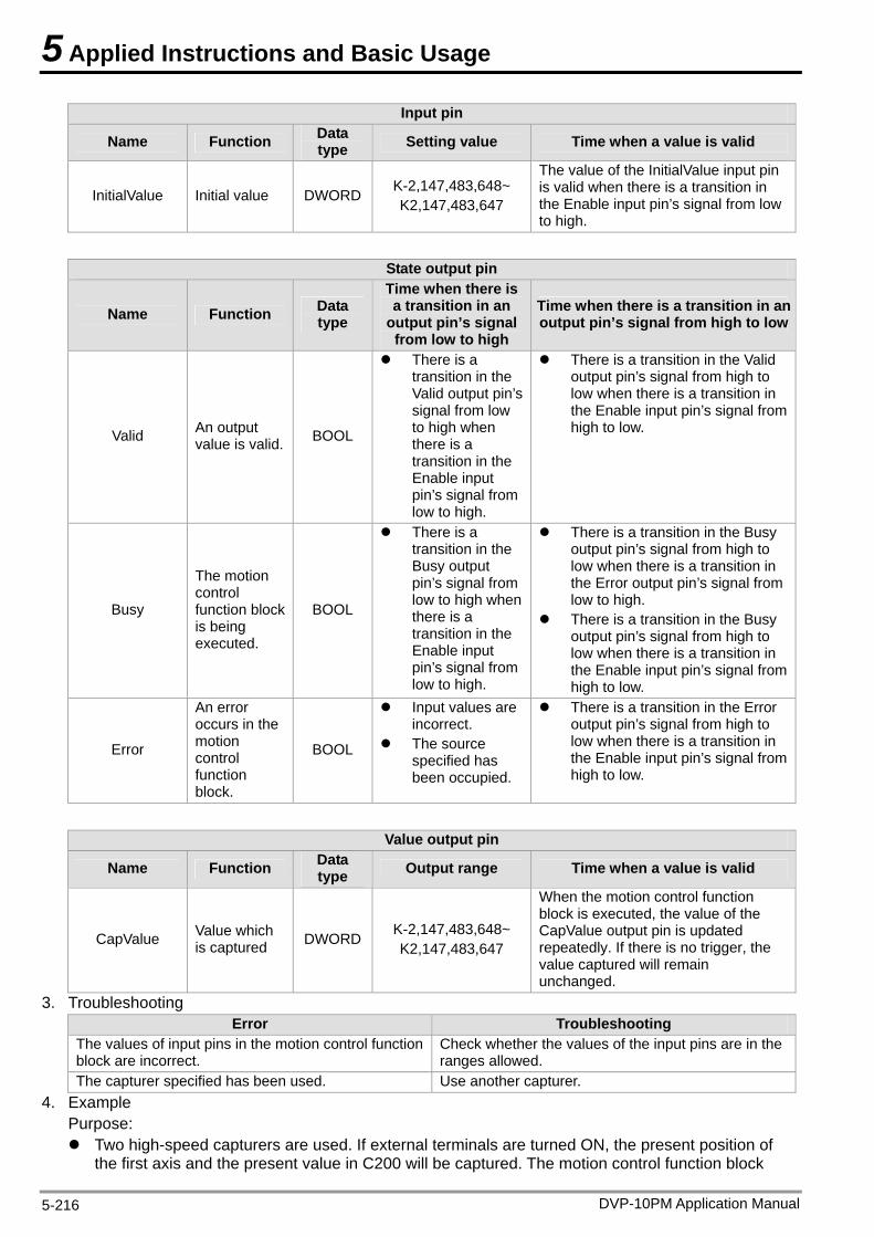
5 Applied Instructions and Basic Usage
DVP-10PM Application Manual 5-216
Input pin
Name Function Data type Setting value Time when a value is valid
InitialValue Initial value DWORD K-2,147,483,648~ K2,147,483,647
The value of the InitialValue input pin is valid when there is a transition in the Enable input pin’s signal from low to high.
State output pin
Name Function Data type
Time when there is a transition in an
output pin’s signal from low to high
Time when there is a transition in an output pin’s signal from high to low
Valid An output
There is a transition in the Valid output pin’s signal from low to high when
There is a transition in the Validoutput pin’s signal from high to low when there is a transition in the Enable input pin’s signal from high to low.
value is valid. BOOL there is a transition in the
put
Enable inpin’s signal from low to high.
Busy
on control
k
BOOL
There is a tranBusy output pin’s signal from low to high when there is a transition in the Enable input pin’s signal from
e Error output pin’s signal from
There is a transition in the Busy output pin’s signal from high to low when there is a transition in the Enable input pin’s signal from high to low.
The moti
function blocis beingexecuted.
sition in the
low to high.
There is a transition in the Busy output pin’s signal from high to low when there is a transition in thlow to high.
Error
e
function block.
BOOL
Input values are incorrect.
The source specified has
.
There is a transition in the Error output pin’s signal from high to low when there is a transition in the Enable input pin’s signal from high to low.
An error occurs in thmotion control
been occupied
Value output pin
Name Function Data type Output range Time when a value is valid
CapValue Value which is captured DWORD K
K
When the motion control function block is executed, the value of the CapValue output pin is updated repeatedly. If there is no trigger, the value captured will remain unchanged.
- ~ 2,147,483,6482,147,483,647
3. Troubleshooting Error Troubleshooting
T pu otio l functiblock are incorrec
ether d
he values of in t pins in the mt.
n contro on Check whranges allowe
the values of the input pins are in the.
The capturer spec as been used. er captuified h Use anoth rer. 4. Example
Purpose: Two high-speed capturers are used. If external terminals are turned ON, the present position of
the first axis and the present value in C200 will The motion control function block be captured.
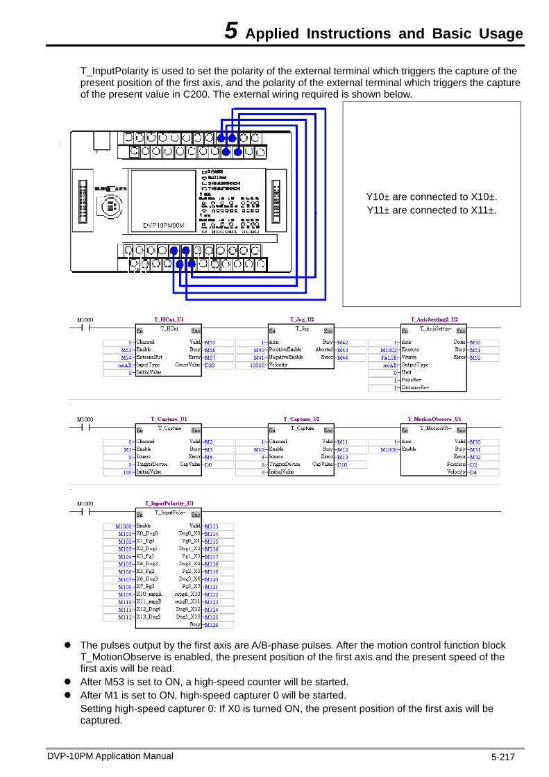
5 Applied Instructions and Basic Usage
DVP-10PM Application Manual 5-217
T_InputPolarity is used to set the polarity of the external terminal which triggers the capture of the p osition t axis, and the polarity of the external ter ture of the present value in C200. T ternal wiring required is shown
resent p of the firs minal which triggers the cap below. he ex
Y10± are connected to X10±. Y11± are connected to X11±.
The pulses output by the first axis are A/B-phase pulses. After the motion control function block io
read. ed counter wi
1 is set to ON, high-speed capturer 0 will be started. high-speed capturer 0: If X0 is turned ON, the present position of the first axis will be
T_MotionObserve is enabled, the present positfirst axis will be
n of the first axis and the present speed of the
After M53 is set to ON, a high-spe ll be started. After M
Settingcaptured.
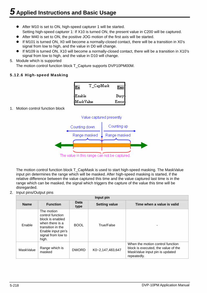
5 Applied Instructions and Basic Usage
DVP-10PM Application Manual 5-218
After M10 is set to ON, high-speed capturer 1 will be started. Setting high-speed capturer 1: If X10 is turned ON, the present value in C200 will be captured.
After M40 is set to ON, the positive JOG motion of the first axis will be started. If M101 is turned ON, X0 will become a normally-closed contact, there will be a transition in X0’s
signal from low to high, and the value in D0 will change. If M109 is turned ON, X10 will become a normally-closed contact, there will be a transition in X10’s
signal from low to high, and the value in D10 will change. 5. Module which is supported
The motion control function block T_Capture supports DVP10PM00M.
5.12.6 High-speed Masking
1. Motion control function block
The motion control function block T_CapMask is used to start high-speed masking. The MaskValue input pin determines the range which will be masked. After high-speed masking is started, if the relative difference between the value captured this time and the value captured last time is in the range which can be masked, the signal which triggers the capture of the value this time will be disregarded.
2. Input pins/Output pins Input pin
Name Function Data type Setting value Time when a value is valid
Enable
The motion control function block is enabled when there is a transition in the Enable input pin’s signal from low to high.
BOOL True/False -
MaskValue Range which is masked DWORD K0~2,147,483,647
When the motion control function block is executed, the value of the MaskValue input pin is updated repeatedly.
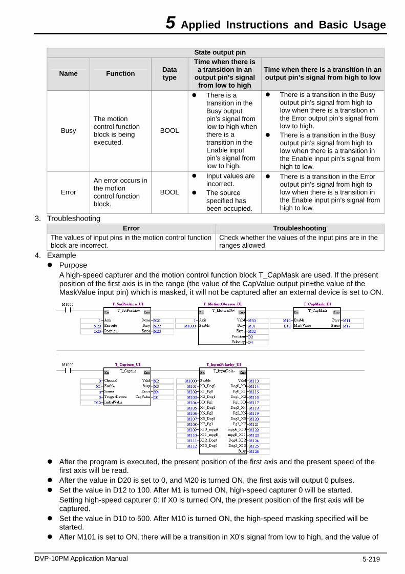
5 Applied Instructions and Basic Usage
DVP-10PM Application Manual 5-219
State output pin
Name Function Data type
Time when there is a transition in an
output pin’s signal from low to high
Time when there is a transition in an output pin’s signal from high to low
Busy control function block is being BOOL low to high when
there is a low to high.
There is a tra
The motion
executed.
There is a transition in the Busy output
There is a transition in the Busy output pin’s signal from high to
pin’s signal from
transition in the Enable input pin’s signal from low to high.
low when there is a transition in the Error output pin’s signal from
nsition in the Busy output pin’s signal from high to low when there is a transition in the Enable input pin’s signal from high to low.
Error
An error occurs in the motion control function block.
BOOL
Input values are incorrect.
The source specified has been occupied.
There is a transition in the Error output pin’s signal from high to low when there is a transition in the Enable input pin’s signal from high to low.
3. Troubleshooting Error Troubleshooting
The values of input pins in the motion control function block are incorrect.
Check whether the values of the input pins are in the ranges allowed.
4. Example Purpose
A high-speed capturer and the motion control function block T_CapMask are used. If the present position of the first axis is in the range (the value of the CapValue output pin±the value of the MaskValue input pin) which is masked, it will not be captured after an external device is set to ON.
After the program is executed, the present position of the first axis and the present speed of the
first axis will be read. After the val M20 is turned ON, the fi a 0. A s tu ed
Setting high-speed capturer 0: If X0 is turned ON, the present he first axis will be captured.
Set the value in D10 to 500. After M10 is turned ON, the high-speed masking specified will be started.
After M101 is set to ON, there will be a transition in X0’s signal from low to high, and the value of
ue in D20 is set to 0, andlue in D12 to 10
rst axis will output 0 pulses. capturer 0 will be started.
position of t Set the v fter M1 i rned ON, high-spe
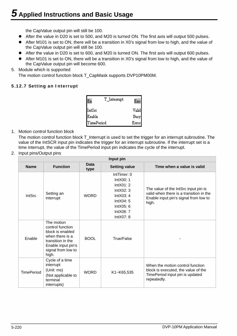
5 Applied Instructions and Basic Usage
DVP-10PM Application Manual 5-220
the CapValue output pin will still be 100. After the value in D20 is set to 500, and he first axis will output 500 pulses. 101 is set to ON, there will be a tr a
the CapValue output pin will sti 00. After the value in D20 is set to 600, a After M101 is set to ON, there will be
the CapValue output pin will become 5. Module which d
The n co lock
5.12.7 Setting rrupt
M20 is turned ON. Tansition in X0’s sign
0 ON.
After M l from low to high, and the value of ll be 1
nd M2 is turned a transition in X0’s sig600.
ask supports DVP10P
The first axis will output 600 pulses. nal from low to high, and the value of
M0 M. is supportentrol function b
an Inte
motio T_CapM 0
1. Motion control function
T value of the IntSCR input pin indicat o
pt, the value of the TimePeriod input pin indicates the cycle of the interrupt. ut pins
block he motion control function block T_Interrupt is use
es the trigger fd to set the trigger for an interrupt subroutine. Ther an interrupt subroutine. If the interrupt set is a
time interru2. Input pins/Outp
Input pin
Name Function Data type Setting value Time when a value is valid
IntSrc Setting an interrupt WORD
IntX00: 1 IntX01: 2 IntX02: 3 IntX03: 4 IntX04: 5 IntX05: 6 IntX06: 7 IntX07: 8
The value of the IntSrc input pin is valid when there is a transition in the Enable input pin’s signal from low to high.
IntTimer: 0
Enable
The motion control function block is enabled when there is a transition in the Enable input pin’s signal from low to high.
BOOL True/False -
TimePeriod (Unit: ms) (Not applicab
WORD K1~K65,535 block is executed, the value of the
Cycle of a time interrupt
le to
When the motion control function
TimePeriod input pin is updated terminal repeatedly. interrupts)
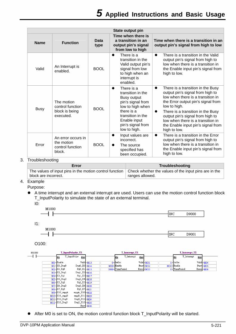
5 Applied Instructions and Basic Usage
DVP-10PM Application Manual 5-221
State output pin
Name Function Data type
Time when there is a transition in an
output pin’s signal from low to high
Time when there is a transition in an output pin’s signal from high to low
Valid An Interrupt is enabled. BOOL
Valid output pin’s signal from low
enabled.
low when there is a transition in the Enable input pin’s signal from
h to low.
There is a There is a transition in the Valid transition in the output pin’s signal from high to
to high when an interrupt is
hig
Busy
The motion control function block is being executed.
BOOL
There is a transition in the Busy output pin’s signal from low to high when there is a transition in the Enable input pin’s signal from low to high.
There is a transition in the Busy output pin’s signal from high to low when there is a transition in the Error output pin’s signal from low to high.
There is a transition in the Busy output pin’s signal from high to low when there is a transition in the Enable input pin’s signal from high to low.
Error
An error occurs in the motion control function BOOL
Input values are incorrect.
The source specified has
There is a transition in the Error output pin’s signal from high to low when there is a transition in the Enable input piblock. been occupied.
n’s signal from high to low.
3. Troubleshooting Error Troubleshooting
The values of input pins in the motion co ctioblock are incorrect.
hether the values of the input pins are in the llowed.
ntrol fun n Check wranges a
4. Example Purpose: inte n extern pt are u rs can ck
tPo imulate the I0:
A time T_Inpu
rrupt and alarity to s
al interru state of an external terminal.
sed. Use use the motion control function blo
I1:
O100:
After M0 is set to ON, the motion control function block T_InputPolarity will be started.
5 Applied Instructions and Basic Usage
DVP-10PM Application Manual 5-222
After M30 is set to ON, the time interrupt al interrupt I1 will be started. After the time interrupt I0 is started, it wil three seconds, and the value in
will inc ne eve ee se After the external interrupt I1 is d, t te
is turned from OFF to ON, the v5. Module which is supported
The motion control funct T_Interrupt su
I0 and the externl be executed every
conds. he users can simula
001 will increase
D9000 rease by o ry thr starte the state of X0 by setting M1. If M1alue in D9
pports DVP10PM
by one.
00M. ion block
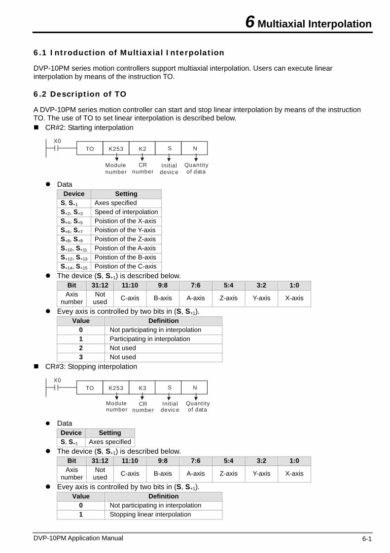
6 Multiaxial Interpolation
6.1 Introduction of Multiaxial Interpolation
DVP-10PM series motion controllers support multiaxial interpolation. Users can execute linear interpolation by means of the instruction TO.
6.2 Description of TO
A DVP-10PM series motion controller can start and stop linear interpolation by means of the instruction TO. The use of TO to set linear interpolation is described below. CR#2: Starting interpolation
X0TO K253 K2 S N
CR number
Module number
Quantity of data
Init ial device
Data Device Setting
S, S+1 Axes specified S+2, S+3 Speed of interpolation S+4, S+5 Poistion of the X-axis S+6, S+7 Poistion of the Y-axis S+8, S+9 Poistion of the Z-axis S+10, S+11 Poistion of the A-axis S+12, S+13 Poistion of the B-axis S+14, S+15 Poistion of the C-axis
The device (S, S+1) is described below. Bit 31:12 11:10 9:8 7:6 5:4 3:2 1:0 Axis
number Not
used C-axis B-axis A-axis Z-axis Y-axis X-axis
Evey axis is controlled by two bits in (S, S+1). Value Definition
0 Not participating in interpolation 1 Participating in interpolation 2 Not used 3 Not used
CR#3: Stopping interpolation
CR number
Module number
Quantity of data
Init ial device
X0TO K253 K3 S N
Data Device Setting S, S+1 Axes specified
The device (S, S+1) is described below. Bit 31:12 11:10 9:8 7:6 5:4 3:2 1:0 Axis
number Not
used C-axis B-axis A-axis Z-axis Y-axis X-axis
Evey axis is controlled by two bits in (S, S+1). Value Definition
0 Not participating in interpolation 1 Stopping linear interpolation
DVP-10PM Application Manual 6-1
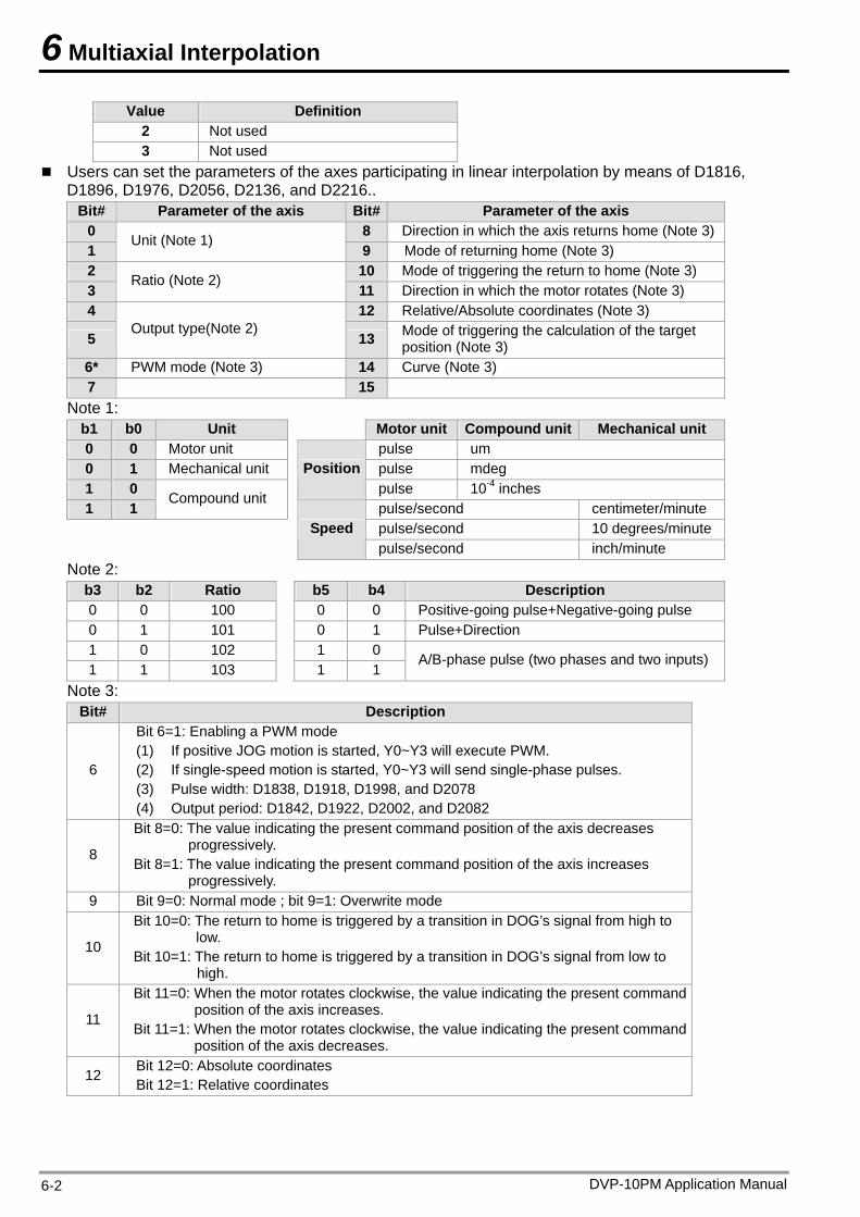
6 Multiaxial Interpolation
DVP-10PM Application Manual 6-2
Value Definition 2 Not used 3 Not used
Users can set the parameters of the axes participating in linear interpolation by means of D1816, D1896, D1976, D2056, D2136, and D2216..
Bit# Parameter of the axis Bit# Parameter of the axis 0 8 Direction in which the axis returns home (Note 3)1
Unit (Note 1) 9 Mode of returning home (Note 3)
2 10 Mode of triggering the return to home (Note 3) 3
Ratio (Note 2) 11 Direction in which the motor rotates (Note 3)
4 12 Relative/Absolute coordinates (Note 3)
5 Output type(Note 2)
13 Mode of triggering the calculation of the target position (Note 3)
6* PWM mode (Note 3) 14 Curve (Note 3) 7 15
Note 1: b1 b0 Unit Motor unit Compound unit Mechanical unit 0 0 Motor unit pulse um 0 1 Mechanical unit pulse mdeg 1 0
Positionpulse 10-4 inches
1 1 Compound unit
pulse/second centimeter/minute pulse/second 10 degrees/minute
Speed pulse/second inch/minute
Note 2: b3 b2 Ratio b5 b4 Description 0 0 100 0 0 Positive-going pulse+Negative-going pulse 0 1 101 0 1 Pulse+Direction 1 0 102 1 0 1 1 103
1 1 A/B-phase pulse (two phases and two inputs)
Note 3: Bit# Description
6
Bit 6=1: Enabling a PWM mode (1) If positive JOG motion is started, Y0~Y3 will execute PWM. (2) If single-speed motion is started, Y0~Y3 will send single-phase pulses. (3) Pulse width: D1838, D1918, D1998, and D2078 (4) Output period: D1842, D1922, D2002, and D2082
8
Bit 8=0: The value indicating the present command position of the axis decreases progressively.
Bit 8=1: The value indicating the present command position of the axis increases progressively.
9 Bit 9=0: Normal mode ; bit 9=1: Overwrite mode
10
Bit 10=0: The return to home is triggered by a transition in DOG’s signal from high to low.
Bit 10=1: The return to home is triggered by a transition in DOG’s signal from low to high.
11
Bit 11=0: When the motor rotates clockwise, the value indicating the present command position of the axis increases.
Bit 11=1: When the motor rotates clockwise, the value indicating the present command position of the axis decreases.
12 Bit 12=0: Absolute coordinates Bit 12=1: Relative coordinates
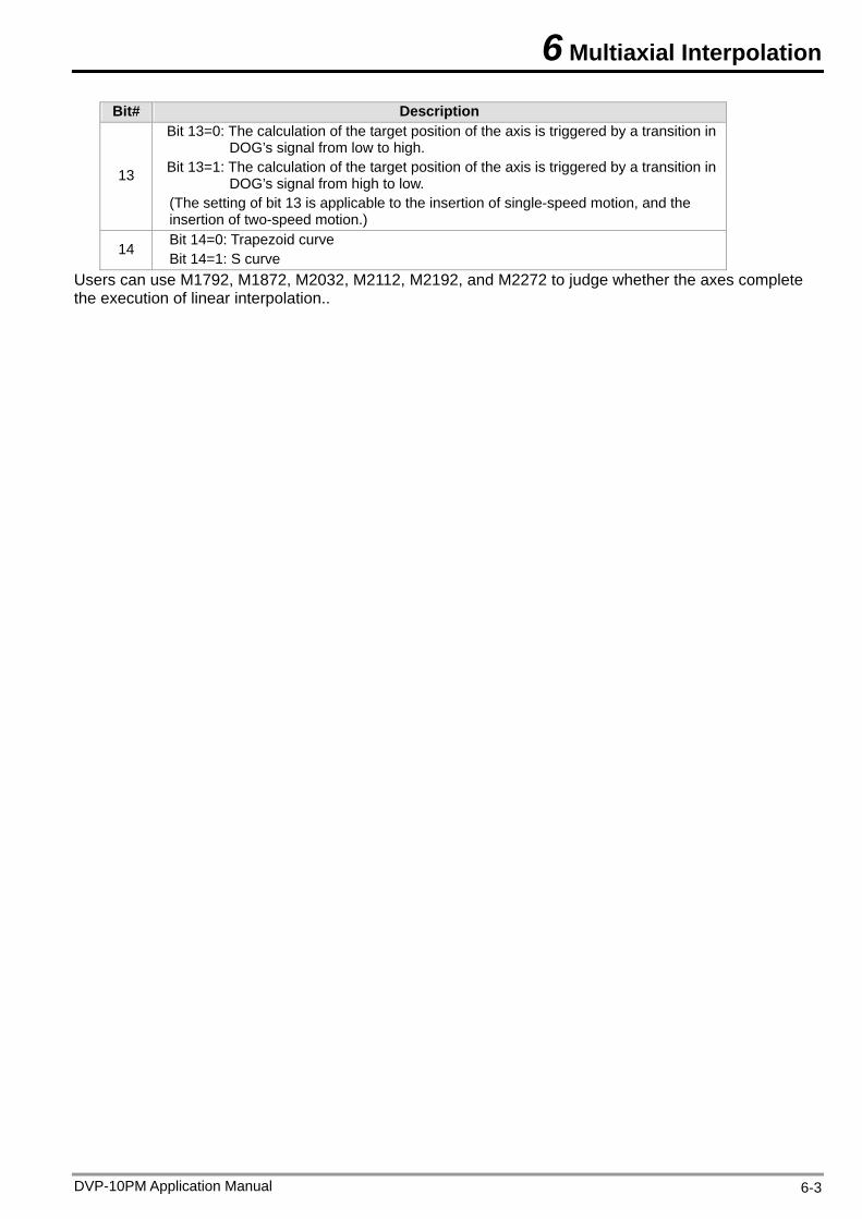
6 Multiaxial Interpolation
DVP-10PM Application Manual 6-3
Bit# Description
13
Bit 13=0: The calculation of the target position of the axis is triggered by a transition in DOG’s signal from low to high.
Bit 13=1: The calculation of the target position of the axis is triggered by a transition in DOG’s signal from high to low.
(The setting of bit 13 is applicable to the insertion of single-speed motion, and the insertion of two-speed motion.)
14 Bit 14=0: Trapezoid curve Bit 14=1: S curve
Users can use M1792, M1872, M2032, M2112, M2192, and M2272 to judge whether the axes complete the execution of linear interpolation..
6 Multiaxial Interpolation
DVP-10PM Application Manual 6-4
MEMO
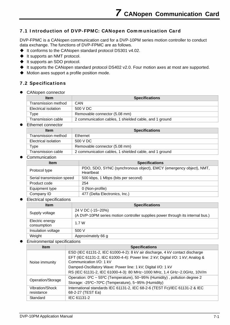
7 CANopen Communication Card
7.1 Introduction of DVP-FPMC: CANopen Communication Card
DVP-FPMC is a CANopen communication card for a DVP-10PM series motion controller to conduct data exchange. The functions of DVP-FPMC are as follows. It conforms to the CANopen standard protocol DS301 v4.02. It supports an NMT protocol. It supports an SDO protocol. It supports the CANopen standard protocol DS402 v2.0. Four motion axes at most are supported. Motion axes support a profile position mode.
7.2 Specifications
CANopen connector Item Specifications
Transmission method CAN Electrical isolation 500 V DC Type Removable connector (5.08 mm) Transmission cable 2 communication cables, 1 shielded cable, and 1 ground
Ethernet connector Item Specifications
Transmission method Ethernet Electrical isolation 500 V DC Type Removable connector (5.08 mm) Transmission cable 2 communication cables, 1 shielded cable, and 1 ground
Communication Item Specifications
Protocol type PDO, SDO, SYNC (synchronous object), EMCY (emergency object), NMT, Heartbeat
Serial transmission speed 500 kbps, 1 Mbps (bits per second) Product code 254 Equipment type 0 (Non-profile) Company ID 477 (Delta Electronics, Inc.)
Electrical specifications Item Specifications
Supply voltage 24 V DC (-15~20%) (A DVP-10PM series motion controller supplies power through its internal bus.)
Electric energy consumption 1.7 W
Insulation voltage 500 V Weight Approximately 66 g
Environmental specifications Item Specifications
Noise immunity
ESD (IEC 61131-2, IEC 61000-4-2): 8 kV air discharge, 4 kV contact discharge EFT (IEC 61131-2, IEC 61000-4-4): Power line: 2 kV; Digital I/O: 1 kV; Analog & Communication I/O: 1 kV Damped-Oscillatory Wave: Power line: 1 kV; Digital I/O: 1 kV RS (IEC 61131-2, IEC 61000-4-3): 80 MHz~1000 MHz, 1.4 GHz~2.0GHz, 10V/m
Operation/Storage Operation: 0ºC ~ 55ºC (Temperature), 50~95% (Humidity) , pollution degree 2 Storage: -25ºC~70ºC (Temperature), 5~95% (Humidity)
Vibration/Shock resistance
International standards IEC 61131-2, IEC 68-2-6 (TEST Fc)/IEC 61131-2 & IEC 68-2-27 (TEST Ea)
Standard IEC 61131-2
DVP-10PM Application Manual 7-1
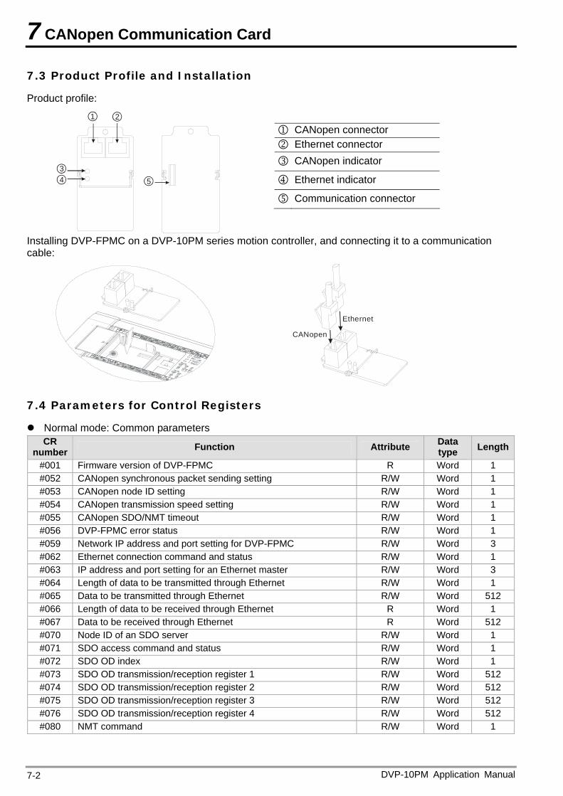
7 CANopen Communication Card
7.3 Product Profile and Installation
Product profile:
34 5
21
CANopen connector Ethernet connector
CANopen indicator
Ethernet indicator
Communication connector
Installing DVP-FPMC on a DVP-10PM series motion controller, and connecting it to a communication cable:
CANopen
Ethernet
7.4 Parameters for Control Registers
Normal mode: Common parameters CR
number Function Attribute Data type Length
#001 Firmware version of DVP-FPMC R Word 1 #052 CANopen synchronous packet sending setting R/W Word 1 #053 CANopen node ID setting R/W Word 1 #054 CANopen transmission speed setting R/W Word 1 #055 CANopen SDO/NMT timeout R/W Word 1 #056 DVP-FPMC error status R/W Word 1 #059 Network IP address and port setting for DVP-FPMC R/W Word 3 #062 Ethernet connection command and status R/W Word 1 #063 IP address and port setting for an Ethernet master R/W Word 3 #064 Length of data to be transmitted through Ethernet R/W Word 1 #065 Data to be transmitted through Ethernet R/W Word 512 #066 Length of data to be received through Ethernet R Word 1 #067 Data to be received through Ethernet R Word 512 #070 Node ID of an SDO server R/W Word 1 #071 SDO access command and status R/W Word 1 #072 SDO OD index R/W Word 1 #073 SDO OD transmission/reception register 1 R/W Word 512 #074 SDO OD transmission/reception register 2 R/W Word 512 #075 SDO OD transmission/reception register 3 R/W Word 512 #076 SDO OD transmission/reception register 4 R/W Word 512 #080 NMT command R/W Word 1
DVP-10PM Application Manual 7-2
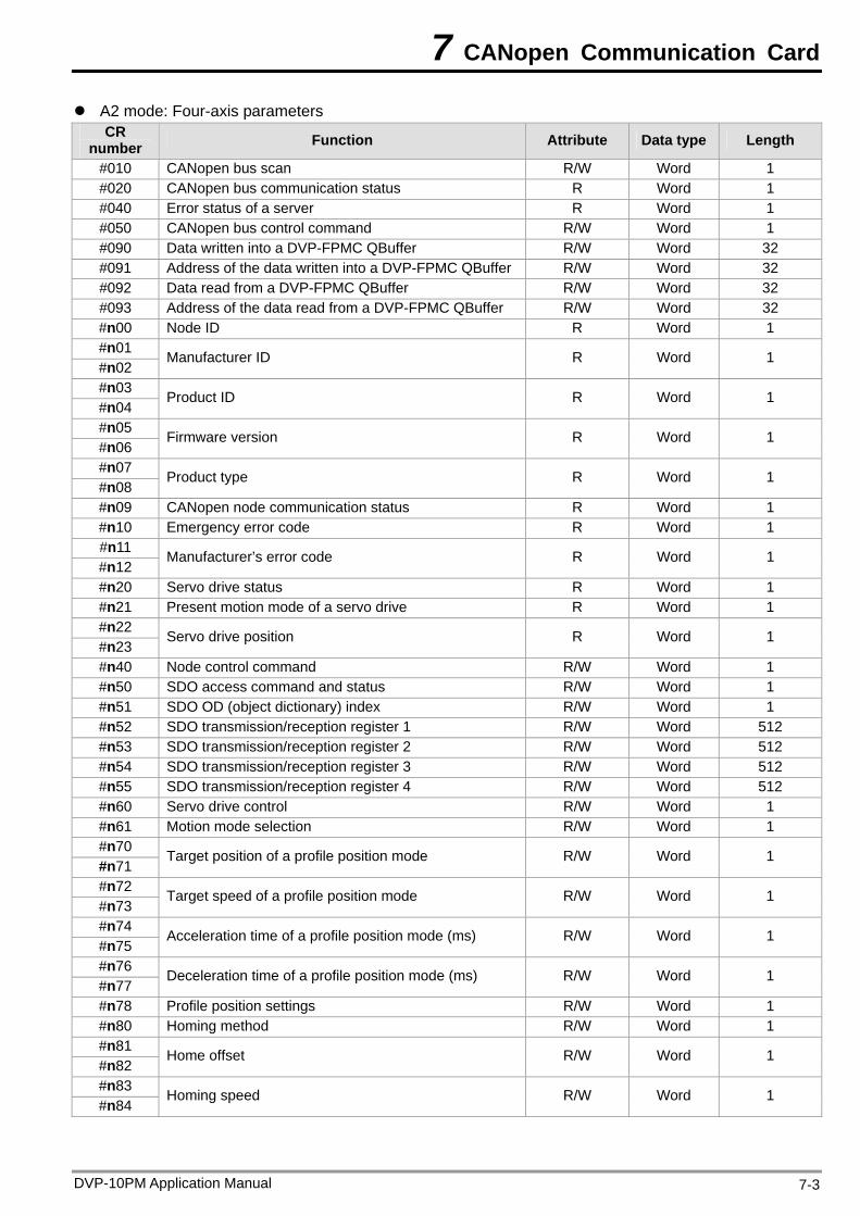
7 CANopen Communication Card
A2 mode: Four-axis parameters CR
number Function Attribute Data type Length
#010 CANopen bus scan R/W Word 1 #020 CANopen bus communication status R Word 1 #040 Error status of a server R Word 1 #050 CANopen bus control command R/W Word 1 #090 Data written into a DVP-FPMC QBuffer R/W Word 32 #091 Address of the data written into a DVP-FPMC QBuffer R/W Word 32 #092 Data read from a DVP-FPMC QBuffer R/W Word 32 #093 Address of the data read from a DVP-FPMC QBuffer R/W Word 32 #n00 Node ID R Word 1 #n01 #n02
Manufacturer ID R Word 1
#n03 #n04
Product ID R Word 1
#n05 #n06
Firmware version R Word 1
#n07 #n08
Product type R Word 1
#n09 CANopen node communication status R Word 1 #n10 Emergency error code R Word 1 #n11 #n12
Manufacturer’s error code R Word 1
#n20 Servo drive status R Word 1 #n21 Present motion mode of a servo drive R Word 1 #n22 #n23
Servo drive position R Word 1
#n40 Node control command R/W Word 1 #n50 SDO access command and status R/W Word 1 #n51 SDO OD (object dictionary) index R/W Word 1 #n52 SDO transmission/reception register 1 R/W Word 512 #n53 SDO transmission/reception register 2 R/W Word 512 #n54 SDO transmission/reception register 3 R/W Word 512 #n55 SDO transmission/reception register 4 R/W Word 512 #n60 Servo drive control R/W Word 1 #n61 Motion mode selection R/W Word 1 #n70 #n71
Target position of a profile position mode R/W Word 1
#n72 #n73
Target speed of a profile position mode R/W Word 1
#n74 #n75
Acceleration time of a profile position mode (ms) R/W Word 1
#n76 #n77
Deceleration time of a profile position mode (ms) R/W Word 1
#n78 Profile position settings R/W Word 1 #n80 Homing method R/W Word 1 #n81 #n82
Home offset R/W Word 1
#n83 #n84
Homing speed R/W Word 1
DVP-10PM Application Manual 7-3
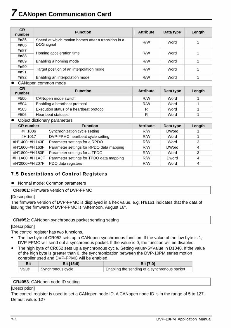
7 CANopen Communication Card
DVP-10PM Application Manual 7-4
CR number Function Attribute Data type Length
#n85 #n86
Speed at which motion homes after a transition in a DOG signal R/W Word 1
#n87 #n88
Homing acceleration time R/W Word 1
#n89 Enabling a homing mode R/W Word 1 #n90 #n91
Target position of an interpolation mode R/W Word 1
#n92 Enabling an interpolation mode R/W Word 1 CANopen common mode
CR number Function Attribute Data type Length
#500 CANopen mode switch R/W Word 1 #504 Enabling a heartbeat protocol R/W Word 1 #505 Execution status of a heartbeat protocol R Word 1 #506 Heartbeat statuses R Word 1
Object dictionary parameters CR number Function Attribute Data type Length
#H’1006 Synchronization cycle setting R/W DWord 1 #H’1017 DVP-FPMC heartbeat cycle setting R/W Word 1
#H’1400~#H’143F Parameter settings for a RPDO R/W Word 3 #H’1600~#H’163F Parameter settings for RPDO data mapping R/W DWord 4 #H’1800~#H’183F Parameter settings for a TPDO R/W Word 3 #H’1A00~#H’1A3F Parameter settings for TPDO data mapping R/W Dword 4 #H’2000~#H’207F PDO data registers R/W Word 4
7.5 Descriptions of Control Registers
Normal mode: Common parameters CR#001: Firmware version of DVP-FPMC
[Description] The firmware version of DVP-FPMC is displayed in a hex value, e.g. H’8161 indicates that the data of issuing the firmware of DVP-FPMC is “Afternoon, August 16”. CR#052: CANopen synchronous packet sending setting
[Description] The control register has two functions. The low byte of CR052 sets up a CANopen synchronous function. If the value of the low byte is 1,
DVP-FPMC will send out a synchronous packet. If the value is 0, the function will be disabled. The high byte of CR052 sets up a synchronous cycle. Setting value×5=Value in D1040. If the value
of the high byte is greater than 0, the synchronization between the DVP-10PM series motion controller used and DVP-FPMC will be enabled.
Bit Bit [15:8] Bit [7:0] Value Synchronous cycle Enabling the sending of a synchronous packet
CR#053: CANopen node ID setting
[Description] The control register is used to set a CANopen node ID. A CANopen node ID is in the range of 5 to 127. Default value: 127
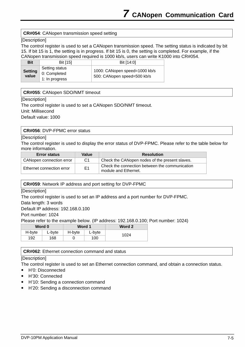
7 CANopen Communication Card
CR#054: CANopen transmission speed setting [Description] The control register is used to set a CANopen transmission speed. The setting status is indicated by bit 15. If bit 15 is 1, the setting is in progress. If bit 15 is 0, the setting is completed. For example, if the CANopen transmission speed required is 1000 kb/s, users can write K1000 into CR#054.
Bit Bit [15] Bit [14:0]
Setting value
Setting status 0: Completed 1: In progress
1000: CANopen speed=1000 kb/s 500: CANopen speed=500 kb/s
CR#055: CANopen SDO/NMT timeout
[Description] The control register is used to set a CANopen SDO/NMT timeout. Unit: Millisecond Default value: 1000 CR#056: DVP-FPMC error status
[Description] The control register is used to display the error status of DVP-FPMC. Please refer to the table below for more information.
Error status Value Resolution CANopen connection error C1 Check the CANopen nodes of the present slaves.
Ethernet connection error E1 Check the connection between the communication module and Ethernet.
CR#059: Network IP address and port setting for DVP-FPMC
[Description] The control register is used to set an IP address and a port number for DVP-FPMC. Data length: 3 words Default IP address: 192.168.0.100 Port number: 1024 Please refer to the example below. (IP address: 192.168.0.100; Port number: 1024)
Word 0 Word 1 Word 2 H-byte L-byte H-byte L-byte
192 168 0 100 1024
CR#062: Ethernet connection command and status
[Description] The control register is used to set an Ethernet connection command, and obtain a connection status. H’0: Disconnected H’30: Connected H’10: Sending a connection command H’20: Sending a disconnection command
DVP-10PM Application Manual 7-5
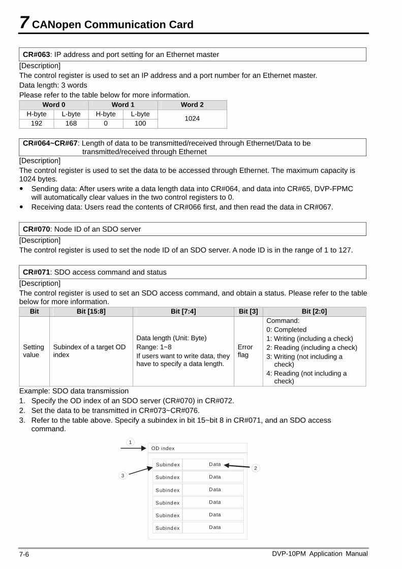
7 CANopen Communication Card
CR#063: IP address and port setting for an Ethernet master [Description] The control register is used to set an IP address and a port number for an Ethernet master. Data length: 3 words Please refer to the table below for more information.
Word 0 Word 1 Word 2 H-byte L-byte H-byte L-byte
192 168 0 100 1024
CR#064~CR#67: Length of data to be transmitted/received through Ethernet/Data to be
transmitted/received through Ethernet [Description] The control register is used to set the data to be accessed through Ethernet. The maximum capacity is 1024 bytes. Sending data: After users write a data length data into CR#064, and data into CR#65, DVP-FPMC
will automatically clear values in the two control registers to 0. Receiving data: Users read the contents of CR#066 first, and then read the data in CR#067. CR#070: Node ID of an SDO server
[Description] The control register is used to set the node ID of an SDO server. A node ID is in the range of 1 to 127. CR#071: SDO access command and status
[Description] The control register is used to set an SDO access command, and obtain a status. Please refer to the table below for more information.
Bit Bit [15:8] Bit [7:4] Bit [3] Bit [2:0]
Setting value
Subindex of a target OD index
Data length (Unit: Byte) Range: 1~8 If users want to write data, they have to specify a data length.
Error flag
Command: 0: Completed 1: Writing (including a check) 2: Reading (including a check) 3: Writing (not including a
check) 4: Reading (not including a
check) Example: SDO data transmission 1. Specify the OD index of an SDO server (CR#070) in CR#072. 2. Set the data to be transmitted in CR#073~CR#076. 3. Refer to the table above. Specify a subindex in bit 15~bit 8 in CR#071, and an SDO access
command.
OD index
Subind ex Data
Data
Data
Data
Data
Data
1
32
Subindex
Subindex
Subindex
Subindex
Subindex
DVP-10PM Application Manual 7-6
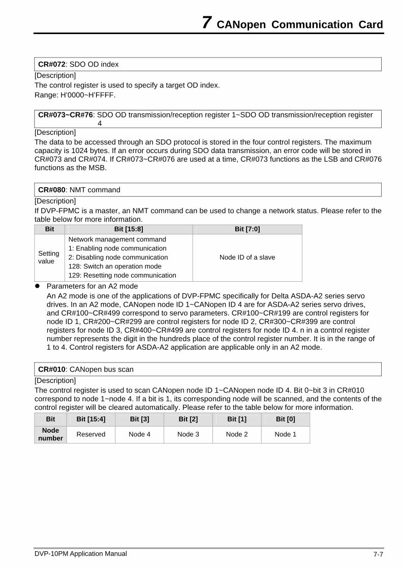
7 CANopen Communication Card
CR#072: SDO OD index
[Description] The control register is used to specify a target OD index. Range: H’0000~H’FFFF. CR#073~CR#76: SDO OD transmission/reception register 1~SDO OD transmission/reception register
4 [Description] The data to be accessed through an SDO protocol is stored in the four control registers. The maximum capacity is 1024 bytes. If an error occurs during SDO data transmission, an error code will be stored in CR#073 and CR#074. If CR#073~CR#076 are used at a time, CR#073 functions as the LSB and CR#076 functions as the MSB. CR#080: NMT command
[Description] If DVP-FPMC is a master, an NMT command can be used to change a network status. Please refer to the table below for more information.
Bit Bit [15:8] Bit [7:0]
Setting value
Network management command 1: Enabling node communication 2: Disabling node communication 128: Switch an operation mode 129: Resetting node communication
Node ID of a slave
Parameters for an A2 mode An A2 mode is one of the applications of DVP-FPMC specifically for Delta ASDA-A2 series servo drives. In an A2 mode, CANopen node ID 1~CANopen ID 4 are for ASDA-A2 series servo drives, and CR#100~CR#499 correspond to servo parameters. CR#100~CR#199 are control registers for node ID 1, CR#200~CR#299 are control registers for node ID 2, CR#300~CR#399 are control registers for node ID 3, CR#400~CR#499 are control registers for node ID 4. n in a control register number represents the digit in the hundreds place of the control register number. It is in the range of 1 to 4. Control registers for ASDA-A2 application are applicable only in an A2 mode.
CR#010: CANopen bus scan
[Description] The control register is used to scan CANopen node ID 1~CANopen node ID 4. Bit 0~bit 3 in CR#010 correspond to node 1~node 4. If a bit is 1, its corresponding node will be scanned, and the contents of the control register will be cleared automatically. Please refer to the table below for more information.
Bit Bit [15:4] Bit [3] Bit [2] Bit [1] Bit [0] Node
number Reserved Node 4 Node 3 Node 2 Node 1
DVP-10PM Application Manual 7-7
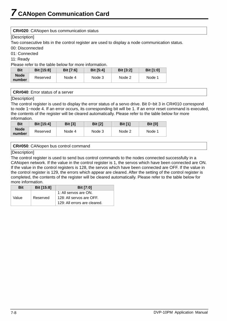
7 CANopen Communication Card
CR#020: CANopen bus communication status [Description] Two consecutive bits in the control register are used to display a node communication status. 00: Disconnected 01: Connected 11: Ready Please refer to the table below for more information.
Bit Bit [15:8] Bit [7:6] Bit [5:4] Bit [3:2] Bit [1:0] Node
number Reserved Node 4 Node 3 Node 2 Node 1
CR#040: Error status of a server
[Description] The control register is used to display the error status of a servo drive. Bit 0~bit 3 in CR#010 correspond to node 1~node 4. If an error occurs, its corresponding bit will be 1. If an error reset command is executed, the contents of the register will be cleared automatically. Please refer to the table below for more information.
Bit Bit [15:4] Bit [3] Bit [2] Bit [1] Bit [0] Node
number Reserved Node 4 Node 3 Node 2 Node 1
CR#050: CANopen bus control command
[Description] The control register is used to send bus control commands to the nodes connected successfully in a CANopen network. If the value in the control register is 1, the servos which have been connected are ON. If the value in the control registers is 128, the servos which have been connected are OFF. If the value in the control register is 129, the errors which appear are cleared. After the setting of the control register is completed, the contents of the register will be cleared automatically. Please refer to the table below for more information.
Bit Bit [15:8] Bit [7:0]
Value Reserved 1: All servos are ON. 128: All servos are OFF. 129: All errors are cleared.
DVP-10PM Application Manual 7-8
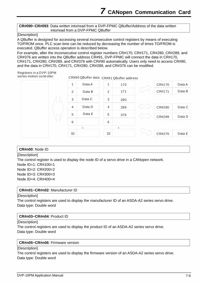
7 CANopen Communication Card
CR#090~CR#093: Data written into/read from a DVP-FPMC QBuffer/Address of the data written into/read from a DVP-FPMC QBuffer
[Description] A QBuffer is designed for accessing several inconsecutive control registers by means of executing TO/FROM once. PLC scan time can be reduced by decreasing the number of times TO/FROM is executed. QBuffer access operation is described below. For example, after the inconsecutive control register numbers CR#170, CR#171, CR#280, CR#289, and CR#376 are written into the QBuffer address CR#91, DVP-FPMC will connect the data in CR#170, CR#171, CR#280, CR#289, and CR#376 with CR#90 automatically. Users only need to access CR#90, and the data in CR#170, CR#171, CR#280, CR#289, and CR#376 can be modified.
Data A
CR#90 dataQ ufferB CR#91 QBuffer address
CR#170
CR#280
CR#289
CR#376
CR#171 Data B
Data C
Data D
Data E
1
2
3
4
5
6
32
1
2
3
4
5
6
32
170
171
280
289
376
Data A
Data B
Data C
Data D
Data E
Registers in a DVP-10PM series motion controller
CR#n00: Node ID
[Description] The control register is used to display the node ID of a servo drive in a CANopen network. Node ID=1: CR#100=1 Node ID=2: CR#200=2 Node ID=3: CR#300=3 Node ID=4: CR#400=4 CR#n01~CR#n02: Manufacturer ID
[Description] The control registers are used to display the manufacturer ID of an ASDA-A2 series servo drive. Data type: Double word CR#n03~CR#n04: Product ID
[Description] The control registers are used to display the product ID of an ASDA-A2 series servo drive. Data type: Double word CR#n05~CR#n06: Firmware version
[Description] The control registers are used to display the firmware version of an ASDA-A2 series servo drive. Data type: Double word
DVP-10PM Application Manual 7-9
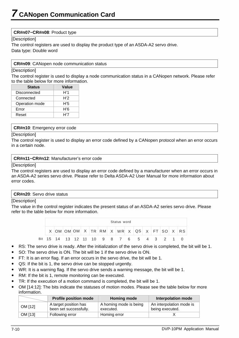
7 CANopen Communication Card
CR#n07~CR#n08: Product type [Description] The control registers are used to display the product type of an ASDA-A2 servo drive. Data type: Double word CR#n09: CANopen node communication status
[Description] The control register is used to display a node communication status in a CANopen network. Please refer to the table below for more information.
Status Value Disconnected H’1 Connected H’2 Operation mode H’5 Error H’6 Reset H’7
CR#n10: Emergency error code
[Description] The control register is used to display an error code defined by a CANopen protocol when an error occurs in a certain node. CR#n11~CR#n12: Manufacturer’s error code
[Description] The control registers are used to display an error code defined by a manufacturer when an error occurs in an ASDA-A2 series servo drive. Please refer to Delta ASDA-A2 User Manual for more information about error codes. CR#n20: Servo drive status
[Description] The value in the control register indicates the present status of an ASDA-A2 series servo drive. Please refer to the table below for more information.
RSXSOFT
0123456789101112131415
QSWR XXTROMOM XX
Status word
Bit
XRMOM
RS: The servo drive is ready. After the initialization of the servo drive is completed, the bit will be 1. SO: The servo drive is ON. The bit will be 1 if the servo drive is ON. FT: It is an error flag. If an error occurs in the servo drive, the bit will be 1. QS: If the bit is 1, the servo drive can be stopped urgently. WR: It is a warning flag. If the servo drive sends a warning message, the bit will be 1. RM: If the bit is 1, remote monitoring can be executed. TR: If the execution of a motion command is completed, the bit will be 1. OM [14:12]: The bits indicate the statuses of motion modes. Please see the table below for more
information. Profile position mode Homing mode Interpolation mode
OM [12] A target position has been set successfully.
A homing mode is being executed.
An interpolation mode is being executed.
OM [13] Following error Homing error X
DVP-10PM Application Manual 7-10
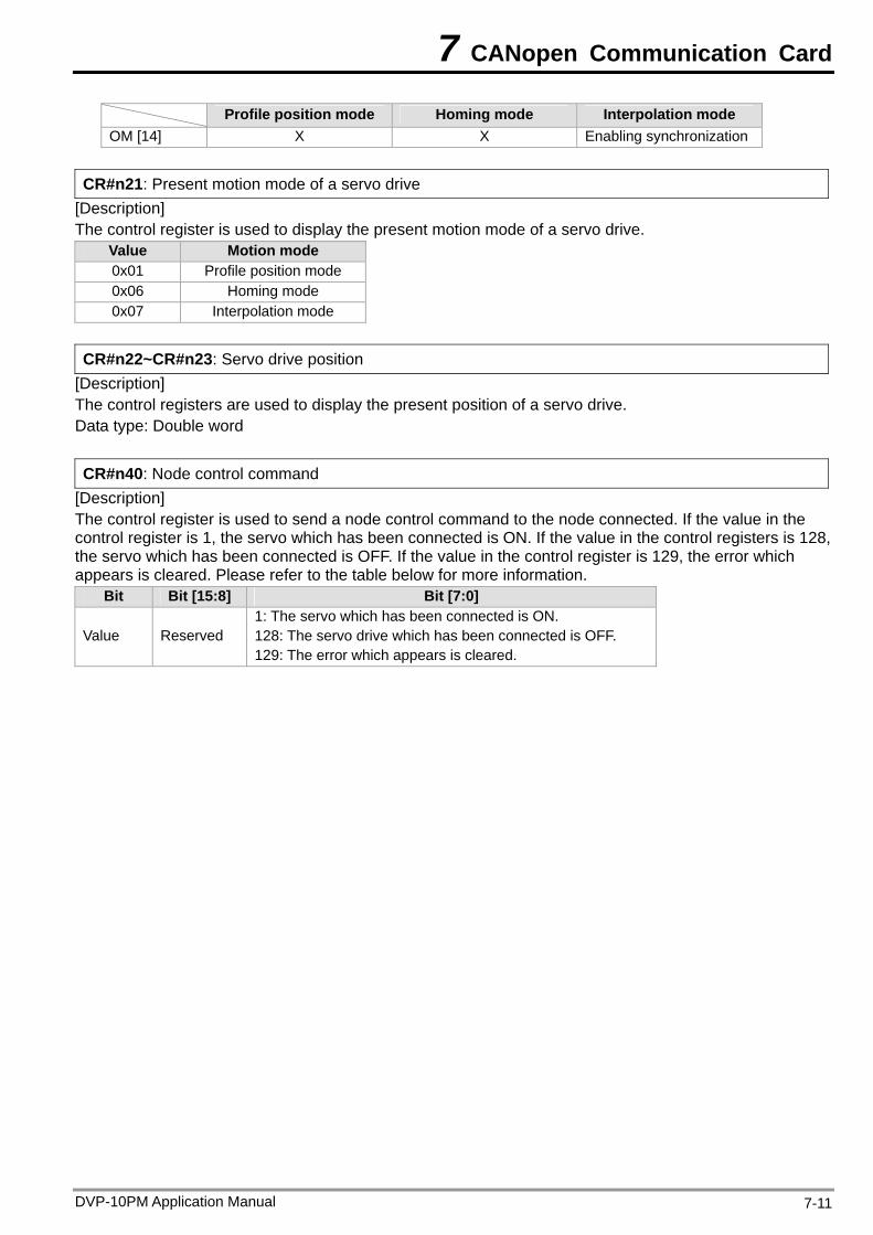
7 CANopen Communication Card
DVP-10PM Application Manual 7-11
Profile position mode Homing mode Interpolation mode OM [14] X X Enabling synchronization
CR#n21: Present motion mode of a servo drive
[Description] The control register is used to display the present motion mode of a servo drive.
Value Motion mode 0x01 Profile position mode 0x06 Homing mode 0x07 Interpolation mode
CR#n22~CR#n23: Servo drive position
[Description] The control registers are used to display the present position of a servo drive. Data type: Double word CR#n40: Node control command
[Description] The control register is used to send a node control command to the node connected. If the value in the control register is 1, the servo which has been connected is ON. If the value in the control registers is 128, the servo which has been connected is OFF. If the value in the control register is 129, the error which appears is cleared. Please refer to the table below for more information.
Bit Bit [15:8] Bit [7:0]
Value Reserved 1: The servo which has been connected is ON. 128: The servo drive which has been connected is OFF. 129: The error which appears is cleared.
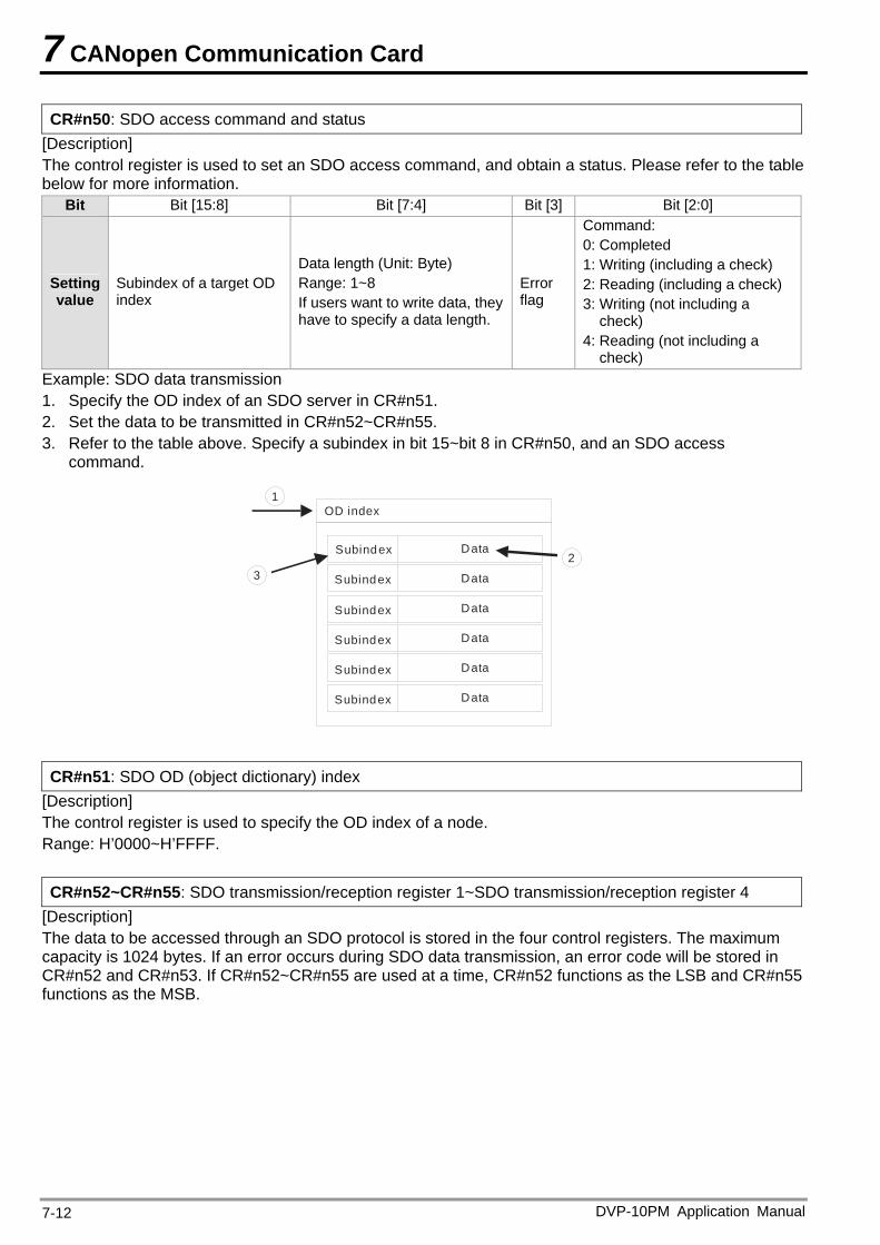
7 CANopen Communication Card
CR#n50: SDO access command and status [Description] The control register is used to set an SDO access command, and obtain a status. Please refer to the table below for more information.
Bit Bit [15:8] Bit [7:4] Bit [3] Bit [2:0]
Setting value
Subindex of a target OD index
Data length (Unit: Byte) Range: 1~8 If users want to write data, they have to specify a data length.
Error flag
Command: 0: Completed 1: Writing (including a check) 2: Reading (including a check) 3: Writing (not including a
check) 4: Reading (not including a
check) Example: SDO data transmission 1. Specify the OD index of an SDO server in CR#n51. 2. Set the data to be transmitted in CR#n52~CR#n55. 3. Refer to the table above. Specify a subindex in bit 15~bit 8 in CR#n50, and an SDO access
command.
OD index
Subindex Data
Data
Data
Data
Data
Data
1
32
Subindex
Subindex
Subindex
Subindex
Subindex
CR#n51: SDO OD (object dictionary) index
[Description] The control register is used to specify the OD index of a node. Range: H’0000~H’FFFF. CR#n52~CR#n55: SDO transmission/reception register 1~SDO transmission/reception register 4
[Description] The data to be accessed through an SDO protocol is stored in the four control registers. The maximum capacity is 1024 bytes. If an error occurs during SDO data transmission, an error code will be stored in CR#n52 and CR#n53. If CR#n52~CR#n55 are used at a time, CR#n52 functions as the LSB and CR#n55 functions as the MSB.
DVP-10PM Application Manual 7-12
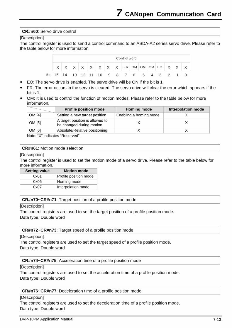
7 CANopen Communication Card
CR#n60: Servo drive control [Description] The control register is used to send a control command to an ASDA-A2 series servo drive. Please refer to the table below for more information.
XXXEO
0123456789101112131415
OMOMOMFRXXXXXXXX
Control word
Bit EO: The servo drive is enabled. The servo drive will be ON if the bit is 1. FR: The error occurs in the servo is cleared. The servo drive will clear the error which appears if the
bit is 1. OM: It is used to control the function of motion modes. Please refer to the table below for more
information. Profile position mode Homing mode Interpolation mode OM [4] Setting a new target position Enabling a homing mode X
OM [5] A target position is allowed to be changed during motion. X X
OM [6] Absolute/Relative positioning X X Note: “X” indicates “Reserved”.
CR#n61: Motion mode selection
[Description] The control register is used to set the motion mode of a servo drive. Please refer to the table below for more information.
Setting value Motion mode 0x01 Profile position mode 0x06 Homing mode 0x07 Interpolation mode
CR#n70~CR#n71: Target position of a profile position mode
[Description] The control registers are used to set the target position of a profile position mode. Data type: Double word CR#n72~CR#n73: Target speed of a profile position mode
[Description] The control registers are used to set the target speed of a profile position mode. Data type: Double word CR#n74~CR#n75: Acceleration time of a profile position mode
[Description] The control registers are used to set the acceleration time of a profile position mode. Data type: Double word CR#n76~CR#n77: Deceleration time of a profile position mode
[Description] The control registers are used to set the deceleration time of a profile position mode. Data type: Double word
DVP-10PM Application Manual 7-13
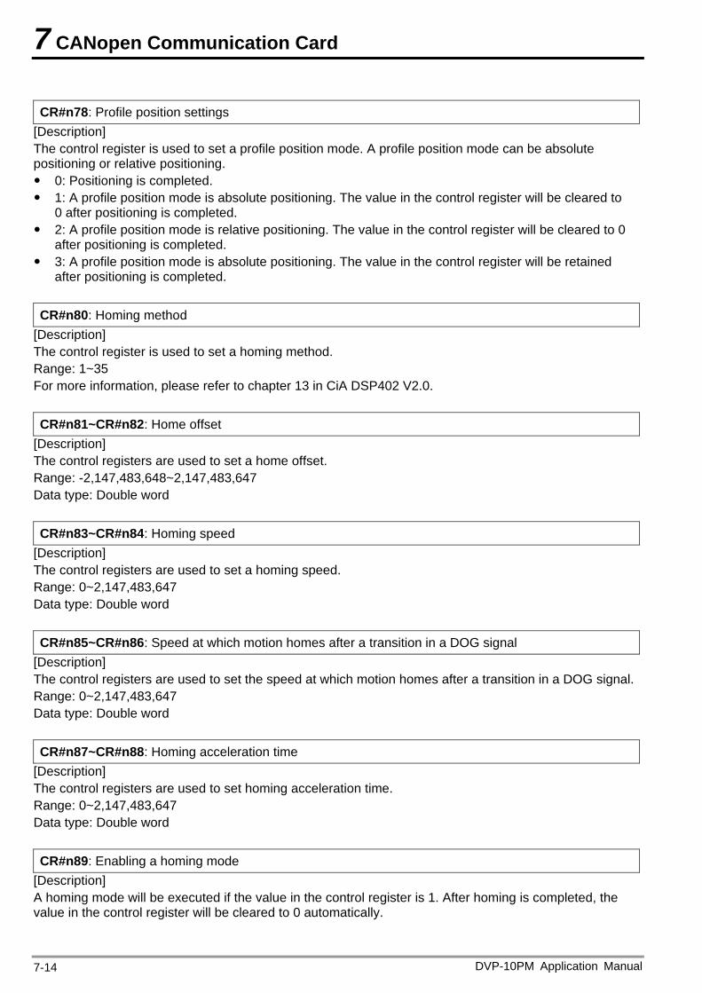
7 CANopen Communication Card
CR#n78: Profile position settings
[Description] The control register is used to set a profile position mode. A profile position mode can be absolute positioning or relative positioning. 0: Positioning is completed. 1: A profile position mode is absolute positioning. The value in the control register will be cleared to
0 after positioning is completed. 2: A profile position mode is relative positioning. The value in the control register will be cleared to 0
after positioning is completed. 3: A profile position mode is absolute positioning. The value in the control register will be retained
after positioning is completed. CR#n80: Homing method
[Description] The control register is used to set a homing method. Range: 1~35 For more information, please refer to chapter 13 in CiA DSP402 V2.0. CR#n81~CR#n82: Home offset
[Description] The control registers are used to set a home offset. Range: -2,147,483,648~2,147,483,647 Data type: Double word CR#n83~CR#n84: Homing speed
[Description] The control registers are used to set a homing speed. Range: 0~2,147,483,647 Data type: Double word CR#n85~CR#n86: Speed at which motion homes after a transition in a DOG signal
[Description] The control registers are used to set the speed at which motion homes after a transition in a DOG signal. Range: 0~2,147,483,647 Data type: Double word CR#n87~CR#n88: Homing acceleration time
[Description] The control registers are used to set homing acceleration time. Range: 0~2,147,483,647 Data type: Double word CR#n89: Enabling a homing mode
[Description] A homing mode will be executed if the value in the control register is 1. After homing is completed, the value in the control register will be cleared to 0 automatically.
DVP-10PM Application Manual 7-14
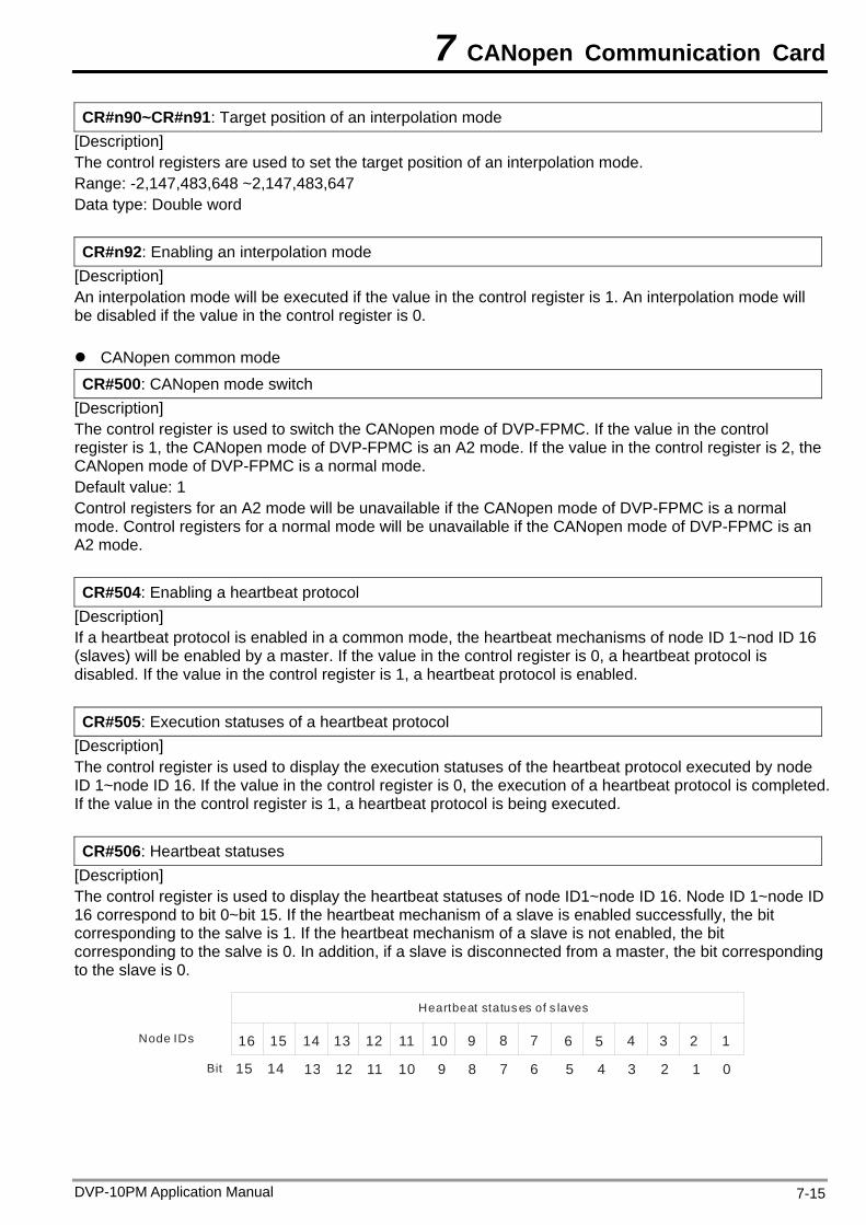
7 CANopen Communication Card
CR#n90~CR#n91: Target position of an interpolation mode [Description] The control registers are used to set the target position of an interpolation mode. Range: -2,147,483,648 ~2,147,483,647 Data type: Double word CR#n92: Enabling an interpolation mode
[Description] An interpolation mode will be executed if the value in the control register is 1. An interpolation mode will be disabled if the value in the control register is 0. CANopen common mode CR#500: CANopen mode switch
[Description] The control register is used to switch the CANopen mode of DVP-FPMC. If the value in the control register is 1, the CANopen mode of DVP-FPMC is an A2 mode. If the value in the control register is 2, the CANopen mode of DVP-FPMC is a normal mode. Default value: 1 Control registers for an A2 mode will be unavailable if the CANopen mode of DVP-FPMC is a normal mode. Control registers for a normal mode will be unavailable if the CANopen mode of DVP-FPMC is an A2 mode. CR#504: Enabling a heartbeat protocol
[Description] If a heartbeat protocol is enabled in a common mode, the heartbeat mechanisms of node ID 1~nod ID 16 (slaves) will be enabled by a master. If the value in the control register is 0, a heartbeat protocol is disabled. If the value in the control register is 1, a heartbeat protocol is enabled. CR#505: Execution statuses of a heartbeat protocol
[Description] The control register is used to display the execution statuses of the heartbeat protocol executed by node ID 1~node ID 16. If the value in the control register is 0, the execution of a heartbeat protocol is completed. If the value in the control register is 1, a heartbeat protocol is being executed. CR#506: Heartbeat statuses
[Description] The control register is used to display the heartbeat statuses of node ID1~node ID 16. Node ID 1~node ID 16 correspond to bit 0~bit 15. If the heartbeat mechanism of a slave is enabled successfully, the bit corresponding to the salve is 1. If the heartbeat mechanism of a slave is not enabled, the bit corresponding to the salve is 0. In addition, if a slave is disconnected from a master, the bit corresponding to the slave is 0.
1234
0123456789101112131415
5678910111213141516
Bit
Heartbeat statuses of s laves
Node IDs
DVP-10PM Application Manual 7-15
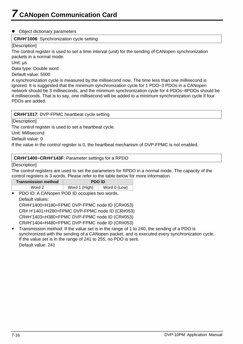
7 CANopen Communication Card
Object dictionary parameters CR#H’1006: Synchronization cycle setting
[Description] The control register is used to set a time interval (unit) for the sending of CANopen synchronization packets in a normal mode. Unit: μs Data type: Double word Default value: 5000 A synchronization cycle is measured by the millisecond now. The time less than one millisecond is ignored. It is suggested that the minimum synchronization cycle for 1 PDO~3 PDOs in a CANopen network should be 3 milliseconds, and the minimum synchronization cycle for 4 PDOs~8PDOs should be 4 milliseconds. That is to say, one millisecond will be added to a minimum synchronization cycle if four PDOs are added. CR#H’1017: DVP-FPMC heartbeat cycle setting
[Description] The control register is used to set a heartbeat cycle. Unit: Millisecond Default value: 0 If the value in the control register is 0, the heartbeat mechanism of DVP-FPMC is not enabled. CR#H’1400~CR#H’143F: Parameter settings for a RPDO
[Description] The control registers are used to set the parameters for RPDO in a normal mode. The capacity of the control registers is 3 words. Please refer to the table below for more information.
Transmission method PDO ID Word 2 Word 1 (High) Word 0 (Low)
PDO ID: A CANopen POD ID occupies two words. Default values: CR#H’1400=H180+FPMC DVP-FPMC node ID (CR#053) CR# H’1401=H280+FPMC DVP-FPMC node ID (CR#053) CR#H’1403=H380+FPMC DVP-FPMC node ID (CR#053) CR#H’1404=H480+FPMC DVP-FPMC node ID (CR#053)
Transmission method: If the value set is in the range of 1 to 240, the sending of a PDO is synchronized with the sending of a CANopen packet, and is executed every synchronization cycle. If the value set is in the range of 241 to 255, no PDO is sent. Default value: 241
DVP-10PM Application Manual 7-16
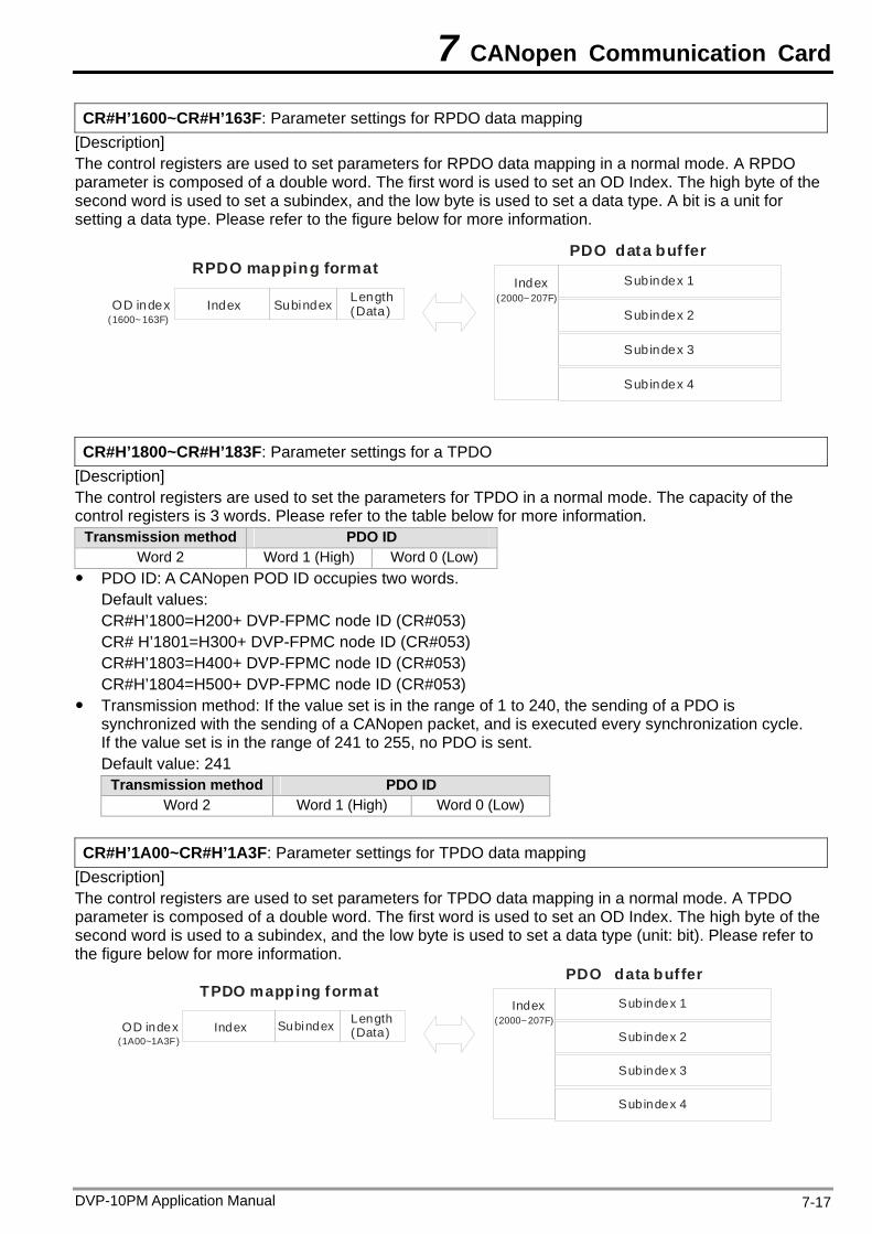
7 CANopen Communication Card
CR#H’1600~CR#H’163F: Parameter settings for RPDO data mapping [Description] The control registers are used to set parameters for RPDO data mapping in a normal mode. A RPDO parameter is composed of a double word. The first word is used to set an OD Index. The high byte of the second word is used to set a subindex, and the low byte is used to set a data type. A bit is a unit for setting a data type. Please refer to the figure below for more information.
RPDO mapping formatPDO data buf fer
SubindexOD index
Subindex 1 IndexLength(Data) Subindex 2
Subindex 3
Subindex 4
Index(1600~163F)
(2000~207F)
CR#H’1800~CR#H’183F: Parameter settings for a TPDO
[Description] The control registers are used to set the parameters for TPDO in a normal mode. The capacity of the control registers is 3 words. Please refer to the table below for more information.
Transmission method PDO ID Word 2 Word 1 (High) Word 0 (Low)
PDO ID: A CANopen POD ID occupies two words. Default values: CR#H’1800=H200+ DVP-FPMC node ID (CR#053) CR# H’1801=H300+ DVP-FPMC node ID (CR#053) CR#H’1803=H400+ DVP-FPMC node ID (CR#053) CR#H’1804=H500+ DVP-FPMC node ID (CR#053)
Transmission method: If the value set is in the range of 1 to 240, the sending of a PDO is synchronized with the sending of a CANopen packet, and is executed every synchronization cycle. If the value set is in the range of 241 to 255, no PDO is sent. Default value: 241
Transmission method PDO ID Word 2 Word 1 (High) Word 0 (Low)
CR#H’1A00~CR#H’1A3F: Parameter settings for TPDO data mapping
[Description] The control registers are used to set parameters for TPDO data mapping in a normal mode. A TPDO parameter is composed of a double word. The first word is used to set an OD Index. The high byte of the second word is used to a subindex, and the low byte is used to set a data type (unit: bit). Please refer to the figure below for more information.
TPDO mapping formatPDO data buf fer
SubindexOD index
Subindex 1 IndexLength(Data) Subindex 2
Subindex 3
Subindex 4
Index(1A00~1A3F)
(2000~207F)
DVP-10PM Application Manual 7-17
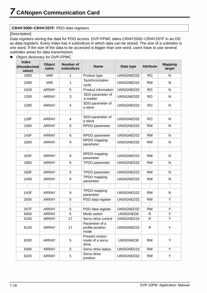
7 CANopen Communication Card
CR#H’2000~CR#H’207F: PDO data registers [Description] Data registers storing the data for PDO access. DVP-FPMC takes CR#H’2000~CR#H’207F in an OD as data registers. Every index has 4 subindices in which data can be stored. The size of a subindex is one word. If the size of the data to be accessed is bigger than one word, users have to use several subindex areas for data transmission. Object dictionary for DVP-FPMC
Index (Hexadecimal
value)
Object name
Number of subindices Name Data type Attribute Mapping
target
1000 VAR 1 Product type UNSIGNED32 RO N
1006 VAR 1 Synchronization cycle UNSIGNED32 RW N
1018 ARRAY 5 Product information UNSIGNED32 RO N
1200 ARRAY 3 SDO parameter of a master UNSIGNED32 RO N
1280 ARRAY 4 SDO parameter of a slave UNSIGNED32 RO N
: : : : : : :
128F ARRAY 4 SDO parameter of a slave UNSIGNED32 RO N
1400 ARRAY 6 RPDO parameter UNSIGNED32 RW N : : : : : : :
143F ARRAY 6 RPDO parameter UNSIGNED32 RW N
1600 ARRAY 9 RPDO mapping parameter UNSIGNED32 RW N
: : : : : : :
163F ARRAY 9 RPDO mapping parameter UNSIGNED32 RW N
1800 ARRAY 6 TPDO parameter UNSIGNED32 RW N : : : : : : :
183F ARRAY 6 TPDO parameter UNSIGNED32 RW N
1A00 ARRAY 9 TPDO mapping parameter UNSIGNED32 RW N
: : : : : : :
1A3F ARRAY 9 TPDO mapping parameter UNSIGNED32 RW N
2000 ARRAY 5 PDO data register UNSIGNED32 RW Y : : : : : : :
207F ARRAY 5 PDO data register UNSIGNED32 RW Y 6000 ARRAY 5 Mode switch UNSIGNED8 R Y 6100 ARRAY 17 Servo drive control UNSIGNED16 R Y
6120 ARRAY 17 Parameter of a profile position mode
UNSIGNED32 R Y
6200 ARRAY 5 Present motion mode of a servo drive
UNSIGNED8 RW Y
6300 ARRAY 5 Servo drive status UNSIGNED16 RW Y
6320 ARRAY 5 Servo drive position UNSIGNED32 RW Y
DVP-10PM Application Manual 7-18
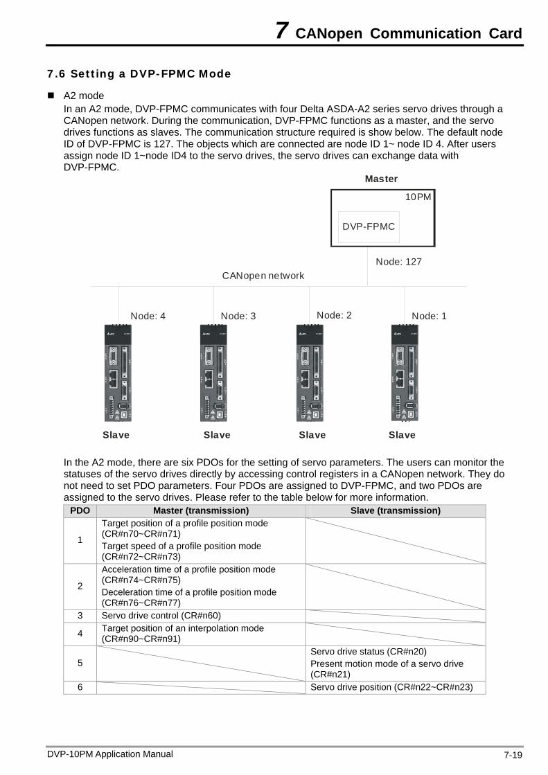
7 CANopen Communication Card
7.6 Setting a DVP-FPMC Mode
A2 mode In an A2 mode, DVP-FPMC communicates with four Delta ASDA-A2 series servo drives through a CANopen network. During the communication, DVP-FPMC functions as a master, and the servo drives functions as slaves. The communication structure required is show below. The default node ID of DVP-FPMC is 127. The objects which are connected are node ID 1~ node ID 4. After users assign node ID 1~node ID4 to the servo drives, the servo drives can exchange data with DVP-FPMC.
CANopen network
DVP-FPMC
Node: 127
Node: 1Node: 2Node: 3Node: 4
10PM
Master
SlaveSlaveSlaveSlave
In the A2 mode, there are six PDOs for the setting of servo parameters. The users can monitor the statuses of the servo drives directly by accessing control registers in a CANopen network. They do not need to set PDO parameters. Four PDOs are assigned to DVP-FPMC, and two PDOs are assigned to the servo drives. Please refer to the table below for more information.
PDO Master (transmission) Slave (transmission)
1
Target position of a profile position mode (CR#n70~CR#n71) Target speed of a profile position mode (CR#n72~CR#n73)
2
Acceleration time of a profile position mode (CR#n74~CR#n75) Deceleration time of a profile position mode (CR#n76~CR#n77)
3 Servo drive control (CR#n60)
4 Target position of an interpolation mode (CR#n90~CR#n91)
5 Servo drive status (CR#n20) Present motion mode of a servo drive (CR#n21)
6 Servo drive position (CR#n22~CR#n23)
DVP-10PM Application Manual 7-19
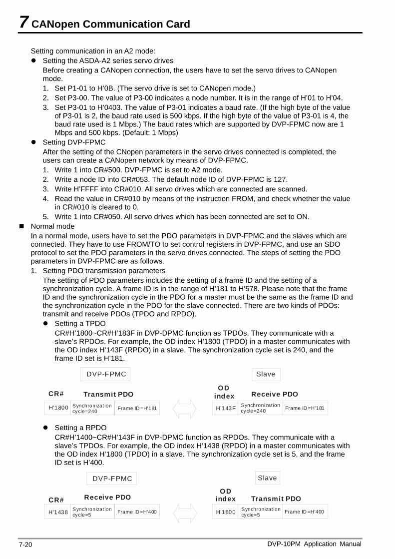
7 CANopen Communication Card
Setting communication in an A2 mode: Setting the ASDA-A2 series servo drives
Before creating a CANopen connection, the users have to set the servo drives to CANopen mode. 1. Set P1-01 to H’0B. (The servo drive is set to CANopen mode.) 2. Set P3-00. The value of P3-00 indicates a node number. It is in the range of H’01 to H’04. 3. Set P3-01 to H’0403. The value of P3-01 indicates a baud rate. (If the high byte of the value
of P3-01 is 2, the baud rate used is 500 kbps. If the high byte of the value of P3-01 is 4, the baud rate used is 1 Mbps.) The baud rates which are supported by DVP-FPMC now are 1 Mbps and 500 kbps. (Default: 1 Mbps)
Setting DVP-FPMC After the setting of the CNopen parameters in the servo drives connected is completed, the users can create a CANopen network by means of DVP-FPMC. 1. Write 1 into CR#500. DVP-FPMC is set to A2 mode. 2. Write a node ID into CR#053. The default node ID of DVP-FPMC is 127. 3. Write H’FFFF into CR#010. All servo drives which are connected are scanned. 4. Read the value in CR#010 by means of the instruction FROM, and check whether the value
in CR#010 is cleared to 0. 5. Write 1 into CR#050. All servo drives which has been connected are set to ON.
Normal mode In a normal mode, users have to set the PDO parameters in DVP-FPMC and the slaves which are connected. They have to use FROM/TO to set control registers in DVP-FPMC, and use an SDO protocol to set the PDO parameters in the servo drives connected. The steps of setting the PDO parameters in DVP-FPMC are as follows. 1. Setting PDO transmission parameters
The setting of PDO parameters includes the setting of a frame ID and the setting of a synchronization cycle. A frame ID is in the range of H’181 to H’578. Please note that the frame ID and the synchronization cycle in the PDO for a master must be the same as the frame ID and the synchronization cycle in the PDO for the slave connected. There are two kinds of PDOs: transmit and receive PDOs (TPDO and RPDO). Setting a TPDO
CR#H’1800~CR#H’183F in DVP-DPMC function as TPDOs. They communicate with a slave’s RPDOs. For example, the OD index H’1800 (TPDO) in a master communicates with the OD index H’143F (RPDO) in a slave. The synchronization cycle set is 240, and the frame ID set is H’181.
Transmit PDO
DVP-FPMC
Receive PDO CR# OD index
Slave
H'1800 Synchronizat ion cycle=240 Frame ID =H'181 H'143F Synchronizat ion
cycle=240 Frame ID =H'181
Setting a RPDO
CR#H’1400~CR#H’143F in DVP-DPMC function as RPDOs. They communicate with a slave’s TPDOs. For example, the OD index H’1438 (RPDO) in a master communicates with the OD index H’1800 (TPDO) in a slave. The synchronization cycle set is 5, and the frame ID set is H’400.
DVP-FPMC
Receive PDO
H'1438 Synchronizat ion cycle=5 Frame ID =H'400 H'1800
Transmit PDO CR#OD
index
Slave
Synchronizat ion cycle=5 Frame ID =H'400
DVP-10PM Application Manual 7-20
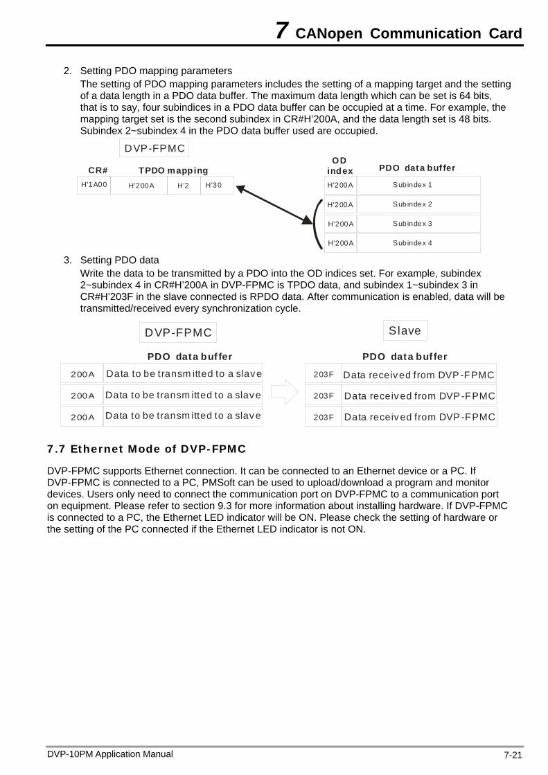
7 CANopen Communication Card
2. Setting PDO mapping parameters The setting of PDO mapping parameters includes the setting of a mapping target and the setting of a data length in a PDO data buffer. The maximum data length which can be set is 64 bits, that is to say, four subindices in a PDO data buffer can be occupied at a time. For example, the mapping target set is the second subindex in CR#H’200A, and the data length set is 48 bits. Subindex 2~subindex 4 in the PDO data buffer used are occupied.
H'1A00
TPDO mapping
DVP-FPMC
PDO data buf ferCR#Subindex 1
OD index
Subindex 2
Subindex 3
Subindex 4
H'200A H'30H'2 H'200A
H'200A
H'200A
H'200A
3. Setting PDO data Write the data to be transmitted by a PDO into the OD indices set. For example, subindex 2~subindex 4 in CR#H’200A in DVP-FPMC is TPDO data, and subindex 1~subindex 3 in CR#H’203F in the slave connected is RPDO data. After communication is enabled, data will be transmitted/received every synchronization cycle.
DVP-FPMC
200A
200A
200A
Data to be transm itted to a slave
Data to be transm itted to a slave
Data to be transm itted to a slave
203F
203F
203F
Data received from DVP -FPMC
Data received from DVP -FPMC
Data received from DVP -FPMC
Slave
PDO data buf ferPDO data buf fer
7.7 Ethernet Mode of DVP-FPMC
DVP-FPMC supports Ethernet connection. It can be connected to an Ethernet device or a PC. If DVP-FPMC is connected to a PC, PMSoft can be used to upload/download a program and monitor devices. Users only need to connect the communication port on DVP-FPMC to a communication port on equipment. Please refer to section 9.3 for more information about installing hardware. If DVP-FPMC is connected to a PC, the Ethernet LED indicator will be ON. Please check the setting of hardware or the setting of the PC connected if the Ethernet LED indicator is not ON.
DVP-10PM Application Manual 7-21
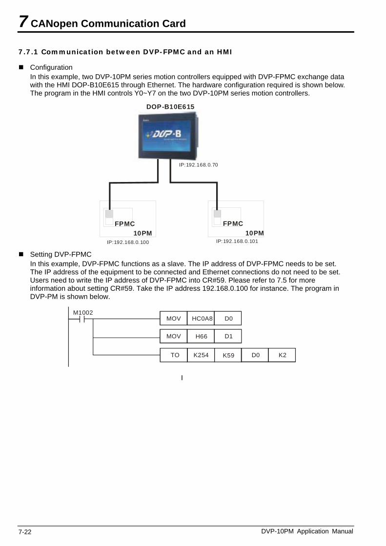
7 CANopen Communication Card
7.7.1 Communication between DVP-FPMC and an HMI
Configuration In this example, two DVP-10PM series motion controllers equipped with DVP-FPMC exchange data with the HMI DOP-B10E615 through Ethernet. The hardware configuration required is shown below. The program in the HMI controls Y0~Y7 on the two DVP-10PM series motion controllers.
FPMC10PM
FPMC10PM
DOP-B10E615
IP:192.168.0.101IP:192.168.0.100
IP:192.168.0.70
Setting DVP-FPMC
In this example, DVP-FPMC functions as a slave. The IP address of DVP-FPMC needs to be set. The IP address of the equipment to be connected and Ethernet connections do not need to be set. Users need to write the IP address of DVP-FPMC into CR#59. Please refer to 7.5 for more information about setting CR#59. Take the IP address 192.168.0.100 for instance. The program in DVP-PM is shown below.
M1002
TO K254 K59 D0 K2
MOV HC0A8 D0
MOV H66 D1
I
DVP-10PM Application Manual 7-22
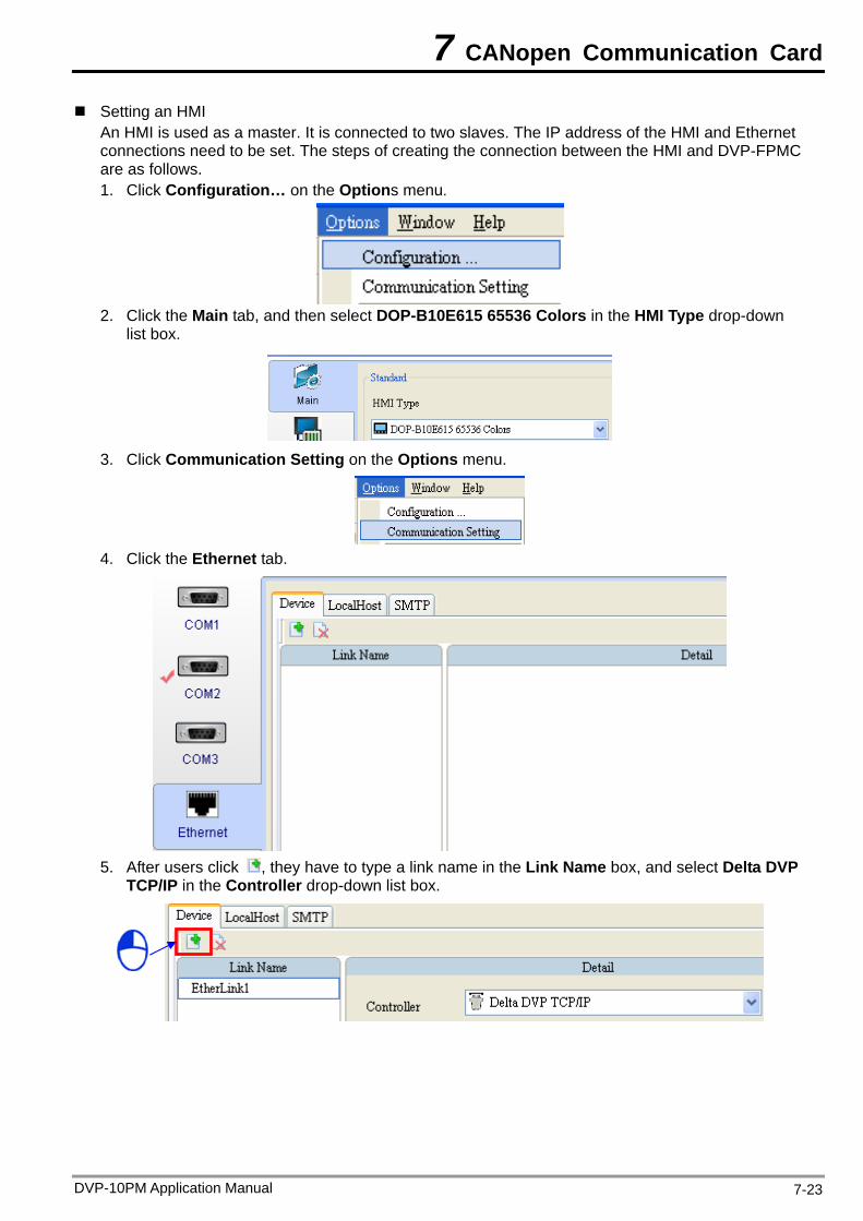
7 CANopen Communication Card
Setting an HMI An HMI is used as a master. It is connected to two slaves. The IP address of the HMI and Ethernet connections need to be set. The steps of creating the connection between the HMI and DVP-FPMC are as follows. 1. Click Configuration… on the Options menu.
2. Click the Main tab, and then select DOP-B10E615 65536 Colors in the HMI Type drop-down
list box.
3. Click Communication Setting on the Options menu.
4. Click the Ethernet tab.
5. After users click , they have to type a link name in the Link Name box, and select Delta DVP
TCP/IP in the Controller drop-down list box.
DVP-10PM Application Manual 7-23
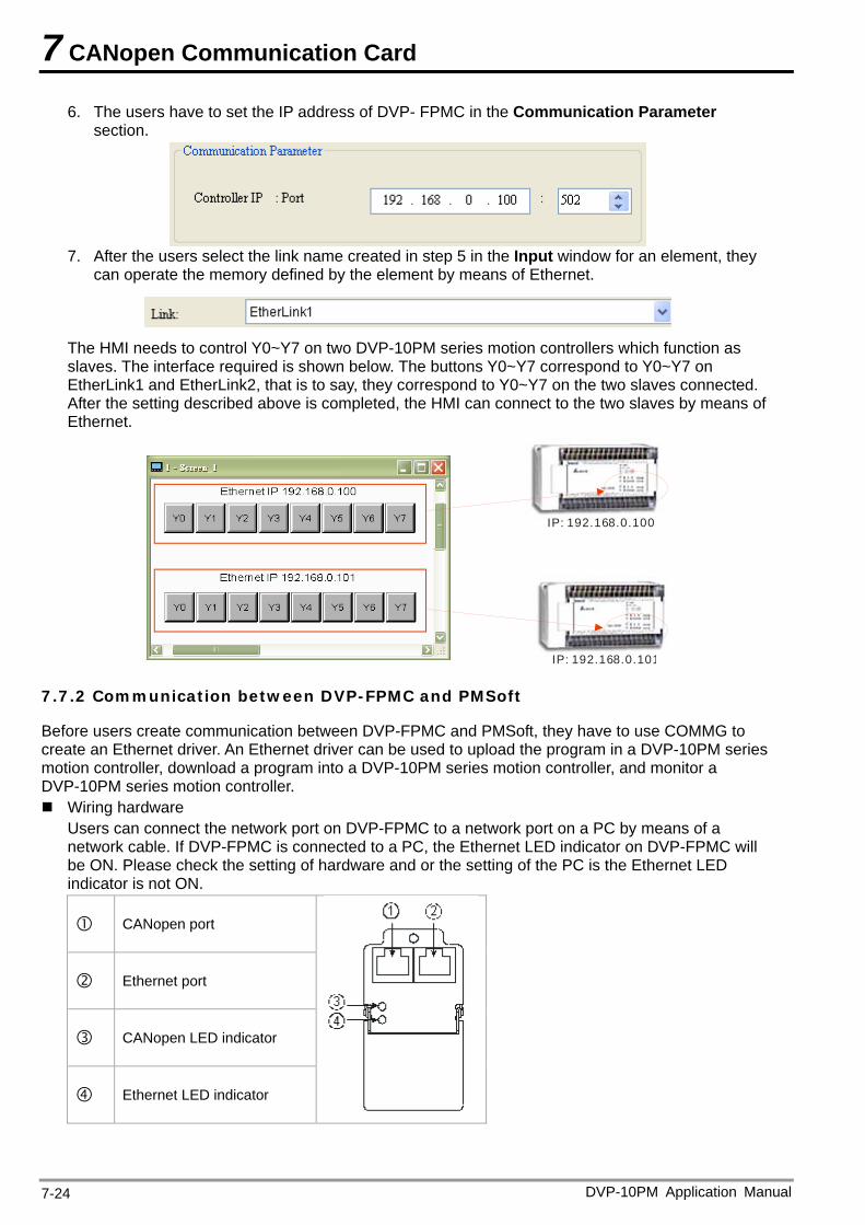
7 CANopen Communication Card
6. The users have to set the IP address of DVP- FPMC in the Communication Parameter section.
7. After the users select the link name created in step 5 in the Input window for an element, they
can operate the memory defined by the element by means of Ethernet.
The HMI needs to control Y0~Y7 on two DVP-10PM series motion controllers which function as slaves. The interface required is shown below. The buttons Y0~Y7 correspond to Y0~Y7 on EtherLink1 and EtherLink2, that is to say, they correspond to Y0~Y7 on the two slaves connected. After the setting described above is completed, the HMI can connect to the two slaves by means of Ethernet.
IP: 192.168.0.100
IP: 192.168.0.101
7.7.2 Communication between DVP-FPMC and PMSoft
Before users create communication between DVP-FPMC and PMSoft, they have to use COMMG to create an Ethernet driver. An Ethernet driver can be used to upload the program in a DVP-10PM series motion controller, download a program into a DVP-10PM series motion controller, and monitor a DVP-10PM series motion controller. Wiring hardware
Users can connect the network port on DVP-FPMC to a network port on a PC by means of a network cable. If DVP-FPMC is connected to a PC, the Ethernet LED indicator on DVP-FPMC will be ON. Please check the setting of hardware and or the setting of the PC is the Ethernet LED indicator is not ON.
CANopen port
Ethernet port
CANopen LED indicator
Ethernet LED indicator
DVP-10PM Application Manual 7-24
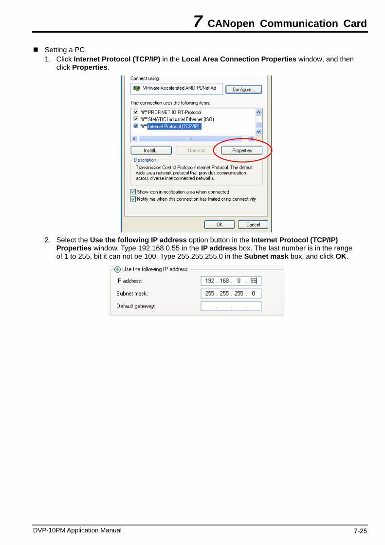
7 CANopen Communication Card
Setting a PC 1. Click Internet Protocol (TCP/IP) in the Local Area Connection Properties window, and then
click Properties.
2. Select the Use the following IP address option button in the Internet Protocol (TCP/IP)
Properties window. Type 192.168.0.55 in the IP address box. The last number is in the range of 1 to 255, bit it can not be 100. Type 255.255.255.0 in the Subnet mask box, and click OK.
DVP-10PM Application Manual 7-25
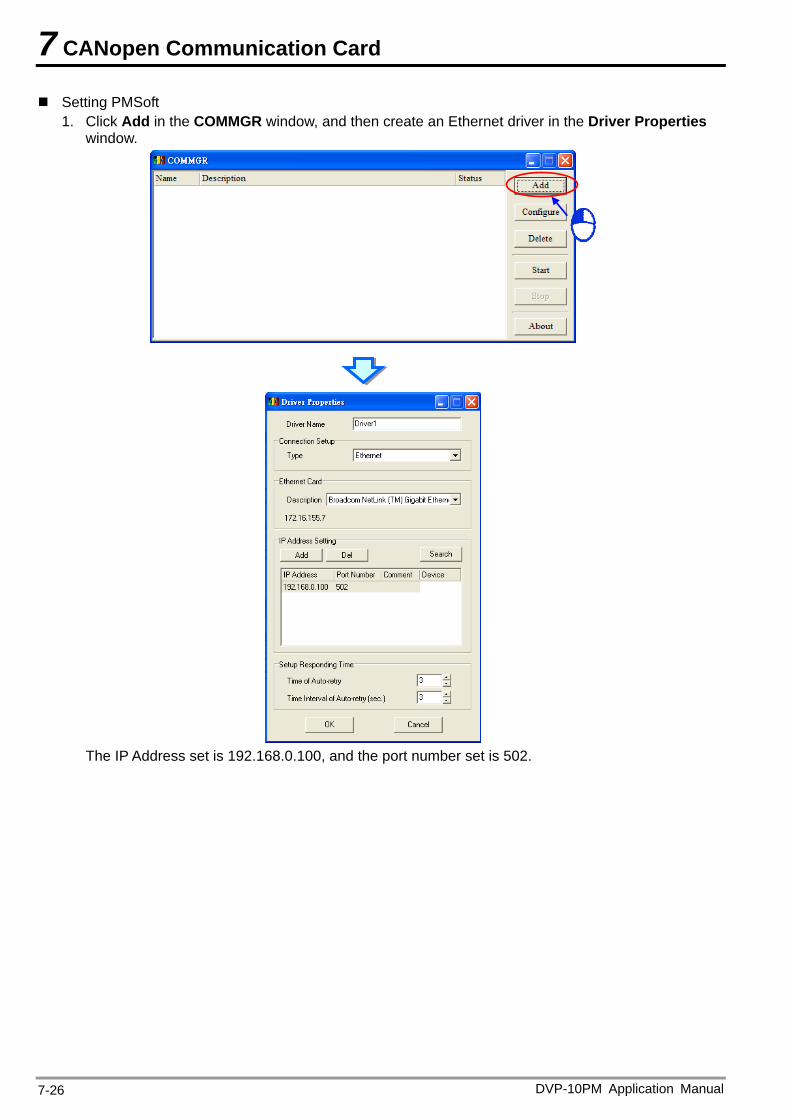
7 CANopen Communication Card
Setting PMSoft 1. Click Add in the COMMGR window, and then create an Ethernet driver in the Driver Properties
window.
The IP Address set is 192.168.0.100, and the port number set is 502.
DVP-10PM Application Manual 7-26
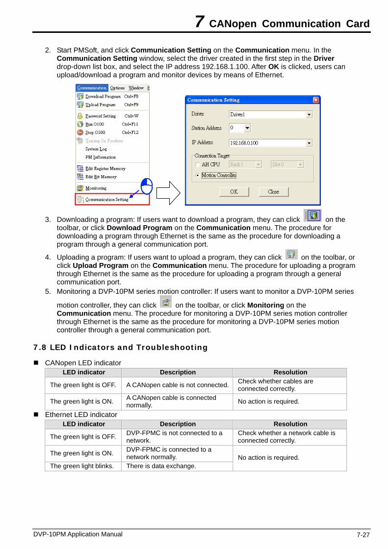
7 CANopen Communication Card
2. Start PMSoft, and click Communication Setting on the Communication menu. In the Communication Setting window, select the driver created in the first step in the Driver drop-down list box, and select the IP address 192.168.1.100. After OK is clicked, users can upload/download a program and monitor devices by means of Ethernet.
3. Downloading a program: If users want to download a program, they can click on the toolbar, or click Download Program on the Communication menu. The procedure for downloading a program through Ethernet is the same as the procedure for downloading a program through a general communication port.
4. Uploading a program: If users want to upload a program, they can click on the toolbar, or click Upload Program on the Communication menu. The procedure for uploading a program through Ethernet is the same as the procedure for uploading a program through a general communication port.
5. Monitoring a DVP-10PM series motion controller: If users want to monitor a DVP-10PM series
motion controller, they can click on the toolbar, or click Monitoring on the Communication menu. The procedure for monitoring a DVP-10PM series motion controller through Ethernet is the same as the procedure for monitoring a DVP-10PM series motion controller through a general communication port.
7.8 LED Indicators and Troubleshooting
CANopen LED indicator LED indicator Description Resolution
The green light is OFF. A CANopen cable is not connected. Check whether cables are connected correctly.
The green light is ON. A CANopen cable is connected normally. No action is required.
Ethernet LED indicator LED indicator Description Resolution
The green light is OFF. DVP-FPMC is not connected to a network.
Check whether a network cable is connected correctly.
The green light is ON. DVP-FPMC is connected to a network normally.
The green light blinks. There is data exchange. No action is required.
DVP-10PM Application Manual 7-27

7 CANopen Communication Card
DVP-10PM Application Manual 7-28
MEMO
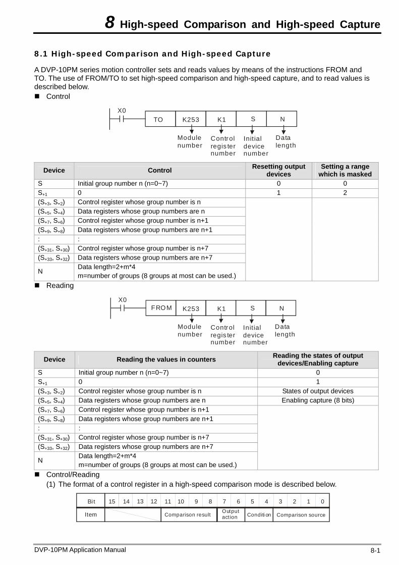
8 High-speed Comparison and High-speed Capture
DVP-10PM Application Manual 8-1
8.1 High-speed Comparison and High-speed Capture
A DVP-10PM series motion controller sets and reads values by means of the instructions FROM and TO. The use of FROM/TO to set high-speed comparison and high-speed capture, and to read values is described below. Control
X0TO K253 K1 S N
Control regis ter number
Init ial device number
Module number
Data length
Device Control Resetting output devices
Setting a range which is masked
S Initial group number n (n=0~7) 0 0 S+1 0 1 2 (S+3, S+2) Control register whose group number is n (S+5, S+4) Data registers whose group numbers are n (S+7, S+6) Control register whose group number is n+1 (S+9, S+8) Data registers whose group numbers are n+1 : : (S+31, S+30) Control register whose group number is n+7 (S+33, S+32) Data registers whose group numbers are n+7
N Data length=2+m*4 m=number of groups (8 groups at most can be used.)
Reading
X0K253 K1 S N
Control regis ter number
Init ial device
Module number
number
Data length
FROM
Device Reading the values in counters Reading the states of output devices/Enabling capture
S Initial group number n (n=0~7) 0 S+1 0 1 (S+3, S+2) Control register whose group number is n States of output devices (S+5, S+4) Data registers whose group numbers are n Enabling capture (8 bits) (S+7, S+6) Control register whose group number is n+1 (S+9, S+8) Data registers whose group numbers are n+1 : : (S+31, S+30) Control register whose group number is n+7 (S+33, S+32) Data registers whose group numbers are n+7
N Data length=2+m*4 m=number of groups (8 groups at most can be used.)
Control/Reading (1) The format of a control register in a high-speed comparison mode is described below.
0123456789101112131415
Comparison sourceComparison result
Bi t
Item Conditi onOutput act ion
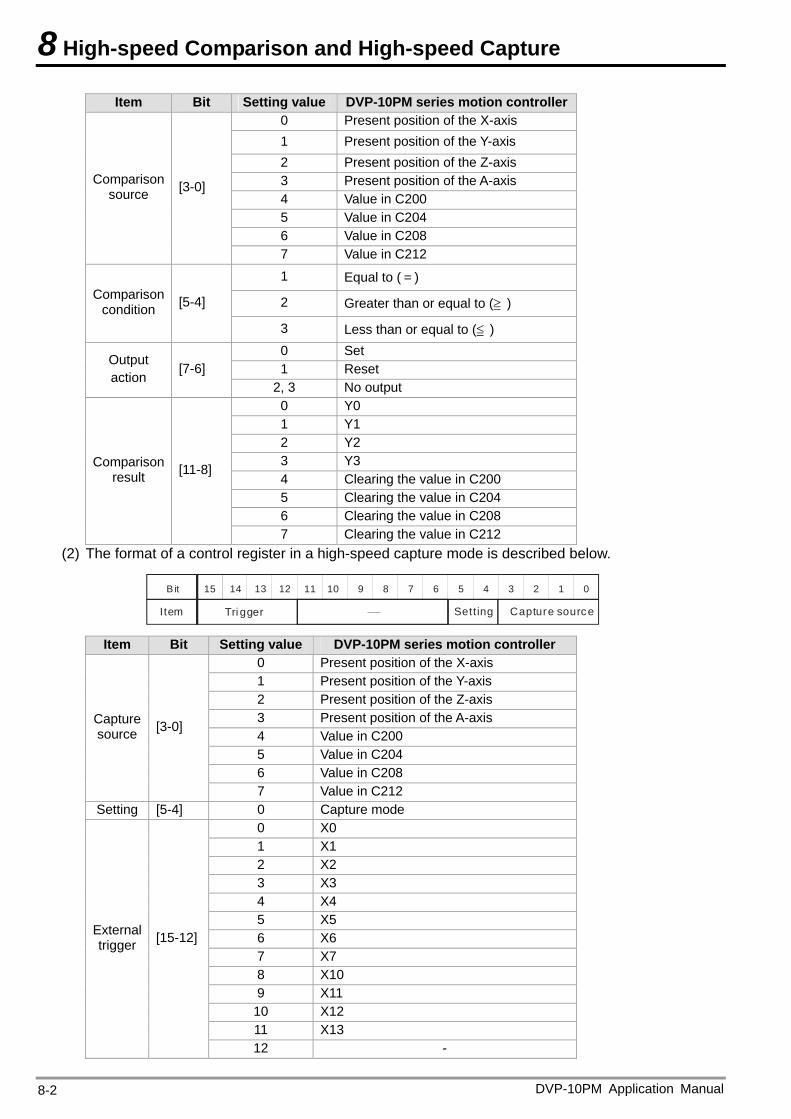
8 High-speed Comparison and High-speed Capture
Item Bit Setting value DVP-10PM series motion controller 0 Present position of the X-axis 1 Present position of the Y-axis 2 Present position of the Z-axis 3 Present position of the A-axis 4 Value in C200 5 Value in C204 6 Value in C208
Comparison source [3-0]
7 Value in C212
1 Equal to (=)
2 Greater than or equal to (≧ ) Comparison
condition [5-4]
3 Less than or equal to (≦ ) 0 Set 1 Reset
Output action [7-6]
2, 3 No output 0 Y0 1 Y1 2 Y2 3 Y3 4 Clearing the value in C200 5 Clearing the value in C204 6 Clearing the value in C208
Comparison result [11-8]
7 Clearing the value in C212 (2) The format of a control register in a high-speed capture mode is described below.
0123456789101112131415
Capture source
B it
Item SettingTri gger
Item Bit Setting value DVP-10PM series motion controller 0 Present position of the X-axis 1 Present position of the Y-axis 2 Present position of the Z-axis 3 Present position of the A-axis 4 Value in C200 5 Value in C204 6 Value in C208
Capture source [3-0]
7 Value in C212 Setting [5-4] 0 Capture mode
0 X0 1 X1 2 X2 3 X3 4 X4 5 X5 6 X6 7 X7 8 X10 9 X11
10 X12 11 X13
External trigger [15-12]
12 -
DVP-10PM Application Manual 8-2
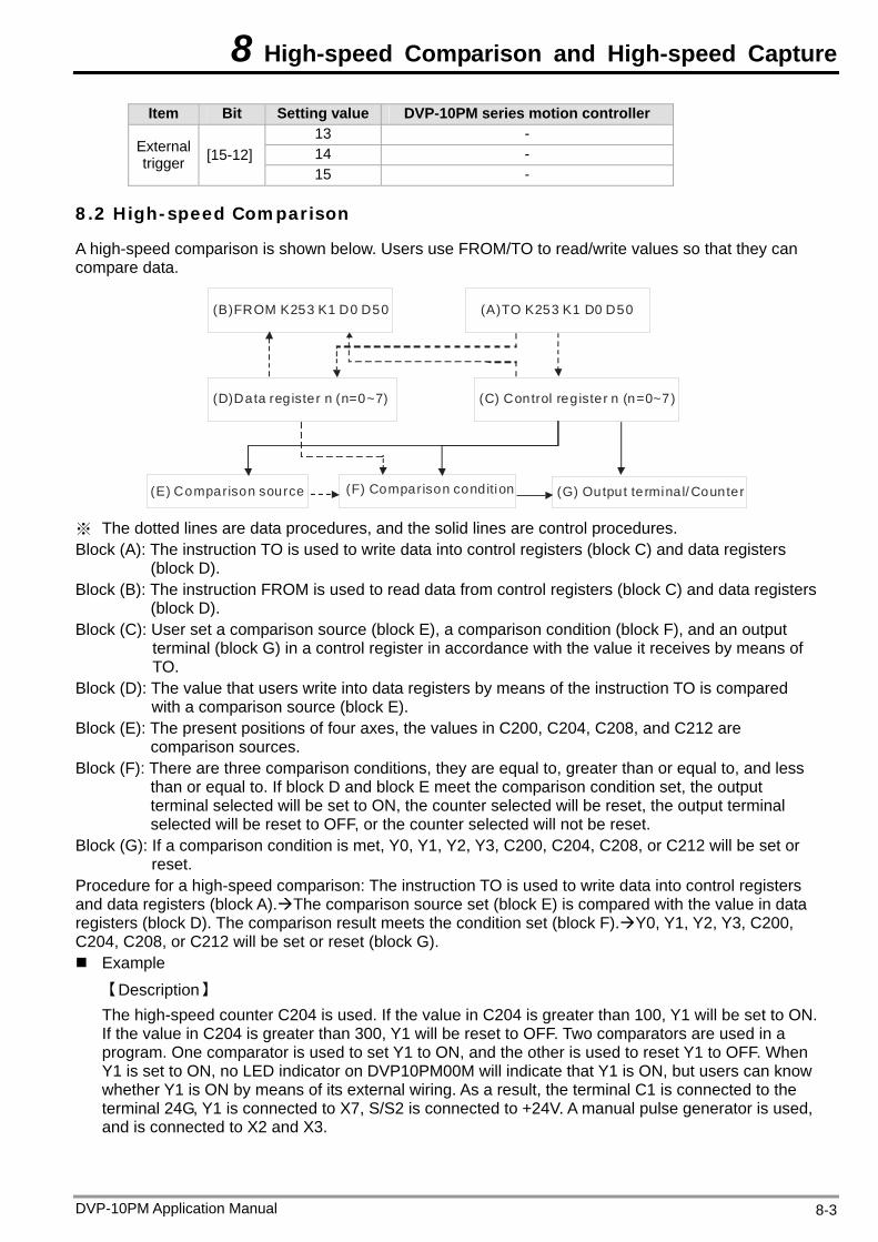
8 High-speed Comparison and High-speed Capture
DVP-10PM Application Manual 8-3
Item Bit Setting value DVP-10PM series motion controller 13 - 14 - External
trigger [15-12] 15 -
8.2 High-speed Comparison
A high-speed comparison is shown below. Users use FROM/TO to read/write values so that they can compare data.
(B)FROM K253 K1 D0 D50 (A)TO K253 K1 D0 D50
(D)Data reg ister n (n=0~7) (C) Control reg ister n (n=0~7)
(E) Comparison source (F) Comparison condition (G) Output terminal/ Counter
※ The dotted lines are data procedures, and the solid lines are control procedures. Block (A): The instruction TO is used to write data into control registers (block C) and data registers
(block D). Block (B): The instruction FROM is used to read data from control registers (block C) and data registers
(block D). Block (C): User set a comparison source (block E), a comparison condition (block F), and an output
terminal (block G) in a control register in accordance with the value it receives by means of TO.
Block (D): The value that users write into data registers by means of the instruction TO is compared with a comparison source (block E).
Block (E): The present positions of four axes, the values in C200, C204, C208, and C212 are comparison sources.
Block (F): There are three comparison conditions, they are equal to, greater than or equal to, and less than or equal to. If block D and block E meet the comparison condition set, the output terminal selected will be set to ON, the counter selected will be reset, the output terminal selected will be reset to OFF, or the counter selected will not be reset.
Block (G): If a comparison condition is met, Y0, Y1, Y2, Y3, C200, C204, C208, or C212 will be set or reset.
Procedure for a high-speed comparison: The instruction TO is used to write data into control registers and data registers (block A).The comparison source set (block E) is compared with the value in data registers (block D). The comparison result meets the condition set (block F).Y0, Y1, Y2, Y3, C200, C204, C208, or C212 will be set or reset (block G). Example
【Description】 The high-speed counter C204 is used. If the value in C204 is greater than 100, Y1 will be set to ON. If the value in C204 is greater than 300, Y1 will be reset to OFF. Two comparators are used in a program. One comparator is used to set Y1 to ON, and the other is used to reset Y1 to OFF. When Y1 is set to ON, no LED indicator on DVP10PM00M will indicate that Y1 is ON, but users can know whether Y1 is ON by means of its external wiring. As a result, the terminal C1 is connected to the terminal 24G, Y1 is connected to X7, S/S2 is connected to +24V. A manual pulse generator is used, and is connected to X2 and X3.
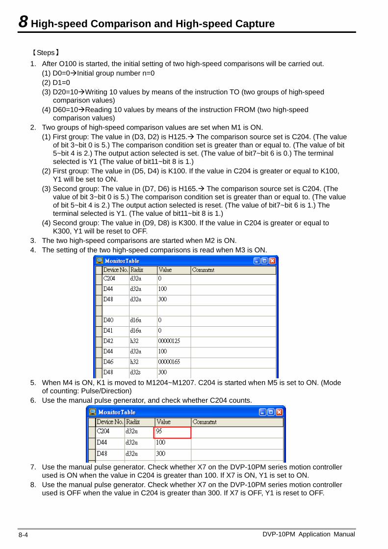
8 High-speed Comparison and High-speed Capture
【Steps】 1. After O100 is started, the initial setting of two high-speed comparisons will be carried out.
(1) D0=0Initial group number n=0 (2) D1=0 (3) D20=10Writing 10 values by means of the instruction TO (two groups of high-speed
comparison values) (4) D60=10Reading 10 values by means of the instruction FROM (two high-speed
comparison values) 2. Two groups of high-speed comparison values are set when M1 is ON.
(1) First group: The value in (D3, D2) is H125. The comparison source set is C204. (The value of bit 3~bit 0 is 5.) The comparison condition set is greater than or equal to. (The value of bit 5~bit 4 is 2.) The output action selected is set. (The value of bit7~bit 6 is 0.) The terminal selected is Y1 (The value of bit11~bit 8 is 1.)
(2) First group: The value in (D5, D4) is K100. If the value in C204 is greater or equal to K100, Y1 will be set to ON.
(3) Second group: The value in (D7, D6) is H165. The comparison source set is C204. (The value of bit 3~bit 0 is 5.) The comparison condition set is greater than or equal to. (The value of bit 5~bit 4 is 2.) The output action selected is reset. (The value of bit7~bit 6 is 1.) The terminal selected is Y1. (The value of bit11~bit 8 is 1.)
(4) Second group: The value in (D9, D8) is K300. If the value in C204 is greater or equal to K300, Y1 will be reset to OFF.
3. The two high-speed comparisons are started when M2 is ON. 4. The setting of the two high-speed comparisons is read when M3 is ON.
5. When M4 is ON, K1 is moved to M1204~M1207. C204 is started when M5 is set to ON. (Mode
of counting: Pulse/Direction) 6. Use the manual pulse generator, and check whether C204 counts.
7. Use the manual pulse generator. Check whether X7 on the DVP-10PM series motion controller
used is ON when the value in C204 is greater than 100. If X7 is ON, Y1 is set to ON. 8. Use the manual pulse generator. Check whether X7 on the DVP-10PM series motion controller
used is OFF when the value in C204 is greater than 300. If X7 is OFF, Y1 is reset to OFF.
DVP-10PM Application Manual 8-4
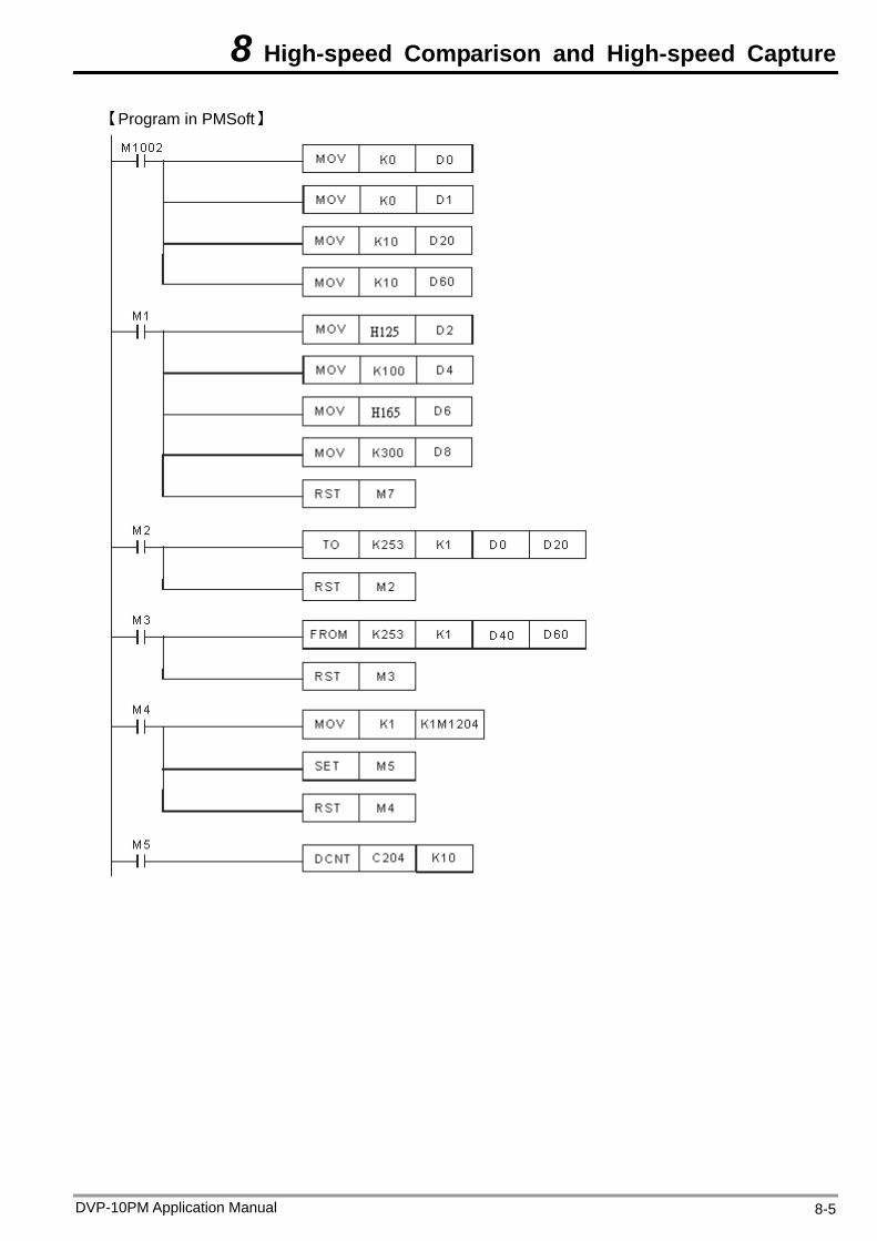
8 High-speed Comparison and High-speed Capture
【Program in PMSoft】
DVP-10PM Application Manual 8-5
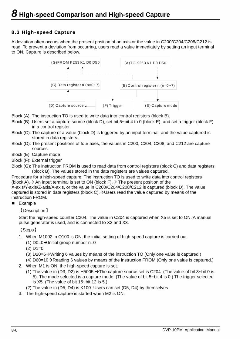
8 High-speed Comparison and High-speed Capture
8.3 High-speed Capture
A deviation often occurs when the present position of an axis or the value in C200/C204/C208/C212 is read. To prevent a deviation from occurring, users read a value immediately by setting an input terminal to ON. Capture is described below.
(C) Data reg ister n (n=0~7) (B) Contro l reg ister n (n=0~7)
(D) Capture source
(G)FROM K253 K1 D0 D50 (A)TO K253 K1 D0 D50
(F) Trigger (E) Capture mode
Block (A): The instruction TO is used to write data into control registers (block B). Block (B): Users set a capture source (block D), set bit 5~bit 4 to 0 (block E), and set a trigger (block F)
in a control register. Block (C): The capture of a value (block D) is triggered by an input terminal, and the value captured is
stored in data registers. Block (D): The present positions of four axes, the values in C200, C204, C208, and C212 are capture
sources. Block (E): Capture mode Block (F): External trigger Block (G): The instruction FROM is used to read data from control registers (block C) and data registers
(block B). The values stored in the data registers are values captured. Procedure for a high-speed capture: The instruction TO is used to write data into control registers (block A). An input terminal is set to ON (block F). The present position of the X-axis/Y-axis/Z-axis/A-axis, or the value in C200/C204/C208/C212 is captured (block D). The value captured is stored in data registers (block C).Users read the value captured by means of the instruction FROM. Example
【Description】 Start the high-speed counter C204. The value in C204 is captured when X5 is set to ON. A manual pulse generator is used, and is connected to X2 and X3.
【Steps】 1. When M1002 in O100 is ON, the initial setting of high-speed capture is carried out.
(1) D0=0Initial group number n=0 (2) D1=0 (3) D20=6Writing 6 values by means of the instruction TO (Only one value is captured.) (4) D60=10Reading 6 values by means of the instruction FROM (Only one value is captured.)
2. When M1 is ON, the high-speed capture is set. (1) The value in (D3, D2) is H5005.The capture source set is C204. (The value of bit 3~bit 0 is
5). The mode selected is a capture mode. (The value of bit 5~bit 4 is 0.) The trigger selected is X5. (The value of bit 15~bit 12 is 5.)
(2) The value in (D5, D4) is K100. Users can set (D5, D4) by themselves. 3. The high-speed capture is started when M2 is ON.
DVP-10PM Application Manual 8-6
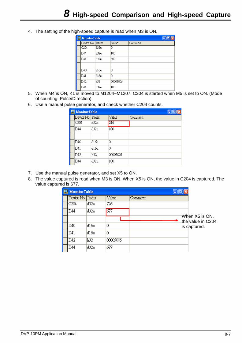
8 High-speed Comparison and High-speed Capture
4. The setting of the high-speed capture is read when M3 is ON.
5. When M4 is ON, K1 is moved to M1204~M1207. C204 is started when M5 is set to ON. (Mode
of counting: Pulse/Direction) 6. Use a manual pulse generator, and check whether C204 counts.
7. Use the manual pulse generator, and set X5 to ON. 8. The value captured is read when M3 is ON. When X5 is ON, the value in C204 is captured. The
value captured is 677.
When X5 is ON, the value in C204 is captured.
DVP-10PM Application Manual 8-7
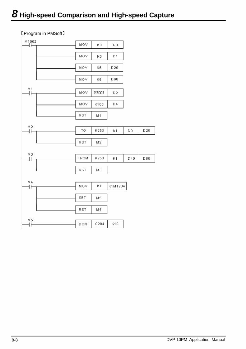
8 High-speed Comparison and High-speed Capture
【Program in PMSoft】
DVP-10PM Application Manual 8-8
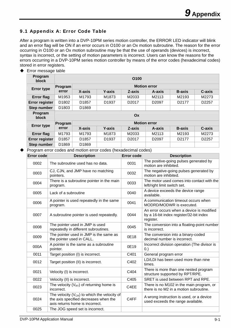
9 Appendix
9.1 Appendix A: Error Code Table
After a program is written into a DVP-10PM series motion controller, the ERROR LED indicator will blink and an error flag will be ON if an error occurs in O100 or an Ox motion subroutine. The reason for the error occurring in O100 or an Ox motion subroutine may be that the use of operands (devices) is incorrect, syntax is incorrect, or the setting of motion parameters is incorrect. Users can know the reasons for the errors occurring in a DVP-10PM series motion controller by means of the error codes (hexadecimal codes) stored in error registers. Error message table
Program block O100
Motion error Error type Program error X-axis Y-axis Z-axis A-axis B-axis C-axis
Error flag M1953 M1793 M1873 M2033 M2113 M2193 M2273 Error register D1802 D1857 D1937 D2017 D2097 D2177 D2257 Step number D1803 D1869
Program block Ox
Motion error Error type Program error X-axis Y-axis Z-axis A-axis B-axis C-axis
Error flag M1793 M1793 M1873 M2033 M2113 M2193 M2273 Error register D1857 D1857 D1937 D2017 D2097 D2177 D2257 Step number D1869 D1869
Program error codes and motion error codes (hexadecimal codes) Error code Description Error code Description
0002 The subroutine used has no data. 0031 The positive-going pulses generated by motion are inhibited.
0003 CJ, CJN, and JMP have no matching pointers. 0032 The negative-going pulses generated by
motion are inhibited.
0004 There is a subroutine pointer in the main program. 0033 The motor used comes into contact with the
left/right limit switch set.
0005 Lack of a subroutine 0040 A device exceeds the device range available.
0006 A pointer is used repeatedly in the same program. 0041 A communication timeout occurs when
MODRD/MODWR is executed.
0007 A subroutine pointer is used repeatedly. 0044 An error occurs when a device is modified by a 16-bit index register/32-bit index register.
0008 The pointer used in JMP is used repeatedly in different subroutines. 0045 The conversion into a floating-point number
is incorrect.
0009 The pointer used in JMP is the same as the pointer used in CALL. 0E18 The conversion into a binary-coded
decimal number is incorrect.
000A A pointer is the same as a subroutine pointer. 0E19 Incorrect division operation (The divisor is
0.) 0011 Target position (I) is incorrect. C401 General program error
0012 Target position (II) is incorrect. C402 LD/LDI has been used more than nine times.
0021 Velocity (I) is incorrect. C404 There is more than one nested program structure supported by RPT/RPE.
0022 Velocity (II) is incorrect. C405 SRET is used between RPT and RPE.
0023 The velocity (VRT) of returning home is incorrect. C4EE There is no M102 in the main program, or
there is no M2 in a motion subroutine.
0024 The velocity (VCR) to which the velocity of the axis specified decreases when the axis returns home is incorrect.
C4FF A wrong instruction is used, or a device used exceeds the range available.
0025 The JOG speed set is incorrect.
DVP-10PM Application Manual 9-1

9 Appendix
DVP-10PM Application Manual 9-2
MEMO


![FXCPU Structured Programming Manual [Application Functions] · FXCPU Structured Programming Manual [Application Functions] FXCPU Structured Programming Manual [Application Functions]](https://img.pdfslide.us/doc/110x75/5f7c3a0ec7c4c4492f38781e/fxcpu-structured-programming-manual-application-functions-fxcpu-structured-programming.jpg)