Embed Size (px)
Citation preview

SKF Vibracon chocks 2014-08-25
Application guidelines
SKF Vibracon chocks
SKF Solution Factory – Marine Services
Contact e-mail address: [email protected]

Page 2 of 37
SKF Vibracon chocks 2014-08-25
1 Executive Summary
SKF Vibracon chocks are permanent, strong and re-usable mounting
chocks for all types of rotating or critically aligned machinery. SKF Vibracon
chocks are mechanically stiff chocks that make accurate mounting and
alignment simple and quick. The SKF Vibracon chock advantages are its
adjustability characteristics, reusability features and the capability to
create the perfect mounting plane within minutes. This makes SKF
Vibracon chock the most economical means to establish precision mounting
and alignment between equipment and foundation.
The SKF Vibracon chock has many configurations and material options to
satisfy technical demands, in end user environments and production line
costs. All SKF Vibracon chocks include the spherical top plate and mating
middle section. This self-leveling configuration accommodates angular
differences up to 4°.
In this manual SKF will inform you about all aspects of the SKF Vibracon. If
you have further questions or if you need additional information, please
remember that SKF Solution Factory - Marine Services is a 24/7 local
organization. Do not hesitate to contact us by phone or e-mail.
Contact e-mail address: [email protected] Phone number: +31 (0)180 48 38 28

Page 3 of 37
SKF Vibracon chocks 2014-08-25
Table of content
1 EXECUTIVE SUMMARY ........................................................................ 2
2 MARKET .......................................................................................... 4
3 THE APPLICATIONS ........................................................................... 5
3.1 Application description ....................................................................... 5
3.1.1 Where to use an SKF Vibracon chock? ................................................................ 5
3.1.2 The need for precise and quick alignment. .......................................................... 5
3.1.3 The need for quick re-alignment. ....................................................................... 5
3.1.4 The need to reduce unplanned failures – To secure vital uptime. ............................ 5
3.1.5 The need of compact and maintenance free designs. ............................................ 6
3.1.6 The need for global availability .......................................................................... 6
4 THE PROPOSAL ................................................................................. 7
4.1 Offer description ............................................................................... 7
4.2 Technical details ............................................................................... 7
4.2.1 SKF Vibracon (type SM) .................................................................................... 7
4.2.2 SKF Vibracon low profile chock (type SM LP) ..................................................... 12
4.2.3 SKF spherical washer (type SMSW) .................................................................. 14
4.2.4 SKF spherical washer low profile (type SMSW LP) ............................................... 16
4.2.5 Additional bottom rings .................................................................................. 17
4.2.6 Extended top plate ........................................................................................ 18
4.2.7 Mounting kits ................................................................................................ 18
4.3 Maintenance and Handling ............................................................... 19
4.4 Mounting and dismounting ............................................................... 23
5 UNIQUE BUYING POINTS .................................................................. 25
5.1 Offer Features ................................................................................ 25
5.2 The Benefits ................................................................................... 25
5.3 Technical advantages ...................................................................... 25
5.4 Commercial advantages ................................................................... 26
6 VARIOUS APPLICATIONS: .................................................................. 27
7 DATASHEETS .................................................................................. 31
8 MOUNTING PROPOSAL ...................................................................... 35

Page 4 of 37
SKF Vibracon chocks 2014-08-25
2 Market
Industry overview
The origin of the SKF Vibracon chock products can be found in a marine
environment. However, the product is applied in many more industries. When components are pre-mounted on a steel base frame, a so called skid,
the necessity for initial and final alignment is apparent. Also for concrete mounted components. The Vibracon does have an impressive track record.
The SKF Vibracon products are known within the following markets and
applications:
- Compressors
- Electric motors
- Industrial fans
- Industrial pumps
- Industrial transmissions
- Machine tools
- Marine / Navy
- Material handling
- Medical and health care
- Metals
- Mining, mineral processing and cement
- Oil and gas / Offshore
- Pulp and paper
- Railways
- Solar energy
- Traditional power
- Wind energy

Page 5 of 37
SKF Vibracon chocks 2014-08-25
3 The Applications
3.1 Application description
3.1.1 Where to use an SKF Vibracon chock?
- Critical rotating equipment - Eliminate soft foot
- Angular difference between machine and the mounting base - Require alignment - Short time frame, no curing time epoxy
- Height adjustment - Request for re-alignment
When to use an SKF Vibracon?
3.1.2 The need for precise and quick alignment.
To avoid noise and vibrations it is critical to have the machinery optimal
aligned. Optimal alignment works also positive on the wear and tear inside the machinery and reduces energy losses and fuel consumption. With the
SKF Vibracon chock the optimal alignment can be reached so the shafts are operating in line and creates an optimal lifetime of the bearings.
3.1.3 The need for quick re-alignment.
Whenever due to for example transport the alignment needs to be
optimised with SKF Vibracon chocks it is very easy to correct the misalignment. This corrective activity needs to go precise, easy and fast.
This to make sure the machinery is operational quickly and without a need for intensive labour.
3.1.4 The need to reduce unplanned failures – To secure vital uptime.
The SKF Vibracon chocks are tightened with decent forces so that the SKF
Vibracon will remain in the same position during operation of the

Page 6 of 37
SKF Vibracon chocks 2014-08-25
machinery. The SKF Vibracon chock has the features from a rigid arrangement combined with benefits to change heights after installation.
3.1.5 The need of compact and maintenance free designs.
By introducing the low profile version the SKF Vibracon chock can also be
used in limited chocking heights. This is also helpful in case of conversion from a grouted chocking to a re-adjustable SKF Vibracon.
3.1.6 The need for global availability
The globalization trend has increased the need of high global availability.
Just-in-time concepts together with multinational production and assembly
put high demands of a highly available distribution chain of components. SKF just has that.

Page 7 of 37
SKF Vibracon chocks 2014-08-25
4 The Proposal
4.1 Offer description
The SKF Vibracon chock is a universal re-adjustable steel chock. Universal
refers to the fact that an SKF Vibracon chock can be used instead of rigid
steel chocks, shims or epoxy resin chocks. Re-adjustable refers to the
possibility of aligning and re-adjusting the chock at every re-alignment
event. The name ”Vibracon” suggests that the elements can absorb
vibrations like a vibration damper.
It is important to realize that the SKF Vibracon chock is absolutely not a
vibration damper (resilient mount).
4.2 Technical details
4.2.1 SKF Vibracon (type SM)
SKF Vibracon chocks are machinery mounting chocks that can be easily
and accurately adjusted. The chocks have the ability to accommodate up to
a 4° angular difference between machine and the mounting base. The SKF
Vibracon chock is installed within a short time-span, mainly without the
need of expensive or invasive machining of the mounting base. The
products’ self-levelling and height-adjustment features eliminate the
possibility of a soft foot during the life cycle of the machinery. Soft foot
resists when one or more feet of a machine differ in height from the
others.
The SKF Vibracon chock: Quick, Easy, Accurate.
Available in
Standard (CS) DIN 1.1191 / 1.0570 Stock item Stainless Steel (SS) DIN 1.4404 (AISI 316L) Stock item
Alloy Steel (AS) DIN 1.7225 Stock item K-Monel 500 (KM) QQ-N-286 On request
Treated (CS-TR) Stock item

Page 8 of 37
SKF Vibracon chocks 2014-08-25
Figure 1: SKF Vibracon chock photo
Figure 2:SKF Vibracon chock (type SM) set up
Figure 3: SKF Vibracon chock (Type SM)
Besides our standard range or materials there is the option to choose for a treated SKF Vibracon chock. When SKF Vibracons are used in humid and
salty climates, an additional protector might be beneficial. In these conditions we recommend to use treated elements.
SKF Vibracon chock
SKF spherical washer
Vibracon
SKF washer

Page 9 of 37
SKF Vibracon chocks 2014-08-25
Stre
ngt
h
Corrosion resistance
SKF Vibracon Chock
+
Heavy duty
Carbon steel treated Carbon Steel
Stainless
+
Metric
Figure 4
Table 1
Vibracon type DIN 1.1191
Carbon Steel
Prodmast code
Bolt hole
[mm]
Height [mm]
Diameter [mm]
SM 12 -CS 9291040012100000100 17 30 – 38 60
SM 16 -CS 9291040016100000100 21 35 – 45 80
SM 20 -CS 9291040020100000100 25 40 – 50 100
SM 24 -CS 9291040024100000100 31 45 – 57 120
SM 30 -CS 9291040030100000100 37 50 – 62 140
SM 36 -CS 9291040036100000100 44 55 – 67 160
SM 42 -CS 9291040042100000100 50 60 – 72 190
SM 48 -CS 9291040048100000100 60 70 – 85 220
SM 56 -CS 9291040056100000100 66 75 – 90 230
SM 64 -CS 9291040064100000100 74 80 - 95 250

Page 10 of 37
SKF Vibracon chocks 2014-08-25
Table 2
Table 3
The SKF Stainless steel Vibracon chocks are applicable in very demanding conditions, like offshore, on deck, or under water equipment.
Vibracon type DIN 1.1191
Carbon Steel
Prodmast code
Bolt hole
[mm]
Height [mm]
Diameter [mm]
SM 12 –CSTR 9291040012105100100 17 30 – 38 60
SM 16 –CSTR 9291040016105100100 21 35 – 45 80
SM 20 –CSTR 9291040020105100100 25 40 – 50 100
SM 24 –CSTR 9291040024105100100 31 45 – 57 120
SM 30 –CSTR 9291040030105100100 37 50 – 62 140
SM 36 –CSTR 9291040036105100100 44 55 – 67 160
SM 42 –CSTR 9291040042105100100 50 60 – 72 190
SM 48 –CSTR 9291040048105100100 60 70 – 85 220
SM 56 –CSTR 9291040056105100100 66 75 – 90 230
SM 64 –CSTR 9291040064105100100 74 80 - 95 250
Vibracon type DIN1.4404
Stainless Steel
Prodmast code
Bolt hole [mm]
Height [mm]
Diameter [mm]
SM 12 -SS 9291040012110000100 17 30 – 38 60
SM 16 -SS 9291040016110000100 21 35 – 45 80
SM 20 -SS 9291040020110000100 25 40 – 50 100
SM 24 -SS 9291040024110000100 31 45 – 57 120
SM 30 -SS 9291040030110000100 37 50 – 62 140
SM 36 -SS 9291040036110000100 44 55 – 67 160
SM 42 -SS 9291040042110000100 50 60 – 72 190
SM 48 -SS 9291040048110000100 60 70 – 85 220
SM 56 -SS 9291040056110000100 66 75 – 90 230
SM 64 -SS 9291040064110000100 74 80 - 95 250

Page 11 of 37
SKF Vibracon chocks 2014-08-25
Imperial
Table 4
Table 5
Table 6
Vibracon type DIN1.1191
Carbon Steel
Prodmast code
Bolt hole [inch]
Height [inch]
Diameter [inch]
SM 12 -CS 9291040012100000100 0.67 1.18 – 1.50 2.36
SM 16 -CS 9291040016100000100 0.83 1.38 – 1.77 3.15
SM 20 -CS 9291040020100000100 0.98 1.57 – 1.97 3.94
SM 24 -CS 9291040024100000100 1.22 1,77 – 2.24 4.72
SM 30 -CS 9291040030100000100 1.46 1.97 – 2.44 5.51
SM 36 -CS 9291040036100000100 1.73 2.17 – 2.64 6.30
SM 42 -CS 9291040042100000100 1.97 2.36 – 2.83 7.48
SM 48 -CS 9291040048100000100 2.36 2.76 – 3.35 8.66
SM 56 -CS 9291040056100000100 2.60 2.95 – 3.54 9.06
SM 64 -CS 9291040064100000100 2.91 3.15 – 3.74 9.84
Vibracon type DIN1.1191
Carbon Steel
Prodmast code
Bolt hole [inch]
Height [inch]
Diameter [inch]
SM 12 –CSTR 9291040012105100100 0.67 1.18 – 1.50 2.36
SM 16 –CSTR 9291040016105100100 0.83 1.38 – 1.77 3.15
SM 20 –CSTR 9291040020105100100 0.98 1.57 – 1.97 3.94
SM 24 –CSTR 9291040024105100100 1.22 1,77 – 2.24 4.72
SM 30 –CSTR 9291040030105100100 1.46 1.97 – 2.44 5.51
SM 36 –CSTR 9291040036105100100 1.73 2.17 – 2.64 6.30
SM 42 –CSTR 9291040042105100100 1.97 2.36 – 2.83 7.48
SM 48 –CSTR 9291040048105100100 2.36 2.76 – 3.35 8.66
SM 56 –CSTR 9291040056105100100 2.60 2.95 – 3.54 9.06
SM 64 –CSTR 9291040064105100100 2.91 3.15 – 3.74 9.84
Vibracon type DIN1.4404
Stainless Steel
Prodmast code
Bolt hole [inch]
Height [inch]
Diameter [inch]
SM 12 -SS 9291040012110000100 0.67 1.18 – 1.50 2.36
SM 16 -SS 9291040016110000100 0.83 1.38 – 1.77 3.15
SM 20 -SS 9291040020110000100 0.98 1.57 – 1.97 3.94
SM 24 -SS 9291040024110000100 1.22 1,77 – 2.24 4.72
SM 30 -SS 9291040030110000100 1.46 1.97 – 2.44 5.51
SM 36 -SS 9291040036110000100 1.73 2.17 – 2.64 6.30
SM 42 -SS 9291040042110000100 1.97 2.36 – 2.83 7.48
SM 48 -SS 9291040048110000100 2.36 2.76 – 3.35 8.66
SM 56 -SS 9291040056110000100 2.60 2.95 – 3.54 9.06
SM 64 -SS 9291040064110000100 2.91 3.15 – 3.74 9.84
Page 12 of 37
SKF Vibracon chocks 2014-08-25
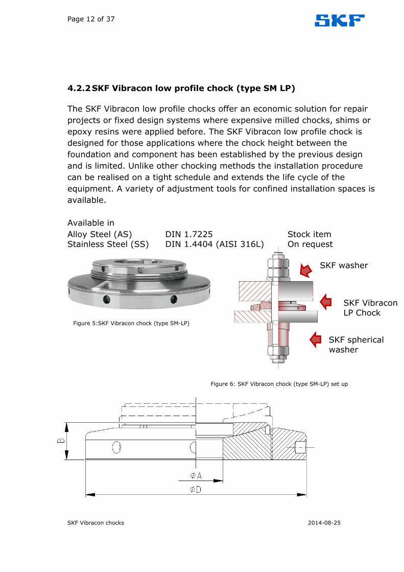
4.2.2 SKF Vibracon low profile chock (type SM LP)
The SKF Vibracon low profile chocks offer an economic solution for repair
projects or fixed design systems where expensive milled chocks, shims or
epoxy resins were applied before. The SKF Vibracon low profile chock is
designed for those applications where the chock height between the
foundation and component has been established by the previous design
and is limited. Unlike other chocking methods the installation procedure
can be realised on a tight schedule and extends the life cycle of the
equipment. A variety of adjustment tools for confined installation spaces is
available.
Available in
Alloy Steel (AS) DIN 1.7225 Stock item Stainless Steel (SS) DIN 1.4404 (AISI 316L) On request
Figure 5:SKF Vibracon chock (type SM-LP)
Figure 6: SKF Vibracon chock (type SM-LP) set up
SKF Vibracon LP Chock
SKF spherical washer
SKF washer

Page 13 of 37
SKF Vibracon chocks 2014-08-25
Figure 7: SKF Vibracon chock (Type SM LP) Metric
Table 7
table 8
Imperial
Table 9
Other materials available on request. Mail to: [email protected]
Vibracon type
DIN 1.7225
Alloy Steel
Product code
Bolt hole [mm]
Height [mm]
Diameter [mm]
SM 16 LP-AS 9291040016100020100 21 20 – 30 80
SM 20 LP-AS 9291040020100020100 25 20 – 30 100
SM 24 LP-AS 9291040024100020100 31 20 – 30 120
SM 30 LP-AS 9291040030100020100 37 20 – 30 140
SM 36 LP-AS 9291040036100020100 44 30 – 40 160
SM 42 LP-AS 9291040042100020100 50 35 – 45 190
Vibracon type
DIN 1.7225
Alloy Steel
Product code
Bolt hole [mm]
Height [mm]
Diameter [mm]
SM 16 LP-ASTR 9291055016125100100 21 20 – 30 80
SM 20 LP-ASTR 9291055020125100100 25 20 – 30 100
SM 24 LP-ASTR 9291055024125100100 31 20 – 30 120
SM 30 LP-ASTR 9291055030125100100 37 20 – 30 140
SM 36 LP-ASTR 9291055036125100100 44 30 – 40 160
SM 42 LP-ASTR 9291055042125100100 50 35 – 45 190
Vibracon type
DIN 1.7225
Alloy Steel
Product code
Bolt hole [inch]
Height [inch]
Diameter [inch]
SM 16 LP-AS 9291040016100020100 0.83 0.79 – 1.18 3.15
SM 20 LP-AS 9291040020100020100 0.98 0.79 – 1.18 3.94
SM 24 LP-AS 9291040024100020100 1.22 0.79 – 1.18 4.72
SM 30 LP-AS 9291040030100020100 1.46 0.79 – 1.18 5.51
SM 36 LP-AS 9291040036100020100 1.73 1.18 – 1.57 6.30
SM 42 LP-AS 9291040042100020100 1.97 1.38 – 1.77 7.48

Page 14 of 37
SKF Vibracon chocks 2014-08-25
4.2.3 SKF spherical washer (type SMSW)
SKF spherical washers are designed to create an exact parallel plane between the bolt head and the face of the nut.
The main advantages are:
Prevent the need for spot-facing. It automatically adjusts to compensate for angular faults.
Bolt tension is evenly distributed. Increased bolt stretch due to increased clamping length.
Use of high-grade alloy steel gives reduces chance of failure. Eliminates bolt bending.
Reduces bolt fatigue.
Another major advantage of the SKF spherical washer is that it has been
engineered to easily machine down its own height. Standard SKF spherical washers come in alloy steel (AS). SKF stock the standard height and low
profile version.
Figure 9: SKF spherical washer (type SW) set up
Figure 8 Figure 10
SKF spherical washer (to prevent the need for
spot facing)

Page 15 of 37
SKF Vibracon chocks 2014-08-25
Table 10
Table 11
The height of the SKF spherical washer is 60mm/2,36 inch for all types.
Article no.
Product code Metric Imperial
D[mm] d[mm] D[inch] D[inch]
SMSW 16 -AS 9291047016120000100 33 17 1.30 0.67
SMSW 20 -AS 9291047020120000100 42 23 1.65 0.91
SMSW 24 -AS 9291056024120000100 47 27 1.85 1.06
SMSW 27 -AS 9291056027120000100 52 30 2.05 1.18
SMSW 30 -AS 9291056030120000100 56 34 2.20 1.34
SMSW 36 -AS 9291056036120000100 67 40 2.64 1.57
SMSW 42 -AS 9291047048120000100 82 46 3.23 1.81
SMSW 48 -AS 9291047056120000100 92 52 3.62 2.05
SMSW 56 –AS 9291047056120000100 102 59 4.02 2.32
SMSW 64 -AS 9291047064120000100 112 66 4.41 2.60
Article no.
Product code Metric Imperial
D[mm] d[mm] D[inch] D[inch]
SMSW 16 –ASTR 9291047016125100100 33 17 1.30 0.67
SMSW 20 –ASTR 9291047020125100100 42 23 1.65 0.91
SMSW 24 –ASTR 9291047024125100100 47 27 1.85 1.06
SMSW 27 –ASTR 9291047027125100100 52 30 2.05 1.18
SMSW 30 –ASTR 9291047030125100100 56 34 2.20 1.34
SMSW 36 –ASTR 9291047036125100100 67 40 2.64 1.57
SMSW 42 –ASTR 9291047042125100100 82 46 3.23 1.81
SMSW 48 –ASTR 9291047048125100100 92 52 3.62 2.05
SMSW 56 –ASTR 9291047056125100100 102 59 4.02 2.32
SMSW 64 -ASTR 9291047064125100100 112 66 4.41 2.60

Page 16 of 37
SKF Vibracon chocks 2014-08-25
4.2.4 SKF spherical washer low profile (type SMSW LP)
Figure 11
Table 12
Table 13
Other materials and sizes are available on request.
Mail to: [email protected]
Article
no.
Product code Metric Imperial Height (H)
D[mm] d[mm] D[inch] d[inch] Metric[mm] Imperial[inch]
SMSW
16 LP-AS 9291056016120000100 33 17 1.30 0.67 20 0.79
SMSW
20 LP-AS 9291056020120000100 42 23 1.65 0.91 22 0.87
SMSW
24 LP-AS 9291047027120000100 47 27 1.85 1.06 24 0.94
SMSW
27 LP-AS 9291047030120000100 52 30 2.05 1.18 26 1.02
SMSW
30 LP-AS 9291047036120000100 56 34 2.20 1.34 28 1.10
SMSW
36 LP-AS 9291047042120000100 67 40 2.64 1.57 30 1.18
SMSW
42 LP-AS 9291056048120000100 82 46 3.23 1.81 34 1.34
Article
no.
Product code Metric Imperial Height (H)
D[mm] d[mm] D[inch] d[inch] Metric[mm] Imperial[inch]
SMSW
16 LP-
ASTR
9291056016125100100 33 17 1.30 0.67 20 0.79
SMSW
20 LP-
ASTR
9291056020125100100 42 23 1.65 0.91 22 0.87
SMSW
24 LP-
ASTR
9291056024125100100 47 27 1.85 1.06 24 0.94
SMSW
27 LP-
ASTR
9291056027125100100 52 30 2.05 1.18 26 1.02
SMSW
30 LP-
ASTR
9291056030125100100 56 34 2.20 1.34 28 1.10
SMSW
36 LP-
ASTR
9291056036125100100 67 40 2.64 1.57 30 1.18
SMSW
42 LP-
ASTR
9291056042125100100 82 46 3.23 1.81 34 1.34

Page 17 of 37
SKF Vibracon chocks 2014-08-25
4.2.5 Additional bottom rings
It can be that the maximum element height is not sufficient to bridge the
gap between the mounting surface and the bed plate of the component.
Here it is possible to place an additional bottom ring in order to extend the
maximum height of the SKF Vibracon original and low profile chocks. This
ring will be mounted between the base plate of the chock and the top plate
of the foundation. As an alternative for the additional bottom ring SKF
Solution Factory - Marine Services can also provide SKF Vibracon additional
bottom rings. As a rule of thumb, the height of the chocks should not
exceed the diameter of the elements. For instance the maximum height of
an SKF Vibracon SM30, with a diameter of 140 mm, can go up to a chock
height of 140 mm; with the maximum height of the SM30 of 62 mm this
means a maximum height of the Additional Bottom Ring of 78 mm.
Figure 12: additional bottom ring
Article
code
Diameter metric Diameter imperial Height (H)
D[mm] d[mm] D[inch] d[inch]
ABR-12 66 40 2.36 1.57
To be
specified by
customer
ABR-16 86 50 3.15 1.97
ABR-20 106 60 3.94 2.36
ABR-24 126 80 4.72 3.15
ABR-30 146 95 5.51 3.74
ABR-36 166 105 6.30 4.13
ABR-42 196 125 7.48 4.92
ABR-48 226 155 8.66 6.10
ABR-56 236 165 9.06 6.50
ABR-64 256 185 9.84 7.28
Table 14
Material: St.52-3, C45N or 42CrMo4V. Other materials are available on request.

Page 18 of 37
SKF Vibracon chocks 2014-08-25
4.2.6 Extended top plate
It can be that the maximum element height is not sufficient to bridge the gap between the mounting surface and the bed plate of the component.
Alternatively to the additional bottom ring there is also the possibility to order an extended top plate. This option is on request and applicable when
clients have a preference for having 3 components.
Figure 13: extended top plate
4.2.7 Mounting kits
An SKF mounting kit offers the SKF Vibracon chock together with all
elements needed for accurate installation. This all-in-one mounting kit may
include:
- SKF Vibracon elements
- Additional bottom rings
- SKF spherical washers
- Foundation bolts
- Fitting bolts
- Nuts
- Castle nuts (and pins)
- SKF Vibracon bolt torque calculation
- Plan approval certificate of the classification of your choice
- Material certificates bolting material
Figure 14: Mounting kit

Page 19 of 37
SKF Vibracon chocks 2014-08-25
4.3 Maintenance and Handling
A detailed video on the installation procedure of the SKF Vibracon chock is
available online via www.vibracon.com. Below the steps of the installation
procedure are described.
Step 1 Check foundation quality
a. The bottom ring area of the SKF Vibracon chock should be in full
contact (100%) with the foundation surface.
b. The spherical top part of the chock must have at least 75%
contact with the machine foot.
c. When necessary, any foundation roughness is sandblasted with a
quality of Sa 2.5 minimum or machined Ra 6.3.
d. The contact surface between foundation and bottom ring of the
SKF Vibracon chock should be checked using the bottom ring of
the element, until an evenly distributed bearing surface is
reached. The minimum of this bearing surface is given by the
machinery manufacturer or classification society. In all other
cases, we recommend a minimum bearing surface of 75%.
e. The taper between foundation and machine feet should be less
than 4°.
f. Foundation and machine foot should be free from paint and
grease.
Step 2 The SKF Vibracon chocks’ thread and spherical layers are
protected with Molykote®. The chocks are ready for installation
directly from the package after cleaning the surface!
SKF Solution Factory - Marine Services recommends the use of:
Molykote® type P37 on the screw thread;
Molykote® type TP42 on the convex / concave mating
surface.

Page 20 of 37
SKF Vibracon chocks 2014-08-25
Step 3 Check if the SKF Vibracon chock is placed concentric with the bolt
hole.
Step 4 Alignment of machine.
Keep in mind while aligning the machine to add 0.10 mm
(0.004”) to the target alignment because of the fact that the SKF
Vibracon chock will compress slightly at the moment the
foundation bolts are secured. A feeler gauge can be used to check
if the topplate is in full contact with the bottom of the machinery
feet.
Step 5 Fine-tuning SKF Vibracon heights
When executing the alignment, the SKF Vibracon assists without
the need for trial and error, typical for shims. The table below will assist you to fine-tune the chock height of the SKF vibracons.
Height adjustment
Vibracon type Number of adjustment
holes Thread Pitch 1 hole 1/2 hole
[mm] [mm] [mm]
SM 12 6 1 0,167 0,083
SM 16 8 1,5 0,188 0,094
SM 20 8 2 0,250 0,125
SM 24 8
2 0,250 0,125
SM 30 8
2 0,250 0,125
SM 36 8
2 0,250 0,125
SM 42 8 2 0,250 0,125
SM 48 8 3 0,375 0,188
SM 56 10
3 0,300 0,150
SM 64 10 3 0,300 0,150
SM 80 12 4 0,333 0,167
Table 15

Page 21 of 37
SKF Vibracon chocks 2014-08-25
Step 6 Tighten the foundation bolts. SKF Solution Factory - Marine
Services recommends doing this in several steps (in line with SKF
handbook). During or after tightening of the foundation bolts
recheck the alignment and check for "soft foot". A "soft foot"
occurs if one or more of the SKF Vibracon chocks are not carrying
the same load as the other elements.
Step 7 The bolt tension must be checked after the test run.
SKF Solution Factory - Marine Services recommends the use of
SKF spherical washers in the bolt connection.
If you have any questions, please contact SKF Solution Factory -
Marine Services: +31-(0)180 483828

Page 22 of 37
SKF Vibracon chocks 2014-08-25
Link to Animation:
Installation SKF Vibracon chock and SKF spherical washer: http://youtu.be/FJOQuCh-xdo
Installation SKF Vibracon low profile chock and SKF spherical washer: http://www.youtube.com/watch?v=W_9cnHUPmHk
Brochure:
http://www.skf.com/binary/12-64540/06686_1_EN-SKF-Vibracon-brochure.pdf

Page 23 of 37
SKF Vibracon chocks 2014-08-25
4.4 Mounting and dismounting
SKF Solution Factory – Marine Services advise to use 8.8 graded bolts, yield strength > 630 N/mm², in SKF Vibracon applications. Make sure that
the foundation bolt has a minimum elongation of: 0,20 mm / 0.08 inch.
There are several alternatives to create enough elongation in the foundation bolt. The commonly used measures are mentioned below:
Creating enough clamping length by using an extension sleeve;
Figure 15: Extension Sleeve
Reducing the shank diameter (contact your local dealer or SKF Solution Factory - Marine Services for a calculation of the
elongation).
Figure 16: Reduced Shank Diameter

Page 24 of 37
SKF Vibracon chocks 2014-08-25
The clamping length is the total distance between bolt head and
nut, this distance is equal to the sum of: o Machine foot thickness (bed plate thickness)
o Final SKF Vibracon height o Foundation thickness (top plate thickness)
o Extension sleeve height (alternatively the length of the SKF spherical washer)
Figure 17: Clamping Length
SKF Solution Factory - Marine Services recommends the use of so called SKF spherical washers, of which the final height will be determined after
the alignment has been performed, to ensure 100% mating surface of bolt head and nut mating surface to prevent bending stresses in the bolt
connection.
Figure 18: SKF spherical washer
SKF Solution Factory - Marine Services recommends using spherical
washers with convex/ concave mating surfaces in steel of convex/ conical. The SKF spherical washers have the capability to optimally transfer the
pretension stresses.

Page 25 of 37
SKF Vibracon chocks 2014-08-25
5 Unique Buying Points
5.1 Offer Features
A perfect fitted chock.
Easy in installation without particular knowledge.
Saving alignment time.
Accurate alignment possible before testing, after testing and
launching.
Easy realignment during the life time of the component.
5.2 The Benefits
The SKF Vibracon chock has many advantages compared to other products
such as epoxy resin and steel shims. The key advantages are listed below:
5.3 Technical advantages
SKF Vibracon chock has many configurations and material options to
satisfy technical requirements, in end user environments and production
line costs.
Re-adjustability.
Quick installation.
Quick re-alignment in case of problems or warranty claims.
With the SKF Vibracon chock no curing time is needed as with epoxy resin,
it eliminates the trial and error alignment process characteristics for the
“mill and shim” method and adjustability during the life cycle of the
machinery.

Page 26 of 37
SKF Vibracon chocks 2014-08-25
5.4 Commercial advantages
The SKF Vibracon chock is the most economical means to establish a
perfect mounting plane within minutes and will provide a repeated benefit
for production or service managers.
In packaged units (like generators, compressors, turbines and pump sets)
the benefits are:
No parallel or angular soft foot problems, even when the skid is
twisted;
No machining of the base frame required;
No on site problems to arrange or install shims;
Re-adjustable;
In combination with laser alignment equipment, alignment time
can be reduced by 50%;
Existing chocking systems, steel chocks or epoxy resin with a
height of only 20 mm, can be replaced by the SKF Vibracon low
profile configuration (depending on SKF Vibracon size).
Available at your local SKF distributor.
Onboard vessels for chocking propulsion units and auxiliary equipment:
No preparation and curing time like epoxy resin chocks;
No time consuming fitting and grinding of rigid steel chocks;
Chocking can be carried out when the ship is still in the dry dock,
the alignment check and (if required) realignment has to be carried
out after the ship has been launched;
No parallel or angular soft foot problems, even if the foundation is
not machined;
No machining of foundation, only locally (where the elements will
be fitted) machining can be done if required.

Page 27 of 37
SKF Vibracon chocks 2014-08-25
6 Various applications:
Figure 19: gearbox installed with rectangular SKF Vibracon chocks, due to limited space
Figure 20: compressor standing on SKF Vibracon chocks

Page 28 of 37
SKF Vibracon chocks 2014-08-25
Figure 21: Electro motor in industry on SKF Vibracon chocks
Figure 22: pump skids

Page 29 of 37
SKF Vibracon chocks 2014-08-25
Figure 23: Detail of bracket with SKF Vibracon to create a fixed point

Page 30 of 37
SKF Vibracon chocks 2014-08-25
Figure 24: Overview of engine mounted on SKF Vibracon chocks on a concrete foundation. The additional delivered plate is for reducing the surface pressure.
Figure 25 and 26: SKF Vibracon chocks in industry

Page 31 of 37
SKF Vibracon chocks 2014-08-25
7 Datasheets
Figure 27: Data sheet for SKF Vibracon chock
Page 32 of 37
SKF Vibracon chocks 2014-08-25
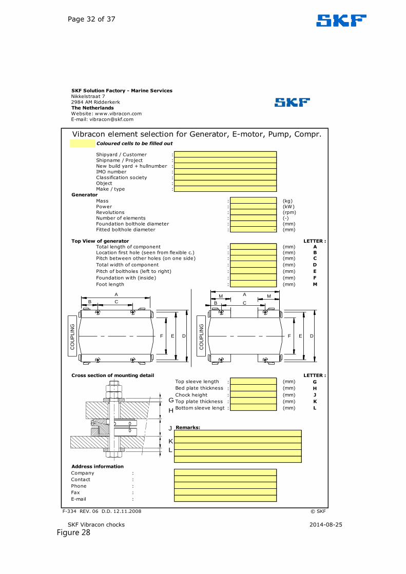
Figure 28
SKF Solution Factory - Marine Services
Coloured cells to be filled out
Shipyard / Customer :
Shipname / Project :
New build yard + hullnumber :
IMO number :
Classification society :
Object :
Make / type :
Generator
Mass : (kg)
Power : (kW)
Revolutions : (rpm)
Number of elements : (-)
Foundation bolthole diameter : (mm)
Fitted bolthole diameter : - (mm)
Top View of generator LETTER :
Total length of component : (mm) A
Location first hole (seen from flexible c.) : (mm) B
Pitch between other holes (on one side) : (mm) C
Total width of component : (mm) D
Pitch of boltholes (left to right) : (mm) E
Foundation with (inside) : (mm) F
Foot length : (mm) M
Cross section of mounting detail LETTER :
Top sleeve length : (mm) G
Bed plate thickness : (mm) H
Chock height : (mm) J
Top plate thickness : (mm) K
Bottom sleeve length: (mm) L
Address information
Company :
Contact :
Phone :
Fax :
E-mail :
F-334 REV. 06 D.D. 12.11.2008 © SKF
Remarks:
E-mail: [email protected]
Nikkelstraat 7
2984 AM Ridderkerk
The Netherlands
Website: www.vibracon.com
Vibracon element selection for Generator, E-motor, Pump, Compr.
CO
UP
LIN
G
CO
UP
LIN
G
F DE F E D
A
CB
A
B
M M
C
G
H
J
K
L

Page 33 of 37
SKF Vibracon chocks 2014-08-25
Figure 29
SKF Solution Factory - Marine Services
Coloured cells to be filled out
Shipyard / Customer :
Shipname / Project :
New build yard + hullnumber :
IMO number :
Classification society :
Object :
Make / type :
Engine
Mass : (kg)
Power : (kW)
Revolutions : (rpm)
Number of elements : (-)
Foundation bolthole diameter : (mm)
Fitted bolthole diameter : (mm)
Top View of engine LETTER :
Total length of engine : (mm) A
Location first hole (seen from flexible c.) : (mm) B
Pitch between other holes (on one side) : (mm) C
Total width of engine : (mm) D
Pitch of boltholes (left to right) : (mm) E
Foundation with (inside) : (mm) F
Cross section of mounting detail LETTER :
Top sleeve length : (mm) G
Bed plate thickness : (mm) H
Chock height : (mm) J
Top plate thickness : (mm) K
Bottom sleeve length: (mm) L
Address information
Company :
Contact :
Phone :
Fax :
E-mail :
F-333 REV. 06 D.D. 12.11.2008 © SKF
Website: www.vibracon.com
E-mail: [email protected]
Nikkelstraat 7
2984 AM Ridderkerk
The Netherlands
Remarks:
Vibracon element selection for Diesel, Gas, Turbine Engines
Stopper clearance in accordancewith manufacturer instructionsSteel side chocks
CO
UP
LIN
G
F E D
B
A
C
G
H
J
K
L

Page 34 of 37
SKF Vibracon chocks 2014-08-25
Figure 30
SKF Solution Factory - Marine Services
Coloured cells to be filled out
Shipyard / Customer :
Shipname / Project :
New build yard + hullnumber :
IMO number :
Classification society :
Object :
Make / type :
Gearbox
Mass : (kg)
Power : (kW)
Revolutions : (rpm)
Number of elements : (-)
Foundation bolthole diameter : (mm)
Fitted bolthole diameter : (mm)
Reduction rate : (-)
Average distance of boltholes : (mm)
Dist. between centre line of shaft and top plate : (mm)
Propulsion efficiency : (N/kW)
(For and aft chocks capable of transmitting 3 times nominal propeller thrust must be installed)
Top View of gearbox LETTER :
Total length of gearbox : (mm) A
Location first hole (seen from flexible c.) : (mm) B
Pitch between other holes (on one side) : (mm) C
Total width of gearbox : (mm) D
Pitch of boltholes (left to right) : (mm) E
Foundation with (inside) : (mm) F
Cross section of mounting detail LETTER :
Top sleeve length : (mm) G
Bed plate thickness : (mm) H
Chock height : (mm) J
Top plate thickness : (mm) K
Bottom sleeve length: (mm) L
Address information
Company :
Contact :
Phone :
Fax :
E-mail :
F-332 REV. 06 D.D. 12.11.2008 © SKF
Vibracon element selection for (Marine) Gearboxes
Remarks:
Website: www.vibracon.com
E-mail: [email protected]
Nikkelstraat 7
2984 AM Ridderkerk
The Netherlands
CO
UP
LIN
G
C B
A
F E D
G
H
J
K
L

Page 35 of 37
SKF Vibracon chocks 2014-08-25
SKF Solution Factory - Marine Services
Phone : +31 (0)180 483828
Fax : +31 (0)180 483829
Shipyard / Customer :
Shipname / Project :
Classification society : C-factor
Object : 5000
Make / type :
MachineMass (if engine with water +oil) : (kg)
Power : (kW)
Revolutions : (rpm)
Foundation width (bolt distance) : (mm)
Number of elements : (-)
Bolthole diameter : (mm)
Correction / Safety factor : (-)
Minimum required Vibracon SM element : (-)
Advised Vibracon SM element : (-)
Element load (maximum) : (kN)
Element load (minimum) : (kN)
Machine load : (kN)
:
Foundation bolts : (-)
Material : (-)
E-modul : 207000 (N/mm²)
Yield stress : (N/mm²)
Elongation foundation bolt : (mm)
Tension per bolt : (kN)
Tensile stress : (N/mm²)
Utilized yield stress : (%)
Von Mises stress (tensile / torsion) : (N/mm²)
Utilized yield stress < 90 % : (%)
Tightening torque : (Nm)
Sheet 1 of 1
Foundation bolt
MS R
EF.
NU
MBER :
Selection of Vibracon SM element
Calculation of holding down bolts' torque
Figure 31
8 Mounting proposal
Figure: 29, 30 and 31

Page 36 of 37
SKF Vibracon chocks 2014-08-25
SKF Solution Factory Marine Services Tel: +31 (0)180 483828 Fax: +31 (0)180 483829 [email protected]
Figure 32

Page 37 of 37
SKF Vibracon chocks 2014-08-25
SKF S
olu
tion F
acto
ry M
arine S
erv
ices
Tel:
+
31 (
0)1
80 4
83828
Fax:
+31 (
0)1
80 4
83829
Vib
racon@
skf.
com
Figure 33