Embed Size (px)
Citation preview

Application Guide
CompensatorsHose AssembliesExpansion Joints
FLEX-WELD.COM
FLEX-WELDI N C O R P O R AT E D
Manufactured By:

Application Guide
What we need to know.......
A. Physical / System ParametersA. Physical / System ParametersA. Physical / System ParametersA. Physical / System Parameters
1Size of Assembly:
Measure Pipe size (ID) of the system
Inches Inches
2Type of Piping Material
Determine piping material being used
Carbon Steel
Copper
Carbon Steel
Copper
3Installed Length (OAL):
Length of pipe measured from anchor to anchor
Inches Inches
4Type of Media:
Indicate if liquid, steam, gas, exhaust, slurry, solids, etc.
5Design Pressure of the System:
Highest/Most severe pressure during operation
Positive PSIG Negative HG
6Operating Pressure:
Acutal Pressure which system works under in normal conditions
Positive PSIG Negative HG
7Temperature of Flowing Media:
Indicate both operating and maximum temperatures of the system
Operating °F Maximum °F
8Temperature of Surrounding Atmosphere:
Indicate both min. & max. termperatures of atmosphere at the expansion joint
Minimum °F Maximum °F
9Velocity of Flowing Media:
In feet/Sec or Gallons/Min
Feet/Sec Gal/Min
10Axial Movement (Compression/Extension):
In inches as a result of system extension/expansion
Compression in Inches Extension in Inches
11Lateral Deflection/Offset:
In inches
Inches Inches
12Angual Movement:
In degrees
Degrees Degrees

Application Guide
B. Product RequirementsB. Product RequirementsB. Product RequirementsB. Product RequirementsB. Product RequirementsB. Product Requirements
1PRODUCT TYPE PRODUCT TYPE PRODUCT TYPE PRODUCT TYPE PRODUCT TYPE
1 COMPENSATOR BRAIDED HOSE EXPANSION JOINT GENERAL PURPOSE PUMP CONNECTOR
2END 1END 1END 1END 1END 1
2 FLANGED ENDS GROOVED ENDS WELD ENDS MALE NPT THREADS FEMALE SWEAT ENDS
Straight
Loop
308
311
10MC
30MC
1207
1407
150#
300#
Plate
Raised Face
Sch 40
Sch 80
Sch 40
Sch 80
Sch 40
Sch 80
Copper
(Compensators & braided hose only)
(Compensators & braided hose only)
(Compensators & braided hose only)
END 2END 2END 2END 2END 2
FLANGED ENDS GROOVED ENDS WELD ENDS MALE NPT THREADS FEMALE SWEAT ENDS
150#
300#
Plate
Raised Face
Sch 40
Sch 80
Sch 40
Sch 80
Sch 40
Sch 80
Copper
(Compensators & braided hose only)
(Compensators & braided hose only)
(Compensators & braided hose only)
Application Guide
Double
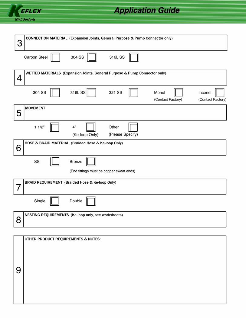
3CONNECTION MATERIAL (Expansion Joints, General Purpose & Pump Connector only)
Carbon Steel 304 SS 316L SS
4WETTED MATERIALS (Expansion Joints, General Purpose & Pump Connector only)
5MOVEMENT
1 1/2” 4”
(Ke-loop Only)
Other
(Please Specify)
6HOSE & BRAID MATERIAL (Braided Hose & Ke-loop Only)
Bronze
(End fittings must be copper sweat ends)
304 SS 316L SS 321 SS Monel(Contact Factory)
Inconel(Contact Factory)
SS
7BRAID REQUIREMENT (Braided Hose & Ke-loop Only)
Single
8NESTING REQUIREMENTS (Ke-loop only, see worksheets)
9
OTHER PRODUCT REQUIREMENTS & NOTES:

Application Guide
Thermal Expansion of Pipe in Inches per 100 Feet Thermal Expansion of Pipe in Inches per 100 Feet Thermal Expansion of Pipe in Inches per 100 Feet Thermal Expansion of Pipe in Inches per 100 Feet Thermal Expansion of Pipe in Inches per 100 Feet Thermal Expansion of Pipe in Inches per 100 Feet Thermal Expansion of Pipe in Inches per 100 Feet Thermal Expansion of Pipe in Inches per 100 Feet Saturated Steam Vacuum in HG below 212°F, Pressure, PSIG above 212°F
Temp. °F Cast Iron Carbon Steel or Steel
Wrought Iron 4-6% Cr. Alloy Steel
18 Cr.-8Ni Stainless Steel
Copper
-200 -1.058 -1.282 -1.289 -1.25 -2.03 -1.955
-180 -0.982 -1.176 -1.183 -1.15 -1.85 -1.782
-160 -0.891 -1.066 -1.073 -1.03 -1.67 -1.612
-140 -0.797 -0.948 -0.955 -0.97 -1.48 -1.428
-120 -0.697 -0.826 -0.833 -0.8 -1.3 -1.235
-100 -0.593 -0.698 -0.705 -0.7 -0.9 -1.04
-80 -0.481 -0.563 -0.57 -0.5 -0.88 -0.835
-60 -0.368 -0.428 -0.435 -0.43 -0.67 -0.63
-40 -0.248 -0.288 -0.295 -0.92 -0.45 -0.421
-20 -0.127 -0.145 -0.152 -0.145 -0.225 -0.21
0 0 0 0 0 0 0
20 0.128 1.148 0.18 0.14 0.223 0.238
32 0.209 0.23 0.28 0.234 0.356 0.366
40 0.27 0.3 0.35 0.28 0.446 0.451
29.39 60 0.41 0.448 0.54 0.43 0.669 0.684
28.89 80 0.55 0.58 0.71 0.5 0.892 0.896
27.99 100 0.68 0.753 0.887 0.65 1.115 1.134
26.48 120 0.83 0.91 1.058 0.8 1.338 1.366
24.04 140 0.97 1.064 1.24 0.95 1.545 1.59
20.27 160 1.11 1.2 1.42 1.1 1.784 1.804
14.63 180 1.24 1.36 1.58 1.25 2 2.051
6.45 200 1.39 1.52 1.75 1.4 2.23 2.296
0 212 1.48 1.61 1.87 1.5 2.361 2.428
2.5 220 1.53 1.68 1.94 1.55 2.46 2.516
10.3 240 1.67 1.84 2.12 1.72 2.68 2.756
20.7 260 1.82 2.02 2.3 1.88 2.92 2.985
34.5 280 1.97 2.18 2.47 2.05 3.15 3.218
52.3 300 2.13 2.35 2.67 2.2 3.39 3.461
74.9 320 2.268 2.53 2.85 2.37 3.615 3.696
103.3 340 2.43 2.7 3.04 2.53 3.84 3.941
138.3 360 2.59 2.88 3.23 2.7 4.1 4.176
180.9 380 2.75 3.06 3.425 2.86 4.346 4.424
232.4 400 2.91 3.23 3.62 3.01 4.58 4.666
293.7 420 3.09 3.421 3.82 3.18 4.8 4.914
366.1 440 3.25 3.595 4.02 3.35 5.05 5.154
451.3 460 3.41 3.784 4.2 3.53 5.3 5.408
550.3 480 3.57 3.955 4.4 3.7 5.54 5.651
664.3 500 3.73 4.151 4.6 3.86 5.8 5.906
795.3 520 3.9 4.342 4.81 4.04 6.05 6.148
945.3 540 4.08 4.525 5.02 4.2 6.28 6.41
1115 560 4.25 4.73 5.22 4.4 6.52 6.646
1308 580 4.43 4.93 5.43 4.56 6.78 6.919
1525 600 4.6 5.13 5.62 4.75 7.02 7.184
1768 620 4.79 5.33 5.84 4.92 7.27 7.432
2041 640 4.97 5.53 6.05 5.1 7.52 7.689
2346 660 5.15 5.75 6.25 5.3 7.77 7.949
2705 680 5.33 5.95 6.47 5.48 8.02 8.196
3080 700 5.52 6.16 6.67 5.65 8.28 8.472
720 5.71 6.36 6.88 5.85 8.52 8.708
740 5.9 6.57 7.1 6.03 8.78 8.999
760 6.09 6.79 7.32 6.22 9.05 9.256
780 6.28 7 7.53 6.41 9.3 9.532
800 6.47 7.23 7.73 6.61 9.58 9.788
820 6.66 7.45 7.96 6.8 9.82 10.068
840 6.85 7.66 7.18 7 10.1 10.308
How to Use the Thermal Expansion Table: Example: Find the expansion 0f 105ft. Of any diameter carbon steel pipe carrying steam at 138 PSIG and at a lowest surrounding ambient temperature of 40°F. ▶ Maximum temperature = 360°F (138 PSIG saturated steam)
▶ Calculated traverse (from table) Expansion per 100 ft. of carbon steel at 360°F = 2.88”
▶ Less expansion per 100 ft. of carbon steel pipe at 40°F = 0.30”
▶ Expected traverse per 100 ft. = 2.58”
Expansion of 105 ft. = (105 / 100) x 2.58” = 2.71” Conclusion: Since an expansion joint is normally set at 80% in compression and 20% in extension, an expansion joint with 4” total axial movement should be selected.
NOTE: The shaded area indicates the maximum and minimum recommended temperature for each material. For applications requiring lower or higher temperatures, consult the factory. From the Piping Handbook by Sabin Crocker, McGraw-Hill Publishing Co. & Acme Paper No. 53-A-52, 1954.
NOTE: Expansion joints are not designed to absorb torsional movement or stress. Subjecting an expansion joint to torsion of any amount may drastically affect operating life and will void the warranty. Consult factory if torsion is present.

Ke-Loop™ L-Flex Nesting Worksheet
Ke-Loop™ V-Flex Nesting Worksheet
V-Flex Nest Position
Pipe ID (inches)
End Fitting
MovementMovementMovement Max . Service
PSI/Temp
Insulation Thickness OAL V-Flex
Distance Between
Pipe Centers
V-Flex Nest Position
Pipe ID (inches)
End Fitting Seismic All
Directions Axial
Compression Axial
Extension
Max . Service
PSI/Temp
Insulation Thickness OAL V-Flex
Distance Between
Pipe Centers
Inner Y1
Middle 1 Y2
Middle 2 Y3
Middle 3 Y4
Outer Y5
L-Flex Nest Position
Pipe ID (inches)
End Fitting
MovementMovementMovement Max . Service
PSI/Temp
Insulation Thickness OAL
Distance Between
Pipe Centers
L-Flex Nest Position
Pipe ID (inches)
End Fitting Seismic All
Directions Axial
Compression Axial
Extension
Max . Service
PSI/Temp
Insulation Thickness OAL
Distance Between
Pipe Centers
Inner
Middle 1
Middle 2
Middle 3
Outer
Application Guide
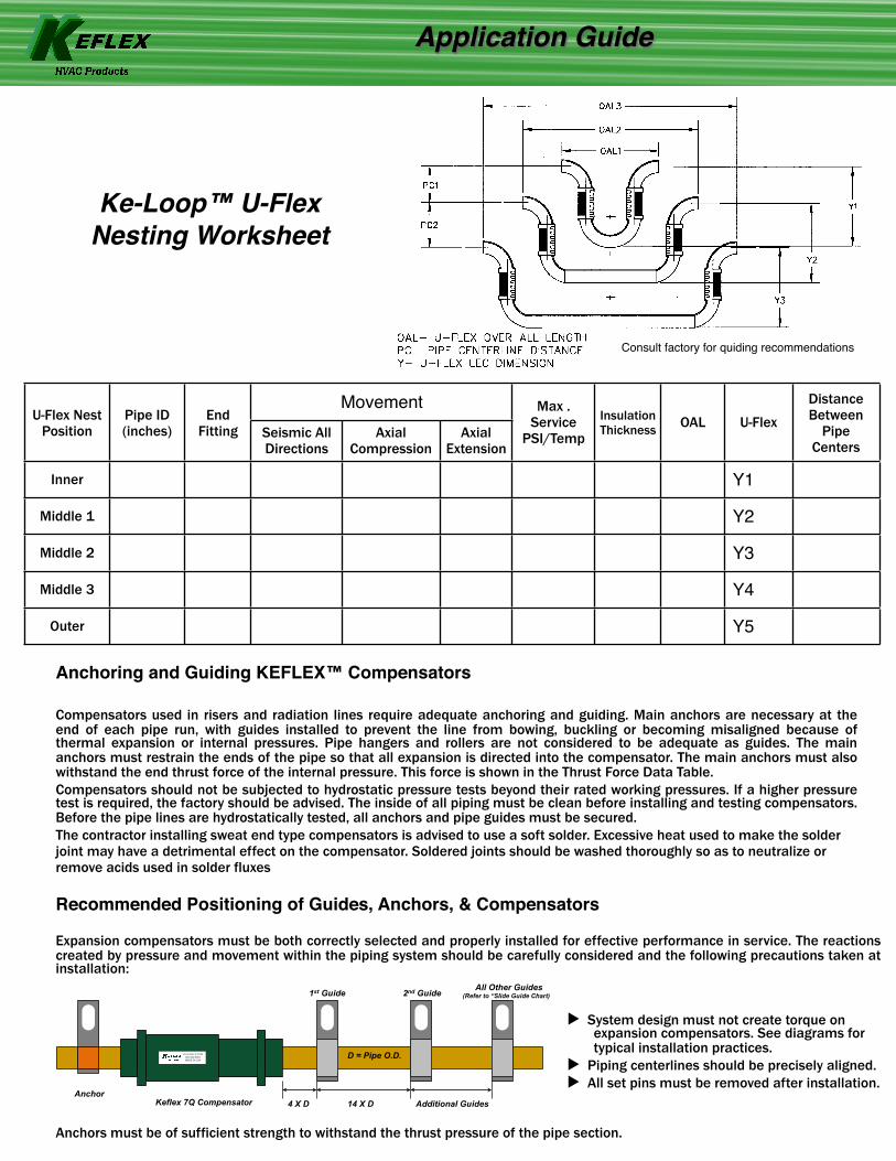
Consult factory for quiding recommendations
Ke-Loop™ U-Flex Nesting Worksheet
U-Flex Nest Position
Pipe ID (inches)
End Fitting
MovementMovementMovement Max . Service
PSI/Temp
Insulation Thickness OAL U-Flex
Distance Between
Pipe Centers
U-Flex Nest Position
Pipe ID (inches)
End Fitting Seismic All
Directions Axial
Compression Axial
Extension
Max . Service
PSI/Temp
Insulation Thickness OAL U-Flex
Distance Between
Pipe Centers
Inner Y1
Middle 1 Y2
Middle 2 Y3
Middle 3 Y4
Outer Y5
Application Guide
Recommended Positioning of Guides, Anchors, & Compensators
▶ System design must not create torque on expansion compensators. See diagrams for typical installation practices.
▶ Piping centerlines should be precisely aligned.▶ All set pins must be removed after installation.
Expansion compensators must be both correctly selected and properly installed for effective performance in service. The reactions created by pressure and movement within the piping system should be carefully considered and the following precautions taken at installation:
Anchors must be of sufficient strength to withstand the thrust pressure of the pipe section.
Anchoring and Guiding KEFLEX™ Compensators
Compensators used in risers and radiation lines require adequate anchoring and guiding. Main anchors are necessary at the end of each pipe run, with guides installed to prevent the line from bowing, buckling or becoming misaligned because of thermal expansion or internal pressures. Pipe hangers and rollers are not considered to be adequate as guides. The main anchors must restrain the ends of the pipe so that all expansion is directed into the compensator. The main anchors must also withstand the end thrust force of the internal pressure. This force is shown in the Thrust Force Data Table.Compensators should not be subjected to hydrostatic pressure tests beyond their rated working pressures. If a higher pressure test is required, the factory should be advised. The inside of all piping must be clean before installing and testing compensators. Before the pipe lines are hydrostatically tested, all anchors and pipe guides must be secured.The contractor installing sweat end type compensators is advised to use a soft solder. Excessive heat used to make the solder joint may have a detrimental effect on the compensator. Soldered joints should be washed thoroughly so as to neutralize or remove acids used in solder fluxes
Keflex 7Q Compensator Anchor
1st Guide 2nd Guide All Other Guides (Refer to “Slide Guide Chart)
4 X D 14 X D Additional Guides
D = Pipe O.D. FLEX-WELD.COM800-323-6893MADE IN USA

KEFLEX1425 Lake AvenueWoodstock, IL 60098
flex-weld.comPh: 800-323-6893
Fax: 815-334-3689MADE IN THE USA
Application Guide
Tube Size 4 X D 14 X DMaximum Spacing for Intermediate Guides for Copper
Water Tube Maximum Spacing for Intermediate Guides for Copper
Water Tube Maximum Spacing for Intermediate Guides for Copper
Water Tube Tube Size 4 X D 14 X D@ 25 PSI @50 PSI @70 PSI
3/4” 3” 10 1/2” 7’ 6’ 5’
1” 4” 1’ 2” 9’ 8’ 6’
1 1/4” 5” 1’ 5 1/2” 14’ 11’ 9’
1 1/2” 6” 1’ 9” 14’ 11’ 9’
2” 8” 2’ 4” 19’ 14’ 12’
2 1/2” 10” 2’ 11” 23’ 17’ 15’
3” 1’ 3’ 6” 27’ 20’ 18’
4” 1’ 4” 4’ 8” 31’ 23’ 21’
Pipe Size Max Distance EJ to 1st Guide or
Anchor
Approx. Distance
Between 1st & 2nd Guide
Approximate Distance Between Additional Pipe Guides
Approximate Distance Between Additional Pipe Guides
Approximate Distance Between Additional Pipe Guides
Pipe Size Max Distance EJ to 1st Guide or
Anchor
Approx. Distance
Between 1st & 2nd Guide @ 50 PSI @150 PSI @300 PSI
3/4” 3” 10 1/2” 14’ 8’ 6’
1” 4” 1’ 2” 21’ 12’ 10’
1 1/4” 5” 1’ 5” 23’ 13’ 12’
1 1/2” 6” 1’ 9” 28’ 17’ 13’
2” 8” 2’ 4” 32’ 18’ 15’
2 1/2” 10” 2’ 11” 35’ 22’ 20’
3” 1’ 3’ 6” 38’ 23’ 17’
4” 1’ 4” 4’ 8” 52’ 31’ 22’
5” 1’ 8” 5’ 8” 63’ 38’ 25’
6” 2’ 7’ 68’ 40’ 28’
8” 2’ 8” 9’ 4” 87’ 45’ 38’
10” 3’ 4” 11’ 8” 107’ 60’ 48’
12” 4’ 14’ 118’ 70’ 50’
Pipe Guide Spacing Guidelines for Copper Tube
Pipe Guide Spacing Guidelines for Standard Weight Carbon Steel Pipe