Embed Size (px)
Citation preview

Application GuideALG-APG04-EN
American Standard 10 through 14 SEER singlephase Allegiance and Heritage cooling units andheat pumps
Low Outdoor Operating TemperatureUnit MountingMinimum Clearances
American Standard Heritage 12 Heat Pump

The purpose of this bulletin is to provide cumulative application criteria as related to the American Standard10 through 14 SEER Allegiance / Heritage single phase cooling units and heat pumps.
This bulletin discusses:I. Off Season Cooling OperationII. Unit MountingIII. Minimum Operating Clearances
ISSUED BY:Product Training and Application DepartmentAmerican StandardTyler, Texas
Pg. 2

Section I - Off Season Cooling Operation
American Standard Allegiance / Heritage cooling units and heat pumps may be operated in the coolingmode to 45oF as shipped from the factory. In general, all units that utilize refrigerant HFCF-22 areapproved for use with head pressure control. Units that utilize refrigerant HFC-410A are not approved foroperation with head pressure control.
Please refer to the table on the following page when determining if the unit will operate at the specifiedconditions as well as required accessories.
Pg. 3
Evaporator Defrost Coil: EDCAY28X079 - Cooling onlyAY28X084 - Heat pumps
Compressor Hard Start Kits: BAYKSKT
Windshields:Windshields may be required, please refer to page 17 of this document for information regarding theinstallation of wind barriers. For all applications where cooling operation @ 0F outdoor ambient isspecified, windshields are required in order to prohibit cross winds from affecting operation. In applicationswhere cooling operation is required above 30F, windshields are not a requirement unless the unit is placed inan area where cross winds are prevalent.
Compressor Sump Heaters: BAYCCHTReciprocating Compressor: BAYCCHT300Scroll Compressor: BAYCCHT301
Reciprocating Compressor: BAYKSKT257Scroll Compressor: BAYKSKT260
Head Pressure Controller: BAYLOAMBAYLOAM103: Approved for heat pumps and cooling units
More Information:As noted in the table on the following page, American Standard Allegiance cooling units and Heritage heatpump units may be operated in the cooling mode to 0oF if necessary, by applying the BAYLOAM103 headpressure controller and other required accessories. The BAYLOAM103 is a newly developed head pres-sure controller that cycles the OD fan as needed to maintain liquid line temperature as set by the DIPswitches located on the control. There is no need to change the outdoor fan motor on approved productssince the controller does not vary the frequency to the motor. For more information please refer to publica-tion number 18-HE46D1-1or latest version.

noitarepOedoMgnilooCnierutarepmeTtneibmA
ylimaFledoM F55 F54 F03 F0
4A7A4 sAdeppihS VXT 970X82YA VXT THCC devorppAtoN
2A7A4 sAdeppihS VXT 970X82YA VXT THCC devorppAtoN
4A7A2 sAdeppihS VXT 970X82YA VXT THCC 301MAOLYAB deelBnoN
VXT *THCC tratSkciuQ*yrosseccA
dioneloS**evlaV
2A7A2 sAdeppihS VXT 970X82YA VXT THCC 301MAOLYAB deelBnoN
VXT *THCC tratSkciuQ*yrosseccA
dioneloS**evlaV
4201-8101A7A2 sAdeppihS VXT 970X82YA VXT THCC 401MAOLYAB deelBnoN
VXT THCC htiwdedulcnI401MAOLYAB
dioneloS**evlaV
A060-A0301A7A2sA
deppihS VXT 970X82YA VXT THCC 301MAOLYAB deelBnoNVXT *THCC tratSkciuQ
*yrosseccAdioneloS**evlaV
0A7A2 sAdeppihS VXT 970X82YA VXT THCC 301MAOLYAB deelBnoN
VXT *THCC tratSkciuQ*yrosseccA
dioneloS**evlaV
2C7A2 sAdeppihS VXT 970X82YA VXT THCC 301MAOLYAB deelBnoN
VXTdioneloS**evlaV
0C7A2 sAdeppihS VXT 970X82YA VXT THCC 301MAOLYAB deelBnoN
VXTdioneloS**evlaV
4H6A4sA
deppihS VXT 480X82YA VXT THCC devorppAtoN
2H6A4 sAdeppihS VXT 480X82YA VXT THCC devorppAtoN
4H6A2 sAdeppihS VXT 480X82YA VXT THCC 301MAOLYAB deelBnoN
VXT *THCC tratSkciuQ*yrosseccA a/n
2H6A2 sAdeppihS VXT 480X82YA VXT THCC 301MAOLYAB deelBnoN
VXT *THCC tratSkciuQ*yrosseccA a/n
1H6A2 sAdeppihS VXT 480X82YA VXT THCC 301MAOLYAB deelBnoN
VXT *THCC tratSkciuQ*yrosseccA a/n
2C6A2 sAdeppihS VXT 480X82YA VXT THCC 301MAOLYAB deelBnoN
VXT a/n
0C6A2 sAdeppihS VXT 480X82YA VXT THCC 301MAOLYAB deelBnoN
VXT a/n
* Unit requires start accessory only if it is not factory installed. Check general specifications located in product data to determine if unit is equipped with factory installed quick start components.* *Solenoid valve required if:
1. Liquid line is one size larger than factory connection. (example: factory connection is 3/8” and the existing liquid line is 1/2”) Please refer to publication 32-3009-03 or latest edition for approved line sizes. 2. Off cycle time will be longer than 30 minutes during low ambient cooling operation.
Field Installed AccessoriesRefer to page 5 in order to determine if the specified system requires additional field installed accessories.
Pg. 4
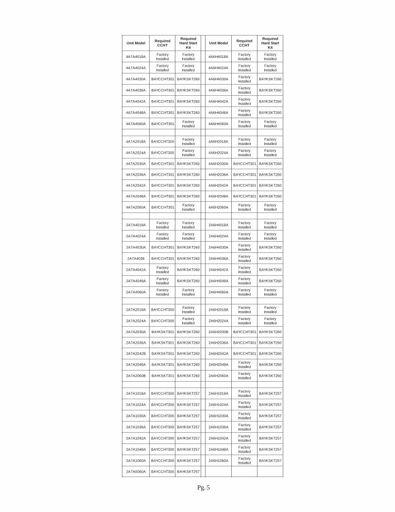
ledoMtinU deriuqeRTHCC
deriuqeRtratSdraH
tiKledoMtinU deriuqeR
THCC
deriuqeRtratSdraH
tiK
A8104A7A4 yrotcaFdellatsnI
yrotcaFdellatsnI A8104H6A4 yrotcaF
dellatsnIyrotcaFdellatsnI
A4204A7A4 yrotcaFdellatsnI
yrotcaFdellatsnI A4204H6A4 yrotcaF
dellatsnIyrotcaFdellatsnI
A0304A7A4 103THCCYAB 062TKSKYAB A0304H6A4 yrotcaFdellatsnI 062TKSKYAB
A6304A7A4 103THCCYAB 062TKSKYAB A6304H6A4 yrotcaFdellatsnI 062TKSKYAB
A2404A7A4 103THCCYAB 062TKSKYAB A2404H6A4 yrotcaFdellatsnI 062TKSKYAB
A8404A7A4 103THCCYAB 062TKSKYAB A8404H6A4 yrotcaFdellatsnI 062TKSKYAB
A0604A7A4 103THCCYAB yrotcaFdellatsnI A0604H6A4 yrotcaF
dellatsnIyrotcaFdellatsnI
A8102A7A4 003THCCYAB yrotcaFdellatsnI A8102H6A4 yrotcaF
dellatsnIyrotcaFdellatsnI
A4202A7A4 003THCCYAB yrotcaFdellatsnI A4202H6A4 yrotcaF
dellatsnIyrotcaFdellatsnI
A0302A7A4 103THCCYAB 062TKSKYAB A0302H6A4 103THCCYAB 062TKSKYAB
A6302A7A4 103THCCYAB 062TKSKYAB A6302H6A4 103THCCYAB 062TKSKYAB
A2402A7A4 103THCCYAB 062TKSKYAB A2402H6A4 103THCCYAB 062TKSKYAB
A8402A7A4 103THCCYAB 062TKSKYAB A8402H6A4 103THCCYAB 062TKSKYAB
A0602A7A4 103THCCYAB yrotcaFdellatsnI A0602H6A4 yrotcaF
dellatsnIyrotcaFdellatsnI
A8104A7A2 yrotcaFdellatsnI
yrotcaFdellatsnI A8104H6A2 yrotcaF
dellatsnIyrotcaFdellatsnI
A4204A7A2 yrotcaFdellatsnI
yrotcaFdellatsnI A4204H6A2 yrotcaF
dellatsnIyrotcaFdellatsnI
A0304A7A2 103THCCYAB 062TKSKYAB A0304H6A2 yrotcaFdellatsnI 062TKSKYAB
6304A7A2 103THCCYAB 062TKSKYAB A6304H6A2 yrotcaFdellatsnI 062TKSKYAB
A2404A7A2 yrotcaFdellatsnI 062TKSKYAB A2404H6A2 yrotcaF
dellatsnI 062TKSKYAB
A8404A7A2 yrotcaFdellatsnI 062TKSKYAB A8404H6A2 yrotcaF
dellatsnI 062TKSKYAB
A0604A7A2 yrotcaFdellatsnI
yrotcaFdellatsnI A0604H6A2 yrotcaF
dellatsnIyrotcaFdellatsnI
A8102A7A2 003THCCYAB yrotcaFdellatsnI A8102H6A2 yrotcaF
dellatsnIyrotcaFdellatsnI
A4202A7A2 003THCCYAB yrotcaFdellatsnI A4202H6A2 yrotcaF
dellatsnIyrotcaFdellatsnI
A0302A7A2 103TKSKYAB 062TKSKYAB B0302H6A2 103THCCYAB 062TKSKYAB
A6302A7A2 103TKSKYAB 062TKSKYAB A6302H6A2 103THCCYAB 062TKSKYAB
B2402A7A2 103TKSKYAB 062TKSKYAB A2402H6A2 103THCCYAB 062TKSKYAB
A8402A7A2 103TKSKYAB 062TKSKYAB A8402H6A2 yrotcaFdellatsnI 062TKSKYAB
B0602A7A2 103TKSKYAB 062TKSKYAB A0602H6A2 yrotcaFdellatsnI 062TKSKYAB
A8101A7A2 003THCCYAB 752TKSKYAB A8101H6A2 yrotcaFdellatsnI 752TKSKYAB
A4201A7A2 003THCCYAB 752TKSKYAB A4201H6A2 yrotcaFdellatsnI 752TKSKYAB
A0301A7A2 003THCCYAB 752TKSKYAB A0301H6A2 yrotcaFdellatsnI 752TKSKYAB
A6301A7A2 003THCCYAB 752TKSKYAB A6301H6A2 yrotcaFdellatsnI 752TKSKYAB
A2401A7A2 003THCCYAB 752TKSKYAB A2401H6A2 yrotcaFdellatsnI 752TKSKYAB
A8401A7A2 003THCCYAB 752TKSKYAB A8401H6A2 yrotcaFdellatsnI 752TKSKYAB
A0601A7A2 003THCCYAB 752TKSKYAB A0601H6A2 yrotcaFdellatsnI 752TKSKYAB
A0600A7A2 003THCCYAB 752TKSKYAB
Pg. 5

Typical wiring when using the evaporator defrost control (EDC) for operation as specified on page 3.
Cooling Split System and AY28X079 Evaporator Defrost Control
R
Y
G
W
W2
Red (R)
Y
Green (G)
White (W1)
White (W2)
White (W3)
Blue (B)
Orange (O)
R
Y
G
W1
X2
B
O
EDR-1
EDC
EDR
Y
Red (R)
Y
Green (G)
White (W1)
White (W2)
White (W3)
Blue (B)
EDC
Heat Pump Split System and AY28X084 Evaporator Defrost Control
2A7A / 2A7C Air Handler Thermostat
Air Handler
Pg. 6
Red
Yellow
X2
Blue
Orange
Thermostat2A6H / 2A6C
B B
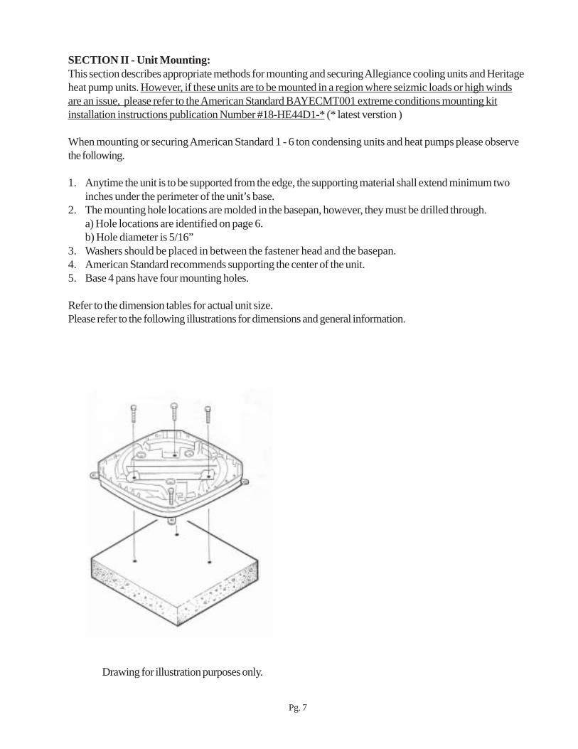
SECTION II - Unit Mounting:This section describes appropriate methods for mounting and securing Allegiance cooling units and Heritageheat pump units. However, if these units are to be mounted in a region where seizmic loads or high windsare an issue, please refer to the American Standard BAYECMT001 extreme conditions mounting kitinstallation instructions publication Number #18-HE44D1-* (* latest verstion )
When mounting or securing American Standard 1 - 6 ton condensing units and heat pumps please observethe following.
1. Anytime the unit is to be supported from the edge, the supporting material shall extend minimum twoinches under the perimeter of the unit’s base.
2. The mounting hole locations are molded in the basepan, however, they must be drilled through.a) Hole locations are identified on page 6.b) Hole diameter is 5/16”
3. Washers should be placed in between the fastener head and the basepan.4. American Standard recommends supporting the center of the unit.5. Base 4 pans have four mounting holes.
Refer to the dimension tables for actual unit size.Please refer to the following illustrations for dimensions and general information.
Drawing for illustration purposes only.
Pg. 7

BASE PAN MOUNTING HOLE LOCATIONS( location only, holes must be drilled )
support must extend 2” from the basepan perimeter
support center of unit Drill 4 places
Drill 3 places
Drill 3 places
Drill 4 places
Drill 3 places
support must extend 2” from the basepan perimeter
support center of unit
Pg. 8
If supporting the base pan from the perimeter, the support must extend under the base pan at least 2”. AmericanStandard recommends supporting the middle of the base pan with a cross member.

BASE PAN MOUNTING HOLE LOCATIONS( location only, holes must be drilled )
support must extend 2” from the basepan perimeter
If supporting the base pan from the perimeter, the support must extend under the base pan at least 2”. AmericanStandard recommends supporting the middle of the base pan with a cross member.
Pg. 9
support center of unit
Drill 4 places
Drill 4 places
support must extend 2” from the basepan perimeter
support center of unit
Drill 4 places
Drill 4 places

Section III - Minimum Operating Clearances
This section discusses applying a condensing unit / heat pump in installations where there are spaceconstraints. The reduced clearances described in this document are for operation purposes only.Local Codes prevail for servicing and sefety.
These concerns must be addressed:1. System Operation - Adequate airflow must be provided to the condensing unit / heat pump in orderto enable appropriate heat transfer. If this is accomplished, head pressure will remain within an effectiveoperating range.2. System Servicability - Proper space must be allowed for the HVAC service technician to properlymaintain the condensing unit / heat pump. Furthermore, space must be allowed for majorcomponent change out in the event of a failure. Working space is determined by the National ElectricCode3. Space Maintenance - Appropriate area must be allowed in order maintain the ground area where theunits are positioned to prohibit debris from collecting on the panels, thus further providing unobstructedairflow to the condensing unit.4. State, Local Codes, and National Codes shall prevail. Check with the local jurisdiction beforeinstallation to assure compliance.
Numerous projects require reduced clearances between outdoor units and adjacent walls, fences and otherunits. The obstruction in question is usually one of the following:
1. One or more walls of an adjacent building.2. Fences or barriers provided to reduce sound transmission or visually screen the equipment.3. Other outdoor units in a multi-unit installation.4. Overhangs5. A combination of the above.
The prime considerations involved in establishing minimum clearances are:1. Adequate airflow to the outdoor coil with minimum recirculation.2. Service access to the equipment.3. Compliance with the National Electric Code and other applicable codes.4. Design temperature - Design temperatures greater than 105F require additional consideration.
I. In order to assure that adequate airflow reaches the Allegiance 18 condensing unit, size free air passagesat 300 feet per minute maximum velocity (FPM). See condensing unit airflow performance on page 16 ofthis document; or, for the most current information, consult the unit’s product data manual.
II. The importance of providing sufficient access for maintenance and service to equipment cannot beoveremphasized. The HVAC service technician’s job may be performed with greater ease and at lower costif adequate space is allowed.
III. Knowledge of the National Electric Code and other applicable codes for the job sight location is anecessity in order to satisfy local inspectors. These codes are in place for service as well as safety.
IV. Be sure to read all provisions and footnotes contained in this document. When ambient temperaturesexceed 105F, more space may be required for minimum operating clearances.
Pg. 10

1. Installation of a single Allegiance / Heritage condensing unit / heat pump in a corner withunrestricted top clearance.A) For locations where the design ambient temperature is below 105F:
1) 1.0 feet clearance on 2 sides - If shrubbery is to be placed by the unit other side, then allow 1.0Feet minimum clearance from the unit2) Service access side minimum 3’. Consult Local, State, and National Electric Codes for minimumservice clearance.
B) For locations where the design ambient temperature exceeds 105F:1) 1.5 feet clearance on 2 walls. - If shrubbery is to be placed by the unit other side, then allow 1.0Feet minimum clearance from the unit.2) Service access side minimum 3’
C) If unit is located in such a way that service panel is facing the wall1) NEC requires minimum 3 feet between the unit and the wall a) This space may be increased to 3 1/2 feet. Consult the National Electric Code for more information regarding minimum clearances for working spaces.
2. Installation of two or more Allegiance / Heritage units where two adjacent walls form acorner and unrestricted top clearance.A) For locations where the design ambient temperature is below 105F:
1) Corner unit shall have1.5 feet clearance from side wall and 1.0 feet clearance from back wall.2) 1 feet clearance in between units, unless service panels face each other. ( if service panels face each other, this clearance may be increased to 4 feet per NEC)
B) For locations where the design ambient temperature exceeds 105F:1) 2.0 feet clearance from both walls.2) 2 feet clearance in between units, unless service panels face each other. ( if service panels face each other, this clearance may be increased to 4 feet per NEC)
C) If unit’s are located in such a way that the service panels are facing the wall1) NEC requires minimum 3 feet between the unit and the wall a) This space may be increased to 3 1/2 feet. Consult the most current edition of the National Electric Code for more information regarding minimum clearances for working spaces.
SERVICE ACCESS PANEL SIDE 3’ minimum clearance
Service Panel
-1.0’-m i n
-1.0
’-m
in-1
.0’-
min
-1.0
’-m
in
-1.0
’-m
in
-1.5’-m i n
-1.0’-m i n
-1.0’-m i n
Pg. 11
-1.0
’-m
in
3.0’ min 5 feet minimum unrestricted topclearance shall be provided.
5 feet minimum unrestricted topclearance shall be provided.

3. Single Allegiance / Heritage condensing unit / heat pump in a fenced corner withunrestricted top clearanceA) For locations where the design ambient temperature is below 105F:
1) 1.0 feet clearance from both walls.2) 1.0 feet fence clearance - openings shall be provided to allow free air passage to unit. ( Free airpassage shall be sized @ 300 FPM Velocity)3) Service access shall be 3.0 feet minimum
B) For locations where the design ambient temperature exceeds 105F:1) 1.5 feet clearance from both walls.3) 1.5 feet clearance from fence. openings shall be provided to allow free air passage to unit. ( Freeair passage shall be sized @ a maximum of 300 FPM Velocity)2) Service access shall be 3.0 feet minimum.
C) If unit is located in such a way that service panel is facing the wall1) NEC requires minimum 3 feet between the unit and the wall a) This space may be increased to 3 1/2 feet. Consult the National Electric Code for more information regarding minimum clearances for working spaces.
*Service Panel
*Service Panel
-1.0’-m i n
-1.0
’-m
in
-1.0
’-m
in
-1.0’-m i n
12341234
12341234
12121212
1212121212
1234512345
123451234512345
1212121212
12121212
-1.0
’-m
in
-3.0’-m i n
-1.0’-m i n
-3.0
’-m
in
123123123123123123123123123123123123123123123123123123123123123
SIngle Unit - Solid Fence
Solid Fence: Fence height not to exceed top of unit. Provide openings in fence that will allow maximum 300 FPM air velocity.These openings shall be located at the lower portion of the fence. If acceptable, the lower portion of the fence may be cut toprovide open bottom clearance provided that debris, grass and vegetation will not obstruct air passageway.
* If removable panels are used and acceptable to local inspection agency, the clearance to the removablepanel may be reduced to 2.0 feet
123456712345671234567
opening size @300 FPM maximumvelocity
Pg. 12
5’ minimum top clearance required.Unit shall be positioned where not affectedby water run off from roof.
123412341234123412341234123412341234123412341234123412341234123412341234123412341234
Multiple Units Solid Fence
* If removable panels are used and acceptable to local inspection agency, the clearance to theremovable panel may be reduced to 2.0 feet
12345671234567
123456123456
opening size @300 FPM maximumvelocity
SERVICE ACCESS PANEL SIDE*
-1.5
’-m
in
-1.5
’-m
in
-1.5
’-m
in
-1.5’-m i n
-1.5’-m i n
-1.5’-m i n
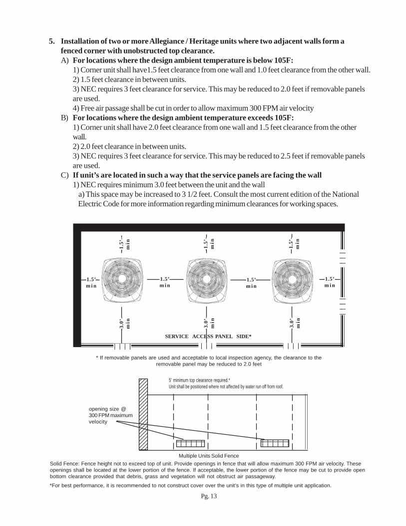
5. Installation of two or more Allegiance / Heritage units where two adjacent walls form afenced corner with unobstructed top clearance.A) For locations where the design ambient temperature is below 105F:
1) Corner unit shall have1.5 feet clearance from one wall and 1.0 feet clearance from the other wall.2) 1.5 feet clearance in between units.3) NEC requires 3 feet clearance for service. This may be reduced to 2.0 feet if removable panelsare used.4) Free air passage shall be cut in order to allow maximum 300 FPM air velocity
B) For locations where the design ambient temperature exceeds 105F:1) Corner unit shall have 2.0 feet clearance from one wall and 1.5 feet clearance from the otherwall.2) 2.0 feet clearance in between units.3) NEC requires 3 feet clearance for service. This may be reduced to 2.5 feet if removable panelsare used.
C) If unit’s are located in such a way that the service panels are facing the wall1) NEC requires minimum 3.0 feet between the unit and the wall a) This space may be increased to 3 1/2 feet. Consult the most current edition of the National Electric Code for more information regarding minimum clearances for working spaces.
Solid Fence: Fence height not to exceed top of unit. Provide openings in fence that will allow maximum 300 FPM air velocity. Theseopenings shall be located at the lower portion of the fence. If acceptable, the lower portion of the fence may be cut to provide openbottom clearance provided that debris, grass and vegetation will not obstruct air passageway.
-3.0
’-m
in
-3.0
’-m
in
-3.0
’-m
in
-1.5’-m i n
12341234
1234512345
1234512345
1212121212
12121212
Pg. 13
5’ minimum top clearance required.*Unit shall be positioned where not affected by water run off from roof.
*For best performance, it is recommended to not construct cover over the unit’s in this type of multiple unit application.

6. Installation of a single Allegiance / Heritage style condensing unit / heat pump next to onewall with unrestricted top clearance where property line space is critical.A) For locations where the design ambient temperature is below 105F:
1) 6” clearance on 1 side.2) 3’ clearance on other three sides.3) If fence or barrier is constructed around unit, 3’ clearance is required on three sides. The fence /barrier height shall not exceed the height of the unit.4) Free air passage shall be cut in order to allow maximum 300 FPM air velocity if fence / barrier isconstructed.5) Service access side minimum 3’
C) If unit is located in such a way that service panel is facing the wall1) NEC requires minimum 3 feet between the unit and the wall a) This space may be increased to 3 1/2 feet. Consult the National Electric Code for more information regarding minimum clearances for working spaces.
Service Panel
-3.0’-m i n
5 feet minimum unrestricted topclearance shall be provided.
3 feet minimum clearance on 3 sides.Unit to be positioned where notaffected by roof run off water.
Local code prevails. Unit will operate ifinstalled in this manner, however, allinstallations must meet local code.
-6.0
”m
in
Pg. 14
-3.0’-m i n
-6.0
”m
in
-3.0’-m i n
-3.0
’-m
in
123456789012345123456789012345123456789012345
123123123123123123123123123123123123
121212121212121212121212
Service Panel5 feet minimum unrestricted topclearance shall be provided.
3 feet minimum clearance on 3 sides.Unit to be positioned where notaffected by roof run off water.
Louvers / Free area shall be cut infence / barrier to provide maximum300 FPM air velocity. Lower portion offence / barrier may be undercut toallow free air passage to unit providingthat vegetation and debris will notblock air passage.
-3.0’-m i n
-3.0
’-m
in
It is recommended to allow minimum 12” clearance from any wall or surrounding shrubbery on two sides if at all possible.Clearance may be reduced to 6” on one wall only if required by code to meet required distance.

4. Installation of multiple units on a pad or rooftop with unobstructed top clearance.A) Refer to drawing for minimum clearances.
1) Do not construct cover over units in this application.B) National Electric Code requires 3 feet minimum (4 feet if certain conditions are present) clearancebetween service access panel and adjacent unit. If service access panel faces the wall, the requiredspace between the the wall and the unit shall be minimum 3 feet. (May require as much as 3 1/2 feet)C) Walls shall not be higher than top of units.D) National, State, and Local Codes must be observed.
1.0’min**
1.0’
min
**
1.0’
min
**
1.0’
min
**
1.0’min**
1.0’min**
1.5’m i n
1.5’m i n
1.5’m i n
1.5’m i n
1.5’m i n
1.5’m i n
-3.0
’-m
in
-3.0
’-m
in
3.0’
min
3.0’
min
-3.0
’-m
in3.
0’m
in
Service Access * Service Access *
Service Access * Service Access * Service Access *
* Units may be rotated, as shown on the following page, in order that service access sidesface each other provided that 3 feet minimum clearance be maintained between the units.In order to comply with NEC, this may increase to 4 feet minimum clearance.** If wall or fence is to be constructed around the entire perimeter of themechanical yard, Maintain minimum 1.5 feet clearance from the units. The fence heightshall not exceed that of the unit. It is recommended to install louvers in the fence to allowno greater than 300 feet per minute velocity. Consult the table on page 18 for unit airflow.Place louvers in the lower section of the fence by each unit in order to provide air access toeach unit located by the fence. The lower portion of the fence may also be cut in order toequal the calculated free area.
Pg. 15
Service Access *
Service Access * Service Access * Service Access *
3.0’
min
3.0’
min
3.0’
min
Clearances apply to geographicalareas where the design outdoor drybulb = 105 F or less

4. Installation of multiple units on a pad or rooftop where the top clearance is open.A) Refer to minimum clearance table in the lower corner of this page for required clearancesB) National Electric Code requires 3 feet minimum (4 feet if certain conditions are present) clearancebetween service access panel and adjacent unit. If service access panel faces the wall, the requiredspace between the wall and the unit shall be minimum 3 feet. (May require as much as 3 1/2 feet)C) Walls / Fence height shall not be higher than top of units.D) National, State, and Local Codes must be observed.
1.0’min**
1.0’
min
**
1.0’
min
**
1.0’
min
**
1.0’min**
1.0’min**
1.5’m i n
1.5’m i n
1.5’m i n
1.5’m i n
1.5’m i n
1.5’m i n
-3.0
’-m
in
-3.0
’-m
in
1.5’
min
1.5
min
-3.0
’-m
in1.
5m
in
Service Access * Service Access * Service Access *
Service Access * Service Access * Service Access *
Service Access * Service Access * Service Access *
* Units may be rotated as shown on above, in order that service access sides face each otherprovided that 3 feet minimum clearance be maintained between the units. In order tocomply with NEC, this may increase to 4 feet minimum clearance.** If wall or fence is to be constructed around the entire perimeter of the mechanical yard,Maintain minimum 1.5 feet clearance from the units. The fence height shall not exceedthat of the unit. It is recommended to install louvers in the fence to allow no greater than300 feet per minute velocity. Consult the table on page 18 for unit airflow. Place louvers inthe lower section of the fence by each unit in order to provide air access to each unitlocated by the fence. The lower portion of the fence may also be cut in order to equal thecalculated free area.
Pg. 16
Clearances apply to geographicalareas where the design outdoor drybulb = 105 F or less

66 22-3237-02
UNIT
12" MIN.
2 1/2" MIN.
UNIT
12" MIN.
UNIT UNIT
SHIELD DESIGN FORHIGHLY DIRECTIONAL WINDS
SERVICEACCESSAREASEE NOTES
SERVICEACCESSAREASEE NOTES
SHIELD DESIGNED FORNON-DIRECTIONAL WINDS
REMOVEABLE PANELOR GATEFOR SERVICE
PREVAILINGWIND DIRECTION
SHADOW BOX FENCE33% MIN. FREE AREAEACH SIDE
4" MINIMUM24" MAXIMUM
2" MINIMUM4" MAXIMUM
SOLID PANEL
Notes:• Service access working clearance (3 feet) for electrical and refrigerant components must meet NEC Article 110-16
requirements and local codes.Note:
Minimum working clearance must be in compliance with the National Electric Code. Currently,
the minimum clearance between a wood or suitable grounding material type fence requires
minimum 3 feet. If other material is used to form the windshield, the minimum space may be
increased to 3.5 feet. Please consult the 2002 or current Edition of the National Electric Code,
Article 110 for the most up to date information
D) Fence construction.1) Height shall not exceed the top of the unit.2) Free air passages shall be size at no greater than 300 FPM velocity.3) Free air passages shall be cut at the lower portion of the fence.4) Fence may also be undercut to allow free air passage provided grass, vegetation, or debris willnot obstruct the free air passage.5) Shrubbery shall not be planted within one foot of the fence.6) If removable panel is utilized, the distance from the unit’s service panel to the removable panelmay be reduced to 2.0 feet. (3.0 feet if geographical location’s design outdoor dry bulb is greaterthan 1050 F.
E) Windshields:If low ambient operation to 30F or lower is required, windshields may be required to block prevailingwinds from impacting system performance at low outdoor temperatures.
Pg. 17
1.5’ 1.5’
Shadow Box Fence shallnot exceed unit’s topheight unless lowerpotion is undercut
1.5’ 1.5’
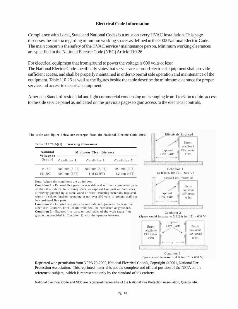
Electrical Code Information
Compliance with Local, State, and National Codes is a must on every HVAC Installation. This pagediscusses the criteria regarding minimum working spaces as defined in the 2002 National Electric Code.The main concern is the safety of the HVAC service / maintenance person. Minimum working clearancesare specified in the National Electric Code (NEC) Article 110.26
For electrical equipment that from ground to power the voltage is 600 volts or less:The National Electric Code specifically states that service area around electrical equipment shall providesufficient access, and shall be properly maintained in order to permit safe operation and maintenance of theequipment. Table 110.26 as well as the figures beside the table describe the minimum clearance for properservice and access to electrical equipment.
American Standard residential and light commercial condensing units ranging from 1 to 6 ton require accessto the side service panel as indicated on the previous pages to gain access to the electrical controls.
Condition 1(3 ft min. for 151 - 600 V)
Condition 2(Space would increase to 3 1/2 ft for 151 - 600 V)
Condition 3(Space would increase to 4 ft for 151 - 600 V)
Minimum Clear Distance
Condition 1 Condition 2 Condition 3
NominalVoltage to
Ground
0-150 900 mm (3 FT) 900 mm (3 FT) 900 mm (3FT) 151-600 900 mm (3FT) 1 M (3.5FT) 1.2 mm (4FT)
Note: Where the conditions are as followsCondition 1 - Exposed live parts on one side and no live or grounded partson the other side of the working space, or exposed live parts on both sideseffectively guarded by suitable wood or other insulating materials. Insulatedwire or insulated busbars operating at not over 300 volts to ground shall notbe considered live partsCondition 2 - Exposed live parts on one side and grounded parts on theother side. Concrete, brick, or tile walls shall be considered as grounded.Condition 3 - Exposed live parts on both sides of the work space (notguarded as provided in Condition 1) with the operator between.
Table 110.26(A)(1) Working Clearances
The table and figure below are excerpts from the National Electric Code 2002:
Pg. 18
Reprinted with permission from NFPA 70-2002, National Electrical Code®, Copyright © 2001, National FireProtection Association. This reprinted material is not the complete and official position of the NFPA on thereferenced subject, which is represented only by the standard of it’s entirety.
National Electrical Code and NEC are registered trademarks of the National Fire Protection Association, Quincy, MA.
Electricswitchboard
150V nominalor less
Effectively Insulated
Electricswitchboard
150V nominalor less
Electricswitchboard
150V nominalor less
Electricswitchboard
150V nominalor less
ExposedLive Parts
ExposedLive Parts
ExposedLive Parts
Grounded parts, concrete, etc
3’
3’
3’

Required Opening = CFM / 300 FPM (Maximum)Example:Given:Qty of 2 units in an area surrounded by a fence on two sides and solid walls on the other two sides. Unitsare 2A7A2060B1000A -Required:Determine free air opening space required in fence -Solution:4275CFM X Qty of 2 = 8550 CFM8550 CFM / 300 FPM = 28.5 square feetRound 28.5to 29 square feet of free air opening in the fence sections surrounding the units. It is recom-mended to place these opening equally on all four sides, however, if one or two of the sides are sections ofthe building structure, it is acceptable to place them on two sides.
*Table produced June 2003. For the most current information, please refer to specific equipment Product Data.
Pg. 19
elbaTwolfriAtinUroodtuOegatireH/ecnaigellA
stinUgnilooC stinUpmuPtaeH
rebmuNledoMtinU MFC rebmuNledoMtinU MFC rebmuNledoMtinU MFC rebmuNledoMtinU MFC
A8104A7A4 0012 A8104A7A2 0002 1A8104H6A4 0022 1A8104H6A2 0012
A4204A7A4 0072 A4204A7A2 0082 1A4204H6A4 0072 1A4204H6A2 5782
A0304A7A4 0013 A0304A7A2 0013 1A0304H6A4 0523 1A0304H6A2 0024
A6304A7A4 0013 A6304A7A2 0013 1A6304H6A4 0004 1A6304H6A2 0524
A2404A7A4 0044 A2404A7A2 0044 1A2404H6A4 0024 1A2404H6A2 0524
A8404A7A4 0044 A8404A7A2 0044 1A8404H6A4 0024 1A8404H6A2 0524
A0604A7A4 0044 A0604A7A2 0044 1A0604H6A4 0044 1A0604H6A2 0524
A8102A7A4 0072 A8102A7A2 0061 1A8102H6A4 0072 1A8102H6A2 0061
A4202A7A4 0072 A4202A7A2 0052 1A4202H6A4 0072 1A4202H6A2 0002
A0302A7A4 0533 A0302A7A2 0052 1A0302H6A4 0033 1B0302H6A2 0052
A6302A7A4 0523 A6302A7A2 0052 1A6302H6A4 0033 1A6302H6A2 5233
B2402A7A4 0023 B2402A7A2 0072 1A2402H6A4 0083 1A2402H6A2 5233
A8402A7A4 0043 A8402A7A2 0043 1A8402H6A4 0034 1A8402H6A2 0073
B0602A7A4 0524 B0602A7A2 5724 1A0602H6A4 0044 1A0602H6A2 0044
A8101A7A2 0541 A2401A7A2 5742 A8101H6A2 5751 A2401H6A2 5233
A4201A7A2 5741 A8401A7A2 5742 A4201H6A2 5712 A8401H6A2 0073
A0301A7A2 0552 A0601A7A2 0043 A0301H6A2 5742 A0601H6A2 0044
A6301A7A2 0052 A0600A7A2 0073 A6301H6A2 5742

Pg. 20
ledoMtinU esaB A B C ledoMtinU eziSesaB A B C
A8104A7A4 3 "4/323 "8/523 "4/392 1A8104H6A4 3 "4/323 "8/523 "4/392
A4204A7A4 3 "4/323 "8/523 "4/392 1A4204H6A4 3 "4/323 "8/523 "4/392
A0304A7A4 3 "4/323 "8/523 "4/392 1A0304H6A4 4 "8/114 "4/173 "4/143
A6304A7A4 3 "4/363 "8/523 "4/392 1A6304H6A4 4 "8/173 "4/173 "4/143
A2404A7A4 4 "8/173 "4/173 "4/143 1A2404H6A4 4 "8/114 "4/173 "4/143
A8404A7A4 4 "8/114 "4/173 "4/143 1A8404H6A4 4 "8/114 "4/173 "4/143
A0604A7A4 4 "8/114 "4/173 "4/143 1A0604H6A4 4 "8/114 "4/173 "4/143
A8102A7A4 3 "4/323 "8/523 "4/392 1A8102H6A4 3 "4/323 "8/523 "4/382
A4202A7A4 3 "4/323 "8/523 "4/392 1A4202H6A4 3 "4/323 "8/523 "4/382
A0302A7A4 3 "4/323 "8/523 "4/392 1A0302H6A4 3 "4/323 "8/523 "4/382
A6302A7A4 3 "4/323 "8/523 "4/392 1A6302H6A4 3 "4/304 "8/523 "4/382
A2402A7A4 3 "4/363 "8/523 "4/392 1A2402H6A4 3 "4/304 "8/523 "4/382
A8402A7A4 3 "4/304 "8/523 "4/392 1A8402H6A4 4 "4/323 "4/173 "4/143
A0602A7A4 4 "4/323 "4/173 "4/143 1A0602H6A4 4 "8/114 "4/173 "4/143
Allegiance / Heritage unit dimensions HFC - 410A Models

Allegiance / Heritage unit dimensionsHCFC - 22 Models
Pg. 21
ledoMtinU esaB A B C ledoMtinU eziSesaB A B C
A8104A7A2 3 "4/323 "8/523 "4/392 A8104H6A2 3 "4/323 "8/523 "4/392
A4204A7A2 3 "4/323 "8/523 "4/392 A4204H6A2 3 "4/363 "8/523 "4/392
A0304A7A2 3 "4/323 "8/523 "4/392 A0304H6A2 4 "8/133 "4/173 "4/143
A6304A7A2 3 "4/363 "8/523 "4/392 A6304H6A2 4 "8/173 "4/173 "4/143
A2404A7A2 4 "8/173 "4/173 "4/143 A2404H6A2 4 "8/114 "4/173 "4/143
A8404A7A2 4 "8/114 "4/173 "4/143 A8404H6A2 4 "8/114 "4/173 "4/143
A0604A7A2 4 "8/114 "4/173 "4/143 A0604H6A2 4 "8/114 "4/173 "4/143
A8102A7A2 2 "8/552 "2/182 "8/552 A8102H6A2 2 "8/552 "2/182 "8/552
A4202A7A2 2 "4/382 "2/182 "8/552 A4202H6A2 2 "4/382 "2/182 "8/552
A0302A7A2 2 "4/382 "2/182 "8/552 B0302H6A2 2 "4/323 "2/182 "8/552
A6302A7A2 2 "4/323 "2/182 "8/552 A6302H6A2 3 "4/323 "8/523 "4/382
B2402A7A2 3 "4/323 "8/523 "4/392 A2402H6A2 3 "4/323 "8/523 "4/382
A8402A7A2 3 "4/363 "8/523 "4/392 A8402H6A2 3 "4/363 "4/173 "4/143
B0602A7A2 4 "8/114 "4/173 "4/143 A0602H6A2 4 "8/114 "4/173 "4/143
A8101A7A2 1 "2/152 "4/391 "4/381 A8101H6A2 2 "8/552 "2/182 "8/552
A4201A7A2 1 "2/152 "4/391 "4/381 A4201H6A2 2 "8/552 "2/182 "8/552
A0301A7A2 2 "8/552 "2/182 "8/552 A0301H6A2 2 "4/382 "2/182 "8/552
A6301A7A2 2 "8/552 "2/182 "8/552 A6301H6A2 2 "4/382 "2/182 "8/552
A2401A7A2 2 "4/382 "2/182 "8/552 A2401H6A2 3 "4/323 "8/523 "4/392
A8401A7A2 2 "4/382 "2/182 "8/552 A8401H6A2 3 "4/323 "8/523 "4/392
A0601A7A2 3 "4/363 "8/523 "4/392 A0601H6A2 4 "8/133 "4/173 "4/143
A0600A7A2 3 "4/323 "8/523 "4/392

Pg. 22
NOTES

Pg. 23
NOTES
Literature Order NumberFile Number ALG-APG04-EN 08/04Supersedes ALG-APG03-EN 09/03Stocking Location
Since American Standard has a policy of continuous product improvement, it reserves theright to change design and specifications without notice.
American Standard, Inc6200 Troup HighwayTyler, Texas 75711
©2003 American Standard, Inc.