Embed Size (px)
Citation preview

https://support.industry.siemens.com/cs/ww/en/view/109486064
Application Example 04/2016
Using TIA Portal in a Virtualized Infrastructure STEP 7, WinCC and WinCC Runtime with Clients and Servers

Warranty and Liability
Virtualizing TIA Portal Entry ID: 109486064, V1.0, 04/2016 2
S
iem
ens
AG 2
016
All r
ight
s re
serv
ed
Warranty and Liability
Note The Application Examples are not binding and do not claim to be complete regarding the circuits shown, equipping and any eventuality. The Application Examples do not represent customer-specific solutions. They are only intended to provide support for typical applications. You are responsible for ensuring that the described products are used correctly. These Application Examples do not relieve you of the responsibility to use safe practices in application, installation, operation and maintenance. When using these Application Examples, you recognize that we cannot be made liable for any damage/claims beyond the liability clause described. We reserve the right to make changes to these Application Examples at any time without prior notice. If there are any deviations between the recommendations provided in this Application Example and other Siemens publications – e.g. Catalogs – the contents of the other documents shall have priority.
We do not accept any liability for the information contained in this document. Any claims against us – based on whatever legal reason – resulting from the use of the examples, information, programs, engineering and performance data etc., described in this application example shall be excluded. Such an exclusion shall not apply in the case of mandatory liability, e.g. under the German Product Liability Act (“Produkthaftungsgesetz”), in case of intent, gross negligence, or injury of life, body or health, guarantee for the quality of a product, fraudulent concealment of a deficiency or breach of fundamental contractual obligations (“wesentliche Vertragspflichten”). The damages for a breach of a substantial contractual obligation are, however, limited to the foreseeable damage, typical for the type of contract, except in the event of intent or gross negligence or injury to life, body or health. The above provisions do not imply a change of the burden of proof to your detriment. Any form of duplication or distribution of these Application Examples or excerpts hereof is prohibited without the expressed consent of Siemens AG.
Security informa-
tion
Siemens provides products and solutions with industrial security functions that support the secure operation of plants, systems, machines and networks. To protect plants, systems, machines and networks against cyber threats, it is necessary to implement (and continuously maintain) a holistic, state-of-the-art industrial security concept. Products and solutions from Siemens are only one part of such a concept. The customer is responsible for preventing unauthorized access to the customer’s plants, systems, machines and networks. Systems, machines and components should be connected to the company network or the Internet only if and to the extent necessary and if appropriate protective action (e.g., use of firewalls and network segmentation) was taken. In addition, Siemens’ recommendations regarding appropriate protective action should be followed. For more information about industrial security, visit http://www.siemens.com/industrialsecurity. Siemens’ products and solutions undergo continuous development to make them even more secure. Siemens strongly recommends to perform updates as they become available and use only the latest product versions. Using versions that are out of date or no longer supported can increase the risk of cyber threats. To stay informed about product updates as they occur, subscribe to the Siemens Industrial Security RSS feed at http://www.siemens.com/industrialsecurity.

Table of Contents
Virtualizing TIA Portal Entry ID: 109486064, V1.0, 04/2016 3
S
iem
ens
AG 2
016
All r
ight
s re
serv
ed
Table of Contents Warranty and Liability ................................................................................................. 2
1 Task ..................................................................................................................... 4
1.1 Overview............................................................................................... 4 1.2 Requirements ....................................................................................... 5
2 Solution............................................................................................................... 6
2.1 Overview............................................................................................... 6 2.2 Hardware and software components ................................................... 8 2.2.1 Scope ................................................................................................... 8 2.2.2 Validity .................................................................................................. 8 2.2.3 Components used ................................................................................ 8 2.2.4 TIA Portal project ................................................................................ 10
3 Configuration and Project Engineering ......................................................... 12
3.1 Procedure ........................................................................................... 12 3.2 Virtualization infrastructure ................................................................. 13 3.2.1 Selecting the suitable virtualization hardware .................................... 13 3.2.2 Architecture, installation and configuration of the virtualization
hardware............................................................................................. 13 3.2.3 Operating the virtual infrastructure ..................................................... 15 3.2.4 Storage system .................................................................................. 15 3.2.5 Virtual network .................................................................................... 17 3.3 vSphere configuration example .......................................................... 21 3.3.1 Cluster Settings .................................................................................. 21 3.3.2 vMotion and Storage vMotion ............................................................ 34 3.3.3 SDRS (Storage DRS) ......................................................................... 35 3.3.4 FT (Fault Tolerance) ........................................................................... 39 3.4 Creating virtual machines for the TIA Portal ...................................... 40 3.4.1 Introduction ......................................................................................... 40 3.4.2 Wizard to create a new virtual machine ............................................. 40 3.4.3 VMware Converter ............................................................................. 41 3.4.4 VMware Workstation .......................................................................... 42 3.4.5 Creating a virtual machine based on a Windows template ................ 42 3.4.6 Configuring the individual virtual machines ........................................ 47 3.4.7 Exchanging data with a virtual machine (e.g. to install SIMATIC
SW) ..................................................................................................... 52 3.4.8 Time synchronization ......................................................................... 53 3.4.9 Installing SIMATIC software ............................................................... 54
4 Further Notes, Tips and Tricks ....................................................................... 55
4.1 General recommendations ................................................................. 55 4.2 Important security settings ................................................................. 56 4.3 Compilation times ............................................................................... 57 4.4 Troubleshooting and performance ..................................................... 58 4.4.1 Performance monitoring with vSphere Client or Web Client .............. 58 4.4.2 ESXTOP ............................................................................................. 59 4.4.3 Examples ............................................................................................ 62
5 Related Literature ............................................................................................ 67
6 List of Abbreviations ....................................................................................... 68
7 History............................................................................................................... 68

1 Task 1.1 Overview
Virtualizing TIA Portal Entry ID: 109486064, V1.0, 04/2016 4
S
iem
ens
AG 2
016
All r
ight
s re
serv
ed
1 Task 1.1 Overview
Introduction Virtualizing applications and servers is well established in information technology. The advantages of virtualization can also be used in automation technology. This application example shows the options these advantages bring. The application example does not discuss the virtualization of a single workstation. It shows the virtualization of an entire infrastructure with the following components: • Engineering stations
– WinCC (TIA Portal) – STEP 7 (TIA Portal)
• WinCC Runtimes – WinCC Runtime Professional Server – WinCC Runtime Professional Client
Overview of the automation task The figure below provides an overview of the automation task. Figure 1-1 TIA Portal in a virtualized infrastructure
WinCCServer
ES Stations
Client1
Virtual Environment
S7-1500
Client2 Client3
WinCC STEP 7
Process bus
Terminal bus
Virtualized infrastructure

1 Task 1.2 Requirements
Virtualizing TIA Portal Entry ID: 109486064, V1.0, 04/2016 5
S
iem
ens
AG 2
016
All r
ight
s re
serv
ed
1.2 Requirements
Additional virtualized applications In addition to the TIA Portal other applications should be virtualized. Respectively the TIA Portal automation software should be added to an existing virtualization cluster.
Access to hardware • A program download from the virtualized STEP 7 PC to a controller should be
possible. • The virtualized WinCC server should have read/write access to tags of a
controller.
Operation of the running machine
• Operation with WinCC Runtime Professional Client. • Engineering with STEP 7 (TIA Portal).

2 Solution 2.1 Overview
Virtualizing TIA Portal Entry ID: 109486064, V1.0, 04/2016 6
S
iem
ens
AG 2
016
All r
ight
s re
serv
ed
2 Solution 2.1 Overview
A VMware cluster based on vSphere 5.5 is used to solve this task. It consists of: • Four ESXi hosts • vCenter Server as the central management component • Two storage systems
Note The task can also be solved with just a single host if this host provides enough resources.
The individual virtual machines are operated through remote access.
Diagrammatic representation The diagrammatic representation below shows the most important components of the solution: Figure 2-1 Architecture of the hardware used
Vmware vCenter Server
VM
Vmware vSphere
VMVM VM VM
Vmware vSphere
VMVM VM VM
Vmware vSphere
VMVM VM VM
Vmware vSphere
VMVM VM
Host 21 Host 31 Host 51 Host 61
SAN 1 SAN 2
NOTE The numbering of the hosts is an example. You are free to give your own names or numbers (like 1-4).

2 Solution 2.1 Overview
Virtualizing TIA Portal Entry ID: 109486064, V1.0, 04/2016 7
S
iem
ens
AG 2
016
All r
ight
s re
serv
ed
Advantages The solution presented here offers the following advantages: • Improved use of existing virtualized infrastructure systems. • Easily expandable. • Independent of the hardware used (hosts).
Scope This application does not include a description of • the basics of virtualization. • setting up a cluster environment with VMware vSphere. • setting up the remote connection/software for running the virtualized machines.
Required knowledge Basic knowledge of virtualization using VMware is required. In particular, knowledge of installing and configuring ESXi hosts and, where needed, vSphere vCenter Server for using cluster functionalities. Basic knowledge of remote connections.
2 Solution 2.2 Hardware and software components
Virtualizing TIA Portal Entry ID: 109486064, V1.0, 04/2016 8
S
iem
ens
AG 2
016
All r
ight
s re
serv
ed
2.2 Hardware and software components
2.2.1 Scope
The following example focuses on the use of VMware ESXi and vCenter Server, therefore on VMware vSphere. Workstation or Player will not be discussed as they are not released for productive operation.
2.2.2 Validity
This document is valid for: • STEP 7 Professional V13 SP1 • WinCC Runtime Professional V13 SP1 • VMware ESXi V5.5 • VMware vSphere V5.5
2.2.3 Components used
This application was created with the following components:
Software for the use of virtualization Virtualization software • VMware vSphere Client/vSphere Web Client • VMware vSphere Server ESXi • VMware vCenter Server
Note Depending on the VMware license used, certain VMware functionalities described below may not be available in your environment.
Recommended functions configured in this example: • DRS (Distributed Resource Scheduler) • SDRS (Storage DRS) • HA (High Availability) • vDS (vSphere Distributed Switch) • DPM (Distributed Power Management) • vSphere Web Client • vRealize Operations Manager (only to determine IOPS/load)

2 Solution 2.2 Hardware and software components
Virtualizing TIA Portal Entry ID: 109486064, V1.0, 04/2016 9
S
iem
ens
AG 2
016
All r
ight
s re
serv
ed
Hardware components Table 2-1
Component No. Article number
SIMATIC S7-1500 CPU 1516F-3PN/DP 1 6ES7 516-3FN00-0AB0
Software components Table 2-2 Engineering station
Component No. Article number
SIMATIC WinCC Professional max. PowerTags V13 SP1 1 6AV2103-0XA03-0AA5
SIMATIC STEP 7 Professional V13 Floating License 1 6ES7822-1AA03-0YA5 STEP 7 Safety Advanced V13 SP1 1 6ES7833-1FA13-0YA5 Windows 7 Professional SP1 (64-bit) 1
Table 2-3 WinCC server
Component No. Article number
SIMATIC WinCC Runtime Professional 153600 PowerTags V13 SP1
1 6AV2105-0RA03-0AA0
SIMATIC WinCC Logging for Runtime Professional 5000 LoggingTags
1 6AV2107-0GD00-0BB0
SIMATIC WinCC Recipes for Runtime Professional 1 6AV2107-0JB00-0BB0 SIMATIC WinCC Server for Runtime Professional 1 6AV2107-0EB00-0BB0
Microsoft Windows Server 2012 R2 Standard Edition (64-bit)
1
Table 2-4 WinCC client
Component No. Article number
SIMATIC WinCC Client for Runtime Professional V13 SP1
3 6AV2107-0DB03-0AA0
Windows 7 Professional SP1 (64-bit) 3

2 Solution 2.2 Hardware and software components
Virtualizing TIA Portal Entry ID: 109486064, V1.0, 04/2016 10
S
iem
ens
AG 2
016
All r
ight
s re
serv
ed
2.2.4 TIA Portal project
Realistic conditions The application example is based on a sample project. It consists of a STEP 7 project and a WinCC project. • STEP 7 project
The control project provides process tags for WinCC. • WinCC project
The WinCC project generates a realistic load for the virtualized machines. This allows you to make comparisons with real applications.
Sample project Each project implemented using WinCC is different and has different quantity frameworks. The following quantity framework is the basis of this document. The project serves as a reference regarding the hardware used, the number of virtual machines and the configuration of the virtual machines.
WinCC quantity framework/project Table 2-3
Component Details
CPU used 1x S7-1516 firmware V1.8.3 Number of WinCC V13 SP1 Professional clients
3
Number of external S7 tags 103548 Trend archiving 1000 Int / second
1000 Byte / second 1000 Real / second 1000 Bool / 500 milliseconds
Alarm archiving 10 discrete alarms / second User Archive 12 data records, each with 4 integers at a
5-second interval, writing Screens 29 screens with: Trend view, alarm view,
recipe view, screen windows, animated objects, VBS scripts

2 Solution 2.2 Hardware and software components
Virtualizing TIA Portal Entry ID: 109486064, V1.0, 04/2016 11
S
iem
ens
AG 2
016
All r
ight
s re
serv
ed
WinCC screens To generate a certain load, the following static screen will be displayed on the WinCC Clients in this project. The screen consists of a total of 1000 objects. The objects are divided into 500 I/O fields and 500 rectangles. All objects are connected to integer tags on the controller. Every second, they increase their value by one. To generate a graphical load, the rectangles change their color every 10 values. The design animation is used for this purpose. Figure 2-2, Configured load screen – changes in color for different process values
Figure 2-3, Configuration in WinCC
1 object
I/O field
Rectangle

3 Configuration and Project Engineering 3.1 Procedure
Virtualizing TIA Portal Entry ID: 109486064, V1.0, 04/2016 12
S
iem
ens
AG 2
016
All r
ight
s re
serv
ed
3 Configuration and Project Engineering 3.1 Procedure
The following steps are necessary to virtualize the project described above: 1. Virtualization infrastructure
Create your virtualization infrastructure based on VMware vSphere, consisting of
a. one or more independent ESXi hosts or b. a cluster managed by vCenter Server.
2. Creating virtual machines for TIA Portal
Create the following virtual machines (VMs) for your TIA project: Engineering station (ES) WinCC server Three WinCC clients
3. Operating the virtual machines
Customize the virtual machines in order to use the respective VMware vSphere functions.
4. Other notes, tips and tricks Optimize the individual virtual machines in terms of security and performance and diagnose problems that may arise.
The following pages explain items 1 through 4. For 1, the architecture used is briefly outlined. For detailed descriptions of setting up and running an ESXi host or vCenter, please refer to VMware.

3 Configuration and Project Engineering 3.2 Virtualization infrastructure
Virtualizing TIA Portal Entry ID: 109486064, V1.0, 04/2016 13
S
iem
ens
AG 2
016
All r
ight
s re
serv
ed
3.2 Virtualization infrastructure
3.2.1 Selecting the suitable virtualization hardware
General hardware compatibility Each ESXi host and its components must be listed in the VMware HCL (Hardware Compatibility List) for the respective ESXi version and license. For more information, please use the following link: https://www.vmware.com/resources/compatibility/search.php \3\
Computing power depends on the virtualized configuration The required hardware regarding computing power, storage capacity, main memory, etc. depends on the TIA Portal project. This document uses a specific example to provide appropriate decision-making aids. (See chapter “2.2.4 TIA Portal project”.)
3.2.2 Architecture, installation and configuration of the virtualization hardware
This example combines four ESXi hosts to form a single cluster. Many of the characteristics described in the following can also be used with one or more independent ESXi hosts without cluster functionality.
Architecture Figure 3-1 Architecture of the hardware used
Vmware vCenter Server
VM
Vmware vSphere
VMVM VM VM
Vmware vSphere
VMVM VM VM
Vmware vSphere
VMVM VM VM
Vmware vSphere
VMVM VM
Host 21 Host 31 Host 51 Host 61
SAN 1 SAN 2
The following table shows the servers used and their performance features.

3 Configuration and Project Engineering 3.2 Virtualization infrastructure
Virtualizing TIA Portal Entry ID: 109486064, V1.0, 04/2016 14
S
iem
ens
AG 2
016
All r
ight
s re
serv
ed
Table 3-1 Hosts and performance features
Host name Processor type CPU cores Main memory in GB
21 Intel Xeon E5645 @ 2.4 GHz 12 96 31 Intel Xeon E5645 @ 2.4 GHz 12 96 51 Intel Xeon E5-2680 v3 @ 2.5
GHz 24 256
61 Intel Xeon E7540 @ 2.0 GHz 24 384
The application example is based on this existing infrastructure and demonstrates which steps are necessary in order to use virtual machines with TIA Portal software.
Configuration For the configuration and installation of such a vSphere infrastructure, please refer to the appropriate VMware documents.
Note When configuring the options to be used, follow the VMware guides (e.g., “vSphere Installation and Setup Guide”).
For related information, please use the following link. (https://www.vmware.com/support/pubs/) \4\
This application example provides detailed descriptions of the most important aspects of configuring individual components and functions in interaction with TIA Portal. In particular, the following requirements must be met: • One or more ESXi hosts have been installed and configured. • Storage system with a suitable configuration (RAID) (hosts
connected/integrated). • Creation/configuration of a virtual switch (physical network adapters
connected). • Optional: vCenter Server with the following correctly configured functions:
– HA (High Availability) – DRS (Distributed Resource Scheduler) – DPM (Distributed Power Management) – vSphere Web Client – vDS (vSphere Distributed Switch)

3 Configuration and Project Engineering 3.2 Virtualization infrastructure
Virtualizing TIA Portal Entry ID: 109486064, V1.0, 04/2016 15
S
iem
ens
AG 2
016
All r
ight
s re
serv
ed
3.2.3 Operating the virtual infrastructure
After successful installation and basic configuration of an ESXi host, this host is configured using vSphere Client. If a vSphere vCenter Server has been set up, the vSphere Web Client can also be used. The Web Client provides additional functionalities that were only introduced with the latest versions of VMware vSphere. Where possible, this document always shows both client variants. Both can equally be used to implement the described reference architecture.
3.2.4 Storage system
The subordinate storage system is a core element within a virtualized infrastructure. To use functions such as HA , the virtual machines must be located on a storage system that offers the following: • All hosts of the cluster can access it. • The performance of the hard drives or the RAID configuration can meet all
requirements of the active virtual machines. This also applies to a single ESXi host.
This specific example uses the following storage system structure: • Two separate systems, SAN1 and SAN2. • Connected via HBAs (host bus adapters) using optical fiber cables. The
speeds are 4 GB/s or 8 GB/s. Basically, each technology supported by VMware can be used (iSCSI, NFS or FC) as it is transparent to the virtual machines. What is decisive is the provided datastore size and, in particular, its performance. Due to the shared use, it must be ensured that the IOPS (Input/Output Operations Per Second) requirements of each single machine can be met. If this is not possible, the requests enter a queue and the latencies increase, which manifests itself in a degraded performance within the virtual machine that finally can no longer be operated. See also chapter 4.4 Troubleshooting and performance. The following chapter, IOPS, lists the measured values. They serve as a reference for the required performance.
Note For increased resilience against failure, redundant connection of the storage systems is recommended. Each system is connected to each host via two independent paths.

3 Configuration and Project Engineering 3.2 Virtualization infrastructure
Virtualizing TIA Portal Entry ID: 109486064, V1.0, 04/2016 16
S
iem
ens
AG 2
016
All r
ight
s re
serv
ed
IOPS The storage system is a key component and must be able to meet the requirements of the virtual machines accessing it. In particular, the IOPS of the individual virtual machines need to be considered. The following figure shows the measured values for the individual virtual machines for 14 days. They were measured using vRealize Operations Manager (a paid VMware software option):
NOTE The example project from chapter 2.2.4 was the basis for the following values. In this project a single PLC connection is used. No interaction to the WinCC Clients was done, no screens were changed and there was no reboot or maintenance during the measurement.
The measuring values are lower than expect in real.
Figure 3-2 IOPS measured over a period of 14 days
As can be seen in Figure 3-2, the WinCC server, on average, requires roughly 47 write I/Os and the engineering station requires almost 9 read I/Os. The clients require approx. 7.5 write I/Os. For the project used, this results in the following average total requirement: • Approx. 10 read I/Os and • approx. 72.5 write I/Os.

3 Configuration and Project Engineering 3.2 Virtualization infrastructure
Virtualizing TIA Portal Entry ID: 109486064, V1.0, 04/2016 17
S
iem
ens
AG 2
016
All r
ight
s re
serv
ed
Figure 3-3 Stress measured over a period of 14 days
Figure 3-3 shows the recommendations with the set values. Three vCPUs are recommended for the engineering station as high CPU load occurs during the compilation processes, i.e., repeated peaks occur. As these are only temporary peaks, two vCPUs are sufficient. Regarding their configuration, all other machines match the recommendations.
3.2.5 Virtual network
Like physical computers, virtual machines, too, must be connected to a switch. This enables communication between the virtual machines and the automation components, i.e., the controllers. Connect the virtual network adapters to a virtual switch or port group of a virtual switch. See Figure 3-4 Port configuration overview Figure 3-4 Port configuration overview
Two options are available: 5. vSS (vSphere Standard Switch) and 6. vDS (vSphere Distributed Switch)

3 Configuration and Project Engineering 3.2 Virtualization infrastructure
Virtualizing TIA Portal Entry ID: 109486064, V1.0, 04/2016 18
S
iem
ens
AG 2
016
All r
ight
s re
serv
ed
vSphere Standard Switch vSS is available to each ESXi host, regardless of the license used. The configuration is performed for each host.
Note On each host, assign the same name to the port groups. This allows you to run the virtual machines on different hosts.
vSphere Distributed Switch The vDS is available depending on the vSphere license used. The advantage is the centralized configuration of the switch, which is then automatically distributed to all hosts. This avoids typing errors when entering the port groups and saves time when configuring and customizing. The vSphere Distributed Switch is described below. Create two port groups: • One for the plant bus and • one for the terminal bus. The assignment to the respective port groups is made via the settings of the individual virtual machines per network adapter. The configuration of the WinCC server assigned to one of the two port groups with one network adapter each is shown as an example. Figure 3-5 Configuration of the WinCC server in the standard vSphere Client

3 Configuration and Project Engineering 3.2 Virtualization infrastructure
Virtualizing TIA Portal Entry ID: 109486064, V1.0, 04/2016 19
S
iem
ens
AG 2
016
All r
ight
s re
serv
ed
Figure 3-6 Configuration of the WinCC server in the vSphere Web Client
Note Depending on the network structure, two Distributed Switches (vDS) may be necessary. The appropriate physical network adapters of the hosts are assigned to them. This is used for separate access to the different network segments and other switches and components.
Consult a network administrator on large network or on complex configurations.

3 Configuration and Project Engineering 3.2 Virtualization infrastructure
Virtualizing TIA Portal Entry ID: 109486064, V1.0, 04/2016 20
S
iem
ens
AG 2
016
All r
ight
s re
serv
ed
Connection and reachability of the S7 controller If your S7 controllers are connected to the Ethernet port of “Network adapter 1”, they can be reached via the virtual machines. This requires that the virtualized “dvPlantbus” be made available to the virtual machines. Figure 3-7 Connection of the S7 controller
VMVM VM
Vmware vSphere Host
VM
Virtual Switch
vNIC
vNIC
vNIC
vNIC
NIC
NIC
S7-1500ScalanceSwitch
1
2
1
2
Network
Virtual Network Interface
Physical Network Interface

3 Configuration and Project Engineering 3.3 vSphere configuration example
Virtualizing TIA Portal Entry ID: 109486064, V1.0, 04/2016 21
S
iem
ens
AG 2
016
All r
ight
s re
serv
ed
3.3 vSphere configuration example
Depending on the license used, the functions shown in the following sections are provided by VMware within a cluster. For the correct configuration, please refer to the appropriate VMware documentation. For related information, please use the following link. https://www.vmware.com/support/pubs/ \4\. The individual sections below show the parameterization used for this application example.
3.3.1 Cluster Settings
HA (High Availability) vSphere HA minimizes unplanned downtime: • In the event of a server failure, vSphere HA restarts virtual machines on other
hosts in the cluster. • vSphere HA continuously monitors the operating system of the virtual machine
and resets the machine if an error (e.g., a blue screen) is detected. • vSphere HA restarts virtual machines on other hosts if problems regarding
access to their datastore are detected. To use the function, vSphere HA must be enabled for the cluster and the VMware requirements must be met.

3 Configuration and Project Engineering 3.3 vSphere configuration example
Virtualizing TIA Portal Entry ID: 109486064, V1.0, 04/2016 22
S
iem
ens
AG 2
016
All r
ight
s re
serv
ed
Perform the following steps in the vSphere Client: Table 3-2
No. Action
1. Open the Cluster Settings dialog box
2. In the Cluster Settings, enable HA
3. Host Monitoring Enable host monitoring

3 Configuration and Project Engineering 3.3 vSphere configuration example
Virtualizing TIA Portal Entry ID: 109486064, V1.0, 04/2016 23
S
iem
ens
AG 2
016
All r
ight
s re
serv
ed
No. Action
4. Virtual Machine Options Keep the default values for “restart priority” and “host isolation response” for virtual machines. Optional: Change the “restart priority” for the virtual machine of the WinCC server to High. If multiple virtual machines have to be restarted, this virtual machine is assigned a higher priority.
5. VM Monitoring Set VM Monitoring to “VM Monitoring Only”.
6. Datastore Heartbeating Select the “Select any of the cluster datastores” option for datastore monitoring.

3 Configuration and Project Engineering 3.3 vSphere configuration example
Virtualizing TIA Portal Entry ID: 109486064, V1.0, 04/2016 24
S
iem
ens
AG 2
016
All r
ight
s re
serv
ed
Alternatively, you can perform these steps in the vSphere Web Client: Table 3-3
No. Action
1. Open the Cluster Settings dialog box

3 Configuration and Project Engineering 3.3 vSphere configuration example
Virtualizing TIA Portal Entry ID: 109486064, V1.0, 04/2016 25
S
iem
ens
AG 2
016
All r
ight
s re
serv
ed
No. Action
2. Configuration of vSphere HA • In the Cluster Settings, enable HA • Enable host monitoring • Select the “VM Monitoring Only” option
3. Datastore for Heartbeating Select the “Automatically select datastores accessible from the host” option for datastore monitoring.

3 Configuration and Project Engineering 3.3 vSphere configuration example
Virtualizing TIA Portal Entry ID: 109486064, V1.0, 04/2016 26
S
iem
ens
AG 2
016
All r
ight
s re
serv
ed
No. Action
4. VM Overrides Optional: Change the VM restart priority for the WinCC server to High. If multiple virtual machines have to be restarted, it is assigned a higher priority.
NOTICE HA does not protect against loss of data, it only reduces downtime.
In the event of a failure and automatic restart, data can be lost or starting the operating system can fail, for example, due to a corrupt file system.
The risks caused by a failure do not differ from physical computers.
Note To avoid loss of data, we recommend using the redundancy solution from Siemens.
Do not run the two redundant partners on the same ESXi host. For this purpose, VM-VM anti-affinity rules can be set up. They prevent running virtual machines on the same host. For details, see anti-affinity rules.
Note Furthermore, HA cannot be used if hardware was integrated into a virtual machine using the pass-through mechanism. When restarting the virtual machine on a different host, the hardware is no longer available.
For more information and a detailed description of how to correctly configure vSphere HA, please refer to the VMware documentation: “vSphere Availability Guide”. For related information, please use the following link. https://www.vmware.com/support/pubs/ \4\

3 Configuration and Project Engineering 3.3 vSphere configuration example
Virtualizing TIA Portal Entry ID: 109486064, V1.0, 04/2016 27
S
iem
ens
AG 2
016
All r
ight
s re
serv
ed
DRS (Distributed Resource Scheduler) DRS summarizes the resources of a cluster and decides, e.g. when turning on a VM, on which host it runs.
To configure DRS, perform the following steps: Table 3-4
No. Action
1. In the Cluster Settings, enable DRS
2. Activate „Partially automated“
Note Your virtual machine is not moving during operation with this setting. Only at starting your virtual machine the host is selected by automatic.

3 Configuration and Project Engineering 3.3 vSphere configuration example
Virtualizing TIA Portal Entry ID: 109486064, V1.0, 04/2016 28
S
iem
ens
AG 2
016
All r
ight
s re
serv
ed
No. Action
3. Resource pool • Create a resource pool • Name it, for example, DRP_TIA • You can make custom settings for each resource pool, for example reserve RAM or CPU
resources. Do not change the default settings • Add your virtual machine to this resource pool.
Alternatively, you can perform these steps in the vSphere Web Client:
No. Action
1. In the Cluster Settings, enable DRS
2. Activate „Partially automated“
Note Your virtual machine is not moving during operation with this setting. Only at starting your virtual machine the host is selected by automatic.

3 Configuration and Project Engineering 3.3 vSphere configuration example
Virtualizing TIA Portal Entry ID: 109486064, V1.0, 04/2016 29
S
iem
ens
AG 2
016
All r
ight
s re
serv
ed
No. Action
3. Resource pool • Create a resource pool • Name it, for example, DRP_TIA • You can make custom settings for each resource pool, for example reserve RAM or CPU
resources. Do not change the default settings • Add your virtual machine to this resource pool.
DPM (Distributed Power Management) Within a cluster, DPM can be used to automatically move virtual machines between hosts and therefore turn off hosts that are not needed. This saves power. Turn off DPM for all hosts running virtual machines with SIMATIC software. Moving virtual machines while SIMATIC software is active is not supported. Figure 3-8 DPM configuration in the vSphere Client
Figure 3-9 DPM configuration in the vSphere Web Client

3 Configuration and Project Engineering 3.3 vSphere configuration example
Virtualizing TIA Portal Entry ID: 109486064, V1.0, 04/2016 30
S
iem
ens
AG 2
016
All r
ight
s re
serv
ed
Using affinity and anti-affinity rules Within a vSphere cluster, you can define rules to ensure that certain virtual machines always run on the same host or on different hosts. If you are using a redundant WinCC server pair, make sure that both machines run on different hosts. Figure 3-10, distribution of redundant WinCC Servers
VM
Vmware vSphere
VM
Vmware vSphere Vmware vSphere
1 2
1 Redundant WinCC Server - Master
2 Redundant WinCC Server - Slave
Host A Host B Host C
If the host is down, the virtual machine of the redundant server will be restarted at another host. Figure 3-11, distribution of redundant WinCC Servers
VM
Vmware vSphere
VM
Vmware vSphere Vmware vSphere
21
1 Redundant WinCC Server - Master
2 Redundant WinCC Server - Slave
Host A Host B Host C

3 Configuration and Project Engineering 3.3 vSphere configuration example
Virtualizing TIA Portal Entry ID: 109486064, V1.0, 04/2016 31
S
iem
ens
AG 2
016
All r
ight
s re
serv
ed
Special case, only one Host is still running at HA Clusters All hosts are down but one is running, the virtual machine (from the down host) is restarted at this least host. Both the Master and the Slave are running at the same host. If the hosts came back, a redundant Server has to be restarted manually. The virtual machine will be started at the other host. Both servers are running at different host due to the affinity and anti-affinity rules. Figure 3-12, distribution of redundant WinCC Servers
VM
Vmware vSphere
VM
Vmware vSphere
21
1 Redundant WinCC Server - Master
2 Redundant WinCC Server - Slave
Host A Host B
t1
VM
Vmware vSphere
VM
Vmware vSphere
21
Host A Host B
t2
VM
Vmware vSphere
VM
Vmware vSphere
2 1
Host A Host B
t3

3 Configuration and Project Engineering 3.3 vSphere configuration example
Virtualizing TIA Portal Entry ID: 109486064, V1.0, 04/2016 32
S
iem
ens
AG 2
016
All r
ight
s re
serv
ed
To do this, perform the following steps:
Table 3-5
No. Action
1. Open the Cluster Settings dialog box (see HA (High Availability)) 2. Create a rule
• In the DRS settings, select the Rules option • Add a new rule and name it, for example, WinCC_Redundancy • Select the “Separate Virtual Machines” option and add the two WinCC servers

3 Configuration and Project Engineering 3.3 vSphere configuration example
Virtualizing TIA Portal Entry ID: 109486064, V1.0, 04/2016 33
S
iem
ens
AG 2
016
All r
ight
s re
serv
ed
Alternatively, you can perform these steps in the vSphere Web Client:
No. Action
1. Open the Cluster Settings dialog box (see HA (High Availability))
2. Create a rule • Select the VM/Host Rules item • Add a new rule and name it, for example, WinCC_Redundancy • Select the “Separate Virtual Machines” option and add the two WinCC servers

3 Configuration and Project Engineering 3.3 vSphere configuration example
Virtualizing TIA Portal Entry ID: 109486064, V1.0, 04/2016 34
S
iem
ens
AG 2
016
All r
ight
s re
serv
ed
3.3.2 vMotion and Storage vMotion
vMotion and Storage vMotion are two technologies that allow the live migration of running virtual machines.
vMotion vMotion allows the migration of the running virtual machine between the individual hosts of the cluster. The running virtual machine is relocated from one host to another.
Storage vMotion Storage vMotion allows the migration of the hard disk files of running virtual machines between storage arrays. The vmdk files are migrated from one datastore to another.
Note Storage vMotion also allows you to change the disk format. For example, you can change a thin-provisioned hard disk file to thick-provisioned.
NOTICE Do not use vMotion and Storage vMotion when SIMATIC software is active.
To avoid loss of data, use this option only when all SIMATIC software is inactive.

3 Configuration and Project Engineering 3.3 vSphere configuration example
Virtualizing TIA Portal Entry ID: 109486064, V1.0, 04/2016 35
S
iem
ens
AG 2
016
All r
ight
s re
serv
ed
3.3.3 SDRS (Storage DRS)
Storage DRS enables moving virtual machines automatically within a datastore cluster. A datastore cluster consists of individual datastores. Perform the following steps in order to use datastore clusters.
Table 3-6
No. Action
1. Open the settings of the datastore cluster
2. Turn on storage DRS

3 Configuration and Project Engineering 3.3 vSphere configuration example
Virtualizing TIA Portal Entry ID: 109486064, V1.0, 04/2016 36
S
iem
ens
AG 2
016
All r
ight
s re
serv
ed
No. Action
3. Configuration If you enable this functionality and use SDRS, assure one of the following two options for the virtual machine with SIMATIC SW: • The cluster is in manual mode. No virtual machine is migrated automatically.
• If the option "fully automated" is selected, the virtual machines with SIMATIC software
have to be excluded from this automatism.

3 Configuration and Project Engineering 3.3 vSphere configuration example
Virtualizing TIA Portal Entry ID: 109486064, V1.0, 04/2016 37
S
iem
ens
AG 2
016
All r
ight
s re
serv
ed
Alternatively, you can perform these steps in the vSphere Web Client:
No. Action
1. Open the settings of the datastore cluster
2. Turn on storage DRS

3 Configuration and Project Engineering 3.3 vSphere configuration example
Virtualizing TIA Portal Entry ID: 109486064, V1.0, 04/2016 38
S
iem
ens
AG 2
016
All r
ight
s re
serv
ed
No. Action
3. Configuration If you enable this functionality and use SDRS, assure one of the following two options for the automation of virtual machines: • The cluster is in manual mode. No virtual machine is migrated automatically.
• If the option "fully automated" is selected, the virtual machines with SIMATIC software
have to be excluded from this automatism.
NOTICE Do not move virtual machines with active SIMATIC software. This applies to vMotion and storage vMotion processes.

3 Configuration and Project Engineering 3.3 vSphere configuration example
Virtualizing TIA Portal Entry ID: 109486064, V1.0, 04/2016 39
S
iem
ens
AG 2
016
All r
ight
s re
serv
ed
3.3.4 FT (Fault Tolerance)
Fault tolerance provides uninterrupted availability by assuring that the states of the primary and secondary virtual machine are identical for the entire time the instruction is being executed. An FT protected virtual machine can include only one virtual CPU in the version that is used. VMware Fault Tolerance requires a dedicated network link between the two physical servers which has sufficient bandwidth to transfer the required data between the virtual machines. For more information on vSphere FT, see the VMware documentation "vSphere Availability". For more information, follow this link: https://www.vmware.com/support/pubs/ \4\ FT does not provide protection in the event of a software fault. If, for instance, an error occurs during program execution on the primary PC, this error will be replicated on the second PC, too.
Note In contrast, the Siemens redundancy solution allows operating two independent servers. If one of the two machines fails, it will automatically synchronize the data once the partner is back up again. As the two machines run independently of one another, errors of the operating system or an application will not be replicated.
NOTICE FT was not considered further within the context of this reference architecture and will not be supported in connection with the SIMATIC software.

3 Configuration and Project Engineering 3.4 Creating virtual machines for the TIA Portal
Virtualizing TIA Portal Entry ID: 109486064, V1.0, 04/2016 40
S
iem
ens
AG 2
016
All r
ight
s re
serv
ed
3.4 Creating virtual machines for the TIA Portal
3.4.1 Introduction
As described above, the TIA project we use comprises 5 computers which are integrated into an existing vSphere environment as virtual machines. There are various options to create a virtual machine: • Wizard to create a new virtual machine • VMware Converter • VMware Workstation • Creating a virtual machine based on a Windows template
Note Recommendation: Create your virtual machine in the environment in which it will be used. This avoids possible problems caused by conversion processes.
3.4.2 Wizard to create a new virtual machine
The easiest way to create a new virtual machine is to use the Create New Virtual Machine wizard.
Starting the wizard in the vSphere Client 1. Click "File > New > Virtual Machine".
Starting the wizard in the vSphere Web Client 2. Click "Actions > New Virtual Machine > New Virtual Machine".

3 Configuration and Project Engineering 3.4 Creating virtual machines for the TIA Portal
Virtualizing TIA Portal Entry ID: 109486064, V1.0, 04/2016 41
S
iem
ens
AG 2
016
All r
ight
s re
serv
ed
Note For the next steps to create a virtual machine, please refer to the VMware documentation "vSphere Virtual Machine Administration", e.g. chapter 2. For more information, follow this link: https://www.vmware.com/support/pubs/ \4\
For more specifics on the exact virtual machine settings using TIA Portal components, see 3.4.6 Configuring the individual virtual machines.
3.4.3 VMware Converter
This free tool can be downloaded from VMware and is capable of converting an existing physical PC into a virtual machine (P2V - Physical to Virtual) or of migrating and converting an existing virtual machine between different systems (V2V - Virtual to Virtual).
P2V
NOTICE Do not convert a physical server or client using the VMware Converter into a virtual machine. This can create scenarios that impair the smooth operation of the SIMATIC software.
V2V The converter allows migrating existing virtual machines created with VMware Workstation to an ESXi host. Please note that certain functions will not be available on an ESXi server and will hence be removed accordingly during conversion. This includes: • shared folders • HD audio • COM ports, etc. Please read KB article 1004588 "Best practices for using and troubleshooting VMware Converter" by VMware. For more information, follow this link: https://kb.vmware.com/selfservice/microsites/microsite.do \5\
Note Recommendation: Create your virtual machine in the environment in which it will be used. This avoids possible problems caused by conversion processes.

3 Configuration and Project Engineering 3.4 Creating virtual machines for the TIA Portal
Virtualizing TIA Portal Entry ID: 109486064, V1.0, 04/2016 42
S
iem
ens
AG 2
016
All r
ight
s re
serv
ed
3.4.4 VMware Workstation
It is also possible to create virtual machines using the workstation and subsequently migrate them to an ESXi host. This is comparable to the converter functionality. For more details, read the KB article 1012258 "Exporting virtual machines from VMware Workstation to ESX/ESXi" by VMware. For more information, follow this link: https://kb.vmware.com/selfservice/microsites/microsite.do \5\
Note Recommendation: Create your virtual machine in the environment in which it will be used. This avoids possible problems caused by conversion processes.
3.4.5 Creating a virtual machine based on a Windows template
Templates for virtual machines vSphere vCenter Server enables providing existing virtual machines as templates. These templates are the basis for new systems to be created.
Note In this context, templates refer to virtual machines that were converted to templates. In both templates, only the operating system is installed without SIMATIC software.
Creating templates Templates for Windows 7x64 and Windows Server 2012 R2 form the basis of the virtual machines that are used. To create a virtual machine from a template, proceed as follows. Converting a virtual machine to a template in the vSphere Client
1. Right-click the virtual machine to convert to a template > Template > Convert to Template.
Converting a virtual machine to a template in the vSphere Web Client
1. Click the virtual machine you wish to convert to a template > Template > Convert to Template.

3 Configuration and Project Engineering 3.4 Creating virtual machines for the TIA Portal
Virtualizing TIA Portal Entry ID: 109486064, V1.0, 04/2016 43
S
iem
ens
AG 2
016
All r
ight
s re
serv
ed
Figure 3-13
Creating a virtual machine from a template When cloning a template, the system preparation program (Sysprep) is executed in the background. This assures that a new SID (security identifier) is generated.
Note For more details, see the VMware KB article 1005593 "Clone a Virtual Machine in the vSphere Client". (Search for: "Sysprep file locations and versions".)
For more information, follow this link: https://kb.vmware.com/selfservice/microsites/microsite.do \5\
If you use this approach, make sure that: • Each machine is properly licensed with a separate license. • The computer name is unique. • The IP address is unique.
Note The required adjustments can be saved to a "customization specification" for reuse.
The customization specification facilitates the process of setting when creating virtual machines from a template.

3 Configuration and Project Engineering 3.4 Creating virtual machines for the TIA Portal
Virtualizing TIA Portal Entry ID: 109486064, V1.0, 04/2016 44
S
iem
ens
AG 2
016
All r
ight
s re
serv
ed
Steps for creating a virtual machine from a template using vSphere Client Table 3-7
No. Action
4. Select a template The template must exist already. For details, see the VMware documentation "vSphere Virtual Machine Administration, keyword: Provide virtual machines in the vSphere Web Client". For more information, follow this link: https://www.vmware.com/support/pubs/ \4\
5. Deploy from template Follow the instructions, assign a name and include the virtual machine in your infrastructure accordingly.
6. Customization specification Use the customization specification to adjust or assign the following settings:
– new SID – IP addresses – Windows license – computer name

3 Configuration and Project Engineering 3.4 Creating virtual machines for the TIA Portal
Virtualizing TIA Portal Entry ID: 109486064, V1.0, 04/2016 45
S
iem
ens
AG 2
016
All r
ight
s re
serv
ed
No. Action
7. New SID The option to create a new SID has to be selected.
Steps to create a virtual machine from a template using vSphere Web Client Table 3-8
No. Action
1. Select a template
2. Deploy from template Follow the instructions, assign a name and include the virtual machine in your infrastructure accordingly.

3 Configuration and Project Engineering 3.4 Creating virtual machines for the TIA Portal
Virtualizing TIA Portal Entry ID: 109486064, V1.0, 04/2016 46
S
iem
ens
AG 2
016
All r
ight
s re
serv
ed
No. Action
3. Customization specification Use the customization specification to adjust or assign the following settings: • new SID • IP addresses • Windows license • computer name •
4. Create a new SID
5. Create new specification
If you have already created a specification, you can select and reuse it.
NOTICE Do not clone or copy virtual machines. Use only the described method by "creating a virtual machine from a template". This assures that addresses, names or security ID, for example, are unique and avoids conflicts.
NOTICE Make sure that all software products are properly licensed when creating new virtual machines from templates.
For example, Windows server services can be impaired by missing licenses.
NOTE Recommendation Due to the mentioned risks above, consult an IT administrator. Receive advice to uniqueness of your virtual machines and licensing your used software.

3 Configuration and Project Engineering 3.4 Creating virtual machines for the TIA Portal
Virtualizing TIA Portal Entry ID: 109486064, V1.0, 04/2016 47
S
iem
ens
AG 2
016
All r
ight
s re
serv
ed
3.4.6 Configuring the individual virtual machines
Note Combine similar types of your virtual machines in groups. Then you can use e.g. your own Windows templates and your own configurations for the groups you have created.
In this example, virtual machines were combined in the following groups. • WinCC servers • WinCC clients • engineering stations The following components are used for the virtual machines. The three tables show the use for the individual machines:
Table 3-9 Client
Hardware component Setting
vCPU1 2 RAM 4 GB Network adapter 1 VMXNET 32 (terminal bus) Hard drive 1 SCSI (0:0) 40 GB (Thick Eager) SCSI Controller 0 LSI Logic SAS (or Paravirtual3)
Table 3-10 Engineering Stations
Hardware component Setting
vCPU 2 RAM 8 GB Network adapter 1 VMXNET 3² (system bus) Hard drive 1 for the operating system
SCSI (0:0) 80 GB (Thick Eager)
Hard drive 2 for the project SCSI (1:0) 15 GB (Thick Eager) SCSI Controller 0 Paravirtual SCSI Controller 1 Paravirtual
1 Which combination of sockets and cores is used is not significant for the performance. Only the number of vCPUs is relevant in this context. The distribution can have an impact on licensing inside your virtual maschine. 2 For applications that exchange great volumes of data, we recommend using a VMXNET3 NIC to run them on the same host and same vSwitch, because the bandwidth is not limited by a physical network card with this method. 3 Requires additional drivers during Windows installation.

3 Configuration and Project Engineering 3.4 Creating virtual machines for the TIA Portal
Virtualizing TIA Portal Entry ID: 109486064, V1.0, 04/2016 48
S
iem
ens
AG 2
016
All r
ight
s re
serv
ed
Table 3-11 WinCC Server
Hardware component Setting
CPU 2 RAM 8 GB Network adapter 1 VMXNET 3² (system bus) Network adapter 2 VMXNET 3² (terminal bus) Hard drive 1 for BS SCSI (0:0) 60 GB (Thick Eager) Hard drive 2 for the project SCSI (1:0) 50 GB (Thick Eager) SCSI Controller 0 Paravirtual SCSI Controller 1 Paravirtual
Recommended configuration for all types Hardware version • Use "hardware version 10". It is the default setting with ESXi 5.5. Hard drives and hard drive controllers • Create all hard drives in the format Thick Provision Eager Zeroed.
This setting takes longer to create but it will boost performance during operation later on. This setting is recommended for productive facilities.
NOTE Thick Provision Eager Zeroed allocates the whole storage space and writes zeros into. The storage space is occupied in the hosts file system.
Get advice of a storage administrator on large configurations.
For more information, follow this link: https://www.vmware.com/pdf/vcops-vapp-585-deploy-guide.pdf (p.15) \6\
• When using multiple hard drives in one virtual machine, each should be assigned its own controller. The SCSI link can be selected for each hard drive. You can create up to four SCSI controllers with 16 devices each. Distribute the hard drives evenly over the controllers. For more information, see the book "Virtualizing Microsoft Business Critical Applications on VMware vSphere" (p. 90). \7\ Figure 3-14 Selection of an additional SCSI controller

3 Configuration and Project Engineering 3.4 Creating virtual machines for the TIA Portal
Virtualizing TIA Portal Entry ID: 109486064, V1.0, 04/2016 49
S
iem
ens
AG 2
016
All r
ight
s re
serv
ed
Example for three hard drives Table 3-12
Hard disk SCSI controller
Hard drive 1 SCSI (1:0) Hard drive 2 SCSI (2:0) Hard drive 3 SCSI (3:0)
• The paravirtual controller is suitable for read and write intensive processes. This concerns e.g. the engineering station and the WinCC server. Hard drive access is increased during compilation in the engineering station and during archiving and various database processes of the WinCC server. For more information, follow this link: https://www.vmware.com/pdf/Perf_Best_Practices_vSphere5.5.pdf (p. 50) \8\ or search the KB article 1010398 for "Configuring disks to use VMware Paravirtual SCSI adapters". https://kb.vmware.com/selfservice/microsites/microsite.do \7\
CPU
Note Generally, the number of initially configured vCPUs should not be too high. Each vCPU assigned additionally will increase the administrative effort by the Hypervisor and can negatively affect the performance of the virtual machine.
NOTICE Do not exceed more than 100% of your processing power
This means that more RAM or CPU performance is allocated in total for all virtual machines on a physical host than is actually provided by the latter. In that case, the automation software might no longer work correctly and unexpected side effects can occur.

3 Configuration and Project Engineering 3.4 Creating virtual machines for the TIA Portal
Virtualizing TIA Portal Entry ID: 109486064, V1.0, 04/2016 50
S
iem
ens
AG 2
016
All r
ight
s re
serv
ed
System critical applications, behavior during virtualizing server overloading Increase the shares for CPU, RAM and hard drives for virtual machines that are system critical. In the event of a virtualizing server overload, the virtual machines assigned greater shares will be treated preferentially by being allocated resources more frequently. Example of the WinCC server in the vSphere Client Figure 3-15 CPU allocation
Figure 3-16 RAM allocation
Figure 3-17 Hard drive allocation

3 Configuration and Project Engineering 3.4 Creating virtual machines for the TIA Portal
Virtualizing TIA Portal Entry ID: 109486064, V1.0, 04/2016 51
S
iem
ens
AG 2
016
All r
ight
s re
serv
ed
Example of the WinCC Server in the vSphere Web Client Figure 3-18 CPU and RAM allocation in the vSphere Web Client
Figure 3-19 Hard drive allocation in the vSphere Web Client
Note Increasing the shares does not boost performance but only increases the percentage of allocated resources in the event of a system overload. This event should not occur in productive facilities. This mechanism can only assure that certain virtual machines are treated preferentially in such an exceptional situation.
3 Configuration and Project Engineering 3.4 Creating virtual machines for the TIA Portal
Virtualizing TIA Portal Entry ID: 109486064, V1.0, 04/2016 52
S
iem
ens
AG 2
016
All r
ight
s re
serv
ed
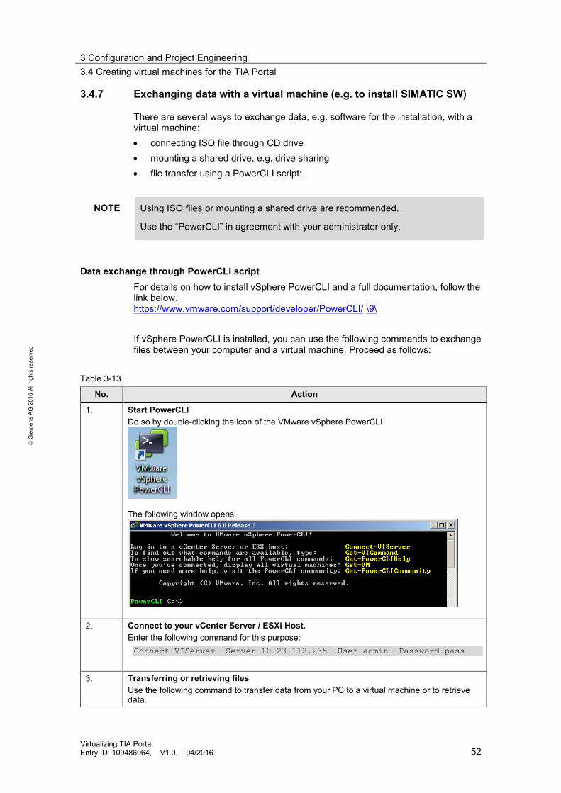
3.4.7 Exchanging data with a virtual machine (e.g. to install SIMATIC SW)
There are several ways to exchange data, e.g. software for the installation, with a virtual machine: • connecting ISO file through CD drive • mounting a shared drive, e.g. drive sharing • file transfer using a PowerCLI script:
NOTE Using ISO files or mounting a shared drive are recommended.
Use the “PowerCLI” in agreement with your administrator only.
Data exchange through PowerCLI script For details on how to install vSphere PowerCLI and a full documentation, follow the link below. https://www.vmware.com/support/developer/PowerCLI/ \9\ If vSphere PowerCLI is installed, you can use the following commands to exchange files between your computer and a virtual machine. Proceed as follows:
Table 3-13
No. Action
1. Start PowerCLI Do so by double-clicking the icon of the VMware vSphere PowerCLI
The following window opens.
2. Connect to your vCenter Server / ESXi Host. Enter the following command for this purpose: Connect-VIServer -Server 10.23.112.235 -User admin -Password pass
3. Transferring or retrieving files
Use the following command to transfer data from your PC to a virtual machine or to retrieve data.

3 Configuration and Project Engineering 3.4 Creating virtual machines for the TIA Portal
Virtualizing TIA Portal Entry ID: 109486064, V1.0, 04/2016 53
S
iem
ens
AG 2
016
All r
ight
s re
serv
ed
No. Action • Transferring data from your PC to the virtual machine: "GuestToLocal". • Retrieving data from the virtual machine to your PC: "LocalToGuest". Copy-VMGuestFile -Source c:\text.txt -Destination c:\temp\ - VM NAME_OF_YOUR_VM -LocalToGuest -HostUser USER_NAME_OF_THE_ESXI_HOST -HostPassword PASWWORD_OF_THE_ESXI_HOST -GuestUser WINDOWSUSER-GuestPassword PASSWORD_FOR_WINDOWSUSER
This instruction copies the file text.txt from your computer's C partition to a virtual machine named NAME_OF_YOUR_VM to the path c:\temp.
4. End transfer Use the following command to end the transfer and release the resources again. Disconnect-VIServer 10.23.112.235
3.4.8 Time synchronization
Synchronizing the virtual machines The host (ESXi) must use the same time source as the operating systems within the virtual machines. Before time synchronization mechanisms take effect in the virtual machine, the host's time is used when starting the virtual machine. If the two times differ, undesired behavior can occur as a result. Use one of the two methods of time synchronization in the virtual machine: • VMware Tools or
• another time synchronization method, e.g. WinCC mechanisms
For more information, see the Online Support, Entry ID: "86535497". https://support.industry.siemens.com/cs/ww/en/view/86535497).
NOTICE The two methods used to synchronize the virtual machine time (e.g. NTP) and VMware Tools (time synchronization with the host) must not be used at the same time.

3 Configuration and Project Engineering 3.4 Creating virtual machines for the TIA Portal
Virtualizing TIA Portal Entry ID: 109486064, V1.0, 04/2016 54
S
iem
ens
AG 2
016
All r
ight
s re
serv
ed
Synchronization of the hosts The ESXi hosts need a time source. Set this source accordingly using the vSphere Client. Figure 3-20 NTP Server Configuration in the vSphere Client
Figure 3-21 NTP server configuration in the vSphere Web Client
3.4.9 Installing SIMATIC software
If the virtual machine contains the installation sources, you can install the SIMATIC SW as usual. For more information, refer to the system manuals. • STEP 7 Professional V13 SP1
https://support.industry.siemens.com/cs/de/en/view/109011420 \11\ • WinCC Professional V13 SP1
https://support.industry.siemens.com/cs/ww/en/view/109096785 \12\

4 Further Notes, Tips and Tricks 4.1 General recommendations
Virtualizing TIA Portal Entry ID: 109486064, V1.0, 04/2016 55
S
iem
ens
AG 2
016
All r
ight
s re
serv
ed
4 Further Notes, Tips and Tricks 4.1 General recommendations
Snapshots Do not use snapshots during productive operation. This can negatively affect the virtual machine's general performance capability. For more information, follow this link: https://www.vmware.com/pdf/vcops-vapp-585-deploy-guide.pdf (p. 15) \6\ Search KB entry 1025279 "Snapshots are not backups" for "Best practices for virtual machine snapshots in the VMware environment". https://kb.vmware.com/selfservice/microsites/microsite.do \5\
vMotion or vMotion Storage Do not use vMotion or vMotion Storage for virtual machines in which SIMATIC software is active.
VMware Tools Install the latest version of the VMware Tools.
Hard drives Thick Provision Eager Zeroed format Create the hard drives in the format "Thick Provision Eager Zeroed". It will provide the best performance properties. For more information, follow this link: https://www.vmware.com/pdf/vcops-vapp-585-deploy-guide.pdf (p. 15) \6\ Distributing multiple hard drives of a virtual machine Distribute the hard drives evenly across the virtual SCSI adapters. For more information, see the book "Virtualizing Microsoft Business Critical Applications on VMware vSphere" (p. 90). \7\ I/O intensive applications Use the paravirtual storage adapter (PVSCSI) for I/O intensive applications. It reduces the CPU load and is capable of improving especially the system's overall performance. Also observe the information provided by the following links. For more information, follow this link: https://www.vmware.com/pdf/Perf_Best_Practices_vSphere5.5.pdf (p. 50) \8\ or in the KB article 1010398. Look for "Configuring disks to use VMware Paravirtual SCSI adapters". https://kb.vmware.com/selfservice/microsites/microsite.do \7\

4 Further Notes, Tips and Tricks 4.2 Important security settings
Virtualizing TIA Portal Entry ID: 109486064, V1.0, 04/2016 56
S
iem
ens
AG 2
016
All r
ight
s re
serv
ed
Unnecessary hardware in virtual machines Remove all unnecessary hardware from the configuration. Each unnecessary element can negatively affect the performance capability of your virtual machine. For more information, follow this link: https://www.vmware.com/pdf/Perf_Best_Practices_vSphere5.5.pdf (p. 19) \8\ This includes: • floppy disk • CD ROM • HD audio •
4.2 Important security settings
Based on the "Hardening Guide", make the following settings to assure that the SIMATIC products run smoothly. The guide gives a detailed description of additional measures. For more information, follow this link: https://www.vmware.com/security/hardening-guides \13\
Disabling automatic updating of VMware Tools An automatic upgrade of the VMware Tools can cause the host operating system to be restarted automatically. During reboot a WinCC Server is not accessible or WinCC Client is not operable. Disable automatic installation:
Use PowerCli as described in section 3.4.7 Exchanging data with a virtual machine. 1. Connect to your vCenter Server / ESXi Host. 2. Connect-VIServer -Server 10.23.112.235 -User admin -Password pass 3. Enter the following command: 4. VM.disable-VMtools-autoinstall= True (Get-VM| New-AdvancedSetting -Name
"isolation.tools.autoInstall.disable" -value $true) 5. Log off: 6. Disconnect-VIServer 10.23.112.235 7. For other ways to make this change, see the VMware Hardening Guide.
Time synchronization through NTP Synchronize your ESXi host with a time source. Use the same time source as for time synchronization of your operating systems within the VMs. For more details, see chapter 3.4.8.

4 Further Notes, Tips and Tricks 4.3 Compilation times
Virtualizing TIA Portal Entry ID: 109486064, V1.0, 04/2016 57
S
iem
ens
AG 2
016
All r
ight
s re
serv
ed
Applying patches for ESXi Always keep the patches of your ESXi hosts up to date. You can do so using the Update Manager for example.
NOTICE Reboot of host required and with that rebooting virtual machines is required.
For successful installation of patches a reboot is required mostly. With that virtual machines have to reboot too.
WinCC Servers are not accessible or WinCC Clients are not operable during this.
For more information, follow this link: https://www.vmware.com/support/policies/security_response \14\
4.3 Compilation times
The compilation times of the engineering station strongly depend on the CPU in use. For this project, two vCPUs were assigned to the engineering station, measuring the times for compiling on different hosts and different data stores. Table 4-1 shows these values. Table 4-1 Compilation times
No. Store system Host name
Time in minutes and seconds for 4 compilations and their average
1. DotHill (Raid 5) 61 47:40 - 41:26 - 41:42 - 40:00 ∅ 42:52 2. Dot Hill Fast (Raid 10) 61 37:43 - 40:51 - 39:58 - 45:27 ∅ 41:00 3. IBM Datastore (Raid 5) 61 38:59 - 40:04 - 40:42 - 40:47 ∅ 40:08 4. DotHill (Raid 5) 51 20:20 - 20:33 - 19:47 - 20:21 ∅ 20:15 5. Dot Hill Fast (Raid 10) 51 8:01 PM - 8:11 PM - 7:44 PM - 7:32 PM
∅ 7:52 PM 6. IBM Datastore (Raid 5) 51 8:50 PM - 8:01 PM - 8:38 PM - 8:48 PM
∅ 8:34 PM 7. DotHill – CPU reserv. 51 7:15 PM - 7:17 PM - 7:08 PM - 7:06 PM
∅ 7:11 PM
The table below gives an overview of the CPU types used. Table 4-2 Hosts and performance features
Host name
Processor type CPU cores RAM
51 Intel Xeon E5-2680 v3 @ 2.5GHz 24 CPUs 262039.60 MB 61 Intel Xeon E7540 @ 2.0GHz 24 CPUs 393087.10 MB
The measured values show a clear dependence between the compilation time and the CPU used. The data store plays a minor role in this context. Given the shared use of CPU, RAM and data store, the values may vary as a function of the host's overall utilization and the Hypervisor's scheduling behavior.

4 Further Notes, Tips and Tricks 4.4 Troubleshooting and performance
Virtualizing TIA Portal Entry ID: 109486064, V1.0, 04/2016 58
S
iem
ens
AG 2
016
All r
ight
s re
serv
ed
Reserving the CPU for the engineering station slightly reduces the time. This is shown in line 7 of the Table 4-1. 4800 MHz were reserved exclusively for this virtual machine. However, the full extend is only used during compilation. For the remaining time, it is not used.
Note Reserving resources can boost the virtual machine's performance. But the reserved resources are then no longer available to other virtual machines and hence limit the number of possible virtual machines on this host. Avoid reservations.
4.4 Troubleshooting and performance VMware provides various means to diagnose performance bottlenecks. Below, we will briefly describe use of the vSphere Client and of the "esxtop" tool. For more information, see the manual "vSphere Monitoring and Performance". https://www.vmware.com/support/pubs/ \4\
4.4.1 Performance monitoring with vSphere Client or Web Client
The performance of each virtual machine can be monitored. Click the "Performance" tab for this purpose. It shows various views in tables or charts, giving a quick overview of the current and past situation of your virtual machine. The diagnosis should always be made at the Hypervisor level and not in the virtual machine. The overview includes: • CPU • RAM • datastore
vSphere Client Figure 4-1 vSphere Client performance monitoring
vSphere Web Client In the Web Client this view is accessible at "Monitor" and "Performance".

4 Further Notes, Tips and Tricks 4.4 Troubleshooting and performance
Virtualizing TIA Portal Entry ID: 109486064, V1.0, 04/2016 59
S
iem
ens
AG 2
016
All r
ight
s re
serv
ed
Figure 4-2 vSphere Web Client performance monitoring
4.4.2 ESXTOP
The tool esxtop / resxtop provides detailed insight. To use esxtop, perform the following steps:
Table 4-3
No. Action
1. Activate SSH Activate SSH on the host. You need to do this for each host where SSH is needed. Adjust the firewall rules accordingly. In the vSphere Client: • Select the "Configuration" tab. • Select the "Security Profile" in the "Software" section. • Select the properties under "Services" and • activate SSH.

4 Further Notes, Tips and Tricks 4.4 Troubleshooting and performance
Virtualizing TIA Portal Entry ID: 109486064, V1.0, 04/2016 60
S
iem
ens
AG 2
016
All r
ight
s re
serv
ed
No. Action
In the vSphere Web Client • Expand the "System" section. • Select "Security Profile". • Then select "Edit Security Profile" and • activate SSH.

4 Further Notes, Tips and Tricks 4.4 Troubleshooting and performance
Virtualizing TIA Portal Entry ID: 109486064, V1.0, 04/2016 61
S
iem
ens
AG 2
016
All r
ight
s re
serv
ed
No. Action
2. Session login • Log in to the console, e.g. using putty.
• Enter the address of your ESXi host.
3. esxtop Enter the login data and start esxtop.
4. The following overview opens (example).

4 Further Notes, Tips and Tricks 4.4 Troubleshooting and performance
Virtualizing TIA Portal Entry ID: 109486064, V1.0, 04/2016 62
S
iem
ens
AG 2
016
All r
ight
s re
serv
ed
4.4.3 Examples
Below we will present some typical scenarios that impair the virtual machine's performance and its proper behavior. The diagnosis is demonstrated using esxtop and the two client variants.
CPU If CPU utilization is permanently at 100% or near 100%, check the configuration of your virtual machine. The following illustration shows the curve of an engineering station. The two highlighted areas are two compilation processes of the TIA Portal. High utilization is normal during these phases. Subsequently, the curve drops visibly.
Figure 4-3 CPU usage during compilation
Example of a CPU diagnosis: Enter the following commands in esxtop:
8. c for cpu 9. V to display VMs 10. e and the GID of the virtual machine to display the individual vCPUs
The relevant columns are %RDY, %CSTP and %MLMTD. %RDY shows the time in percent a virtual machine must wait for an allocation. The engineering station is depicted with one line per allocated CPU core in the illustration. Values of more than 10% in the %RDY column indicate too many vCPUs of the virtual machine, or in this case, a set limit of the CPU resource. This is visible in the %MLMTD column.

4 Further Notes, Tips and Tricks 4.4 Troubleshooting and performance
Virtualizing TIA Portal Entry ID: 109486064, V1.0, 04/2016 63
S
iem
ens
AG 2
016
All r
ight
s re
serv
ed
Figure 4-4 esxtop CPU limit
Another example shows how the engineering station is influenced by a virtual machine on the same host. 16 vCPUs on a host with just 12 physical cores per CPU were allocated to this second virtual machine. This also impairs the engineering station's performance as is indicated by the elevated value in the %RDY column. 7.61 in the example.
Figure 4-5 esxtop CPU impact
RAM Allocate RAM appropriately. Excessive RAM per virtual machine will equally result in unnecessary administration overhead. Make sure not to overcommit RAM especially when it comes to virtual machines for SIMATIC software. Use of the Balloon driver and swapping processes are among the first signs of trouble with RAM allocation. Make sure that: • Balloon is at 0 KB and • no swapping is taking place Figure 4-6 shows the normal behavior. If Balloon or swapping increase, this indicates problems in the form of insufficient RAM.

4 Further Notes, Tips and Tricks 4.4 Troubleshooting and performance
Virtualizing TIA Portal Entry ID: 109486064, V1.0, 04/2016 64
S
iem
ens
AG 2
016
All r
ight
s re
serv
ed
Figure 4-6 RAM profile – Balloon consumes 0 KB
Hard drives Increased latency times of the hard drives impair the performance of the operating systems within the virtual machines and hence the running applications. If the applications respond poorly, check the latency times of the hard drives using vSphere Client or esxtop. The following illustrations show extremely high latency times, both on average and maximum. In this case, the store system cannot satisfy the requests of the virtual machine, making the virtual machines nearly impossible to operate.
Figure 4-7 Latency times in the vSphere Client
Figure 4-8 Latency times in the vSphere Web Client

4 Further Notes, Tips and Tricks 4.4 Troubleshooting and performance
Virtualizing TIA Portal Entry ID: 109486064, V1.0, 04/2016 65
S
iem
ens
AG 2
016
All r
ight
s re
serv
ed
Figure 4-9 Latency times with esxtop
The following latencies were measured over a period of 14 days for the virtualized TIA project.
Figure 4-10 Latency times of the engineering station
Figure 4-11 Latencies of Client1
Figure 4-12 Latencies of WinCC Server
Network A source of error may also be located in the network. If packets are discarded within the virtual network, this can be determined using network diagnostic tools. The following figure shows the discarded receive packets after blocking of a port group.
Figure 4-13 Discarded packets in the vSphere Client

4 Further Notes, Tips and Tricks 4.4 Troubleshooting and performance
Virtualizing TIA Portal Entry ID: 109486064, V1.0, 04/2016 66
S
iem
ens
AG 2
016
All r
ight
s re
serv
ed
Figure 4-14 Discarded packets in the vSphere Web Client
In esxtop the discarded packets are shown as percentages. In this example, only the port group of the terminal bus network is affected. Enter the following commands in esxtop:
11. n for network 12. f to add columns 13. Make sure that DRPTX/s and DRPRX/s are selected.
Figure 4-15 Discarded packets esxtop

5 Related Literature
Virtualizing TIA Portal Entry ID: 109486064, V1.0, 04/2016 67
S
iem
ens
AG 2
016
All r
ight
s re
serv
ed
5 Related Literature Table 5-1
Topic
\1\ Siemens Industry Online Support https://support.industry.siemens.com
\2\ This entry https://support.industry.siemens.com/cs/ww/en/view/109486064
\3\ HCL – Hardware Compatibility List https://www.vmware.com/resources/compatibility/search.php
\4\ VMware Documentation https://www.vmware.com/support/pubs/
\5\ VMware Knowledge Base https://kb.vmware.com/selfservice/microsites/microsite.do
\6\ vApp Deployment and Configuration Guide https://www.vmware.com/pdf/vcops-vapp-585-deploy-guide.pdf
\7\ Virtualizing Microsoft Business Critical Applications on VMware vSphere - Matt Liebowitz, Alexander Fontana- 2013 – ISBN 0321912039
\8\ Performance Best Practices for VMware vSphere® 5.5 https://www.vmware.com/pdf/Perf_Best_Practices_vSphere5.5.pdf
\9\ Documentation PowerCLI https://www.vmware.com/support/developer/PowerCLI/
\10\ Time synchronization - Time synchronization in the automation environment https://support.industry.siemens.com/cs/tr/tr/view/86535497/en
\11\ "STEP 7 Professional V13 SP1" Manual https://support.industry.siemens.com/cs/tr/en/view/109011420
\12\ WinCC Professional V13 SP1 https://support.industry.siemens.com/cs/tr/en/view/109096785
\13\ Hardening Guide https://www.vmware.com/security/hardening-guides
\14\ Security Response Policy https://www.vmware.com/support/policies/security_response

6 List of Abbreviations
Virtualizing TIA Portal Entry ID: 109486064, V1.0, 04/2016 68
S
iem
ens
AG 2
016
All r
ight
s re
serv
ed
6 List of Abbreviations E E/A Eingabe/Ausgabe ES Engineering Station ESXi Hypervisor zur Virtualisierung F FC Fibre Channel FT Fault Tolerance H HBA Host Bus Adapter HCL Hardware Compatibility List I IOPs Input/Output Operations Per Second iSCSI internet Small Computer System Interface N NFS Network File System NIC Network Interface Card NTP Network Time Protocol P P2V Physical to Virtual R RAID Redundant Array of Independent Disks S SAN Storage Area Network, Speichernetzwerk SAS Serial Attached SCSI SCSI Small Computer System Interface SID Security Identifier SSH Secure Shell V V2V Virtual to Virtual VM virtuelle Maschine vmdk Virtual Machine Disk, Dateityp/-endung VMXNET virtual network adapter vSS vSphere Standard Switch
7 History Table 7-1
Version Date Modifications
V1.0 03/2016 First version