Embed Size (px)
Citation preview
Chapter ➃ Application Design 1 5
C H A P T E R ➃
Application DesignChapter Objectives
The information in this chapter will enable you to the following:
❏ Recognize and understand important considerations that must be addressedbefore you implement your application
❏ Understand the capabilities of the system❏ Customize the system to meet your requirements
The X language command examples in this chapter are tailored to single-axis operation. To use these examples for multi-axis simulation, change theaxis-specific prefix for each command (1, 2, or 3). If an axis is not specified,the OEMØ23-AT defaults to axis #1.
Application ConsiderationsSuccessful application of a rotary indexer system requires carefulconsideration of the following important factors:
❏ Mechanical resonance❏ Ringing or overshoot❏ Move times (calculated vs. actual)❏ Positional accuracy and repeatability
Mechanical ResonanceResonance, a characteristic of all stepper motors, can cause the motor to stallat low speeds. Resonance occurs at speeds that approach the naturalfrequency of the motor's rotor and the first and second harmonics of thosespeeds. It causes the motor to vibrate at these speeds. The speed at whichfundamental resonance occurs is typically between 0.3 and 0.8 revs per secondand is highest for small motors and lowest for large motors.
Most full-step motor controllers jump the motor to a set minimum startingspeed to avoid this resonance region. This causes poor performance belowone rev per second. In nearly all cases, using a microstepping drive with theOEMØ23-AT will overcome these problems.
☞ Helpful HintViscous dampermanufacturer:Ferrofluidics Corp.40 Simon StreetNashua, NH 03061(603) 883-9800
Motors that will not accelerate past one rev per second may be stalling due toresonance. The resonance point may be lowered to some extent by addinginertia to the motor shaft. This may be accomplished by putting a drillchuck on the back shaft. This technique is applicable only to double-shaftmotors with the shaft extending from both ends of the motor. In extremecases, you may also need a viscous damper to balance the load. Changing thevelocity (V command) and acceleration (A command) may resolve aresonance problem.
1 6 OEMØ23-AT Indexer User Guide
Ringing or OvershootThe motor's springiness, along with its mass, form an underdampedresonant system that rings in response to acceleration transients (such as atthe end of a move). Ringing at the end of a move prolongs settling time.Overshoot occurs when the motor rotates beyond the actual final position.The actual settling time of a system depends on the motor's stiffness, themass of the load, and any frictional forces that may be present. By adding alittle friction, you can decrease the motor's settling time.
Move Times: Calculated vs. ActualYou can calculate the time required to complete a move by using theacceleration, velocity, and distance values that you define with the A, V, andD software commands respectively. However, you should not assume thatthe values that you use will constitute the actual move time. After you issuethe Go (G) command, the OEMØ23-AT may take up to 50 ms to calculate themove before the motor starts moving. You should also expect some time toelapse for the motor and the load to settle.
Positional Accuracy vs. RepeatabilityIn positioning systems, some applications require high absolute accuracy.Others require repeatability. You should clearly define and distinguishthese two concepts when you address the issue of system performance.
If the positioning system is taken to a fixed place and the coordinates of thatpoint are recorded, the only concern is how well the system repeats when youcommand it to go back to the same point. For many systems, what is meantby accuracy is really repeatability. Repeatability measures how accuratelyyou can repeat moves to the same position.
Accuracy, on the other hand, is the error in finding a random position. Forexample, suppose the job is to measure the size of an object. The size of theobject is determined by moving the positioning system to a point on theobject and using the move distance required to get there as the measurementvalue. In this situation, basic system accuracy is important. The systemaccuracy must be better than the tolerance on the measurement that isdesired.
For more information on accuracy and repeatability, consult the technicaldata section of the Compumotor Programmable Motion Control Catalog.
Open LoopAccuracy
Open-loop absolute accuracy of a step motor is typically less than aprecision-grade system, but is better than most tangential drive systems.When you close the loop with an incremental encoder, the accuracy of thesesystems is equivalent to the encoder's accuracy.
The worst-case accuracy of the system is the sum of the following errors.Accuracy = A + B.
A Uni-directional Repeatability: The error measured by repeated moves tothe same point from different distances in the same direction.
B Hysteresis: The backlash of the motor and mechanical linkage when itchanges direction due to magnetic and mechanical friction.
Chapter ➃ Application Design 1 7
Using Terminal Emulation ModeCompumotor recommends that you become familiar with the OEMØ23-AT'sX language commands in Terminal Emulation Mode before you create yourcustom programs in another language. Terminal Emulation mode is a user-friendly menu-driven program that allows you to use X Language commandsdirectly. After you are familiar with the X language, you can develop customprogram routines (pre-tested in Terminal Emulation mode).
☞ Helpful HintSteps to enter TerminalEmulation mode
➀ Type OEM23TRM at the OEMØ23-AT prompt.➁ Enter device address 768.
Positioning ModesYou can use one of three positioning modes to run the motor with X languagecommands—normal (preset), alternating, and continuous.
Normal (Preset) ModeYou can select preset moves by putting the OEMØ23-AT into normal modeusing the Mode Normal (MN) command. Preset moves allow you to position themotor in relation to the motor's previous stopped position (incrementalmoves) or in relation to a defined zero reference position (absolute moves).You can select incremental moves by using the Mode Position Incremental(MPI or FSAØ) command. You can select absolute moves using the ModePosition Absolute (MPA or FSA1) command.
Incremental ModeMoves
When using the Incremental mode (MPI or FSAØ), a preset move moves theshaft of the motor the specified distance from its starting position. Forexample, to move the motor shaft 1.5 revolutions, specify a preset move with adistance of +37,500 steps (1.5 revs @ 25,000 steps/rev). Every time the indexerexecutes this move, the motor moves 1.5 revs from its resting position. Youcan specify the direction of the move with the optional sign (D+375ØØ or D-375ØØ), or define it separately with the Set Direction (H) command (H+ or H-)after the D command. If you do not specify the direction (e.g., D25ØØØ), theunit defaults to the positive (CW) direction.
SampleIncrementalMode Moves
The moves below are incremental moves. The distance specified is relativeto the motor’s current position. This is the default (power-up) positioningmode.
☞ Helpful HintThe motor moves one CWrevolution and stops. It thenmoves one more CWrevolution in the samedirection and stops. Themotor changes direction andmoves one CCW revolution.
Command DescriptionMPI Sets unit to Incremental Position modeA2 Sets acceleration to 2 rps2
V5 Sets velocity to 5 rpsD25ØØØ Sets distance to 25,000 stepsG Executes the move (Go)G Repeats the move (Go)H Reverses direction of next moveG Executes the move (Go)
☞ Helpful HintThe motor returns to itsoriginal starting position.
Command DescriptionD-25ØØØ Sets the distance to 25,000 steps in the negative (CCW) directionG Executes the move (Go)
☞ Helpful HintThe motor moves 25,000steps in the positive (CW)direction.
Command DescriptionH Toggles the motor direction of the next move, but maintains existing acceleration,
velocity, and distance parameters.G Executes the same move profile as the previous move, but in opposite direction (Go)
To load all the commands before executing them, use the Pause (PS) andContinue (C) commands.
Command DescriptionPS Pauses execution until the indexer receives a Continue (C) commandG Executes a 25,000-step move (Go)T3 Waits 3 seconds after the moveG Executes another 25,000-step move (Go)C Cancels pause and executes the G T3 G commands
1 8 OEMØ23-AT Indexer User Guide
Absolute PresetMode Moves
A preset move in the Absolute mode moves the motor the distance that youspecify (in motor steps) from the absolute zero position. You can set theabsolute position to zero with the Position Zero (PZ) command, issuing theGo Home (GH) command, or by cycling the power to the indexer.
The direction of an absolute preset move depends upon the motor position atthe beginning of the move and the position you command it to move to. Forexample, if the motor is at absolute position +12,500, and you instruct themotor to move to position +5,000, the motor will move in the negativedirection a distance of 7,500 steps to reach the absolute position of +5,000.
When you issue the Mode Position Absolute (MPA or FSA1) command, it setsthe mode to absolute. When you issue the Mode Position incremental (MPI orFSAØ) command the unit switches to Incremental mode. The OEMØ23-ATretains the absolute position, even while the unit is in the incrementalmode. You can use the Position Report (PR) command to read the absoluteposition.
SampleAbsoluteMoves
The moves shown below are absolute mode moves. The distance specified isrelative to the OEMØ23-AT's absolute zero position.
Command DescriptionMN Sets the OEMØ23-AT to Normal modeMPA Sets the OEMØ23-AT to the Absolute Positioning modePZ Sets the current absolute position to zeroA5 Sets acceleration to 5 rps2
V3 Sets velocity to 3 rpsD5ØØØ Sets move to absolute position 5,000G Executes move (motor moves to absolute position 5,000)
Command DescriptionD1ØØØØ Sets the motor to absolute position 10,000. (Since the motor was already at
position 5,000, it will move 5,000 additional steps in the CW direction.)G Executes the move (Go)DØ Sets the motor to absolute position 0. (Since the motor is at absolute position
10,000, the motor will move 10,000 steps in the CCW direction.)G Executes the move (Go)
Alternating Mode☞ Helpful HintThis indexing mode is notfunctional when the absolutepositioning mode is selected(MPA or FSA1).
You can select the Alternating mode with the MA command. Set-up forAlternating mode is identical to that for Normal mode (MN). The difference isthat when you issue the Go (G) command, the motor shaft rotates to thecommanded position that corresponds to the value set by the D command,and then retraces its path back to the start position. The shaft continues tomove between the start position and the command position. Normally, themotor stops immediately when you issue an S command. However, if youissue the SSD1 command before the G command, then when you issue the Scommand, the motor completes the cycle and stops at the start position.Another Go (G) command will repeat the same motion pattern.
Continuous ModeThe Continuous mode (MC) is useful for applications that require constantmovement of the load, when the motor must stop after a period of time haselapsed (rather than after a fixed distance), or when the motor must besynchronized to external events such as trigger input signals. You canmanipulate the motor movement with either buffered or immediatecommands. After you issue the G command, buffered commands areexecuted in the order in which they were programmed. While the motor is incontinuous motion, you can change the velocity and acceleration by issuinga new V and A command followed by a G command.
Chapter ➃ Application Design 1 9
SampleContinuousMode Move
The following example demonstrates a continuous mode sequence.
Command DescriptionMC Sets to Continuous modeA1Ø Sets acceleration to 10 rps2
V1 Sets velocity to 1 rpsG Executes the move (Go)
Motor accelerates to 1 rps and continues at that same rate until you issue theS command, or until the load triggers an end-of-travel limit switch.
The following example demonstrates how to change the acceleration andvelocity while the motor is moving (on-the-fly) in Continuous mode.
Command DescriptionMC Sets all moves to the Continuous modeA1 Sets acceleration to 1 rps2
V.5 Sets final velocity to 0.5 rpsG Executes move (motor travels at 1 rps)A10 Sets acceleration to 10 rps2
V.4 Sets velocity to 0.4 rpsG Changes velocity to 0.4 rps at 10 rps2
V.1 Sets velocity to 0.1 rpsG Changes velocity to 0.1 rps
Move ParametersFor rotary motors, velocity and acceleration parameters are expressed inunits of motor revolutions. For accurate speed control, each axis needs toknow its motor's resolution. Use the MR command to change motorresolution from the default (25,000 steps/rev) as required. This parameteralso controls step pulse width and velocity range. Refer to the description ofthe MR command in OEMØ23-AT Software Reference Guide.
It is desirable in many applications for the distance parameter to bespecified in units other than motor steps, such as hundredths of a degree orthousandths of an inch. If the desired units correspond to an integer numberof motor steps, the indexer's position multiplier (US command) capabilitycan used to scale the D command position parameter to those units for anyaxis.
Example A 25,000-step/rev motor drives a 5-turn/inch lead screw. The systemresolution is 125,000 steps per inch. To express the distance parameter inthousandths of an inch, the operator uses the US125 command to set adistance multiplier of 125. If he then gives a distance command D1ØØØ, themotor will move 1,000 units of 125 steps each (one inch) on the next go (G)command. For more information, refer to the US command description inOEMØ23-AT Software Reference Guide.
When scale factors greater than 1 are used, and an indexed move isinterrupted by a Stop (S) command or by activation of a limit switch, thefinal position may not be a multiple of the scale factor. Consequently, therepeatability of that move is lost.
2 0 OEMØ23-AT Indexer User Guide
Program ControlThis section discusses the X language program control features of theOEMØ23-AT.
LoopsYou may use the Loop (L) command to repeat certain sequences. You can nestloop commands up to 8 levels deep.
Command DescriptionPS Pauses command execution until the indexer receives a Continue (C) commandMPI Sets mode to incrementalA5 Sets acceleration to 5 rps2
V5 Sets velocity to 5 rpsL5 Loops 5 timesD2ØØØ Sets distance to 2,000 stepsG Executes the move (Go)T2 Delays 2 seconds after the moveN Ends Loop structureC Initiates command execution to resume
The example below shows how you can nest a small loop inside a major loop.In this example, the motor makes 2 moves and returns a carriage return.The unit repeats these procedures and will continue to repeat until youinstruct the unit to stop immediately with an S (Stop) or K (Kill) command. Ifyou issue a Y (Stop Loop) command, the OEMØ23-AT finishes the currentloop of commands and then stops the motor.
Command DescriptionPS Pauses command execution until the indexer receives a Continue (C) command
Loops indefinitelySends a carriage returnLoops twiceExecutes 2,000-step moveWaits 0.5 secondsEnds loopEnds loop
LoopLoop
L1CRL2GT.5NNC Cancels pause and Initiates command execution
POBs (Programmable Output Bits)You can turn the programmable outputs on and off using the Output(O)command. Zero (Ø) turns off a given output and one (1) turns the outputon. The outputs conduct when they are on and do not conduct when they areoff (see the O command description in the OEMØ23-AT SoftwareReference Guide).
Command DescriptionMN Set move to Mode NormalPS Pauses execution until indexer receives a Continue (C) commandA1Ø Sets acceleration to 10 rps2
V5 Sets velocity to 5 rpsD25ØØØ Sets move distance to 25,000 stepsO1ØXXX Sets POB 1 on and POB 2 off and leaves the rest unchangedG Executes the move (Go)C Cancels the Pause and executes the move
Move Completion SignalsWhen you complete a move, you may use the OEMØ23-AT's programmingcapability to signal the end of the current move. In a preset move, you mayuse one of the following commands:
❏ Carriage return (CR)❏ Output command (O)❏ Status request command (PR reports motor's absolute position)
Chapter ➃ Application Design 2 1
You may also use the moving/stopped bits of the status byte (SB) register todetermine if an axis has completed its move.
☞ Helpful HintThe motor moves 12,500steps. When the move iscomplete, the OEMØ23-ATissues a carriage return,turns on POB #3, reports themotor's absolute position,and reports the encoder'sabsolute position.
Command DescriptionPS Pauses command execution until the indexer receives a Continue (C) commandA2 Sets acceleration to 2 rps2
V.1 Sets velocity to 0.1 rpsD125ØØ Sets distance to 12,500 stepsG Executes the move (Go)1CR Sends a carriage return over the interfaceOXX1XXX Turns on Output #3 (ignores the other POBs)1PR Report absolute positionC Cancels the Pause and executes the move
Custom ProfilesYou can define a custom non-linear motion profile with the OEMØ23-AT'sVelocity Streaming modes. The three Velocity Streaming modes that theOEMØ23-AT offers are listed below.
❏ Immediate Velocity (Q1 command)❏ Time-Distance (Q2 command)❏ Time-Velocity (Q3 command)
When you select Velocity Streaming mode (Q1), the OEMØ23-AT makesimmediate velocity changes based on parameters you set with Set ImmediateVelocity (RM) commands. The timing between issuing each RM commanddetermines the exact move profile (refer to the Immediate VelocityStreaming section latter in this chapter).
The Time-Distance (Q2) mode allows you to specify an update period atwhich the OEMØ23-AT travels the next distance that you specify.
The Time-Velocity (Q3) mode is very similar to the Time-Distance (Q2) mode,except that the variable parameter is the velocity.
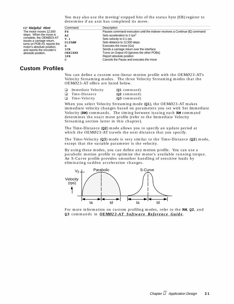
By using these modes, you can define any motion profile. You can use aparabolic motion profile to optimize the motor's available running torque.An S-Curve profile provides smoother handling of sensitive loads byeliminating sudden acceleration changes.
V f
Velocity(rps)
ta td ta td
Parabolic S-Curve
For more information on custom profiling modes, refer to the RM, Q2, andQ3 commands in OEMØ23-AT Software Reference Guide.
2 2 OEMØ23-AT Indexer User Guide
Immediate Velocity Streaming ModeIn this mode, the host computer software supplies a stream of velocity data(X language RM commands) for real-time control of motor speed. TheOEMØ23-AT has no control of acceleration. The operator controls allvelocity changes. If the motor changes too abruptly for the motor to follow,the motor will stall or fault.
Once this operating mode is entered with the Q1 command, the OEMØ23-ATclears out any buffered commands waiting for execution and waits for RateMultiplier in Velocity Streaming mode (RM) commands. With thesecommands, the OEMØ23-AT makes instantaneous changes to the specifiedvelocity. The timing between issuing each RM command determines theexact move profile. Sending RM commands to the OEMØ23-AT in rapidsuccession provides smoother motion by virtue of an S-curve acceleration.Testing and modification may be required to establish the correct sequenceof RM commands.
CAUTIONDo not make the velocity changes too abrupt. Abrupt velocity changes may stall the motor.
In the default high velocity range, with the default motor resolution (25,000steps/rev) and a 25,000-step motor, a data increment of 1 produces a velocityincrement of about 15.259 steps per second.
RM commands are executed immediately. Consequently, it is not possible todownload a list of RM values to the OEMØ23-AT, and execute it afterward.
To exit Velocity Profiling mode, you must use the QØ command. When a Q1 orQØ command is received, it is performed before any buffered commands.
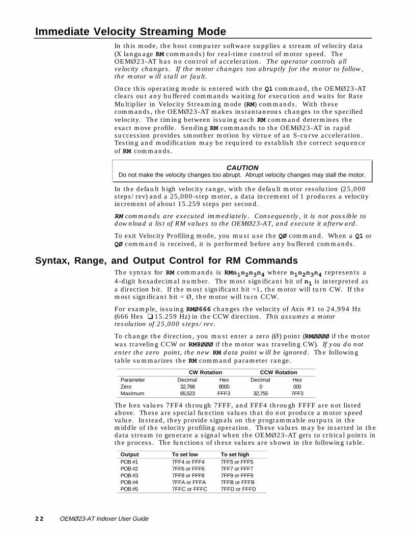
Syntax, Range, and Output Control for RM CommandsThe syntax for RM commands is RMn1n2n3n4 where n1n2n3n4 represents a4-digit hexadecimal number. The most significant bit of n1 is interpreted asa direction bit. If the most significant bit =1, the motor will turn CW. If themost significant bit = Ø, the motor will turn CCW.
For example, issuing RMØ666 changes the velocity of Axis #1 to 24,994 Hz(666 Hex ❏ 15.259 Hz) in the CCW direction. This assumes a motorresolution of 25,000 steps/rev.
To change the direction, you must enter a zero (Ø) point (RMØØØØ if the motorwas traveling CCW or RM8ØØØ if the motor was traveling CW). If you do notenter the zero point, the new RM data point will be ignored. The followingtable summarizes the RM command parameter range.
CW Rotation CCW RotationParameter Decimal Hex Decimal HexZero 32,768 8000 0 000Maximum 65,523 FFF3 32,755 7FF3
The hex values 7FF4 through 7FFF, and FFF4 through FFFF are not listedabove. These are special function values that do not produce a motor speedvalue. Instead, they provide signals on the programmable outputs in themiddle of the velocity profiling operation. These values may be inserted in thedata stream to generate a signal when the OEMØ23-AT gets to critical points inthe process. The functions of these values are shown in the following table.
Output To set low To set highPOB #1 7FF4 or FFF4 7FF5 or FFF5POB #2 7FF6 or FFF6 7FF7 or FFF7POB #3 7FF8 or FFF8 7FF9 or FFF9POB #4 7FFA or FFFA 7FFB or FFFBPOB #5 7FFC or FFFC 7FFD or FFFD
Chapter ➃ Application Design 2 3
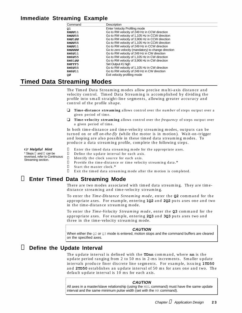
Immediate Streaming ExampleCommand DescriptionQ1 Enter Velocity Profiling modeRMØØ11 Go to RM velocity of 249 Hz in CCW directionRMØØ55 Go to RM velocity of 1,105 Hz in CCW directionRMØ1ØØ Go to RM velocity of 3,906 Hz in CCW directionRMØØ55 Go to RM velocity of 1,105 Hz in CCW directionRMØØ11 Go to RM velocity of 249 Hz in CCW directionRMØØØØ Go to zero velocity (mandatory) to change directionRM8Ø11 Go to RM velocity of 249 Hz in CW directionRM8Ø55 Go to RM velocity of 1,105 Hz in CW directionRM81ØØ Go to RM velocity of 3,906 Hz in CW directionRMFFF5 Set Output #1 highRM8Ø55 Go to RM velocity of 1,105 Hz in CW directionRM8Ø11 Go to RM velocity of 249 Hz in CW directionQØ Exit velocity profiling mode
Timed Data Streaming ModesThe Timed Data Streaming modes allow precise multi-axis distance andvelocity control. Timed Data Streaming is accomplished by dividing theprofile into small straight-line segments, allowing greater accuracy andcontrol of the profile shape.
❏ Time-distance streaming allows control over the number of steps output over agiven period of time.
❏ Time-velocity streaming allows control over the frequency of steps output overa given period of time.
In both time-distance and time-velocity streaming modes, outputs can beturned on or off on-the-fly (while the motor is in motion). Wait-on-triggerand looping are also possible in these timed data streaming modes. Toproduce a data streaming profile, complete the following steps.
☞ Helpful Hint* Steps ➃ and ➄ can bereversed, refer to ContinuousStreaming section.
➀ Enter the timed data streaming mode for the appropriate axes.➁ Define the update interval for each axis.➂ Identify the clock source for each axis.➃ Provide the time-distance or time velocity streaming data.*➄ Start the master clock.*➅ Exit the timed data streaming mode after the motion is completed.
➀ Enter Timed Data Streaming ModeThere are two modes associated with timed data streaming. They are time-distance streaming and time-velocity streaming.
To enter the Time-Distance Streaming mode, enter the Q2 command for theappropriate axes. For example, entering 1Q2 and 2Q2 puts axes one and twoin the time-distance streaming mode.
To enter the Time-Velocity Streaming mode, enter the Q3 command for theappropriate axes. For example, entering 2Q3 and 3Q3 puts axes two andthree in the time-velocity streaming mode.
CAUTIONWhen either the Q2 or Q3 mode is entered, motion stops and the command buffers are clearedon the specified axes.
➁ Define the Update IntervalThe update interval is defined with the TDnn command, where nn is theupdate period ranging from 2 to 50 ms in 2-ms increments. Smaller updateintervals produce finer discrete line segments. For example, issuing 1TD50and 2TD50 establishes an update interval of 50 ms for axes one and two. Thedefault update interval is 10 ms for each axis.
CAUTIONAll axes in a master/slave relationship (using the MSL command) must have the same updateinterval and the same minimum pulse width (set with the MR command).
2 4 OEMØ23-AT Indexer User Guide
➂ Identify Clock SourceUsing the MSL command, you must specify the clock source for each axis. Indoing this, you determine the master/slave relationship of the axes to oneanother or to other boards. The MSL command must be specified in the formMSLn1n2n3, where each nn value represents the clock source for axes ➀through ➂.
Axis #1 For Axis #1, the possible values for n1 are as follows:
1 If axis #1 uses its own internal clock (master)2 If axis #1 uses axis #2's internal clock (slave to axis #2)3 If axis #1 uses axis #3's internal clock (slave to axis #3)X If axis #1 is not in Data Streaming modeØ If axis #1 uses an external clock connected to pins 1 and 2 on the RMCLK slave-to-
external connector (refer to Chapter ➄ Hardware Reference for connections)
Axis #2 For Axis #2, the possible values for n2 are as follows:
1 If axis #2 uses axis #1's internal clock (slave to axis #1)2 If axis #2 uses its own internal clock (master)3 If axis #2 uses axis #3's internal clock (slave to axis #3)X If axis #2 is not in Data Streaming modeØ If axis #1 and #2 uses an external clock (via the RMCLK connector)
Axis #3 For Axis #3, the possible values for n3 are as follows:
1 If axis #3 uses axis #1's internal clock (slave to axis #1)2 If axis #3 uses axis #2's internal clock (slave to axis #2)3 If axis #3 uses its own internal clock (master)X If axis #3 is not in Data Streaming modeØ If axis #1, #2, and #3 uses an external clock (via the RMCLK connector)
CAUTIONNever overlap clock sources. For instance, do not issue MSL21X, where axis #2 would useaxis #1's clock source and axis #1 would use axis #2's clock.
When using the external clock, axis #1 must always use the external clockand be set to a data streaming mode (1Q2 or 1Q3). If the command string1Q2 2Q2 3Q2 MSLXØØ was issued, the MSLXØØ command would be invalidbecause axis 1 is not using an external clock.
The most common use of the MSL command is to specify one axis as the masterwhile other axes follow the master. For example, if you use the MSL111command, axis #1 is the master and axes #2 and #3 follow axis #1.
➃ Establish Timed Data Streaming Format and DataThe Streaming Data (SD) command specifies either the distance to travel (inthe Q2 mode) or the velocity output (in Q3 mode) in one update period.Special data points implement certain functions such as loops, setting thePOBs, and waiting for a specific trigger input pattern. Data-intensivestreaming on one axis is likely to reduce command throughput on the otheraxes that are not in streaming mode.
The format for the SD command is SDnnnn(nnnn[nnnn]), where nnnn is a2, 4, or 6 byte HEX code. If one axis is in Streaming mode, the format isSDnnnn. If two axes are in Streaming mode, the format is SDnnnnnnnn. Ifall three axes are in Streaming mode, the format is SDnnnnnnnnnnnn.
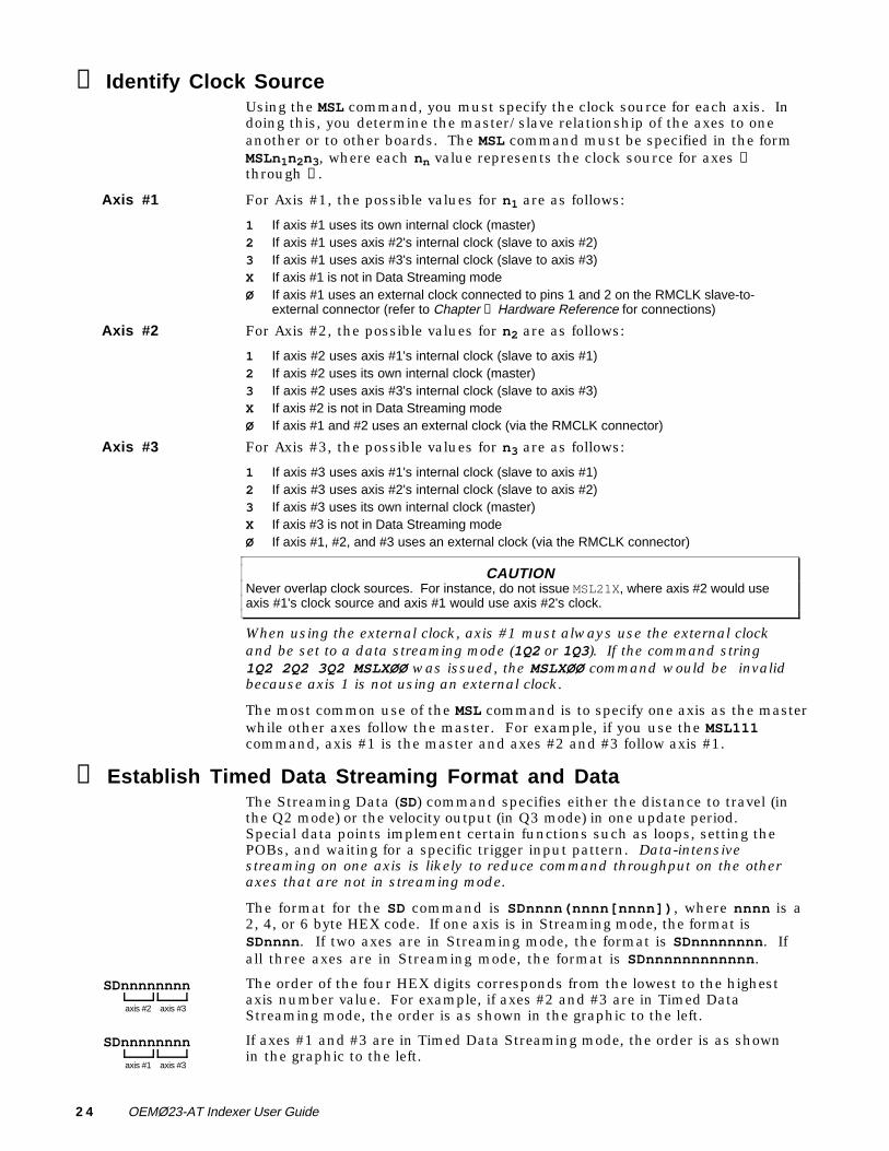
SDnnnnnnnn
axis #2 axis #3
The order of the four HEX digits corresponds from the lowest to the highestaxis number value. For example, if axes #2 and #3 are in Timed DataStreaming mode, the order is as shown in the graphic to the left.
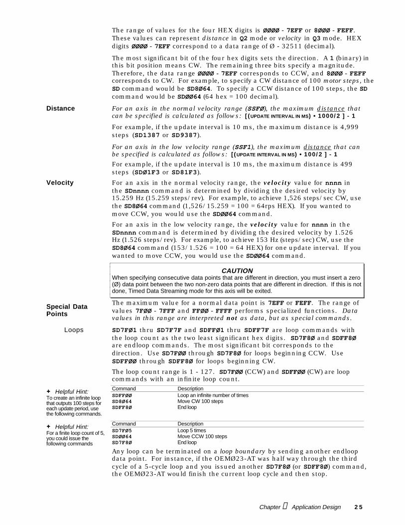
SDnnnnnnnn
axis #1 axis #3
If axes #1 and #3 are in Timed Data Streaming mode, the order is as shownin the graphic to the left.
Chapter ➃ Application Design 2 5
The range of values for the four HEX digits is ØØØØ - 7EFF or 8ØØØ - FEFF.These values can represent distance in Q2 mode or velocity in Q3 mode. HEXdigits ØØØØ - 7EFF correspond to a data range of Ø - 32511 (decimal).
The most significant bit of the four hex digits sets the direction. A 1 (binary) inthis bit position means CW. The remaining three bits specify a magnitude.Therefore, the data range ØØØØ - 7EFF corresponds to CCW, and 8ØØØ - FEFFcorresponds to CW. For example, to specify a CW distance of 100 motor steps, theSD command would be SD8Ø64. To specify a CCW distance of 100 steps, the SDcommand would be SDØØ64 (64 hex = 100 decimal).
Distance For an axis in the normal velocity range (SSFØ), the maximum distance thatcan be specified is calculated as follows: [ (UPDATE INTERVAL IN MS) • 1000/ 2 ] - 1
For example, if the update interval is 10 ms, the maximum distance is 4,999steps (SD1387 or SD9387).
For an axis in the low velocity range (SSF1), the maximum distance that canbe specified is calculated as follows: [ (UPDATE INTERVAL IN MS) • 100/ 2 ] - 1
For example, if the update interval is 10 ms, the maximum distance is 499steps (SDØ1F3 or SD81F3).
Velocity For an axis in the normal velocity range, the velocity value for nnnn inthe SDnnnn command is determined by dividing the desired velocity by15.259 Hz (15.259 steps/rev). For example, to achieve 1,526 steps/sec CW, usethe SD8Ø64 command (1,526/15.259 = 100 = 64rps HEX). If you wanted tomove CCW, you would use the SDØØ64 command.
For an axis in the low velocity range, the velocity value for nnnn in theSDnnnn command is determined by dividing the desired velocity by 1.526Hz (1.526 steps/rev). For example, to achieve 153 Hz (steps/sec) CW, use theSD8Ø64 command (153/1.526 = 100 = 64 HEX) for one update interval. If youwanted to move CCW, you would use the SDØØ64 command.
CAUTIONWhen specifying consecutive data points that are different in direction, you must insert a zero(Ø) data point between the two non-zero data points that are different in direction. If this is notdone, Timed Data Streaming mode for this axis will be exited.
Special DataPoints
The maximum value for a normal data point is 7EFF or FEFF. The range ofvalues 7FØØ - 7FFF and FFØØ - FFFF performs specialized functions. Datavalues in this range are interpreted not as data, but as special commands.
Loops SD7FØ1 thru SD7F7F and SDFFØ1 thru SDFF7F are loop commands withthe loop count as the two least significant hex digits. SD7F8Ø and SDFF8Øare endloop commands. The most significant bit corresponds to thedirection. Use SD7FØØ through SD7F8Ø for loops beginning CCW. UseSDFFØØ through SDFF8Ø for loops beginning CW.
The loop count range is 1 - 127. SD7FØØ (CCW) and SDFFØØ (CW) are loopcommands with an infinite loop count.
+ Helpful Hint:To create an infinite loopthat outputs 100 steps foreach update period, usethe following commands.
Command DescriptionSDFFØØ Loop an infinite number of timesSD8Ø64 Move CW 100 stepsSDFF8Ø End loop
+ Helpful Hint:For a finite loop count of 5,you could issue thefollowing commands
Command DescriptionSD7FØ5 Loop 5 timesSDØØ64 Move CCW 100 stepsSD7F8Ø End loop
Any loop can be terminated on a loop boundary by sending another endloopdata point. For instance, if the OEMØ23-AT was half way through the thirdcycle of a 5-cycle loop and you issued another SD7F8Ø (or SDFF8Ø) command,the OEMØ23-AT would finish the current loop cycle and then stop.
2 6 OEMØ23-AT Indexer User Guide
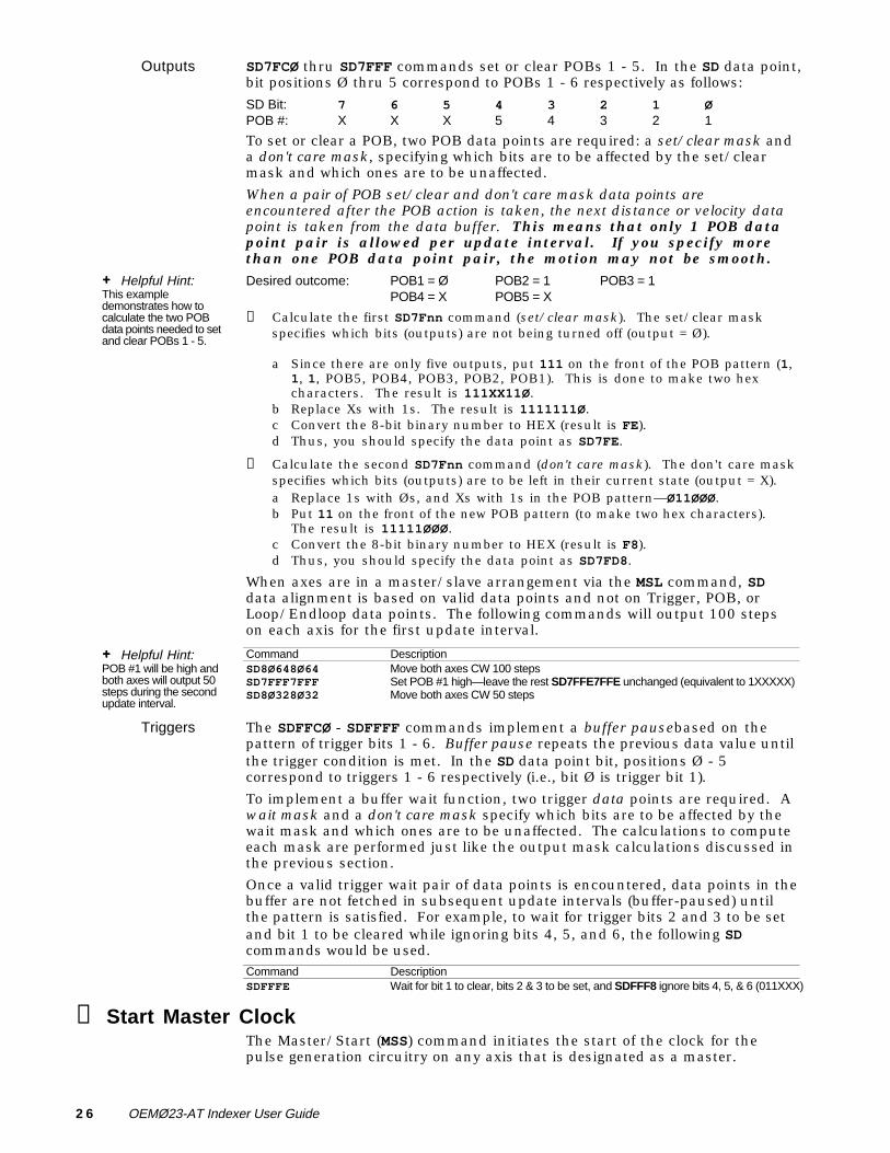
Outputs SD7FCØ thru SD7FFF commands set or clear POBs 1 - 5. In the SD data point,bit positions Ø thru 5 correspond to POBs 1 - 6 respectively as follows:
SD Bit: 7 6 5 4 3 2 1 ØPOB #: X X X 5 4 3 2 1
To set or clear a POB, two POB data points are required: a set/clear mask anda don't care mask, specifying which bits are to be affected by the set/clearmask and which ones are to be unaffected.
When a pair of POB set/clear and don't care mask data points areencountered after the POB action is taken, the next distance or velocity datapoint is taken from the data buffer. This means that only 1 POB datapoint pair is allowed per update interval. If you specify morethan one POB data point pair, the motion may not be smooth.
+ Helpful Hint:This exampledemonstrates how tocalculate the two POBdata points needed to setand clear POBs 1 - 5.
Desired outcome: POB1 = Ø POB2 = 1 POB3 = 1POB4 = X POB5 = X
➀ Calculate the first SD7Fnn command (set/clear mask). The set/clear maskspecifies which bits (outputs) are not being turned off (output = Ø).
a Since there are only five outputs, put 111 on the front of the POB pattern (1,1, 1, POB5, POB4, POB3, POB2, POB1). This is done to make two hexcharacters. The result is 111XX11Ø.
b Replace Xs with 1s. The result is 1111111Ø.c Convert the 8-bit binary number to HEX (result is FE).d Thus, you should specify the data point as SD7FE.
➁ Calculate the second SD7Fnn command (don't care mask). The don't care maskspecifies which bits (outputs) are to be left in their current state (output = X).a Replace 1s with Øs, and Xs with 1s in the POB pattern—Ø11ØØØ.b Put 11 on the front of the new POB pattern (to make two hex characters).
The result is 11111ØØØ.c Convert the 8-bit binary number to HEX (result is F8).d Thus, you should specify the data point as SD7FD8.
When axes are in a master/slave arrangement via the MSL command, SDdata alignment is based on valid data points and not on Trigger, POB, orLoop/Endloop data points. The following commands will output 100 stepson each axis for the first update interval.
+ Helpful Hint:POB #1 will be high andboth axes will output 50steps during the secondupdate interval.
Command DescriptionSD8Ø648Ø64 Move both axes CW 100 stepsSD7FFF7FFF Set POB #1 high—leave the rest SD7FFE7FFE unchanged (equivalent to 1XXXXX)SD8Ø328Ø32 Move both axes CW 50 steps
Triggers The SDFFCØ - SDFFFF commands implement a buffer pausebased on thepattern of trigger bits 1 - 6. Buffer pause repeats the previous data value untilthe trigger condition is met. In the SD data point bit, positions Ø - 5correspond to triggers 1 - 6 respectively (i.e., bit Ø is trigger bit 1).
To implement a buffer wait function, two trigger data points are required. Await mask and a don't care mask specify which bits are to be affected by thewait mask and which ones are to be unaffected. The calculations to computeeach mask are performed just like the output mask calculations discussed inthe previous section.
Once a valid trigger wait pair of data points is encountered, data points in thebuffer are not fetched in subsequent update intervals (buffer-paused) untilthe pattern is satisfied. For example, to wait for trigger bits 2 and 3 to be setand bit 1 to be cleared while ignoring bits 4, 5, and 6, the following SDcommands would be used.Command DescriptionSDFFFE Wait for bit 1 to clear, bits 2 & 3 to be set, and SDFFF8 ignore bits 4, 5, & 6 (011XXX)
➄ Start Master ClockThe Master/Start (MSS) command initiates the start of the clock for thepulse generation circuitry on any axis that is designated as a master.
Chapter ➃ Application Design 2 7
Data Streaming RestrictionsThe following are restrictions to be considered when using the Timed DataStreaming mode:
❏ If the master/slave relationship with another board is desired, then axis #1must be included as a streaming axis, and must use the external clock.
❏ The minimum motor resolution required is 5,000 steps/rev.❏ All master/slave axes must have the same velocity range (SSF command).❏ If a limit is hit while in Timed Data Streaming mode (Q2 or Q3), Timed Data
Streaming mode is exited for that axis only (equivalent to a QØ command).❏ For update periods of 6 ms or less, binary input mode is recommended (see
below).❏ While streaming in a master/slave relationship, all slave axes should be exited
first, before the master axis. For example, when operating axis 1 through 3under the command MSL111, you should exit as follows: 3QØ ... 2QØ ... 1QØ.
❏ Discrete data streaming is limited by the OEMØ23-AT buffer size (seeContinuous Streaming discussed later in this chapter).
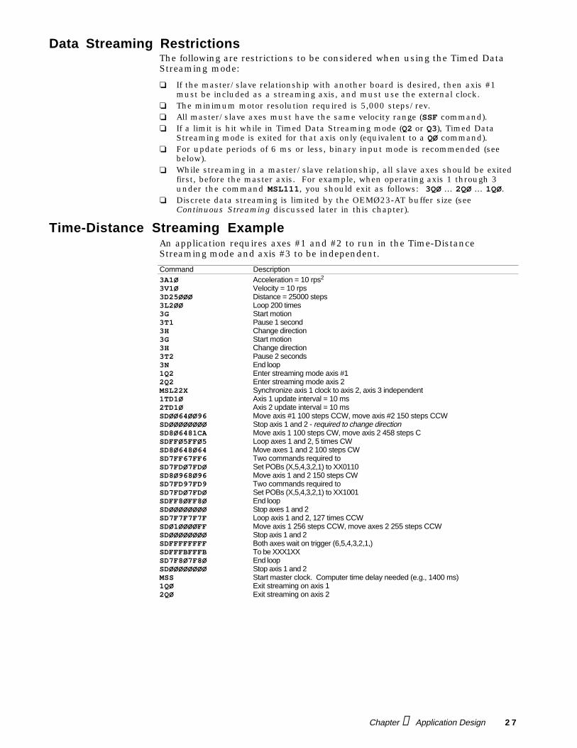
Time-Distance Streaming ExampleAn application requires axes #1 and #2 to run in the Time-DistanceStreaming mode and axis #3 to be independent.
Command Description3A1Ø Acceleration = 10 rps2
3V1Ø Velocity = 10 rps3D25ØØØ Distance = 25000 steps3L2ØØ Loop 200 times3G Start motion3T1 Pause 1 second3H Change direction3G Start motion3H Change direction3T2 Pause 2 seconds3N End loop1Q2 Enter streaming mode axis #12Q2 Enter streaming mode axis 2MSL22X Synchronize axis 1 clock to axis 2, axis 3 independent1TD1Ø Axis 1 update interval = 10 ms2TD1Ø Axis 2 update interval = 10 msSDØØ64ØØ96 Move axis #1 100 steps CCW, move axis #2 150 steps CCWSDØØØØØØØØ Stop axis 1 and 2 - required to change directionSD8Ø6481CA Move axis 1 100 steps CW, move axis 2 458 steps CSDFFØ5FFØ5 Loop axes 1 and 2, 5 times CWSD8Ø648Ø64 Move axes 1 and 2 100 steps CWSD7FF67FF6 Two commands required toSD7FDØ7FDØ Set POBs (X,5,4,3,2,1) to XX0110SD8Ø968Ø96 Move axis 1 and 2 150 steps CWSD7FD97FD9 Two commands required toSD7FDØ7FDØ Set POBs (X,5,4,3,2,1) to XX1001SDFF8ØFF8Ø End loopSDØØØØØØØØ Stop axes 1 and 2SD7F7F7F7F Loop axis 1 and 2, 127 times CCWSDØ1ØØØØFF Move axis 1 256 steps CCW, move axes 2 255 steps CCWSDØØØØØØØØ Stop axis 1 and 2SDFFFFFFFF Both axes wait on trigger (6,5,4,3,2,1,)SDFFFBFFFB To be XXX1XXSD7F8Ø7F8Ø End loopSDØØØØØØØØ Stop axis 1 and 2MSS Start master clock. Computer time delay needed (e.g., 1400 ms)1QØ Exit streaming on axis 12QØ Exit streaming on axis 2
2 8 OEMØ23-AT Indexer User Guide
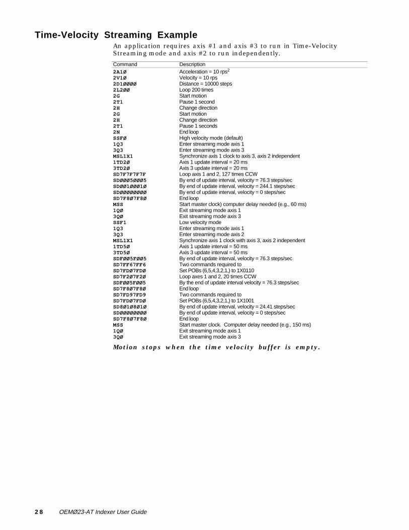
Time-Velocity Streaming ExampleAn application requires axis #1 and axis #3 to run in Time-VelocityStreaming mode and axis #2 to run independently.
Command Description2A1Ø Acceleration = 10 rps2
2V1Ø Velocity = 10 rps2D1ØØØØ Distance = 10000 steps2L2ØØ Loop 200 times2G Start motion2T1 Pause 1 second2H Change direction2G Start motion2H Change direction2T1 Pause 1 seconds2N End loopSSFØ High velocity mode (default)1Q3 Enter streaming mode axis 13Q3 Enter streaming mode axis 3MSL1X1 Synchronize axis 1 clock to axis 3, axis 2 independent1TD2Ø Axis 1 update interval = 20 ms3TD2Ø Axis 3 update interval = 20 msSD7F7F7F7F Loop axis 1 and 2, 127 times CCWSDØØØ5ØØØ5 By end of update interval, velocity = 76.3 steps/secSDØØ1ØØØ1Ø By end of update interval, velocity = 244.1 steps/secSDØØØØØØØØ By end of update interval, velocity = 0 steps/secSD7F8Ø7F8Ø End loopMSS Start master clock) computer delay needed (e.g., 60 ms)1QØ Exit streaming mode axis 13QØ Exit streaming mode axis 3SSF1 Low velocity mode1Q3 Enter streaming mode axis 13Q3 Enter streaming mode axis 2MSL1X1 Synchronize axis 1 clock with axis 3, axis 2 independent1TD5Ø Axis 1 update interval = 50 ms3TD5Ø Axis 3 update interval = 50 msSDFØØ5FØØ5 By end of update interval, velocity = 76.3 steps/secSD7FF67FF6 Two commands required toSD7FDØ7FDØ Set POBs (6,5,4,3,2,1,) to 1X0110SD7F2Ø7F2Ø Loop axes 1 and 2, 20 times CCWSDFØØ5FØØ5 By the end of update interval velocity = 76.3 steps/secSD7F8Ø7F8Ø End loopSD7FD97FD9 Two commands required toSD7FDØ7FDØ Set POBs (6,5,4,3,2,1,) to 1X1001SD8Ø1Ø8Ø1Ø By end of update interval, velocity = 24.41 steps/secSDØØØØØØØØ By end of update interval, velocity = 0 steps/secSD7F8Ø7F8Ø End loopMSS Start master clock. Computer delay needed (e.g., 150 ms)1QØ Exit streaming mode axis 13QØ Exit streaming mode axis 3
Motion stops when the time velocity buffer is empty.
Chapter ➃ Application Design 2 9
Discrete Data StreamingThe previous time-distance and velocity-distance examples use what isreferred to as discrete data streaming, which follows this pattern.
➀ Q2 or Q3 Enter time-distance or velocity-distance mode➁ TD Provide time-distance update rate or period➂ MSL Specify master/slave clock source➃ SD Specify stream data or send distance➄ MSS Master/slave start (start movement)➅ QØ Exit time-distance mode
This form of streaming is useful when the number of SD data points does notexceed the OEMØ23-AT's buffer capacity. Since each axis buffer can hold1,000 characters, this corresponds to about 200 SD data points per axis(1,000 bytes @ 5 bytes per SD data point).
By using discrete streaming, the standard communication handshaking canbe used (refer to TERMINAL.BAS, OEM23P.PAS, or OEM23C.C on thesupport disks). Discrete streaming also allows update intervals of 2 ms to beused without using the binary input mode or assembly language drivers.
Continuous Data StreamingContinuous data streaming differs from discrete data streaming in that theSD data points are sent to the OEMØ23-AT after starting the master clock,instead of before starting the master clock. By choosing continuousstreaming over discrete streaming, you are not limited by the OEMØ23-ATbuffer. Therefore, you can send an infinite number of SD data points to theOEMØ23-AT.
CAUTIONYou must check bit 7 of the status byte to ensure that the OEMØ23-AT data buffer is able tohandle the data. The buffer cannot accept new data until bit 7 changes from Ø to 1. You cansend up to 200 data points (2 bytes per point) at one time and wait for bit 7 to change from Ø to1 to send 200 more.
The command sequence required to conduct a continuous streamingoperation for each axis is as follows:
➀ Q2 or Q3 Enter time-distance or velocity-distance mode➁ MSL Specify master/slave clock source➂ TD Provide time-distance update rate or period➃ MSS Master/slave start (start movement)➄ SD Specify velocity or # of steps to output➅ QØ Exit time-distance mode
Step ➄ can be accomplished in two different ways. One way is by repeatedlyusing the standard OEMØ23-AT write drivers (refer to the TERMINAL.BAS,OEM23P.PAS, or OEM23C.C programs on the support disk). The otherapproach is to use the OEMØ23-AT's binary input capability (describedbelow)—files OEM23TDP.PAS and OEM23TDC.C.
3 0 OEMØ23-AT Indexer User Guide
Binary Input ModeBy using the binary input mode, you can use a much faster update rate.Having a shorter update interval allows more precise control of the motionsegments. Within the binary input mode, the data points are entered asbinary words. Therefore, when you enter data this way, only two, four, or sixbytes (for one, two, or three axes) per input session are allowed. During eachinput session, one SD data point (for 1, 2, or 3 axes) is transferred to theOEMØ23-AT.
+ Helpful Hint:The following steps arerequired to support abinary data input modesession.
➀ Read the status byte (base address + 1) until bit 4 is set (OEMØ23-AT ready toreceive a byte).
➁ Send one byte of the 2, 4, or 6-byte data packet to the OEMØ23-AT dataregister (base address).
➂ Send HEX 71 to the control byte (base address +1). This puts the OEMØ23-ATin binary input mode and informs the OEMØ23-AT that a data byte has beentransferred to it.
➃ Read the status byte until bit 4 is cleared (data byte accepted by OEMØ23-AT)➄ If the data byte that you sent in step 2 is the last byte of the 2, 4, or 6-byte
packet, send HEX 6Ø to the control byte (exit binary input mode). If the databyte sent in step 2 is not the last byte, send HEX 61 (remain in binary inputmode) to the control byte and repeat steps 1 through 5.
Binary Input mode will work only in Continuous Streamingmode.
Example Axes #1 and #2 are in the time-distance mode (Q2) with axis #1 as the masterand axis #2 as the slave, using the step pulse clock from axis #1 (i.e.,MSL11X). The update rate is 2 ms (TD2).
To input a data point so that axis #1 outputs 100 steps CW for one updateperiod and axis #2 outputs 200 CW steps for the same period, two binarywords (4 bytes) are sent in one binary input mode session as follows (thesequential order is from top to bottom).
Command DescriptionMSB1 HEX 80 (binary, not ASCII)LSB1 HEX 64MSB2 HEX 80LSB2 HEX C8
On software support disk #2, binary input mode examples are written in twodifferent program languages: PASCAL and C.
Language ConsiderationsWhen creating a program in the timed data streaming mode, you mustconsider the programming language you are using. Certain languages, suchas C, run considerably faster than BASIC. PASCAL also runs faster thanBASIC, even a compiled BASIC, such as Microsoft™ QuickBASIC.
On tests performed with an IBM compatible (80286 microprocessor), BorlandTURBO C 2.0 was able to run a continuous timed data streaming programwith an update interval of 6 ms (TD6). This program used the binary inputmode to communicate SD data points to the OEMØ23-AT. Using BorlandTURBO PASCAL 5.0, a similar program ran at 12 ms update intervals(TD12). Using Microsoft Quick BASIC 4.5, a comparable program ran at 30ms update intervals (TD3Ø).
If you require update intervals of 2 ms, you must use assembly languagebinary input mode drivers. By linking these assembly language routinesinto your BASIC, C, or PASCAL program, you will be able to obtain 2 msupdate intervals, even on a standard PC with an 8088 microprocessor.
Examples of how to link the assembly language binary input mode driversare provided on the support disk. For BASIC, reference the \BAS_ASMsubdirectory. For C, reference the \C_ASM subdirectory. For PASCAL,reference the \PAS_ASM subdirectory.
Chapter ➃ Application Design 3 1
Communicating with the OEMØ23-ATThis section describes how the computer communicates with the OEMØ23-AT.
Read and Write RegistersTo operate the OEMØ23-AT with X language commands and sequences, you mustbe able to communicate with it via the computer's I/O bus. OEMØ23-ATcommunication involves two pairs of registers. A register is a temporarystorage area for holding one character (or one eight-bit byte). Data transfer toand from the register occurs one character at a time.
+ Helpful Hint:Sample read and writeroutines that access thecomputer's I/O bus are ondemonstration diskettes thataccompany the OEMØ23-AT(routines written in BASIC,C, and PASCAL.)
Register pair #1 resides at the OEMØ23-AT's bases address set with the 8-position DIP switch and consists of the input data buffer (IDB) and the outputdata buffer (ODB). Register pair #2 resides at one address location abovethe OEMØ23-AT's bases address and consists of the control byte (CB) and thestatus byte (SB). The ODB and the SB are read-only registers. The IDB andthe CB are write-only registers.
Control Byte and Status ByteX language commands are strings of ASCII characters. Sending a commandto the OEMØ23-AT requires transferring each character in the string one at atime. Each character transfer requires the sender to notify the receiver thata character is ready and the receiver to notify the sender that the characterhas been received. This notification process involves setting or clearingcontrol bits (flags) in the 8- bit SB and CB registers.
❏ Set = high = binary value of 1❏ Clear = low = binary value of Ø
Control Byte flags allow the host program to signal the OEMØ23-AT withmessages such as "A1Ø V1Ø D25ØØØ G". Status Byte flags allow the hostprogram to check the OEMØ23-AT’s operating conditions (e.g., motor C oraxis #2 is moving).
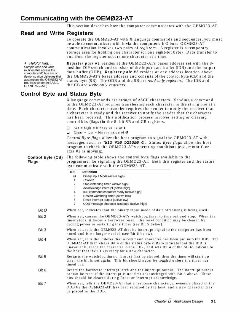
Control Byte (CB)Flags
The following table shows the control byte flags available to theprogrammer for signaling the OEMØ23-AT. Both this register and the statusbyte communicate with the OEMØ23-AT.
Bit DefinitionØ Binary Input Mode (active high)1 Unused2 Stop watchdog timer (active high)3 Acknowledge interrupt (active high)4 IDB command character ready (active high)5 Restart watchdog timer (active low)6 Reset interrupt output (active low)7 ODB message character accepted (active high)
Bit Ø When set, indicates that the binary input mode of data streaming is being used.
Bit 2 When set, causes the OEMØ23-AT's watchdog timer to time out and stop. When thetimer stops, it forces a hardware reset. The reset condition may be cleared bycycling power or restarting the timer (see Bit 5 below).
Bit 3 When set, tells the OEMØ23-AT that its interrupt signal to the computer has beennoted and is no longer needed (see Bit 6 below).
Bit 4 When set, tells the indexer that a command character has been put into the IDB. TheOEMØ23-AT then clears Bit 4 of the status byte (SB) to indicate that the IDB isunavailable, reads the character in the IDB , and sets Bit 4 of the SB to indicate tothe host that the IDB is ready for a new character.
Bit 5 Restarts the watchdog timer. It must first be cleared, then the timer will start upwhen the bit is set again. This bit should never be toggled unless the timer hastimed out.
Bit 6 Resets the hardware interrupt latch and the interrupt output. The interrupt outputcannot be reset if the interrupt is not first acknowledged with Bit 3 above. Thesebits should be cleared during Reset or Interrupt acknowledge.
Bit 7 When set, tells the OEMØ23-AT that a response character, previously placed in theODB by the OEMØ23-AT, has been received by the host, and a new character maybe placed in the ODB.
3 2 OEMØ23-AT Indexer User Guide
Status Byte (SB)Flags
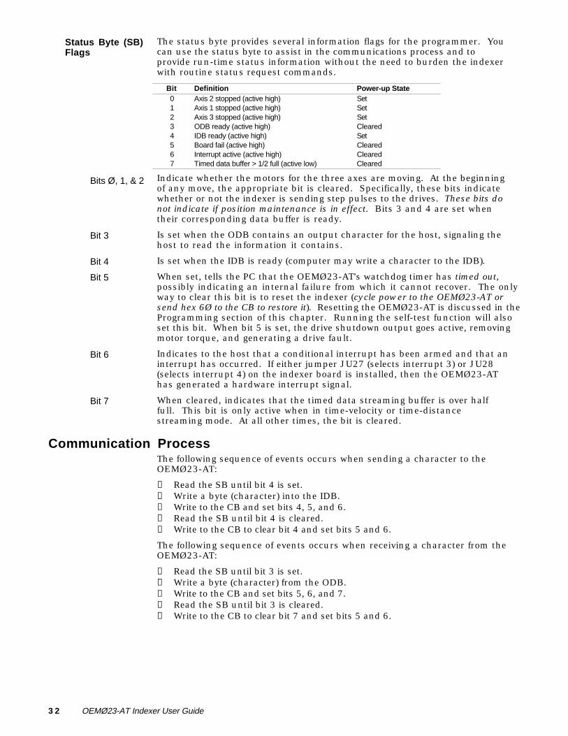
The status byte provides several information flags for the programmer. Youcan use the status byte to assist in the communications process and toprovide run-time status information without the need to burden the indexerwith routine status request commands.
Bit Definition Power-up State0 Axis 2 stopped (active high) Set1 Axis 1 stopped (active high) Set2 Axis 3 stopped (active high) Set3 ODB ready (active high) Cleared4 IDB ready (active high) Set5 Board fail (active high) Cleared6 Interrupt active (active high) Cleared7 Timed data buffer > 1/2 full (active low) Cleared
Bits Ø, 1, & 2 Indicate whether the motors for the three axes are moving. At the beginningof any move, the appropriate bit is cleared. Specifically, these bits indicatewhether or not the indexer is sending step pulses to the drives. These bits donot indicate if position maintenance is in effect. Bits 3 and 4 are set whentheir corresponding data buffer is ready.
Bit 3 Is set when the ODB contains an output character for the host, signaling thehost to read the information it contains.
Bit 4 Is set when the IDB is ready (computer may write a character to the IDB).
Bit 5 When set, tells the PC that the OEMØ23-AT's watchdog timer has timed out,possibly indicating an internal failure from which it cannot recover. The onlyway to clear this bit is to reset the indexer (cycle power to the OEMØ23-AT orsend hex 6Ø to the CB to restore it). Resetting the OEMØ23-AT is discussed in theProgramming section of this chapter. Running the self-test function will alsoset this bit. When bit 5 is set, the drive shutdown output goes active, removingmotor torque, and generating a drive fault.
Bit 6 Indicates to the host that a conditional interrupt has been armed and that aninterrupt has occurred. If either jumper JU27 (selects interrupt 3) or JU28(selects interrupt 4) on the indexer board is installed, then the OEMØ23-AThas generated a hardware interrupt signal.
Bit 7 When cleared, indicates that the timed data streaming buffer is over halffull. This bit is only active when in time-velocity or time-distancestreaming mode. At all other times, the bit is cleared.
Communication ProcessThe following sequence of events occurs when sending a character to theOEMØ23-AT:
➀ Read the SB until bit 4 is set.➁ Write a byte (character) into the IDB.➂ Write to the CB and set bits 4, 5, and 6.➃ Read the SB until bit 4 is cleared.➄ Write to the CB to clear bit 4 and set bits 5 and 6.
The following sequence of events occurs when receiving a character from theOEMØ23-AT:
➀ Read the SB until bit 3 is set.➁ Write a byte (character) from the ODB.➂ Write to the CB and set bits 5, 6, and 7.➃ Read the SB until bit 3 is cleared.➄ Write to the CB to clear bit 7 and set bits 5 and 6.
Chapter ➃ Application Design 3 3
ProgrammingThe OEMØ23-AT includes a support disk containing support routineswritten in Quick BASIC, C, and PASCAL. ASSEMBLY routines to reset, read,and write to the OEMØ23-AT are also included.
The support disk are divided logically into subdirectories. To go betweenthese subdirectories type: cd(subdirectory name). To back up onesubdirectory type: cd..
☞ Helpful Hint:A terminal emulator programis also included with thesupport code. This program(OEM23TRM.EXE) talks tothe OEMØ23-AT directly. Itis a good program to practicemaking motion with theOEMØ23-AT.
❏ The Quick BASIC support routine is contained in the QBASIC subdirectory.❏ The C support routine is contained in the C subdirectory.❏ The PASCAL support routine is contained in the PASCAL subdirectory.
The ASSEMBLY routines are in the QBAS_ASM, C_ASM, and PAS_ASMsubdirectories. Each of these subdirectories show how to link ASSEMBLY codeto the appropriate programming language (Quick BASIC, C, or PASCAL).
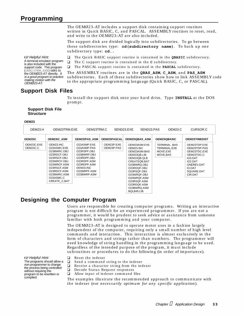
Support Disk FilesTo install the support disk onto your hard drive. Type INSTALL at the DOSprompt.
Support Disk FileStructure
OEM23
OEM23.H OEM23TRM.C SEND23.PAS CURSOR.C
OEM23C.EXEOEM23C.C
OEM23.INCO23ASMC.EXEO23BWRC.OBJO23RDCF.OBJO23RSCF.OBJO23WRCF.OBJO23WRCF.ASMO23RSCF.ASMO23RDCF.ASMO23BWRC.ASMO23ASMC.CCREATE_C.BAT
O23ASMP.EXEO23ASMP.PASO23RSPF.OBJO23BWRP.OBJO23RDPF.OBJO23RSPF.ASMO23RDPF.ASMOEM23.INCO23WRPF.ASMO23BWRP.ASM
OEM23P.EXEOEM23P.PAS
OEM23\C OEM23\C_ASM OEM23\PAS_ASM OEM23\PASCAL
OEM23ASM.EXEOEM23.INCOEM23ASM.BASOEM23QB.LIBOEM23QB.QLBCREATEQB.BATO23BWRQ.OBJO23RDQF.OBJO23RSQF.OBJO23WRQF.OBJO23WRQF.ASMO23RSQF.ASMO23RDQF.ASMO23BWRQ.ASMBQLB45.LIB
OEM23\QBAS_ASM
TERMINAL .BASTERMINAL.EXEMOVE.EXEMOVE.BAS
OEM23\QBASIC
OEM23TDP.EXEOEM23TDP.PASOEM23TDC.EXEOEM23TDC.CIO3.DATIO2.DATONEREV.DATIO.DATSQUARE.DATCIR.DAT
OEM23\TIMEDIST
OEM23TRM.EXE SEND23.EXE OEM23.C
Designing the Computer ProgramUsers are responsible for creating computer programs. Writing an interactiveprogram is not difficult for an experienced programmer. If you are not aprogrammer, it would be prudent to seek advice or assistance from someonefamiliar with both programming and your computer.
The OEMØ23-AT is designed to operate motor axes in a fashion largelyindependent of the computer, requiring only a small number of high levelcommands and interaction. This interaction is almost exclusively in theform of characters and strings rather than numbers. The programmer willneed knowledge of string handling in the programming language to be used.Regardless of the intended purpose of the program, it must includesubroutines or procedures to do the following (in order of importance).
☞ Helpful Hint:The programs should allow anon-programmer to changethe process being controlledwithout requiring theprogram to be rewritten orcompiled.
❏ Reset the indexer❏ Send a command string to the indexer❏ Receive a character string from the indexer❏ Decode Status Request responses❏ Allow input of indexer command files
The examples illustrate the recommended approach to communicate withthe indexer (not necessarily optimum for any specific application).
3 4 OEMØ23-AT Indexer User Guide
Sending and Receiving StringsThe algorithms shown in this chapter are required components for anyprogram. Sending command strings of varying lengths is easy because thelength of the string is easily known. Any general-purpose programminglanguage will have the string length and string pointer functions needed to puttogether an iterative algorithm to send a string one character at a time.
Response strings are not always the same length. It is not always possible topredict when a response will occur (some responses are strings representingnumbers and some responses are codes represented by strings).
The choice of commands will determine the data that the indexer returns.You must make provisions to interpret the indexer responses to statusrequests. When the response is a single character (@, A, B, M) etc., themeaning of the character is a function of the requesting command.
+ Helpful Hint:In general, it is always agood programmingpractice to precede thestatus request commandswith the appropriate axisspecifier.
There is nothing inherent in a response that identifies which decodingprocess should be applied to the single character of the response. Positionreport responses are a function of the specific command to the OEMØ23-ATand can be decimal, hexadecimal, or binary data, with varying zero referencepositions. In the default report format, axis #1 can respond in a formatdifferent from the other two axes.
Receiving Status Information and DataReading status with an INP instruction (see below) is a simple process.
BYTE = INP(ADDRESS+1) QUICK BASICBYTE = INP(ADDRESS+1) MICROSOFT C, BORLAND CBYTE = PORT(ADDRESS+1) TURBO PASCAL
The numeric variable named ADDRESS has previously been set equal to thebase address of the OEMØ23-AT. This instruction sets the numeric variablenamed BYTE equal to the binary number corresponding to the bit pattern ofthe OEMØ23-AT's status byte.
This instruction may be executed at any time, regardless the OEMØ23-AT’sstatus. The resulting variable BYTE may serve as a regular number or as alogic value. As a logic value, it can be logically ANDed with a mask logicvalue to reset all the bits in BYTE other than the status bit of interest.
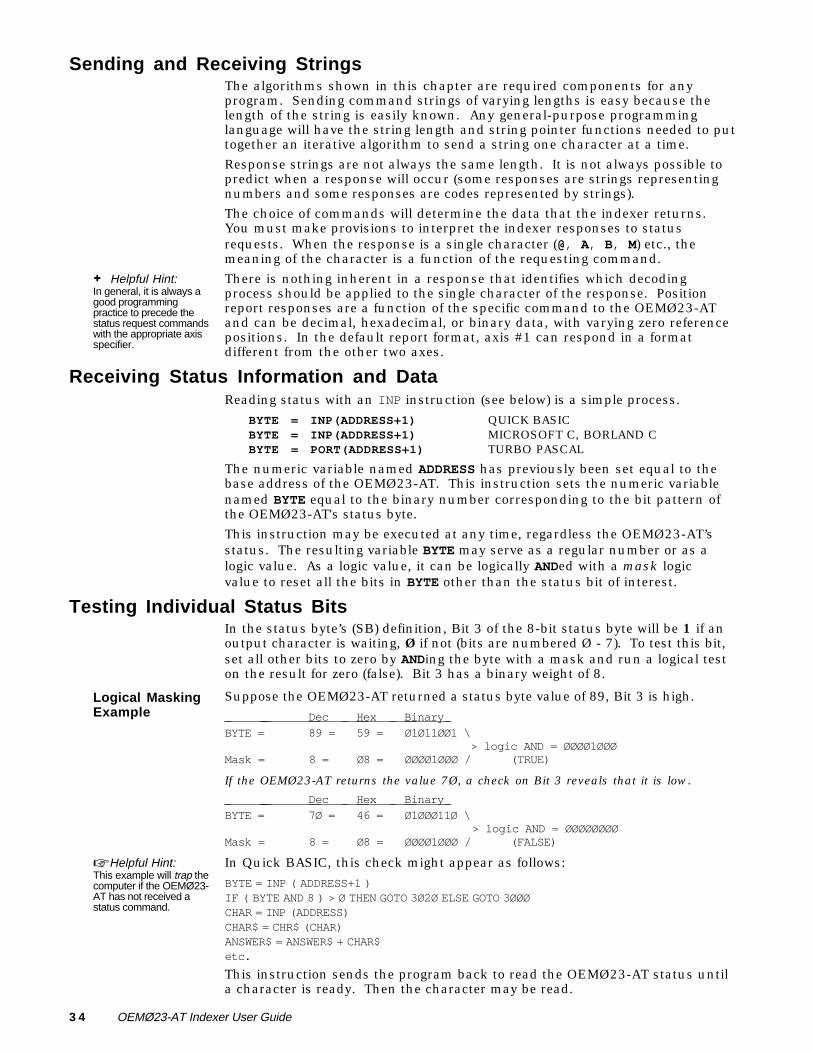
Testing Individual Status BitsIn the status byte’s (SB) definition, Bit 3 of the 8-bit status byte will be 1 if anoutput character is waiting, Ø if not (bits are numbered Ø - 7). To test this bit,set all other bits to zero by ANDing the byte with a mask and run a logical teston the result for zero (false). Bit 3 has a binary weight of 8.
Logical MaskingExample
Suppose the OEMØ23-AT returned a status byte value of 89, Bit 3 is high.
Dec Hex Binary
BYTE = 89 = 59 = Ø1Ø11ØØ1 \ > logic AND = ØØØØ1ØØØ
Mask = 8 = Ø8 = ØØØØ1ØØØ / (TRUE)
If the OEMØ23-AT returns the value 7Ø, a check on Bit 3 reveals that it is low.
Dec Hex Binary
BYTE = 7Ø = 46 = Ø1ØØØ11Ø \ > logic AND = ØØØØØØØØ
Mask = 8 = Ø8 = ØØØØ1ØØØ / (FALSE)
☞ Helpful Hint:This example will trap thecomputer if the OEMØ23-AT has not received astatus command.
In Quick BASIC, this check might appear as follows:
BYTE = INP ( ADDRESS+1 )IF ( BYTE AND 8 ) > Ø THEN GOTO 3Ø2Ø ELSE GOTO 3ØØØCHAR = INP (ADDRESS)CHAR$ = CHR$ (CHAR)ANSWER$ = ANSWER$ + CHAR$etc.
This instruction sends the program back to read the OEMØ23-AT status untila character is ready. Then the character may be read.
Chapter ➃ Application Design 3 5
Sending Control Information and DataTo write bytes to the OEMØ23-AT, use the following instructions.
OUT ADDRESS, ALPHA BASICOUTPORTB(ADDRESS, ALPHA); TURBO COUTP(ADDRESS, ALPHA); MICROSOFT CPORT[ADDRESS]: = ALPHA; PASCAL
Resetting the OEMØ23-ATThe following are step-by-step procedures for writing your own subroutinesfor resetting the OEMØ23-AT:
➀ Write 64 Hex to the Control Port (Board Address +1).➁ Read the Status Port (Board Address +1) until the status byte and 20 Hex > 0.➂ Write 40 Hex to the Control Byte (Board Address +1).➃ Write 60 Hex to the Control Byte (Board Address +1).➄ Read the Status Port (Board Address +1) until the status byte and 7F Hex = 17 Hex.➅ Write 20 Hex to the Control Port (Board Address +1).➆ Write 60 Hex to the Control Port (Board Address +1).
ReadingCharacters Fromthe OEMØ23-AT
Use the following procedure to read characters from the OEMØ23-AT:
➀ Initialize the ASCII variable to null (Ø).➁ Read the Status Port (Board Address +1) until Status Byte and 8 Hex >0.➂ Read the Data Port (Board Address) in to the ASCII variable.➃ Write EØ Hex to the Control Port (Board Address +1).➄ Read the Status Port (Board Address +1) until the status byte and 8 Hex = 0.➅ Write 60 Hex to the Control Port (Board Address +1).
WritingCharacters to aOEMØ23-AT
Use the following procedure to write characters to the OEMØ23-AT:➀ Convert the character to ASCII. This may not be necessary in some programming
languages such as C (except for axes in Binary Input Data Streaming mode).➁ Read the Status Port (Board Address +1) until the Status Byte AND 10 Hex > 0.➂ Write the ASCII character to the Data Port (Board Address+1).➃ Write 70 Hex to the Control Port (Board Address +1).➄ Read the Status Port (Board Address +1) until the Status Byte AND 10 Hex = 0.➅ Write 60 Hex to the Control Byte (Board Address +1).
Program ExamplesThe support disk files below provide read, write, and reset routines.
❏ MOVE.BAS (written in Quick BASIC)❏ OEM23P.PAS (written in PASCAL)❏ OEM23C.C (written in C)
These files provide the foundation from which you can design a motioncontrol program for the OEMØ23-AT. The following are examples of how touse these files to create your own OEMØ23-AT program.
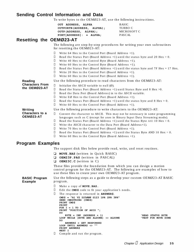
BASIC ProgramExample
Use the following steps as a guide to develop your custom OEMØ23-AT BASICprogram.
➀ Make a copy of MOVE.BAS.➁ Edit the CMD$ code to fit your application’s needs.➂ The response is returned in ANSWER$.
CMD$ = "A1 V2 D25ØØØ G123 1PR 2PR 3PR"SEND CMDSTRING (CMD$)PRINT CMD$PRINTFOR I = 1 TO 3PRINT "POSITION OF AXIS ";DO
BYTE = INP (ADDRESS + 1) 'READ STATUS BYTELOOP WHILE (BYTE AND ALDONE) <> ALDONE 'TEST FOR MOVE DONEDO
ANSWER$ = GET RESPONSE$LOOP UNTIL ANSWER$ <> ""PRINT ANSWER$NEXT I
➄ Compile and run the program.
3 6 OEMØ23-AT Indexer User Guide
C ProgramExample
Use the following steps as a guide to develop your custom OEMØ23-AT Cprogram.➀ Make a copy of OEM23C.C.➁ Edit the main program of the copied file.➂ To send a command, place the X language in message (message = A1Ø V1Ø
D25ØØØ G). Then make a call to procedure writecmd (message).➃ To get a response from the OEMØ23-AT, use procedure readanswer (answer).
The response is returned in answer.➄ Example: main() {
char *message,*answer;answer="";initialize(); /*resets OEMØ23-AT*/message = " 1PR ";writecmd (message);readanswer (answer);printf (answer);} /* end of main*/
➅ Compile and run the program.
PASCAL ProgramExample
Use the following steps as a guide to develop your custom OEMØ23-ATPASCAL program.
➀ Make a copy of OEM23P.PAS.➁ Edit the main program of the copied file.➂ To send a command, place the X language commands in message (cmd = A1Ø
V1Ø D25ØØØ G). Then make a call to procedure writecmd (768,cmd) where768 is the OEMØ23-AT board address.
➃ To get a response from the OEMØ23-AT, use procedure readanswer(768,answer). The response is returned in answer.
➄ Example: beginanswer:='';Initialize (768);cmd:=' A1Ø V1Ø D25ØØØ G PR ';Writecmd (768,cmd);while answer='' do Readanswer (768,answer);writeln (answer);End
➅ Compile and run the program.
Chapter ➃ Application Design 3 7
Special Modes of OperationThis section discusses special modes of operation for the OEMØ23-AT. Thesespecial modes include the following:
❏ Using multiple OEMØ23-ATs with one computer❏ X-Y linear interpolation❏ Using interrupts
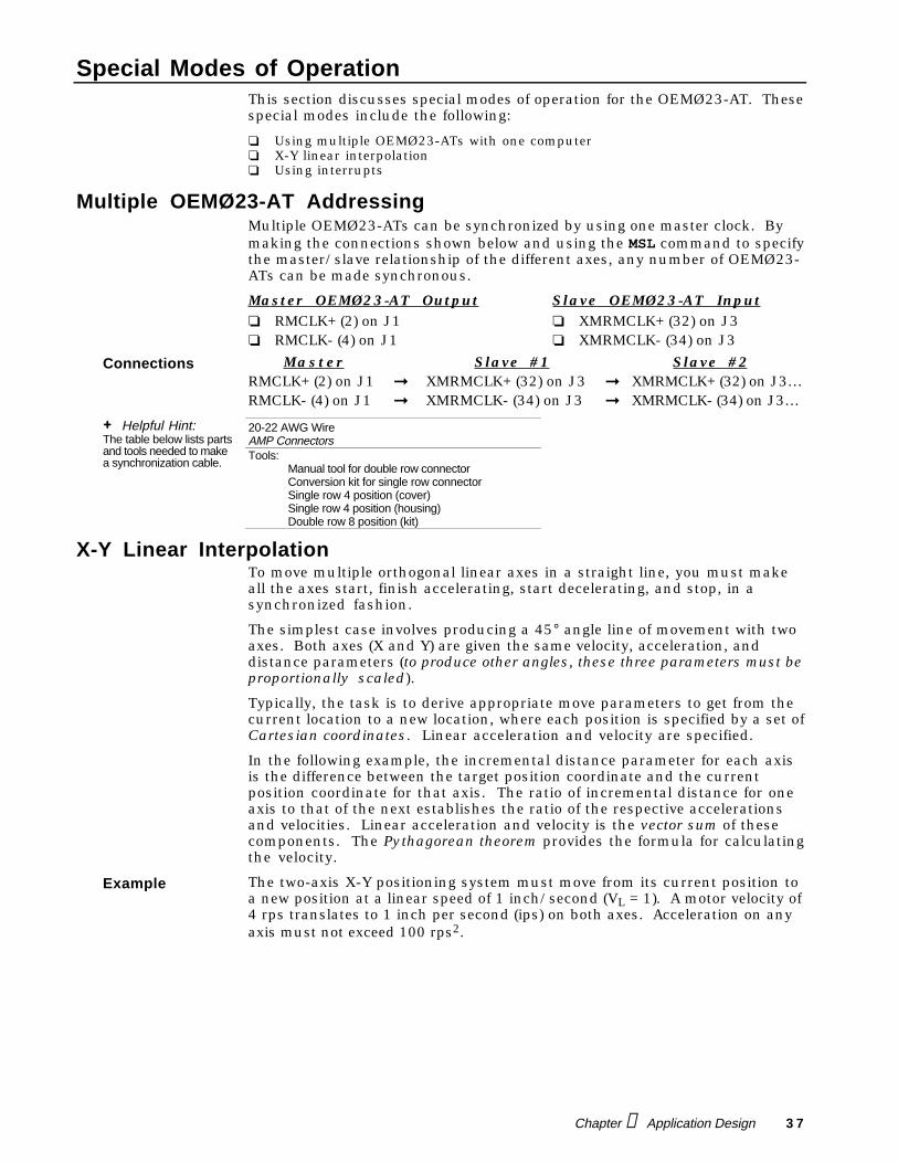
Multiple OEMØ23-AT AddressingMultiple OEMØ23-ATs can be synchronized by using one master clock. Bymaking the connections shown below and using the MSL command to specifythe master/slave relationship of the different axes, any number of OEMØ23-ATs can be made synchronous.
Master OEMØ23-AT Output Slave OEMØ23-AT Input❏ RMCLK+ (2) on J1 ❏ XMRMCLK+ (32) on J3❏ RMCLK- (4) on J1 ❏ XMRMCLK- (34) on J3
Connections Master Slave #1 Slave #2RMCLK+ (2) on J1 ➞ XMRMCLK+ (32) on J3 ➞ XMRMCLK+ (32) on J3…RMCLK- (4) on J1 ➞ XMRMCLK- (34) on J3 ➞ XMRMCLK- (34) on J3…
+ Helpful Hint:The table below lists partsand tools needed to makea synchronization cable.
20-22 AWG WireAMP ConnectorsTools:
Manual tool for double row connectorConversion kit for single row connectorSingle row 4 position (cover)Single row 4 position (housing)Double row 8 position (kit)
X-Y Linear InterpolationTo move multiple orthogonal linear axes in a straight line, you must makeall the axes start, finish accelerating, start decelerating, and stop, in asynchronized fashion.
The simplest case involves producing a 45° angle line of movement with twoaxes. Both axes (X and Y) are given the same velocity, acceleration, anddistance parameters (to produce other angles, these three parameters must beproportionally scaled).
Typically, the task is to derive appropriate move parameters to get from thecurrent location to a new location, where each position is specified by a set ofCartesian coordinates. Linear acceleration and velocity are specified.
In the following example, the incremental distance parameter for each axisis the difference between the target position coordinate and the currentposition coordinate for that axis. The ratio of incremental distance for oneaxis to that of the next establishes the ratio of the respective accelerationsand velocities. Linear acceleration and velocity is the vector sum of thesecomponents. The Pythagorean theorem provides the formula for calculatingthe velocity.
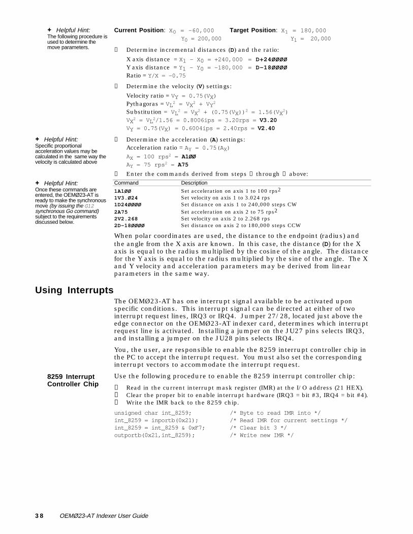
Example The two-axis X-Y positioning system must move from its current position toa new position at a linear speed of 1 inch/second (VL = 1). A motor velocity of4 rps translates to 1 inch per second (ips) on both axes. Acceleration on anyaxis must not exceed 100 rps2.
3 8 OEMØ23-AT Indexer User Guide
+ Helpful Hint:The following procedure isused to determine themove parameters.
Current Position: X0 = -60,000 Target Position: X1 = 180,000Y0 = 200,000 Y1 = 20,000
➀ Determine incremental distances (D) and the ratio:
X axis distance = X1 - X0 = +240,000 = D+24ØØØØ
Y axis distance = Y1 - Y0 = -180,000 = D-18ØØØØ
Ratio = Y/X = -0.75
➁ Determine the velocity (V) settings:
Velocity ratio = VY = 0.75(VX)Pythagoras = VL2 = VX2 + VY2
Substitution = VL2 = VX2 + (0.75(VX))2 = 1.56(VX2)VX
2 = VL2/1.56 = 0.8006ips = 3.20rps = V3.20
VY = 0.75(VX) = 0.6004ips = 2.40rps = V2.40
+ Helpful Hint:Specific proportionalacceleration values may becalculated in the same way thevelocity is calculated above
➂ Determine the acceleration (A) settings:Acceleration ratio = AY = 0.75(AX)AX = 100 rps
2 = A1ØØ
AY = 75 rps2 = A75
➃ Enter the commands derived from steps ➀ through ➂ above:
+ Helpful Hint:Once these commands areentered, the OEMØ23-AT isready to make the synchronousmove (by issuing the G12synchronous Go command)subject to the requirementsdiscussed below.
Command Description
1A1ØØ Set acceleration on axis 1 to 100 rps2
1V3.Ø24 Set velocity on axis 1 to 3.024 rps1D24ØØØØ Set distance on axis 1 to 240,000 steps CW2A75 Set acceleration on axis 2 to 75 rps2
2V2.268 Set velocity on axis 2 to 2.268 rps2D-18ØØØØ Set distance on axis 2 to 180,000 steps CCW
When polar coordinates are used, the distance to the endpoint (radius) andthe angle from the X axis are known. In this case, the distance (D) for the Xaxis is equal to the radius multiplied by the cosine of the angle. The distancefor the Y axis is equal to the radius multiplied by the sine of the angle. The Xand Y velocity and acceleration parameters may be derived from linearparameters in the same way.
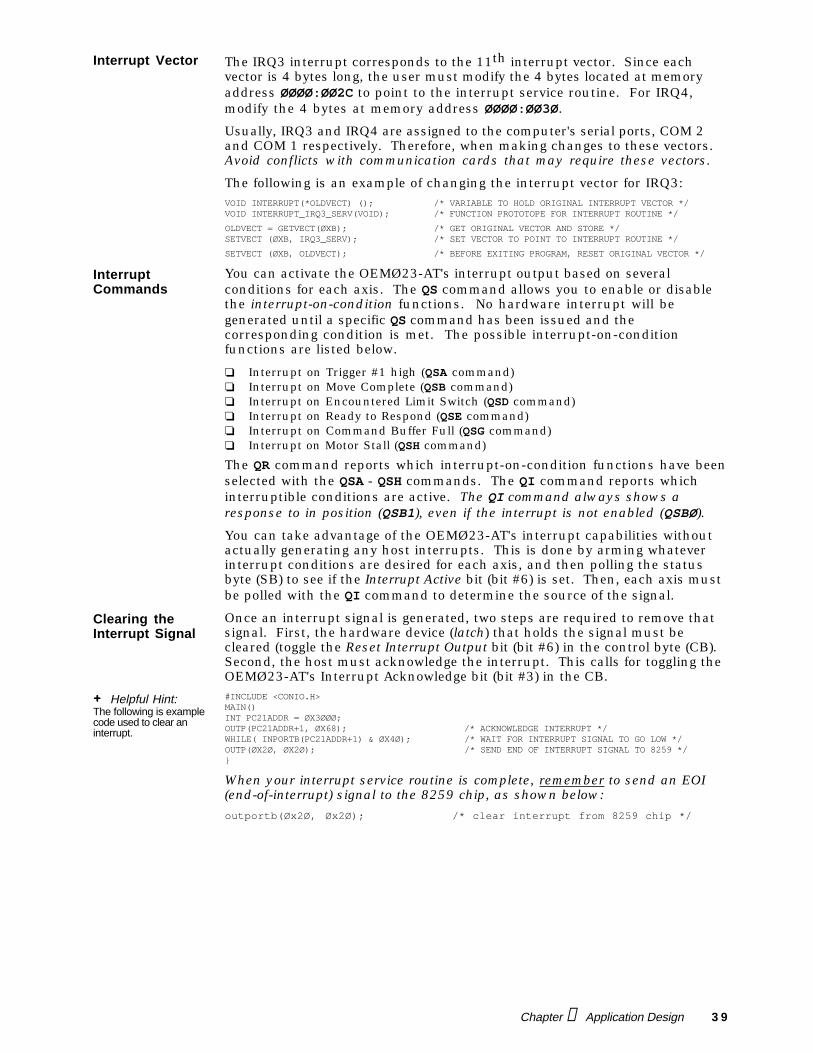
Using InterruptsThe OEMØ23-AT has one interrupt signal available to be activated uponspecific conditions. This interrupt signal can be directed at either of twointerrupt request lines, IRQ3 or IRQ4. Jumper 27/28, located just above theedge connector on the OEMØ23-AT indexer card, determines which interruptrequest line is activated. Installing a jumper on the JU27 pins selects IRQ3,and installing a jumper on the JU28 pins selects IRQ4.
You, the user, are responsible to enable the 8259 interrupt controller chip inthe PC to accept the interrupt request. You must also set the correspondinginterrupt vectors to accommodate the interrupt request.
8259 InterruptController Chip
Use the following procedure to enable the 8259 interrupt controller chip:
➀ Read in the current interrupt mask register (IMR) at the I/O address (21 HEX).➁ Clear the proper bit to enable interrupt hardware (IRQ3 = bit #3, IRQ4 = bit #4).➂ Write the IMR back to the 8259 chip.
unsigned char int_8259; /* Byte to read IMR into */int_8259 = inportb(0x21); /* Read IMR for current settings */int_8259 = int_8259 & 0xF7; /* Clear bit 3 */outportb(0x21,int_8259); /* Write new IMR */
Chapter ➃ Application Design 3 9
Interrupt Vector The IRQ3 interrupt corresponds to the 11th interrupt vector. Since eachvector is 4 bytes long, the user must modify the 4 bytes located at memoryaddress ØØØØ:ØØ2C to point to the interrupt service routine. For IRQ4,modify the 4 bytes at memory address ØØØØ:ØØ3Ø.
Usually, IRQ3 and IRQ4 are assigned to the computer's serial ports, COM 2and COM 1 respectively. Therefore, when making changes to these vectors.Avoid conflicts with communication cards that may require these vectors.
The following is an example of changing the interrupt vector for IRQ3:VOID INTERRUPT(*OLDVECT) (); /* VARIABLE TO HOLD ORIGINAL INTERRUPT VECTOR */VOID INTERRUPT_IRQ3_SERV(VOID); /* FUNCTION PROTOTOPE FOR INTERRUPT ROUTINE */
OLDVECT = GETVECT(ØXB); /* GET ORIGINAL VECTOR AND STORE */SETVECT (ØXB, IRQ3_SERV); /* SET VECTOR TO POINT TO INTERRUPT ROUTINE */
SETVECT (ØXB, OLDVECT); /* BEFORE EXITING PROGRAM, RESET ORIGINAL VECTOR */
InterruptCommands
You can activate the OEMØ23-AT's interrupt output based on severalconditions for each axis. The QS command allows you to enable or disablethe interrupt-on-condition functions. No hardware interrupt will begenerated until a specific QS command has been issued and thecorresponding condition is met. The possible interrupt-on-conditionfunctions are listed below.
❏ Interrupt on Trigger #1 high (QSA command)❏ Interrupt on Move Complete (QSB command)❏ Interrupt on Encountered Limit Switch (QSD command)❏ Interrupt on Ready to Respond (QSE command)❏ Interrupt on Command Buffer Full (QSG command)❏ Interrupt on Motor Stall (QSH command)
The QR command reports which interrupt-on-condition functions have beenselected with the QSA - QSH commands. The QI command reports whichinterruptible conditions are active. The QI command always shows aresponse to in position (QSB1), even if the interrupt is not enabled (QSBØ).
You can take advantage of the OEMØ23-AT's interrupt capabilities withoutactually generating any host interrupts. This is done by arming whateverinterrupt conditions are desired for each axis, and then polling the statusbyte (SB) to see if the Interrupt Active bit (bit #6) is set. Then, each axis mustbe polled with the QI command to determine the source of the signal.
Clearing theInterrupt Signal
Once an interrupt signal is generated, two steps are required to remove thatsignal. First, the hardware device (latch) that holds the signal must becleared (toggle the Reset Interrupt Output bit (bit #6) in the control byte (CB).Second, the host must acknowledge the interrupt. This calls for toggling theOEMØ23-AT's Interrupt Acknowledge bit (bit #3) in the CB.
+ Helpful Hint:The following is examplecode used to clear aninterrupt.
#INCLUDE <CONIO.H>MAIN()INT PC21ADDR = ØX3ØØØ;OUTP(PC21ADDR+1, ØX68); /* ACKNOWLEDGE INTERRUPT */WHILE( INPORTB(PC21ADDR+1) & ØX4Ø); /* WAIT FOR INTERRUPT SIGNAL TO GO LOW */OUTP(ØX2Ø, ØX2Ø); /* SEND END OF INTERRUPT SIGNAL TO 8259 */}
When your interrupt service routine is complete, remember to send an EOI(end-of-interrupt) signal to the 8259 chip, as shown below:
outportb(Øx2Ø, Øx2Ø); /* clear interrupt from 8259 chip */