Embed Size (px)
Citation preview
http://support.automation.siemens.com/WW/view/en/23939668
Application description 01/2014
Closed-loop torque control and load distribution MICROMASTER 440
Warranty and liability
Closed-loop torque control and load distribution Entry-ID: 23939668, V1.2, 01/2014 2
Sie
men
s A
G 2
014
All
right
s re
serv
ed
Warranty and liability
Note The Application Examples are not binding and do not claim to be complete regarding the circuits shown, equipping and any eventuality. The Application Examples do not represent customer-specific solutions. They are only intended to provide support for typical applications. You are responsible for ensuring that the described products are used correctly. These application examples do not relieve you of the responsibility to use safe practices in application, installation, operation and maintenance. When using these Application Examples, you recognize that we cannot be made liable for any damage/claims beyond the liability clause described. We reserve the right to make changes to these Application Examples at any time without prior notice. If there are any deviations between the recommendations provided in these application examples and other Siemens publications – e.g. Catalogs – the contents of the other documents have priority.
We do not accept any liability for the information contained in this document.
Any claims against us – based on whatever legal reason – resulting from the use of the examples, information, programs, engineering and performance data etc., described in this Application Example shall be excluded. Such an exclusion shall not apply in the case of mandatory liability, e.g. under the German Product Liability Act (“Produkthaftungsgesetz”), in case of intent, gross negligence, or injury of life, body or health, guarantee for the quality of a product, fraudulent concealment of a deficiency or breach of a condition which goes to the root of the contract (“wesentliche Vertragspflichten”). The damages for a breach of a substantial contractual obligation are, however, limited to the foreseeable damage, typical for the type of contract, except in the event of intent or gross negligence or injury to life, body or health. The above provisions do not imply a change of the burden of proof to your detriment. Any form of duplication or distribution of these Application Examples or excerpts hereof is prohibited without the expressed consent of Siemens Industry Sector.
Security informa-tion
Siemens provides products and solutions with industrial security functions that support the secure operation of plants, solutions, machines, equipment and/or networks. They are important components in a holistic industrial security concept. With this in mind, Siemens’ products and solutions undergo continuous development. Siemens recommends strongly that you regularly check for product updates.
For the secure operation of Siemens products and solutions, it is necessary to take suitable preventive action (e.g. cell protection concept) and integrate each component into a holistic, state-of-the-art industrial security concept. Third-party products that may be in use should also be considered. For more information about industrial security, visit http://www.siemens.com/industrialsecurity.
To stay informed about product updates as they occur, sign up for a product-specific newsletter. For more information, visit http://support.automation.siemens.com.
Table of contents
Closed-loop torque control and load distribution Entry-ID: 23939668, V1.2, 01/2014 3
Sie
men
s A
G 2
014
All
right
s re
serv
ed
Table of contents Warranty and liability ............................................................................................... 2 Preposition ............................................................................................................... 4 1 Closed-loop torque control ............................................................................ 5
1.1 Applications ....................................................................................... 5 1.2 Operating behavior ............................................................................ 5 1.3 Circuit versions .................................................................................. 5 1.3.1 Closed-loop torque control with an encoder ....................................... 5 1.3.2 Closed-loop torque control without an encoder ................................... 8 1.3.3 Off command ................................................................................... 10 1.3.4 Maximum speed .............................................................................. 11 1.3.5 Limits............................................................................................... 11 1.3.6 Changing over to closed-loop torque control .................................... 14 1.3.7 Closed-loop control by limiting the torque ......................................... 16 1.4 Torque display ................................................................................. 19 1.5 Speed monitoring ............................................................................ 20
2 Pre-control .................................................................................................... 21 3 Closed-loop load distribution control.......................................................... 23
3.1 Problems associated with group drives ............................................ 23 3.2 Load distribution using individual drives ........................................... 24 3.2.1 Droop .............................................................................................. 24 3.2.2 Master / slave drive with speed encoder .......................................... 25 3.2.3 Master/slave drive without speed encoder........................................ 27
4 Related literature .......................................................................................... 28 5 Contact.......................................................................................................... 28 6 History .......................................................................................................... 28
1 Closed-loop torque control 1.1 Applications
Closed-loop torque control and load distribution Entry-ID: 23939668, V1.2, 01/2014 4
Cop
yrig
ht
Sie
men
s A
G 2
014
All
right
s re
serv
ed
Preposition Aim of the application
This application description was generated in order to provide users with a better understanding of closed-loop torque control and load distribution.
Core contents of this application The following core points are handled in this application:
Closed-loop torque control Load distribution
Scope This application does not include any specific description for
Winders and unwinders
1 Closed-loop torque control 1.1 Applications
Closed-loop torque control and load distribution Entry-ID: 23939668, V1.2, 01/2014 5
Cop
yrig
ht
Sie
men
s A
G 2
014
All
right
s re
serv
ed
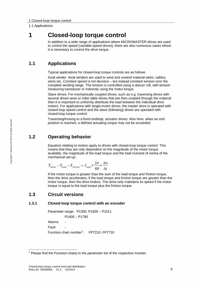
1 Closed-loop torque control In addition to a wide range of applications where MICROMASTER drives are used to control the speed (variable-speed drives), there are also numerous cases where it is necessary to control the drive torque.
1.1 Applications
Typical applications for closed-loop torque controls are as follows Axial winder: Axial winders are used to wind and unwind material webs, cables, wires etc. Constant speed is not decisive – but instead constant tension over the complete winding range. The tension is controlled using a dancer roll, with tension measuring transducer or indirectly using the motor torque. Slave drives: For mechanically coupled drives, such as e.g. traversing drives with several driven axes or roller table drives that are then coupled through the material then it is important to uniformly distribute the load between the individual drive motors. For applications with single-motor drives, the master drive is operated with closed-loop speed control and the slave (following) drives are operated with closed-loop torque control. Traversing/moving to a fixed endstop, actuator drives: Also here, when an end position is reached, a defined actuating torque may not be exceeded.
1.2 Operating behavior
Equation relating to motion apply to drives with closed-loop torque control. This means that they are only dependent on the magnitude of the motor torque available, the magnitude of the load torque and the total moment of inertia of the mechanical set-up.
tnJTTT totalfrictionloadmotor 60
2
If the motor torque is greater than the sum of the load torque and friction torque, then the drive accelerates; if the load torque and friction torque are greater than the motor torque, then the drive brakes. The drive only maintains its speed if the motor torque is equal to the load torque plus the friction torque.
1.3 Circuit versions
1.3.1 Closed-loop torque control with an encoder
Parameter range: P1300, P1500 – P1511 P1400 – P1780 Alarms - Fault - Function chart number1: FP7210, FP7710
1 Please find the Function charts in the parameter list of the respective Inverter
1 Closed-loop torque control 1.3 Circuit versions
Closed-loop torque control and load distribution Entry-ID: 23939668, V1.2, 01/2014 6
Cop
yrig
ht
Sie
men
s A
G 2
014
All
right
s re
serv
ed
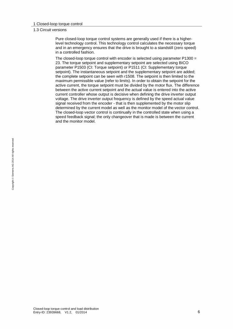
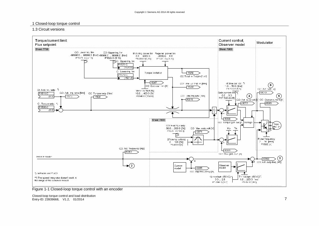
Pure closed-loop torque control systems are generally used if there is a higher-level technology control. This technology control calculates the necessary torque and in an emergency ensures that the drive is brought to a standstill (zero speed) in a controlled fashion. The closed-loop torque control with encoder is selected using parameter P1300 = 23. The torque setpoint and supplementary setpoint are selected using BICO parameter P1503 (CI: Torque setpoint) or P1511 (CI: Supplementary torque setpoint). The instantaneous setpoint and the supplementary setpoint are added; the complete setpoint can be seen with r1508. The setpoint is then limited to the maximum permissible value (refer to limits). In order to obtain the setpoint for the active current, the torque setpoint must be divided by the motor flux. The difference between the active current setpoint and the actual value is entered into the active current controller whose output is decisive when defining the drive inverter output voltage. The drive inverter output frequency is defined by the speed actual value signal received from the encoder - that is then supplemented by the motor slip determined by the current model as well as the monitor model of the vector control. The closed-loop vector control is continually in the controlled state when using a speed feedback signal; the only changeover that is made is between the current and the monitor model.
1 Closed-loop torque control 1.3 Circuit versions
Closed-loop torque control and load distribution Entry-ID: 23939668, V1.2, 01/2014 7
Copyright Siemens AG 2014 All rights reserved
Figure 1-1 Closed-loop torque control with an encoder
1 Closed-loop torque control 1.3 Circuit versions
Closed-loop torque control and load distribution Entry-ID: 23939668, V1.2, 01/2014 8
Cop
yrig
ht
Sie
men
s A
G 2
014
All
right
s re
serv
ed
1.3.2 Closed-loop torque control without an encoder
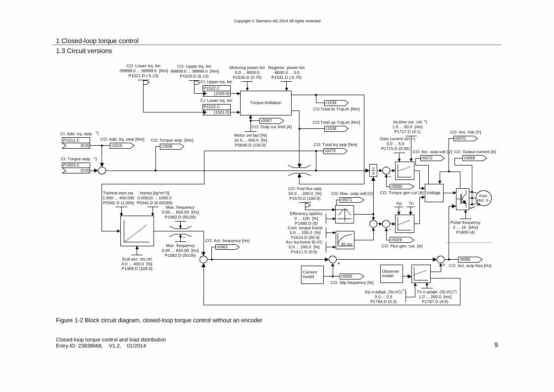
Parameter range: P1300, P1500 – P1511 P1400 – P1780 Alarms - Fault - Function chart number2: FP7200, FP7700 Closed-loop torque control without encoder is selected using parameter P1300 = 22. The torque setpoint and supplementary setpoint are in turn selected using BICO parameter P1503 (CI: Torque setpoint) and P1511 (CI: Supplementary torque setpoint). The torque setpoint and the supplementary setpoint are added; the complete setpoint can be seen with r1508. The setpoint is then limited to the maximum permissible value (refer to limits). In order to obtain the setpoint for the active current, the torque setpoint must be divided by the machine flux. The difference between the active current setpoint and the actual value is entered into the active current controller whose output is decisive when defining the drive inverter output voltage. Contrary to closed-loop torque control with encoder the speed actual value is now calculated in the monitor model.
2 Please find the Function charts in the parameter list of the respective Inverter
1 Closed-loop torque control 1.3 Circuit versions
Closed-loop torque control and load distribution Entry-ID: 23939668, V1.2, 01/2014 9
Copyright Siemens AG 2014 All rights reserved
CI: Add. trq. setp
(0:0)P1511.C
CI: Torque setp.
(0:0)P1503.C
r1508 CO: Torque setp. [Nm]
Inertia [kg*m^2]0.00010 ... 1000.0 P0341.D (0.00180)
Scal acc. trq ctrl0.0 ... 400.0 [%]P1499.D (100.0)
r0063 CO: Act. frequency [Hz]
*)
*)
CO: Upper trq. lim-99999.0 ... 99999.0 [Nm]
P1520.D (5.13)
CO: Lower trq. lim-99999.0 ... 99999.0 [Nm]
P1521.D (-5.13)CI: Upper trq. lim
(1520:0)P1522.C
CI: Lower trq. lim
(1521:0)P1523.C
Torque limitation
r1538 CO:Total up TrqLim [Nm]
r0079 CO: Total trq setp [Nm]
xy
Efficiency optimiz0 ... 100 [%]P1580.D (0)
CO: Fval flux setp50.0 ... 200.0 [%]P1570.D (100.0)
r1539 CO:Total lw TrqLim [Nm]
Motor ovl fact [%]10.0 ... 400.0 [%]P0640.D (150.0)
Motoring power lim0.0 ... 8000.0
P1530.D (0.75)
Regener. power lim-8000.0 ... 0.0
P1531.D (-0.75)
Cont. torque boost0.0 ... 200.0 [%]P1610.D (50.0)
Acc trq boost SLVC0.0 ... 200.0 [%]P1611.D (0.0)
30 ms
r0071 CO: Max. outp.volt [V]
r1515 CO: Add. trq. setp [Nm]
r0067 CO: Outp cur limit [A]
Tot/mot inert.rat.1.000 ... 400.000 P0342.D (1.000)
Max. frequency0.00 ... 650.00 [Hz]
P1082.D (50.00)
Max. frequency0.00 ... 650.00 [Hz]
P1082.D (50.00)
–
Asyc.Mot. 3~
r0030 CO: Torque gen.cur [A]
Gain current ctrl.0.0 ... 5.0
P1715.D (0.25)
Int.time cur. ctrl1.0 ... 50.0 [ms]P1717.D (4.1)
Kp Tn
–
–
r0029 CO: Flux gen. cur. [A]
Voltage
Pulse frequency2 ... 16 [kHz]
P1800 (4)
r0068 CO: Output current [A]
*)
*) r0070 CO: Act. Vdc [V]
r0072 CO: Act. outp.volt [V]
+ +
r0065 CO: Slip frequency [%]
r0066 CO: Act. outp freq [Hz]
Kp n-adapt. (SLVC)0.0 ... 2.5
P1764.D (0.2)
Tn n-adapt. (SLVC)1.0 ... 200.0 [ms]
P1767.D (4.0)
Observer model
Current model
*)*)
Figure 1-2 Block circuit diagram, closed-loop torque control without an encoder
1 Closed-loop torque control 1.3 Circuit versions
Closed-loop torque control and load distribution Entry-ID: 23939668, V1.2, 01/2014 10
Cop
yrig
ht
Sie
men
s A
G 2
014
All
right
s re
serv
ed
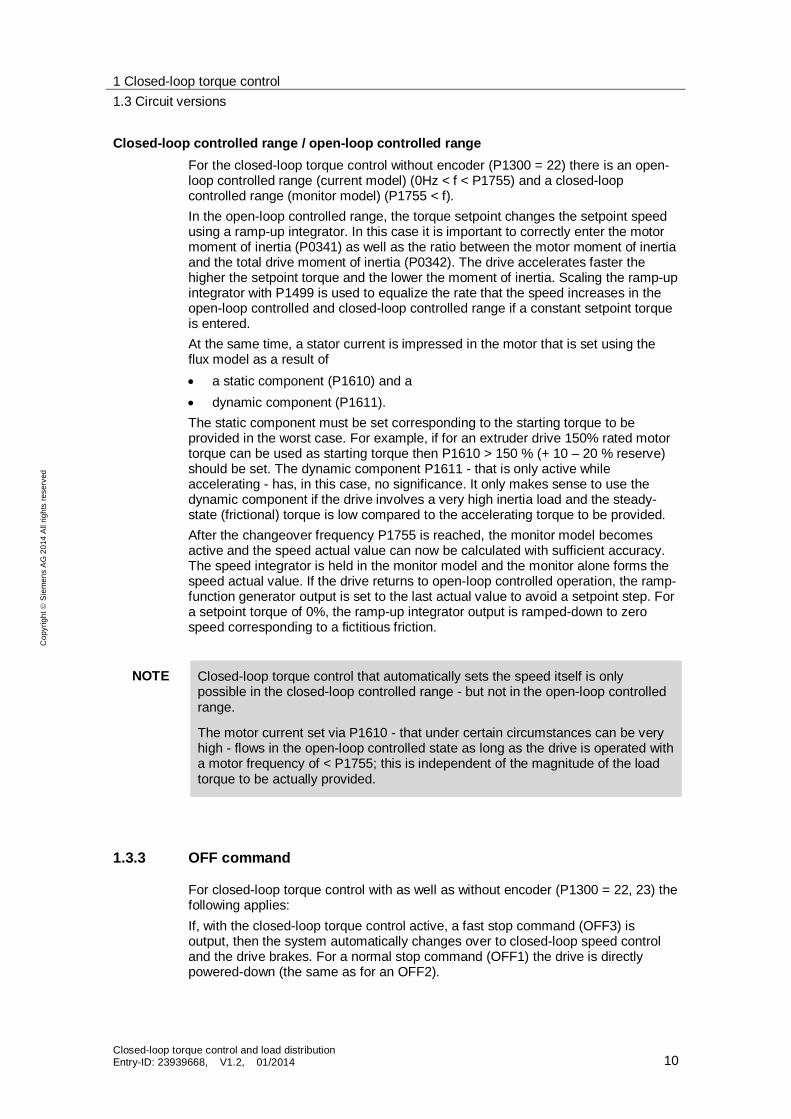
Closed-loop controlled range / open-loop controlled range For the closed-loop torque control without encoder (P1300 = 22) there is an open-loop controlled range (current model) (0Hz < f < P1755) and a closed-loop controlled range (monitor model) (P1755 < f). In the open-loop controlled range, the torque setpoint changes the setpoint speed using a ramp-up integrator. In this case it is important to correctly enter the motor moment of inertia (P0341) as well as the ratio between the motor moment of inertia and the total drive moment of inertia (P0342). The drive accelerates faster the higher the setpoint torque and the lower the moment of inertia. Scaling the ramp-up integrator with P1499 is used to equalize the rate that the speed increases in the open-loop controlled and closed-loop controlled range if a constant setpoint torque is entered. At the same time, a stator current is impressed in the motor that is set using the flux model as a result of a static component (P1610) and a dynamic component (P1611).
The static component must be set corresponding to the starting torque to be provided in the worst case. For example, if for an extruder drive 150% rated motor torque can be used as starting torque then P1610 > 150 % (+ 10 – 20 % reserve) should be set. The dynamic component P1611 - that is only active while accelerating - has, in this case, no significance. It only makes sense to use the dynamic component if the drive involves a very high inertia load and the steady-state (frictional) torque is low compared to the accelerating torque to be provided. After the changeover frequency P1755 is reached, the monitor model becomes active and the speed actual value can now be calculated with sufficient accuracy. The speed integrator is held in the monitor model and the monitor alone forms the speed actual value. If the drive returns to open-loop controlled operation, the ramp-function generator output is set to the last actual value to avoid a setpoint step. For a setpoint torque of 0%, the ramp-up integrator output is ramped-down to zero speed corresponding to a fictitious friction.
NOTE Closed-loop torque control that automatically sets the speed itself is only possible in the closed-loop controlled range - but not in the open-loop controlled range.
The motor current set via P1610 - that under certain circumstances can be very high - flows in the open-loop controlled state as long as the drive is operated with a motor frequency of < P1755; this is independent of the magnitude of the load torque to be actually provided.
1.3.3 OFF command
For closed-loop torque control with as well as without encoder (P1300 = 22, 23) the following applies: If, with the closed-loop torque control active, a fast stop command (OFF3) is output, then the system automatically changes over to closed-loop speed control and the drive brakes. For a normal stop command (OFF1) the drive is directly powered-down (the same as for an OFF2).
1 Closed-loop torque control 1.3 Circuit versions
Closed-loop torque control and load distribution Entry-ID: 23939668, V1.2, 01/2014 11
Cop
yrig
ht
Sie
men
s A
G 2
014
All
right
s re
serv
ed
1.3.4 Maximum speed
Closed-loop torque control systems without the possibility to changing over to closed-loop speed control have the problem that when a torque is specified and the load is disconnected, the drive accelerates along the torque limit. In order to prevent mechanical damage when this happens - above the maximum speed (plus 3 %), a speed limiting controller reduces the torque limits in order to prevent the drive from continuing to accelerate.
1.3.5 Limits
The complete setpoint for the torque is limited to maximum permissible values using quite a complex circuit.
1 Closed-loop torque control 1.3 Circuit versions
Closed-loop torque control and load distribution Entry-ID: 23939668, V1.2, 01/2014 12
Copyright Siemens AG 2014 All rights reserved
to current control
CO/BO: Stat 2 ctrl
r1407r1407
CO/BO: Stat 2 ctrlr1407r1407
r0079 CO: Total trq setp [Nm]
.8
.9
aand FP7500
FP7900
r1508 CO: Torque setp.
CI: Torque setp.
(0:0)P1503.C
**) r1538
r1539
CO/BO: Stat 2 ctrl
r1407r1407
CO/BO: Stat 2 ctrlr1407r1407
.8
.9
r1515 CO: Add. trq. setpCI: Add. trq. setp
(0:0)P1511.C
**)
From flux setpoint
Scal. low trq. lim-400.0 ... 400.0 [%]
P1525.D (100.0)
r1527 CO: Lower trq. lim
r1526 CO: Upper trq. lim
-1
MIN
MAXr1539
CO:Total lw TrqLim
r1538 CO:Total up TrqLim+
Speed limitation controller
(only for torque control)
Imax
CI: Upper trq. lim
(1520:0)P1522.C
CI: Lower trq. lim
(1521:0)P1523.C
Motor stall protection
CO: Upper trq. lim-99999.0 ... 99999.0 [Nm]
P1520.D (5.13)
CO: Lower trq. lim-99999.0 ... 99999.0 [Nm]
P1521.D (-5.13)
*)
Id
Motor ovl fact [%]10.0 ... 400.0 [%]P0640.D (150.0)
Rated mot. current0.01 ... 10000.00 [A]
P0305.D (3.25)
Motor temperaturInverter temperaturi2t inverter r0067
CO: Outp cur limit
act. frequency
Power limitation
Motoring power lim0.0 ... 8000.0
P1530.D (0.75)
Regener. power lim-8000.0 ... 0.0
P1531.D (-0.75)M [Nm] =
f 2 [kW] P 1000
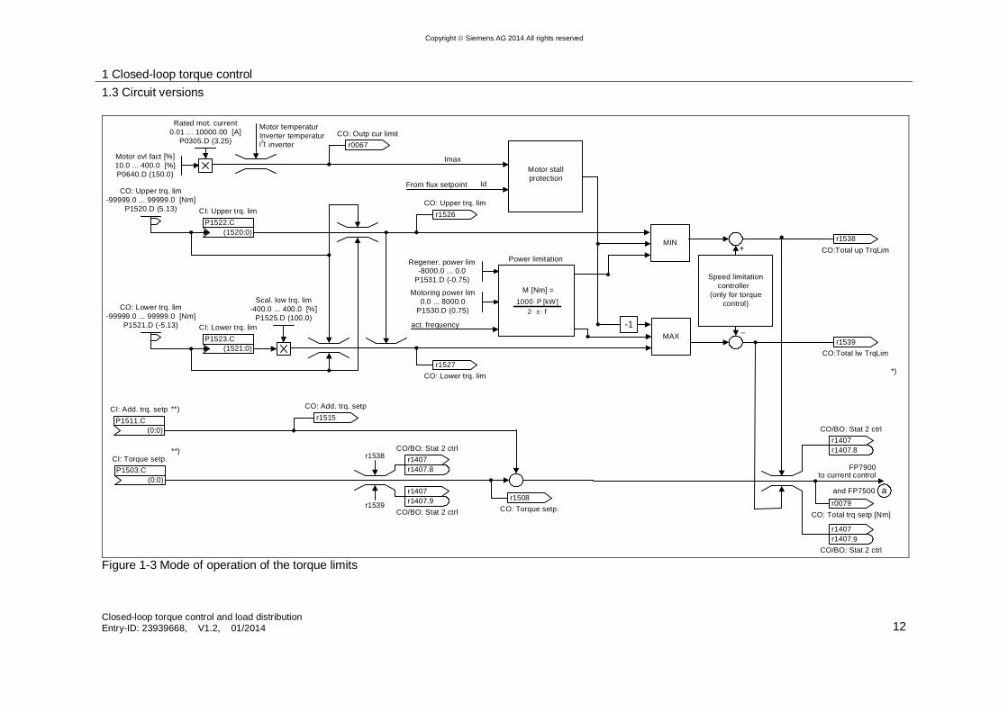
Figure 1-3 Mode of operation of the torque limits
1 Closed-loop torque control 1.3 Circuit versions
Closed-loop torque control and load distribution Entry-ID: 23939668, V1.2, 01/2014 13
Cop
yrig
ht
Sie
men
s A
G 2
014
All
right
s re
serv
ed
Torque limits To start, the permanently programmable torque limits P1520 and P1521 are entered into the limit circuit; these can be set to a maximum of 400% of the rated motor torque. Further, variable torque limits with BICO interconnection (e.g. via an analog input) can be entered using P1522 and P1523.
Current limiting Several measured values from the motor and drive inverter are entered into the current limiting. The current limit for the motor is set as overload limit in P0640 (referred to P0305) and displayed in r0067. When the overload protection function intervenes (I2t), r0067 is reduced with respect to P0640 – assuming that this response was selected in P0610. Using the actual field-generating current component Isd,set the current limit is converted into the limit of the torque-generating current component Isq,set. The torque limit is obtained by multiplying this with the actual rotor flux.
)(I * I T 22maxmax sqmax sdsetI
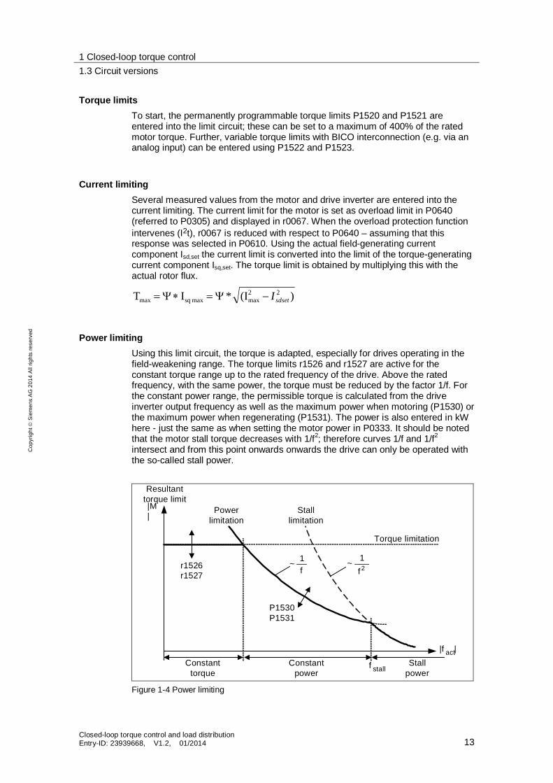
Power limiting Using this limit circuit, the torque is adapted, especially for drives operating in the field-weakening range. The torque limits r1526 and r1527 are active for the constant torque range up to the rated frequency of the drive. Above the rated frequency, with the same power, the torque must be reduced by the factor 1/f. For the constant power range, the permissible torque is calculated from the drive inverter output frequency as well as the maximum power when motoring (P1530) or the maximum power when regenerating (P1531). The power is also entered in kW here - just the same as when setting the motor power in P0333. It should be noted that the motor stall torque decreases with 1/f2; therefore curves 1/f and 1/f2 intersect and from this point onwards onwards the drive can only be operated with the so-called stall power.
f 1 ~
Torque limitation
Resultanttorque limit
Powerlimitation
|f act
r1526r1527
Stalllimitation
P1530P1531
f 1 ~2
Constanttorque
f stallConstant
power
|
|M|
Stallpower
Figure 1-4 Power limiting

1 Closed-loop torque control 1.3 Circuit versions
Closed-loop torque control and load distribution Entry-ID: 23939668, V1.2, 01/2014 14
Cop
yrig
ht
Sie
men
s A
G 2
014
All
right
s re
serv
ed
An arithmetic circuit determines the maximum and minimum permitted torque limits between the programmable torque limit values and the limit values that are obtained from the motor stall protection, the motor/drive inverter temperature monitoring and the power limiting. Speed limiting is also active. A minimum is used from the different limits. This minimum is cyclically computed in the drive inverter and is displayed in parameters r1538 and r1539. If the torque setpoint is limited in the drive inverter, then this is displayed using the following diagnostic parameters r1407 bit 08 upper torque limit active r1407 bit 09 lower torque limit active
NOTE In addition, using current limiting, the maximum torque that can be achieved with the motor is influenced. If the torque limits are increased this only results in increased torque if a higher current can also flow. To achieve this, it may be necessary to adapt the current limit.
1.3.6 Changing over to closed-loop torque control
Parameter range: P1300, P1500 – P1511 P1400 – P1780 Alarms - Fault - Function chart number3: FP7700, FP7710 For closed-loop speed control with encoder (P1300 = 21) and without encoder (P1300 = 20) it is possible to changeover to closed-loop torque control (slave drive) using BICO parameter P1501. This changeover can be controlled both by external events as well as events in the drive inverter itself (e.g. the load torque monitoring function). The torque setpoint and supplementary torque setpoint can be selected using parameter P1500 as well as also using BICO parameter P1503 (CI: Torque setpoint) or P1511 (CI: Supplementary torque setpoint). The supplementary torque is effective for closed-loop torque and for closed-loop speed control. As a result of this feature, a pre-control torque can be implemented for the speed control using the supplementary torque setpoint. When changing over from closed-loop torque control to closed-loop speed control, the integral component of speed controller r1482 is set so that a torque step does not occur in the control. At the same time, the output of the ramp-function generator r1170 is set to the speed actual value so that a step does not occur in the P component of the speed controller.
3 Please find the Function charts in the parameter list of the respective Inverter
1 Closed-loop torque control 1.3 Circuit versions
Closed-loop torque control and load distribution Entry-ID: 23939668, V1.2, 01/2014 15
Cop
yrig
ht
Sie
men
s A
G 2
014
All
right
s re
serv
ed
–
Torquesetpoint
Droop
Act. frequency
– r1538 r1538
r1539 r1539
0
CI: Torque setp.
(0:0)P1503.C
(0:0)
BI:-> torque ctrl.P1501.C
CI: Add. trq. setp
(0:0)P1511.C
Pre-control
Freq. setpoint
PI Speed
controller
SLVC:VC:
P1452P1442
P1470P1460
P1472P1462
Ti
Kp Tn
T i Kp Tn
*)
*) nur aktiv, wenn die Vorsteuerung aktiviert ist (P1496 > 0)
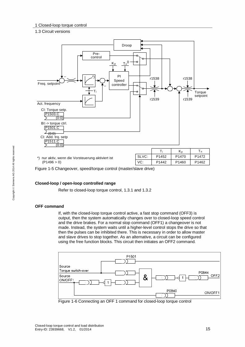
Figure 1-5 Changeover, speed/torque control (master/slave drive)
Closed-loop / open-loop controlled range Refer to closed-loop torque control, 1.3.1 and 1.3.2
OFF command If, with the closed-loop torque control active, a fast stop command (OFF3) is output, then the system automatically changes over to closed-loop speed control and the drive brakes. For a normal stop command (OFF1) a changeover is not made. Instead, the system waits until a higher-level control stops the drive so that then the pulses can be inhibited there. This is necessary in order to allow master and slave drives to stop together. As an alternative, a circuit can be configured using the free function blocks. This circuit then initiates an OFF2 command.
Figure 1-6 Connecting an OFF 1 command for closed-loop torque control
1 Closed-loop torque control 1.3 Circuit versions
Closed-loop torque control and load distribution Entry-ID: 23939668, V1.2, 01/2014 16
Cop
yrig
ht
Sie
men
s A
G 2
014
All
right
s re
serv
ed
Maximum speed Refer to the maximum speed 1.3.4
Limits Refer to the limits 1.3.5
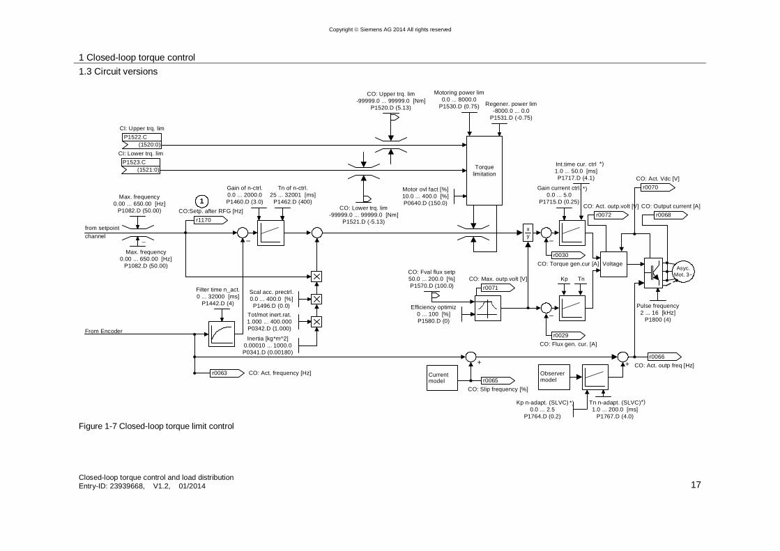
1.3.7 Closed-loop control by limiting the torque
Parameter range: P1300, P1500 – P1511 P1400 – P1780 Alarms - Fault - Function chart number4: FP7200, FP7210, FP7700, FP7710 A torque limit control function is used if the drive predominantly operates in the speed-controlled range but must provide defined torques in specific operating states. For closed-loop torque control using the limits, the drive is operated with sensorless closed-loop speed control SLVC (P1300 = 20) or closed-loop speed control VC with encoder (P1300 = 21). The speed controller must be over-controlled (the speed setpoint is multiplied by a factor) so that there is a sufficient voltage range (stroke) available at the speed controller output. The overcontrol value is selected so that the speed increase when the load torque is withdrawn is not too high - on the other hand the controller remains at the limits even during dynamic operations. A defined torque limit can now be specified by connecting parameters P1522 and P1523 to fixed setpoints, analog inputs, interfaces. This circuit has the advantage that when the load is withdrawn the drive accelerates as a maximum up to the setpoint speed plus the overcontrol. Further, calibrating the speed actual value is completely uncritical as long as the error does not reach the overcontrol level. This is an advantage that should not be underestimated - e.g. for rolls that are subject to continuous wear.
4 Please find the Function charts in the parameter list of the respective Inverter
1 Closed-loop torque control 1.3 Circuit versions
Closed-loop torque control and load distribution Entry-ID: 23939668, V1.2, 01/2014 17
Copyright Siemens AG 2014 All rights reserved
From Encoder
from setpoint channel –
Asyc.Mot. 3~
+ +
1Max. frequency0.00 ... 650.00 [Hz]
P1082.D (50.00)
Max. frequency0.00 ... 650.00 [Hz]
P1082.D (50.00)
r1170 CO:Setp. after RFG [Hz]
Scal acc. prectrl.0.0 ... 400.0 [%]P1496.D (0.0)
Inertia [kg*m^2]0.00010 ... 1000.0 P0341.D (0.00180)
Tot/mot inert.rat.1.000 ... 400.000 P0342.D (1.000)
Gain of n-ctrl.0.0 ... 2000.0 P1460.D (3.0)
Tn of n-ctrl.25 ... 32001 [ms]
P1462.D (400)
Filter time n_act.0 ... 32000 [ms]
P1442.D (4)
r0063 CO: Act. frequency [Hz]
CO: Upper trq. lim-99999.0 ... 99999.0 [Nm]
P1520.D (5.13)
CO: Lower trq. lim-99999.0 ... 99999.0 [Nm]
P1521.D (-5.13)
Torque limitation
xy
Efficiency optimiz0 ... 100 [%]P1580.D (0)
CO: Fval flux setp50.0 ... 200.0 [%]P1570.D (100.0)
Motor ovl fact [%]10.0 ... 400.0 [%]P0640.D (150.0)
Motoring power lim0.0 ... 8000.0
P1530.D (0.75) Regener. power lim-8000.0 ... 0.0
P1531.D (-0.75)
r0030 CO: Torque gen.cur [A]
Gain current ctrl.0.0 ... 5.0
P1715.D (0.25)
Int.time cur. ctrl1.0 ... 50.0 [ms]P1717.D (4.1)
Kp Tn
–
–
r0029 CO: Flux gen. cur. [A]
Voltage
r0065 CO: Slip frequency [%]
r0066 CO: Act. outp freq [Hz]
Kp n-adapt. (SLVC)0.0 ... 2.5
P1764.D (0.2)
Tn n-adapt. (SLVC)1.0 ... 200.0 [ms]
P1767.D (4.0)
Observer model
Current model
Pulse frequency2 ... 16 [kHz]
P1800 (4)
r0068 CO: Output current [A]
*)
*)
*)
*)
r0071 CO: Max. outp.volt [V]
r0070 CO: Act. Vdc [V]
r0072 CO: Act. outp.volt [V]
CI: Upper trq. lim
(1520:0)P1522.C
CI: Lower trq. lim
(1521:0)P1523.C
Figure 1-7 Closed-loop torque limit control
1 Closed-loop torque control 1.3 Circuit versions
Closed-loop torque control and load distribution Entry-ID: 23939668, V1.2, 01/2014 18
Cop
yrig
ht
Sie
men
s A
G 2
014
All
right
s re
serv
ed
OFF command The OFF1 and OFF3 commands are still available as the drive still continuous to operate in the closed-loop speed controlled mode.
Maximum speed If the torque limit is increased to the maximum, then the drive goes back into the closed-loop speed controlled mode. This prevents the drive from accelerating in an uncontrolled fashion.
Limits Refer to the closed-loop torque control 1.3.4
1 Closed-loop torque control 1.4 Torque display
Closed-loop torque control and load distribution Entry-ID: 23939668, V1.2, 01/2014 19
Cop
yrig
ht
Sie
men
s A
G 2
014
All
right
s re
serv
ed
1.4 Torque display
Depending on the control type, the displayed torque differs.
Closed-loop vector control For vector control types, the torque is obtained from
sqrdpR
mmotor IZ
LLT
23
with Tmotor: Motor torque Lm: Magnetizing inductance LR: Rotor inductance Zp: Pole pair number rd: Rotor flux Isq: Torque-generating current It must be clearly observed that the torque that is obtained is the so-called electrical torque - the mechanical torque output at the shaft is less than the electrical torque by the electrical losses and the friction.
v/f characteristics When using the v/f characteristics, the active current Isq corresponding to the torque is not calculated by the vector transformation, it is obtained as follows:
EIRIV
I SSSsq
2cos
with Isq: Torque-generating current V: Terminal voltage IS: Stator current RS: Stator resistance E: Counter-voltage By defining several quantities, this display is not so accurate over the control range as the display for closed-loop vector control.
1 Closed-loop torque control 1.5 Speed monitoring
Closed-loop torque control and load distribution Entry-ID: 23939668, V1.2, 01/2014 20
Cop
yrig
ht
Sie
men
s A
G 2
014
All
right
s re
serv
ed
1.5 Speed monitoring
For closed-loop torque control systems, normally, the torque to be controlled is important and not so much the speed. This means that if a closed-loop torque control or closed-loop torque limiting is used based on closed-loop speed control the speed encoder monitoring should be disabled using P0492 = 0 to avoid Fault F0090. The encoder monitoring function checks whether the speed setpoint and actual value move within a specific window - if this window is violated Fault F0090 is output.
2 Pre-control
Closed-loop torque control and load distribution Entry-ID: 23939668, V1.2, 01/2014 21
Cop
yrig
ht
Sie
men
s A
G 2
014
All
right
s re
serv
ed
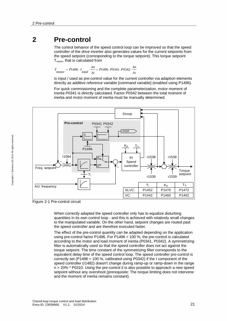
2 Pre-control The control behavior of the speed control loop can be improved so that the speed controller of the drive inverter also generates values for the current setpoints from the speed setpoint (corresponding to the torque setpoint). This torque setpoint Tmotor, that is calculated from
t
nPPP
t
ntotal
JPmotor
T 0342034114961496
is input / used as pre-control value for the current controller via adaption elements directly as additive reference variable [command variable] (enabled using P1496). For quick commissioning and the complete parameterization, motor moment of inertia P0341 is directly calculated. Factor P0342 between the total moment of inertia and motor moment of inertia must be manually determined.
–Torquesetpoint
Droop
–r1538 r1538
r1539 r1539
PI Speed
controller
r1518
=0
>0
P0341 P0342
P1496
Pre-control
SLVC:VC:
P1452P1442
P1470P1460
P1472P1462
T i
Kp Tn
T i Kp Tn
Freq. setpoint
Act. frequency
r1084
Figure 2-1 Pre-control circuit When correctly adapted the speed controller only has to equalize disturbing quantities in its own control loop - and this is achieved with relatively small changes to the manipulated variable. On the other hand, setpoint changes are routed past the speed controller and are therefore executed faster. The effect of the pre-control quantity can be adapted depending on the application using pre-control factor P1496. For P1496 = 100 %, the pre-control is calculated according to the motor and load moment of inertia (P0341, P0342). A symmetrizing filter is automatically used so that the speed controller does not act against the torque setpoint. The time constant of the symmetrizing filter corresponds to the equivalent delay time of the speed control loop. The speed controller pre-control is correctly set (P1496 = 100 %, calibrated using P0342) if the I component of the speed controller (r1482) doesn't change during ramp-up or ramp-down in the range n > 20% * P0310. Using the pre-control it is also possible to approach a new speed setpoint without any overshoot (prerequisite: The torque limiting does not intervene and the moment of inertia remains constant).
2 Pre-control
Closed-loop torque control and load distribution Entry-ID: 23939668, V1.2, 01/2014 22
Cop
yrig
ht
Sie
men
s A
G 2
014
All
right
s re
serv
ed
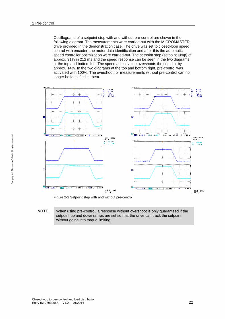
Oscillograms of a setpoint step with and without pre-control are shown in the following diagram. The measurements were carried-out with the MICROMASTER drive provided in the demonstration case. The drive was set to closed-loop speed control with encoder, the motor data identification and after this the automatic speed controller optimization were carried-out. The setpoint step (setpoint jump) of approx. 31% in 212 ms and the speed response can be seen in the two diagrams at the top and bottom left. The speed actual value overshoots the setpoint by approx. 14%. In the two diagrams at the top and bottom right, pre-control was activated with 100%. The overshoot for measurements without pre-control can no longer be identified in them.
Figure 2-2 Setpoint step with and without pre-control
NOTE When using pre-control, a response without overshoot is only guaranteed if the setpoint up and down ramps are set so that the drive can track the setpoint without going into torque limiting.
3 Closed-loop load distribution control 3.1 Problems associated with group drives
Closed-loop torque control and load distribution Entry-ID: 23939668, V1.2, 01/2014 23
Cop
yrig
ht
Sie
men
s A
G 2
014
All
right
s re
serv
ed
3 Closed-loop load distribution control For mechanically coupled drives, such as e.g. traversing drives with several driven axes, or roller table drives that are coupled through a material web it is important that the load is evenly distributed across the individual drive motors. Depending on the particular application, this can be realized using a group drive with one drive inverter or using individual drives each equipped with its own drive inverter.
3.1 Problems associated with group drives
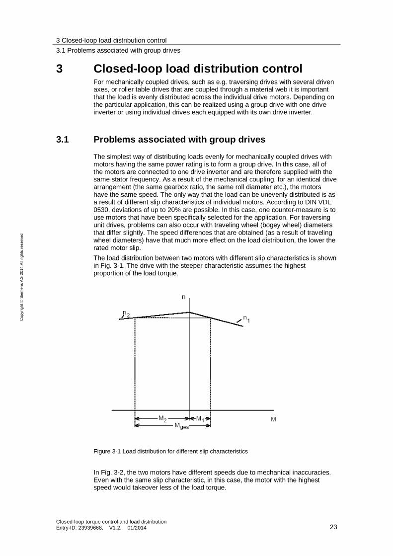
The simplest way of distributing loads evenly for mechanically coupled drives with motors having the same power rating is to form a group drive. In this case, all of the motors are connected to one drive inverter and are therefore supplied with the same stator frequency. As a result of the mechanical coupling, for an identical drive arrangement (the same gearbox ratio, the same roll diameter etc.), the motors have the same speed. The only way that the load can be unevenly distributed is as a result of different slip characteristics of individual motors. According to DIN VDE 0530, deviations of up to 20% are possible. In this case, one counter-measure is to use motors that have been specifically selected for the application. For traversing unit drives, problems can also occur with traveling wheel (bogey wheel) diameters that differ slightly. The speed differences that are obtained (as a result of traveling wheel diameters) have that much more effect on the load distribution, the lower the rated motor slip. The load distribution between two motors with different slip characteristics is shown in Fig. 3-1. The drive with the steeper characteristic assumes the highest proportion of the load torque.
Figure 3-1 Load distribution for different slip characteristics
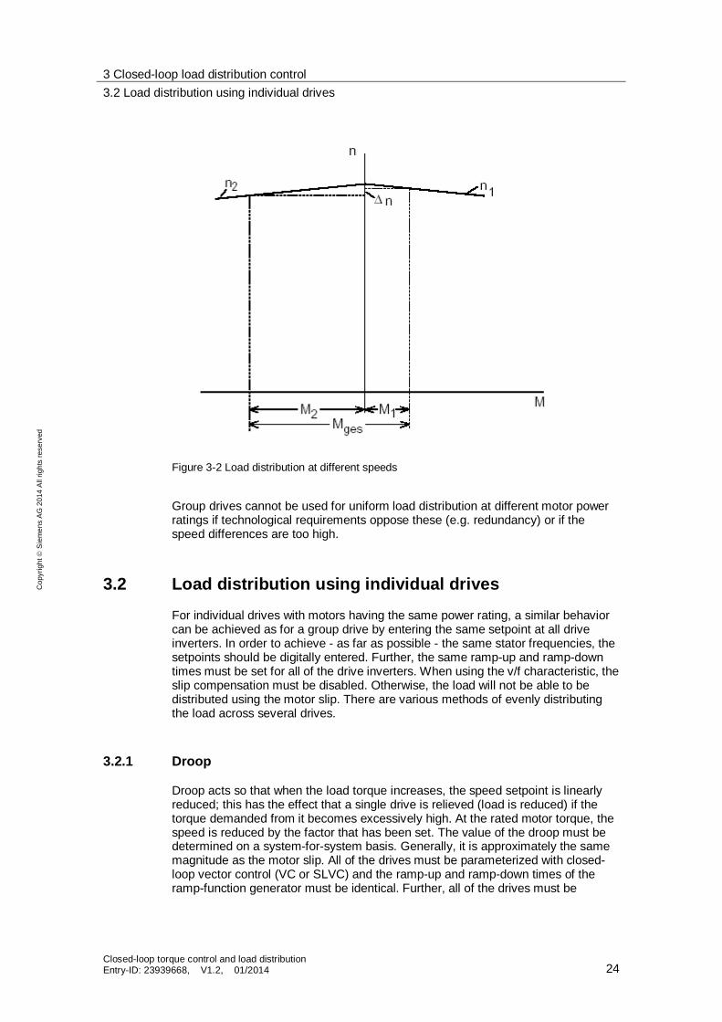
In Fig. 3-2, the two motors have different speeds due to mechanical inaccuracies. Even with the same slip characteristic, in this case, the motor with the highest speed would takeover less of the load torque.
3 Closed-loop load distribution control 3.2 Load distribution using individual drives
Closed-loop torque control and load distribution Entry-ID: 23939668, V1.2, 01/2014 24
Cop
yrig
ht
Sie
men
s A
G 2
014
All
right
s re
serv
ed
Figure 3-2 Load distribution at different speeds
Group drives cannot be used for uniform load distribution at different motor power ratings if technological requirements oppose these (e.g. redundancy) or if the speed differences are too high.
3.2 Load distribution using individual drives
For individual drives with motors having the same power rating, a similar behavior can be achieved as for a group drive by entering the same setpoint at all drive inverters. In order to achieve - as far as possible - the same stator frequencies, the setpoints should be digitally entered. Further, the same ramp-up and ramp-down times must be set for all of the drive inverters. When using the v/f characteristic, the slip compensation must be disabled. Otherwise, the load will not be able to be distributed using the motor slip. There are various methods of evenly distributing the load across several drives.
3.2.1 Droop
Droop acts so that when the load torque increases, the speed setpoint is linearly reduced; this has the effect that a single drive is relieved (load is reduced) if the torque demanded from it becomes excessively high. At the rated motor torque, the speed is reduced by the factor that has been set. The value of the droop must be determined on a system-for-system basis. Generally, it is approximately the same magnitude as the motor slip. All of the drives must be parameterized with closed-loop vector control (VC or SLVC) and the ramp-up and ramp-down times of the ramp-function generator must be identical. Further, all of the drives must be
3 Closed-loop load distribution control 3.2 Load distribution using individual drives
Closed-loop torque control and load distribution Entry-ID: 23939668, V1.2, 01/2014 25
Cop
yrig
ht
Sie
men
s A
G 2
014
All
right
s re
serv
ed
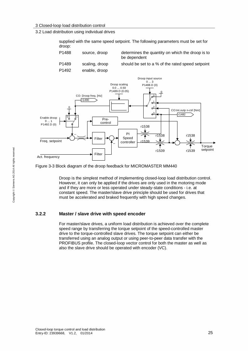
supplied with the same speed setpoint. The following parameters must be set for droop: P1488 source, droop determines the quantity on which the droop is to
be dependent P1489 scaling, droop should be set to a % of the rated speed setpoint P1492 enable, droop
–Torquesetpoint
Act. frequency
–Filter
r1538
r1539
Pre-control
Freq. setpoint
Filter
PI Speed
controller
r1482 CO:Int.outp n-ctrl [Nm]
Droop input source0 ... 3
P1488.D (0)Droop scaling0.0 ... 0.50
P1489.D (0.05)0
2
1
3
0
0 1
r1490 CO: Droop freq. [Hz]
0
Enable droop0 ... 1
P1492.D (0) r1538
r1539
r1538
r1539
Figure 3-3 Block diagram of the droop feedback for MICROMASTER MM440
Droop is the simplest method of implementing closed-loop load distribution control. However, it can only be applied if the drives are only used in the motoring mode and if they are more or less operated under steady-state conditions - i.e. at constant speed. The master/slave drive principle should be used for drives that must be accelerated and braked frequently with high speed changes.
3.2.2 Master / slave drive with speed encoder
For master/slave drives, a uniform load distribution is achieved over the complete speed range by transferring the torque setpoint of the speed-controlled master drive to the torque-controlled slave drives. The torque setpoint can either be transferred using an analog output or using peer-to-peer data transfer with the PROFIBUS profile. The closed-loop vector control for both the master as well as also the slave drive should be operated with encoder (VC).
3 Closed-loop load distribution control 3.2 Load distribution using individual drives
Closed-loop torque control and load distribution Entry-ID: 23939668, V1.2, 01/2014 26
Cop
yrig
ht
Sie
men
s A
G 2
014
All
right
s re
serv
ed
– Torquesetpoint
Act. frequency
r1538
r1539
(0:0)
BI:-> torque ctrl.P1501.C
Freq. setpoint PI Speed
controller
T i
Kp Tn
r0079 CO: Total trq setp [Nm]
– Torquesetpoint
Act. frequency
r1538
r1539
(0:0)
BI:-> torque ctrl.P1501.C
Freq. setpoint PI Speed
controller
T i
Kp Tn
CI: Torque setp.
(0:0)P1503.C
Drive 2
Drive 1
Freq. setpoint
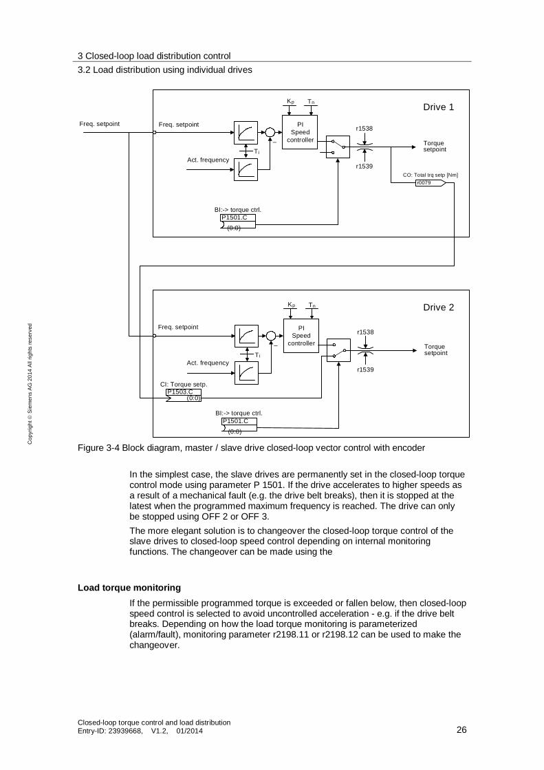
Figure 3-4 Block diagram, master / slave drive closed-loop vector control with encoder
In the simplest case, the slave drives are permanently set in the closed-loop torque control mode using parameter P 1501. If the drive accelerates to higher speeds as a result of a mechanical fault (e.g. the drive belt breaks), then it is stopped at the latest when the programmed maximum frequency is reached. The drive can only be stopped using OFF 2 or OFF 3. The more elegant solution is to changeover the closed-loop torque control of the slave drives to closed-loop speed control depending on internal monitoring functions. The changeover can be made using the
Load torque monitoring If the permissible programmed torque is exceeded or fallen below, then closed-loop speed control is selected to avoid uncontrolled acceleration - e.g. if the drive belt breaks. Depending on how the load torque monitoring is parameterized (alarm/fault), monitoring parameter r2198.11 or r2198.12 can be used to make the changeover.
3 Closed-loop load distribution control 3.2 Load distribution using individual drives
Closed-loop torque control and load distribution Entry-ID: 23939668, V1.2, 01/2014 27
Cop
yrig
ht
Sie
men
s A
G 2
014
All
right
s re
serv
ed
3.2.3 Master/slave drive without speed encoder
If a speed encoder is not used, disturbance-free, smooth operation of the closed-loop load distribution control over the complete speed control range is only conditionally guaranteed. Under certain circumstances here, when starting from standstill, the subsequent control must be first inhibited and can only be enabled from approx. 10 % of the speed. Monitoring parameter r1751.2 can be used to implement this; it is at a low signal level (SLVC open-loop controlled) below the changeover threshold parameterized using P1755 and is at a high (SLVC closed-loop controlled) above the changeover threshold.
4 Related literature
Closed-loop torque control and load distribution Entry-ID: 23939668, V1.2, 01/2014 28
Sie
men
s A
G 2
014
All
right
s re
serv
ed
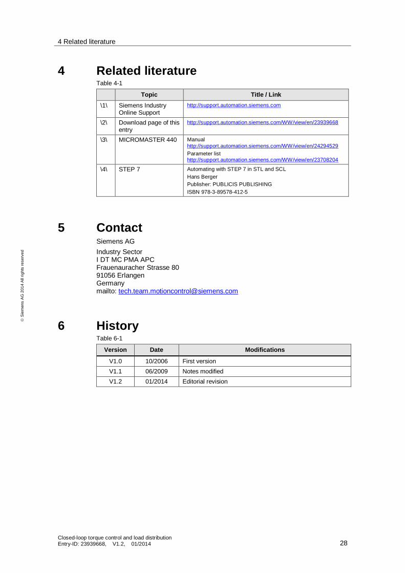
4 Related literature Table 4-1
Topic Title / Link \1\ Siemens Industry
Online Support http://support.automation.siemens.com
\2\ Download page of this entry
http://support.automation.siemens.com/WW/view/en/23939668
\3\ MICROMASTER 440 Manual http://support.automation.siemens.com/WW/view/en/24294529 Parameter list http://support.automation.siemens.com/WW/view/en/23708204
\4\ STEP 7 Automating with STEP 7 in STL and SCL Hans Berger Publisher: PUBLICIS PUBLISHING ISBN 978-3-89578-412-5
5 Contact Siemens AG Industry Sector I DT MC PMA APC Frauenauracher Strasse 80 91056 Erlangen Germany mailto: [email protected]
6 History Table 6-1
Version Date Modifications
V1.0 10/2006 First version V1.1 06/2009 Notes modified V1.2 01/2014 Editorial revision