Embed Size (px)
Citation preview

https://support.industry.siemens.com/cs/ww/en/view/51345318
Application description 01/2017
SIMOTION
Print Standard
Segment GRAVURE Application handbook
Warranty and liability
Print Standard Segment Gravure SIOS-ID: 51345318, V3.0.0, 01/2017 2
Cop
yri
gh
t
Sie
me
ns A
G 2
01
7 A
ll ri
gh
ts r
ese
rve
d
Warranty and liability
Note The Application Examples are not binding and do not claim to be complete regarding the circuits shown, equipping and any eventuality. The Application Examples do not represent customer-specific solutions. They are only intended to provide support for typical applications. You are responsible for ensuring that the described products are used correctly. These Application Examples do not relieve you of the responsibility to use safe practices in application, installation, operation and maintenance. When using these Application Examples, you recognize that we cannot be made liable for any damage/claims beyond the liability clause described. We reserve the right to make changes to these Application Examples at any time without prior notice. If there are any deviations between the recommendations provided in these Application Examples and other Siemens publications – e.g. Catalogs – the contents of the other documents have priority.
We do not accept any liability for the information contained in this document. Any claims against us – based on whatever legal reason – resulting from the use of the examples, information, programs, engineering and performance data etc., described in this Application Example shall be excluded. Such an exclusion shall not apply in the case of mandatory liability, e.g. under the German Product Liability Act (“Produkthaftungsgesetz”), in case of intent, gross negligence, or injury of life, body or health, guarantee for the quality of a product, fraudulent concealment of a deficiency or breach of a condition which goes to the root of the contract (“wesentliche Vertragspflichten”). The damages for a breach of a substantial contractual obligation are, however, limited to the foreseeable damage, typical for the type of contract, except in the event of intent or gross negligence or injury to life, body or health. The above provisions do not imply a change of the burden of proof to your detriment. Any form of duplication or distribution of these Application Examples or excerpts hereof is prohibited without the expressed consent of the Siemens AG.
Security informa-tion
Siemens provides products and solutions with industrial security functions that support the secure operation of plants, systems, machines and networks. In order to protect plants, systems, machines and networks against cyber threats, it is necessary to implement – and continuously maintain – a holistic, state-of-the-art industrial security concept. Siemens’ products and solutions only form one element of such a concept. Customer is responsible to prevent unauthorized access to its plants, systems, machines and networks. Systems, machines and components should only be connected to the enterprise network or the internet if and to the extent necessary and with appropriate security measures (e.g. use of firewalls and network segmentation) in place. Additionally, Siemens’ guidance on appropriate security measures should be taken into account. For more information about industrial security, please visit http://www.siemens.com/industrialsecurity.
Siemens’ products and solutions undergo continuous development to make them more secure. Siemens strongly recommends to apply product updates as soon as available and to always use the latest product versions. Use of product versions that are no longer supported, and failure to apply latest updates may increase customer’s exposure to cyber threats. To stay informed about product updates, subscribe to the Siemens Industrial Security RSS Feed under http://www.siemens.com/industrialsecurity.
Table of contents
Print Standard Segment Gravure SIOS-ID: 51345318, V3.0.0, 01/2017 3
Cop
yri
gh
t
Sie
me
ns A
G 2
01
7 A
ll ri
gh
ts r
ese
rve
d
Table of contents Warranty and liability ................................................................................................... 2
1 Application description ..................................................................................... 4
1.1 Basic information and data ................................................................... 4 1.1.1 Objective and purpose ......................................................................... 4 1.2 Concept of SIMOTION Print Standard Segment GRAVURE............... 5 1.2.1 Overview............................................................................................... 5 1.2.2 General machine specification of a rotogravure press ......................... 7 1.2.3 Standard technological feature in rotogravure printing machine.......... 8
2 Functional description .................................................................................... 12
2.1 Example of machine setpoint structure .............................................. 12 2.1.1 Master concept for web transporting axes ......................................... 13 2.1.2 Master concept for format axes / gravure axes .................................. 14 2.2 Example of gearing and normalization concept ................................. 16 2.2.1 Machine specification ......................................................................... 17 2.2.2 SIMOTION TO-Axis settings .............................................................. 17 2.3 Dynamic settings ................................................................................ 21 2.3.1 Dynamic rates for GM – Webmaster .................................................. 22 2.3.2 Dynamic rates for LM – Format master .............................................. 22 2.3.3 Dynamic rates for Real Axes .............................................................. 23 2.4 Technological Functions..................................................................... 27 2.4.1 Dynamic Register Decoupling DRD ................................................... 27 2.4.2 Tension Control .................................................................................. 27 2.4.3 Winding............................................................................................... 28 2.4.4 Register Control ................................................................................. 28 2.4.5 Mechanical length register with register rolls ..................................... 28 2.5 Integration of technology functions in Print Standard ........................ 29 2.5.1 Integration in Print Standard axis program unit .................................. 29 2.5.2 Integration as separate program unit ................................................. 29
3 Abbreviations ................................................................................................... 30
4 Related literature ............................................................................................. 30
5 Contact.............................................................................................................. 30
6 History............................................................................................................... 31
1 Application description
Print Standard Segment Gravure SIOS-ID: 51345318, V3.0.0, 01/2017 4
Cop
yri
gh
t
Sie
me
ns A
G 2
01
7 A
ll ri
gh
ts r
ese
rve
d
1 Application description
1.1 Basic information and data
1.1.1 Objective and purpose
This document is a specific addition to the “SIMOTION Print Standard” master project and documentation. It describes the specific Scout project and focusses on the printing segment specific information. People are familiar with the particular printing segment only see the relevant information tailored to their machine class.
Nevertheless all detailed information about the “SIMOTION Print Standard”, and also the further and deeper information about SIMOTION Print Standard principles is described in the “SIMOTION Print Standard” application.
This approach provides the following benefits:
Faster learning curve for first time users of the “SIMOTION Print Standard”
The customer/user sees only the technological content relevant for their machine class / industry segment.
Set value channel and required machine technologies can be tailored to the segment needs, but programming concept, interfaces and all programs are identical with the core “SIMOTION Print Standard” Master code, which means the Segment projects can be easily generated from the master.
1 Application description
Print Standard Segment Gravure SIOS-ID: 51345318, V3.0.0, 01/2017 5
Cop
yri
gh
t
Sie
me
ns A
G 2
01
7 A
ll ri
gh
ts r
ese
rve
d
1.2 Concept of SIMOTION Print Standard Segment GRAVURE
This segment specific Scout project and document has its focus on the specific printing technology of rotogravure printing machines. This way the code complexity can be tailored to what is needed for this segment.
Nevertheless the “SIMOTION Print Standard” documentation is always the basis document with detailed information (segment independent) about the “SIMOTION Print Standard”.
Rotogravure machines can be divided into 3 Machine types:
Commercial Press (typical. products are: magazines and catalogs)
Packaging Press (typical. products are: card board and flexible packaging materials)
Decoration Press (typical. products are: wallpaper printing and decoration surface)
Furthermore the described methods and set value handling can be used in other machines of the converting segment like coater or laminator.
The following document describes the motion control concept for shaftless rotogravure machines for packaging and decoration paper. Along with this description an application software example (ready to run on a SIMOTION demo case) is available. The commercial rotogravure machine is not included in this document, commercial rotogravure machines are still shafted in the print unit section. And they have a folder section similar to commercial web offset machines. Therefore they follow the concept of the web offset machines application “PRINT Standard Segment OFFSET”.
1.2.1 Overview
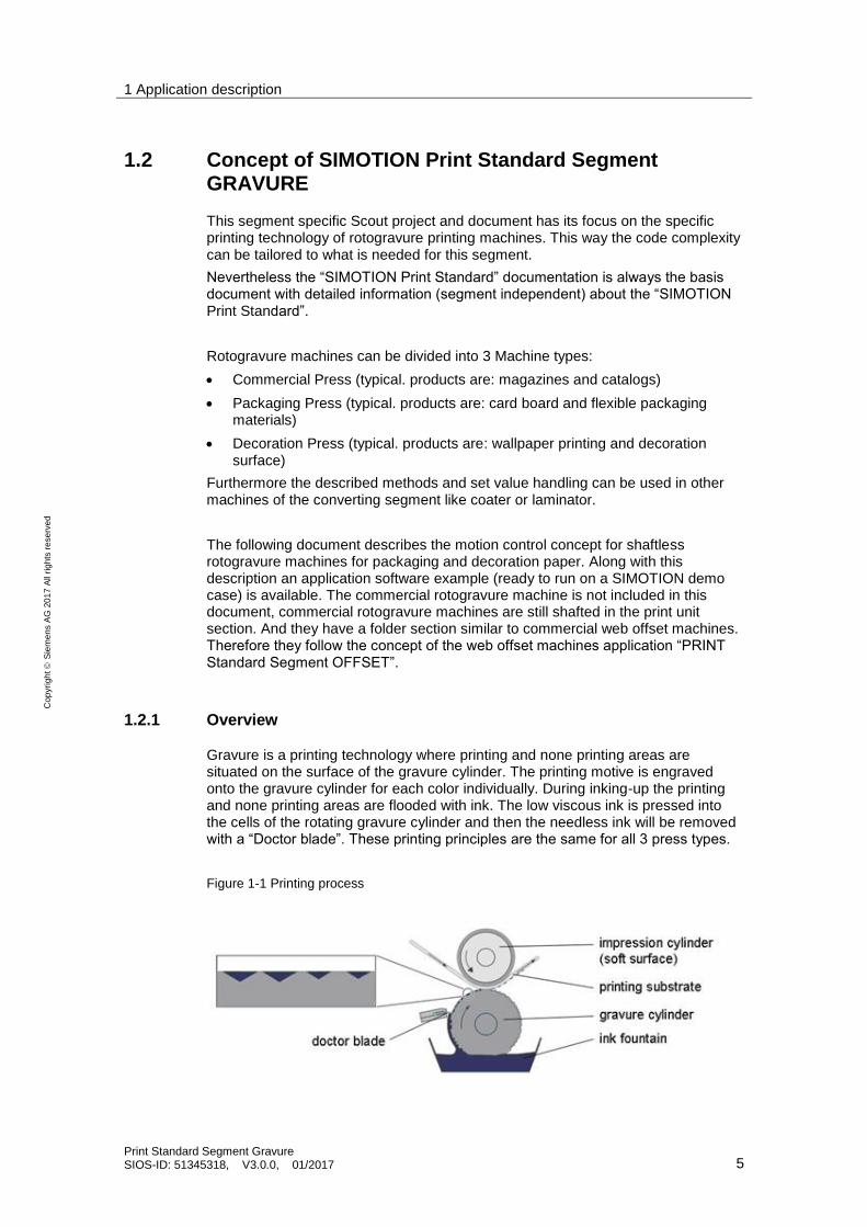
Gravure is a printing technology where printing and none printing areas are situated on the surface of the gravure cylinder. The printing motive is engraved onto the gravure cylinder for each color individually. During inking-up the printing and none printing areas are flooded with ink. The low viscous ink is pressed into the cells of the rotating gravure cylinder and then the needless ink will be removed with a “Doctor blade”. These printing principles are the same for all 3 press types.
Figure 1-1 Printing process
1 Application description
Print Standard Segment Gravure SIOS-ID: 51345318, V3.0.0, 01/2017 6
Cop
yri
gh
t
Sie
me
ns A
G 2
01
7 A
ll ri
gh
ts r
ese
rve
d
The steel cylinders with a thin copper surface (2mm) are engraved in special machines. After the engraving the cylinder surface gets a chromium layer (8 µm). The set of cylinders are tested in special presses, before the cylinders run in the production press. In decoration presses special cylinders, which are only one repeat wide, are tested for color and gravure proof. Commercial presses print the four base colors (cyan, magenta, blue and black) on each side of the web while packaging presses also print ornamental colors (like white, silver, gold, green) normally only on one side. Background or reverse side images are printed often with different format length, without register in tension control mode. Decoration presses often print with ornamental colors only (e.g. three different types of brown).
The low viscous ink is transferred with high pressure from the engraved cylinder directly to the printing substrate. The non driven impression cylinder has a soft surface and applies the pressure to the printing nip. The wet ink can’t be overprinted, therefore drying is obligatory after each printing element. The gravure cylinder is not only printing but mainly transporting the web. Therefore in electronic line shaft (ELS) machines the electronic register is directly affecting web transport and the web tension. With this all following registers are influenced immediately while the web is transported. The max. machine web speed typically is in the range of 250 m/min (film) to 700m/min (paper).
Machines for packing and decoration material are arranged in a roll-to-roll configuration. These machines are sometimes equipped with in line converting technologies like coating and laminating. For cigarette industry the presses often have stamping, embossing, coating and laminating units in line with the print units, and a sheeter or die cutting at the end.
A rotogravure machine has normally 5 to10 printing units (3 to 5 for decoration presses). And every production has a different set of printing cylinders. The gravure cylinder with variable formatlength is the important part of the machine,and needs to be exchanged for every product. Compared with other printing technologies, the imaging by engraving for printing cylinders is very costly and difficult. But because of the following advantages rotogravure is still an important printing segment:
+ Variable printing formats through different cylinder diameters
+ Long lifetime of cylinder (>1.000.000 copies), which can be stored for repeat orders
+ Many different kinds of printing colors applicable
+ Many different materials may be printed
+ High printing quality
+ Simple printing principle and machine design
On the other side, the application of rotogravure printing machine is restricted by some disadvantages:
− Solvent based colors (environment policy) for film as print substrate
− The engraving of the printing cylinder is very costly
− Every printing unit prints only one color on one side and needs a dryer in line
− For backside printing the web has to be turned after the dryer or pass the following print stations in reverse direction by a long complicate web path and different mounting of ink fountain and doctor blade.
1 Application description
Print Standard Segment Gravure SIOS-ID: 51345318, V3.0.0, 01/2017 7
Cop
yri
gh
t
Sie
me
ns A
G 2
01
7 A
ll ri
gh
ts r
ese
rve
d
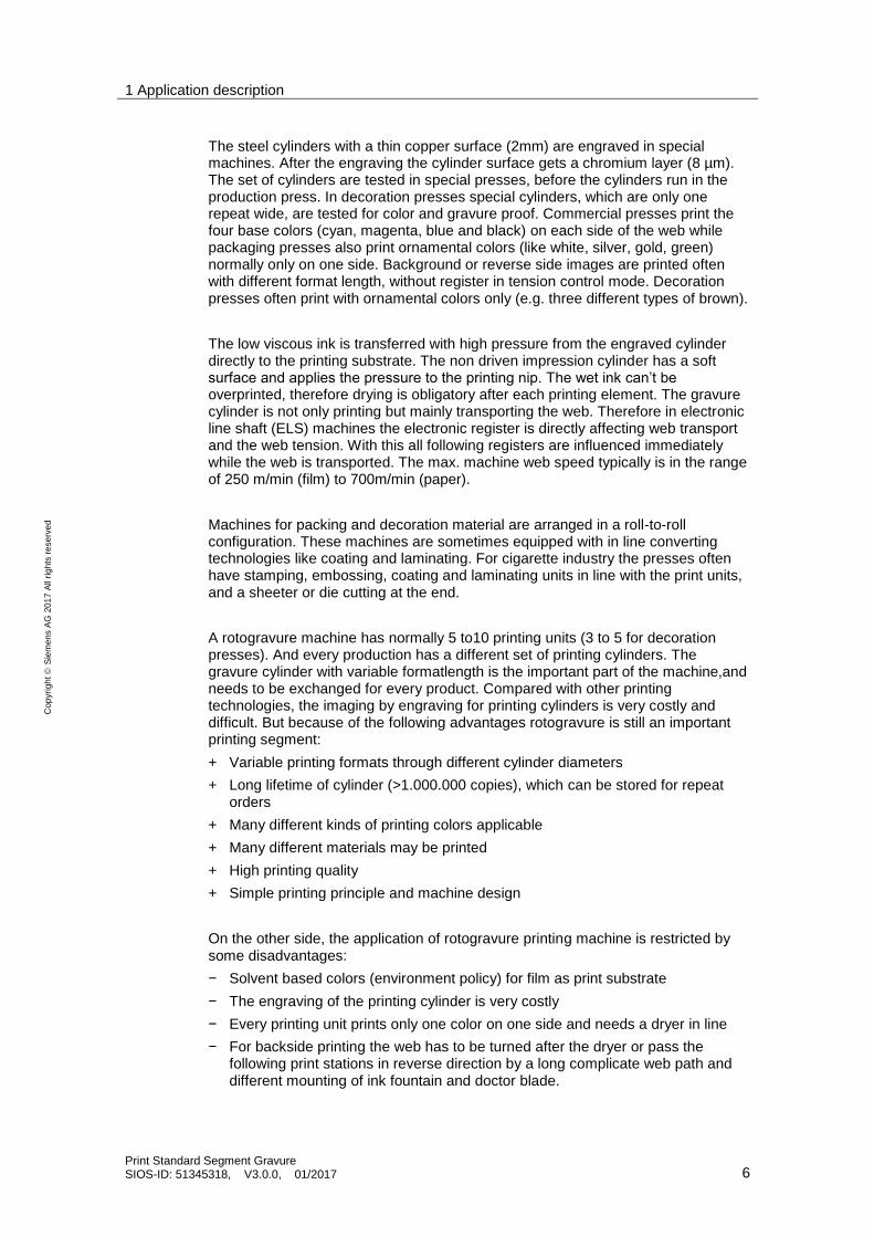
1.2.2 General machine specification of a rotogravure press
Figure 1-2 Basic example of a rotogravure printing machine
Typical machine specification of the rotogravure printing segment:
Machine length: 20m - 60m
Machine height: 4m - 10m
Number of units: 3…5 decoration machines
6…12 packing machines
Web speed: <250m/min shafted machines 250...450m/min shaftless machines (film) 400…700m/min shaftless decoration machines (paper)
Web width: 0,6..2m / 2..3 / >3m (packing / decoration / commercial)
Web tension: 40N … 500N machines for film
400N…1500N decoration machines for paper
400N…2200N machines for thick paper/carton board
(cigarette,liquid box)
Installed drive power: <20kW shafted machines 50…100kW shaftless machines (film) > 350kW shaftless decoration machines (paper)
1 Application description
Print Standard Segment Gravure SIOS-ID: 51345318, V3.0.0, 01/2017 8
Cop
yri
gh
t
Sie
me
ns A
G 2
01
7 A
ll ri
gh
ts r
ese
rve
d
1.2.3 Standard technological feature in rotogravure printing machine
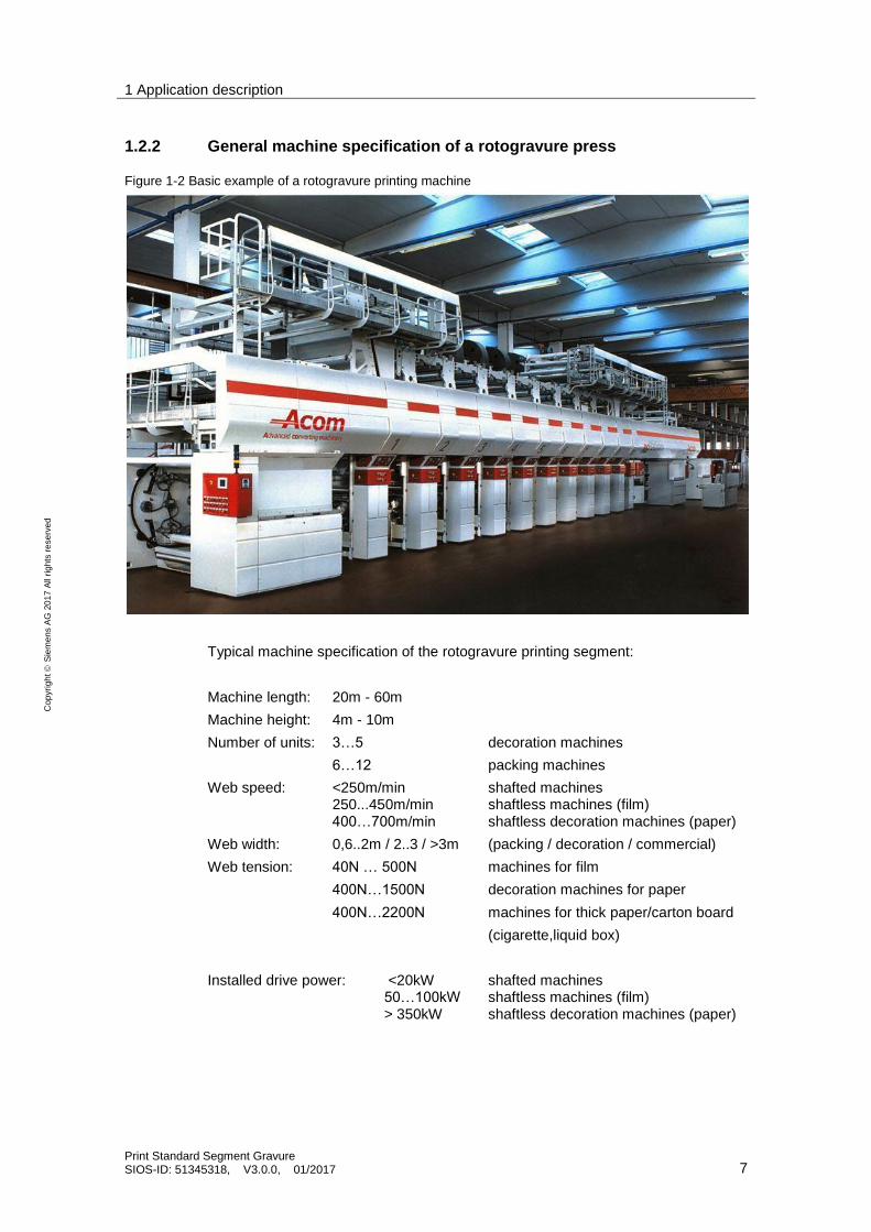
The following picture is the set value connection structure for a rotogravure machine with “SIMOTION Print Standard”.
Figure 1-3 Machine set value concept for Print Standard Gravure
The global master (GM) is responsible for the web speed controlling the whole machine. In “SIMOTION Print Standard” the GM is normalized to the web with a virtual format length of 360° = 1000 mm. All web transporting axes like infeed, pull rolls, outfeed and winder follow directly GM with gear ratio. The gear ratio is reflecting the circumference ratio of the individual rollers and the virtual format length of the GM. The “Additional Object” supplies the technological interface to the set values for segment specific functions of this axes.
All printing cylinders with machine format (RA-M) synchronize 1:1 to the local master (LM). The LM synchronizes to the global master with a gear ratio, which reflects the printing cylinder format of the actual product in the machine. Printing unit axes which don’t have the machine format (RA-L) also synchronize to the LM but with a gear ratio, which reflects theirs own cylinder format and the machine cylinder format. With this configuration all axes in the machine have the same web speed.
1 Application description
Print Standard Segment Gravure SIOS-ID: 51345318, V3.0.0, 01/2017 9
Cop
yri
gh
t
Sie
me
ns A
G 2
01
7 A
ll ri
gh
ts r
ese
rve
d
1.2.3.1 Virtual global master concept
The virtual master generates the position and speed set value as electronic line shaft (ELS) by math and software, which replaces the mechanical line shaft (MLS) for synchronization. In format variable rotogravure machines, the global master represents the web speed and is the direct reference for all web transporting axes. The format depending angular reference for the printing cylinder axes are generated by the local master using the electronic gear box function.
More virtual GM axes for the whole machine are possible. This depends on how many different productions have to be performed at the same time in the machine.
NOTICE The global virtual master as setpoint source for the machine could also be replaced by an external encoder. E.g. in case of retrofits or extensions of shafted machines with new machine modules. In this case the role of format master and web master might be switched.
Modular servo drive concept:
All servo drives are standardized using the same program code and interface to the PLC to offer the following standard servo functionality.
Following capability to master references ( “Gear Mode” to web or format master):
The drives can switch between possible masters depending on production and machine state. e.g. between “global master” of web 1 or web 2 or to a “format master”:
a. Angular synchronized (e.g. cylinders with machine format like gravure cylinders) with any adjustable register/phase offset e.g. 0 to 360 degree.
The phase / register value can be changed at any time absolute, relative or by Inch/jogging on top of the current machine speed. The total current phase is accumulated and stored in the drive.
b. Synchronized to match web speed with a dancer or loadcell controller
Independent drive operation (“Local Modes”): Each drive can perform the following modes in local operation independent of the rest of the machine at any time:
a. Local speed operation: Speed setpoint is given as setpoint value or via faster, slower, hold (Motorized Potentiometer MOP) functionality.
b. Local positioning operation: In this mode the drive can position the load cylinder at any given position. Positioning can be operated based on relative or absolute setpoints.
c. Local referencing mode: After motor/encoder change or during first time commissioning an alignment between encoder zero and mechanical load position can be performed using various “referencing” methods. Absolute and incremental encoder types can be referenced / homed via active and passive methods.
d. Modes of referencing on the fly for cylinder exchange are available.
1 Application description
Print Standard Segment Gravure SIOS-ID: 51345318, V3.0.0, 01/2017 10
Cop
yri
gh
t
Sie
me
ns A
G 2
01
7 A
ll ri
gh
ts r
ese
rve
d
The necessary dynamic rates (i.e. speed profile ramp up / ramp down times and rounding/jerk values) can be configured in the drive/motion system. Each technological drive mode has a different possible set of dynamics.
Standardized interface concept:
The Machine PLC program can control all drives/axes in the machine, the virtual (like virtual global machine masters) or the real (like all drives) in the exact same way using the same interface of control/actual data. With this concept the highest modularity and consistency is achieved.
GM – Virtual Global Master for machine operation and web reference:
GM is normalized to the web with the virtual format as web length of 1m=360°. GM is the reference for all web transporting axes like infeed, outfeed, winder or laminating units.
LM – Virtual Local Master for format reference:
The Local Master is used for the format reference. The format F is the nominal format of the gravure cylinder in production.
All gravure cylinders have to be coupled to the LM, independend of their format. If the actual format of a unit is not the machine format a gear factor must be set.
1.2.3.2 Axis concept
Two different types of real axes are used in the SIMOTION Print Standard segment rotogravure printing machine:
Web based:
Real Axis (RA):
These axes are “web transporting axes” like winder, infeed and outfeed. These axes have no relation to the machine format and therefore no register control. These axes are coupled directly to the global master (GM).
Angular based:
Real Axis Machine Format (RA M):
These axes are the gravure cylinders with machine format. The gear factor of these axes is 1:1. These axes are coupled to the local master LM.
Real Axis with Local Format (RA L)
Cylinders in local format run with tension control or manual ratio to web speed. The gear factors have to be set depending on the circumference of the cylinder. They are coupled to the local master LM, which gives the angular reference in machine format.
1 Application description
Print Standard Segment Gravure SIOS-ID: 51345318, V3.0.0, 01/2017 11
Cop
yri
gh
t
Sie
me
ns A
G 2
01
7 A
ll ri
gh
ts r
ese
rve
d
1.2.3.3 Technology concept
Addition Object
Each real axes has its own Addition Object. It is needed for technological functions like tension control, register control and register decoupling function.
Formula Object
Formula Objects are needed for winder axes. The formula Objects are unique for each winder axes and get their input from the FB Winder, which is executed in the IPO synchronous Task.
All axes especially the printing units with reference to the printed format of the format master are coupled 1:1 to the master in absolute synchronism. The offset between the real axis and the LM takes care of the individual register and web path between the units.
NOTICE Detailed description of the winder function can be found in a separate documentation Print Standard AddOn Reel Stand including an example project.
NOTICE Additional to format axes like the printing cylinders also sheeters, creaser and furthers format depending axes need to synchronize to the format master.
NOTICE Any printing unit can be equipped with a coating or laminating cylinder, which carries out a web based technology, and is closed loop tension controlled or controlled by a draw setpoint. The format difference between this cylinder and the master format needs to be taken care of by an electronic gear ratio.
2 Functional description
Print Standard Segment Gravure SIOS-ID: 51345318, V3.0.0, 01/2017 12
Cop
yri
gh
t
Sie
me
ns A
G 2
01
7 A
ll ri
gh
ts r
ese
rve
d
2 Functional description
2.1 Example of machine setpoint structure
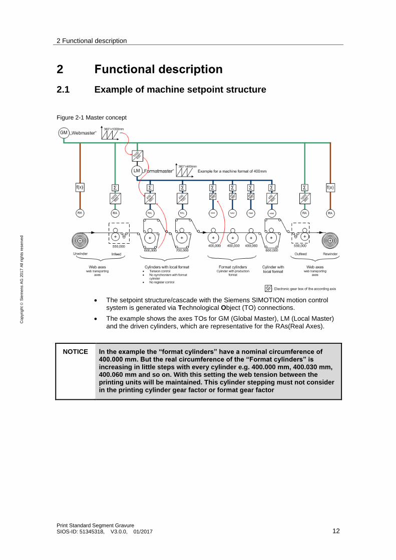
Figure 2-1 Master concept
The setpoint structure/cascade with the Siemens SIMOTION motion control system is generated via Technological Object (TO) connections.
The example shows the axes TOs for GM (Global Master), LM (Local Master) and the driven cylinders, which are representative for the RAs(Real Axes).
NOTICE In the example the “format cylinders” have a nominal circumference of 400.000 mm. But the real circumference of the “Format cylinders” is increasing in little steps with every cylinder e.g. 400.000 mm, 400.030 mm, 400.060 mm and so on. With this setting the web tension between the printing units will be maintained. This cylinder stepping must not consider in the printing cylinder gear factor or format gear factor
2 Functional description
Print Standard Segment Gravure SIOS-ID: 51345318, V3.0.0, 01/2017 13
Cop
yri
gh
t
Sie
me
ns A
G 2
01
7 A
ll ri
gh
ts r
ese
rve
d
2.1.1 Master concept for web transporting axes
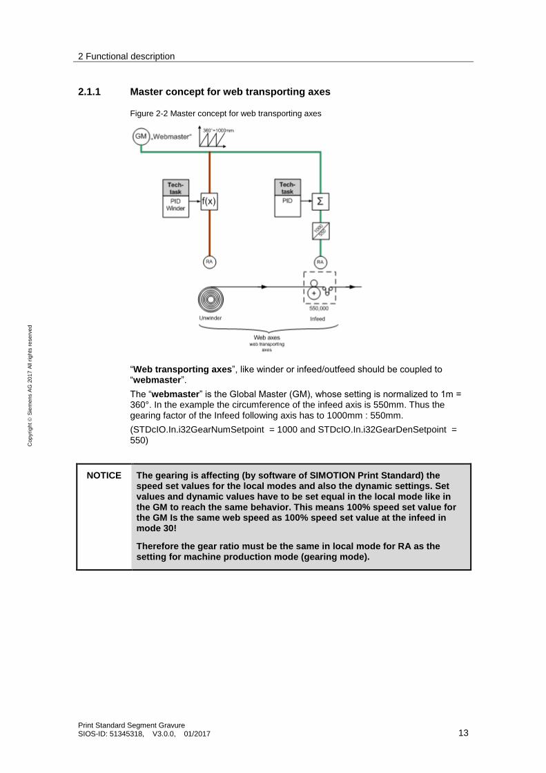
Figure 2-2 Master concept for web transporting axes
“Web transporting axes”, like winder or infeed/outfeed should be coupled to “webmaster”.
The “webmaster” is the Global Master (GM), whose setting is normalized to 1m = 360°. In the example the circumference of the infeed axis is 550mm. Thus the gearing factor of the Infeed following axis has to 1000mm : 550mm.
(STDcIO.In.i32GearNumSetpoint = 1000 and STDcIO.In.i32GearDenSetpoint = 550)
NOTICE The gearing is affecting (by software of SIMOTION Print Standard) the speed set values for the local modes and also the dynamic settings. Set values and dynamic values have to be set equal in the local mode like in the GM to reach the same behavior. This means 100% speed set value for the GM Is the same web speed as 100% speed set value at the infeed in mode 30!
Therefore the gear ratio must be the same in local mode for RA as the setting for machine production mode (gearing mode).
2 Functional description
Print Standard Segment Gravure SIOS-ID: 51345318, V3.0.0, 01/2017 14
Cop
yri
gh
t
Sie
me
ns A
G 2
01
7 A
ll ri
gh
ts r
ese
rve
d
2.1.2 Master concept for format axes / gravure axes
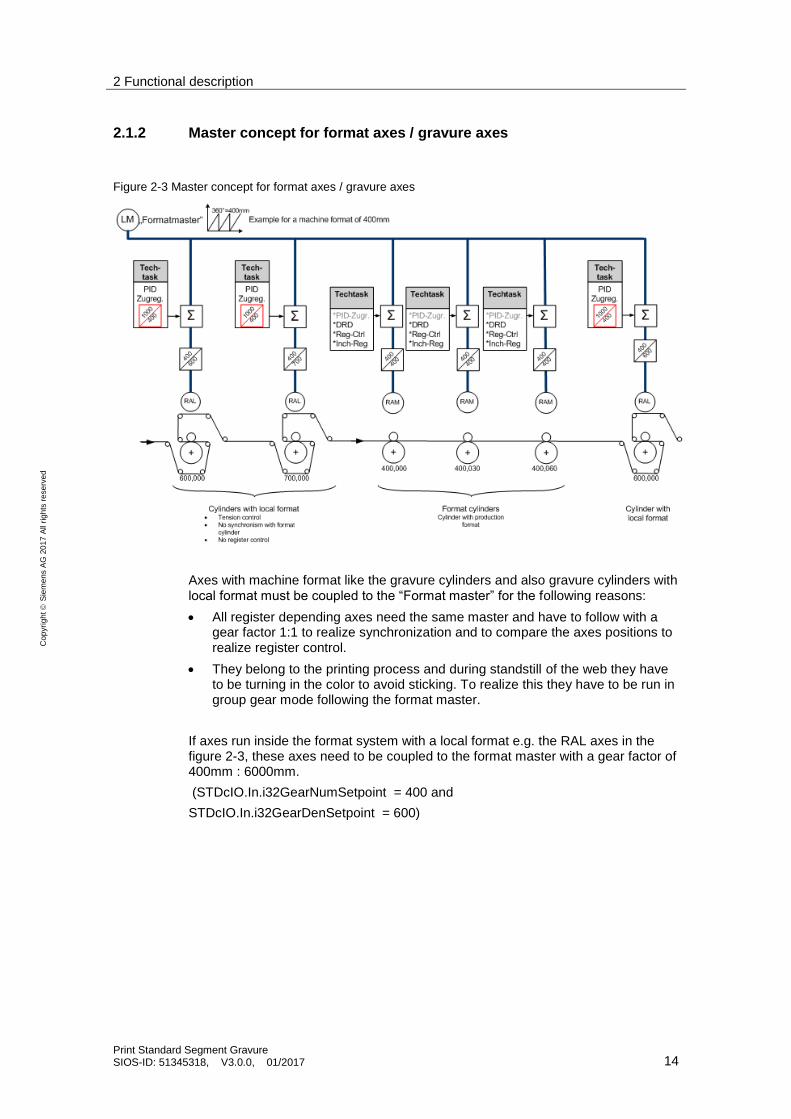
Figure 2-3 Master concept for format axes / gravure axes
Axes with machine format like the gravure cylinders and also gravure cylinders with local format must be coupled to the “Format master” for the following reasons:
All register depending axes need the same master and have to follow with a gear factor 1:1 to realize synchronization and to compare the axes positions to realize register control.
They belong to the printing process and during standstill of the web they have to be turning in the color to avoid sticking. To realize this they have to be run in group gear mode following the format master.
If axes run inside the format system with a local format e.g. the RAL axes in the figure 2-3, these axes need to be coupled to the format master with a gear factor of 400mm : 6000mm.
(STDcIO.In.i32GearNumSetpoint = 400 and
STDcIO.In.i32GearDenSetpoint = 600)
2 Functional description
Print Standard Segment Gravure SIOS-ID: 51345318, V3.0.0, 01/2017 15
Cop
yri
gh
t
Sie
me
ns A
G 2
01
7 A
ll ri
gh
ts r
ese
rve
d
NOTICE Generally in case of gearing the axis velocity will be adapted to the right surface velocity by its gear factor. If same axis will be used in local mode the without a gear factor the surface speed will be differ because of the normalization. If the surface velocity should be adapted to the right value in local mode also the gear factor has to be set also. The application will calculate the right value in reference to the gear factor.
E.g. in the figure 2-1:
If the GM is running with a velocity setpoint of 10% the FM and the following real axis surface velocity will be adapted by the gear factor of the FM (1000:400). In case of running these axis in local mode the surface speed of 10% will be only the same when the gear factor values will be send to the Print Standard interface.
2 Functional description
Print Standard Segment Gravure SIOS-ID: 51345318, V3.0.0, 01/2017 16
Cop
yri
gh
t
Sie
me
ns A
G 2
01
7 A
ll ri
gh
ts r
ese
rve
d
2.2 Example of gearing and normalization concept
This example is used to demonstrate the electronic gearing (format adaption) of the Print Standard application as well as the unit normalization based on the typical axes used in a gravure machine. As example the typical axes types of a shaftless machine will be described:
Virtual axes for web transport and format settings
Real axes for web transport (e.g. Infeed)
Real format depending axes (e.g. gravure cylinder PC_01, axis with local format (RA-L))
NOTICE Gear factor
Gear factor in this example documentation is the electronic gear factor to adopt the circumference speed of each cylinder to the web speed. It is not the physical gear factor of the motor gear box. This will be entered as a fix value in the mechanic screen of the SIMOTION technology object!
In the machine setpoint concept the following rules should will be followed:
All web transporting axes will be coupled to the web master GM
All register axes (with and without machine format) (PC0x and RA-M) must be coupled to the format master LM.
The TO system variable <axisName>.userdefaultdynamics.velocity needs to be the same value at every axes.
The speed setpoint of the Print Standard Interface is a percentage value of this system variable. The default value is 3600°/s. That means in the Print Standard basic application the GM with a reference circumference of 1m corresponds to a web speed of 600m/min at 100% speed setpoint.
In local modes on following axes the setpoint will be multiplied with the gear factor of the axis to calculate the correct surface speed.
R64SpeedSetpointInternal = StdcIO.In.r64SpeedSetpoint * StdcIO.In.i32GearNumSetpoint / StdcIO.In.i32GearDenSetpoint
The variable AxisConfigData.sCylinderFormat.r64ReferenceLength must be set to the real axis circumference (formatlength).
The dynamic rates of the axis will be adapted to the circumference at the motion commands
r64CylinderFormatlengthRatio =
AxisConfigData.sCylinderFormat.r64ReferenceLength /
STDcIO.In.r64ActualCylinderFormatlength
2 Functional description
Print Standard Segment Gravure SIOS-ID: 51345318, V3.0.0, 01/2017 17
Cop
yri
gh
t
Sie
me
ns A
G 2
01
7 A
ll ri
gh
ts r
ese
rve
d
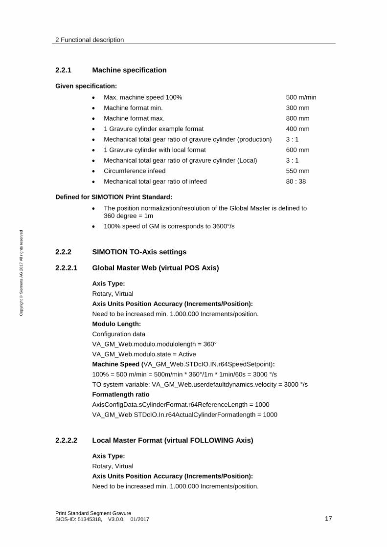
2.2.1 Machine specification
Given specification:
Max. machine speed 100% 500 m/min
Machine format min. 300 mm
Machine format max. 800 mm
1 Gravure cylinder example format 400 mm
Mechanical total gear ratio of gravure cylinder (production) 3 : 1
1 Gravure cylinder with local format 600 mm
Mechanical total gear ratio of gravure cylinder (Local) 3 : 1
Circumference infeed 550 mm
Mechanical total gear ratio of infeed 80 : 38
Defined for SIMOTION Print Standard:
The position normalization/resolution of the Global Master is defined to 360 degree = 1m
100% speed of GM is corresponds to 3600°/s
2.2.2 SIMOTION TO-Axis settings
2.2.2.1 Global Master Web (virtual POS Axis)
Axis Type:
Rotary, Virtual
Axis Units Position Accuracy (Increments/Position):
Need to be increased min. 1.000.000 Increments/position.
Modulo Length:
Configuration data
VA_GM_Web.modulo.modulolength = 360°
VA_GM_Web.modulo.state = Active
Machine Speed (VA_GM_Web.STDcIO.IN.r64SpeedSetpoint):
100% = 500 m/min = 500m/min * 360°/1m * 1min/60s = 3000 °/s
TO system variable: VA_GM_Web.userdefaultdynamics.velocity = 3000 °/s
Formatlength ratio
AxisConfigData.sCylinderFormat.r64ReferenceLength = 1000
VA_GM_Web STDcIO.In.r64ActualCylinderFormatlength = 1000
2.2.2.2 Local Master Format (virtual FOLLOWING Axis)
Axis Type:
Rotary, Virtual
Axis Units Position Accuracy (Increments/Position):
Need to be increased min. 1.000.000 Increments/position.
2 Functional description
Print Standard Segment Gravure SIOS-ID: 51345318, V3.0.0, 01/2017 18
Cop
yri
gh
t
Sie
me
ns A
G 2
01
7 A
ll ri
gh
ts r
ese
rve
d
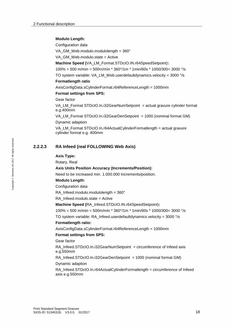
Modulo Length:
Configuration data
VA_GM_Web.modulo.modulolength = 360°
VA_GM_Web.modulo.state = Active
Machine Speed (VA_LM_Format.STDcIO.IN.r64SpeedSetpoint):
100% = 500 m/min = 500m/min * 360°/1m * 1min/60s * 1000/300= 3000 °/s
TO system variable: VA_LM_Web.userdefaultdynamics.velocity = 3000 °/s
Formatlength ratio
AxisConfigData.sCylinderFormat.r64ReferenceLength = 1000mm
Format settings from SPS:
Gear factor
VA_LM_Format STDcIO.In.i32GearNumSetpoint = actual gravure cylinder format e.g.400mm
VA_LM_Format STDcIO.In.i32GearDenSetpoint = 1000 (nominal format GM)
Dynamic adaption
VA_LM_Format STDcIO.In.r64ActualCylinderFormatlength = actual gravure cylinder format e.g. 400mm
2.2.2.3 RA Infeed (real FOLLOWING Web Axis)
Axis Type:
Rotary, Real
Axis Units Position Accuracy (Increments/Position):
Need to be increased min. 1.000.000 Increments/position.
Modulo Length:
Configuration data
RA_Infeed.modulo.modulolength = 360°
RA_Infeed.modulo.state = Active
Machine Speed (RA_Infeed.STDcIO.IN.r64SpeedSetpoint):
100% = 500 m/min = 500m/min * 360°/1m * 1min/60s * 1000/300= 3000 °/s
TO system variable: RA_Infeed.userdefaultdynamics.velocity = 3000 °/s
Formatlength ratio:
AxisConfigData.sCylinderFormat.r64ReferenceLength = 1000mm
Format settings from SPS:
Gear factor
RA_Infeed.STDcIO.In.i32GearNumSetpoint = circumference of Infeed axis e.g.550mm
RA_Infeed.STDcIO.In.i32GearDenSetpoint = 1000 (nominal format GM)
Dynamic adaption
RA_Infeed.STDcIO.In.r64ActualCylinderFormatlength = circumference of Infeed axis e.g.550mm
2 Functional description
Print Standard Segment Gravure SIOS-ID: 51345318, V3.0.0, 01/2017 19
Cop
yri
gh
t
Sie
me
ns A
G 2
01
7 A
ll ri
gh
ts r
ese
rve
d
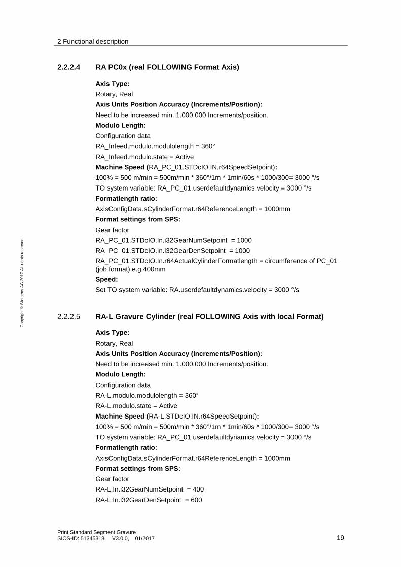
2.2.2.4 RA PC0x (real FOLLOWING Format Axis)
Axis Type:
Rotary, Real
Axis Units Position Accuracy (Increments/Position):
Need to be increased min. 1.000.000 Increments/position.
Modulo Length:
Configuration data
RA_Infeed.modulo.modulolength = 360°
RA_Infeed.modulo.state = Active
Machine Speed (RA_PC_01.STDcIO.IN.r64SpeedSetpoint):
100% = 500 m/min = 500m/min * 360°/1m * 1min/60s * 1000/300= 3000 °/s
TO system variable: RA_PC_01.userdefaultdynamics.velocity = 3000 °/s
Formatlength ratio:
AxisConfigData.sCylinderFormat.r64ReferenceLength = 1000mm
Format settings from SPS:
Gear factor
RA_PC_01.STDcIO.In.i32GearNumSetpoint = 1000
RA_PC_01.STDcIO.In.i32GearDenSetpoint = 1000
RA_PC_01.STDcIO.In.r64ActualCylinderFormatlength = circumference of PC_01 (job format) e.g.400mm
Speed:
Set TO system variable: RA.userdefaultdynamics.velocity = 3000 °/s
2.2.2.5 RA-L Gravure Cylinder (real FOLLOWING Axis with local Format)
Axis Type:
Rotary, Real
Axis Units Position Accuracy (Increments/Position):
Need to be increased min. 1.000.000 Increments/position.
Modulo Length:
Configuration data
RA-L.modulo.modulolength = 360°
RA-L.modulo.state = Active
Machine Speed (RA-L.STDcIO.IN.r64SpeedSetpoint):
100% = 500 m/min = 500m/min * 360°/1m * 1min/60s * 1000/300= 3000 °/s
TO system variable: RA_PC_01.userdefaultdynamics.velocity = 3000 °/s
Formatlength ratio:
AxisConfigData.sCylinderFormat.r64ReferenceLength = 1000mm
Format settings from SPS:
Gear factor
RA-L.In.i32GearNumSetpoint = 400
RA-L.In.i32GearDenSetpoint = 600
2 Functional description
Print Standard Segment Gravure SIOS-ID: 51345318, V3.0.0, 01/2017 20
Cop
yri
gh
t
Sie
me
ns A
G 2
01
7 A
ll ri
gh
ts r
ese
rve
d
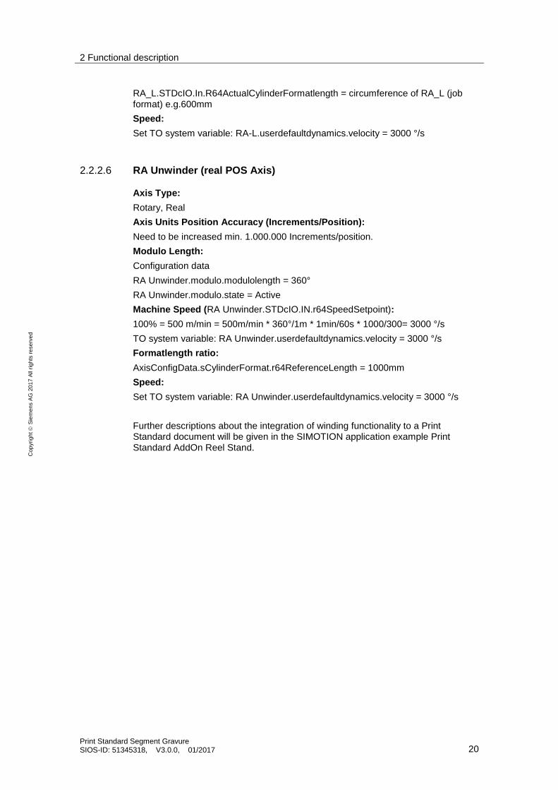
RA_L.STDcIO.In.R64ActualCylinderFormatlength = circumference of RA_L (job format) e.g.600mm
Speed:
Set TO system variable: RA-L.userdefaultdynamics.velocity = 3000 °/s
2.2.2.6 RA Unwinder (real POS Axis)
Axis Type:
Rotary, Real
Axis Units Position Accuracy (Increments/Position):
Need to be increased min. 1.000.000 Increments/position.
Modulo Length:
Configuration data
RA Unwinder.modulo.modulolength = 360°
RA Unwinder.modulo.state = Active
Machine Speed (RA Unwinder.STDcIO.IN.r64SpeedSetpoint):
100% = 500 m/min = 500m/min * 360°/1m * 1min/60s * 1000/300= 3000 °/s
TO system variable: RA Unwinder.userdefaultdynamics.velocity = 3000 °/s
Formatlength ratio:
AxisConfigData.sCylinderFormat.r64ReferenceLength = 1000mm
Speed:
Set TO system variable: RA Unwinder.userdefaultdynamics.velocity = 3000 °/s
Further descriptions about the integration of winding functionality to a Print Standard document will be given in the SIMOTION application example Print Standard AddOn Reel Stand.
2 Functional description
Print Standard Segment Gravure SIOS-ID: 51345318, V3.0.0, 01/2017 21
Cop
yri
gh
t
Sie
me
ns A
G 2
01
7 A
ll ri
gh
ts r
ese
rve
d
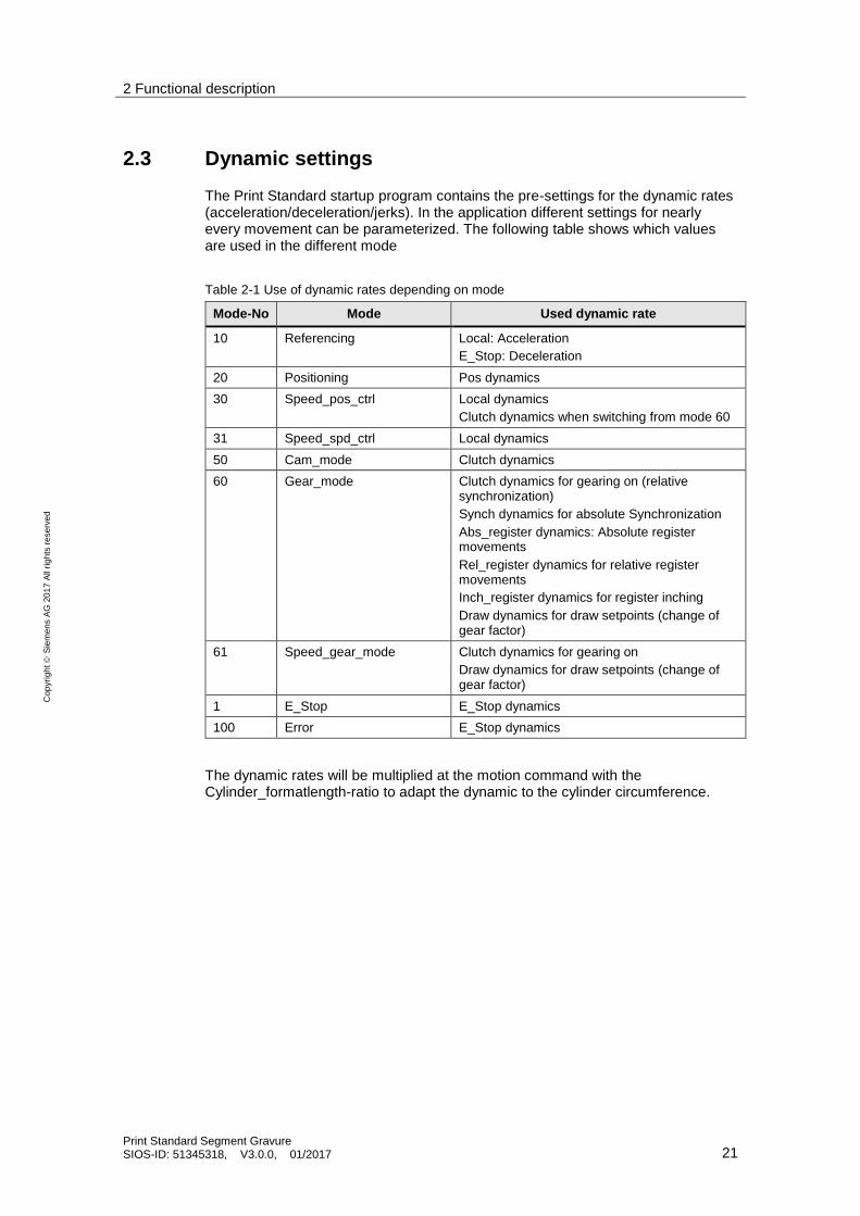
2.3 Dynamic settings
The Print Standard startup program contains the pre-settings for the dynamic rates (acceleration/deceleration/jerks). In the application different settings for nearly every movement can be parameterized. The following table shows which values are used in the different mode
Table 2-1 Use of dynamic rates depending on mode
Mode-No Mode Used dynamic rate
10 Referencing Local: Acceleration
E_Stop: Deceleration
20 Positioning Pos dynamics
30 Speed_pos_ctrl Local dynamics
Clutch dynamics when switching from mode 60
31 Speed_spd_ctrl Local dynamics
50 Cam_mode Clutch dynamics
60 Gear_mode Clutch dynamics for gearing on (relative synchronization)
Synch dynamics for absolute Synchronization
Abs_register dynamics: Absolute register movements
Rel_register dynamics for relative register movements
Inch_register dynamics for register inching
Draw dynamics for draw setpoints (change of gear factor)
61 Speed_gear_mode Clutch dynamics for gearing on
Draw dynamics for draw setpoints (change of gear factor)
1 E_Stop E_Stop dynamics
100 Error E_Stop dynamics
The dynamic rates will be multiplied at the motion command with the Cylinder_formatlength-ratio to adapt the dynamic to the cylinder circumference.
2 Functional description
Print Standard Segment Gravure SIOS-ID: 51345318, V3.0.0, 01/2017 22
Cop
yri
gh
t
Sie
me
ns A
G 2
01
7 A
ll ri
gh
ts r
ese
rve
d
2.3.1 Dynamic rates for GM – Webmaster
The Global Master in standard operation is typically running in mode 30. A standard stop will be realized in mode 30 also with r64SpeedSetpoint = 0. In case of fast stop the axis will be switched to mode 1 to stop with the fast dynamics of emergency stop.
GM Local Rates:
A desired ramp up/ramp down time to/from 100% machine speed of 60s (2s rounding) can be realized with the following dynamic values:
=> GM_AxisConfigData.sLocalDyn.r64Accel = 3000,0°/s / 60 s = 50,0°/s2 => GM_AxisConfigData.sLocalDyn.r64AcelJerk = 50,0°/s2 / 2 s = 25,0°/s3
=> GM_AxisConfigData.sLocalDyn.r64Decel = 3000,0°/s / 60 s = 50,0°/s2 => GM_AxisConfigData.sLocalDyn.r64DecelJerk = 50,0°/s2 / 2 s = 25,0°/s3
A desired ramp up/ramp down time to/from 100% machine speed of 40s (2s rounding) can be realized with the following dynamic values:
=> GM_AxisConfigData.sLocalDyn.r64Accel = 3000,0°/s / 40 s = 75,0°/s2 => GM_AxisConfigData.sLocalDyn.r64AcelJerk = 75°/s2 / 2 s = 37,5°/s3
=> GM_AxisConfigData.sLocalDyn.r64Decel = 3000,0°/s / 40 s = 75,0°/s2 => GM_AxisConfigData.sLocalDyn.r64DecelJerk = 75°/s2 / 2 s = 37,5°/s3
GM E-stop Rates:
A desired ramp up/ramp down time to/from 100% machine speed of 10s (0.1s rounding) can be realized with the following dynamic values:
=> GM_AxisConfigData.sLocalDyn.r64Decel = 3000°/s / 10 s = 300,0°/s2
=> GM_AxisConfigData.sLocalDyn.r64DecelJerk = 300,0°/s2 / 0,1 s = 3000,0°/s3
2.3.2 Dynamic rates for LM – Format master
The LM is typically running in relative gearing to the GM. The gear factor is 1000mm reference format to the respective job format. Register functionalities are not used at this axis. During standstill of the machine the LM is running in local mode to move the cylinders in the ink.
The following dynamics will be used generally:
LM Local Rates:
A desired ramp up/ramp down time to/from 100% machine speed of 60s (2s rounding) can be realized with the following dynamic values:
=> LM_AxisConfigData.sLocalDyn.r64Accel = 3000,0°/s / 60 s = 50,0°/s2
=> LM_AxisConfigData.sLocalDyn.r64AcelJerk = 50,0°/s2 / 2 s = 25,0°/s3
=> LM_AxisConfigData.sLocalDyn.r64Decel = 3000,0°/s / 60 s = 50,0°/s2
=> LM_AxisConfigData.sLocalDyn.r64DecelJerk = 50,0°/s2 / 2 s = 25,0°/s3
A desired ramp up/ramp down time to/from 100% machine speed of 40s (2s rounding) can be realized with the following dynamic values:
=> LM_AxisConfigData.sLocalDyn.r64Accel = 3000,0°/s / 40 s = 75,0°/s2
2 Functional description
Print Standard Segment Gravure SIOS-ID: 51345318, V3.0.0, 01/2017 23
Cop
yri
gh
t
Sie
me
ns A
G 2
01
7 A
ll ri
gh
ts r
ese
rve
d
=> LM_AxisConfigData.sLocalDyn.r64AcelJerk = 75°/s2 / 2 s = 37,5°/s3
=> LM_AxisConfigData.sLocalDyn.r64Decel = 3000,0°/s / 40 s = 75,0°/s2
=> LM_AxisConfigData.sLocalDyn.r64DecelJerk = 75°/s2 / 2 s = 37,5°/s3
LM E-stop Rates:
A desired ramp up/ramp down time to/from 100% machine speed of 10s (0.1s rounding) can be realized with the following dynamic values:
=> LM_AxisConfigData.sLocalDyn.r64Decel = 3000°/s / 10 s = 300,0°/s2
=> LM_AxisConfigData.sLocalDyn.r64DecelJerk = 300,0°/s2 / 0,1 s = 3000,0°/s3
LM Clutch Rates:
In most cases the LM will be clutched to the master during standstill and no movements happens. If the GM is in operation the LM is synchronizing with the following default rates:
=> LM_AxisConfigData.sClutchDyn.r64Acel = 450,0°/s2
=> LM_AxisConfigData.sClutchDyn.r64Decel = 450,0°/s2
Speed and dynamic limitations:
Because of the gearing depending dynamic adaption the maximum dynamics of the TO axis has to be observed. If the GM will run with a maximum speed of 3000°/s and the LM gear factor is 1000/400 the printing cylinders will run much faster with 7500°/s. It needs to be sure that the maximum values of the TO in SIMOTION are calculated to this values as well as the limitations of the SINAMICS drive.
2.3.3 Dynamic rates for Real Axes
Real axes are typically using all available modes. Because of the three different kinds of axes following, positioning and drive axes, also three different structures for the pre-settings are available. Depending on the axis technology the respective structure need to be connected to the Print Standard Background function block.
RAF_AxisConfigData (RAF real axis following)
RAP_AxisConfigData (RAF real axis positioning)
RAD_AxisConfigData (RAF real axis drive)
All useable values for the axis types are available.
Generally the settings could be the same like the virtual axes but The LM is typically running in relative gearing to the GM. The gear factor is 1000mm reference format to the respective job format. Register functionalities are not used at this axis. During standstill of the machine the LM is running in local mode to move the cylinders in the ink.
The following dynamics will be used generally:
2 Functional description
Print Standard Segment Gravure SIOS-ID: 51345318, V3.0.0, 01/2017 24
Cop
yri
gh
t
Sie
me
ns A
G 2
01
7 A
ll ri
gh
ts r
ese
rve
d
RA Local Rates:
A desired ramp up/ramp down time to/from 100% machine speed of 60s (2s rounding) can be realized with the following dynamic values:
=> RAx_AxisConfigData.sLocalDyn.r64Accel = 3000,0°/s / 60 s = 50,0°/s2
=> RAx_AxisConfigData.sLocalDyn.r64AcelJerk = 50,0°/s2 / 2 s = 25,0°/s3
=> RAx_AxisConfigData.sLocalDyn.r64Decel = 3000,0°/s / 60 s = 50,0°/s2
=> RAx_AxisConfigData.sLocalDyn.r64DecelJerk = 50,0°/s2 / 2 s = 25,0°/s3
A desired ramp up/ramp down time to/from 100% machine speed of 40s (2s rounding) can be realized with the following dynamic values:
=> RAx_AxisConfigData.sLocalDyn.r64Accel = 3000,0°/s / 40 s = 75,0°/s2
=> RAx_AxisConfigData.sLocalDyn.r64AcelJerk = 75°/s2 / 2 s = 37,5°/s3
=> RAx_AxisConfigData.sLocalDyn.r64Decel = 3000,0°/s / 40 s = 75,0°/s2
=> RAx_AxisConfigData.sLocalDyn.r64DecelJerk = 75°/s2 / 2 s = 37,5°/s3
RA Positioning Rates:
A desired 1s from 0 to positioning speed (e.g. 550mm/s) with 0.2s rounding
=> RAx_AxisConfigData.sLocalDyn.r64Decel = 550 mm/s / 1 s * 360°/1000 mm = 198,0°/s2
=> RAx_AxisConfigData.sLocalDyn.r64DecelJerk = 198,0°/s2 / 0,2 s = 990,0°/s3
RA E-stop Rates:
A desired ramp up/ramp down time to/from 100% machine speed of 10s (0.1s rounding) can be realized with the following dynamic values:
=> RAx_AxisConfigData.sLocalDyn.r64Decel = 3000°/s / 10 s = 300,0°/s2
=> RAx_AxisConfigData.sLocalDyn.r64DecelJerk = 300,0°/s2 / 0,1 s = 3000,0°/s3
RA Clutch Rates:
In most cases the RAF will be clutched to the master during standstill and no movements happen. If the GM is in operation the RAF is synchronizing with the following default rates:
=> RAx_AxisConfigData.sClutchDyn.r64Acel = 200,0°/s2
=> RAx_AxisConfigData.sClutchDyn.r64Decel = 200,0°/s2
RA Register Speeds and Rates (Abs/ Rel/ Inch):
Angle offset to the local LM format master can be realized in 3 different ways. Absolute shift, relative shift and register inching. These dynamics can be entered for each type separately, the reaction is basically the same.
The speed is a percentage value of the axis reference speed (0.5% of max. press speed = 15 °/s).
=> RAF_AxisConfigData.sAbsRegisterDyn.r64Velo = 0,5 %
=> RAF_AxisConfigData.sRelRegisterDyn.r64Velo = 0,5 %
=> RAF_AxisConfigData.sInchRegisterDyn.r64Velo = 0,5 %
2 Functional description
Print Standard Segment Gravure SIOS-ID: 51345318, V3.0.0, 01/2017 25
Cop
yri
gh
t
Sie
me
ns A
G 2
01
7 A
ll ri
gh
ts r
ese
rve
d
The register speed will be reached with the following dynamics
e.g. desired 1s from 0 to registration speed of 0.5% (=15°/s) with 0.1 s rounding:
=> RA_AxisConfigData.sAbsRegisterDyn.r64Acel = 15°/s / 1 s = 15,0°/s2
=> RA_AxisConfigData.sRelRegisterDyn.r64Acel = 15°/s / 1 s = 15,0°/s2
=> RA_AxisConfigData.sInchRegisterDyn.r64Acel = 15°/s / 1 s = 15,0°/s2
=> RA_AxisConfigData.sAbsRegisterDyn.r64AcelJerk = 15°/s2 / 0,1 s = 150,0°/s3
=> RA_AxisConfigData.sRelRegisterDyn.r64AcelJerk = 15°/s2 / 0,1 s = 150,0°/s3
=> RA_AxisConfigData.sInchRegisterDyn.r64AcelJerk = 15°/s2 / 0,1 s = 150,0°/s3
The same dynamic value will be used for the deceleration values.
RA Synchronization Speed and Rates:
The synchronization speed and dynamic values will be used for the angle synchronization between master and slave axis. The axis can be synchronize to the master zero position or with an angle offset.
The speed is a percentage value of the axis reference speed (0.5% of max. press speed = 15 °/s).
=> RAF_AxisConfigData.sSynchDyn.r64Velo = 0,5 %
The register speed will be reached with the following dynamics
e.g. desired 1s from 0 to registration speed of 0.5% (=15°/s) with 0.1 s rounding:
=> RA_AxisConfigData.sSynchDyn.r64Acel = 15°/s / 1 s = 15,0°/s2
=> RA_AxisConfigData.sSynchDyn.r64AcelJerk = 15°/s2 / 0,1 s = 150,0°/s3
=> RA_AxisConfigData.sSynchDyn.r64Decel = 15°/s / 1 s = 15,0°/s2
=> RA_AxisConfigData.sSynchDyn.r64DecelJerk = 15°/s2 / 0,1 s = 150,0°/s3
Also important for synchronization is the synchronizing direction. Especially in gravure printing machines only a forward synchronization is possible. The synchronizing direction can be set with:
=> RA_AxisConfigData.eSynchMode = FORWARD
CAUTION Generally it is possible to realize synchronization or register movements in the backward direction during operation as long as the resulting speed of basic movement (machine setpoint) and additional movement (register/sync setpoint) stays positive.
2 Functional description
Print Standard Segment Gravure SIOS-ID: 51345318, V3.0.0, 01/2017 26
Cop
yri
gh
t
Sie
me
ns A
G 2
01
7 A
ll ri
gh
ts r
ese
rve
d
RA Draw Rates:
For following axes with web routing functionality it might be useful to have the possibility to change the gear factor during operation to create more or less tension. This can be realized by using the draw functionality
The following rates will be used for changing the gear factor
=> RA_AxisConfigData.sDrawDyn.r64Acel = 3000°/s / 200 s = 15,00°/s2
=> RA_AxisConfigData.sDrawDyn.r64AcelJerk = 15°/s2 / 0,1 s = 150,00°/s3
=> RA_AxisConfigData.sDrawDyn.r64Decel = 3000°/s / 200 s = 15,00°/s2
=> RA_AxisConfigData.sDrawDyn.r64DecelJerk = 15°/s2 / 0,1 s = 150,00°/s3
Speed and dynamic limitations:
Because of the gearing depending dynamic adaption the maximum dynamics of the TO axis has to be observed. If the GM will run with a maximum speed of 3000°/s and the LM gear factor is 1000/400 the printing cylinders will run much faster with 7500°/s. It needs to be sure that the maximum values of the TO in SIMOTION are calculated to this values as well as the limitations of the SINAMICS drive.
2 Functional description
Print Standard Segment Gravure SIOS-ID: 51345318, V3.0.0, 01/2017 27
Cop
yri
gh
t
Sie
me
ns A
G 2
01
7 A
ll ri
gh
ts r
ese
rve
d
2.4 Technological Functions
For rotogravure printing machines typical technological functions are tension control, torque limitations and inhibit reverse movements, register movements and decoupling of register movements. Very often print units can also work with different technologies. One time a print unit works as a print unit and sometimes it works as a tension unit.
To realize these different technological extensions and have the possibility to influence the axis setpoint cascade, the Print Standard is using additional SIMOTION technology objects (Addition Object/ Formula Object).
A general description how to use and integrate these objects can be found in the Print Standard master documentation.
All available extensions will be explained shortly in the next chapters. For detailed information further documents are available.
2.4.1 Dynamic Register Decoupling DRD
A special behavior of a rotogravure printing machines is, that the impression cylinder (pressure) and the printing cylinder have a high nip pressure. This is necessary to transfer the color from the gravure cylinder to the material.
In consequence of the high pressure a register movement on the cylinder is not only correcting the cylinder position, it is also shifting the web. The web after the following printing cylinder and this printing cylinder gets stretched and the result of the register correction will be seen first after all stretched material between these two cylinders has moved out. After this dead time the result can be seen in the register evaluation.
Also the correction is producing an additional register deviation at the following print units. This can be resulting in a lot of waste. To avoid this, the functionality of DRD (direct register decoupling) can be used. If a printing unit will be corrected the register correction will be transferred automatically to all following printing units which make the register control system much faster and more stable. It leads at the end to less waste and higher print quality.
For more information about the Dynamic Register Decoupling read the documentation “Print Standard AddOn DRD”.
2.4.2 Tension Control
Tension control will be used in nearly every web transporting machine. The Print Standard master project contains an example for tension control. It is using the standard function block “FBTechnologyController” from the Converting library “LConLib”.
For the further description please use the document “manual converting library” and “SIMOTION Print Standard”
In the SCOUT project a parameter presetting for winder FB and tension FB is applied in the program “T_Startup”.
2 Functional description
Print Standard Segment Gravure SIOS-ID: 51345318, V3.0.0, 01/2017 28
Cop
yri
gh
t
Sie
me
ns A
G 2
01
7 A
ll ri
gh
ts r
ese
rve
d
2.4.3 Winding
For the implementation of winding to Print Standard projects a separate application
with documentation and project based on a working example is available
SIMOTION Print Standard Add On Reel Stand.
2.4.4 Register Control
Next to the basic register functionalities of the Print Standard application, absolute, relative register and register inching an integrated register control system with different evaluation hardware for point and block marks is available for SIMOTION.
Print Standard Add On TRC1000
Print Standard Add On TRC3000
Print Standard Add On TRC7000
These solutions from entry level to top level contain a working application example with visualization.
2.4.5 Mechanical length register with register rolls
Especially for rotogravure machines with mechanical line shaft a solution for register control with register rolls is necessary.
2 Functional description
Print Standard Segment Gravure SIOS-ID: 51345318, V3.0.0, 01/2017 29
Cop
yri
gh
t
Sie
me
ns A
G 2
01
7 A
ll ri
gh
ts r
ese
rve
d
2.5 Integration of technology functions in Print Standard
Technology functions like Winding, Tension Control, Register Control or DRD can be executed in different parts of the program and finally included to the Print Standard setpoint channel.
Dependent on the amount of the technology function the additional program parts can be integrated into the already existing Print Standard program unit (e.g. pRA_PC_01) or using a separate program unit.
2.5.1 Integration in Print Standard axis program unit
In case the technology function is only small amount it make sense to integrate the necessary program part into the Print Standard axis unit. In this way all functions related to this axis is combined in one program unit.
The Segment GRAVURE example project shows this.
In addition to the Print Standard IPO function block FBLPrint_StdAxisIpo a technology function like winding or DRD is called in the same program unit. The Print Standard FBTech is used to integrate the additional setpoint to the Print Standard setpoint cascade.
The integration of an extern register control system can be realized in the same way.
2.5.2 Integration as separate program unit
In case the technology function has bigger amount of program code it is useful to outsource this program part into a separate program unit.
The advantage of doing so: Print Standard and technology function are encapsulated. They can be replaced/updated independent from each other very easily. The clarity of each functions remain.
Disadvantage might be the separation of functions actually belonging to one axis.
The Siemens integrated register control solution (Print Standard Add-On TRC3000/7000) shows this concept.
3 Abbreviations
Print Standard Segment Gravure SIOS-ID: 51345318, V3.0.0, 01/2017 30
Cop
yri
gh
t
Sie
me
ns A
G 2
01
7 A
ll ri
gh
ts r
ese
rve
d
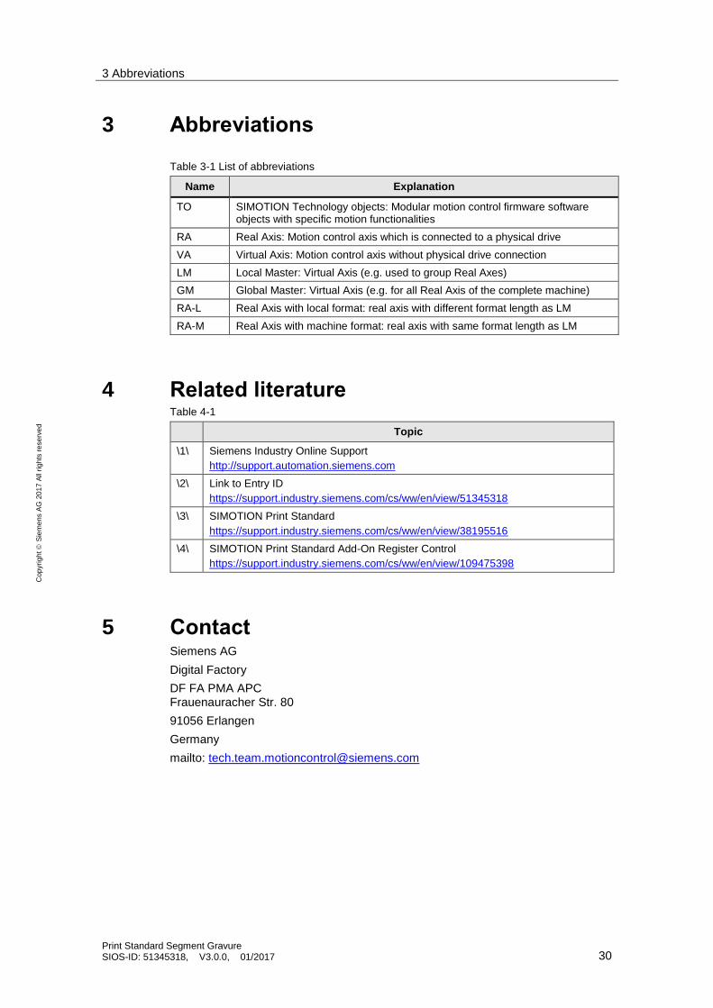
3 Abbreviations
Table 3-1 List of abbreviations
Name Explanation
TO SIMOTION Technology objects: Modular motion control firmware software objects with specific motion functionalities
RA Real Axis: Motion control axis which is connected to a physical drive
VA Virtual Axis: Motion control axis without physical drive connection
LM Local Master: Virtual Axis (e.g. used to group Real Axes)
GM Global Master: Virtual Axis (e.g. for all Real Axis of the complete machine)
RA-L Real Axis with local format: real axis with different format length as LM
RA-M Real Axis with machine format: real axis with same format length as LM
4 Related literature Table 4-1
Topic
\1\ Siemens Industry Online Support
http://support.automation.siemens.com
\2\ Link to Entry ID
https://support.industry.siemens.com/cs/ww/en/view/51345318
\3\ SIMOTION Print Standard
https://support.industry.siemens.com/cs/ww/en/view/38195516
\4\ SIMOTION Print Standard Add-On Register Control
https://support.industry.siemens.com/cs/ww/en/view/109475398
5 Contact Siemens AG
Digital Factory
DF FA PMA APC Frauenauracher Str. 80
91056 Erlangen
Germany
mailto: [email protected]

6 History
Print Standard Segment Gravure SIOS-ID: 51345318, V3.0.0, 01/2017 31
Cop
yri
gh
t
Sie
me
ns A
G 2
01
7 A
ll ri
gh
ts r
ese
rve
d
6 History Table 6-1
Version Date Modifications
V1.0 06/2011 Created
V2.0 11/2013 SIPS OS
DRD description
V2.2.1.0 07/2015 revised
V3.0.0 01/2017 Updated to new Print Standard library V3.x.x