Embed Size (px)
Citation preview
ApplianceQuick Start Guidev8.4.3Rev. 1.0.1
Copyright © Loadbalancer.org
Table of Contents
1. About this Guide.........................................................................................................................................3
2. Appliance Configuration Overview.....................................................................................................3
3. Appliance Security.....................................................................................................................................3Security Mode.......................................................................................................................................................................... 3
Default Passwords.................................................................................................................................................................. 4
Security Lockdown Script.................................................................................................................................................... 4
4. Deployment Concept..............................................................................................................................4
5. One-Arm and Two-Arm Topologies...................................................................................................5
6. Load Balancing Methods........................................................................................................................6
7. Appliance Deployment............................................................................................................................7Virtual Appliance..................................................................................................................................................................... 7
Hardware Appliance............................................................................................................................................................... 7
Cloud Appliance...................................................................................................................................................................... 7
AWS......................................................................................................................................................................................... 7
Azure....................................................................................................................................................................................... 7
8. Configuring Initial Network Settings..................................................................................................7Using the Network Setup Wizard.................................................................................................................................. 8
Using the WebUI................................................................................................................................................................ 11
9. Accessing the Web User Interface (WebUI)....................................................................................11
10. Ports Used by the Appliance.............................................................................................................13
11. Licensing...................................................................................................................................................13
12. Software Updates..................................................................................................................................13
13. Configuring & Testing a Simple Load Balanced Test Environment.....................................14STEP 1 – Deploy the Appliance........................................................................................................................................ 14
STEP 2 – Run the Network Setup Wizard..................................................................................................................... 14
STEP 3 – Run the WebUI Setup Wizard......................................................................................................................... 14
STEP 4 – Viewing & Modifying the Configuration..................................................................................................... 16
STEP 5 – Checking the Status using System Overview............................................................................................17
STEP 6 – Verification & Testing........................................................................................................................................ 17
14. Configuring HA – Adding a Slave Appliance...............................................................................18
15. More Information..................................................................................................................................19
16. Loadbalancer.org Technical Support.............................................................................................19
17. Company Contact Information.......................................................................................................20
Appliance Quick Start Guide v8.4.3
About this Guide
1. About this GuideThis quick start guide provides enough information to deploy the appliance, configure a simple load balanced test environment and test and verify its functionality.
Note:
Please also refer to the Administration Manual for much more detailed information on setting upthe appliance and configuring a load balanced solution. For information on configuring the appliance for specific applications, please refer to our extensive library of Deployment Guides.
2. Appliance Configuration OverviewInitial network configuration can be carried out at the console by using the Network Setup Wizard or by connecting to the default IP address & port using a browser (https://192.168.2.21:9443) and making changes using the WebUI. For details of both options please refer to page 7.
Once the network has been configured and the appliance has an IP address, load balanced services can beconfigured using the WebUI, either using the Setup Wizard (for Layer 7 services) or by manually defining the Virtual Services (VIPs) and associated Real Servers (RIPs).
By default, the WebUI is accessible on HTTPS port 9443. HTTP access on port 9080 can also be enabled if required as explained in the section “Appliance Security” below.
We always recommend that where possible two appliances are deployed as a clustered pair for high availability and resilience, this avoids introducing a single point of failure to your network. We recommend that the master is fully configured first, then the slave should be added. For more information on configuring an HA pair please refer to page 18. Once a pair is configured, load balanced services must be configured & modified on the master appliance. The slave appliance will then be kept in sync automatically.
3. Appliance Security
SECURITY MODETo control how the appliance is accessed and which features are enabled, 3 security modes are provided:
• Secure – this is the default mode. In this mode:
◦ the WebUI is accessible on HTTPS port 9443. If you attempt to access the WebUI on HTTP port 9080 you will be redirected to HTTPS port 9443
◦ access to the “Execute Shell Command” menu option is disabled
◦ the ability to edit the firewall script & the lockdown wizard is disabled
◦ 'root' user console & SSH password access are disabled
• Custom – In this mode, the security options can be configured to suit your requirements
• Secure – Permanent – this mode is the same as Secure, but the change is irreversible
IMPORTANT:
Only set the security mode to Secure – Permanent if you are 100% sure this is what you want!
Appliance Quick Start Guide v8.4.3
Page 3
Appliance Security
To configure the Security Mode:
1. Using the WebUI, navigate to: Local Configuration > Security
2. Select the required Appliance Security Mode
3. If Custom is selected, configure the other options to suit your requirements
4. Click Update
Note:
For full details of all options, please refer to the Administration Manual (page 80).
DEFAULT PASSWORDSWe strongly recommend that default passwords are changed as soon as the appliance is deployed.
1 – the 'root' Linux account:
As explained on page 3, 'root' user console & SSH password access are disabled by default. If enabled, the 'root' password should be changed at the console, or via an SSH session using the following command:
passwd
2 – the 'loadbalancer' WebUI account:
This can be changed using the WebUI menu option: Maintenance > Passwords
SECURITY LOCKDOWN SCRIPTThe appliance also includes a security lockdown command (lbsecure) that enables passwords to be set, network access to be locked down and SSH key regeneration in one simple step. This command can be run on a single appliance or an HA pair. For more details please refer to the Administration Manual (page 78).
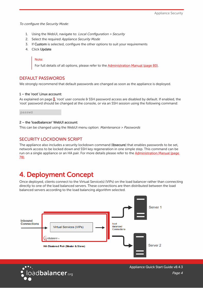
4. Deployment ConceptOnce deployed, clients connect to the Virtual Service(s) (VIPs) on the load balancer rather than connecting directly to one of the load balanced servers. These connections are then distributed between the load balanced servers according to the load balancing algorithm selected.
Appliance Quick Start Guide v8.4.3
Page 4
Deployment Concept
Note:
We recommend that 2 appliances are deployed as an active/passive HA pair as shown above. The slave appliance automatically takes over if the master unit fails. Please refer to page 18 for more information on setting up an HA pair of Loadbalancer.org appliances.
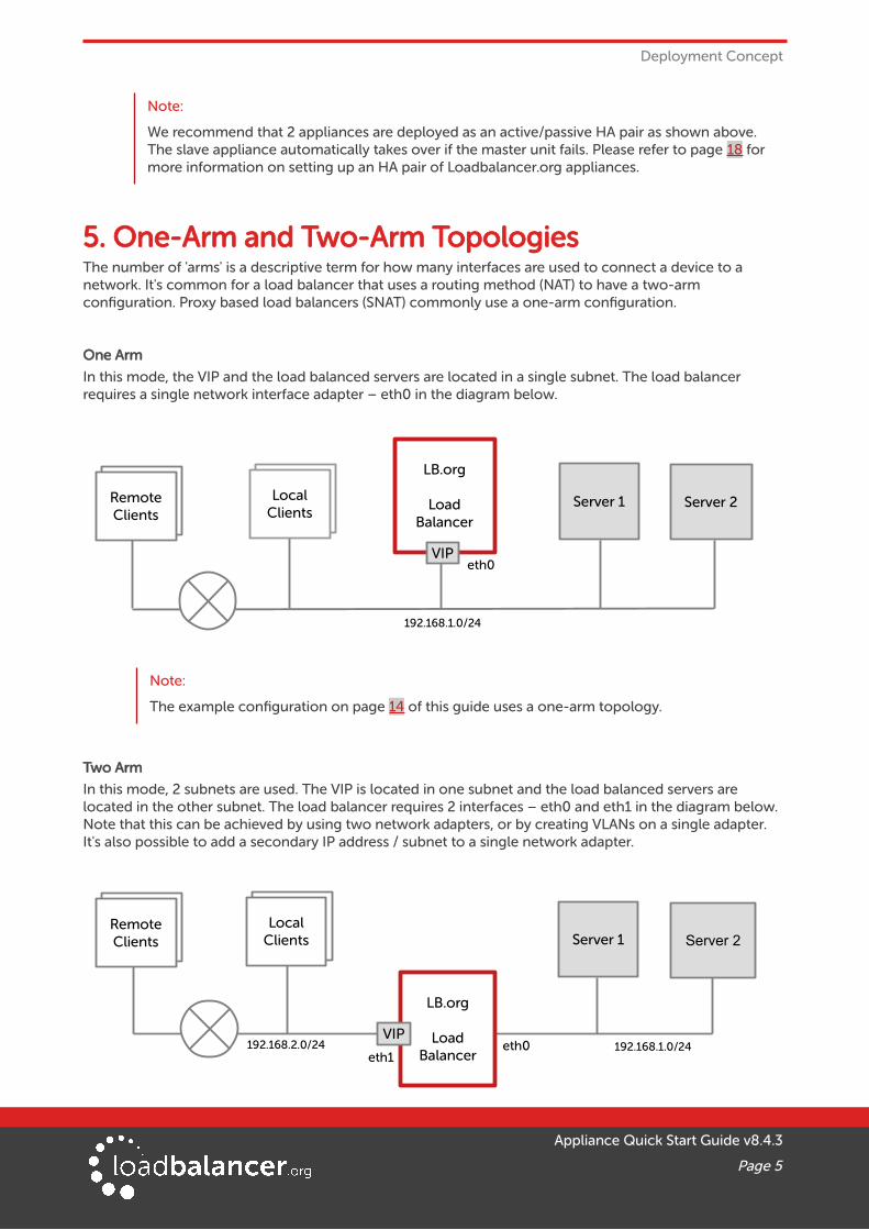
5. One-Arm and Two-Arm TopologiesThe number of 'arms' is a descriptive term for how many interfaces are used to connect a device to a network. It's common for a load balancer that uses a routing method (NAT) to have a two-arm configuration. Proxy based load balancers (SNAT) commonly use a one-arm configuration.
One Arm
In this mode, the VIP and the load balanced servers are located in a single subnet. The load balancer requires a single network interface adapter – eth0 in the diagram below.
Note:
The example configuration on page 14 of this guide uses a one-arm topology.
Two Arm
In this mode, 2 subnets are used. The VIP is located in one subnet and the load balanced servers are located in the other subnet. The load balancer requires 2 interfaces – eth0 and eth1 in the diagram below. Note that this can be achieved by using two network adapters, or by creating VLANs on a single adapter. It's also possible to add a secondary IP address / subnet to a single network adapter.
Appliance Quick Start Guide v8.4.3
Page 5
Server 1 Server 2
Server 1 Server 2
eth0
eth0eth1
192.168.1.0/24
192.168.1.0/24192.168.2.0/24
LB.org
LoadBalancer
LB.org
LoadBalancer
VIP
ClientsRemoteClients
ClientsLocalClients
ClientsRemoteClients
ClientsLocalClients
VIP

Load Balancing Methods
6. Load Balancing MethodsThe Loadbalancer.org appliance is one of the most flexible load balancers on the market. The design allows different load balancing modules to utilize the core high availability framework of the appliance. Multiple load balancing methods can be used at the same time or in combination with each other.
Layer 4 DR
(Direct Routing)
Ultra-fast local server based load balancing
- Requires solving the 'ARP problem'
on the Real Servers – please refer to theAdministration Manual (page 89) for more details
One-Arm (*)
Layer 4 NAT
(Network AddressTranslation)
Fast Layer 4 load balancing
- The appliance must be the default gateway forthe Real Servers
One or Two-Arm
Layer 4 TUN Similar to DR but works across IP encapsulatedtunnels
One-Arm
Layer 4 SNAT(Source Network
Address Translation)
Fast layer 4 SNAT supporting both TCP & UDP
- Requires no Real Server changes
One or Two-Arm
Layer 7 SSL Termination
(Pound & STunnel)
Usually required in order to process cookiepersistence in HTTPS streams on the load balancer
- SSL Termination is processor intensive
One or Two-Arm
Layer 7 SNAT
(Source NetworkAddress Translation
using HAProxy)
Layer 7 allows great flexibility including full SNATand remote server load balancing, cookie insertion
and URL switching
- Very simple to implement
- Requires no Real Server changes
- Not as fast as Layer 4 methods
One or Two-Arm
(*) DR mode can also be used in a multi-homed configuration where real servers are located in different subnets. In this case, the load balancer must have an interface in the same subnet to enable layer 2 connectivity which is required for DR mode to operate.
Key
Recommended for high performance fully transparent and scalable solutions
Recommended if HTTP cookie persistence is required, also used for several Microsoft applications such as Exchange, Sharepoint & Remote Desktop Services and for overall deployment simplicity since real servers can be on any accessible subnet and no Real-Server changes are required
Only required for Direct Routing implementation across routed networks (rarely used)
Recommended when you want to load balance both TCP and UDP but you're unable to use DR mode or NAT mode due to network topology or Real Server related reasons
Appliance Quick Start Guide v8.4.3
Page 6

Load Balancing Methods
Note:
Layer 7 SNAT mode is generally the simplest most flexible method to use. As mentioned above, it's not the fastest method but enables a robust load balancing solution to be rapidly deployed. This is illustrated by the simple example on page 14 of this guide.
Note:
Please refer to the Administration Manual (pages 26-32) for more detailed information on each load balancing method.
7. Appliance Deployment
VIRTUAL APPLIANCEThe VA is currently available for VMware, Virtual Box, Hyper-V, KVM, Nutanix and XEN and has been optimized for each Hypervisor. By default, the VA is allocated 1 CPU, 2GB of RAM and has an 8GB virtual disk.
Note:
The Virtual Appliance can be downloaded here.
Note:
Please refer to the Administration Manual (page 35) and the ReadMe.txt text file included in eachVA download for more detailed information on deploying the VA using various Hypervisors.
HARDWARE APPLIANCEFor details of all hardware models and information on installing and connecting the appliance, please referto the Hardware Installation Guide.
CLOUD APPLIANCE
AWSFor details of deploying and configuring the Amazon Web Services (AWS) appliance please refer to the AWS Quick Start Guide.
AZUREFor details of deploying and configuring the Microsoft Azure appliance please refer to the Azure Quick Start Guide.
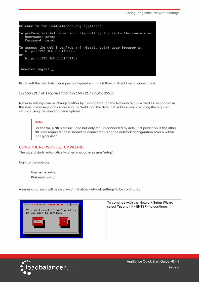
8. Configuring Initial Network SettingsAt power up the following startup message is displayed:
Appliance Quick Start Guide v8.4.3
Page 7
Configuring Initial Network Settings
By default the load balancer is pre-configured with the following IP address & subnet mask:
192.168.2.21 / 24 ( equivalent to : 192.168.2.21 / 255.255.255.0 )
Network settings can be changed either by running through the Network Setup Wizard as mentioned in the startup message or by accessing the WebUI on the default IP address and changing the required settings using the relevant menu options.
Note:
For the VA, 4 NICs are included but only eth0 is connected by default at power on. If the other NICs are required, these should be connected using the network configuration screen within the Hypervisor.
USING THE NETWORK SETUP WIZARDThe wizard starts automatically when you log in as user 'setup'.
login to the console:
Username: setup
Password: setup
A series of screens will be displayed that allow network settings to be configured:
To continue with the Network Setup Wizard select Yes and hit <ENTER> to continue.
Appliance Quick Start Guide v8.4.3
Page 8

Configuring Initial Network Settings
A list of available interfaces will be shown, hit <ENTER> to continue.
Select Yes If you want to configure a bonded interface, if not leave No selected, then hit <ENTER> to continue.
If you select Yes you’ll have two options:
bond eth0 and eth1
or
bond eth2 and eth3
Select Yes If you want to configure a VLAN, if not leave No selected, then hit <ENTER> to continue.
If you select Yes you’ll be prompted to enter a VLAN Tag ID.
Select the interface that will be used to manage the appliance, select Select and hit <ENTER> to continue.
Appliance Quick Start Guide v8.4.3
Page 9

Configuring Initial Network Settings
Enter the required management IP address and CIDR prefix, select Done and hit <ENTER> to continue.
NOTE: a subnet mask such as 255.255.255.0 is not valid, in this case enter 24 instead.
Enter the default gateway address, select Done and hit <ENTER> to continue.
Define the required DNS server(s), select Done and hit <ENTER> to continue.
A summary of all settings is displayed, if everything looks good hit <ENTER> to continue, all settings will then be applied.
At this stage you’ll be asked if you're recovering from node (i.e. master or slave) failure.
If you're simply deploying a new appliance, select No and hit <ENTER> to continue.
For more details on using the Peer Recovery feature, please refer to the Administration Manual (page 294).
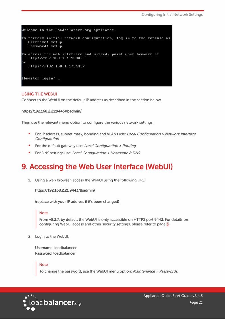
Once the wizard completes, the login prompt will be displayed along with a reminder of the new IP address and the URL to connect to the WebUI:
Appliance Quick Start Guide v8.4.3
Page 10
Configuring Initial Network Settings
USING THE WEBUIConnect to the WebUI on the default IP address as described in the section below.
https://192.168.2.21:9443/lbadmin/
Then use the relevant menu option to configure the various network settings:
• For IP address, subnet mask, bonding and VLANs use: Local Configuration > Network Interface Configuration
• For the default gateway use: Local Configuration > Routing
• For DNS settings use: Local Configuration > Hostname & DNS
9. Accessing the Web User Interface (WebUI)
1. Using a web browser, access the WebUI using the following URL:
https://192.168.2.21:9443/lbadmin/
(replace with your IP address if it's been changed)
Note:
From v8.3.7, by default the WebUI is only accessible on HTTPS port 9443. For details on configuring WebUI access and other security settings, please refer to page 3.
2. Login to the WebUI:
Username: loadbalancer
Password: loadbalancer
Note:
To change the password, use the WebUI menu option: Maintenance > Passwords.
Appliance Quick Start Guide v8.4.3
Page 11
Accessing the Web User Interface (WebUI)
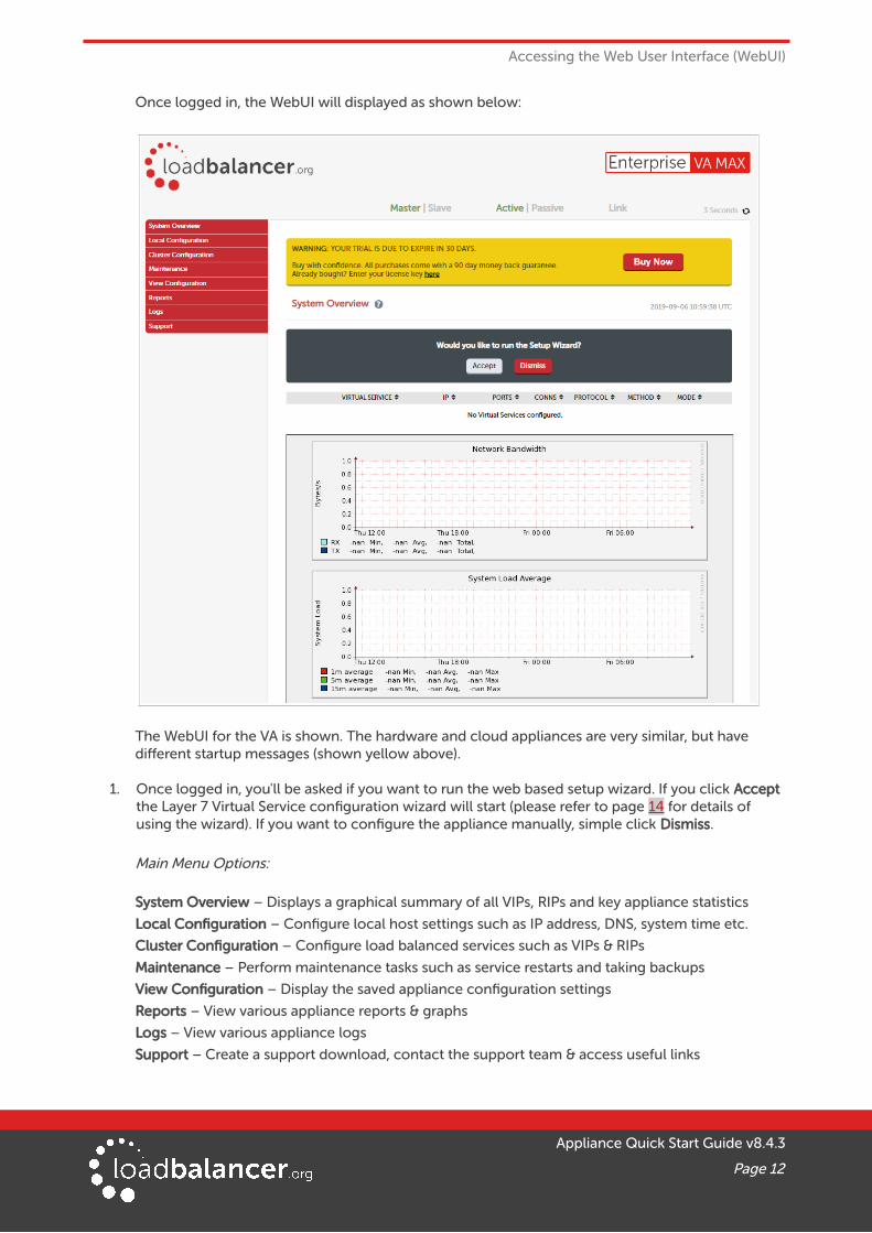
Once logged in, the WebUI will displayed as shown below:
The WebUI for the VA is shown. The hardware and cloud appliances are very similar, but have different startup messages (shown yellow above).
1. Once logged in, you'll be asked if you want to run the web based setup wizard. If you click Accept the Layer 7 Virtual Service configuration wizard will start (please refer to page 14 for details of using the wizard). If you want to configure the appliance manually, simple click Dismiss.
Main Menu Options:
System Overview – Displays a graphical summary of all VIPs, RIPs and key appliance statistics
Local Configuration – Configure local host settings such as IP address, DNS, system time etc.
Cluster Configuration – Configure load balanced services such as VIPs & RIPs
Maintenance – Perform maintenance tasks such as service restarts and taking backups
View Configuration – Display the saved appliance configuration settings
Reports – View various appliance reports & graphs
Logs – View various appliance logs
Support – Create a support download, contact the support team & access useful links
Appliance Quick Start Guide v8.4.3
Page 12

Ports Used by the Appliance
10. Ports Used by the ApplianceBy default, the appliance uses the following TCP & UDP ports:
Protocol Port Purpose
TCP 22 SSH
TCP 9080 WebUI – HTTP (disabled by default)
TCP 9081 Nginx fallback page
TCP 9443 WebUI – HTTPS
TCP 7777 HAProxy statistics page
TCP 7778 HAProxy persistence table replication
UDP 6694 Heartbeat between master & slave appliances in HA mode
11. LicensingThe trial runs for 30 days and is completely unrestricted during this time. After 30 days, the appliance continues to work but it's no longer possible to make changes to the configuration. If you need more time to complete your evaluation, please contact [email protected] who will be able to provide guidance on how to extend the trial using a simple command.
When a license is purchased, you'll be provided with a license key file by our sales team. You can then simply apply this license to your appliance.
To install the license:
1. Using the WebUI, navigate to: Local Configuration > License Key
2. Browse to the license file provided when the appliance was purchased
3. Click Install License Key
12. Software UpdatesLoadbalancer.org continually develop and add new and improved features to the appliance. These updatescan be applied during the trial to ensure you have the very latest version of our software for your evaluation.
To run Software Update:
1. Using the WebUI, navigate to: Maintenance > Software Update
2. Choose Online Update if the appliance has Internet access
3. If updates are available, you'll be presented with a list of changes, click the Online Update button at the bottom of the page to start the update
Note:
If your appliance does not have Internet access, please contact [email protected] for details of how to obtain the offline update files.
Appliance Quick Start Guide v8.4.3
Page 13
Configuring & Testing a Simple Load Balanced Test Environment
13. Configuring & Testing a Simple Load Balanced Test Environment
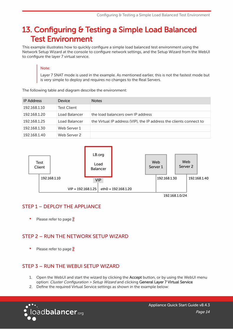
This example illustrates how to quickly configure a simple load balanced test environment using the Network Setup Wizard at the console to configure network settings, and the Setup Wizard from the WebUIto configure the layer 7 virtual service.
Note:
Layer 7 SNAT mode is used in the example. As mentioned earlier, this is not the fastest mode butis very simple to deploy and requires no changes to the Real Servers.
The following table and diagram describe the environment:
IP Address Device Notes
192.168.1.10 Test Client
192.168.1.20 Load Balancer the load balancers own IP address
192.168.1.25 Load Balancer the Virtual IP address (VIP), the IP address the clients connect to
192.168.1.30 Web Server 1
192.168.1.40 Web Server 2
STEP 1 – DEPLOY THE APPLIANCE
• Please refer to page 7
STEP 2 – RUN THE NETWORK SETUP WIZARD
• Please refer to page 7
STEP 3 – RUN THE WEBUI SETUP WIZARD
1. Open the WebUI and start the wizard by clicking the Accept button, or by using the WebUI menu option: Cluster Configuration > Setup Wizard and clicking General Layer 7 Virtual Service
2. Define the required Virtual Service settings as shown in the example below:
Appliance Quick Start Guide v8.4.3
Page 14
WebServer 1
WebServer 2
eth0 = 192.168.1.20
192.168.1.0/24
LB.org
LoadBalancer
VIP
TestClient
192.168.1.10 192.168.1.40192.168.1.30
VIP = 192.168.1.25

Configuring & Testing a Simple Load Balanced Test Environment
3. Click Create Virtual Service
4. Now continue and add the associated load balanced servers (Real Servers) as shown below:
• Use the Add Real Server button to define additional Real Servers and use the red cross to delete Real Servers
• Once you're happy, click Attach Real Servers to create the new Virtual Service & Real Servers
• A confirmation message will be displayed as shown in the example below:
Appliance Quick Start Guide v8.4.3
Page 15

Configuring & Testing a Simple Load Balanced Test Environment
5. Click Continue
6. Finally, reload HAProxy using the Reload HAProxy button in the blue box at the top of the screen orby using the WebUI menu option: Maintenance > Restart Services and clicking Reload HAProxy
Note:
Running the wizard again will permit additional Layer 7 VIPs and associated RIPs to be defined.
Note:
To restore manufacturer's settings use the WebUI menu option: Maintenance > Backup & Restore > Restore Manufacturer's Defaults. This will reset the IP address to 192.168.2.21/24.
Note:
By default Real Server health-checks set as a TCP port connect. If you need a more robust check, this can be changed by modifying the configuration as explained below. Please refer to the Administration Manual (page 201) for more information on configuring health-checks.
STEP 4 – VIEWING & MODIFYING THE CONFIGURATION
1. The VIP created by the wizard can be seen using the WebUI menu option: Cluster Configuration > Layer 7 – Virtual Services as shown below:
2. Clicking the Modify button allows all VIP setting to be modified
3. If changes are made, click the Update button to save the changes, then use the Reload HAProxy button at the top of the screen to apply the changes
4. Additional VIPs can be added by running the Setup Wizard again, or by clicking the Add a new Virtual Service button to define the VIP manually
Appliance Quick Start Guide v8.4.3
Page 16
Configuring & Testing a Simple Load Balanced Test Environment
Note:
Real Servers can be added manually using the WebUI menu option: Cluster Configuration > Layer 7 – Real Servers.
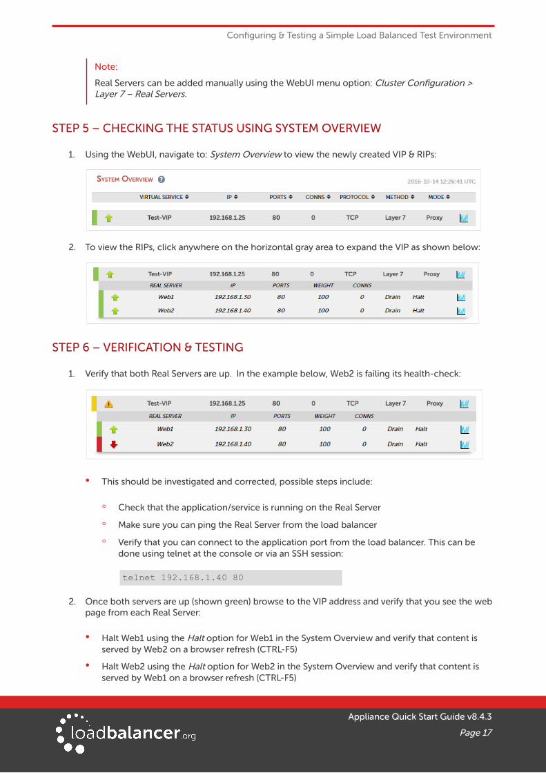
STEP 5 – CHECKING THE STATUS USING SYSTEM OVERVIEW
1. Using the WebUI, navigate to: System Overview to view the newly created VIP & RIPs:
2. To view the RIPs, click anywhere on the horizontal gray area to expand the VIP as shown below:
STEP 6 – VERIFICATION & TESTING
1. Verify that both Real Servers are up. In the example below, Web2 is failing its health-check:
• This should be investigated and corrected, possible steps include:
◦ Check that the application/service is running on the Real Server
◦ Make sure you can ping the Real Server from the load balancer
◦ Verify that you can connect to the application port from the load balancer. This can be done using telnet at the console or via an SSH session:
telnet 192.168.1.40 80
2. Once both servers are up (shown green) browse to the VIP address and verify that you see the webpage from each Real Server:
• Halt Web1 using the Halt option for Web1 in the System Overview and verify that content is served by Web2 on a browser refresh (CTRL-F5)
• Halt Web2 using the Halt option for Web2 in the System Overview and verify that content is served by Web1 on a browser refresh (CTRL-F5)
Appliance Quick Start Guide v8.4.3
Page 17

Configuring & Testing a Simple Load Balanced Test Environment
Note:
Please refer to the Administration Manual (page 246-261) for more configuration examples using Layer 7 SNAT mode and also Layer 4 DR mode, Layer 4 NAT mode & Layer 4 SNAT mode.
Note:
For more information on verifying your test environment and ways to diagnose any issues you have, please also refer to Chapter 12 – Testing Load Balanced Services in the Administration Manual (page 263 – 268).
14. Configuring HA – Adding a Slave ApplianceAs mentioned earlier, our recommended configuration is to use a clustered HA pair of load balancers to provide a highly available and resilient load balancing solution. We recommend that the master is fully configured first, then the slave should be added. The clustered HA pair uses Heartbeat to determine the state of the other appliance. Should the active device (normally the master) suffer a failure, the passive device (normally the slave) will take over.
To add a slave node – i.e. create a highly available clustered pair:
1. Deploy a second appliance that will be the slave and configure initial network settings
2. Using the WebUI, navigate to: Cluster Configuration > High-Availability Configuration
3. Specify the IP address and the loadbalancer users password (the default is 'loadbalancer') for the slave (peer) appliance as shown above
4. Click Add new node
5. The pairing process now commences as shown below:
Appliance Quick Start Guide v8.4.3
Page 18

Configuring HA – Adding a Slave Appliance
6. Once complete, the following will be displayed:
7. To finalize the configuration, restart heartbeat and any other services as prompted in the blue message box at the top of the screen
Note:
Clicking the Restart Heartbeat button on the master appliance will also automatically restart heartbeat on the slave appliance.
Note:
Please refer to the Administration Manual (page 221-234) for more detailed information on configuring HA with 2 appliances.
15. More InformationPlease refer to our website for the latest administration manual, deployment guides and all other documentation: https://www.loadbalancer.org/support/manuals/.
16. Loadbalancer.org Technical SupportIf you have any questions regarding the appliance or how to load balance your application, please don't hesitate to contact our support team using the following email address: [email protected]
Appliance Quick Start Guide v8.4.3
Page 19

Company Contact Information
17. Company Contact Information
Website URL: w w w.loadbalancer.org
North America (US) Loadbalancer.org, Inc.
4550 Linden Hill Road, Suite 201Wilmington, DE 19808USA
Tel:Email (sales):
Email (support):
+1 [email protected]@loadbalancer.org
North America (Canada) Loadbalancer.org Appliances Ltd.300-422 Richards StreetVancouver, BCV6B 2Z4Canada
Tel:Email (sales):
Email (support):
+1 [email protected]@loadbalancer.org
Europe (UK) Loadbalancer.org Ltd.Compass HouseNorth Harbour Business ParkPortsmouth, PO6 4PSUK
Tel:Email (sales):
Email (support):
+44 (0)330 380 [email protected]@loadbalancer.org
Europe (Germany) Loadbalancer.org GmbHTengstraße 2780798MünchenGermany
Tel:Email (sales):
Email (support):
+49 (0)89 2000 [email protected]@loadbalancer.org
Appliance Quick Start Guide v8.4.3
Page 20