Embed Size (px)
Citation preview
Appendix L Proposed Changes to Section 5 of the
AASHTO LRFD Specification
SECTION 5: CONCRETE STRUCTURES PROPOSED CHANGES
5-i
5 NOTE: THIS CONTAINS THE PROPOSED CHANGES TO SECTION 5 OF THE AASHTO LRFD
SEPCIFICATIONS (V5). ONLY AFFECTED SECTIONS ARE SHOWN. IN THE CASES OF LARGE SECTIONS WHERE THERE ARE MINOR MODIFICATIONS, ONLY THE MODIFICATIONS ARE SHOWN FOR CLARITY. MODIFIED ARTICLES ARE SHOWN IN BOLD IN THE TABLE OF CONTENTS.
5.2—DEFINITIONS......................................................................................................................................................5-3!5.3—NOTATION ..........................................................................................................................................................5-3!
5.4.3—Reinforcing Steel ........................................................................................................................................5-3!5.4.3.1—General..............................................................................................................................................5-3!5.4.3.2—Modulus of Elasticity........................................................................................................................5-3!5.4.3.3—Special Applications .........................................................................................................................5-3!
5.5.3—Fatigue Limit State......................................................................................................................................5-4!5.5.3.1—General..............................................................................................................................................5-4!5.5.3.2—Reinforcing Bars ...............................................................................................................................5-5!5.5.4.2—Resistance Factors ............................................................................................................................5-6!
5.5.4.2.1—Conventional Construction .....................................................................................................5-6!5.7—DESIGN FOR FLEXURAL AND AXIAL FORCE EFFECTS...........................................................................5-9!
5.7.1—Assumptions for Service and Fatigue Limit States.....................................................................................5-9!5.7.2—Assumptions for Strength and Extreme Event Limit States .......................................................................5-9!
5.7.2.1—General..............................................................................................................................................5-9!5.7.3.2—Flexural Resistance .........................................................................................................................5-12!
5.7.3.2.5—Strain Compatibility Approach.............................................................................................5-12!5.7.3.3—Limits for Reinforcement ...............................................................................................................5-13!
5.7.3.3.1—Maximum Reinforcement.....................................................................................................5-13!5.7.3.4—Control of Cracking by Distribution of Reinforcement..................................................................5-13!5.7.3.5—Moment Redistribution ...................................................................................................................5-15!5.7.4.2—Limits for Reinforcement ...............................................................................................................5-16!5.7.4.4—Factored Axial Resistance ..............................................................................................................5-17!5.7.4.6—Spirals and Ties...............................................................................................................................5-18!
5.8—SHEAR AND TORSION....................................................................................................................................5-19!5.8.2.4—Regions Requiring Transverse Reinforcement ...............................................................................5-19!5.8.2.5—Minimum Transverse Reinforcement .............................................................................................5-19!5.8.2.7—Maximum Spacing of Transverse Reinforcement ..........................................................................5-20!5.8.2.8—Design and Detailing Requirements ...............................................................................................5-21!5.8.3.3—Nominal Shear Resistance ..............................................................................................................5-21!5.8.3.5—Longitudinal Reinforcement ...........................................................................................................5-23!
5.8.4—Interface Shear Transfer—Shear Friction .................................................................................................5-24!5.8.4.1—General............................................................................................................................................5-24!
5.10—DETAILS OF REINFORCEMENT .................................................................................................................5-25!5.10.1—Concrete Cover .......................................................................................................................................5-25!5.10.2—Hooks and Bends ....................................................................................................................................5-25!
5.10.2.1—Standard Hooks.............................................................................................................................5-25!5.10.2.2—Seismic Hooks ..............................................................................................................................5-26!
5.10.6—Transverse Reinforcement for Compression Members ..........................................................................5-26!5.10.6.1—General..........................................................................................................................................5-26!5.10.11.1—General........................................................................................................................................5-27!
5.10.11.4.1d—Transverse Reinforcement for Confinement at Plastic Hinges ...............................5-28!5.11—DEVELOPMENT AND SPLICES OF REINFORCEMENT ..........................................................................5-30!
5.11.1—General ....................................................................................................................................................5-30!5.11.1.1—Basic Requirements ......................................................................................................................5-30!
5.11.2—Development of Reinforcement ..............................................................................................................5-30!5.11.2.1—Deformed Bars and Deformed Wire in Tension...........................................................................5-31!5.11.2.4—Standard Hooks in Tension...........................................................................................................5-31!
5.11.5—Splices of Bar Reinforcement .................................................................................................................5-31!5.11.5.3—Splices of Reinforcement in Tension............................................................................................5-31!

5-ii AASHTO LRFD BRIDGE DESIGN SPECIFICATIONS
5.11.5.3.1—Lap Splices in Tension....................................................................................................... 5-32!5.11.5.3.2—Mechanical Connections or Welded Splices in Tension.................................................... 5-32!
5.15—REFERENCES ................................................................................................................................................. 5-33!
TABLE OF CONTENTS 5-3
5.2—DEFINITIONS Tension-Controlled Section—A cross-section in which the net tensile strain in the extreme tension steel at nominal resistance is greater than or equal to 0.005 the tension-controlled strain limit. Tension-Controlled Strain Limit—The net tensile strain in the extreme tension steel at nominal resistance that results in a tension-controlled section. See Article 5.7.2.1. 5.3—NOTATION fy = specified minimum yield strength of reinforcing bars (ksi); specified yield strength of reinforcing bars !75
ksi (5.5.4.2.1) (5.10.8) unless higher strength is permitted by a specific article (5.4.3.1) !cl = compression-controlled strain limit in the extreme tension steel (in./in.) (5.7.2.1) !tl = tension-controlled strain limit in the extreme tension steel (in./in.) (5.7.2.1)
5.4.3—Reinforcing Steel
5.4.3.1—General Reinforcing bars, deformed wire, cold-drawn wire,
welded plain wire fabric, and welded deformed wire fabric shall conform to the material standards as specified in Article 9.2 of the AASHTO LRFD Bridge Construction Specifications.
C5.4.3.1
Reinforcement shall be deformed, except that plain bars or plain wire may be used for spirals, hoops, and wire fabric.
The nominal yield strength shall be the minimum as specified for the grade of steel selected, except that yield strengths in excess of 75.0 ksi shall not be used for design purposes unless specified yield strengths up to 100.0 ksi are permitted by specific articles for Seismic Zone 1. The yield strength or grade of the bars or wires shall be shown in the contract documents. Bars with yield strengths less than 60.0 ksi shall be used only with the approval of the Owner.
Unlike reinforcing bars with yield strengths below 75.0 ksi, reinforcing bars with yield strengths exceeding 75.0 ksi usually do not have well-defined yield plateaus. Consequently, different methods are used in different standards to establish yield strengths. These include the 0.2% offset and the 0.35% or 0.50% extension methods. For design purposes, the value of fy should be the same as the specified yield strength defined in the material standard. Based on research by Shahrooz et al. (2010), certain articles now allow the use of reinforcing steels with yield strengths up to 100.0 ksi for Seismic Zone 1.
Where ductility is to be assured or where welding is
required, steel conforming to the requirements of ASTM A706, “Low Alloy Steel Deformed Bars for Concrete Reinforcement,” should be specified.
ASTM A706 reinforcement should be considered for seismic design because of the greater quality control by which unanticipated overstrength is limited.
5.4.3.2—Modulus of Elasticity The modulus of elasticity, Es, of steel reinforcing
reinforcement shall be assumed as 29,000 ksi for specified yield strengths up to 100 ksi.
5.4.3.3—Special Applications Reinforcement to be welded shall be indicated in
the contract documents, and the welding procedure to be
C5.4.3.3 In 2004, ASTM published A1035/A1035M,
Standard Specification for Deformed and Plain, Low-
5-4 AASHTO LRFD BRIDGE DESIGN SPECIFICATIONS used shall be specified.
The use of reinforcing steel with specified yield strengths of less than or equal to 100.0 ksi may be used for Seismic Zone 1 where permitted by specific articles. Reinforcement conforming to ASTM A1035/A1035M may only be used as top and bottom flexural reinforcement in the longitudinal and transverse directions of bridge decks in Seismic Zones 1and 2.
carbon, Chromium, Steel Bars for Concrete Reinforcement. This reinforcement offers the potential for corrosion resistance.
Epoxy-coated reinforcing steel provides a physical barrier to inhibit corrosion of the steel in the presence of chlorides. The handling, placement, and repair of epoxy-coated reinforcing steel requires significant care and attention.
Reinforcement conforming to ASTM A1035/ A1035M has a specified minimum yield strength of 100 ksi determined by the 0.2 percent offset method, a specified minimum tensile strength of 150 ksi, and a specified minimum elongation of six or seven percent depending on bar size. There is also a requirement that the stress corresponding to a tensile strain of 0.0035 shall be a minimum of 80 ksi. The reinforcement has a non-linear stress-strain relationship. Article 5.4.3.1 of the Design Specifications states that yield strengths in excess of 75.0 ksi shall not be used for design purposes. Consequently, design is based on a stress of 75.0 ksi, but the actual strength is at least twice that value. This has lead to concerns about the applicability of the existing specifications with ASTM A1035 reinforcement. Consequently, it is proposed that initial usage of the reinforcement be restricted to top and bottom flexural reinforcement in the transverse and longitudinal directions of bridge decks in Seismic Zones 1 and 2.
5.5.3—Fatigue Limit State
5.5.3.1—General Fatigue need not be investigated for concrete deck
slabs in multigirder applications or reinforced-concrete box culverts.
C5.5.3.1 Stresses measured in concrete deck slabs of bridges
in service are far below infinite fatigue life, most probably due to internal arching action; see Article C9.7.2.
Fatigue evaluation for reinforced-concrete box culverts showed that the live load stresses in the reinforcement due to Fatigue I load combination did not reduce the member resistance at the strength limit state.
In regions of compressive stress due to permanent loads and prestress in reinforced and partially prestressed concrete components, fatigue shall be considered only if this compressive stress is less than the maximum tensile live load stress resulting from the Fatigue I load combination as specified in Table 3.4.1-1 in combination with the provisions of Article 3.6.1.4.
In determining the need to investigate fatigue, Table 3.4.1-1 specifies a load factor of 1.50 on the live load force effect resulting from the fatigue truck for the Fatigue I load combination. This factored live load force effect represents the greatest fatigue stress that the bridge will experience during its life.
Fatigue of the reinforcement need not be checked for fully prestressed components designed to have extreme fiber tensile stress due to Service III Limit State within the tensile stress limit specified in Table 5.9.4.2.2-1.
Fatigue limit state load factor, girder distribution factors, and dynamic allowance cause fatigue limit state stress to be considerably less than the corresponding value determined from Service Limit State III. For fully prestressed components, the net concrete stress is usually significantly less than the concrete tensile stress limit specified in Table 5.9.4.2.2-1. Therefore, the calculated flexural stresses are significantly reduced. For this situation, the calculated steel stress range, which is equal to the modular ratio times the concrete stress range, is almost always less than the steel fatigue stress range limit specified in Article 5.5.3.3.
TABLE OF CONTENTS 5-5
For fatigue considerations, concrete members shall satisfy:
(5.5.3.1-1)
where: " = load factor specified in Table 3.4.1-1 for
the Fatigue I load combination #f = force effect, live load stress range due to
the passage of the fatigue load as specified in Article 3.6.1.4 (ksi)
(#F)TH = constant-amplitude fatigue threshold, as
specified in Article 5.5.3.2, 5.5.3.3, or 5.5.3.4, as appropriate (ksi)
For fully prestressed components in other than segmentally constructed bridges, the compressive stress due to the Fatigue I load combination and one-half the sum of effective prestress and permanent loads shall not exceed 0.40f "c after losses.
The section properties for fatigue investigations shall be based on cracked sections where the sum of stresses, due to unfactored permanent loads and prestress, and the Fatigue I load combination is tensile and exceeds 0.095$f "c.
5.5.3.2—Reinforcing Bars The constant-amplitude fatigue threshold, (#F)TH,
for straight reinforcement and welded wire reinforcement without a cross weld in the high-stress region shall be taken as:
(5.5.3.2-1)
The constant-amplitude fatigue threshold, (#F)TH,
for straight welded wire reinforcement with a cross weld in the high-stress region shall be taken as:
(5.5.3.2-2)
where: fmin = minimum live-load stress resulting from the
Fatigue I load combination, combined with the more severe stress from either the permanent loads or the permanent loads, shrinkage, and creep-induced external loads; positive if tension, negative if compression (ksi)
fy = specified minimum yield strength, not to be
C5.5.3.2 With the permitted use of steel reinforcement
having yield stresses above 75.0 ksi, the value of fmin is expected to increase. In previous versions of Eq. 5.5.3.2-1, an increase in fmin would result in an decrease in (#F)TH, regardless of the yield strength of the bar. All available data indicates that steel with a higher yield strength actually has a higher fatigue limit (DeJong and MacDougall, 2006). Eq. 5.5.3.2-1 has been calibrated such that there is no change to the value of (#F)TH from earlier versions of this equation for cases of fy = 60.0 ksi, but it now provides more reasonable values of (#F)TH for higher strength reinforcing bars.
Bends in primary reinforcement should be avoided in regions of high stress range.
Structural welded wire reinforcement has been increasingly used in bridge applications in recent years, especially as auxiliary reinforcement in bridge I- and box beams and as primary reinforcement in slabs. Design for shear has traditionally not included a fatigue check of the reinforcement as the member is expected to be uncracked under service conditions and the stress range in steel minimal. The stress range for steel bars has existed in previous editions. It is based on Hansen et al. (1976). The simplified form in this edition replaces the (r/h) parameter with the default value 0.3
5-6 AASHTO LRFD BRIDGE DESIGN SPECIFICATIONS
taken less than 60.0 ksi nor greater than 100.0 ksi.
The definition of the high-stress region for application of Eqs. 5.5.3.2-1 and 5.5.3.2-2 for flexural reinforcement shall be taken as one-third of the span on each side of the section of maximum moment.
recommended by Hansen et al. Inclusion of limits for WWR is based on recent studies by Hawkins et al. (1971, 1987) and Tadros et al. (2004).
Since the fatigue provisions were developed based primarily on ASTM A615 steel reinforcement, their applicability to other types of reinforcement is largely unknown. Consequently, a cautionary note is added to the Commentary.
5.5.4.2—Resistance Factors 5.5.4.2.1—Conventional Construction The provisions of Article 5.5.4.2.1 are applicable to
nonprestressed reinforcing steels with specified yield strengths up to 100.0 ksi for Seismic Zone 1.
Resistance factor $ shall be taken as:
• For tension-controlled reinforced concrete sections as defined in Article 5.7.2.1.................. 0.90
• For tension-controlled prestressed concrete sections as defined in Article 5.7.2.1.................. 1.00
• For shear and torsion: normal weight concrete........................ 0.90 lightweight concrete............................. 0.70 • For compression-controlled sections with
spirals or ties, as defined in Article 5.7.2.1, except as specified in Articles 5.10.11.3 and 5.10.11.4.1b for Seismic Zones 2, 3, and 4 at the extreme event limit state... 0.75
• For bearing on concrete...................................... 0.70 • For compression in strut-and-tie models ............ 0.70
C5.5.4.2.1 In applying the resistance factors for tension-
controlled and compression-controlled sections, the axial tensions and compressions to be considered are those caused by external forces. Effects of prestressing forces are not included.
In editions of and interims to the LRFD Specifications prior to 2005, the provisions specified the magnitude of the resistance factor for cases of axial load or flexure, or both, it terms of the type of loading. For these cases, the $-factor is now determined by the strain conditions at a cross-section, at nominal strength. The background and basis for these provisions are given in Mast (1992) and ACI 318-02.
A lower $-factor is used for compression-controlled sections than is used for tension-controlled sections because compression-controlled sections have less ductility, are more sensitive to variations in concrete strength, and generally occur in members that support larger loaded areas than members with tension-controlled sections.
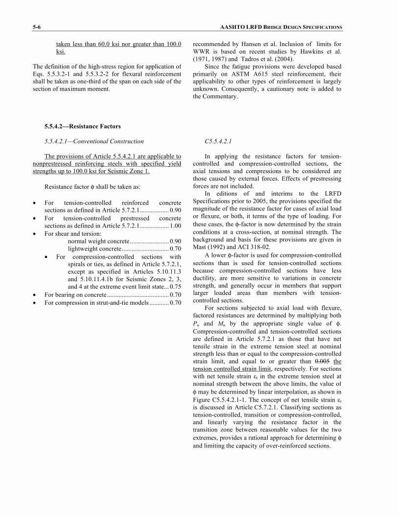
For sections subjected to axial load with flexure, factored resistances are determined by multiplying both Pn and Mn by the appropriate single value of $. Compression-controlled and tension-controlled sections are defined in Article 5.7.2.1 as those that have net tensile strain in the extreme tension steel at nominal strength less than or equal to the compression-controlled strain limit, and equal to or greater than 0.005 the tension controlled strain limit, respectively. For sections with net tensile strain %t in the extreme tension steel at nominal strength between the above limits, the value of $ may be determined by linear interpolation, as shown in Figure C5.5.4.2.1-1. The concept of net tensile strain %t is discussed in Article C5.7.2.1. Classifying sections as tension-controlled, transition or compression-controlled, and linearly varying the resistance factor in the transition zone between reasonable values for the two extremes, provides a rational approach for determining $ and limiting the capacity of over-reinforced sections.
TABLE OF CONTENTS 5-7
Figure C5.5.4.2.1-1—Variation of $ with Net Tensile Strain %t and dt /c for Grade 60 Nonprestressed Reinforcement and for Prestressing Steel • For compression in anchorage zones:
normal weight concrete ....................... 0.80 lightweight concrete ............................ 0.65
• For tension in steel in anchorage zones ............. 1.00 • For resistance during pile driving ...................... 1.00
For sections in which the net tensile strain in the
extreme tension steel at nominal resistance is between the limits for compression-controlled and tension-controlled sections, $ may be linearly increased from 0.75 to that for tension-controlled sections as the net
The $-factor of 0.8 for normal weight concrete reflects the importance of the anchorage zone, the brittle failure mode for compression struts in the anchorage zone, and the relatively wide scatter of results of experimental anchorage zone studies. The $-factor of 0.65 for lightweight concrete reflects its often lower tensile strength and is based on the multipliers used in ACI 318-89, Section 11.2.1.2.
The design of intermediate anchorages, anchorages, diaphragms, and multiple slab anchorages are addressed in Breen et al. (1994).
5-8 AASHTO LRFD BRIDGE DESIGN SPECIFICATIONS
tensile strain in the extreme tension steel increases from the compression-controlled strain limit, ! cl, to 0.005the tension-controlled strain limit, !tl.
This variation $ may be computed for prestressed members such that:
(5.5.4.2.1-1)
and for nonprestressed members such that:
(5.5.4.2.1-2)
where: c = distance from the extreme compression fiber to
the neutral axis(in.) dt = distance from the extreme compression fiber to
the centroid of the extreme tension steel element (in.)
!t = net tensile strain in the extreme tension steel at
nominal resistance !cl = compression-controlled strain limit in the
extreme tension steel (in./in.) (5.7.2.1) !tl = tension-controlled strain limit in the extreme
tension steel (in./in.) (5.7.2.1).
For tension-controlled partially prestressed components in flexure, the values of $ may be taken as:
(5.5.4.2.1-3)
in which:
(5.5.4.2.1-4)
where: PPR = partial prestress ratio As = area of nonprestressed tension
reinforcement (in.2) Aps = area of prestressing steel (in.2)
TABLE OF CONTENTS 5-9
fy = specified yield strength of reinforcing bars
(ksi) fpy = yield strength of prestressing steel (ksi)
Resistance factors shall not be applied to the
development and splice lengths of reinforcement as specified in Article 5.11.
5.7—DESIGN FOR FLEXURAL AND AXIAL FORCE EFFECTS
C5.7
The provisions of this article are applicable to
nonprestressed reinforcing steels with specified yield strengths up to 100.0 ksi for Seismic Zone 1.
The provisions for the use of reinforcing steel with specified yield strengths between 75.0 and 100.0 ksi are based on research by Shahrooz, et al. (2010), which did not consider seismic design.
5.7.1—Assumptions for Service and Fatigue Limit States
The following assumptions may be used in the
design of reinforced, prestressed, and partially prestressed concrete components for all compressive strength levels:
• Prestressed concrete resists tension at sections that
are uncracked, except as specified in Article 5.7.6.
• The strains in the concrete vary linearly, except in components or regions of components for which conventional strength of materials is inappropriate.
C5.7.1 Prestressing is treated as part of resistance, except
for anchorages and similar details, where the design is totally a function of the tendon force and for which a load factor is specified in Article 3.4.3. External reactions caused by prestressing induce force effects that normally are taken to be part of the loads side of Eq. 1.3.2.1-1. This represents a philosophical dichotomy. In lieu of more precise information, in these Specifications the load factor for these induced force effects should be taken as that for the permanent loads.
Examples of components for which the assumption of linearly varying strains may not be suitable include deep components such as deep beams, corbels, and brackets.
• The modular ratio, n, is rounded to the nearest integer number.
• The modular ratio is calculated as follows:
o Es /Ec for reinforcing bars
o Ep /Ec for prestressing tendons
• An effective modular ratio of 2n is applicable to permanent loads and prestress.
5.7.2—Assumptions for Strength and Extreme Event Limit States
5.7.2.1—General Factored resistance of concrete components shall be
based on the conditions of equilibrium and strain compatibility, the resistance factors as specified in Article 5.5.4.2, and the following assumptions: • In components with fully bonded reinforcement or
prestressing, or in the bonded length of locally debonded or shielded strands, strain is directly
C5.7.2.1 The first paragraph of C5.7.1 applies.
5-10 AASHTO LRFD BRIDGE DESIGN SPECIFICATIONS
proportional to the distance from the neutral axis, except for deep members that shall satisfy the requirements of Article 5.13.2, and for other disturbed regions.
• In components with fully unbonded or partially unbonded prestressing tendons, i.e., not locally debonded or shielded strands, the difference in strain between the tendons and the concrete section and the effect of deflections on tendon geometry are included in the determination of the stress in the tendons.
• If the concrete is unconfined, the maximum usable strain at the extreme concrete compression fiber is not greater than 0.003.
• If the concrete is confined, a maximum usable strain exceeding 0.003 in the confined core may be utilized if verified. Calculation of the factored resistance shall consider that the concrete cover may be lost at strains compatible with those in the confined concrete core.
• Except for the strut-and-tie model, the stress in the reinforcement is based on a stress-strain curve representative of the steel or on an approved mathematical representation, including development of reinforcing and prestressing elements and transfer of pretensioning.
• The tensile strength of the concrete is neglected.
• The concrete compressive stress-strain distribution is assumed to be rectangular, parabolic, or any other shape that results in a prediction of strength in substantial agreement with the test results.
• The development of reinforcing and prestressing elements and transfer of pretensioning are considered.
Research by Bae and Bayrak (2003) has shown that, for well-confined High Strength Concrete (HSC) columns, the concrete cover may be lost at maximum useable strains at the extreme concrete compression fiber as low as 0.0022. The heavy confinement steel causes a weak plane between the concrete core and cover, causing high shear stresses and the resulting early loss of concrete cover.
• Balanced strain conditions exist at a cross-section when tension reinforcement reaches the strain corresponding to its specified yield strength fy just as the concrete in compression reaches its assumed ultimate strain of 0.003.
• Sections are compression-controlled when the net tensile strain in the extreme tension steel is equal to or less than the compression-controlled strain limit, !cl, at the time the concrete in compression reaches its assumed strain limit of 0.003. The compression-controlled strain limit is the net tensile strain in the reinforcement at balanced strain conditions. For Grade 60 reinforcement, and for all prestressed reinforcement, the compression-controlled strain limit may be set equal to 0.002.!cl = 0.002. For nonprestressed reinforcing steel with a specified yield strength of 100.0 ksi, the compression-controlled strain limit may be taken as !cl = 0.004. For nonprestressed reinforcing steel with a specified
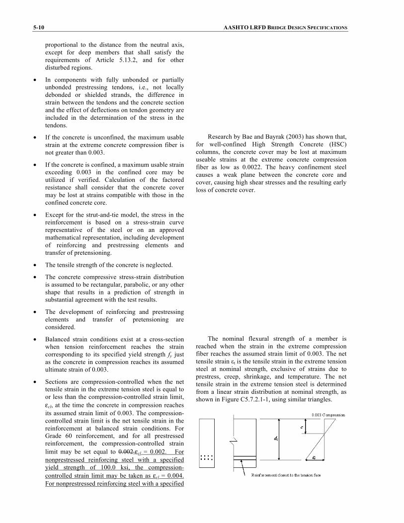
The nominal flexural strength of a member is reached when the strain in the extreme compression fiber reaches the assumed strain limit of 0.003. The net tensile strain %t is the tensile strain in the extreme tension steel at nominal strength, exclusive of strains due to prestress, creep, shrinkage, and temperature. The net tensile strain in the extreme tension steel is determined from a linear strain distribution at nominal strength, as shown in Figure C5.7.2.1-1, using similar triangles.
TABLE OF CONTENTS 5-11
yield strength between 60.0 and 100.0 ksi, the compression controlled strain limit may be determined by linear interpolation based on specified yield strength.
• Sections are tension-controlled when the net tensile strain in the extreme tension steel is equal to or greater than 0.005the tension-controlled strain limit, !tl just as the concrete in compression reaches its assumed strain limit of 0.003. Sections with net tensile strain in the extreme tension steel between the compression-controlled strain limit and 0.005 constitute a transition region between compression-controlled and tension-controlled sections the tension-controlled strain limit constitute a transition region between compression-controlled and tension-controlled sections. The tension-controlled strain limit, !tl, shall be taken as 0.005 for nonprestressed reinforcing steel with a specified yield strength, fy ! 75.0 ksi and prestressed reinforcing steel. The tension-controlled strain limit, !tl, shall be taken as 0.008 for nonprestressed reinforcing steel with a specified yield strength, fy = 100.0 ksi. For nonprestressed reinforcing steel with a specified yield strength between 75.0 and 100.0 ksi, the tension-controlled strain limit shall be determined by linear interpolation based on specified yield strength.
Figure C5.7.2.1-1—Strain Distribution and Net Tensile Strain
When the net tensile strain in the extreme tension
steel is sufficiently large (equal to or greater than 0.005the tension-controlled strain limit), the section is defined as tension-controlled where ample warning of failure with excessive deflection and cracking may be expected. When the net tensile strain in the extreme tension steel is small (less than or equal to the compression-controlled strain limit), a brittle failure condition may be expected, with little warning of impending failure. Flexural members are usually tension-controlled, while compression members are usually compression-controlled. Some sections, such as those with small axial load and large bending moment, will have net tensile strain in the extreme tension steel between the above limits. These sections are in a transition region between compression- and tension-controlled sections. Article 5.5.4.2.1 specifies the appropriate resistance factors for tension-controlled and compression-controlled sections, and for intermediate cases in the transition region.
Before the development of these provisions, the limiting tensile strain for flexural members was not stated, but was implicit in the maximum reinforcement limit that was given as c/de % 0.42, which corresponded to a net tensile strain at the centroid of the tension reinforcement of 0.00414. The net tensile strain limit of 0.005 for tension-controlled sections was chosen to be a single value that applies to all types of steel (prestressed and nonprestressed) permitted by this Specification. nonprestressed reinforcing steel with a specified yield strength of 75.0 ksi or less and prestressed reinforcing steel. Research by Shahrooz, et al. (2010) and Mast (2008) supports the values stated for compression- and tension-controlled strain limits for steel with higher specified yield strengths.
Unless unusual amounts of ductility are required, the 0.005tension-controlled strain limit will provide ductile behavior for most designs. One condition where greater ductile behavior is required is in design for redistribution of moments in continuous members and frames. Article 5.7.3.5 permits redistribution of negative moments. Since moment redistribution is dependent on adequate ductility in hinge regions, moment redistribution is limited to sections that have a net tensile strain of at least 0.00751.5!cl. For beams with compression reinforcement, or T-beams, the effects of compression reinforcement and flanges are automatically accounted for in the computation of net tensile strain %t.
• In the approximate flexural resistance equations of
Articles 5.7.3.1 and 5.7.3.2, fy and f &y may replace fs and f &s, respectively, subject to the following
When using the approximate flexural resistance equations in Articles 5.7.3.1 and 5.7.3.2, it is important to assure that both the tension and compression mild steel reinforcement are yielding to obtain accurate
5-12 AASHTO LRFD BRIDGE DESIGN SPECIFICATIONS
conditions:
o fy may replace fs when, using fy in the calculation, the resulting ratio c/ds does not exceed 0.6. :.
(5.7.2.1-1)
where:
c = distance from the extreme compression fiber to the neutral axis (in.)
ds = distance from extreme compression fiber to the centroid of the nonprestressed tensile reinforcement (in.)
!cl = compression-controlled strain limit as defined above.
If c/ds exceeds 0.6this limit, strain compatibility shall be used to determine the stress in the mild steel tension reinforcement.
o f &y may replace f &s when, using f &y in the calculation, if c ' 3d &s., and fy ! 60.0 ksi. If c < 3d &s, or fy > 60.0 ksi, strain compatibility shall be used to determine the stress in the mild steel compression reinforcement. The Alternatively, the compression reinforcement shall may be conservatively ignored, i.e., A&s = 0.
When using strain compatibility, the calculated stress in the nonprestressed reinforcing steel may not be taken as greater than the specified yield strength.
results. In previous editions of the AASHTO LRFD Bridge Design Specifications, the maximum reinforcement limit of c/de ! 0.42 assured that the mild tension steel would yield at nominal flexural resistance, but this limit was eliminated in the 2006 interim revisions. The current limit of on c/ds ! 0.6 assures that the mild tension steel will be at or near yield, while. The ratio c ' 3d &s assures that the mild compression steel with fy! 60.0 ksi will yield. For yield strengths above 60.0 ksi, the yield strain is close to or exceeds 0.003, so the compression steel may not yield. It is conservative to ignore the compression steel when calculating flexural resistance. In cases where either the tension or compression steel does not yield, it is more accurate to use a method based on the conditions of equilibrium and strain compatibility to determine the flexural resistance.
The mild steel tension reinforcement limitation does not apply to prestressing steel used as tension reinforcement. The equations used to determine the stress in the prestressing steel at nominal flexural resistance already consider the effect of the depth to the neutral axis.
Additional limitations on the maximum usable extreme concrete compressive strain in hollow rectangular compression members shall be investigated as specified in Article 5.7.4.7.
5.7.3.2—Flexural Resistance
5.7.3.2.5—Strain Compatibility Approach Alternatively, the strain compatibility approach may
be used if more precise calculations are required. The appropriate provisions of Article 5.7.2.1 shall apply.
The stress and corresponding strain in any given layer of reinforcement may be taken from any representative stress-strain formula or graph for mild reinforcement and prestressing strands.
When using strain compatibility, the calculated stress in the nonprestressed reinforcing steel shall not
TABLE OF CONTENTS 5-13
exceed the specified yield strength. 5.7.3.3—Limits for Reinforcement 5.7.3.3.1—Maximum Reinforcement [PROVISION DELETED IN 2005]
C5.7.3.3.1 In editions of and interims to the LRFD
Specifications prior to 2005, Article 5.7.3.3.1 limited the tension reinforcement quantity to a maximum amount such that the ratio c/de did not exceed 0.42. Sections with c/de > 0.42 were considered over-reinforced. Over-reinforced nonprestressed members were not allowed, whereas prestressed and partially prestressed members with PPR greater than 50 percent were if “it is shown by analysis and experimentation that sufficient ductility of the structure can be achieved.” No guidance was given for what “sufficient ductility” should be, and it was not clear what value of $ should be used for such over-reinforced members.
The current provisions of LRFD eliminate this limit and unify the design of prestressed and nonprestressed tension- and compression-controlled members. The background and basis for these provisions are given in Mast (1992). Below a When the net tensile strain in the extreme tension steel of 0.005is below the tension-controlled strain limit, as the tension reinforcement quantity increases, the factored resistance of prestressed and nonprestressed sections is reduced in accordance with Article 5.5.4.2.1. This reduction compensates for decreasing ductility with increasing overstrength. Only the addition of compression reinforcement in conjunction with additional tension reinforcement can result in an increase in the factored flexural resistance of the section.
5.7.3.4—Control of Cracking by Distribution of Reinforcement The provisions specified herein shall apply to the
reinforcement of all concrete components, except that of deck slabs designed in accordance with Article 9.7.2, in which tension in the cross-section exceeds 80 percent of the modulus of rupture, specified in Article 5.4.2.6, at applicable service limit state load combination specified in Table 3.4.1-1.
C5.7.3.4 All reinforced concrete members are subject to
cracking under any load condition, including thermal effects and restraint of deformations, which produces tension in the gross section in excess of the cracking strength of the concrete. Locations particularly vulnerable to cracking include those where there is an abrupt change in section and intermediate post-tensioning anchorage zones.
Provisions specified, herein, are used for the distribution of tension reinforcement to control flexural cracking.
Crack width is inherently subject to wide scatter, even in careful laboratory work, and is influenced by shrinkage and other time-dependent effects. Steps should be taken in detailing of the reinforcement to control cracking. From the standpoint of appearance, many fine cracks are preferable to a few wide cracks. Improved crack control is obtained when the steel
5-14 AASHTO LRFD BRIDGE DESIGN SPECIFICATIONS
reinforcement is well distributed over the zone of maximum concrete tension. Several bars at moderate spacing are more effective in controlling cracking than one or two larger bars of equivalent area.
The spacing s of mild steel reinforcement in the layer closest to the tension face shall satisfy the following:
(5.7.3.4-1)
in which:
where:
"e = exposure factor = 1.00 for Class 1 exposure condition = 0.75 for Class 2 exposure condition
dc = thickness of concrete cover measured from
extreme tension fiber to center of the flexural reinforcement located closest thereto (in.)
fss = tensile stress in steel reinforcement at the
service limit state (ksi) not to exceed 60.0 ksi.
h = overall thickness or depth of the component (in.)
d( = distance from the extreme compression fiber to
the centroid of extreme tension steel element (in.)
Extensive laboratory work involving deformed reinforcing bars has confirmed that the crack width at the service limit state is proportional to steel stress. However, the significant variables reflecting steel detailing were found to be the thickness of concrete cover and spacing of the reinforcement.
Eq. 5.7.3.4-1 is expected to provide a distribution of reinforcement that will control flexural cracking. The equation is based on a physical crack model (Frosch, 2001) rather than the statistically-based model used in previous editions of the specifications. It is written in a form emphasizing reinforcement details, i.e., limiting bar spacing, rather than crack width. Furthermore, the physical crack model has been shown to provide a more realistic estimate of crack widths for larger concrete covers compared to the previous equation (Destefano 2003).
Eq. 5.7.3.4-1 with Class 1 exposure condition is based on an assumed crack width of 0.017 in. Previous research indicates that there appears to be little or no correlation between crack width and corrosion, however, the different classes of exposure conditions have been so defined in order to provide flexibility in the application of these provisions to meet the needs of the Authority having jurisdiction. Class 1 exposure condition could be thought of as an upper bound in regards to crack width for appearance and corrosion. Areas that the Authority having jurisdiction may consider for Class 2 exposure condition would include decks and substructures exposed to water. The crack width is directly proportional to the "e exposure factor, therefore, if the individual Authority with jurisdiction desires an alternate crack width, the "e factor can be adjusted directly. For example a "e factor of 0.5 will result in an approximate crack width of 0.0085 in.
Class 1 exposure condition applies when cracks can be tolerated due to reduced concerns of appearance and/or corrosion. Class 2 exposure condition applies to transverse design of segmental concrete box girders for any loads applied prior to attaining full nominal concrete strength and when there is increased concern of appearance and/or corrosion.
In the computation of dc, the actual concrete cover thickness is to be used.
When computing the actual stress in the steel reinforcement, axial tension effects shall be considered, while axial compression effects may be considered.
The minimum and maximum spacing of reinforcement shall also comply with the provisions of Articles 5.10.3.1 and 5.10.3.2, respectively.
The effects of bonded prestressing steel may be considered, in which case the value of fs used in Eq. 5.7.3.4-1, for the bonded prestressing steel, shall be the stress that develops beyond the decompression state calculated on the basis of a cracked section or strain
Where members are exposed to aggressive exposure or corrosive environments, additional protection beyond that provided by satisfying Eq. 5.7.3.4-1 may be provided by decreasing the permeability of the concrete and/or waterproofing the exposed surface.
Cracks in segmental concrete box girders may result from stresses due to handling and storing segments for precast construction and to stripping forms and supports from cast-in-place construction before attainment of the nominal f &c.
The )s factor, which is a geometric relationship between the crack width at the tension face versus the crack width at the reinforcement level, has been incorporated into the basic crack control equation in order to provide uniformity of application for flexural member depths ranging from thin slabs in box culverts to deep pier caps and thick footings. The theoretical definition of )s may be used in lieu of the approximate expression provided.
TABLE OF CONTENTS 5-15
compatibility analysis. Where flanges of reinforced concrete T-girders and
box girders are in tension at the service limit state, the flexural tension reinforcement shall be distributed over the lesser of:
• The effective flange width, specified in
Article 4.6.2.6, or
• A width equal to 1/10 of the average of adjacent spans between bearings.
If the effective flange width exceeds 1/10 the span, additional longitudinal reinforcement, with area not less than 0.4 percent of the excess slab area, shall be provided in the outer portions of the flange.
Research by Shahrooz et al. (2010) indicated that Eq. 5.7.3.4-1 can be applied to reinforcement with specified yield strengths up to 100.0 ksi but the tensile stress in the steel reinforcement at the service limit state, fss, cannot exceed 60.0 ksi. Moreover, when using reinforcing steel acknowledged to have greater resistance to corrosion (i.e., ASTM A955 and A1035), only Class 1 requirement needs to be satisfied.
Distribution of the negative reinforcement for control of cracking in T-girders should be made in the context of the following considerations:
• Wide spacing of the reinforcement across the full
effective width of flange may cause some wide cracks to form in the slab near the web.
• Close spacing near the web leaves the outer regions of the flange unprotected.
The 1/10 of the span limitation is to guard against an excessive spacing of bars, with additional reinforcement required to protect the outer portions of the flange.
If d( of nonprestressed or partially prestressed concrete members exceeds 3.0 ft, longitudinal skin reinforcement shall be uniformly distributed along both side faces of the component for a distance d( /2 nearest the flexural tension reinforcement. The area of skin reinforcement Ask in in.2/ft of height on each side face shall satisfy:
The requirements for skin reinforcement are based upon ACI 318-95. For relatively deep flexural members, some reinforcement should be placed near the vertical faces in the tension zone to control cracking in the web. Without such auxiliary steel, the width of the cracks in the web may greatly exceed the crack widths at the level of the flexural tension reinforcement.
(5.7.3.4-2)
where: Aps = area of prestressing steel (in.2) As = area of tensile reinforcement (in.2) However, the total area of longitudinal skin reinforcement (per face) need not exceed one-fourth of the required flexural tensile reinforcement As + Aps.
The maximum spacing of the skin reinforcement shall not exceed either de /6 or 12.0 in.
Such reinforcement may be included in strength computations if a strain compatibility analysis is made to determine stresses in the individual bars or wires.
5.7.3.5—Moment Redistribution In lieu of more refined analysis, where bonded
reinforcement that satisfies the provisions of Article 5.11 is provided at the internal supports of continuous reinforced concrete beams, negative moments determined by elastic theory at strength limit states may be increased or decreased by not more than
C5.7.3.5 In editions and interims to the LRFD Specifications
prior to 2005, Article 5.7.3.5 specified the permissible redistribution percentage in terms of the c/de ratio. The current specification specifies the permissible redistribution percentage in terms of net tensile strain %t. The background and basis for these provisions are given
5-16 AASHTO LRFD BRIDGE DESIGN SPECIFICATIONS
1000%t percent, with a maximum of 20 percent. Redistribution of negative moments shall be made only when %t is equal to or greater than 0.00751.5!tl at the section at which moment is reduced, where !tl is the tension-controlled strain limit defined in Article 5.7.2.1.
Positive moments shall be adjusted to account for the changes in negative moments to maintain equilibrium of loads and force effects.
in Mast (1992). Mast (1992) provides an equation for the minimum
strain in the tensile steel required for moment redistribution, which is based on the yield strain of the reinforcing steel and the assumption that &/&bal = 0.5. Using reasonable values of yield strain for reinforcing steel with fy = 100.0 ksi, the minimum tensile strain for moment redistribution can be found as 0.0012, which is 1.5!tl (Shahrooz, et al. 2010) Previous versions of this article set the minimum tensile strain at 0.0075 when the tension-controlled strain limit was set to 0.005. Thus, 1.5!tl gives the same value of minimum tensile strain for moment redistribution for reinforcing steel with fy ! 75.0 ksi as in previous editions, but also provides a reasonable value of minimum tensile strain for moment redistribution for higher strength reinforcing steels.
5.7.4.2—Limits for Reinforcement Additional limits on reinforcement for compression
members in Seismic Zones 2, 3, and 4 shall be considered as specified in Articles 5.10.11.3 and 5.10.11.4.1a.
The maximum area of prestressed and nonprestressed longitudinal reinforcement for noncomposite compression components shall be such that:
C5.7.4.2
(5.7.4.2-1)
and:
(5.7.4.2-2)
The minimum area of prestressed and
nonprestressed longitudinal reinforcement for noncomposite compression components shall be such that:
(5.7.4.2-3)
where: As = area of nonprestressed tension steel (in.2) Ag = gross area of section (in.2) Aps = area of prestressing steel (in.2) fpu = specified tensile strength of prestressing steel
(ksi)
According to current ACI codes, the area of longitudinal reinforcement for nonprestressed noncomposite compression components should be not less than 0.01 Ag. Because the dimensioning of columns is primarily controlled by bending, this limitation does not account for the influence of the concrete compressive strength. To account for the compressive strength of concrete, the minimum reinforcement in flexural members is shown to be proportional to f "c /fy in Article 5.7.3.3.2. This approach is also reflected in the first term of Eq. 5.7.4.2-3. For fully prestressed members, current codes specify a minimum average prestress of 0.225 ksi. Here also the influence of compressive strength is not accounted for. A compressive strength of 5.0 ksi has been used as a basis for these provisions, and a weighted averaging procedure was used to arrive at the equation.
TABLE OF CONTENTS 5-17
fy = specified yield strength of reinforcing bars (ksi) f "c = specified compressive strength of concrete (ksi) fpe = effective prestress (ksi)
The minimum number of longitudinal reinforcing
bars in the body of a column shall be six in a circular arrangement and four in a rectangular arrangement. The minimum size of bar shall be No. 5.
Where columns are pinned to their foundations, a small number of central bars have sometimes been used as a connection between footing and column.
For bridges in Seismic Zone 1, a reduced effective area may be used when the cross-section is larger than that required to resist the applied loading. The minimum percentage of total (prestressed and nonprestressed) longitudinal reinforcement of the reduced effective area is to be the greater of one percent or the value obtained from Eq. 5.7.4.2-3. Both the reduced effective area and the gross area must be capable of resisting all applicable load combinations from Table 3.4.1-1.
For low risk seismic zones, the one percent reduced effective area rule, which has been used successfully since 1957 in the Standard Specifications, is implemented, but modified to account for the dependency of the minimum reinforcement on the ratio of f "c /fy.
For columns subjected to high, permanent axial compressive stresses where significant concrete creep is likely, using an amount of longitudinal reinforcement less than that given by Eq. 5.7.4.2-3 is not recommended because of the potential for significant transfer of load from the concrete to the reinforcement as discussed in the report of ACI Committee 105.
When using high strength reinforcing steel in axially loaded members, designers should account for the fact that these members may have smaller areas of steel and/or smaller gross dimensions for the same resistance. These reductions may affect axial deformations, slenderness effects, and/or the effects of creep and shrinkage.
5.7.4.4—Factored Axial Resistance The factored axial resistance of concrete
compressive components, symmetrical about both principal axes, shall be taken as:
C5.7.4.4 The values of 0.85 and 0.80 in Eqs. 5.7.4.4-2 and
5.7.4.4-3 place upper limits on the usable resistance of compression members to allow for unintended eccentricity.
(5.7.4.4-1)
in which:
• For members with spiral reinforcement:
(5.7.4.4-2)
• For members with tie reinforcement:
(5.7.4.4-3)
In the absence of concurrent bending due to external loads or eccentric application of prestress, the ultimate strain on a compression member is constant across the entire cross-section. Prestressing causes compressive stresses in the concrete, which reduces the resistance of compression members to externally applied axial loads. The term, Ep%cu, accounts for the fact that a column or pile also shortens under externally applied loads, which serves to reduce the level of compression due to prestress. Assuming a concrete compressive strain at ultimate, %cu = 0.003, and a prestressing steel modulus, Ep = 28,500 ksi, gives a relatively constant value of 85.0 ksi for the amount of this reduction. Therefore, it is acceptable to reduce the effective prestressing by this amount. Conservatively, this reduction can be ignored.
where: Pr = factored axial resistance, with or without
flexure (kip)
Research by Shahrooz, et al. (2010) and Ward (2008) showed that these provisions are applicable to columns using reinforcing steel with specified yield strengths up to 100.0 ksi. Designers should account for
5-18 AASHTO LRFD BRIDGE DESIGN SPECIFICATIONS
Pn = nominal axial resistance, with or without
flexure (kip) f "c = specified strength of concrete at 28 days, unless
another age is specified (ksi) Ag = gross area of section (in.2) Ast = total area of longitudinal reinforcement (in.2) fy = specified yield strength of reinforcement (ksi) $ = resistance factor specified in Article 5.5.4.2 Aps = area of prestressing steel (in.2) Ep = modulus of elasticity of prestressing tendons
(ksi) fpe = effective stress in prestressing steel after losses
(ksi) %cu = failure strain of concrete in compression
(in./in.)
the fact that columns using high strength reinforcing steel may have smaller areas of steel and/or smaller gross dimensions for the same resistance. These reductions may affect axial deformations and/or slenderness effects.
5.7.4.6—Spirals and Ties The area of steel for spirals and ties in bridges in
Seismic Zones 2, 3, or 4 shall comply with the requirements specified in Article 5.10.11.
Where the area of spiral and tie reinforcement is not controlled by:
• Seismic requirements,
• Shear or torsion as specified in Article 5.8, or
• Minimum requirements as specified in Article 5.10.6,
the ratio of spiral reinforcement to total volume of concrete core, measured out-to-out of spirals, shall satisfy:
(5.7.4.6-1)
where: Ag = gross area of concrete section (in.2) Ac = area of core measured to the outside diameter
of the spiral (in.2) f !c = specified strength of concrete at 28 days, unless
another age is specified (ksi)
TABLE OF CONTENTS 5-19
fyh = specified yield strength of spiral reinforcement (ksi) ! 100.0 ksi for Seismic Zone 1; ! 75.0 ksi for Seismic Zones 2, 3, and 4)
Other details of spiral and tie reinforcement shall
conform to the provisions of Articles 5.10.6 and 5.10.11.
5.8—SHEAR AND TORSION
5.8.2.4—Regions Requiring Transverse Reinforcement Except for slabs, footings, and culverts, transverse
reinforcement shall be provided where:
• (5.8.2.4-1)
or
• Where consideration of torsion is required by Eq. 5.8.2.1-3 or Eq. 5.8.6.3-1
C5.8.2.4 Transverse reinforcement, which usually consists of
stirrups, is required in all regions where there is a significant chance of diagonal cracking.
where: Vu = factored shear force (kip) Vc = nominal shear resistance of the concrete (kip) Vp = component of prestressing force in direction of
the shear force; Vp = 0 when the simplified method of 5.8.3.4.3 is used (kip)
$ = resistance factor specified in Article 5.5.4.2
For members subjected to flexural shear without torsion, reinforcing steel with specified yield strengths up to 100.0 ksi may be used for transverse reinforcement for Seismic Zone 1.
Testing by Shahrooz, et al. (2010) has verified the
use of transverse reinforcement with specified yield strengths up to 100.0 ksi for both prestressed and nonprestressed members subjected to flexural shear without torsion for nonseismic applications. No torsional or combined torsion/flexure tests of members using transverse reinforcement with specified yield strengths between 75.0 and 100.0 ksi have been conducted.
5.8.2.5—Minimum Transverse Reinforcement Except for segmental post-tensioned concrete box
girder bridges, where transverse reinforcement is required, as specified in Article 5.8.2.4, the area of steel shall satisfy:
(5.8.2.5-1)
where:
Av = area of a transverse reinforcement within distance s (in.2)
C5.8.2.5 A minimum amount of transverse reinforcement is
required to restrain the growth of diagonal cracking and to increase the ductility of the section. A larger amount of transverse reinforcement is required to control cracking as the concrete strength is increased.
Additional transverse reinforcement may be required for transverse web bending.
Testing by Shahrooz, et al. (2010) has verified these minimum values of transverse reinforcement for reinforcing steel with specified yield strengths up to 100.0 ksi for both prestressed and nonprestressed members subjected to flexural shear without torsion for
5-20 AASHTO LRFD BRIDGE DESIGN SPECIFICATIONS
bv = width of web adjusted for the presence of ducts as specified in Article 5.8.2.9 (in.)
s = spacing of transverse reinforcement (in.)
fy = yield strength of transverse reinforcement (ksi)
! 100.0 ksi
nonseismic applications.
For segmental post-tensioned concrete box girder bridges, where transverse reinforcement is required, as specified in Article 5.8.6.5, the area of transverse reinforcement shall satisfy:
(5.8.2.5-2)
where:
Av = area of a transverse shear reinforcement per
web within distance s (in.2)
bw = width of web (in.)
s = spacing of transverse reinforcement (in.)
fy = yield strength of transverse reinforcement (ksi)
For segmental post-tensioned concrete box girder bridges, where transverse reinforcement is not required, as specified in Article 5.8.6.5, the minimum area of transverse shear reinforcement per web shall not be less than the equivalent of two No. 4 Grade 60 reinforcement bars per foot of length.
5.8.2.7—Maximum Spacing of Transverse Reinforcement The spacing of the transverse reinforcement shall
not exceed the maximum permitted spacing, smax, determined as:
• If vu < 0.125 f "c, then:
in. (5.8.2.7-1)
• If vu ' 0.125 f "c, then:
in. (5.8.2.7-2)
C5.8.2.7 Sections that are highly stressed in shear require
more closely spaced reinforcement to provide crack control.
These spacing requirements were verified by Shahrooz, et al. (2010) for transverse reinforcement with specified yield strengths up to 100.0 ksi for prestressed and nonprestressed members subjected to flexural shear without torsion for nonseismic applications.
where:
vu = the shear stress calculated in accordance with 5.8.2.9 (ksi)
dv = effective shear depth as defined in
Article 5.8.2.9 (in.)
TABLE OF CONTENTS 5-21
For segmental post-tensioned concrete box girder bridges, spacing of closed stirrups or closed ties required to resist shear effects due to torsional moments shall not exceed one-half of the shortest dimension of the cross-section, nor 12.0 in.
5.8.2.8—Design and Detailing Requirements Transverse reinforcement shall be anchored at both
ends in accordance with the provisions of Article 5.11.2.6. For composite flexural members, extension of beam shear reinforcement into the deck slab may be considered when determining if the development and anchorage provisions of Article 5.11.2.6 are satisfied.
C5.8.2.8 To be effective, the transverse reinforcement should
be anchored at each end in a manner that minimizes slip. Fatigue of welded wire reinforcement is not a concern in prestressed members as long as the specially fabricated reinforcement is detailed to have welded joints only in the flanges where shear stress is low.
For members in Seismic Zone 1 subjected to flexural shear without torsion, the design yield strength of nonprestressed transverse reinforcement shall be taken as the specified yield strength, but not to exceed 100.0 ksi.
In all other cases, the The design yield strength of
nonprestressed transverse reinforcement shall be taken equal to the specified yield strength when the latter does not exceed 60.0 ksi. For nonprestressed transverse reinforcement with yield strength in excess of 60.0 ksi the design yield strength shall be taken as the stress corresponding to a strain of 0.0035, but not to exceed 75.0 ksi.
Some of the provisions of Article 5.8.3 are based on the assumption that the strain in the transverse reinforcement has to attain a value of 0.002 to develop its yield strength. For prestressed tendons, it is the additional strain required to increase the stress above the effective stress caused by the prestress that is of concern. Limiting Previous versions limited the design yield strength of nonprestressed transverse reinforcement to 75.0 ksi or a stress corresponding to a strain of 0.0035 provides to provide control of crack widths at service limit state. For Shahrooz et al. (2010) compared the performance of transverse reinforcement without a well-defined with specified yield point, the yield strength is determined strengths of 60.0 ksi and 100.0 ksi in prestressed and nonprestressed members subjected to flexural shear only, under nonseismic conditions. The results do not show any discernable difference between the performance of the two types of transverse reinforcing steel at a strain of 0.0035 at either service or strength limit states. Research by Griezic (1994), Ma (2000), and Bruce (2003) has indicated that the performance of higher strength steels as shear reinforcement has been satisfactory. Use of relatively small diameter deformed welded wire reinforcement at relatively small spacing, compared to individually field tied reinforcing bars results in improved quality control and improved member performance in service.
When welded wire reinforcement is used as transverse reinforcement, it shall be anchored at both ends in accordance with Article 5.11.2.6.3. No welded joints other than those required for anchorage shall be permitted.
Components of inclined flexural compression and/or flexural tension in variable depth members shall be considered when calculating shear resistance.
The components in the direction of the applied shear of inclined flexural compression and inclined flexural tension can be accounted for in the same manner as the component of the longitudinal prestressing force, Vp.
5.8.3.3—Nominal Shear Resistance The nominal shear resistance, Vn, shall be
determined as the lesser of:
C5.8.3.3 The shear resistance of a concrete member may be
separated into a component, Vc, that relies on tensile stresses in the concrete, a component, Vs, that relies on tensile stresses in the transverse reinforcement, and a
5-22 AASHTO LRFD BRIDGE DESIGN SPECIFICATIONS
(5.8.3.3-1)
(5.8.3.3-2)
in which:
, if the procedures of Articles 5.8.3.4.1 or 5.8.3.4.2 are used (5.8.3.3-3) Vc = the lesser of Vci and Vcw, if the procedures of Article 5.8.3.4.3 are used
(5.8.3.3-4)
Where transverse reinforcement consists of a single longitudinal bar or a single group of parallel longitudinal bars bent up at the same distance from the support, the shear resistance Vs provided by these bars shall be determined as:
(5.8.3.3-5) where: bv = effective web width taken as the minimum web
width within the depth dv as determined in Article 5.8.2.9 (in.)
dv = effective shear depth as determined in
Article 5.8.2.9 (in.) s = spacing of transverse reinforcement measured
in a direction parallel to the longitudinal reinforcement (in.)
component, Vp, that is the vertical component of the prestressing force.
The expressions for Vc and Vs apply to both prestressed and nonprestressed sections, with the terms ) and * depending on the applied loading and the properties of the section.
The upper limit of Vn, given by Eq. 5.8.3.3-2, is intended to ensure that the concrete in the web of the beam will not crush prior to yield of the transverse reinforcement.
where + = 90 degrees, Eq. 5.8.3.3-4 reduces to:
(C5.8.3.3-1)
As noted in Article 5.8.2.4 for members subjected to flexural shear without torsion, transverse reinforcement with specified yield strengths up to 100.0 ksi is permitted for Seismic Zone 1.
) = factor indicating ability of diagonally cracked concrete to transmit tension and shear as specified in Article 5.8.3.4
* = angle of inclination of diagonal compressive stresses as determined in Article 5.8.3.4 (degrees); if the procedures of Article 5.8.3.4.3 are used, cot * is defined therein
+ = angle of inclination of transverse reinforcement
to longitudinal axis (degrees)
Av = area of shear reinforcement within a distance s (in.2)
The angle * is, therefore, also taken as the angle between a strut and the longitudinal axis of a member.
Vp = component in the direction of the applied shear of the effective prestressing force; positive if resisting the applied shear; Vp = 0 when Article 5.8.3.4.3 is applied (kip)
Vp is part of Vcw by the method in Article 5.8.3.4.3 and thus Vp need be taken as zero in Eq. 5.8.3.3-1.
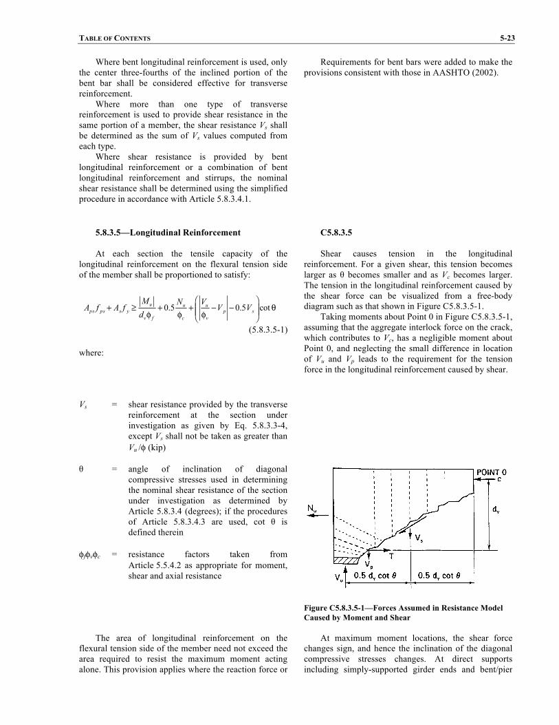
TABLE OF CONTENTS 5-23
Where bent longitudinal reinforcement is used, only the center three-fourths of the inclined portion of the bent bar shall be considered effective for transverse reinforcement.
Where more than one type of transverse reinforcement is used to provide shear resistance in the same portion of a member, the shear resistance Vs shall be determined as the sum of Vs values computed from each type.
Where shear resistance is provided by bent longitudinal reinforcement or a combination of bent longitudinal reinforcement and stirrups, the nominal shear resistance shall be determined using the simplified procedure in accordance with Article 5.8.3.4.1.
Requirements for bent bars were added to make the provisions consistent with those in AASHTO (2002).
5.8.3.5—Longitudinal Reinforcement At each section the tensile capacity of the
longitudinal reinforcement on the flexural tension side of the member shall be proportioned to satisfy:
(5.8.3.5-1)
where: Vs = shear resistance provided by the transverse
reinforcement at the section under investigation as given by Eq. 5.8.3.3-4, except Vs shall not be taken as greater than Vu /$ (kip)
C5.8.3.5 Shear causes tension in the longitudinal
reinforcement. For a given shear, this tension becomes larger as * becomes smaller and as Vc becomes larger. The tension in the longitudinal reinforcement caused by the shear force can be visualized from a free-body diagram such as that shown in Figure C5.8.3.5-1.
Taking moments about Point 0 in Figure C5.8.3.5-1, assuming that the aggregate interlock force on the crack, which contributes to Vc, has a negligible moment about Point 0, and neglecting the small difference in location of Vu and Vp leads to the requirement for the tension force in the longitudinal reinforcement caused by shear.
* = angle of inclination of diagonal compressive stresses used in determining the nominal shear resistance of the section under investigation as determined by Article 5.8.3.4 (degrees); if the procedures of Article 5.8.3.4.3 are used, cot * is defined therein
$f$v$c = resistance factors taken from
Article 5.5.4.2 as appropriate for moment, shear and axial resistance
Figure C5.8.3.5-1—Forces Assumed in Resistance Model Caused by Moment and Shear
The area of longitudinal reinforcement on the
flexural tension side of the member need not exceed the area required to resist the maximum moment acting alone. This provision applies where the reaction force or
At maximum moment locations, the shear force changes sign, and hence the inclination of the diagonal compressive stresses changes. At direct supports including simply-supported girder ends and bent/pier
5-24 AASHTO LRFD BRIDGE DESIGN SPECIFICATIONS
the load introduces direct compression into the flexural compression face of the member.
Eq. 5.8.3.5-1 shall be evaluated where simply-supported girders are made continuous for live loads. Where longitudinal reinforcement is discontinuous, Eq. 5.8.3.5-1 shall be re-evaluated.
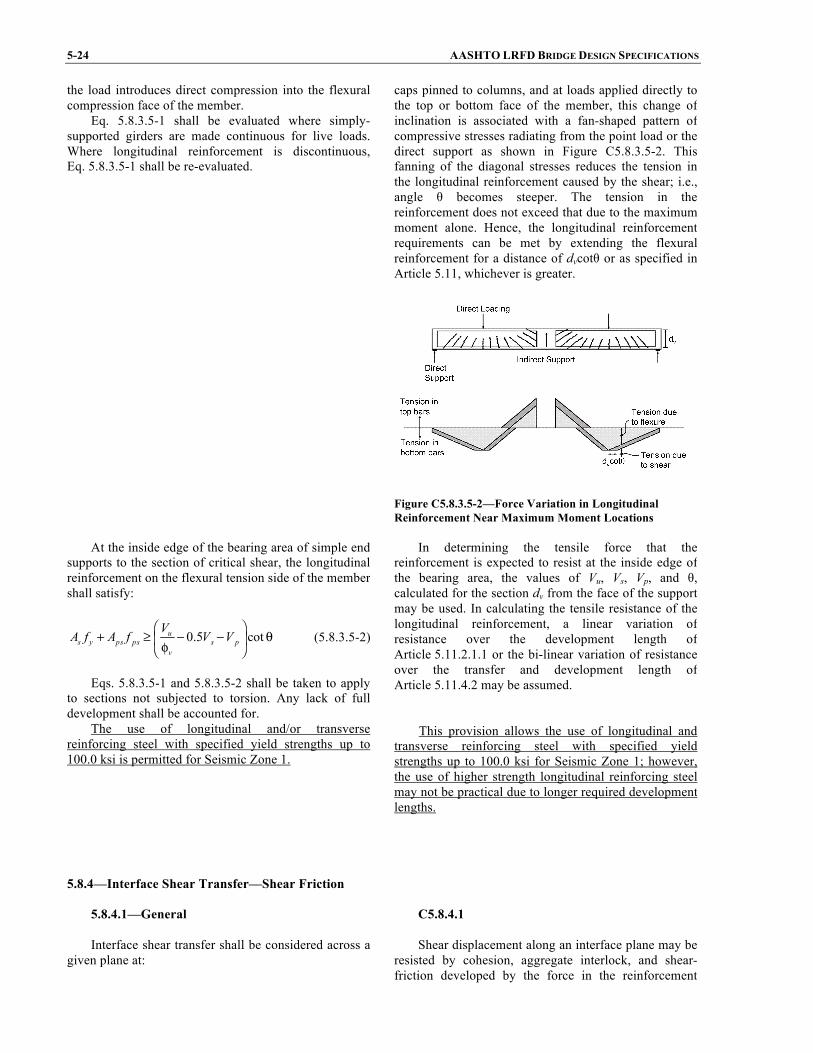
caps pinned to columns, and at loads applied directly to the top or bottom face of the member, this change of inclination is associated with a fan-shaped pattern of compressive stresses radiating from the point load or the direct support as shown in Figure C5.8.3.5-2. This fanning of the diagonal stresses reduces the tension in the longitudinal reinforcement caused by the shear; i.e., angle * becomes steeper. The tension in the reinforcement does not exceed that due to the maximum moment alone. Hence, the longitudinal reinforcement requirements can be met by extending the flexural reinforcement for a distance of dvcot* or as specified in Article 5.11, whichever is greater.
Figure C5.8.3.5-2—Force Variation in Longitudinal Reinforcement Near Maximum Moment Locations
At the inside edge of the bearing area of simple end
supports to the section of critical shear, the longitudinal reinforcement on the flexural tension side of the member shall satisfy:
(5.8.3.5-2)
Eqs. 5.8.3.5-1 and 5.8.3.5-2 shall be taken to apply
to sections not subjected to torsion. Any lack of full development shall be accounted for.
The use of longitudinal and/or transverse reinforcing steel with specified yield strengths up to 100.0 ksi is permitted for Seismic Zone 1.
In determining the tensile force that the reinforcement is expected to resist at the inside edge of the bearing area, the values of Vu, Vs, Vp, and *, calculated for the section dv from the face of the support may be used. In calculating the tensile resistance of the longitudinal reinforcement, a linear variation of resistance over the development length of Article 5.11.2.1.1 or the bi-linear variation of resistance over the transfer and development length of Article 5.11.4.2 may be assumed.
This provision allows the use of longitudinal and
transverse reinforcing steel with specified yield strengths up to 100.0 ksi for Seismic Zone 1; however, the use of higher strength longitudinal reinforcing steel may not be practical due to longer required development lengths.
5.8.4—Interface Shear Transfer—Shear Friction 5.8.4.1—General Interface shear transfer shall be considered across a
given plane at:
C5.8.4.1 Shear displacement along an interface plane may be
resisted by cohesion, aggregate interlock, and shear-friction developed by the force in the reinforcement
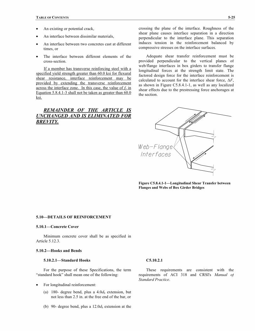
TABLE OF CONTENTS 5-25
• An existing or potential crack,
• An interface between dissimilar materials,
• An interface between two concretes cast at different times, or
crossing the plane of the interface. Roughness of the shear plane causes interface separation in a direction perpendicular to the interface plane. This separation induces tension in the reinforcement balanced by compressive stresses on the interface surfaces.
• The interface between different elements of the cross-section.
If a member has transverse reinforcing steel with a specified yield strength greater than 60.0 ksi for flexural shear resistance, interface reinforcement may be provided by extending the transverse reinforcement across the interface zone. In this case, the value of fy in Equation 5.8.4.1-3 shall not be taken as greater than 60.0 ksi.
Adequate shear transfer reinforcement must be provided perpendicular to the vertical planes of web/flange interfaces in box girders to transfer flange longitudinal forces at the strength limit state. The factored design force for the interface reinforcement is calculated to account for the interface shear force, #F, as shown in Figure C5.8.4.1-1, as well as any localized shear effects due to the prestressing force anchorages at the section.
REMAINDER OF THE ARTICLE IS UNCHANGED AND IS ELIMINATED FOR BREVITY.
Figure C5.8.4.1-1—Longitudinal Shear Transfer between Flanges and Webs of Box Girder Bridges
5.10—DETAILS OF REINFORCEMENT 5.10.1—Concrete Cover
Minimum concrete cover shall be as specified in
Article 5.12.3.
5.10.2—Hooks and Bends
5.10.2.1—Standard Hooks For the purpose of these Specifications, the term
“standard hook” shall mean one of the following:
• For longitudinal reinforcement:
(a) 180- degree bend, plus a 4.0db extension, but not less than 2.5 in. at the free end of the bar, or
(b) 90- degree bend, plus a 12.0db extension at the
C5.10.2.1 These requirements are consistent with the
requirements of ACI 318 and CRSI's Manual of Standard Practice.
5-26 AASHTO LRFD BRIDGE DESIGN SPECIFICATIONS
free end of the bar.
• For transverse reinforcement:
(a) No. 5 bar and smaller—90-degree bend, plus a 6.0db extension at the free end of the bar,
(b) No. 6, No. 7 and No. 8 bars—90-degree bend,
plus a 12.0db extension at the free end of the bar; and
(c) No. 8 bar and smaller—135-degree bend, plus a
6.0 db extension at the free end of the bar. where: db = nominal diameter of reinforcing bar (in.)
Standard hooks may be used with reinforcing steel having a specified yield strength up to 100.0 ksi.
Tests by Shahrooz et al. (2010) showed that
standard hooks are adequate for reinforcing steel with specified yield strengths up to 100.0 ksi if transverse, confining reinforcement is provided.
5.10.2.2—Seismic Hooks Seismic hooks shall consist of a 135-degree bend,
plus an extension of not less than the larger of 6.0db or 3.0 in. Seismic hooks shall be used for transverse reinforcement in regions of expected plastic hinges. Such hooks and their required locations shall be detailed in the contract documents.
For seismic hooks, fy shall not be taken greater than 75.0 ksi.
Detailing of seismic hooks has not been verified for
reinforcing steels with yield strengths exceeding 75.0 ksi.
5.10.6—Transverse Reinforcement for Compression Members
5.10.6.1—General The provisions of Article 5.10.11 shall also apply to
design and detailing in Seismic Zones 2, 3, and 4. Transverse reinforcement for compression members
may consist of either spirals or ties.
C5.10.6.1 Article 5.10.11.2 applies to Seismic Zone 1 but has
no additional requirements for transverse reinforcement for compression members.
In Seismic Zone 1, spirals and ties may be designed for specified yield strengths up to 100.0 ksi.
Spirals and ties with specified yield strengths of up to 100.0 ksi are permitted based on research by Shahrooz et al. (2010). Since this research did not consider seismic design, the use of high strength spirals and ties is limited to Seismic Zone 1.
TABLE OF CONTENTS 5-27
5.10.11.1—General The provisions of these Articles shall apply only to
the extreme event limit state. In addition to the other requirements specified in
Article 5.10, reinforcing steel shall also conform to the seismic resistance provisions specified herein.
Displacement requirements specified in Article 4.7.4.4 or longitudinal restrainers specified in Article 3.10.9.5 shall apply.
Bridges located in Seismic Zone 2 shall satisfy the requirements in Article 5.10.11.3. Bridges located in Seismic Zones 3 and 4 shall satisfy the requirements specified in Article 5.10.11.4.
The use of reinforcing steel with specified yield strengths of less than or equal to 100.0 ksi may be used in Seismic Zone 1, where permitted by specific articles.
C5.10.11.1 These Specifications are based on the work by the
Applied Technology Council in 1979–1980. The Loma Prieta earthquake of 1989 provided new insights into the behavior of concrete details under seismic loads. The California Department of Transportation initiated a number of research projects that have produced information that is useful for both the design of new structures and the retrofitting of existing structures. Much of this information has formed the basis of recent provisions published by NCHRP (2002, 2006), MCEER/ATC (2003), and FHWA (2006).
This new information relates to all facets of seismic engineering, including design spectra, analytical techniques, and design details. Bridge designers working in Seismic Zones 2, 3, and 4 are encouraged to avail themselves of current research reports and other literature to augment these Specifications.
The Loma Prieta earthquake confirmed the vulnerability of columns with inadequate core confinement and inadequate anchorage of longitudinal reinforcement. New areas of concern that emerged include:
• Lack of adequate reinforcement for positive
moments that may occur in the superstructure over monolithic supports when the structure is subjected to longitudinal dynamic loads;
• Lack of adequate strength in joints between columns and bent caps under transverse dynamic loads; and
• Inadequate reinforcement for torsion, particularly in outrigger-type bent caps.
The purpose of the additional design requirements of this Article is to increase the probability that the design of the components of a bridge are consistent with the overall design philosophy of ATC 6, especially for bridges located in Seismic Zones 2, 3, and 4, and that the potential for failures observed in past earthquakes is minimized. The additional column design requirements of this Article for bridges located in Seismic Zones 2, 3, and 4 are to ensure that a column is provided with reasonable ductility and is forced to yield in flexure and that the potential for a shear, compression, or loss of anchorage mode of failure is minimized. The additional design requirements for piers provide for some inelastic resistance; however, the R-factor specified for piers in Section 4 is to ensure that the anticipated inelastic resistance is significantly less than that of columns.
The actual ductility demand on a column or pier is a complex function of a number of variables, including:
• Earthquake characteristics,
5-28 AASHTO LRFD BRIDGE DESIGN SPECIFICATIONS
• Design force level,
• Periods of vibration of the bridge,
• Shape of the inelastic hysteresis loop of the columns,
• Elastic damping coefficient,
• Contributions of foundation and soil conditions to structural flexibility, and
• Plastic hinge length of the column.
The damage potential of a column is also related to the ratio of the duration of strong motion shaking to the natural period of vibration of the bridge. This ratio will be an indicator of the number of yield excursions and hence of the cumulative ductility demand.
5.10.11.4.1d—Transverse Reinforcement for Confinement at Plastic Hinges
The cores of columns and pile bents shall be
confined by transverse reinforcement in the expected plastic hinge regions. The transverse reinforcement for confinement shall have a yield strength not more than that of the longitudinal reinforcement, and the spacing shall be taken as specified in Article 5.10.11.4.1e.
For a circular column, the volumetric ratio of spiral or seismic hoop reinforcement, ,s, shall satisfy either that required in Article 5.7.4.6 or:
(5.10.11.4.1d-1)
where: f "c = specified compressive strength of concrete at
28 days, unless another age is specified (ksi) fy = yield strength of reinforcing bars (ksi) < 75.0
ksi
C5.10.11.4.1d Plastic hinge regions are generally located at the top
and bottom of columns and pile bents. The largest of either these requirements or those of Article 5.10.11.4.1c should govern; these requirements are not in addition to those of Article 5.10.11.4.1c.
The main function of the transverse reinforcement specified in this Article is to ensure that the axial load carried by the column after spalling of the concrete cover will at least equal the load carried before spalling and to ensure that buckling of the longitudinal reinforcement is prevented. Thus, the spacing of the confining reinforcement is also important.
Within plastic hinge zones, splices in spiral
reinforcement shall be made by full-welded splices or by full-mechanical connections.
Careful detailing of the confining steel in the plastic hinge zone is required because of spalling and loss of concrete cover. With deformation associated with plastic hinging, the strains in the transverse reinforcement increase. Ultimate-level splices are required. Similarly, rectangular hoops should be anchored by bending ends back into the core.
For a rectangular column, the total gross sectional area, Ash, of rectangular hoop reinforcement shall satisfy either:
(5.10.11.4.1d-2)
Figures C5.10.11.4.1d-2 and C5.10.11.4.1d-4 illustrate the use of Eqs. 5.10.11.4.1d-2 and 5.10.11.4.1d-3. The required total area of hoop reinforcement should be determined for both principal axes of a rectangular or oblong column. Figure C5.10.11.4.1d-4 shows the distance to be utilized for hc and the direction of the corresponding reinforcement for both principal directions of a rectangular
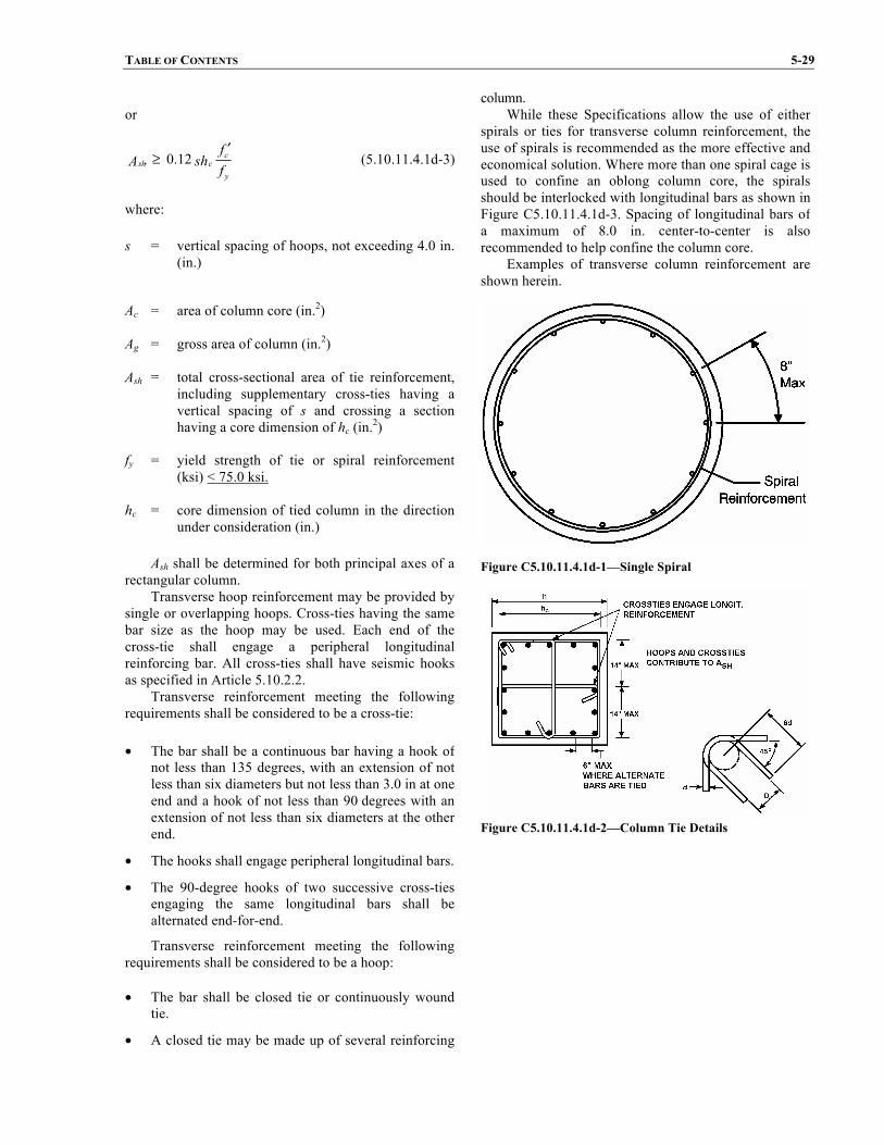
TABLE OF CONTENTS 5-29
or
(5.10.11.4.1d-3)
where:
s = vertical spacing of hoops, not exceeding 4.0 in.
(in.)
column. While these Specifications allow the use of either
spirals or ties for transverse column reinforcement, the use of spirals is recommended as the more effective and economical solution. Where more than one spiral cage is used to confine an oblong column core, the spirals should be interlocked with longitudinal bars as shown in Figure C5.10.11.4.1d-3. Spacing of longitudinal bars of a maximum of 8.0 in. center-to-center is also recommended to help confine the column core.
Examples of transverse column reinforcement are shown herein.
Ac = area of column core (in.2) Ag = gross area of column (in.2) Ash = total cross-sectional area of tie reinforcement,
including supplementary cross-ties having a vertical spacing of s and crossing a section having a core dimension of hc (in.2)
fy = yield strength of tie or spiral reinforcement
(ksi) < 75.0 ksi. hc = core dimension of tied column in the direction
under consideration (in.) Ash shall be determined for both principal axes of a
rectangular column. Transverse hoop reinforcement may be provided by
single or overlapping hoops. Cross-ties having the same bar size as the hoop may be used. Each end of the cross-tie shall engage a peripheral longitudinal reinforcing bar. All cross-ties shall have seismic hooks as specified in Article 5.10.2.2.
Transverse reinforcement meeting the following requirements shall be considered to be a cross-tie:
• The bar shall be a continuous bar having a hook of
not less than 135 degrees, with an extension of not less than six diameters but not less than 3.0 in at one end and a hook of not less than 90 degrees with an extension of not less than six diameters at the other end.
• The hooks shall engage peripheral longitudinal bars.
• The 90-degree hooks of two successive cross-ties engaging the same longitudinal bars shall be alternated end-for-end.
Transverse reinforcement meeting the following requirements shall be considered to be a hoop:
• The bar shall be closed tie or continuously wound
tie.
• A closed tie may be made up of several reinforcing
Figure C5.10.11.4.1d-1—Single Spiral
Figure C5.10.11.4.1d-2—Column Tie Details
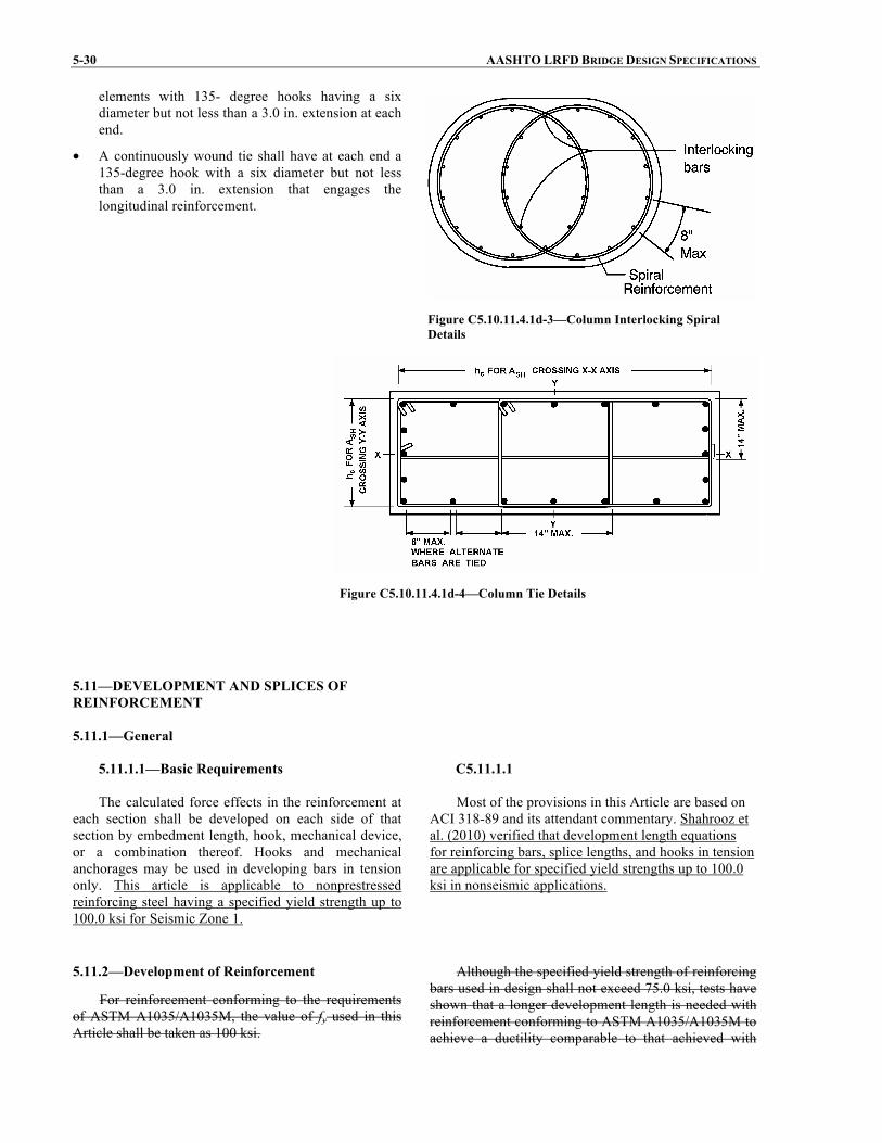
5-30 AASHTO LRFD BRIDGE DESIGN SPECIFICATIONS
elements with 135- degree hooks having a six diameter but not less than a 3.0 in. extension at each end.
• A continuously wound tie shall have at each end a 135-degree hook with a six diameter but not less than a 3.0 in. extension that engages the longitudinal reinforcement.
Figure C5.10.11.4.1d-3—Column Interlocking Spiral Details
Figure C5.10.11.4.1d-4—Column Tie Details
5.11—DEVELOPMENT AND SPLICES OF REINFORCEMENT
5.11.1—General
5.11.1.1—Basic Requirements The calculated force effects in the reinforcement at
each section shall be developed on each side of that section by embedment length, hook, mechanical device, or a combination thereof. Hooks and mechanical anchorages may be used in developing bars in tension only. This article is applicable to nonprestressed reinforcing steel having a specified yield strength up to 100.0 ksi for Seismic Zone 1.
C5.11.1.1 Most of the provisions in this Article are based on
ACI 318-89 and its attendant commentary. Shahrooz et al. (2010) verified that development length equations for reinforcing bars, splice lengths, and hooks in tension are applicable for specified yield strengths up to 100.0 ksi in nonseismic applications.
5.11.2—Development of Reinforcement
For reinforcement conforming to the requirements
of ASTM A1035/A1035M, the value of fy used in this Article shall be taken as 100 ksi.
Although the specified yield strength of reinforcing bars used in design shall not exceed 75.0 ksi, tests have shown that a longer development length is needed with reinforcement conforming to ASTM A1035/A1035M to achieve a ductility comparable to that achieved with
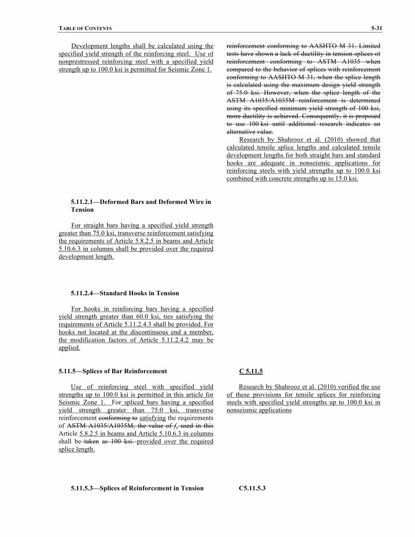
TABLE OF CONTENTS 5-31
Development lengths shall be calculated using the specified yield strength of the reinforcing steel. Use of nonprestressed reinforcing steel with a specified yield strength up to 100.0 ksi is permitted for Seismic Zone 1.
reinforcement conforming to AASHTO M 31. Limited tests have shown a lack of ductility in tension splices of reinforcement conforming to ASTM A1035 when compared to the behavior of splices with reinforcement conforming to AASHTO M 31, when the splice length is calculated using the maximum design yield strength of 75.0 ksi. However, when the splice length of the ASTM A1035/A1035M reinforcement is determined using its specified minimum yield strength of 100 ksi, more ductility is achieved. Consequently, it is proposed to use 100 ksi until additional research indicates an alternative value.
Research by Shahrooz et al. (2010) showed that calculated tensile splice lengths and calculated tensile development lengths for both straight bars and standard hooks are adequate in nonseismic applications for reinforcing steels with yield strengths up to 100.0 ksi combined with concrete strengths up to 15.0 ksi.
5.11.2.1—Deformed Bars and Deformed Wire in Tension For straight bars having a specified yield strength
greater than 75.0 ksi, transverse reinforcement satisfying the requirements of Article 5.8.2.5 in beams and Article 5.10.6.3 in columns shall be provided over the required development length.
5.11.2.4—Standard Hooks in Tension For hooks in reinforcing bars having a specified
yield strength greater than 60.0 ksi, ties satisfying the requirements of Article 5.11.2.4.3 shall be provided. For hooks not located at the discontinuous end a member, the modification factors of Article 5.11.2.4.2 may be applied.
5.11.5—Splices of Bar Reinforcement Use of reinforcing steel with specified yield
strengths up to 100.0 ksi is permitted in this article for Seismic Zone 1. For spliced bars having a specified yield strength greater than 75.0 ksi, transverse reinforcement conforming to satisfying the requirements of ASTM A1035/A1035M, the value of fy used in this Article 5.8.2.5 in beams and Article 5.10.6.3 in columns shall be taken as 100 ksi. provided over the required splice length.
C 5.11.5 Research by Shahrooz et al. (2010) verified the use
of these provisions for tensile splices for reinforcing steels with specified yield strengths up to 100.0 ksi in nonseismic applications
5.11.5.3—Splices of Reinforcement in Tension C5.11.5.3
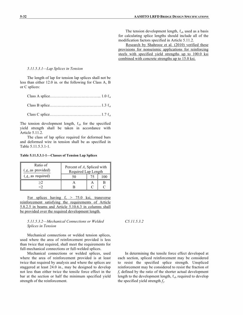
5-32 AASHTO LRFD BRIDGE DESIGN SPECIFICATIONS
The tension development length, (d, used as a basis
for calculating splice lengths should include all of the modification factors specified in Article 5.11.2.
Research by Shahrooz et al. (2010) verified these provisions for nonseismic applications for reinforcing steels with specified yield strengths up to 100.0 ksi combined with concrete strengths up to 15.0 ksi.
5.11.5.3.1—Lap Splices in Tension
The length of lap for tension lap splices shall not be less than either 12.0 in. or the following for Class A, B or C splices:
Class A splice………………………………... 1.0 (d Class B splice………………………………… 1.3 (d Class C splice………………………………… 1.7 (d
The tension development length, (d, for the specified yield strength shall be taken in accordance with Article 5.11.2.
The class of lap splice required for deformed bars and deformed wire in tension shall be as specified in Table 5.11.5.3.1-1.
Table 5.11.5.3.1-1—Classes of Tension Lap Splices
Percent of As Spliced with Required Lap Length
Ratio of
50 75 100
'2 <2
A B
A C
B C
For splices having fy > 75.0 ksi, transverse
reinforcement satisfying the requirements of Article 5.8.2.5 in beams and Article 5.10.6.3 in columns shall be provided over the required development length.
5.11.5.3.2—Mechanical Connections or Welded Splices in Tension Mechanical connections or welded tension splices,
used where the area of reinforcement provided is less than twice that required, shall meet the requirements for full-mechanical connections or full-welded splices.
C5.11.5.3.2
Mechanical connections or welded splices, used where the area of reinforcement provided is at least twice that required by analysis and where the splices are staggered at least 24.0 in., may be designed to develop not less than either twice the tensile force effect in the bar at the section or half the minimum specified yield strength of the reinforcement.
In determining the tensile force effect developed at each section, spliced reinforcement may be considered to resist the specified splice strength. Unspliced reinforcement may be considered to resist the fraction of fy defined by the ratio of the shorter actual development length to the development length, (d, required to develop the specified yield strength fy.
TABLE OF CONTENTS 5-33
5.15—REFERENCES
AASHTO. 1989. Guide Specifications for Design and Construction of Segmental Concrete Bridges, First Edition, GSCB-1. American Association of State Highway and Transportation Officials, Washington, DC. AASHTO. 1999. Guide Specification for Design and Construction of Segmental Concrete Bridges, Second Edition, GSCB-2. American Association of State Highway and Transportation Officials, Washington, DC. AASHTO. 2002. Standard Specifications for Highway Bridges, 17th Edition, HB-17. American Association of State Highway and Transportation Officials, Washington, DC. AASHTO. 2009. Standard Specifications for Transportation Materials and Methods of Sampling and Testing, 29th Edition, HM-29. American Association of State Highway and Transportation Officials, Washington, DC. Abdalla, O. A., J. A. Ramirez, and R. H.Lee. 1993. Strand Debonding in Pretensioned Beams—Precast Prestressed Concrete Bridge Girders with Debonded Strands—Continuity Issues, FHWA/INDOT/JHRP-92-94. Joint Highway Research Project, Indiana Department of Transportation/Purdue University, West Lafayette, IN, June 1993. ACI. 1989. Building Code Requirements for Reinforced Concrete and Commentary. American Concrete Institute 318R-89. American Concrete Institute, Detroit, MI. ACI. 1994. Detailing Manual. Publication SP-66. American Concrete Institute, Detroit, MI. ACI. 1999. Building Code Requirements for Structural Concrete. 318-99 and Commentary. 318R-99. American Concrete Institute, Farmington Hills, MI. ACI. 2002. Building Code 318-02. American Concrete Institute, Farmington Hills, MI. ACI Committee 201. 1992. Durability of Concrete. ACI SP-131. American Concrete Institute, Farmington Hills, MI. ACI Committee 207. 1973. Manual of Concrete Practice. ACI 207.2R73, American Concrete Institute, Farmington Hills, MI. ACI Committee 209. 1982. Prediction of Creep, Shrinkage and Temperature Effects in Concrete Structures. ACI 209R-82. American Concrete Institute, Farmington Hills, MI. ACI Committee 215. 1992. Considerations for Design of Concrete Structures Subjected to Fatigue Loading. ACI 215R-92. American Concrete Institute, Farmington Hills, MI. Reapproved in 1997. ACI Committee 222. 1987. Corrosion of Metals in Concrete. ACI 222R-85. American Concrete Institute, Detroit, MI. ACI Committee 350. 1989. Environmental Engineering Concrete Structures. ACI 350R-89. American Concrete Institute, Farmington Hills, MI, p. 24. ACI Committee 363. 1992. State-of-the-Art Report on High-Strength Concrete. ACI 363R-92. American Concrete Institute, Farmington Hills, MI. ACI Committee 439. 1991. Mechanical Connections of Reinforcing Bars. ACI 439.3R. Vol. 88, No. 2, American Concrete Institute, Farmington Hills, MI, pp. 222–239. Al-Omaishi, N. 2001. Prestress Losses in High Strength Pretensioned Concrete Bridge Girders. Ph.D. dissertation, University of Nebraska-Lincoln, December 2001. Amorn, W., J. Bowers, A. Girgis, and M. K. Tadros. “Fatigue of Deformed Welded-Wire Reinforcement,” PCI Journal. Prestressed Concrete Institute, Chicago, IL, Vol. 52, No. 1, pp. 106–120.
5-34 AASHTO LRFD BRIDGE DESIGN SPECIFICATIONS
Anderson, A. R. 1973. “Stretched-Out AASHTO-PCI Beams Types III and IV for Longer Span Highway Bridges,” PCI Journal. Prestressed Concrete Institute, Chicago, IL, Vol. 18, No. 5, September–October 1973. ASCE. 1999. “A Direct Solution for Elastic Prestress Loss in Pretensioned Concrete Girders,” Practice Periodical on Structural Design and Construction. American Society of Civil Engineers, Reston, VA, November 1999. Bae, S., and O. Bayrak, 2003. “Stress Block Parameters for High Strength Concrete Members,” ACI Structural Journal. American Concrete Institute, Farmington Hills, MI, Vol. 100, No. 5, September–October 2003, pp. 626–636. Bakhoum, M. M., O. Buyukozturk, and S. M. Beattie. 1989. “Structural Performance of Joints on Precast Concrete Segmental Bridges.” MIT Research Report No. R89-26. Massachusetts Institute of Technology, Cambridge, MA, November 1989. Baran, E., A. E. Schultz, and C. E. French. 2005. “Analysis of the Flexural Strength of Prestressed Concrete Flanged Sections,” PCI Journal. Prestressed Concrete Institute, Chicago, IL, Vol. 50, No. 1, January–February 2005, pp. 74–93. Base, G. D., J. B. Reed, A. W. Beeby, and H. P. J. Taylor. 1966. An Investigation of the Crack Control Characteristics of Various Types of Bar in Reinforced Concrete Beams, Research Report No. 18. Cement and Concrete Association, London, England, December 1966, p. 44. Bayrak, O. 1999. “Seismic Performance of Rectilinearly Confined High-Strength Concrete Columns.” Ph.D. dissertation, University of Toronto, Ontario, Canada, pp. 80–187. Bazant, Z. P., and F. H. Wittman, eds. 1982. Creep and Shrinkage in Concrete Structures. John Wiley and Sons, Inc., New York, NY. Beaupre, R. J., L. C. Powell, J. E. Breen, and M. E. Kreger. 1988. “Deviation Saddle Behavior and Design for Externally Post-Tensioned Bridges,” Research Report 365-2. Center for Transportation Research, July 1988. Beeby, A. W. 1983. “Cracking, Cover and Corrosion of Reinforcement,” Concrete International: Design and Construction. American Concrete Institute, Farmington Hills, MI, Vol. 5, No. 2, February 1983, pp. 34–40. Bentz, E. C. and M. P. Collins. 2006. “Development of the 2004 CSA A23.3 Shear Provisions for Reinforced Concrete,” Canadian Journal of Civil Engineering. NRC Research Press, Ottawa, ON, Canada, Vol. 33, No. 5, May 2006, pp. 521–534. Bentz, E. C., F. J. Vecchio, and M. P. Collins. 2006. “The Simplified MCFT for Calculating the Shear Strength of Reinforced Concrete Elements,” ACI Structural Journal. American Concrete Institute, Farmington Hills, MI, Vol. 103, No. 4, July–August 2006, pp. 614–624. Breen, J. E., O. Burdet, C. Roberts, D. Sanders, and G. Wollmann. 1994. Anchorage Zone Reinforcement for Post-Tensioned Concrete Girders, NCHRP Report 356. Transportation Research Board, National Research Council, Washington, DC. Breen, J. E., and S. Kashima. 1991. “Verification of Load Distribution and Strength of Segmental Post-Tensioned Concrete Bridges,” Engineering Structures. Vol. 13, No. 2. Bruce, R. N., H. G. Russell, and J. J. Roller. 2003. Fatigue and Shear Behavior of HPC Bulb-Tee Girders, FHWA/LA 03/382. Louisiana Transportation Research Center, Baton Rouge, LA. Interim report. Bryant, Anthony A., and Chavatit Vadhanavikkit. 1987. “Creep Shrinkage-Size, and Age at Loading Effects,” ACI Material Journal. American Concrete Institute, Farmington Hills, MI, March–April 1987. Burdet, O. L. 1990. “Analysis and Design of Anchorage Zones in Post-Tensioned Concrete Bridges.” Ph.D. diss. University of Texas, Austin, TX, May 1990.
TABLE OF CONTENTS 5-35
Castrodale, R. W., and C. D. White. 2004. “Extending Span Ranges of Precast, Prestressed Concrete Girders,” NCHRP Report 517. Transportation Research Board, National Research Council, Washington, DC.
CEB. 1990. CEB-FIP Model Code for Concrete Structures. Comite Euro-International de Beton. Available from Lewis Brooks, 2 Blagdon Road, New Malden, Surrey, KT3 4AD, England.
Collins, M. P., and D. Mitchell. 1991. Prestressed Concrete Structures. Prentice Hall: Englewood Cliffs, NJ.
Collins, M. P, D. Mitchell, P. E. Adebar, and F. J. Vecchio. 1996. “A General Shear Design Method,” ACI Structural Journal. American Concrete Institute, Farmington Hills, MI, Vol. 93, No. 1, pp. 36–45.
CRSI. Manual of Standard Practice. Concrete Reinforcing Steel Institute, Schaumburg, IL, 60195.
CSA. 2004. Design of Concrete Structures, CSA A23.3-04. Canadian Standards Association, Mississaugua, ON, Canada.
DeCassio, R. D., and C. P. Siess. 1960. “Behavior and Strength in Shear of Beams and Frames without Web Reinforcement,” ACI Proceedings. American Concrete Institute, Farmington Hills, MI, Vol. 56, February 1960. DeJong, S. J. and C. MacDougall, 2006. “Fatigue Behaviour of MMFX Corrosion-Resistant Reinforcing Steel,” Proceedings of the 7th International Conference on Short and Medium Span Bridges, Montreal, Canada 2006.
Destefano, R. J., J. Evans, M. K. Tadros, and C. Sun. 2003. “Flexural Crack Control in Concrete Bridge Structures.” PCI Convention, October 19, 2003. FHWA. 1998. A New Development Length Equation for Pretensioned Strands in Bridge Beams and Piles, FHWA-RD-98-116. Federal Highway Administration, U.S. Department of Transportation, Washington, DC, December 1998.
FHWA. 2006. Seismic Retrofitting Manual for Highway Structures, Part 1—Bridges, FHWA-HRT-06-032. Federal Highway Administration, U.S. Department of Transportation, Washington DC.
Frantz G. C., and J. E. Breen. 1980. “Design Proposal for Side Face Crack Control Reinforcement for Large Reinforced Concrete Beams.” Concrete International: Design and Construction, Vol. 2, No. 10, October 1980, pp. 29–34.
Frosch, R. J. 2001. “Flexural Crack Control in Reinforced Concrete,” Design and Construction Practices to Mitigate Cracking, SP-204. American Concrete Institute, Farmington Hills, MI, pp. 135–154.
Fung, G., R. F. LeBeau, E. D., Klein, J. Belvedere, and A. G. Goldschmidt. 1971. Field Investigation of Bridge Damage in the San Fernando Earthquake. Bridge Department, Division of Highways, California Department of Transportation, Sacramento, CA.
Gergely, P., and L. A. Lutz. 1968. “Maximum Crack Width in Reinforced Concrete Flexural Members.” In Causes, Mechanism, and Control of Cracking in Concrete, SP-20. American Concrete Institute, Detroit, MI, pp. 87–117.
Ghali, A., and R. Favre. 1968. Concrete Structures, Stresses, and Deformations. Chapman Hall: London, England, Appendix A.
Girgis, A., C. Sun, and M. K. Tadros. 2002. “Flexural Strength of Continuous Bridge Girders—Avoiding the Penalty in the AASHTO LRFD Specifications,” Open Forum: Problems and Solutions, PCI Journal. Prestressed Concrete Institute, Chicago, IL, Vol. 47, No. 4, July–August 2002, pp. 138–141.
Griezic, A., W. D. Cook, and D. Mitchell. 1994. ‘Tests to Determine Performance of Deformed Welded Wire Fabric Stirrups,” ACI Structural Journal. American Concrete Institute, Farmington Hills, MI, Vol. 91, No. 2, March–April 1994, pp. 211–220.
Guyon, Y. 1953. Prestressed Concrete. John Wiley and Sons, Inc., New York, NY.
Halvorsen, G. T. 1987. “Code Requirements for Crack Control.” In Proc. of the Lewis H. Tuthill International Symposium on Concrete and Concrete Construction. SP104-15. 84-AB. American Concrete Institute, Farmington Hills, MI.
5-36 AASHTO LRFD BRIDGE DESIGN SPECIFICATIONS
Hamad, B. S., J. O. Jirsa, and N. I. D'Abreu. 1990. Effect of Epoxy Coating on Bond and Anchorage of Reinforcement in Concrete Structures, Research Project 1181-1F. Center for Transportation Research, University of Texas, Austin, TX, December 1990, p. 242. Hawkins, N. M., and D. A. Kuchma. 2006. Simplified Shear Design of Structural Concrete Members, NCHRP Report 549. Transportation Research Board, National Research Council, Washington, DC. Available online at http://onlinepubs.trb.org/onlinepubs/nchrp/nchrp_w78.pdf. Hawkins, N. M., and D. A. Kuchma. 2007. Application of LRFD Bridge Design Specifications to High- Strength Structural Concrete: Shear Provisions, NCHRP Report 579, Transportation Research Board, National Research Council, Washington, DC. Available online at http://onlinepubs.trb.org/onlinepubs/nchrp/nchrp_rpt_579.pdf. Hawkins, N. M., D. A. Kuchma, R. F. Mast, M. L. Marsh, and K. H. Reineck. 2005. Simplified Shear Design of Structural Concrete Members, NCHRP Report XX1. Transportation Research Board, National Research Council, Washington, DC. Hawkins, N. M., D. A. Kuchma, H. G. Russell, G. J. Klein, and N. S. Anderson. 2006. Application of the LRFD Bridge Design Specifications to High-Strength Structural Concrete: Shear Provisions, NCHRP Report XX2. Transportation Research Board, National Research Council, Washington, DC. Highway Engineering Division. 1991. Ontario Highway Bridge Design Code. Highway Engineering Division, Ministry of Transportation and Communications, Toronto, ON. Hofbeck, J. A., I. O. Ibrahim, and A. H. Mattock. 1969. “Shear Transfer in Reinforced Concrete,” ACI Journal. American Concrete Institute, Farmington Hills, MI, Vol. 66, No. 2, February 1969, pp. 119–128. Hognestad, E. 1991. “Design Considerations for Service Life,” Concrete International: Design and Construction. American Concrete Institute, Farmington Hills, MI, Vol. 13, No. 3, March 1991, pp. 57–60. Huo, X. S., N. Al-Omaishi, and M. K. Tadros. 2001. “Creep, Shrinkage, and Modulus of Elasticity of High Performance Concrete,” ACI Materials Journal. American Concrete Institute, Farmington Hills, MI, Vol. 98, No. 6, November–December 2001, pp. 440–449. Ibrahim, H. H. H., and J. G. MacGregor. 1996. “Tests of Eccentrically Loaded High-Strength Concrete Columns,” ACI Structural Journal. American Concrete Institute, Farmington Hills, MI, Vol. 93, No. 5, September–October 1996, pp. 585–594. Jirsa, J. O. 1979. “Applicability to Bridges of Experimental Seismic Test Results Performed on Subassemblages of Buildings.” In Proc. of a Workshop on the Earthquake Resistance of Highway Bridges. Applied Technology Council, Berkeley, CA, January 1979. Jongpitaksseel, N., J. Bowers, W. Amornrattanepong, and M. K. Tadros. 2004. Development of Fatigue Limit Formula for Deformed Welded Wire Reinforcement (WWR), 2004 Concrete Bridge Conference Paper #79. National Concrete Bridge Council, Charlotte, NC. Kaar, P. H. 1966. “High-Strength Bars as Concrete Reinforcement, Part 8: Similitude in Flexural Cracking of T-Beam Flanges,” Journal PCA Research and Development Laboratories. Portland Cement Association, Skokie, IL, Vol. 8, No. 2, May 1966, pp. 2–12. Reprinted as Development Department Bulletin D106. Kaar, P. H., L. B. Kriz, and E. Hognestad. 1961. “Precast-Prestressed Concrete Bridges, 6. Test of Half-Scale Highway Bridge Continuous over Two Spans,” Journal of the PCA Research and Development Laboratories. Vol. 3, No. 3, Sept. 1961, pp. 30–70. Also reprinted as PCA Bulletin, D51. Ketchum, M. A. 1986. Redistribution of Stresses in Segmentally Erected Prestressed Concrete Bridges, Report No. UCB/SESM-86/07. Department of Civil Engineering, University of California, Berkeley, CA, May 1986.
TABLE OF CONTENTS 5-37
Khan, A. A., W. D. Cook, and D. Mitchell. 1996. “Tensile Strength of Low, Medium, and High-Strength Concretes at Early Ages,” ACI Materials Journal. American Concrete Institute, Farmington Hills, MI, Vol. 93, No. 5, September–October 1996, pp. 487–493. Kordina, K., and V. Weber. 1984. “Einfluss der Ausbildung unbewehrter Pressfugen auf die Tragfahigkeit von schrager Druckstreben in den Stegen von Segmentbauteilen.” In Deutscher Ausschuss fur Stahlbeton. Heft 350, Berlin, Germany. Koseki, K., and J. E. Breen. 1983. Exploratory Study of Shear Strength of Joints for Precast Segmental Bridges, Research Report 258-1. Center for Transportation Research, University of Texas, Austin, TX, September 1983.
Lehman, D. et al. 2001. “Repair of Severely Damaged Bridge Columns,” ACI Structural Journal. American Concrete Institute, Farmington Hills, MI, Vol. 98, No. 2, March 2001, pp. 233–242.
Leonhardt, F. 1964. Prestressed Concrete, Design, and Construction. Wilhelm Ernest and Sohn: Berlin.
Leonhardt, F. 1987. “Cracks and Crack Control in Concrete Structures.” In IABSE Proceedings. P109/87, International Association for Bridge and Structural Engineers, Zurich, Switzerland, pp. 25–44. Loov, R. E. 1988. “A General Equation for the Steel Stress for Bonded Prestressed Tendons,” PCI Journal. Prestressed Concrete Institute, Chicago, IL, Vol. 33, No. 6, November–December 1988, pp. 108–137.
Loov, R. E., and A. K. Patnaik. 1994. “Horizontal Shear Strength of Composite Concrete Beams with a Rough Interface.” PCI Journal, Vol. 39, No. 1, Prestressed Concrete Institute, Chicago, IL, January–February 1994, pp. 48–69. See also “Reader Comments,” PCI Journal. Prestressed Concrete Institute, Chicago, IL, Vol. 39, No. 5, September–October 1994, pp. 106–109.
Lwin, M., and B. Khaleghi. 1997. “Time-Dependent Prestress Losses in Prestressed Concrete Girders Built of High-Performance Concrete,” Transportation Research Record. Transportation Research Board, National Research Council, Washington, DC, No. 1594.
Ma, Z., X. Huo, M. K. Tadros, and M. Baishya. 1998. “Restraint Moments in Precast/Prestressed Concrete Continuous Bridges,” PCI Journal. Prestressed Concrete Institute, Chicago, IL, Vol. 43, No. 6, November–December 1998, pp. 40–56.
Ma, Z., M. K. Tadros, and M. Baishya. 2000. “Shear Behavior of Pretensioned High-Strength Concrete Bridge I-Girders,” ACI Structural Journal. American Concrete Institute, Farmington Hills, MI, Vol. 97, No. 1, January–February 2000, pp. 185–192. MacGregor, R. J. G. 1989. “Evaluation of Strength and Ductility of the Three-Span Externally Post-Tensioned Box Girder Bridge Model.” Ph.D. diss. University of Texas, Austin, TX, August 1989.
MacGregor, R. J. G., M. E. Kreger, and J. E. Breen. 1989. Strength and Ductility of a Three-Span Externally Post-Tensioned Bridge Model, Research Report 365-3F. Center for Transportation Research, University of Texas, Austin, TX, January 1989.
Mast, R. F. 1992. “Unified Design Provisions for Reinforced and Prestressed Concrete Flexural and Compression Members,” ACI Structural Journal. American Concrete Institute, Farmington Hills, MI, Vol. 89, No. 2, March–April 1992, pp. 185–199. See also discussions by R. K. Devalapura and M. K. Tadros, C. W. Dolan and J. V. Loscheider and closure to discussions in Vol. 89, No. 5, September–October 1992, pp. 591–593.
Mattock, A. H. 1961. “Precast-prestressed Concrete Bridges, 5. Creep and Shrinkage Studies,” Journal of the PCA Research and Development Laboratories. Portland Cement Association, Skokie, IL, Vol. 3, No. 2, May 1961, pp. 32–66. Also reprinted as PCA Bulletin, D46.
Mattock, A. H. 1974. “Shear Transfer in Concrete Having Reinforcement at an Angle to the Shear Plane.” In Vol. 1, Shear in Reinforced Concrete. SP-42. American Concrete Institute, Farmington Hills, MI, pp.17–42.
Mattock, A. H. 1987. “Anchorage of Stirrups in a Thin Cast-in-Place Topping,” PCI Journal, Prestressed Concrete Institute, Chicago, IL, Vol. 32, No. 6, November–December 1987, pp. 70–85.
5-38 AASHTO LRFD BRIDGE DESIGN SPECIFICATIONS
Mattock, A. H., L. B. Kriz, and E. Hognestad. 1961. “Rectangular Concrete Stress Distribution in Ultimate Strength Design,” ACI Journal. American Concrete Institute, Farmington Hills, MI, Vol. 32, No. 8, February 1961, pp. 875–928.
MCEER/ATC. 2003. Recommended LRFD Guidelines for the Seismic Design of Highway Bridges, Special Publication No. MCEER-03-SP03. Multidisciplinary Center for Earthquake Engineering Research, Buffalo, NY. Miller, R. A., R. Castrodale, A. Mirmiran, and M. Hastak. 2004. Connection of Simple-Span Precast Concrete Girders for Continuity, NCHRP Report 519. Transportation Research Board, National Research Council, Washington, DC.
Mirmiran, A., S. Kulkarni, R. Castrodale, R. Miller, and M. Hastak. 2001. “Nonlinear Continuity Analysis of Precast, Prestressed Concrete Girders with Cast-in-Place Decks and Diaphragms,” PCI Journal. Prestressed Concrete Institute, Chicago, IL, Vol. 46, No. 5, September–October 2001, pp. 60–80. Naaman, A. E. 1982. Prestressed Concrete Analysis and Design: Fundamentals. McGraw Hill, New York, NY, p. 670. Naaman, A. E. 1985. “Partially Prestressed Concrete: Review and Recommendations,” PCI Journal. Prestressed Concrete Institute, Chicago, IL, Vol. 30, No. 6, November–December 1985, pp. 30–71. Naaman, A. E. 1987. “Proposed Revisions to ACI Building Code and Commentary. ACI 318-83.” Proposal to ACI Committee 423, Prestressed Concrete Institute, Chicago, IL. First draft March 1987. Naaman, A. E. 1988. “Partially Prestressed Concrete: Design Methods and Proposed Code Recommendations.” In Proc., International Conference on Partially Prestressed Concrete Structures. T. Javor, ed. Bratislava, Chechoslovakia, June 1988. Naaman, A. E. 1989. “Discussion of Loov 1988,” PCI Journal. Prestressed Concrete Institute, Chicago, IL, Vol. 34, No. 6, November–December 1989, pp. 144–147. Naaman, A. E. 1990. “A New Methodology for the Analysis of Beams Prestressed with Unbonded Tendons.” In External Prestressing in Bridges, ACI SP-120. A.E. Naaman and J. Breen, eds. American Concrete Institute, Farmington Hills, MI, pp. 339–354. Naaman, A. E. 1992. “Unified Design Recommendations for Reinforced Prestressed and Partially Prestressed Concrete Bending and Compression Members,” ACI Structural Journal. American Concrete Institute, Farmington Hills, MI, Vol. 89, No. 2, March–April 1992, pp. 200–210. Naaman, A. E. 2002. “Rectangular Stress Block and T-Section Behavior,” Open Forum: Problems and Solutions, PCI Journal. Prestressed Concrete Institute, Chicago, IL, Vol. 47, No. 5, September–October 2002, pp. 106–112. Naaman, A. E., et al. 1990. “Discussion of Skogman et al. 1988,” PCI Journal. Prestressed Concrete Institute, Chicago, IL, Vol. 35, No. 2, March–April 1990, pp. 82–89. Naaman, A. E., and F. M. Alkhairi. 1991. “Stress at Ultimate in Unbonded Prestressing Tendons—Part I: Evaluation of the State-of-the-Art; Part II: Proposed Methodology,” ACI Structural Journal. American Concrete Institute, Farmington Hills, MI, September–October 1991, November–December 1991; respectively. NCHRP. 2002. Comprehensive Specification for the Seismic Design of Bridges, NCHRP Report 472. Transportation Research Board, National Research Council, Washington DC. NCHRP. 2006. Recommended LRFD Guidelines for the Seismic Design of Highway Bridges, Draft Report NCHRP Project 20-07, Task 193. TRC Imbsen & Associates, Sacramento CA. Noppakunwijai, P., N. Jongpitakseel, Z. Ma, S. A. Yehia, and M. K. Tadros. 2002. “Pullout Capacity of Non-Prestressed Bent Strands for Prestressed Concrete Girders,” PCI Journal. Prestressed Concrete Institute, Chicago, IL, Vol. 47, No. 4, July–August 2002, pp. 90–103. O’Connor, C. 1971. Design of Bridge Superstructures. Wiley-Interscience, New York, NY, p. 533.
TABLE OF CONTENTS 5-39
Ozden, S., 1992. “Behavior of High-Strength Concrete under Strain Gradient.” M.A. thesis, University of Toronto, Ontario, Canada, pp. 112–113. Pauley, T., and M. J. N. Priestley. 1992. Seismic Design of Reinforced Concrete and Masonry Buildings. John Wiley and Sons, Inc., New York, NY. PCA. 2002. PCA Notes on ACI 318-02 Building Code Requirements for Structural Concrete with Design Applications. Portland Cement Association, Skokie, IL. PCI. 1975. “Recommendations for Estimating Prestress Losses,” PCI Journal. Prestressed Concrete Institute, Chicago, IL, Vol. 20, No. 4, July–August 1975. PCI. 1978. “Precast Segmental Box Girder Bridge Manual.” Post-Tensioning Institute, Phoenix, Arizona, and Prestressed Concrete Institute, Chicago, IL. PCI. 1992. PCI Design Handbook, Fourth Edition. The Precast/Prestressed Concrete Institute, Chicago, IL. Podolny, Jr., Walter. 1986. “Evaluation of Transverse Flange Forces Induced by Laterally Inclined Longitudinal Post-Tensioning in Box Girder Bridges,” PCI Journal. Prestressed Concrete Institute, Chicago, IL, Vol. 31, No. 1, January–February 1986. Posten, R. W., R. L. Carrasquillo, and J. E. Breen. 1987. “Durability of Post-Tensioned Bridge Decks,” ACI Materials Journal. American Concrete Institute, Farmington Hills, MI, July–August 1987. Priestley, M. J. N. 1993. Assessment and Design of Joints for Single-Level Bridges with Circular Columns. Department of Applied Mechanics and Engineering Sciences, University of California, San Diego, CA, February 1993. Priestley, M. J. N., and R. Park. 1979. “Seismic Resistance of Reinforced Concrete Bridge Columns.” In Proc. of a Workshop on the Earthquake Resistance of Highway Bridges. Applied Technology Council, Berkeley, CA, January 1979. Priestley, M. J. N., R. Park, and R. T. Potangaroa. 1981. “Ductility of Spirally Confined Concrete Columns,” Transactions of the ASCE Structural Division. American Society of Civil Engineers, Washington, DC, Vol. 107, No. ST4, January 1981, pp. 181–202. Priestley, M. J. N., and J. R. Tao. 1993. “Seismic Response of Precast Prestressed Concrete Frames with Partially Debonded Tendons,” PCI Journal. Prestressed Concrete Institute, Chicago, IL, Vol. 38, No. 1, January–February 1993, pp. 58–69. Rabbat, B. G., and M. P. Collins. 1976. “The Computer-Aided Design of Structural Concrete Sections Subjected to Combined Loading.” Presented at the Second National Symposium on Computerized Structural Analysis and Design, Washington, DC, March 1976. Rabbat, B. G., and M. P. Collins. 1978. “A Variable Angle Space Truss Model for Structural Concrete Members Subjected to Complex Loading.” In Douglas McHenry International Symposium on Concrete and Concrete Structures, SP55. American Concrete Institute, Farmington Hills, MI, pp. 547–587. Ramirez, G. 1989. “Behavior of Unbonded Post-Tensioning Segmental Beams with Multiple Shear Keys.” Masters thesis. University of Texas, Austin, TX, January 1989. Roberts, C. L. 1990. “Behavior and Design of the Local Anchorage Zone in Post-Tensioned Concrete.” Masters thesis. University of Texas, Austin, TX, May 1990. Roberts, C. L. 1993. “Measurement-Based Revisions for Segmental Bridge Design and Construction Criteria.” Ph.D. diss. University of Texas, Austin, TX, December 1993.
5-40 AASHTO LRFD BRIDGE DESIGN SPECIFICATIONS
Rusch, H., D. Jungwirth, and H. K. Hilsdort. 1983. Creep and Shrinkage. Springer Verlag, New York, NY. Russell, B. W., and N. H. Burns. 1993. Design Guidelines for Transfer, Development and Debonding for Large Diameter Seven Wire Strands in Pretensioned Concrete Girders. The Texas Center for Transportation Research, Report 1210-5F, Texas Department of Transportation; Federal Highway Administration, Report FHWA/TX-93+1210-5F. Russell, H., C. Ozyildirim, M. K. Tadros, and R. Miller. 2003. Compilation and Evaluation of Results from High Performance Concrete Bridge Projects. Project DTFH61-00-C-00009 Compact Disc, Federal Highway Administration, U.S. Department of Transportation, Washington, DC. Salmons, J. R. 1980. Behavior of Untensioned-Bonded Prestressing Strand. Final Report 77-1, Missouri Cooperative Highway Research Program , Missouri State Highway Department, Jefferson City, MO, June 1980. Sanders, D. H. 1990. “Design and Behavior of Post-Tensioned Concrete Anchorage Zones.” Ph.D. diss. University of Texas, Austin, TX, August 1990. Schlaich, J., K. Schäfer, M. Jennewein. 1987. “Towards a Consistent Design of Structural Concrete,” PCI Journal. Prestressed Concrete Institute, Chicago, IL, Vol. 32, No. 3, May–June 1987, pp. 74–151. Schlaich, J., and H. Scheef. 1982. Concrete Box Girder Bridges. International Association for Bridge and Structural Engineering, Zurich, Switzerland. Seguirant, S. J. 2002. “Effective Compression Depth of T-Sections at Nominal Flexural Strength.” Open Forum: Problems and Solutions, PCI Journal. Prestressed Concrete Institute, Chicago, IL, Vol. 47, No. 1, January–February 2002, pp. 100–105. See also discussion by A. E. Naaman and closure to discussion in Vol. 47, No. 3, May–June 2002, pp. 107–113. Seguirant, S. J., R. Brice, and B. Khaleghi. 2005. “Flexural Strength of Reinforced and Prestressed Concrete T-Beams,” PCI Journal. Prestressed Concrete Institute, Chicago, IL, Vol. 50, No. 1, January–February 2005, pp. 44–73. Shahawy, M., and de V Batchelor, B. 1991. Bond and Shear Behavior of Prestressed AASHTO Type II Beams, Progress Report. Structural Research Center, Florida Department of Transportation, February 1991. Shahawy, M., B. Robinson, and de V Batchelor, B. 1993. An Investigation of Shear Strength of Prestressed Concrete AASHTO Type II Girders, Research Report. Structures Research Center, Florida Department of Transportation, January 1993. Shahrooz, B. M., R. A. Miller, K. A. Harries, and H. G. Russell. To be published. Structural Concrete Design with High-Strength Steel Reinforcement, NCHRP Report _____. Transportation Research Board, National Research Council, Washington, DC. Shioya, T., M. Iguro, Y. Nojiri, H. Akiyama, and T. Okada. 1989. “Shear Strength of Large Reinforced Concrete Beams.” In Fracture Mechanics: Applications to Concrete, SP-118. American Concrete Institute, Detroit, MI. Skogman, B. C., M. K. Tadros, and R. Grasmick. 1988. “Ductility of Reinforced and Prestressed Concrete Flexural Members,” PCI Journal. Prestressed Concrete Institute, Chicago, IL, Vol. 33, No. 6, November–December 1988, pp. 94–107. Stone, W. C., and J. E. Breen. 1984. “Behavior of Post-Tensioned Girder Anchorage Zones,” PCI Journal. Prestressed Concrete Institute, Chicago, IL, Vol. 29, No. 1, January–February 1984, pp. 64–109. Stone, W. C., and J. E. Breen. 1984. “Design of Post-Tensioned Girder Anchorage Zones,” PCI Journal. Prestressed Concrete Institute, Chicago, IL, Vol. 29, No. 2, March–April 1984, pp. 28–61.
TABLE OF CONTENTS 5-41
Tadros, M. K., N. Al-Omaishi, S. P. Seguirant, and J. G. Gallt. 2003. Prestress Losses in Pretensioned High-Strength Concrete Bridge Girders, NCHRP Report 496. Transportation Research Board, National Research Council, Washington, DC. Tassin, D., B. Dodson, T. Takobayashi, K. Deaprasertwong, and Y. W. Leung. 1995. Computer Analysis and Full-Scale Test of the Ultimate Capacity of a Precast Segmental Box Girder Bridge with Dry Joints and External Tendons. American Segmental Bridge Institute, Phoenix, AZ. Taylor, A. W., R. B. Rowell, and J. E. Breen. 1990. Design Behavior of Thin Walls in Hollow Concrete Bridge Piers and Pylons, Research Report 1180-1F. Center for Transportation Research, University of Texas, Austin, TX. U.S. Government Printing Office. 1981. Concrete Manual, Eighth Edition. Bureau of Reclamation, U.S. Government Printing Office, Washington, DC, p. 627. Vecchio, F. J., and M. P. Collins. 1986. “The Modified Compression Field Theory for Reinforced Concrete Elements Subjected to Shear,” Journal of the American Concrete Institute. American Concrete Institute, Farmington Hills, MI, Vol. 83, No. 2, pp. 219–231. Walker, S., and D. L. Bloem. 1960. “Effect of Aggregate Size on Properties of Concrete,” Journal of the American Concrete Institute. American Concrete Institute, Farmington Hills, MI, Vol. 57, No. 3, September 1960, pp. 283–298. Walraven, J., J. Fronay, and A. Pruijssers. 1987. “Influence of Concrete Strength and Load History on the Shear Friction Capacity of Concrete Members,” PCI Journal. Prestressed Concrete Institute, Chicago, IL, Vol. 32, No. 1, January–February 1987, pp. 66–84. See also “Reader Comments,” PCI Journal. Prestressed Concrete Institute, Chicago, IL, Vol. 33, No. 1, January–February 1988, pp. 166–168. Weigel, J. A., S. J. Seguirant, R. Brice, and B. Khaleghi, B. 2003. “High Performance Precast, Prestressed Concrete Girder Bridges in Washington State,” PCI Journal. Prestressed Concrete Institute, Chicago, IL, Vol. 48, No. 2, March–April 2003, pp. 28–52. Weigel, J. A., Seguirant, S. J., Brice, R., and Khaleghi, B. 2003. “High Performance Precast, Prestressed Concrete Girder Bridges in Washington State,” PCI Journal. Prestressed Concrete Institute, Chicago, IL, Vol. 48, No. 2, March–April 2003, pp. 28–52. Wollmann, G. P. 1992. Anchorage Zones in Post-Tensioned Concrete. University of Texas, Austin, TX, May 1992. Zia, P., H. K. Preston, N. L. Scott, and E. B. Workman. 1979. “Estimating Prestress Losses,” Concrete International: Design and Construction. American Concrete Institute, Farmington Hills, MI, Vol. 1, June 1979, pp. 32–38.
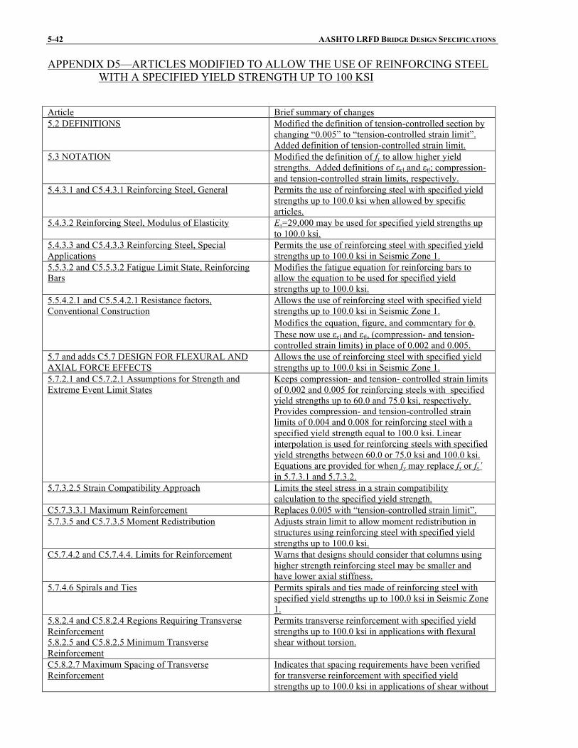
5-42 AASHTO LRFD BRIDGE DESIGN SPECIFICATIONS
APPENDIX D5—ARTICLES MODIFIED TO ALLOW THE USE OF REINFORCING STEEL WITH A SPECIFIED YIELD STRENGTH UP TO 100 KSI
Article Brief summary of changes 5.2 DEFINITIONS Modified the definition of tension-controlled section by
changing “0.005” to “tension-controlled strain limit”. Added definition of tension-controlled strain limit.
5.3 NOTATION Modified the definition of fy to allow higher yield strengths. Added definitions of %cl and %tl; compression- and tension-controlled strain limits, respectively.
5.4.3.1 and C5.4.3.1 Reinforcing Steel, General Permits the use of reinforcing steel with specified yield strengths up to 100.0 ksi when allowed by specific articles.
5.4.3.2 Reinforcing Steel, Modulus of Elasticity Es=29,000 may be used for specified yield strengths up to 100.0 ksi.
5.4.3.3 and C5.4.3.3 Reinforcing Steel, Special Applications
Permits the use of reinforcing steel with specified yield strengths up to 100.0 ksi in Seismic Zone 1.
5.5.3.2 and C5.5.3.2 Fatigue Limit State, Reinforcing Bars
Modifies the fatigue equation for reinforcing bars to allow the equation to be used for specified yield strengths up to 100.0 ksi.
5.5.4.2.1 and C5.5.4.2.1 Resistance factors, Conventional Construction
Allows the use of reinforcing steel with specified yield strengths up to 100.0 ksi in Seismic Zone 1. Modifies the equation, figure, and commentary for $. These now use %cl and %tl, (compression- and tension-controlled strain limits) in place of 0.002 and 0.005.
5.7 and adds C5.7 DESIGN FOR FLEXURAL AND AXIAL FORCE EFFECTS
Allows the use of reinforcing steel with specified yield strengths up to 100.0 ksi in Seismic Zone 1.
5.7.2.1 and C5.7.2.1 Assumptions for Strength and Extreme Event Limit States
Keeps compression- and tension- controlled strain limits of 0.002 and 0.005 for reinforcing steels with specified yield strengths up to 60.0 and 75.0 ksi, respectively. Provides compression- and tension-controlled strain limits of 0.004 and 0.008 for reinforcing steel with a specified yield strength equal to 100.0 ksi. Linear interpolation is used for reinforcing steels with specified yield strengths between 60.0 or 75.0 ksi and 100.0 ksi. Equations are provided for when fy may replace fs or fs’ in 5.7.3.1 and 5.7.3.2.
5.7.3.2.5 Strain Compatibility Approach Limits the steel stress in a strain compatibility calculation to the specified yield strength.
C5.7.3.3.1 Maximum Reinforcement Replaces 0.005 with “tension-controlled strain limit”. 5.7.3.5 and C5.7.3.5 Moment Redistribution Adjusts strain limit to allow moment redistribution in
structures using reinforcing steel with specified yield strengths up to 100.0 ksi.
C5.7.4.2 and C5.7.4.4. Limits for Reinforcement Warns that designs should consider that columns using higher strength reinforcing steel may be smaller and have lower axial stiffness.
5.7.4.6 Spirals and Ties
Permits spirals and ties made of reinforcing steel with specified yield strengths up to 100.0 ksi in Seismic Zone 1.
5.8.2.4 and C5.8.2.4 Regions Requiring Transverse Reinforcement 5.8.2.5 and C5.8.2.5 Minimum Transverse Reinforcement
Permits transverse reinforcement with specified yield strengths up to 100.0 ksi in applications with flexural shear without torsion.
C5.8.2.7 Maximum Spacing of Transverse Reinforcement
Indicates that spacing requirements have been verified for transverse reinforcement with specified yield strengths up to 100.0 ksi in applications of shear without
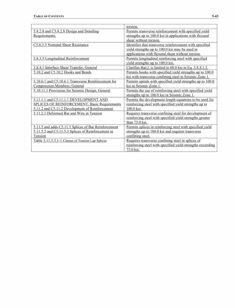
TABLE OF CONTENTS 5-43
torsion. 5.8.2.8 and C5.8.2.8 Design and Detailing Requirements.
Permits transverse reinforcement with specified yield strengths up to 100.0 ksi in applications with flexural shear without torsion.
C5.8.3.3 Nominal Shear Resistance Identifies that transverse reinforcement with specified yield strengths up to 100.0 ksi may be used in applications with flexural shear without torsion.
5.8.3.5 Longitudinal Reinforcement Permits longitudinal reinforcing steel with specified yield strengths up to 100.0 ksi.
5.8.4.1 Interface Shear Transfer, General Clarifies that fy is limited to 60.0 ksi in Eq. 5.8.4.1.3. 5.10.2 and C5.10.2 Hooks and Bends Permits hooks with specified yield strengths up to 100.0
ksi with transverse confining steel in Seismic Zone 1. 5.10.6.1 and C5.10.6.1 Transverse Reinforcement for Compression Members, General
Permits spirals with specified yield strengths up to 100.0 ksi in Seismic Zone 1.
5.10.11.1 Provisions for Seismic Design, General
Permits the use of reinforcing steel with specified yield strengths up to 100.0 ksi in Seismic Zone 1.
5.11.1.1 and C5.11.1.1 DEVELOPMENT AND SPLICES OF REINFORCEMENT, Basic Requirements 5.11.2 and C5.11.2 Development of Reinforcement
Permits the development length equations to be used for reinforcing steel with specified yield strengths up to 100.0 ksi.
5.11.2.1 Deformed Bar and Wire in Tension Requires transverse confining steel for development of reinforcing steel with specified yield strengths greater than 75.0 ksi.
5.11.5 and adds C5.11.5 Splices of Bar Reinforcement 5.11.5.3 and C5.11.5.3 Splices of Reinforcement in Tension
Permits splices in reinforcing steel with specified yield strengths up to 100.0 ksi and requires transverse confining steel.
Table 5.11.5.3.1-1 Classes of Tension Lap Splices
Requires transverse confining steel in splices of reinforcing steel with specified yield strengths exceeding 75.0 ksi.