Embed Size (px)
Citation preview
Appendix LOdd-numbered HomeworkProblems
Chapter 1
Section 1.2 Dimensions, Dimensional Homogeneity,and Units
1.1 Verify the dimensions, in both the FLT and MLT systems, ofthe following quantities, which appear in Table 1.1: (a) angularvelocity, (b) energy, (c) moment of inertia (area), (d) power, and(e) pressure.
1.3 If V is a velocity, / a length, and a fluid property havingdimensions of L2T�1, which of the following combinations aredimensionless: (a) V/ , (b) V// , (c) V 2 , (d) V// ?
1.5 If V is a velocity, determine the dimensions of Z, a, and G,which appear in the dimensionally homogeneous equation
1.7 The volume rate of flow, Q, through a pipe containing aslowly moving liquid is given by the equation
where R is the pipe radius, the pressure drop along the pipe,a fluid property called viscosity , and the length of pipe.What are the dimensions of the constant Would you classifythis equation as a general homogeneous equation? Explain.
1.9 According to information found in an old hydraulics book,the energy loss per unit weight of fluid flowing through a noz-zle connected to a hose can be estimated by the formula
where h is the energy loss per unit weight, D the hose diameter,d the nozzle tip diameter, V the fluid velocity in the hose, and gthe acceleration of gravity. Do you think this equation is valid inany system of units? Explain.
1.11 A formula to estimate the volume rate of flow, Q, flow-ing over a dam of length, B, is given by the equation
where H is the depth of the water above the top of the dam1called the head2. This formula gives Q in ft3/s when B and Hare in feet. Is the constant, 3.09, dimensionless? Would thisequation be valid if units other than feet and seconds were used?
1.13 Make use of Table 1.2 to express the following quanti-ties in SI units: (a) 10.2 in./min, (b) 4.81 slugs, (c) 3.02 lb,(d) 73.1 ft/s2, (e) 0.0234 lb�s/ft2.
1.15 Water flows from a large drainage pipe at a rate ofWhat is this volume rate of flow in (a) ,
(b) liters min, and (c) ft ?3�s�m3�s1200 gal�min.
Q � 3.09 BH3�2
h � 10.04 to 0.092 1D�d24V 2�2g
�/8?/1FL�2T2
�¢p
Q ��R4¢p
8�/
V � Z1a � 12 � G
����
�
Section 1.4 Measures of Fluid Mass and Weight
1.17 Obtain a photograph/image of a situation in which thedensity or specific weight of a fluid is important. Print thisphoto and write a brief paragraph that describes the situationinvolved.
1.19 The density of a certain liquid is 2.15 slugs/ft3. Determineits specific weight and specific gravity.
†1.21 Estimate the number of pounds of mercury it wouldtake to fill your bathtub. List all assumptions and show allcalculations.
†1.23 The presence of raindrops in the air during a heavy rain-storm increases the average density of the air–water mixture.Estimate by what percent the average air–water density isgreater than that of just still air. State all assumptions and showcalculations.
*1.25 The variation in the density of water, �, with temperature,T, in the range of 20 °C � T � 50 °C, is given in the followingtable.
Density (kg/m3) 998.2 997.1 995.7 994.1 992.2 990.2 988.1
Temperature (C) 20 25 30 35 40 45 50
Use these data to determine an empirical equation of the form� � c1 � c2T � c3T
2, which can be used to predict the densityover the range indicated. Compare the predicted values withthe data given. What is the density of water at 42.1 C?
1.27 A mountain climber’s oxygen tank contains 1 lb of oxy-gen when he begins his trip at sea level where the accelerationof gravity is 32.174 ft/s2. What is the weight of the oxygen in thetank when he reaches the top of Mt. Everest where the acceler-ation of gravity is 32.082 ft/s2? Assume that no oxygen has beenremoved from the tank; it will be used on the descent portion ofthe climb.
Section 1.5 Ideal Gas Law
1.29 Some experiments are being conducted in a laboratory inwhich the air temperature is 27 C and the atmospheric pressureis 14.3 psia. Determine the density of the air. Express your an-swers in slugs/ft3 and in kg/m3.
1.31 Nitrogen is compressed to a density of 4 kg/m3 under anabsolute pressure of 400 kPa. Determine the temperature in de-grees Celsius.
1.33 A tire having a volume of 3 ft3 contains air at a gage pres-sure of 26 psi and a temprature of 70 F. Determine the densityof the air and the weight of the air contained in the tire.
1
Section 1.6 Viscosity (also see Lab Problems 1.74and 1.75)
1.35 Obtain a photograph/image of a situation in which the vis-cosity of a fluid is important. Print this photo and write a briefparagraph that describes the situation involved.
1.37 A liquid has a specific weight of 59 lb/ft3 and a dynamicviscosity of 2.75 lb�s/ft2. Determine its kinematic viscosity.
1.39 The time, t, it takes to pour a liquid from a container de-pends on several factors, including the kinematic viscosity, �,of the liquid. (See Video V1.3.) In some laboratory tests, vari-ous oils having the same density but different viscosities werepoured at a fixed tipping rate from small 150-ml beakers. Thetime required to pour 100 ml of the oil was measured, and itwas found that an approximate equation for the pouring timein seconds was t � 1 � 9 102� � 8 103�2 with � in m2/s.(a) Is this a general homogeneous equation? Explain. (b)Compare the time it would take to pour 100 ml of SAE 30 oilfrom a 150-ml beaker at 0 C to the corresponding time at atemperature of 60 C. Make use of Fig. B.2 in Appendix B forviscosity data.
1.41 The viscosity of a certain fluid is poise. Deter-mine its viscosity in both SI and BG units.
1.43 Calculate the Reynolds number for the flow of water andfor air through a 3-mm-diameter tube if the mean velocity is 2 m/s and the temperature is 30 C in both cases (see Example1.3). Assume the air is at standard atmospheric pressure.
1.45 As shown in Video V1.4, the no-slip condition meansthat a fluid “sticks” to a solid surface. This is true for bothfixed and moving surfaces. Let two layers of fluid be draggedalong by the motion of an upper plate as shown in Fig. P1.45.The bottom plate is stationary. The top fluid puts a shearstress on the upper plate, and the lower fluid puts a shear stresson the botton plate. Determine the ratio of these two shearstresses.
5 10�4
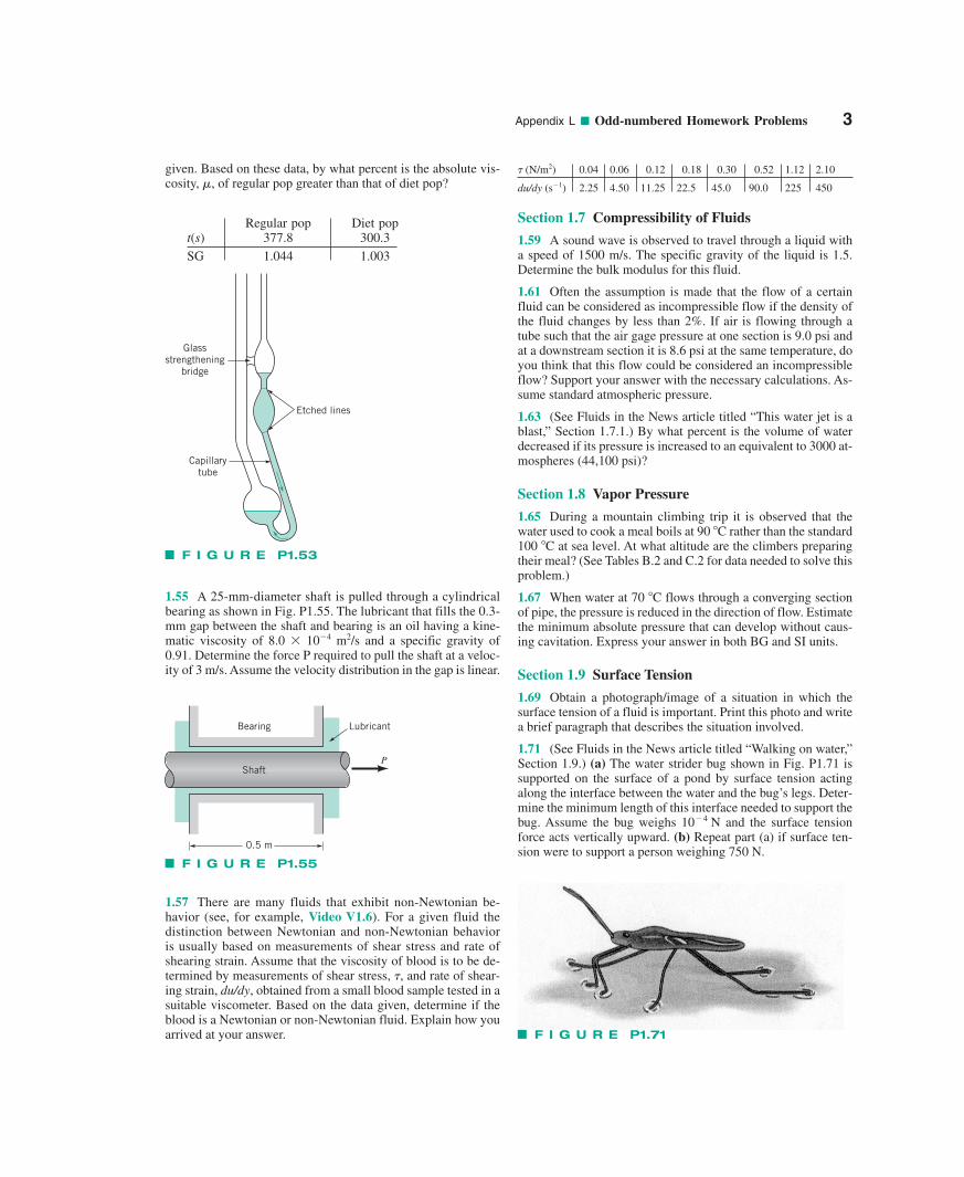
1.49 A layer of water flows down an inclined fixed surfacewith the velocity profile shown in Fig. P1.49. Determine themagnitude and direction of the shearing stress that the water ex-erts on the fixed surface for U � 3 m/s and h � 0.1 m.
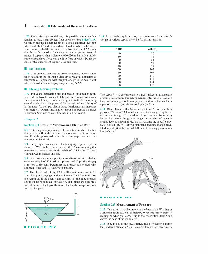
1.51 A new computer drive is proposed to have a disc, asshown in Fig. P1.51. The disc is to rotate at 10,000 rpm, and thereader head is to be positioned 0.0005 in. above the surface ofthe disc. Estimate the shearing force on the reader head as resultof the air between the disc and the head.
1.53 The viscosity of a soft drink was determined by using acapillary tube viscometer similar to that shown in Fig. P1.53and Video V1.5. For this device the kinematic viscosity, v, is di-rectly proportional to the time, t, that it takes for a given amountof liquid to flow through a small capillary tube. That is, v � Kt.The following data were obtained from regular pop and dietpop. The corresponding measured specific gravities are also
2 Appendix L ■ Odd-numbered Homework Problems
Fluid 1 0.02 m
Fluid 2 0.02 m
2 m/s
3 m/s
1 = 0.4 N s/m2μ
2 = 0.2 N s/m2μ
U
.
.
F I G U R E P1.45
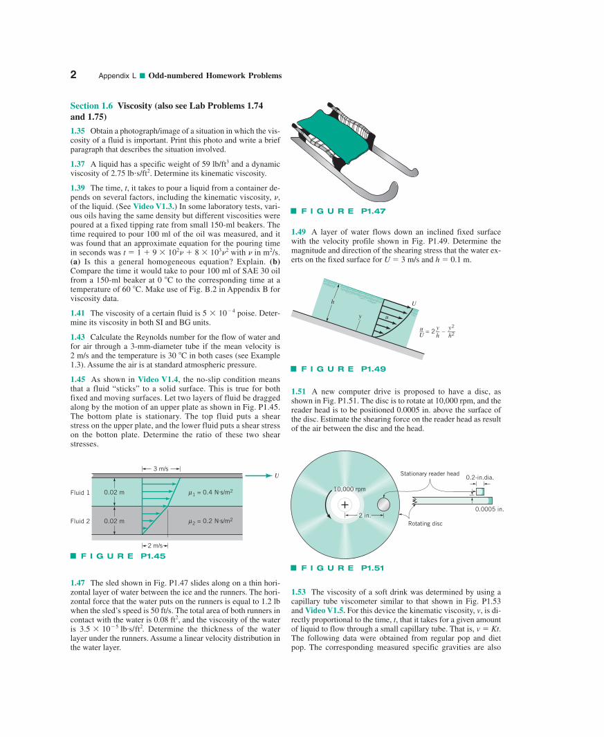
1.47 The sled shown in Fig. P1.47 slides along on a thin hori-zontal layer of water between the ice and the runners. The hori-zontal force that the water puts on the runners is equal to 1.2 lbwhen the sled’s speed is 50 ft/s. The total area of both runners incontact with the water is , and the viscosity of the wateris Determine the thickness of the waterlayer under the runners. Assume a linear velocity distribution inthe water layer.
3.5 10�5 lb.s/ft2.0.08 ft2
F I G U R E P1.47
h
y u
U
u–U
= 2y–h
–y2––h2
F I G U R E P1.49
0.0005 in.
Rotating disc
10,000 rpm
2 in.
0.2-in.dia.Stationary reader head
F I G U R E P1.51
Appendix L ■ Odd-numbered Homework Problems 3
1.55 A 25-mm-diameter shaft is pulled through a cylindricalbearing as shown in Fig. P1.55. The lubricant that fills the 0.3-mm gap between the shaft and bearing is an oil having a kine-matic viscosity of 8.0 10�4 m2/s and a specific gravity of0.91. Determine the force P required to pull the shaft at a veloc-ity of 3 m/s. Assume the velocity distribution in the gap is linear.
1.57 There are many fluids that exhibit non-Newtonian be-havior (see, for example, Video V1.6). For a given fluid thedistinction between Newtonian and non-Newtonian behavioris usually based on measurements of shear stress and rate ofshearing strain. Assume that the viscosity of blood is to be de-termined by measurements of shear stress, �, and rate of shear-ing strain, du/dy, obtained from a small blood sample tested in asuitable viscometer. Based on the data given, determine if theblood is a Newtonian or non-Newtonian fluid. Explain how youarrived at your answer.
� (N/m2) 0.04 0.06 0.12 0.18 0.30 0.52 1.12 2.10
du/dy (s�1) 2.25 4.50 11.25 22.5 45.0 90.0 225 450
Section 1.7 Compressibility of Fluids
1.59 A sound wave is observed to travel through a liquid witha speed of 1500 m/s. The specific gravity of the liquid is 1.5.Determine the bulk modulus for this fluid.
1.61 Often the assumption is made that the flow of a certainfluid can be considered as incompressible flow if the density ofthe fluid changes by less than 2%. If air is flowing through atube such that the air gage pressure at one section is 9.0 psi andat a downstream section it is 8.6 psi at the same temperature, doyou think that this flow could be considered an incompressibleflow? Support your answer with the necessary calculations. As-sume standard atmospheric pressure.
1.63 (See Fluids in the News article titled “This water jet is ablast,” Section 1.7.1.) By what percent is the volume of waterdecreased if its pressure is increased to an equivalent to 3000 at-mospheres (44,100 psi)?
Section 1.8 Vapor Pressure
1.65 During a mountain climbing trip it is observed that thewater used to cook a meal boils at 90 C rather than the standard100 C at sea level. At what altitude are the climbers preparingtheir meal? (See Tables B.2 and C.2 for data needed to solve thisproblem.)
1.67 When water at 70 C flows through a converging sectionof pipe, the pressure is reduced in the direction of flow. Estimatethe minimum absolute pressure that can develop without caus-ing cavitation. Express your answer in both BG and SI units.
Section 1.9 Surface Tension
1.69 Obtain a photograph/image of a situation in which thesurface tension of a fluid is important. Print this photo and writea brief paragraph that describes the situation involved.
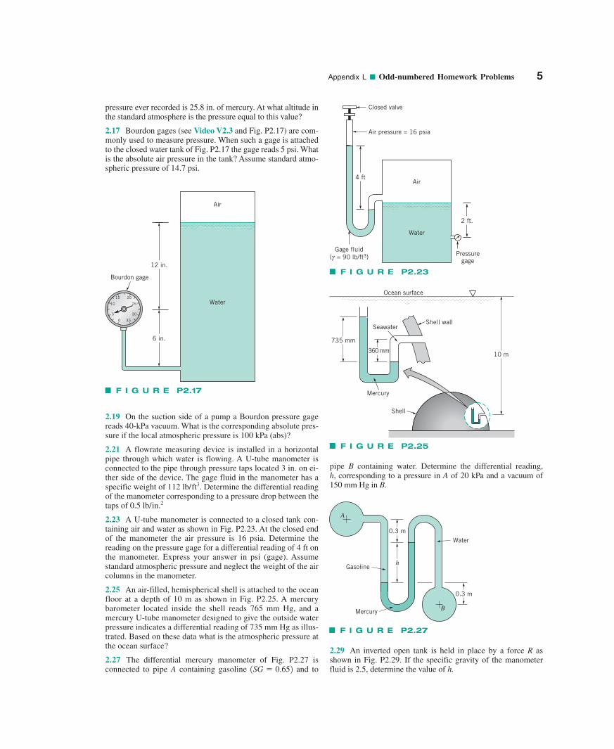
1.71 (See Fluids in the News article titled “Walking on water,”Section 1.9.) (a) The water strider bug shown in Fig. P1.71 issupported on the surface of a pond by surface tension actingalong the interface between the water and the bug’s legs. Deter-mine the minimum length of this interface needed to support thebug. Assume the bug weighs and the surface tensionforce acts vertically upward. (b) Repeat part (a) if surface ten-sion were to support a person weighing 750 N.
10�4 N
Regular pop Diet popt(s) 377.8 300.3SG 1.044 1.003
Glassstrengthening
bridge
Capillarytube
Etched lines
F I G U R E P1.53
F I G U R E P1.55
Shaft
Bearing Lubricant
0.5 m
P
given. Based on these data, by what percent is the absolute vis-cosity, �, of regular pop greater than that of diet pop?
F I G U R E P1.71
4 Appendix L ■ Odd-numbered Homework Problems
1.73 Under the right conditions, it is possible, due to surfacetension, to have metal objects float on water. (See Video V1.9.)Consider placing a short length of a small-diameter steel (sp.wt. � 490 lb/ft3) rod on a surface of water. What is the maxi-mum diameter that the rod can have before it will sink? Assumethat the surface tension forces act vertically upward. Note: Astandard paper clip has a diameter of 0.036 in. Partially unfold apaper clip and see if you can get it to float on water. Do the re-sults of this experiment support your analysis?
■ Lab Problems
1.75 This problem involves the use of a capillary tube viscome-ter to determine the kinematic viscosity of water as a function oftemperature. To proceed with this problem, go to the book’s website, www.wiley.com/college/young, or WileyPLUS.
■ Lifelong Learning Problems
1.77 For years, lubricating oils and greases obtained by refin-ing crude oil have been used to lubricate moving parts in a widevariety of machines, motors, and engines. With the increasingcost of crude oil and the potential for the reduced availability ofit, the need for non-petroleum-based lubricants has increasedconsiderably. Obtain information about non-petroleum-basedlubricants. Summarize your findings in a brief report.
Chapter 2
Section 2.3 Pressure Variation in a Fluid at Rest
2.1 Obtain a photograph/image of a situation in which the factthat in a static fluid the pressure increases with depth is impor-tant. Print this photo and write a brief paragraph that describesthe situation involved.
2.3 Bathyscaphes are capable of submerging to great depths inthe ocean. What is the pressure at a depth of 5 km, assuming thatseawater has a constant specific weight of Expressyour answer in pascals and psi.
2.5 In a certain chemical plant, a closed tank contains ethyl al-cohol to a depth of 50 ft. Air at a pressure of 25 psi fills the gapat the top of the tank. Determine the pressure at a closed valveattached to the tank 10 ft above its bottom.
2.7 The closed tank of Fig. P2.7 is filled with water and is 5 ftlong. The pressure gage on the tank reads 7 psi. Determine (a)the height, h, in the open water column, (b) the gage pressureacting on the bottom tank surface AB, and (c) the absolute pres-sure of the air in the top of the tank if the local atmospheric pres-sure is 14.7 psia.
10.1 kN/m3?
*2.9 In a certain liquid at rest, measurements of the specificweight at various depths show the following variation:
Water
Air
7 psi
h
Open
BA
2 ft
2 ft
F I G U R E P2.7
h (ft) �(lb/ft3)
0 7010 7620 8430 9140 9750 10260 10770 11080 11290 114
100 115
The depth h � 0 corresponds to a free surface at atmosphericpressure. Determine, through numerical integration of Eq. 2.4,the corresponding variation in pressure and show the results ona plot of pressure (in psf) versus depth (in feet).
2.11 (See Fluids in the News article titled “Giraffe’s bloodpressure,” Section 2.3.1.) (a) Determine the change in hydrosta-tic pressure in a giraffe’s head as it lowers its head from eatingleaves 6 m above the ground to getting a drink of water atground level as shown in Fig. P2.11. Assume the specific grav-ity of blood is . (b) Compare the pressure change calcu-lated in part (a) to the normal 120 mm of mercury pressure in ahuman’s heart.
SG � 1
6 m
Water
F I G U R E P2.11
Section 2.5 Measurement of Pressure
2.13 On a given day, a barometer at the base of the WashingtonMonument reads 29.97 in. of mercury. What would the barometerreading be when you carry it up to the observation deck 500 ftabove the base of the monument?
2.15 (See Fluids in the News article titled “Weather, barome-ters, and bars,” Section 2.5.) The record low sea-level barometric
Appendix L ■ Odd-numbered Homework Problems 5
pressure ever recorded is 25.8 in. of mercury. At what altitude inthe standard atmosphere is the pressure equal to this value?
2.17 Bourdon gages (see Video V2.3 and Fig. P2.17) are com-monly used to measure pressure. When such a gage is attachedto the closed water tank of Fig. P2.17 the gage reads 5 psi. Whatis the absolute air pressure in the tank? Assume standard atmo-spheric pressure of 14.7 psi.
pipe B containing water. Determine the differential reading,h, corresponding to a pressure in A of 20 kPa and a vacuum of 150 mm Hg in B.
Air
Water
12 in.
6 in.
10 25
5 30
2015
350
Bourdon gage
F I G U R E P2.17
2.19 On the suction side of a pump a Bourdon pressure gagereads 40-kPa vacuum. What is the corresponding absolute pres-sure if the local atmospheric pressure is 100 kPa (abs)?
2.21 A flowrate measuring device is installed in a horizontalpipe through which water is flowing. A U-tube manometer isconnected to the pipe through pressure taps located 3 in. on ei-ther side of the device. The gage fluid in the manometer has aspecific weight of . Determine the differential readingof the manometer corresponding to a pressure drop between thetaps of
2.23 A U-tube manometer is connected to a closed tank con-taining air and water as shown in Fig. P2.23. At the closed endof the manometer the air pressure is 16 psia. Determine thereading on the pressure gage for a differential reading of 4 ft onthe manometer. Express your answer in psi (gage). Assumestandard atmospheric pressure and neglect the weight of the aircolumns in the manometer.
2.25 An air-filled, hemispherical shell is attached to the oceanfloor at a depth of 10 m as shown in Fig. P2.25. A mercurybarometer located inside the shell reads 765 mm Hg, and amercury U-tube manometer designed to give the outside waterpressure indicates a differential reading of 735 mm Hg as illus-trated. Based on these data what is the atmospheric pressure atthe ocean surface?
2.27 The differential mercury manometer of Fig. P2.27 isconnected to pipe A containing gasoline and to1SG � 0.652
0.5 lb/in.2
112 lb/ft3
F I G U R E P2.23
Air
Water
4 ft
Air pressure = 16 psia
Closed valve
Gage fluid (g = 90 lb/ft3) Pressure
gage
2 ft.
F I G U R E P2.25
Mercury
Shell
SeawaterShell wall
Ocean surface
735 mm
360 mm 10 m
F I G U R E P2.27
Gasoline
Mercury
Water
A
B
0.3 m
h
0.3 m
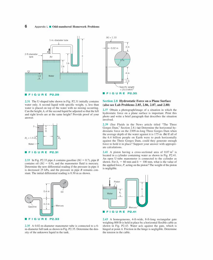
2.29 An inverted open tank is held in place by a force R asshown in Fig. P2.29. If the specific gravity of the manometerfluid is 2.5, determine the value of h.
6 Appendix L ■ Odd-numbered Homework Problems
2.31 The U-shaped tube shown in Fig. P2.31 initially containswater only. A second liquid with specific weight, , less thanwater is placed on top of the water with no mixing occurring.Can the height, h, of the second liquid be adjusted so that the leftand right levels are at the same height? Provide proof of youranswer.
�Section 2.8 Hydrostatic Force on a Plane Surface(also see Lab Problems 2.85, 2.86, 2.87, and 2.88)
2.37 Obtain a photograph/image of a situation in which thehydrostatic force on a plane surface is important. Print thisphoto and write a brief paragraph that describes the situationinvolved.
2.39 (See Fluids in the News article titled “The ThreeGorges Dam,” Section 2.8.) (a) Determine the horizontal hy-drostatic force on the 2309-m-long Three Gorges Dam whenthe average depth of the water against it is 175 m. (b) If all ofthe 6.4 billion people on Earth were to push horizontallyagainst the Three Gorges Dam, could they generate enoughforce to hold it in place? Support your answer with appropri-ate calculations.
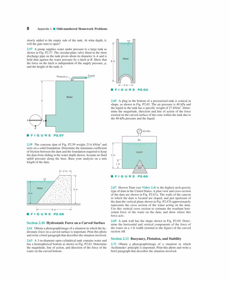
2.41 A piston having a cross-sectional area of islocated in a cylinder containing water as shown in Fig. P2.41.An open U-tube manometer is connected to the cylinder asshown. For what is the value ofthe applied force, P, acting on the piston? The weight of the pistonis negligible.
h1 � 60 mm and h � 100 mm,
0.07 m2
F I G U R E P2.29
h
3 ft
1 ft
Air
1-in.-diameter tube
2-ft-diametertank
Water
2 ft
R
F I G U R E P2.31
Water
γ
D1 = 1.5 D2 D2
h
2.33 In Fig. P2.33 pipe A contains gasoline (SG � 0.7), pipe Bcontains oil (SG � 0.9), and the manometer fluid is mercury.Determine the new differential reading if the pressure in pipe Ais decreased 25 kPa, and the pressure in pipe B remains con-stant. The initial differential reading is 0.30 m as shown.
F I G U R E P2.33
A
B
Oil
MercuryGasoline
0.4 m
0.3 m
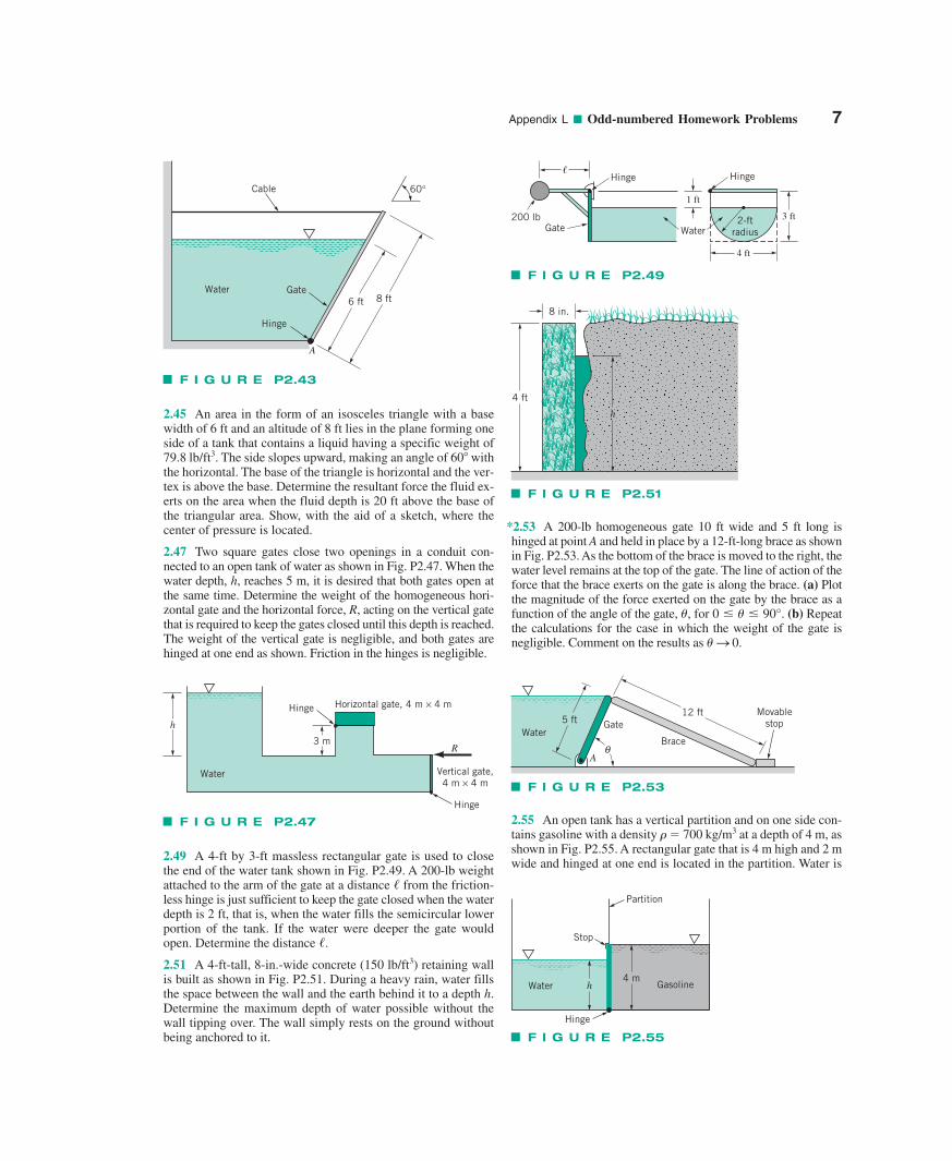
2.35 A 0.02-m-diameter manometer tube is connected to a 6-m-diameter full tank as shown in Fig. P2.35. Determine the den-sity of the unknown liquid in the tank.
F I G U R E P2.35
SG = 1.10
6 m
1 m
4 m
Specific weight= 25.0 kN/m3
3 m0.02 m
F I G U R E P2.41
PistonP
h
h1Water
Mercury
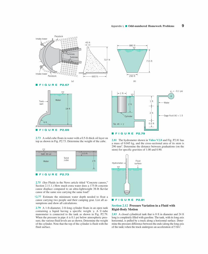
2.43 A homogeneous, 4-ft-wide, 8-ft-long rectangular gateweighing 800 lb is held in place by a horizontal flexible cable asshown in Fig. P2.43. Water acts against the gate, which ishinged at point A. Friction in the hinge is negligible. Determinethe tension in the cable.
Appendix L ■ Odd-numbered Homework Problems 7
*2.53 A 200-lb homogeneous gate 10 ft wide and 5 ft long ishinged at point A and held in place by a 12-ft-long brace as shownin Fig. P2.53. As the bottom of the brace is moved to the right, thewater level remains at the top of the gate. The line of action of theforce that the brace exerts on the gate is along the brace. (a) Plotthe magnitude of the force exerted on the gate by the brace as afunction of the angle of the gate, (b) Repeatthe calculations for the case in which the weight of the gate isnegligible. Comment on the results as � S 0.
�, for 0 � � � 90°.
2.45 An area in the form of an isosceles triangle with a basewidth of 6 ft and an altitude of 8 ft lies in the plane forming oneside of a tank that contains a liquid having a specific weight of79.8 lb/ft3. The side slopes upward, making an angle of 60 withthe horizontal. The base of the triangle is horizontal and the ver-tex is above the base. Determine the resultant force the fluid ex-erts on the area when the fluid depth is 20 ft above the base ofthe triangular area. Show, with the aid of a sketch, where thecenter of pressure is located.
2.47 Two square gates close two openings in a conduit con-nected to an open tank of water as shown in Fig. P2.47. When thewater depth, h, reaches 5 m, it is desired that both gates open atthe same time. Determine the weight of the homogeneous hori-zontal gate and the horizontal force, R, acting on the vertical gatethat is required to keep the gates closed until this depth is reached.The weight of the vertical gate is negligible, and both gates arehinged at one end as shown. Friction in the hinges is negligible.
F I G U R E P2.43
Cable
Gate
Hinge
Water6 ft 8 ft
A
60°
F I G U R E P2.47
h
3 m
Hinge
Water
Hinge
Horizontal gate, 4 m × 4 m
Vertical gate,4 m × 4 m
R
2.49 A 4-ft by 3-ft massless rectangular gate is used to closethe end of the water tank shown in Fig. P2.49. A 200-lb weightattached to the arm of the gate at a distance from the friction-less hinge is just sufficient to keep the gate closed when the waterdepth is 2 ft, that is, when the water fills the semicircular lowerportion of the tank. If the water were deeper the gate wouldopen. Determine the distance .
2.51 A 4-ft-tall, 8-in.-wide concrete (150 lb/ft3) retaining wallis built as shown in Fig. P2.51. During a heavy rain, water fillsthe space between the wall and the earth behind it to a depth h.Determine the maximum depth of water possible without thewall tipping over. The wall simply rests on the ground withoutbeing anchored to it.
/
/
F I G U R E P2.49
Hinge
Gate Water200 lb
Hinge
2-ftradius
1 ft
3 ft
4 ft
�
F I G U R E P2.51
8 in.
h
4 ft
F I G U R E P2.53
12 ft
Brace
Gate5 ftWater
Aθ
Movablestop
2.55 An open tank has a vertical partition and on one side con-tains gasoline with a density � � 700 kg/m3 at a depth of 4 m, asshown in Fig. P2.55. A rectangular gate that is 4 m high and 2 mwide and hinged at one end is located in the partition. Water is
F I G U R E P2.55
Stop
Partition
Hinge
Water Gasoline4 m
h
slowly added to the empty side of the tank. At what depth, h,will the gate start to open?
2.57 A pump supplies water under pressure to a large tank asshown in Fig. P2.57. The circular-plate valve fitted in the shortdischarge pipe on the tank pivots about its diameter A–A and isheld shut against the water pressure by a latch at B. Show thatthe force on the latch is independent of the supply pressure, p,and the height of the tank, h.
2.65 A plug in the bottom of a pressurized tank is conical inshape, as shown in Fig. P2.65. The air pressure is 40 kPa andthe liquid in the tank has a specific weight of 27 kN/m3. Deter-mine the magnitude, direction and line of action of the forceexerted on the curved surface of the cone within the tank due tothe 40-kPa pressure and the liquid.
8 Appendix L ■ Odd-numbered Homework Problems
Section 2.10 Hydrostatic Force on a Curved Surface
2.61 Obtain a photograph/image of a situation in which the hy-drostatic force on a curved surface is important. Print this photoand write a brief paragraph that describes the situation involved.
2.63 A 3-m-diameter open cylindrical tank contains water andhas a hemispherical bottom as shown in Fig. P2.63. Determinethe magnitude, line of action, and direction of the force of thewater on the curved bottom.
F I G U R E P2.57
Water
SupplyPressure p
h
AA
B
F I G U R E P2.59
5 m
2 m
4 m
Water
6 m
2.59 The concrete dam of Fig. P2.59 weighs 23.6 kN/m3 andrests on a solid foundation. Determine the minimum coefficientof friction between the dam and the foundation required to keepthe dam from sliding at the water depth shown. Assume no fluiduplift pressure along the base. Base your analysis on a unitlength of the dam.
F I G U R E P2.63
Water8 m
3 m
F I G U R E P2.65
Air
Liquid
40 kPa
3 m
1 m
60°
2.67 Hoover Dam (see Video 2.4) is the highest arch-gravitytype of dam in the United States. A plan view and cross sectionof the dam are shown in Fig. P2.67a. The walls of the canyonin which the dam is located are sloped, and just upstream ofthe dam the vertical plane shown in Fig. P2.67b approximatelyrepresents the cross section of the water acting on the dam.Use this vertical cross section to estimate the resultant hori-zontal force of the water on the dam, and show where thisforce acts.
2.69 A tank wall has the shape shown in Fig. P2.69. Deter-mine the horizontal and vertical components of the force ofthe water on a 1-ft width (normal to the figure) of the curvedsection AB.
Section 2.11 Buoyancy, Flotation, and Stability
2.71 Obtain a photograph/image of a situation in whichArchimedes’ principle is important. Print this photo and write abrief paragraph that describes the situation involved.
Appendix L ■ Odd-numbered Homework Problems 9
2.73 A solid cube floats in water with a 0.5-ft-thick oil layer ontop as shown in Fig. P2.73. Determine the weight of the cube. 2.81 The hydrometer shown in Video V2.8 and Fig. P2.81 has
a mass of 0.045 kg, and the cross-sectional area of its stem is290 mm2. Determine the distance between graduations (on thestem) for specific gravities of 1.00 and 0.90.
F I G U R E P2.69
18 ft
Tankwall
Water
6 ft
B
A
F I G U R E P2.79
1 ft
2 ft
0.5 ft
2 ft
1 ft
Sp. wt. = γ
Cylinder Gage fluid SG = 1.5
Water
A
pa = –0.1 psi
F I G U R E P2.81
FluidsurfaceHydrometer
F I G U R E P2.73
Water
SAE 30 oil
Solidcube
0.5 ft
2 ft
F I G U R E P2.67
715 ft
Intake tower
Intake tower
Penstock
Penstock
TurbinesTurbines
660 ft
727 ft
45 ft
(a) (b)
880 ft
290 ft
2.75 (See Fluids in the News article titled “Concrete canoes,”Section 2.11.1.) How much extra water does a 175-lb concretecanoe displace compared to an ultra-lightweight 38-lb Kevlarcanoe of the same size carrying the same load?
†2.77 Estimate the minimum water depth needed to float a canoe carrying two people and their camping gear. List all as-sumptions and show all calculations.
2.79 A 1-ft-diameter, 2-ft-long cylinder floats in an open tankcontaining a liquid having a specific weight �. A U-tubemanometer is connected to the tank as shown in Fig. P2.79.When the pressure in pipe A is 0.1 psi below atmospheric pres-sure, the various fluid levels are as shown. Determine the weightof the cylinder. Note that the top of the cylinder is flush with thefluid surface.
Section 2.12 Pressure Variation in a Fluid withRigid-Body Motion
2.83 A closed cylindrical tank that is 8 ft in diameter and 24 ftlong is completely filled with gasoline. The tank, with its long axishorizontal, is pulled by a truck along a horizontal surface. Deter-mine the pressure difference between the ends (along the long axisof the tank) when the truck undergoes an acceleration of 5 ft/s2.
10 Appendix L ■ Odd-numbered Homework Problems
■ Lab Problems
2.85 This problem involves the force needed to open a gate thatcovers an opening in the side of a water-filled tank. To proceedwith this problem go to the book’s web site, www.wiley.com/college/young, or WileyPLUS.
2.87 This problem involves determining the weight needed tohold down an open-bottom box that has slanted sides when thebox is filled with water. To proceed with this problem, go to thebook’s web site, www.wiley.com/college/young, or WileyPLUS.
■ Lifelong Learning Problems
2.89 Although it is relatively easy to calculate the net hydrostaticpressure force on a dam, it is not necessarily easy to design andconstruct an appropriate, long-lasting, inexpensive dam. In fact,inspection of older dams has revealed that many of them are inperil of collapse unless corrective action is soon taken. Obtain in-formation about the severity of the poor conditions of older damsthroughout the country. Summarize your findings in a brief report.
2.91 Liquid-filled manometers and Bourdon tube pressure gageshave been the mainstay for measuring pressure for many years.However, for many modern applications, these tried-and-true de-vices are not sufficient. For example, various new uses need small,accurate, inexpensive pressure transducers with digital outputs.Obtain information about some of the new concepts used for pres-sure measurement. Summarize your findings in a brief report.
Chapter 3
Section 3.2 F � ma Along a Streamline
3.1 Water flows steadily through the variable area horizontalpipe shown in Fig. P3.1. The centerline velocity is given by V �10(1�x)î ft/s, where x is in feet. Viscous effects are neglected. (a)Determine the pressure gradient, 0p/0x (as a function of x), neededto produce this flow. (b) If the pressure at section (1) is 50 psi, de-termine the pressure at (2) by (i) integration of the pressure gradi-ent obtained in (a) and (ii) application of the Bernoulli equation.
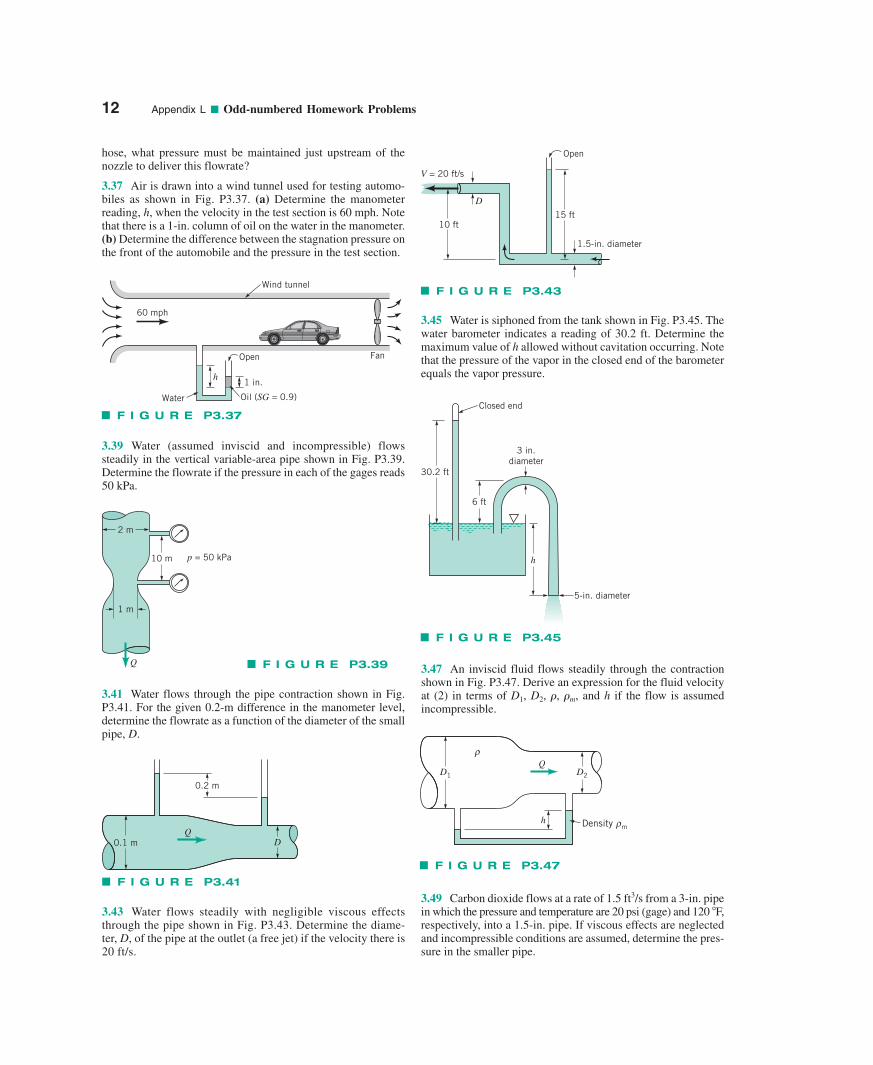
3.3 An incompressible fluid flows steadily past a circularcylinder as shown in Fig. P3.3 (see Video V3.7 also). The fluidvelocity along the dividing streamline is1�q � x � �a2
found to be where a is the radius of thecylinder and is the upstream velocity. (a) Determine the pres-sure gradient along this streamline. (b) If the upstream pressureis integrate the pressure gradient to obtain the pressure p(x)for (c) Show from the result of part (b) that thepressure at the stagnation point is as ex-pected from the Bernoulli equation.
3.5 What pressure gradient along the streamline, dp/ds, is re-quired to accelerate water upward in a vertical pipe at a rate of30 ft/s2? What is the answer if the flow is downward?
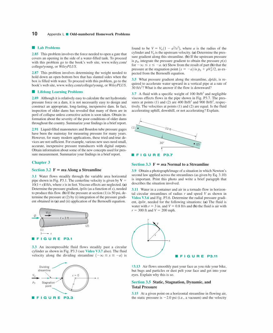
3.7 A fluid with a specific weight of 100 lb/ft3 and negligibleviscous effects flows in the pipe shown in Fig. P3.7. The pres-sures at points (1) and (2) are 400 lb/ft2 and 900 lb/ft2, respec-tively. The velocities at points (1) and (2) are equal. Is the fluidaccelerating uphill, downhill, or not accelerating? Explain.
p0 � �V 20 /2,1x � �a2
�q � x � �a.p0,
V0
V � V0 11 � a2/x22,
Section 3.3 F � ma Normal to a Streamline
3.9 Obtain a photograph/image of a situation in which Newton’ssecond law applied across the streamlines (as given by Eq. 3.10)is important. Print this photo and write a brief paragrph that describes the situation involved.
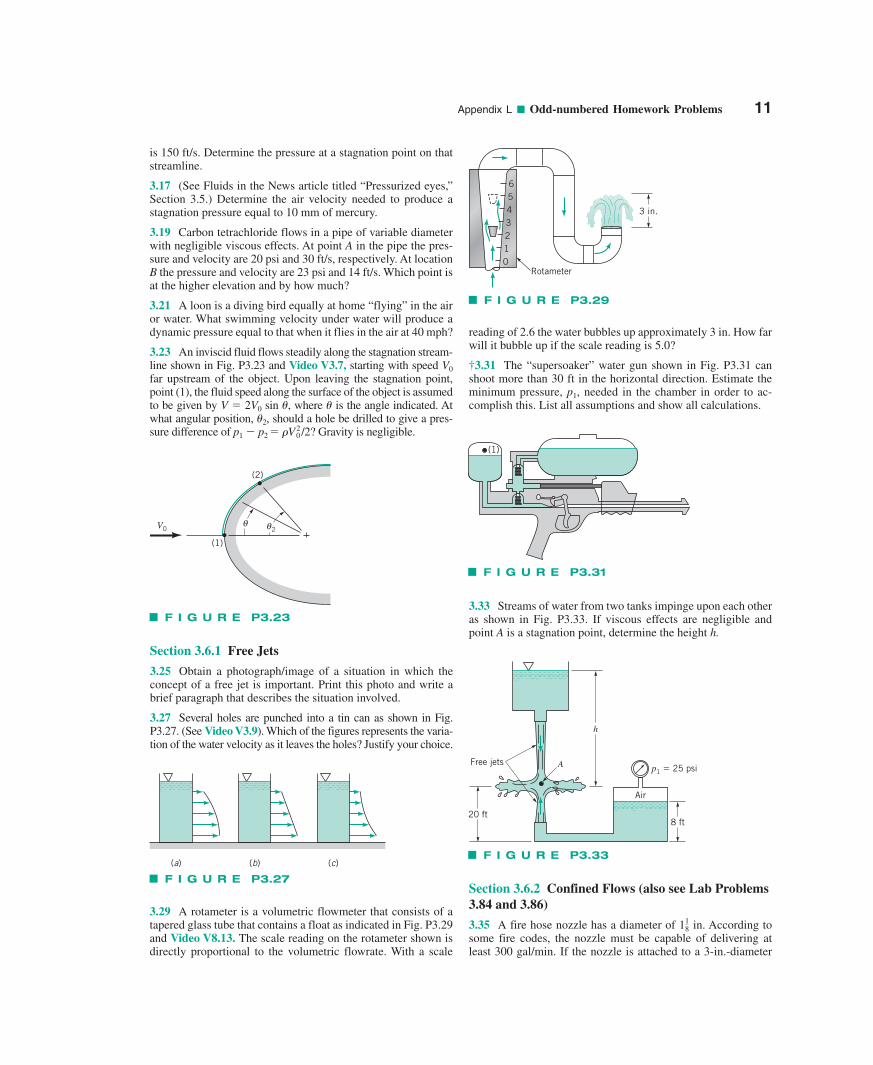
3.11 Water in a container and air in a tornado flow in horizon-tal circular streamlines of radius r and speed V as shown inVideo V3.6 and Fig. P3.6. Determine the radial pressure gradi-ent, 0p/0r, needed for the following situations: (a) The fluid iswater with r � 3 in. and V � 0.8 ft/s and (b) the fluid is air withr � 300 ft and V � 200 mph.
†3.13 Air flows smoothly past your face as you ride your bike,but bugs and particles or dust pelt your face and get into youreyes. Explain why this is so.
Section 3.5 Static, Stagnation, Dynamic, and Total Pressure
3.15 At a given point on a horizontal streamline in flowing air,the static pressure is �2.0 psi (i.e., a vacuum) and the velocity
QV(x)
(1)(2)
� = 3 ft
x
F I G U R E P3.1
(2)
(1) 10 ft
30
F I G U R E P3.7
V
r
x
y
F I G U R E P3.11
F I G U R E P3.3
Dividingstreamline
Stagnationpoint
x � 0x
a
VO
pO
Appendix L ■ Odd-numbered Homework Problems 11
is 150 ft/s. Determine the pressure at a stagnation point on thatstreamline.
3.17 (See Fluids in the News article titled “Pressurized eyes,”Section 3.5.) Determine the air velocity needed to produce astagnation pressure equal to 10 mm of mercury.
3.19 Carbon tetrachloride flows in a pipe of variable diameterwith negligible viscous effects. At point A in the pipe the pres-sure and velocity are 20 psi and 30 ft/s, respectively. At locationB the pressure and velocity are 23 psi and 14 ft/s. Which point isat the higher elevation and by how much?
3.21 A loon is a diving bird equally at home “flying” in the airor water. What swimming velocity under water will produce adynamic pressure equal to that when it flies in the air at 40 mph?
3.23 An inviscid fluid flows steadily along the stagnation stream-line shown in Fig. P3.23 and Video V3.7, starting with speed V0
far upstream of the object. Upon leaving the stagnation point,point (1), the fluid speed along the surface of the object is assumedto be given by V � 2V0 sin �, where � is the angle indicated. Atwhat angular position, �2, should a hole be drilled to give a pres-sure difference of p1 � p2 � �V0
2/2? Gravity is negligible.
Section 3.6.1 Free Jets
3.25 Obtain a photograph/image of a situation in which theconcept of a free jet is important. Print this photo and write abrief paragraph that describes the situation involved.
3.27 Several holes are punched into a tin can as shown in Fig.P3.27. (See Video V3.9). Which of the figures represents the varia-tion of the water velocity as it leaves the holes? Justify your choice.
3.29 A rotameter is a volumetric flowmeter that consists of atapered glass tube that contains a float as indicated in Fig. P3.29and Video V8.13. The scale reading on the rotameter shown isdirectly proportional to the volumetric flowrate. With a scale
reading of 2.6 the water bubbles up approximately 3 in. How farwill it bubble up if the scale reading is 5.0?
†3.31 The “supersoaker” water gun shown in Fig. P3.31 canshoot more than 30 ft in the horizontal direction. Estimate theminimum pressure, , needed in the chamber in order to ac-complish this. List all assumptions and show all calculations.
p1
3.33 Streams of water from two tanks impinge upon each otheras shown in Fig. P3.33. If viscous effects are negligible andpoint A is a stagnation point, determine the height h.
Section 3.6.2 Confined Flows (also see Lab Problems3.84 and 3.86)
3.35 A fire hose nozzle has a diameter of 1 in. According tosome fire codes, the nozzle must be capable of delivering atleast 300 gal/min. If the nozzle is attached to a 3-in.-diameter
18
θ θ2
(2)
(1)
V0
F I G U R E P3.23
(a) (b) (c)
F I G U R E P3.27
F I G U R E P3.29
Rotameter
3 in.
0
654321
F I G U R E P3.31
(1)
h
AFree jets
Air
20 ft8 ft
p1 � 25 psi
F I G U R E P3.33
hose, what pressure must be maintained just upstream of thenozzle to deliver this flowrate?
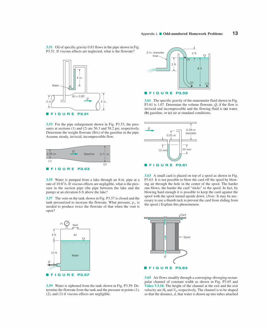
3.37 Air is drawn into a wind tunnel used for testing automo-biles as shown in Fig. P3.37. (a) Determine the manometerreading, h, when the velocity in the test section is 60 mph. Notethat there is a 1-in. column of oil on the water in the manometer.(b) Determine the difference between the stagnation pressure onthe front of the automobile and the pressure in the test section.
3.39 Water (assumed inviscid and incompressible) flowssteadily in the vertical variable-area pipe shown in Fig. P3.39.Determine the flowrate if the pressure in each of the gages reads50 kPa.
3.41 Water flows through the pipe contraction shown in Fig.P3.41. For the given 0.2-m difference in the manometer level,determine the flowrate as a function of the diameter of the smallpipe, D.
3.43 Water flows steadily with negligible viscous effectsthrough the pipe shown in Fig. P3.43. Determine the diame-ter, D, of the pipe at the outlet (a free jet) if the velocity there is20 ft/s.
3.45 Water is siphoned from the tank shown in Fig. P3.45. Thewater barometer indicates a reading of 30.2 ft. Determine themaximum value of h allowed without cavitation occurring. Notethat the pressure of the vapor in the closed end of the barometerequals the vapor pressure.
3.47 An inviscid fluid flows steadily through the contractionshown in Fig. P3.47. Derive an expression for the fluid velocityat (2) in terms of D1, D2, �, �m, and h if the flow is assumed incompressible.
3.49 Carbon dioxide flows at a rate of 1.5 ft3/s from a 3-in. pipein which the pressure and temperature are 20 psi (gage) and 120 F,respectively, into a 1.5-in. pipe. If viscous effects are neglectedand incompressible conditions are assumed, determine the pres-sure in the smaller pipe.
12 Appendix L ■ Odd-numbered Homework Problems
Wind tunnel
Fan
60 mph
h
Water
Open
1 in.
Oil (SG = 0.9)
F I G U R E P3.37
Q
10 m
1 m
2 m
p = 50 kPa
F I G U R E P3.39
0.2 m
Q0.1 m D
F I G U R E P3.41
V = 20 ft/s
D
10 ft15 ft
Open
1.5-in. diameter
F I G U R E P3.43
30.2 ft
6 ft
3 in.diameter
h
Closed end
5-in. diameter
F I G U R E P3.45
h
D2D1
ρQ
Density mρ
F I G U R E P3.47
Appendix L ■ Odd-numbered Homework Problems 13
3.51 Oil of specific gravity 0.83 flows in the pipe shown in Fig.P3.51. If viscous effects are neglected, what is the flowrate?
3.53 For the pipe enlargement shown in Fig. P3.53, the pres-sures at sections (1) and (2) are 56.3 and 58.2 psi, respectively.Determine the weight flowrate (lb/s) of the gasoline in the pipe.Assume steady, inviscid, incompressible flow.
3.55 Water is pumped from a lake through an 8-in. pipe at arate of 10 ft3/s. If viscous effects are negligible, what is the pres-sure in the suction pipe (the pipe between the lake and thepump) at an elevation 6 ft above the lake?
3.57 The vent on the tank shown in Fig. P3.57 is closed and thetank pressurized to increase the flowrate. What pressure, p1, isneeded to produce twice the flowrate of that when the vent isopen?
3.59 Water is siphoned from the tank shown in Fig. P3.59. De-termine the flowrate from the tank and the pressure at points (1),(2), and (3) if viscous effects are negligible.
3.61 The specific gravity of the manometer fluid shown in Fig.P3.61 is 1.07. Determine the volume flowrate, Q, if the flow isinviscid and incompressible and the flowing fluid is (a) water,(b) gasoline, or (c) air at standard conditions.
3.63 A small card is placed on top of a spool as shown in Fig.P3.63. It is not possible to blow the card off the spool by blow-ing air through the hole in the center of the spool. The harderone blows, the harder the card “sticks” to the spool. In fact, byblowing hard enough it is possible to keep the card against thespool with the spool turned upside down. (Note: It may be nec-essary to use a thumb tack to prevent the card from sliding fromthe spool.) Explain this phenomenon.
3.65 Air flows steadily through a converging–diverging rectan-gular channel of constant width as shown in Fig. P3.65 andVideo V3.10. The height of the channel at the exit and the exitvelocity are H0 and V0, respectively. The channel is to be shapedso that the distance, d, that water is drawn up into tubes attached
QGasoline 3.71 in.2.05 in.
(1)(2)
F I G U R E P3.53
Q4 in.3 in.
4 in.
Water
SG = 0.83
F I G U R E P3.51
Water
Air
Vent
4 ft
10 ft
p1
Q
F I G U R E P3.57
2-in.-diameterhose
3 ft
2 ft
8 ft
(2) (1)
(3)
F I G U R E P3.59
Q
0.05 m
10 mm 20 mm
0.09-mdiameter
F I G U R E P3.61
Q
Card
Spool
F I G U R E P3.63
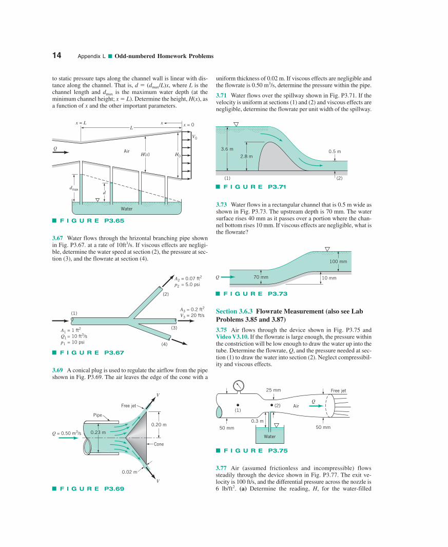
to static pressure taps along the channel wall is linear with dis-tance along the channel. That is, d � (dmax/L)x, where L is thechannel length and dmax is the maximum water depth (at theminimum channel height; x � L). Determine the height, H(x), asa function of x and the other important parameters.
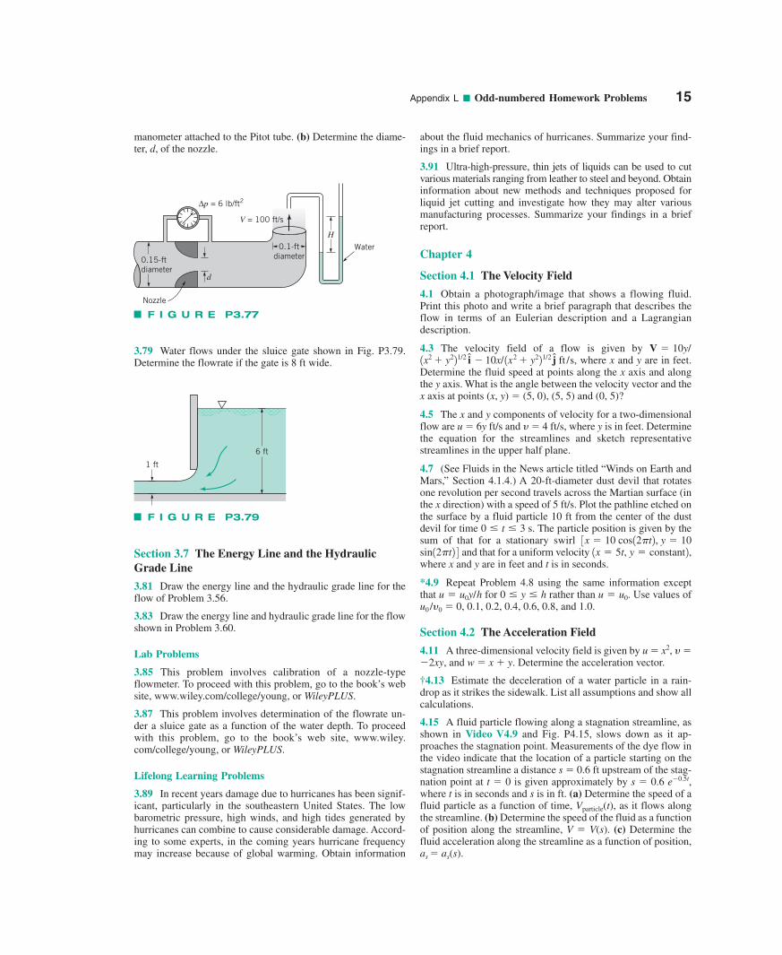
3.67 Water flows through the hrizontal branching pipe shownin Fig. P3.67. at a rate of 10ft3/s. If viscous effects are negligi-ble, determine the water speed at section (2), the pressure at sec-tion (3), and the flowrate at section (4).
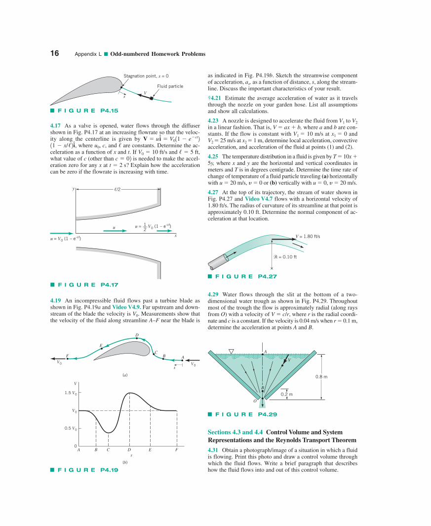
3.69 A conical plug is used to regulate the airflow from the pipeshown in Fig. P3.69. The air leaves the edge of the cone with a
uniform thickness of 0.02 m. If viscous effects are negligible andthe flowrate is 0.50 m3/s, determine the pressure within the pipe.
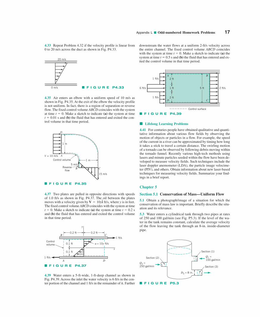
3.71 Water flows over the spillway shown in Fig. P3.71. If thevelocity is uniform at sections (1) and (2) and viscous effects arenegligible, determine the flowrate per unit width of the spillway.
3.73 Water flows in a rectangular channel that is 0.5 m wide asshown in Fig. P3.73. The upstream depth is 70 mm. The watersurface rises 40 mm as it passes over a portion where the chan-nel bottom rises 10 mm. If viscous effects are negligible, what isthe flowrate?
Section 3.6.3 Flowrate Measurement (also see LabProblems 3.85 and 3.87)
3.75 Air flows through the device shown in Fig. P3.75 andVideo V3.10. If the flowrate is large enough, the pressure withinthe constriction will be low enough to draw the water up into thetube. Determine the flowrate, Q, and the pressure needed at sec-tion (1) to draw the water into section (2). Neglect compressibil-ity and viscous effects.
3.77 Air (assumed frictionless and incompressible) flowssteadily through the device shown in Fig. P3.77. The exit ve-locity is 100 ft/s, and the differential pressure across the nozzle is6 lb/ft2. (a) Determine the reading, H, for the water-filled
14 Appendix L ■ Odd-numbered Homework Problems
Water
dmaxd
QAir
H(x) H0
x = 0x = L
V0
Lx
F I G U R E P3.65
(2)
(3)
(4)
(1)
A1 = 1 ft2
Q1 = 10 ft3/sp1 = 10 psi
A2 = 0.07 ft2
p2 = 5.0 psi
A3 = 0.2 ft2
V3 = 20 ft/s
F I G U R E P3.67
F I G U R E P3.69
0.23 mQ = 0.50 m3/s
Pipe
Free jet
0.20 m
V
V
0.02 m
Cone
F I G U R E P3.71
3.6 m
2.8 m
(1) (2)
0.5 m
F I G U R E P3.73
70 mm
100 mm
10 mmQ
F I G U R E P3.75
Air(2)(1)
Q
50 mm 50 mm
25 mm
Water
0.3 m
Free jet
Appendix L ■ Odd-numbered Homework Problems 15
3.79 Water flows under the sluice gate shown in Fig. P3.79.Determine the flowrate if the gate is 8 ft wide.
Section 3.7 The Energy Line and the HydraulicGrade Line
3.81 Draw the energy line and the hydraulic grade line for theflow of Problem 3.56.
3.83 Draw the energy line and hydraulic grade line for the flowshown in Problem 3.60.
Lab Problems
3.85 This problem involves calibration of a nozzle-typeflowmeter. To proceed with this problem, go to the book’s website, www.wiley.com/college/young, or WileyPLUS.
3.87 This problem involves determination of the flowrate un-der a sluice gate as a function of the water depth. To proceedwith this problem, go to the book’s web site, www.wiley.com/college/young, or WileyPLUS.
Lifelong Learning Problems
3.89 In recent years damage due to hurricanes has been signif-icant, particularly in the southeastern United States. The lowbarometric pressure, high winds, and high tides generated byhurricanes can combine to cause considerable damage. Accord-ing to some experts, in the coming years hurricane frequencymay increase because of global warming. Obtain information
about the fluid mechanics of hurricanes. Summarize your find-ings in a brief report.
3.91 Ultra-high-pressure, thin jets of liquids can be used to cutvarious materials ranging from leather to steel and beyond. Obtaininformation about new methods and techniques proposed forliquid jet cutting and investigate how they may alter variousmanufacturing processes. Summarize your findings in a briefreport.
Chapter 4
Section 4.1 The Velocity Field
4.1 Obtain a photograph/image that shows a flowing fluid.Print this photo and write a brief paragraph that describes theflow in terms of an Eulerian description and a Lagrangian description.
4.3 The velocity field of a flow is given by where x and y are in feet.
Determine the fluid speed at points along the x axis and alongthe y axis. What is the angle between the velocity vector and thex axis at points (x, y) � (5, 0), (5, 5) and (0, 5)?
4.5 The x and y components of velocity for a two-dimensionalflow are u � 6y ft/s and y� 4 ft/s, where y is in feet. Determinethe equation for the streamlines and sketch representativestreamlines in the upper half plane.
4.7 (See Fluids in the News article titled “Winds on Earth andMars,” Section 4.1.4.) A 20-ft-diameter dust devil that rotatesone revolution per second travels across the Martian surface (inthe x direction) with a speed of 5 ft/s. Plot the pathline etched onthe surface by a fluid particle 10 ft from the center of the dustdevil for time . The particle position is given by thesum of that for a stationary swirl
and that for a uniform velocity where x and y are in feet and t is in seconds.
*4.9 Repeat Problem 4.8 using the same information exceptthat for rather than Use values ofu0 /y0 � 0, 0.1, 0.2, 0.4, 0.6, 0.8, and 1.0.
Section 4.2 The Acceleration Field
4.11 A three-dimensional velocity field is given by u � x2, y��2xy, and w � x � y. Determine the acceleration vector.
†4.13 Estimate the deceleration of a water particle in a rain-drop as it strikes the sidewalk. List all assumptions and show allcalculations.
4.15 A fluid particle flowing along a stagnation streamline, asshown in Video V4.9 and Fig. P4.15, slows down as it ap-proaches the stagnation point. Measurements of the dye flow inthe video indicate that the location of a particle starting on thestagnation streamline a distance s � 0.6 ft upstream of the stag-nation point at t � 0 is given approximately by s � 0.6 e�0.5t,where t is in seconds and s is in ft. (a) Determine the speed of afluid particle as a function of time, Vparticle(t), as it flows alongthe streamline. (b) Determine the speed of the fluid as a functionof position along the streamline, V � V(s). (c) Determine thefluid acceleration along the streamline as a function of position,as � as(s).
u � u0.0 � y � hu � u0y/h
1x � 5t, y � constant2,sin12�t2 43x � 10 cos12�t2, y � 10
0 � t � 3 s
1x2 � y221/2 i � 10x/ 1x2 � y221/2 j ft /s,V � 10y/
F I G U R E P3.77
Δp = 6 lb/ft2
d
0.15-ftdiameter
0.1-ftdiameter
Water
Nozzle
V = 100 ft/s
H
F I G U R E P3.79
6 ft
1 ft
manometer attached to the Pitot tube. (b) Determine the diame-ter, d, of the nozzle.
4.17 As a valve is opened, water flows through the diffusershown in Fig. P4.17 at an increasing flowrate so that the veloc-ity along the centerline is given by
where c, and are constants. Determine the ac-celeration as a function of x and t. If and what value of c (other than is needed to make the accel-eration zero for any x at Explain how the accelerationcan be zero if the flowrate is increasing with time.
t � 2 s?c � 02
/ � 5 ft,V0 � 10 ft/s/u0,11 � x//2 i,
V � u i � V011 � e�ct2
4.19 An incompressible fluid flows past a turbine blade asshown in Fig. P4.19a and Video V4.9. Far upstream and down-stream of the blade the velocity is V0. Measurements show thatthe velocity of the fluid along streamline A–F near the blade is
as indicated in Fig. P4.19b. Sketch the streamwise componentof acceleration, as, as a function of distance, s, along the stream-line. Discuss the important characteristics of your result.
†4.21 Estimate the average acceleration of water as it travelsthrough the nozzle on your garden hose. List all assumptionsand show all calculations.
4.23 A nozzle is designed to accelerate the fluid from V1 to V2
in a linear fashion. That is, V � ax � b, where a and b are con-stants. If the flow is constant with V1 � 10 m/s at x1 � 0 and V2 � 25 m/s at x2 � 1 m, determine local acceleration, convectiveacceleration, and acceleration of the fluid at points (1) and (2).
4.25 The temperature distribution in a fluid is given by T � 10x �5y, where x and y are the horizontal and vertical coordinates inmeters and T is in degrees centigrade. Determine the time rate ofchange of temperature of a fluid particle traveling (a) horizontallywith u � 20 m/s, y� 0 or (b) vertically with u � 0, y� 20 m/s.
4.27 At the top of its trajectory, the stream of water shown inFig. P4.27 and Video V4.7 flows with a horizontal velocity of1.80 ft/s. The radius of curvature of its streamline at that point isapproximately 0.10 ft. Determine the normal component of ac-celeration at that location.
4.29 Water flows through the slit at the bottom of a two-dimensional water trough as shown in Fig. P4.29. Throughoutmost of the trough the flow is approximately radial (along raysfrom O) with a velocity of V � c/r, where r is the radial coordi-nate and c is a constant. If the velocity is 0.04 m/s when r � 0.1 m,determine the acceleration at points A and B.
Sections 4.3 and 4.4 Control Volume and SystemRepresentations and the Reynolds Transport Theorem
4.31 Obtain a photograph/image of a situation in which a fluidis flowing. Print this photo and draw a control volume throughwhich the fluid flows. Write a brief paragraph that describeshow the fluid flows into and out of this control volume.
16 Appendix L ■ Odd-numbered Homework Problems
Stagnation point, s = 0
Fluid particle
Vs
F I G U R E P4.15
u = V0 (1 – e-ct)
u = V0 (1 – e-ct)
�/2
12u
y
x
F I G U R E P4.17
(a)
(b)
E
F
D
CB A
V0V0
V
1.5 V0
0A B C D E F
s
V0
0.5 V0
s
F I G U R E P4.19
� = 0.10 ft
V = 1.80 ft/s
F I G U R E P4.27
0.8 m
O
A
V
B
0.2 m
F I G U R E P4.29
Appendix L ■ Odd-numbered Homework Problems 17
4.33 Repeat Problem 4.32 if the velocity profile is linear from0 to 20 m/s across the duct as shown in Fig. P4.33.
4.35 Air enters an elbow with a uniform speed of 10 m/s asshown in Fig. P4.35. At the exit of the elbow the velocity profileis not uniform. In fact, there is a region of separation or reverseflow. The fixed control volume ABCD coincides with the systemat time t � 0. Make a sketch to indicate (a) the system at time t � 0.01 s and (b) the fluid that has entered and exited the con-trol volume in that time period.
4.37 Two plates are pulled in opposite directions with speedsof 1.0 ft/s as shown in Fig. P4.37. The oil between the platesmoves with a velocity given by where y is in feet.The fixed control volume ABCD coincides with the system at timet � 0. Make a sketch to indicate (a) the system at time t � 0.2 sand (b) the fluid that has entered and exited the control volumein that time period.
V � 10yi ft/s,
4.39 Water enters a 5-ft-wide, 1-ft-deep channel as shown inFig. P4.39. Across the inlet the water velocity is 6 ft/s in the cen-ter portion of the channel and 1 ft/s in the remainder of it. Farther
■ Lifelong Learning Problems
4.41 For centuries people have obtained qualitative and quanti-tative information about various flow fields by observing themotion of objects or particles in a flow. For example, the speedof the current in a river can be approximated by timing how longit takes a stick to travel a certain distance. The swirling motionof a tornado can be observed by following debris moving withinthe tornado funnel. Recently various high-tech methods usinglasers and minute particles seeded within the flow have been de-veloped to measure velocity fields. Such techniques include thelaser doppler anemometer (LDA), the particle image velocime-ter (PIV), and others. Obtain information about new laser-basedtechniques for measuring velocity fields. Summarize your find-ings in a brief report.
Chapter 5
Section 5.1 Conservation of Mass—Uniform Flow
5.1 Obtain a photograph/image of a situation for which theconservation of mass law is important. Briefly describe the situ-ation and its relevance.
5.3 Water enters a cylindrical tank through two pipes at ratesof 250 and 100 gal/min (see Fig. P5.3). If the level of the wa-ter in the tank remains constant, calculate the average velocityof the flow leaving the tank through an 8-in. inside-diameterpipe.
20 m/s
0 m/s F I G U R E P4.33
F I G U R E P4.35
1 m
1 m
5 m/s
15 m/s
V = 10 m/sControl volume
Reverseflow
B C
A
D
F I G U R E P4.37
y
x
1 ft/s
0.2 ft 0.2 ftCB
A D
0.1 ft
0.1 ft
Controlvolume
1 ft/s
u = 10y ft/s
1 ft/s
2 ft/s
1 ft/s
6 ft/s
Control surface
A
D
B
C2 ft
2 ft
1 ft 5 ft
F I G U R E P4.39
downstream the water flows at a uniform 2-ft/s velocity acrossthe entire channel. The fixed control volume ABCD coincideswith the system at time t � 0. Make a sketch to indicate (a) thesystem at time t � 0.5 s and (b) the fluid that has entered and ex-ited the control volume in that time period.
Section (1)
Section (3)
Section (2)
Q2 = 250 gal/min
Q1 = 100 gal/min
D3 = 8 in.
F I G U R E P5.3
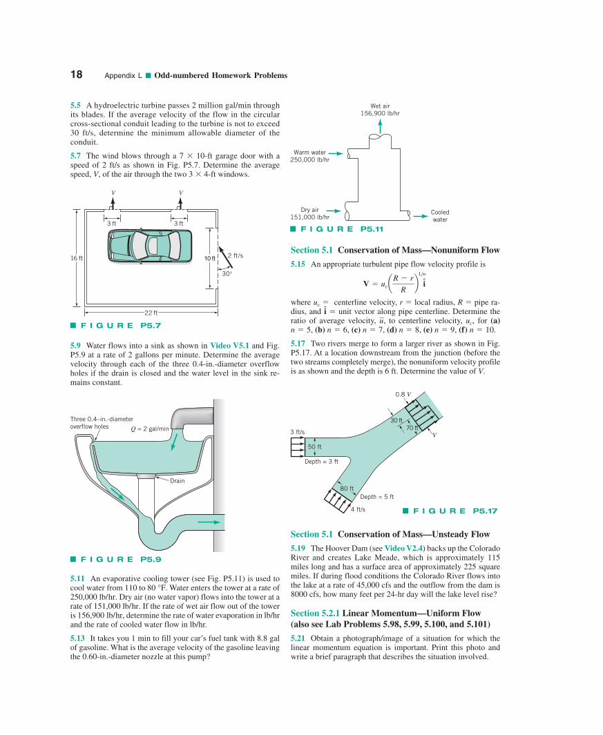
5.5 A hydroelectric turbine passes 2 million gal/min throughits blades. If the average velocity of the flow in the circularcross-sectional conduit leading to the turbine is not to exceed30 ft/s, determine the minimum allowable diameter of theconduit.
5.7 The wind blows through a 7 10-ft garage door with aspeed of 2 ft/s as shown in Fig. P5.7. Determine the averagespeed, V, of the air through the two 3 4-ft windows.
5.9 Water flows into a sink as shown in Video V5.1 and Fig.P5.9 at a rate of 2 gallons per minute. Determine the averagevelocity through each of the three 0.4-in.-diameter overflowholes if the drain is closed and the water level in the sink re-mains constant.
5.11 An evaporative cooling tower (see Fig. P5.11) is used tocool water from 110 to . Water enters the tower at a rate of
. Dry air (no water vapor) flows into the tower at arate of . If the rate of wet air flow out of the toweris , determine the rate of water evaporation in lb/hrand the rate of cooled water flow in lb/hr.
5.13 It takes you 1 min to fill your car’s fuel tank with 8.8 galof gasoline. What is the average velocity of the gasoline leavingthe 0.60-in.-diameter nozzle at this pump?
156,900 lb/hr151,000 lb/hr
250,000 lb/hr80 °F
Section 5.1 Conservation of Mass—Nonuniform Flow
5.15 An appropriate turbulent pipe flow velocity profile is
where centerline velocity, r � local radius, R � pipe ra-dius, and unit vector along pipe centerline. Determine theratio of average velocity, to centerline velocity, for (a)
(b) (c) (d) (e) (f)
5.17 Two rivers merge to form a larger river as shown in Fig.P5.17. At a location downstream from the junction (before thetwo streams completely merge), the nonuniform velocity profileis as shown and the depth is 6 ft. Determine the value of V.
n � 10.n � 9,n � 8,n � 7,n � 6,n � 5,uc,u,
i �uc �
V � uc aR � r
Rb
1�n
i
Section 5.1 Conservation of Mass—Unsteady Flow
5.19 The Hoover Dam (see Video V2.4) backs up the ColoradoRiver and creates Lake Meade, which is approximately 115miles long and has a surface area of approximately 225 squaremiles. If during flood conditions the Colorado River flows intothe lake at a rate of 45,000 cfs and the outflow from the dam is8000 cfs, how many feet per 24-hr day will the lake level rise?
Section 5.2.1 Linear Momentum—Uniform Flow(also see Lab Problems 5.98, 5.99, 5.100, and 5.101)
5.21 Obtain a photograph/image of a situation for which thelinear momentum equation is important. Print this photo andwrite a brief paragraph that describes the situation involved.
18 Appendix L ■ Odd-numbered Homework Problems
10 ft16 ft
22 ft
3 ft 3 ft
V V
2 ft /s
30°
F I G U R E P5.7
Three 0.4–in.-diameteroverflow holes Q = 2 gal/min
Drain
F I G U R E P5.9
Warm water 250,000 lb/hr
Wet air 156,900 lb/hr
Dry air 151,000 lb/hr
Cooled water
F I G U R E P5.11
4 ft/s
3 ft/s
Depth = 3 ft
Depth = 5 ft80 ft
50 ft
0.8 V
V70 ft
30 ft
F I G U R E P5.17
Appendix L ■ Odd-numbered Homework Problems 19
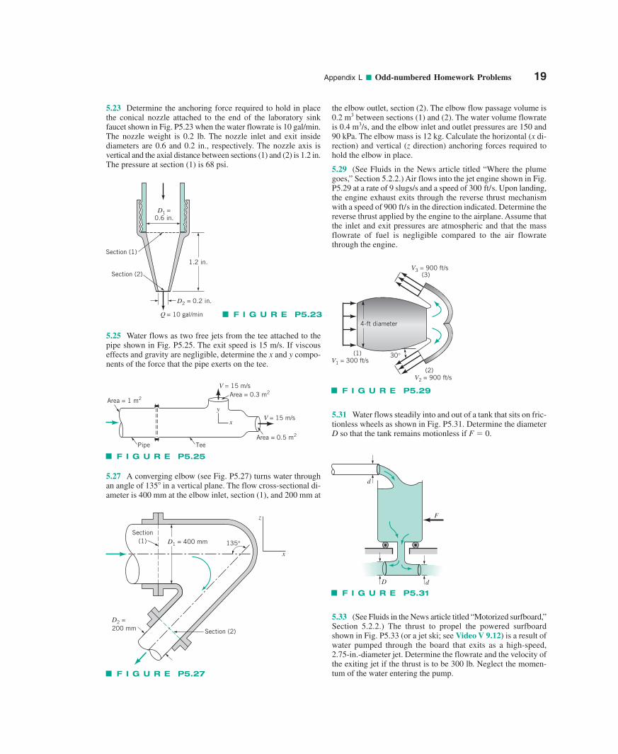
5.23 Determine the anchoring force required to hold in placethe conical nozzle attached to the end of the laboratory sinkfaucet shown in Fig. P5.23 when the water flowrate is 10 gal/min.The nozzle weight is 0.2 lb. The nozzle inlet and exit inside diameters are 0.6 and 0.2 in., respectively. The nozzle axis isvertical and the axial distance between sections (1) and (2) is 1.2 in.The pressure at section (1) is 68 psi.
5.25 Water flows as two free jets from the tee attached to thepipe shown in Fig. P5.25. The exit speed is 15 m/s. If viscous effects and gravity are negligible, determine the x and y compo-nents of the force that the pipe exerts on the tee.
5.27 A converging elbow (see Fig. P5.27) turns water throughan angle of 135 in a vertical plane. The flow cross-sectional di-ameter is 400 mm at the elbow inlet, section (1), and 200 mm at
the elbow outlet, section (2). The elbow flow passage volume is0.2 m3 between sections (1) and (2). The water volume flowrateis 0.4 m3/s, and the elbow inlet and outlet pressures are 150 and90 kPa. The elbow mass is 12 kg. Calculate the horizontal (x di-rection) and vertical (z direction) anchoring forces required tohold the elbow in place.
5.29 (See Fluids in the News article titled “Where the plumegoes,” Section 5.2.2.) Air flows into the jet engine shown in Fig.P5.29 at a rate of 9 slugs/s and a speed of . Upon landing,the engine exhaust exits through the reverse thrust mechanismwith a speed of in the direction indicated. Determine thereverse thrust applied by the engine to the airplane. Assume thatthe inlet and exit pressures are atmospheric and that the massflowrate of fuel is negligible compared to the air flowratethrough the engine.
900 ft/s
300 ft/s
5.31 Water flows steadily into and out of a tank that sits on fric-tionless wheels as shown in Fig. P5.31. Determine the diameterD so that the tank remains motionless if F � 0.
5.33 (See Fluids in the News article titled “Motorized surfboard,”Section 5.2.2.) The thrust to propel the powered surfboardshown in Fig. P5.33 (or a jet ski; see Video V 9.12) is a result ofwater pumped through the board that exits as a high-speed,2.75-in.-diameter jet. Determine the flowrate and the velocity ofthe exiting jet if the thrust is to be 300 lb. Neglect the momen-tum of the water entering the pump.
D1 =0.6 in.
Q = 10 gal/min
1.2 in.
Section (2)
Section (1)
D2 = 0.2 in.
F I G U R E P5.23
V1 = 300 ft/s(1)
V3 = 900 ft/s(3)
(2)V2 = 900 ft/s
4-ft diameter
30°
F I G U R E P5.29
F
D d
d
F I G U R E P5.31
y
x
V = 15 m/s
V = 15 m/s
Area = 0.3 m2
Area = 0.5 m2
Area = 1 m2
TeePipe
F I G U R E P5.25
D2 =200 mm Section (2)
z
x
D1 = 400 mmSection
(1) 135°
F I G U R E P5.27
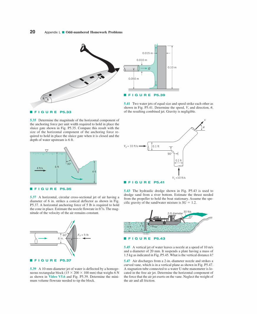
5.35 Determine the magnitude of the horizontal component ofthe anchoring force per unit width required to hold in place thesluice gate shown in Fig. P5.35. Compare this result with thesize of the horizontal component of the anchoring force re-quired to hold in place the sluice gate when it is closed and thedepth of water upstream is 6 ft.
5.37 A horizontal, circular cross-sectional jet of air having adiameter of 6 in. strikes a conical deflector as shown in Fig.P5.37. A horizontal anchoring force of 5 lb is required to holdthe cone in place. Estimate the nozzle flowrate in ft3/s. The mag-nitude of the velocity of the air remains constant.
5.39 A 10-mm-diameter jet of water is deflected by a homoge-neous rectangular block (15 200 100 mm) that weighs 6 Nas shown in Video V5.6 and Fig. P5.39. Determine the mini-mum volume flowrate needed to tip the block.
5.41 Two water jets of equal size and speed strike each other asshown in Fig. P5.41. Determine the speed, V, and direction, �,of the resulting combined jet. Gravity is negligible.
5.43 The hydraulic dredge shown in Fig. P5.43 is used todredge sand from a river bottom. Estimate the thrust neededfrom the propeller to hold the boat stationary. Assume the spe-cific gravity of the sand/water mixture is SG � 1.2.
5.45 A vertical jet of water leaves a nozzle at a speed of 10 m/sand a diameter of 20 mm. It suspends a plate having a mass of1.5 kg as indicated in Fig. P5.45. What is the vertical distance h?
5.47 Air discharges from a 2-in.-diameter nozzle and strikes acurved vane, which is in a vertical plane as shown in Fig. P5.47.A stagnation tube connected to a water U-tube manometer is lo-cated in the free air jet. Determine the horizontal component ofthe force that the air jet exerts on the vane. Neglect the weight ofthe air and all friction.
20 Appendix L ■ Odd-numbered Homework Problems
F I G U R E P5.33
0.050 m
0.010 m
0.10 m
0.015 m
Q
F I G U R E P5.39
90°
V 1 =10 ft /s
V2 = 10 ft /s
V
0.1 ft
0.1 ft
θ
F I G U R E P5.41
2-ft diameter30°
30 ft/s
9 ft 7 ft Prop
F I G U R E P5.43
6 ft30°
4 ft4 ft/s
F I G U R E P5.35
6 in.60° FA = 5 lb
F I G U R E P5.37
Appendix L ■ Odd-numbered Homework Problems 21
Section 5.2.1 Linear Momentum—Nonuniform Flow
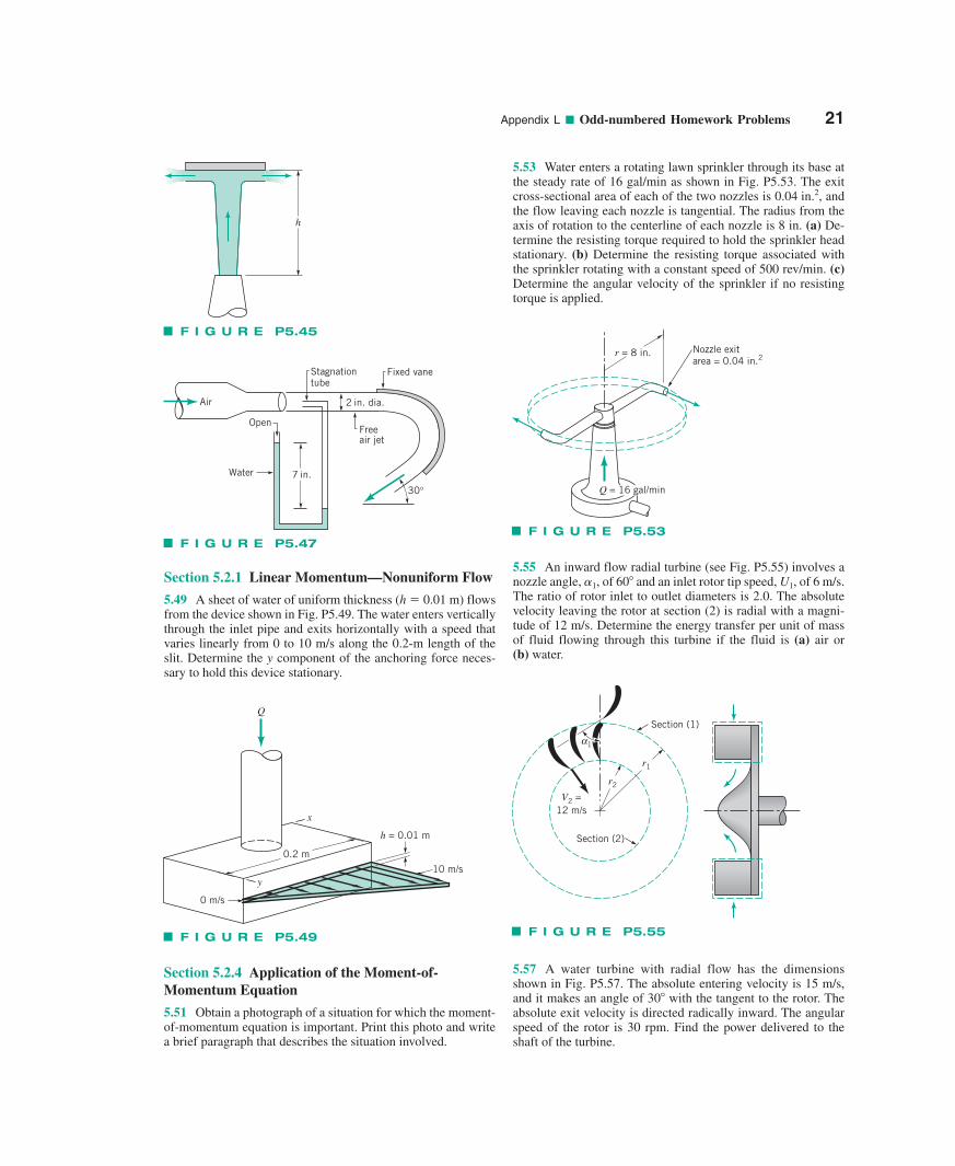
5.49 A sheet of water of uniform thickness (h � 0.01 m) flowsfrom the device shown in Fig. P5.49. The water enters verticallythrough the inlet pipe and exits horizontally with a speed thatvaries linearly from 0 to 10 m/s along the 0.2-m length of theslit. Determine the y component of the anchoring force neces-sary to hold this device stationary.
Section 5.2.4 Application of the Moment-of-Momentum Equation
5.51 Obtain a photograph of a situation for which the moment-of-momentum equation is important. Print this photo and writea brief paragraph that describes the situation involved.
5.53 Water enters a rotating lawn sprinkler through its base atthe steady rate of 16 gal/min as shown in Fig. P5.53. The exitcross-sectional area of each of the two nozzles is andthe flow leaving each nozzle is tangential. The radius from theaxis of rotation to the centerline of each nozzle is 8 in. (a) De-termine the resisting torque required to hold the sprinkler headstationary. (b) Determine the resisting torque associated withthe sprinkler rotating with a constant speed of 500 rev/min. (c)Determine the angular velocity of the sprinkler if no resistingtorque is applied.
0.04 in.2,
5.55 An inward flow radial turbine (see Fig. P5.55) involves anozzle angle, 1, of 60 and an inlet rotor tip speed, U1, of 6 m/s.The ratio of rotor inlet to outlet diameters is 2.0. The absolutevelocity leaving the rotor at section (2) is radial with a magni-tude of 12 m/s. Determine the energy transfer per unit of massof fluid flowing through this turbine if the fluid is (a) air or (b) water.
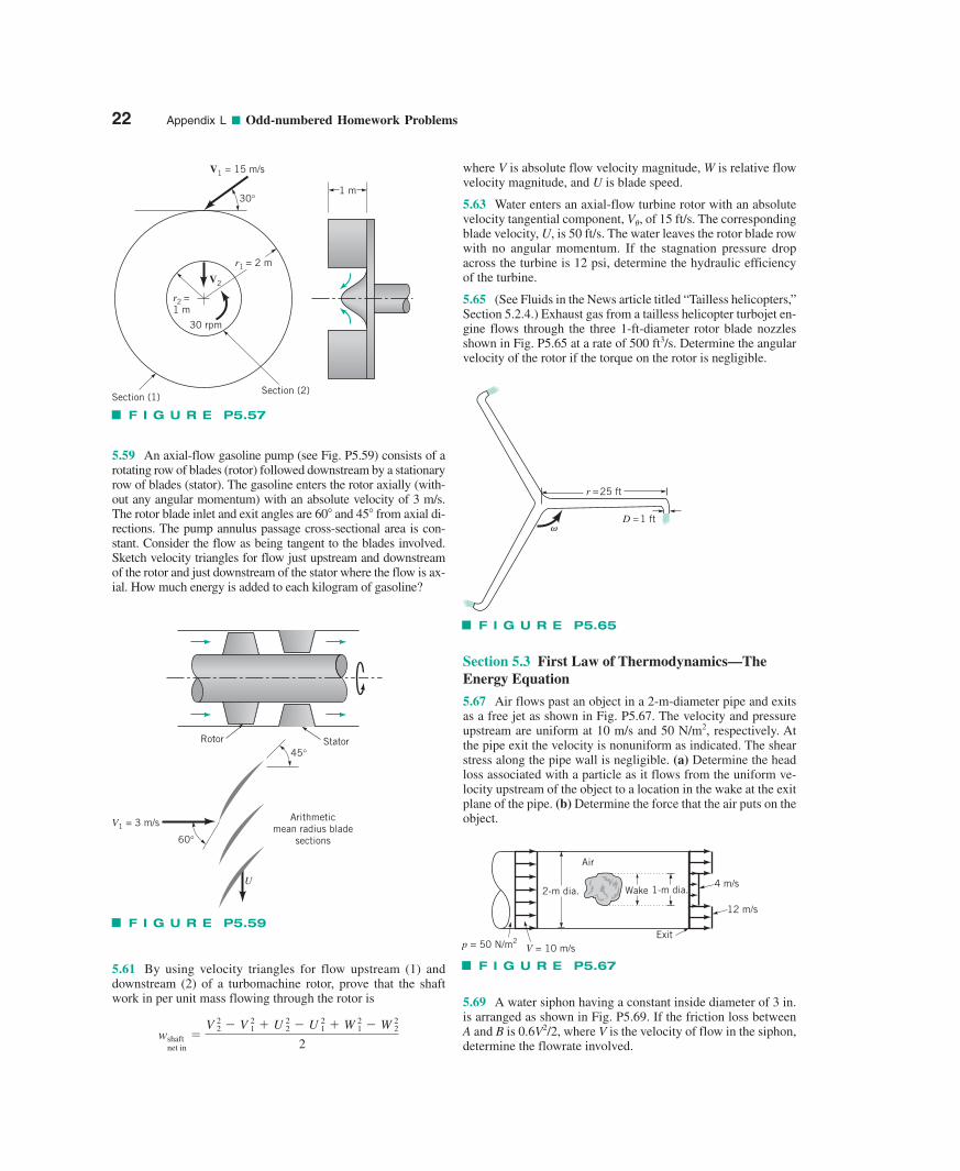
5.57 A water turbine with radial flow has the dimensionsshown in Fig. P5.57. The absolute entering velocity is 15 m/s,and it makes an angle of 30 with the tangent to the rotor. Theabsolute exit velocity is directed radically inward. The angularspeed of the rotor is 30 rpm. Find the power delivered to theshaft of the turbine.
h
F I G U R E P5.45
7 in.
Fixed vane
2 in. dia.
Freeair jet
Stagnationtube
Air
Water
Open
30°
F I G U R E P5.47
0.2 m
h = 0.01 m
x
y
0 m/s
10 m/s
Q
F I G U R E P5.49
Q = 16 gal/min
r = 8 in. Nozzle exitarea = 0.04 in.2
F I G U R E P5.53
V2 =12 m/s
r2
r1
Section (2)
Section (1)
α1
F I G U R E P5.55
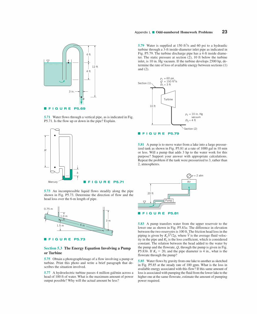
5.59 An axial-flow gasoline pump (see Fig. P5.59) consists of arotating row of blades (rotor) followed downstream by a stationaryrow of blades (stator). The gasoline enters the rotor axially (with-out any angular momentum) with an absolute velocity of 3 m/s.The rotor blade inlet and exit angles are 60 and 45 from axial di-rections. The pump annulus passage cross-sectional area is con-stant. Consider the flow as being tangent to the blades involved.Sketch velocity triangles for flow just upstream and downstreamof the rotor and just downstream of the stator where the flow is ax-ial. How much energy is added to each kilogram of gasoline?
5.61 By using velocity triangles for flow upstream (1) anddownstream (2) of a turbomachine rotor, prove that the shaftwork in per unit mass flowing through the rotor is
wshaftnet in
�V 22 � V 21 � U 22 � U 21 � W 21 � W 22
2
where V is absolute flow velocity magnitude, W is relative flowvelocity magnitude, and U is blade speed.
5.63 Water enters an axial-flow turbine rotor with an absolutevelocity tangential component, V�, of 15 ft/s. The correspondingblade velocity, U, is 50 ft/s. The water leaves the rotor blade rowwith no angular momentum. If the stagnation pressure dropacross the turbine is 12 psi, determine the hydraulic efficiencyof the turbine.
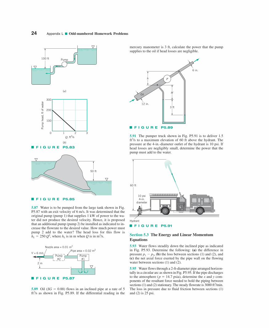
5.65 (See Fluids in the News article titled “Tailless helicopters,”Section 5.2.4.) Exhaust gas from a tailless helicopter turbojet en-gine flows through the three 1-ft-diameter rotor blade nozzlesshown in Fig. P5.65 at a rate of 500 ft3/s. Determine the angularvelocity of the rotor if the torque on the rotor is negligible.
Section 5.3 First Law of Thermodynamics—TheEnergy Equation
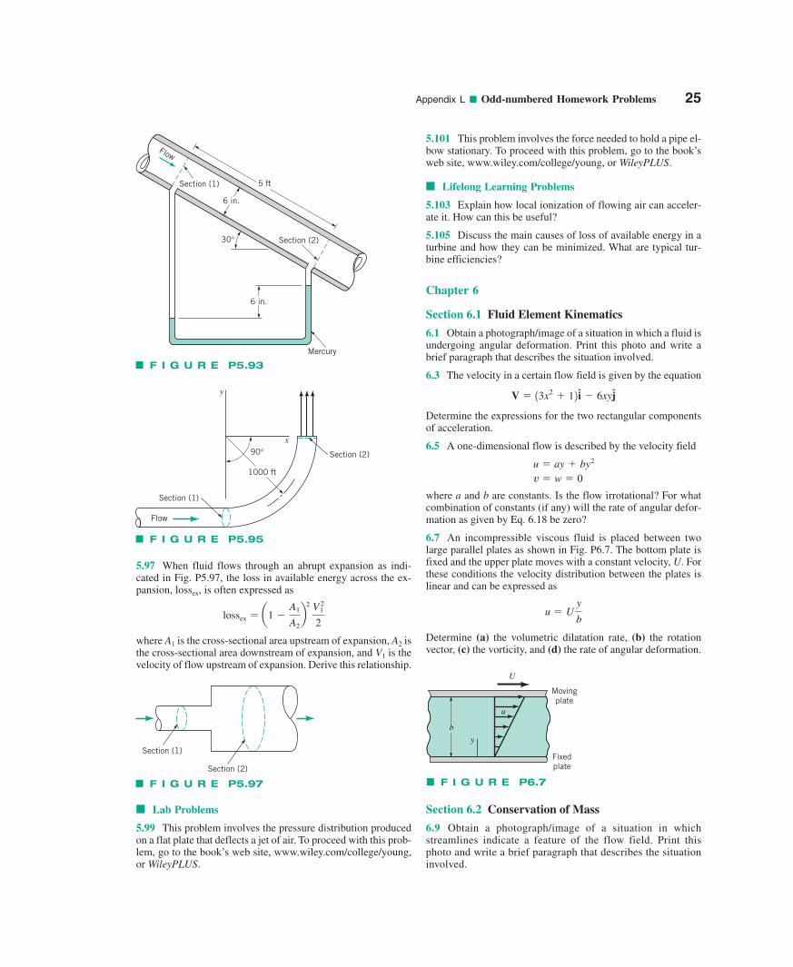
5.67 Air flows past an object in a 2-m-diameter pipe and exitsas a free jet as shown in Fig. P5.67. The velocity and pressureupstream are uniform at 10 m/s and 50 N/m2, respectively. Atthe pipe exit the velocity is nonuniform as indicated. The shearstress along the pipe wall is negligible. (a) Determine the headloss associated with a particle as it flows from the uniform ve-locity upstream of the object to a location in the wake at the exitplane of the pipe. (b) Determine the force that the air puts on theobject.
5.69 A water siphon having a constant inside diameter of 3 in.is arranged as shown in Fig. P5.69. If the friction loss betweenA and B is 0.6V2/2, where V is the velocity of flow in the siphon,determine the flowrate involved.
22 Appendix L ■ Odd-numbered Homework Problems
V2
30 rpm
V1 = 15 m/s
Section (2)Section (1)
r2 = 1 m
1 m30°
r1 = 2 m
F I G U R E P5.57
r =25 ft
�D =1 ft
F I G U R E P5.65
2-m dia. 1-m dia.4 m/s
12 m/s
Exit
Wake
Air
p = 50 N/m2V = 10 m/s
F I G U R E P5.67
U
V1 = 3 m/s
60°
45°
Arithmeticmean radius blade
sections
Rotor Stator
F I G U R E P5.59
Appendix L ■ Odd-numbered Homework Problems 23
5.71 Water flows through a vertical pipe, as is indicated in Fig.P5.71. Is the flow up or down in the pipe? Explain.
5.73 An incompressible liquid flows steadily along the pipeshown in Fig. P5.73. Determine the direction of flow and thehead loss over the 6-m length of pipe.
Section 5.3 The Energy Equation Involving a Pumpor Turbine
5.75 Obtain a photograph/image of a flow involving a pump orturbine. Print this photo and write a brief paragraph that de-scribes the situation involved.
5.77 A hydroelectric turbine passes 4 million gal/min across ahead of 100 ft of water. What is the maximum amount of poweroutput possible? Why will the actual amount be less?
5.79 Water is supplied at 150 ft3/s and 60 psi to a hydraulicturbine through a 3-ft inside-diameter inlet pipe as indicated inFig. P5.79. The turbine discharge pipe has a 4-ft inside diame-ter. The static pressure at section (2), 10 ft below the turbine inlet, is 10 in. Hg vacuum. If the turbine develops 2500 hp, de-termine the rate of loss of available energy between sections (1)and (2).
5.81 A pump is to move water from a lake into a large pressur-ized tank as shown in Fig. P5.81 at a rate of 1000 gal in 10 minor less. Will a pump that adds 3 hp to the water work for thispurpose? Support your answer with appropriate calculations.Repeat the problem if the tank were pressurized to 3, rather than2, atmospheres.
5.83 A pump transfers water from the upper reservoir to thelower one as shown in Fig. P5.83a. The difference in elevationbetween the two reservoirs is 100 ft. The friction head loss in thepiping is given by , where is the average fluid veloc-ity in the pipe and KL is the loss coefficient, which is consideredconstant. The relation between the head added to the water bythe pump and the flowrate, Q, through the pump is given in Fig.P5.83b. If KL � 20, and the pipe diameter is 4 in., what is theflowrate through the pump?
5.85 Water flows by gravity from one lake to another as sketchedin Fig. P5.85 at the steady rate of 100 gpm. What is the loss inavailable energy associated with this flow? If this same amount ofloss is associated with pumping the fluid from the lower lake to thehigher one at the same flowrate, estimate the amount of pumpingpower required.
VKLV2/2g
A
4 ft
4 ft
12 ft
3 in.
B
F I G U R E P5.69
Turbine
10 ft
Section (1)
p1QD1
= 60 psi= 150 ft3/s= 3 ft
p2
D2
= 10 in. Hg vacuum= 4 ft
Section (2)
F I G U R E P5.79
20 ft
Air
Pump
p = 2 atm
F I G U R E P5.81
H
h
Mercury F I G U R E P5.71
0.75 m
1.0 m
1.5 m 6 m
3 m
F I G U R E P5.73
5.87 Water is to be pumped from the large tank shown in Fig.P5.87 with an exit velocity of . It was determined that theoriginal pump (pump 1) that supplies 1 kW of power to the wa-ter did not produce the desired velocity. Hence, it is proposedthat an additional pump (pump 2) be installed as indicated to in-crease the flowrate to the desired value. How much power mustpump 2 add to the water? The head loss for this flow is
where is in m when Q is in m3/s.hLhL � 250 Q2,
6 m/s
5.89 Oil (SG � 0.88) flows in an inclined pipe at a rate of 5ft3/s as shown in Fig. P5.89. If the differential reading in the
mercury manometer is 3 ft, calculate the power that the pumpsupplies to the oil if head losses are negligible.
5.91 The pumper truck shown in Fig. P5.91 is to deliver 1.5ft3/s to a maximum elevation of 60 ft above the hydrant. Thepressure at the 4-in.-diameter outlet of the hydrant is 10 psi. Ifhead losses are negligibly small, determine the power that thepump must add to the water.
Section 5.3 The Energy and Linear MomentumEquations
5.93 Water flows steadily down the inclined pipe as indicatedin Fig. P5.93. Determine the following: (a) the difference inpressure p1 � p2, (b) the loss between sections (1) and (2), and(c) the net axial force exerted by the pipe wall on the flowingwater between sections (1) and (2).
5.95 Water flows through a 2-ft-diameter pipe arranged horizon-tally in a circular arc as shown in Fig. P5.95. If the pipe dischargesto the atmosphere (p � 14.7 psia), determine the x and y com-ponents of the resultant force needed to hold the piping betweensections (1) and (2) stationary. The steady flowrate is 3000 ft3/min.The loss in pressure due to fluid friction between sections (1)and (2) is 25 psi.
24 Appendix L ■ Odd-numbered Homework Problems
100 ft Pump
(a)
200
100
0 1 2Q, ft3/s
Pum
p he
ad, ft
of
wat
er
(b)
300
3
F I G U R E P5.83
50 ft
F I G U R E P5.85
H
Ph
3 ft
Oil
12 in.
6 in.
F I G U R E P5.89
Hydrant
60 ft
10 psi4-in.
diameter
F I G U R E P5.91
V = 6 m/sPump
#2
Pipe area = 0.02 m2Nozzle area = 0.01 m2
2 m
Pump#1
F I G U R E P5.87
Appendix L ■ Odd-numbered Homework Problems 25
5.97 When fluid flows through an abrupt expansion as indi-cated in Fig. P5.97, the loss in available energy across the ex-pansion, lossex, is often expressed as
where A1 is the cross-sectional area upstream of expansion, A2 isthe cross-sectional area downstream of expansion, and V1 is thevelocity of flow upstream of expansion. Derive this relationship.
lossex � a1 �A1
A2b
2 V 21
2
■ Lab Problems
5.99 This problem involves the pressure distribution producedon a flat plate that deflects a jet of air. To proceed with this prob-lem, go to the book’s web site, www.wiley.com/college/young,or WileyPLUS.
5.101 This problem involves the force needed to hold a pipe el-bow stationary. To proceed with this problem, go to the book’sweb site, www.wiley.com/college/young, or WileyPLUS.
■ Lifelong Learning Problems
5.103 Explain how local ionization of flowing air can acceler-ate it. How can this be useful?
5.105 Discuss the main causes of loss of available energy in aturbine and how they can be minimized. What are typical tur-bine efficiencies?
Chapter 6
Section 6.1 Fluid Element Kinematics
6.1 Obtain a photograph/image of a situation in which a fluid isundergoing angular deformation. Print this photo and write abrief paragraph that describes the situation involved.
6.3 The velocity in a certain flow field is given by the equation
Determine the expressions for the two rectangular componentsof acceleration.
6.5 A one-dimensional flow is described by the velocity field
where a and b are constants. Is the flow irrotational? For whatcombination of constants (if any) will the rate of angular defor-mation as given by Eq. 6.18 be zero?
6.7 An incompressible viscous fluid is placed between twolarge parallel plates as shown in Fig. P6.7. The bottom plate isfixed and the upper plate moves with a constant velocity, U. Forthese conditions the velocity distribution between the plates islinear and can be expressed as
Determine (a) the volumetric dilatation rate, (b) the rotationvector, (c) the vorticity, and (d) the rate of angular deformation.
u � Uy
b
v � w � 0 u � ay � by2
V � 13x2 � 12 i � 6xyj
5 ft
6 in.
30°
Mercury
Section (2)
Section (1)
Flow
6 in.
F I G U R E P5.93
y
x
Section (2)90°
Section (1)
Flow
1000 ft
F I G U R E P5.95
Section (1)
Section (2)
F I G U R E P5.97
U
b
y
u
Fixedplate
Movingplate
F I G U R E P6.7
Section 6.2 Conservation of Mass
6.9 Obtain a photograph/image of a situation in whichstreamlines indicate a feature of the flow field. Print thisphoto and write a brief paragraph that describes the situationinvolved.
6.11 The radial velocity component in an incompressible, two-dimensional flow field (z � 0) is
Determine the corresponding tangential velocity component, y�,required to satisfy conservation of mass.
6.13 The velocity components of an incompressible, two-dimensional velocity field are given by the equations
Show that the flow is irrotational and satisfies conservation ofmass.
6.15 For each of the following stream functions, with units ofm2/s, determine the magnitude and the angle the velocity vectormakes with the x axis at x � 1 m, y � 2 m. Locate any stagna-tion points in the flow field.
(a)(b)
6.17 For a certain incompressible flow field it is suggested thatthe velocity components are given by the equations
Is this a physically possible flow field? Explain.
6.19 The streamlines in a certain incompressible, two-dimensionalflow field are all concentric circles so that Determine thestream function for (a) and for (b) where Ais a constant.
6.21 The velocity components in an incompressible, two-dimensional flow field are given by the equations.
Determine, if possible, the corresponding stream function.
6.23 The stream function for an incompressible flow field isgiven by the equation
where the stream function has the units of m2/s with x and y inmeters. (a) Sketch the streamline(s) passing through the origin.(b) Determine the rate of flow across the straight path AB shownin Fig. P6.23.
� � 3x2y � y3
v � �2xy � x
u � x2
y� � Ar�1,y� � Aryr � 0.
u � 2xy v � �x2y w � 0
c � �2x2 � yc � xy
v � y12x � 12 u � y2 � x11 � x2
yr � 2r � 3r 2 sin �
Section 6.4 Inviscid Flow
6.25 The stream function for a given two-dimensional flowfield is
Determine the corresponding velocity potential.
6.27 The streamlines for an incompressible, inviscid, two-dimensional flow field are all concentric circles, and the velocityvaries directly with the distance from the common center of thestreamlines; that is
where K is a constant. (a) For this rotational flow, determine, ifpossible, the stream function. (b) Can the pressure differencebetween the origin and any other point be determined from theBernoulli equation? Explain.
6.29 A certain flow field is described by the stream function
where A and B are positive constants. Determine the corre-sponding velocity potential and locate any stagnation points inthis flow field.
6.31 The velocity potential for a certain inviscid, incompress-ible flow field is given by the equation
where � has the units of m2/s when x and y are in meters. Deter-mine the pressure at the point x � 2 m, y � 2 m if the pressure atx � 1 m, y � 1 m is 200 kPa. Elevation changes can be neglectedand the fluid is water.
6.33 An ideal fluid flows between the inclined walls of a two-dimensional channel into a sink located at the origin (Fig.P6.33). The velocity potential for this flow field is
where m is a constant. (a) Determine the corresponding streamfunction. Note that the value of the stream function along thewall OA is zero. (b) Determine the equation of the streamlinepassing through the point B, located at x � 1, y � 4.
f �m
2p ln r
f � 2x2y � 123 2y3
c � A u � B r sin u
y� � Kr
� � 5x2y � 15/32y3
26 Appendix L ■ Odd-numbered Homework Problems
y, m
x, m1.0
1.0 B
A
0
F I G U R E P6.23
B (1, 4)
Aψ = 0
θπ__3
y
xO
r
F I G U R E P6.33
Section 6.5 Some Basic, Plane Potential Flows
6.35 Water flows through a two-dimensional diffuser having a 20expansion angle as shown in Fig. P6.35. Assume that the flow in thediffuser can be treated as a radial flow emanating from a source at
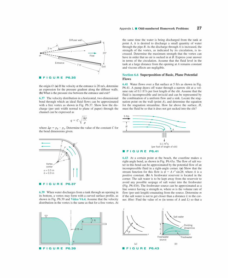
Appendix L ■ Odd-numbered Homework Problems 27
the origin O. (a) If the velocity at the entrance is 20 m/s, determinean expression for the pressure gradient along the diffuser walls. (b) What is the pressure rise between the entrance and exit?
6.37 The velocity distribution in a horizontal, two-dimensionalbend through which an ideal fluid flows can be approximatedwith a free vortex as shown in Fig. P6.37. Show how the dis-charge (per unit width normal to plane of paper) through thechannel can be expressed as
where �p � pB � pA. Determine the value of the constant C forthe bend dimensions given.
q � C B¢p
�
the same time the water is being discharged from the tank atpoint A, it is desired to discharge a small quantity of waterthrough the pipe B. As the discharge through A is increased, thestrength of the vortex, as indicated by its circulation, is in-creased. Determine the maximum strength that the vortex canhave in order that no air is sucked in at B. Express your answerin terms of the circulation. Assume that the fluid level in thetank at a large distance from the opening at A remains constantand viscous effects are negligible.
Section 6.6 Superposition of Basic, Plane PotentialFlows
6.41 Water flows over a flat surface at 5 ft/s as shown in Fig.P6.41. A pump draws off water through a narrow slit at a vol-ume rate of 0.1 ft3/s per foot length of the slit. Assume that thefluid is incompressible and inviscid and can be represented bythe combination of a uniform flow and a sink. Locate the stag-nation point on the wall (point A), and determine the equationfor the stagnation streamline. How far above the surface, H,must the fluid be so that it does not get sucked into the slit?
6.43 At a certain point at the beach, the coastline makes aright-angle bend, as shown in Fig. P6.43a. The flow of salt wa-ter in this bend can be approximated by the potential flow of anincompressible fluid in a right-angle corner. (a) Show that thestream function for this flow is where A is apositive constant. (b) A freshwater reservoir is located in thecorner. The salt water is to be kept away from the reservoir toavoid any possible seepage of salt water into the freshwater(Fig. P6.43b). The freshwater source can be approximated as aline source having a strength m, where m is the volume rate offlow (per unit length) emanating from the source. Determine mif the salt water is not to get closer than a distance L to the cor-ner. Hint: Find the value of m (in terms of A and L) so that a
� � A r2 sin2�,
2 m
7 mEntrance
Exit
Flow
Diffuser wall
O
r20°
F I G U R E P6.35
Vortexcenter
a = 0.5 mb = 0.9 m
b
a
r
B
A
F I G U R E P6.37
6.39 When water discharges from a tank through an opening inits bottom, a vortex may form with a curved surface profile, asshown in Fig. P6.39 and Video V6.4. Assume that the velocitydistribution in the vortex is the same as that for a free vortex. At
B
A
2 ft
1 ft
F I G U R E P6.39
A
0.1 ft3/s(per foot of length of slit)
5 ft/s
H
F I G U R E P6.41
Salt water
Dividingstreamline
FreshwaterFreshwatersource
x
L
y
x
r
y
(b)(a)
θ
F I G U R E P6.43
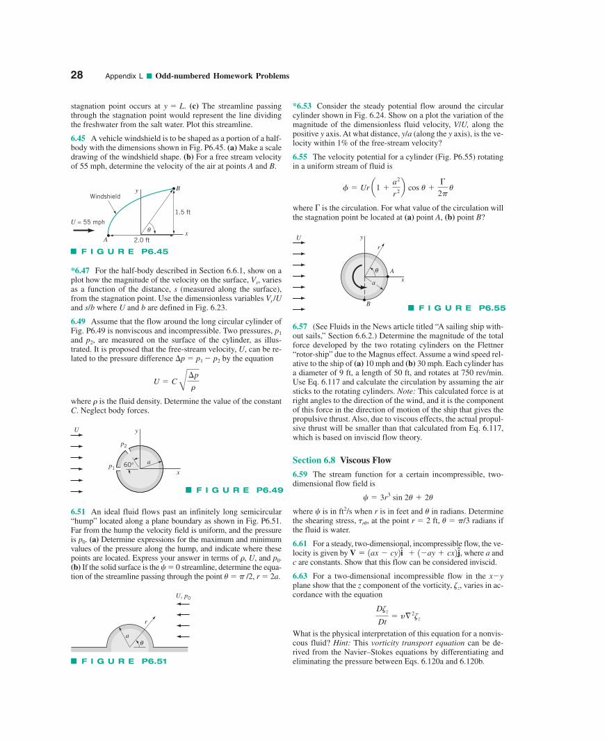
28 Appendix L ■ Odd-numbered Homework Problems
stagnation point occurs at (c) The streamline passingthrough the stagnation point would represent the line dividingthe freshwater from the salt water. Plot this streamline.
6.45 A vehicle windshield is to be shaped as a portion of a half-body with the dimensions shown in Fig. P6.45. (a) Make a scaledrawing of the windshield shape. (b) For a free stream velocityof 55 mph, determine the velocity of the air at points A and B.
y � L.
*6.47 For the half-body described in Section 6.6.1, show on aplot how the magnitude of the velocity on the surface, Vs, variesas a function of the distance, s (measured along the surface),from the stagnation point. Use the dimensionless variables Vs /Uand s/b where U and b are defined in Fig. 6.23.
6.49 Assume that the flow around the long circular cylinder ofFig. P6.49 is nonviscous and incompressible. Two pressures, p1
and p2, are measured on the surface of the cylinder, as illus-trated. It is proposed that the free-stream velocity, U, can be re-lated to the pressure difference �p � p1 � p2 by the equation
where � is the fluid density. Determine the value of the constantC. Neglect body forces.
U � C B¢p
�
*6.53 Consider the steady potential flow around the circularcylinder shown in Fig. 6.24. Show on a plot the variation of themagnitude of the dimensionless fluid velocity, V/U, along thepositive y axis. At what distance, y/a (along the y axis), is the ve-locity within 1% of the free-stream velocity?
6.55 The velocity potential for a cylinder (Fig. P6.55) rotatingin a uniform stream of fluid is
where is the circulation. For what value of the circulation willthe stagnation point be located at (a) point A, (b) point B?
�
� � Ur a1 �a2
r 2b cos � ��
2� �
6.57 (See Fluids in the News article titled “A sailing ship with-out sails,” Section 6.6.2.) Determine the magnitude of the totalforce developed by the two rotating cylinders on the Flettner“rotor-ship” due to the Magnus effect. Assume a wind speed rel-ative to the ship of (a) 10 mph and (b) 30 mph. Each cylinder hasa diameter of 9 ft, a length of 50 ft, and rotates at 750 rev/min.Use Eq. 6.117 and calculate the circulation by assuming the airsticks to the rotating cylinders. Note: This calculated force is atright angles to the direction of the wind, and it is the componentof this force in the direction of motion of the ship that gives thepropulsive thrust. Also, due to viscous effects, the actual propul-sive thrust will be smaller than that calculated from Eq. 6.117,which is based on inviscid flow theory.
Section 6.8 Viscous Flow
6.59 The stream function for a certain incompressible, two-dimensional flow field is
where � is in ft2/s when r is in feet and � in radians. Determinethe shearing stress, �r�, at the point r � 2 ft, � � �/3 radians ifthe fluid is water.
6.61 For a steady, two-dimensional, incompressible flow, the ve-locity is given by , where a andc are constants. Show that this flow can be considered inviscid.
6.63 For a two-dimensional incompressible flow in the x�yplane show that the z component of the vorticity, varies in ac-cordance with the equation
What is the physical interpretation of this equation for a nonvis-cous fluid? Hint: This vorticity transport equation can be de-rived from the Navier–Stokes equations by differentiating andeliminating the pressure between Eqs. 6.120a and 6.120b.
D z
Dt� y§ 2 z
z,
V � 1ax � cy2 i � 1�ay � cx2 j
� � 3r3 sin 2� � 2�
F I G U R E P6.45
2.0 ft
1.5 ft
y
xA
B
θU = 55 mph
Windshield
U
a60°
y
xp1
p2
F I G U R E P6.49
6.51 An ideal fluid flows past an infinitely long semicircular“hump” located along a plane boundary as shown in Fig. P6.51.Far from the hump the velocity field is uniform, and the pressureis p0. (a) Determine expressions for the maximum and minimumvalues of the pressure along the hump, and indicate where thesepoints are located. Express your answer in terms of �, U, and p0.(b) If the solid surface is the � � 0 streamline, determine the equa-tion of the streamline passing through the point � � � /2, r � 2a.
r
aθ
U, p0
F I G U R E P6.51
U
r
y
xA
B
θ
a
F I G U R E P6.55
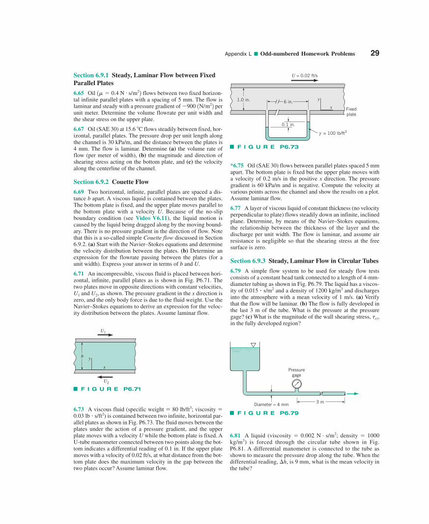
Appendix L ■ Odd-numbered Homework Problems 29
Section 6.9.1 Steady, Laminar Flow between FixedParallel Plates
6.65 Oil flows between two fixed horizon-tal infinite parallel plates with a spacing of 5 mm. The flow islaminar and steady with a pressure gradient of perunit meter. Determine the volume flowrate per unit width andthe shear stress on the upper plate.
6.67 Oil (SAE 30) at 15.6 C flows steadily between fixed, hor-izontal, parallel plates. The pressure drop per unit length alongthe channel is 30 kPa/m, and the distance between the plates is4 mm. The flow is laminar. Determine (a) the volume rate offlow (per meter of width), (b) the magnitude and direction ofshearing stress acting on the bottom plate, and (c) the velocityalong the centerline of the channel.
Section 6.9.2 Couette Flow
6.69 Two horizontal, infinite, parallel plates are spaced a dis-tance b apart. A viscous liquid is contained between the plates.The bottom plate is fixed, and the upper plate moves parallel tothe bottom plate with a velocity U. Because of the no-slipboundary condition (see Video V6.11), the liquid motion iscaused by the liquid being dragged along by the moving bound-ary. There is no pressure gradient in the direction of flow. Notethat this is a so-called simple Couette flow discussed in Section6.9.2. (a) Start with the Navier–Stokes equations and determinethe velocity distribution between the plates. (b) Determine anexpression for the flowrate passing between the plates (for aunit width). Express your answer in terms of b and U.
6.71 An incompressible, viscous fluid is placed between hori-zontal, infinite, parallel plates as is shown in Fig. P6.71. Thetwo plates move in opposite directions with constant velocities,U1 and U2, as shown. The pressure gradient in the x direction iszero, and the only body force is due to the fluid weight. Use theNavier–Stokes equations to derive an expression for the veloc-ity distribution between the plates. Assume laminar flow.
�900 1N/m22
1� � 0.4 N # s/m22
6.73 A viscous fluid (specific weight � 80 lb/ft3; viscosity �0.03 lb � s/ft2) is contained between two infinite, horizontal par-allel plates as shown in Fig. P6.73. The fluid moves between theplates under the action of a pressure gradient, and the upperplate moves with a velocity U while the bottom plate is fixed. AU-tube manometer connected between two points along the bot-tom indicates a differential reading of 0.1 in. If the upper platemoves with a velocity of 0.02 ft/s, at what distance from the bot-tom plate does the maximum velocity in the gap between thetwo plates occur? Assume laminar flow.
*6.75 Oil (SAE 30) flows between parallel plates spaced 5 mmapart. The bottom plate is fixed but the upper plate moves witha velocity of 0.2 m/s in the positive x direction. The pressuregradient is 60 kPa/m and is negative. Compute the velocity atvarious points across the channel and show the results on a plot.Assume laminar flow.
6.77 A layer of viscous liquid of constant thickness (no velocityperpendicular to plate) flows steadily down an infinite, inclinedplane. Determine, by means of the Navier–Stokes equations,the relationship between the thickness of the layer and thedischarge per unit width. The flow is laminar, and assume airresistance is negligible so that the shearing stress at the freesurface is zero.
Section 6.9.3 Steady, Laminar Flow in Circular Tubes
6.79 A simple flow system to be used for steady flow testsconsists of a constant head tank connected to a length of 4-mm-diameter tubing as shown in Fig. P6.79. The liquid has a viscos-ity of 0.015 � s/m2 and a density of 1200 kg/m3 and dischargesinto the atmosphere with a mean velocity of 1 m/s. (a) Verifythat the flow will be laminar. (b) The flow is fully developed inthe last 3 m of the tube. What is the pressure at the pressuregage? (c) What is the magnitude of the wall shearing stress, �rz,in the fully developed region?
b
x
y
U1
U2
F I G U R E P6.71
0.1 in.
6 in. y
x
1.0 in.
U = 0.02 ft/s
= 100 lb/ft3γ
Fixedplate
F I G U R E P6.73
Pressuregage
3 mDiameter = 4 mm
F I G U R E P6.79
6.81 A liquid (viscosity � 0.002 N . s/m2; density � 1000kg/m3) is forced through the circular tube shown in Fig.P6.81. A differential manometer is connected to the tube asshown to measure the pressure drop along the tube. When thedifferential reading, �h, is 9 mm, what is the mean velocity inthe tube?
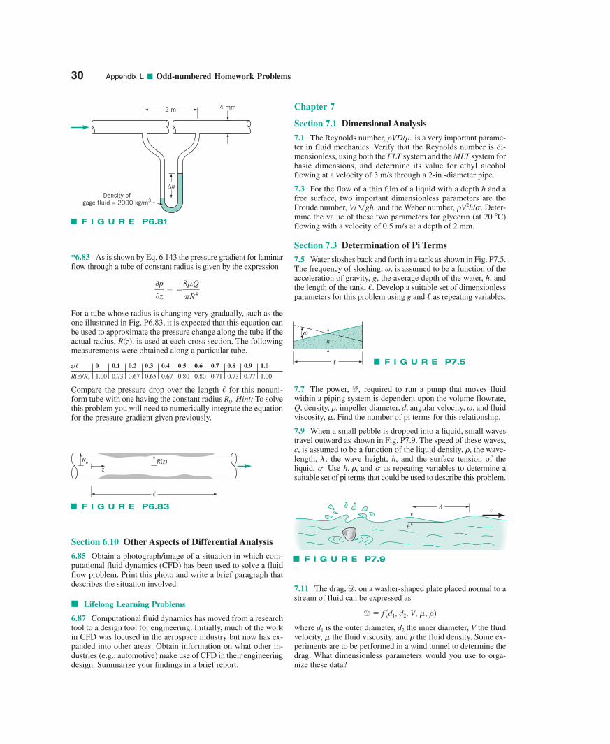
30 Appendix L ■ Odd-numbered Homework Problems
*6.83 As is shown by Eq. 6.143 the pressure gradient for laminarflow through a tube of constant radius is given by the expression
For a tube whose radius is changing very gradually, such as theone illustrated in Fig. P6.83, it is expected that this equation canbe used to approximate the pressure change along the tube if theactual radius, R(z), is used at each cross section. The followingmeasurements were obtained along a particular tube.
z/� 0 0.1 0.2 0.3 0.4 0.5 0.6 0.7 0.8 0.9 1.0
R(z)/Ro 1.00 0.73 0.67 0.65 0.67 0.80 0.80 0.71 0.73 0.77 1.00
Compare the pressure drop over the length � for this nonuni-form tube with one having the constant radius R0. Hint: To solvethis problem you will need to numerically integrate the equationfor the pressure gradient given previously.
0p
0z� �
8�Q
�R4
Section 6.10 Other Aspects of Differential Analysis
6.85 Obtain a photograph/image of a situation in which com-putational fluid dynamics (CFD) has been used to solve a fluidflow problem. Print this photo and write a brief paragraph thatdescribes the situation involved.
■ Lifelong Learning Problems
6.87 Computational fluid dynamics has moved from a researchtool to a design tool for engineering. Initially, much of the workin CFD was focused in the aerospace industry but now has ex-panded into other areas. Obtain information on what other in-dustries (e.g., automotive) make use of CFD in their engineeringdesign. Summarize your findings in a brief report.
Chapter 7
Section 7.1 Dimensional Analysis
7.1 The Reynolds number, �VD/�, is a very important parame-ter in fluid mechanics. Verify that the Reynolds number is di-mensionless, using both the FLT system and the MLT system forbasic dimensions, and determine its value for ethyl alcoholflowing at a velocity of 3 m/s through a 2-in.-diameter pipe.
7.3 For the flow of a thin film of a liquid with a depth h and afree surface, two important dimensionless parameters are theFroude number, and the Weber number, �V2h/�. Deter-mine the value of these two parameters for glycerin (at 20 C)flowing with a velocity of 0.5 m/s at a depth of 2 mm.
Section 7.3 Determination of Pi Terms
7.5 Water sloshes back and forth in a tank as shown in Fig. P7.5.The frequency of sloshing, �, is assumed to be a function of theacceleration of gravity, g, the average depth of the water, h, andthe length of the tank, �. Develop a suitable set of dimensionlessparameters for this problem using g and � as repeating variables.
V/1gh,
7.7 The power, , required to run a pump that moves fluidwithin a piping system is dependent upon the volume flowrate,Q, density, �, impeller diameter, d, angular velocity, , and fluidviscosity, �. Find the number of pi terms for this relationship.
7.9 When a small pebble is dropped into a liquid, small wavestravel outward as shown in Fig. P7.9. The speed of these waves,c, is assumed to be a function of the liquid density, , the wave-length, , the wave height, h, and the surface tension of the liquid, . Use , and as repeating variables to determine asuitable set of pi terms that could be used to describe this problem.
�h, ���
�
�
p
7.11 The drag, on a washer-shaped plate placed normal to astream of fluid can be expressed as
where is the outer diameter, the inner diameter, V the fluidvelocity, the fluid viscosity, and the fluid density. Some ex-periments are to be performed in a wind tunnel to determine thedrag. What dimensionless parameters would you use to orga-nize these data?
��d2d1
d � f 1d1, d2, V, �, �2
d,
2 m 4 mm
ΔhDensity of
gage fluid = 2000 kg/m3
F I G U R E P6.81
Ro
zR(z)
�
F I G U R E P6.83
h
�
ω
F I G U R E P7.5
λ
h
c
F I G U R E P7.9
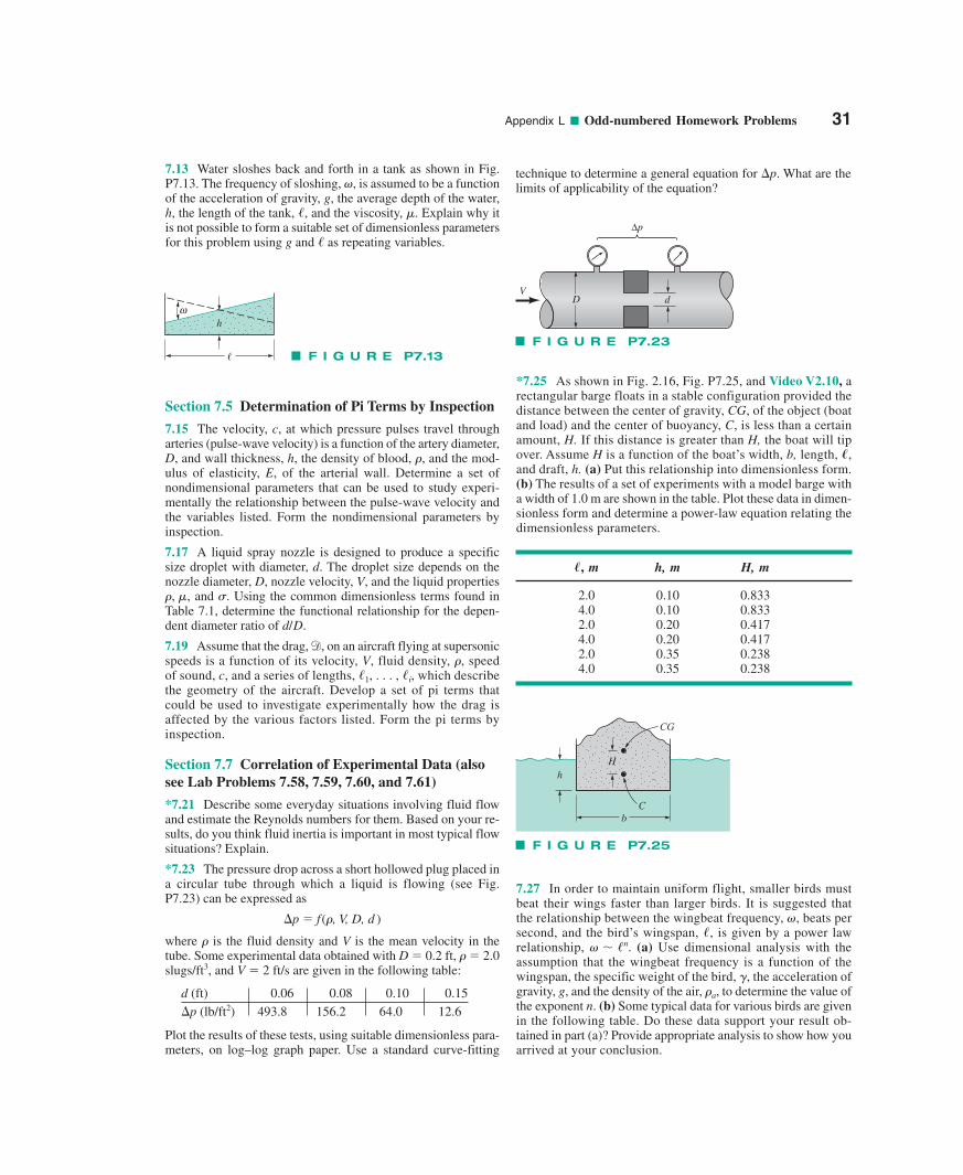
Appendix L ■ Odd-numbered Homework Problems 31
7.13 Water sloshes back and forth in a tank as shown in Fig.P7.13. The frequency of sloshing, is assumed to be a functionof the acceleration of gravity, g, the average depth of the water,h, the length of the tank, , and the viscosity, . Explain why itis not possible to form a suitable set of dimensionless parametersfor this problem using g and as repeating variables./
�/
�,technique to determine a general equation for �p. What are thelimits of applicability of the equation?
Section 7.5 Determination of Pi Terms by Inspection
7.15 The velocity, c, at which pressure pulses travel througharteries (pulse-wave velocity) is a function of the artery diameter,D, and wall thickness, h, the density of blood, �, and the mod-ulus of elasticity, E, of the arterial wall. Determine a set ofnondimensional parameters that can be used to study experi-mentally the relationship between the pulse-wave velocity andthe variables listed. Form the nondimensional parameters byinspection.
7.17 A liquid spray nozzle is designed to produce a specificsize droplet with diameter, d. The droplet size depends on thenozzle diameter, D, nozzle velocity, V, and the liquid properties
and . Using the common dimensionless terms found inTable 7.1, determine the functional relationship for the depen-dent diameter ratio of
7.19 Assume that the drag, on an aircraft flying at supersonicspeeds is a function of its velocity, V, fluid density, speedof sound, c, and a series of lengths, which describethe geometry of the aircraft. Develop a set of pi terms thatcould be used to investigate experimentally how the drag isaffected by the various factors listed. Form the pi terms byinspection.
Section 7.7 Correlation of Experimental Data (alsosee Lab Problems 7.58, 7.59, 7.60, and 7.61)
*7.21 Describe some everyday situations involving fluid flowand estimate the Reynolds numbers for them. Based on your re-sults, do you think fluid inertia is important in most typical flowsituations? Explain.
*7.23 The pressure drop across a short hollowed plug placed ina circular tube through which a liquid is flowing (see Fig.P7.23) can be expressed as
�p � f(�, V, D, d )
where � is the fluid density and V is the mean velocity in thetube. Some experimental data obtained with D � 0.2 ft, � � 2.0slugs/ft3, and V � 2 ft/s are given in the following table:
d (ft) 0.06 0.08 0.10 0.15�p (lb/ft2) 493.8 156.2 64.0 12.6
Plot the results of these tests, using suitable dimensionless para-meters, on log–log graph paper. Use a standard curve-fitting
/1, . . . , /i,�,
d,
d/D.
��, �,
*7.25 As shown in Fig. 2.16, Fig. P7.25, and Video V2.10, arectangular barge floats in a stable configuration provided thedistance between the center of gravity, CG, of the object (boatand load) and the center of buoyancy, C, is less than a certainamount, H. If this distance is greater than H, the boat will tipover. Assume H is a function of the boat’s width, b, length, �,and draft, h. (a) Put this relationship into dimensionless form.(b) The results of a set of experiments with a model barge witha width of 1.0 m are shown in the table. Plot these data in dimen-sionless form and determine a power-law equation relating thedimensionless parameters.
, m h, m H, m
2.0 0.10 0.8334.0 0.10 0.8332.0 0.20 0.4174.0 0.20 0.4172.0 0.35 0.2384.0 0.35 0.238
�
7.27 In order to maintain uniform flight, smaller birds mustbeat their wings faster than larger birds. It is suggested thatthe relationship between the wingbeat frequency, , beats persecond, and the bird’s wingspan, , is given by a power lawrelationship, (a) Use dimensional analysis with theassumption that the wingbeat frequency is a function of thewingspan, the specific weight of the bird, , the acceleration ofgravity, g, and the density of the air, , to determine the value ofthe exponent n. (b) Some typical data for various birds are givenin the following table. Do these data support your result ob-tained in part (a)? Provide appropriate analysis to show how youarrived at your conclusion.
�a
�
� � /n./
�
h
�
ω
F I G U R E P7.13
CG
Cb
Hh
F I G U R E P7.25
DV
d
Δp
F I G U R E P7.23
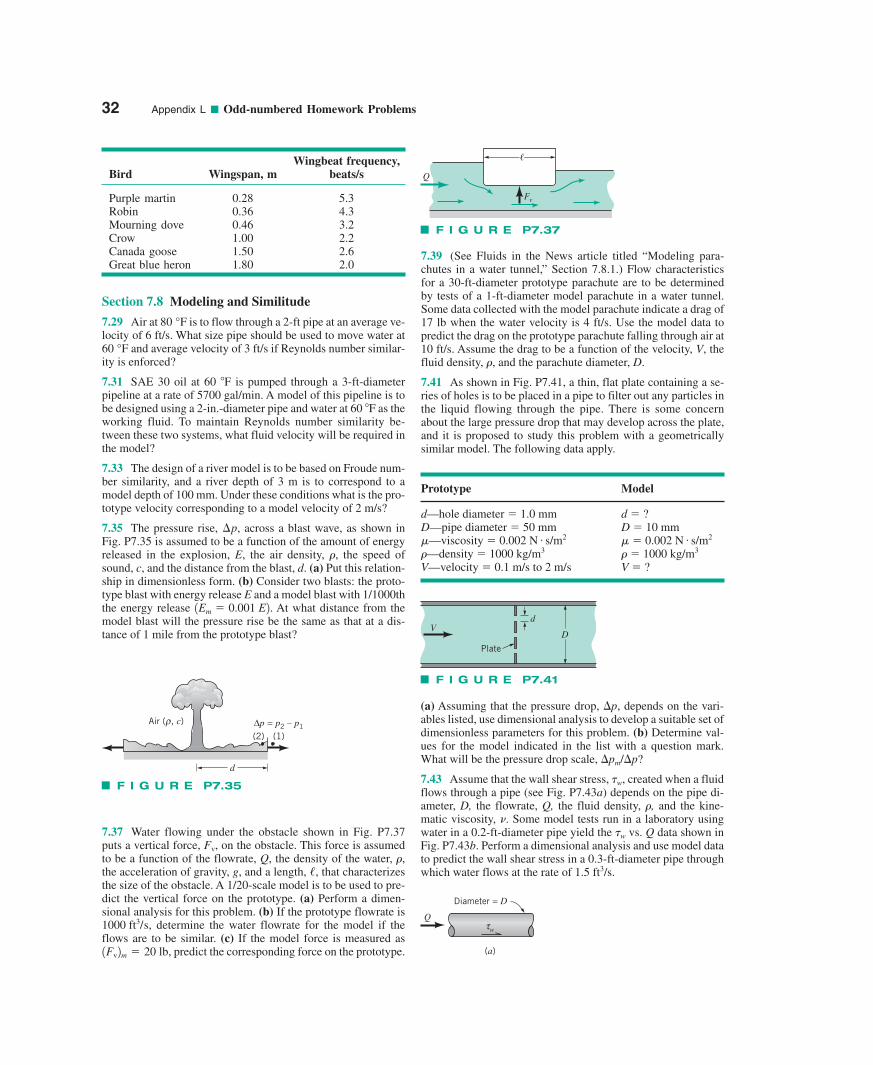
32 Appendix L ■ Odd-numbered Homework Problems
Wingbeat frequency,Bird Wingspan, m beats/s
Purple martin 0.28 5.3Robin 0.36 4.3Mourning dove 0.46 3.2Crow 1.00 2.2Canada goose 1.50 2.6Great blue heron 1.80 2.0
Section 7.8 Modeling and Similitude
7.29 Air at is to flow through a 2-ft pipe at an average ve-locity of 6 ft/s. What size pipe should be used to move water at
and average velocity of 3 ft/s if Reynolds number similar-ity is enforced?
7.31 SAE 30 oil at 60 F is pumped through a 3-ft-diameterpipeline at a rate of 5700 gal/min. A model of this pipeline is tobe designed using a 2-in.-diameter pipe and water at 60 F as theworking fluid. To maintain Reynolds number similarity be-tween these two systems, what fluid velocity will be required inthe model?
7.33 The design of a river model is to be based on Froude num-ber similarity, and a river depth of 3 m is to correspond to amodel depth of 100 mm. Under these conditions what is the pro-totype velocity corresponding to a model velocity of 2 m/s?
7.35 The pressure rise, across a blast wave, as shown inFig. P7.35 is assumed to be a function of the amount of energyreleased in the explosion, E, the air density, the speed ofsound, c, and the distance from the blast, d. (a) Put this relation-ship in dimensionless form. (b) Consider two blasts: the proto-type blast with energy release E and a model blast with 1/1000ththe energy release At what distance from themodel blast will the pressure rise be the same as that at a dis-tance of 1 mile from the prototype blast?
1Em � 0.001 E2.
�,
¢p,
60 °F
80 °F
7.37 Water flowing under the obstacle shown in Fig. P7.37puts a vertical force, , on the obstacle. This force is assumedto be a function of the flowrate, Q, the density of the water, ,the acceleration of gravity, g, and a length, , that characterizesthe size of the obstacle. A 1/20-scale model is to be used to pre-dict the vertical force on the prototype. (a) Perform a dimen-sional analysis for this problem. (b) If the prototype flowrate is
, determine the water flowrate for the model if theflows are to be similar. (c) If the model force is measured as
, predict the corresponding force on the prototype.1Fv2m � 20 lb
1000 ft3/s
/�
Fv
7.39 (See Fluids in the News article titled “Modeling para-chutes in a water tunnel,” Section 7.8.1.) Flow characteristicsfor a 30-ft-diameter prototype parachute are to be determinedby tests of a 1-ft-diameter model parachute in a water tunnel.Some data collected with the model parachute indicate a drag of17 lb when the water velocity is 4 ft/s. Use the model data topredict the drag on the prototype parachute falling through air at10 ft/s. Assume the drag to be a function of the velocity, V, thefluid density, , and the parachute diameter, D.
7.41 As shown in Fig. P7.41, a thin, flat plate containing a se-ries of holes is to be placed in a pipe to filter out any particles inthe liquid flowing through the pipe. There is some concernabout the large pressure drop that may develop across the plate,and it is proposed to study this problem with a geometricallysimilar model. The following data apply.
Prototype Model
d—hole diameter � 1.0 mm d � ?D—pipe diameter � 50 mm D � 10 mm�—viscosity � 0.002 N s/m2 � � 0.002 N s/m2
�—density � 1000 kg/m3 � � 1000 kg/m3
V—velocity � 0.1 m/s to 2 m/s V � ?
##
�
(a) Assuming that the pressure drop, �p, depends on the vari-ables listed, use dimensional analysis to develop a suitable set ofdimensionless parameters for this problem. (b) Determine val-ues for the model indicated in the list with a question mark.What will be the pressure drop scale, �pm/�p?
7.43 Assume that the wall shear stress, �w, created when a fluidflows through a pipe (see Fig. P7.43a) depends on the pipe di-ameter, D, the flowrate, Q, the fluid density, �, and the kine-matic viscosity, �. Some model tests run in a laboratory usingwater in a 0.2-ft-diameter pipe yield the �w vs. Q data shown inFig. P7.43b. Perform a dimensional analysis and use model datato predict the wall shear stress in a 0.3-ft-diameter pipe throughwhich water flows at the rate of 1.5 ft3/s.
Air ( , c)ρ(2)Δp = p2 – p1
(1)
d
F I G U R E P7.35
Plate
VD
d
F I G U R E P7.41
Diameter = D
(a)
τw
Q
Q
Fv
�
F I G U R E P7.37
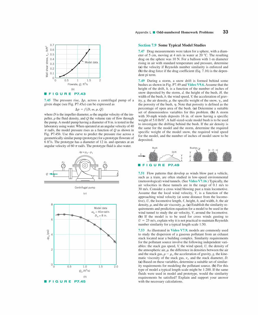
Appendix L ■ Odd-numbered Homework Problems 33
7.45 The pressure rise, �p, across a centrifugal pump of agiven shape (see Fig. P7.45a) can be expressed as
where D is the impeller diameter, � the angular velocity of the im-peller, � the fluid density, and Q the volume rate of flow throughthe pump. A model pump having a diameter of 8 in. is tested in thelaboratory using water. When operated at an angular velocity of 40
rad/s, the model pressure rises as a function of Q as shown inFig. P7.45b. Use this curve to predict the pressure rise across ageometrically similar pump (prototype) for a prototype flowrate of6 ft3/s. The prototype has a diameter of 12 in. and operates at anangular velocity of 60 rad/s. The prototype fluid is also water.�
�
¢p � f 1D, �, �, Q2
Section 7.9 Some Typical Model Studies
7.47 Drag measurements were taken for a sphere, with a diam-eter of 5 cm, moving at 4 m/s in water at 20 C. The resultingdrag on the sphere was 10 N. For a balloon with 1-m diameterrising in air with standard temperature and pressure, determine(a) the velocity if Reynolds number similarity is enforced and(b) the drag force if the drag coefficient (Eq. 7.16) is the depen-dent pi term.
7.49 During a storm, a snow drift is formed behind somebushes as shown in Fig. P7.49 and Video V9.6. Assume that theheight of the drift, h, is a function of the number of inches ofsnow deposited by the storm, d, the height of the bush, H, thewidth of the bush, b, the wind speed, V, the acceleration of grav-ity, g, the air density, �, the specific weight of the snow, �s, andthe porosity of the bush, �. Note that porosity is defined as thepercentage of open area of the bush. (a) Determine a suitableset of dimensionless variables for this problem. (b) A stormwith 30-mph winds deposits 16 in. of snow having a specificweight of 5.0 lb/ft3. A half-sized-scale model bush is to be usedto investigate the drifting behind the bush. If the air density isthe same for the model and the storm, determine the requiredspecific weight of the model snow, the required wind speedfor the model, and the number of inches of model snow to bedeposited.
7.51 Flow patterns that develop as winds blow past a vehicle,such as a train, are often studied in low-speed environmental(meteorological) wind tunnels. (See Video V7.16.) Typically, theair velocities in these tunnels are in the range of 0.1 m/s to 30 m/s. Consider a cross wind blowing past a train locomotive.Assume that the local wind velocity, V, is a function of the approaching wind velocity (at some distance from the locomo-tive), U, the locomotive length, height, h, and width, b, the airdensity, and the air viscosity, (a) Establish the similarity re-quirements and prediction equation for a model to be used in thewind tunnel to study the air velocity, V, around the locomotive.(b) If the model is to be used for cross winds gusting to
explain why it is not practical to maintain Reynoldsnumber similarity for a typical length scale 1:50.
7.53 As illustrated in Video V7.9, models are commonly usedto study the dispersion of a gaseous pollutant from an exhauststack located near a building complex. Similarity requirementsfor the pollutant source involve the following independent vari-ables: the stack gas speed, V, the wind speed, U, the density ofthe atmospheric air, �, the difference in densities between the airand the stack gas, � � �s, the acceleration of gravity, g, the kine-matic viscosity of the stack gas, �s, and the stack diameter, D.(a) Based on these variables, determine a suitable set of similar-ity requirements for modeling the pollutant source. (b) For thistype of model a typical length scale might be 1:200. If the samefluids were used in model and prototype, would the similarityrequirements be satisfied? Explain and support your answerwith the necessary calculations.
U � 25 m/s,
�.�,/,
Q
Centrifugal pump
p2 p1
p = p2 – p1Δ
(a)
0
2
4
6
8
p m (p
si)
Δ
Qm (ft3/s)
(b)
0 0.5 1.0 1.5 2.0
Model data m = 40 rad/s ω π
Dm = 8 in.
F I G U R E P7.45
F I G U R E P7.49
Bush Bushes
V
b
Hh
Drift
0.7
0.6
0.5
0.4
0.3
0.2
0.1
00 0.5 1
Flowrate, Q, ft3/s1.5 2
Model data
(b)
Wal
l she
ar s
tres
s,
w, lb
/ft2
τ
F I G U R E P7.43
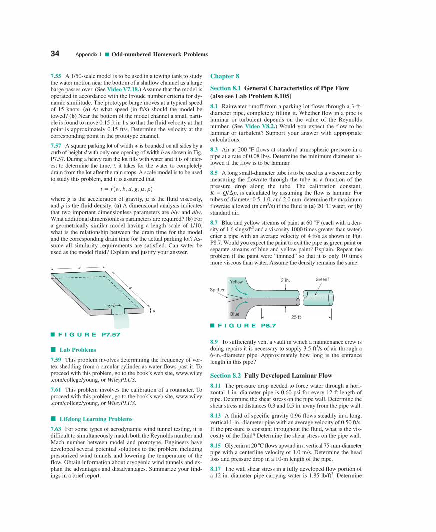
34 Appendix L ■ Odd-numbered Homework Problems
7.55 A 1/50-scale model is to be used in a towing tank to studythe water motion near the bottom of a shallow channel as a largebarge passes over. (See Video V7.18.) Assume that the model isoperated in accordance with the Froude number criteria for dy-namic similitude. The prototype barge moves at a typical speedof 15 knots. (a) At what speed (in ft/s) should the model betowed? (b) Near the bottom of the model channel a small parti-cle is found to move 0.15 ft in 1 s so that the fluid velocity at thatpoint is approximately 0.15 ft/s. Determine the velocity at thecorresponding point in the prototype channel.
7.57 A square parking lot of width w is bounded on all sides by acurb of height d with only one opening of width b as shown in Fig.P7.57. During a heavy rain the lot fills with water and it is of inter-est to determine the time, t, it takes for the water to completelydrain from the lot after the rain stops. A scale model is to be usedto study this problem, and it is assumed that
where g is the acceleration of gravity, � is the fluid viscosity,and � is the fluid density. (a) A dimensional analysis indicatesthat two important dimensionless parameters are b/w and d/w.What additional dimensionless parameters are required? (b) Fora geometrically similar model having a length scale of 1/10,what is the relationship between the drain time for the modeland the corresponding drain time for the actual parking lot? As-sume all similarity requirements are satisfied. Can water beused as the model fluid? Explain and justify your answer.
t � f 1w, b, d, g, �, �2
■ Lab Problems
7.59 This problem involves determining the frequency of vor-tex shedding from a circular cylinder as water flows past it. Toproceed with this problem, go to the book’s web site, www.wiley.com/college/young, or WileyPLUS.
7.61 This problem involves the calibration of a rotameter. Toproceed with this problem, go to the book’s web site, www.wiley.com/college/young, or WileyPLUS.
■ Lifelong Learning Problems
7.63 For some types of aerodynamic wind tunnel testing, it isdifficult to simultaneously match both the Reynolds number andMach number between model and prototype. Engineers havedeveloped several potential solutions to the problem includingpressurized wind tunnels and lowering the temperature of theflow. Obtain information about cryogenic wind tunnels and ex-plain the advantages and disadvantages. Summarize your find-ings in a brief report.
Chapter 8
Section 8.1 General Characteristics of Pipe Flow(also see Lab Problem 8.105)
8.1 Rainwater runoff from a parking lot flows through a 3-ft-diameter pipe, completely filling it. Whether flow in a pipe islaminar or turbulent depends on the value of the Reynoldsnumber. (See Video V8.2.) Would you expect the flow to belaminar or turbulent? Support your answer with appropriatecalculations.
8.3 Air at 200 F flows at standard atmospheric pressure in apipe at a rate of 0.08 lb/s. Determine the minimum diameter al-lowed if the flow is to be laminar.
8.5 A long small-diameter tube is to be used as a viscometer bymeasuring the flowrate through the tube as a function of thepressure drop along the tube. The calibration constant,
is calculated by assuming the flow is laminar. Fortubes of diameter 0.5, 1.0, and 2.0 mm, determine the maximumflowrate allowed (in cm3/s) if the fluid is (a) 20 C water, or (b)standard air.
8.7 Blue and yellow streams of paint at (each with a den-sity of 1.6 slugs/ft3 and a viscosity 1000 times greater than water)enter a pipe with an average velocity of as shown in Fig.P8.7. Would you expect the paint to exit the pipe as green paint orseparate streams of blue and yellow paint? Explain. Repeat theproblem if the paint were “thinned” so that it is only 10 timesmore viscous than water. Assume the density remains the same.
4 ft/s
60 °F
K � Q/¢p,
8.9 To sufficiently vent a vault in which a maintenance crew isdoing repairs it is necessary to supply 3.5 ft3/s of air through a6-in.-diameter pipe. Approximately how long is the entrancelength in this pipe?
Section 8.2 Fully Developed Laminar Flow
8.11 The pressure drop needed to force water through a hori-zontal 1-in.-diameter pipe is 0.60 psi for every 12-ft length ofpipe. Determine the shear stress on the pipe wall. Determine theshear stress at distances 0.3 and 0.5 in. away from the pipe wall.
8.13 A fluid of specific gravity 0.96 flows steadily in a long,vertical 1-in.-diameter pipe with an average velocity of 0.50 ft/s.If the pressure is constant throughout the fluid, what is the vis-cosity of the fluid? Determine the shear stress on the pipe wall.
8.15 Glycerin at 20 C flows upward in a vertical 75-mm-diameterpipe with a centerline velocity of 1.0 m/s. Determine the headloss and pressure drop in a 10-m length of the pipe.
8.17 The wall shear stress in a fully developed flow portion ofa 12-in.-diameter pipe carrying water is 1.85 lb/ft2. Determine
d
w
w
b
F I G U R E P7.57
F I G U R E P8.7
25 ft
2 in.
Blue
Green?Yellow
Splitter
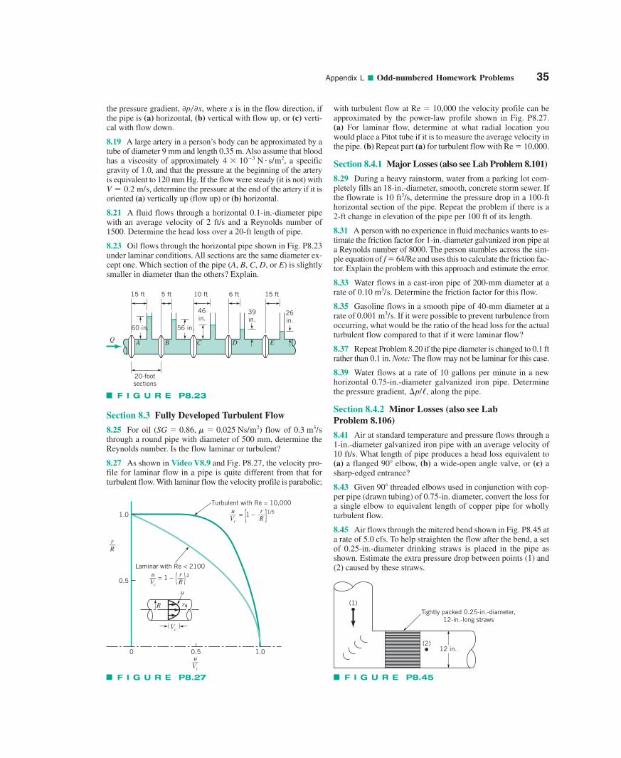
Appendix L ■ Odd-numbered Homework Problems 35
the pressure gradient, where x is in the flow direction, ifthe pipe is (a) horizontal, (b) vertical with flow up, or (c) verti-cal with flow down.
8.19 A large artery in a person’s body can be approximated by atube of diameter 9 mm and length 0.35 m. Also assume that bloodhas a viscosity of approximately a specificgravity of 1.0, and that the pressure at the beginning of the arteryis equivalent to 120 mm Hg. If the flow were steady (it is not) with
determine the pressure at the end of the artery if it isoriented (a) vertically up (flow up) or (b) horizontal.
8.21 A fluid flows through a horizontal 0.1-in.-diameter pipewith an average velocity of 2 ft/s and a Reynolds number of1500. Determine the head loss over a 20-ft length of pipe.
8.23 Oil flows through the horizontal pipe shown in Fig. P8.23under laminar conditions. All sections are the same diameter ex-cept one. Which section of the pipe (A, B, C, D, or E) is slightlysmaller in diameter than the others? Explain.
V � 0.2 m/s,
4 10�3 N # s/m2,
0p�0x,
Section 8.3 Fully Developed Turbulent Flow
8.25 For oil ( ) flow of through a round pipe with diameter of 500 mm, determine theReynolds number. Is the flow laminar or turbulent?
8.27 As shown in Video V8.9 and Fig. P8.27, the velocity pro-file for laminar flow in a pipe is quite different from that forturbulent flow. With laminar flow the velocity profile is parabolic;
0.3 m3/sSG � 0.86, � � 0.025 Ns/m2
with turbulent flow at Re � 10,000 the velocity profile can beapproximated by the power-law profile shown in Fig. P8.27. (a) For laminar flow, determine at what radial location youwould place a Pitot tube if it is to measure the average velocity inthe pipe. (b) Repeat part (a) for turbulent flow with Re � 10,000.
Section 8.4.1 Major Losses (also see Lab Problem 8.101)
8.29 During a heavy rainstorm, water from a parking lot com-pletely fills an 18-in.-diameter, smooth, concrete storm sewer. Ifthe flowrate is 10 ft3/s, determine the pressure drop in a 100-fthorizontal section of the pipe. Repeat the problem if there is a 2-ft change in elevation of the pipe per 100 ft of its length.
8.31 A person with no experience in fluid mechanics wants to es-timate the friction factor for 1-in.-diameter galvanized iron pipe ata Reynolds number of 8000. The person stumbles across the sim-ple equation of f � 64/Re and uses this to calculate the friction fac-tor. Explain the problem with this approach and estimate the error.
8.33 Water flows in a cast-iron pipe of 200-mm diameter at arate of . Determine the friction factor for this flow.
8.35 Gasoline flows in a smooth pipe of 40-mm diameter at arate of If it were possible to prevent turbulence fromoccurring, what would be the ratio of the head loss for the actualturbulent flow compared to that if it were laminar flow?
8.37 Repeat Problem 8.20 if the pipe diameter is changed to 0.1 ftrather than 0.1 in. Note: The flow may not be laminar for this case.
8.39 Water flows at a rate of 10 gallons per minute in a newhorizontal 0.75-in.-diameter galvanized iron pipe. Determinethe pressure gradient, along the pipe.
Section 8.4.2 Minor Losses (also see Lab Problem 8.106)
8.41 Air at standard temperature and pressure flows through a1-in.-diameter galvanized iron pipe with an average velocity of10 ft/s. What length of pipe produces a head loss equivalent to(a) a flanged 90 elbow, (b) a wide-open angle valve, or (c) asharp-edged entrance?
8.43 Given 90 threaded elbows used in conjunction with cop-per pipe (drawn tubing) of 0.75-in. diameter, convert the loss fora single elbow to equivalent length of copper pipe for whollyturbulent flow.
8.45 Air flows through the mitered bend shown in Fig. P8.45 ata rate of 5.0 cfs. To help straighten the flow after the bend, a setof 0.25-in.-diameter drinking straws is placed in the pipe asshown. Estimate the extra pressure drop between points (1) and(2) caused by these straws.
¢p//,
0.001 m3/s.
0.10 m3/s
F I G U R E P8.23
Q
15 ft
60 in. 56 in.
5 ft 10 ft 6 ft 15 ft
46in.
39in.
26in.
EDCBA
20-footsections
F I G U R E P8.27
1.0
0.5
0 0.5 1.0
r__R
r__R
u__Vc
u__Vc
Laminar with Re < 2100
= 1 – 2( )
r__R
u__Vc
Turbulent with Re = 10,000
= 1 – 1/5[ ]
R r
u
Vc
F I G U R E P8.45
(1)
(2)12 in.
Tightly packed 0.25-in.-diameter,12-in.-long straws
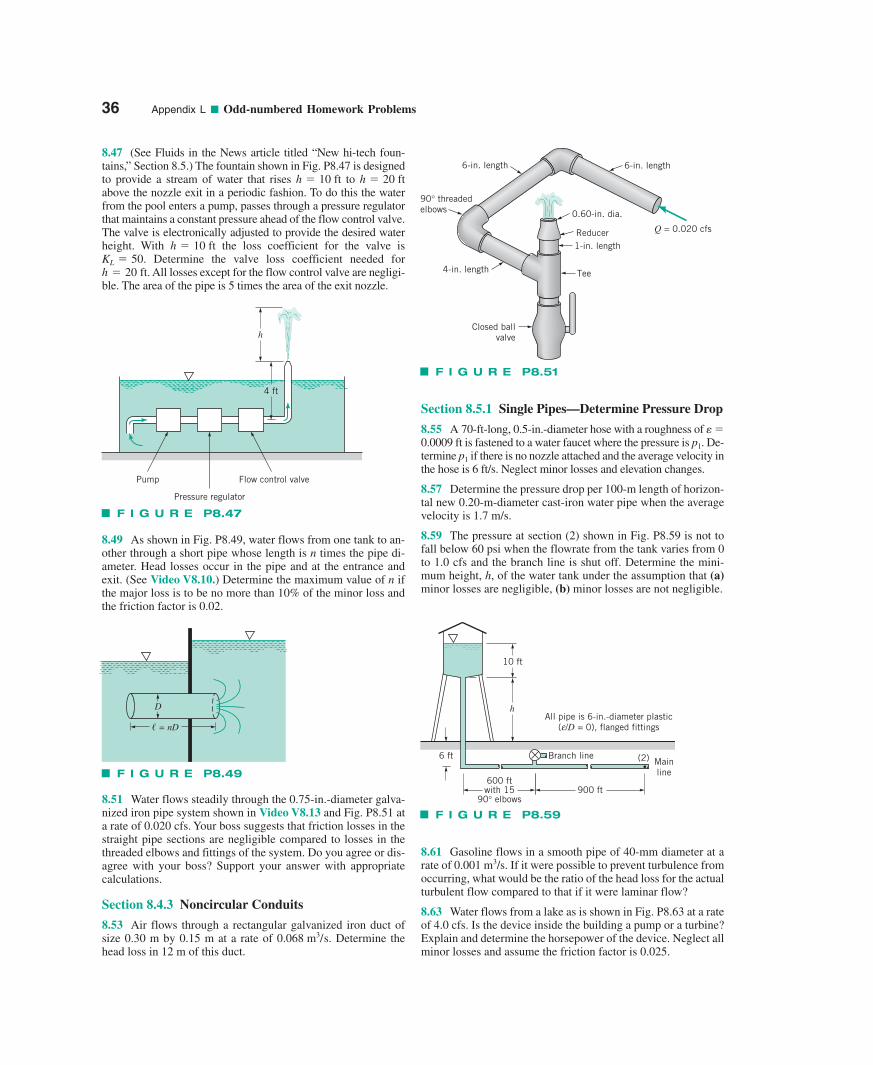
36 Appendix L ■ Odd-numbered Homework Problems
8.47 (See Fluids in the News article titled “New hi-tech foun-tains,” Section 8.5.) The fountain shown in Fig. P8.47 is designedto provide a stream of water that rises to above the nozzle exit in a periodic fashion. To do this the waterfrom the pool enters a pump, passes through a pressure regulatorthat maintains a constant pressure ahead of the flow control valve.The valve is electronically adjusted to provide the desired waterheight. With the loss coefficient for the valve is
Determine the valve loss coefficient needed forAll losses except for the flow control valve are negligi-
ble. The area of the pipe is 5 times the area of the exit nozzle.h � 20 ft.KL � 50.
h � 10 ft
h � 20 fth � 10 ft
8.49 As shown in Fig. P8.49, water flows from one tank to an-other through a short pipe whose length is n times the pipe di-ameter. Head losses occur in the pipe and at the entrance andexit. (See Video V8.10.) Determine the maximum value of n ifthe major loss is to be no more than 10% of the minor loss andthe friction factor is 0.02.
8.51 Water flows steadily through the 0.75-in.-diameter galva-nized iron pipe system shown in Video V8.13 and Fig. P8.51 ata rate of 0.020 cfs. Your boss suggests that friction losses in thestraight pipe sections are negligible compared to losses in thethreaded elbows and fittings of the system. Do you agree or dis-agree with your boss? Support your answer with appropriatecalculations.
Section 8.4.3 Noncircular Conduits
8.53 Air flows through a rectangular galvanized iron duct ofsize 0.30 m by 0.15 m at a rate of Determine thehead loss in 12 m of this duct.
0.068 m3/s.
Section 8.5.1 Single Pipes—Determine Pressure Drop
8.55 A 70-ft-long, 0.5-in.-diameter hose with a roughness of e�0.0009 ft is fastened to a water faucet where the pressure is p1. De-termine p1 if there is no nozzle attached and the average velocity inthe hose is 6 ft/s. Neglect minor losses and elevation changes.
8.57 Determine the pressure drop per 100-m length of horizon-tal new 0.20-m-diameter cast-iron water pipe when the averagevelocity is 1.7 m/s.
8.59 The pressure at section (2) shown in Fig. P8.59 is not tofall below 60 psi when the flowrate from the tank varies from 0to 1.0 cfs and the branch line is shut off. Determine the mini-mum height, h, of the water tank under the assumption that (a)minor losses are negligible, (b) minor losses are not negligible.
8.61 Gasoline flows in a smooth pipe of 40-mm diameter at arate of 0.001 m3/s. If it were possible to prevent turbulence fromoccurring, what would be the ratio of the head loss for the actualturbulent flow compared to that if it were laminar flow?
8.63 Water flows from a lake as is shown in Fig. P8.63 at a rateof 4.0 cfs. Is the device inside the building a pump or a turbine?Explain and determine the horsepower of the device. Neglect allminor losses and assume the friction factor is 0.025.
F I G U R E P8.47
4 ft
Pump Flow control valve
Pressure regulator
h
F I G U R E P8.49
D
� = nD
F I G U R E P8.51
6-in. length 6-in. length
4-in. length
Closed ballvalve
90° threadedelbows 0.60-in. dia.
Reducer Q = 0.020 cfs
1-in. length
Tee
F I G U R E P8.59
Branch line (2) Mainline
6 ft
10 ft
All pipe is 6-in.-diameter plastic( /D = 0), flanged fittings
h
600 ftwith 15
90° elbows900 ft
e
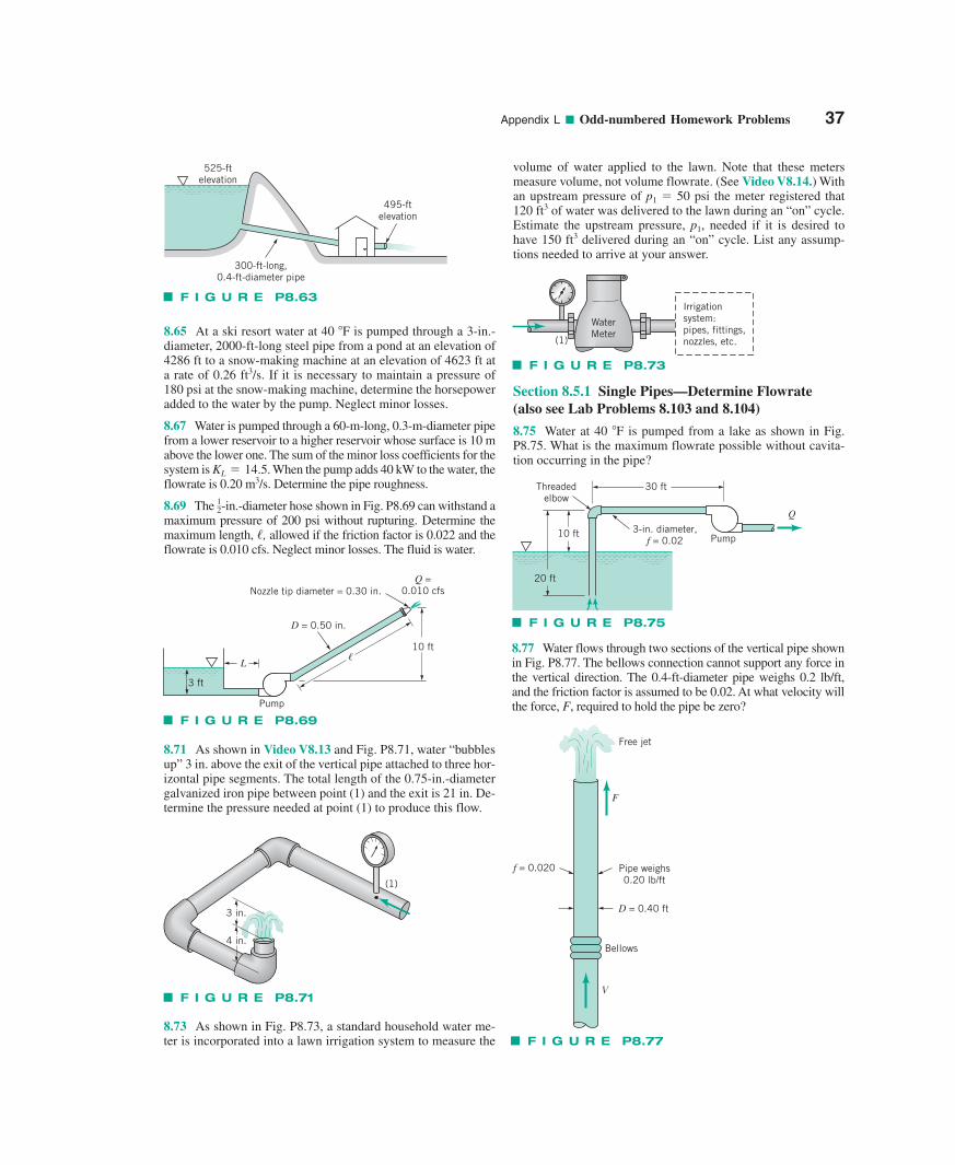
Appendix L ■ Odd-numbered Homework Problems 37
8.65 At a ski resort water at 40 F is pumped through a 3-in.-diameter, 2000-ft-long steel pipe from a pond at an elevation of4286 ft to a snow-making machine at an elevation of 4623 ft ata rate of 0.26 ft3/s. If it is necessary to maintain a pressure of180 psi at the snow-making machine, determine the horsepoweradded to the water by the pump. Neglect minor losses.
8.67 Water is pumped through a 60-m-long, 0.3-m-diameter pipefrom a lower reservoir to a higher reservoir whose surface is 10 mabove the lower one. The sum of the minor loss coefficients for thesystem is . When the pump adds 40 kW to the water, theflowrate is 0.20 m3/s. Determine the pipe roughness.
8.69 The -in.-diameter hose shown in Fig. P8.69 can withstand amaximum pressure of 200 psi without rupturing. Determine themaximum length, �, allowed if the friction factor is 0.022 and theflowrate is 0.010 cfs. Neglect minor losses. The fluid is water.
12
KL � 14.5
8.71 As shown in Video V8.13 and Fig. P8.71, water “bubblesup” 3 in. above the exit of the vertical pipe attached to three hor-izontal pipe segments. The total length of the 0.75-in.-diametergalvanized iron pipe between point (1) and the exit is 21 in. De-termine the pressure needed at point (1) to produce this flow.
volume of water applied to the lawn. Note that these metersmeasure volume, not volume flowrate. (See Video V8.14.) Withan upstream pressure of p1 � 50 psi the meter registered that120 ft3 of water was delivered to the lawn during an “on” cycle.Estimate the upstream pressure, p1, needed if it is desired tohave 150 ft3 delivered during an “on” cycle. List any assump-tions needed to arrive at your answer.
Section 8.5.1 Single Pipes—Determine Flowrate(also see Lab Problems 8.103 and 8.104)
8.75 Water at 40 F is pumped from a lake as shown in Fig.P8.75. What is the maximum flowrate possible without cavita-tion occurring in the pipe?
8.77 Water flows through two sections of the vertical pipe shownin Fig. P8.77. The bellows connection cannot support any force inthe vertical direction. The 0.4-ft-diameter pipe weighs 0.2 lb/ft,and the friction factor is assumed to be 0.02. At what velocity willthe force, F, required to hold the pipe be zero?
525-ftelevation
300-ft-long,0.4-ft-diameter pipe
495-ftelevation
F I G U R E P8.63
3 ft
L
D = 0.50 in.
Nozzle tip diameter = 0.30 in.Q =
0.010 cfs
10 ft�
Pump
F I G U R E P8.69
F I G U R E P8.71
4 in.
3 in.
(1)
F I G U R E P8.73
(1)
Irrigationsystem:pipes, fittings,nozzles, etc.
WaterMeter
F I G U R E P8.75
Q
Pump3-in. diameter,
f = 0.02
30 ft
10 ft
20 ft
Threadedelbow
F I G U R E P8.77
Pipe weighs0.20 lb/ft
Bellows
Free jet
D = 0.40 ft
f = 0.020
F
V
8.73 As shown in Fig. P8.73, a standard household water me-ter is incorporated into a lawn irrigation system to measure the
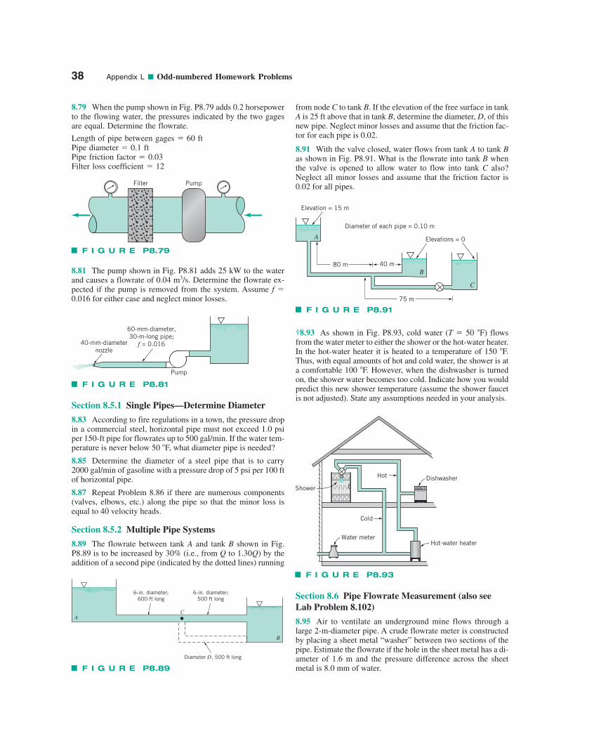
38 Appendix L ■ Odd-numbered Homework Problems
8.79 When the pump shown in Fig. P8.79 adds 0.2 horsepowerto the flowing water, the pressures indicated by the two gagesare equal. Determine the flowrate.
Length of pipe between gages � 60 ftPipe diameter � 0.1 ftPipe friction factor � 0.03Filter loss coefficient � 12
8.81 The pump shown in Fig. P8.81 adds 25 kW to the waterand causes a flowrate of 0.04 m3/s. Determine the flowrate ex-pected if the pump is removed from the system. Assume f �0.016 for either case and neglect minor losses.
Section 8.5.1 Single Pipes—Determine Diameter
8.83 According to fire regulations in a town, the pressure dropin a commercial steel, horizontal pipe must not exceed 1.0 psiper 150-ft pipe for flowrates up to 500 gal/min. If the water tem-perature is never below 50 F, what diameter pipe is needed?
8.85 Determine the diameter of a steel pipe that is to carry2000 gal/min of gasoline with a pressure drop of 5 psi per 100 ftof horizontal pipe.
8.87 Repeat Problem 8.86 if there are numerous components(valves, elbows, etc.) along the pipe so that the minor loss isequal to 40 velocity heads.
Section 8.5.2 Multiple Pipe Systems
8.89 The flowrate between tank A and tank B shown in Fig.P8.89 is to be increased by 30% (i.e., from Q to 1.30Q) by theaddition of a second pipe (indicated by the dotted lines) running
from node C to tank B. If the elevation of the free surface in tankA is 25 ft above that in tank B, determine the diameter, D, of thisnew pipe. Neglect minor losses and assume that the friction fac-tor for each pipe is 0.02.
8.91 With the valve closed, water flows from tank A to tank Bas shown in Fig. P8.91. What is the flowrate into tank B whenthe valve is opened to allow water to flow into tank C also? Neglect all minor losses and assume that the friction factor is0.02 for all pipes.
†8.93 As shown in Fig. P8.93, cold water (T � 50 F) flowsfrom the water meter to either the shower or the hot-water heater.In the hot-water heater it is heated to a temperature of 150 F.Thus, with equal amounts of hot and cold water, the shower is ata comfortable 100 F. However, when the dishwasher is turnedon, the shower water becomes too cold. Indicate how you wouldpredict this new shower temperature (assume the shower faucetis not adjusted). State any assumptions needed in your analysis.
Section 8.6 Pipe Flowrate Measurement (also seeLab Problem 8.102)
8.95 Air to ventilate an underground mine flows through alarge 2-m-diameter pipe. A crude flowrate meter is constructedby placing a sheet metal “washer” between two sections of thepipe. Estimate the flowrate if the hole in the sheet metal has a di-ameter of 1.6 m and the pressure difference across the sheetmetal is 8.0 mm of water.
F I G U R E P8.79
PumpFilter
40-mm-diameternozzle
60-mm-diameter,30-m-long pipe;
f = 0.016
Pump
F I G U R E P8.81
F I G U R E P8.89
A
6-in. diameter;600 ft long
6-in. diameter;500 ft long
Diameter D, 500 ft long
B
C
80 m 40 m
75 m
C
B
A Elevations = 0
Elevation = 15 m
Diameter of each pipe = 0.10 m
F I G U R E P8.91
F I G U R E P8.93
Water meter
Shower
Hot-water heater
DishwasherHot
Cold
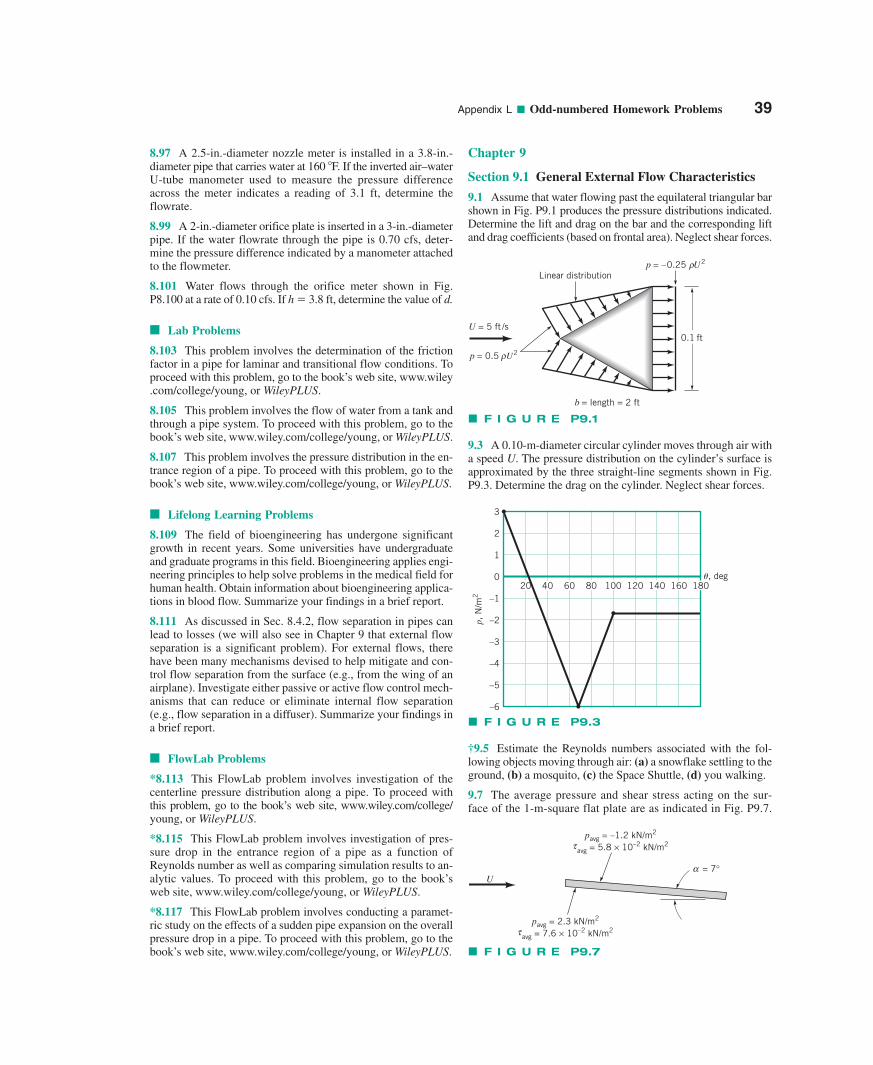
Appendix L ■ Odd-numbered Homework Problems 39
8.97 A 2.5-in.-diameter nozzle meter is installed in a 3.8-in.-diameter pipe that carries water at 160 F. If the inverted air–waterU-tube manometer used to measure the pressure differenceacross the meter indicates a reading of 3.1 ft, determine theflowrate.
8.99 A 2-in.-diameter orifice plate is inserted in a 3-in.-diameterpipe. If the water flowrate through the pipe is 0.70 cfs, deter-mine the pressure difference indicated by a manometer attachedto the flowmeter.
8.101 Water flows through the orifice meter shown in Fig.P8.100 at a rate of 0.10 cfs. If h � 3.8 ft, determine the value of d.
■ Lab Problems
8.103 This problem involves the determination of the frictionfactor in a pipe for laminar and transitional flow conditions. Toproceed with this problem, go to the book’s web site, www.wiley.com/college/young, or WileyPLUS.
8.105 This problem involves the flow of water from a tank andthrough a pipe system. To proceed with this problem, go to thebook’s web site, www.wiley.com/college/young, or WileyPLUS.
8.107 This problem involves the pressure distribution in the en-trance region of a pipe. To proceed with this problem, go to thebook’s web site, www.wiley.com/college/young, or WileyPLUS.
■ Lifelong Learning Problems
8.109 The field of bioengineering has undergone significantgrowth in recent years. Some universities have undergraduateand graduate programs in this field. Bioengineering applies engi-neering principles to help solve problems in the medical field forhuman health. Obtain information about bioengineering applica-tions in blood flow. Summarize your findings in a brief report.
8.111 As discussed in Sec. 8.4.2, flow separation in pipes canlead to losses (we will also see in Chapter 9 that external flowseparation is a significant problem). For external flows, therehave been many mechanisms devised to help mitigate and con-trol flow separation from the surface (e.g., from the wing of anairplane). Investigate either passive or active flow control mech-anisms that can reduce or eliminate internal flow separation(e.g., flow separation in a diffuser). Summarize your findings ina brief report.
■ FlowLab Problems
*8.113 This FlowLab problem involves investigation of thecenterline pressure distribution along a pipe. To proceed withthis problem, go to the book’s web site, www.wiley.com/college/young, or WileyPLUS.
*8.115 This FlowLab problem involves investigation of pres-sure drop in the entrance region of a pipe as a function ofReynolds number as well as comparing simulation results to an-alytic values. To proceed with this problem, go to the book’sweb site, www.wiley.com/college/young, or WileyPLUS.
*8.117 This FlowLab problem involves conducting a paramet-ric study on the effects of a sudden pipe expansion on the overallpressure drop in a pipe. To proceed with this problem, go to thebook’s web site, www.wiley.com/college/young, or WileyPLUS.
Chapter 9
Section 9.1 General External Flow Characteristics
9.1 Assume that water flowing past the equilateral triangular barshown in Fig. P9.1 produces the pressure distributions indicated.Determine the lift and drag on the bar and the corresponding liftand drag coefficients (based on frontal area). Neglect shear forces.
9.3 A 0.10-m-diameter circular cylinder moves through air witha speed U. The pressure distribution on the cylinder’s surface isapproximated by the three straight-line segments shown in Fig.P9.3. Determine the drag on the cylinder. Neglect shear forces.
†9.5 Estimate the Reynolds numbers associated with the fol-lowing objects moving through air: (a) a snowflake settling to theground, (b) a mosquito, (c) the Space Shuttle, (d) you walking.
9.7 The average pressure and shear stress acting on the sur-face of the 1-m-square flat plate are as indicated in Fig. P9.7.
p = 0.5 U2
U = 5 ft /s
p = –0.25 U2
b = length = 2 ft
Linear distribution
0.1 ft
ρ
ρ
F I G U R E P9.1
3
2
1
0
–1
–2
–3
–4
–5
–6
4020 8060 120100 160140
p, N
/m2
�, deg180
F I G U R E P9.3
U
pavg = –1.2 kN/m2
avg = 5.8 × 10⁻² kN/m2τ
pavg = 2.3 kN/m2
avg = 7.6 × 10⁻² kN/m2τ
α = 7°
F I G U R E P9.7
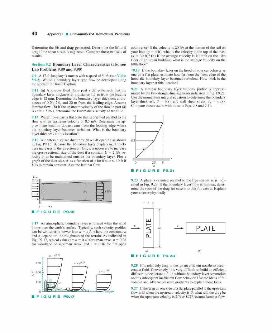
40 Appendix L ■ Odd-numbered Homework Problems
Determine the lift and drag generated. Determine the lift anddrag if the shear stress is neglected. Compare these two sets ofresults.
Section 9.2 Boundary Layer Characteristics (also seeLab Problems 9.89 and 9.90)
9.9 A 17-ft-long kayak moves with a speed of 5 ft/s (see VideoV9.2). Would a boundary layer type flow be developed alongthe sides of the boat? Explain.
9.11 (a) A viscous fluid flows past a flat plate such that theboundary layer thickness at a distance 1.3 m from the leadingedge is 12 mm. Determine the boundary layer thickness at dis-tances of 0.20, 2.0, and 20 m from the leading edge. Assumelaminar flow. (b) If the upstream velocity of the flow in part (a)is U � 1.5 m/s, determine the kinematic viscosity of the fluid.
9.13 Water flows past a flat plate that is oriented parallel to theflow with an upstream velocity of 0.5 m/s. Determine the ap-proximate location downstream from the leading edge wherethe boundary layer becomes turbulent. What is the boundarylayer thickness at this location?
9.15 Air enters a square duct through a 1-ft opening as shownin Fig. P9.15. Because the boundary layer displacement thick-ness increases in the direction of flow, it is necessary to increasethe cross-sectional size of the duct if a constant U � 2 ft/s ve-locity is to be maintained outside the boundary layer. Plot agraph of the duct size, d, as a function of x for 0 � x � 10 ft ifU is to remain constant. Assume laminar flow.
9.17 An atmospheric boundary layer is formed when the windblows over the earth’s surface. Typically, such velocity profilescan be written as a power law: u � ayn, where the constants aand n depend on the roughness of the terrain. As indicated inFig. P9.17, typical values are n � 0.40 for urban areas, n � 0.28for woodland or suburban areas, and n � 0.16 for flat open
country. (a) If the velocity is 20 ft/s at the bottom of the sail onyour boat (y � 4 ft), what is the velocity at the top of the mast(y � 30 ft)? (b) If the average velocity is 10 mph on the 10thfloor of an urban building, what is the average velocity on the60th floor?
†9.19 If the boundary layer on the hood of your car behaves asone on a flat plate, estimate how far from the front edge of thehood the boundary layer becomes turbulent. How thick is theboundary layer at this location?
9.21 A laminar boundary layer velocity profile is approxi-mated by the two straight-line segments indicated in Fig. P9.21.Use the momentum integral equation to determine the boundarylayer thickness, � (x), and wall shear stress, �w � �w(x).Compare these results with those in Eqs. 9.8 and 9.11.
9.23 A plate is oriented parallel to the free stream as is indi-cated in Fig. 9.23. If the boundary layer flow is laminar, deter-mine the ratio of the drag for case a to that for case b. Explainyour answer physically.1 ft d(x) 2 ft/s
U =2 ft/s
x
F I G U R E P9.15
y
δ
δ /2
u
U0 2U___3
F I G U R E P9.21
PLATEU
PLA
TEU4�
�
(a) (b)
F I G U R E P9.23u ~ y0.40
u ~ y0.28
u ~ y0.16
450
300
150
0
y, m
F I G U R E P9.17
9.25 It is relatively easy to design an efficient nozzle to accel-erate a fluid. Conversely, it is very difficult to build an efficientdiffuser to decelerate a fluid without boundary layer separationand its subsequent inefficient flow behavior. Use the ideas of fa-vorable and adverse pressure gradients to explain these facts.
9.27 If the drag on one side of a flat plate parallel to the upstreamflow is when the upstream velocity is U, what will the drag bewhen the upstream velocity is 2U; or U/2? Assume laminar flow.
d
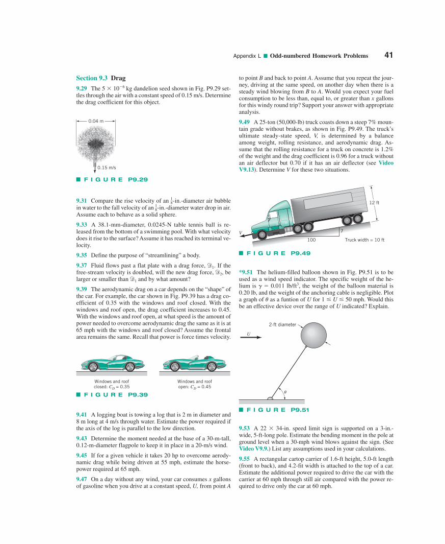
Appendix L ■ Odd-numbered Homework Problems 41
Section 9.3 Drag
9.29 The 5 10�6 kg dandelion seed shown in Fig. P9.29 set-tles through the air with a constant speed of 0.15 m/s. Determinethe drag coefficient for this object.
9.31 Compare the rise velocity of an -in.-diameter air bubble18
in water to the fall velocity of an -in.-diameter water drop in air.18
Assume each to behave as a solid sphere.
9.33 A 38.1-mm-diameter, 0.0245-N table tennis ball is re-leased from the bottom of a swimming pool. With what velocitydoes it rise to the surface? Assume it has reached its terminal ve-locity.
9.35 Define the purpose of “streamlining” a body.
9.37 Fluid flows past a flat plate with a drag force, . If thefree-stream velocity is doubled, will the new drag force, , belarger or smaller than and by what amount?
9.39 The aerodynamic drag on a car depends on the “shape” ofthe car. For example, the car shown in Fig. P9.39 has a drag co-efficient of 0.35 with the windows and roof closed. With thewindows and roof open, the drag coefficient increases to 0.45.With the windows and roof open, at what speed is the amount ofpower needed to overcome aerodynamic drag the same as it is at65 mph with the windows and roof closed? Assume the frontalarea remains the same. Recall that power is force times velocity.
d1
d2
d1
9.41 A logging boat is towing a log that is 2 m in diameter and8 m long at 4 m/s through water. Estimate the power required ifthe axis of the log is parallel to the low direction.
9.43 Determine the moment needed at the base of a 30-m-tall,0.12-m-diameter flagpole to keep it in place in a 20-m/s wind.
9.45 If for a given vehicle it takes 20 hp to overcome aerody-namic drag while being driven at 55 mph, estimate the horse-power required at 65 mph.
9.47 On a day without any wind, your car consumes x gallonsof gasoline when you drive at a constant speed, U, from point A
to point B and back to point A. Assume that you repeat the jour-ney, driving at the same speed, on another day when there is asteady wind blowing from B to A. Would you expect your fuelconsumption to be less than, equal to, or greater than x gallonsfor this windy round trip? Support your answer with appropriateanalysis.
9.49 A 25-ton (50,000-lb) truck coasts down a steep 7% moun-tain grade without brakes, as shown in Fig. P9.49. The truck’sultimate steady-state speed, V, is determined by a balanceamong weight, rolling resistance, and aerodynamic drag. As-sume that the rolling resistance for a truck on concrete is 1.2%of the weight and the drag coefficient is 0.96 for a truck withoutan air deflector but 0.70 if it has an air deflector (see VideoV9.13). Determine V for these two situations.
*9.51 The helium-filled balloon shown in Fig. P9.51 is to beused as a wind speed indicator. The specific weight of the he-lium is � � 0.011 lb/ft3, the weight of the balloon material is0.20 lb, and the weight of the anchoring cable is negligible. Plota graph of � as a funtion of U for 1 � U � 50 mph. Would thisbe an effective device over the range of U indicated? Explain.
9.53 A 22 34-in. speed limit sign is supported on a 3-in.-wide, 5-ft-long pole. Estimate the bending moment in the pole atground level when a 30-mph wind blows against the sign. (SeeVideo V9.9.) List any assumptions used in your calculations.
9.55 A rectangular cartop carrier of 1.6-ft height, 5.0-ft length(front to back), and 4.2-fit width is attached to the top of a car.Estimate the additional power required to drive the car with thecarrier at 60 mph through still air compared with the power re-quired to drive only the car at 60 mph.
0.04 m
0.15 m/s
F I G U R E P9.29
100
7
Truck width = 10 ft
12 ft
V
F I G U R E P9.49
�
U
2-ft diameter
F I G U R E P9.51
Windows and roofclosed: CD = 0.35
Windows and roofopen: CD = 0.45
F I G U R E P9.39
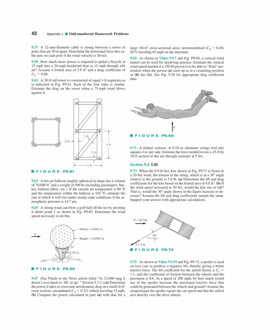
42 Appendix L ■ Odd-numbered Homework Problems
9.57 A 12-mm-diameter cable is strung between a series ofpoles that are 50 m apart. Determine the horizontal force this ca-ble puts on each pole if the wind velocity is 30 m/s.
9.59 How much more power is required to pedal a bicycle at 15 mph into a 20-mph headwind than at 15 mph through stillair? Assume a frontal area of 3.9 ft2 and a drag coefficient of
.
9.61 A 30-ft-tall tower is constructed of equal 1-ft segments asis indicated in Fig. P9.61. Each of the four sides is similar.Estimate the drag on the tower when a 75-mph wind blowsagainst it.
CD � 0.88
9.63 A hot-air balloon roughly spherical in shape has a volumeof 70,000 ft3 and a weight of 500 lb (including passengers, bas-ket, balloon fabric, etc.). If the outside air temperature is 80 Fand the temperature within the balloon is 165 F, estimate therate at which it will rise under steady-state conditions if the at-mospheric pressure is 14.7 psi.
9.65 A strong wind can blow a golf ball off the tee by pivotingit about point 1 as shown in Fig. P9.65. Determine the windspeed necessary to do this.
9.67 (See Fluids in the News article titled “At 12,600 mpg itdoesn’t cost much to ‘fill ’er up,’ ” Section 9.3.3.) (a) Determinethe power it takes to overcome aerodynamic drag on a small (6-ft2
cross section), streamlined (CD � 0.12) vehicle traveling 15 mph.(b) Compare the power calculated in part (a) with that for a
large (36-ft2 cross-sectional area), nonstreamlined (CD � 0.48)SUV traveling 65 mph on the interstate.
9.69 As shown in Video V9.7 and Fig. P9.69, a vertical windtunnel can be used for skydiving practice. Estimate the verticalwind speed needed if a 150-lb person is to be able to “float” mo-tionless when the person (a) curls up as in a crouching positionor (b) lies flat. See Fig. 9.30 for appropriate drag coefficientdata.
9.71 A fishnet consists of 0.10-in.–diameter strings tied intosquares 4 in. per side. Estimate the force needed to tow a 15-ft by30-ft section of this net through seawater at 5 ft/s.
Section 9.4 Lift
9.73 When the 0.9-lb box kite shown in Fig. P9.73 is flown ina 20-ft/s wind, the tension in the string, which is at a 30 anglerelative to the ground, is 3.0 lb. (a) Determine the lift and dragcoefficients for the kite based on the frontal area of 6.0 ft2. (b) Ifthe wind speed increased to 30 ft/s, would the kite rise or fall?That is, would the 30 angle shown in the figure increase or de-crease? Assume the lift and drag coefficients remain the same.Support your answer with appropriate calculations.
9.75 As shown in Video V9.19 and Fig. P9.75, a spoiler is usedon race cars to produce a negative lift, thereby giving a bettertractive force. The lift coefficient for the airfoil shown is CL �1.1, and the coefficient of friction between the wheels and thepavement is 0.6. At a speed of 200 mph, by how much woulduse of the spoiler increase the maximum tractive force thatcould be generated between the wheels and ground? Assume theairspeed past the spoiler equals the car speed and that the airfoilacts directly over the drive wheels.
2 in.
1 in.
1 in.
1 ft
1 ft
F I G U R E P9.61
U
F I G U R E P9.69
U = 20 ft/s
30°
T = 3 lb
F I G U R E P9.730.20 in.
Weight = 0.0992 lb
Radius = 0.845 in.
(1)
U
F I G U R E P9.65
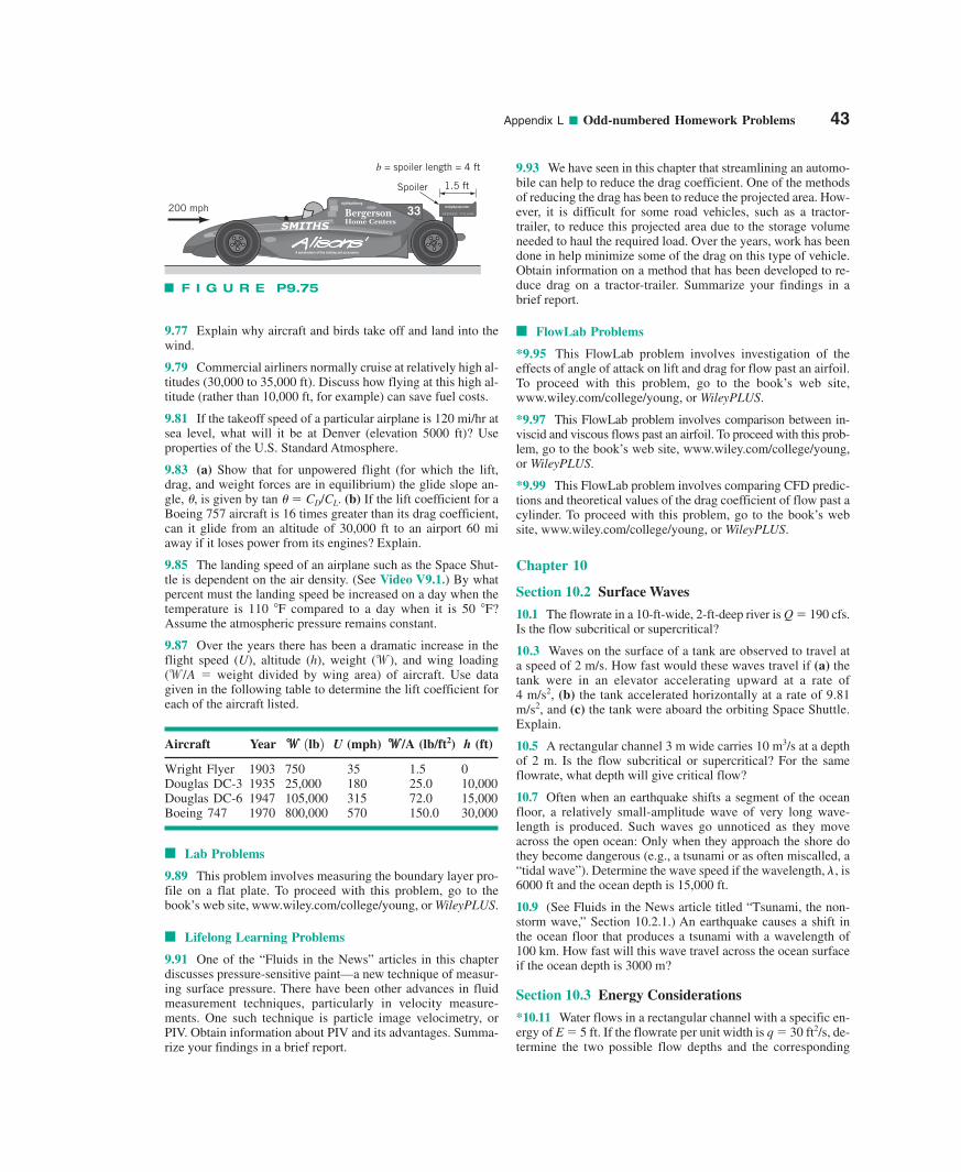
Appendix L ■ Odd-numbered Homework Problems 43
9.77 Explain why aircraft and birds take off and land into thewind.
9.79 Commercial airliners normally cruise at relatively high al-titudes (30,000 to 35,000 ft). Discuss how flying at this high al-titude (rather than 10,000 ft, for example) can save fuel costs.
9.81 If the takeoff speed of a particular airplane is 120 mi/hr atsea level, what will it be at Denver (elevation 5000 ft)? Useproperties of the U.S. Standard Atmosphere.
9.83 (a) Show that for unpowered flight (for which the lift,drag, and weight forces are in equilibrium) the glide slope an-gle, �, is given by tan � � CD/CL. (b) If the lift coefficient for aBoeing 757 aircraft is 16 times greater than its drag coefficient,can it glide from an altitude of 30,000 ft to an airport 60 miaway if it loses power from its engines? Explain.
9.85 The landing speed of an airplane such as the Space Shut-tle is dependent on the air density. (See Video V9.1.) By whatpercent must the landing speed be increased on a day when thetemperature is 110 F compared to a day when it is 50 F?Assume the atmospheric pressure remains constant.
9.87 Over the years there has been a dramatic increase in theflight speed (U), altitude (h), weight ( ), and wing loading( � weight divided by wing area) of aircraft. Use datagiven in the following table to determine the lift coefficient foreach of the aircraft listed.
Aircraft Year ww U (mph) ww/A (lb/ft2) h (ft)
Wright Flyer 1903 750 35 1.5 0Douglas DC-3 1935 25,000 180 25.0 10,000Douglas DC-6 1947 105,000 315 72.0 15,000Boeing 747 1970 800,000 570 150.0 30,000
■ Lab Problems
9.89 This problem involves measuring the boundary layer pro-file on a flat plate. To proceed with this problem, go to thebook’s web site, www.wiley.com/college/young, or WileyPLUS.
■ Lifelong Learning Problems
9.91 One of the “Fluids in the News” articles in this chapterdiscusses pressure-sensitive paint—a new technique of measur-ing surface pressure. There have been other advances in fluidmeasurement techniques, particularly in velocity measure-ments. One such technique is particle image velocimetry, orPIV. Obtain information about PIV and its advantages. Summa-rize your findings in a brief report.
1lb2
w/Aw
9.93 We have seen in this chapter that streamlining an automo-bile can help to reduce the drag coefficient. One of the methodsof reducing the drag has been to reduce the projected area. How-ever, it is difficult for some road vehicles, such as a tractor-trailer, to reduce this projected area due to the storage volumeneeded to haul the required load. Over the years, work has beendone in help minimize some of the drag on this type of vehicle.Obtain information on a method that has been developed to re-duce drag on a tractor-trailer. Summarize your findings in abrief report.
■ FlowLab Problems
*9.95 This FlowLab problem involves investigation of theeffects of angle of attack on lift and drag for flow past an airfoil.To proceed with this problem, go to the book’s web site,www.wiley.com/college/young, or WileyPLUS.
*9.97 This FlowLab problem involves comparison between in-viscid and viscous flows past an airfoil. To proceed with this prob-lem, go to the book’s web site, www.wiley.com/college/young,or WileyPLUS.
*9.99 This FlowLab problem involves comparing CFD predic-tions and theoretical values of the drag coefficient of flow past acylinder. To proceed with this problem, go to the book’s website, www.wiley.com/college/young, or WileyPLUS.
Chapter 10
Section 10.2 Surface Waves
10.1 The flowrate in a 10-ft-wide, 2-ft-deep river is Q � 190 cfs.Is the flow subcritical or supercritical?
10.3 Waves on the surface of a tank are observed to travel ata speed of 2 m/s. How fast would these waves travel if (a) thetank were in an elevator accelerating upward at a rate of 4 m/s2, (b) the tank accelerated horizontally at a rate of 9.81m/s2, and (c) the tank were aboard the orbiting Space Shuttle.Explain.
10.5 A rectangular channel 3 m wide carries 10 m3/s at a depthof 2 m. Is the flow subcritical or supercritical? For the sameflowrate, what depth will give critical flow?
10.7 Often when an earthquake shifts a segment of the oceanfloor, a relatively small-amplitude wave of very long wave-length is produced. Such waves go unnoticed as they moveacross the open ocean: Only when they approach the shore dothey become dangerous (e.g., a tsunami or as often miscalled, a“tidal wave”). Determine the wave speed if the wavelength, �, is6000 ft and the ocean depth is 15,000 ft.
10.9 (See Fluids in the News article titled “Tsunami, the non-storm wave,” Section 10.2.1.) An earthquake causes a shift inthe ocean floor that produces a tsunami with a wavelength of100 km. How fast will this wave travel across the ocean surfaceif the ocean depth is 3000 m?
Section 10.3 Energy Considerations
*10.11 Water flows in a rectangular channel with a specific en-ergy of E � 5 ft. If the flowrate per unit width is q � 30 ft2/s, de-termine the two possible flow depths and the corresponding
akkjbgfkgbsgboiabkv
GOOD YEAR
A manufacturer of fine clothing and accessories
33sfglfbkjxfdbaerg
200 mph
Spoiler 1.5 ft
b = spoiler length = 4 ft
F I G U R E P9.75
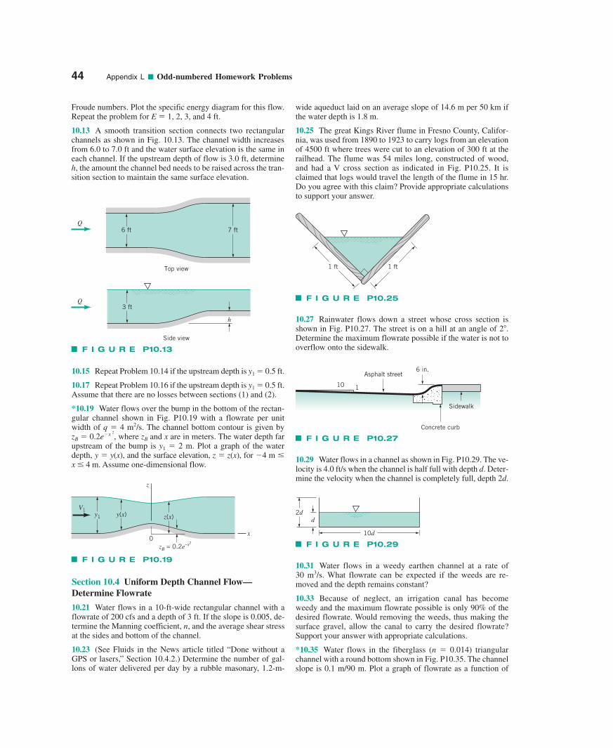
Froude numbers. Plot the specific energy diagram for this flow.Repeat the problem for E � 1, 2, 3, and 4 ft.
10.13 A smooth transition section connects two rectangularchannels as shown in Fig. 10.13. The channel width increasesfrom 6.0 to 7.0 ft and the water surface elevation is the same ineach channel. If the upstream depth of flow is 3.0 ft, determineh, the amount the channel bed needs to be raised across the tran-sition section to maintain the same surface elevation.
10.15 Repeat Problem 10.14 if the upstream depth is y1 � 0.5 ft.
10.17 Repeat Problem 10.16 if the upstream depth is y1 � 0.5 ft.Assume that there are no losses between sections (1) and (2).
*10.19 Water flows over the bump in the bottom of the rectan-gular channel shown in Fig. P10.19 with a flowrate per unitwidth of q � 4 m2/s. The channel bottom contour is given by zB � , where zB and x are in meters. The water depth farupstream of the bump is y1 � 2 m. Plot a graph of the waterdepth, y � y(x), and the surface elevation, z � z(x), for �4 m �x � 4 m. Assume one-dimensional flow.
0.2e�x 2
Section 10.4 Uniform Depth Channel Flow—Determine Flowrate
10.21 Water flows in a 10-ft-wide rectangular channel with aflowrate of 200 cfs and a depth of 3 ft. If the slope is 0.005, de-termine the Manning coefficient, n, and the average shear stressat the sides and bottom of the channel.
10.23 (See Fluids in the News article titled “Done without aGPS or lasers,” Section 10.4.2.) Determine the number of gal-lons of water delivered per day by a rubble masonary, 1.2-m-
wide aqueduct laid on an average slope of 14.6 m per 50 km ifthe water depth is 1.8 m.
10.25 The great Kings River flume in Fresno County, Califor-nia, was used from 1890 to 1923 to carry logs from an elevationof 4500 ft where trees were cut to an elevation of 300 ft at therailhead. The flume was 54 miles long, constructed of wood,and had a V cross section as indicated in Fig. P10.25. It isclaimed that logs would travel the length of the flume in 15 hr.Do you agree with this claim? Provide appropriate calculationsto support your answer.
10.27 Rainwater flows down a street whose cross section isshown in Fig. P10.27. The street is on a hill at an angle of 2.Determine the maximum flowrate possible if the water is not tooverflow onto the sidewalk.
10.29 Water flows in a channel as shown in Fig. P10.29. The ve-locity is 4.0 ft/s when the channel is half full with depth d. Deter-mine the velocity when the channel is completely full, depth 2d.
10.31 Water flows in a weedy earthen channel at a rate of 30 m3/s. What flowrate can be expected if the weeds are re-moved and the depth remains constant?
10.33 Because of neglect, an irrigation canal has becomeweedy and the maximum flowrate possible is only 90% of thedesired flowrate. Would removing the weeds, thus making thesurface gravel, allow the canal to carry the desired flowrate?Support your answer with appropriate calculations.
*10.35 Water flows in the fiberglass (n � 0.014) triangularchannel with a round bottom shown in Fig. P10.35. The channelslope is 0.1 m/90 m. Plot a graph of flowrate as a function of
44 Appendix L ■ Odd-numbered Homework Problems
6 ft 7 ftQ
Q
Top view
Side view
3 ft
h
F I G U R E P10.13
1 ft1 ft
F I G U R E P10.25
Asphalt street6 in.
110
Sidewalk
Concrete curb
F I G U R E P10.27
2dd
10d
F I G U R E P10.290
V1y1
z
x
y(x) z(x)
zB = 0.2e–x2
F I G U R E P10.19
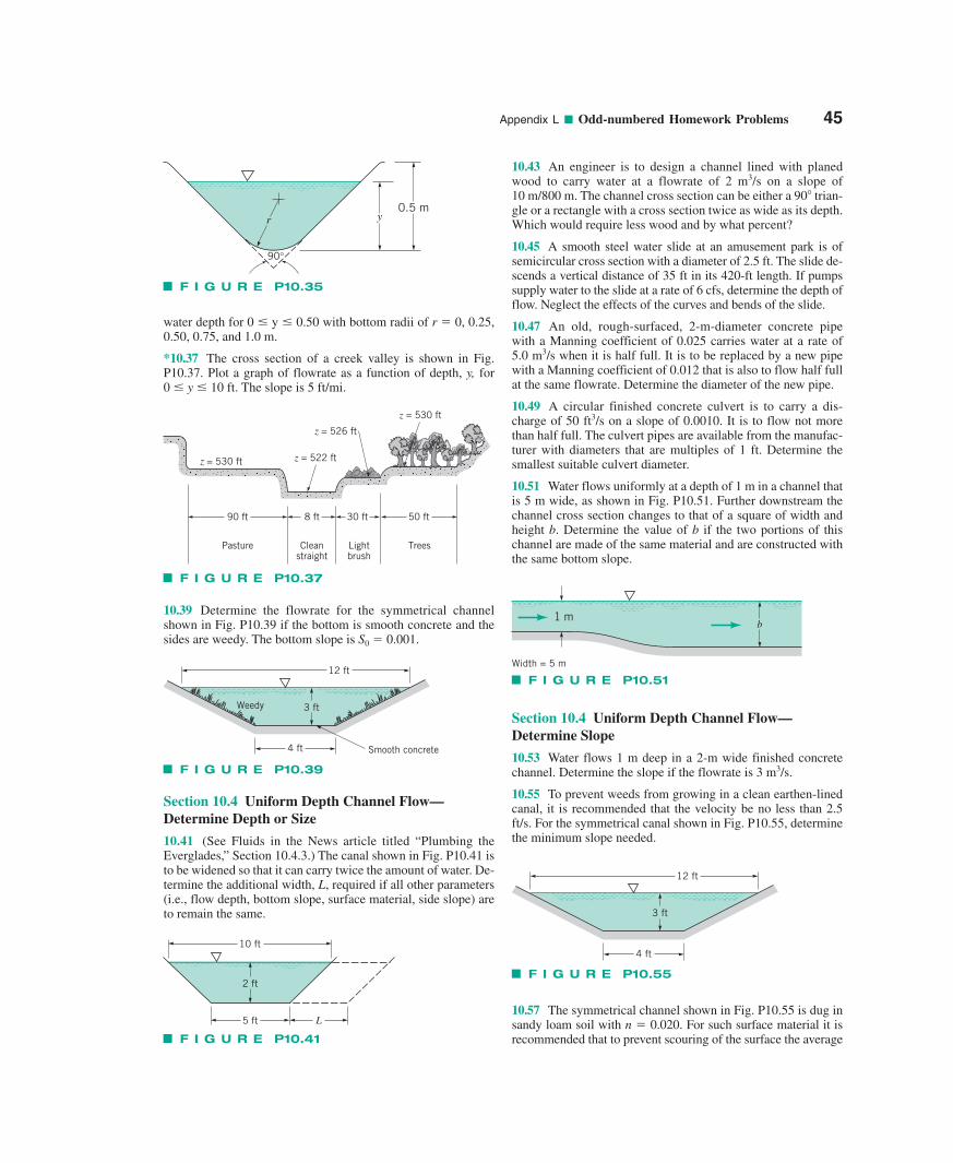
Appendix L ■ Odd-numbered Homework Problems 45
water depth for 0 � y � 0.50 with bottom radii of r � 0, 0.25,0.50, 0.75, and 1.0 m.
*10.37 The cross section of a creek valley is shown in Fig.P10.37. Plot a graph of flowrate as a function of depth, y, for 0 � y � 10 ft. The slope is 5 ft/mi.
10.39 Determine the flowrate for the symmetrical channelshown in Fig. P10.39 if the bottom is smooth concrete and thesides are weedy. The bottom slope is S0 � 0.001.
Section 10.4 Uniform Depth Channel Flow—Determine Depth or Size
10.41 (See Fluids in the News article titled “Plumbing theEverglades,” Section 10.4.3.) The canal shown in Fig. P10.41 isto be widened so that it can carry twice the amount of water. De-termine the additional width, L, required if all other parameters(i.e., flow depth, bottom slope, surface material, side slope) areto remain the same.
Section 10.4 Uniform Depth Channel Flow—Determine Slope
10.53 Water flows 1 m deep in a 2-m wide finished concretechannel. Determine the slope if the flowrate is 3 m3/s.
10.55 To prevent weeds from growing in a clean earthen-linedcanal, it is recommended that the velocity be no less than 2.5ft/s. For the symmetrical canal shown in Fig. P10.55, determinethe minimum slope needed.
10.57 The symmetrical channel shown in Fig. P10.55 is dug insandy loam soil with n � 0.020. For such surface material it isrecommended that to prevent scouring of the surface the average
10.43 An engineer is to design a channel lined with planedwood to carry water at a flowrate of 2 m3/s on a slope of 10 m/800 m. The channel cross section can be either a 90 trian-gle or a rectangle with a cross section twice as wide as its depth.Which would require less wood and by what percent?
10.45 A smooth steel water slide at an amusement park is ofsemicircular cross section with a diameter of 2.5 ft. The slide de-scends a vertical distance of 35 ft in its 420-ft length. If pumpssupply water to the slide at a rate of 6 cfs, determine the depth offlow. Neglect the effects of the curves and bends of the slide.
10.47 An old, rough-surfaced, 2-m-diameter concrete pipewith a Manning coefficient of 0.025 carries water at a rate of 5.0 m3/s when it is half full. It is to be replaced by a new pipewith a Manning coefficient of 0.012 that is also to flow half fullat the same flowrate. Determine the diameter of the new pipe.
10.49 A circular finished concrete culvert is to carry a dis-charge of 50 ft3/s on a slope of 0.0010. It is to flow not morethan half full. The culvert pipes are available from the manufac-turer with diameters that are multiples of 1 ft. Determine thesmallest suitable culvert diameter.
10.51 Water flows uniformly at a depth of 1 m in a channel thatis 5 m wide, as shown in Fig. P10.51. Further downstream thechannel cross section changes to that of a square of width andheight b. Determine the value of b if the two portions of thischannel are made of the same material and are constructed withthe same bottom slope.
yr0.5 m
90°
F I G U R E P10.35
z = 530 ft
90 ft
Pasture Cleanstraight
Lightbrush
Trees
z = 526 ft
z = 530 ft
z = 522 ft
8 ft 30 ft 50 ft
F I G U R E P10.37
1 mb
Width = 5 m
F I G U R E P10.5112 ft
3 ft
4 ft
Weedy
Smooth concrete
F I G U R E P10.39
10 ft
5 ft L
2 ft
F I G U R E P10.41
12 ft
3 ft
4 ft
F I G U R E P10.55
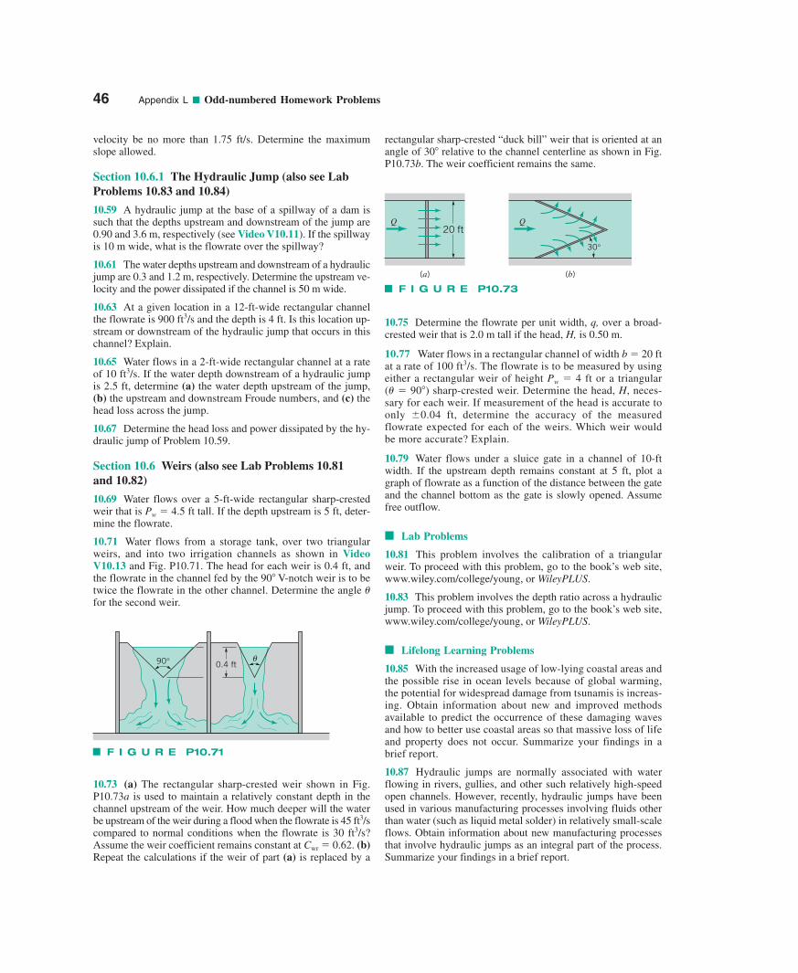
velocity be no more than 1.75 ft/s. Determine the maximumslope allowed.
Section 10.6.1 The Hydraulic Jump (also see LabProblems 10.83 and 10.84)
10.59 A hydraulic jump at the base of a spillway of a dam issuch that the depths upstream and downstream of the jump are0.90 and 3.6 m, respectively (see Video V10.11). If the spillwayis 10 m wide, what is the flowrate over the spillway?
10.61 The water depths upstream and downstream of a hydraulicjump are 0.3 and 1.2 m, respectively. Determine the upstream ve-locity and the power dissipated if the channel is 50 m wide.
10.63 At a given location in a 12-ft-wide rectangular channelthe flowrate is 900 ft3/s and the depth is 4 ft. Is this location up-stream or downstream of the hydraulic jump that occurs in thischannel? Explain.
10.65 Water flows in a 2-ft-wide rectangular channel at a rateof 10 ft3/s. If the water depth downstream of a hydraulic jumpis 2.5 ft, determine (a) the water depth upstream of the jump,(b) the upstream and downstream Froude numbers, and (c) thehead loss across the jump.
10.67 Determine the head loss and power dissipated by the hy-draulic jump of Problem 10.59.
Section 10.6 Weirs (also see Lab Problems 10.81 and 10.82)
10.69 Water flows over a 5-ft-wide rectangular sharp-crestedweir that is Pw � 4.5 ft tall. If the depth upstream is 5 ft, deter-mine the flowrate.
10.71 Water flows from a storage tank, over two triangularweirs, and into two irrigation channels as shown in VideoV10.13 and Fig. P10.71. The head for each weir is 0.4 ft, andthe flowrate in the channel fed by the 90 V-notch weir is to betwice the flowrate in the other channel. Determine the angle �for the second weir.
rectangular sharp-crested “duck bill” weir that is oriented at anangle of 30 relative to the channel centerline as shown in Fig.P10.73b. The weir coefficient remains the same.
10.75 Determine the flowrate per unit width, q, over a broad-crested weir that is 2.0 m tall if the head, H, is 0.50 m.
10.77 Water flows in a rectangular channel of width b � 20 ftat a rate of 100 ft3/s. The flowrate is to be measured by usingeither a rectangular weir of height Pw � 4 ft or a triangular (� � 90) sharp-crested weir. Determine the head, H, neces-sary for each weir. If measurement of the head is accurate toonly �0.04 ft, determine the accuracy of the measuredflowrate expected for each of the weirs. Which weir wouldbe more accurate? Explain.
10.79 Water flows under a sluice gate in a channel of 10-ftwidth. If the upstream depth remains constant at 5 ft, plot agraph of flowrate as a function of the distance between the gateand the channel bottom as the gate is slowly opened. Assumefree outflow.
■ Lab Problems
10.81 This problem involves the calibration of a triangularweir. To proceed with this problem, go to the book’s web site,www.wiley.com/college/young, or WileyPLUS.
10.83 This problem involves the depth ratio across a hydraulicjump. To proceed with this problem, go to the book’s web site,www.wiley.com/college/young, or WileyPLUS.
■ Lifelong Learning Problems
10.85 With the increased usage of low-lying coastal areas andthe possible rise in ocean levels because of global warming,the potential for widespread damage from tsunamis is increas-ing. Obtain information about new and improved methodsavailable to predict the occurrence of these damaging wavesand how to better use coastal areas so that massive loss of lifeand property does not occur. Summarize your findings in abrief report.
10.87 Hydraulic jumps are normally associated with waterflowing in rivers, gullies, and other such relatively high-speedopen channels. However, recently, hydraulic jumps have beenused in various manufacturing processes involving fluids otherthan water (such as liquid metal solder) in relatively small-scaleflows. Obtain information about new manufacturing processesthat involve hydraulic jumps as an integral part of the process.Summarize your findings in a brief report.
46 Appendix L ■ Odd-numbered Homework Problems
90° 0.4 ftθ
F I G U R E P10.71
10.73 (a) The rectangular sharp-crested weir shown in Fig.P10.73a is used to maintain a relatively constant depth in thechannel upstream of the weir. How much deeper will the waterbe upstream of the weir during a flood when the flowrate is 45 ft3/scompared to normal conditions when the flowrate is 30 ft3/s?Assume the weir coefficient remains constant at Cwr � 0.62. (b)Repeat the calculations if the weir of part (a) is replaced by a
(a) (b)
20 ftQ Q
30°
F I G U R E P10.73
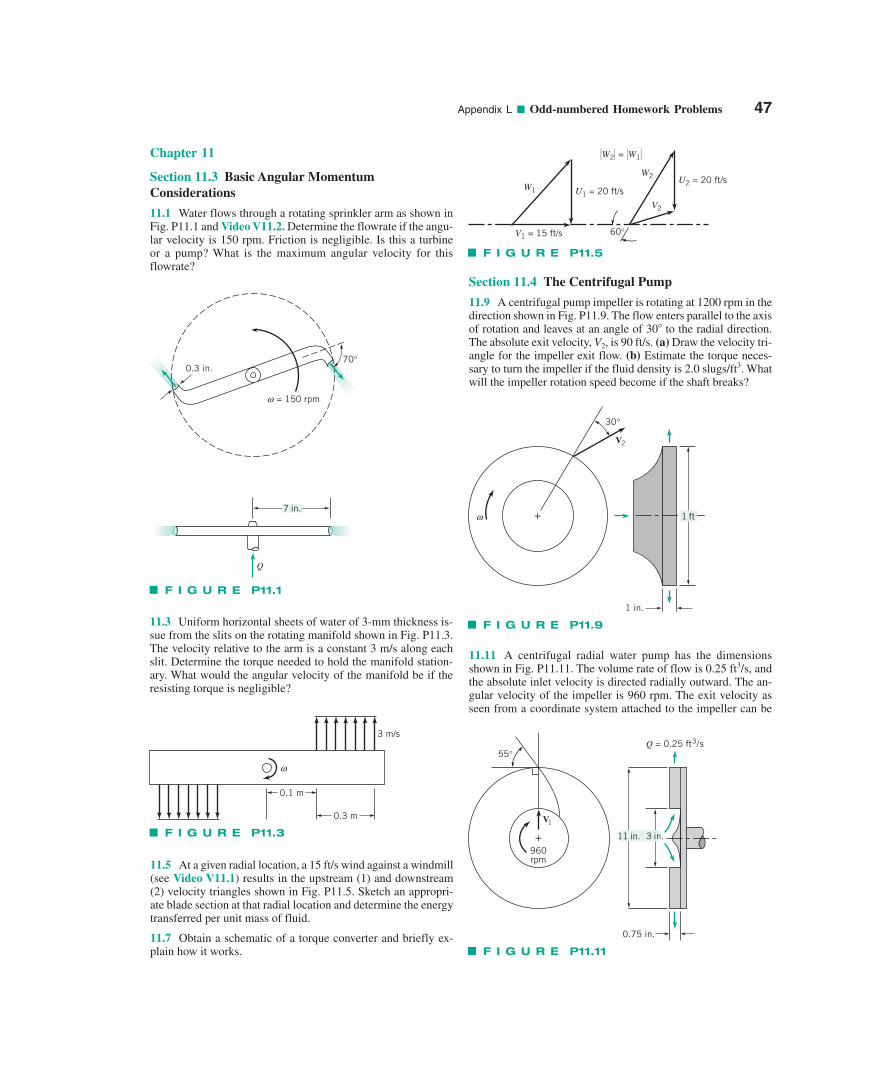
Appendix L ■ Odd-numbered Homework Problems 47
Chapter 11
Section 11.3 Basic Angular MomentumConsiderations
11.1 Water flows through a rotating sprinkler arm as shown inFig. P11.1 and Video V11.2. Determine the flowrate if the angu-lar velocity is 150 rpm. Friction is negligible. Is this a turbine or a pump? What is the maximum angular velocity for thisflowrate?
11.3 Uniform horizontal sheets of water of 3-mm thickness is-sue from the slits on the rotating manifold shown in Fig. P11.3.The velocity relative to the arm is a constant 3 m/s along eachslit. Determine the torque needed to hold the manifold station-ary. What would the angular velocity of the manifold be if theresisting torque is negligible?
11.5 At a given radial location, a 15 ft/s wind against a windmill(see Video V11.1) results in the upstream (1) and downstream(2) velocity triangles shown in Fig. P11.5. Sketch an appropri-ate blade section at that radial location and determine the energytransferred per unit mass of fluid.
11.7 Obtain a schematic of a torque converter and briefly ex-plain how it works.
Section 11.4 The Centrifugal Pump
11.9 A centrifugal pump impeller is rotating at 1200 rpm in thedirection shown in Fig. P11.9. The flow enters parallel to the axisof rotation and leaves at an angle of 30 to the radial direction.The absolute exit velocity, V2, is 90 ft/s. (a) Draw the velocity tri-angle for the impeller exit flow. (b) Estimate the torque neces-sary to turn the impeller if the fluid density is 2.0 slugs/ft3. Whatwill the impeller rotation speed become if the shaft breaks?
11.11 A centrifugal radial water pump has the dimensionsshown in Fig. P11.11. The volume rate of flow is 0.25 ft3/s, andthe absolute inlet velocity is directed radially outward. The an-gular velocity of the impeller is 960 rpm. The exit velocity asseen from a coordinate system attached to the impeller can be
0.3 in.70°
= 150 rpmω
Q
7 in.
F I G U R E P11.1
ω
0.1 m
0.3 m
3 m/s
F I G U R E P11.3
60°
U1 = 20 ft/sU2 = 20 ft/s
W1
�W2� = �W1�
W2
V2
V1 = 15 ft/s
F I G U R E P11.5
+
30°
V2
1 in.
ω 1 ft
F I G U R E P11.9
0.75 in.
55°
960rpm
V1
+
Q = 0.25 ft3/s
11 in. 3 in.
F I G U R E P11.11
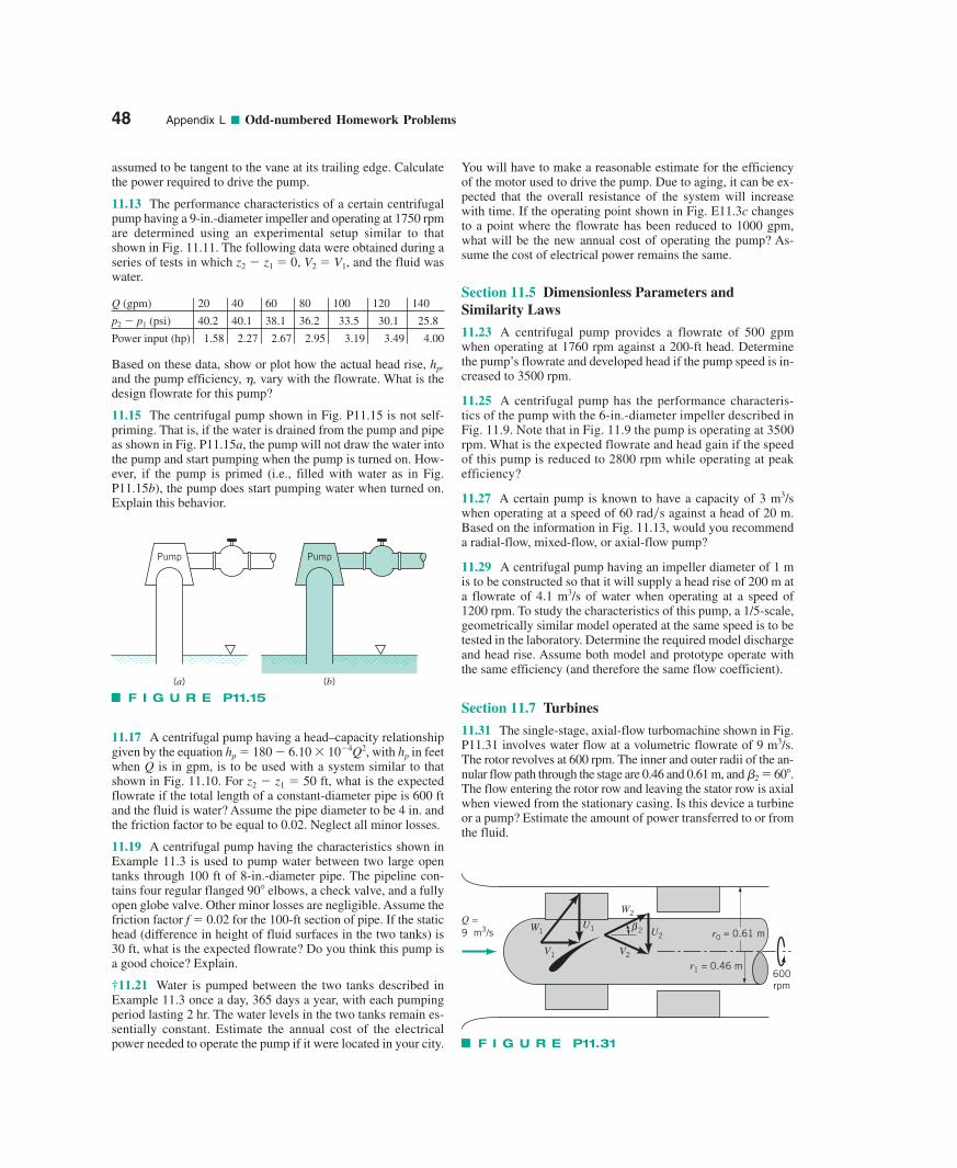
assumed to be tangent to the vane at its trailing edge. Calculatethe power required to drive the pump.
11.13 The performance characteristics of a certain centrifugalpump having a 9-in.-diameter impeller and operating at 1750 rpmare determined using an experimental setup similar to thatshown in Fig. 11.11. The following data were obtained during aseries of tests in which z2 � z1 � 0, V2 � V1, and the fluid waswater.
Q (gpm) 20 40 60 80 100 120 140
p2 � p1 (psi) 40.2 40.1 38.1 36.2 33.5 30.1 25.8
Power input (hp) 1.58 2.27 2.67 2.95 3.19 3.49 4.00
Based on these data, show or plot how the actual head rise, hp,and the pump efficiency, �, vary with the flowrate. What is thedesign flowrate for this pump?
11.15 The centrifugal pump shown in Fig. P11.15 is not self-priming. That is, if the water is drained from the pump and pipeas shown in Fig. P11.15a, the pump will not draw the water intothe pump and start pumping when the pump is turned on. How-ever, if the pump is primed (i.e., filled with water as in Fig.P11.15b), the pump does start pumping water when turned on.Explain this behavior.
11.17 A centrifugal pump having a head–capacity relationshipgiven by the equation hp � 180 � 6.10 10�4Q2, with hp in feetwhen Q is in gpm, is to be used with a system similar to thatshown in Fig. 11.10. For z2 � z1 � 50 ft, what is the expectedflowrate if the total length of a constant-diameter pipe is 600 ftand the fluid is water? Assume the pipe diameter to be 4 in. andthe friction factor to be equal to 0.02. Neglect all minor losses.
11.19 A centrifugal pump having the characteristics shown inExample 11.3 is used to pump water between two large opentanks through 100 ft of 8-in.-diameter pipe. The pipeline con-tains four regular flanged 90 elbows, a check valve, and a fullyopen globe valve. Other minor losses are negligible. Assume thefriction factor f � 0.02 for the 100-ft section of pipe. If the statichead (difference in height of fluid surfaces in the two tanks) is30 ft, what is the expected flowrate? Do you think this pump isa good choice? Explain.
†11.21 Water is pumped between the two tanks described inExample 11.3 once a day, 365 days a year, with each pumpingperiod lasting 2 hr. The water levels in the two tanks remain es-sentially constant. Estimate the annual cost of the electricalpower needed to operate the pump if it were located in your city.
You will have to make a reasonable estimate for the efficiencyof the motor used to drive the pump. Due to aging, it can be ex-pected that the overall resistance of the system will increasewith time. If the operating point shown in Fig. E11.3c changesto a point where the flowrate has been reduced to 1000 gpm,what will be the new annual cost of operating the pump? As-sume the cost of electrical power remains the same.
Section 11.5 Dimensionless Parameters andSimilarity Laws
11.23 A centrifugal pump provides a flowrate of 500 gpmwhen operating at 1760 rpm against a 200-ft head. Determinethe pump’s flowrate and developed head if the pump speed is in-creased to 3500 rpm.
11.25 A centrifugal pump has the performance characteris-tics of the pump with the 6-in.-diameter impeller described inFig. 11.9. Note that in Fig. 11.9 the pump is operating at 3500rpm. What is the expected flowrate and head gain if the speedof this pump is reduced to 2800 rpm while operating at peakefficiency?
11.27 A certain pump is known to have a capacity of 3 m3/swhen operating at a speed of 60 rad�s against a head of 20 m.Based on the information in Fig. 11.13, would you recommenda radial-flow, mixed-flow, or axial-flow pump?
11.29 A centrifugal pump having an impeller diameter of 1 mis to be constructed so that it will supply a head rise of 200 m ata flowrate of 4.1 m3/s of water when operating at a speed of1200 rpm. To study the characteristics of this pump, a 1/5-scale,geometrically similar model operated at the same speed is to betested in the laboratory. Determine the required model dischargeand head rise. Assume both model and prototype operate withthe same efficiency (and therefore the same flow coefficient).
Section 11.7 Turbines
11.31 The single-stage, axial-flow turbomachine shown in Fig.P11.31 involves water flow at a volumetric flowrate of 9 m3/s.The rotor revolves at 600 rpm. The inner and outer radii of the an-nular flow path through the stage are 0.46 and 0.61 m, and �2 � 60.The flow entering the rotor row and leaving the stator row is axialwhen viewed from the stationary casing. Is this device a turbineor a pump? Estimate the amount of power transferred to or fromthe fluid.
48 Appendix L ■ Odd-numbered Homework Problems
Pump Pump
(a) (b)
F I G U R E P11.15
600rpm
r1 = 0.46 m
r0 = 0.61 mQ =9 m3/s
β 2
W2
U2
V2V1
U1W1
F I G U R E P11.31
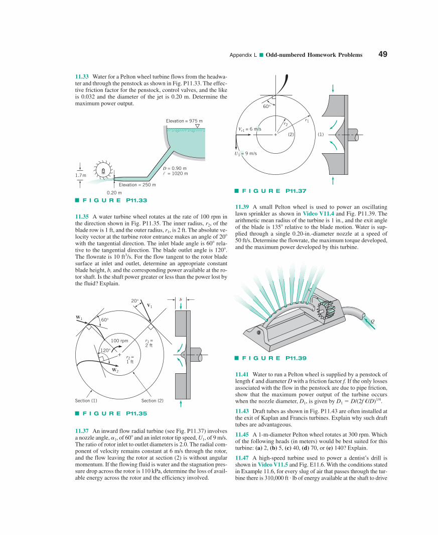
Appendix L ■ Odd-numbered Homework Problems 49
11.33 Water for a Pelton wheel turbine flows from the headwa-ter and through the penstock as shown in Fig. P11.33. The effec-tive friction factor for the penstock, control valves, and the likeis 0.032 and the diameter of the jet is 0.20 m. Determine themaximum power output.
11.35 A water turbine wheel rotates at the rate of 100 rpm inthe direction shown in Fig. P11.35. The inner radius, r2, of theblade row is 1 ft, and the outer radius, r1, is 2 ft. The absolute ve-locity vector at the turbine rotor entrance makes an angle of 20with the tangential direction. The inlet blade angle is 60 rela-tive to the tangential direction. The blade outlet angle is 120.The flowrate is 10 ft3/s. For the flow tangent to the rotor bladesurface at inlet and outlet, determine an appropriate constantblade height, b, and the corresponding power available at the ro-tor shaft. Is the shaft power greater or less than the power lost bythe fluid? Explain.
11.37 An inward flow radial turbine (see Fig. P11.37) involvesa nozzle angle, 1, of 60 and an inlet rotor tip speed, U1, of 9 m/s.The ratio of rotor inlet to outlet diameters is 2.0. The radial com-ponent of velocity remains constant at 6 m/s through the rotor,and the flow leaving the rotor at section (2) is without angularmomentum. If the flowing fluid is water and the stagnation pres-sure drop across the rotor is 110 kPa, determine the loss of avail-able energy across the rotor and the efficiency involved.
11.39 A small Pelton wheel is used to power an oscillatinglawn sprinkler as shown in Video V11.4 and Fig. P11.39. Thearithmetic mean radius of the turbine is 1 in., and the exit angleof the blade is 135 relative to the blade motion. Water is sup-plied through a single 0.20-in.-diameter nozzle at a speed of 50 ft/s. Determine the flowrate, the maximum torque developed,and the maximum power developed by this turbine.
11.41 Water to run a Pelton wheel is supplied by a penstock oflength � and diameter D with a friction factor f. If the only lossesassociated with the flow in the penstock are due to pipe friction,show that the maximum power output of the turbine occurswhen the nozzle diameter, D1, is given by D1 � D/(2f �/D)1/4.
11.43 Draft tubes as shown in Fig. P11.43 are often installed atthe exit of Kaplan and Francis turbines. Explain why such drafttubes are advantageous.
11.45 A 1-m-diameter Pelton wheel rotates at 300 rpm. Whichof the following heads (in meters) would be best suited for thisturbine: (a) 2, (b) 5, (c) 40, (d) 70, or (e) 140? Explain.
11.47 A high-speed turbine used to power a dentist’s drill isshown in Video V11.5 and Fig. E11.6. With the conditions statedin Example 11.6, for every slug of air that passes through the tur-bine there is 310,000 ft . lb of energy available at the shaft to drive
100 rpm
V1
+
20°
r1 =2 ft
60°
120°
W1
W2
r2 =1 ft
Section (2)Section (1)
b
F I G U R E P11.35
Elevation = 975 m
D = 0.90 m = 1020 ml 1.7 m
Elevation = 250 m
0.20 m
F I G U R E P11.33
60°
+
r1r2
(2) (1)
U1 = 9 m/s
Vr1 = 6 m/s
F I G U R E P11.37
Q
F I G U R E P11.39
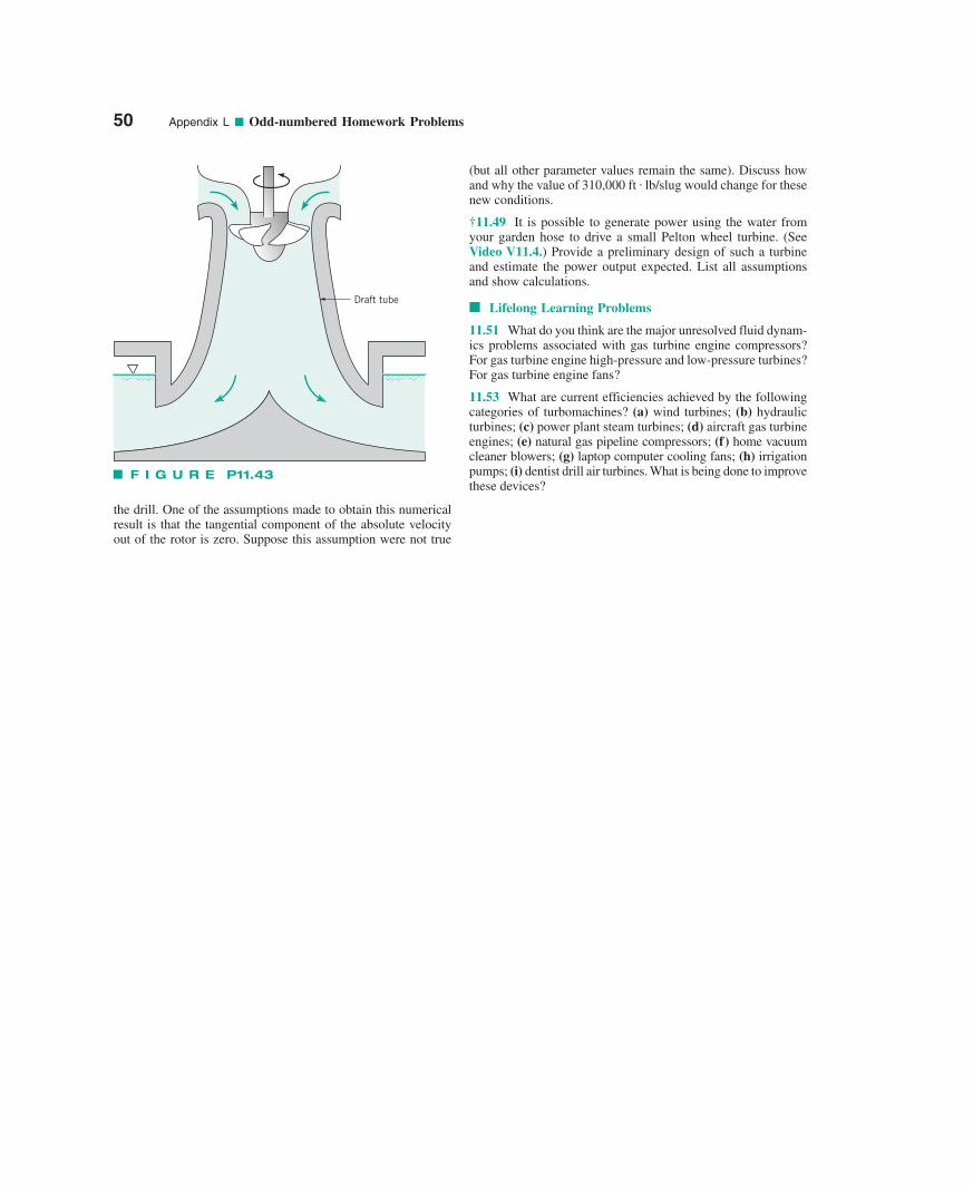
50 Appendix L ■ Odd-numbered Homework Problems
the drill. One of the assumptions made to obtain this numericalresult is that the tangential component of the absolute velocityout of the rotor is zero. Suppose this assumption were not true
(but all other parameter values remain the same). Discuss howand why the value of 310,000 ft . lb/slug would change for thesenew conditions.
†11.49 It is possible to generate power using the water fromyour garden hose to drive a small Pelton wheel turbine. (SeeVideo V11.4.) Provide a preliminary design of such a turbineand estimate the power output expected. List all assumptionsand show calculations.
■ Lifelong Learning Problems
11.51 What do you think are the major unresolved fluid dynam-ics problems associated with gas turbine engine compressors?For gas turbine engine high-pressure and low-pressure turbines?For gas turbine engine fans?
11.53 What are current efficiencies achieved by the followingcategories of turbomachines? (a) wind turbines; (b) hydraulicturbines; (c) power plant steam turbines; (d) aircraft gas turbineengines; (e) natural gas pipeline compressors; (f) home vacuumcleaner blowers; (g) laptop computer cooling fans; (h) irrigationpumps; (i) dentist drill air turbines. What is being done to improvethese devices?
Draft tube
F I G U R E P11.43


![ANSWERS TO ODD-NUMBERED EXERCISES M207 - Ougouagougouag.com/AnsOdds-M207.pdf · 2017-11-27 · Answers to Odd-Numbered Exercises 47. APPENDIX I ANSWERS TO EXERCISES 37. [o, 4] A63](https://img.pdfslide.us/doc/110x75/5ea264aa5c19072f7a5c9a88/answers-to-odd-numbered-exercises-m207-2017-11-27-answers-to-odd-numbered-exercises.jpg)

![Normalized Rare Earth Elements in Water, Sediments, and Wine: … · 2013-12-24 · Rule [26-28], whereby even-numbered elements are more abundant than odd-numbered elements (Figure](https://img.pdfslide.us/doc/110x75/5f38ad1537a1b477d74eddbf/normalized-rare-earth-elements-in-water-sediments-and-wine-2013-12-24-rule.jpg)