Embed Size (px)
Citation preview

APPENDIX IGROUND INVESTIGATION REPORT
Damhead Creek 2 – ES Volume 2June 2009
I.3 2007 – Terra Tek Ltd – Phase 2 Intrusive Site Investigation


SCOTTISHPOWER GENERATION LIMITED
DAMHEAD CREEK POWER STATION
KINGSNORTH, KENT
PROPOSED PHASE II DEVELOPMENT
REPORT ON GROUND INVESTIGATION
Client:
ScottishPower Generation Limited
Consulting Engineers:
PB Power CONTRACT NO: 4660
Westbrook Mills
Godalming Date of Issue: 30 April 2009
Surrey Report Issue: Final
GU7 2AZ Report Type: Interpretative

Damhead Creek Power Station
Kingsnorth, Kent
Proposed Phase ll Development
Report type Interpretative Report issue: Final File number: FSR.4660.02.R Contract number: 4660 Issuing office: Chesham
Originator: .......................................................... FS Russell Graduate
Engineering Geologist
30 April 2009
Checked & approved: .......................................................... WT Gourlay Chief Geotechnical
Engineer 30 April 2009
For and on Behalf of Terra Tek Limited
OPINIONS AND INTERPRETATION EXPRESSED IN THIS DOCUMENT ARE
OUTSIDE THE SCOPE OF UKAS ACCREDITATION
This report is not to be used for contractual or engineering purposes unless the report text and front cover sheet are signed where indicated by both the originator of the report and the approver and the report is designated ‘Final’ on the cover sheet. The report is Confidential. It cannot be assigned without our express approval. We accept no liability to any third party using this report.

Page i of i
TABLE OF CONTENTS
1. INTRODUCTION........................................................................................................1
2. LOCATION OF SITE..................................................................................................2
3. ENVIRONMENTAL SETTING OF SITE ....................................................................2 3.1 GENERAL.................................................................................................................2 3.2 DESCRIPTION OF SITE ..............................................................................................3 3.3 GEOLOGY OF SITE ...................................................................................................3 3.4 CONCEPTUAL SITE MODEL .......................................................................................4
4. GROUND INVESTIGATION ......................................................................................5 4.1 SITE WORK..............................................................................................................5 4.2 LABORATORY TESTING.............................................................................................8
5. GROUND CONDITIONS ENCOUNTERED...............................................................9
6. COMMENTS ON THE RESULTS OF THE INVESTIGATION IN RELATION TO FOUNDATION DESIGN AND CONSTRUCTION............................................................12
7. GEOCHEMICAL CONSIDERATIONS.....................................................................18 7.1 METHODOLOGY......................................................................................................18 7.2 END USER RISK ANALYSIS .....................................................................................19 7.3 GROUNDWATER .....................................................................................................21 7.4 PLANTS .................................................................................................................21 7.5 CHEMICAL ATTACK ON BURIED CONCRETE .............................................................22 7.6 CONSTRUCTION WORKERS.....................................................................................23 7.7 GROUND GAS ........................................................................................................23 7.8 CONCLUSIONS AND CONCEPTUAL SITE MODEL VALIDATION.....................................23
References Total No of Text Pages: 25
Figure APPENDIX A: PLANS
Site Location Plan A1
Site Layout Plan A2
Cross-Section Through Boreholes A3
APPENDIX B: SITE WORKS Notes on Field Procedures
Key to Borehole and Trial Pit Records
Borehole Records (Nos. BH1 to BH8) B1 to B8
Page ii of ii
TABLE OF CONTENTS Cont’d Figure
Trial Pit Records (TP1 to TP6) B9 to B14
Variable Head Permeability Tests B15 to B40
SPT “N” Value vs. Depth Plot B41
Tidal Groundwater Monitoring Results B42
APPENDIX C: GEOTECHNICAL LABORATORY TESTING Notes on Laboratory Procedures
Laboratory Test Results C1 to C73
APPENDIX D: GEOCHEMICAL LABORATORY TESTING
Chemical Contamination Test Results - Soils D1 and D2
Chemical Contamination Tests Results - Water D3 and D4
APPENDIX E: TOPOGRAPHICAL SURVEY Topographical Survey Report E1 to E5
APPENDIX F: SOIL RESISTIVITY TESTING Soil Mechanics Report N7015, dated 07/02/2007 F1
FSR.4660.02.R.doc 1 of 25
SCOTTISHPOWER GENERATION LIMITED
DAMHEAD CREEK POWER STATION KINGSNORTH, KENT
PROPOSED PHASE II DEVELOPMENT
INTERPRETATIVE REPORT ON GROUND INVESTIGATION
Contract No 4660 30 April 2009
1. INTRODUCTION
It is proposed to build Phase ll of a gas fired power station development at
Damhead Creek, Kingsnorth, Kent. On the instructions of PB Power, Consulting
Engineers to ScottishPower Generation Limited, and to their specification, an
investigation was made to provide information on the ground conditions for design
and construction of the proposed works and in relation to any geochemical
contamination of the site. These purposes were significant in determining the scope
of the investigation. No responsibility can be taken for specific design proposals not
detailed or advised at the time of compilation of this report.
A Geoenvironmental Site Assessment was prepared previously by DTS Raeburn,
another company within the Raeburn Group. The results were given in their report
E11996/1, dated November 2006. Information from this desk study has not been
reproduced in this report. None the less, the findings have a bearing on the scope
of the present intrusive investigation, and as such, the two documents should be
read together.
The comments given in this report and any opinions expressed are based on the
ground conditions encountered during the site work and on the results of the
laboratory testing. There may be, however, conditions pertaining to the site which
have not been disclosed by the investigation and which therefore could not be
taken into account.

FSR.4660.02.R.doc 2 of 25
The recommendations of this report are based on an interpretation of legislation,
Codes of Practice, guidance notes and current research opinion. Revision of such,
particularly in environmental matters, is developing rapidly. Although this report
endeavours to anticipate any such changes that may arise within the foreseeable
future, changes are liable to occur which may cause the report inadequately to
address the position at that time. Further, the situation may be subject to varied
interpretation by statutory authorities and others, for which Terra Tek Limited
cannot be responsible.
2. LOCATION OF SITE
The site comprises a triangular area of land that covers approximately 4.3 hectares,
located at National Grid reference 581200, 172850. It is situated on the Hoo
Peninsula, approximately 15km to the north-east of Rochester, in Kent.
The Phase l development lies to the west of the site. The Medway Estuary is
positioned approximately 1km to the south, with Damhead Creek approximately
100m to the south-east. An industrial estate is located to the north-west.
A plan showing the location of the site is given in Figure A1.
3. ENVIRONMENTAL SETTING OF SITE
3.1 General
As noted in section 1, a Geoenvironmental Site Assessment has been prepared
previously by DTS Raeburn, the results of which were given in their report
E11996/1, dated November 2006. Information from this desk study has not been
reproduced in this report. None the less, the findings have a bearing on the scope
of the present intrusive investigation, and as such, the two documents should be
read together.

FSR.4660.02.R.doc 3 of 25
3.2 Description of Site
The triangular site comprises open locally overgrown grassland with occasional
scrub and small bushes. The topography was uneven and hummocky, particularly
in the eastern half. Surface conditions were generally well-drained throughout the
period of site work, with occasional areas of wetter land, causing marshy areas with
reeds to develop. There was no visible evidence of ground contamination.
The site is situated to the east of the existing Damhead Creek Power Station; an
800MW combined cycle gas turbine which was commissioned in 2001. A large
earthed perimeter fence separates the site from the existing Power Station. A one
metre high grassy bund extended along the western site boundary, with other
mounds of reworked earth in the east. The western part of the site is approximately
1.0m to 1.5m higher in elevation than the east and a strong earthed fence with a
lockable gateway separates the two parts.
The environment around the site is rural and predominantly agricultural, with
mitigation schemes in the surrounding area. Kingsnorth Industrial Estate lies
approximately 200m to the north-west. Kingsnorth Power Station lies some 300m
to the south.
Access to the site was along a gravel surfaced road, with a locked gate to prevent
vehicle access. Another lockable fence was situated between the access road and
the site.
3.3 Geology of Site
The Geology of the site as mapped by the British Geological Survey (Ref. 1) Sheet
No. 272 “Chatham”, indicates that the site is underlain in the east and south by
Alluvium (Recent), over London Clay (Eocene). The west and north of the site are
shown to be underlain by Head Brickearth over First Terrace River Gravels
(Recent) over London Clay (Eocene).
FSR.4660.02.R.doc 4 of 25
3.4 Conceptual Site Model
A conceptual site model, drawing together all of the strands of evidence from the
desk study into an overarching characterisation of sources, pathways and receptors
is given in the Phase 1 report. A preliminary risk assessment derived from that
conceptual site model was carried out and reported in the same document. Only
an overview of the conceptual site model and preliminary risk assessment is given
here and for this reason it is important to stress that this document should be read
in conjunction with the desk study site appraisal.
There is no history of development on the site. However, there is evidence of made
ground on the surface, although visual inspection indicated that this was probably
re-deposited natural soil. Pulverised fuel ash is understood to be present in some
parts.
Outside the site, an oil refinery was located to the west and north-west. This has
been replaced with an industrial estate in the north-west and by the Phase l Power
Station in the west. Kingsnorth Power Station is located about 300m to the south.
The conclusions were that collectively, there was the potential for many types of
contamination, and that the likelihood and associated risk was low, low/medium or
medium. Similarly, there was a possible risk of ground gas from any made ground
or organic deposits.
The critical receptors would be staff employed on the site, construction workers,
ground-water and the buildings themselves. The most sensitive end-users would
be female staff. Plants were not considered a particular issue, as the soft
landscaping would be minimal. Groundwater and surface water are both controlled
waters and are therefore protected by law.
The area surrounding the site has also been identified as being a Site of Special
Scientific Interest (SSSI), and a Special Protection Area (SPA). The nearby
shorelines of the River Medway and Damhead Creek have been designated as a
RAMSAR site, signifying a wetland of international importance. These constitute
significant ecological receptors; the closest being approximately 100m away from
the site.

FSR.4660.02.R.doc 5 of 25
Contaminant pathways may include ingestion, inhalation and dermal contact. The
pathways of contamination into the groundwater would be by the leaching of
contaminants by infiltrating surface water and pore water. Groundwater is a
pathway and a receptor for contamination. There are no significant source
protection zones associated with water abstractions near the site. Groundwater is
thought to flow towards the shoreline of Damhead Creek to the south-east of the
site. Damhead Creek is tidal.
To assist in foundation design and construction, eight boreholes were to be sunk by
cable percussion methods. Samples from the boreholes were to be tested to
provide parameters for geotechnical design.
Samples from the boreholes would also be available for geochemical contamination
testing. In addition, samples would be taken from trial pits for both geotechnical
and geochemical contamination testing. A broad analytical suite was proposed
comprising heavy metals, sulphate, pH and petroleum hydrocarbons. Should this
testing highlight any particular problems, then a programme of more specific testing
would be scheduled.
Standpipes were to be installed in some of the boreholes. Monitoring was to be
undertaken for ground-water levels and the generation of ground gas. Ground-
water samples were to be recovered from the standpipes and tested for quality, to
drinking water standards.
4. GROUND INVESTIGATION
4.1 Site Work
The site work was carried out during the period 28th November 2006 to 17th January
2007, in accordance with the guidelines laid down in BS5930 (Ref. 2), BS10175
(Ref. 3) and in-house procedures. The results of the site work are given in
Appendix B.

FSR.4660.02.R.doc 6 of 25
In preparation to the site-works, the smaller wire-bound fence separating the site
from the access road was partially disconnected to allow access to the rigs and
excavator. A mechanical excavator was used to construct a ramp between the two
halves of the site at the lockable gateway, in order for the crews to get their
equipment to the other side of a steep ditch and thereafter to the lower ground on
the other side of the earthed fence. The ground between the borehole positions
was also flattened and smoothed, particularly in the rough and hummocky areas, to
further aid access for the drilling rigs.
Eight boreholes (BH1 to BH8) were sunk by cable percussion methods, and six trial
pits (TP1 to TP6) were excavated by mechanical means, at the positions shown on
the site plan (Fig. A2). The depths of the boreholes and trial pits, the descriptions
of the strata encountered and comments on the ground-water conditions are given
in the borehole and trial pit records (Figs. B1 to B14). The Consulting Engineers
and the Client determined the positions of the boreholes and trial pits. The
positions were set out on site by Glen Surveys Limited as part of a topographic
survey. The borehole depths were determined by the Consulting Engineers, in
conjunction with Terra Tek Limited.
Disturbed and 100mm diameter tube samples were taken at the depths shown on
the borehole and trial pit records, and were despatched to the laboratory at
Chesham for examination and testing. Each sample was uniquely identified and a
transmittal note system used throughout sample transfer.
Falling head permeability tests were carried out at the depths shown on the
borehole records. The results are given in Figures B15 to B40. In this connection,
some of the permeability test results have been reported as zero. This in effect
means that the water level in the borehole did not fall over the test period. A
summary of the tests undertaken is given in the following table:

FSR.4660.02.R.doc 7 of 25
Borehole Depths (m) Figure Numbers BH1 30 B15 BH2 5, 10, 15, 20, 28 B16-B20 BH3 5, 10, 15, 20, 30 B21-B25 BH4 5, 10, 15 B26-B28 BH5 5, 10, 15 B29-B31 BH6 5, 10, 15, 20 B32-B35 BH7 5, 10, 15 B36-B38 BH8 5, 10 B39-B40
Standard (split-barrel sampler and cone) penetration tests (Ref. 4) were undertaken
in the boreholes to assess the relative density or the consistency of the materials
encountered. The values of penetration resistance are given in the borehole
records and a plot of the SPT “N value” vs. depth is provided as Figure B41. The
references to relative density under the heading "Description of Strata" in the
borehole records are based on the field values of penetration resistance
uncorrected for the effects of overburden pressure.
Nominal 50mm diameter perforated standpipes were installed in boreholes BH2,
BH6 and BH8, details of which are given on the relevant records. On 29th January
2007, approximately two weeks after the final drilling date, groundwater monitoring
was undertaken in all three standpipes, over a tidal cycle. The findings are
presented in Figure B42.
After this monitoring took place, all three standpipes were purged. Then water
samples were taken by bailer, before being transferred into one litre glass bottles.
Geochemical samples were transported to the laboratory in coolboxes.
As noted above, a topographical survey was carried out by Glen Surveys Limited.
A copy of the report is included as Appendix E, with the survey transparencies and
AutoCAD files provided separately. As part of this work, the ground levels and co-
ordinates at the borehole and trial pit positions were determined. These are shown
on the records. The ground levels are recorded as metres above ordnance datum,
and the co-ordinates were measured using a local grid.

FSR.4660.02.R.doc 8 of 25
4.2 Laboratory Testing
A test schedule was prepared by Terra Tek Limited. Both the geotechnical and
geochemical testing were carried out at laboratories holding UKAS Accreditation.
The geotechnical laboratory testing was carried out in accordance with BS1377
(Ref. 4). The results are given in Appendix C and comprised the following:
Description of Test Number Figures
Moisture content tests 25 C1
Liquid and plastic limit tests 22 C2 to C23
Particle size distribution tests 20 C24 to C43
Oedometer consolidation tests 10 C44 to C53
Undrained triaxial compression tests 19 C54 to C72
Water soluble sulphate and pH value tests 12 C73
In addition, a suite of chemical contamination tests was carried out on fourteen
samples of soil, and three samples of groundwater. In addition, as part of this work,
the water soluble sulphate contents and pH values of a further five soil samples
were determined. The results of these tests are presented as Figures D1 to D4 in
Appendix D.
With respect to the geochemical soil testing regime, very little made ground was
found on the site. As such, no particular areas of land were targeted. Rather, all
the made ground was tested, together with some of the natural soil.
The resistivity of four soil samples was determined. This work was carried out by
Soil Mechanics Limited and their Test report N7015 is included as Appendix F1.

FSR.4660.02.R.doc 9 of 25
5. GROUND CONDITIONS ENCOUNTERED
A longitudinal section through the site showing the materials encountered in the
boreholes is given in Figure A3. The line along which the section was taken is
shown on the site plan (Fig. A2). It should be recognised that the boreholes have
been projected onto the line of section and this will influence the stratigraphy (e.g.
boreholes BH4 and BH5 lie together on the section, but are at opposite sides of the
site).
The ground conditions are complicated with some of the layers being absent from
some of the boreholes and trial pits. None the less, with the help of the longitudinal
section, the following stratigraphy can be identified. In this connection, immediately
below is a summary, with further detail given thereafter.
TOPSOIL or MADE GROUND Generally encountered to depths
(UNIT 1) ranging from 0.25m to 1.30m, but
locally as much as 1.80m.
Sandy CLAY or sandy gravelly CLAY Encountered to depths ranging from
(UNIT 2) 1.45m to 5.20m. Absent in trial pit
TP4. Trial pits TP2 and TP3 were
completed in this stratum at depths
of 2.90m and 2.70m, respectively.
Clayey or silty SAND and GRAVEL with Encountered to depths ranging
cobbles (in varying proportions) from 4.20m to 6.10m. Absent in
(UNIT 3) boreholes BH2, BH3 and BH5. The
remainder of the trial pits were
completed in this soil at depths of
2.75m to 2.90m.
CLAY or sandy CLAY Encountered to depths ranging from
(UNIT 4) 6.00m to 9.50m. Absent in
boreholes BH4, BH6, BH7 and BH8,
which were sunk at the southern part
of the site.

FSR.4660.02.R.doc 10 of 25
Clayey or silty SAND and GRAVEL with Encountered to depths ranging
cobbles (in varying proportions) from 8.00m to 10.65m.
(UNIT 5)
CLAY or sandy CLAY Encountered to depths ranging from
(UNIT 6) 13.00m to 16.20m. Borehole BH4
was completed in this soil at 15.00m.
Clayey or silty SAND Encountered to depths ranging
(UNIT 7) from 15.00m to 23.00m. Absent in
borehole BH2. Borehole BH5 was
completed in this soil at 15.00m.
Sandy CLAY Encountered to depths ranging from
(UNIT 8) 17.20m to 24.90m. Absent in
borehole BH1.
SAND or clayey or silty SAND Boreholes BH1, BH2, BH3, BH6,
(UNIT 9) BH7 and BH8 were completed in this
stratum at depths between 20.45m
and 30.00m.
UNIT 1 – MADE GROUND
Made ground was encountered only in boreholes BH1, BH2 and BH4 and trial pits
TP1, TP2 and TP3, which were all located at the higher west of the site.
The made ground was commonly up to 1.30m deep, but thicknesses of 1.80m and
1.70m were found in borehole BH4 and trial pit TP2, respectively.
The material generally comprised sandy gravelly clay with broken brick and
concrete. Pulverised fuel ash (pfa) was met in trial pit TP2. Concrete obstructions
were found at some locations.

FSR.4660.02.R.doc 11 of 25
UNIT 2 – Sandy CLAY or sandy gravelly CLAY
This clay was generally firm and stiff. However, soft material was encountered to a
depth of 2.00m in borehole BH7. In addition, very soft pockets were occasionally
noted. However, it is considered that the presence of such pockets will have little
effect on the overall bearing capacity of the ground, since the movement necessary
to allow failure will be restricted by the mass of stronger soil.
In trial pit TP6, the topsoil was separated from the clay by 0.70m of clayey sand.
UNIT 3 – Clayey or silty SAND and GRAVEL
The composition of this granular horizon was extremely variable ranging from an
almost ‘clean’ sandy gravel, to clayey or silty gravelly sand. Occasional cobbles
were present. In addition, at some locations the layer consisted of clayey or silty
sand, with no gravel.
The in situ penetration tests showed the soil to be loose and medium dense.
However, the soil to a depth of 5.00m in borehole BH8 was very loose.
UNIT 4 – CLAY or sandy CLAY
This clay layer was often laminated or contained organic pockets. The consistency
ranged from firm to very stiff, although very soft pockets were occasionally noted.
The argument given above with respect to such pockets also applies in this case.
Very soft to soft organic clay was encountered from 6.65m to 8.20m in borehole
BH1.
UNIT 5 – Clayey or silty SAND and GRAVEL
The composition of this granular horizon ranged from an almost ‘clean’ sandy
gravel, through clayey or silty sand and gravel, to clayey or silty gravelly sand.
Occasional cobbles were present.
The in situ penetration tests showed the soil to be medium dense and dense.
UNIT 6 – CLAY or sandy CLAY
This horizon was laminated in places, fissured in places or contained bands of
sand. The soil was firm, stiff and very stiff.
FSR.4660.02.R.doc 12 of 25
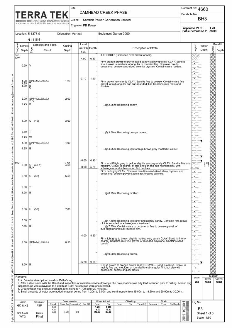
UNIT 7 – Clayey or silty SAND
In places this granular layer contained shells, small pieces of wood or other organic
matter. Sand and gravel with shells was encountered from 17.00m to 17.65m in
borehole BH3.
The in situ penetration tests showed the soil to be medium dense and dense.
UNIT 8 – CLAY or sandy CLAY
Shells were sometimes present within this clay. The soil was firm and stiff.
UNIT 9 – Clayey or silty SAND
This granular horizon occasionally contained bands of clay and small pieces of
wood. However, shells were common.
The soil was medium dense and dense.
Groundwater was encountered in the boreholes at depths ranging from 3.00m to
9.50m, from where the levels rose to between 1.45m and 4.70m over a period of
twenty minutes. Groundwater was also met in trial pit TP5 at a depth of 1.80m, but
was not observed to enter the other pits.
The standpipes in boreholes BH2, BH6 and BH8 recorded standing water levels at
depths of about 1.85m, 1.85m and 1.40m, respectively, on 29 January 2007. The
instruments showed a tidal variation of about 0.10m, with a short time lag.
6. COMMENTS ON THE RESULTS OF THE INVESTIGATION IN RELATION TO FOUNDATION DESIGN AND CONSTRUCTION
It is understood that the new plant will be constructed at the west of the site,
adjacent to that existing. At the time of writing, little information was available on
the proposed foundation loadings. However, it is assumed that they will be heavy.
The natural soils at shallow depth comprise clay which has low or medium
shrinkage potential. As such, conventional pad and strip footings should be placed
at a minimum depth of 0.90m below final ground level.

FSR.4660.02.R.doc 13 of 25
In places the clay at shallow depth is soft. Furthermore, the layer is thin or even
absent in places, and the underlying granular soil is sometimes very loose or loose.
On this basis, conventional pad and strip foundations placed in the natural soils
beneath the topsoil and made ground, at a minimum depth of 0.90m below final
ground level, may be designed to an allowable net bearing pressure of only 40kPa.
This value should ensure the customary acceptable factor of safety of 3 against
shear failure of the ground and with its adoption the maximum total settlement
associated with foundations up to 1.2m wide should be less 25mm. This calculated
settlement allows for submergence of the granular soil.
Settlements in the granular soils will take place largely as the loadings are applied,
whereas those in the clay will be mainly time dependent and will occur over a
considerably longer period. Differential movements will be dependent on variations
in the foundation widths and loading intensities and on the stiffness of the
structures, as well as the ground conditions.
The above quoted value of allowable net bearing pressure will not be able to
accommodate the loadings from the power plant. Furthermore, the poor soil
conditions are present to depths up to about 5.0m. Accordingly, it is considered
that the structures should be supported on pile foundations.
Consideration could be given to the adoption of bored or driven piles in the ground
conditions at this site. Driven piles generally have the advantage of improved
carrying capacity over a similar sized bored pile. This is due to the loosening or
softening of the soils during bored pile shaft formation.
Bored and cast-in-place concrete piles have the advantage that large diameters
can be employed which may be necessary if the loadings are particularly heavy.
However, they will require the use of casings and care will have to be taken during
concreting to avoid necking or waisting of the pile shafts when withdrawing these
liners. Water will be met in the pile holes and care will have to be taken to avoid
removing excess soil when forming the shafts in the sands, as this could lead to
instability of the surrounding ground. It may be necessary to keep the pile holes
topped up with water and to place the concrete by means of a tremmie.

FSR.4660.02.R.doc 14 of 25
Continuous flight auger (c.f.a) piles could be considered, but the above warnings
are emphasised, particularly that of loss of ground, although it is understood that
this can now be closely monitored and corrective measures undertaken.
Steel section piles would also be appropriate, and whilst they have a low area in
end bearing, they have a large surface area, which obviously improves shaft
resistance.
The carrying capacity of an individual pile comprises the end bearing resistance of
the toe, together with the shaft resistance along the embedded length. The
carrying capacity of driven piles is usually evaluated on site using the number of
blows required to reach a certain penetration or set. Indeed, the carrying capacity
is likely to be dictated by the structural strength of the pile concrete. However,
static methods can be used to make a preliminary estimate for both bored and
driven piles and using these methods the following comments on pile capacity are
included.
The ultimate end bearing resistance (Qb) of a bored or driven pile toed in
cohesionless soil is given by:-
Qb = γl g D Nq Ab (kN)
where γl g = average effective unit weight of soil surrounding the pile
(kN/m3)
D = depth to pile toe beneath ground level (m)
Nq = bearing capacity factor which is a function of the angle of
shearing resistance of the soil (φ) and the ratio of pile depth
to diameter as indicated by Berezantsez (Ref. 5). φ is
determined from the results of the standard penetration tests.
The soil in which the piles will be toed will be medium dense
and dense with φ ranging from 30° to 40°. However, in the
case of bored piles, an Nq value appropriate to very loose to
loose soil conditions should always taken (i.e φ = 28° to 30°)
to allow for loosening during shaft formation.
Ab = effective cross-sectional area of base (m2).

FSR.4660.02.R.doc 15 of 25
The ultimate end bearing resistance (Qb) of a bored or driven pile toed in cohesive
soil is given by:-
Qb = cb Nq Ab (kN)
where cb = undrained shear strength of the soil at the toe (kPa)
Nq = bearing capacity factor, generally taken as 9.
The end bearing resistance in granular soil increases with overburden pressure (i.e.
confining pressure) and as such it is generally greater than that for a cohesive soil
at the deeper horizons. Indeed, a cap at 11MN/m2 is usually applied in
calculations. None the less, there is usually advantage in toeing piles in a reliable
thickness of granular soil.
Several methods are available for estimating the ultimate shaft resistance (Qs) of
piles in contact with granular soil. However, that suggested by Broms (Ref. 6) is
readily understandable and is given by:-
Qs = 0.5γI g (D+d) Kstanδ As (kN)
where D = depth to pile toe, or the base of the granular stratum (m)
d = depth to top of the granular stratum (m)
δ = angle of friction between pile and soil (degrees)
Ks = an earth pressure coefficient dependent on the relative
density of the soil. Broms has related values of δ and the
angle of friction (φ) to produce Ks values of 0.5 to 2.0
As = embedded surface area of pile (m2).
For bored piles, δ should be taken as 22° and Ks as 1.0 to allow for loosening
during shaft formation.
The ultimate shaft resistance (Qs) of a pile in cohesive soil is determined by
applying a factor to the undrained shear strength (cu) which exists in the soils along
the embedded length of the pile and is given by:-

FSR.4660.02.R.doc 16 of 25
Qs = α cu As (kN)
where α = 0.45 to 0.5 for bored piles
= 1.0 for driven piles with cu <50kPa
= 0.2 to 1.0 for driven piles with cu >50kPa. The value is
dependent on the ground conditions and depth of
penetration into the stratum.
To obtain the allowable or safe carrying capacity, a factor of safety is applied to the
ultimate value, generally of the order of 2.5.
At this site, many pile types and sized could be designed to accommodate the
working loads, and all cannot be considered in this text. However, the following
table is included as a guide to the loads that could be expected to be carried by
some selected bored and cast-in-place concrete piles. The bearing stratum was
taken as medium dense sand (φ = 36°) at a depth of 25.00m. The ground
conditions were assumed to comprise 5.00m of very loose to loose sand (φ = 28°),
overlying medium dense sand (φ = 33°) to 10.00, underlain by firm clay (cu = 60kPa)
to 20.00m, in turn resting on the medium dense bearing stratum. The groundwater
table was assumed to be at a depth of 2.00m. A factor of safety of 2.5 was allowed
on the ultimate carrying capacity.
Calculations were not carried out for driven piles, because at these depths the
calculated capacity will far exceed the structural strength of the pile. As indicated
earlier, driven piles will achieve their maximum capacity at a much shallower depth.
However, they are limited in diameter which in turn puts a cap on the working load.
Pile Diameter
(mm)
Ultimate End Bearing
Resistance (kN)
Ultimate Shaft
Resistance (kN)
Allowable or Safe Working
Load (kN)
500 700
1000
625 1225 2910
1075 1090 2025
680 1090 2025

FSR.4660.02.R.doc 17 of 25
As noted above, many pile types, sizes and spacings may be selected to carry any
given working load, and the choice should only be made after considering all the
relevant factors. Before a final decision is taken, it would be advisable to consult
specialist piling contractors as to the suitability of their particular piles and
equipment in the conditions at this site, and as to the size of pile and penetrations
they would advise to support the workings loads and to maintain settlements within
acceptable limits.
Lightly loaded reinforced concrete ground bearing floor slabs should be
satisfactory, provided the topsoil and made ground are removed and the slabs are
cast on a blanket of well-compacted imported granular fill. The exposed formation
in any granular soils should be compacted prior to placing the granular blanket, to
make good any disturbance caused during excavation.
However, there will be a risk of excessive settlement with more heavily loaded
floors. The settlement of a floor depends on the loading, the size of the loaded
panel and on the method of construction, as well as the ground conditions. It is
advised that a settlement analysis is carried out for each of the more heavily loaded
floors. At worst, it may be necessary to support these floor slabs on additional
piles.
Continuous support should be provided to the walls of vertically sided foundation
and service excavations which extend below a depth of about 1.2m. Traditional
methods of support could be considered in cohesive soils or granular soils above
the ground-water table. However, where the base of an excavation is in granular
soil beneath the ground-water table, it may not be possible to form the excavation
and install the support. In this case the best option would be interlocking steel
sheeting driven below the base. By driving the sheeting below the base and
thereby lengthening the drainage path, a partial groundwater cut-off would be
provided which would reduce the volumes of water entering the excavation.
Indeed, if the sheeting was driven to a cohesive soil an almost complete cut-off
would be provided.

FSR.4660.02.R.doc 18 of 25
Sump pumping should cope with the volumes of water that enter shallow
excavations. Care should be taken to ensure that pumping operations do not
remove from material from the surrounding ground, thus causing instability. To
prevent the deterioration of prepared foundation formations in the presence of
ground or surface water, it would be advisable to place a blinding layer of concrete,
or the foundation concrete itself, as soon as possible after excavating to formation
level.
7. GEOCHEMICAL CONSIDERATIONS
7.1 Methodology
For the purposes of assessing the geochemical condition of the site, it is now
generally accepted that a risk-based approach should be adopted. A Conceptual
Site Model should be built up from the results of a desk study. The model should
be tested by assessing the risk that a hazard is connected to a potential receptor by
a pathway. The Conceptual Site Model is a requirement of BS10175 (Ref. 3).
Once pollutant linkage has been demonstrated, the risk to each receptor should be
assessed. A tiered approach is advocated in most instances, whereby generic
guidelines are compared against an appropriate data set. If concentrations in
excess of these generic guidelines are found, a further, more detailed but less
conservative site specific risk assessment should be carried out.
For the assessment of human health, the data set has been screened against soil
guideline values derived from the CLEA Model (Refs. 7and 8).
In assessing the risk to ground and surface waters, the results of the analyses are
compared with the drinking water standards (Refs. 9 and 10) and the
Environmental Quality Standards.
As noted earlier, plant growth may not be an issue at this site. However, for
completeness, a section is included. The risk to plant growth (i.e. phytotoxicity) has
been assessed using the Sludge Regulations 1989 (Ref. 11) and the old ICRCL
guidelines (Ref. 12).

FSR.4660.02.R.doc 19 of 25
Sulphate and acid attack on buried concrete should be evaluated with reference to
BRE Special Digest 1 (Ref. 13).
7.2 End User Risk Analysis
The risk to human health from long term exposure to soils has been assessed
using the Contaminated Land Exposure Assessment (CLEA) model (Ref. 7). Prior
to using this and indeed any model, it is necessary to determine whether it is
appropriate and identify aspects that would make the findings more or less
conservative.
The model defines land uses in the following categories: residential with and
without gardens, allotments and commercial/industrial. The proposed development
falls within the commercial/industrial category. CLEA generates soil guideline
values (SGVs) for a variety of determinands, using nationally recognised and
published toxicological data. The SGVs were derived for near neutral soil
conditions (i.e. pH values of 6.0 to 8.0). The average pH was 7.5 at this site, so
that the SGVs are appropriate.
The model also assumes that the data set is representative of an "averaging area".
The averaging area is the area and volume of soil where exposure could occur (i.e.
the landscaped areas). There was no evidence of ground contamination at the site
(indeed there was very little made ground) and as such no specific area has been
targeted. Rather, all the made ground was tested, together with some of the
natural soil.
Fourteen samples of made ground/soil were analysed for a suite comprising
arsenic, boron, cadmium, chromium, copper, lead, mercury, nickel, selenium, zinc,
total petroleum hydrocarbons (TPH), water soluble sulphate and pH. The fourteen
samples were also screened for asbestos.
The range of contamination for the metal contaminants of concern is summarised in
the following table along with respective SGVs.

FSR.4660.02.R.doc 20 of 25
Determinand
Minimum
Concentration
(mg/kg)
Maximum
Concentration
(mg/kg)
SGV
(mg/kg)
Arsenic 5.1 14.6 500
Cadmium <1 <1 1400
Chromium 18 44 5000
Lead 9 83 750
Mercury <0.5 <0.5 480
Selenium <1.0 3.0 8000
Nickel 21 46 5000
The next stage is usually to carry out a statistical analysis by calculating the 95th
percentile of the mean value, as described in CLR 7. Once calculated, it is the
upper 95th percentile that is compared to the relevant SGV. However, the
concentrations of all the metals are so low that this stage is not warranted. Indeed,
it is worth noting that measured concentrations were below the SGVs for the most
onerous of site uses, residential with gardens.
Accordingly, the risk associated with metal contamination is assessed as low.
There is currently no nationally recognised guidance for the assessment of
petroleum hydrocarbons. However, the Environment Agency has consulted on
establishing a framework for doing so. It appears that an approach broadly along
the lines of the Total Petroleum Hydrocarbon Criteria Working Group (TPHCWG) is
proposed. However, the Environment Agency recognises that markers, such as
TPH, can be used for an initial, first tier, screening assessment. A Tier 1 threshold
of 50mg/kg is commonly used, which is the Dutch Target Value.
Total petroleum hydrocarbons (TPH) were generally measured at concentrations of
less than 1mg/kg to 50mg/kg. The 95th percentile of the mean value was 16mg/kg.
As such, the risk associated with hydrocarbon contamination is assessed as low.
The fourteen samples were screened for asbestos. None was found.

FSR.4660.02.R.doc 21 of 25
7.3 Groundwater
Water samples were taken from the standpipes in boreholes BH2, BH6 and BH8.
The water samples were tested for a suite including arsenic, cadmium, chromium,
lead, mercury, selenium, copper, nickel, zinc, phenol, ammoniacal nitrogen,
cyanide (total), pH, TPH and PAH (speciated).
The general accepted practice is to screen these water analysis results against the
drinking water guidelines. The assessment tool employed for the generic screening
of samples for the protection of ‘Controlled Waters’ is the Water Supply (Water
Quality) Regulations 2000, which came into force in December 2000 (Ref. 9).
Where the 2000 guidelines do not apply, the 1989 guidelines (Ref. 10) have been
used as a benchmark. However, some of the determinands are not covered in
either document, and where this is the case, the Environmental Quality Standards
(EQS) have been used as screening values.
When the results were compared with these guidelines, the only determinands
found in excess of the thresholds were TPH and nickel.
Whist the groundwater levels measured in the standpipes showed only a small tidal
variation, there appeared to be a significant change over the period covered by the
whole investigation. As such, the TPH and nickel contamination may well be due to
off-site sources. None the less, at this stage the risk associated with contamination
of the groundwater is assessed as low/medium.
7.4 Plants
Nickel, copper, boron and zinc all exhibit phytotoxic properties, which is to say they
are poisonous to plants at certain concentrations.
Therefore, the Sludge (Use In Agriculture) Regulations (Ref. 11) guidelines have
been utilised for an assessment with respect to phytotoxicity for nickel, copper and
zinc.
The maximum concentrations of nickel, copper and zinc were 46mg/kg, 46mg/kg
and 107mg/kg, respectively. The guideline values are 110mg/kg, 200mg/kg and
450mg/kg.

FSR.4660.02.R.doc 22 of 25
Accordingly, the risk to plants as a result of root uptake is considered to be low for
nickel, copper and zinc.
It has been necessary to fall back on the old ICRCL guidelines (Ref. 12) for an
assessment with respect to the phytotoxicity of boron. The boron (water soluble)
concentrations ranged from less than 1.0mg/kg to 9.8mg/kg. The highest value
was obtained from a sample of pulverised fuel ash (the only one tested). If this
result is removed from the data set, the 95th percentile of the mean becomes
2.9mg/kg. The data set represent a normal distribution and so using the 95th
percentile is appropriate. The old ICRCL trigger threshold was 3mg/kg.
Accordingly, the risk to plants as a result of boron contamination is assessed as
low, provided adequate cover is provided to any pfa.
7.5 Chemical Attack on Buried Concrete
The results of the chemical analyses on thirty-one samples of the made ground/soil
generally indicate soluble sulphate contents (as SO4 in 2:1 water/soil extracts)
between less than 0.01g/l to 0.47g/l. However, there were two elevated values of
1.53g/kg and 1.46g/kg. The 95th percentile of the mean was 0.4g/l. However, the
two elevated values fall outside the normal distribution and therefore represent hot-
spots. The higher concentration was found in a near surface sample of made
ground. However, 1.46g/l was measured in a sample of clay taken from a depth of
14.00m. The associated pH values ranged from 6.3 to 8.6.
BRE Special Digest 1: 2005 (Ref. 13) recommends precautionary measures with
respect to sulphate attack on concrete for a range of concentrations, for both
‘Greenfield’ and ‘Brownfield’ locations. The higher concentrations in the made
ground and natural soil at this site fall within Class DS-2.
Consideration should also be given to the risk of acid attack on concrete. The
classification varies depending upon whether the ground-water is static or mobile.
In the case of both the made ground and natural soils, the classification becomes
DS-2 AC-1s in static conditions and DS-2 AC-1 where the ground-water is mobile.
Provided the concrete mixes are designed in accordance with the above
recommendations, the risk due to sulphate and acid attack is considered low.

FSR.4660.02.R.doc 23 of 25
7.6 Construction Workers
None of the observed concentrations should present a significant risk to the human
health of construction workers, who will experience only short term exposure. None
the less, good standards of site hygiene should always be maintained to ensure
that ingestion and dermal contact are minimised.
7.7 Ground Gas
The generation of methane or carbon dioxide gases is often associated with made
ground or organic deposits. Hydrogen sulphide can be associated with made
ground, particularly material containing slag. The receptors would be operating
staff, construction workers and the buildings themselves.
Assessing the composition of the ground gas was outside the scope of the current
investigation. However, it is likely that the matter will have to be addressed before
construction is allowed to commence.
7.8 Conclusions and Conceptual Site Model Validation
There was no history of any previous development on the site, but there was
evidence of some made ground. The earlier conclusions were that collectively,
there was the potential for many types of contamination, but that the likelihood and
associated risk was low, low/medium or medium. In fact, the only contamination
identified in the boreholes and trial pits was boron contamination in the soils/made
ground, and nickel and petroleum hydrocarbon contamination of the groundwater.
The risk assessment has been updated as follows:

FSR.4660.02.R.doc 24 of 25
Source Pathway Receptor Risk Outcome Action Required
Staff Low No Toxic Metals (from any made ground)
Inhalation, Direct Contact, Ingestion
Humans Construction Worker Low No
Phytotoxic Metals (from any made ground)
Uptake by roots Flora Low See below
Staff Low No Petroleum and Polyaromatic Hydrocarbons (from any made ground)
Inhalation, Direct Contact, Ingestion
Humans Construction Worker Low No
Groundwater Low/Medium See below Leachables and Mobile Hydrocarbons
Migration via permeable strata or ground-water Surface Water Low No
Staff Not Assessed Monitoring
Humans Construction Worker Not Assessed Monitoring
Soil Gases (from any made ground)
Migration via permeable strata
Buildings (fire, explosion) Not Assessed Monitoring
Staff Low No Asbestos (from any made ground)
Inhalation Humans Construction Worker Low No
Buildings and Services Low Specific
concrete mix required
Sulphates and Corrosives (from any made ground)
Direct Contact
Humans Construction Worker Low No
Boron contamination was encountered over the site as a whole. However, by far
the highest concentration was encountered in a sample of pulverised fuel ash (the
only one tested). When this sample is removed from the data set, the 95th
percentile of the mean falls below the threshold with no hot-spots. As such, the risk
to plants as a result of boron contamination is assessed as low, provided adequate
cover is provided to any pfa.
Nickel and petroleum hydrocarbon (TPH) contamination was encountered in the
groundwater. The source may well be off-site. Further sampling and testing is
therefore advised so that the groundwater conditions can be modelled. Fresh
samples should be taken from the standpipes and also from the water courses on
the north-east and southern sides of the site.

FSR.4660.02.R.doc 25 of 25
The standpipes should also be monitored for ground gas. At least three visits
should be made, preferably during periods of low atmospheric pressure when
generation is at its worst.
In the case of sulphate and acid attack on buried concrete, the risk is low only when
the mixes are designed in accordance with BRE Special Digest 1 (Ref. 13) (see
sub-section 7.5).
Graduate Engineering Geologist Chief Geotechnical Engineer
For and on Behalf of Terra Tek Limited
Ground Investigation Department Chesham
This report is not to be used for contractual or engineering purposes unless the report text and front cover sheet is signed where indicated by both the originator of the report and the approver and the report is designated ‘Final’ on the cover sheet.

FSR.4660.02.R.doc 1 of 25
REFERENCES (1) 1:50,000 scale British Geological Survey Map, Sheet No. 272, “Chatham”. (2) BS5930: Code of Practice for Site Investigations, British Standards Institution,
1999. (3) BS10175: Code of Practice for the Investigation of Potentially Contaminated
Sites, British Standards Institution, 2001. (4) BS1377: Methods of Test for Soils for Civil Engineering Purposes, British
Standards Institution, 1990. (5) Berezantsev, V.G. Load Bearing Capacity and Deformation of Piled
Foundations. . Proc. 5th Int. Conf. Soil Mech. Paris 1961. (6) Broms, B. Methods of Calculating the Ultimate Bearing Capacity of Piles-A
Summary. Sols-Soils. 5, 18-19. 1966. (7) R&D Publication CLR7, Assessment of Risks to Human Health from Land
Contamination, DEFRA and the Environment Agency, 2002. (8) R&D Publication CLR10, The Contaminated Land Exposure Assessment Model
(CLEA): Technical Basis and Algorithms, DEFRA and the Environment Agency, 2002.
(9) The Water Supply (Water Quality) Regulations, 2000. (10) Water Supply (Water Quality) Regulations, 1989. (11) Statutory Instrument 1989 No.1263: The Sludge (Use in Agriculture) Regulations
1989. (12) Guidance on the Assessment and Redevelopment of Contaminated Land.
I.C.R.C.L 59/83, Second Edition, 1987. (13) BRE Special Digest 1. Concrete in Aggressive Ground. Building Research
Establishment. 2005.

Site: Contract No:
Client:
Engineer:
Title: Fig No:
A1Not to Scale Sheet 1 of 1
PB Power
Final
4660
WTG
DAMHEAD CREEK PHASE ll
Scottish Power Generation Limited
Chk & App
Originator
FSR
Status
SITE LOCATION PLAN
Crown Copyright Licence Number 1000005786
SITE LOCATION


Contract No:
Title: Fig No:
A2
Sheet 1 of 1
4660
SITE LAYOUT PLAN
FinalWTG
Chk & App
Originator
FSR
Status
Site: DAMHEAD CREEK PHASE ll
Client:
Engineer:
Scottish Power Generation Limited
PB Power
North
Not to Scale
Plan Adapted From Drawing No. S06146-D/1
Line of Cross Section
(See Figure A3)
1350E, 1250N
1650E, 1000N
BH6
BH5
BH1
BH4
BH3
BH2
BH8BH7
TP1
TP6
TP5
TP4TP3
TP2


T
Medium dense to dense dark brown orange slightly clayey sandy GRAVEL.Sand is fine to coarse. Gravel is fine to coarse, of angular to rounded flint.Contains occasional angular to rounded flint cobbles.
...@ 7.25m: Contains cobble-sized pockets of orange brown fine sand.
1.20
2.00
3.00
4.00
5.00
9.50
MADE GROUND: (Brown slightly sandy gravelly CLAY. Sand is fine tocoarse. Gravel is fine to coarse, of angular to rounded flint. Containsoccasional rootlets).
BH1
U
T
B
CPTB
Medium dense to dense dark orange brown very gravelly SAND. Sand isfine to coarse. Gravel is coarse, of angular to rounded flint. Contains cobblesized angular to rounded flint.
# MADE GROUND: (Layer of Road Stone).
1.25
Stiff orange brown sandy gravelly CLAY. Sand is fine to coarse. Gravel isfine to coarse, of angular to rounded flint.
Medium dense orange brown sandy GRAVEL. Sand is fine to coarse.Gravel is fine to coarse, of angular to rounded flint.
...@ 4.00m: Contains cobble-sized pockets of brown sandy clay.
Stiff and very stiff olive brown mottled with orange brown CLAY.
Very soft to soft dark grey slightly organic CLAY.
...@ 7.00m: Becoming light brown in colour.
TOPSOIL: (Grass top over brown sandy slightly gravelly CLAY. Sand is fine.Gravel is fine to coarse, of sub-angular and sub-rounded flint. Containsmany rootlets).0.40
=21
=40
(14)
(64)
=24
8.20 1.45 20
0.50
29/11
=24
2.008.00
2006
6.95 U
2.00
3.00
3.60
4.00
5.00
=25
6.25
=27
7.00
7.25
8.00
8.50
8.75
9.50
1.20
5.25
3.28
B
DRYDRY
1.45
29/11
3.53
2.08
-0.57
-2.57
-4.12
-4.67
3.68
0.55
0.80
2.00
4.65
6.65
8.20
30/11
8.75
W
B, J
SPTTB, J
CPTB
B
8.00
CPTB
SPTTB
T
CPT
6.50
To Depth
Casing
Flush
Struck Rose To Time(mins)
1. # Denotes description based on Driller's log.2. After a discussion with the Client and inspection of available service drawings, the hole position was fully CAT scanned prior to drilling. A hand duginspection pit was excavated to a depth of 1.2m; no services were encountered.3. Groundwater was encountered at 8.20m, rising to 1.45m after 20 minutes.4. Small amounts of water were added to assist boring from 1.20m to 2.00m and continuously from 2.00m to 8.00m.5. Drilling was temporarily suspended on 02/12/2006 after the two sizes of casing were jammed together with sand. The entire casing was removedand replaced before drilling was continued on 03/12/2006.
From
10.0030.00
Final
B1Chk & App
Diam
Cut Off
Ground-water
Equipment:
Sheet 1 of 3
ChisellingDriller
Remarks:
1.202.00
250200
10.5030.00
10.0030.00
1.2030.00
Inspection Pit toCable Percussion to
1.202.00
GD & KS
10.5030.00
2.008.00
1.2030.00
Inspection Pit toCable Percussion to
1.202.00
250200
10.5030.00
10.0030.00
250200
From
WTG
LA
Fig No:
2.008.00
Style: BOREHOLE File: H:\GEOTECHNIC
AL\_GIN
T FILES\4660.G
PJ Printed: 26/03/2007 12:01:37 Terra Tek Lim
ited, 62 R
ochsolloch R
oad, Airdrie, North Lanarkshire, ML6 9BG Tel: 01236-748084 E-m
ail: laboratory@
terratek.fsnet.co.uk
To
Water Added
To Time(hr) Returns Type To Depth
Boring
Scale
Backfill
4660
Inspection Pit toCable Percussion to
Samples and Tests
Depth
Water
Depth
Symbol
1:50
N 1258.8
Borehole No:
Location:
Engineer:
Client:
E 1404.4 Orientation:
PB Power
Dando 2000
Scottish Power Generation Limited
1.2030.00
DAMHEAD CREEK PHASE II
Site: Contract No:
Casing
Vertical
4.08
(mOD)Depth
Originator
Status
Type
Level
Legend
Depth
SampleDescription of Strata
Result
Progress
Depth
4.6/8.10.10.12
3.4/4.5.6.6
2.4/5.6.6.8
3.5/6.6.7.8
3.4/5.6.6.7
2.3/4.6.6.8

17.50
Scottish Power Generation Limited
250200
1.202.00
Inspection Pit toCable Percussion to
1.2030.00
=25
=24
(100)
(80)
(70)
(76)
10.0030.00
18.50
2.008.00
17.00
16.25
16.00
15.50
15.00
14.50
14.00
13.50
13.00
12.50
11.75
11.50
19.25
Client:
2.008.00
Contract No:
10.80
Site:
DAMHEAD CREEK PHASE II
1.2030.00
N 1258.8
Dando 2000VerticalOrientation:
10.5030.00
E 1404.4
17.00
Engineer:
Location:
Borehole No:
Equipment:
BH1
-6.72
14.00
12.50
11.00
10.00
11.00
-11.47
T
4.30
2.45
1/12
16.20
15.55
-12.12
T
...@ 18.50m: Becoming clayey. Contains occasional medium gravel ofrounded flint.
...@ 17.55m: Very thin bed of very stiff light brown slightly sandy clay, withoccasional sub-rounded and rounded black pebbles.
Medium dense dark grey silty SAND. Sand is fine and medium. Containsoccasional fine to coarse gravel-sized fragments of black ancient wood, andoccasional fine and medium gravel-sized shell fragments.
Firm to stiff fissured dark grey brown CLAY. Contains thin beds of slightlysandy CLAY. Sand is fine to coarse.
Stiff fissured dark grey CLAY.
See Previous Page
B
T
15.50
B
U
SPT
B
T
U
T
T
U
T
T
U
B
18.50SPT
Flush
Diam
Chk & App
B1
Final
To Depth
FromCut OffTime(mins)
PB Power
Struck
WTG
1. # Denotes description based on Driller's log.2. After a discussion with the Client and inspection of available service drawings, the hole position was fully CAT scanned prior to drilling. A hand duginspection pit was excavated to a depth of 1.2m; no services were encountered.3. Groundwater was encountered at 8.20m, rising to 1.45m after 20 minutes.4. Small amounts of water were added to assist boring from 1.20m to 2.00m and continuously from 2.00m to 8.00m.5. Drilling was temporarily suspended on 02/12/2006 after the two sizes of casing were jammed together with sand. The entire casing was removedand replaced before drilling was continued on 03/12/2006.
10.0030.00
10.5030.00
250200
1.202.00
Rose To Type
10.0030.00
10.5030.00
250200
1.202.00
Inspection Pit toCable Percussion to
1.2030.00
Style: BOREHOLE File: H:\GEOTECHNIC
AL\_GIN
T FILES\4660.G
PJ Printed: 26/03/2007 12:01:38 Terra Tek Lim
ited, 62 R
ochsolloch R
oad, Airdrie, North Lanarkshire, ML6 9BG Tel: 01236-748084 E-m
ail: laboratory@
terratek.fsnet.co.uk
GD & KS
Boring Casing
To DepthDriller
ReturnsTime(hr)ToFromTo
Scale
2.008.00
Fig No:
LA
Symbol
Level
Remarks:
Progress
Description of StrataSample
Depth
Legend
Result
Samples and Tests
(mOD)Depth
Water
Depth
Backfill
Inspection Pit toCable Percussion to
4660
CasingDepth
Originator
Status
Ground-water Water Added
Sheet 2 of 3
1:50
Chiselling
4.08Depth
Type
3.4/5.6.6.8
2.4/4.6.6.8

22.25
=32
=38
=26
(150)
29.50
29.00
28.50
27.50
27.00
26.00
25.25
24.50
23.00
=42
21.50
21.00
20.50
20.00
29.00
27.50
26.00
24.50
23.00
21.50
E 1404.4
24.00
10.0030.00
Client:
Engineer:
Location: Equipment:
25.25
=36
2.008.00
=40
10.5030.00
250200
1.202.00
Inspection Pit toCable Percussion to
1.2030.00
2.008.00
10.0030.00
10.5030.00
250200
1.202.00
Inspection Pit toCable Percussion to
1.2030.00
END OF BOREHOLE
2.4520.0020.00
-25.92
-23.42
-21.17
3.70
U
30.003/12 30.00
27.50
T
...@ 28.50m: Contains occasional fine and medium gravel-sized shellfragments.
Dense brown grey SAND. Sand is fine and medium. Contains occasionalmedium gravel, of rounded flint.
Dense dark grey clayey SAND. Sand is fine and medium.
...@ 23.00m: No further pockets of clay. Becoming dense.
...@ 22.25m: Contains cobble and gravel-sized pockets of very soft greyclay, with the shell fragments and pebbles arranged in thick and thinlaminations.
...@ 20.00m: Thick bed of firm to stiff light grey sandy clay.
See Previous Page
K
TSPT
T
T
29.50
T
30.00
SPT
B
TSPT
T
TSPT
B
TSPT
T
T
Borehole No:
SPT
Remarks:
OriginatorTime(mins)Rose ToStruck
Flush
1. # Denotes description based on Driller's log.2. After a discussion with the Client and inspection of available service drawings, the hole position was fully CAT scanned prior to drilling. A hand duginspection pit was excavated to a depth of 1.2m; no services were encountered.3. Groundwater was encountered at 8.20m, rising to 1.45m after 20 minutes.4. Small amounts of water were added to assist boring from 1.20m to 2.00m and continuously from 2.00m to 8.00m.5. Drilling was temporarily suspended on 02/12/2006 after the two sizes of casing were jammed together with sand. The entire casing was removedand replaced before drilling was continued on 03/12/2006.
10.0030.00
10.5030.00
250200
1.202.00
From
1:50
BH1
Ground-water
Sheet 3 of 3
Chiselling
To Depth
Water Added Fig No:
Style: BOREHOLE File: H:\GEOTECHNIC
AL\_GIN
T FILES\4660.G
PJ Printed: 26/03/2007 12:01:38 Terra Tek Lim
ited, 62 R
ochsolloch R
oad, Airdrie, North Lanarkshire, ML6 9BG Tel: 01236-748084 E-m
ail: laboratory@
terratek.fsnet.co.uk
GD & KS
Boring
To DepthTypeReturnsTime(hr)ToFromToCut Off
Casing
Final
B1Chk & App
Scale
2.008.00
Driller
WTG
LA
Status
Diam
4660
Symbol
Depth
Water
Depth
Backfill
Inspection Pit toCable Percussion to
Casing
PB Power
Scottish Power Generation Limited
Contract No:Site:
DAMHEAD CREEK PHASE II
1.2030.00
N 1258.8
Dando 2000VerticalOrientation:
Level
4.08Depth
Type
Progress
Depth
Samples and Tests
(mOD)Result
Description of Strata
Legend
Depth
Sample
6.8/8.10.12.12
5.6/6.8.8.10
3.5/5.6.7.8
4.6/8.8.10.12
4.7/8.10.10.12
5.6/8.8.8.12

TOPSOIL: (Grass top over brown sandy sandy gravelly CLAY. Sand ismedium and coarse. Gravel is fine to coarse, of sub-angular andsub-rounded flint. Contains many rootlets).
6.50
5.50
5.00
4.00
3.50
3.00
2.00
1.70
1.20
1.00
0.50
4.00
9.50
Firm grey CLAY.
Site:
Firm and stiff orange brown slightly mottled sandy CLAY. Sand is fine tocoarse. Contains occasional to rare medium and coarse rounded flintpebbles. Contains fine dead red rootlets.
...@ 2.00m: Contains occasional fine gravel-sized black mottling.
Firm and stiff thinly laminated grey mottled with brown orange CLAY.Contains light brown rare dead rootlet channels.
...@ 4.00m: Becomes less mottled.
2.00
...@ 5.50m: Becomes closely fissured, with an increase in mottling.Contains frequent fine dead red rootlet channels.
...@ 8.00m: Becomes sandy. Sand is fine, and dark grey.
Dense brown slightly clayey sandy GRAVEL. Sand is fine to coarse. Gravelis fine to coarse, of angular to sub-rounded flint.
(65)
...@ 4.50m: Contains rare fine and medium gravel-sized spots of orangebrown clay.
DAMHEAD CREEK PHASE II
1.2030.00
8.50
Dando 2000
0.20
Orientation:E 1390.3
Client:
Engineer:
Location:
Borehole No:
Equipment:
8.00
8/12
=12
(75)
=24
(70)
(45 a)
BH2
2006
B
8.50 3.20 20
MADE GROUND: (Brown to grey sandy gravelly CLAY. Sand is fine andmedium. Gravel is medium, of sub-angular to rounded flint, and fine,sub-angular and sub-rounded brick fragments. Contains occasional to rarerootlets).
-4.29
-2.14
1.61
2.91
4.01
DRYDRY
1.30
2.60
6.35
8.50
3.00
0.50
8/12 6.00
J
BU
B, T
T
KU
B, TSPT
T
U
B, TSPT
T
3.00
U 1.50
J
4.755.00
8.00
N 1206.9
Rose ToFSR
WTG
Driller
CasingDiam
Chk & App
B2
Final
To Depth
From
9.0030.00
Remarks:
Vertical
1.20
Cut Off
9.0030.00
Time(mins)
1. # Denotes description based on Driller's log.2. After a discussion with the Client and inspection of available service drawings, the hole position was fully CAT scanned prior to drilling. A hand duginspection pit was excavated to a depth of 1.2m; no services were encountered.3. Groundwater was encountered at 8.50m, rising to 3.20m after 20 minutes.4. Small amounts of water were added to assist boring at the depths indicated.5. A 50mm diameter perforated standpipe was installed to a depth of 12.00m.
Flush
StruckFig No:
200150
8.50
1.2030.00
Inspection Pit toCable Percussion to
1.20
200150
9.0030.00
Style: BOREHOLE File: H:\GEOTECHNIC
AL\_GIN
T FILES\4660.G
PJ Printed: 26/03/2007 12:01:39 Terra Tek Lim
ited, 62 R
ochsolloch R
oad, Airdrie, North Lanarkshire, ML6 9BG Tel: 01236-748084 E-m
ail: laboratory@
terratek.fsnet.co.uk
1.2030.00
Inspection Pit toCable Percussion to
1.20
200150
9.0030.00
9.0030.00
9.0030.00
Returns
8.50
Scale
To From Time(hr) Type To Depth
Boring
DN & AMTo
SymbolCasingSamples and Tests
Result Legend
DepthDepth
SampleDescription of Strata
Progress
Contract No:
Scottish Power Generation Limited
PB Power
4660
Depth
WaterBackfill
Depth
Inspection Pit toCable Percussion to
Ground-waterOriginator
Status
Water Added
Sheet 1 of 3
1:50
Chiselling
Depth
Level
Type (mOD)
4.21
1.2/2.3.3.4
3.4/5.6.6.7

(120 a)
8.50
9.0030.00
9.0030.00
200150
1.20
Inspection Pit toCable Percussion to
8.50
(120)
(120 a)
(125)
(80 a)
(75)
19.00
18.50
17.30
17.00
15.50
15.00
14.50
1.2030.00
Dando 2000
10.65
4660
PB Power
Scottish Power Generation Limited
Contract No:Site:
DAMHEAD CREEK PHASE II
N 1206.9
VerticalOrientation:E 1390.3
Client:
Engineer:
Location:
Borehole No:
Equipment:
BH2
11.50
1.2030.00
-6.44
14.00
15.00
14.00
12.50
11.00
10.00
14.00
17.00
-11.99
18.50
8.303.20
12.00
9/12
16.20
B
11.00
10.00
...@ 19.00m: Contains occasional to rare fine beige gravel-sized shellfragments.
Firm grey to dark grey sandy CLAY. Sand is fine.# Sand bands.
...@ 12.50m: Becomes sandy.
Stiff closely fissured grey blue slightly sandy CLAY. Sand is fine, of possibleselenite crystals.
See Previous Page
T
15.50
W
12.50
U
BU
K
T
U
BU
T
U
K
U
Rose To
CasingDiam
Chk & App
B2
Final
To Depth
From
WTG
Time(mins)FSR
Struck
Flush
1. # Denotes description based on Driller's log.2. After a discussion with the Client and inspection of available service drawings, the hole position was fully CAT scanned prior to drilling. A hand duginspection pit was excavated to a depth of 1.2m; no services were encountered.3. Groundwater was encountered at 8.50m, rising to 3.20m after 20 minutes.4. Small amounts of water were added to assist boring at the depths indicated.5. A 50mm diameter perforated standpipe was installed to a depth of 12.00m.
9.0030.00
9.0030.00
200150
1.20
Inspection Pit toCable Percussion to
Cut Off To Depth
9.0030.00
9.0030.00
200150
1.20
Inspection Pit toCable Percussion to
1.2030.00
Style: BOREHOLE File: H:\GEOTECHNIC
AL\_GIN
T FILES\4660.G
PJ Printed: 26/03/2007 12:01:40 Terra Tek Lim
ited, 62 R
ochsolloch R
oad, Airdrie, North Lanarkshire, ML6 9BG Tel: 01236-748084 E-m
ail: laboratory@
terratek.fsnet.co.uk
DN & AM
DrillerTypeReturnsTime(hr)ToFromTo
Scale
8.50
Fig No:
Boring
Result(mOD)
Level
Depth
Progress
Description of StrataSample
Depth
Remarks:
Depth
Samples and Tests Casing
Symbol
Depth
Water
Depth
Backfill
Legend
Originator Chiselling
1:50
Sheet 2 of 3
Water AddedGround-water
4.21
Status
Type

20.50
...@ 26.50m: Becomes a light grey very sandy clay. Sand is fine to coarse.
=24
=35
>50
=35
(100)
=29
29.50
28.00
26.50
25.00
23.50
1.2030.00
22.00
Inspection Pit toCable Percussion to
20.00
29.50
28.00
26.50
25.00
23.50
20.50
END OF BOREHOLE
Orientation:
22.50
E 1390.3
Client:
Location:
24.90
Equipment:
BH2
=27
...@ 25.00m: Becomes dark grey to black.
8.50
9.0030.00
9.0030.00
200150
1.20
Inspection Pit toCable Percussion to
1.2030.00
8.50
9.0030.00
9.0030.00
200150
1.20
30.00
Medium dense grey to blueish green very clayey SAND. Sand is fine tocoarse. Contains fine beige gravel-sized shell fragments.
-25.79
-22.69
-20.69
17.30
20.108.10
22.00
28.00
12/12
11/12
10/12
30.00
26.90
15.759.25
SPT
Very stiff / very dense light grey to grey very clayey SAND / very sandyCLAY. Sand is fine and medium.
...@ 23.50m: Clay becomes light grey to grey. Sand is medium andcoarse. Contains rare fine beige gravel-sized shell fragments.
...@ 22.50m: Contains a medium to thin bed of light grey to dark grey toblack clayey sand. Sand is fine.
...@ 20.50m: Becomes very sandy.
See Previous Page
B, TSPT
B, K, TSPT
B, TSPT
B, T
B, T
Engineer:
T
U
B, TSPT
K
30.00
25.00
22.00
20.00
SPT
Cut OffTime(mins)Rose ToStruck
Flush
1. # Denotes description based on Driller's log.2. After a discussion with the Client and inspection of available service drawings, the hole position was fully CAT scanned prior to drilling. A hand duginspection pit was excavated to a depth of 1.2m; no services were encountered.3. Groundwater was encountered at 8.50m, rising to 3.20m after 20 minutes.4. Small amounts of water were added to assist boring at the depths indicated.5. A 50mm diameter perforated standpipe was installed to a depth of 12.00m.
9.0030.00
9.0030.00
200150
1.20
Status
Remarks:
Chiselling
1:50
Sheet 3 of 3
Water AddedGround-water
Borehole No:
Vertical
Fig No:
Style: BOREHOLE File: H:\GEOTECHNIC
AL\_GIN
T FILES\4660.G
PJ Printed: 26/03/2007 12:01:40 Terra Tek Lim
ited, 62 R
ochsolloch R
oad, Airdrie, North Lanarkshire, ML6 9BG Tel: 01236-748084 E-m
ail: laboratory@
terratek.fsnet.co.uk
DN & AM
Boring
To DepthTypeReturnsTime(hr)ToFromToFrom
Casing
Final
B2Chk & App
Scale
8.50
Driller
WTG
FSR
To DepthDiam
Backfill
Site:
Originator
Result
Samples and Tests Casing
Symbol
DepthLegend
Depth
DAMHEAD CREEK PHASE II
Inspection Pit toCable Percussion to
4660
PB Power
Scottish Power Generation Limited
Contract No:
Water
4.21Type
1.2030.00
(mOD)
Level
Depth
Progress
Description of StrataSample
Depth
Dando 2000
N 1206.9
Depth
4.5/6.7.7.7
4.5/5.6.6.7
7.8/11.9.8.7
8.9/11.12.14.14
7.8/8.9.9.9
5.6/7.7.7.8
0.50
3.50
1.20
2.00
8.50
1.201.251.30
2.00
2.25
T
4.00
Firm dark grey CLAY. Contains rare fine sand-sized shiny crystals, andoccasional coarse gravel-sized black organic patches.
Location:
# TOPSOIL: (Grass top over brown topsoil).
Firm orange brown to grey mottled sandy slightly gravelly CLAY. Sand isfine. Gravel is medium, of angular to rounded flint. Contains rare tooccasional coarse sand-sized selenite crystals. Contains rare rootlets.
Firm brown very sandy CLAY. Sand is fine to coarse. Contains rare finegravel, of sub-angular and sub-rounded flint. Contains rare roots androotlets.
...@ 2.25m: Becoming sandy.
...@ 3.50m: Becoming orange brown.
Firm to stiff light grey to yellow slightly sandy gravelly CLAY. Sand is fine andmedium. Gravel is coarse, of sub-angular and sub-rounded flint, withsub-angular and sub-rounded flint cobbles.
3.75
...@ 6.25m: Becoming mottled.
...@ 7.50m: Becoming light grey and slightly sandy. Contains rare gravelof fine, rounded to sub-angular claystone. ...@ 7.75m: Contains rare to occasional fine to coarse gravel, ofsub-angular and sub-rounded flint.
Firm light grey to brown slightly mottled very sandy CLAY. Sand is fine tocoarse. Contains rare fine gravel, of rounded claystone. Contains sandbands*.
...@ 9.00m: Becoming brown.
Dense brown to orange brown sandy GRAVEL. Sand is coarse. Gravel ismainly fine and medium, of rounded to sub-angular flint, but also withoccasional coarse angular clasts.
...@ 4.25m: Becoming light orange brown grey mottled in colour.
3.00
=14
4.004.909.50 4.70 20
20065/12
(32)
(40 a)
0.30
5.0018.5030.00
BH3
Equipment:
Borehole No:
7.75
4.00
4.25
5.00
5.50
6.00
6.25
(30)
7.50
SPT8.50
9.50
=15
=12
(42)
=15
7.00
-0.60
-0.90
-4.00
-5.20
4.00
4.50
B
1.20
4.90
5.20
8.30
9.50
3.10
5/12 0.040.15
B, K
U
T
W
SPTT
T, V
U
SPT
U
T
B
U
T
B
B
3.00
4.50
5.50
7.00
B
V
SPTTBV
Final
Flush
Struck Rose To Time(mins) Cut Off FromDriller
1. # Denotes description based on Driller's log.2. After a discussion with the Client and inspection of available service drawings, the hole position was fully CAT scanned prior to drilling. A hand duginspection pit was excavated to a depth of 1.2m; no services were encountered.3. Groundwater was encountered at 9.50m, rising to 4.70m after 20 minutes.4. Small amounts of water were added to assist boring from 1.20m to 5.00m and continuously from 15.00m to 18.50m and 20.00m to 30.00m..
B3Chk & App
Diam
Water Added
To Depth
Sheet 1 of 3
Engineer:
Chiselling
Remarks:
1.2015.0020.00
200 30.00 30.00
WTG
5.0018.5030.00
1.2030.00
Inspection Pit toCable Percussion to
1.2015.0020.00
200
Casing
30.00
1.2030.00
Inspection Pit toCable Percussion to
1.2015.0020.00
200 30.00 30.0030.00
ToFSR
Fig No:
5.0018.5030.00
Scale
Style: BOREHOLE File: H:\GEOTECHNIC
AL\_GIN
T FILES\4660.G
PJ Printed: 26/03/2007 12:01:42 Terra Tek Lim
ited, 62 R
ochsolloch R
oad, Airdrie, North Lanarkshire, ML6 9BG Tel: 01236-748084 E-m
ail: laboratory@
terratek.fsnet.co.uk
FromGD & KS
Time(hr) Returns Type To Depth
Boring
1:50
To
Backfill
Inspection Pit toCable Percussion to
Casing
Scottish Power Generation Limited
Depth
Water
Depth
Symbol
Ground-water
DAMHEAD CREEK PHASE II
Client:
E 1378.9 Orientation:Vertical Dando 2000
4660
1.2030.00
PB Power
Site: Contract No:
N 1115.6
Samples and Tests
Depth
Originator
Status
Sample
Result Legend
Type
Depth4.30
Description of Strata
Progress
Depth
Level
(mOD)
1.2/3.3.4.4
1.2/4.3.4.4
2.2/3.3.3.3
1.2/3.3.4.5
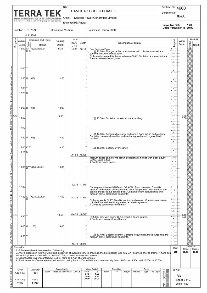
11.50
15.00
16.00
17.50
11.00
12.00
12.25
13.00
13.50
14.00
Location:
10.00
...@ 15.00m: Becomes very sandy.
U
T
See Previous Page ...@ 10.00m: Flint gravel becomes coarse with cobbles, rounded andsub-rounded, with coarse sand.Stiff closely sheared light grey to brown CLAY. Contains rare to occasionalfine sand-sized shiny crystals.
...@ 14.30m: Becomes blue grey and sandy. Sand is fine and medium.Contains occasional rare fine and medium gravel-sized organic blackpatches.
15.25
Medium dense dark grey to brown occasionally mottled with black clayeySAND. Sand is fine.# Contains clayey bands.
Dense grey to brown SAND and GRAVEL. Sand is coarse. Gravel ismedium and coarse, of very rounded black flint pebbles, with medium andcoarse angular to sub-rounded flint. Contains cream coloured fine andmedium gravel-sized shell fragments.
Stiff grey sandy CLAY. Sand is medium and coarse. Contains rare creamcoloured fine and medium gravel-sized shell fragments.# Contains occasional sand bands.
Stiff dark grey very sandy CLAY. Sand is fine to coarse.# Contains occasional sand bands.
...@ 19.40m: Becomes sandy. Contains frequent cream coloured fine andmedium gravel-sized shell fragments.
...@ 13.50m: Contains occasional black mottling.
14.50
30.00 30.00
5.0018.5030.00
1.2015.0020.00
Inspection Pit toCable Percussion to
10.10
5.0018.5030.00
Equipment:
Borehole No:
(60)
16.00
17.00
17.50
18.50
19.00
200
=32
CPT
(64)
(68)
=28
=33
(100)
1.2030.00
19.50
-13.35
T8.653.75
-5.80
-12.70
-14.20
-15.70
-11.20 15.50
17.00
17.65
18.50
20.00
6.306.30
13.506/12
7/12
U
T
U
T
B
U
T
19.00
K, T
B
SPTT
T
BH3
T
B
18.50
B, KCPT 9.35
11.50
13.00
14.50
14.30
Time(mins)
30.001. # Denotes description based on Driller's log.2. After a discussion with the Client and inspection of available service drawings, the hole position was fully CAT scanned prior to drilling. A hand duginspection pit was excavated to a depth of 1.2m; no services were encountered.3. Groundwater was encountered at 9.50m, rising to 4.70m after 20 minutes.4. Small amounts of water were added to assist boring from 1.20m to 5.00m and continuously from 15.00m to 18.50m and 20.00m to 30.00m..
Flush
Chk & App
Rose To
1.2015.0020.00
Cut Off From
To Depth
Final
Struck
Engineer:
Water Added
1:50
Chiselling
30.00200
Remarks:
To Depth
Boring
GD & KS
B3
Time(hr)
1.2030.00
Inspection Pit toCable Percussion to
1.2015.0020.00
200 30.00 30.00
Style: BOREHOLE File: H:\GEOTECHNIC
AL\_GIN
T FILES\4660.G
PJ Printed: 26/03/2007 12:01:42 Terra Tek Lim
ited, 62 R
ochsolloch R
oad, Airdrie, North Lanarkshire, ML6 9BG Tel: 01236-748084 E-m
ail: laboratory@
terratek.fsnet.co.uk
Fig No:
DiamCasing
Driller
WTG
FSRTypeReturns
5.0018.5030.00
Scale
To From To
Ground-water
Depth
4660
Backfill
PB Power
Water
Depth
Symbol
Sheet 2 of 3
Casing
DAMHEAD CREEK PHASE II
Client:
E 1378.9 Orientation:Vertical Dando 2000
Inspection Pit toCable Percussion to
1.2030.00
Samples and Tests
Site: Contract No:
Scottish Power Generation Limited
N 1115.6
Progress
Type
DepthResult(mOD) Depth
4.30
Description of StrataSample
Depth
Legend
Originator
Status
Level
3.4/6.6.8.8
4.6/8.6.8.10
3.4/7.8.8.10

28.75
N 1115.6
1.2015.0020.00
Inspection Pit toCable Percussion to
1.2030.00
=28
=26
=35
=32
=27
=27
=30
30.00
29.50
30.00
28.00
27.50
26.50
26.00
25.00
24.25
23.50
23.00
22.00
21.25
20.50
20.00
29.80
Dando 2000Vertical
30.00
Client:
Engineer:
Location:
Borehole No:
Equipment:
BH3
200
26.50
5.0018.5030.00
30.0030.00200
1.2015.0020.00
Inspection Pit toCable Percussion to
1.2030.00
5.0018.5030.00
TSPT
B
TSPT
B, K
29.4030.00
19.40
23.00
29.50
-25.70
T
5.15
6.353.80
30.0014/12
12/12
T
Orientation:
25.00
23.50
22.00
20.50
END OF BOREHOLE
...@ 28.00m: Becoming medium dense.
...@ 27.50m: Contains occasional to rare fine gravel, of sub-angular tosub-rounded gravel-sized organic and woody fragments.
...@ 25.00m: Becoming dense.
...@ 23.50m: Becomes mottled with black flecks.
...@ 22.00m: Contains occasional shell fragments.
T
K
SPT
SPT
B
TSPT
T
TSPT
T
TSPT
B
28.00
Medium dense dark grey SAND. Sand is fine and medium. Containsoccasional cream coloured fine and medium gravel-sized shell fragments,and occasional firm grey very sandy clay bands.
1.2030.00
Cut OffTime(mins)Rose ToStruck
Flush
1. # Denotes description based on Driller's log.2. After a discussion with the Client and inspection of available service drawings, the hole position was fully CAT scanned prior to drilling. A hand duginspection pit was excavated to a depth of 1.2m; no services were encountered.3. Groundwater was encountered at 9.50m, rising to 4.70m after 20 minutes.4. Small amounts of water were added to assist boring from 1.20m to 5.00m and continuously from 15.00m to 18.50m and 20.00m to 30.00m..
30.0030.00200
To DepthRemarks:
Chiselling
1:50
Sheet 3 of 3
Water AddedGround-water
E 1378.9
1.2015.0020.00
5.0018.5030.00
Style: BOREHOLE File: H:\GEOTECHNIC
AL\_GIN
T FILES\4660.G
PJ Printed: 26/03/2007 12:01:43 Terra Tek Lim
ited, 62 R
ochsolloch R
oad, Airdrie, North Lanarkshire, ML6 9BG Tel: 01236-748084 E-m
ail: laboratory@
terratek.fsnet.co.uk
GD & KS
Boring
To DepthTypeReturnsTime(hr)ToFromFrom
Scale
Fig No:
FSR
WTG
Driller
CasingDiam
Chk & App
B3
Final
To
Result
Samples and Tests Casing
Symbol
Depth
Water
Depth
Backfill
Status
Inspection Pit toCable Percussion to
4660
PB Power
Scottish Power Generation Limited
Contract No:Site:
DAMHEAD CREEK PHASE II
Depth Legend
Type
Depth
Originator
(mOD)Sample
Level
Depth Description of Strata
4.30Progress
4.7/6.8.8.10
4.6/6.7.7.8
5.6/7.8.8.12
3.4/6.6.7.8
3.5/6.6.7.8
4.5/6.6.8.10
4.6/6.6.6.8

CPT
...@ 5.00m: Becoming slightly sandy and slightly clayey. Contains raresub-angular and sub-rounded flint cobbles.
CPTB
B
CPT
B, K
B
CPT
B
TOPSOIL: (Orange brown to grey brown mottled slightly sandy slightlygravelly CLAY. Sand is fine to coarse. Gravel is fine to coarse, of angular tosub-rounded flint. Contains occasional to rare rootlets).
MADE GROUND: (Brown to orange brown mottled silty slightly gravellyCLAY. Gravel is fine and medium, of sub-rounded and rounded flint.Contains abundant black to dark grey concrete boulders throughout).
Firm brown to orange brown slightly sandy CLAY. Sand is fine to coarse.Contains occasional gravel, of fine to coarse, angular to sub-rounded flint.
Loose orange brown to brown very clayey gravelly SAND. Sand is fine tocoarse. Gravel is fine to coarse, of sub-rounded to angular flint.
8.50
B
T
2.00
5.00
B, J
B
U
Medium dense yellow brown to brown slightly clayey SAND and GRAVEL.Sand is coarse. Gravel is fine to coarse, of angular to sub-rounded flint.
SPTT
B
SPTT
B
B
4.00
Medium dense orange brown to brown clayey sandy GRAVEL. Sand iscoarse. Gravel is fine to coarse, of angular to sub-rounded flint. Containsoccasional gravel-sized and cobble-sized pockets of brown sandy clay.
0.50
1.00
2.00
2.50
8.00
3.50
6.50
4.50
5.00
5.50
Final
7.00
1.30
3.00
...@ 6.50m: Sand becomes fine to coarse.
...@ 7.00m: Sand becomes mainly coarse.
Medium dense orange brown to brown very sandy GRAVEL. Sand is fine tocoarse. Gravel is fine to coarse, of sub-rounded to angular flint.
...@ 8.50m: Contains rare to occasional sub-rounded to angular flintcobbles.
...@ 9.50m: Becomes very sandy.9.50
3.00
4.00
5.00
Time(hr) Returns Type To DepthFrom
Boring
ToCC & IA
Style: BOREHOLE File: H:\GEOTECHNIC
AL\_GIN
T FILES\4660.G
PJ Printed: 26/03/2007 12:01:44 Terra Tek Lim
ited, 62 R
ochsolloch R
oad, Airdrie, North Lanarkshire, ML6 9BG Tel: 01236-748084 E-m
ail: laboratory@
terratek.fsnet.co.uk
1.30
1.80
WTG
B4Chk & App
Diam
ToDriller
5.50
FSR
Fig No:
1.30
Scale
Casing
-0.47
-1.47
-3.97
2.60
2.73
5.90
8.008.00
1.43
2.23
14/1
15/1
4.50
Status
1:50
Originator Ground-water Water Added
9.50
4.03Depth
6.50
SampleDescription of Strata
Progress
Depth(mOD)Depth
Type
Chiselling
Level
1.2015.00
Struck Rose To Time(mins) Cut Off From
Sheet 1 of 2
Inspection Pit toCable Percussion to
1.80 0.75
150 15.00 14.50
To Depth
1.80 0.75
Flush
150 15.00 14.501. # Denotes description based on Driller's log.2. After a discussion with the Client and inspection of available service drawings, the hole position was fully CAT scanned prior to drilling. A hand duginspection pit was excavated to a depth of 1.2m; no services were encountered.3. Two earlier attempts at excavating inspection pits were abandoned on concretre obstructions at depths of 0.7m and 1.0m.4. Groundwater was encountered at 4.50m.
Remarks:
DAMHEAD CREEK PHASE II
1.2015.00
Dando 2000Orientation:E 1396.1
Client:
Engineer:
Location:
Borehole No:
Equipment:
BH4
Site:
4.50
(86)
=6
=7
=12
=16
=19
200714/1
N 1039.8
=17
Water
Legend
Result
Samples and Tests Casing
Vertical
DepthDepth
Backfill
Scottish Power Generation Limited
Symbol
Contract No:
PB Power
4660
Inspection Pit toCable Percussion to
4.4/5.5.4.5
1.2/2.1.1.2
1.2/2.2.1.2
2.3/3.2.3.4
4.3/3.4.5.5
3.3/4.3.4.5

0.75
E 1396.1
Client:
Engineer:
Location:
Borehole No:
Equipment:
BH4
14.50
Water
150
Vertical
1.80
Inspection Pit toCable Percussion to
1.2015.00
(135)
=25
(174)
15.00
14.50
13.50
15.00
Scottish Power Generation Limited
Backfill
1.30
Inspection Pit toCable Percussion to
PB Power
Orientation:
Contract No:Site:
DAMHEAD CREEK PHASE II
1.2015.00
N 1039.8
Dando 2000
11.50
4660
13.00
-10.97
-6.67
15.00
10.00
16/1 14.50 15.00
10.70
B
Depth
11.45
10.00
12.90
END OF BOREHOLE
Stiff closely fissured grey to blue grey CLAY. Contains rare to occasional finesand-sized selenite crystals.
See Previous Page ...@ 10.00m: Becomes slightly sandy.
U
12.00
TSPT
B
TU
B, K
14.40
10.90
K, T
Flush
Chk & App
B4
Final
To Depth
FromCut OffTime(mins)
Diam
Struck
1. # Denotes description based on Driller's log.2. After a discussion with the Client and inspection of available service drawings, the hole position was fully CAT scanned prior to drilling. A hand duginspection pit was excavated to a depth of 1.2m; no services were encountered.3. Two earlier attempts at excavating inspection pits were abandoned on concretre obstructions at depths of 0.7m and 1.0m.4. Groundwater was encountered at 4.50m.
14.5015.00150
Depth
Rose To From
Style: BOREHOLE File: H:\GEOTECHNIC
AL\_GIN
T FILES\4660.G
PJ Printed: 26/03/2007 12:01:44 Terra Tek Lim
ited, 62 R
ochsolloch R
oad, Airdrie, North Lanarkshire, ML6 9BG Tel: 01236-748084 E-m
ail: laboratory@
terratek.fsnet.co.uk
CC & IA
Boring
To DepthTypeReturnsTo
Remarks:
To
Scale
1.30
Fig No:
FSR
WTG
Driller
Casing
Time(hr)
Sample
Type
Depth4.03
(mOD)
Level
Depth Description of StrataDepth
Legend
Result
Samples and Tests Casing
Symbol
Progress
Status
1:50
1.80
Sheet 2 of 2
Water AddedGround-water
0.75
ChisellingOriginator
4.5/5.6.7.7
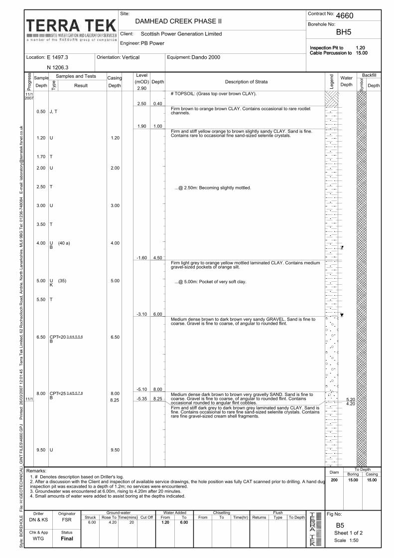
5.00
4.00
3.50
3.00
2.50
2.00
1.70
1.20
0.50
8.00
6.50
1.2015.00
8.00
Firm and stiff dark grey to dark brown grey laminated sandy CLAY. Sand isfine. Contains occasional to rare fine sand-sized selenite crystals. Containsrare fine gravel-sized cream shell fragments.
Medium dense dark brown to brown very gravelly SAND. Sand is fine tocoarse. Gravel is fine to coarse, of angular to rounded flint. Containsoccasional rounded to angular flint cobbles.
Medium dense brown to dark brown very sandy GRAVEL. Sand is fine tocoarse. Gravel is fine to coarse, of angular to rounded flint.
...@ 5.00m: Pocket of very soft clay.
Firm light grey to orange yellow mottled laminated CLAY. Contains mediumgravel-sized pockets of orange silt.
...@ 2.50m: Becoming slightly mottled.
Firm and stiff yellow orange to brown slightly sandy CLAY. Sand is fine.Contains rare to occasional fine sand-sized selenite crystals.
Firm brown to orange brown CLAY. Contains occasional to rare rootletchannels.
# TOPSOIL: (Grass top over brown CLAY).
U
N 1206.3
6.00
Vertical
0.40
E 1497.3
Client:
Engineer:
Location:
Borehole No:
Equipment:
BH5
5.50
6.50
11/12007
6.00 4.20 20
=25
=20
(35)
(40 a)
9.50
B
B -5.35
-5.10
-3.10
-1.60
1.90
2.50
8.25 5.204.20
11/1 8.25
8.00
6.00
4.50
1.00
Dando 2000
CPT
T
KU
BU
T
U
T
U
T
J, T
CPT
9.50
5.00
4.00
3.00
2.00
1.20U
1. # Denotes description based on Driller's log.2. After a discussion with the Client and inspection of available service drawings, the hole position was fully CAT scanned prior to drilling. A hand duginspection pit was excavated to a depth of 1.2m; no services were encountered.3. Groundwater was encountered at 6.00m, rising to 4.20m after 20 minutes.4. Small amounts of water were added to assist boring at the depths indicated.
Chk & App
B5
Final
To Depth
FromCut OffTime(mins)Rose ToStruck
Flush
1:50
Casing
15.0015.00200
1.20
Remarks:
Orientation:
DAMHEAD CREEK PHASE II
Chiselling
Returns
15.0015.00200
1.20
Inspection Pit toCable Percussion to
1.2015.00
Style: BOREHOLE File: H:\GEOTECHNIC
AL\_GIN
T FILES\4660.G
PJ Printed: 26/03/2007 12:01:45 Terra Tek Lim
ited, 62 R
ochsolloch R
oad, Airdrie, North Lanarkshire, ML6 9BG Tel: 01236-748084 E-m
ail: laboratory@
terratek.fsnet.co.uk
DN & KS
BoringDiam
6.00
Driller
WTG
FSRTo Depth
Fig No:Type
Scale
To From To Time(hr)
Result
Sheet 1 of 2
Water
Depth
Symbol
BackfillSamples and Tests
Legend
Depth
Casing
4660Site: Contract No:
Depth
PB Power
Sample
Inspection Pit toCable Percussion to
Scottish Power Generation Limited
Originator
Type
Status
Ground-water Water Added
Level
Description of StrataDepth
2.90
(mOD)
Progress
Depth
3.4/4.5.5.6
3.4/5.5.7.8

Inspection Pit toCable Percussion to
E 1497.3
Client:
Engineer:
Location:
Borehole No:
Equipment:
BH5
Vertical Dando 2000
6.00
15.0015.00200
Depth
PB Power
Depth
13.65
Orientation:
4660
1.2015.00
Scottish Power Generation Limited
Contract No:Site:
DAMHEAD CREEK PHASE II
1.2015.00
N 1206.3
Inspection Pit toCable Percussion to
1.20
12.50
11.00
10.00
15.00
U
-10.75
B
15.0012/1 15.00-12.10END OF BOREHOLE
=21
(a)
15.00
14.00
13.00
12.50
11.00
10.00
14.00
K, T
Water
...@ 14.00m: Contains abundant shell fragments.
Medium dense dark grey to grey brown silty SAND. Sand is fine andmedium. Contains fine and medium gravel sized cream beige shellfragments, and fine gravel-sized black organic fragments.
...@ 13.00m: Becoming very closely fissured, with red brown surfaces anddiscontinuities.
See Previous Page
K
B, TSPT
T
U
Flush
Chk & App
B5
Final
To Depth
FromCut OffTime(mins)Struck
Casing1. # Denotes description based on Driller's log.2. After a discussion with the Client and inspection of available service drawings, the hole position was fully CAT scanned prior to drilling. A hand duginspection pit was excavated to a depth of 1.2m; no services were encountered.3. Groundwater was encountered at 6.00m, rising to 4.20m after 20 minutes.4. Small amounts of water were added to assist boring at the depths indicated.
15.0015.00200
Backfill
1.20
Symbol
Rose To From
Style: BOREHOLE File: H:\GEOTECHNIC
AL\_GIN
T FILES\4660.G
PJ Printed: 26/03/2007 12:01:46 Terra Tek Lim
ited, 62 R
ochsolloch R
oad, Airdrie, North Lanarkshire, ML6 9BG Tel: 01236-748084 E-m
ail: laboratory@
terratek.fsnet.co.uk
DN & KS
Boring
To DepthTypeReturns
Diam
ToTo
Scale
6.00
Fig No:
FSR
WTG
DrillerTime(hr)
Sample
Depth2.90
(mOD)
Level
Depth Description of StrataDepth
Legend
Result
Samples and Tests Casing
Progress
Remarks:
Chiselling
1:50
Sheet 2 of 2
Water Added
Type
Status
Originator Ground-water
3.4/4.5.6.6

SPT
SPTB, T
U
T
U
T
W
B, T
B, K, T
CPTB
CPTB
SPT
9.50
6.20
J
B, J
2.00
3.00
5.00
9.50U
3.50
6.50
8.00
0.50
1.00
1.20
2.00
B
3.00
1.20
To Depth
5.00
7.10
8.00
8.20
8.50
2.50
Stiff blue grey to orange brown laminated CLAY. Contains fine sand sizedselenite crystals.
# TOPSOIL: (Grass top over brown topsoil).
# Firm brown very sandy CLAY.
Stiff orange brown to brown CLAY. Contains rare fine gravel-sized blackorganic patches, and rare fine gravel, of rounded claystone. Containsoccasional fine dead rootlet channels, and rare fine sand sized selenitecrystals.
Firm light brown grey to orange brown mottled sandy gravelly CLAY. Sand isfine to coarse. Gravel is mainly medium, of rounded flint.
...@ 2.00m: Pocket of very soft clay.
...@ 2.50m: Colour becomes yellow orange brown. No further gravel, andsand becomes fine and medium.
5.00
Medium dense yellow to grey brown sandy GRAVEL. Sand is medium andcoarse. Gravel is fine to coarse, of angular to rounded flint.
4.00
Loose yellow brown silty SAND. Sand is medium and coarse. Contains rarefine and medium rounded and sub-rounded siltstone gravel, and finesub-rounded flint.
From To Time(hr) Returns Type To Depth
1.10
Boring
7.10DN & AM/KS
Style: BOREHOLE File: H:\GEOTECHNIC
AL\_GIN
T FILES\4660.G
PJ Printed: 26/03/2007 12:01:47 Terra Tek Lim
ited, 62 R
ochsolloch R
oad, Airdrie, North Lanarkshire, ML6 9BG Tel: 01236-748084 E-m
ail: laboratory@
terratek.fsnet.co.uk
0.25
Driller
Final
B6Chk & App
Diam
To
Casing
ScaleWTG
FSR
Fig No:
4.0012.00
3.70
2.55
10.00
4.004.50
0.60
2.90
0.50
2.05
-0.55
-2.95
-5.05
6.10
8.20
9.00
2.00
18/12
6.50
Sheet 1 of 3
Description of Strata
Originator
Status
Water Added
1:50
Chiselling
7.30 0.5
Ground-water
Type
=11
Depth
4.00
(mOD)
3.15Depth
Inspection Pit toCable Percussion to
0.51.204.00
200150
12.0020.45
12.0020.00
4.0012.00
1.2020.451.2020.45
7.30 0.51.204.00
200150
12.0020.45
12.0020.00
4.0012.00
7.10
Progress
1.204.00
200150
12.0020.45
12.0020.00
7.30
Inspection Pit toCable Percussion to
Flush
Struck Rose To Time(mins) Cut Off From
Remarks:
1. # Denotes description based on Driller's log.2. After a discussion with the Client and inspection of available service drawings, the hole position was fully CAT scanned prior to drilling. A hand duginspection pit was excavated to a depth of 1.2m; no services were encountered.3. Groundwater was encountered at 3.70m, rising to 3.40m after 10 minutes. After 20 minutes, the level was still at 3.40m.4. Small amounts of water were added to assist boring from 1.20m to 4.00m and continuously from 4.00m to 12.00m.5. A 50mm diameter perforated standpipe was installed to a depth of 9.00m.
Vertical
Contract No:
Borehole No:
Location:
Engineer:
Client:
E 1505.5
BH6
Orientation: Dando 2000
N 1110.5
1.2020.45
DAMHEAD CREEK PHASE II
LevelSample
2006
(30)
(40)
=7
=10
=19
=23
Equipment:
3.70 3.40 10
18/12
(100)
Symbol
Depth
Legend
Result
Samples and Tests
Site:
Depth
Water
Depth
BackfillCasing
Inspection Pit toCable Percussion to
4660
PB Power
Scottish Power Generation Limited
1.2/2.3.3.3
1.1/1.2.2.2
1.2/2.3.2.3
3.4/5.5.6.7
2.3/4.4.5.6

(60 a)
10.00
12.0020.00
12.0020.45
200150
1.204.00
0.57.30
Inspection Pit toCable Percussion to
1.2020.45
(120)
=20
(35)
(110 a)
19.00
17.50
17.00
15.50
15.00
14.00
13.00
12.50
=21
N 1110.5
7.104.0012.00
4660
PB Power
Scottish Power Generation Limited
Contract No:Site:
1.2020.45
19.00
Dando 2000VerticalOrientation:E 1505.5
Client:
Engineer:
Location:
Borehole No:
Equipment:
BH6
DAMHEAD CREEK PHASE II
11.00
9.20
12.00
-14.55
12.50
-10.40
15.00
5.8020/12
17.70
15.05
13.55
7.10
-11.90
T
14.00
Medium dense dark brown grey to black mottled very silty SAND. Sand isfine. Contains rare to occasional fine gravel-sized beige shell fragments.
...@ 17.50m: Contains coarse gravel-sized pockets of fine beige sand.Contains fine and medium gravel-sized beige shell fragments.
...@ 15.70m: Very thin bed of medium and coarse black very rounded flintgravel.
Firm and stiff dark grey to brown sandy CLAY. Sand is fine and medium.Contains rare fine gravel-sized beige shell fragments.
Medium dense dark grey to dark blue grey to black mottled silty SAND.Sand is fine. Contains rare fine gravel of sub-rounded to angular claystone.
...@ 13.00m: Becomes dark brown.
See Previous Page ...@ 10.00m: Becomes grey blue and extremely closely fissured.
11.00
SPT
U
BU
K
B, TSPT
T
U
U
K, T
17.00
15.50
T
Cut OffFSR
WTG
Driller
CasingDiam
Chk & App
B6
Final
FromFig No:
Time(mins)Rose ToStruck
Flush
1. # Denotes description based on Driller's log.2. After a discussion with the Client and inspection of available service drawings, the hole position was fully CAT scanned prior to drilling. A hand duginspection pit was excavated to a depth of 1.2m; no services were encountered.3. Groundwater was encountered at 3.70m, rising to 3.40m after 10 minutes. After 20 minutes, the level was still at 3.40m.4. Small amounts of water were added to assist boring from 1.20m to 4.00m and continuously from 4.00m to 12.00m.5. A 50mm diameter perforated standpipe was installed to a depth of 9.00m.
12.0020.00
12.0020.45
200150
Inspection Pit toCable Percussion to
To Depth
Boring
4.0012.00
12.0020.00
12.0020.45
200150
1.204.00
0.57.30
Inspection Pit toCable Percussion to
1.2020.45
Style: BOREHOLE File: H:\GEOTECHNIC
AL\_GIN
T FILES\4660.G
PJ Printed: 26/03/2007 12:01:47 Terra Tek Lim
ited, 62 R
ochsolloch R
oad, Airdrie, North Lanarkshire, ML6 9BG Tel: 01236-748084 E-m
ail: laboratory@
terratek.fsnet.co.uk
To DepthTypeReturnsTime(hr)ToFromTo
Scale
7.104.0012.00
DN & AM/KS
Legend
Type
1.204.00
Depth3.15
(mOD)
Level
Depth
Progress
Description of StrataSample
Depth Result
Samples and Tests Casing
Symbol
Depth
Water
Depth
Backfill
Originator
0.57.30
Chiselling
1:50
Sheet 2 of 3
Water AddedGround-water
Status
Remarks:
2.4/5.5.5.6
3.3/4.5.5.6

E 1505.5
Site:
DAMHEAD CREEK PHASE II
1.2020.45
N 1110.5
Dando 2000Vertical
Contract No:
Client:
Engineer:
Location:
Borehole No:
Equipment:
BH6
Orientation:
4.0012.00
Samples and Tests Casing
Symbol
Depth
WaterBackfill
Inspection Pit toCable Percussion to
4660
PB Power
Scottish Power Generation Limited
Depth
END OF BOREHOLE
See Previous Page ...@ 10.00m: Becomes grey blue and extremely closely fissured.K, T
SPT
20.00
20.00 =25
12.20 20.459/1 20.45
7.10
-17.30
Inspection Pit toCable Percussion to
7.104.0012.00
12.0020.00
12.0020.45
200150
1.204.00
7.30
Legend
1.2020.45
12.0020.00
12.0020.45
200150
1.204.00
0.57.30
Inspection Pit toCable Percussion to
1.2020.45
0.5
Cut Off
Diam
Chk & App
B6
Final
DrillerFrom
WTG
Time(mins)Rose ToStruck
Flush
1. # Denotes description based on Driller's log.2. After a discussion with the Client and inspection of available service drawings, the hole position was fully CAT scanned prior to drilling. A hand duginspection pit was excavated to a depth of 1.2m; no services were encountered.3. Groundwater was encountered at 3.70m, rising to 3.40m after 10 minutes. After 20 minutes, the level was still at 3.40m.4. Small amounts of water were added to assist boring from 1.20m to 4.00m and continuously from 4.00m to 12.00m.5. A 50mm diameter perforated standpipe was installed to a depth of 9.00m.
Result
12.0020.45
To Depth
To
Style: BOREHOLE File: H:\GEOTECHNIC
AL\_GIN
T FILES\4660.G
PJ Printed: 26/03/2007 12:01:48 Terra Tek Lim
ited, 62 R
ochsolloch R
oad, Airdrie, North Lanarkshire, ML6 9BG Tel: 01236-748084 E-m
ail: laboratory@
terratek.fsnet.co.uk
DN & AM/KS
Boring
To DepthType
Casing
Time(hr)
200150
FromTo
Scale
7.104.0012.00
Fig No:
FSRReturns
12.0020.00
Type
1.204.00
Depth3.15
(mOD)
Level
Depth
Progress
Description of StrataSample
Depth
Chiselling
Remarks:
7.30
1:50
Sheet 3 of 3
Water AddedGround-water
Status
Originator
0.5
4.5/5.6.7.7

TOPSOIL: (Grass top over brown to orange mottled slightly sandy CLAY.Sand is fine. Contains rare fine and medium gravel, of sub-rounded flint.Contains rare rootlet channels).
(30)
8.00
6.50
5.00
4.20
4.00
3.50
3.00
2.50
2.00
1.70
1.20
...@ 1.00m: Becoming sandy. Sand is medium and coarse. Becomingslightly gravelly, of fine to coarse, sub-rounded and rounded flint.
=10
BU
BCPT
B, KCPT
B
CPT
B
TSPT
B
T
1.00
Site:
DAMHEAD CREEK PHASE II
5.00
N 1038.5
Soft orange brown sandy slightly gravelly CLAY. Sand is fine to coarse.Gravel is fine and medium, of angular to sub-rounded flint.
VerticalOrientation:E 1505.5
Client:
Engineer:
Location:
Borehole No:
=9
U
=15
=14
(70 a)
3.70 3.60 20
Equipment:
9/1
BH7
=6
2007
2.90
SPT
8.40
8.00
4.20
3.00
1.20
0.50
10/1
...@ 2.00m: Becomes soft to firm. Colour becomes orange brown to lightgrey mottled.
...@ 2.50m: Colour becomes orange brown to dark grey. Becomesgravelly.
Loose yellow orange brown clayey SAND. Sand is fine and medium.
Medium dense brown to dark brown very sandy GRAVEL. Sand is fine tocoarse. Gravel is fine to coarse, of rounded to sub-angular flint. Containsoccasional rounded to sub-angular cobbles.
...@ 6.50m: General increase in gravel size, to mainly medium andcoarse.
6.40
Stiff to very stiff closely fissured grey to blue grey CLAY. Contains finegravel-sized pockets of cream silt. Contains fine sand-sized selenitecrystals.
3.90
1.90
Brown grey mottled CLAY. Contains occasional gravel of fine to coarse,sub-angular and sub-rounded flint.
4.90
1.2020.45
B, J
B, J
8.00
5.00
1.10
9/1
-5.56
1.64
-0.16
-5.16
9.50
T
-1.36
From
To Depth
Final
Time(mins)
Chk & App
Rose To
DiamCasing
Driller
WTG
B7
10.0020.45
Remarks:
Dando 2000
Cut Off
200150
10.0019.90
1. After a discussion with the Client and inspection of available service drawings, the hole position was fully CAT scanned prior to drilling. A hand duginspection pit was excavated to a depth of 1.2m; no services were encountered.2. Groundwater was encountered at 3.70m, rising to 3.60m after 20 minutes.4. Small amounts of water were added to assist boring at the depths indicated.
Flush
Struck
1.20 5.00FSR
1.2020.45
Inspection Pit toCable Percussion to
1.20
200150
10.0019.90
Style: BOREHOLE File: H:\GEOTECHNIC
AL\_GIN
T FILES\4660.G
PJ Printed: 26/03/2007 12:01:49 Terra Tek Lim
ited, 62 R
ochsolloch R
oad, Airdrie, North Lanarkshire, ML6 9BG Tel: 01236-748084 E-m
ail: laboratory@
terratek.fsnet.co.uk
1.2020.45
Inspection Pit toCable Percussion to
1.20
200150
10.0020.45
10.0019.90
10.0020.45
ReturnsFig No:
5.00
Scale
To From Time(hr) Type To Depth
Boring
CC & IATo
LevelCasingSamples and Tests
Result DepthLegend
Water
Depth
Sample
Progress
Contract No:
Scottish Power Generation Limited
PB Power
4660
Symbol
Depth
Backfill
Depth
Inspection Pit toCable Percussion to
Originator
Description of Strata(mOD)
Ground-water
Status
Water Added
Sheet 1 of 3
1:50
Chiselling
Type
Depth2.84
3.2/2.3.4.5
2.3/3.4.4.4
2.2/2.3.2.3
1.1/1.2.2.1
1.1/2.2.3.2

15.00
Inspection Pit toCable Percussion to
1.2020.45
=25
(124)
(100)
=21
(90 a)
(86)
18.50
17.50
17.00
U15.50
10.0020.45
14.50
14.00
13.00
12.50
11.50
11.00
10.00
B, TSPT
T
U
Contract No:
16.00
Borehole No:
5.00
Site:
See Previous Page ...@ 10.00m: Becomes grey blue and extremely closely fissured.
1.2020.45
N 1038.5
Dando 2000VerticalOrientation:E 1505.5
Client:
1.20
Location:
200150
Equipment:
BH7
5.00
10.0019.90
K
Engineer:
18.40
20.00
11/1
17.20
15.00
T
11.50
-10.16
13.90
...@ 20.00m: Contains fine and medium gravel-sized black organicfragments.
Medium dense dark grey clayey SAND. Sand is fine. Contains abundant fineto medium gravel-sized cream coloured shall fragments.
Stiff dark grey to brown sandy CLAY. Sand is fine. Contains rare tooccasional fine gravel-sized cream coloured shell fragments.
...@ 14.50m: Colour becomes grey to brown grey.
...@ 14.00m: Colour becomes grey brown to dark grey to black mottled.
Medium dense grey brown to dark grey clayey SAND. Sand is fine andmedium. Contains rare fine sand-sized selenite crystals.
Closely fissured grey black to blue grey very sandy CLAY. Sand is fine.Contains rare fine gravel-sized organic black patches. Contains finesand-sized selenite crystals.
13.00
10.00
B
TSPT
T
BU
T
U
K, T
17.00
15.50
15.00
11.00
-8.66
-14.36
-12.16
12.50
Diam
Chk & App
B7
Final
To Depth
FromCut OffTime(mins)Rose To
Casing
FlushDriller
1. After a discussion with the Client and inspection of available service drawings, the hole position was fully CAT scanned prior to drilling. A hand duginspection pit was excavated to a depth of 1.2m; no services were encountered.2. Groundwater was encountered at 3.70m, rising to 3.60m after 20 minutes.4. Small amounts of water were added to assist boring at the depths indicated.
10.0019.90
10.0020.45
200150
1.20
DAMHEAD CREEK PHASE II
Struck Type
10.0019.90
10.0020.45
200150
1.20
Inspection Pit toCable Percussion to
1.2020.45
Style: BOREHOLE File: H:\GEOTECHNIC
AL\_GIN
T FILES\4660.G
PJ Printed: 26/03/2007 12:01:50 Terra Tek Lim
ited, 62 R
ochsolloch R
oad, Airdrie, North Lanarkshire, ML6 9BG Tel: 01236-748084 E-m
ail: laboratory@
terratek.fsnet.co.uk
CC & IA
Boring
To DepthReturnsTime(hr)ToFromTo
Scale
5.00
Fig No:
FSR
WTG
Depth
Remarks:
Depth
Progress
Description of StrataSample
Depth
Legend
Result
Samples and Tests Casing(mOD)
Scottish Power Generation Limited
PB Power
4660
Inspection Pit toCable Percussion to
Symbol
Backfill
Depth
Water
2.84
Level
Originator Ground-water Water Added
Sheet 2 of 3
1:50
Chiselling
Status
Type
Depth
3.4/6.6.7.6
5.5/4.6.6.5

N 1038.5
PB Power
Scottish Power Generation Limited
Contract No:Site:
Borehole No:
1.2020.45
Dando 2000VerticalOrientation:E 1505.5
Client:
Engineer:
Depth
DAMHEAD CREEK PHASE II
Water
See Previous Page ...@ 10.00m: Becomes grey blue and extremely closely fissured.
Legend
Result
Samples and Tests Casing
4660
Depth
Inspection Pit toCable Percussion to
Depth
Backfill
Equipment:
Symbol
1.2020.45
=2620.00TSPT
19.90
Location:
-17.61
200150
12/1 20.45
19.90
END OF BOREHOLE
10.0020.45
BH7
Inspection Pit toCable Percussion to
10.0019.90
1.20
200150
1.20
Inspection Pit toCable Percussion to
1.2020.45
5.00
10.0019.90
10.0020.45
Sample
5.00
From
CasingDiam
Chk & App
B7
Final
10.0019.90
To Depth
FSRCut OffTime(mins)Rose ToStruck
Flush
To
Style: BOREHOLE File: H:\GEOTECHNIC
AL\_GIN
T FILES\4660.G
PJ Printed: 26/03/2007 12:01:50 Terra Tek Lim
ited, 62 R
ochsolloch R
oad, Airdrie, North Lanarkshire, ML6 9BG Tel: 01236-748084 E-m
ail: laboratory@
terratek.fsnet.co.uk
CC & IA
Boring
To DepthTypeDriller
Time(hr)
WTG
FromTo
Scale
5.00
Fig No:
10.0020.45
Returns
1. After a discussion with the Client and inspection of available service drawings, the hole position was fully CAT scanned prior to drilling. A hand duginspection pit was excavated to a depth of 1.2m; no services were encountered.2. Groundwater was encountered at 3.70m, rising to 3.60m after 20 minutes.4. Small amounts of water were added to assist boring at the depths indicated.
Type
Depth2.84
(mOD)
Level
Depth
Progress
Description of Strata
1:50
200150
1.20
Remarks:
ChisellingOriginator
Sheet 3 of 3
Water AddedGround-water
Status
4.5/6.6.7.7

SPT
2.25
B
V
SPTT
9.50
V
4.50
T
B
SPTTB
SPTT
B
-7.32
CPT 6.50
1.20
2.00
3.00
CPT 5.00
8.00
1.00
7.60
1.25
1.50
2.00
4.00
Very loose yellow brown silty SAND. Sand is fine and medium. Contains rarefine gravel, of sub-angular and sub-rounded flint.
-2.32
B
CPTB
B
U
TOPSOIL: (Grass top over brown to orange brown slightly gravelly CLAY.Gravel is medium and coarse, of rounded to angular flint. Contains frequentto occasional rootlets and roots with rare woody fragments).
Very loose yellow orange brown very silty slightly gravelly SAND. Sand isfine and medium. Gravel is fine, of sub-angular and sub-rounded flint.
Medium dense orange brown slightly clayey SAND and GRAVEL. Sand ismedium and coarse. Gravel is fine to coarse, of rounded to sub-angular flint.
Medium dense orange brown slightly clayey sandy GRAVEL. Sand iscoarse. Gravel is fine to coarse, of angular to rounded flint.
...@ 8.00m: Becomes dense. ...@ 8.10m: Contains frequent angular to rounded flint cobbles.# Contains stiff clay bands.
Stiff orange brown and grey mottled CLAY. Contains rare fine gravel, ofrounded to sub-angular flint.
B, K
Firm to stiff orange brown sandy gravelly CLAY. Sand is medium andcoarse. Gravel is fine to coarse, of sub-angular to rounded flint. Containspockets of clayey gravelly sand.
Description of Strata
Samples and Tests
Result Legend
1.45
Sample
Symbol
Progress
Depth
Level
(mOD)
2.68
-6.22
Depth
Contract No:
Scottish Power Generation Limited
PB Power
4660
Inspection Pit toCable Percussion to
CasingBackfill
Depth
Water
Depth
3.00
0.130.41
0.50
1.00
9.00
10.00
0.80
16/12
0.18
1.88
1.23
-0.32
1.20
5.00
6.50
8.90
10.0017/12
-3.82
Chk & App
1:50
Rose To Time(mins) Cut Off From
To Depth
Flush
B8
DiamCasing
Driller
WTG
FSR
Final
3.00
8.00
0.50
StruckFig No:
1.20
200150
12.0025.50
12.0024.50
1. # Denotes description based on Driller's log.2. After a discussion with the Client and inspection of available service drawings, the hole position was fully CAT scanned prior to drilling. A hand duginspection pit was excavated to a depth of 1.2m; no services were encountered.3. Groundwater was encountered at 3.00m, rising to 2.40m after 20 minutes.4. Water was continuously added to assist boring at the depths indicated.5. A 50mm diameter perforated standpipe was installed to a depth of 9.00m.
Remarks:
Inspection Pit toCable Percussion to
8.00 0.751.20
200150
12.0025.50
12.0024.50
25.50
1.2025.50
8.00 0.751.20
200150
12.0025.50
12.0024.50
25.50 7.60
Type
Chiselling
25.50 7.60
Scale
To From To
Inspection Pit toCable Percussion to
Returns
1.2025.50
To Depth
Boring
GD & KS
Style: BOREHOLE File: H:\GEOTECHNIC
AL\_GIN
T FILES\4660.G
PJ Printed: 26/03/2007 12:01:52 Terra Tek Lim
ited, 62 R
ochsolloch R
oad, Airdrie, North Lanarkshire, ML6 9BG Tel: 01236-748084 E-m
ail: laboratory@
terratek.fsnet.co.uk
Time(hr)
Borehole No:
Dando 2000Equipment:
2006
Location:
Engineer:
Client:
0.75
Sheet 1 of 3
Vertical
BH8
=3
3.25
4.00
5.00
6.50
8.00
9.00
9.50
=3
16/12
=3
=15
=17
=33
(66)
3.00 2.40 20
Orientation:
=16
Originator
E 1597.6
N 1038.3
Status
Water Added
1.2025.50
DAMHEAD CREEK PHASE II
Site:
Depth
Ground-water
Type
4.3/8.7.8.10
6.7/6.4.3.3
1.0/1.0.1.1
1.0/1.0.1.1
1.0/1.1.0.1
3.4/3.4.4.6
3.2/3.4.4.4
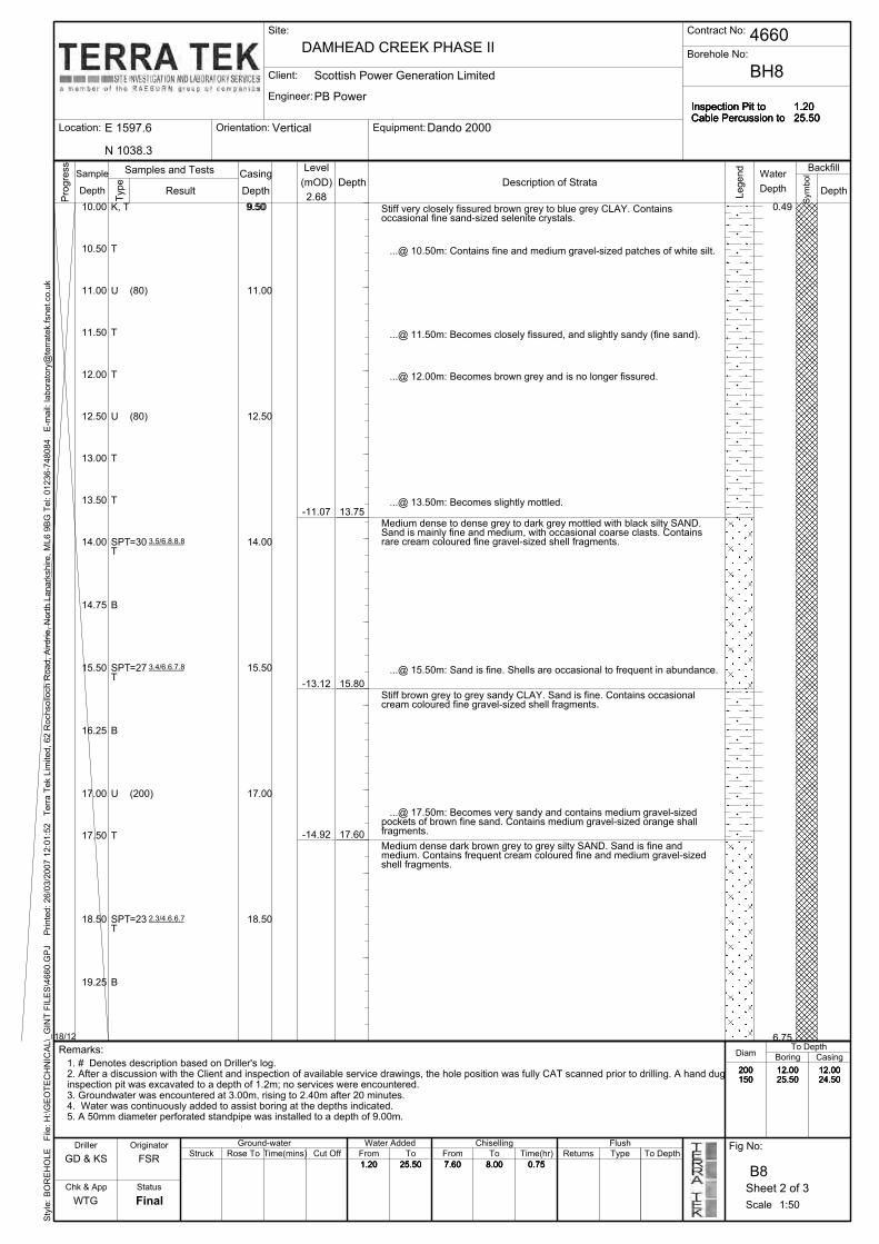
15.50
8.00
1.2025.50
=23
(200)
=27
=30
(80)
(80)
19.25
18.50
17.50
1.20
16.25
200150
14.75
14.00
13.50
13.00
12.50
12.00
11.50
11.00
10.50
10.00
18.50
15.50
Contract No:
17.00
Borehole No:
7.60
Inspection Pit toCable Percussion to
DAMHEAD CREEK PHASE II
1.2025.50
N 1038.3
Dando 2000VerticalOrientation:E 1597.6
Client:
0.75
Location: Equipment:
BH8
7.6025.50
12.0024.50
12.0025.50
Engineer:
-11.07
14.00
12.50
11.00
9.509.50K, T
-13.12
T
6.75
0.49
18/12
17.60
15.80
13.75
-14.92TMedium dense dark brown grey to grey silty SAND. Sand is fine andmedium. Contains frequent cream coloured fine and medium gravel-sizedshell fragments.
...@ 17.50m: Becomes very sandy and contains medium gravel-sizedpockets of brown fine sand. Contains medium gravel-sized orange shallfragments.
Stiff brown grey to grey sandy CLAY. Sand is fine. Contains occasionalcream coloured fine gravel-sized shell fragments.
...@ 15.50m: Sand is fine. Shells are occasional to frequent in abundance.
Medium dense to dense grey to dark grey mottled with black silty SAND.Sand is mainly fine and medium, with occasional coarse clasts. Containsrare cream coloured fine gravel-sized shell fragments.
...@ 13.50m: Becomes slightly mottled.
...@ 12.00m: Becomes brown grey and is no longer fissured.
...@ 11.50m: Becomes closely fissured, and slightly sandy (fine sand).
...@ 10.50m: Contains fine and medium gravel-sized patches of white silt.
Stiff very closely fissured brown grey to blue grey CLAY. Containsoccasional fine sand-sized selenite crystals.
B
17.00
SPT
U
B
TSPT
B
TSPT
T
T
U
T
T
U
T
Flush
CasingDiam
Chk & App
B8
Final
To Depth
FromCut OffTime(mins)
WTG
200150
Site:
Remarks:
Rose To
1.20
Struck
12.0025.50
12.0024.50
1. # Denotes description based on Driller's log.2. After a discussion with the Client and inspection of available service drawings, the hole position was fully CAT scanned prior to drilling. A hand duginspection pit was excavated to a depth of 1.2m; no services were encountered.3. Groundwater was encountered at 3.00m, rising to 2.40m after 20 minutes.4. Water was continuously added to assist boring at the depths indicated.5. A 50mm diameter perforated standpipe was installed to a depth of 9.00m.
FSR25.50
12.0024.50
12.0025.50
200150
1.20 0.758.00
Inspection Pit toCable Percussion to
1.2025.50
Style: BOREHOLE File: H:\GEOTECHNIC
AL\_GIN
T FILES\4660.G
PJ Printed: 26/03/2007 12:01:52 Terra Tek Lim
ited, 62 R
ochsolloch R
oad, Airdrie, North Lanarkshire, ML6 9BG Tel: 01236-748084 E-m
ail: laboratory@
terratek.fsnet.co.uk
GD & KS
DrillerFrom
Fig No:
25.50 7.60
To
Boring
To Time(hr) Returns Type To Depth
Scale
Depth
Level
Progress
Description of StrataSample
Depth
Legend
Result
Samples and Tests Casing
Scottish Power Generation Limited
PB Power
4660
Inspection Pit toCable Percussion to
Symbol
Backfill
Depth
Water(mOD)
Ground-water
Depth
Originator
Status
Water Added
Sheet 2 of 3
1:50
Chiselling
8.00 0.75
Type
2.68Depth
2.3/4.6.6.7
3.4/6.6.7.8
3.5/6.8.8.8
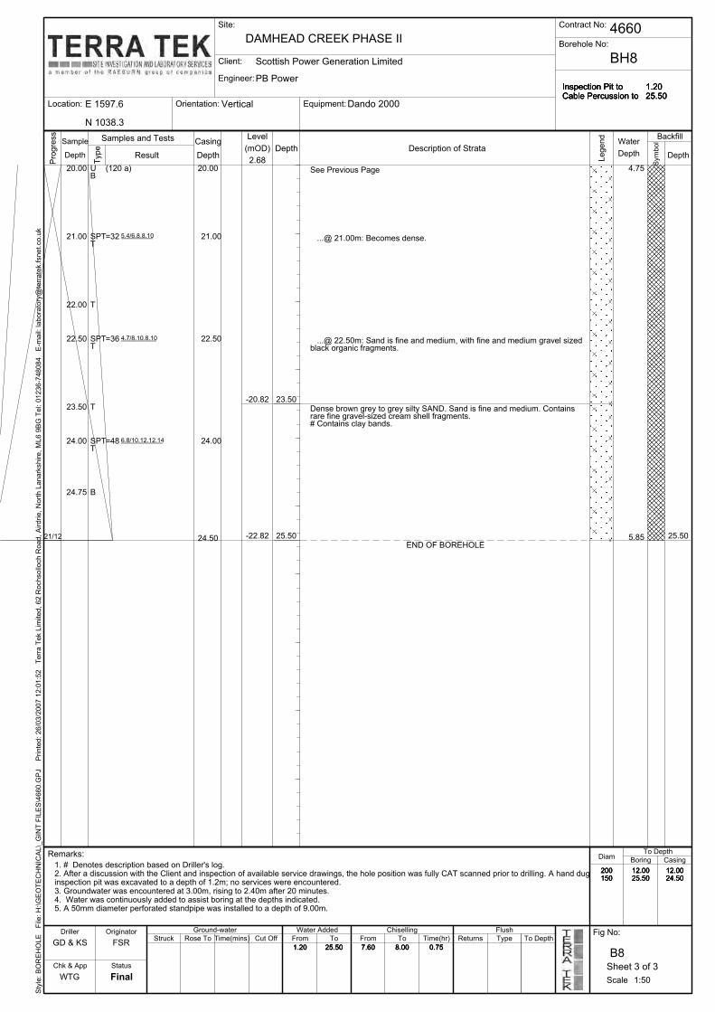
1.2025.50
Inspection Pit toCable Percussion to
7.6025.50
12.0024.50
12.0025.50
200150
1.20 0.75
Inspection Pit toCable Percussion to
7.6025.50
12.0024.50
12.0025.50
200150
1.20 0.758.00
1.2025.50
=48
=36
8.00
Vertical
4660
Scottish Power Generation Limited
Inspection Pit toCable Percussion to
Contract No:Site:
DAMHEAD CREEK PHASE II
1.2025.50
Dando 2000
24.75
Orientation:E 1597.6
Client:
Engineer:
Location:
Borehole No:
Equipment:
BH8
N 1038.3
4.75U
24.50
20.00
-22.82
-20.82
=32
5.85
T
25.5021/12 25.50
23.50Dense brown grey to grey silty SAND. Sand is fine and medium. Containsrare fine gravel-sized cream shell fragments.# Contains clay bands.
PB Power
24.00
23.50
22.50
22.00
21.00
20.00
24.00
22.50
21.00
B
END OF BOREHOLE
SPT
...@ 22.50m: Sand is fine and medium, with fine and medium gravel sizedblack organic fragments.
...@ 21.00m: Becomes dense.
See Previous Page
B
TSPT
T
TSPT
T
(120 a)
12.0024.50
Final
To Depth
FromCut OffTime(mins)Rose ToStruck
Flush
Chk & App
1. # Denotes description based on Driller's log.2. After a discussion with the Client and inspection of available service drawings, the hole position was fully CAT scanned prior to drilling. A hand duginspection pit was excavated to a depth of 1.2m; no services were encountered.3. Groundwater was encountered at 3.00m, rising to 2.40m after 20 minutes.4. Water was continuously added to assist boring at the depths indicated.5. A 50mm diameter perforated standpipe was installed to a depth of 9.00m.
12.0025.50
200150
1.20
Remarks:
Scale
Style: BOREHOLE File: H:\GEOTECHNIC
AL\_GIN
T FILES\4660.G
PJ Printed: 26/03/2007 12:01:52 Terra Tek Lim
ited, 62 R
ochsolloch R
oad, Airdrie, North Lanarkshire, ML6 9BG Tel: 01236-748084 E-m
ail: laboratory@
terratek.fsnet.co.uk
GD & KS
Boring
To DepthTypeReturnsTime(hr)To
B8
To
0.757.6025.50
Fig No:
FSR
WTG
Driller
CasingDiam
From
Casing(mOD) Depth
Progress
Description of StrataSample
Depth
Legend
8.00
Samples and Tests
2.68 Symbol
Depth
Water
Depth
Backfill
Result
Chiselling
1:50
Sheet 3 of 3
Water AddedGround-water
Level
Originator
Depth
Status
Type
6.8/10.12.12.14
4.7/8.10.8.10
5.4/6.8.8.10

T
2.20
2.00
1.60
1.20
0.300.20
T
T
2006
T
B, TJ
Rose To
T
Ground-water
Struck
0.40
Remarks:
2.70
Sheet 1 of 1
29/11
Status
Originator
END OF TRIAL PIT
1:50
DRY 2.7519/11
1.92
2.75
2.45
2.20
0.80
Dark yellow brown very silty SAND. Sand is fine. Contains cobble-sizedpockets of orange brown sand.
Orange brown SAND and GRAVEL. Sand is fine to coarse. Gravel is fine tocoarse of angular to rounded flint.
Stiff orange brown sandy CLAY. Sand is fine to coarse. Contains occasionalcobble-sized pockets of very stiff grey clay.
MADE GROUND: (Brown sandy gravelly CLAY. Sand is fine to coarse.Gravel is fine to coarse, of sub-angular and sub-rounded brick and concrete.Also contains cobbles of brick and concrete, and many grass rootlets).
TOPSOIL: (Grass top over brown sandy slightly gravelly CLAY. Sand is fine.Gravel is fine to coarse, of sub-angular and sub-rounded flint. Containsmany rootlets).3.72
3.32
1.37
1.67
E 1426.3
Client:
Engineer:
Location: Equipment:Type
N 1258.3
1. After a discussion with the Client and inspection of available service drawings, the hole position was fully CAT scanned prior to excavation. No services were encountered.2. No groundwater was encountered.3. Hole was generally stable to 2.50m.4. Upon excavation completion, the trial pit was backfilled with arisings.
Style: TRIALPIT File: H:\GEOTECHNICAL\_GINT FILES\4660.GPJ Printed: 26/03/2007 11:57:05 Terra Tek Limited, 62 Rochsolloch Road, Airdrie, North Lanarkshire, ML6 9BG Tel: 01236-748084 E-m
ail: [email protected]
Scottish Power Generation Limited
PB Power
4660Contract No:Site:
Tracked JCB1 x 2.5
DAMHEAD CREEK PHASE IITrial Pit No:
TP1
Trial Pit to
Dimensions:
2.75
Water
Depth
Backfill
Fig No:
Symbol
WTG
Samples and Tests
Driller
Scale
Chk & App
B9
Final
Cut OffTime(mins)LA
Description of StrataDepth
Progress
DepthDepth
4.12
SampleLevel
(mOD)
Legend
Result

0.20200629/11
2.90
2.30
1.70
1.40
0.50
T
T
T
J, T
THV
0.60
Time(mins)Rose To
(47, 41)
1. After a discussion with the Client and inspection of available service drawings, the hole position was fully CAT scanned prior to excavation. No services were encountered.2. No groundwater was encountered.3. Hole was generally stable.4. Upon excavation completion, the trial pit was backfilled with arisings.
1:50
Sheet 1 of 1
Ground-water
Status
Originator
Remarks:
T
DRY 2.90
2.46
1.86
2.90
2.30
1.70
0.50
29/11
END OF TRIAL PIT
...@ 2.50m: Becomes orange brown with cobble-sized pockets of olivegrey clay.
Stiff dark yellow brown sandy CLAY. Sand is fine to coarse.
Firm dark grey slightly sandy CLAY. Sand is fine to coarse. Containsoccasional fine to medium gravel, of sub-angular and sub-rounded flint.Contains occasional rootlets.
MADE GROUND: (Soft grey pulverised fuel ASH).3.66
1.26
TOPSOIL: (Grass top over brown slightly sandy CLAY. Sand is fine tocoarse. Contains occasional cobble-sized pockets of orange sand.Occasional gravel Is fine to coarse, of sub-angular to sub-rounded flint.Contains many grass rootlets).
E 1438.8
Client:
Engineer:
Location: Equipment:1 x 2.5
N 1163.3
Struck Cut Off
Style: TRIALPIT File: H:\GEOTECHNICAL\_GINT FILES\4660.GPJ Printed: 26/03/2007 11:57:05 Terra Tek Limited, 62 Rochsolloch Road, Airdrie, North Lanarkshire, ML6 9BG Tel: 01236-748084 E-m
ail: [email protected]
Scottish Power Generation Limited
PB Power
4660Contract No:Site:
Tracked JCB
DAMHEAD CREEK PHASE IITrial Pit No:
TP2
Trial Pit to
Dimensions:
2.90
LA
Samples and Tests
Depth
Water
Depth
Backfill
Type
Result
WTG
Driller
Scale
Chk & App
B10
Final
Fig No:
(mOD)Sample
Depth
Progress
Symbol
Depth Description of Strata
4.16 LegendLevel

J, T
2.20
1.301.20
1.00
0.50
HV
HV
Very stiff dark grey brown CLAY.
J, T
END OF TRIAL PIT
B
Sheet 1 of 1
Rose To
(78, 87)
1. After a discussion with the Client and inspection of available service drawings, the hole position was fully CAT scanned prior to excavation. No services were encountered.2. No groundwater was encountered.3. Hole was generally stable.4. Upon excavation completion, the trial pit was backfilled with arisings.
Remarks:
29/11
1:50
2006
Ground-water
Status
Originator
Stiff orange brown sandy CLAY. Sand is fine to coarse.
DRY 2.7029/11
Firm to stiff orange brown sandy CLAY. Sand is fine to coarse. Containsoccasional fine to coarse gravel, of sub-angular to sub-rounded flint.Contains cobble-sized pockets of grey clay.
4.02
2.70
2.10
2.00
1.15
0.25
(44, 50)
...@ 1.00m: Concrete obstruction encountered, so trench was extended.After further excavation, the concrete was removed, measuringapproximately 1m in width and length.
MADE GROUND: (Brown sandy gravelly CLAY. Sand is fine to coarse.Gravel is fine to coarse of sub-angular to sub-rounded concrete and flint).
TOPSOIL: (Grass top over brown slightly sandy CLAY. Sand is fine tocoarse. Contains occasional fine to coarse gravel, of sub-angular andsub-rounded flint. Contains many grass rootlets).
1.57
2.17
2.27
3.12
Struck
E 1436.1
Client:
Engineer:
Location: Equipment:
N 1063.3
Time(mins)
Style: TRIALPIT File: H:\GEOTECHNICAL\_GINT FILES\4660.GPJ Printed: 26/03/2007 11:57:06 Terra Tek Limited, 62 Rochsolloch Road, Airdrie, North Lanarkshire, ML6 9BG Tel: 01236-748084 E-m
ail: [email protected]
Scottish Power Generation Limited
PB Power
4660Contract No:Site:
Tracked JCB1 x 3
DAMHEAD CREEK PHASE IITrial Pit No:
TP3
Trial Pit to
Dimensions:
2.70
SymbolWater
Depth
Backfill
Fig No:
Type
WTG
Samples and Tests
Driller
Scale
Chk & App
B11
Final
Cut OffLA
Progress
SampleDepth
Depth
Level
ResultDescription of Strata
Depth4.27 L
egend
(mOD)

1.20
200629/11
2.80
T
1.80
Originator
0.80
0.30
T
T
T
T
Final
2.40
Remarks:
Cut OffTime(mins)
0.30
Rose ToStruck
1. After a discussion with the Client and inspection of available service drawings, the hole position was fully CAT scanned prior to excavation. No services were encountered.2. No groundwater was encountered.3. Hole was generally stable.4. Upon excavation completion, the trial pit was backfilled with arisings.
1:50
Sheet 1 of 1
Ground-water
Status
2.72
DRY 2.80
T
29/11 0.22 2.80
2.00
1.30
END OF TRIAL PIT
Dark orange brown very sandy GRAVEL. Sand is fine to coarse. Gravel isfine to coarse, of sub-angular to sub-rounded flint.
Dark orange brown SAND. Sand is fine. Contains occasional sub-angularand sub-rounded flint cobbles.
Orange brown very clayey SAND. Sand is fine and medium. Containsoccasional fine and medium gravel, of sub-angular and sub-rounded flint.
1.72
1.02
TOPSOIL: (Grass top over yellow brown sandy CLAY. Sand is fine tocoarse. Contains many grass rootlets).
Tracked JCBE 1548.3
Client:
Engineer:
Location: Equipment:
2.80
B12
Style: TRIALPIT File: H:\GEOTECHNICAL\_GINT FILES\4660.GPJ Printed: 26/03/2007 11:57:06 Terra Tek Limited, 62 Rochsolloch Road, Airdrie, North Lanarkshire, ML6 9BG Tel: 01236-748084 E-m
ail: [email protected]
Scottish Power Generation Limited
PB Power
4660Contract No:Site:
1 x 3
N 1065.8
DAMHEAD CREEK PHASE IITrial Pit No:
TP4
Trial Pit to
Dimensions:
Fig No:
Samples and Tests
Symbol
Depth
Water
Depth
Backfill
Legend
LA
WTG
Driller
Scale
Chk & App
3.02
Description of StrataSample
DepthResult
Level
Progress
Depth
Type (mOD)

-0.04
0.66
1.26
1.96
2.46
Rose To
2.9029/11
Status
Struck
Remarks:
1:50
Ground-waterOriginator
2.90
Sheet 1 of 1
END OF TRIAL PIT
T
T
J, T
T
T ...@ 2.90m: Water puddle in base of pit.
Light brown very clayey SAND. Sand is fine.
...@ 1.80m: Becomes slightly clayey.
Orange brown very clayey SAND. Sand is fine to coarse. Containsoccasional fine to coarse gravel, of sub-angular and sub-rounded flint.
Stiff orange brown sandy gravelly CLAY. Sand is fine to coarse. Gravel isfine to coarse, of sub-angular to rounded flint.
Stiff orange brown sandy CLAY. Sand is fine to coarse.
TOPSOIL: (Grass top over light brown sandy CLAY. Sand is fine to coarse.Contains occasional fine and medium gravel, of sub-angular to sub-roundedflint. Contains many rootlets).
2006
2.20
1.60
0.90
0.40
T
29/11
1.80
2.80
2.40
2.00
1.40
0.70
0.20
Level
Engineer:
Location: Equipment:E 1539.9 Tracked JCBType
2.86
1. After a discussion with the Client and inspection of available service drawings, the hole position was fully CAT scanned prior to excavation. No services were encountered.2. Slow groundwater trickle observed at 1.80m.3. Hole was generally stable to 1.60m, with a slight collapse at the base.4. Upon excavation completion, the trial pit was backfilled with arisings.
DAMHEAD CREEK PHASE IIStyle: TRIALPIT File: H:\GEOTECHNICAL\_GINT FILES\4660.GPJ Printed: 26/03/2007 11:57:07 Terra Tek Limited, 62 Rochsolloch Road, Airdrie, North Lanarkshire, ML6 9BG Tel: 01236-748084 E-m
ail: [email protected]
Scottish Power Generation Limited
PB Power
4660Contract No:Site:
Client:
Depth
Trial Pit No:
TP5
Trial Pit to
Dimensions:
2.90
N 1156.8
1 x 2.5
Driller
(mOD)
Fig No:
LA
Depth
Backfill
Scale
Chk & App
B13
Final
Cut OffTime(mins)
WTG
Progress
Description of StrataSample
Depth
Water
Legend
Result
Samples and Tests
Symbol
Depth

T
1.00
0.50
0.20
TB
TT
Remarks:
T
1.80
T
T
J
T
1:50
0.50
Ground-water
Status
Originator
1.20
1.50
20066/12
2.802.70
2.202.10
...@ 2.45m: Becoming very gravelly.
END OF TRIAL PIT
3.23
DRY 2.80
1.53
1.03
2.80
2.70
2.20
1.20
29/11
Firm to stiff dark orange to brown sandy gravelly CLAY. Sand is mediumand coarse. Gravel is fine to coarse, of angular to rounded flint.
...@ 2.10m: Gravel becomes fine to coarse.
...@ 1.80m: Becoming very sandy.
...@ 1.50m: Becoming brown mottled with orange brown.
Stiff brown sandy CLAY. Sand is fine to coarse. Contains occasional fineand medium gravel, of sub-angular and sub-rounded flint. Containsoccasional fine rootlets.
Orange brown very clayey SAND. Sand is fine to coarse. Containsgravel-sized pockets of light grey silt. Contains occasional rootlets.
TOPSOIL: (Grass top and brambles over orange brown mottled with greysandy CLAY. Sand is fine to coarse. Contains rootlets throughout).
2.53
Light brown clayey SAND. Sand is fine and medium.0.93
Level
Engineer:
Location: Equipment:E 1629.4 Tracked JCB
Sheet 1 of 1
Type
1. After a discussion with the Client and inspection of available service drawings, the hole position was fully CAT scanned prior to excavation. No services were encountered.2. No groundwater was encountered.3. Hole was generally stable.4. Upon excavation completion, the trial pit was backfilled with arisings.
(mOD)
DAMHEAD CREEK PHASE IIStyle: TRIALPIT File: H:\GEOTECHNICAL\_GINT FILES\4660.GPJ Printed: 26/03/2007 11:57:07 Terra Tek Limited, 62 Rochsolloch Road, Airdrie, North Lanarkshire, ML6 9BG Tel: 01236-748084 E-m
ail: [email protected]
Scottish Power Generation Limited
PB Power
4660Contract No:Site:
Client:
3.73
Trial Pit No:
TP6
Trial Pit to
Dimensions:
2.80
N 1070.3
1 x 3
B14
Fig No:
LA
WTG
Driller
Backfill
Chk & App
Depth
Final
Cut OffTime(mins)Rose ToStruck
Scale
Legend
DepthDepth
SampleDescription of Strata
Progress
Result
Samples and Tests
Symbol
Depth
Water

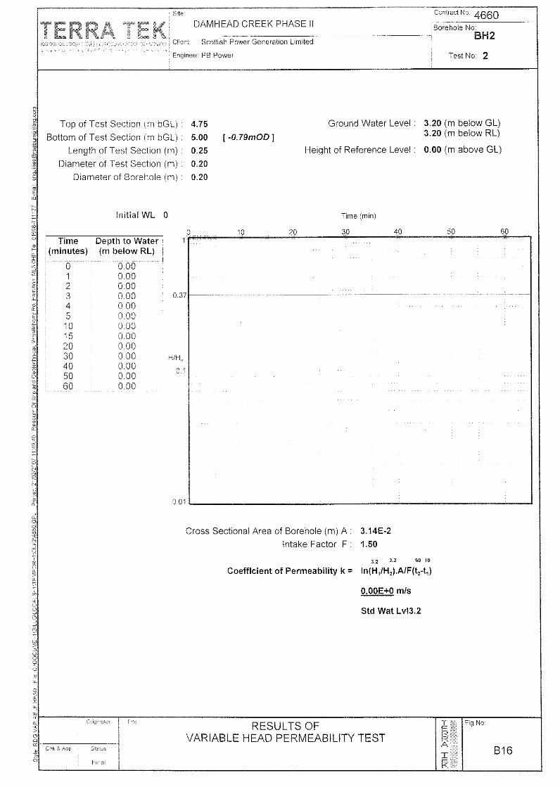


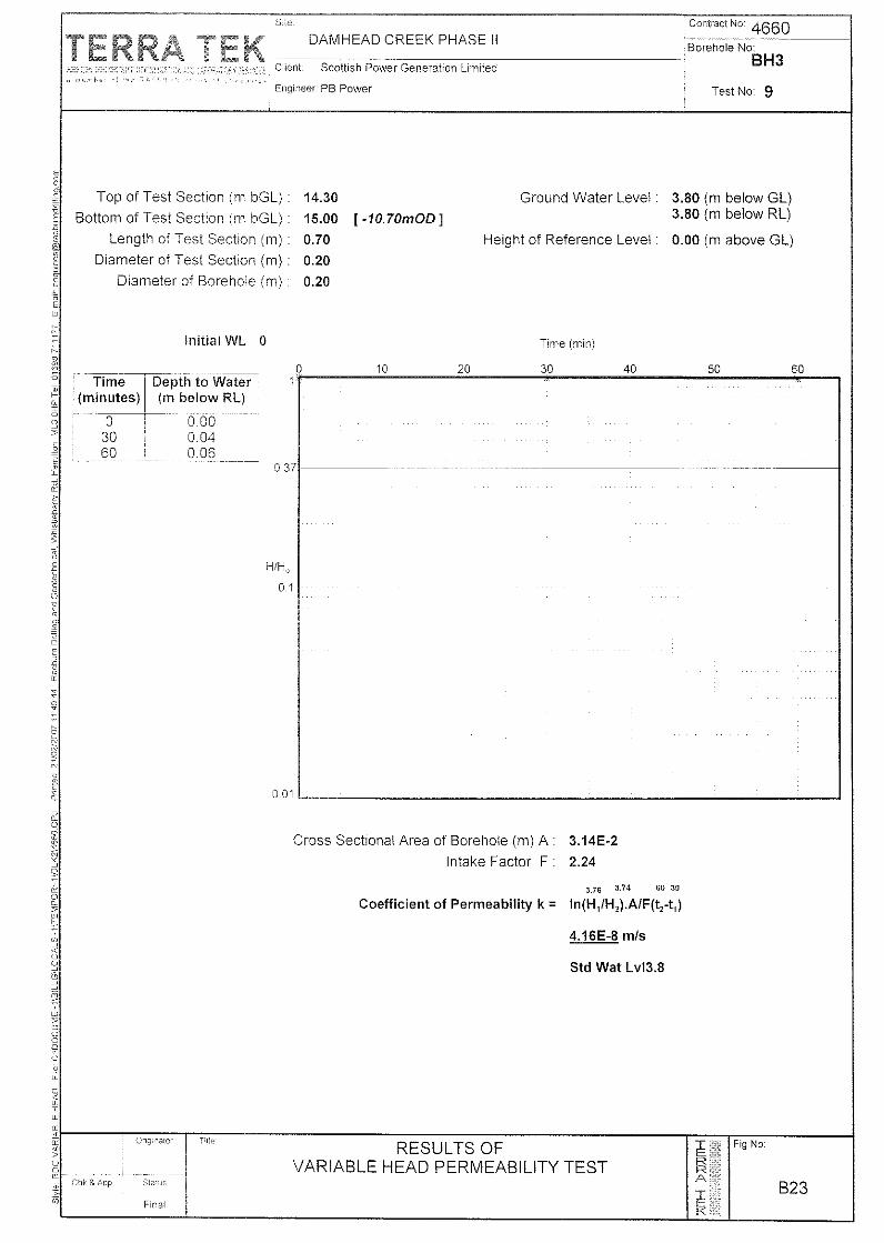


>>
24
20
Status
Originator Title:
Client:
Engineer:
BH8
BH7
BH6
BH5
Fig No:
Style: RDG SPT V DEPTH File: H:\GEOTECHNICAL\_GINT FILES\4660.GPJ Printed: 26/03/2007 12:05:26 Raeburn Drilling and Geotechnical, Whistleberry Rd, Hamilton ML3 0HP Tel: 01698-711177 E-mail: [email protected]
B41WTG Final
FSR
Scottish Power Generation Limited
Style: RDG SPT V DEPTH File: H:\GEOTECHNICAL\_GINT FILES\4660.GPJ Printed: 26/03/2007 12:05:26 Raeburn Drilling and Geotechnical, Whistleberry Rd, Hamilton ML3 0HP Tel: 01698-711177 E-mail: [email protected]
BH2
Chk & App
Contract No: 4660Site:
DAMHEAD CREEK PHASE II
PB Power
16
30
28
26
22
BH4
18
5
14
12
10
8
6
4
2
450
BH1
Key:
N VALUE v DEPTH
Note:
> indicates N Value >50>
N Value500 40353025201510
BH3
Depth (m)
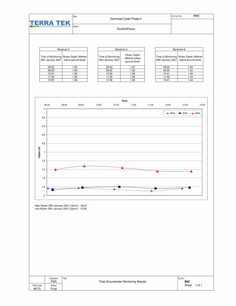
Site: Contract No:
Client:
High Water 29th January 2007 (Upnor) - 09:01
Low Water 29th January 2007 (Upnor) - 15:26
Title: Fig No:
B42
Sheet 1 of 1
Borehole 2 Borehole 6 Borehole 8
1.90
Time of Monitoring
29th January 2007
Water Depth (Metres
below ground level)
08:32 1.84
09:32
10:36
12:25 1.84
09:25 1.83
10:27 1.86
11:32
1.44
11:39
12:38
1.84
1.82
11:42 1.44
12:41
1.82
1.80
Time of Monitoring
29th January 2007
Water Depth
(Metres below
ground level)
08:40 1.87
09:35 1.32
10:41 1.36
Time of Monitoring
29th January 2007
Water Depth (Metres
below ground level)
08:45 1.40
4660
ScottishPower
Damhead Creek Phase II
WTG
Chk & App
Originator
FSR
Status
Tidal Groundwater Monitoring Results
Final
0
0.2
0.4
0.6
0.8
1
1.2
1.4
1.6
1.8
2
0 30 60 90 120 150 180 210 240 270
Time
Dep
th (
m)
BH2 BH6 BH8
09:0008:30 09:30 10:00 10:30 11:00 11:30 12:00 12:30 13:00


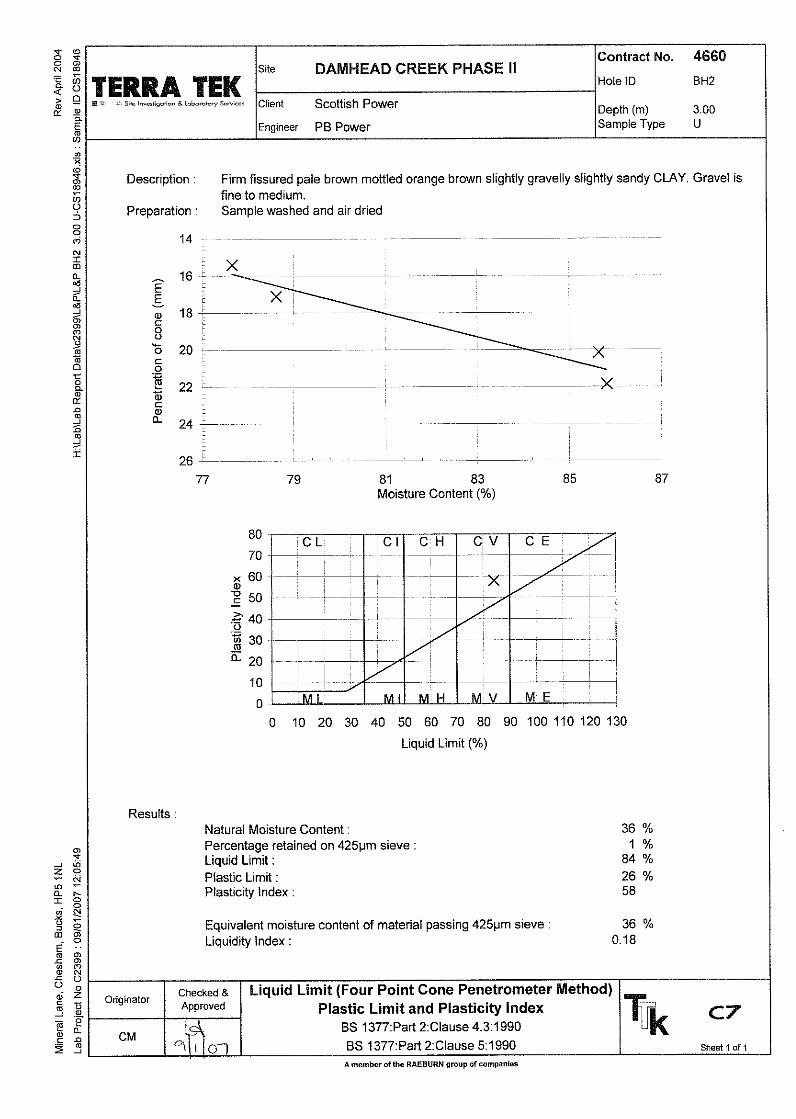


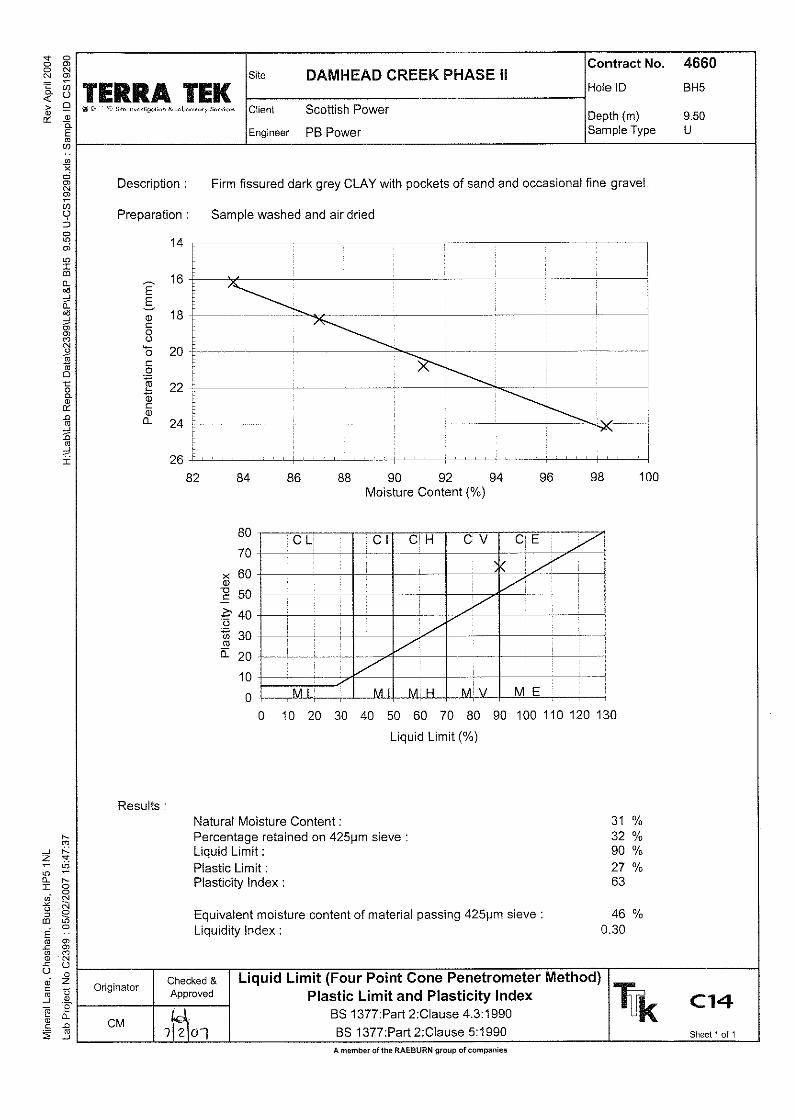


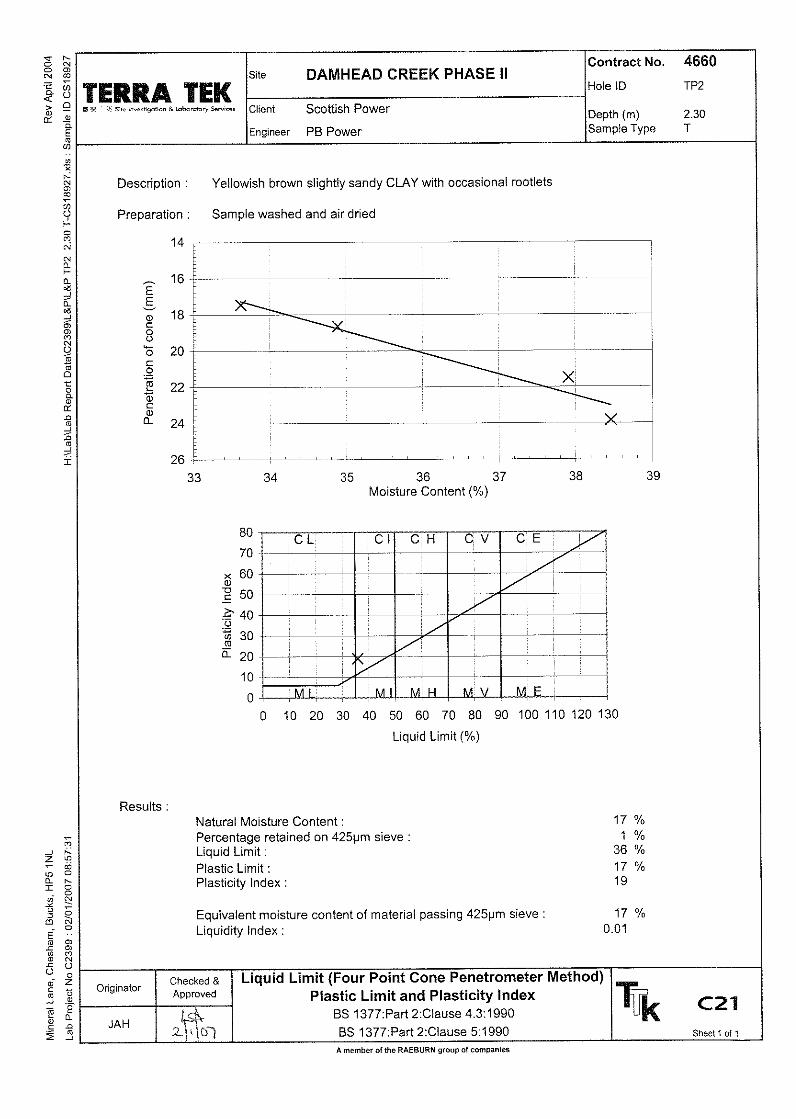


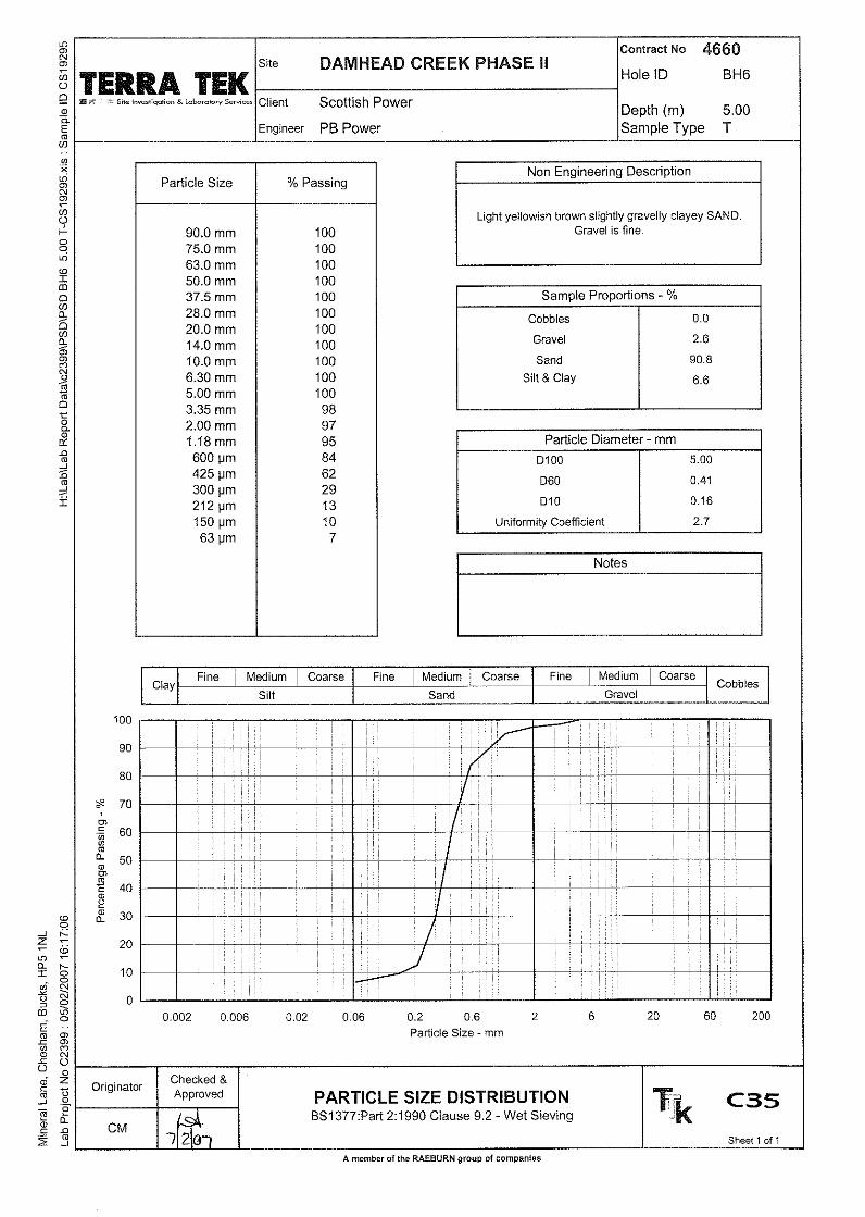


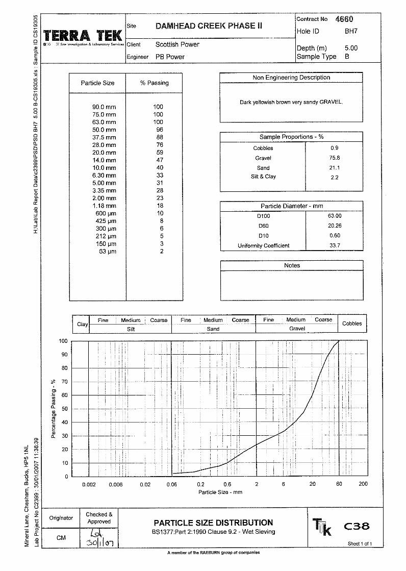


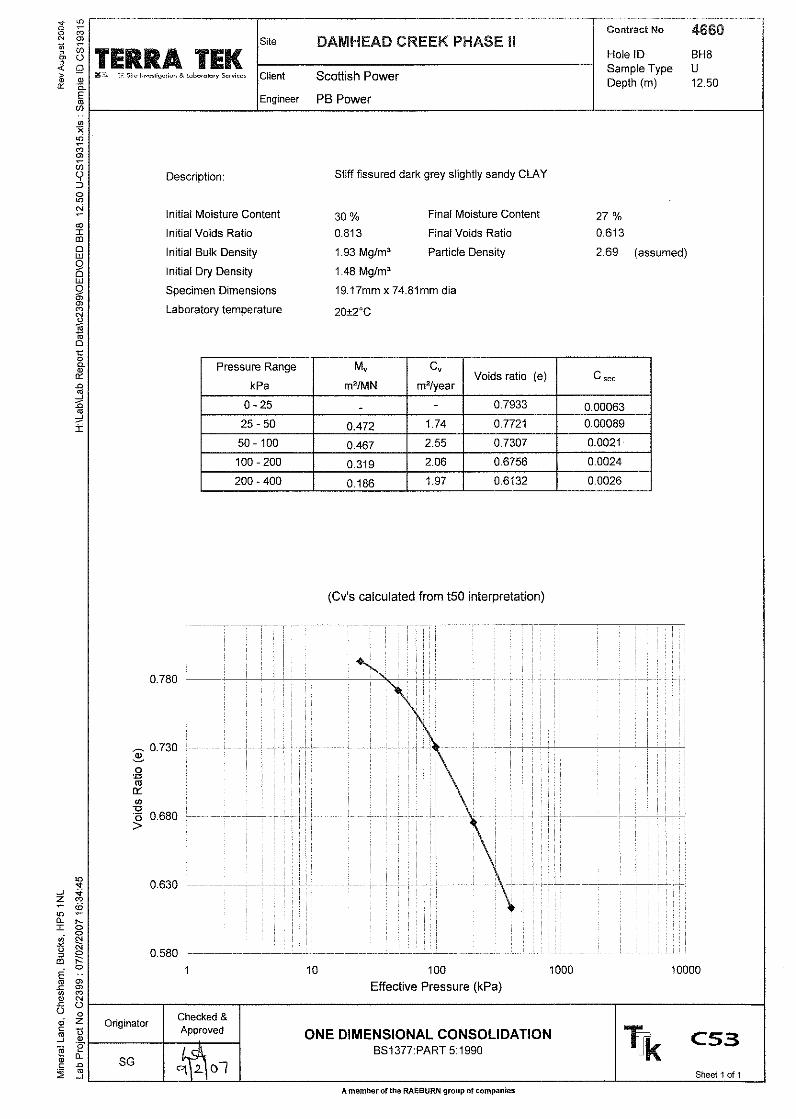

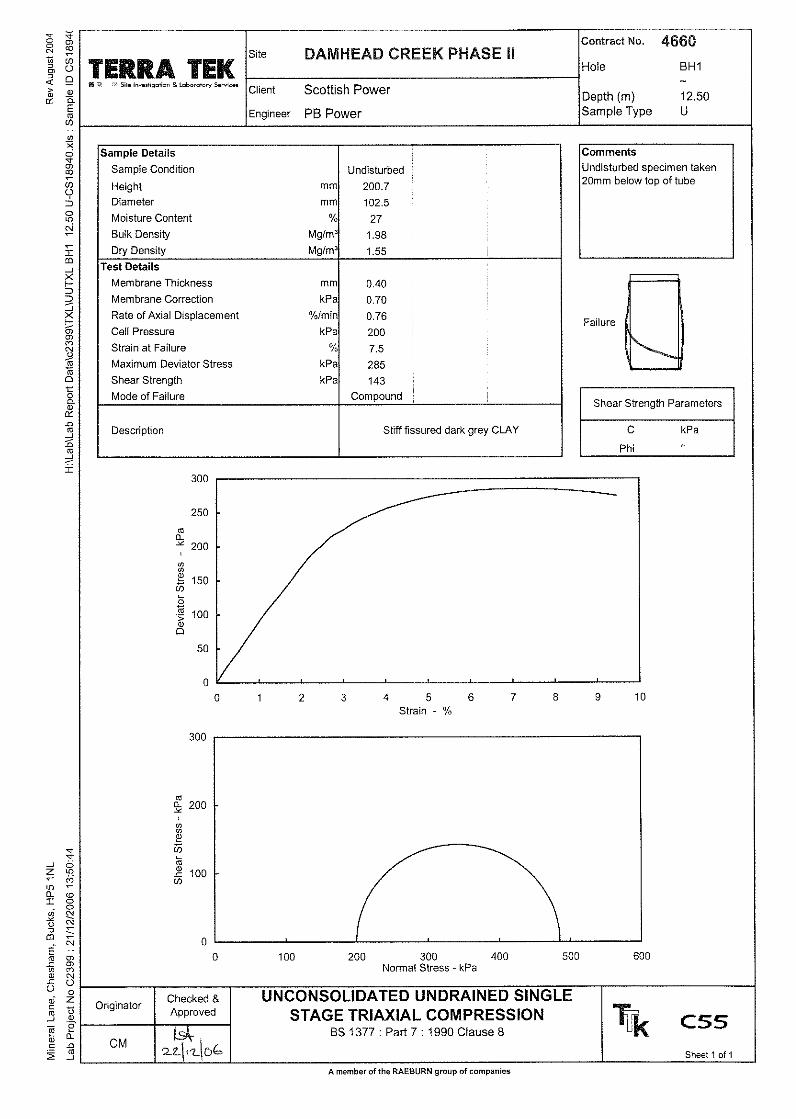


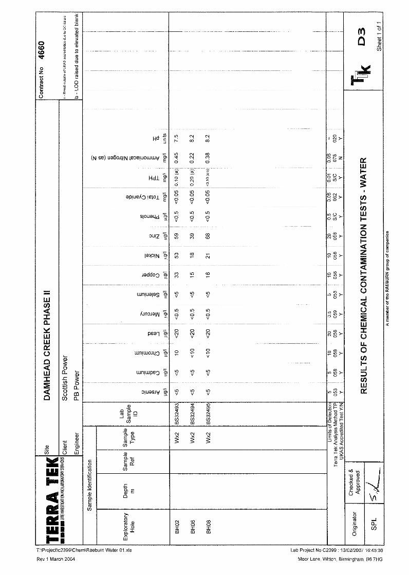


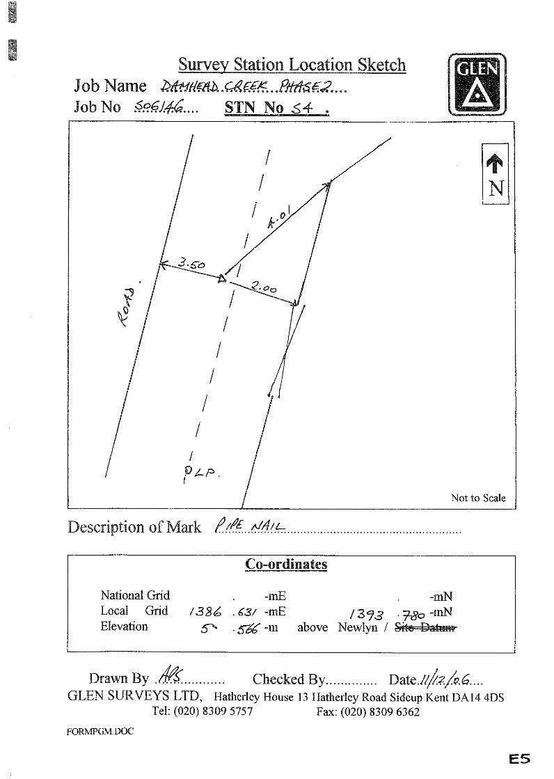


Web Site: www.glensurveys.co.ukE-mail: [email protected]
SIDCUP, KENT DA14 4DS.HATHERLEY HOUSE, 13 HATHERLEY ROAD,
Tel: (020) 8309 5757Fax: (020) 8309 6362
Station National Grid Local Grid
Eastings Northings Eastings Northings Level Remarks
S1 581218.782 172785.501 1489.811 1108.204 3.810 Base StationS2 581539.281 172707.371 1803.441 1005.963 6.058S3 581089.837 172892.994 1369.408 1225.178 5.180S4 581094.205 173062.417 1386.631 1393.780 5.566
Fence Corner Co-Ordinates on NATIONAL GRID
1 581109.034 172958.9292 581132.009 172959.8103 581429.071 172706.0194 581129.916 172685.5605 581129.471 172695.1446 581083.983 172691.9607 581073.341 172901.746
NOTES
1) Survey station description are included in the survey report.
2) The local grid is a plane grid, and is based on the grid for Damhead Creek Phase 1,using a best fit with common detail, as there were no survey stations still existingfrom the previous survey to allow a better fit.
3) The level check with the sea-wall differed by 0.27m, but other checks agreed with theprevious Damhead Creek Phase 1 survey levels. The reason for the difference is unknown.