Embed Size (px)
Citation preview
Appendix H
Energy Efficiency Study
AECOM 3292 Production Way, Floor 4 604 444 6400 tel Burnaby, BC, Canada V5A 4R4 604 294 8597 fax www.aecom.com
Memorandum
Conveyance For LGSWWTP Project Energy Study_2017-04-10.Docx
To Joan Liu, Metro Vancouver Page 1
CC
Subject Conveyance for the NSWWTP – Project Energy Study
From
Susan Spruston, AECOM Brent Start, AECOM
Date April 12, 2017 Project Number 60513172
1. Executive Summary
AECOM has conducted a Project Energy Study for the Bridge Road Pump Station, which is to be constructed as part of the Conveyance for the NSWWTP project. The purpose of the study is to identify major electrical loads, potential power savings and energy conservation measures (ECMs). The study recommendations will be considered when specifying equipment requirements and developing operational strategies to minimize energy consumption. The energy study follows the Vancouver Fraser Port Authority Project Environmental Review (PER) Guidelines.
Energy savings for the pump station will be implemented through the following ECMs incorporated into the design, construction and operation of the new pump station:
• ECM 1.2 Program the control system to operate the pumps in variable speed mode so thepumps operate closer to the best efficiency point (BEP)
• ECM 1.3 Utilize high efficiency motors
• ECM 2.1 Design HVAC for variable air recirculation rates (recirculate 75% when unoccupied)
• ECM 3.1 Provide LED lighting
A description of the system and the proposed ECMs is contained within.

Page 2 NSWWTP Pump Station – Project Energy Study
Conveyance For LGSWWTP Project Energy Study_2017-04-10.Docx
2. Background Information
The Greater Vancouver Sewage and Drainage District is currently undertaking a project to design and construct a new wastewater treatment facility, the North Shore Wastewater Treatment Plant (NSWWTP), which will replace the existing Lions Gate Wastewater Treatment Plant. To convey wastewater to the new NSWWTP and from the NSWWTP to the existing outfall a Conveyance for the NSWWTP project is being completed.
The Conveyance for the NSWWTP project includes the Bridge Road Pump Station. The Bridge Road Pump Station is located on the north shore of the Vancouver Fraser Port Authority’s harbour beneath the Lions Gate Bridge within a RPW established for the Ministry of Transportation and Highways. The proposed pump station will be owned and operated by the Greater Vancouver Sewage and Drainage District (Metro Vancouver).
The pump station is designed to be an unmanned station with intermittent attendance from operations staff for inspections and maintenance. For the purpose of estimating energy consumption it is assumed the building will be occupied 10% of the time, an average 2.4 hrs/day, and unoccupied 90% of the time, 21.6hrs/day.
Page 3 NSWWTP Pump Station – Project Energy Study
Conveyance For LGSWWTP Project Energy Study_2017-04-10.Docx
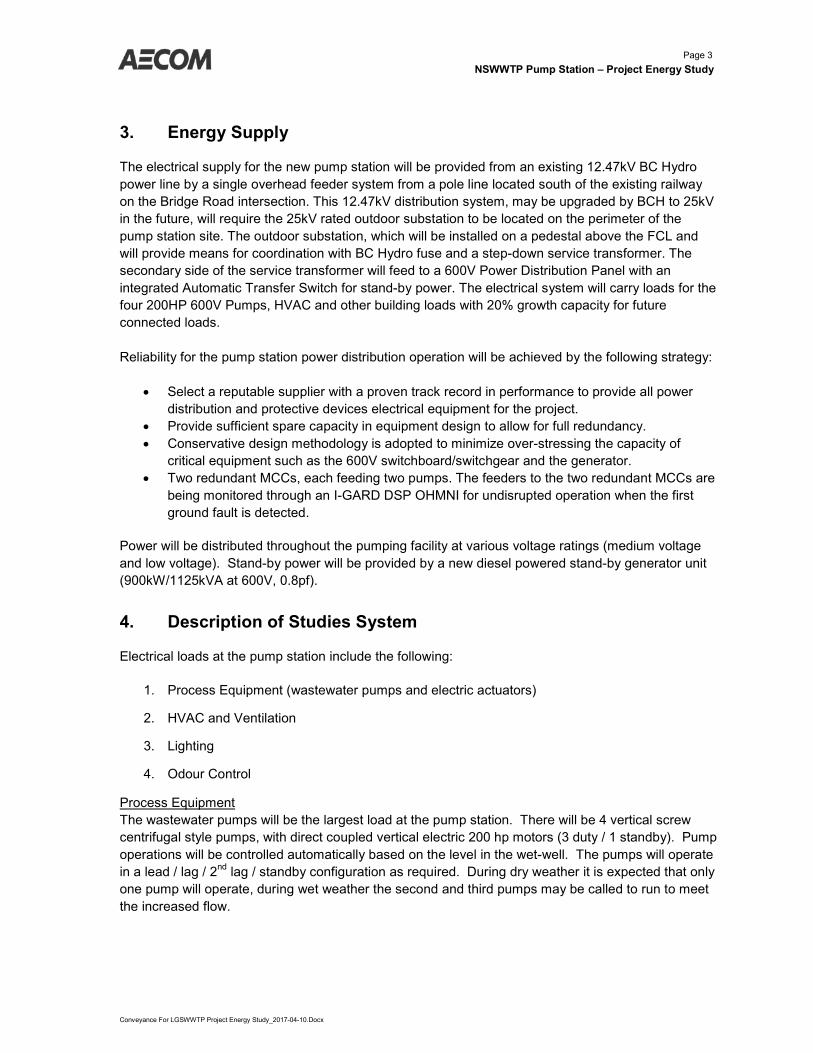
3. Energy Supply
The electrical supply for the new pump station will be provided from an existing 12.47kV BC Hydro power line by a single overhead feeder system from a pole line located south of the existing railway on the Bridge Road intersection. This 12.47kV distribution system, may be upgraded by BCH to 25kV in the future, will require the 25kV rated outdoor substation to be located on the perimeter of the pump station site. The outdoor substation, which will be installed on a pedestal above the FCL and will provide means for coordination with BC Hydro fuse and a step-down service transformer. The secondary side of the service transformer will feed to a 600V Power Distribution Panel with an integrated Automatic Transfer Switch for stand-by power. The electrical system will carry loads for the four 200HP 600V Pumps, HVAC and other building loads with 20% growth capacity for future connected loads.
Reliability for the pump station power distribution operation will be achieved by the following strategy:
• Select a reputable supplier with a proven track record in performance to provide all powerdistribution and protective devices electrical equipment for the project.
• Provide sufficient spare capacity in equipment design to allow for full redundancy.• Conservative design methodology is adopted to minimize over-stressing the capacity of
critical equipment such as the 600V switchboard/switchgear and the generator.• Two redundant MCCs, each feeding two pumps. The feeders to the two redundant MCCs are
being monitored through an I-GARD DSP OHMNI for undisrupted operation when the firstground fault is detected.
Power will be distributed throughout the pumping facility at various voltage ratings (medium voltage and low voltage). Stand-by power will be provided by a new diesel powered stand-by generator unit (900kW/1125kVA at 600V, 0.8pf).
4. Description of Studies System
Electrical loads at the pump station include the following:
1. Process Equipment (wastewater pumps and electric actuators)
2. HVAC and Ventilation
3. Lighting
4. Odour Control
Process Equipment The wastewater pumps will be the largest load at the pump station. There will be 4 vertical screw centrifugal style pumps, with direct coupled vertical electric 200 hp motors (3 duty / 1 standby). Pump operations will be controlled automatically based on the level in the wet-well. The pumps will operate in a lead / lag / 2nd lag / standby configuration as required. During dry weather it is expected that only one pump will operate, during wet weather the second and third pumps may be called to run to meet the increased flow.

Page 4 NSWWTP Pump Station – Project Energy Study
Conveyance For LGSWWTP Project Energy Study_2017-04-10.Docx
In addition to the wastewater pumps each wet well will be equipped with an electrically actuated valve. The load from these valve is negligible compared to the pump load and will only be required for isolation of the wet wells during maintenance.
For long term energy management, the pumps will be equipped with amperage meters and discharge pressure measurement. This data will be monitored and recorded in Metro Vancouver’s CDAC system. Significant changes in amperage draw or discharge pressure can be indicative of an issue such as impeller damage or a blockage in the forcemain which could reduce energy efficiency. On-line data will allow the operators to monitor the pump station performance.
HVAC and Ventilation Forced air ventilation will be provided for all indoor areas of the pump station including the wet wells, dry well, lockers/washroom, electrical room, odour control room, stairwell, generator room and office. Variable ventilation rates will be used to reduce energy consumption, when the spaces are unoccupied and when outdoor air temperatures are below 10○C.
Design indoor temperatures have been set to reduce heating loads. With the exception of the office, lockers/washroom and electrical room; all other spaces have a minimum design temperature of 10○C in the winter. No cooling will be provided with the exception of the electrical room which will have a design maximum summer air temperature of 28○C.
Lighting The lighting system will be designed to maximize the energy efficiency. The design will be in accordance with MV Design standards for utilities and latest edition of the Illuminating Engineering Society of North America Lighting Handbook recommendations. In designing the lighting system, the following selection criteria will be used and Metro Vancouver design standards for linear facilities, with considerations to:
• Use more efficient light sources and luminaire technologies such as LEDs.• Switch off lighting when an area is not occupied, and integrate a security switch and PLC
control to switch off the lighting system when the building is vacant.
Odour Control The odour control system will withdraw air from the pump station wet-wells, treat it in a carbon scrubber, and discharge the treated air above the building roof line through a stack. The system will consist of one variable speed supply air fan to each wet well and one carbon scrubber with one variable speed foul air exhaust fan serving both wet wells.
Page 5 NSWWTP Pump Station – Project Energy Study
Conveyance For LGSWWTP Project Energy Study_2017-04-10.Docx
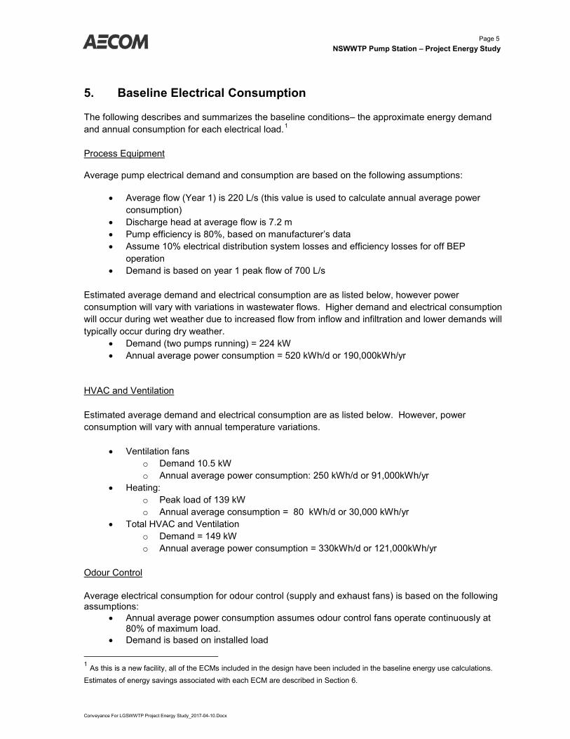
5. Baseline Electrical Consumption
The following describes and summarizes the baseline conditions– the approximate energy demand and annual consumption for each electrical load.1
Process Equipment
Average pump electrical demand and consumption are based on the following assumptions:
• Average flow (Year 1) is 220 L/s (this value is used to calculate annual average powerconsumption)
• Discharge head at average flow is 7.2 m• Pump efficiency is 80%, based on manufacturer’s data• Assume 10% electrical distribution system losses and efficiency losses for off BEP
operation• Demand is based on year 1 peak flow of 700 L/s
Estimated average demand and electrical consumption are as listed below, however power consumption will vary with variations in wastewater flows. Higher demand and electrical consumption will occur during wet weather due to increased flow from inflow and infiltration and lower demands will typically occur during dry weather.
• Demand (two pumps running) = 224 kW• Annual average power consumption = 520 kWh/d or 190,000kWh/yr
HVAC and Ventilation
Estimated average demand and electrical consumption are as listed below. However, power consumption will vary with annual temperature variations.
• Ventilation fanso Demand 10.5 kWo Annual average power consumption: 250 kWh/d or 91,000kWh/yr
• Heating:o Peak load of 139 kWo Annual average consumption = 80 kWh/d or 30,000 kWh/yr
• Total HVAC and Ventilationo Demand = 149 kWo Annual average power consumption = 330kWh/d or 121,000kWh/yr
Odour Control
Average electrical consumption for odour control (supply and exhaust fans) is based on the following assumptions:
• Annual average power consumption assumes odour control fans operate continuously at80% of maximum load.
• Demand is based on installed load
1 As this is a new facility, all of the ECMs included in the design have been included in the baseline energy use calculations. Estimates of energy savings associated with each ECM are described in Section 6.
Page 6 NSWWTP Pump Station – Project Energy Study
Conveyance For LGSWWTP Project Energy Study_2017-04-10.Docx
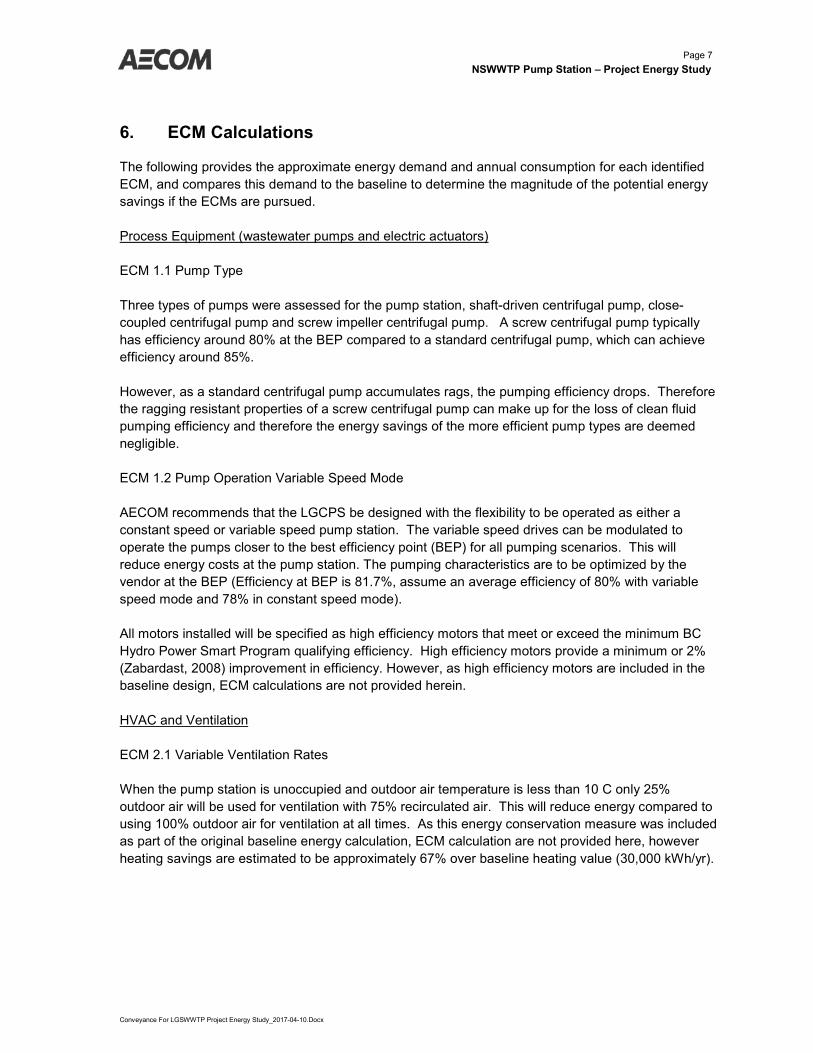
Estimated average demand and electrical consumption are as listed below. • Demand: 11 kW• Annual average power consumption: 211 kWh/d or 77,00kWh/yr
Lighting
Average electrical consumption for lighting is based on the following assumptions: • LED lighting 18 W/Sq.m• Total pump station area 680 m• Demand is based on 90% of installed load.• Annual average consumption based on 10% occupancy (2.4 hrs/day operation)
Lighting energy estimates are: • Demand 15 kW• Annual average consumption 36 kWh/d or 13,000kWh/yr
Summary
Energy usage for the entire pump station can be estimated from the sum of the following Process + HVAC and Ventilation + Odour Control + Lighting.
• Demand = 399 kW• Annual average consumption = 401,000 kWh/yr
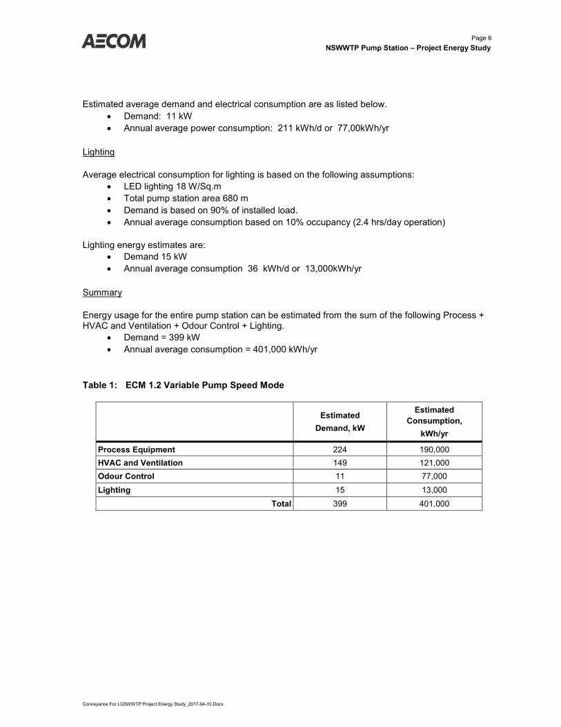
Table 1: ECM 1.2 Variable Pump Speed Mode
Estimated Demand, kW
Estimated Consumption,
kWh/yr
Process Equipment 224 190,000 HVAC and Ventilation 149 121,000 Odour Control 11 77,000
Lighting 15 13,000
Total 399 401,000
Page 7 NSWWTP Pump Station – Project Energy Study
Conveyance For LGSWWTP Project Energy Study_2017-04-10.Docx
6. ECM Calculations
The following provides the approximate energy demand and annual consumption for each identified ECM, and compares this demand to the baseline to determine the magnitude of the potential energy savings if the ECMs are pursued.
Process Equipment (wastewater pumps and electric actuators)
ECM 1.1 Pump Type
Three types of pumps were assessed for the pump station, shaft-driven centrifugal pump, close-coupled centrifugal pump and screw impeller centrifugal pump. A screw centrifugal pump typically has efficiency around 80% at the BEP compared to a standard centrifugal pump, which can achieve efficiency around 85%.
However, as a standard centrifugal pump accumulates rags, the pumping efficiency drops. Therefore the ragging resistant properties of a screw centrifugal pump can make up for the loss of clean fluid pumping efficiency and therefore the energy savings of the more efficient pump types are deemed negligible.
ECM 1.2 Pump Operation Variable Speed Mode
AECOM recommends that the LGCPS be designed with the flexibility to be operated as either a constant speed or variable speed pump station. The variable speed drives can be modulated to operate the pumps closer to the best efficiency point (BEP) for all pumping scenarios. This will reduce energy costs at the pump station. The pumping characteristics are to be optimized by the vendor at the BEP (Efficiency at BEP is 81.7%, assume an average efficiency of 80% with variable speed mode and 78% in constant speed mode).
All motors installed will be specified as high efficiency motors that meet or exceed the minimum BC Hydro Power Smart Program qualifying efficiency. High efficiency motors provide a minimum or 2% (Zabardast, 2008) improvement in efficiency. However, as high efficiency motors are included in the baseline design, ECM calculations are not provided herein.
HVAC and Ventilation
ECM 2.1 Variable Ventilation Rates
When the pump station is unoccupied and outdoor air temperature is less than 10 C only 25% outdoor air will be used for ventilation with 75% recirculated air. This will reduce energy compared to using 100% outdoor air for ventilation at all times. As this energy conservation measure was included as part of the original baseline energy calculation, ECM calculation are not provided here, however heating savings are estimated to be approximately 67% over baseline heating value (30,000 kWh/yr).
Page 8 NSWWTP Pump Station – Project Energy Study
Conveyance For LGSWWTP Project Energy Study_2017-04-10.Docx
Lighting
ECM 3.1 LED Lighting
Energy efficient ED lighting will be specified in the Design and Construction specifications. As this lighting is part of the energy baseline, ECM calculations are not provided herein.
7. Implementation
The following ECMs identified within this energy study are all being included in the design and construction requirements for the Lions Gate SWWTP Conveyance Pump Station:
• ECM 1.2 Variable Speed Pump Control
• ECM 1.3 High Efficiency Motors
• ECM 2.1 Variable Ventilation Rates
• ECM 3.1 LED Lighting
The pump station will be completed by a design build contractor that will be obligated to meet these design and construction requirements.

Page 9 NSWWTP Pump Station – Project Energy Study
Conveyance For LGSWWTP Project Energy Study_2017-04-10.Docx
Appendix A - Calculations
LGSWWTP Conveyance Pump Station Project Energy Study Project No. 60513172March 29, 2017
S. Spruston
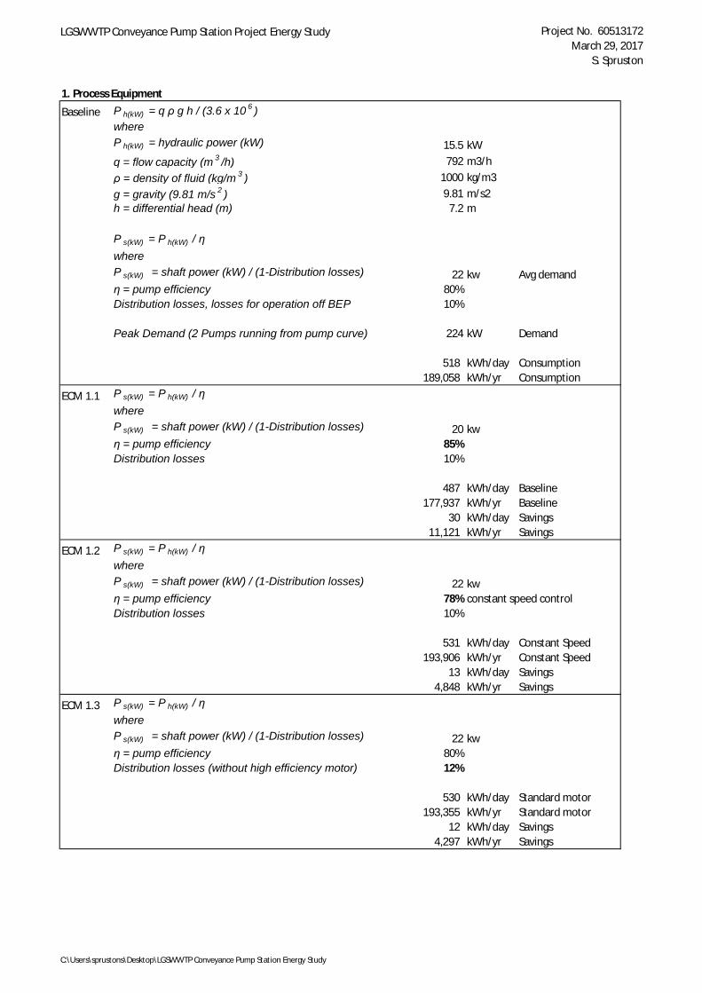
1. Process Equipment
Baseline P h(kW) = q ρ g h / (3.6 x 10 6 )whereP h(kW) = hydraulic power (kW) 15.5 kWq = flow capacity (m 3 /h) 792 m3/hρ = density of fluid (kg/m 3 ) 1000 kg/m3g = gravity (9.81 m/s 2 ) 9.81 m/s2h = differential head (m) 7.2 m
P s(kW) = P h(kW) / ηwhereP s(kW) = shaft power (kW) / (1-Distribution losses) 22 kw Avg demandη = pump efficiency 80%Distribution losses, losses for operation off BEP 10%
Peak Demand (2 Pumps running from pump curve) 224 kW Demand
518 kWh/day Consumption189,058 kWh/yr Consumption
ECM 1.1 P s(kW) = P h(kW) / ηwhereP s(kW) = shaft power (kW) / (1-Distribution losses) 20 kwη = pump efficiency 85%Distribution losses 10%
487 kWh/day Baseline177,937 kWh/yr Baseline
30 kWh/day Savings11,121 kWh/yr Savings
ECM 1.2 P s(kW) = P h(kW) / ηwhereP s(kW) = shaft power (kW) / (1-Distribution losses) 22 kwη = pump efficiency 78% constant speed controlDistribution losses 10%
531 kWh/day Constant Speed193,906 kWh/yr Constant Speed
13 kWh/day Savings4,848 kWh/yr Savings
ECM 1.3 P s(kW) = P h(kW) / ηwhereP s(kW) = shaft power (kW) / (1-Distribution losses) 22 kwη = pump efficiency 80%Distribution losses (without high efficiency motor) 12%
530 kWh/day Standard motor193,355 kWh/yr Standard motor
12 kWh/day Savings4,297 kWh/yr Savings
C:\Users\sprustons\Desktop\LGSWWTP Conveyance Pump Station Energy Study
Appendix A.2 60513172-LGSWWTP Pump Station_Heat Loss Calculation
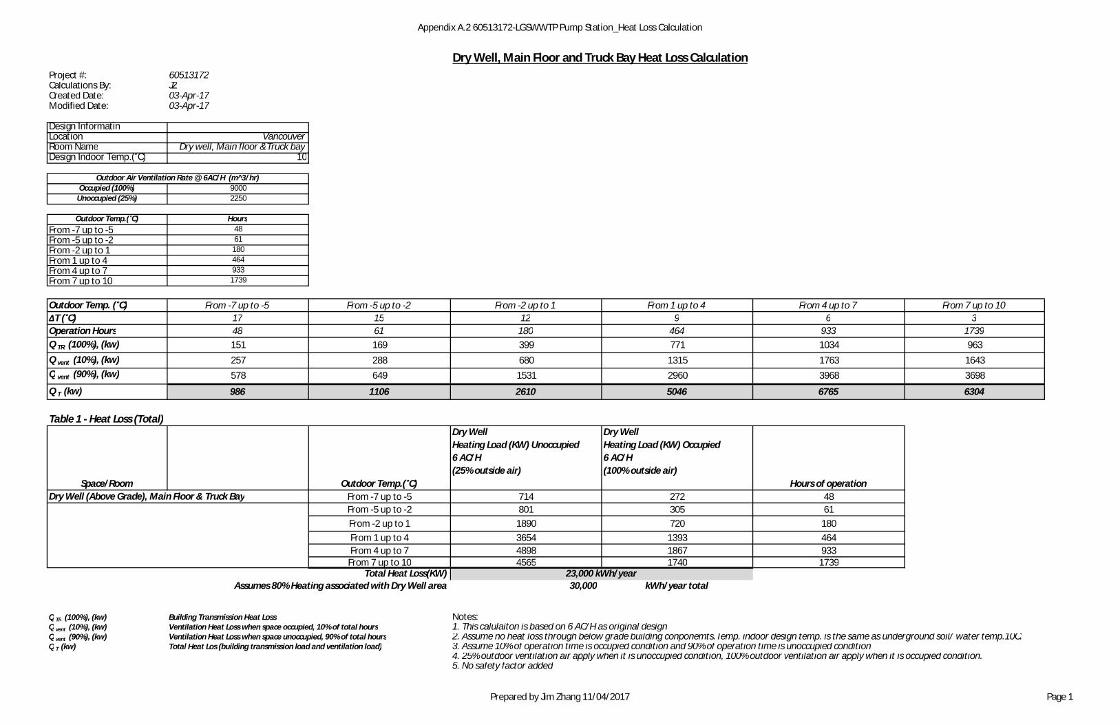
Dry Well, Main Floor and Truck Bay Heat Loss CalculationProject #: 60513172Calculations By: JZCreated Date: 03-Apr-17Modified Date: 03-Apr-17
Design InformatinLocation VancouverRoom Name Dry well, Main floor &Truck bayDesign Indoor Temp.(˚C) 10
Occupied (100%) 9000Unoccupied (25%) 2250
Outdoor Temp.(˚C) HoursFrom -7 up to -5 48From -5 up to -2 61From -2 up to 1 180From 1 up to 4 464From 4 up to 7 933From 7 up to 10 1739
Outdoor Temp. (˚C) From -7 up to -5 From -5 up to -2 From -2 up to 1 From 1 up to 4 From 4 up to 7 From 7 up to 10ΔT (˚C) 17 15 12 9 6 3Operation Hours 48 61 180 464 933 1739Q TR (100%), (kw) 151 169 399 771 1034 963Q vent (10%), (kw) 257 288 680 1315 1763 1643Q vent (90%), (kw) 578 649 1531 2960 3968 3698
Q T (kw) 986 1106 2610 5046 6765 6304
Table 1 - Heat Loss (Total)
Space/Room Outdoor Temp.(˚C)
Dry WellHeating Load (KW) Unoccupied6 AC/H(25% outside air)
Dry WellHeating Load (KW) Occupied6 AC/H(100% outside air)
Hours of operationDry Well (Above Grade), Main Floor & Truck Bay From -7 up to -5 714 272 48
From -5 up to -2 801 305 61From -2 up to 1 1890 720 180From 1 up to 4 3654 1393 464From 4 up to 7 4898 1867 933
From 7 up to 10 4565 1740 1739Total Heat Loss(KW)
Assumes 80% Heating associated with Dry Well area 30,000 kWh/year total
Q TR (100%), (kw) Building Transmission Heat Loss Notes:Q vent (10%), (kw) Ventilation Heat Loss when space occupied, 10% of total hours 1. This calulaiton is based on 6 AC/H as original designQ vent (90%), (kw) Ventilation Heat Loss when space unoccupied, 90% of total hours 2. Assume no heat loss through below grade building conponemts.Temp. indoor design temp. is the same as underground soil/ water temp.10C.Q T (kw) Total Heat Los (building transmission load and ventilation load) 3. Assume 10% of operation time is occupied condition and 90% of operation time is unoccupied condition
4. 25% outdoor ventilation air apply when it is unoccupied condition, 100% outdoor ventilation air apply when it is occupied condition.5. No safety factor added
Outdoor Air Ventilation Rate @ 6AC/H (m^3/hr)
23,000 kWh/year
Prepared by Jim Zhang 11/04/2017 Page 1