Embed Size (px)
Citation preview

APPENDIX G
FINAL ENERCON LAKE KEOWEE WATER LEVEL REDUCTION
STUDY REPORT


Confidential – Business Proprietary
PROJECT REPORT REVISION STATUS SHEET
NO. DUKEONS008-RPT-001
REV. 0
PAGE NO. 2
PROJECT REPORT REVISION STATUS
REVISION DATE DESCRIPTION
0 Initial Issue
PAGE REVISION STATUS
PAGE NO. REVISION PAGE NO. REVISION
All 0
APPENDIX REVISION STATUS
ATTACHMENT NO. PAGE NO. REVISION NO. ATTACHMENT NO. PAGE NO. REVISION NO.
1 All 0 14 All 0
2 All 0 15 All 0
3 All 0 16 All 0
4 All 0 17 All 0
5 All 0 18 All 0
6 All 0 19 All 0
7 All 0 20 All 0
8 All 0 21 All 0
9 All 0 22 All 0
10 All 0 23 All 0
11 All 0 24 All 0
12 All 0 25 All 0
13 All 0

Study Report For Lake Keowee Water Level Reduction ENERCON Report No. DUKEONS008-RPT-001, Rev 0
TABLE OF CONTENTS
3 Confidential – Business Proprietary
1.0 Background and Introduction ......................................................................................16
1.1 Scope ................................................................................................................16
1.2 Background ......................................................................................................16
1.3 Bases for Lake Level Restrictions ...................................................................18
2.0 Study Process Overview ..............................................................................................21
2.1 Study Process for Part 1 – Evaluation of Design Changes for Operation at 787 feet msl ................................................................................24
2.2 Study Process for Part 2 – Evaluation of Design Changes for Operation at 777.1 feet msl ..............................................................................27
3.0 Evaluations ...................................................................................................................28
3.1 Part 1 – Operation at Lake Level of 787 feet msl ............................................28
3.1.1 Activity #1: Verify the Operation of Condenser Circulating Water (CCW) Pumps Provides Adequate Suction Head (Part of Part 1 Options 1a & 1c) .......................................................................29
3.1.2 Activity #2: Size and Location of New Diesel Generators to Power CCW Pumps (Part of Part 1 Option 1a)....................................35
3.1.3 Activity #3: Diesel Generator Support Systems and Equipment Required (Part of Part 1 Option 1a) .....................................................50
3.1.4 Activity #4: Upgrade CCW Pumps and Motors to QA1 (Part of Part 1 Options 1a & 1c) .......................................................................53
3.1.5 Activity #5: Upgrade of CCW Pump Discharge Valves to QA1 (Part of Part 1 Options 1a & 1c) ..........................................................56
3.1.6 Activity #6: Determine if Upgrades are Needed to Existing Cables or Cable Routes (Part of Part 1 Options 1a & 1c) ....................60
3.1.7 Activity #7: Evaluate Modifications to Limit Flow to LPSW Loads (Part 1, Option 1b) ....................................................................61
3.1.8 Activity #8: Evaluate Modifications to Limit Flow to HPSW Loads (Part 1, Option 1b) ....................................................................75
3.1.9 Activity #9: Modifications to Chiller Condenser Service Water Pump Supply Line (Part 1, Option 1b) ................................................77
3.1.10 Activity #10: Upgrade to the Keowee Hydro Power Path to Power CCW Pumps (Part of Part 1 Option 1c)....................................80
3.1.11 Activity #11: Provide Detailed Evaluation of Feasibility of Alternatives (For Part 1 Options 1a, 1b & 1c) .....................................85
3.2 Part 2 – Operation at Lake of Level 777.1 feet msl .........................................98
3.2.1 Activity #1: Size and Location of New Diesel Generators to Replace Keowee Hydro .......................................................................98

Study Report For Lake Keowee Water Level Reduction ENERCON Report No. DUKEONS008-RPT-001, Rev 0
TABLE OF CONTENTS
4 Confidential – Business Proprietary
3.2.2 Activity #2: Diesel Generator Support Systems and Equipment Required .............................................................................................125
3.2.3 Activity #3: Provide Detailed Evaluation of Feasibility ....................125
4.0 Impact On Licensing Basis ........................................................................................134
4.1 Consideration of Implementation Under 10 CFR 50.59 Process ...................134
4.1.1 Part 1 Option 1a .................................................................................134 4.1.2 Part 1 Option 1b .................................................................................135 4.1.3 Part 1 Option 1c .................................................................................136 4.1.4 Part 2 Option 1 ...................................................................................137 4.1.5 Part 2 Option 2 ...................................................................................140
4.2 Implementation Phase ....................................................................................142
4.2.1 Part 1 Option 1a .................................................................................142 4.2.2 Part 1 Option 1b .................................................................................143 4.2.3 Part 1 Option 1c .................................................................................143 4.2.4 Part 2 Option 1 ...................................................................................143 4.2.5 Part 2 Option 2 ...................................................................................144
5.0 Plant Impacts ..............................................................................................................144
5.1 Design documentation ...................................................................................144
5.2 Procedural ......................................................................................................145
5.3 Programmatic .................................................................................................145
6.0 Project Schedules .......................................................................................................146
7.0 Economic Estimates and Overall Project Costs .........................................................147
7.1 Initial Capital Costs........................................................................................147
7.1.1 Design ................................................................................................147 7.1.2 Procurement .......................................................................................147 7.1.3 Implementation ..................................................................................148
7.2 Lost Generating Capacity During Implementation Outage ...........................148
7.3 Operations and Maintenance (O&M) Cost ....................................................148
7.3.1 Operational Burden (Cost) .................................................................149 7.3.2 Maintenance Burden (Cost) ...............................................................149
8.0 References ..................................................................................................................154
Attachments ...........................................................................................................................157

Study Report For Lake Keowee Water Level Reduction ENERCON Report No. DUKEONS008-RPT-001, Rev 0
5 Confidential – Business Proprietary
LIST OF TABLES
Table 1-1 SLC 16.9.7 Keowee Lake Level Commitments
Table 3-1A # CCW Pumps Required to Provide Adequate LPSW NPSH Versus Lake Level (emergency discharge flow set @ 0 gpm)
Table 3-1B # CCW Pumps Required to Provide Adequate LPSW NPSH Versus Lake Level (emergency discharge flow set @ 30,000 gpm)
Table 3-2 Electrical Load Capacity for CCW Pump DGs (Part 1 Option 1a)
Table 3-3 Part 1 Option 1a CCW DG Breaker Alignment Matrix
Table 3-4 Electrical Considerations for Potential Diesel Generator Sites Part 1 Option 1a
Table 3-5 LPSW Engineered, Safety Related Component Flow Demands
Table 3-6 Evaluation of Minimum Required Lake Level
Table 3-7 Non-Safety Related Loads In LPSW System
Table 3-8 Calculated Minimum Lake Level by Eliminating/Reducing Non-Safety Related Loads
Table 3-9 Output Variations Between KYPIPE And EPANET
Table 3-10 Proposed Modification Options of LPSW System
Table 3-11 LPSW Modification Options and Corresponding LPSW Flow Reduction
Table 3-12 Combination of Modification Options and Impact to Lake Level Requirements
Table 3-13 Comparison of Flow Reduction Between Summation of Flow Reduction From Each Modification Option and the LPSW Modification Model Output by EPANET
Table 3-14 HPSW Pump NPSH
Table 3-15 CCSW Tie-in to LPSW Essential Header, Effect on Required Lake Level
Table 3-16 Electrical Load Capacity for CCW Pump Keowee Hydro Feeder (Part 1 Option 1c)
Table 3-17 Lake Temperature versus NPSHA
Table 3-18 Electrical Load Requirements
Table 3-19 Bounding Electrical Load Requirements
Table 3-20 CCW Pump & Valve Electrical Load
Table 3-21 Total Electrical Load (LOOP/LOCA Load Plus CCW Pump & Valve Load)
Table 3-22 Electrical Considerations for Potential Diesel Generator Sites, Part 2 Option 1
Table 3-23 Capacity Requirements of Non-Safety DGs
Table 3-24 Electrical Considerations for Potential Diesel Generator Sites, Part 2 Option 2
Table 7-1 Project Cost Estimates
Table 7-2A Part 1 Option 1b Cost Estimates, No Modification to HPSW, No Modification to CCSW Supply Piping
Table 7-2B Part 1 Option 1b Cost Estimates, Modify HPSW (5400 gpm), No Modification to CCSW Supply Piping

Study Report For Lake Keowee Water Level Reduction ENERCON Report No. DUKEONS008-RPT-001, Rev 0
6 Confidential – Business Proprietary
LIST OF FIGURES
Figure 2-1 Study Process Flowchart
Figure 3-1 Part 1 Option 1a CCW DG Configuration
Figure 3-2 Illustration of Unit 1 and Unit 2 component cooler flow modifications
Figure 3-3 Illustration of RCP flow modifications for a typical unit
Figure 3-4 CCW Powered by Keowee Hydro
Figure 3-5 Part 2 Option 1 Safety Related DG Configuration
Figure 3-6 Part 2 Option 2 Non-Safety Related DG Configuration

Study Report For Lake Keowee Water Level Reduction ENERCON Report No. DUKEONS008-RPT-001, Rev 0
ACRONYMS/ABBREVIATIONS/INITIALISMS
7 Confidential – Business Proprietary
approx. approximately
ASME American Society of Mechanical Engineers
ASTs above ground storage tanks
ASW Auxiliary Service Water
BAQ Bureau of Air Quality
BMPs best management practices
BRE bullet resistant enclosure
CCSW Chiller Condenser Service Water
CCSWPs Chiller Condenser Service Water Pumps
CCW Condenser Circulating Water
CFR Code of Federal Regulations
CGD commercial grade dedication
CGI commercial grade item
CMTR Certified Material Test Reports
Corps US Army Corps of Engineers
ctmt containment
DBD Design Basis Documents
DBE Design Basis Earthquake
DG diesel generator
E&S erosion, sedimentation and control
ECCW Emergency Condenser Circulating Water
EFW Emergency Feedwater
EPA Environmental Protection Agency
EPRI Electric Power Research Institute
EQ Environmental Qualification
ES Engineered Safeguards
ESI Engine Systems, Inc.
ESV Essential Siphon Vacuum
EWST elevated water storage tank
ft feet
FERC Federal Energy Regulatory Commission
FME Fairbanks Morse Engine
gpm gallons per minute
HPI High Pressure Injection
HPSW High Pressure Service Water
HVAC Heating, Ventilation, and Air Conditioning
IDS Intrusion Detection System
IEEE Institute of Electrical and Electronics Engineers
IP Inspection Procedure

Study Report For Lake Keowee Water Level Reduction ENERCON Report No. DUKEONS008-RPT-001, Rev 0
ACRONYMS/ABBREVIATIONS/INITIALISMS
8 Confidential – Business Proprietary
ISFSI Independent Spent Fuel Storage Installation
ISI Inservice Inspection
IST Inservice Testing
JD Jurisdictional Determination
KHU Keowee Hydro Unit
kva kilovolt-amperes
kW kilowatt
LCO Limiting Conditions for Operation
LLC current lake level
LLR required lake level
LOCA loss of coolant accident
LOOP loss of offsite power
LPI Low Pressure Injection
LPSW Low Pressure Service Water
max maximum
MDEFW Motor Driven Emergency Feedwater
MDEFWP MDEFW pump
MHE Maximum Hypothetical Earthquake
min minimum
MOV Motor Operated Valve
msl mean sea level
MTOT main turbine oil tank
MVA million volt-amperes
MW megawatt
NCIG Nuclear Construction Issues Group
NOI Notice of Intent
NPDES National Pollutant Discharge Elimination System
NPSH net positive suction head
NPSHA NPSH available
NPSHmargin NPSH margin
NPSHR NPSH required
NRC Nuclear Regulatory Commission
NRC IP NRC Inspection Procedure
O&M Operations and Maintenance
OCA Owner Controlled Area
ONS Oconee Nuclear Station
PA Protected Area
Patm atmospheric pressure
PCN Pre-Construction Notification

Study Report For Lake Keowee Water Level Reduction ENERCON Report No. DUKEONS008-RPT-001, Rev 0
ACRONYMS/ABBREVIATIONS/INITIALISMS
9 Confidential – Business Proprietary
PM Preventive Maintenance
PSD Prevention of Significant Deterioration
psig pound-force per square inch gauge
psid pounds per square inch differential
PSW Protected Service Water
PRA Probabilistic Risk Assessment
QA Quality Assurance
QA1 QA Condition 1
RB Reactor Building
RBCU RB Cooling Units
RCP reactor coolant pump
RCW Recirculated Cooling Water
S&L Sargent and Lundy
SCDHEC South Carolina Department of Health and Environmental Control
SCS Security Computer System
SEPA Southeastern Power Administration
Sec second
SLC Selected Licensee Commitments
SPCC spill prevention controls and countermeasures
SQUG Seismic Qualification Utility Group
SSD Safe Shutdown
SSF Standby Shutdown Facility
SSW Siphon Seal Water
SWPP Stormwater Pollution Prevention Plan
TDEFW Turbine Driven Emergency Feed Water
UFSAR Updated Final Safety Analysis Report
UPS uninterruptable power supply
USACE US Army Corps of Engineers
WC Control Room Ventilation Chilled Water System

Study Report For Lake Keowee Water Level Reduction ENERCON Report No. DUKEONS008-RPT-001, Rev 0
10 Confidential – Business Proprietary
Executive Summary
This study was conducted for the Oconee Nuclear Station (ONS) to determine the feasibility and cost of
design changes necessary to allow station operation at lower Lake Keowee levels than currently restricted to
in order to support relicensing of the Keowee-Toxaway Project by the Federal Energy Regulatory
Commission (FERC).
Five options were considered for the study:
Upgrade the Condenser Circulating Water (CCW) system pumps, discharge valves and their
associated motors and controls to QA1 and power them from safety related diesel generators to
replace the Emergency CCW (ECCW) system (siphon) as the water supply for the Low Pressure
Service Water (LPSW) system, High Pressure Service Water (HPSW) system and Chiller Condenser
Service Water (CCSW) system, in order to allow plant operation at a Lake Keowee level of 787 ft
msl (Part 1 Option 1a)
Reduce flow of the LPSW and HPSW systems (by reducing or eliminating non-essential loads
during loss of offsite power events) in order to reduce these systems’ required net positive suction
head (NPSHR) which would allow plant operation at a Lake Keowee level of 787 ft msl. Initially,
this option considered supplying CCSW pumps from the LPSW essential header rather than the
CCW crossover header. The scope of the study was subsequently revised to consider providing a
booster pump to increase the NPSHA to the CCSW pumps. (Part 1 Option 1b)
Upgrade the CCW pumps, discharge valves and their associated motors and controls to QA1 and
power them from an upgraded safety related power supply from Keowee Hydro to replace the
ECCW system (siphon) as the water supply for the LPSW system, HPSW system and CCSW
system, in order to allow plant operation at a Lake Keowee level of 787 ft msl (Part 1 Option 1c)
Upgrade the CCW pumps, discharge valves and their associated motors and controls to QA1 and
power them and all Oconee safety related electrical loads and PSW loads from safety related diesel
generators to replace the ECCW system (siphon) as the water supply for the LPSW system, HPSW
system and CCSW system, and to eliminate reliance on the Keowee Hydro unit for safety related
power in order to allow plant operation at a Lake Keowee level of 777.1 ft msl (Part 2 Option 1)

Study Report For Lake Keowee Water Level Reduction ENERCON Report No. DUKEONS008-RPT-001, Rev 0
11 Confidential – Business Proprietary
Upgrade the CCW pumps, discharge valves and their associated motors and controls to QA1 and
power them and all Oconee safety related loads, PSW loads, and non-safety related loads from safety
related and non-safety related diesel generators to replace the ECCW system (siphon) as the water
supply for the LPSW system, HPSW system and CCSW system, and to eliminate reliance on the
Keowee Hydro unit for safety related, PSW, and non-safety related power in order to allow plant
operation at a Lake Keowee level of 777.1 ft msl (Part 2 Option 2)
Each of the above options was thoroughly investigated via plant walkdowns, site personnel interviews,
document research, and hydraulic analyses. Based on the investigations, conceptual designs were developed
for each option. Each conceptual design was evaluated for feasibility, plant impact, and licensing basis
impact. Finally, the cost of each option was developed. The cost estimates considered design costs,
procurement costs, implementation costs and annual operations and maintenance (O&M) costs. For the
options considered, a summary of costs is presented in Table 7-1, and detailed in Attachments 23 and 24.
Costs for the possible modifications to LPSW, HPSW and CCSW considered in Part 1 Option 1b are
presented in Tables 7-2A and 7-2B. These modification costs are broken down by cost per foot of Lake
Keowee level reduction.
The study concluded that all of the options considered are feasible and all of the options can meet their stated
target of required Keowee Lake level reduction. Based on preliminary hydraulic analysis, it was determined
that adding CCSW flow to the LPSW system essential header would actually require an increase to
minimum lake level. However, some improvement on lake level can be realized via Option 1b by
implementing LPSW flow reduction option L1 (component cooler isolation modification) and option L5
(analytically accounting for isolation of the non-essential LPSW header) in conjunction with the HPSW flow
reduction modification option. This combination of modifications allows for reduction of the lake level down
to 790 ft. msl, which is the limit currently imposed by SLC 16.9.7.g for operation of the CCSW pumps. The
scope of the study was subsequently expanded to consider providing a booster pump in the supply piping
from the CCW crossover header to the CCSW pumps. Adding this modification will achieve the target lake
level of 787 ft msl. See section 3.1.9 of the report for further discussion of this subject.
The following table summarizes the estimated capital cost and annual O&M costs for each option evaluated
in the study (refer to Section 3.1.7 of the report for a description of each of the flow reduction options for the
LPSW system):
Study Report For Lake Keowee Water Level Reduction ENERCON Report No. DUKEONS008-RPT-001, Rev 0
12 Confidential – Business Proprietary
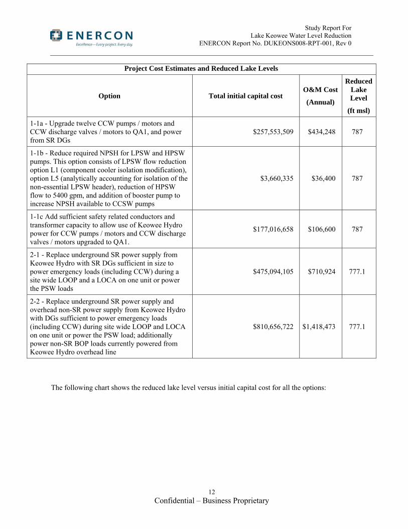
Project Cost Estimates and Reduced Lake Levels
Option Total initial capital cost O&M Cost
(Annual)
Reduced Lake Level
(ft msl)
1-1a - Upgrade twelve CCW pumps / motors and CCW discharge valves / motors to QA1, and power from SR DGs
$257,553,509 $434,248 787
1-1b - Reduce required NPSH for LPSW and HPSW pumps. This option consists of LPSW flow reduction option L1 (component cooler isolation modification), option L5 (analytically accounting for isolation of the non-essential LPSW header), reduction of HPSW flow to 5400 gpm, and addition of booster pump to increase NPSH available to CCSW pumps
$3,660,335 $36,400 787
1-1c Add sufficient safety related conductors and transformer capacity to allow use of Keowee Hydro power for CCW pumps / motors and CCW discharge valves / motors upgraded to QA1.
$177,016,658 $106,600 787
2-1 - Replace underground SR power supply from Keowee Hydro with SR DGs sufficient in size to power emergency loads (including CCW) during a site wide LOOP and a LOCA on one unit or power the PSW loads
$475,094,105 $710,924 777.1
2-2 - Replace underground SR power supply and overhead non-SR power supply from Keowee Hydro with DGs sufficient to power emergency loads (including CCW) during site wide LOOP and LOCA on one unit or power the PSW load; additionally power non-SR BOP loads currently powered from Keowee Hydro overhead line
$810,656,722 $1,418,473 777.1
The following chart shows the reduced lake level versus initial capital cost for all the options:

Study Report For Lake Keowee Water Level Reduction ENERCON Report No. DUKEONS008-RPT-001, Rev 0
13 Confidential – Business Proprietary

Study Report For Lake Keowee Water Level Reduction ENERCON Report No. DUKEONS008-RPT-001, Rev 0
14 Confidential – Business Proprietary
This study does not attempt to make a recommendation; the intent of the study was to provide a
detailed evaluation of the feasibility of performing modifications to reduce required Lake Keowee
levels and to establish cost estimates for each option considered. For Part 1, it can be seen that
Option 1b is the lowest cost option for achieving the Study Part 1 objective of plant operation at Lake
Keowee levels down to 787 ft msl. For Part 2, the two options considered are not equivalent;
therefore, they cannot be compared directly for cost. Part 2 Option 1 only powers safety related and
PSW loads, whereas Part 2 Option 2 powers the non-essential loads in addition to the safety related
and PSW loads currently supplied by Keowee Hydro; therefore, they present different capabilities.
Limitations and Issues beyond the Scope of the Study:
Industry accepted estimating techniques were utilized for all of the options considered for this study.
However, there are risks which cannot be fully explored in a feasibility/conceptual design study such
as this one. For example, for Part 1 Option 1c, Upgrade to the Keowee Hydro Power Path to Power
CCW Pumps, the capital costs associated with this option was estimated to be approximately $177M.
An existing project at Oconee, the Protected Service Water (PSW) project, has a similar construction
component as this study’s Part 1 Option 1c, installation of a lengthy electrical ductbank. The
forecasted cost of the PSW electrical ductbank at completion is approximately $116M. Part 1 Option
1c associated electrical ductbank has a portion that runs nearly parallel with the PSW ductbank and is
nearly three times as long as the PSW ductbank. From a casual observation it would be expected that
the Part 1 Option 1c cost would be at least three times the cost of the PSW ductbank cost (i.e.,
$348M); however, utilizing standard estimating techniques this study’s estimate, as stated above, is
approximately $177M. Therefore, to lower economic risks, if an option of this study is chosen for
implementation that includes electrical ductbank installation, an evaluation of the cost of the PSW
ductbank should be conducted to determine the specific factors that resulted in the actual cost of
installation.
Additionally, during the course of this study, several issues were identified that are beyond the scope,
but are items that should be considered as part of any detailed design efforts the plant undertakes.
These issues include:
Modifications to improve availability of CCW pump operation and LPSW system startup
following a LOOP (Potential limitation to Options 1-1a, 1-1c, 2-1, and 2-2. See Section 3.1.1)

Study Report For Lake Keowee Water Level Reduction ENERCON Report No. DUKEONS008-RPT-001, Rev 0
15 Confidential – Business Proprietary
Impacts to the LPSW Water Hammer Prevention system and other systems (RCP motor coolers,
component coolers) which rely upon LPSW as a result of implementation of design changes
presented for Option 1b.
Modifications to provide safety-related operators for the condenser discharge valves (Section
3.1.1). Safety-related condenser discharge valves would not be required for Option 1-1b. They
could, however, be needed for Options 1-1a, 1-1c, 2-1, and 2-2. The cost of such
modifications is judged to be relatively small in comparison to the magnitude of the total
cost estimates presented in this study for these options.
Impacts to external flooding mitigation, earthen impound structure maintenance, intake screen
cleaning, and CCW pump maintenance, have not been addressed for Security upgrades around
the CCW pumps (Potential limitation to Options 1-1a, 1-1c, 2-1, and 2-2).
Operation at lake levels less than 793.7 feet may impact the Probabilistic Risk Assessment (PRA)
and the Maintenance Rule requirements (see SLC 16.9.7, commitment a). Thus, these impacts
would need to be addressed separately by Duke Energy.
Impacts that any changes made to the CCW pumps and intake structure may have on compliance with Section 316(b) of the Clean Water Act.
Evaluation of operational efficiency losses associated with circulating water flow reductions. This study constitutes one element in the larger efforts to support relicensing of the Keowee-
Toxaway Project. A reduction in Lake Keowee levels may have impacts on many other items
such as fisheries, water quality, recreational activities, etc., all of which are outside the scope of
this study.

Study Report For Lake Keowee Water Level Reduction ENERCON Report No. DUKEONS008-RPT-001, Rev 0
16 Confidential – Business Proprietary
1.0 Background and Introduction
1.1 Scope
A study was conducted for the Oconee Nuclear Station (ONS) to determine the feasibility and cost of design changes necessary to allow operation at lower levels of Lake Keowee to support relicensing of the Keowee-Toxaway Project by the Federal Energy Regulatory Commission (FERC).
The study has two parts: (1) Evaluation of design changes to support operation of ONS with Lake Keowee level at 787 ft above mean sea level (msl), and (2) Evaluation of design changes to support ONS operation with Lake Keowee level at 777.1 ft above msl, replacing Keowee Hydro Unit (KHU) as the emergency power source. As the study progressed, two other related scopes of work were identified that required evaluation: impact of lowering lake level on the design/licensing basis of the new Protected Service Water (PSW) system, and consideration of upgrading the Keowee Power path to power the required number of CCW pumps necessary to supply the required net positive suction head (NPSH) to the LPSW, HPSW, and CCSW pumps during a LOOP.
The study includes cost estimates for detailed design, materials, installation, and ongoing operations and maintenance costs.
1.2 Background
In 1968, Duke Energy (formerly Duke Power) signed an agreement with the US Army Corps of Engineers (USACE) and the Southeastern Power Administration (SEPA) who administer the lakes downstream of Lake Keowee. This agreement established a formula for determining periodic water releases from Lake Keowee to Lake Hartwell. The formula potentially requires water releases until Lake Keowee reaches elevation 778 ft msl. Subsequently, Duke discovered that the 1968 agreement cannot be met during severe drought situations due to nuclear safety requirements for the Oconee Nuclear Station. These nuclear safety requirements are described in Selected Licensee Commitments (SLC) Manual section 16.9.7. Currently, Lake Keowee is maintained above 794.6 ft, except for brief periods to support non-routine maintenance. Before USACE and SEPA will consider signing a new agreement for managing lake levels and water releases, they require this study to determine the costs for Duke to modify the Oconee Nuclear Station to eliminate or reduce the lake level restrictions that affect nuclear safety. The results of this study will be evaluated along with societal impacts (e.g., economic, environmental) which are being studied by other organizations. (Reference 8.1)
The Request for Proposal for this study (Reference 8.1) indicates that current lake level restrictions are based on three technical issues:
1. Several pumps that are important to safety (i.e., Low Pressure Service Water (LPSW), High Pressure Service Water (HPSW), and Chiller Condenser Service Water (CCSW) pumps) have inadequate suction pressure below certain lakes levels (793 or 791 ft, depending on configuration) at design basis conditions (e.g., LOCA/LOOP with single failure and loss of instrument air). The LPSW,
Study Report For Lake Keowee Water Level Reduction ENERCON Report No. DUKEONS008-RPT-001, Rev 0
17 Confidential – Business Proprietary
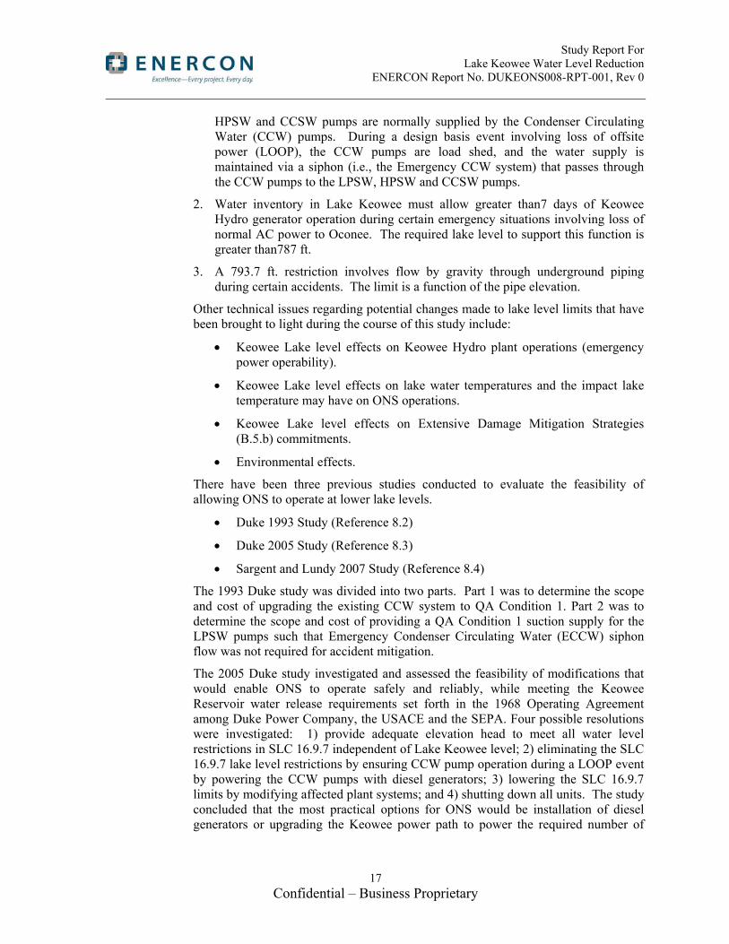
HPSW and CCSW pumps are normally supplied by the Condenser Circulating Water (CCW) pumps. During a design basis event involving loss of offsite power (LOOP), the CCW pumps are load shed, and the water supply is maintained via a siphon (i.e., the Emergency CCW system) that passes through the CCW pumps to the LPSW, HPSW and CCSW pumps.
2. Water inventory in Lake Keowee must allow greater than7 days of Keowee Hydro generator operation during certain emergency situations involving loss of normal AC power to Oconee. The required lake level to support this function is greater than787 ft.
3. A 793.7 ft. restriction involves flow by gravity through underground piping during certain accidents. The limit is a function of the pipe elevation.
Other technical issues regarding potential changes made to lake level limits that have been brought to light during the course of this study include:
Keowee Lake level effects on Keowee Hydro plant operations (emergency power operability).
Keowee Lake level effects on lake water temperatures and the impact lake temperature may have on ONS operations.
Keowee Lake level effects on Extensive Damage Mitigation Strategies (B.5.b) commitments.
Environmental effects.
There have been three previous studies conducted to evaluate the feasibility of allowing ONS to operate at lower lake levels.
Duke 1993 Study (Reference 8.2)
Duke 2005 Study (Reference 8.3)
Sargent and Lundy 2007 Study (Reference 8.4)
The 1993 Duke study was divided into two parts. Part 1 was to determine the scope and cost of upgrading the existing CCW system to QA Condition 1. Part 2 was to determine the scope and cost of providing a QA Condition 1 suction supply for the LPSW pumps such that Emergency Condenser Circulating Water (ECCW) siphon flow was not required for accident mitigation.
The 2005 Duke study investigated and assessed the feasibility of modifications that would enable ONS to operate safely and reliably, while meeting the Keowee Reservoir water release requirements set forth in the 1968 Operating Agreement among Duke Power Company, the USACE and the SEPA. Four possible resolutions were investigated: 1) provide adequate elevation head to meet all water level restrictions in SLC 16.9.7 independent of Lake Keowee level; 2) eliminating the SLC 16.9.7 lake level restrictions by ensuring CCW pump operation during a LOOP event by powering the CCW pumps with diesel generators; 3) lowering the SLC 16.9.7 limits by modifying affected plant systems; and 4) shutting down all units. The study concluded that the most practical options for ONS would be installation of diesel generators or upgrading the Keowee power path to power the required number of

Study Report For Lake Keowee Water Level Reduction ENERCON Report No. DUKEONS008-RPT-001, Rev 0
18 Confidential – Business Proprietary
CCW pumps necessary to supply the required net positive suction head (NPSH) to the LPSW, HPSW, and CCSW pumps during a LOOP.
The 2007 S&L study evaluated the two previous Duke studies to determine if the studies provided viable engineering options, if the studies considered all viable options available regardless of cost, and if the cost estimates provided in the Duke evaluations were reasonable Order of Magnitude estimates considering that no detailed engineering preliminary design had been performed. Additionally, the S&L study considered two other options not considered in the two previous Duke studies: replace HPSW and LPSW pumps with vertical pumps with their suctions at the buried CCW lines; and convert the intake canal into a perched lake (elevated, constant CCW level intake lake). The S&L study determined that the best course of action for Duke would be to continue to operate ONS with a Keowee lower lake level limit of 794 ft if the USACE and SEPA are agreeable. S&L determined that if maintaining the lower lake level limit of 794 ft was not achievable, then the only reasonable modification was to add diesel generators to power one CCW pump per unit and maintain Keowee above 787 ft to allow Keowee Hydro to cope with a 7 day LOCA/LOOP.
1.3 Bases for Lake Level Restrictions
Table 1-1 provides the current Keowee Lake Level restrictions from SLC 16.9.7 and the bases for the level restrictions.
Table 1-1
SLC 16.9.7 Keowee Lake Level Commitments (Reference 8.26)
Commit-ment
Condi-tion
Level Commitment System Commitment
a. A. Maintain lake level 793.7 ft to support CCW gravity induced reverse flow
With lake level below 793.7 ft, gravity induced reverse flow through the CCW discharge piping and through the Condensate Coolers cannot supply adequate flow to the suction of the LPSW pumps and [Standby Shutdown Facility] (SSF) [Auxiliary Service Water] (ASW) pump. See SLC 16.9.11 for additional information. (Note that commitment c of SLC 16.9.11 is not required to be met at lake levels below 793.7 ft). The licensing basis for Oconee takes credit for the SSF to mitigate a Turbine Building Flood, and there is no commitment to meet single failure criteria. However, maintaining the capability for decay heat removal using LPSW can reduce overall plant risk for some flood scenarios. There is no commitment to maintain the lake level above 793.7 ft at all times. The [Probabilistic Risk Assessment] (PRA) addresses the probability of lake levels below 793.7 ft, resulting in loss of gravity induced reverse flow capability. However, reducing the lake level below 793.7 ft

Study Report For Lake Keowee Water Level Reduction ENERCON Report No. DUKEONS008-RPT-001, Rev 0
19 Confidential – Business Proprietary
Table 1-1
SLC 16.9.7 Keowee Lake Level Commitments (Reference 8.26)
Commit-ment
Condi-tion
Level Commitment System Commitment
changes the risk levels associated with equipment out of service. Therefore, commitment a. is included as a means to ensure that the loss of gravity induced reverse flow capability is adequately addressed for equipment out of service, as required by the Maintenance Rule, 10 CFR 50.65, paragraph a(4).
b. B. Maintain lake level 793 ft when “A” HPSW Pump running or switch in BASE
With lake level below 793 ft, additional administrative controls are placed on HPSW pump alignment to prevent adversely affecting LPSW pump [net positive suction head] (NPSH). The worst case configuration for LPSW pump NPSH is the simultaneous operation of the "A" LPSW Pump, "B" LPSW Pump, and "A" HPSW Pump and a postulated single failure of the "C" LPSW Pump. This configuration is worst case because all operating pumps take suction from a common 36" supply header. At lake levels below 793 ft, adequate LPSW pump NPSH is maintained if the "B" HPSW pump is the first HPSW pump to start on low [Elevated Water Storage Tank] (EWST) level. With the "B" HPSW Pump switch in BASE, the pump starts upon EWST low level. With the "A" HPSW Pump switch in STANDBY, the pump starts upon EWST emergency low level.
With lake level below 793 ft and the “A” HPSW pump running or its switch in BASE, Unit 1 and 2 are in a condition where the LPSW System is vulnerable to single failure…
c. C. Maintain lake level 793 ft when “A” HPSW Pump is capable of auto-starting on low EWST level and the “B” HPSW Pump is inoperable, switch OFF or switch in STANDBY
With lake level below 793 ft, the “A” HPSW pump capable of auto-starting on low EWST level, and the “B” HPSW pump inoperable, switch OFF, or switch in STANDBY; Unit 1 and 2 are in a condition where the LPSW System is vulnerable to single failure…
d. D. Maintain lake level 792 ft to support CCW gravity induced reverse flow to the SSF service water pumps
If Keowee lake level is ≥ 792 ft and at least one gravity induced reverse flow path through the Unit 2 Condensate Cooler is aligned and OPERABLE to supply the Unit 2 CCW inlet pipe, gravity induced reverse flow is a viable method for supplying the SSF service water

Study Report For Lake Keowee Water Level Reduction ENERCON Report No. DUKEONS008-RPT-001, Rev 0
20 Confidential – Business Proprietary
Table 1-1
SLC 16.9.7 Keowee Lake Level Commitments (Reference 8.26)
Commit-ment
Condi-tion
Level Commitment System Commitment
pumps…
e. E. Maintain lake level 791 ft to assure that the "A" HPSW Pump shall be OPERABLE
With lake level below 791 ft, the "A" HPSW Pump must be declared inoperable… because the pump has inadequate NPSH during ECCW siphon flow mode…
f. E. Maintain lake level 791 ft to assure that the LPSW Pumps shall be OPERABLE.
With lake level below 791 ft, the LPSW pumps could experience inadequate NPSH during ECCW siphon flow mode if a single failure causes the loss of one required LPSW pump. The lake level limit also accounts for a postulated pipe break at a normally open seismic boundary valve. For Unit 1 and 2, the NPSH analysis assumes the "A" HPSW Pump is in STANDBY and the "B" HPSW Pump is in BASE. For Unit 3, the analysis assumes one HPSW pump is in operation. If all required LPSW pumps are available, adequate NPSH is available. Thus the Unit 1&2 and Unit 3 LPSW Systems are unable to withstand a single failure at lake levels below 791 ft…
g. F. Maintain lake level 790 ft to assure that the Chiller Condenser Service Water Pumps shall be OPERABLE
With lake level below 790 ft, the Chiller Condenser Service Water Pumps (CCSWPs) may be adversely affected because the potential exists for air to de-entrain during ECCW siphon flow mode. Since the CCSWPs support the Chilled Water (WC) System, both WC trains must be declared inoperable.
h. G. Maintain lake level 789 ft to assure that the "B" HPSW Pump shall be OPERABLE
With lake level below 789 ft, the "B" HPSW Pump must be declared inoperable because the pump has inadequate NPSH during ECCW siphon flow mode.
i. H. Maintain lake level 787 ft to prevent additional administrative controls on the Radwaste Equipment Cooling alignment
With lake level below 787 ft, all ECCW Siphon Headers aligned to the Radwaste Equipment Cooling System must be declared inoperable immediately due to potential air inleakage from non-seismic piping during ECCW siphon flow mode. Seismic boundary valves CCW-319 and CCW-320 shall be closed to maintain operability of the ECCW Siphon Headers.
j. H. Maintain lake level 787 ft to assure that adequate water supply shall be available for 7
With lake level below 787 ft, the water supply (for Keowee Hydro Station to provide emergency power to the overhead path at 42.8

Study Report For Lake Keowee Water Level Reduction ENERCON Report No. DUKEONS008-RPT-001, Rev 0
21 Confidential – Business Proprietary
Table 1-1
SLC 16.9.7 Keowee Lake Level Commitments (Reference 8.26)
Commit-ment
Condi-tion
Level Commitment System Commitment
days of Keowee emergency operation
MVA and the underground path at 22.35 MVA) could be inadequate for 7 days of continuous operation at these levels. Neither Keowee Hydro nor Oconee Nuclear Station should be considered inoperable at this lake level. Keowee Hydro should not generate to the grid at lake levels below 787 ft in order to ensure ample water capacity for emergency power operation.
k. I. Maintain lake level 786 ft to assure that the ECCW System shall be OPERABLE
With lake level below 786 ft, all ECCW Siphon Headers must be declared inoperable immediately because the ECCW test acceptance criteria would be invalid.
l. J. Maintain lake level 783 ft to assure that the Keowee Oil Storage Room Water Spray System shall be OPERABLE
Should lake level fall below 783 ft, the Keowee Oil Storage Room water spray system may not provide the required flow rates because the system is dependent on lake level for driving head. For this reason, the spray system must be declared inoperable.
m. K. Maintain lake level 780 ft to assure that the Keowee Step-up Transformer Mulsifyre System shall be OPERABLE
Should lake level fall below 780 ft, the Keowee main Step up Transformer Mulsifyre system may not provide the required flow rates because the system is dependent upon lake level for driving head. For this reason, the Mulsifyre should be declared inoperable.
2.0 Study Process Overview The overall process for the study is discussed in general below and in more detail in subsequent subsections (the process is illustrated in the flowchart in Figure 2-1).
After project award, information was gathered through a kickoff meeting, document searches, and walk-downs. Throughout the study, Duke Energy personnel participated in review meetings to validate study inputs and assumptions to assure the accuracy of the study.
Part 1 of the study evaluates the number of operating CCW pumps necessary to provide the required NPSH for the LPSW and HPSW systems at a Lake Keowee level of 787 ft msl for the condition of a site wide LOOP and a LOCA on one unit. The number of CCW pumps determined to be needed to supply the necessary NPSH is used to determine the power requirements for the CCW pumps during LOOP. Two methods of powering the CCW pumps are evaluated: installation of safety related diesel generators (DGs) and upgrade of the Keowee Hydro power path. For the diesel generator option, the number and type of diesel generators necessary to provide the power to the CCW pumps are specified, followed by a multi-discipline review of the proposed diesel generators. A Civil engineering evaluation identifies possible locations for the diesel generator buildings and for diesel fuel oil storage facilities. For evaluation of the possible locations for the diesel generator related facilities,
Study Report For Lake Keowee Water Level Reduction ENERCON Report No. DUKEONS008-RPT-001, Rev 0
22 Confidential – Business Proprietary
selection criteria are developed and used to rank the identified locations by both Civil and Electrical engineering. An Electrical engineering evaluation identifies the needed electrical support systems, cable routing, switchgear and controls for the diesel generators. A Mechanical engineering evaluation identifies the needed mechanical support systems, including heating, ventilation, and air conditioning (HVAC), fire protection, and starting air requirements. For the Keowee Hydro power path upgrade option, the modifications required to provide sufficient safety related power for the CCW pumps are identified by discipline. The multi-discipline evaluations are used to develop a scope summary for the required modifications necessary for each option. Finally, a licensing evaluation of the changes is performed to determine the impact to the existing licensing basis and to provide a preliminary assessment for the potential of a license amendment request.
To evaluate other possible levels for Lake Keowee, approximate hydraulic models are developed, or modified from existing models, for the LPSW, HPSW, and CCSW systems. Results are compared against existing flow models and plant test data. These models are used to evaluate flow reduction options in the LPSW, HPSW, and CCSW systems: however, they do not include the level of rigor required for safety-related calculations. The performance of pipe stress and pipe support calculations to determine the impact of piping temperature changes is not within the scope of this study. Evaluations and cost estimations to upgrade or replace heat transfer equipment is not within the scope of this study.
Evaluation of the impact on the lake temperatures due to decreased water levels and the impact on pump net positive suction head calculations is qualitatively discussed, but not quantified. Similarly, permitting and security requirements for new diesel generator locations are qualitatively discussed.
Part 2 of the study evaluates the feasibility of adding diesel generators so that emergency power is not required from Lake Keowee Hydro. The site emergency power requirements are evaluated to differentiate between loads required to meet the licensing basis for the plant (i.e., safety related loads) and those loads needed to cope with a loss of offsite power (i.e., non-safety related loads). The power requirements for each of the two load groups are used to specify the number and type of diesels needed, followed by a multi-discipline evaluation similar in scope to the diesel generator evaluation in Part 1. Scope summaries are developed for the required modifications. Additionally, Part 2 evaluates the impact of reducing lake level and the elimination of reliance on Keowee Hydro on the design/licensing basis for the new PSW system.
The required modifications for Part 1 and for Part 2 are reviewed for feasibility and for impacts to current ONS licensing requirements. Cost estimates are developed for design, material, installation, and operations and maintenance (O&M) costs. Cost estimates are also provided for activities associated with Environmental permitting requirements and control room habitability issues from diesel generator emissions.

Study Report For Lake Keowee Water Level Reduction ENERCON Report No. DUKEONS008-RPT-001, Rev 0
23 Confidential – Business Proprietary
Figure 2-1, Study Process Flowchart

Study Report For Lake Keowee Water Level Reduction ENERCON Report No. DUKEONS008-RPT-001, Rev 0
24 Confidential – Business Proprietary
2.1 Study Process for Part 1 – Evaluation of Design Changes for Operation at 787 feet msl
There are three options (1a, 1b & 1c) considered for ONS operation at a lake level of 787 ft msl.
Part 1 Options 1a and 1c evaluate the feasibility to use CCW pumps to provide the required NPSH requirements for LPSW, HPSW and CCSW during loss of offsite power conditions, thus eliminating dependence on a minimum lake level to provide the ECCW siphon via the CCW system. For the Part 1 Options 1a and 1c, the number of required CCW pumps to provide the necessary NPSH must be determined. Once the number of pumps is determined, then the feasibility of upgrading the pumps, the pump motors, the pump discharge valves, and the valve operators/motors to QA1 must be evaluated. Additionally, the feasibility of upgrading the discharge valves and motors of the CCW pumps not being credited to QA1 must be evaluated since they must also close on loss of power to prevent backflow through the idle pumps. To power the credited CCW pumps’ motors and the discharge valve motors, safety-related power must be made available. The current safety-related power supply from Keowee Hydro via the underground line from transformer CT-4 is insufficient to power this additional load. Keowee Hydro power can be used, if additional conductors and transformer capacity was added (Part 1 Option 1c). This option is developed further in Activity #10. Alternatively, safety related diesel generators are also proposed as a means to power the additional load (Part 1 Option 1a). Activities 1 through 6, 10 and 11 address these two options.
Part 1 Option 1b evaluates the feasibility of reducing the flow required by the LPSW and HPSW systems by eliminating flow to non-essential loads and/or limiting flow to essential loads. This option would reduce the required NPSH for the LPSW and HPSW systems, if the necessary flow reductions are achieved. To reduce or eliminate the lake level restrictions currently imposed on the CCSW system (LLC 16.9.7.g), the study initially considered modifying the water source for CCSW from CCW to LPSW essential header. However, it was determined this modification would result in an increase to flow requirements for LPSW, and subsequently increase the minimum required lake level. The feasibility of installing a booster pump to provide additional head to the CCSW pumps was added to the scope of this study. This option is addressed in Activities 7, 8, 9 and 11.
Activity #1: Verify the Operation of Condenser Circulating Water (CCW) Pumps Provides Adequate Suction Head (Part of Part 1 Options 1a & 1c)
This portion of the study evaluates the impacts to flow rates and available Net Positive Suction Head (NPSH) for LPSW and HPSW pumps, with Lake Keowee level starting at 787 ft msl. The number of CCW pumps required to be operating and the number of CCW discharge valves that are needed to be operated are determined through this analysis.
Activity #2: Size and Location of New Diesel Generators to Power CCW Pumps (Part of Part 1 Option 1a)
To accomplish this task, the size and location of new diesel generators to be used as emergency power for the CCW pump motors and CCW pump discharge valve operator motors in the event of a LOCA and loss of offsite power on one unit and loss of offsite power on the other two units is determined. A review of the required

Study Report For Lake Keowee Water Level Reduction ENERCON Report No. DUKEONS008-RPT-001, Rev 0
25 Confidential – Business Proprietary
electrical load to power the pump and valve motors and the diesel generator auxiliaries is used to determine the required diesel generator capacity. An assessment of available site locations is based on an evaluation of the logistics and physical characteristics of each potential site. Site selection criteria are developed and each site considered is evaluated against the criteria to determine the optimum site(s). Cost estimates are developed for design, procurement, installation, and testing for the recommended site. Additionally, the cost of the design and construction of the structures to house the diesel generators are developed.
Activity #3: Diesel Generator Support Systems and Equipment Required (Part of Part 1 Option 1a)
All systems and equipment required to support the operations of diesel generators in Activity #2 above are identified. Preliminary sizing of support systems and equipment and order of magnitude cost estimates for design, procurement, installation, and testing for the support systems are developed. Support systems include, at a minimum, electrical distribution, instrumentation and controls, diesel fuel oil fill/storage/distribution, diesel starting air, lube oil, cooling water (external cooling water or self-contained radiators), intake and exhaust, batteries, fire suppression and detection, ventilation (for diesel building HVAC and control of hydrogen gas generated from batteries), and diesel fuel oil spill prevention controls and countermeasures (SPCC).
Activity #4: Upgrade CCW Pumps and Motors to QA1 (Part of Part 1 Options 1a & 1c and Part 2 Options 1 & 2)
Two options for upgrading the CCW pumps and motors to meet nuclear safety related (QA1) requirements are considered: (1) commercial-grade dedication of new CCW pumps and motors, or (2) design, procurement, and installation of new nuclear safety related (QA1) pumps and motors. Design requirements, specifications, safety and functional requirements, interface requirements, etc. that are necessary to produce dedication packages or procurement specifications will be based on current plant drawings, calculations, and system design basis documents. For the first option, a plan is outlined for the process by which new CCW pumps and motors can be obtained via commercial grade dedication. Cost and schedule estimates are provided for this option. For the second option, potential vendors are identified, cost estimates solicited, and schedules outlined.
Activity #5: Upgrade of CCW Pump Discharge Valves to QA1 (Part of Part 1 Options 1a & 1c and Part 2 Options 1 & 2)
Similar to the CCW pumps and motors, two options for upgrading the CCW pump discharge valves to meet nuclear safety related (QA1) requirements are considered: (1) commercial-grade dedication of new valves and operators, or (2) design, procurement, and installation of new nuclear safety related (QA1) valves and operators. Design requirements, specifications, safety and functional requirements, interface requirements, etc. that are necessary to produce dedication packages or procurement specifications will be based on current plant drawings, calculations, and system design basis documents. For the first option, a plan is outlined for the process by which new CCW pump discharge valves and operators can be obtained via commercial grade dedication. Cost and schedule estimates are provided for this

Study Report For Lake Keowee Water Level Reduction ENERCON Report No. DUKEONS008-RPT-001, Rev 0
26 Confidential – Business Proprietary
option. For the second option, potential vendors are identified, cost estimates solicited, and schedules outlined.
Activity #6: Determine if Upgrades are Needed to Existing Cables or Cable Routes (Part of Part 1 Options 1a & 1c and Part 2 Options 1 & 2)
Power, instrumentation and control cable separation requirements must be addressed in order to upgrade the component qualification (discussed in Tasks 4 and 5) to safety related, as well as the actual upgrading the cable. Alternate routing to meet separation requirements are proposed and shown on sketches as part of this task. Replacement cable to meet applicable qualification requirements is researched and recommendations made.
Raceway and raceway supports, along with the cables, are required to be upgraded to safety related in order to meet plant requirements for such design.
The estimated cost of replacing existing cables and/or adding, new power and control cables will be identified in the water level reduction study. The estimates will consider material costs, installation costs, and engineering costs.
Several of the Plant modifications described by the water level reduction study will increase combustible inventories in the Plant. The study will identify the potential cost(s) associated with the review/revision of the combustible loading calculation and the review of the fire barriers. The actual review/revision of the calculations will be done when the Plant modifications are approved for implementation.
Activity #7: Evaluate Modifications to Limit Flow to LPSW Loads (Part of Part 1 Option 1b)
For each LPSW load, the current flow rate and the minimum required flow rate for the LOOP/LOCA event is determined. With all LPSW loads reduced to their minimum required flow rate, the reduction in required net positive suction head for the LPSW pumps, and the allowed Lake Keowee level is determined. Alternatives to limit flow to the LPSW loads with the largest difference between current and minimum required flow rates are identified. Estimates for design, procurement, installation and operations and maintenance costs for the optimum alternatives are provided.
Activity #8: Evaluate Modifications to Limit Flow to HPSW Loads (Part of Part 1 Option 1b)
For each HPSW load, the current flow rate and the minimum required flow rate for the LOOP/LOCA event is determined. With all HPSW loads reduced to their minimum required flow rate, the reduction in required net positive suction head for the HPSW pumps, and the allowed Lake Keowee level is determined. Alternatives to limit flow to the HPSW loads with the largest difference between current and minimum required flow rates are identified. Estimates for design, procurement, installation and operations and maintenance costs for the optimum alternatives are provided.
Activity #9: Modifications to Chiller Condenser Service Water Pump Supply Line (Part of Part 1 Option 1b)
Options to allow LPSW to supply the CCSW Pumps while isolating non-essential loads are evaluated. In order to evaluate the feasibility of this concept, it is necessary

Study Report For Lake Keowee Water Level Reduction ENERCON Report No. DUKEONS008-RPT-001, Rev 0
27 Confidential – Business Proprietary
to determine the impact on suction head and flow requirements. Preliminary calculations concluded that tie-in of the CCSW pump supply line to LPSW essential header would actually require an increase to the minimum lake level because it increases flow demands on the LPSW system. Therefore, this activity was modified to consider the feasibility of installing a booster pump in the existing CCSW pump supply line in an effort to increase available NPSH to the CCSW pumps. Estimates for design, procurement, installation, and operations and maintenance costs for this alternative are provided.
Activity #10: Upgrade to the Keowee Hydro Power Path to Power CCW Pumps (Part of Part 1 Option 1c)
To accomplish this task, the necessary upgrades to the Keowee Hydro power path to be used as emergency power for the CCW pump motors and CCW pump discharge valve operator motors in the event of a LOCA and loss of offsite power on one unit and loss of offsite power on the other two units is determined. A review of the required electrical load to power the pump and valve motors and any additional Keowee Hydro and/or new transformer loads are used to determine the required additional Keowee Hydro safety related transmission capacity. An assessment of available ductbank routing between Keowee Hydro and the CCW pumps and site locations for switchgear and transformer are based on an evaluation of the logistics and physical characteristics of each potential site. Site selection criteria are developed and each site considered is evaluated against the criteria to determine the optimum site. Cost estimates are developed for design, procurement, installation, and testing. Additionally, the cost of the design and construction of the ductbank and structures to house the switchgear and transformer are developed.
Activity #11: Provide Detailed Evaluation of Feasibility of Alternatives (For Part 1 Options 1a, 1b, & 1c)
The study includes a feasibility evaluation of modifications to provide safety related diesel generator or upgraded Keowee Hydro backup power to CCW pump motors, CCW pump discharge valve actuator motors and instrumentation to ensure CCW flow to essential loads required for safe shutdown following a LOCA concurrent with a loss of power for one unit and loss of offsite power on the other two units. Items considered are: ability to achieve lake level of 787 ft msl, plant conditions required for implementation, licensing feasibility and licensing document impacts, impacts to control room habitability resulting from diesel exhaust fumes, other significant constraints, limitations, assumptions, and risks.
2.2 Study Process for Part 2 – Evaluation of Design Changes for Operation at 777.1 feet msl
Part 2 of the study evaluates the feasibility of adding diesel generators so that emergency power is not required from Lake Keowee Hydro. The site emergency power requirements are evaluated to differentiate between loads required to meet the licensing basis for the plant (i.e., safety related loads), those loads needed to cope with a loss of offsite power (i.e., non-safety related loads), and those loads required to support operation of the Protected Service Water (PSW) system. The power requirements for each of the load categories are used to specify the number and type of diesels needed, followed by a multi-discipline evaluation similar in scope to the diesel generator evaluation in Part 1.

Study Report For Lake Keowee Water Level Reduction ENERCON Report No. DUKEONS008-RPT-001, Rev 0
28 Confidential – Business Proprietary
Activity #1: Size and Location of New Diesel Generators to Replace Keowee Hydro
Two options are considered for this task: (1) evaluation of diesel generator capacity necessary to supply the licensing basis electrical loads (i.e., safety related emergency loads and PSW loads only); and (2) evaluation of diesel generator capacity necessary to supply the beyond design basis electrical loads (i.e., safety related emergency loads and PSW loads plus other non-emergency loads that currently are capable of being supplied by the overhead lines from Keowee Hydro). Part 2 Option 1 would eliminate the reliance on Keowee Hydro for emergency power for safety related and PSW system loads in the event of a loss of offsite power. Part 2 Option 2 would eliminate the reliance on Keowee Hydro for emergency power for all equipment that currently can be fed from the hydro plant in the event of a loss of offsite power.
To accomplish this task, the size and the location of new diesel generators to be used as emergency power for site equipment in the event of a loss of offsite power is determined. A review of electrical requirements to power the two options considered and the diesel generator auxiliaries is used to determine the required diesel generator capacity. An assessment of available site locations is based on an evaluation of the logistics and physical characteristics of each potential site. Site selection criteria are developed and each site considered is evaluated against the criteria to determine the optimum site(s). Cost estimates for design, procurement, installation, and testing for the recommended sites. Additionally, the cost of the design and construction of the structures to house the diesel generators and support equipment (e.g., transformers) are developed.
Activity #2: Diesel Generator Support Systems and Equipment Required
Similar to Activity #3 for Part 1, all systems and equipment required to support the operations of diesel generators identified in Activity #1 are identified and preliminary sizing and cost estimates of support systems and equipment are developed.
Activity #3: Provide Detailed Evaluation of Feasibility
The study includes a feasibility evaluation of modifications to provide safety-related backup power via diesel generators to ONS. Items considered are: ability to achieve lake level of 777.1 ft msl, plant conditions required for implementation, licensing feasibility and licensing document impacts, impacts to control room habitability resulting from diesel exhaust fumes, significant constraints, limitations, assumptions, and risks.
3.0 Evaluations
3.1 Part 1 – Operation at Lake Level of 787 feet msl
As discussed in Section 2.1 above, there are eleven distinct activities associated with this part of the study. The evaluations associated with each of the eleven activities are discussed in detail below:

Study Report For Lake Keowee Water Level Reduction ENERCON Report No. DUKEONS008-RPT-001, Rev 0
29 Confidential – Business Proprietary
3.1.1 Activity #1: Verify the Operation of Condenser Circulating Water (CCW) Pumps Provides Adequate Suction Head (Part of Part 1 Options 1a & 1c)
Task Summary
Evaluate the impacts to flow rates and available NPSH for the LPSW and HPSW pumps with the Lake Keowee level starting point at 787 feet msl. The number of CCW pumps required for such operation and the number of CCW discharge valves that are needed to be operated must also be determined.
Evaluation
The following design solution was identified for this activity:
Conceptual Design Description
Assuming normal plant operations at a target lake level of 787 feet and considering lake level drawdown during and following an accident, a final lake level of 777.1 feet msl is assumed while using Keowee Hydro Units for emergency power. Calculation OSC-3528 was reviewed to determine lake level drawdown following an accident. For the most conservative loading of the hydro unit with the CT-4 transformer fully loaded, the lake level drops approximately 10 feet over the course of 7 days, starting from a lake level of 787 feet msl at the beginning of the accident.
The LPSW, HPSW, and CCSW pumps take suction from a common CCW cross-connect header. Based upon the proposed emergency power design, the availability of two additional pumps would be required to meet single failure criteria. To provide additional flexibility for operations, the remaining CCW pumps can be upgraded as well. Therefore, all twelve CCW pumps and their respective discharge valves and operators should be upgraded to QA-1 status and be provided with QA-1 power and controls (see Activities 4 and 5). Those portions of the SSW system providing sealing and cooling water for these pumps have already been upgraded to QA-1 status. The diesel generators required to power the CCW pumps, discharge valves and controls will be sized to carry four CCW pumps per unit. This solution does not change any of the flow rates required to the LPSW, HPSW, or CCSW systems.
Functional Design Assessment
In order to replace the siphon, this solution must provide adequate flow rate and NPSH to the LPSW, HPSW and CCSW pumps during a LOOP event. The current flow rate required of the siphon is 91,200 gpm per calculations OSC-5670 (Reference 8.27) and OSC-5349 (Reference 8.28). This flow rate consists of the following:
30,000 gpm for emergency discharge flow
36,000 gpm for the Units 1 and 2 LPSW pumps (3 pumps at 12,000 gpm each)
10,000 gpm for the Unit 3 LPSW pump
14,000 gpm for both HPSW pumps

Study Report For Lake Keowee Water Level Reduction ENERCON Report No. DUKEONS008-RPT-001, Rev 0
30 Confidential – Business Proprietary
~1200 gpm for a single CCSW pump
The initial assessment to determine the minimum number of CCW pumps necessary for operation set the emergency discharge flow at 0 gpm since this flow path is no longer necessary to maintain the siphon. To set emergency discharge flow to 0 gpm, the model assumes that valves 1-CCW-1 through -6 are closed, and CCW-8 is open. HPSW flow rate is decreased to 6,000 gpm by removing unnecessary conservatism as described in OSC-5349 (Reference 8.28). This yields a minimum required flow rate for CCW pump operation during a LOOP event of 53,200 gpm. The CCW system is normally operated with a minimum of two pumps per unit (Reference 8.41).
To evaluate the effects of CCW pump operation on LPSW, HPSW, and CCSW pump NPSH, the CCW hydraulic model, developed within calculation OSC-4292, Reference 8.42, has been modified to reflect the service water requirements and conditions for a Licensing Basis LOCA in one unit and a Loss of Offsite Power for all three units. The model has been modified as follows:
The valves leading from each unit to the CCW cross-connect header have been opened.
The LPSW suction lines have been added at the appropriate nodes within the model to account for the hydraulic losses between where the CCW model left off and the pump impeller inlet.
The HPSW, LPSW, and CCSW pump flow rates have been modified to reflect the most limiting case (Data Set #3) within the LPSW NPSH calculation (Reference 8.9).
The discharge valve of each CCW pump has been opened/closed as necessary for pump operation.
For each number of pumps running (from one pump to twelve pumps), the minimum acceptable lake level is determined using the NPSH available calculated from the modeled suction pressure at the LPSW impeller inlet. The NPSH available is calculated using the same methodology as shown in OSC-2280 (Reference 8.9) without correcting for the pressure gauge location or elevation since the model provides suction pressure directly at the pump impeller. Several additional head loss terms have been included in the calculated NPSH available to account for flow resistances and other corrections not present in the current model. These additional head loss terms include:
CCW Strainer head loss of 4 feet (conservatively doubled from the strainer head loss used within OSC-2280)
Lake level uncertainty of 1 foot (consistent with OSC-2280)
Additional margin of 2 feet to account for model inaccuracies
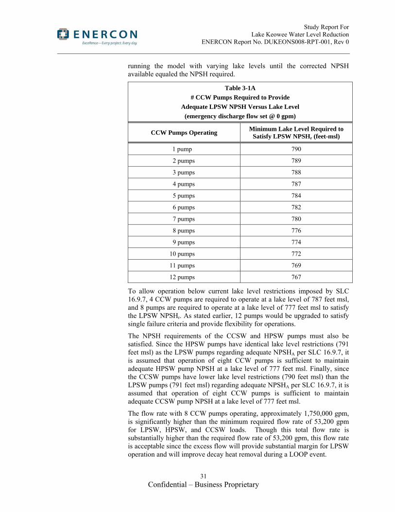
Table 3-1A shows the acceptable lake level calculated for each number of CCW pumps operating. Each lake level was determined by iteratively
Study Report For Lake Keowee Water Level Reduction ENERCON Report No. DUKEONS008-RPT-001, Rev 0
31 Confidential – Business Proprietary
running the model with varying lake levels until the corrected NPSH available equaled the NPSH required.
Table 3-1A
# CCW Pumps Required to Provide
Adequate LPSW NPSH Versus Lake Level
(emergency discharge flow set @ 0 gpm)
CCW Pumps Operating Minimum Lake Level Required to
Satisfy LPSW NPSHr (feet-msl)
1 pump 790
2 pumps 789
3 pumps 788
4 pumps 787
5 pumps 784
6 pumps 782
7 pumps 780
8 pumps 776
9 pumps 774
10 pumps 772
11 pumps 769
12 pumps 767
To allow operation below current lake level restrictions imposed by SLC 16.9.7, 4 CCW pumps are required to operate at a lake level of 787 feet msl, and 8 pumps are required to operate at a lake level of 777 feet msl to satisfy the LPSW NPSHr. As stated earlier, 12 pumps would be upgraded to satisfy single failure criteria and provide flexibility for operations.
The NPSH requirements of the CCSW and HPSW pumps must also be satisfied. Since the HPSW pumps have identical lake level restrictions (791 feet msl) as the LPSW pumps regarding adequate NPSHA per SLC 16.9.7, it is assumed that operation of eight CCW pumps is sufficient to maintain adequate HPSW pump NPSH at a lake level of 777 feet msl. Finally, since the CCSW pumps have lower lake level restrictions (790 feet msl) than the LPSW pumps (791 feet msl) regarding adequate NPSHA per SLC 16.9.7, it is assumed that operation of eight CCW pumps is sufficient to maintain adequate CCSW pump NPSH at a lake level of 777 feet msl.
The flow rate with 8 CCW pumps operating, approximately 1,750,000 gpm, is significantly higher than the minimum required flow rate of 53,200 gpm for LPSW, HPSW, and CCSW loads. Though this total flow rate is substantially higher than the required flow rate of 53,200 gpm, this flow rate is acceptable since the excess flow will provide substantial margin for LPSW operation and will improve decay heat removal during a LOOP event.

Study Report For Lake Keowee Water Level Reduction ENERCON Report No. DUKEONS008-RPT-001, Rev 0
32 Confidential – Business Proprietary
In order to pass this large amount of CCW flow, the normal flow path of the CCW system via the condenser and out the discharge canal must be open. Per Reference 8.31, the condenser discharge valves, 1/2/3-CCW-20/21/22/23/24/25, are air operated valves which fail as-is upon loss of instrument air during a LOOP. According to the CCW Operating Procedure, Reference 8.41, and the CCW Design Basis Specification, Reference 8.31, all of these valves for a particular unit automatically open once one CCW pump is started. Additionally, the operator must confirm that these are open immediately after start-up of the CCW pumps. Therefore, these valves are expected to be open under normal operating conditions. In the event of a loss of power to the air compressors (e.g., upon a LOOP event), these valves would fail in the “as-is” condition, which would be the open position. This would allow for the normal CCW flow path through the condenser to be available following a LOOP, thereby assuring an adequate flow path for the large CCW flow rate post-LOOP-LOCA.
However, control logic for condenser discharge valves would try to close the valves due to loss of power to the CCW pumps (such as during a LOOP event). It is beyond the scope of this study to determine which logic path would ultimately determine position of the condenser discharges valves. Therefore, it may be necessary to install safety-related actuators on these valves, either safety-related AOV operators with associated air accumulators or safety-related MOV operators. Cost and feasibility of this alternative is not within the scope of this report. The additional cost of either of these two modifications would be a very small percentage of the total cost of the options (Part 1 Options 1a and 1c, and Part 2 Options 1 and 2) that provide safety-related power to the CCW pumps.
Since this flow path overlaps the flow path for the second siphon, the emergency discharge flow path from the condenser outlet would need to be closed. The second siphon is no longer needed following a LOOP since full CCW flow will be available to remove decay heat through the condenser.
ENERCON was requested to add the 30,000 gpm emergency discharge flow back into the model, to determine what impact it would have on the required number of CCW pumps needed to operate as lake level decreases. To set emergency discharge flow to 30,000 gpm, the model assumes that valves 1-CCW-1 through -6 are open, CCW-9 is closed, and CCW-8 is open. The results of this scenario are presented in Table 3-1B below.

Study Report For Lake Keowee Water Level Reduction ENERCON Report No. DUKEONS008-RPT-001, Rev 0
33 Confidential – Business Proprietary
Table 3-1B
# CCW Pumps Required to Provide Adequate
LPSW NPSH Versus Lake Level
(emergency discharge flow set @ 30,000 gpm)
# CCW Pumps Operating Minimum Lake Level Required to
Satisfy LPSW NPSHr (feet-msl)
1 pump 790
3 pumps 789
4 pumps 788
5 pumps 784
6 pumps 782
7 pumps 780
8 pumps 776
9 pumps 774
10 pumps 772
11 pumps 769
12 pumps 767
Adding the 30,000 gpm emergency discharge flow back into the model changes the number of CCW pumps required to operate at lake levels of 789’ and 788’; however, it does not affect the number or size of the emergency diesel generators that are required for Options 1-1a, 2-1, or 2-2.
Identified Issues
Several obstacles must be overcome if CCW pump operation is used to supply LPSW, HPSW and CCSW during a LOOP/LOCA event. Timing of pump start-up is crucial to ensure that cooling capacity is provided in time for the various plant loads experienced following an accident.
A review of various site documents (UFSAR, Design Basis Documents (DBD), Event Mitigation Calculations, etc.) was performed to establish a timeline of events that occur during a Licensing Basis LOCA in one unit and a Loss of Offsite Power for all three units.
As noted in the Design Basis Document for the 4KV Essential Auxiliary Power System (Reference 8.43), power is available within 33 seconds of event initiation (time required for Keowee Hydro to energize the safety related busses) allowing the LPSW pumps to be running at rated speed and pressure at approximately the 33 second point (or earlier) after a LBLOCA or LOOP. Sufficient NPSH must be available for the LPSW pumps. The NPSH is currently supplied by the 1st Siphon with no CCW pumps running; however, if Lake Keowee level is to be reduced to as low as 787 ft then it
Study Report For Lake Keowee Water Level Reduction ENERCON Report No. DUKEONS008-RPT-001, Rev 0
34 Confidential – Business Proprietary
may be necessary to be able to start CCW pumps to supply the NPSH. In addition to needing an emergency power supply, the following issue must be addressed:
For the current plant configuration, in order to start a CCW pump when no CCW pumps are running (i.e. during a LOOP) the discharge valves of both pumps on one CCW inlet header must be closed. The discharge valves could be in the open position until the 33 second point (when the Keowee Hydro units get up to speed and the emergency busses are ready to be loaded) because of the loss of power to the discharge valves at the beginning of the event. When the emergency busses are re-energized, the valve will travel fully closed. The closing stroke time is approximately 76 seconds (OSC-5760, Reference 8.29). The discharge valve is automatically opened for the start-up pump. As the discharge valve reaches approximately 20% open, the breaker to the pump will close, and the pump and valve will proceed to normal operation and the fully open position respectively (CCW DBD, Reference 8.31). Therefore, the CCW pump would not be able to supply adequate NPSH in this situation until approximately 124 seconds after the start of the event assuming power is supplied by the Keowee Hydro unit. This time would be reduced to approximately 101 seconds if diesel generators were employed to supply the emergency power, since a typical emergency diesel generator start time is ≤10 seconds.
In order to speed up CCW availability to feed the LPSW system, the following options may decrease the amount of time required to get the CCW pumps operating:
1. In order to improve timing, the valve control sequence could be altered to close only to the 20% position required for pump start-up (saving approximately 30 seconds; i.e., eliminate the 15 seconds required to go from 80% closed to full closed and the 15 seconds required to go from full closed back to 20% open).
2. The valve operator could be modified to include a pneumatic actuator in combination with air accumulators to allow for immediate actuation upon a LOOP event (i.e., to eliminate the delay due to Keowee Hydro (33 seconds) or diesel generator (10 seconds) start time). A more powerful actuator could be specified which allows for significantly shorter stroke time of the valve (this time savings has not been established).
3. Alternatively, the valve motor operators could be provided with a standby uninterruptable power supply (UPS) system which could allow for immediate actuation upon a LOOP event (i.e., to eliminate the delay due to Keowee Hydro or diesel generator start time, approximately 33 seconds for the hydro unit or 10 seconds for the diesel generator).
4. LPSW supply to HPI pump motor bearing cooling could be provided with a reservoir in combination with a vacuum breaker to provide a short term water supply to the bearing until CCW pumps are operating.
A solution to this issue would likely involve some combination of these options. Additionally, the final timing for the restart of the CCW pumps

Study Report For Lake Keowee Water Level Reduction ENERCON Report No. DUKEONS008-RPT-001, Rev 0
35 Confidential – Business Proprietary
would also apply to the LPSW pumps since they require sufficient NPSH (supplied by CCW) for restart. The delayed start of LPSW pumps may impact the ability of the LPSW Water Hammer Prevention System to fulfill its design function, requiring potential design change to allow it to accommodate the extended time delay. The delayed start of LPSW pumps would also necessitate the study of how other systems relying on cooling water of LPSW are impacted. Detailed planning, scoping, cost estimation, and design of these solutions are beyond the scope of this report, but it would need to be considered within the detailed design of this project.
3.1.2 Activity #2: Size and Location of New Diesel Generators to Power CCW Pumps (Part of Part 1 Option 1a)
Task Summary
Determine the size and location of new diesel generators to be used as emergency power for the CCW pump motors and CCW pump discharge valve operator motors in the event of a LOCA and loss of offsite power on one unit and a loss of offsite power on the other two units.
Evaluation
Diesel Generator Sizing
From Activity #1 above it was determined that site wide, eight CCW pumps are required to operate to provide the necessary NPSH for the LPSW, HPSW and CCSW pumps assuming a site wide loss of offsite power (LOOP) and a LOCA on one unit. However, even though only eight pumps are required to provide necessary NPSH, Activity #1 established that “all twelve CCW pumps and their respective discharge valves and operators should be upgraded to QA-1 status and be provided with QA-1 power and controls”. Because of this, all twelve pumps and their respective discharge valves and operators will have the capability of being powered from the safety related diesels. A three diesel generator approach is proposed to meet the emergency power requirements of the CCW pumps (see Figure 3-1).

Study Report For Lake Keowee Water Level Reduction ENERCON Report No. DUKEONS008-RPT-001, Rev 0
36 Confidential – Business Proprietary
Figure 3-1, Part 1 Option 1a CCW DG Configuration

Study Report For Lake Keowee Water Level Reduction ENERCON Report No. DUKEONS008-RPT-001, Rev 0
37 Confidential – Business Proprietary
The diesel generators are sized for N+1 redundancy. That is, each diesel generator is sized to carry half of the required load, or four CCW pumps, their discharge valves, diesel generator auxiliaries, and diesel generator building support systems. The proposed electrical configuration (see Figure 3-1) would allow for automatic transfer to the diesel generator for any selected CCW pump. It is designed for emergency power to be provided by two diesel generators, with the capability to switch to the backup diesel generator if one of the primary diesel generators fails. The CCW pump motors are rated at 1750 horse power each which is equivalent to approximately 1535 kW. This primary load and additional loads have been estimated in Table 3-2 below:
Table 3-2
Electrical Load Capacity for CCW Pump DGs (Part 1 Option 1a)
Load kw Qty (min
load) Total kW (min load)
Qty (max load)
Total kW (max load)
CCW pump 1535 2 3070 4 6140
Discharge Valves
7.5 2 15 4 30
DG auxiliaries 75 1 75 1 75
DG building support
60 1 60 1 60
Total 3220 6305
A diesel generator has been selected with a capacity of 6750kWe. This allows for fully loaded service at 4 pumps operating, and acceptable load on the diesel generator with as few as 2 pumps running. This allows for a total of as few as 2 pumps running up to the maximum of 8 (four per diesel).
Table 3-3 shows valid breaker configurations for each pair of primary diesel generators in operation where “X” = breaker closed and “O” = breaker open.
Table 3-3
Part 1 Option 1a CCW DG Breaker Alignment Matrix
PRI GEN 1A 1T 1B 2A 2T 2B 3A 3T 3B
A&B O X X X O X X X O
A&C X O X X X O O X X
B&C X X O O X X X O X
Two US manufacturers that currently supply diesel generators for nuclear safety related service were investigated as to their suitability for the application. Fairbanks Morse was selected to use for this study, primarily

Study Report For Lake Keowee Water Level Reduction ENERCON Report No. DUKEONS008-RPT-001, Rev 0
38 Confidential – Business Proprietary
because they had a broader range of models available in the sizes needed. Fairbanks Morse Engine (FME) also provided more complete information for the required sizes.
Refer to Attachment 1 for information and pricing provided by Engine Systems, Inc. (ESI). Attachment 2 contains information and pricing provided by Fairbanks Morse.
Siting of Diesel Generators
An assessment of available site locations was based on an evaluation of the logistics and physical characteristics of each potential site. Site selection criteria were developed and each site considered was evaluated and ranked using the criteria to determine the optimum site(s).
Eight sites were considered for possible diesel generator locations. Seven of the possible sites were located within the current Owner Controlled Area (OCA) and one site was adjacent to the OCA across highway 183. Of the seven sites inside the OCA two were located within the existing Protected Area (PA) perimeter. Of the eight sites considered, two sites were selected as the primary sites of interest with one site recommended overall. See Attachment 3 for the location of the potential sites considered.
The sites were ranked based on criteria including, but not limited to, the following:
Location
Proximity to terminus of loads
Security
o Vulnerability of duct bank
o Ability to construct new diesel buildings outside of the security perimeter, then move the fence
o Currently located inside security perimeter
Flood requirements
Exhaust fume impacts (including control room habitability)
Soil conditions
Impact on surrounding structures and their operational ability
Impact on plant personnel
Retaining structures required
Size of building
Permitting
Environmental Impact

Study Report For Lake Keowee Water Level Reduction ENERCON Report No. DUKEONS008-RPT-001, Rev 0
39 Confidential – Business Proprietary
Civil Site Evaluation Discussion
The following is an assessment of each of the eight sites based on civil considerations:
Site #1
Resides closely to an existing electrical pathway from Keowee Hydro, but is far away from the CCW pumps and the electrical trench is full according to Oconee’s original design criteria
No impact on surrounding buildings
Requires a new protected area away from the existing PA
Removes an existing parking lot
Subject to complete destruction due to “External Flood Event”
Close to FERC Boundary – additional permitting required
Requires hazardous substance permit due to the parking lot being the cap for the site’s previous sewage waste
Site #2
Subject to complete destruction due to “External Flood Event”
Resides close to the CCW pumps and existing duct bank to the current bus
Impacts the PSW ductbank
Requires an extension of the existing PA
Very small site
Soil is saturated due to seepage from lake above
Site #3
Location is outside of the OCA
Requires a new protected area away from the existing PA
Connecting the site to the plant would be very difficult and costly
No impact on surrounding structures
May conflict with possible new power plant construction
Site #4
Location is near the CCW pumps
Flexibility such that the main construction activities would occur outside of the PA followed by an expansion of the existing PA to incorporate the new building
No impact on existing surrounding structures
Limits expansion capability of existing ISFSI to the north, but would not interfere with current plans to expand the ISFSI to the west
Removes current site dumping ground for soil

Study Report For Lake Keowee Water Level Reduction ENERCON Report No. DUKEONS008-RPT-001, Rev 0
40 Confidential – Business Proprietary
Extensive grading and drainage
Above “External Flood Event” water levels
Site #5
Location is inside the existing PA
No security modifications required
Requires the removal of an existing warehouse
Adversely impacts control room habitability
Limits storage area and staging area inside PA
Costs will probably be associated with contaminated material disposal if any demolition is required
Site #6
Location is inside the existing PA
Area inside of PA is already being looked at for water storage & Appendix R Warehouse.
No security modifications required if area maintained within PA boundary
Adversely impacts control room habitability
Requires extensive soil removal
No impact on existing surrounding structures
Above “External Flood Event” water levels
Site #7
No impact on surrounding structures
Requires a new protected area away from the existing PA
Removes an existing parking lot
Requires removal or relocation of existing CCW pipes
Subject to complete destruction due to “External Flood Event”
Site #8
No impact on surrounding structures
Sewage Lagoon is decommissioned
Above the current analysis for External Flood threat
44kV Retail Substation is being looked at for a new transformer location (mitigation of External Flood)
Existing Warehouse is abandoned and can be removed
Flexibility such that the main construction activities would occur outside of the PA followed by an expansion of the existing PA to incorporate the new building

Study Report For Lake Keowee Water Level Reduction ENERCON Report No. DUKEONS008-RPT-001, Rev 0
41 Confidential – Business Proprietary
Sites #2, #5, #6, and #7 have several positive attributes, but none are feasible. Sites #2 and #7 would be very difficult to qualify as a safety related structure due to the low elevation of the sites and the potential for a flood should the dam at Jocassee break. Site #7 would impact the existing CCW discharge piping by requiring it to be relocated and as such is not an option. The soil conditions at site #2 would make construction very difficult and add additional cost. Site #2 also impacts the PSW ductbank. Site #5 is located in the existing PA near to the CCW pumps but would require the removal of an existing warehouse. Given the limited space inside of the current PA this would impact storage and planning within the PA. The exhaust from the diesel generators would adversely impact control room habitability (see Attachment 4); therefore this site is not a viable option. Site #6 is located inside the existing PA thereby not requiring an expansion of the existing PA or a new PA. The terrain at this location is very steep and would require a significant amount of soil removal. This area is currently being considered for water storage tanks and an Appendix R warehouse. The exhaust from the diesel generators would adversely impact control room habitability (see Attachment 4); therefore this site is not a viable option.
Site #1 is located near the existing trench from Keowee Hydro to the plant. Construction would not be able to occur near the existing trench due to the existing site criteria that the trench not be exposed for more than 72 hours. This site would require the removal of an existing parking lot, which is a problem given the limited parking inside the OCA. The parking lot at this location also serves as a topping cap for the site’s old sewage waste before the site connected to the local sewage system. Removing the parking lot would require hazardous permitting and any soil removal would add additional cost. The FERC boundary for the dam runs very close to this area and would require additional permitting. Restricting the site to stay between the FERC boundary and the existing Keowee trench would limit the area available for construction. This parking lot or the diesel generator building could potentially be moved further to the east; however, this site is subject to complete destruction due to “External Flood Event.”
Site #3’s location across highway 183 is the only option outside of the existing OCA. While not taking up space in the current OCA it does require a new infrastructure to be built in order to include the site in the security plan. The difficulty in protecting this site and the amount of infrastructure required make this site impractical for Part 1 Option 1a. Furthermore, the site may be used for the location of a possible future power plant.
Site #8 is located just outside the PA in the vicinity of the old sewage lagoon. Construction at this site would occur outside of the existing PA, thus reducing security and construction costs, but would allow for the existing PA to be extended to capture the site once construction is finished. There are three items in this area that would be impacted. There is an abandoned warehouse and a sewage lagoon that would need to be removed. Since neither of these items are being used this would not impact the plant. There is an existing substation that would need to be relocated and there is adequate room across Rochester Highway.

Study Report For Lake Keowee Water Level Reduction ENERCON Report No. DUKEONS008-RPT-001, Rev 0
42 Confidential – Business Proprietary
Site #4 is located just outside the existing PA to the west of the ISFSI and near the CCW pumps. Construction at this site would occur outside of the existing PA, thus reducing security and construction costs, but would allow for the existing PA to be extended to capture the site once construction is finished. Due to the close proximity to the CCW pumps, construction of duct banks and infrastructure is minimized. There would be no impact on existing structures. Future ISFSI expansions would still have enough room to expand to the west of their current site.
Site #4 is recommended as the best site for Part 1 Option 1a. Site #4 provides the best option based on adequate area, proximity to the power block and CCW pumps, not vulnerable to external flood event, no adverse control room habitability impacts, and maintaining only one security perimeter. Site #8 would be the most viable alternative to site #4.
Electrical Evaluation of Sites 4 and 8
Eight sites were identified as possible locations for diesel generators at ONS. Attachment 3 shows the potential seven sites within the owner controlled area. Table 3-4 lists a summary of electrical suitability, with more detailed discussion following.
From an electrical perspective, the diesel generators should be located as close to their loads as possible. This is often not possible, as other considerations such as space availability and suitability of the site from a civil standpoint can easily take precedence over electrical proximity.
Such is the case with site selection for this study. Generally, civil and other factors drove the final selections. The one exception would be the use of Site 4 for Part 1 Option 1a, where close proximity to the CCW pumps created a preferred location from an electrical perspective.
The electrical discussion here is limited to a discussion of the two sites ultimately selected, since considerations greater than electrical proximity ultimately eliminated all of the other sites from further consideration. The two sites selected were sites #4 and #8.
The existing electrical trench that contains the cables feeding the CCW pumps has already been identified by previous studies as not meeting the station cable separation criteria. For this reason, effort was made to feed the CCW pumps and their discharge valves directly in Part 1, since they were the only loads being fed from the diesel generators. This led to the selection of Site 4 for Part 1 Option 1a diesel generators.
Table 3-4
Electrical Considerations for Potential Diesel Generator Sites, Part 1 Option 1a
Location Suitability for Part1
#4 Closest option for Part 1, good possible path for electrical trench to tie in to CCW pumps. For Part 2, however, this option is quite a bit farther away, since safety-related buses will be fed directly, and they are located on the east side of the turbine building.

Study Report For Lake Keowee Water Level Reduction ENERCON Report No. DUKEONS008-RPT-001, Rev 0
43 Confidential – Business Proprietary
Table 3-4
Electrical Considerations for Potential Diesel Generator Sites, Part 1 Option 1a
Location Suitability for Part1
#8 No particular advantage electrically, since diesel generators for Part 2 feed to the 230kV yard. However, since overhead lines are planned for this feed, impact is minimal.
Civil Site Development Discussion
Site #4 is chosen for the location of the diesel generator building to house the 3 diesel generators (see Attachment 5 for site layout, Sheet S001). The building will be located to the north of the future ISFSI expansion. Four major components comprise the site design for the diesel generator building:
Soil excavation
Retaining wall construction
Access road construction
Extended PA construction
Soil excavation is one of the major components of the site preparation for the new building. Because a majority of the site fill is organic soil, it is preferable to remove the soil and level the site such that new fill is only minimally required. The elevation of site #4 ranges from 820 ft at the boundary with the existing PA to 920 ft at the top of the hills next to highway 183. The location of the current soil storage area has a base elevation of approximately 895 ft. The soil storage area is to be removed and leveled to 890 ft over an area of approximately 3.5 acres. Additionally, the diesel generator building basement must have an additional excavation 30 ft deep and the size of the building. It is estimated that approximately 1,800,000 ft3 of soil will be removed during construction for site work and an additional 385,000 ft3 of soil will be removed for the construction of the basement. A small amount of soil will be needed to fill the southwest corner of the site such that the extended PA fence will be at a constant height. All soil that is excavated must remain on site and moved to a location determined by the site.
A concrete retaining wall is needed on the west side of the site as the leveled elevation is at 890 ft and the top of the hills next to highway 183 ranges from 890 ft to 920 ft. The retaining wall is to be located approximately 30 ft from the outer boundary of the extended PA fence. It runs approximately 600 linear feet along the western portion of the extended PA fence.
A temporary construction access road is to be constructed connecting the diesel generator building to highway 183. It will branch off of the highway and travel approximately 550 ft to the site of the diesel generator building. The road loops around the building with enough space for trucks to turn and maneuver as required. A permanent access road will be constructed later and will connect the existing road on the east side of the PA and the diesel generator building. Because this permanent road is located inside the PA, no gates will be required in the extended PA fence. Once the temporary road is

Study Report For Lake Keowee Water Level Reduction ENERCON Report No. DUKEONS008-RPT-001, Rev 0
44 Confidential – Business Proprietary
removed, security features such as vehicle barriers will be installed to prevent any unwanted use.
After completion of the diesel generator building, the existing PA fence will be extended to encompass the building. Approximately 1830 linear feet of outside fence and 1770 linear feet of inside fence will be required for a total of 3600 linear feet of fence. A 20 ft gap between fences is paved with 12” deep of gravel equating to 36,600 ft3 of gravel. The fence fabric is supported every 10 feet by fence posts with concrete footings. The footings are 24” in diameter and 54” deep; 360 footings are required equating to 5090 ft3 of concrete for footings. The extended PA fence will be evenly sloped from elevation 855 ft to 800 ft on the north side of Site #4. The west PA fence will be sloped from 855 ft to 890 ft and then remain flat at 890 ft for the remainder of the fence directed south. The south portion of the fence will be flat at 890 ft and then slope from 890 ft to 820 ft directed east. The area for the fence must be graded properly to ensure that a consistent slope is maintained for the functionality of the infrared cameras mentioned in the Security discussion of the report.
In addition, a switchgear building will also be required (see Attachment 6, Sheets S004 and S005). The siting for the approximate 20 ft x 60 ft building will be to the west of the Interim Radwaste Building. Minimal civil site work should be required as the area is already flat.
Building Architectural Design Discussion
Diesel Generator Building
The concept for housing the diesel generators is based upon one primary consideration, in that large expanses of flat terrain are not readily available for development. To address this constraint, a compact, self-contained multi-level diesel generator module is proposed (see Attachment 7). The generator diesel module only impacts the site directly by its footprint and can be installed as a stand-alone structure or linearly grouped together for multiple diesel generators. Each module can function independently of any adjacent module.
Each module is designed with three enclosed levels and a wall-protected rooftop. The levels are stacked and share identical alignment with the exterior walls of the level below. For this option, a grouping of three diesel generator modules is considered to form a single building.
(1) The First Level (see Attachment 7 Sheet 1) is the basement level and is totally below grade. The basement contains two diesel fuel storage tanks of sufficient capacity to run its diesel generator for 7 days. The fuel tanks demand the greatest square footage; therefore, the basement level sets the footprint of the stacked structure. The basement is enclosed by concrete subterranean walls and a thick concrete structure above with a minimum of a 3-hour fire rating. Oversized, rectilinear columns are positioned along the building’s central long axis to support the floor of the level above. A sump pit is centrally located to collect all minor incidental spills throughout all levels. Two enclosed fire stairs provide exiting out of the basement to the second level. An enclosed fire-rated hoisting shaft is provided for

Study Report For Lake Keowee Water Level Reduction ENERCON Report No. DUKEONS008-RPT-001, Rev 0
45 Confidential – Business Proprietary
maintenance convenience between all levels and the roof. The exterior walls will receive damp-proofing, a waterproof membrane, joint waterstops, and a drainage mat system to seal against water infiltration. The floor slab will have moisture control measures, also.
(2) The Second Level (see Attachment 7 Sheet 2) houses the diesel generator. It occupies one half of this level, with corresponding electrical and air compressors and air receivers for the diesel generator starting air system in the other half. Intake air is drawn from the roof into this level at one end and exhaust air is drawn back to the roof at the other end. The engine exhaust is piped upward through the silencer on the third level to the roof. On-grade access is provided at opposite ends of this level. Immediately in front of the diesel generator, an opening is provided for initial installation and maintenance and replacement of large diesel generator components. The opening is sealed with linear concrete blocks spanning the width of the opening. Two 5-ton hoist rails parallel the length of the diesel generator for maintenance. This level is enclosed by concrete walls, including the 3-hour fire rated wall shared by the adjacent diesel generator module. The concrete floor structure is designed for both fire separation and diesel generator vibration. A safety shower and eyewash station is provided on this level for maintenance safety procedures. A few floor drains are centrally located to collect water from the air compressor / air dryer water separators, minor spills, and the discharge from the safety shower and eyewash. The floor drains direct flow to the Basement sump pit. The two enclosed fire stairs continue up and down to the next levels. Both stairs exit at this level leading to the exterior.
A Service/Exit Corridor is proposed if another group of diesel generator modules is constructed adjacent to the rear of the first group. This corridor would be required for exiting purposes from each building module and to provide secured/protected service access through the rear of each module. Without a corridor, the exit and service doors along this side of the building would require shielding with a walled alcove structure similar to those along the front side of the building modules.
(3) The Third Level (see Attachment 7 Sheet 3) contains HVAC equipment serving the three enclosed levels, the engine exhaust silencer, the engine supply air filter, and the diesel fuel day tank. This level is enclosed by concrete walls, including the 3-hour fire-rated wall shared by the adjacent diesel generator module. The diesel fuel day tank is enclosed within a fire-rated room in the corner of this level. The tank is sized to provide a two-hour run time for the associated diesel generator at full load. The fire protection system’s carbon dioxide storage cylinder(s) are located on this level and serve all enclosed spaces throughout the module on all levels. Both enclosed fire stairs exit down to the Second Level. One of the stairways continues up to the Roof Level.
(4) The Roof Level (see Attachment 7 Sheet 4) is also the equipment Fourth Level. The roof is open to sky, but protected on its perimeter by tall concrete parapet walls. The remote radiators for the diesel generator engine are located here and occupy most of the roof area. In addition, various air

Study Report For Lake Keowee Water Level Reduction ENERCON Report No. DUKEONS008-RPT-001, Rev 0
46 Confidential – Business Proprietary
intakes, exhausts, and vents penetrate the roof. One enclosed exit stair and the enclosed hoist shaft are located at one end of the space. Dividing the roof area with separation walls between modules is optional.
Currently, the roof drainage for rainwater is designed as one combined area across three adjoining modules. Each module can be set up to function independently of adjacent modules with two roof drains and overflows per module. The roof surface is proposed to be waterproofed with a heavy duty (60-mil) thermoplastic polyolefin membrane fully adhered to tapered, rigid polyisocyanurate insulation board with an R-30 minimum thermal value. Walk pads would protect the membrane at equipment areas and common paths.
Switchgear Building
The main electrical switchgear equipment is required to be housed near the existing Intake Structure located north of the Intake Basin. Three equipment rooms are planned to be sited approximately 500 feet north of this Intake Structure. The rooms will be situated adjacent to one another within a common structure. A fire-rated separation wall will be located between the equipment spaces. The structure will have a maximum footprint of 20 ft x 60 ft with a low-slope roof of approximately 12 ft interior clearance. Similar structural safety requirements are planned as for the diesel generator building. These features would include perimeter and intermediate concrete walls, a concrete roof, and a concrete floor slab. An opening is provided in an exterior wall for installation and maintenance access. The opening is sealed with linear concrete blocks spanning the width of the opening. A single man-door is provided for each room, which opens directly to the exterior. The man-door is protected by a concrete alcove. Rooftop ventilation equipment will be installed to prevent excessive heat build-up in each room. Any intake louvers on exterior walls will be protected by concrete walls. The fire protection system will be self-contained and not harmful to the electrical components. The roof will be low-slope and waterproofed with an insulated single-ply membrane system. Rainwater drainage would likely be collected by an exterior gutter system along one wall of the building.
Building Structural Design Discussion
Design Basis of Diesel Generator Building
The new diesel generator building should meet plant structural requirements; therefore, plant licensing documents were investigated prior to proposing a structural system.
(1) Applicable Design Codes
Per UFSAR Section 3.8.5.2 (Reference 8.54), the diesel generator building should be designed in accordance with ACI318-63 (Reference 8.58) for concrete structures and ASIC 6th edition (Reference 8.59) for steel structures.
The working stress design method will be used for normal and seismic conditions and stress will be in accordance with above codes, including 33% increase for wind or earthquake loads.

Study Report For Lake Keowee Water Level Reduction ENERCON Report No. DUKEONS008-RPT-001, Rev 0
47 Confidential – Business Proprietary
(2) Classification of Structure and Seismic Loads
Per UFSAR Section 3.2 (Reference 8.50), the diesel generator building can be categorized as Seismic Class 2 structure. The design basis earthquake ground acceleration at the site is 0.05g. The maximum hypothetical ground acceleration is 0.10g. Per UFSAR Section 3.2.2, major equipment and portion of systems are required to withstand the Maximum Hypothetical Earthquake (MHE). Per UFSAR Section 3.8.5.2 (Reference 8.54), the building should also be designed for Design Basis Earthquake (DBE).
(3) Wind Loads
The wind loads are determined from the largest wind velocity 95 mph for a 100-year occurrence as shown on ASCE Paper No. 3269 (Reference 8.56).
(4) Tornado Missile Loads
The diesel generator building can be categorized as a Class 2 structure per Sections 3.2.1.1 & 3.2.2.1 of the UFSAR (References 8.50 and 8.51). Only Class 1 structures are required to be designed for tornado loads per Section 3.3.2 of the UFSAR (Reference 8.52). However, the building will be conservatively designed to resist tornado borne missiles. Characteristics of tornado missiles are described in Section 3.5.1.3 of the UFSAR (Reference 8.53). For an analysis of missiles created by a tornado having maximum wind speeds of 300 mph, two missiles will be considered. One is a missile equivalent to a 12 foot long piece of wood 8 inches in diameter traveling end on at a speed of 250 mph. The second is a 2000 pound automobile with a maximum impact area of 20 square feet traveling at a speed of 100 mph. Revision 1 to Regulatory Guide 1.76 “Design-Basis and Tornado Missiles for Nuclear Power Plants” (Reference 8.57) was incorporated into licensing basis for the Standby Shutdown Facility (SSF) system (reference UFSAR Section 9.6.3.1, Reference 8.55). The design of new building will conform to the tornado missile criteria specified in Regulator Guide 1.76 Revision 1.
Structural System of Diesel Generator Building Discussion
The diesel generator Building is a multi-level concrete structure composed of concrete shear walls and composite slabs at each floor. As discussed in the previous section (Building Architectural Design Discussion), levels for the diesel generator and oil tanks are stacked vertically due to the limited space at the site. Structural components of the building are discussed below.
(1) Foundation
The building foundation system will be a mat foundation (approx. 4 ft) with concrete Caissons (approx. 6 ft dia.). Caissons will extend to the bedrock to provide enough supporting capacity. See Sketch DUKEONS008-C-001 (Attachment 8 Sheet 1) for conceptual caisson pile layout. Ground modifications using Soil Columns to increase the soil bearing capacity for the mat foundation can be considered as an alternative foundation system. However, a Geotechnical survey is necessary prior to decision of any foundation system.
Study Report For Lake Keowee Water Level Reduction ENERCON Report No. DUKEONS008-RPT-001, Rev 0
48 Confidential – Business Proprietary
(2) Concrete Shear Walls
The walls of the building will be concrete shear walls to resist design lateral loads (Seismic, Wind loads, etc.) in addition to regular gravity loads (Dead, Live loads, etc.). Although the building is classified as Class 2 structure and tornado missile loads are not required for design, all exterior shear walls will have enough thickness (typically 2 ft) to resist any potential tornado borne missiles and protect components inside of the building. Soil and underground water will also act on the exterior walls at Level 1 in addition to any design loads applied to the walls. See Sketch DUKEONS008-C-002 (Attachment7 Sheet 2) for wall layout.
(3) Slab at Level 2
Slab at Level 2 is intended to support the diesel generator at this floor. Dynamic analysis (harmonic analysis) is required based on the vendor provided dynamic information of diesel generator to qualify the structural system. Conservatively considering the diesel generator’s dynamic impact to the structure, a 4 ft thick concrete slab spanning 24 ft between walls is proposed. The diesel generator will be placed on a 2 ft thick pedestal to evenly distribute the loading to the floor slab. To minimize construction cost and reduce construction duration, temporary steel beams (W18x86) with non-composite steel deck (Vulcraft 3C16 or equivalent) should be used below the slab to sustain construction loads. This system will avoid scaffolding and form work. See conceptual sketch DUKEONS008-C-003 (Attachment 8 Sheet 3) for conceptual floor framing plan.
(4) Slab at Level 3
Slab at Level 3 is intended to support HVAC equipment, exhaust silencer, and additional mechanical equipment. Slab at Level 3 will be regular composite deck slab providing higher floor structural capacity. Slab will be 6” thick composite slab using 2” depth composite steel deck (Vulcraft 2VLI22 or equivalent). These slabs will be supported by steel structural beams (W27x146) using shear connector (Nelson studs or equivalent) to act as a composite beam to maximize structural strength and stiffness. Two crane rails for 5-Ton maintenance crane will be attached under the floor structural beams. See Sketch DUKEONS008-C-004 (Attachment 8 Sheet 4) for conceptual floor framing plan.
(5) Roof Slab
Slab at Level 4 will be roof slab. Mechanical equipment such as Radiators will be placed on this floor. Slab and beam structural configuration will be similar with that of Level 3. Slab will be 12” thick with steel composite deck (Vulcraft 3VLI22 or equivalent) to form composite deck slab. However, the slab is exposed to potential tornado missiles. The equipment on the roof floor can be categorized as a Class 2 structure not requiring tornado missile loads per Sections 3.2.1.1, 3.2.2.1 and 3.3.2 of the UFSAR (References 8.50, 8.51 and 8.52) and acceptable to be placed in an open area. Detailed tornado missile analysis should be performed to determine adequate thickness of slab. The roof beams will be cambered 12” at the center of the beams. See Sketch

Study Report For Lake Keowee Water Level Reduction ENERCON Report No. DUKEONS008-RPT-001, Rev 0
49 Confidential – Business Proprietary
DUKEONS008-C-005 (Attachment 8 Sheet 5) for conceptual floor framing plan.
Main Electrical Switchgear Housing Building
The main electrical switchgear housing building has an approximately 20 ft x 60ft foot print and is a one story concrete structure building. Exterior wall will be 2 ft concrete shear wall and roof will be approximately 1 ft thick flat slab. Same structural requirements of diesel generator building will be applied to this building. Considering the building’s light weight, a mat foundation can be used.
Electrical Design Discussion – Part 1 Option 1a
Diesel Generator Power Option
For Part 1 Option 1a, since the primary load being supplied by the diesel generators is the CCW pumps, the proximity of the diesel generator building to the CCW pumps enables the direct wiring of CCW pump motor feeders from the new diesel generators. A new switchgear building will be added and located near the CCW pumps and existing trench. This location allows the existing CCW pump motor feeders to be pulled back and fed into new transfer switches, so that the pumps may be fed either by the original plant feeder, for normal operation, or the diesel generators, during a LOCA or LOOP.
The feeders from the three new diesel generators will be routed in a new trench to the new switchgear buildings. New feeders will be routed to the CCW pumps through a reworked section of the original CCW pump trench, from the new switchgear buildings to the CCW pumps.
An additional feeder will be added to the existing CCW trench, routed to the new diesel building that will supply grid power to the diesel building during normal operation, to supply necessary building loads, CCW pump discharge valves, and diesel generator loads while the diesel generators are not operating. This grid power supply will also allow periodic test loading of the diesel generators by allowing the diesel generators to synchronize with offsite power and pick up load from the grid.
Existing discharge valve power wiring will be abandoned. New power feeders will be run from the new diesel building for the discharge valves. These feeders will power the valves from grid power during normal operation, and auto switch to diesel power during a LOCA or LOOP.
Independent CCW pump controls will be provided for the new safety related equipment fed by the new diesel generator feeders. Existing CCW pump controls will need to be modified. Based on the findings of Design Study ONDS 331, load shed contacts must be bypassed to allow CCW pump restart, and all non-safety related electrical and mechanical interfaces must be isolated to meet separation criteria. Sequencing of CCW pump restart must be designed to meet the needs at the current lake level.
Study Report For Lake Keowee Water Level Reduction ENERCON Report No. DUKEONS008-RPT-001, Rev 0
50 Confidential – Business Proprietary
Cost Evaluation
The cost of the design and construction of the structures to house the diesel generators are summarized in Section 7 and Attachment 23.
3.1.3 Activity #3: Diesel Generator Support Systems and Equipment Required (Part of Part 1 Option 1a)
Task Summary
Determine the systems and equipment required to support the operations of the diesel generators identified in Activity #2 above.
Evaluation
According to the budgetary estimates provided by the diesel generator vendors, the following support systems are included within the vendor’s scope (see Attachment 9 for conceptual, Simplified P&IDs for the diesel generator subsystems):
Charge air intercooler
Emergency shutdown device
Electronic governor
Fuel oil system
o Pump (engine driven)
o Fuel oil filter
o Day tank
o Transfer pumps (2) (motor driven)
o Strainer
o Drip tank
o Drip tank return pump (motor driven)
Lube oil system
o Pump (engine driven)
o Heat exchanger
o Thermostatic valve
o Strainer
o Filter
o Keep warm heater
o Circulating pump (electric)
o Make-up tank
Cooling water system
o Jacket water cooling system
Pump (engine driven)
Heat exchanger
Thermostatic valve

Study Report For Lake Keowee Water Level Reduction ENERCON Report No. DUKEONS008-RPT-001, Rev 0
51 Confidential – Business Proprietary
Keep warm heater
Circulating pump (electric)
o Intercooler system
Water pump (engine driven)
Heat exchanger
Thermostatic valve
o Cooling water expansion tank
Starting air system
o Air start solenoids
o Emergency shutdown solenoid
o Air compressors (2) (electric)
o Air dryers (2)
o Air tanks (2)
Crankcase vacuum system
o Oil separator
o Ejector
Combustion air system
o Combustion air filters (2)
o Combustion air silencer (2)
o Pre-heater
o Flexible Connector (2)
Exhaust System
Optional Radiator type cooling system (in lieu of external cooling water system)
Design, procurement and installation of the diesel generator building, diesel generator foundation, HVAC, electrical distribution system, DC power for controls, fire protection, external cooling water supply (for non-radiator option), and interconnecting off engine skid piping (e.g., between skid and exhaust silencer, intake filter, fuel oil day tank, fuel oil storage tank, external cooling water system or radiators, etc.) is typically the responsibility of the architect/engineer rather than the diesel generator vendor.
Mechanical support systems outside the scope of the diesel generator vendor include fire protection for the diesel generator building, safety-related and non-safety-related HVAC systems for the diesel generator building, fuel oil storage tanks, and make-up water for the cooling water systems. For the purposes of this study, each diesel generator is contained within its own compartment within a larger diesel generator building. The mechanical support systems are for each individual diesel generator and its respective compartment since these compartments will be separated via a 3 hour fire wall to maintain physical separation and redundancy.

Study Report For Lake Keowee Water Level Reduction ENERCON Report No. DUKEONS008-RPT-001, Rev 0
52 Confidential – Business Proprietary
Due to the remote location of the proposed diesel generator building sites, plant fire water systems are not readily available. Therefore, a carbon dioxide system is recommended for this application. This system is similar to the fire suppression system already used to protect the SSF system diesel generator room. A budgetary estimate was obtained from Chemetron for a system to satisfy the size and location of this building. This estimate has been included as Attachment 10. Additionally, all air louvers located on the exterior of the building must be actuated to close on receipt of a carbon dioxide discharge signal. The building will be provided with a discharge delay alarm and maintenance lock-out to protect any occupants in case of a fire.
The HVAC system is subdivided into the safety-related and non-safety-related systems. The non-safety-related system consists of one 50,000 cfm exhaust fan which pulls air out of the building via a penetration in the roof. Make-up air is provided by intake louvers located on the walls of the diesel generator level of the building. This fan is thermostatically controlled to maintain a maximum temperature within the building and only operates when the diesel generator is not operating. Also, a 500 cfm fan will exhaust air separately out of the diesel day tank room. Additionally, the non-safety-related system consists of ten electric space heaters (10,000 W each) to maintain temperature within the room during cold weather conditions. These are also thermostatically controlled.
The safety-related portion of the HVAC system consists of two 100,000 cfm supply fans which supply outside ambient air into the building to cool the diesel generator and its auxiliaries. Air leaves the building via louvers located on the first floor. This portion of the system will be built to QA-1 standards.
The fuel oil system for each diesel generator is supplied from two 62,000 gallon, horizontal, cylindrical tanks located in the basement of the diesel generator building. These tanks will provide a 7 day supply of fuel oil to a single diesel generator in the event of a LOCA/LOOP. These thanks will be safety-related and built to QA-1 standards.
Finally, a clean source of make-up water for the diesel generator cooling water systems is needed within the diesel generator building. To fulfill this, a 3” line will be tied into the plant demineralized water system and run to the diesel generator building. Because the diesel generator cooling water system contains sufficient inventory to support diesel generator operation at full load for seven days, this line does not serve a safety-related function and will not be built to QA-1 standards.
Fuel oil transfer lines, cooling water lines, demineralized water lines, ductwork, and other miscellaneous equipment will also be necessary as part of the diesel generator building. Refer to Attachment 11 for an estimate of necessary piping and supports.

Study Report For Lake Keowee Water Level Reduction ENERCON Report No. DUKEONS008-RPT-001, Rev 0
53 Confidential – Business Proprietary
3.1.4 Activity #4: Upgrade CCW Pumps and Motors to QA1 (Part of Part 1 Options 1a & 1c and Part 2 Options 1 & 2)
Task Summary:
The scope of this effort is to provide nuclear, safety-related CCW pumps and motors. This may be accomplished either by Commercial Grade Dedication or by procurement of safety class components.
Evaluation
Methodology:
The below stated approach will be applied to the CCW pumps and motors (CCW-PU-1, -2, -3, and -4 for Units 1, 2, and 3).
If commercial grade dedication is feasible, it will be accomplished using accepted industry standards such as Electric Power Research Institute (EPRI) NP-5652 “Guidelines for the Utilization of Commercial Grade Items in Nuclear Safety Related Applications (NCIG-07)” and related EPRI documents. Other industry documents such as NRC Generic Letter 91-05, NRC Inspection Procedure (IP) 38703 (Commercial Grade Dedication), IP 43004 (Inspection of Commercial-Grade Dedication Programs), ASME NQA-1, etc. will also be used. The ultimate goal, as required by regulations, is to show compliance with 10CFR50 Appendix B Criteria (Reference 8.32).
Additionally, qualification of the pump and motor may be investigated separately if the assembly as a whole cannot be qualified (i.e., individual major subcomponent qualification would be pursued). It is understood that within the next two years, all twelve CCW pumps will have been replaced with full design code compliance, material identification/traceability and QA-1 for structural integrity and pressure boundary. This will facilitate the commercial grade dedication process.
Procurement of commercial grade items (CGI) as well as procurement of qualified safety grade components will be addressed.
For all evaluated options, a qualitative estimate of success and regulatory (NRC) acceptance will be presented, as well as engineering, procurement, installation and operations costs.
In addition to the CGI effort, operability and seismic qualification will be addressed by either existing documentation, Seismic Qualification Utility Group (SQUG) or additional calculations and/or testing. This assessment and/or analysis apply to the components, components supports and structures.
Site-specific procedures will be complied with, as applicable for the CGI and SQUG evaluations. As required, critical characteristics for each component will be identified for each safety related mode of operation, and the verification that these parameters are met via analysis, testing or inspections.
The process will involve review of available documentation, discussions with existing and potential suppliers and discussions with EPRI and industry subject matter experts as well as literature search.

Study Report For Lake Keowee Water Level Reduction ENERCON Report No. DUKEONS008-RPT-001, Rev 0
54 Confidential – Business Proprietary
Review of maintenance history and testing, if any, of presently installed equipment will be paramount to the evaluations.
For each component, the critical parameters will be identified using the guidance provided in EPRI NP 5652, Table 2.1. Seismic and Environmental Qualification (EQ) will be addressed, as well. NRC ADAMS searches will be conducted as well.
One or more of the four methods of acceptance will be used, namely:
1. Method 1 Special Tests and Inspections
2. Method 2 Commercial Grade Survey of Supplier and/or Manufacturer
3. Method 3 Source Verification
4. Method 4 Acceptable Supplier/Performance Record (Note: The Duke Energy Supply Chain directive for Commercial Grade Dedication SCD230, Rev 5 (Reference 8.32) states “NRC Generic Letter 89-02 discourages the use of Method 4 as the sole means of acceptance. It is acceptable to use Method 4 in conjunction with one of the other acceptable methods if sufficient, documented history is available.”)
Assumptions
For the purpose of this study, it is assumed that all pumps and motors, as well as potential replacements are identical manufacturer, form, fit and function, for the CCW systems for all 3 units.
There are two major options being evaluated for the CCW pumps:
Commercial grade dedication and
Purchase safety related components
For the commercial grade dedication there are three options:
Commercial grade dedication of the existing components “as is”
Commercial grade dedication of the existing components with selected upgrades
Purchase new components that are commercially dedicated components.
For each of the above options, the following will be addressed:
Engineering efforts required, with cost estimates for engineering and procurement
Type of modifications required
Field installation costs
Potential plant impact and determination if work can be done on line or if a plant outage is needed
Licensing impact
Probability of regulatory acceptance
Other issues

Study Report For Lake Keowee Water Level Reduction ENERCON Report No. DUKEONS008-RPT-001, Rev 0
55 Confidential – Business Proprietary
Commercial grade dedication “as is”
For this option, using EPRI guidelines and site specific procedures, the pumps and motors will be evaluated against the commercial grade dedication criteria requirements. The component evaluations for normal and accident conditions will address pressure boundary, performance during and after a design basis seismic event, degraded voltage conditions, and Environmental Qualifications.
The engineering costs include the generation and verification of a design report for the commercial grade dedication (CGD) evaluation, and calculations for the seismic analysis. It should be noted that the existing components have been seismically qualified for pressure boundary integrity only.
From a Licensing standpoint, it is believed that this option will be a very hard sell. This approach has not been previously submitted, and all required documentation such as Certified Material Test Reports (CMTR) may not be available. It is also understood that the existing pump impellers are bronze castings that have been repaired over the years using a non-code approved procedure. As such, this option is not likely to succeed.
Commercial grade dedication of the existing components with selected upgrades
For this option, the EPRI guidelines and site specific procedures will be used to evaluate the pumps and motors against the commercial grade dedication criteria requirements. The component evaluations for normal and accident conditions will address pressure boundary, performance during and after a design basis seismic event, degraded voltage conditions, and Environmental Qualifications. Those components that cannot be qualified as is from either a technical or lack of supporting paperwork standpoint will be replaced with qualified components. For example, the pump impeller is a likely component that will require replacement. Specifications and/or technical procurement documents will be required to procure the needed components.
The engineering costs for this option include the generation and verification of a design report for the CGD evaluation, and calculations for the seismic analysis. It should be noted that the existing components have been seismically qualified for pressure boundary integrity only.
The expected modifications will likely require pump impeller replacement. Testing for operation and establishing baseline for the IST program will also be required.
Plant impact is considered to be minimal since it is believed that one set of pumps and valves can be taken out of service during plant operation. This is consistent with the present refurbishment practice.
From a Licensing/Regulatory acceptance standpoint, this option has a low to medium probability of success. Although it can be argued that the components would be evaluated and upgraded, there is no history of acceptance for this approach.

Study Report For Lake Keowee Water Level Reduction ENERCON Report No. DUKEONS008-RPT-001, Rev 0
56 Confidential – Business Proprietary
Purchase new components that are commercially dedicated components
For this option, new equipment will be bought that is not procured as safety related, but it is commercially grade dedicated to meet all EPRI and site specific requirements; for example the pump body may not manufactured by an ASME Section III shop. Application of this approach would increase the number of available suppliers of parts, and reduce purchase prices.
The seismic and stress reports will be generated by the vendor and are included as part of the purchase price. Additional engineering will be required to address the floor anchoring and supports and is included in the above engineering man-hours estimate. It is expected that pump and motor supports and base plates will require some modifications, but they are expected to be fairly minor in nature. Piping reanalysis may be required due to pump nozzle allowable loads.
From a Licensing/Regulatory acceptance standpoint, this option has a medium to high probability of success since it can be argued that the components would be evaluated and upgraded, and the required information for the CGD process is available.
Purchase new safety-related components
For this option, new equipment will be bought that is procured as safety-related, and will be manufactured to nuclear code requirements (ASME Section III, IEEE-323 and 344, etc.). Application of this approach would limit the number of available suppliers due to large size castings or forgings that are required.
The seismic and stress reports will be generated by the vendor and are included as part of the purchase price. Engineering will be required to address the floor anchoring and supports. It is expected that pump and motor supports and base plates will require some modifications, but they are expected to be fairly minor in nature. Piping reanalysis may be required due to pump nozzle allowable loads.
From a Licensing/Regulatory acceptance standpoint, this option has a high probability of success since it will meet all present requirements for a safety-related system.
3.1.5 Activity #5: Upgrade of CCW Pump Discharge Valves to QA1 (Part of Part 1 Options 1a & 1c and Part 2 Options 1 & 2)
Task Summary:
The scope of this effort is to provide nuclear safety related CCW pump discharge valves and valve operators. This may be accomplished either by Commercial Grade Dedication or by procurement of safety class components.

Study Report For Lake Keowee Water Level Reduction ENERCON Report No. DUKEONS008-RPT-001, Rev 0
57 Confidential – Business Proprietary
Evaluation
Methodology:
The below stated approach will be applied to the CCW discharge valves 1/2/3 CCW-10, 11, 12 and 13.
If commercial grade dedication is feasible, it will be accomplished using accepted industry standards such as EPRI NP-5652 “Guidelines for the Utilization of Commercial Grade Items in Nuclear Safety Related Applications (NCIG-07)” (Reference 8.39) and related EPRI documents. Other industry documents such as NRC Generic Letter 91-05 (Reference 8.34), NRC IP 38703 (Commercial Grade Dedication) (Reference 8.35), IP 43004 (Inspection of Commercial-Grade Dedication Programs) (Reference 8.36), ASME NQA-1 (Reference 8.38), etc. will also be used. The ultimate goal, as required by regulations, is to show compliance with 10CFR50 Appendix B Criteria (Reference 8.33).
Additionally, qualification of the valve and motor may be investigated separately if the assembly as a whole cannot be qualified (i.e., individual major subcomponent qualification would be pursued).
Procurement of CGI as well as procurement of qualified safety grade components will be addressed.
For all evaluated options, a qualitative estimate of success and regulatory (NRC) acceptance will be presented, as well as engineering, procurement, installation and operations costs.
In addition to the CGI effort, operability and seismic qualification will be addressed by either existing documentation, SQUG or additional calculations and/or testing.
Site specific procedures will be complied with, as applicable for the CGI and SQUG evaluations. As required, critical characteristics for each component will be identified for each safety related mode of operation, and the verification that these parameters are met via analysis, testing or inspections.
The process will involve review of available documentation, discussions with existing and potential suppliers and discussions with EPRI and industry subject matter experts as well as literature search.
Review of maintenance history and testing, if any, of presently installed equipment will be paramount to the evaluations.
For each component the critical parameters will be identified using EPRI NP 5652 guidance of Table 2.1. Seismic and EQ will be addressed, as well. NRC ADAMS searches will be conducted as well.
One or more of the four methods of acceptance will be used, namely:
1. Method 1 Special Tests and Inspections
2. Method 2 Commercial Grade Survey of Supplier and/or Manufacturer
3. Method 3 Source Verification

Study Report For Lake Keowee Water Level Reduction ENERCON Report No. DUKEONS008-RPT-001, Rev 0
58 Confidential – Business Proprietary
4. Method 4 Acceptable Supplier/Performance Record (Note: The Duke Energy Supply Chain directive for Commercial Grade Dedication SCD230, Rev 5 (Reference 8.32) states “NRC Generic Letter 89-02 discourages the use of Method 4 as the sole means of acceptance. It is acceptable to use Method 4 in conjunction with one of the other acceptable methods if sufficient, documented history is available.”)
Assumptions
For the purpose of this study, it is assumed that all valves and Limitorque operators as well as potential replacements are identical manufacturer, form, fit and function, between all 3 units and three loops.
There are two major options being evaluated for the CCW valves:
Commercial grade dedication and
Purchase safety related components
For the commercial grade dedication there are three options:
Commercial grade dedication of the existing components “as is”
Commercial grade dedication of the existing components with selected upgrades
Purchase new components that are commercially dedicated components.
For each of the above options, the following will be addressed:
Engineering efforts required, with cost estimates for engineering and procurement
Type of modifications required
Field installation costs
Potential plant impact and determination if work can be done on line or if a plant outage is needed
Licensing impact
Probability of regulatory acceptance
Other issues
Commercial grade dedication “as is”
For this option, using EPRI guidelines and site specific procedures, the valves and valve operators will be evaluated against the commercial grade dedication criteria requirements. The components will be evaluated for the normal and all accident conditions from a pressure boundary, performance during and after a design basis seismic event, degraded voltage conditions and Environmental Qualifications.
It is estimated that that the engineering costs for this effort to be 240 hours for the commercial grade dedication process and 320 to 400 hours for the seismic analysis if a simplified model is used and 640 to 800 hours if a ANSYS finite element analysis is required. The engineering costs include the

Study Report For Lake Keowee Water Level Reduction ENERCON Report No. DUKEONS008-RPT-001, Rev 0
59 Confidential – Business Proprietary
generation and verification of a design report for the CGD evaluation portion and calculations for the seismic analysis. It should be noted that the existing components have been seismically qualified for pressure boundary integrity only.
There are no equipment modification or installation costs since this is an “acceptable as is” option.
No plant impact since there are no modifications. Procedure modifications to include these valves into the Inservice Testing (IST) and Motor Operated Valve (MOV) programs will be required. The estimated effort is estimated at 80 man-hours.
From a Licensing standpoint it is believed that this option will be a very hard sell since, based on investigation, this approach has not been previously submitted and the fact that all required documentation such as CMTRs may not be available.
As such, this option is not likely to succeed.
Commercial grade dedication of existing components with selected upgrades
For this option the EPRI guidelines and site specific procedures will be used to evaluate the motor operated valves and motors against the commercial grade dedication criteria requirements. The components will be evaluated for the normal and all accident conditions from a pressure boundary, performance during and after a design basis seismic event, degraded voltage conditions and Environmental Qualifications. Those components that cannot be qualified as is from either a technical or lack of supporting paperwork standpoint will be replaced with qualified components. For example, the Limitorque operators will likely require replacement either in total or selected parts such as gearing. Specifications, or at minimum, technical procurement documents will be required to procure the needed components.
It is estimated that that the engineering costs for this effort to be 320 hours for the commercial grade dedication process and procurement related activities and 320 to 400 hours for the seismic analysis if a simplified model is used and 640 to 800 hours if a ANSYS finite element analysis is required. The engineering costs include the generation and verification of a design report for the CGD evaluation portion and calculations for the seismic analysis. It should be noted that the existing components have been seismically qualified for pressure boundary integrity only.
Procurement costs are estimated to be in the $10K to $50 K per set of pump and valves or $120 to $600K for all.
The expected modifications will likely require Limitorque operator component replacement. Testing for operation and establishing baseline for the IST and MOV programs will be required.
Refurbishment, installation and testing costs were not readily available.

Study Report For Lake Keowee Water Level Reduction ENERCON Report No. DUKEONS008-RPT-001, Rev 0
60 Confidential – Business Proprietary
Plant impact is considered to affected, but only minimally since it is believed that one set of pumps and valves can be taken out of service during plant operation, and is consistent with present refurbishment practice.
From a Licensing/Regulatory acceptance standpoint, this option has a low to medium probability of success since it can be argued that the components have been evaluated and upgraded, but again the history to date of similar acceptance is not present.
Purchase new components that are commercially dedicated components
For this option, new equipment will be bought that is not procured as safety related, but it is commercially grade dedicated to meet all EPRI and site specific requirements; for example, the valve body may not be manufactured by an ASME Section III shop. Using this option would increase the available suppliers of parts and purchase pricing will be significantly less.
Engineering costs include the generation of a procurement specification for the valve and Limitorque operator. The seismic and stress reports will be generated by the vendor and are included as part of the purchase price. Piping reanalysis may be required due to different valve weight, CG, operator weight and pump nozzle allowable loads.
From a Licensing/Regulatory acceptance standpoint, this option has a medium to high probability of success since it can be argued that the components would be evaluated and upgraded, and the required information for the CGD process is available.
Purchase new safety related components
For this option, new equipment will be bought that is procured as safety related and will be manufactured to nuclear code requirements (ASME Section III, IEEE-323 and 344, etc.). This option has limited suppliers available due to large size castings or forgings that are required.
Engineering costs include the generation of a procurement specification for the valve and Limitorque operator. Seismic and stress reports will be generated by the vendor and are included as part of the purchase price. Piping reanalysis may be required due to different valve weight, CG, operator weight and pump nozzle allowable loads.
From a Licensing/Regulatory acceptance standpoint, this option has a high probability of success since it will meet all present requirements for a safety related system.
3.1.6 Activity #6: Determine if Upgrades are Needed to Existing Cables or Cable Routes (Part of Part 1 Options 1a & 1c and Part 2 Options 1 & 2)
Task Summary:
Determine if upgrades to existing cables or cable routes are needed in order to support the upgrade of the CCW pump motors, CCW pump discharge valve motor operators, and the pump and valve instrument and controls associated circuits. If existing cables and routing cannot be upgraded,

Study Report For Lake Keowee Water Level Reduction ENERCON Report No. DUKEONS008-RPT-001, Rev 0
61 Confidential – Business Proprietary
determine the necessary actions needed to replace the existing cabling and/or raceways or determine alternate solutions.
Evaluation
Currently, the CCW cable trench provides unit separation only for the CCW pump motor feeders. The CCW pump discharge valve motor operator power cables, and pump or valve instrument and control cables have no separation. There are portions of the route, specifically the section of the trench near the SSF system building, and entering the turbine building, where more crowded conditions exist. Additionally, the raceways for the existing circuits are not QA1 raceways.
Based on Oconee cable separation criteria (Reference 8.45), the CCW cables would need to be separated by train, rather than (partial) unit separation.
For Part 1, switchgear for the upgraded CCW pumps will be located adjacent to the existing CCW cable trench, near the CCW pumps, such that the existing power cables are not utilized during emergency operation of the CCW pumps and discharge valves during LOOP events. For Part 2, electrical separation of the cables for the pumps and valves to meet site requirements will be required.
A location has been identified near the existing trench that allows the existing CCW pump motor feeders to be re-routed to automatic transfer switches in the new switchgear. The existing trench between the new switchgear and the CCW pumps would then be reworked to provide for train separation, and new motor feeders installed between the new switchgear and the CCW pumps.
CCW pump discharge valves will normally be fed from grid power, and have the ability to automatically switch emergency power during a LOOP.
Control circuit cabling and routing will need to be upgraded for separation in the existing trench. Based on discussions with plant personnel, this should be feasible. There is some overcrowding in a portion of the trench near the SSF system building, but external conduit could be used to go around this area. In addition, there is crowding where the cables enter the turbine building which will need to be addressed with new routing.
3.1.7 Activity #7: Evaluate Modifications to Limit Flow to LPSW Loads (Part 1, Option 1b)
Task Summary:
For each LPSW load, determine the current flow rate and the minimum required flow rate for a LOOP/LOCA on one unit and a LOOP on the other two units. With all LPSW loads reduced to their minimum required flow rate, determine the reduction in required net positive suction head for the LPSW pumps and the allowed Lake Keowee level. Additionally, provide proposed methods to limit flow to the LPSW loads.

Study Report For Lake Keowee Water Level Reduction ENERCON Report No. DUKEONS008-RPT-001, Rev 0
62 Confidential – Business Proprietary
Evaluation
Low Pressure Service Water (LPSW) system at Oconee Nuclear Station Units 1, 2 and 3 is designed to provide cooling water for normal and emergency services throughout the station. This system serves the following components with safety-related functions:
Reactor Building Cooling Units (RBCU);
LPI Coolers;
High Pressure Injection (HPI) pump Motor Bearing Coolers;
Motor Driven Emergency Feed water Pump (MDEFWP) Motor Air Coolers;
Siphon Seal Water (SSW) System;
LPSW Pump Packing Seal Water.
Table 3-5 lists all of the engineered, safety-related component flow demands during either LOCA/LOOP with one LPSW pump failure or LOCA/LOOP with a BUS failure, based on the LPSW DBD (Reference 8.5). These values serve as a reference for evaluation of possible LPSW system modifications.
Table 3-5
LPSW Engineered, Safety-Related Component Flow Demands (Ref. 8.5)
Number per Unit
Label
Flow rate per system,
LBLOCA with LPSW pump failure (gpm)
Flow rate for one Unit (gpm)
Total (gpm)
Flow rate per system,
LBLOCA with Bus
failure (gpm)
Flow rate for one Unit (gpm)
Total (gpm)
RBCU 3
1A, 1B, 1C 825 2475
7200
950 2850
8400 2A, 2B, 2C 725 2175 850 2550
3A, 3B, 3C 850 2550 1000 3000
LPI 2
1A, 1B 3000 6000
18000
4650 9300
28400 2A, 2B 3000 6000 4650 9300
3A, 3B 3000 6000 4900 9800
SSW 2 total A, B 120 240 240 120 240 240
HPI 3
1A, 1B, 1C 0.5 1.5
4.5
0.5 1.5
4.5 2A, 2B, 2C 0.5 1.5 0.5 1.5
3A, 3B, 3C 0.5 1.5 0.5 1.5
MDEFW 2
1A, 1B 30 60
180
30 60
180 2A, 2B 30 60 30 60
3A, 3B 30 60 30 60
All components 25,624.50 All components 37,224.5
LPSW pump operation generates low pressure at the suction side of the pump. When the pressure in the liquid is reduced to the vapor pressure of the fluid at the actual fluid temperature, vapor bubbles will begin to form in the

Study Report For Lake Keowee Water Level Reduction ENERCON Report No. DUKEONS008-RPT-001, Rev 0
63 Confidential – Business Proprietary
fluid (pump cavitation). This will reduce pump efficiency, and potentially lead to pump damage. To avoid cavitation, net positive suction head available (NPSHA) has to be greater than the net positive suction head required (NPSHR) for any individual pump. Maintaining adequate LPSW pump NPSHA during a design basis accident is an NRC commitment (Reference 8.21). Reference Attachment 12 for LPSW pump NPSH calculations.
Assumed System Configuration
The system configuration used to determine LPSW pump NPSH assumes:
Unit 1 and Unit 2 are in mode 4 with the LPI system in service;
Unit 3 is isolated from Unit 1 and Unit 2;
Single failure of one LPSW pump. (If all LPSW pumps are available, the flow rate per pump is less, NPSHR requirements are less, and the minimum required lake level is less restrictive).
For Unit 1 and Unit 2, there are:
four LPI coolers (2 LPI coolers per Unit) aligned with 1,2LPSW-4 and 1,2LPSW-5, and 1,2LPSW-251 and 1,2LPSW-252 in full open position to allow LPSW to support decay heat removal;
two RBCU (one RBCU per Unit) with LPSW-18, -21, -24 normally throttled on both units;
eight reactor coolant pump (RCP) motor coolers operating in two units (Reference 8.6) with the four RCP motor coolers not operating, isolated (Reference 8.7);
reactor building Component Coolers in service
Test procedure PT/1,2/A/0251/023 (Reference 8.8) contains system alignments (data set #3) that are consistent with the system configuration with CCW siphon flow assumed above. Component and system alignments in place at the time this data set was obtained are as follows:
The “A” and “B” LPSW pumps are operating and the “C” LPSW pump is off;
Unit 1 and Unit 2 LPI Coolers are in service;
Unit 1 and Unit 2 RBCUs are aligned;
Unit 1 and Unit 2 Component Coolers are aligned;
The non-Engineered Safeguards (ES) Unit (Unit 1) RCPs are aligned.
Keowee Lake Level at 796.32 feet
Determination of Lake Level and Evaluation of Alternatives for Operation at 787 feet msl
In this calculation, data set #3 from outage 2EOC-17 testing is used. This set of testing data gives the most restrictive lake level requirement based on the LPSW pump net positive suction head (NPSH) (Reference 8.9).

Study Report For Lake Keowee Water Level Reduction ENERCON Report No. DUKEONS008-RPT-001, Rev 0
64 Confidential – Business Proprietary
When evaluating the minimum required lake level after each flow reduction, the elevations of pump inlet pressure gauge (Eg) and the pump impeller centerline (Epi) do not change. The lake level for the bounding case, LLC, is 796.32 ft, which does not change. Due to lack of testing data, the measured pump inlet gauge pressure (suction pressure) Pg is conservatively assumed to be constant with the variation of flow rates. Since the flow rates after flow reduction modifications will be lower than the flow rate from Test procedure PT/1,2/A/0251/023, Data Set #3, the actual friction loss between the lake level and the pump inlet will be lower. Therefore, pump suction pressure (and NPSHA) will actually be higher than what is calculated for this evaluation. By using the lower pump suction pressure in the data set #3 case yields a smaller NPSHA. This is conservative to evaluate the required lake level.
The difference between NPSHA and NPSH required (NPSHR) gives the NPSH margin.
The NPSHR for the pump is obtained by curve-fitting using the LPSW pump manufacturer’s data based on flow rate Q in OSC-2280:
NPSHR = (1.235 × 10⁻¹⁰) Q3 – (4.492 × 10⁻⁶) Q2 + (5.51 × 10⁻²) Q – 215.855
The required lake level, LLR, for LPSW pumps to operate at adequate NPSH is the current tested lake level, LLC, subtracted by the NPSH margin,
LLR = LLC – NPSH margin
Additional conservatism is added to the required lake level to account for measurement uncertainty and inlet screen pressure drops (to be consistent with the methodology in OSC-2280, Reference 8.9). The lake level is adjusted by: 1.5 ft for LPSW pump inlet pressure measurement uncertainty; 0.16 ft for condenser circulating water (CCW) inlet screen pressure drop; and 1 ft for 3A and 3B CCW booster pumps and “C“ and “D” Chillers. The effect of HPSW pump running is calculated as hL, HPSW. Thus, the resulting minimum required lake level, LLm is calculated as the following:
LLm = LLR + 1.5 + 0.16 + 1.0 + hL, HPSW
This is the calculated lake level for data set #3 case and after each flow reduction as shown in the calculation sheets in Attachment 12.
The calculated lake levels based on the NPSH are listed in Table 3-6 below. The results of the impact modifications to HPSW have on lake level are captured here in Section 3.1.7 together with the results of the LPSW system modifications, but the details for HPSW system evaluations are provided in Section 3.1.8.

Study Report For Lake Keowee Water Level Reduction ENERCON Report No. DUKEONS008-RPT-001, Rev 0
65 Confidential – Business Proprietary
Table 3-6 Evaluation of Minimum Required Lake Level(1)
Data Initial Lake level,
LLC (ft) 796.32
(Data set #3 in 2EOC-17 test, PT/2/A/0251/023 (Reference 8.8) Target lake level,
LLR (ft) 787
LPSW flow (gpm) 30655 30655 30655 30450 * 28450 * 28050 * HPSW flow (gpm) 6000 5400 * 0 * 0 * 5400 * 6000
Calculated lake level, LLm (ft) with "A" HPSW pump running
792.60 ^ 792.06 * _
_
786.93 * 786.94 *
with "B" HPSW pump running
789.60 ^ _
_
_
784.09 * 783.42 *
without HPSW pumps running
787.60 ^ _
787.60 * 786.94 * 782.09 * 781.42 *
Calculation sheet in Attachment 12
Bounding Case
0 Bounding
Case 6 1 2
Note: • Data with ^ are calculated values based on data set #3 in 2EOC-17 in this study; • Data with * are calculated values with modifications of flow (refer to calculation sheets in Attachment 12); • Data without ^ or * are from data set #3 in 2EOC-17, PT/2/A/0251/023; • Assume the suction pressure of “A” and “B” LPSW pumps does not change with the variation of flow rates; • Assume the uncertainties calculated in OSC-2280 (Reference 8.9) still apply with variation of flow rates. (1) The lake levels presented in Table 3-6 are the minimum lake levels necessary to assure adequate NPSH for the LPSW and HPSW pumps, when supplied by ECCW siphon flow. Preliminary calculations conclude the available NPSH may not be sufficient to preclude pump cavitation at lake levels below these values.
For Part 1 Option 1b of this study, various design changes are evaluated to determine how effective they would be at achieving the target lake level of 787 feet mean sea level (msl). Using the assumed system configuration for LPSW pump NPSHR described above, if the maximum required LPSW flow rate can be reduced by 2,205 gpm to 28,450 gpm, and the HPSW flow rate can be reduced to 5,400 gpm, the target lake level of 787 feet could potentially be satisfied (Reference Attachment 12 Calculation sheet 1, and Section 3.1.8 for discussion of HPSW system flow reduction). If HPSW can be isolated such that all HPSW flow demand is eliminated, LPSW flow need only be reduced by 205 gpm to 30,450 gpm to potentially achieve the target lake level of 787 feet (Reference Attachment 12 Calculation sheet 6). Complete isolation of HPSW with no reduction to LPSW flow is sufficient to potentially allow operation at a lake level of 787.60 feet. If no modifications are made to HPSW (HPSW flow of 6,000 gpm), the LPSW flow rate will need to be reduced by 2,605 gpm to achieve the target lake level of 787 feet.
The non-safety related loads supplied by LPSW which have the potential for elimination are tabulated in Table 3-7.

Study Report For Lake Keowee Water Level Reduction ENERCON Report No. DUKEONS008-RPT-001, Rev 0
66 Confidential – Business Proprietary
Table 3-7
Non-Safety Related Loads Supplied by LPSW
Description Load (gpm)
Unit 1 Non-essential Header flow 1300
Total Component Cooler flow 2625
Unit 1 RCP motor cooler flow 1100
Unit 2 RCP motor cooler flow 0
Total 5025
Based on test data set #3 in outage 2EOC-17 (PT/2/A/0251/023), the calculated minimum lake levels that can be achieved by eliminating non-safety related loads are provided in Table 3-8. Different cases for HPSW flow (0, 5400 or 6000 gpm) are considered along with elimination of LPSW non-safety related loads. The calculations are recorded in calculation sheets in Attachment 12.
Table 3-8 Calculated Minimum Lake Level(1) by Eliminating/Reducing Non-Safety Related Loads
if eliminating or reducing Reduction of LPSW
flow (gpm) then
Non-essential header flow
(gpm)
Unit 1 RCP
motor cooler flow
(gpm)
Total component
cooler flow (gpm)
Minimum lake level with "A" HPSW pump
running at 5400 gpm
(ft)
Minimum lake level with "A" HPSW pump
running at 6000
gpm(ft)
Minimum lake level without HPSW pump
running (ft)
Calculation sheet #
1300 0 0 1300 - - 783.95 7
0 1100 0 1100 - - 784.43 10
0 0 2625 2625 - 786.91 - 3
1300 905 0 2205 786.93 - - 1
1105 1100 0 2205 786.93 - - 1
0 0 2205 2205 786.93 - - 1 1300 1100 205 2605 - 786.94 - 2 205 0 0 205 - - 786.94 6
0 205 0 205 - - 786.94 6 0 0 205 205 - - 786.94 6
1300 1100 0 2400 - 787.23 - 4 0 0 0 0 - - 787.6 5
1300 0 0 1300 788.63 - - 9 0 1100 0 1100 789.08 - - 12
1300 0 0 1300 - 789.2 - 8 0 1100 0 1100 - 789.64 - 11

Study Report For Lake Keowee Water Level Reduction ENERCON Report No. DUKEONS008-RPT-001, Rev 0
67 Confidential – Business Proprietary
(1) The lake levels presented in Table 3-8 are the minimum lake levels necessary to assure adequate NPSH for the LPSW and HPSW pumps, when supplied by ECCW siphon flow. Preliminary calculations conclude the available NPSH may not be sufficient to preclude pump cavitation at lake levels below these values.
LPSW System Modifications
Modifications to LPSW which eliminate or reduce major non-safety related flow requirements are presented below. The resulting minimum lake level that can be achieved with implementation of each modification or combination of modifications is also identified. Cost estimates are provided in Section 7 and Attachment 24.
There are three major non-safety related loads supplied by the LPSW system: the component cooler, the RCP motor coolers, and the main turbine oil tank (MTOT). The MTOT is on the non-essential header, and component coolers and RCP motor coolers are on the essential header. These three non-safety-related loads are the primary candidates for reducing LPSW system flow demands. Implementation of these modifications may be undesirable from an operation perspective; however, identification and evaluation of any adverse impacts is beyond the scope of this study.
For this study, each of the LPSW system modifications has been modeled and tested for Unit 1 and Unit 2 using EPANET. The original system model was done in KYPIPE. Table 3-9 below provides a comparison of the results using KYPIPE and EPANET. As shown in Table 3-9, the variation in output between KYPIPE and EPANET is less than 5%. Thus, use of EPANET is considered acceptable for the purpose of evaluating the flow reduction alternatives. Proposed modifications for Unit 3 have not yet been modeled or tested for this study, but such calculations will be required for detail design purposes.
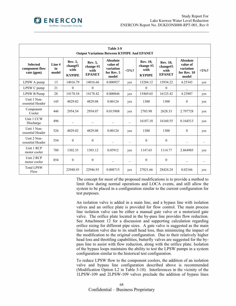
Study Report For Lake Keowee Water Level Reduction ENERCON Report No. DUKEONS008-RPT-001, Rev 0
68 Confidential – Business Proprietary
Table 3-9 Output Variations Between KYPIPE And EPANET
Selected component flow
rate (gpm)
Line # in
model
Rev. 5, chang#5
with
KYPIPE
Rev. 5, change #5
with EPANET
Absolute value of
variation for Rev. 5
model
<5%?
Rev. 10, change #5
with
KYPIPE
Rev. 10, change#5
with EPANET
Absolute value of
variation for Rev. 10
model
<5%?
LPSW A pump 13 14016.79 14016.66 0.000927 yes 15284.12 15934.22 4.25343 yes
LPSW C pump 21 0 0 _ _ 0 0 _ _
LPSW B Pump 28 14178.54 14178.42 0.000846 yes 15469.65 16125.42 4.23907 yes
Unit 1 Non-essential Header
145 4829.02 4829.08 0.00124 yes 1300 1300 0 yes
Component Cooler
446 2954.54 2954.07 0.015908 yes 2703.98 2628.33 2.797728 yes
Unit 1 CCW Discharge
496 _ _ _ _ 16187.18 16160.55 0.164513 yes
Unit 1 Non-essential Header
526 4829.02 4829.08 0.00124 yes 1300 1300 0 yes
Unit 2 Non-essential Header
554 0 0 _ _ 0 0 _ _
Unit 1 RCP motor cooler
780 1302.35 1303.12 0.05912 yes 1147.65 1114.77 2.864985 yes
Unit 2 RCP motor cooler
854 0 0 _ _ 0 0 _ _
Total LPSW Flow
22948.93 22946.93 0.008715 yes 27821.66 28424.24 0.02166 yes
The concept for most of the proposed modifications is to provide a method to limit flow during normal operations and LOCA events, and still allow the system to be placed in a configuration similar to the current configuration for test purposes.
An isolation valve is added in a main line, and a bypass line with isolation valves and an orifice plate is provided for flow control. The main process line isolation valve can be either a manual gate valve or a motorized gate valve. The orifice plate located in the by-pass line provides flow reduction. See Attachment 12 for a discussion and supporting calculation regarding orifice sizing for different pipe sizes. A gate valve is suggested as the main line isolation valve due to its small head loss, thus minimizing the impact of the modification to the original configuration. Due to their relatively higher head loss and throttling capabilities, butterfly valves are suggested for the by-pass line to assist with flow reduction, along with the orifice plate. Isolation of the bypass loops maintains the ability to test the LPSW pumps in a system configuration similar to the historical test configuration.
To reduce LPSW flow to the component coolers, the addition of an isolation valve and bypass line configuration described above is recommended (Modification Option L2 in Table 3-10). Interferences in the vicinity of the 1LPSW-109 and 2LPSW-109 valves preclude the addition of bypass lines

Study Report For Lake Keowee Water Level Reduction ENERCON Report No. DUKEONS008-RPT-001, Rev 0
69 Confidential – Business Proprietary
around these valves. The component coolers of Unit 1 and Unit 2 share a common 12” header in the turbine building. This common header has sufficient space and clearances to install the isolation valve and bypass line depicted in Figure 3-2. Unit 3 would have a similar configuration upstream of the 3LPSW-109 valve. Isolation of LPSW flow to the component coolers is accomplished by installation of the motorized gate valve depicted in Figure 3-2, but without the bypass line/valves/orifice. This motorized gate valve will be provided with the ability to close upon receipt of an ESF actuation signal. This is option L1 in Table 3-10.
Reducing LPSW flow to RCP motor coolers can be accomplished by adding an isolation valve and bypass line on the 10” RCP header upstream of the LPSW-6 valve as illustrated in Figure 3-3. This is option L4 in Table 3-10. Walk-downs are needed to determine if sufficient clearances exist to install a bypass line around the LPSW-6 valves (option L-3 in Table 3-10).
Reducing LPSW system flow demands by eliminating flow to the non-essential headers can be accomplished procedurally, without any system modifications. Currently, for an ES Unit experiencing a LOCA, the non-essential header is isolated procedurally by closing valve LPSW-139 prior to aligning LPSW to the LPI Coolers. For a non-ES unit and units under LOOP scenario, the non-essential header can also be isolated by closing the LPSW-139 valves (Reference 8.5). Under accident scenarios, the LPI coolers use the majority of LPSW flow, 18,330 gpm out of 30,655 gpm of LPSW flow in data set #3 of 2EOC-17 test (refer to Table 3-5 and Reference 8.8). Since the non-essential header is isolated before the alignment to the LPI coolers, which account for the majority of worst case LPSW flow, the NPSH of LPSW pumps is not a concern before the LPSW-139 valves are closed. It is recommended that LOCA/LOOP response calculations (References 8.46 and 8.47) be revised to take credit for having the LPSW-139 valves closed to reduce LPSW flow. Although there are no “system modifications” associated with this option, it is identified as Modification option L-5 in Table 3-10. The cost of this option includes revisions to calculations, DBD’s, procedures, and the FSAR.
Table 3-10 Proposed Modification Options of LPSW System
Modification Option # Modification Description L1 component cooler flow isolation L2 component cooler flow reduction L3 RCP motor cooler flow isolation L4 RCP motor cooler flow reduction
L5 Isolation of non-essential header flow with operator
action on LPSW-139 valve

Study Report For Lake Keowee Water Level Reduction ENERCON Report No. DUKEONS008-RPT-001, Rev 0
70 Confidential – Business Proprietary
Figure 3-2 Illustration of Unit 1 and Unit 2 component cooler flow modifications
Notes for Figure 3-2:
Option L1 installs a 12” motorized gate valve that receives and ESF actuation signal to close. This option does not include the bypass line.
Option L2 installs a 12” manual gate valve, as well as the bypass line with its isolation valves and orifice plate.

Study Report For Lake Keowee Water Level Reduction ENERCON Report No. DUKEONS008-RPT-001, Rev 0
71 Confidential – Business Proprietary
Figure 3-3 Illustration of RCP motor cooler flow modifications for a typical unit
Evaluation of LPSW System Modification Options
After running the LPSW model with each proposed modification option listed in Table 3-10, the model output results show different (i.e., lower) LPSW pump flow rate reductions than by simply eliminating the various flows as shown in the data set #3 of 2EOC-17. This is due to the cross-connection of the LPSW flow system. Thus, the flow model outputs are used to calculate LPSW pump required NPSH and the corresponding lake level. The model output of flow reduction and the LPSW modification options are listed in Table 3-11.

Study Report For Lake Keowee Water Level Reduction ENERCON Report No. DUKEONS008-RPT-001, Rev 0
72 Confidential – Business Proprietary
Table 3-11
LPSW Modification Options and Corresponding LPSW Flow Reduction
Mod. Option Modification description
Flow rate in data set #3 of
2EOC-17 (gpm)
LPSW flow reduction based on model output
(gpm)
L1 component cooler flow isolation 2625 1646
L2 component cooler flow reduction - 205
L3 Unit 1 RCP motor cooler flow isolation 1100 536
L4 Unit 1 RCP motor cooler flow reduction - 205
L5 Isolation of non-LOCA unit (Unit 1) non-essential header by closing 1LPSW-139 with operator action 1300 536
Combination of the various LPSW modification options will reduce different LPSW flow rates by different amounts. Table 3-12 lists the different combinations, and provides the resulting LPSW flow reduction and minimum lake level that can be achieved. For example, if option 8 is used (a combination of option L2 and L3), then the required lake level with “A” HPSW pump running at 6000 gpm will be 790.503 feet.

Study Report For Lake Keowee Water Level Reduction ENERCON Report No. DUKEONS008-RPT-001, Rev 0
73 Confidential – Business Proprietary
Table 3-12 Combination of Modification Options and Impact to Lake Level Requirements(1)
Option
Combination of modification options
LPSW flow reduction based on
model (gpm)
lake level with A HPSW pump
running at 6000 gpm (ft)
lake level with A HPSW
pump running at 5400 gpm
(ft)
lake level without
HPSW pump running (ft)
calculation sheet in new attachment
L1 L2 L3 L4 L5
1 x 205 791.976 791.431 786.937 M1 / M2 / M3
2 x 205
3 x x 410 791.389 790.84 786.313 M4 / M5 / M6
4 x 536 791.043 790.492 785.944 M7 / M8 / M9
5 x 536
6 x x 741
790.503 789.947 785.365 M10 / M11/ M12 7 x x 741
8 x x 741
9 x x x 946 790 789.439 784.823 M13 / M14 / M15
10
x
x 1072 789.704 789.141 784.503 M16 / M17 / M18
11 x x x 1277 789.244 788.676 784.004 M19 / M20 / M21
12 x 1646 788.494 787.918 783.181 M22 / M23 / M24
13 x
x
1851 788.113 787.532 782.758 M25 / M26 / M27
14 x x 2182 787.557 786.968 782.134 M28 / M29 / M30
15 x x 2182
16 x x x 2387 787.243 786.649 781.777 M31 / M32 / M33
17 x x x 2718 786.789 786.187 781.253 M34 / M35 / M36
(1) The lake levels presented in Table 3-12 are the minimum lake levels necessary to assure adequate NPSH for the LPSW and HPSW pumps, when supplied by ECCW siphon flow. Preliminary calculations conclude the available NPSH may not be sufficient to preclude pump cavitation at lake levels below these values.

Study Report For Lake Keowee Water Level Reduction ENERCON Report No. DUKEONS008-RPT-001, Rev 0
74 Confidential – Business Proprietary
The summation of flow reductions that may be achieved for each modification has been checked by comparison to the LPSW modification model using EPANET. The results of this comparison are listed in Table 3-13. The EPANET flow model results are slightly higher than the summation of flow reduction from each individual modification. To be conservative, the smaller value of summing individual flow reductions are used for the lake level calculations shown in Table 3-12. Calculation sheets are provided in Attachment 12.
Table 3-13 Comparison of Flow Reduction Between Summation of Flow Reduction From
Each Modification Option and the LPSW Modification Model Output by EPANET
Option Summation of flow reduction
by each mod. option (gpm) EPANET result of flow
reduction (gpm)
3 410 450
6 741 805
7 741 794
8 741 787
9 946 1038
10 1072 1129
11 1277 1384
13 1851 1908
14 2182 2260
15 2182 2276
16 2387 2524
17 2718 2892
Pump Over-Speed Effect on NPSH and Lake Level Calculation
The Keowee digital governor analysis results in a maximum over-frequency excursion of 5% during initial start and loading of the Keowee emergency buses (PIP 00-3229). The frequency excursion should last no longer than 30 seconds after power is restored to the emergency buses. The frequency excursion impact on NPSH and required lake level is evaluated in Attachment 12, using data set #3 in outage 2EOC-17 dated in December 1999 as the base Case 0.
For the maximum frequency excursion of 5%, the final lake level requirement is 796.10 feet. This is below the tested lake level of 796.32 feet. For the long-term variations in frequency of ± 3%, the minimum required lake level is also below the tested lake level. Therefore, frequency excursions and normal fluctuations do not affect LPSW pump operation.

Study Report For Lake Keowee Water Level Reduction ENERCON Report No. DUKEONS008-RPT-001, Rev 0
75 Confidential – Business Proprietary
3.1.8 Activity #8: Evaluate Modifications to Limit Flow to HPSW Loads (Part 1, Option 1b)
Task Summary:
For each HPSW load, determine the current flow rate and the minimum required flow rate for a LOOP/LOCA on one unit and a LOOP on the other two units. With all HPSW loads reduced to their minimum required flow rate, determine the reduction in required net positive suction head for the HPSW pumps and the corresponding reduction to the minimum required level in Lake Keowee. Additionally, provide proposed methods to limit flow to the HPSW loads.
Evaluation
HPSW system is used primarily to provide fire protection services throughout the Oconee station. HPSW also supplies seal water and cooling water to the following loads:
Backup to LPSW for High Pressure Injection (HPI) Pump Motor Coolers
Backup to CCW for Turbine Driven Emergency Feedwater (EFW) Pump Oil Coolers
Backup to LPSW for Siphon Seal Water (SSW) System
Primary Instrument Air Compressor
Breathing Air Compressors
NPSH and required lake level calculation
In this study, the available net positive suction head (NPSHA) is calculated based on the test data set # 6 of PT/2/A/0251/023 (LPSW system flow test) performed on 12/02/99 (2EOC-17). See Attachment 13 for detailed calculations. The required net positive suction head (NPSHR) is obtained from the HPSW pump curve. The difference between NPSHA and NPSHR gives NPSHmargin which is then subtracted from the current lake level (LLC) to obtain the minimum required lake level (LLR).
Bounding case
According to calculation OSC-6176, the bounding case for HPSW pump NPSH is assumed to be a LOOP with one unit in LPI decay heat removal mode and CCW in siphon flow mode with CCW pumps off. This calculation proves that the minimum required lake level is 791.03 feet, assuming an HPSW flow of 6,000 gpm.
UFSAR section 9.5.1.5.2 states that the greatest demand for fire protection water is 4,071 gpm, which includes 1000 gpm for fire hose streams, 500 gpm for non-fire related loads and 2,571 gpm for Unit 3 Turbine Building Mezzanine floor sprinkler system. An additional demand of 1001 gpm is required for the minimum flow path during fire mitigation (RP/0/B/1000/029). Therefore, the largest expected HPSW flow demand adds up to 5,072 gpm. For the purposes of this study, a conservative value of

Study Report For Lake Keowee Water Level Reduction ENERCON Report No. DUKEONS008-RPT-001, Rev 0
76 Confidential – Business Proprietary
5,400 gpm is assumed for minimum HPSW flow. If the flow demand is reduced to 5,400 gpm, the minimum required Keowee Lake level can be lowered from 791.03 feet to 786.63 feet. Table 3-14 shows calculation results for “A” HPSW pump with flows ranging from 6,000 gpm down to 4,071 gpm.
Table 3-14
HPSW Pump NPSH
HPSW flow rate (gpm)
NPSHA
(ft)
NPSHR
(ft) Required lake level
(ft)
6,000 25.29 20 791.03
5,400 27.58 17 786.63
4,500 28.62 15 782.70
4,071 29.46 14 780.86
HPSW System Modification
In order to limit the HPSW pump discharge flow to 5,400 gpm, the following modification is suggested:
Currently, isolation valves HPSW-3 (at the discharge of HPSW Pump A) and HPSW-6 (at the discharge of HPSW Pump B) are located inside the fire-proof concrete block that houses the fire pumps. The proposed modification will relocate the above isolation valves downstream on their respective 14” line coming out of the concrete fire block, and add a 12” bypass loop around each isolation valve. The bypass loop consists of an 8” orifice plate and a manually operated butterfly valve on either side of the orifice plate. This configuration provides a means to reduce flow during normal operation, with valves HPSW-3 and HPSW-6 closed. With the bypass loops isolated, it maintains the ability to test the HPSW pumps in a configuration similar to the historical test configuration. Attachment 14 shows the modified HPSW flow diagram. There is insufficient space to install these bypass loops in the area where valves HPSW-3 and HPSW-6 are currently located.
Using EPANET software, the hydraulic model of the HPSW System, OSC-5539 Rev. 9, was revised to evaluate the proposed configuration. The results indicate that by closing valves HPSW-3 and HPSW-6 and opening the bypass loops, pump discharge flow can be reduced to approximately 5,400 gpm. Attachment 11 provides the pipe line list and brief description of the proposed modification.

Study Report For Lake Keowee Water Level Reduction ENERCON Report No. DUKEONS008-RPT-001, Rev 0
77 Confidential – Business Proprietary
3.1.9 Modifications to Chiller Condenser Service Water Pump Supply Line
3.1.9.1 Activity #9A: Evaluate Modifications to Allow LPSW to Supply Chiller Condenser Service Water Pumps (Part 1, Option 1b)
Task Summary:
Develop a design concept to supply the Chiller Condenser Service Water (CCSW) pumps with water from the LPSW essential header while allowing isolation of the loads fed from the Unit 1 non-essential LPSW header.
Evaluation
The CCSW system supports operation of the Control Room Ventilation Chilled Water system. By using the LPSW essential header as the normal water supply, evaluate if ample water pressure would be available to meet the CCSW pump NPSH requirements. This would remove the restriction that declares the Control Room Ventilation Chilled Water system inoperable at Lake Keowee levels less than 790 feet (See Table 1-1, SLC 16.9.7.g).
Two options were identified as possible solutions for this activity:
First Option
Conceptual Design Description
The first option installs a new 8” branch line off of the LPSW “A” Essential Header to supply water to the inlet piping of the CCSW Pumps. This new branch line would include a remote/manually-operated isolation valve, and would be approximately 180 feet in length from a point just upstream of valve 2LPSW-139 to the CCSW Pumps O-400B (Reference 8.10 and O-1400A (Reference 8.13). An 8 inch line is assumed based on the size of the supply piping when the CCSW system was originally fed from LPSW. The supply to CCSW was changed from LPSW non-essential header to CCW by NSM ON-53001 in order to maintain cooling water supply to the chillers following a LOCA/LOOP on Unit-2. The new 8” branch line would tie into LPSW just upstream of the Non-essential header. This line would be seismically qualified from the tap off of the Essential Header to the outlet of the isolation valve. Additionally, a manual isolation valve, also seismically qualified, would be installed upstream of the remote/manually-operated isolation valve to allow for maintenance. This maintains the seismically rated pressure boundary of the LPSW Essential Headers.
As part of this installation, new pipe supports would be installed as well as modifications to existing pipe supports along the line routing.
Finally, safety related power would be provided to the valve operator, and control wiring from the valve to a pushbutton in the Control Room would be installed to allow operator control.
Functional Design Assessment
This option provides a simple design which accomplishes the activity objective. Only a minimal amount of seismically qualified piping and components are necessary.

Study Report For Lake Keowee Water Level Reduction ENERCON Report No. DUKEONS008-RPT-001, Rev 0
78 Confidential – Business Proprietary
Second Option
Conceptual Design Description
The second option would use the existing Unit 2 LPSW Non-Essential Header to supply the CCSW pumps. Since this header is not currently seismically qualified, piping analysis and modifications would be necessary to qualify the piping pressure boundary for a seismic event. Additionally, seismically qualified, remote/manually operated isolation valves would be installed on each normally open branch connection (approximately 9, total) off of the header to allow isolation of each non-essential load during a LOOP event. The existing, normally closed branch connection, which formerly supplied the CCSW pumps, would be the new supply line to the CCSW Pumps.
As part of this installation, new pipe supports would be installed as well as modifications to existing pipe supports along the line routing.
Finally, safety related power would be provided to all new valve operators, and control wiring from the valves to pushbuttons in the Control Room would be installed to allow operator control.
Functional Design Assessment
This option provides a more complex solution than the first option but does not require any new pipe routing. If insufficient space is available in this area for the new supply line described in the first option, this option could satisfy the design objective while maintaining the seismically rated pressure boundary of the LPSW Essential Headers and providing the controls necessary to isolate the non-essential loads during a LOOP event. This option would require significant and costly seismic analysis and modifications to implement. Approximately 9, new, seismically qualified, remote/manually operated isolation valves would be have to be installed as opposed to the single new valve required for first option.
Conclusion
The area between branch off the essential header to the non-essential header and the chiller strainer inlet was walked down on 10/20/2010 with site personnel. The area is generally free of interferences to allow several possible routes for new piping. Additionally, multiple locations were identified off the essential header and near the CCSW strainer inlet where a tee or branch line could be installed to support the first option. Due to the ease of installation and minimal amount of seismically qualified piping and components required for the first option when compared to the second option, the first option is selected as the preferred method of supplying LPSW to the CCSW pumps. This would eliminate the SLC 16.9.7 lake level requirement to maintain CCSW operability.
Refer to Attachment 11 for an estimate of necessary piping and supports. Attachment 15 provides a suggested routing for the new branch connection and tie-in to the CCSW strainer inlet piping.

Study Report For Lake Keowee Water Level Reduction ENERCON Report No. DUKEONS008-RPT-001, Rev 0
79 Confidential – Business Proprietary
Evaluation of CCSW Tie-in to LPSW System
Although this modification eliminates the lake level requirement within SLC 16.9.7 to maintain CCSW operability, the CCSW tie-in to the LPSW system results in an increase in lake level requirements. Supplying CCSW pumps with LPSW provided directly from the essential LPSW header adds 1,200 gpm flow demand to LPSW. Isolation of the non-essential header reduces LPSW flow demand by 536 gpm. Thus, the total LPSW flow after Chiller tie-in will be 30,655 + 1,200 – 536 = 31,319 gpm. Using the bounding scenario for LPSW system configuration and the methodology for flow reduction cases, the minimum required lake level is estimated to be 794.86 feet with an LPSW flow demand of 31,319 gpm and “A” HPSW pump running at 6000 gpm.
Table 3-15 below shows the estimation of required lake level for CCWS tied in to LPSW, with and without isolation of the non-essential header. When comparing the results in column 2 in Table 3-15 to the data set #3 case results in Table 3-6 with LPSW flow of 30655 gpm, CCSW tie-in raises the required lake level about 4.4, 4.4 and 4.6 feet for “A” HPSW pump running at 6000 gpm, 5400 gpm and 0 gpm, respectively. These increases can be used when considering CCSW tie-in combined with other modification options listed in Table 3-12. Note that the lake levels in Table 3-15 for CCSW tie-in are estimated values. For flow rates higher than the 30,655 gpm LPSW flow plus the 6,000 gpm of “A” HPSW flow, friction losses on the LPSW pump suction side increase and the NPSHA decreases, thus leading to a relatively higher lake level requirement.
Table 3-15
CCSW Tie-in to LPSW Essential Header
Effect on Required Lake Level
Required lake level with Chiller
tie-in to LPSW (ft)
Calculation sheet in
Attachment 12
Required lake level with non-essential headers
isolated and Chiller tie-in to LPSW (ft)
Calculation sheet in
Attachment 12
lake level with A HPSW pump
running at 6000 gpm (ft)
796.97 M-chiller-1 794.86 M-chiller-4
lake level with A HPSW pump
running at 5400 gpm (ft)
796.45 M-chiller-2 794.33 M-chiller-5
lake level without HPSW pump running (ft)
792.17 M-chiller-3 789.97 M-chiller-6

Study Report For Lake Keowee Water Level Reduction ENERCON Report No. DUKEONS008-RPT-001, Rev 0
80 Confidential – Business Proprietary
3.1.9.2 Activity #9B: Evaluate Options to Increase NPSHa to Chiller Condenser Service Water Pumps (Part 1, Option 1b)
One option evaluated was to consider what impact flow reduction modifications to LPSW and HPSW could have on CCSW pump NPSHa. Reducing flows in the LPSW and HPSW systems will result in decreased flow demands of the CCW system. Theoretically, the pressure at the CCSW tie-in point along the CCW crossover header (at valve CCW-460) will increase, as would the NPSHa at the CCSW pump suction. To confirm this, Rev. 5 of LPSW flow model was used to evaluate the change in pressure at this point resulting from the LPSW and HPSW flow reduction modifications for Option 14 (see Table 3-12). The results show a slight increase in pressure, but it is not sufficient to provide adequate NPSHa for the CCSW pumps with a flow rate of 1200 gpm and a lake level at 787 feet. This is consistent with the sensitivity analysis results shown in OSC-2280 which indicate that the effect of having flow to the “A” and “B” Chiller Condensers has an insignificant impact on the lake level requirement.
The second option evaluated was to install a booster pump to increase head pressure at the CCSW pump suction. There are two hydraulic issues impacting CCSW pump operability at lake levels below 790 feet. One issue is adequate NPSHa, and the other is air de-entrainment. SLC 16.9.7.g states that lake level must be maintained above 790 feet to assure CCSW pump operability, due to potential air de-entrainment at lake levels lower than 790 feet in ECCW siphon flow mode. These two issues are explored by the calculations of NPSH available and hydraulic grade line (HGL) at the second high point along the supply line between the CCW crossover header and the CCSW pump suction. The flow capacity of the CCSW pump is set at the maximum flow of 1200 gpm according to the data shown in Section 7.2.6 in OSC-2280.
Based on the calculation of NPSH available for CCSW pump with the flow rate of 1200 gpm at the lake level of 787 feet (Attachment 28, tabs 1 and 2), an additional 8 feet of head is required to ensure NPSH available is at least equal to NPSH required.
Based on the calculation of HGL at the second high point along the supply line of the CCSW pump (Attachment 28, tabs 3 and 4), an additional 22.4 feet of head is required to ensure that the pressure at the second high point is greater than the fluid’s vapor pressure with the flow rate of 1200 gpm and the lake level of 787 feet. Since the required additional head for the second high point pressure concern is more restrictive than the NPSH available concern for CCSW pump, the suction pressure at the CCSW pump is further evaluated as shown in Tab 2 and Tab 4 of Attachment 28. The 22.4 feet of head is conservatively rounded up to 25 feet. Adding 5 more feet of head to

Study Report For Lake Keowee Water Level Reduction ENERCON Report No. DUKEONS008-RPT-001, Rev 0
81 Confidential – Business Proprietary
account for the added pipe, valves, and fittings brings the total developed head required for the new booster pump to 30 feet. This is sufficient to preclude pump cavitation and air de-entrainment in the CCSW system at 1200 gpm and a lake level down to 787 feet msl.
3.1.10 Activity #10: Upgrade to the Keowee Hydro Power Path to Power CCW Pumps (Part of Part 1 Option 1c)
Task Summary
Determine the necessary upgrades to the Keowee Hydro power path to be used as emergency power for the CCW pump motors and CCW pump discharge valve operator motors in the event of a LOCA and loss of offsite power on one unit and loss of offsite power on the other two units
Evaluation
Keowee Hydro Power Delivery Upgrade
From Activity #1 above it was determined that site wide, eight CCW pumps are required to operate to provide the necessary NPSH for the LPSW, HPSW and CCSW pumps assuming a site wide loss of offsite power (LOOP) and a LOCA on one unit. To provide adequate margin and maintenance flexibility and to meet single failure criteria, all twelve pumps will be able to be powered from the existing Keowee Hydro Unit via new cables and transformer.
The proposed electrical configuration (see Figure 3-4) would allow for automatic transfer to Keowee Hydro for any selected CCW pump. It is designed for emergency power to be provided by a single Keowee Hydro generator, which is the same as the present configuration for other safety related loads. This requires new breakers at Keowee tied to a new underground cable feeding a transformer at Oconee to power the CCW pump motors. The CCW pump motors are rated at 1750 horse power each which is equivalent to approximately 1535 kW. This primary load and additional loads have been estimated in Table 3-16 below:
Table 3-16 Electrical Load Capacity for CCW Pump Keowee Hydro Feeder (Part 1 Option 1c)
Load kw Qty (min
load) Total kW (min load)
Qty (max load)
Total kW (max load)
CCW pump 1535 1 1535 8 12280
Discharge Valves 7.5 1 7.5 8 60
Total 1543 12340
Since the primary additional load being supplied by Keowee Hydro is the CCW pumps, routing the new Keowee feeder directly to the CCW pumps enables the direct wiring of CCW pumps. A new switchgear building will be located near the CCW pumps and existing trench. This location allows the existing CCW pump motor feeders to be pulled back and fed into new transfer switches so that the pumps may be fed either by the original plant

Study Report For Lake Keowee Water Level Reduction ENERCON Report No. DUKEONS008-RPT-001, Rev 0
82 Confidential – Business Proprietary
feeder, for normal operation, or the new Keowee Hydro feeder, during a LOCA or LOOP.
Two new breakers will be added at the Keowee Powerhouse, one for each of the Keowee Hydro generators. These breakers will tie to the new feeder. The new feeder from Keowee will be routed in a new trench to the new switchgear buildings. New feeders will be routed to the CCW pumps through a reworked section of the original CCW pump trench, from the new switchgear buildings to the CCW pumps. Sump pumps will be installed along the new trench, where required, to ensure proper drainage of the trench.
An additional feeder will be added to the existing CCW trench, routed to the new switchgear buildings, which will provide a power source for the CCW pump discharge valves.
Existing discharge valve power wiring will be abandoned. New power feeders will be run from the new switchgear building for the discharge valves, which will power the valves from grid power during normal operation, and auto switch to Keowee power during a LOCA or LOOP.
Independent CCW pump controls will be provided for the new safety related equipment fed by the new Keowee feeder. Existing CCW pump controls will need to be modified. Based on the findings of Design Study ONDS 331, load shed contacts must be bypassed to allow CCW pump restart, and all non-safety related electrical and mechanical interfaces must be isolated to meet separation criteria. Sequencing of CCW pump restart must be designed to meet the needs at the current lake level.

Study Report For Lake Keowee Water Level Reduction ENERCON Report No. DUKEONS008-RPT-001, Rev 0
83 Confidential – Business Proprietary
Figure 3-2, CCW Powered by Keowee
Figure 3-4, CCW Powered by Keowee Hydro

Study Report For Lake Keowee Water Level Reduction ENERCON Report No. DUKEONS008-RPT-001, Rev 0
84 Confidential – Business Proprietary
Main Electrical Switchgear and Transformer Buildings
The main electrical switchgear equipment is required to be housed near the existing CCW Intake Structure located north of the Intake Basin. Three equipment rooms are planned to be sited approximately 500 feet north of this Intake Structure (see Attachment 6). The rooms will be situated adjacent to one another within a common structure. A fire-rated separation wall of approximately 1 ft thick concrete will be located between the equipment spaces. The structure will have a maximum footprint of 20 ft x 60 ft with a low-slope roof of approximately 12 ft interior clearance. The exterior walls are 2 ft thick concrete shear walls and the roof is approximately 1 ft thick concrete flat slab. Structural requirements would be similar to that required for the diesel generator building in the diesel generator option (i.e., Activity #2). An opening is provided in an exterior wall for installation and maintenance access. The opening is sealed with linear concrete blocks spanning the width of the opening. A single man-door is provided for each room, which opens directly to the exterior. The man-door is protected by a concrete alcove. Rooftop ventilation equipment will be installed to prevent excessive heat build-up in each room. Any intake louvers on exterior walls will be protected by concrete walls. The fire protection system will be self-contained and not harmful to the electrical components. The roof will be waterproofed with an insulated single-ply membrane system. Rainwater drainage would likely be collected by an exterior gutter system along one wall of the building.
A new transformer building is positioned in a concrete enclosure adjacent to the north end of the new switchgear building. A single equipment room, housing one transformer, will have a maximum footprint of 30 ft x 40 ft with a low-slope roof of approximately 12 ft to 14 ft interior clearance. A fire-rated separation wall will be located between the transformer module and the switchgear building. The structure will include an oil containment pad around the transformer, perimeter and intermediate concrete walls, a concrete roof, and a concrete floor slab like that of the switchgear building. An opening is provided in an exterior wall for installation and maintenance access. The opening is sealed with linear concrete blocks spanning the width of the opening. Two single man-doors are provided, which open directly to the exterior. The man-doors are each protected by a concrete alcove. Rooftop ventilation equipment will be installed to prevent excessive heat build-up in each room. Any intake louvers on exterior walls will be protected by concrete walls. The fire protection system will be self-contained and not harmful to the electrical components. The roof will be low-slope and waterproofed with an insulated single-ply membrane system. Rainwater drainage would likely be collected by an exterior gutter system along one wall of the building.
Keowee Powerhouse Modifications and New Trench
To provide power from the Keowee Hydro generators new breakers are required at the Keowee Powerhouse. The existing Keowee Powerhouse breaker vault does not have sufficient space to add any new breakers. As a result a new breaker vault will need to be added to the north side of the

Study Report For Lake Keowee Water Level Reduction ENERCON Report No. DUKEONS008-RPT-001, Rev 0
85 Confidential – Business Proprietary
powerhouse in the vicinity of an existing concrete pad. This breaker vault will have a footprint of approximately 20 ft x 20 ft with 20 ft of interior clearance. The walls will be 2 ft thick concrete with a 1 ft thick flat slab roof to provide tornado missile protection similar to the existing vault. Structural requirements would be similar to that required for the diesel generator building in the diesel generator option (i.e., Activity #2).
The powerhouse is a restricted area and therefore the access into the new breaker vault will need to be from the powerhouse. The powerhouse in this area has concrete walls and steel bracing that will need to be removed and reconfigured to allow personnel and equipment access. New core bores will need to be provided through the exterior concrete wall directly below the main level adjacent to the existing core bores servicing the main Keowee trench to the plant. The soil in this area contains significant rock that will need to be removed to allow installation of conduits to service the new breaker vault and subsequently the new trench to power the CCW pumps.
To provide a direct feed from the Keowee generators a new trench will be required from the new breaker vault to the new transformer building north of the CCW pumps. The proposed routing is shown in Attachment 16 and the trench will be similar in design to the existing trench as shown on drawing O-396 T1-001. The new trench coming out of the powerhouse may go through rock for the first 1000 feet. After this initial portion the trench will go over rolling terrain that will require earth work and grading and drainage modifications to minimize the vertical oscillation of the trench. The trench will pass between the two switchyards on the east side of the plant. In this area the trench will need to be above ground to not disturb undergrounds and the overhead transmission line tower foundations. With the duct bank above ground a unique design will need to be coordinated with security to prevent hiding places and walls for potential adversaries. The ground water table over most of the trench’s length is assumed to be within the profile of the trench. To minimize the buoyancy pressures and lateral pressures on the trench due to the ground water, French drains or a similar type of drain will be required along both sides of the trench. To provide internal relief should water get inside the trench, sump pumps will be installed in catch basins at intervals of approximately every 100 ft (or closer as dictated by the terrain). The trench will require a special design where it goes under or over the existing Keowee trench and where it crosses at least three roadways. Two FERC boundaries will be crossed by the trench with one at the Keowee Powerhouse and another at the CCW pumps. Special permits will be required to build the trench in this area. This option depends on the permits being approved.
3.1.11 Activity #11: Provide Detailed Evaluation of Feasibility of Alternatives (For Part 1 Options 1a, 1b & 1c)
Task Summary:
Evaluate the feasibility of the three options considered to allow operation of ONS at a Lake Keowee level as low as 787 feet and thus eliminate the dependence on the ECCW siphon for providing the necessary NPSH for the

Study Report For Lake Keowee Water Level Reduction ENERCON Report No. DUKEONS008-RPT-001, Rev 0
86 Confidential – Business Proprietary
LPSW, HPSW and CCSW pumps following a LOCA concurrent with a loss of power for one unit and loss of offsite power on the other two units.
Evaluation
Part 1 Option 1a
For Part 1 Option 1a, a minimum of eight CCW pumps are required to operate in order to meet the NPSH requirements for LPSW, HPSW and CCSW during a loss of offsite power condition. In order to meet single failure criteria and to ensure sufficient operational flexibility, all twelve CCW pumps, their respective discharge valves and valve operators, and their power supply, instrumentation and controls must be upgraded to QA-1 status. Upgrade of the pumps, valves, and valve operators can be achieved through the commercial grade dedication process. To power CCW pump motors and the discharge valve motor operators, safety related diesel generators must be provided since the safety related power supply from Keowee Hydro via the underground line from transformer CT-4 is insufficient to power this additional load.
The main issue regarding feasibility for Part 1 Option 1a option is the location of a proposed building in which to house the safety-related diesel generators. Site #4 (see Attachment 3 for location) appears to be the most favorable location.
Implementation of Part 1 Option 1a would require several changes/additions to the Oconee Technical Specifications. A new LCO would be needed to specify operability requirements for CCW pumps and discharge valves. A new LCO would also be needed to define operability requirements for the new safety-related diesel generators required to provide power to the CCW pumps and discharge valves and to address diesel generator auxiliary systems. Revisions would be required to LCO’s 3.7.8, 3.8.1, 3.8.2, 3.8.3, 3.8.4, 3.8.8, and 3.8.9, Programs and Manuals Section 5.4, and to SLC 16.9.7.
Construction and implementation can be managed in such a way as to minimize impact to plant operations. However, final tie-ins for safety related power and controls for a unit’s CCW pumps, motors, and valves will require that unit to be in Mode 5 or 6. The total cost estimate for Part 1 Option 1a is provided in Section 7 and Attachment 23.
Permitting
Because the proposed diesel generators are a source of air pollutant, either an air permit or an explicit exemption from the appropriate environmental agency - Federal Environmental Protection Agency (EPA) or State/County environmental agency must be obtained. Based on preliminary information regarding the proposed diesel generators for Duke ONS, applicable South Carolina environmental regulations were reviewed, and informal, off-the-record discussions with air permitting personnel from the South Carolina Department of Health and Environmental Control (SCDHEC), Bureau of Air Quality (BAQ), were conducted to provide a high level of confidence in the scope and budgetary estimates.

Study Report For Lake Keowee Water Level Reduction ENERCON Report No. DUKEONS008-RPT-001, Rev 0
87 Confidential – Business Proprietary
The proposed 6.75 MW generators will require a construction permit for the construction/installation of the units, under South Carolina Regulation 61-62. The specific type of construction permit application would have to be determined at the time of project initiation, and upon completion of an emissions inventory to determine the amount and type of emitted pollutants. The construction permit application would have to be reviewed and signed by a Professional Engineer registered to practice in South Carolina. Once approved, the construction permit may become invalid if construction is not commenced within 18 months after receipt of approval. There is no application fee associated with the construction permit, unless an expedited construction permit is requested. In that case, application fees can range from $3,000 to $25,000 depending upon the type of construction permit application. The cost for the preparation of the construction permit application would be between $10,000 and $15,000. If Prevention of Significant Deterioration is required (PSD), additional effort and cost would be needed. This would include air quality analysis, additional impacts analysis, and public involvement. The cost for PSD would be approximately $50,000.
Once the diesel generators are installed, an air operating permit is required for the operation of the units. An evaluation (considering the specific diesel generator chosen) is needed to address the applicability of and ensure compliance with Title V of the Clean Air Act. This involves an assessment of the current status of the site’s air permit, and what the impact of adding the diesel generators will be. If the owner/operator or professional engineer in charge certifies construction as provided in the air construction permit, the permittee may operate the source in compliance with terms and conditions of the construction permit until the operating permit is issued by SCDHEC. Written notification to the SCDHEC of the actual date of initial startup must be submitted within 15 days after such date.
Site development for the installation of the proposed diesel generators and associated equipment buildings would require an SCDHEC Notice of Intent (NOI) for Stormwater Discharges from Large and Small Construction Activities- National Pollutant Discharge Elimination System (NPDES) General Permit SCR10000. As authorized by the Clean Water Act and regulated by the U.S. Environmental Protection Agency (EPA), the NPDES permit program controls water pollution by regulating point sources that discharge pollutants into Waters of the U.S. The EPA authorizes states to administer their own NPDES permit program and South Carolina is an authorized state. The NOI includes multiple tasks to complete the permit. The estimate of work to complete the NOI is based on the following:
Prepare/complete the construction Stormwater Pollution Prevention Plan (SWPPP) and stormwater management calculations, design and drafting of SWPPP best management practices (BMPs) as required by the NOI.
Infiltration testing will likely be required and costs for tests have not been included in this study. This work should be coordinated with

Study Report For Lake Keowee Water Level Reduction ENERCON Report No. DUKEONS008-RPT-001, Rev 0
88 Confidential – Business Proprietary
the geotechnical firm that would provide the soil borings and geotechnical investigation.
Temporary permits will be required for highway access to support construction activities. No permanent highway access is required.
Calculations required to prepare the erosion, sedimentation and control (E&S) plan as part of the NOI will be performed. BMPs will be used and every effort will be made to locate and use E&S BMPs that can be turned into permanent stormwater management BMPs. This will save construction dollars and limit earth disturbance.
Complete E&S calculations, design and draft of E&S devices, and prepare Maintenance Procedures for E&S.
Review 100 year flood plain and place on drawings. It is assumed that an FEMA map is available denoting 100 year floodplain.
Pre and post stormwater runoff calculations will be performed using the method of choice as designated by SCDHEC.
Permanent stormwater management plans will also be prepared.
ONS comments will be incorporated into the Final E&S Plan.
Drainage basin calculations will be based on a single drainage basin of 5 acres.
Scaled Maps of existing site and surrounding areas with two foot contours, boundaries, and improvements will be provided by Duke Energy as necessary.
The collection of survey data is not part of this study.
Payment of any applicable fees required by the NOI as part of this scope of work is not included in the cost estimates.
Identify and map Waters of the U.S. (e.g., wetlands, streams, etc.). Costs for identification of Waters of the U.S. are covered in the Section 404 Delineation Task which is discussed in a separate task item below.
Two infiltrations per acre will likely be needed (propose 30 tests at the 15 acre site). Soil borings are not included in the cost estimate; however, oversight for geotechnical firm that is providing the soil borings and geotech investigation should be coordinated.
As mentioned above, a delineation of Waters of the U.S. (i.e. wetlands, streams, ponds, etc.) will be required to complete the NOI. The delineation will identify and document the presence of Waters of the U.S. within the project area and include a formal delineation of these resources as specified in the US Army Corps of Engineers (Corps) Wetlands Delineation Manual and the Interim Regional Supplements to the Corps Manual. Following on-site investigations, a formal Section 404 delineation report would be prepared for submittal to the Corps. This report will contain materials required by the

Study Report For Lake Keowee Water Level Reduction ENERCON Report No. DUKEONS008-RPT-001, Rev 0
89 Confidential – Business Proprietary
Corp’s Savannah District Regulatory Office for processing the delineation. The Corps allows consultants to prepare Section 404 delineations, but delineations are considered “preliminary” until they are approved by the Corps. If approved, the Corps will issue documentation of their approval via a Jurisdictional Determination (JD) letter.
The study does not include preparation of a Section 404 permit application (if in fact a permit is required). The findings presented in the delineation will document the presence or absence of Section 404 issues within the project area; this is a critical first step in the permitting process. If such resources are present, the delineation will provide details which will aid in (1) planning in support of avoidance and minimization efforts and (2) estimation and quantification of unavoidable project impacts. In addition, Section 404 wetland mitigation of impacts is not included in the cost estimate.
The addition of the above ground storage tanks (ASTs) for fueling the proposed diesel generators will prompt the requirement to update the facilities’ current operations Spill Prevention, Control and Countermeasure Plan (SPCC) and the operational SWPPP. It is assumed that the ONS Facility currently has an operational SPCC and SWPPP plan in place.
The update to the SPCC plan will require the following:
Site Inspection - conduct a site inspection after the completion of the proposed diesel generator building at the ONS facility by a Professional Engineer and/or their agent. ONS will provide access to the site, the current SPCC plan and any associated records. The inspection will be conducted to review the new diesel generator building and confirm any other potential changes since the development of the previous SPCC plan. This inspection is done to review any changes that may materially affect the existing SPCC Plan as required by SPCC regulation.
Prepare the revised Draft SPCC Plan and submit to ONS for review.
ONS Comments will be incorporated into the Final SPCC Plan. If the Facility is in compliance with 40 CFR 112, certification by a Professional Engineer will be provided.
The current operational SWPPP for the ONS facility based on the proposed diesel generator building will need to be revised. Information such as the current SWPPP and related information will be required to complete the update and assumes information will be obtained about the facility from onsite personnel. A separate site visit will not be required since a site visit is already anticipated for the SPCC update.
Assumptions for the SWPPP and SPCCC update tasks include:
SPCC regulation requirements such as AST Integrity Testing Program are not included in the cost estimate. Integrity testing of the new above ground storage tank(s) will be completed by the AST installation contractor. Integrity test will be needed to complete the SPCC Plan.

Study Report For Lake Keowee Water Level Reduction ENERCON Report No. DUKEONS008-RPT-001, Rev 0
90 Confidential – Business Proprietary
Preparation of a Facility Response Plan (40 CFR Part 109) is not included in the cost estimate.
Additional security measures include an extension wall from the eastern end of the intake structure to the nearest shoreline of the lake. The extension wall would be approximately 120 feet in length, 50 feet deep and two feet in width. To complete this task, a Corps Nationwide Permit application for Jurisdictional Waters impacts would be required to be submitted to the Corps’ Charleston District office in South Carolina. Appropriate application materials for submittal of a Corps 404 permit addressing impacts to “Waters of the U.S.” from the project construction and a likely compensatory mitigation package as required by the Nationwide Wetland Permit would be prepared by design organization. Site development for the installation of the proposed buoy system to prevent ingress/egress into the area of the intake structures already located in Lake Keowee would likely require a Lake Use Permit established through Duke Energy’s Shoreline Management Plan guidelines.
Assumptions for the Intake Wall Extension task include:
A Pre-Construction Notification (PCN) for a Section 404 Nationwide Permit will be required. An application for a Section 404 Individual Permit is not part of this study.
A Section 10 permit would not be required for this project.
Delineation of the site would be completed during the delineation of Waters of the U.S. task discussed previously.
Coordination with the U.S. Fish and Wildlife Service will be required during the project; however, this study does not include formal Section 7 consultation if listed threatened and endangered species are identified at the proposed site.
Coordination and consultation with the Duke Energy Land Services (DE-LS) group to determine the extent of modifications required to the Lake Use Permit.
Security Modifications
To determine the feasibility and cost of design changes to support operation of ONS with Lake Keowee level at 787 feet above mean sea level (msl), and also to support ONS operation with Lake Keowee level at 777.1 feet above msl, diesel generators are being added. The location and number of the diesel generators being considered by this study will require modifications to the Plant Security System and the current Plant PA boundary will need to be reconfigured. The issues evaluated in this study include (but are not limited to) the reconfiguration/expansion of the plant PA. This study makes the following assumptions:
a. The proposed PA expansion will reconfigure and expand existing segments of the PA boundary referred to hereafter as the Security Isolation Zone.

Study Report For Lake Keowee Water Level Reduction ENERCON Report No. DUKEONS008-RPT-001, Rev 0
91 Confidential – Business Proprietary
b. Additional Intrusion Detection System (IDS) zones will be created utilizing Infrared technology.
c. Existing IDS alarms are wired to multiplexers at various locations in the plant.
d. There are spare alarm inputs available at a multiplexer to accommodate IDS zones added by this modification.
e. As a result of adding IDS zones, additional cameras will be required to provide assessment of the new IDS zones. There are spare video inputs available in the video cabinet to accommodate the new cameras.
f. The IDS and assessment (cameras) systems are provided with a back-up source of power (UPS) in the event of a loss of normal AC power.
g. The plant security area lighting is provided with a UPS in the event of a loss of normal AC power.
h. In light of item g above, the cameras used for alarm assessment are not thermal cameras and are not equipped with Infrared illuminators.
i. A dedicated security ductbank system exists near the plant perimeter whereby cabling is routed from IDS and camera equipment to the plant security computer system.
j. Bullet resistant enclosures (BRE) will be installed along the reconfigured isolation zone.
k. A temporary sally port will be installed in the isolation zone at the Site 4 area.
In accordance with the above mentioned assumptions, the following modifications to the PA boundary and Security Isolation Zone are expected to be made to accommodate the installation of the new diesel generators:
(1) Isolation Zone
The options for modifying the existing PA and nuisance fences that comprises the Security Isolation Zone are shown in Attachment 5. The extended PA fence and diesel generator building are situated such that they are away from highway 183 and not seen from outside of the plant due to the dense woods that surround the area. The extended PA was located such that the dense woods and other natural features would be as unaffected as possible.
(2) Intrusion Detection System
In accordance with NRC Regulatory Guide 5.44, “Perimeter Intrusion Alarm Systems”, the individual alarm segments should generally be limited to a length that allows observation of the entire segment by an individual standing at one end of the segment. This typically means that segments should not exceed 100 meters (328 feet), but shorter segments may be needed to achieve the desired performance. The lengths of the existing PA fence segments and position of the existing IDS equipment appear to comply with the regulatory position; however the proposed new Security Isolation Zone configuration

Study Report For Lake Keowee Water Level Reduction ENERCON Report No. DUKEONS008-RPT-001, Rev 0
92 Confidential – Business Proprietary
will have segments that are greater than 328 feet in length. Therefore, to comply with the Regulatory Position and to account for changes in elevation due to the natural topography of the terrain, multiple IDS zones will be installed in the reconfigured isolation zones. The new IDS zones will utilize Infrared technology in keeping with the existing IDS technology used at ONS.
(3) Cameras
A single fixed camera will be installed for each new or reconfigured Infrared IDS zone to provide assessment of an IDS alarm at the CAS and SAS. The cameras will be powered from an uninterruptible source of AC power. The make and model of the cameras will be consistent with those currently used at ONS. The cameras will be mounted on towers or poles consist with the existing camera design. A NEMA 4X camera termination box containing fiber converters, data modules and local circuit breakers will be mounted at the base of each pole.
(4) High Mast Area Lighting
It is proposed that 100 foot tall lighting poles with four (4) 1000 Watt fixtures each be installed to provide a minimum of 0.2 foot-candles of illumination measured horizontally at ground level in the isolation zones and appropriate exterior areas within the PA. The fixtures will be fed from an uninterruptible source of AC power to ensure continuous illumination for the camera fields of view in low light or nighttime hours in the event of a loss of normal AC power.
(5) Bullet Resistant Enclosures (BRE)
BREs will be installed inside the PA and along the new fence line. This study proposes that two (2) BREs will be installed at Site 4. Each BRE will be provided with 208-120Vac utility power from a 208-120Vac distribution panel powered from a 480-208/120Vac, 10kVA transformer located at the base of each BRE. The BREs will be equipped with internal lighting and receptacles, external glare lighting and A/C.
(6) Temporary Sally Port
A temporary sally port may be installed in the isolation zone at the Site 4 area if the access road connecting to highway 183 is necessary. An electrically operated anti-ram vehicle barrier (i.e. wedge/bollard/drop arm barrier) with a K12/L3 rating in accordance with Department of State Standard SD-STD-02.01, Rev. A. “Test Method for Vehicle Crash Testing Of Perimeter Barriers and Gates” will be installed and operated from a BRE strategically located near the sally port.
(7) Ductbanks/Embedded Conduit
Additional ductbanks/embedded conduits will be installed from the existing ductbank/raceway system to provide a raceway path to the new and relocated lighting, IDS, and camera equipment. The ductbanks will include 6-4” diameter PVC conduits for 480Vac power to the yard area lighting, 480Vac power to the BRE transformers, 120Vac camera and IDS power, and fiber

Study Report For Lake Keowee Water Level Reduction ENERCON Report No. DUKEONS008-RPT-001, Rev 0
93 Confidential – Business Proprietary
optic and data cabling. Two inch (2”) diameter rigid steel conduits will be direct buried from the manholes to the BREs, light poles, camera termination cabinets, and the IDS connection boxes.
(8) Cabling
Fiber optic and multi shielded pair signal cables will be routed from the IDS and camera terminal boxes to an alarm multiplexer and the CCTV video system cabinet for the new IDS zones and cameras. 480Vac power cables will be routed from the high mast light poles to a 480Vac, 3Ø power panel for the yard area security lighting. Similarly, 480Vac power cables will be routed from the BREs to a 480Vac, 3Ø power panel. Cables for the 120Vac power to the cameras and Infrared IDS will be routed from the terminal boxes of these components to a UPS backed distribution panel for a source of uninterruptible power to the detection and assessment systems in accordance with 10 CFR 73.55. Circuits feeding the existing IDS and camera components may be utilized to feed the new equipment if there is enough available margin on those circuits. This may eliminate the need to route extended lengths of new cables to source distribution panels.
(9) Grounding
A bare stranded copper conductor will be installed the full length of the new ductbanks and be connected to the existing ductbank/manhole grounding system at both ends. Conduits from the lights, camera and IDS equipment entering the new manholes will be connected in the manholes to the ductbank grounding system via conduit grounding locknuts or bushings. A separate ground loop will be installed at the base of the PA and nuisance fences and running the entire length of the fences. The BREs and fences will be grounded in accordance with the site grounding procedures. This fence ground loop will connect back into the existing plant ground grid at both ends of the fence loop.
(10) Security Computer System
The Security Computer System (SCS) database will be revised to incorporate the new IDS alarm zones as well as the camera video.
(11) CCW Pump Security Requirements
Upgrading of the CCW pumps to QA1 would require additional security protections to be installed at the pump locations. The protections necessary for the pumps would be required to ensure that in the event of an attack at ONS, the CCW pumps would remain in operation. The following security protections would be required at the CCW pump locations:
Installation of a Ballistic Barrier around the CCW Pumps
A ballistic barrier is required to be installed around the perimeter of the CCW pumps to ensure that an adversary is not capable of using a firearm to remove the CCW pumps from operation. The barrier would be designed using wide flange beam (W-sections) posts on 10 ft centers. The beams would be anchored to the pump foundation using baseplates and Hilti Kwik Bolt 3 anchor bolts. Ballistic steel

Study Report For Lake Keowee Water Level Reduction ENERCON Report No. DUKEONS008-RPT-001, Rev 0
94 Confidential – Business Proprietary
plates, minimum 8 ft tall, would then be required to be attached to the wide flange sections encircling the pumps and preventing them from being damaged by an adversary. Due to the maintenance requirements on the pumps the ballistic steel barrier would be required to be bolted together. Therefore, bolt holes would be required to be drilled through the ballistic plates and the flanges of the W sections to allow the plates to be bolted to the beams.
Buoy System
The CCW pumps at ONS are located in a cove along the shore of Lake Keowee. Therefore, the potential to remove the pumps from service using a water craft is possible unless a double layer buoy system is installed at the cove entrance. To ensure that a water craft is not capable of reaching the pumps it would be necessary to install a double layer buoy system at a distance greater than the minimum safe standoff distance for a design basis explosion. The double buoy system would provide a barrier that a water craft is not capable of circumventing ensuring that it remains a safe distance from the pumps.
Submerged Security Wall
To allow for security fencing and intrusion detection to be installed, a concrete wall (minimum 2 ft thick) would be required to be installed at the north end of the CCW pump foundations. The wall would provide the footing and installation locations for a new 8 ft tall security fence as well as the new infrared intrusion detection system that would be required at this location. The wall and footing would be a reinforced concrete design with the footing for the wall resting on the lake floor. If the wall cannot be designed with a footing resting on the lake floor it would be necessary to excavate portions of the lake floor to allow the footing to be installed below the lake floor. The total height of the wall would gradually decrease as it approaches the shoreline though the top of the wall must be installed to ensure that it is equal to the height of the pump foundations.
Security PA Fence
Based on the QA1 classification of the CCW pumps, the PA fencing at ONS would need to be extended, such that the PA would enclose the existing pump locations. The new PA fence would be installed such that it tied into the existing PA fence along the east side of the ISFSI and just to the south of the Radwaste Building. Starting at the eastern edge of the ISFSI the fencing would run east across the dike until it intersected with the ballistic shielding installed along the southern edge of the intake structure. Due to the ballistic shielding being installed around the CCW pumps fencing would not be required on the intake structure, though the fencing would need to be installed along the new wall installed to the east of the intake structure. The fencing would run from the southeast corner of the

Study Report For Lake Keowee Water Level Reduction ENERCON Report No. DUKEONS008-RPT-001, Rev 0
95 Confidential – Business Proprietary
intake structure platform across the top of the concrete wall and across the lake shore before tying back into the existing PA fence just to the south of the Radwaste Facility.
Infrared Intrusion Detection System
Based on the requirements of 10CFR73 it is necessary to have an IDS capable of providing an alarm prior to an adversary reaching the PA boundary. Therefore, an infrared intrusion detection system would be required to be installed outside of the PA boundary described in the section above. The installation of the IDS system would create a minimum of three (3) new IDS zones that would be required to be monitored, which would consist of a minimum of 4 new IDS posts with sensors. The three zones would be laid out such that the first zone would be located between the fence tie in to the east of the ISFSI and the southwestern edge of the intake structure platform. Zone two would be across the southern edge of the intake platform just outside of the ballistic barrier, while Zone 3 would be between the southeastern edge of the intake platform and the fence tie in location south of the Radwaste Facility. Two of the IDS posts would be installed using concrete foundations, while the two located at the corners of the intake platform would be required to be installed using a baseplate and anchor bolts.
PA Cameras
A minimum of 4 new PA cameras would be required to be installed along the revised PA boundary to ensure that security is able to assess and detect possible alarms along this boundary. Two of the cameras would be required to be installed such that the cameras were able to view along the fence line located on the south side of the intake structure. The remaining two cameras would be installed at the fence tie in locations to ensure that the new fencing routed along the shoreline is able to be viewed. Depending on the capabilities of the cameras it is possible that additional cameras would be required along the fence to ensure that security is able to maintain adequate surveillance along the revised PA.
These security upgrades around the CCW pumps may impact external flood mitigation, maintenance on the earthen impound structure, intake screen cleaning, pump maintenance, and other items. The impact on these items has not been captured in the cost estimates of this study.
Part 1 Option 1b
For Part 1 Option 1b, modifications are evaluated that reduce flow requirements for LPSW and/or HPSW. A reduction in required flow results in a corresponding reduction in minimum required lake level necessary to ensure adequate NPSHA during CCW siphon flow conditions. For the scenarios addressed within the scope of this study, the target lake level of 787 feet msl can be achieved. CCSW operability limit can be lowered with the installation of a new booster pump. The target lake level of 787 feet is

Study Report For Lake Keowee Water Level Reduction ENERCON Report No. DUKEONS008-RPT-001, Rev 0
96 Confidential – Business Proprietary
achievable for each of the following (see Tables 3-10 thru 3-13 for a detailed summary of the options considered):
LPSW flow requirements reduced to 28,450 gpm (a reduction of 2205 gpm), and the HPSW flow requirements reduced to 5400 gpm. The HPSW load of 5400 gpm is conservatively chosen to account for its use as a backup sources for high pressure injection (HPI) pumps and motor driven emergency feed water (MDEFW)
LPSW flow requirements reduced to 30,450 gpm (a reduction of 205 gpm), and the HPSW flow requirements reduced to zero gpm. If HPSW can be isolated and all the HPSW flow is eliminated, LPSW flow only needs to be reduced by 205 gpm to 30450 gpm.
LPSW flow requirements reduced to 28,050 gpm (a reduction of 2605 gpm) if there is no reduction to HPSW flow requirements.
Implementation of Part 1 Option 1b would require a revision to SLC 16.9.7. Implementation of the proposed LPWS modifications for Units 1 and 2 would require both Units to be in Mode 5 or 6. Implementation of LPSW modifications for Unit 3 would require that Unit 3 be in Mode 5 or 6.
Installation of a booster in the supply line from CCW crossover header to the CCSW pumps will likely require all three units be in an outage, assuming double isolation is required. There is only one isolation valve, CCW-460, between the CCW crossover header and the location proposed for the booster pump. Limited access to this 10” line precludes the use of a freeze plug as a second isolation device. There is an alternate source of water to the CCSW pumps from the LPSW system through valve LPSW-135 if single point isolation is acceptable.
Lake Keowee Water Temperature
The design basis documents and calculations for the LPSW and HPSW Systems identify the maximum Lake Keowee temperature as 90 °F. This temperature was used for determining the available net positive head (NPSHA) for the LPSW and HPSW pumps during accident conditions. The actual NPSHA for the pumps is dependent on the actual water temperature entering the pump suction inlets. The UFSAR for the Oconee Station indicates the Lake Keowee temperature ranges from 45 °F to 85 °F. The 90 °F water temperature is therefore conservative.
The following tabulation in Table 3-17 shows the impact that lake temperatures have on NPSHA. A lake temperature of 90 °F is used as a reference point. The change in NPSHA is noted for temperatures below and above 90 °F.
Table 3-17
Lake Temperature versus NPSHA
Lake Water Temperature (ºF)
Vapor Pressure of Water (ft)
Change in NPSHA (ft) Given 90 °F Water
50 0.41 + 1.21

Study Report For Lake Keowee Water Level Reduction ENERCON Report No. DUKEONS008-RPT-001, Rev 0
97 Confidential – Business Proprietary
Table 3-17
Lake Temperature versus NPSHA
Lake Water Temperature (ºF)
Vapor Pressure of Water (ft)
Change in NPSHA (ft) Given 90 °F Water
60 0.59 + 1.03
70 0.84 + 0.78
80 1.17 + 0.45
90 1.62 0.00
95 1.88 - 0.26
100 2.19 - 0.57
The intake canal to the CCW pumps has a surface skimmer that extends below the surface of Keowee Lake. The function of the skimmer is to prevent surface water from entering the intake canal. Cold water, from the lower depths of the lake, is drawn under the skimmer into the intake canal. Lake Studies conducted during the 1970s and 1980s (Reference 8.62) indicate that the highest surfaces temperatures typically occurred in July and August and range from approximately 80.6 °F to 84.2 °F. The water drawn into the intake canal will experience some surface heating as the water flows towards the CCW Pumps. This surface heating is not expected to have an adverse effect on the water temperature several feet below the intake canal surface.
The current minimum lake level is approximately 794 feet msl. This level is 30 feet above the suction inlet of the CCW pumps. Lowering the Keowee Lake level to 787 feet msl will maintain a vertical water height of approximately 23 feet. The temperature of the water entering the CCW System, (including the downstream LPSW and HPSW Systems) is not expected to change with the lower lake level.
Part 1 Option 1c
For Part 1 Option 1c, like Part 1 Option 1a, a minimum of eight CCW pumps are required to operate in order to meet the NPSH requirements for LPSW, HPSW and CCSW during a loss of offsite power condition. In order to meet single failure criteria and to ensure sufficient operational flexibility, all twelve CCW pumps, their respective discharge valves and valve operators, and their power supply, instrumentation and controls must be upgraded to QA-1 status. Upgrade of the pumps, valves, and valve operators can be achieved through the commercial grade dedication process. To power CCW pump motors and the discharge valve motor operators, an upgrade to the power supply from Keowee Hydro via a new underground line to a new transformer and new switchgear is required to power this additional load.
The main issue regarding feasibility for Part 1 Option 1c option is the location and cost of a new ductbank from the Keowee Hydro Powerhouse to the new CCW pump transformer and switchgear buildings in which to house

Study Report For Lake Keowee Water Level Reduction ENERCON Report No. DUKEONS008-RPT-001, Rev 0
98 Confidential – Business Proprietary
the new safety-related transformer and switchgear. See Attachment 16 for the conceptual routing of the new ductbank.
The level of effort and cost of permitting, site development and security considerations for the CCW pumps, ductbank and transformer and switchgear buildings of Part 1 Option 1c is similar to Part 1 Option 1a discussed above, except that no diesel generator building or above ground fuel oil storage tanks are required for Part 1 Option 1c. The ductbank for Part 1 Option 1c has significant costs associated with its construction and significant design related risks associated with it due to its length and the path that it must follow from the Keowee Hydro Powerhouse to the vicinity of the CCW pumps. Since there is no new diesel generator building associated with Part 1 Option 1c, the security features impact would be restricted to the CCW pumps as discussed in item (11) of the Security Modifications discussion for Part 1 Option 1a above.
Construction and implementation can be managed in such a way as to minimize impact to plant operations. However, final tie-ins for safety related power and controls for a unit’s CCW pumps, motors, and valves will require that unit to be in Mode 5 or 6. The total cost estimate for Part 1 Option 1c is provided in Section 7 and Attachment 23.
The upgrade to the Keowee Hydro Power Path to Power CCW Pumps hinges on numerous permits and calculations that must be approved in order for this option to be feasible. The two most critical areas are at the Keowee Powerhouse and at switchgear building. These two areas are very congested and while there appears to be a path forward, this would need to be evaluated in detail with appropriate agencies relating to permitting to ensure its feasibility.
3.2 Part 2 – Operation at Lake of Level 777.1 feet msl As discussed in Section 2.2 above, there were three distinct activities associated with this part of the study. Each of the three activities is discussed in detail below:
3.2.1 Activity #1: Size and Location of New Diesel Generators to Replace Keowee Hydro
Task Summary:
Evaluate options to allow operation of ONS at Lake Keowee levels as low as 777.1 feet msl by eliminating the reliance on Keowee Hydro to supply emergency loads for ONS Units 1, 2 and 3 during a LOOP event. At Lake Keowee level of 777.1 feet there will not be sufficient inventory to operate the hydro facility to power Oconee emergency loads for the required time period of seven days (see Table 1-1 SLC 16.9.7.j).
Evaluation
This activity evaluated the feasibility of adding diesel generators to replace emergency power currently supplied by Lake Keowee Hydro. The site emergency power requirements were evaluated to differentiate between loads required to meet the licensing basis for the plant (i.e., safety related loads per

Study Report For Lake Keowee Water Level Reduction ENERCON Report No. DUKEONS008-RPT-001, Rev 0
99 Confidential – Business Proprietary
UFSAR Table 8-1 and those loads required to support operation of the Protected Service Water (PSW) system) and those loads needed to cope with a loss of offsite power (i.e., non-safety related loads) per current operating procedures. Current plant operating procedures take advantage of Keowee Hydro capacity over and above UFSAR levels to power additional loads. The power requirements for each of the two load categories were used to specify the number and type of diesels needed. Therefore, two options were considered to address this task.
Part 2 Option 1 - Eliminate Reliance on Keowee Hydro For Emergency Power For Safety Related Loads and PSW System Loads in the Event of a Loss Of Offsite Power
Diesel Generator Sizing
To accomplish this task, a review of electrical requirements to power the safety related plant equipment, PSW System loads, and the auxiliaries for the new diesel generator was used to determine the required diesel generator capacity. UFSAR Table 8-1 tabulates the equipment required to support each unit for LOCA and LOOP conditions. The UFSAR table also differentiates between the equipment automatically connected following each event type and the load that is required to run to mitigate the event. Table 3-18, below summarizes what is presented in UFSAR Table 8-1:
Table 3-18
Electrical Load Requirements
Unit 1 Unit 2 Unit 3
LOCA LOOP LOCA LOP LOCA LOP
Auto Connected (kva) 6993 4380 6274 4489 6803 4489
Required for Event Mitigation (kva)
4784 5084 3902 4378 4255 4731
Table 3-19 below summarizes the load requirements for the site assuming a site wide LOOP and a LOCA on one unit; the values reflect the most limiting unit.
Table 3-19
Bounding Electrical Load Requirements
Auto Connected Required for Event Mitigation
LOCA (kva) 6993 4784
LOOP (kva) 4489 4003
LOOP (kva) 4489 4003
Total (kva) 15,971 12,790
Based on the loading requirements specified in UFSAR Table 8-1 (and summarized above), diesel generators sized to carry a combined minimum load of approximately 16 MVA are required. To provide margin and replicate the capacity of the existing Keowee Unit via Standby Transformer

Study Report For Lake Keowee Water Level Reduction ENERCON Report No. DUKEONS008-RPT-001, Rev 0
100 Confidential – Business Proprietary
CT4 (i.e., 22.4 MVA per UFSAR Table 8-1), the diesel generator total capacity should be sized for 22.4 MVA (17.9MW @0.8 pf).
Additionally, the CCW pump requirements from Part 1 must be added to this total, since the CCW pumps are not currently safety related. Since up to four CCW pumps may be run from any one unit, adequate emergency power must be available to each unit to power all four CCW pumps on each unit. CCW loads are tabulated in Table 3-20 below.
Table 3-20
CCW Pump & Valve Electrical Load
Load kw Qty (max load) Total kW (max load)
CCW pump 1535 4 6140
Discharge Valves 7.5 4 30
Total (kw) 6170
In summary, the total load per unit required is the sum of the present USFAR load per unit, and the CCW load per unit.
Table 3-21
Total Electrical Load (LOOP/LOCA Load Plus CCW Pump & Valve Load)
Load Total kw
USFAR Ch. 8 safety related requirements (17.9MW/3 units) 6000
CCW pumps and valves 6170
Total 12,170
A diesel generator has been selected with a capacity of 13,000 kWe. This satisfies the maximum load, and allows for maximum downturn during less loaded conditions.
Each unit has two diesel generators for full backup. The diesel generators will feed the existing safety related buses for each unit. The electrical configuration is shown in Figure 3-5.
Protected Service Water (PSW) System Electrical Loads
The PSW System is designed as a standby system for use under emergency conditions where plant systems in the Turbine Building are lost. The PSW System will include a dedicated power system. The PSW System provides additional "defense in-depth" protection by serving as a backup to existing safety systems and as such, the system is not required to comply with single failure criteria. The PSW System is provided as an alternate means to achieve and maintain a stable RCS pressure and temperature for one, two, or three units following postulated HELB event scenarios. (Reference 8.63)
The PSW electrical system provides power to portions of the existing High Pressure Injection (HPI) System. The PSW System and those portions of the HPI System powered by the PSW switchgear are referred to as the PSW System. The SSF system is capable of providing secondary side decay heat removal and Reactor Coolant Pump (RCP) seal injection subsequent to a

Study Report For Lake Keowee Water Level Reduction ENERCON Report No. DUKEONS008-RPT-001, Rev 0
101 Confidential – Business Proprietary
HELB event to maintain the affected units in Safe Shutdown (SSD) conditions for up to 72 hours. (Reference 8.63)
The PSW System reduces reliance on systems and components located in the Turbine Building and is capable of mitigating HELBs in that building. The PSW System is redundant to and diverse from the SSF System. (Reference 8.63)
The PSW electrical system is designed to provide power to PSW mechanical and electrical components as well as other system components needed to establish and maintain a Safe Shutdown condition. A separate PSW electrical equipment structure is provided for major PSW electrical equipment. Power is provided from the Keowee Hydroelectric Units via a protected underground path. Alternate power is provided by a transformer connected to a 100 kV overhead transmission line that receives power from the Central Tie Switchyard located approximately 8 miles from the plant. These external power sources provide power to transformers, switchgear, breakers, load centers, and battery chargers located in the PSW electrical equipment structure. (Reference 8.63)
The power system provides backup power to the following: (Reference 8.63)
• 125 VDC Vital I&C Normal Battery Chargers - two (2) per unit.
• One HPI pump per unit (2 HPI pumps available).
• HPI valves needed to align the HPI pumps to the Borated Water Storage Tanks.
• HPI valves and instruments that support RCP seal injection and RCS makeup.
• Pressurizer Heaters (≥400 kW).
• RCS and Reactor Vessel Head high point vent valves.
• Submersible pump.
• Standby Shutdown Facility (SSF).
Because the primary source for the PSW electrical system is from Keowee Hydro, the PSW loads will require diesel generator backup for Part 2, because the Keowee source that is presently relied on will be unavailable. The PSW load has been estimated at a maximum of 10MW. Two of the new diesel generators will be connected to the PSW electrical system for redundant backup. Because the function of the PSW system is to provide additional "defense in-depth" protection by serving as a backup to existing safety systems, the PSW system loads are not concurrent with other safety loads. Because of this, the PSW loads do not need to be added to the loads listed in Table 3-21 and therefore the diesel generators sized to carry the safety related loads of UFSAR Table 8.1 and the CCW pumps and discharge valves are adequate to also supply the PSW system loads.
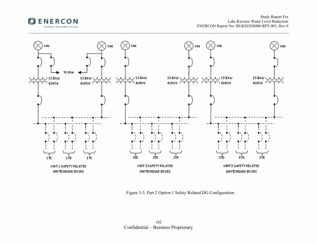
Study Report For Lake Keowee Water Level Reduction ENERCON Report No. DUKEONS008-RPT-001, Rev 0
102 Confidential – Business Proprietary
Figure 3-5, Part 2 Option 1 Safety Related DG Configuration

Study Report For Lake Keowee Water Level Reduction ENERCON Report No. DUKEONS008-RPT-001, Rev 0
103 Confidential – Business Proprietary
Siting of Diesel Generators
Similar to Activity #2 for Part 1 Option 1a, an assessment of available site locations was based on an evaluation of the logistics and physical characteristics of each potential site. Site selection criteria were developed and each site considered was evaluated and ranked using the criteria to determine the optimum site(s).
Eight sites were considered for possible diesel generator locations. Seven of the possible sites were located within the current OCA and one site was adjacent to the OCA across highway 183. Of the seven sites inside the OCA two were located within the existing PA perimeter. Of the eight sites considered, two sites were selected as the primary sites of interest with one site recommended overall. See Attachment 3 for the location of the potential locations considered.
The sites were ranked based on criteria including, but not limited to, the following:
Location
Proximity to terminus of loads
Security
o Vulnerability of duct bank
o Ability to construct new diesel buildings outside of the security perimeter, then move the fence
o Currently located inside security perimeter
Flood requirements
Exhaust fume impacts (including control room habitability)
Soil conditions
Impact on surrounding structures and their operational ability
Impact on plant personnel
Retaining structures required
Size of building
Permitting
Environmental Impact
Civil Site Evaluation Discussion
The following is an assessment of each of the eight sites based on civil considerations:
Site #1
Resides closely to an existing electrical pathway from Keowee Hydro, but is far away from the CCW pumps and the electrical trench is full according to Oconee’s original design criteria
No impact on surrounding structures
Requires a new protected area away from the existing PA

Study Report For Lake Keowee Water Level Reduction ENERCON Report No. DUKEONS008-RPT-001, Rev 0
104 Confidential – Business Proprietary
Removes an existing parking lot
Subject to complete destruction due to “External Flood Event”
Close to FERC Boundary – additional permitting required
Requires hazardous substance permit due to the parking lot being the cap for the site’s previous sewage waste
Site #2
Subject to complete destruction due to “External Flood Event”
Resides close to the CCW pumps and existing duct bank to the current bus
Requires an extension of the existing PA
Not enough area to construct all diesel buildings at this location
Very small site
Impacts the PSW ductbank
Soil is saturated due to seepage from lake above
Site #3
Location is outside of the OCA
Requires a new protected area away from the existing PA
Connecting the site to the plant would be very difficult and costly
No impact on surrounding structures
May conflict with possible new power plant construction
Site #4
Location is near the CCW pumps
Flexibility such that the main construction activities would occur outside of the PA followed by an expansion of the existing PA to incorporate the new building
No impact on existing surrounding structures
Limits expansion capability of existing ISFSI to the north, but would not interfere with current plans to expand the ISFSI to the west
Removes current site dumping ground for soil
Extensive grading and drainage
Above “External Flood Event” water levels
Site #5
Location is inside the existing PA
No security modifications required
Requires the removal of an existing warehouse
Adversely impacts control room habitability
Limits storage area and staging area inside PA

Study Report For Lake Keowee Water Level Reduction ENERCON Report No. DUKEONS008-RPT-001, Rev 0
105 Confidential – Business Proprietary
Costs will probably be associated with contaminated material disposal if any demolition is required
Not enough area to construct all diesel buildings at this location
Site #6
Location is inside the existing PA
Not enough area to construct all diesel buildings at this location if area restricted to inside PA
Above the current analysis for External Flood threat
Area inside of PA is already being looked at for water storage & Appendix R Warehouse.
Requires extensive soil removal
No impact on existing surrounding structures
Adversely impacts control room habitability
Above “External Flood Event” water levels
Site #7
No impact on surrounding structures
Requires a new protected area away from the existing PA
Removes an existing parking lot
Requires removal or relocation of existing CCW pipes
Subject to complete destruction due to “External Flood Event”
Not enough area to construct all diesel buildings at this location
Site #8
No impact on surrounding structures
Sewage Lagoon is decommissioned
Above the current analysis for External Flood threat
44kV Retail Substation is being looked at for a new transformer location (mitigation of External Flood)
Existing Warehouse is abandoned and can be removed
Flexibility such that the main construction activities would occur outside of the PA followed by an expansion of the existing PA to incorporate the new building
Sites #2, #5, #6, and #7 are all too small to construct a building large enough to accommodate all of the diesel generators needed for Part 2 Option 2. Sites #2 and #7 would be very difficult to qualify as a safety related structure due to the low elevation of the sites and the external flood event scenario. Site #7 would impact the existing CCW discharge piping by requiring it to be relocated and as such is not a viable option. Site #6 is currently being considered for water storage tanks and a warehouse associated with Appendix R modifications. Site #5 is located in the existing PA near the

Study Report For Lake Keowee Water Level Reduction ENERCON Report No. DUKEONS008-RPT-001, Rev 0
106 Confidential – Business Proprietary
CCW pumps but would require the removal of an existing warehouse. Given the limited space inside of the current PA this would impact storage and planning within the PA. The exhaust from the diesel generators would adversely impact control room habitability at both site #5 and site #6. As a result, sites #2, #5, #6, and #7 are not recommended.
Site #1 is located near the existing trench from Keowee Hydro to the plant. Construction would not be able to occur near the existing trench due to the existing site criteria that the trench not be exposed for more than 72 hours. This site would require the removal of an existing parking lot, which is a problem given the limited parking inside the OCA. The parking lot at this location also serves as a topping cap for the site’s old sewage waste before the site connected to the local sewage system. Removing the parking lot would require hazardous permitting and any soil removal would add additional cost. The FERC boundary for the dam runs very close to this area and would require additional permitting. Restricting the site to stay between the FERC boundary and the existing Keowee trench would limit the area available for construction. This parking lot or the diesel generator building could potentially be moved further to the east; however, this site is subject to complete destruction due to “External Flood Event.”
Site #3’s location across highway 183 is the only option outside of the existing OCA. The main advantage of site #3 is that there is an abundance of space such that all the diesel buildings could be built at one location. The main disadvantage is that the site is far away from the PA and would require a new infrastructure to be built for both security and operations. The difficulty in protecting this site and the amount of infrastructure required make this site impractical. Furthermore, the site may be used for the location of a possible future power plant.
Site #8 is located just outside the PA in the vicinity of the old sewage lagoon. Construction at this site would occur outside of the existing PA, thus reducing security and construction costs, but would allow for the existing PA to be extended to capture the site once construction is finished. There are three items in this area that would be impacted. There is an abandoned warehouse and a sewage lagoon that would need to be removed. Since neither of these items are being used this would not impact the plant. There is an existing substation that would need to be relocated and there is adequate room across Rochester Highway.
Site #4 is located just outside the existing PA to the west of the ISFSI and near the CCW pumps. Construction at this site would occur outside of the existing PA, thus reducing security and construction costs, but would allow for the existing PA to be extended to capture the site once construction was finished. There would be no impact on existing structures. Future ISFSI expansions would still have enough room to expand to the west of their current site.
Site #4 is recommended as the best site for Part 2 Option 1. Site #4 provides the best option based on adequate area, proximity to the power block and CCW pumps, not vulnerable to external flood event, no adverse control room

Study Report For Lake Keowee Water Level Reduction ENERCON Report No. DUKEONS008-RPT-001, Rev 0
107 Confidential – Business Proprietary
habitability impacts, and maintaining only one security perimeter. Site #8 would be the most viable alternative to site #4.
Electrical Evaluation of Sites 4 and 8
Eight sites were identified as possible locations for diesel generators at ONS. Attachment 3 shows the potential seven sites within the owner controlled area. Table 3-22 lists a summary of electrical suitability, with more detailed discussion following.
From an electrical perspective, the diesel generators should be located as close to their loads as possible. This is often not possible, as other considerations such as space availability and suitability of the site from a civil standpoint can easily take precedence over electrical proximity.
Such is the case with site selection for this study. Generally, civil and other factors drove the final selections.
The electrical discussion here is limited to a discussion of the two sites ultimately selected, since considerations greater than electrical proximity ultimately eliminated all of the other sites from further consideration. The two sites selected were sites #4 and #8.
For Part 2 Option 1, Site #4 was chosen for the diesel generator building. From an electrical perspective, it is closer than Site #8, since trenches must be used for safety related conductors, and the trench path is shorter from Site #4 than from Site #8.
Table 3-22
Electrical Considerations for Potential Diesel Generator Sites, Part 2 Option 1
Location Suitability for Part1
#4 Closest option for Part 1, good possible path for electrical trench to tie in to CCW pumps. For Part 2, however, this option is quite a bit farther away, since safety-related buses will be fed directly, and they are located on the east side of the turbine building.
#8 No particular advantage electrically, since diesel generators for Part 2 feed to the 230kV yard. However, since overhead lines are planned for this feed, impact is minimal.
Civil Site Development Discussion
Diesel Generator Building
Site #4 is chosen for the location of the diesel generator building to house the 6 diesel generators (see Attachment 5, Sheet S002 for site layout). The building will be located to the north of the future ISFSI expansion. Four major components comprise the site design for the diesel generator building:
Soil excavation
Retaining wall construction
Access road construction
Extended PA construction

Study Report For Lake Keowee Water Level Reduction ENERCON Report No. DUKEONS008-RPT-001, Rev 0
108 Confidential – Business Proprietary
Soil excavation is one of the major components of the site preparation for the new building. Because a majority of the site fill is organic soil, it is preferable to remove the soil and level the site such that new fill is only minimally required. The elevation of site #4 ranges from 820 ft at the boundary with the existing PA to 920 ft at the top of the hills next to highway 183. The location of the current soil storage area has a base elevation of approximately 895 ft. The soil storage area is to be removed and leveled to 890 ft over an area of approximately 3.5 acres. Additionally, the diesel generator building basement must have an additional excavation 30 ft deep and the size of the building. It is estimated that approximately 1,800,000 ft3 of soil will be removed during construction for site work and an additional 770,000 ft3 of soil will be removed for the construction of the basement. A small amount of soil will be needed to fill the southwest corner of the site such that the extended PA fence will be at a constant height. All soil that is excavated must remain on site and moved to a location determined by the site.
A concrete retaining wall is needed on the west side of the site as the leveled elevation is at 890 feet and the top of the hills next to highway 183 ranges from 890 to 920 feet. The retaining wall is to be located approximately 30 ft from the outer boundary of the extended PA fence. It runs approximately 600 linear feet along the western portion of the extended PA fence.
A temporary construction access road is to be constructed connecting the diesel generator building to highway 183. It will branch off of the highway and travel approximately 550 feet to the site of the diesel generator building. The road loops around the building with enough space for trucks to turn and maneuver as required. A permanent access road will be constructed later and will connect the existing road on the east side of the PA and the diesel generator building. Because this permanent road is located inside the PA, no gates will be required in the extended PA fence. Once the temporary road is removed, security features will be installed to prevent any unwanted use.
After completion of the diesel generator building, the existing PA fence will be extended to encompass the building. Approximately 1830 linear feet of outside fence and 1770 linear feet of inside fence will be required for a total of 3600 linear feet of fence. A 20 feet gap between fences is paved with 12” deep of gravel equating to 36,600 ft3 of gravel. The fence fabric is supported every 10 feet by fence posts with concrete footings. The footings are 10” in diameter and 36” deep; 360 footings are required equating to 2340 ft3 of concrete for footings. The extended PA fence will be evenly sloped from elevation 855 feet to 800 feet on the north side of Site #4. The west PA fence will be sloped from 855 feet to 890 feet and then remain flat at 890 feet for the remainder of the fence directed south. The south portion of the fence will be flat at 890 feet and then slope from 890 feet to 820 feet directed east. The area for the fence must be graded properly to ensure that a consistent slope is maintained for the functionality of the infrared cameras mentioned in the Security discussion of the report.

Study Report For Lake Keowee Water Level Reduction ENERCON Report No. DUKEONS008-RPT-001, Rev 0
109 Confidential – Business Proprietary
Transformer Building
A building to house the transformers is also required. Because the transformer building must be in close proximity to the Turbine Building, it is proposed that it will be located on the north side of the East Yard (see Attachment 17). An access road of approximately 450 ft in length will be required to access the building. The west wall of the transformer building will be a retaining wall such that the access road can be run on the west side of the building. Approximately 80,000 cubic feet of dirt will be removed to construct the building.
Building Architectural Design Discussion
Diesel Generator Building
The concept for housing the diesel generators is based upon one primary consideration, in that large expanses of flat terrain are not readily available for development. To address this constraint, a compact, self-contained multi-level diesel generator module is proposed (see Attachment 7). The diesel generator module only impacts the site directly by its footprint and can be installed as a stand-alone structure or linearly grouped together for multiple diesel generators. Each module can function independently of any adjacent module.
Each module is designed with three enclosed levels and a wall-protected rooftop. The levels are stacked and share identical alignment with the exterior walls of the level below. The arrangement for Part 2 Option 1 utilizes two groups of three diesel generator modules with a connecting Service/Exit Corridor for a total of six diesel generator modules forming a single building.
(1) The First Level (see Attachment 7 Sheet 1) is the basement level and is totally below grade. The basement contains two diesel fuel storage tanks of sufficient capacity to run its diesel generator for 7 days. The fuel tanks demand the greatest square footage; therefore, the basement level sets the footprint of the stacked structure. The basement is enclosed by concrete subterranean walls and a thick concrete structure above with a minimum of a 3-hour fire rating. Oversized, rectilinear columns are positioned along the building’s central long axis to support the floor of the level above. A sump pit is centrally located to collect all minor incidental spills throughout all levels. Two enclosed fire stairs provide exiting out of the basement to the second level. An enclosed fire-rated hoisting shaft is provided for maintenance convenience between all levels and the roof. The exterior walls will receive damp-proofing, a waterproof membrane, joint waterstops, and a drainage mat system to seal against water infiltration. The floor slab will have moisture control measures, also.
(2) The Second Level (see Attachment 7 Sheet 2) houses the diesel generator. It occupies one half of this level, with corresponding electrical and air compressors and air receivers for the diesel generator starting air system in the other half. Intake air is drawn from the roof into this level at one end and exhaust air is drawn back to the roof at the other end. The engine exhaust is piped upward through the silencer on the third level to the

Study Report For Lake Keowee Water Level Reduction ENERCON Report No. DUKEONS008-RPT-001, Rev 0
110 Confidential – Business Proprietary
roof. On-grade access is provided at opposite ends of this level. Immediately in front of the diesel generator, an opening is provided for initial installation and maintenance replacement of diesel generator and large diesel generator components. The opening is sealed with linear concrete blocks spanning the width of the opening. Two 5-ton hoist rails parallel the length of the diesel generator for maintenance. This level is enclosed by concrete walls, including the 3-hour fire rated wall shared by the adjacent diesel generator module. The concrete floor structure is designed for both fire separation and diesel generator vibration. A safety shower and eyewash station is provided on this level for maintenance safety procedures. A few floor drains are centrally located to collect water from the air compressor / air dryer water separators, minor spills and the discharge from the safety shower and eyewash. The floor drains direct flow to the Basement sump pit. The two enclosed fire stairs continue up and down to the next levels. Both stairs exit at this level leading to the exterior.
A Service/Exit Corridor is proposed separating the two groups of three diesel generator modules. This corridor is required for exiting purposes from each module and secured/protected service access through the rear of each module. In addition, a duct bank or cable tray could run along this corridor and feed the electrical rooms for each module. This corridor only needs to be at the Second Level for functions intended. The corridor will have a roof with a symmetrical slope and surface drainage to the ends.
(3) The Third Level (see Attachment 7 Sheet 3) contains HVAC equipment serving the three enclosed levels, the engine exhaust silencer, the engine supply air filter, and the diesel fuel day tank. This level is enclosed by concrete walls, including the 3-hour fire-rated wall shared by the adjacent diesel generator module. The diesel fuel day tank is enclosed within a fire-rated room in the corner of this level. The tank is sized to provide a two-hour run time for the associated diesel generator at full load. The fire protection system’s carbon dioxide storage cylinder(s) are located on this level and serve all enclosed spaces throughout the module on all levels. Both enclosed fire stairs exit down to the Second Level. One of the stairways continues up to the Roof Level.
(4) The Roof Level (see Attachment 7 Sheet 4) is also the equipment Fourth Level. The roof is open to sky, but protected on its perimeter by tall concrete parapet walls. The remote radiators for the diesel generator engine are located here and occupy most of the roof area. In addition, various air intakes, exhausts, and vents penetrate the roof. One enclosed exit stair and the enclosed hoist shaft are located at one end of the space. Dividing the roof area with separation walls between modules is optional.
Currently, the roof drainage for rainwater is designed as one combined area across three adjoining modules. Each module can be set up to function independently of adjacent modules with two roof drains and overflows per module. The roof surface is proposed to be waterproofed with a heavy duty (60-mil) thermoplastic polyolefin membrane fully adhered to tapered, rigid polyisocyanurate insulation board with an R-30 minimum thermal value.
Study Report For Lake Keowee Water Level Reduction ENERCON Report No. DUKEONS008-RPT-001, Rev 0
111 Confidential – Business Proprietary
Walk pads would protect the membrane at equipment areas and common paths.
Transformer Building
The main transformers are anticipated to be positioned in a concrete enclosure immediately east of the Turbine Building. Six equipment rooms (modules), having two transformers each, are planned situated adjacent to one another within a common structure. A fire-rated separation wall will be located between the equipment spaces. Each module of the structure will have a maximum footprint of 30 ft x 40 ft with a low-slope roof of approximately 12 ft to 14 ft interior clearance. Similar safety requirements are planned as for the diesel generator building. These features would include perimeter and intermediate concrete walls, a concrete roof, and a concrete floor slab. An opening is provided in an exterior wall for installation and maintenance access. The opening is sealed with linear concrete blocks spanning the width of the opening. Two single man-doors are provided for each module, which open directly to the exterior. The man-doors are each protected by a concrete alcove. Rooftop ventilation equipment will be installed to prevent excessive heat build-up in each room. Any intake louvers on exterior walls will be protected by concrete walls. The fire protection system will be self-contained and not harmful to the electrical components. The roof will be low-slope and waterproofed with an insulated single-ply membrane system. Rainwater drainage would likely be collected by an exterior gutter system along one wall of the building.
Building Structural Design Discussion
Design Basis of Diesel Generator Building
The new diesel generator building should meet plant structural requirements; therefore, plant licensing documents were investigated prior to proposing a structural system.
(1) Applicable Design Codes
Per UFSAR Section 3.8.5.2 (Reference 8.54), the diesel generator building should be designed in accordance with ACI318-63 (Reference 8.58) for concrete structures and ASIC 6th edition (Reference 8.59) for steel structures.
The working stress design method will be used for normal and seismic conditions and stress will be in accordance with above codes, including 33% increase for wind or earthquake loads.
(2) Classification of Structure and Seismic Loads
Per UFSAR Section 3.2 (Reference 8.50), the diesel generator building can be categorized as a Seismic Class 2 structure. The design basis earthquake ground acceleration at the site is 0.05g. The maximum hypothetical ground acceleration is 0.10g. Per UFSAR Section 3.2.2, major equipment and portion of systems are required to withstand the MHE. Per UFSAR Section 3.8.5.2 (8.54), the building should also be designed for DBE.

Study Report For Lake Keowee Water Level Reduction ENERCON Report No. DUKEONS008-RPT-001, Rev 0
112 Confidential – Business Proprietary
(3) Wind Loads
The wind loads are determined from the largest wind velocity 95 mph for a 100-year occurrence as shown on ASCE Paper No. 3269 (Reference 8.56).
(4) Tornado Missile Loads
The diesel generator building can be categorized as a Class 2 structure per Sections 3.2.1.1 & 3.2.2.1 of the UFSAR (References 8.50 and 8.51). Only Class 1 structures are required to be designed for tornado loads per Section 3.3.2 of UFSAR (Reference 8.52). However, the building will be conservatively designed to resist tornado borne missiles. Characteristics of tornado missiles are described in Section 3.5.1.3 of UFSAR (Reference 8.53). For an analysis of missiles created by a tornado having maximum wind speeds of 300 mph, two missiles will be considered. One is a missile equivalent to a 12 foot long piece of wood 8 inches in diameter traveling end on at a speed of 250 mph. The second is a 2000 pound automobile with a maximum impact area of 20 square feet traveling at a speed of 100 mph. Revision 1 to Regulatory Guide 1.76 “Design-Basis and Tornado Missiles for Nuclear Power Plants” (Reference 8.57) was incorporated into licensing basis for the SSF system (reference UFSAR Section 9.6.3.1, Reference 8.55). The design of new building will conform to the tornado missile criteria specified in Regulator Guide 1.76 Revision 1.
Structural System of Diesel Generator Building Discussion
The diesel generator Building is a multi-level concrete structure composed of concrete shear walls and composite slabs at each floor. As discussed in the previous section (Building Architectural Design Discussion), levels for diesel generator and oil tanks are stacked vertically due to the limited space at the site. Structural components of the building are discussed as below.
(1) Foundation
The building foundation system will be mat foundation (approx. 4 ft) with concrete Caissons (approx. 6 ft dia.). Caissons will extend to the bedrock to provide enough supporting capacity. See Sketch DUKEONS008-C-001 (Attachment 8 Sheet 1) for conceptual caisson pile layout. Ground modification using Soil Columns to increase soil bearing capacity for mat foundation can be considered as alternative foundation system. However, a Geotechnical survey is necessary prior to decision of any foundation system.
(2) Concrete Shear Walls
The walls of the building will be concrete shear walls to resist design lateral loads (Seismic, Wind loads, etc.) in addition to regular gravity loads (Dead, Live loads, etc.). Although the building is classified as Class 2 structure and tornado missile load is not required for design, all exterior shear walls will have enough thickness (typically 2 ft) to resist any potential tornado borne missiles and protect components inside of the building. Soil and underground water will also act on the exterior walls at Level 1 in addition to any design loads applied to the walls. See Sketch DUKEONS008-C-002 (Attachment 8 Sheet 2) for wall layout.

Study Report For Lake Keowee Water Level Reduction ENERCON Report No. DUKEONS008-RPT-001, Rev 0
113 Confidential – Business Proprietary
(3) Slab at Level 2
Slab at Level 2 is intended to support the diesel generator at this floor. Conservatively considering the load factor 2.0 to account for the dynamic impact to the structure, thick concrete slab (approx. 4 ft thick) spanning 24 ft between walls is proposed. The diesel generator will be placed on a 2 ft thick pedestal to evenly distribute the loading to the floor slab. To minimize construction cost and reduce construction period, temporary steel beams (W18x86) with non-composite steel deck (Vulcraft 3C16 or equivalent) can be used below the slab to sustain construction loads. This system can avoid scaffolding and form work, which normally result in high costs during construction. Dynamic analysis (harmonic analysis) is required based on the vendor provided dynamic information of diesel generator to qualify the structural system. See conceptual sketch DUKEONS008-C-003 (Attachment 8 Sheet 3) for conceptual floor framing plan.
(4) Slab at Level 3
Slab at Level 3 is intended to support HVAC equipment, exhaust silencer, and additional mechanical equipment. Slab at Level 3 will be regular composite deck slab providing higher floor structural capacity. Slab will be 6” thick composite slab using 2” depth composite steel deck (Vulcraft 2VLI22 or equivalent). These slabs will be supported by steel structural beams (W27x146) using shear connector (Nelson studs or equivalent) to act as a composite beam to maximize structural strength and stiffness. Two crane rails for 5-Ton maintenance crane will be attached under the floor structural beams. See Sketch DUKEONS008-C-004 (Attachment 8 Sheet 4) for conceptual floor framing plan.
(5) Roof Slab
Slab at Level 4 will be roof slab. Mechanical equipment such as Radiators will be placed on this floor. Slab and beam structural configuration will be similar with that of Level 3. Slab will be 12” thick with steel composite deck (Vulcraft 3VLI22 or equivalent) to form composite deck slab. However, the slab is exposed to potential tornado missiles. The equipment on the roof floor can be categorized as a Class 2 structure not requiring tornado missile loads per Sections 3.2.1.1, 3.2.2.1 and 3.3.2 of the UFSAR (References 8.50, 8.51 and 8.52) and acceptable to be placed in an open area. Detailed tornado missile analysis should be performed to determine adequate thickness of slab. The roof beams will be cambered 12” at the center of the beams. See Sketch DUKEONS008-C-005 (Attachment 8 Sheet 5) for conceptual floor framing plan.
Electrical Design Discussion-Part 2-Safety-related load replacement
For Part 2 Option 1 (and Part 2 Option 2), since all safety-related loads must be powered from new diesel generators, the approach selected ties all diesel generator output into the existing safety-related buses. This approach requires that the CCW pumps, discharge valves and associated controls must be made safety-related as well, since they are required to be safety related under this lake level scenario.

Study Report For Lake Keowee Water Level Reduction ENERCON Report No. DUKEONS008-RPT-001, Rev 0
114 Confidential – Business Proprietary
For this option, the location of the new diesel generator building is not ideal from an electrical perspective, since the feeders have to tie-in on the east side of the station, in the turbine building. To minimize voltage drop and allow for reasonable feeder sizes, the diesel generators in this option will be 13.8kV. An underground trench carries the 13.8kV feeders around the south and east side of the station, just inside the existing PA. On the east side of the turbine building, a new transformer building will house the six 13.8kV/4160V transformers, one for each diesel generator. 4160V underground feeders will then tie in to new breakers added to the existing safety-related buses.
The PSW building will be fed from breakers from two of the diesel generators through the new trench through a spur trench to the PSW building.
An additional feeder will be installed in the new trench, routed to the new diesel building that will supply grid power to the diesel building during normal operation, to supply necessary building loads and diesel generator loads while the diesel generators are not operating. This grid power supply will also allow periodic test loading of the diesel generators by allowing the diesel generators to synchronize with offsite power and pick up load from the grid.
Existing discharge valve power wiring will be upgraded to QA1.
CCW pump controls will need to be modified. Based on the findings of Design Study ONDS 331, load shed contacts must be bypassed to allow CCW pump restart, and all non-safety related electrical and mechanical interfaces must be isolated to meet separation criteria.
It is anticipated that there will be a significant amount of design and construction in order to provide QA1 controls for the CCW pumps and discharge valves. This includes activities at the pumps, valves, switchgear, and control room.
Part 2 Option 2 - Eliminate Reliance On Keowee Hydro for Emergency Power for All Equipment that Currently Can Be Fed from Keowee Hydro in the Event of a Loss Of Offsite Power
Diesel Generator Sizing
The replacement of the portion of emergency power currently supplied by Keowee hydro for safety related loads and the PSW electrical system has been addressed in Part 2 Option 1. The safety related diesel generator design described in Part 2 Option 1 is duplicated here for the safety related power.
For non-safety related loads, the plant currently has power available equivalent to the capacity of one Keowee hydro unit, which is the amount available to the plant currently via the overhead path.
Each Keowee hydro generator has a capacity of 87.5MVA (70MW @ .8 pf).
A “diesel bank” approach has been selected for this option. Commercial grade diesel generators may be used for these non-safety related loads. Table 3-23 below tabulates the required capacity of the non-safety DGs.
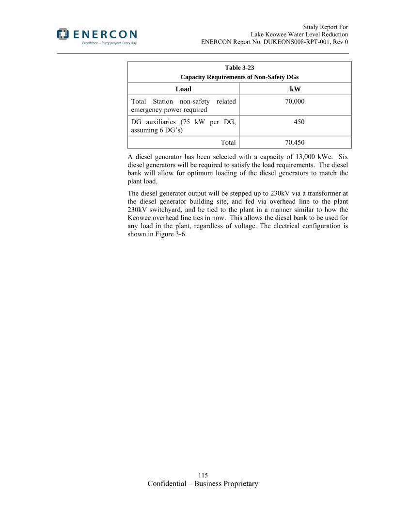
Study Report For Lake Keowee Water Level Reduction ENERCON Report No. DUKEONS008-RPT-001, Rev 0
115 Confidential – Business Proprietary
Table 3-23
Capacity Requirements of Non-Safety DGs
Load kW
Total Station non-safety related emergency power required
70,000
DG auxiliaries (75 kW per DG, assuming 6 DG’s)
450
Total 70,450
A diesel generator has been selected with a capacity of 13,000 kWe. Six diesel generators will be required to satisfy the load requirements. The diesel bank will allow for optimum loading of the diesel generators to match the plant load.
The diesel generator output will be stepped up to 230kV via a transformer at the diesel generator building site, and fed via overhead line to the plant 230kV switchyard, and be tied to the plant in a manner similar to how the Keowee overhead line ties in now. This allows the diesel bank to be used for any load in the plant, regardless of voltage. The electrical configuration is shown in Figure 3-6.

Study Report For Lake Keowee Water Level Reduction ENERCON Report No. DUKEONS008-RPT-001, Rev 0
116 Confidential – Business Proprietary
Figure 3-6, Part 2 Option 2 Non-Safety Related DG Configuration

Study Report For Lake Keowee Water Level Reduction ENERCON Report No. DUKEONS008-RPT-001, Rev 0
117 Confidential – Business Proprietary
Upgrades Needed to Existing Cables or Cable Routes
For Part 2 Option 2, the existing CCW pump cable trench will need to be modified to provide train separation for the CCW pump motor cables, as well as the control cables. The addition of motor cable separation requirements (Reference 8.45) for the entire trench path makes this a more challenging task compared to Part 1 Option 1a, and lowers the confidence level of the proposed solution, because more extensive and carefully coordinated shutdowns will likely be required. There is some overcrowding in a portion of the trench near the SSF system building, but external conduit, or a new portion of trench could be constructed to go around this area. In addition, there is crowding where the cables enter the turbine building which will need to be addressed with new routing. This is a more complex option, in some ways, than a new trench, but reworking of the trench appears to be feasible, and would be more cost-effective that a new trench.
Siting of Diesel Generators
Similar to Activity #2 for Part 1 Option 1a, an assessment of available site locations was based on an evaluation of the logistics and physical characteristics of each potential site. Site selection criteria were developed and each site considered was evaluated and ranked using the criteria to determine the optimum site(s). Because of the limited area available for diesel generator buildings, final site selection required multiple sites.
Eight sites were considered for possible diesel generator locations. Seven of the possible sites were located within the current OCA and one site was adjacent to the OCA across highway 183. Of the seven sites inside the OCA two were located within the existing PA perimeter. Of the eight sites considered, two sites were selected as the primary sites of interest with one site recommended overall. See Attachment 3 for the location of the potential locations considered.
The sites were ranked based on criteria including, but not limited to, the following:
Location
Proximity to terminus of loads
Security
o Vulnerability of duct bank
o Ability to construct new diesel buildings outside of the security perimeter, then move the fence
o Currently located inside security perimeter
Flood requirements
Exhaust fume impacts (including control room habitability)
Soil conditions
Impact on surrounding structures and their operational ability
Impact on plant personnel
Retaining structures required

Study Report For Lake Keowee Water Level Reduction ENERCON Report No. DUKEONS008-RPT-001, Rev 0
118 Confidential – Business Proprietary
Size of building
Permitting
Environmental Impact
Civil Site Evaluation Discussion
The following is an assessment of each of the eight sites based on civil considerations:
Site #1
Resides closely to an existing electrical pathway from Keowee Hydro, but is far away from the CCW pumps and the electrical trench is full according to Oconee’s original design criteria
No impact on surrounding structures
Requires a new protected area away from the existing PA
Removes an existing parking lot
Subject to complete destruction due to “External Flood Event”
Close to FERC Boundary – additional permitting required
Requires hazardous substance permit due to the parking lot being the cap for the site’s previous sewage waste
Not enough area to construct all diesel buildings at this location
Site #2
Subject to complete destruction due to “External Flood Event”
Resides close to the CCW pumps and existing duct bank to the current bus
Requires an extension of the existing PA
Not enough area to construct all diesel buildings at this location
Very small site
Impacts the PSW ductbank
Soil is saturated due to seepage from lake above
Site #3
Location is outside of the OCA
Requires a new protected area away from the existing PA
Connecting the site to the plant would be very difficult and costly
No impact on surrounding structures
May conflict with possible new power plant construction
Site #4
Location is near the CCW pumps

Study Report For Lake Keowee Water Level Reduction ENERCON Report No. DUKEONS008-RPT-001, Rev 0
119 Confidential – Business Proprietary
Flexibility such that the main construction activities would occur outside of the PA followed by an expansion of the existing PA to incorporate the new building
No impact on existing surrounding structures
Limits expansion capability of existing ISFSI to the north, but would not interfere with current plans to expand the ISFSI to the west
Not enough area to construct all diesel buildings at this location without impacting ISFSI expansion
Removes current site dumping ground for soil
Extensive grading and drainage
Above “External Flood Event” water levels
Site #5
Location is inside the existing PA
No security modifications required
Requires the removal of an existing warehouse
Adversely impacts control room habitability
Limits storage area and staging area inside PA
Costs will probably be associated with contaminated material disposal if any demolition is required
Not enough area to construct all diesel buildings at this location
Site #6
Location is inside the existing PA
Not enough area to construct all diesel buildings at this location
Above the current analysis for External Flood threat
Area inside of PA is already being looked at for water storage & Appendix R Warehouse.
Requires extensive soil removal
No impact on existing surrounding structures
Adversely impacts control room habitability
Above “External Flood Event” water levels
Site #7
No impact on surrounding structures
Requires a new protected area away from the existing PA
Removes an existing parking lot
Requires removal or relocation of existing CCW pipes
Subject to complete destruction due to “External Flood Event”
Not enough area to construct all diesel buildings at this location
Study Report For Lake Keowee Water Level Reduction ENERCON Report No. DUKEONS008-RPT-001, Rev 0
120 Confidential – Business Proprietary
Site #8
No impact on surrounding structures
Sewage Lagoon is decommissioned
Above the current analysis for External Flood threat
44kV Retail Substation is being looked at for a new transformer location (mitigation of External Flood)
Existing Warehouse is abandoned and can be removed
Flexibility such that the main construction activities would occur outside of the PA followed by an expansion of the existing PA to incorporate the new building
Not enough area to construct all diesel buildings at this location
Sites #2 and #7 would be very difficult to qualify as a safety related structure due to the low elevation of the sites and the external flood event scenario. Site #7 would impact the existing CCW discharge piping by requiring it to be relocated and as such is not a viable option. Site #6 is currently being considered for water storage tanks and a warehouse associated with Appendix R modifications. Site #5 is located in the existing PA near to the CCW pumps but would require the removal of an existing warehouse. Given the limited space inside of the current PA this would impact storage and planning within the PA. The exhaust from the diesel generators would adversely impact control room habitability at both site #5 and site #6. As a result, sites #2, #5, #6, and #7 are not recommended.
Site #1 is located near the existing trench from Keowee Hydro to the plant. Construction would not be able to occur near the existing trench due to the existing site criteria that the trench not be exposed for more than 72 hours. This site would require the removal of an existing parking lot, which is a problem given the limited parking inside the OCA. The parking lot at this location also serves as a topping cap for the site’s old sewage waste before the site connected to the local sewage system. Removing the parking lot would require hazardous permitting and any soil removal would add additional cost. The FERC boundary for the dam runs very close to this area and would require additional permitting. Restricting the site to stay between the FERC boundary and the existing Keowee trench would limit the area available for construction. This parking lot or the diesel generator building could potentially be moved further to the east; however, this site is subject to complete destruction due to “External Flood Event.”
Site #3’s location across highway 183 is the only option outside of the existing OCA. The main advantage of site #3 is that there is an abundance of space such that all the diesel buildings could be built at one location. The main disadvantage is that the site is far away from the PA and would require a new infrastructure to be built for both security and operations. The difficulty in protecting this site and the amount of infrastructure required make this site impractical. Furthermore, the site may be used for the location of a possible future power plant.

Study Report For Lake Keowee Water Level Reduction ENERCON Report No. DUKEONS008-RPT-001, Rev 0
121 Confidential – Business Proprietary
Site #8 is located just outside the PA in the vicinity of the old sewage lagoon. Construction at this site would occur outside of the existing PA, thus reducing security and construction costs, but would allow for the existing PA to be extended to capture the site once construction is finished. There are three items in this area that would be impacted. There is an abandoned warehouse and a sewage lagoon that would need to be removed. Since neither of these items are being used this would not impact the plant. There is an existing substation that would need to be relocated and there is adequate room across Rochester Highway.
Site #4 is located just outside the existing PA to the west of the ISFSI and near the CCW pumps. Construction at this site would occur outside of the existing PA, thus reducing security and construction costs, but would allow for the existing PA to be extended to capture the site once construction was finished. There would be no impact on existing structures. Future ISFSI expansions would still have enough room to expand to the west of their current site.
Site #3 is the only site considered where enough room is available to construct all of the diesel buildings in one location. However, given the undesirable location and additional costs associated with site #3 a composite of locations was considered using sites within the OCA. As a result a combination of sites #4 and #8 is recommended as the best sites for Part 2 Option 2. Sites #4 and #8 are close to each other and provide the best option based on adequate area, proximity to the power block and CCW pumps, not vulnerable to external flood event, no adverse control room habitability impacts, and maintaining only one security perimeter. Site #3 would be the most viable alternative to sites #4 and #8.
Electrical Evaluation of Sites 4 and 8
Eight sites were identified as possible locations for diesel generators at ONS. Attachment 3 shows the potential seven sites within the owner controlled area. Table 3-24 lists a summary of electrical suitability, with more detailed discussion following.
From an electrical perspective, the diesel generators should be located as close to their loads as possible. This is often not possible, as other considerations such as space availability and suitability of the site from a civil standpoint can easily take precedence over electrical proximity.
Such is the case with site selection for this study. Generally, civil and other factors drove the final selections.
The electrical discussion here is limited to a discussion of the two sites ultimately selected, since considerations greater than electrical proximity ultimately eliminated all of the other sites from further consideration. The two sites selected were sites #4 and #8.
For Part 2 Option 2, Site #4 was retained for the safety related diesel generator building. From an electrical perspective, it is closer than Site #8, since trenches must be used for safety related conductors, and the trench path is shorter from Site #4 than from Site #8.

Study Report For Lake Keowee Water Level Reduction ENERCON Report No. DUKEONS008-RPT-001, Rev 0
122 Confidential – Business Proprietary
For the commercial diesel generator bank, Site #8 has a more advantageous path available for the overhead line that feeds to the 230kV yard.
Table 3-24
Electrical Considerations for Potential Diesel Generator Sites, Part 2 Option 2
Location Suitability for Part1
#4 Closest option for Part 1, good possible path for electrical trench to tie in to CCW pumps. For Part 2, however, this option is quite a bit farther away, since safety-related buses will be fed directly, and they are located on the east side of the turbine building.
#8 No particular advantage electrically, since diesel generators for Part 2 feed to the 230kV yard. However, since overhead lines are planned for this feed, impact is minimal.
Civil Site Development Discussion
Site #4 is chosen for the location of the diesel generator building(s) to house 6 of the 12 diesel generator (i.e., the six safety related diesel generators). The building(s) will be located to the north of the future ISFSI expansion. Site #8 is chosen for the location of the diesel generator building(s) to house the other 6 of the 12 diesel generator (i.e., the six non-safety related diesel generators). See Attachment 5, Sheets S-002 and S-003 for site layout. Four major components comprise the site design for the diesel generator buildings:
Soil excavation
Retaining wall construction
Access road construction
Extended PA construction
Soil excavation is one of the major components of the site preparation for the new buildings. Because a majority of the site fill is organic soil, it is preferable to remove the soil and level the site such that new fill is only minimally required. The elevation of site #4 ranges from 820 ft at the boundary with the existing PA to 920 ft at the top of the hills next to highway 183. The location of the current soil storage area has a base elevation of approximately 895 ft. The soil storage area is to be removed and leveled to 890 ft over an area of approximately 3.5 acres. Additionally, the diesel generator building basement must have an additional excavation 30 ft deep and the size of the building. For site #4 it is estimated that approximately 1,800,000 ft3 of soil will be removed during construction for site work and an additional 770,000 ft3 of soil will be removed for the construction of the basement. A small amount of soil will be needed to fill the southwest corner of the site such that the extended PA fence will be at a constant height. The elevation of site #8 ranges from 800 ft on the south side of the site by the existing PA to 860 ft at the north side of the site. The aerated sewage lagoon will be removed and the soil will be leveled to 830 ft over an area of approximately 1.5 acres. Additionally, the diesel generator building basement must have an additional excavation 30 ft deep and the size of the building. For site #8 it is estimated that approximately 750,000 ft3 of soil will be

Study Report For Lake Keowee Water Level Reduction ENERCON Report No. DUKEONS008-RPT-001, Rev 0
123 Confidential – Business Proprietary
removed during construction for site work and an additional 770,000 ft3 of soil will be removed for the construction of the basement. Approximately 75,000 ft3 of fill will be needed at the southwest corner of site #8 for the construction of the retaining wall. Additional soil will also be required to fill the sewage lagoon. All soil that is excavated must remain on site and moved to a location determined by the site.
A concrete retaining wall is needed on the west side of site #4 as the leveled elevation is at 890 ft and the top of the hills next to highway 183 range from 890 ft to 920 ft. The retaining wall is to be located approximately 30 ft from the outer boundary of the extended PA fence. It runs approximately 600 linear feet along the western portion of the extended PA fence. A concrete retaining wall will also be needed to surround the building(s) at site #8 because of the constant slope of the site. A retaining wall is to be located wrapped around the northeast (elevation change from 830 ft to 860 ft) and southwest (elevation change from 815 ft to 830 ft) corners of the building layout. The two retaining walls combined run approximately 1500 linear feet.
For site #4 a temporary construction access road is to be constructed connecting the diesel generator building(s) to highway 183. It will branch off of the highway and travel approximately 550 ft to the site of the diesel generator building(s). A permanent road loops around the building(s) with enough space for trucks to turn and maneuver as required. A permanent access road will be constructed later and will connect the existing road on the east side of the PA and the diesel generator building(s). For site #8 a temporary construction access road is also to be constructed connecting the diesel generator building(s) to highway 183. It will branch off of the highway and travel approximately 300 ft to the site of the diesel generator building(s). A permanent road loops around the building(s) with enough space for trucks to turn and maneuver as required. A permanent access road will be constructed later and will connect the existing road on the east side of the PA and the diesel generator building(s). Because both of these permanent roads are located inside the PA, no gates will be required in the extended PA fence. Once the temporary roads are removed, security features will be installed to prevent any unwanted use.
After completion of the diesel generator buildings, the existing PA fence will be extended to encompass the buildings. For site #4 approximately 1830 linear feet of outside fence and 1770 linear feet of inside fence will be required for a total of 3600 linear feet of fence. A 20 ft gap between fences is paved with 12” deep of gravel equating to 36,600 ft3 of gravel. The fence fabric is supported every 10 feet by fence posts with concrete footings. The footings are 10” in diameter and 36” deep; 360 footings are required equating to 2340 ft3 of concrete for footings. The extended PA fence will be evenly sloped from elevation 855 feet to 800 feet on the north side of Site #4. The west PA fence will be sloped from 855 feet to 890 feet and then remain flat at 890 feet for the remainder of the fence directed south. The south portion of the fence will be flat at 890 feet and then slope from 890 feet to 820 feet directed east. For site #8 approximately 730 linear feet of outside fence and 715 linear feet of inside fence will be required for a total of 1450 linear feet

Study Report For Lake Keowee Water Level Reduction ENERCON Report No. DUKEONS008-RPT-001, Rev 0
124 Confidential – Business Proprietary
of fence. A 20 feet gap between fences is paved with 12” deep of gravel equating to 14,600 ft3 of gravel. The fence fabric is supported every 10 feet by fence posts with concrete footings. The footings are 10” in diameter and 36” deep; 145 footings are required equating to 950 ft3 of concrete for footings. The north part of the extended PA fence will gradually slope from 870 ft to 850 ft and have a steeper slope from 850 ft to 830 ft. The west part of the extended PA fence will be sloped from 830 ft to 800 ft. The area for all of the fence must be graded properly to ensure that a consistent slope is maintained for the functionality of the infrared cameras mentioned in the Security discussion of the report.
A building to house the transformers is also required. Because the transformer building must be in close proximity to the Turbine Building, it is proposed that it will be located on the north side of the East Yard (see Attachment 17). An access road of approximately 450 ft in length will be required to access the building. The west wall of the transformer building will be a retaining wall such that the access road can be run on the west side of the building. Approximately 80,000 cubic feet of dirt will be removed to construct the building.
Additionally, at site #8 a transformer pad is to be located to the north-northeast of the diesel generator building(s). This pad is approximately 80 ft x 45 ft and 6 ft deep with a 2 ft 6 inches deep oil containment trench which is capable of holding 15,250 gallons of oil. Another pad, 20 ft x 20 ft x 5 ft deep is located to the west of the transformer pad. This pad is for equipment associated with the transformer and the transmission lines.
Building Architectural Design Discussion
Part 2 Option 2 utilizes the Part 2 Option 1 grouping of six modules per building and positions them on two separate sites for a total of two buildings housing 12 diesel generator modules.
Building Structural Design Discussion
Part 2 Option 2 utilizes the Part 2 Option 1 grouping of six modules per building and positions them on two separate sites for a total of two buildings housing 12 generator modules. Foundation structural configuration are the same.
Electrical Design Discussion-Part 2-Supply all equipment now run off of Keowee Hydro
The safety related emergency power supply is discussed in Part 2 Option 1 – Safety related load replacement. This discussion will focus on the addition of diesel generators to power non-safety related loads.
A new diesel generator building is being added for six non-safety related diesel generators to power non-safety related plant loads. The six diesel generators in this building will tie to a common bus as load is added. This common 13.8kV bus will be stepped up to 230kV at a site adjacent to the diesel generator building, since the tie-in to the plant electrical system is at 230kV in the 230kV switchyard on the east side of the station. A new 90MVA, 13.8kV/230kV transformer will be located near the northeast corner

Study Report For Lake Keowee Water Level Reduction ENERCON Report No. DUKEONS008-RPT-001, Rev 0
125 Confidential – Business Proprietary
of the new diesel generator building. The 230kV line will be overhead, on a new transmission line routed around the north side of the station. The line will route to the outside of the existing PA, cross underneath the existing Jocasee line, and run parallel north of and along the Jocasee line to the 230kV switchyard. The line will tie-in at the same disconnect where Keowee overhead line ties in at present.
Cost Evaluation
The cost of the design and construction of the structures to house the diesel generators are summarized in Section 7 and Attachment 23.
3.2.2 Activity #2: Diesel Generator Support Systems and Equipment Required
Task Summary
Determine the systems and equipment required to support the operations of the diesel generators identified in Part 2 Activity #1 above.
Evaluation
These support systems are the same as detailed within Section 3.1.3 for Part 1 Option 1a.
3.2.3 Activity #3: Provide Detailed Evaluation of Feasibility
Task Summary:
Evaluate the feasibility of the options considered to allow operation of ONS at a Lake Keowee level as low as 777.1 feet, which would eliminate the dependence on the ECCW siphon for providing the necessary NPSH to the LPSW, HPSW and CCSW pumps following a LOCA concurrent with a loss of power for one unit and loss of offsite power on the other two units, and would eliminate the reliance on Keowee Hydro for supplying electrical power to the safety related loads and PSW system loads.
Permitting
Because the proposed diesel generators are a source of air pollutant, either an air permit or an explicit exemption from the appropriate environmental agency - Federal EPA or State/County environmental agency must be obtained. Based on preliminary information regarding the proposed diesel generators for Duke ONS, applicable South Carolina environmental regulations were reviewed, and informal, off-the-record discussions with air permitting personnel from the SCDHEC, BAQ, were conducted to provide a high level of confidence in the scope and budgetary estimates.
The proposed 13MW generators (six for Part 2 Option 1 and twelve for part 2 Option 2) will require a construction permit for the construction/installation of the units, under South Carolina Regulation 61-62. The specific type of construction permit application would have to be determined at the time of project initiation, and upon completion of an emissions inventory to determine the amount and type of emitted pollutants. The construction permit application would have to be reviewed and signed by a Professional

Study Report For Lake Keowee Water Level Reduction ENERCON Report No. DUKEONS008-RPT-001, Rev 0
126 Confidential – Business Proprietary
Engineer registered to practice in South Carolina. Once approved, the construction permit may become invalid if construction is not commenced within 18 months after receipt of approval. There is no application fee associated with the construction permit, unless an expedited construction permit is requested (cost estimate assumes it will be requested). If PSD is required, additional effort and cost would be needed. This would include air quality analysis, additional impacts analysis, and public involvement.
Once the diesel generators are installed, an air operating permit is required for the operation of the units. An evaluation (considering the specific diesel generator chosen) is needed to address the applicability of and ensure compliance with Title V of the Clean Air Act. This involves an assessment of the current status of the site’s air permit, and what the impact of adding the diesel generators will be. If the owner/operator or professional engineer in charge certifies construction as provided in the air construction permit, the permittee may operate the source in compliance with terms and conditions of the construction permit until the operating permit is issued by SCDHEC. Written notification to the SCDHEC of the actual date of initial startup must be submitted within 15 days after such date. No application fees are associated with the air operation permit.
Site development for the installation of the proposed diesel generators/buildings would require an SCDHEC NOI for Stormwater Discharges from Large and Small Construction Activities- NPDES General Permit SCR10000. As authorized by the Clean Water Act and regulated by the U.S. EPA, the NPDES permit program controls water pollution by regulating point sources that discharge pollutants into Waters of the U.S. The EPA authorizes states to administer their own NPDES permit program and South Carolina is an authorized state. The NOI includes multiple tasks to complete the permit. The estimate of work to complete the NOI is based on the following:
Prepare/complete the construction SWPPP and stormwater management calculations, design and drafting of SWPPP BMPs as required by the NOI.
Infiltration testing will likely be required and costs for tests have not been included in this study. This work should be coordinated with the geotechnical firm that would provide the soil borings and geotechnical investigation.
Calculations required to prepare the E&S plan as part of the NOI will be performed. BMPs will be used and every effort will be made to locate and use E&S BMPs that can be turned into permanent stormwater management BMPs. This will save construction dollars and limit earth disturbance.
Complete E&S calculations, design and draft of E&S devices, and prepare Maintenance Procedures for E&S.
Review 100 year flood plain and place on drawings. It is assumed that an FEMA map is available denoting 100 year floodplain.

Study Report For Lake Keowee Water Level Reduction ENERCON Report No. DUKEONS008-RPT-001, Rev 0
127 Confidential – Business Proprietary
Pre and post stormwater runoff calculations will be performed using the method of choice as designated by SCDHEC.
Permanent stormwater management plans will also be prepared.
ONS comments will be incorporated into the Final E&S Plan.
Drainage basin calculations will be based on a single drainage basin of 5 acres.
Scaled Maps of existing site and surrounding areas with two foot contours, boundaries, and improvements will be provided by Duke Energy as necessary.
The collection of survey data is not part of this study.
Payment of any applicable fees required by the NOI as part of this scope of work is not included in the cost estimate.
Identify and map Waters of the U.S. (e.g., wetlands, streams, etc.). Costs for identification of Waters of the U.S. are covered in the Section 404 Delineation Task which is discussed in a separate task item below.
Two infiltrations per acre will likely be needed (propose 30 tests at the 15 acre site). Soil borings are not included in the cost estimate; however, oversight for geotechnical firm that is providing the soil borings and geotech investigation should be coordinated.
As mentioned above, a delineation of Waters of the U.S. (i.e. wetlands, streams, ponds, etc.) will be required to complete the NOI. The delineation will identify and document the presence of Waters of the U.S. within the project area and include a formal delineation of these resources as specified in the Corps Wetlands Delineation Manual and the Interim Regional Supplements to the Corps Manual. Following the on-site investigations, a formal Section 404 delineation report will be prepared for submittal to the Corps. This report will contain materials required by the Corp’s Savannah District Regulatory Office for processing the delineation. The Corps allows consultants to prepare Section 404 delineations, but delineations are considered “preliminary” until they are approved by the Corps. If approved, the Corps will issue documentation of their approval via a JD letter.
The study does not include preparation of a Section 404 permit application (if in fact a permit is required). The findings presented in the delineation will document the presence or absence of Section 404 issues within the project area; this is a critical first step in the permitting process. If such resources are present, the delineation will provide details which will aid in (1) planning in support of avoidance and minimization efforts and (2) estimation and quantification of unavoidable project impacts. In addition, Section 404 wetland mitigation of impacts is not included in the cost estimate.
The addition of the above ground storage tanks for fueling the proposed diesel generators will prompt the requirement to update the facilities’ current operations SPCC and the operational SWPPP. It is assumed that the ONS Facility currently has an operational SPCC and SWPPP plan in place.

Study Report For Lake Keowee Water Level Reduction ENERCON Report No. DUKEONS008-RPT-001, Rev 0
128 Confidential – Business Proprietary
The update to the SPCC plan will require the following:
Site Inspection - conduct a site inspection after the completion of the proposed diesel generator buildings at the ONS facility by a Professional Engineer and/or their agent. ONS will provide access to the site, the current SPCC plan and any associated records. The inspection will be conducted to review the new diesel generator buildings and confirm any other potential changes since the development of the previous SPCC plan. This inspection is done to review any changes that may materially affect the existing SPCC Plan as required by SPCC regulation.
Prepare the revised Draft SPCC Plan and submit to ONS for review.
ONS Comments will be incorporated into the Final SPCC Plan. If the Facility is in compliance with 40 CFR 112, certification by a Professional Engineer will be provided.
The current operational SWPPP for the ONS facility based on the proposed diesel generator buildings will need to be revised. Information such as the current SWPPP and related information will be required to complete the update and assumes information will be obtained about the facility from onsite personnel. A separate site visit will not be required since a site visit is already anticipated for the SPCC update.
Assumptions for the SWPPP and SPCCC update tasks include:
SPCC regulation requirements such as AST Integrity Testing Program are not included in the cost estimate. Integrity testing of the new above ground storage tank(s) will be completed by the AST installation contractor. Integrity test will be needed to complete the SPCC Plan.
Preparation of a Facility Response Plan (40 CFR Part 109) is not included in the cost estimate.
Security Modifications
To determine the feasibility and cost of design changes to support operation of ONS with Lake Keowee level at 787 feet above mean sea level (msl), and also to support ONS operation with Lake Keowee level at 777.1 feet above msl, diesel generators are being added. The location and number of the diesel generators being considered by this study will require modifications to the Plant Security System and the current PA boundary will need to be reconfigured. The issues evaluated in this study include (but are not limited to) the reconfiguration/expansion of the plant PA. This study makes the following assumptions:
a. The proposed PA expansion will reconfigure and expand existing segments of the PA boundary referred to hereafter as the Security Isolation Zone.
b. Additional IDS zones will be created utilizing Infrared technology.

Study Report For Lake Keowee Water Level Reduction ENERCON Report No. DUKEONS008-RPT-001, Rev 0
129 Confidential – Business Proprietary
c. Existing IDS alarms are wired to multiplexers at various locations in the plant.
d. There are spare alarm inputs available at a multiplexer to accommodate IDS zones added by this modification.
e. As a result of adding IDS zones, additional cameras will be required to provide assessment of the new IDS zones. There are spare video inputs available in the video cabinet to accommodate the new cameras.
f. The IDS and assessment (cameras) systems are provided with a UPS in the event of a loss of normal AC power.
g. The plant security area lighting is provided with a UPS in the event of a loss of normal AC power.
h. In light of item g above, the cameras used for alarm assessment are not thermal cameras and are not equipped with Infrared illuminators.
i. A dedicated security ductbank system exists near the plant perimeter whereby cabling is routed from IDS and camera equipment to the plant security computer system.
j. BRE will be installed along the reconfigured isolation zone.
k. A temporary sally port will be installed in the isolation zone at the Site 4 area.
In accordance with the above mentioned assumptions, the following modifications to the PA boundary and Security Isolation Zone are expected to be made to accommodate the installation of the new diesel generators:
(1) Isolation Zone
The options for modifying the existing PA and nuisance fences that comprises the Security Isolation Zone are shown in Attachment 5. The extended PA fence and diesel generator buildings are situated such that they are away from highway 183 and not seen from outside of the plant due to the dense woods that surround the area. The extended PA was located such that the dense woods and other natural features would be as unaffected as possible.
(2) Intrusion Detection System
In accordance with NRC Regulatory Guide 5.44, Perimeter Intrusion Alarm Systems, the individual alarm segments should generally be limited to a length that allows observation of the entire segment by an individual standing at one end of the segment. This typically means that segments should not exceed 100 meters (328 feet), but shorter segments may be needed to achieve the desired performance. The lengths of the existing PA fence segments and position of the existing IDS equipment appear to comply with the regulatory position; however the proposed new Security Isolation Zone configuration will have segments that are greater than 328 feet in length. Therefore, to comply with the regulatory position and to account for changes in elevation due to the natural topography of the terrain, multiple IDS zones will be

Study Report For Lake Keowee Water Level Reduction ENERCON Report No. DUKEONS008-RPT-001, Rev 0
130 Confidential – Business Proprietary
installed in the reconfigured isolation zones. The new IDS zones will utilize Infrared technology in keeping with the existing ONS IDS technology.
(3) Cameras
A single fixed camera will be installed for each new or reconfigured Infrared IDS zone to provide assessment of an IDS alarm at the CAS and SAS. The cameras will be powered from an uninterruptible source of AC power. The make and model of the cameras will be consistent with those currently used at ONS. The cameras will be mounted on towers or poles consist with the existing camera design. A NEMA 4X camera termination box containing fiber converters, data modules and local circuit breakers will be mounted at the base of each pole.
(4) High Mast Area Lighting
It is proposed that 100 foot tall lighting poles with four (4) 1000 Watt fixtures each be installed to provide a minimum of 0.2 foot-candles of illumination measured horizontally at ground level in the isolation zones and appropriate exterior areas within the PA. The fixtures will be fed from an uninterruptible source of AC power to ensure continuous illumination for the camera fields of view in low light or nighttime hours in the event of a loss of normal AC power.
(5) Bullet Resistant Enclosures (BRE)
BREs will be installed inside the PA and along the new fence line. This study proposes that two (2) BREs will be installed at Site 4 and two (2) at Site 8. Each BRE will be provided with 208-120Vac utility power from a 208-120Vac distribution panel powered from a 480-208/120Vac, 10kVA transformer located at the base of each BRE. The BREs will be equipped with internal lighting and receptacles, external glare lighting and A/C.
(6) Temporary Sally Port
A temporary sally port may be installed in the isolation zone at the Site 4 area if the access road connecting to highway 183 is necessary. An electrically operated anti-ram vehicle barrier (i.e. wedge/bollard/drop arm barrier) with a K12/L3 rating in accordance with Department of State Standard SD-STD-02.01, Rev. A. “Test Method for Vehicle Crash Testing Of Perimeter Barriers and Gates” will be installed and operated from a BRE strategically located near the sally port.
(7) Ductbanks/Embedded Conduit
Additional ductbanks/embedded conduits will be installed from the existing ductbank/raceway system to provide a raceway path to the new and relocated lighting, IDS, and camera equipment. The ductbanks will include 6-4” diameter PVC conduits for 480Vac power to the yard area lighting, 480Vac power to the BRE transformers, 120Vac camera and IDS power, and fiber optic and data cabling. Two inch (2”) diameter rigid steel conduits will be direct buried from the manholes to the BREs, light poles, camera termination cabinets, and the IDS connection boxes.

Study Report For Lake Keowee Water Level Reduction ENERCON Report No. DUKEONS008-RPT-001, Rev 0
131 Confidential – Business Proprietary
(8) Cabling
Fiber optic and multi shielded pair signal cables will be routed from the IDS and camera terminal boxes to an alarm multiplexer and the CCTV video system cabinet for the new IDS zones and cameras. 480Vac power cables will be routed from the high mast light poles to a 480Vac, 3Ø power panel for the yard area security lighting. Similarly, 480Vac power cables will be routed from the BREs to a 480Vac, 3Ø power panel. Cables for the 120Vac power to the cameras and Infrared IDS will be routed from the terminal boxes of these components to a UPS backed distribution panel for a source of uninterruptible power to the detection and assessment systems in accordance with 10 CFR 73.55. Circuits feeding the existing IDS and camera components may be utilized to feed the new equipment if there is enough available margin on those circuits. This may eliminate the need to route extended lengths of new cables to source distribution panels.
(9) Grounding
A bare stranded copper conductor will be installed the full length of the new ductbanks and be connected to the existing ductbank/manhole grounding system at both ends. Conduits from the lights, camera and IDS equipment entering the new manholes will be connected in the manholes to the ductbank grounding system via conduit grounding locknuts or bushings. A separate ground loop will be installed at the base of the PA and nuisance fences and running the entire length of the fences. The BREs and fences will be grounded in accordance with the site grounding procedures. This fence ground loop will connect back into the existing plant ground grid at both ends of the fence loop.
(10) Security Computer System
The SCS database will be revised to incorporate the new IDS alarm zones as well as the camera video.
(11) CCW Pump Security Requirements
Upgrading of the CCW pumps to QA1 would require additional security protections to be installed at the pump locations. The protections necessary for the pumps would be required to ensure that in the event of an attack at ONS, the CCW pumps would remain in operation. The following security protections would be required at the CCW pump locations:
Installation of a Ballistic Barrier around the CCW Pumps
A ballistic barrier is required to be installed around the perimeter of the CCW pumps to ensure that an adversary is not capable of using a firearm to remove the CCW pumps from operation. The barrier would be designed using wide flange beam (W-sections) posts on 10 ft centers. The beams would be anchored to the pump foundation using baseplates and Hilti Kwik Bolt 3 anchor bolts. Ballistic steel plates, minimum 8 ft tall, would then be required to be attached to the wide flange sections encircling the pumps and preventing them from being damaged by an adversary. Due to the maintenance requirements on the pumps the ballistic steel barrier would be

Study Report For Lake Keowee Water Level Reduction ENERCON Report No. DUKEONS008-RPT-001, Rev 0
132 Confidential – Business Proprietary
required to be bolted together. Therefore, bolt holes would be required to be drilled through the ballistic plates and the flanges of the W sections to allow the plates to be bolted to the beams.
Buoy System
The CCW pumps at ONS are located in a cove along the shore of Lake Keowee. Therefore, the potential to remove the pumps from service using a water craft is possible unless a double layer buoy system is installed at the cove entrance. To ensure that a water craft is not capable of reaching the pumps it would be necessary to install a double layer buoy system at a distance greater than the minimum safe standoff distance for a design basis explosion. The double buoy system would provide a barrier that a water craft is not capable of circumventing ensuring that it remains a safe distance from the pumps.
Submerged Security Wall
To allow for security fencing and intrusion detection to be installed a concrete wall (minimum 2 ft thick) would be required to be installed at the north end of the CCW pump foundations. The wall would provide the footing and installation locations for a new 8 ft tall security fence as well as the new infrared intrusion detection system that would be required at this location. The wall and footing would be a reinforced concrete design with the footing for the wall resting on the lake floor. If the wall cannot be designed with a footing resting on the lake floor it would be necessary to excavate portions of the lake floor to allow the footing to be installed below the lake floor. The total height of the wall would gradually decrease as it approaches the shoreline though the top of the wall must be installed to ensure that it is equal to the height of the pump foundations.
Security PA Fence
Based on the QA1 classification of the CCW pumps, the PA fencing at ONS would need to be extended, such that the PA would enclose the existing pump locations. The new PA fence would be installed such that it tied into the existing PA fence along the east side of the ISFSI and just to the south of the Radwaste Building. Starting at the eastern edge of the ISFSI the fencing would run east across the dike until it intersected with the ballistic shielding installed along the southern edge of the intake structure. Due to the ballistic shielding being installed around the CCW pumps fencing would not be required on the intake structure, though the fencing would need to be installed along the new wall installed to the east of the intake structure. The fencing would run from the southeast corner of the intake structure platform across the top of the concrete wall and across the lake shore before tying back into the existing PA fence just to the south of the Radwaste Facility.

Study Report For Lake Keowee Water Level Reduction ENERCON Report No. DUKEONS008-RPT-001, Rev 0
133 Confidential – Business Proprietary
Infrared Intrusion Detection System
Based on the requirements of 10CFR73 it is necessary to have an IDS capable of providing an alarm prior to an adversary reaching the PA boundary. Therefore, an infrared intrusion detection system would be required to be installed outside of the PA boundary described in the section above. The installation of the IDS system would create a minimum of three (3) new IDS zones that would be required to be monitored, which would consist of a minimum of 4 new IDS posts with sensors. The three zones would be laid out such that the first zone would be located between the fence tie in to the east of the ISFSI and the southwestern edge of the intake structure platform. Zone two would be across the southern edge of the intake platform just outside of the ballistic barrier, while Zone 3 would be between the southeastern edge of the intake platform and the fence tie in location south of the Radwaste Facility. Two of the IDS posts would be installed using concrete foundations, while the two located at the corners of the intake platform would be required to be installed using a baseplate and anchor bolts.
PA Cameras
A minimum of 4 new PA cameras would be required to be installed along the revised PA boundary to ensure that security is able to assess and detect possible alarms along this boundary. Two of the cameras would be required to be installed such that the cameras were able to view along the fence line located on the south side of the intake structure. The remaining two cameras would be installed at the fence tie in locations to ensure that the new fencing routed along the shoreline is able to be viewed. Depending on the capabilities of the cameras it is possible that additional cameras would be required along the fence to ensure that security is able to maintain adequate surveillance along the revised PA.
Evaluation
The feasibility of eliminating dependence on ECCW siphon flow (following a LOCA concurrent with loss of power) and eliminating reliance on Keowee Hydro by providing safety-related emergency diesel generators centers around the same issues as have already been discussed in Section 3.1.11.

Study Report For Lake Keowee Water Level Reduction ENERCON Report No. DUKEONS008-RPT-001, Rev 0
134 Confidential – Business Proprietary
4.0 Impact On Licensing Basis
A review of the Oconee licensing basis was performed to determine the impact of implementing the various options evaluated. The primary focus of the review was to determine if the upgrades could be accomplished under 10CFR50.59 or if a License Amendment Request (LAR) would be required. This impact review concluded that an LAR is required to support implementation of four of the five options evaluated in Sections 3.1 and 3.2. Summaries of this licensing basis impact review are discussed below.
4.1 Consideration of Implementation Under 10 CFR 50.59 Process
A preliminary licensing impact review was performed for each of the five options considered in the study as discussed below:
4.1.1 Part 1 Option 1a
To allow lake Keowee to be drawn down to at least 787 feet during normal plant operation, upgrade twelve CCW pumps and motors and the associated CCW discharge valves and motors to QA1, and power them from three safety-related diesel generators. The preliminary review determined that an LAR is required to make the following amendments to the Operating License:
Section 3.7.8, Emergency Condenser Circulating Water (ECCW) System: This Technical Specification would be modified to delete the ECCW system and to include the CCW pumps and valves that are upgraded to QA-1 since the utilization of the CCW pumps would negate the need for the ECCW system. This specification would then control operability requirements of the CCW system for providing cooling water to the LPSW, HPSW and CCSW systems. Appropriate Conditions, Required Actions, Completion Times, Surveillances, and Allowed Out-of-Service Times would be developed and included.
Section 3.8.1, AC Sources – Operating: The three new diesel generators would be added to this Technical Specification to ensure appropriate limits are applied for the safety related diesel generator Operability requirements. Appropriate Conditions, Required Actions, Completion Times, Surveillances, and Allowed Out-of-Service Times would be developed and included.
Section 3.8.2, AC Sources – Shutdown: Diesel generators would be added to this specification to ensure that appropriate limitations and controls are applied to whichever new diesel generators are required to support operability of required CCW pumps during Shutdown conditions.
Section 3.8.3, DC Sources – Operating: New batteries required for control and indication of the new safety related diesel generators and output breakers would be added to this specification. Appropriate Conditions, Required Actions, Completion Times, Surveillances,

Study Report For Lake Keowee Water Level Reduction ENERCON Report No. DUKEONS008-RPT-001, Rev 0
135 Confidential – Business Proprietary
Allowed Out-of-Service Times, and Battery Cell Parameters would be developed and included.
Section 3.8.4, DC Sources – Shutdown: This specification would be amended to add operability controls during Shutdown conditions for the new CCW diesel generator batteries described in Section 3.8.3 above.
Section 3.8.5, Battery Cell Parameters: This specification would be amended to add the batteries for the diesel generator batteries.
Section 3.8.8, Distribution Systems – Operating: This specification would be amended (as necessary) to add the new electrical distribution system (breakers, busses, and/or panels) that provides the power distribution path from the new diesel generators to the CCW pumps that are upgraded to QA-1.
Section 3.8.9, Distribution Systems – Shutdown: This specification would be amended to add operability controls during Shutdown conditions for the new CCW diesel generator electrical distribution system described in Section 3.8.8 above.
Section 3.8.X, Diesel Fuel Oil, Lube Oil, and Starting Air: A new specification will be added to the Technical Specifications to provide controls and limitations on the required auxiliary systems of the new safety related diesel generators. Attachment 18 provides an example of a proposed new specification.
Section 5.5.X, CCW Emergency Diesel Fuel Oil Testing Program: A new program similar to the one described in 5.5.14, would be added to include the fuel oil for the new diesel generators.
Additionally, significant changes to the Oconee Units 1, 2 and 3 UFSAR and Technical Specification Bases will be required to reflect the proposed changes if this option is chosen.
4.1.2 Part 1 Option 1b
Reducing required NPSH for LPSW and HPSW pumps (by reducing required flow during a site wide LOOP and a LOCA) and installing a booster pump to increase available head for the CCSW pumps will allow Lake Keowee to be drawn down to at least 787 feet during normal plant operations. A 50.59 Evaluation will be required for these modifications. A preliminary Evaluation (see Attachment 26) determined that an LAR may not be required, as functions and ability to perform required functions by safety related SSCs are not impacted by the modifications implemented in this option. Changes will be required to the SLC and UFSAR to reflect the proposed changes if this option is chosen.
There is the potential requirement for an LAR with this option because it raises the question as to how many days of KHU operation will be available following an LOOP event. As stated in Section 1.2, Background, “Water inventory in Lake Keowee must allow greater than7 days of Keowee Hydro

Study Report For Lake Keowee Water Level Reduction ENERCON Report No. DUKEONS008-RPT-001, Rev 0
136 Confidential – Business Proprietary
generator operation during certain emergency situations involving loss of normal AC power to Oconee. The required lake level to support this function is greater than 787 ft.”
ONS has a unique licensing basis regarding safety systems and their response to a LOOP event. There is no requirement in Technical Specifications or the UFSAR which states that a minimum lake level is required to ensure a minimum number of days of KHU operation. SLC 16.9.7.j states that this limit is 787 ft. msl. Preliminary calculations done for this study conclude that implementation of these modifications provides sufficient NPSH available for LPSW and HPSW pump operation at lake levels down to 787 ft. msl. The question becomes one of whether there is an increased risk to plant operations, beyond what the NRC has previously reviewed and approved, if lake level is anywhere between the current limit specified by SLC 16.9.7.a of 793.7 ft and the 787 ft. that is feasible with these modifications. The System Commitment for SLC 16.9.7.j states that neither Keowee Hydro nor Oconee Nuclear Station should be considered inoperable at this (787 ft.) lake level. The proposed modifications do not impose additional restrictions or limitations on these conditions.
4.1.3 Part 1 Option 1c
To allow Lake Keowee to be drawn down to at least 787 feet during normal plant operation, upgrade twelve CCW pumps and motors and the CCW discharge valves and motors to QA1, and power them from the Keowee Hydro Units for emergency safety related power. The preliminary review determined that an LAR is required to make the following amendments to the Operating License:
Section 3.7.8, Emergency Condenser Circulating Water (ECCW) System: This Technical Specification would be modified to delete the ECCW system and to include the CCW pumps and valves that are upgraded to QA-1 since the utilization of the CCW pumps would negate the need for the ECCW system. This specification would then control operability requirements of the CCW system for providing cooling water to the LPSW, HPSW and CCSW systems. Appropriate Conditions, Required Actions, Completion Times, Surveillances, and Allowed Out-of-Service Times would be developed and included.
Section 3.8.1, AC Sources – Operating: Reference to the new underground feeder from Keowee Hydro for the CCW pumps and valves would be added to this Technical Specification in addition to any new surveillance required for the new feeder breakers.
Section 3.8.2, AC Sources – Shutdown: Reference to the new underground feeder from Keowee Hydro for the required CCW pumps and valves would be added to this Technical Specification in addition to any new surveillance required for the new feeder breakers.

Study Report For Lake Keowee Water Level Reduction ENERCON Report No. DUKEONS008-RPT-001, Rev 0
137 Confidential – Business Proprietary
Section 3.8.3, DC Sources – Operating: New batteries may be required for control of the new safety related switchgear added for the new Keowee Hydro feed to the CCW pumps and valves and would be added to this specification. Appropriate Conditions, Required Actions, Completion Times, Surveillances, Allowed Out-of-Service Times, and Battery Cell Parameters would be developed and included.
Section 3.8.4, DC Sources – Shutdown: This specification would be amended to add operability controls during Shutdown conditions for the new CCW switchgear batteries described in Section 3.8.3 above.
Section 3.8.8, Distribution Systems – Operating: This specification would be amended (as necessary) to add the new electrical distribution system (breakers, busses, and/or panels) that provides the power distribution path from Keowee Hydro to the CCW pumps and valves that are upgraded to QA-1.
Section 3.8.9, Distribution Systems – Shutdown: This specification would be amended to add operability controls during Shutdown conditions for the new electrical distribution system described in Section 3.8.8 above.
Additionally, significant changes to the Oconee Units 1, 2 and 3 UFSAR and Technical Specification Bases will be required to reflect the proposed changes if this option is chosen.
4.1.4 Part 2 Option 1
To allow Lake Keowee to be drawn down to at least 777.1 feet during normal plant operation, replace the underground safety related power supply from Keowee Hydro with safety related diesel generators sufficient in size and number to power emergency loads during a site wide LOOP and a LOCA on one unit or supply the PSW loads. The preliminary review determined that an LAR is required to make the following amendments to the Operating License:
Section 3.3.17, Emergency Power Switching Logic (EPSL) Automatic Transfer Function: Because the diesel generator will supply emergency power for the safety related loads under Part 2 Option 1 instead of Keowee Hydro, this Technical Specification and bases should be reviewed for impact.
Section 3.3.18, Emergency Power Switching Logic (EPSL) Voltage Sensing Circuits: Because the diesel generator will supply emergency power for the safety related loads under Part 2 Option 1 instead of Keowee Hydro, this Technical Specification and bases should be reviewed for impact.
Section 3.3.19, Emergency Power Switching Logic (EPSL) 230 kV Switchyard Degraded Grid Voltage Protection (DGVP): Because the diesel generator will supply emergency power for the safety related

Study Report For Lake Keowee Water Level Reduction ENERCON Report No. DUKEONS008-RPT-001, Rev 0
138 Confidential – Business Proprietary
loads under Part 2 Option 1 instead of Keowee Hydro, this Technical Specification and bases should be reviewed for impact.
Section 3.3.20, Emergency Power Switching Logic (EPSL) CT-5 Degraded Grid Voltage Protection (DGVP): Because the diesel generator will supply emergency power for the safety related loads under Part 2 Option 1 instead of Keowee Hydro, this Technical Specification and bases should be reviewed for impact.
Section 3.3.21, Emergency Power Switching Logic (EPSL) Keowee Emergency Start Function: Because diesel generators will supply emergency power for the safety related loads under Part 2 Option 1 instead of Keowee Hydro, this Technical Specification would be revised to reflect the emergency diesel generators.
Section 3.3.22, Emergency Power Switching Logic (EPSL) Manual Keowee Emergency Start: Because Keowee Hydro would not be required to supply emergency power for the safety related loads under Part 2 Option 1, this Technical Specification would be moved from the Operating License to the Select License Commitments document.
Section 3.7.8, Emergency Condenser Circulating Water (ECCW) System: This Technical Specification would be modified to delete the ECCW system and to include the CCW pumps and valves that are upgraded to QA-1 since the utilization of the CCW pumps would negate the need for the ECCW system. This specification would then control operability requirements of the CCW system for providing cooling water to the LPSW, HPSW and CCSW systems. Appropriate Conditions, Required Actions, Completion Times, Surveillances, and Allowed Out-of-Service Times would be developed and included.
Section 3.8.1, AC Sources – Operating: For Part 2 Option 1 new safety related diesel generators would be installed to supply all of the safety related loads. The new emergency diesel generators would be added to this Technical Specification to ensure appropriate limits are applied for the safety related Diesel Operability Requirements. Appropriate Conditions, Required Actions, Completion Times, Surveillances, and Allowed Out-of-Service Times would be developed and included. Since Keowee Hydro would not be required to supply safety related loads, Keowee Hydro would be moved from this specification to the Select License Commitments Document.
Section 3.8.2, AC Sources – Shutdown: Diesel generators would be added to this specification to ensure that appropriate limitations and controls are applied to the minimum number of diesel generators required to support operability of required safety related systems during Shutdown conditions. Since Keowee Hydro would not be required to supply safety related loads during Shutdown, Keowee

Study Report For Lake Keowee Water Level Reduction ENERCON Report No. DUKEONS008-RPT-001, Rev 0
139 Confidential – Business Proprietary
Hydro would be moved from this specification to the SLC Document.
Section 3.8.3, DC Sources – Operating: New batteries required for control and indication of the new safety related diesel generators and output breakers would be added to this specification. Appropriate Conditions, Required Actions, Completion Times, Surveillances, Allowed Out-of-Service Times, and Battery Cell Parameters would be developed and included.
Section 3.8.4, DC Sources – Shutdown: This specification would be amended to add operability controls during Shutdown conditions for the new diesel generator batteries described in Section 3.8.3 above.
Section 3.8.5, Battery Cell Parameters: Because the Keowee Hydro Units would no longer be supplying safety related loads this specification for the Keowee Hydro batteries would be moved from the Operating License to the SLC. The batteries for the diesel generator batteries would be added to this specification.
Section 3.8.8, Distribution Systems – Operating: This specification would be amended (as necessary) to add the new electrical distribution system (breakers, busses, and/or panels) that provides the power distribution path from the new diesel generators to the safety related equipment. Additionally, any breakers, busses, and/or panels that are specific to Keowee Hydro would be moved to the SLC if they are currently within the scope of this specification.
Section 3.8.9, Distribution Systems – Shutdown: This specification would be amended to add operability controls during Shutdown conditions for the new CCW diesel generator electrical distribution system described in Section 3.8.8 above. Additionally, any breakers, busses, and/or panels that are specific to Keowee Hydro would be moved to the SLC if they are currently within the scope of this specification.
Section 3.8.X, Diesel Fuel Oil, Lube Oil, and Starting Air: A new specification will be added to the Technical Specifications to provide controls and limitations on the required auxiliary systems of the new safety related diesel generators. Attachment 18 provides an example of a proposed new specification.
Section 5.5.X, Emergency Diesel Fuel Oil Testing Program: A new program similar to the one described in 5.5.14, would be added to include the fuel oil for the new diesel generators.
Additionally, significant changes to the Oconee Units 1, 2 and 3 UFSAR and Technical Specification Bases will be required to reflect the proposed changes if this option is chosen.

Study Report For Lake Keowee Water Level Reduction ENERCON Report No. DUKEONS008-RPT-001, Rev 0
140 Confidential – Business Proprietary
4.1.5 Part 2 Option 2
To allow Lake Keowee to be drawn down to at least 777.1 feet during normal plant operation, replace the underground safety related power supply and the overhead non-safety related power supply from Keowee Hydro with diesel generators sufficient in size and number to power emergency loads during a site wide LOOP and a LOCA on one unit and additionally power non-safety related BOP loads now powered from Keowee Hydro overhead line. Additionally, the diesel generators are capable of supplying the PSW system. This option eliminates the requirement for the hydro unit. The preliminary review determined that an LAR is required to make the following amendments to the Operating License:
Section 3.3.17, Emergency Power Switching Logic (EPSL) Automatic Transfer Function: Because the diesel generators will supply emergency power for the safety related and non-safety related loads under Part 2 Option 2 instead of Keowee Hydro, this Technical Specification and bases should be reviewed for impact.
Section 3.3.18, Emergency Power Switching Logic (EPSL) Voltage Sensing Circuits: Because the diesel generators will supply emergency power for the safety related loads and non-safety related loads under Part 2 Option 2 instead of Keowee Hydro, this Technical Specification and bases should be reviewed for impact.
Section 3.3.19, Emergency Power Switching Logic (EPSL) 230 kV Switchyard Degraded Grid Voltage Protection (DGVP): Because (during Loss of Offsite Power) the new safety related diesel generators and non-safety related DGs would be providing power to all loads (safety related and select non safety related respectively) currently supplied by Keowee Hydro (using underground and overhead lines) this specification would need to be amended. (See the Required Action for Condition D of the TS 3.3.19).
Section 3.3.20, Emergency Power Switching Logic (EPSL) CT-5 Degraded Grid Voltage Protection (DGVP): Because the diesel generators will supply emergency power for the safety related loads and non-safety related loads under Part 2 Option 2 instead of Keowee Hydro, this Technical Specification and bases should be reviewed for impact.
Section 3.3.21, Emergency Power Switching Logic (EPSL) Keowee Emergency Start Function (Modes 1, 2, 3, and 4): Because diesel generators will supply emergency power for the safety related loads and non-safety related loads under Part 2 Option 2 instead of Keowee Hydro, this Technical Specification would be revised to reflect the emergency diesel generators.
Section 3.3.22, Emergency Power Switching Logic (EPSL) Manual Keowee Emergency Start Function (Modes 5 and 6): Because Keowee Hydro would not be required to supply emergency power for the safety related or non-safety related loads under Part 2 Option

Study Report For Lake Keowee Water Level Reduction ENERCON Report No. DUKEONS008-RPT-001, Rev 0
141 Confidential – Business Proprietary
2, this Technical Specification would be removed from the Operating License.
Section 3.7.8, Emergency Condenser Circulating Water (ECCW) System: This Technical Specification would be modified to delete the ECCW system and to include the CCW pumps and valves that are upgraded to QA-1 since the utilization of the CCW pumps would negate the need for the ECCW system. This specification would then control operability requirements of the CCW system for providing cooling water to the LPSW, HPSW and CCSW systems. Appropriate Conditions, Required Actions, Completion Times, Surveillances, and Allowed Out-of-Service Times would be developed and included.
Section 3.8.1, AC Sources – Operating: For Part 2 Option 2 new safety related diesel generators would be installed to supply all of the safety related loads and new non-safety related diesel generators would be installed to supply the supplemental non-safety related loads (all those currently supplied by KHUs 1 and 2). The new safety related diesel generators that supply the safety related loads would be added to this Technical Specification to ensure appropriate limits are applied for the safety related diesel generator Operability requirements. Appropriate Conditions, Required Actions, Completion Times, Surveillances, and Allowed Out-of-Service Times would be developed and included. The non-safety related diesel generators that supply the non-safety related loads would be added to the SLC. Since Keowee Hydro would not be required to supply any loads, Keowee Hydro would be removed from the Operating License.
Section 3.8.2, AC Sources – Shutdown: Diesel generators that supply the safety related loads would be added to this specification to ensure that appropriate limitations and controls are applied to the minimum number of diesel generators required to support operability of required safety related systems during Shutdown conditions. If determined necessary the diesel generators that supply the non-safety related loads would be added to the SLC. Since Keowee Hydro would no longer be required to supply any loads during Shutdown, Keowee Hydro would be removed from this specification.
Section 3.8.3, DC Sources – Operating: New batteries required for control and indication of the new safety related diesel generators and output breakers would be added to this specification. The batteries used to support the diesel generators that supply the non-safety related loads would be added to the SLC. Appropriate Conditions, Required Actions, Completion Times, Surveillances, Allowed Out-of-Service Times, and Battery Cell Parameters would be developed and included. Additionally, any DC sources that are specific to Keowee Hydro would be removed from the Operating License.

Study Report For Lake Keowee Water Level Reduction ENERCON Report No. DUKEONS008-RPT-001, Rev 0
142 Confidential – Business Proprietary
Section 3.8.4, DC Sources – Shutdown: This specification would be amended to add operability controls during Shutdown conditions for the new diesel generator batteries described in Section 3.8.3 above. Additionally, any DC sources that are specific to Keowee Hydro would be removed from the Operating License.
Section 3.8.5, Battery Cell Parameters: Because the Keowee Hydro Units would no longer be supplying any plant loads this specification for the Keowee Hydro batteries would be amended to remove from the Operating License. The batteries for the diesel generator batteries would be added to this specification.
Section 3.8.8, Distribution Systems – Operating: This specification would be amended (as necessary) to add the new electrical distribution system (breakers, busses, and/or panels) that provides the power distribution path from the new diesel generators to the safety related equipment. Additionally, the new electrical distribution system (breakers, busses, and/or panels) that are specific to the diesel generators supplying the non-safety related loads could be included to the SLC. Additionally, any breakers, busses, and/or panels that are specific to Keowee Hydro would be removed from the Operating License.
Section 3.8.X, Diesel Fuel Oil, Lube Oil, and Starting Air: A new specification will be added to the Technical Specifications to provide controls and limitations on the required auxiliary systems of the new safety related diesel generators. Attachment 18 shows the proposed new specification. A similar specification for the non-safety related diesel generators could be added to the SLC.
Section 5.5.X, Emergency Diesel Fuel Oil Testing Program: A new program similar to the one described in 5.5.14, would be added to include the fuel oil for the new diesel generators.
5.5.18 KHU Commercial Power Generation Testing Program: This specification would be amended or eliminated to reflect that Keowee Hydro is no longer required as an emergency power supply.
Additionally, significant changes to the Oconee Units 1, 2 and 3 UFSAR and Technical Specification Bases will be required to reflect the proposed changes if this option is chosen.
4.2 Implementation Phase
The phasing for the implementation of the project was reviewed to determine what plant conditions would be necessary to implement each of the various options.
4.2.1 Part 1 Option 1a
Construction activities for installation of the new emergency diesel generators could be performed with all three units of Oconee on-line. Upgrade of CCW pumps to QA-1 can be performed one at a time while the units remain on-line. Electrical tie-in of new diesel generators and
Study Report For Lake Keowee Water Level Reduction ENERCON Report No. DUKEONS008-RPT-001, Rev 0
143 Confidential – Business Proprietary
switchgear, installation of new cables to CCW pumps/valves, and upgrade of CCW pump discharge valves will require unit outages.
4.2.2 Part 1 Option 1b
Modifications proposed for this option will generally require that installation be performed during unit outages.
Installation of flow-limiting devices for LPSW to the Unit 1 and Unit 2 component coolers (options L2 and L3 of Tables 3-11 and 3-12) require Unit 1 and Unit 2 coincident outages. Unit 1 and Unit 2 component coolers are supplied from a common header and along with radiation monitoring coolers will be out of service during installation. Installation of options L2/L3 for Unit 3 will require a Unit 3 outage.
Installation of flow-limiting devices for LPSW to the RCP coolers will require all RCPs be out of service on a Unit basis. Therefore installation of this modification will require individual unit outages for safe implementation.
Installation of a booster in the supply line from CCW crossover header to the CCSW pumps will likely require all three units be in an outage, assuming double isolation is required. There is only one isolation valve, CCW-460, between the CCW crossover header and the location proposed for the booster pump. Limited access to this 10” line precludes the use of a freeze plug as a second isolation device. There is an alternate source of water to the CCSW pumps from the LPSW system through valve LPSW-135 if single point isolation is acceptable.
Installation of the proposed HPSW modifications can be performed while the units remain at power; however the discharge valve of each HPSW pump will need to be isolated by means of a freeze seal or some other method in order to permit installation without impacting the entire HPSW/Fire Water system.
4.2.3 Part 1 Option 1c
Construction activities for installation of the new ductbank from Keowee Hydro to the new switchgear building for the CCW pumps could be performed with all three units of Oconee on-line. Upgrade of CCW pumps to QA-1 can be performed one at a time while the units remain on-line. Electrical tie-in of new Keowee Hydro supply and switchgear may require all three units to be shut down if tie-ins to the Keowee Hydro Powerhouse bus cannot be completed within the LCO limitations for Keowee Hydro electrical system being out of service. Installation of new cables to CCW pumps/valves, and upgrade of CCW pump discharge valves will require unit outages.
4.2.4 Part 2 Option 1
Construction activities for installation of the new emergency diesel generators can be performed with all three units of Oconee on-line. Upgrade of CCW pumps to QA-1 can be performed one at a time while the units

Study Report For Lake Keowee Water Level Reduction ENERCON Report No. DUKEONS008-RPT-001, Rev 0
144 Confidential – Business Proprietary
remain on-line. Electrical tie-in of new diesel generators and switchgear, installation of new cables to CCW pumps/valves, and upgrade of CCW pump discharge valves will require unit outages. Electrical tie-in to the PSW system will require the system to be taken out of service.
4.2.5 Part 2 Option 2
Construction activities for installation of the new emergency diesel generators and non-safety diesel generators can be performed with all three units of Oconee on-line. Upgrade of CCW pumps to QA-1 can be performed one at a time while the units remain on-line. Electrical tie-in of new diesel generators and switchgear, installation of new cables to CCW pumps/valves, and upgrade of CCW pump discharge valves will require unit outages. Electrical tie-in to the PSW system will require the system to be taken out of service.
5.0 Plant Impacts
Various searches were performed on the ONS network to identify potential station impacts created by the proposed options. This included existing design output such as drawings, specifications, calculations, and licensing documents, plant procedures such as operating procedures and maintenance procedures, and plant program impacts. Although a significant effort was made to develop a complete and comprehensive listing of all plant impacts, this should be considered a preliminary listing, as additional plant impacts will likely be identified in the final design process. These plant impacts are discussed on a summary level in this section, and a comprehensive itemized listing is included as Attachment 19.
5.1 Design documentation
The type and number of impacted design documents are summarized below:
No. of Docs Impacted for Each Option
Document Type 1-1a 1-1b 1-1c 2-1 2-2
Licensing * 36 13 28 48 43
Design Basis Specifications 31 5 18 32 43
System Calculations 44 22 11 46 49
Design Drawings 1442 117 277 2068 3261
* This item indicates the number of different sections that will be impacted in the Technical Specifications, UFSAR and Select License Commitments.
The existing licensing and design basis documents will require significant revisions. However, the design effort for equipment specifications, drawings, and calculations will be more impactive, since some of the new systems, structures and components will be safety-related and seismically qualified.
See Attachment 19 for a listing of the various design documents expected to be impacted and/or newly developed that would be required for the different options evaluated by this study.

Study Report For Lake Keowee Water Level Reduction ENERCON Report No. DUKEONS008-RPT-001, Rev 0
145 Confidential – Business Proprietary
In addition to the documents specified in the above summary and in Attachment 19, for the option chosen it will be necessary to perform a thorough review of the Site Safety Analysis and core thermal hydraulic calculations including, the Areva documents that support them.
5.2 Procedural
The type and number of impacted plant procedures are summarized below:
No. of Docs Impacted for Each Option
Document Type 1-1a 1-1b 1-1c 2-1 2-2
Operating Procedures 71 50 61 68 68
Periodic Test Procedures 165 27 24 165 165
Maintenance Procedures 115 0 115 115 115
Other System-Related Procedures 3 0 0 3 3
Due to the extent of changes to existing systems, the required revisions to the above listed documents should be considered as very extensive. Many procedures will require total rewrites due to wholesale changes in system components and operating schemes. In addition to the required revisions to existing procedures, a number of new procedures will also be required.
See Attachment 20 for a listing of the procedures expected to be impacted and new procedures that would be required for the different options evaluated by this study.
Attachment 21 provides an example of preventive maintenance (PM) tasks that would be expected to be part of the PM program for new diesel generators.
5.3 Programmatic
Several programs were identified as affected by the proposed options. Although some program impacts will be relatively minor, other programs will be significantly impacted depending on the options chosen. Notably, the Inservice Inspection (ISI) and Inservice Testing (IST) Programs, the Motor Operated Valve (MOV) Program, and the PM program will require significant changes to reflect the upgraded and new safety related systems, structures and components for the options requiring the most extensive design changes.
Additionally, Extensive Damage Mitigation Strategies (B.5.b) commitments are affected by lowering lake levels. Currently, per information obtained from site personnel, the location from which the B.5.b pump provides makeup water to the B.5.b loads is at elevation 802 feet and the pump itself is 3 feet higher at 805 feet. The pump is a Hale FP1500 with a 15 ft maximum suction head lift. Therefore, if lake level is lowered to less than 790 feet the suction head lift of the pump will be insufficient to pump water. This would require either placement of the pump at lower elevation or replacing the Hale FP1500 pump with a different model.

Study Report For Lake Keowee Water Level Reduction ENERCON Report No. DUKEONS008-RPT-001, Rev 0
146 Confidential – Business Proprietary
6.0 Project Schedules Project schedules for each option are included as Attachment 22. The schedules address the primary phases of each option:
The design phase, moving from the conceptual design described in this report through to the final design as issued in the respective Engineering Change Packages, and continuing through the implementation phase with field support.
The procurement phase, for those options requiring new systems, structures and/or components, with durations for long-lead items based on vendor estimates.
The implementation phase, with durations based on industry standard estimating techniques such as described in the RS Means (Factored Construction Cost Data) manual (depending on the option chosen), with input from ONS personnel based on site-specific knowledge.
The focus is on accurate durations for each phase, as the stated durations can be applied to any desired start date to determine an estimated completion date. Required system outage durations are clearly identified for the implementation phase of the project.

Study Report For Lake Keowee Water Level Reduction ENERCON Report No. DUKEONS008-RPT-001, Rev 0
147 Confidential – Business Proprietary
7.0 Economic Estimates and Overall Project Costs
Project design, procurement, implementation, and operations and maintenance (O&M) cost estimates, are included as Attachments 23 and 24. The intent of this section is to provide an estimate of the total project cost for each option, both to support cost-benefit assessments of the project, as well as to define the necessary funding required to be budgeted for the full scope of work. The estimates are based on today’s dollars and contain no allowance for escalation.
7.1 Initial Capital Costs
7.1.1 Design
Design cost estimates for Part 1 Options 1a & 1c and Part 2 Options 1 & 2 are detailed in Attachment 23 and for Part 1 Option 1b in Attachment 24. These estimates are based on a preliminary breakdown of required Engineering Change Packages. This is a “looking forward” estimate, and does not include the costs of developing the conceptual design, i.e., the cost of this report.
The design cost estimates are based on several Engineering Change Packages, each package containing the associated specifications, analyses and evaluations for that respective work scope, plus the cost of field engineering support. Each package estimate includes a contingency due to the preliminary basis of the work scope definition.
Table 7-2A and Table 7-2B for Part 1 Option 1b present a summary of the costs to implement different combinations of modifications to the LPSW and HPSW systems (Reference Subsection 3.1.7, 3.1.8 and Table 3-12). Data presented in Table 7-2A assumes no modifications to the HPSW system (i.e., HPSW flow demand is 6,000 gpm), and no modification to the Chiller Condenser Service Water piping. Data presented in Table 7-2B assumes the HPSW system is modified to reduce flow demand to 5,400 gpm, but still no modification to the Chiller Condenser Service Water piping. The values for Lake Keowee level presented in both Tables 7-2A and 7-2B consider only the NPSH for the LPSW and HPSW pumps. These values do not consider the air de-entrainment issues with the CCSW pumps at lake levels below 790 ft. Installation of the booster pump is necessary to achieve operation at lake levels below 790 feet.
In each of the Tables 7-2A and 7-2B, the options are first sorted and grouped by the lake level that can be achieved (e.g. < 787 feet, < 788 feet, < 789 feet, etc.), and then sorted again by the cost per foot reduction. The reduction that can be achieved for each option is based on an initial bounding lake level of 796.32 feet (Reference Table 3-6 in Subsection 3.1.7).
7.1.2 Procurement
Procurement cost estimates for each option were developed to the maximum extent possible from direct cost inputs from qualified vendors. These budgetary estimates submitted by major component vendors are included in Attachments 23 and 24. Total estimated procurement cost for major system

Study Report For Lake Keowee Water Level Reduction ENERCON Report No. DUKEONS008-RPT-001, Rev 0
148 Confidential – Business Proprietary
components, as applicable, is shown in Table 7-1. A more detailed breakdown for all options is included in Attachments 23 and 24.
7.1.3 Implementation
Implementation costs for each option were determined utilizing industry standard estimating techniques, such as described in the RS Means (Factored Construction Cost Data) manual and compiled by a Professional Construction Estimator Association of America certified construction estimator, with input from ONS personnel based on site-specific knowledge. Total estimated implementation cost, which includes labor, bulk materials, consumables, and a 20% contingency for miscellaneous costs, is included in Table 7-1.
Total initial capital cost for each option, i.e., the combined design cost, procurement cost, and implementation cost, is included in Table 7-1.
7.2 Lost Generating Capacity During Implementation Outage
In order to avoid costly extended plant shutdowns specifically to accommodate the implementation of a selected option, required implementation activities should be carefully planned around refueling outages and comply with system Limiting Condition for Operation (LCO) durations to the maximum extent feasible. Much of the field implementation work can be completed while the units are in operation. System outages, and in some cases plant outages, are required to accommodate final tie-in activities.
7.3 Operations and Maintenance (O&M) Cost
Depending on the option chosen, numerous additional systems, structures and components could be added to the site which will increase plant O&M costs.
The operational burden will be addressed separately from the maintenance burden.
For Part 1 Option 1a, the following major new equipment is being added:
Diesel generators and engine support systems
Diesel generator building
Switchgear building
Building service systems (Electrical, HVAC, FP, PW)
For Part 1 Option 1b, the new equipment to be added is dependent on which of the various design alternatives are selected.
For Part 1 Option 1c, the following major new equipment is being added:
Switchgear building
Building service systems (Electrical, HVAC, FP, PW)
Ductbank dewatering system
For Part 2 Option 1, the following major new equipment is being added:
Diesel generators and engine support systems

Study Report For Lake Keowee Water Level Reduction ENERCON Report No. DUKEONS008-RPT-001, Rev 0
149 Confidential – Business Proprietary
Diesel generator building
Switchgear building
Building service systems (Electrical, HVAC, FP, PW)
Transformers
Transformer building
For Part 2 Option 2, the following major new equipment is being added:
Diesel generators and engine support systems
Diesel generator buildings
Switchgear building
Building service systems (Electrical, HVAC, FP, PW)
Transformers
Transformer building
7.3.1 Operational Burden (Cost)
The annual operating costs for each of the options are summarized in Attachment 25. The total costs are included in Table 7-1.
7.3.2 Maintenance Burden (Cost)
Although small when compared to the initial capital cost of any of the evaluated options, the maintenance burden does represent an impact to the plant, and will be both on-going and likely increasing for the life of the plant. The estimated annual maintenance cost is summarized in the Attachment 25 for each of the options. The total costs are included in Table 7-1.

Study Report For Lake Keowee Water Level Reduction ENERCON Report No. DUKEONS008-RPT-001, Rev 0
150 Confidential – Business Proprietary
Table 7-1 Project Cost Estimates
Option Total Estimated
Design Cost Total Estimated
Procurement Cost Total Estimated
Implementation cost Allowances Contingency
Total initial capital cost
O&M Cost (Annual)
1-1a – Upgrade twelve CCW pumps / motors and CCW discharge valves / motors to QA1, and power from SR DGs
$21,755,100 $117,949,798 $49,640,834 $19,063,434 $49,144,342 $257,553,509 $434,248
1-1b - Reduce required NPSH requirements for LPSW and HPSW by reducing required flow during site wide LOOP and LOCA on one unit and relocation of CCSW to LPSW
LPSW Flow Reduction Option L1 $605,600 $646,195 $145,846 $90,095 $580,720 $2,068,455 $13,200
LPSW Flow Reduction Option L2 $605,600 $706,786 $267,382 $110,812 $851,890 $2,542,471 $13,200
LPSW Flow Reduction Option L3 $718,300 $1,021,494 $139,067 $132,014 $840,362 $2,851,237 $13,200
LPSW Flow Reduction Option L4 $603,900 $1,099,377 $263,880 $155,070 $931,844 $3,054,071 $13,200
LPSW Flow Reduction Option L5 $45,000 $0 $0 $0 $22,500 $67,500 $0
HPSW Flow Reduction $416,600 $49,268 $62,111 $12,669 $142,597 $683,246 $1,200
Booster pump upstream of CCSW pumps $356,400 $102,240 $189,544 $33,440 $159,510 $841,134 $22,000
1-1c Add sufficient safety related conductors and transformer capacity to allow use of Keowee Hydro power for CCW pumps / motors and CCW discharge valves / motors upgraded to QA1.
$17,066,800 $68,310,355 $21,516,133 $10,217,763 $60,012,206 $177,123,258 $106,600
2-1 - Replace underground SR power supply from Keowee Hydro with SR DGs sufficient in size to power emergency (including CCW) loads during a site wide LOOP and a LOCA on one unit or power the PSW loads
$29,297,200 $248,561,860 $76,434,670 $36,968,355 $83,832,020 $475,094,105 $710,924
2-2 - Replace underground SR power supply and overhead non-SR power supply from Keowee Hydro with DGs sufficient to power emergency loads (including CCW) during site wide LOOP and LOCA on one unit or supply the PSW load; additionally power non-SR BOP loads currently powered from Keowee Hydro overhead line
$43,788,100 $422,794,019 $137,517,936 $63,735,485 $142,821,183 $810,656,722 $1,418,473

Study Report For Lake Keowee Water Level Reduction ENERCON Report No. DUKEONS008-RPT-001, Rev 0
151 Confidential – Business Proprietary
Table 7-2A Part 1 Option 1b Cost Estimates
No Modification to HPSW No Modification to CCSW Supply Piping
Option Combination of LPSW Modifications lake level with A
HPSW pump running at 6000 gpm (ft)**
lake level reduction w/
HPSW @ 6000 gpm (ft)*
Cost w/ HPSW @ 6000 gpm
$/ft lake level reduction w/ HPSW
@ 6000 gpm L1 L2 L3 L4 L5
17 $2,081,655 $2,864,437 $67,500 786.79 9.53 $5,013,592 $526,030
14 $2,081,655 $67,500 787.56 8.76 $2,149,155 $245,253
15 $2,081,655 $2,864,437 787.56 8.76 $4,946,092 $564,429
16 $2,081,655 $3,067,271 $67,500 787.24 9.08 $5,216,426 $574,686
12 $2,081,655 788.49 7.83 $2,081,655 $265,992
13 $2,081,655 $3,067,271 788.11 8.21 $5,148,926 $627,382
10 $2,864,437 $67,500 789.70 6.62 $2,931,937 $443,159
11 $2,555,671 $2,864,437 $67,500 789.24 7.08 $5,487,608 $775,524
7 $2,555,671 $67,500 790.50 5.82 $2,623,171 $450,949
6 $3,067,271 $67,500 790.50 5.82 $3,134,771 $538,898
9 $2,555,671 $3,067,271 $67,500 790.00 6.32 $5,690,442 $900,386
8 $2,555,671 $2,864,437 790.50 5.82 $5,420,108 $931,770
5 $67,500 791.04 5.28 $67,500 $12,791
4 $2,864,437 791.04 5.28 $2,864,437 $542,815
1 $2,555,671 791.98 4.34 $2,555,671 $588,322
2 $3,067,271 791.98 4.34 $3,067,271 $706,094
3 $2,555,671 $3,067,271 791.39 4.93 $5,622,942 $1,140,325
* Based on test data (Ref. 8.8) and initial lake level of 796.32 ft (see Table 3-6) ** Based only on NPSH for LPSW and HPSW; does not consider air de-entrainment issue w/ CCSW pumps at lake levels below 790 ft. msl

Study Report For Lake Keowee Water Level Reduction ENERCON Report No. DUKEONS008-RPT-001, Rev 0
152 Confidential – Business Proprietary
Table 7-2B Part 1 Option 1b Cost Estimates
Modify HPSW (5400 gpm) No Modification to CCSW Supply Piping
Option Combination of LPSW Modifications
lake level with A HPSW pump
running at 5400 gpm (ft)**
lake level reduction w/
HPSW @ 5400 gpm (ft)*
Cost w/ HPSW @ 5400 gpm
$/ft lake level reduction w/
HPSW @ 5400 gpm HPSW L1 L2 L3 L4 L5
14 $684,446 $2,081,655 $67,500 786.97 9.35 $2,833,601 $302,994
17 $684,446 $2,081,655 $2,864,437 $67,500 786.19 10.13 $5,698,038 $562,325
15 $684,446 $2,081,655 $2,864,437 786.97 9.35 $5,630,538 $602,068
16 $684,446 $2,081,655 $3,067,271 $67,500 786.65 9.67 $5,900,872 $610,162
12 $684,446 $2,081,655 787.92 8.40 $2,766,101 $329,219
13 $684,446 $2,081,655 $3,067,271 787.53 8.79 $5,833,372 $663,788
11 $684,446 $2,555,671 $2,864,437 $67,500 788.68 7.64 $6,172,054 $807,438
10 $684,446 $2,864,437 $67,500 789.14 7.18 $3,616,383 $503,745
7 $684,446 $2,555,671 $67,500 789.95 6.37 $3,307,617 $519,005
6 $684,446 $3,067,271 $67,500 789.95 6.37 $3,819,217 $599,281
9 $684,446 $2,555,671 $3,067,271 $67,500 789.44 6.88 $6,374,888 $926,448
8 $684,446 $2,555,671 $2,864,437 789.95 6.37 $6,104,554 $957,878
5 $684,446 $67,500 790.49 5.83 $751,946 $129,023
4 $684,446 $2,864,437 790.49 5.83 $3,548,883 $608,937
3 $684,446 $2,555,671 $3,067,271 790.84 5.48 $6,307,388 $1,150,983
1 $684,446 $2,555,671 791.43 4.89 $3,240,117 $662,736
2 $684,446 $3,067,271 791.43 4.89 $3,751,717 $767,379
* Based on test data (Ref. 8.8) and initial lake level of 796.32 ft (see Table 3-6)
** Based only on NPSH for LPSW and HPSW; does not consider air de-entrainment issue w/ CCSW pumps at lake levels below 790 ft. msl

Study Report For Lake Keowee Water Level Reduction ENERCON Report No. DUKEONS008-RPT-001, Rev 0
153 Confidential – Business Proprietary

Study Report For Lake Keowee Water Level Reduction ENERCON Report No. DUKEONS008-RPT-001, Rev 0
154 Confidential – Business Proprietary
8.0 References
8.1 Duke Energy Request for Proposal for Lake Keowee Water Level Reduction Study, June 3, 2010.
8.2 Duke Study ONDS 331 Final Report – September 16, 1993.
8.3 Duke August 2005 Study.
8.4 Sargent & Lundy, S&L Report Number SL-009125, Design Study for Keowee Lake Low Operating Levels, July 23, 2007.
8.5 OSS-0254.00-00-1039, Rev. 40. Design Basis Specification for the Low Pressure Service Water System.
8.6 OP/1,2,3/A/1102/10, Controlling Procedure for Unit Shutdown.
8.7 OP/1,2,3/A/1103/006, RCP Operation.
8.8 PT/1,2/A/0251/023, Low Pressure Service Water System Flow Test.
8.9 OSC-2280, Rev. 18. LPSW NPSHA and Minimum Required Lake Level.
8.10 O-400B, Unit 1 Piping Layout Basement Floor Plan Turbine Building, Rev. 149.
8.11 O-400F, Unit 1 Piping Layout Basement Floor Sections, Turbine Building, Rev. 49.
8.12 O-400L, Unit 3 Piping Layout Basement Floor Sections, Turbine Building, Rev. 52.
8.13 O-1400A, Unit 2 Piping Layout Basement Floor Plan Turbine Building, Rev. 103.
8.14 O-2400J, Piping Layout Basement Floor Sections, Turbine Building, Rev. 52.
8.15 Crane Technical Paper 401. Reprinted 12/01.
8.16 OSS-0254.00-00-1002, Rev. 26, Design Basis Specification for the High Pressure Service Water System.
8.17 OSC-6176, Rev. 1, HPSW Pump NPSHa.
8.18 OSC-5945, Rev. 5, HPSW Pump and Fire Protection Flow Test Acceptance Criteria.
8.19 PIP 00-3383, Errors in HPSW DBD that affect HPSW pump NPSHa.
8.20 UFSAR Section 6.2.2.2.7, System Actuation
8.21 UFSAR Section 9.2.2, Cooling Water Systems
8.22 UFSAR Section 9.5.1.5.2, Fire Protection Water Supply Systems.
8.23 UFSAR Section 10.4.7.2.1, Motor Driven EFW Pumps (MDEFWPs)
8.24 UFSAR Section 10.4.7.2.2, Turbine Driven EFW Pump (TDEFWP)
8.25 UFSAR Section 15.14.3.3.6, ECCS Performance and Single Failure Assumption
8.26 Selected Licensee Commitments Manual (SLC), Section 16.9.7, Keowee Lake Level, 9/30/08
8.27 Oconee Calculation OSC-5670,Rev 7, Emergency CCW System First Siphon.
8.28 Oconee Calculation OSC-5349, Rev 5, Minimum Lake Level Required to Maintain Sufficient NPSH to the LPSW Pumps via Gravity Drain.

Study Report For Lake Keowee Water Level Reduction ENERCON Report No. DUKEONS008-RPT-001, Rev 0
155 Confidential – Business Proprietary
8.29 Oconee Calculation OSC-5760, Rev 12
8.30 Letter dated February 12, 1968 to C.L. Sansbury from T.C. Heyward and Co. .
8.31 OSS-0254.00-00-1003, Rev. 33, Design Basis Specification for the CCW System.
8.32 SCD230, Rev 5, Duke Energy Supply Chain Directive for Commercial Grade Dedication
8.33 10 CFR 50 Appendix B, Quality Assurance Criteria for Nuclear Power Plants and Fuel Reprocessing Plants.
8.34 NRC Generic Letter 91-05, Licensee Commercial-Grade Procurement and Dedication Programs.
8.35 NRC Inspection Procedure 38703 Commercial Grade Dedication.
8.36 NRC Inspection Procedure 43004 Inspection of Commercial-Grade Dedication Programs.
8.37 Regulatory Guide 1.9, Revision 4, Application and Testing of Safety-Related Diesel Generators in Nuclear Power Plants.
8.38 ASME NQA-1-1997, American Society of Mechanical Engineers Quality Assurance Requirements For Nuclear Facility Applications.
8.39 EPRI NP-5652, Electric Power Research Institute Guidelines for the Utilization of Commercial Grade Items in Nuclear Safety Related Applications (NCIG-07).
8.40 IEEE 387-1995, Institute of Electrical and Electronics Engineers Standard Criteria for Diesel- Generator Units Applied as Standby Power Supplies for Nuclear Power Generating Stations.
8.41 OP/1/A/1104/012, CCW System.
8.42 Oconee Calculation OSC-3528, Rev. 8, Keowee Lake Level Minimum Administrative Limits.
8.43 Oconee Calculation OSC-4292, Rev. 5, CCW System Hydraulic Model.
8.44 OSS-0254.00-00-2000, Rev. 16, Design Basis Specification for the 4KV Essential Auxiliary Power system
8.45 OSS-0218.00-00-0019, Rev. 13, Specification for Cable and Wiring Separation Criteria
8.46 Oconee Calculation OSC-4672, Rev. 10, Unit 1&2 LPSW System LOCA/LOOP Response.
8.47 Oconee Calculation OSC-4489, Rev. 9, Unit 3 LPSW System LOCA/LOOP Response.
8.48 Oconee Calculation OSC-4671, Rev. 10, Units 1 and 2 LPSW System Bench Mark.
8.49 Oconee Calculation OSC-3922, Rev. 13, Units 1 and 2 Low Pressure Service Water System (LPSW) Flow Model
8.50 UFSAR Section 3.2.1, Seismic Classification.
8.51 UFSAR Section 3.2.2, System Quality Group Classification

Study Report For Lake Keowee Water Level Reduction ENERCON Report No. DUKEONS008-RPT-001, Rev 0
156 Confidential – Business Proprietary
8.52 UFSAR Section 3.3.2, Tornado Loadings.
8.53 UFSAR Section 3.5.1.3, Missiles Generated by Natural Phenomena
8.54 UFSAR Section 3.8.5, Nonclass 1 Structures
8.55 UFSAR Section 9.6, Standby Shutdown Facility
8.56 ASCE Paper No. 3269, Wind Forces on Structures, Task Committee on Wind Forces.
8.57 Regulator Guide 1.76, Rev. 1, Design-Basis Tornado and tornado Missiles for Nuclear Power Plants.
8.58 ACI318-63, Building Code Requirements for Reinforced Concrete.
8.59 AISC 6th edition, Manual of Steel Construction.
8.60 PIP 00-3229, Keowee Frequency Overshoot.
8.61 Cameron Hydraulic Data, C.C. Heald Edited. Ingersoll-Rand, 17th ED.
8.62 Environmental Protection Agency Report EPA-600/7-82-037c, May 1982, Verification and Transfer of Thermal Pollution Model (Verification of Three Dimensional Rigid-lid Model)
8.63 Duke Energy License Amendment Request No. 2008-007, Proposed License Amendment Request to Revise the Oconee Nuclear Station Current Licensing Basis for High Energy Line Break Events Outside of the Containment Building, dated June 9, 2009
8.64 Oconee Calculation OSC-9078, Rev. 000, Beyond Design Basis Event Mitigation Strategies
8.65 Oconee Calculation OSC-6550, Rev. 4, Hydraulic Model of Condenser Service Water for Chillers A and B

Study Report For Lake Keowee Water Level Reduction ENERCON Report No. DUKEONS008-RPT-001, Rev 0
157 Confidential – Business Proprietary
Attachments
Attachment 1 Budgetary Estimate for Diesel Generators Supplied by Engine Systems, Inc
Attachment 2 Budgetary Estimate for Diesel Generators Supplied by Fairbanks Morse Engine
Attachment 3 Potential Diesel Generator Sites
Attachment 4 Oconee Control Room Habitability Evaluation
Attachment 5 Site Development Plans - Diesel Generator Buildings
Attachment 6 Site Development Plans - Switchgear Buildings
Attachment 7 Architectural Floor Plans - Diesel Generator Buildings
Attachment 8 Structural Floor Plans - Diesel Generator Buildings
Attachment 9 DG Simplified P&IDs
Attachment 10 CO2 Fire Suppression Budgetary Proposal
Attachment 11 Line List with Materials
Attachment 12 LPSW NPSH Evaluation
Attachment 13 HPSW NPSH Evaluation
Attachment 14 HPSW Flow Diagram
Attachment 15 Proposed Branch Connection and Routing for LPSW to CCSW Pumps
Attachment 16 Part 1 Keowee Power Upgrade Cable Trench Plan
Attachment 17 Site Development Plans - Transformer Buildings
Attachment 18 Proposed New Technical Specifications for DG Auxiliaries
Attachment 19 New and Existing Impacted Design Documents
Attachment 20 New and Existing Impacted Procedures
Attachment 21 Typical OEM’s Preventive Maintenance Program for DGs
Attachment 22 Schedule for Implementation
Attachment 23 Project Cost Estimates for Part 1 Options 1a & 1c and Part 2 Options 1 & 2
Attachment 24 Project Cost Estimates for Part 1 Option 1b
Attachment 25 Annual Operating and Maintenance Costs
Attachment 26 Preliminary 50.59 Evaluation for Part 1 Option 1b
Attachment 27 Budgetary Estimates for Booster Pump and Associated Valves Supplied by Flowserve Corporation and McJunkin Red Man Corporation
Attachment 28 CCSWP NPSH, Air De-Entrainment, and Booster Pump Sizing