Embed Size (px)
Citation preview
PSM1059.TR1
APPENDIX F
NORTH FACE WALKWAY
PSM1059.TR1 Appendix F
APPENDIX F
POSSIBLE WALKING TRACK AROUND NORTH FACE OF THE QUARRY F1. INTRODUCTION
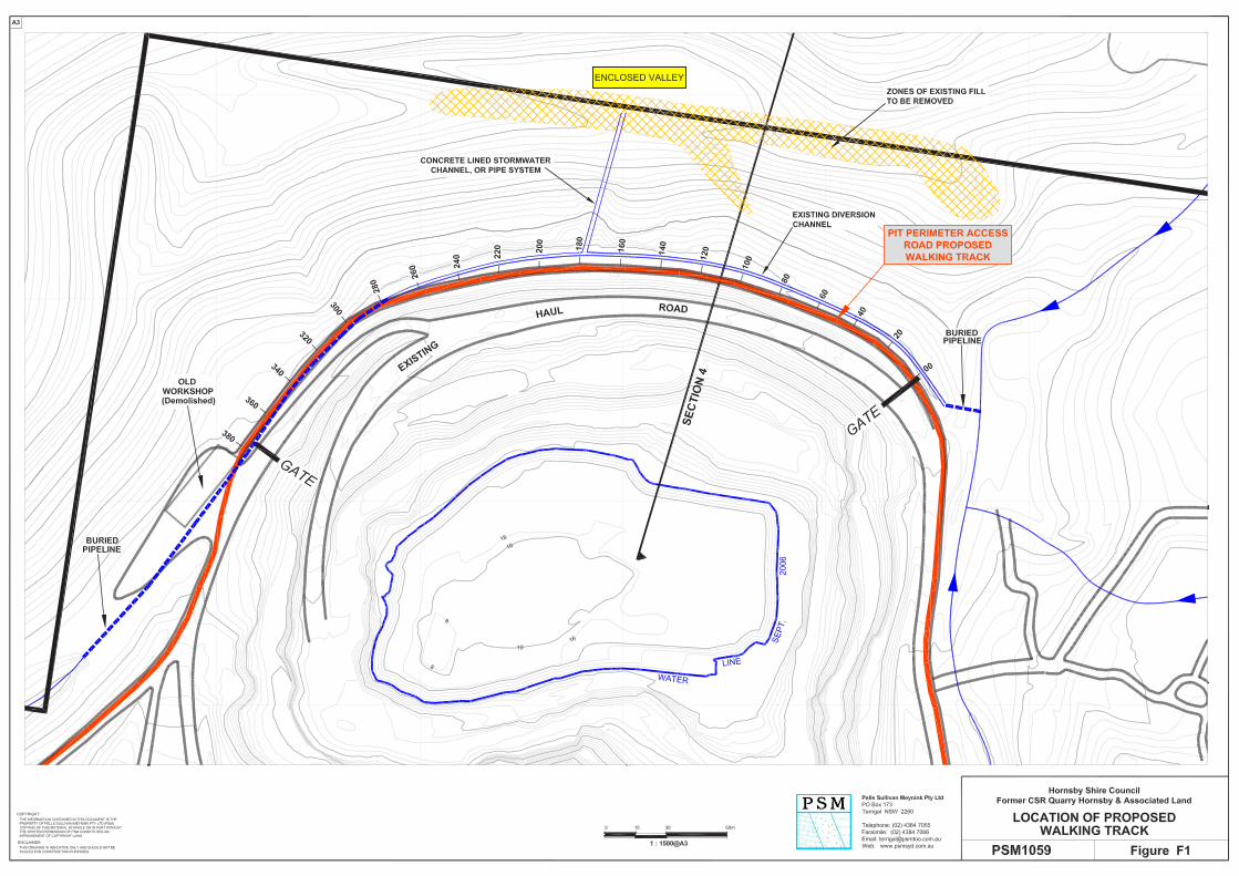
As discussed in the main text of this report, the issue of low factors of safety against deep seated landslips in the north face of the quarry (if the pit is not backfilled) precludes significant developments on or below this north face. However, deep seated landslips in rock masses do not occur suddenly. They would most probably be the result of a rise in groundwater pressures associated with sustained rainfall, and their precursor movements could be picked up by a suitable monitoring system and by observation. The risk of bench scale rockfalls on the north face also means that general public access to this area should not be allowed unless extensive stabilisation measures are implemented. However, consideration could be given to undertaking a focussed scope of stabilisation measures to allow the creation of a public walkway around the north face at about RL 90m. The proposed location of this walkway is shown on Figure F1. It corresponds to the location of the present pit perimeter access track. The extent of the stabilisation measures appropriate for a public walkway is very much a matter of Council’s view in respect to liability issues. It is fair to say that if no works were undertaken the risk to walkers on the track described in this Appendix would be no greater than associated with many walks in the Blue Mountains. For the purpose of this Appendix, PSM have taken the view that in a man-made quarry environment the public may expect a higher level of protection than in, say, a Blue Mountains landscape. Therefore this Appendix sets out works that may be deemed conservative because they are based on achieving a relatively low level of risk consistent with civil engineering works. The walkway could be implemented without any of these works. In preparing this proposal it is assumed that the access would be controlled by Hornsby Council in that it could be closed off if monitoring data, or inspections by Council personnel, indicated that potentially unsafe conditions exist during or following extreme or extended wet periods. F2. LAYOUT AND CONSTRAINTS
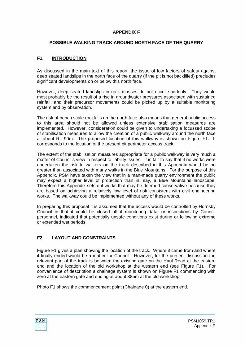
Figure F1 gives a plan showing the location of the track. Where it came from and where it finally ended would be a matter for Council. However, for the present discussion the relevant part of the track is between the existing gate on the Haul Road at the eastern end and the location of the old workshop at the western end (see Figure F1). For convenience of description a chainage system is shown on Figure F1 commencing with zero at the eastern gate and ending at about 385m at the old workshop. Photo F1 shows the commencement point (Chainage 0) at the eastern end.
2
PSM1059.TR1 Appendix F
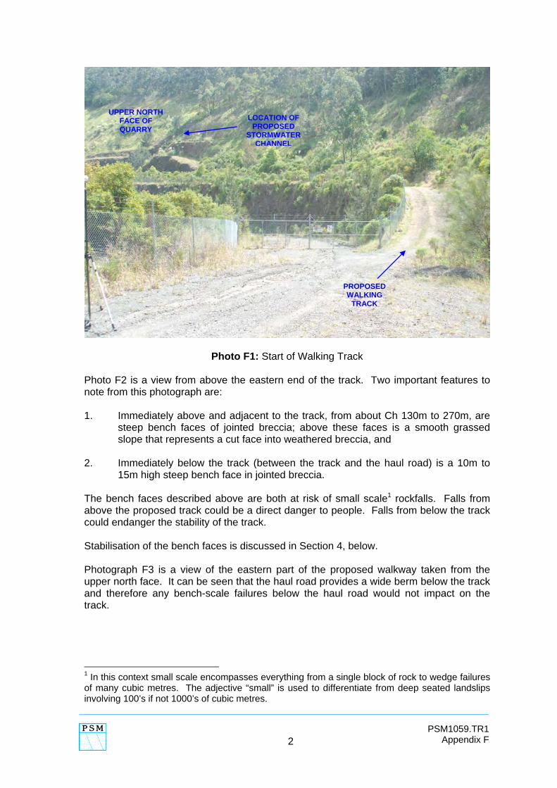
Photo F1: Start of Walking Track Photo F2 is a view from above the eastern end of the track. Two important features to note from this photograph are: 1. Immediately above and adjacent to the track, from about Ch 130m to 270m, are
steep bench faces of jointed breccia; above these faces is a smooth grassed slope that represents a cut face into weathered breccia, and
2. Immediately below the track (between the track and the haul road) is a 10m to
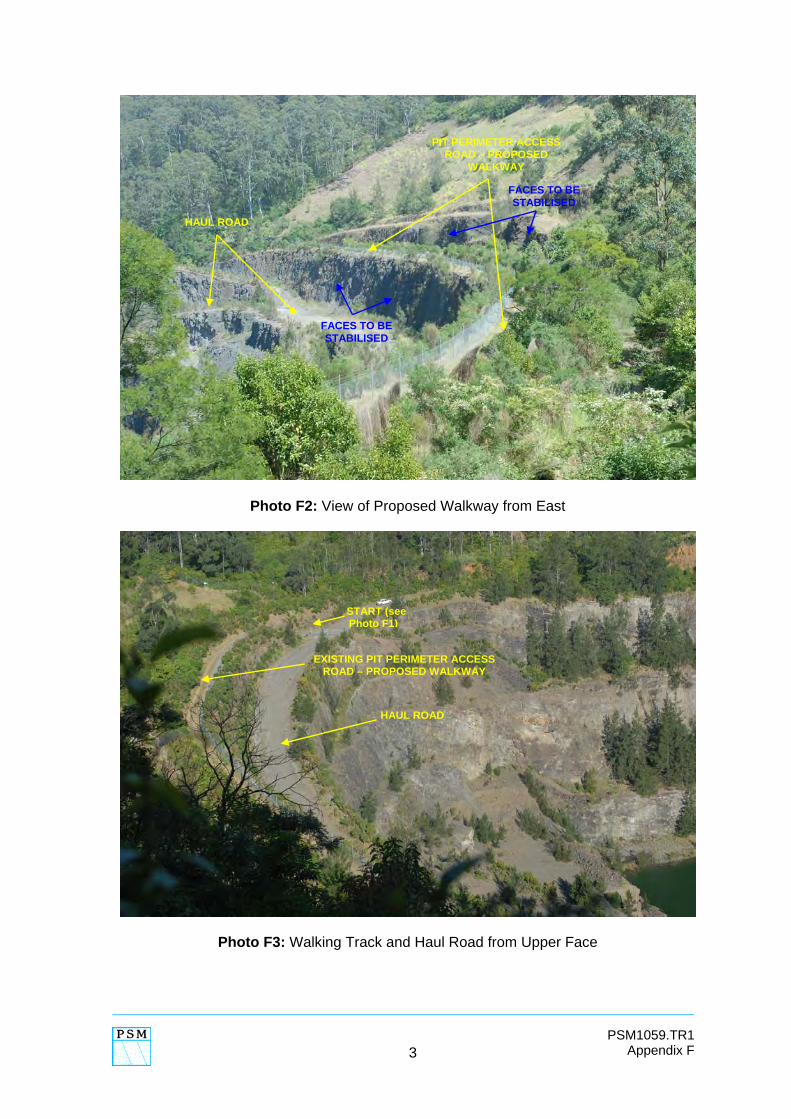
15m high steep bench face in jointed breccia. The bench faces described above are both at risk of small scale1 rockfalls. Falls from above the proposed track could be a direct danger to people. Falls from below the track could endanger the stability of the track. Stabilisation of the bench faces is discussed in Section 4, below. Photograph F3 is a view of the eastern part of the proposed walkway taken from the upper north face. It can be seen that the haul road provides a wide berm below the track and therefore any bench-scale failures below the haul road would not impact on the track.
1 In this context small scale encompasses everything from a single block of rock to wedge failures of many cubic metres. The adjective “small” is used to differentiate from deep seated landslips involving 100’s if not 1000’s of cubic metres.
PROPOSED WALKING
TRACK
UPPER NORTH FACE OF QUARRY
LOCATION OF PROPOSED
STORMWATER CHANNEL
3
PSM1059.TR1 Appendix F
Photo F2: View of Proposed Walkway from East
Photo F3: Walking Track and Haul Road from Upper Face
PIT PERIMETER ACCESS ROAD – PROPOSED
WALKWAY
HAUL ROAD
FACES TO BE STABILISED
FACES TO BE STABILISED
START (see Photo F1)
HAUL ROAD
EXISTING PIT PERIMETER ACCESS ROAD – PROPOSED WALKWAY
4
PSM1059.TR1 Appendix F
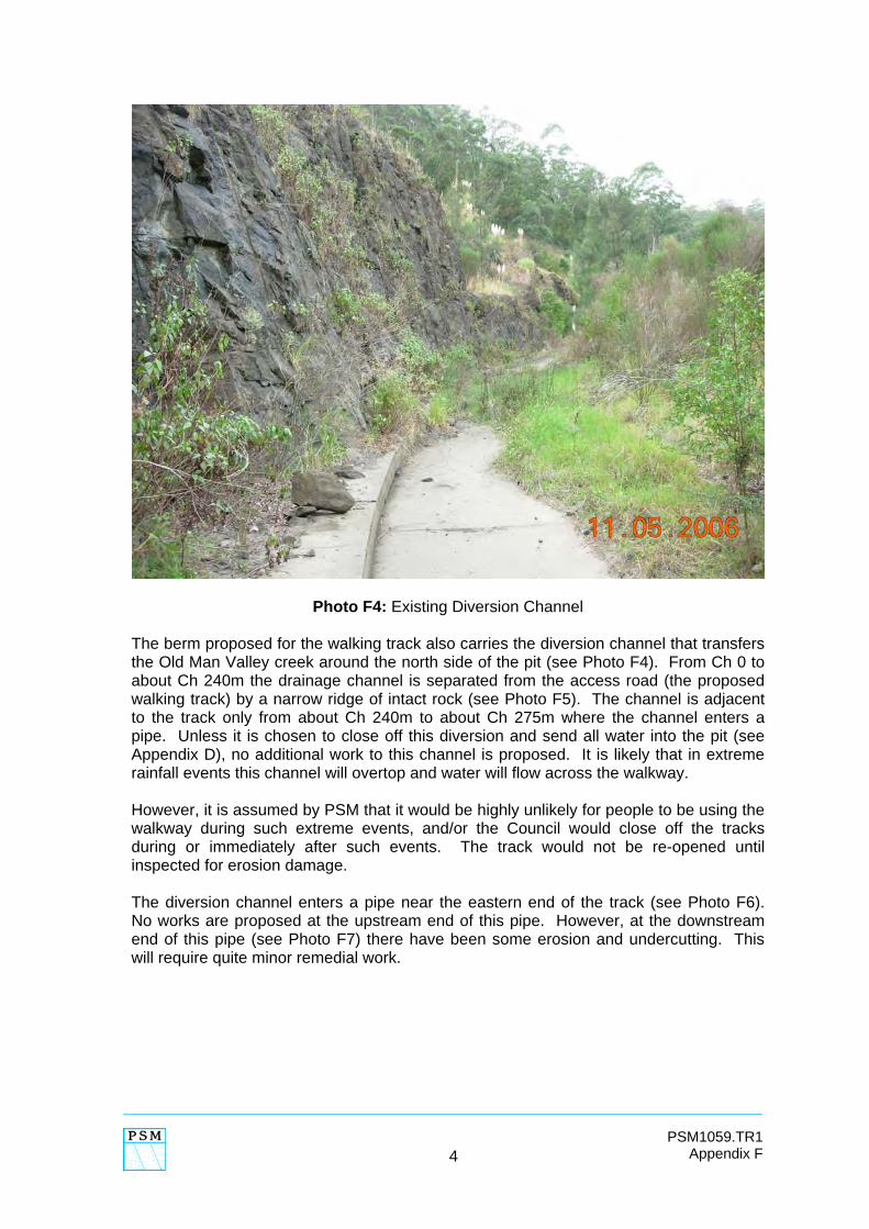
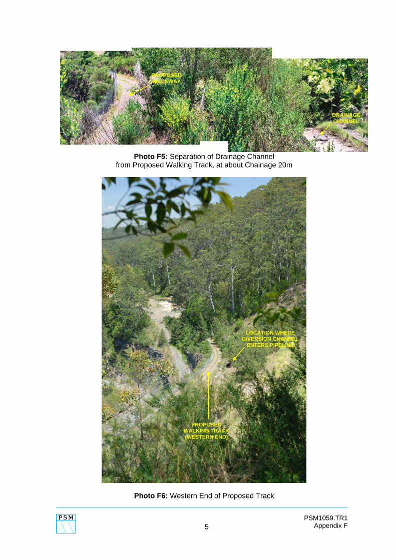
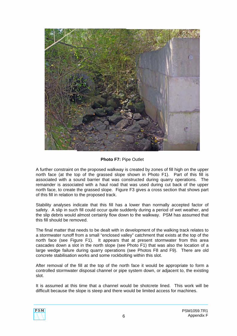
Photo F4: Existing Diversion Channel The berm proposed for the walking track also carries the diversion channel that transfers the Old Man Valley creek around the north side of the pit (see Photo F4). From Ch 0 to about Ch 240m the drainage channel is separated from the access road (the proposed walking track) by a narrow ridge of intact rock (see Photo F5). The channel is adjacent to the track only from about Ch 240m to about Ch 275m where the channel enters a pipe. Unless it is chosen to close off this diversion and send all water into the pit (see Appendix D), no additional work to this channel is proposed. It is likely that in extreme rainfall events this channel will overtop and water will flow across the walkway. However, it is assumed by PSM that it would be highly unlikely for people to be using the walkway during such extreme events, and/or the Council would close off the tracks during or immediately after such events. The track would not be re-opened until inspected for erosion damage. The diversion channel enters a pipe near the eastern end of the track (see Photo F6). No works are proposed at the upstream end of this pipe. However, at the downstream end of this pipe (see Photo F7) there have been some erosion and undercutting. This will require quite minor remedial work.
5
PSM1059.TR1 Appendix F
Photo F5: Separation of Drainage Channel
from Proposed Walking Track, at about Chainage 20m
Photo F6: Western End of Proposed Track
PROPOSED WALKING TRACK (WESTERN END)
LOCATION WHERE DIVERSION CHANNEL
ENTERS PIPELINE
DRAINAGE CHANNEL
PROPOSED WALKWAY
6
PSM1059.TR1 Appendix F
Photo F7: Pipe Outlet
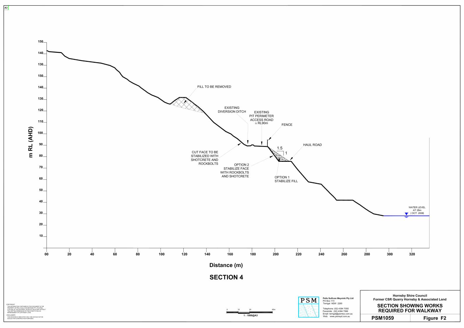
A further constraint on the proposed walkway is created by zones of fill high on the upper north face (at the top of the grassed slope shown in Photo F1). Part of this fill is associated with a sound barrier that was constructed during quarry operations. The remainder is associated with a haul road that was used during cut back of the upper north face, to create the grassed slope. Figure F3 gives a cross section that shows part of this fill in relation to the proposed track. Stability analyses indicate that this fill has a lower than normally accepted factor of safety. A slip in such fill could occur quite suddenly during a period of wet weather, and the slip debris would almost certainly flow down to the walkway. PSM has assumed that this fill should be removed. The final matter that needs to be dealt with in development of the walking track relates to a stormwater runoff from a small “enclosed valley” catchment that exists at the top of the north face (see Figure F1). It appears that at present stormwater from this area cascades down a slot in the north slope (see Photo F1) that was also the location of a large wedge failure during quarry operations (see Photos F8 and F9). There are old concrete stabilisation works and some rockbolting within this slot. After removal of the fill at the top of the north face it would be appropriate to form a controlled stormwater disposal channel or pipe system down, or adjacent to, the existing slot. It is assumed at this time that a channel would be shotcrete lined. This work will be difficult because the slope is steep and there would be limited access for machines.
7
PSM1059.TR1 Appendix F
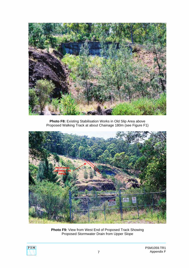
Photo F8: Existing Stabilisation Works in Old Slip Area above Proposed Walking Track at about Chainage 180m (see Figure F1)
Photo F9: View from West End of Proposed Track Showing Proposed Stormwater Drain from Upper Slope
PROPOSED CHANNEL OR
PIPES
8
PSM1059.TR1 Appendix F
F3. SUMMARY OF PROPOSED WORKS TO ALLOW DEVELOPMENT OF THE TRACK
In accordance with the discussion in Section 2, above, the proposed works are:
(1) Stabilise the bench face below the walking track by one of two options (see Figure F2),
• OPTION 1 – place a stabilisation fill along the haul road. • OPTION 2 – stabilise relevant parts using rockbolts and some
shotcrete.
(2) Stabilise bench faces above the track using shotcrete and rockbolts. (3) Remove the fill from the upper part of the north face. (4) Construct a stormwater control structure down the north face. (5) Remediate the pipe outlet erosion protection measures.
In regard to Point (1), Option 1, it is noted that construction of stabilising fill along the haul road would preclude access to the base of the quarry for any future quarry backfilling operations. F4. APPROXIMATE COST ESTIMATES
The following cost estimates are order of magnitude figures for the works set out in Section 3, above. By this is meant that if an estimate is given as $1,000 it is highly unlikely to actually cost $100, or $10,000. Preparation of detailed cost estimates would require development of full designs, including such matters as:
• design of a new haul road to reach the fill areas on the upper north face, • detailed plans of the bench faces showing where all rockbolts and areas
of shotcrete would be located, and • detailed design of the stormwater channel down the north face.
F4.1. Stabilisation of Bench Face Below Walkway
OPTION 1 Figure F2 shows the proposed stabilising fill. The intention of this fill is to prevent bench scale failures (block fallout and wedge slips) that could endanger the walkway. The fill would extend from just beyond the gate (about Ch 20 in Figure F1) to the top of the ramp at about Ch 340 (the ramp can be seen in Photo F2). The total volume of fill is calculated as 30,000m3. This fill could come from elsewhere in the quarry; for examples from the Eastern Zone (Part 2 shown on Drawing PSM1059-3)
9
PSM1059.TR1 Appendix F
or from the South Western Area (Part 4). PSM has adopted a price of $10 per cubic metre for the compacted fill (including contractor establishment) giving a cost estimate of $300,000. OPTION 2 This would comprise stabilisation of the batter face below the walking track with rockbolts and some areas of shotcrete. The total face area between Ch 20m and Ch 340m is about 3,500m2. It is recommended that areas of muddy breccia (see Photos F10 and F11 at about Ch 230m) be covered with polypropylene reinforced shotcrete (nominally 60mm thick) with short glass fibre reinforced (GRP) dowels to pin the shotcrete. Strip drains would be placed at 2m centres behind the shotcrete. Over the remainder of the face stabilisation would be by typically 2.4m long GRP rockbolts specifically targeted to increase the safety factors against block and wedge failures. For cost estimating purposes PSM has adopted $1300/m2 for shotcrete (including stripdrains and dowels) and $450 for nominally 2.4m long GRP rockbolts. It is estimated that about 800m2 of face will require shotcrete (approximately 60m length, 14m high). It is also estimated that about 30% of the total face area will require rockbolting, with bolts at an average spacing of 2m x 2m. Hence the cost estimate is: Shotcrete 800 x 0.06 x 1300 = $62,400
Rockbolts 4
0.3x3500 x 450 = $118,100
TOTAL, say, $180,000 F4.2. Stabilisation of Bench Faces Above Walkway
Some areas of the bench faces immediately above the walkway require stabilisation to safeguard walkers against falling blocks of rock. While the pathway would not be directly below the bench faces it is assumed that there would be nothing preventing walkers from being on the diversion channel (see Photo F4) and therefore directly below the face. The bench faces requiring stabilisation extend from about Ch 125m to Ch 170m and from about Ch 180m to about Ch 280m. The total face area is about 800m2. Some bolting has already been undertaken at about Ch 800m (see Photo F12). This work would be covered with shotcrete.
10
PSM1059.TR1 Appendix F
For costing purposes it is assumed that 40% of the area will be shotcreted (average 60mm thick) in combination with 2m GRP dowels at an average of 2m x 2m and stripdrains at about 2m centres. The cost estimate is based on shotcrete at $1200/m3 and 2m GRP dowels at $400 each. Hence the estimate is:
Shotcrete 0.4 x 800 x 0.06 x $1200 = $23,040
Dowels 0.4 x 4
800 x 400 = $32,000
TOTAL, say, $60,000
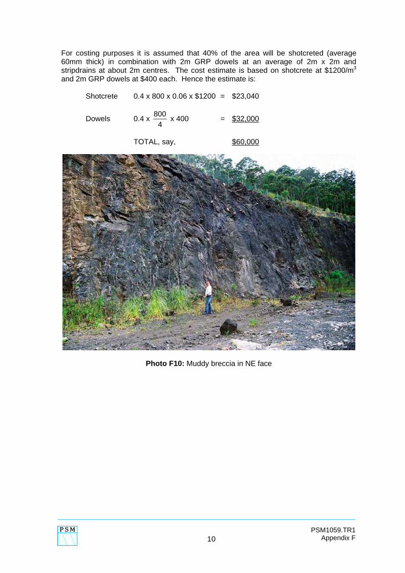
Photo F10: Muddy breccia in NE face
11
PSM1059.TR1 Appendix F
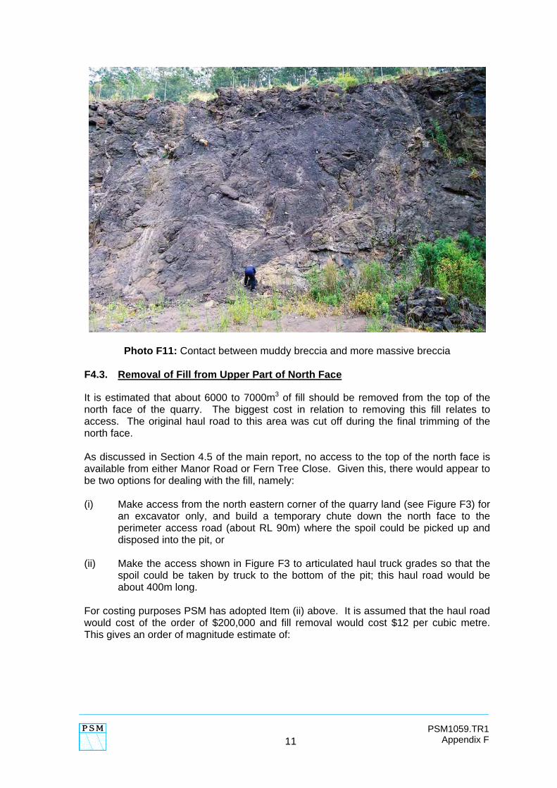
Photo F11: Contact between muddy breccia and more massive breccia F4.3. Removal of Fill from Upper Part of North Face
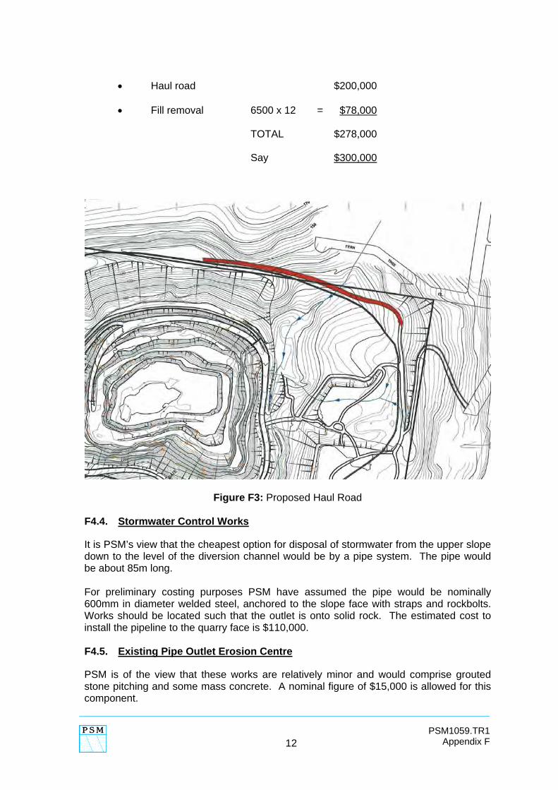
It is estimated that about 6000 to 7000m3 of fill should be removed from the top of the north face of the quarry. The biggest cost in relation to removing this fill relates to access. The original haul road to this area was cut off during the final trimming of the north face. As discussed in Section 4.5 of the main report, no access to the top of the north face is available from either Manor Road or Fern Tree Close. Given this, there would appear to be two options for dealing with the fill, namely: (i) Make access from the north eastern corner of the quarry land (see Figure F3) for
an excavator only, and build a temporary chute down the north face to the perimeter access road (about RL 90m) where the spoil could be picked up and disposed into the pit, or
(ii) Make the access shown in Figure F3 to articulated haul truck grades so that the
spoil could be taken by truck to the bottom of the pit; this haul road would be about 400m long.
For costing purposes PSM has adopted Item (ii) above. It is assumed that the haul road would cost of the order of $200,000 and fill removal would cost $12 per cubic metre. This gives an order of magnitude estimate of:
12
PSM1059.TR1 Appendix F
• Haul road $200,000 • Fill removal 6500 x 12 = $78,000 TOTAL $278,000
Say $300,000
Figure F3: Proposed Haul Road F4.4. Stormwater Control Works
It is PSM’s view that the cheapest option for disposal of stormwater from the upper slope down to the level of the diversion channel would be by a pipe system. The pipe would be about 85m long. For preliminary costing purposes PSM have assumed the pipe would be nominally 600mm in diameter welded steel, anchored to the slope face with straps and rockbolts. Works should be located such that the outlet is onto solid rock. The estimated cost to install the pipeline to the quarry face is $110,000. F4.5. Existing Pipe Outlet Erosion Centre
PSM is of the view that these works are relatively minor and would comprise grouted stone pitching and some mass concrete. A nominal figure of $15,000 is allowed for this component.
13
PSM1059.TR1 Appendix F
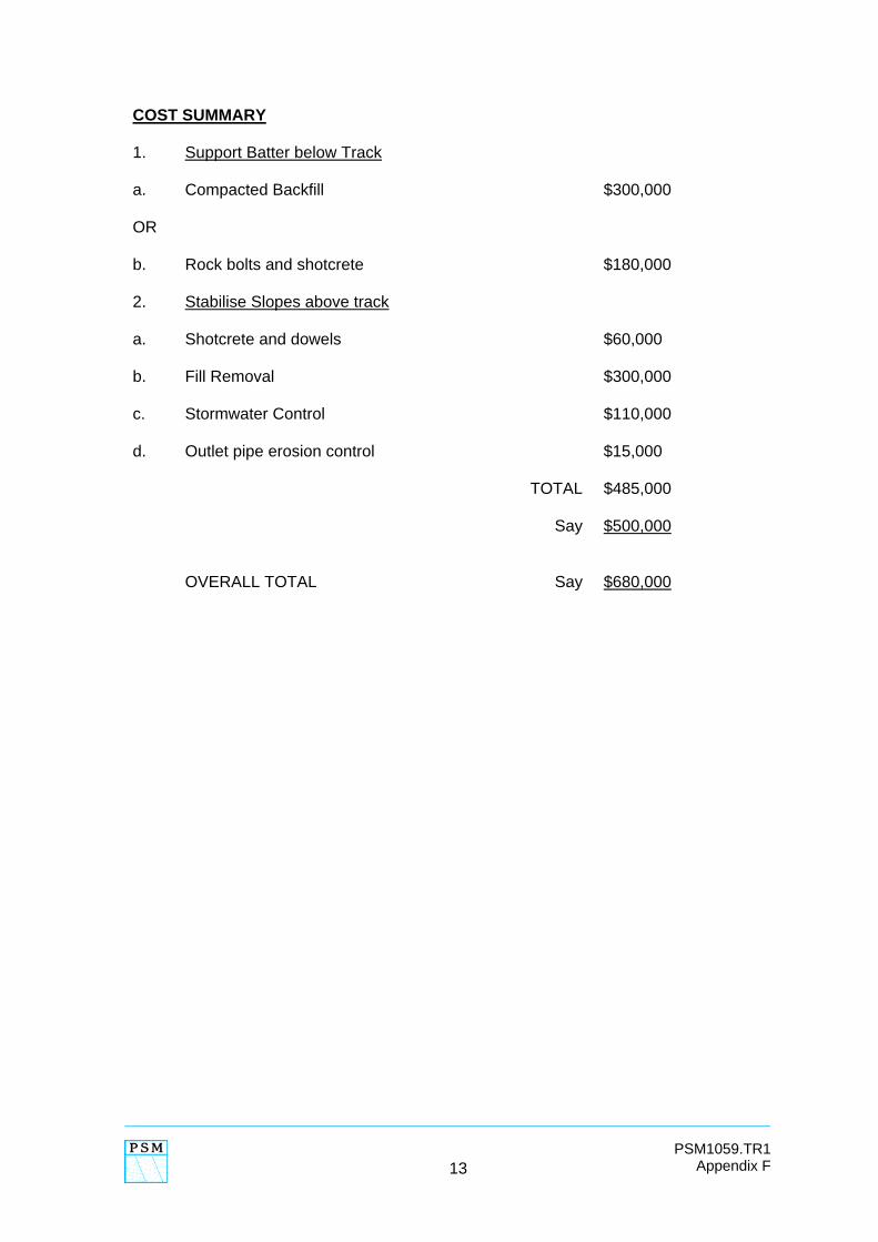
COST SUMMARY 1. Support Batter below Track
a. Compacted Backfill $300,000 OR b. Rock bolts and shotcrete $180,000 2. Stabilise Slopes above track
a. Shotcrete and dowels $60,000 b. Fill Removal $300,000 c. Stormwater Control $110,000 d. Outlet pipe erosion control $15,000 TOTAL $485,000 Say $500,000 OVERALL TOTAL Say $680,000
ENCLOSED VALLEY