Embed Size (px)
Citation preview
NERC | 2021 GADS Data Reporting Instructions | January 2021 E8-1
Appendix E8: Unit Design Data – Combined Cycle Units and Block Design Data (Voluntary Reporting)
Note: The NERC Board of Trustees approved the GADS Task Force Report (dated July 20, 2011)1, which states that design data collection outside the required nine fields is solely voluntary. However, the GADS staff encourages that reporters report and update GADS design data frequently. This action can be completed by sending in this form to [email protected]. GADS staff encourages using the software for design entry and updating.
Instructions Submit the data in this section once during the life of each combined cycle/block unit. If a major change is made to a unit which significantly changes its characteristics, then resubmit this section with updated information. For coded entries, enter a (9) to indicate an alternative other than those specified, and whenever a (9) is entered, write the column number and the answer on the reverse side of the form. When submitting a copy of the original form, make sure that it is legible.
Unit Name
Location of Unit (State)
Energy Information Administration (EIA) Number
Regional Entity
Subregion
Date Reporter
Telephone Number
Date
Here are some definitions used to eliminate some of the ambiguity concerning combined-cycle blocks.
Combined-Cycle Block (referred to here as a “Block”) – By definition, a combined-cycle is a process for generating energy (either electricity or steam) constituted by the marriage of a Brayton Cycle (expand hot gas to turn a gas turbine) with a Rankine Cycle (use heat to boil water to make steam to turn a steam turbine). The combined-cycle block employs electric generating technology that produces electricity from otherwise lost waste heat exiting from one or more gas turbines/jet engines, one or more steam turbines, and balance of plant equipment supporting the production of electricity. In the combined-cycle block, the exiting heat is routed to a conventional boiler or to a heat-recovery steam generator (HRSG) for use by a steam turbine in the production of electricity or steam energy.
There may be more than one block at a plant site. Reporters should complete a form for each individual block.
Units – Each gas turbine/jet engine and each steam turbine is considered a “unit.” Each unit contributes to the total electric generation or steam production of the block. Each unit has its own or shares its generator for providing electric power. They should be considered individual parts of the block.
1 http://www.nerc.com/pa/RAPA/gads/MandatoryGADS/Revised_Final_Draft_GADSTF_Recommendation_Report.pdf
Appendix E8 – Unit Design Data – Combined-Cycle Units and Block Design Data (Voluntary Reporting)
NERC | 2021 GADS Data Reporting Instructions | January 2021 E8-2
Heat Recovery Steam Generator (HRSG) – There may be one or more HRSG or waste heat boilers in a block. Some blocks may have a single HRSG per GT/jet; others may have several GT/jets feeding a single HRSG or any combination thereof. The HRSG does not contribute electricity to the output of the block so is considered a component rather than a “unit.”
Other Balance of Plant Equipment – There is other equipment in the block used to support the production of electricity/heat energy, but they are not related to any specific generating unit and are also considered components. Submit the data in this section once during the life of each block. If a major change is made to a site that significantly changes its characteristics, then resubmit this section with updated information.
General Block Identification 1. Identification
A series of codes uniquely identifies your utility (or company) and the block. NERC assigned a unique code to identify your company. You must assign a unique code that will identify the block being reported. This block code may be any number from 800 to 899. Enter the unique company and block codes and the full name of the entire block below:
Utility (Company) Code: ______________ Block Code: ________________
Name of Block, including site name: _______________________________________________________________________________________
2. Date the Block Entered Service
The in-service date establishes the starting point for review of historical performance of the block. Starting dates of each unit may be different. Supply unit dates at the specified location on this form. Using the criteria described below, report the date the block entered service.
Date (Month/day/year): _______________________________________ Criteria: a) The date the block was first declared available for dispatch at some level of its capability,
OR b) The date the block first operated at 50% of its generator nameplate megawatt capability
(product of the megavolt amperes (MVA) and the rated power factor as stamped on the generator nameplate(s)).
3. Block Loading Characteristics at Time of Design
Enter the number from the list below that best describes the mode of operation for the block as it was originally designed: Loading Characteristic: _________________
1 - Base loaded with minor load following at night and on weekends 2 - Periodic startups with daily load-following and reduced load nightly 3 - Weekly startup with daily load-following and reduced load nightly 4 - Daily startup with daily load-following and taken off-line nightly 5 - Startup chiefly to meet daily peaks 6 – Other, describe: ___________________________________________________________ 7 - Seasonal Operation

Appendix E8 – Unit Design Data – Combined-Cycle Units and Block Design Data (Voluntary Reporting)
NERC | 2021 GADS Data Reporting Instructions | January 2021 E8-3
4. Design and Construction Contractors Identify both the architect/engineer and the general construction contractor responsible for the design and construction of the block. If your company was the principal designer or general constructor, enter “SELF”
Architect/Engineer: __________________________________________________
Constructor: ____________________________________________________________________________ 5. Total Nameplate Rating of all units in the block (in MW)
Enter the TOTAL capability (sum of all gas turbines/jet engines and steam turbines) MW nameplate or published MW rating of the block. In cases where the turbine’s nameplate rating cannot be determined, approximate the rating by multiplying the MVA (megavolt amperes) by the rated power factor found on the nameplate affixed to each unit’s generator (or nameplates in the case of cross compound units).
Total block rating (MW) based on sum of nameplate ratings on all units (in XXXX.X format): __________________________
6. Does the block have co-generation (steam for other than electric generation) capabilities (yes/no)? _____ 7. What is the number of gas turbines/jet engines per Heat Recovery Steam Generator (HRSG)
Identify the number of gas turbines/jet engines feeding exhaust gases into a single HRSG: ___
8. What is the number of gas turbines/jet engines – Heat Recovery Steam Generator (HRSG) Trains Identify the number of sets of gas turbines/jet engines and HRSG trains supplying steam to the steam turbine:
9. Total number of gas turbines/jet engines in block Identify the number of GT/Jets used for generating power:
10. Total number of Heat Recovery Steam Generator (HRSG) in block
Identify the number of HRSG supplying steam to the steam turbine: 11. Total number of Steam Turbines in block
Identify the number of steam turbines receiving steam for generating power: _

Appendix E8 – Unit Design Data – Combined-Cycle Units and Block Design Data (Voluntary Reporting)
NERC | 2021 GADS Data Reporting Instructions | January 2021 E8-4
For each Gas Turbine (GT) or Jet Engine (JE) complete items #12 to #65
(If you have 3 GT, then complete items #12-65 once for each GT.)
Gas Turbine or Jet Engine data 12. Identification
A series of codes uniquely identifies your utility (company), the combined-cycle block and its units. NERC assigned a unique code to identify your company. You must assign the unique code that will identify the GAS TURBINE/JET ENGINE unit being reported. This code may be any number from 300 to 399 or 700-799. Enter the unique company, block and unit code and the full name of each gas turbine/jet engine below:
Utility (Company) Code: _________ Unit Code: ___________ Block Code: _____________ Name of unit: ___________________________________________________________________________
13. Date the gas turbine/jet engine Entered Service
The in-service date establishes the starting point for review of historical performance of each unit. Using the criteria described below, report the date this gas turbine/jet engine entered service.
Date (Month/day/year): _______________________________________
Criteria: a) The date the gas turbine/jet engine was first declared available for dispatch at some level of
its capability, OR b) The date the gas turbine/jet engine first operated at 50% of its generator nameplate
megawatt capability (product of the megavolt amperes (MVA) and the rated power factor as stamped on the generator nameplate(s)).
14. Design and Construction Contractors
Identify both the architect/engineer and the general construction contractor responsible for the design and construction of the unit. If your company was the principal designer or general constructor, enter “SELF”
Architect/Engineer: __________________________________________________ Constructor: __________________________ ________________________________________
15. Gas turbine/jet engine nameplate rating in MW
The nameplate is the design capacity stamped on the gas turbines/jet engines or published on the guarantee flow diagram. In cases where the gas turbine’s nameplate rating cannot be determined, approximate the rating by multiplying the MVA (megavolt amperes) by the rated power factor found on the nameplate affixed to each unit’s generator (or nameplates in the case of cross compound units).
Gas turbine/jet engine rating (MW) (in XXXX.X format): ___________________________ 16. Engine manufacturer – (1) Pratt & Whitney; (2) General Electric; (3) Siemens Westinghouse; (4) Alstom
(ABB); (5) Rolls Royce; (6) Cooper Bessemer; (7) Worthington; (8) Allison; (9) Other, describe ______________________________________________________________________________________
Appendix E8 – Unit Design Data – Combined-Cycle Units and Block Design Data (Voluntary Reporting)
NERC | 2021 GADS Data Reporting Instructions | January 2021 E8-5
BM Biomass OO Oil CC Coal OS Other-Solid (Tons) DI Distillate Oil (No. 2) PC Petroleum Coke GE Geothermal PE Peat GG Gas PR Propane JP JP4 or JP5 SL Sludge Gas KE Kerosene SO Solar LI Lignite WA Water NU Nuclear WD Wood OG Other-Gas (Cu. Ft.) WH Waste Heat OL Other-Liquid (BBL) WM Wind
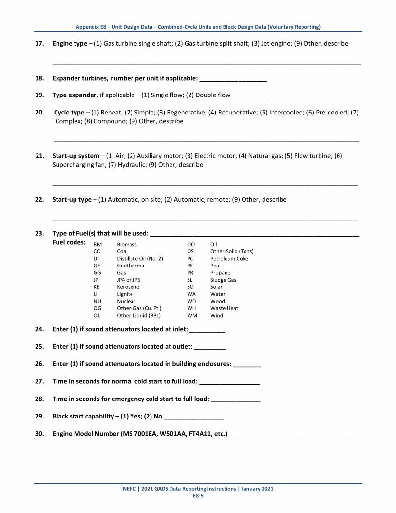
17. Engine type – (1) Gas turbine single shaft; (2) Gas turbine split shaft; (3) Jet engine; (9) Other, describe _______________________________________________________________________________________ 18. Expander turbines, number per unit if applicable: ___________________
19. Type expander, if applicable – (1) Single flow; (2) Double flow _________ 20. Cycle type – (1) Reheat; (2) Simple; (3) Regenerative; (4) Recuperative; (5) Intercooled; (6) Pre-cooled; (7)
Complex; (8) Compound; (9) Other, describe ______________________________________________________________________________________
21. Start-up system – (1) Air; (2) Auxiliary motor; (3) Electric motor; (4) Natural gas; (5) Flow turbine; (6) Supercharging fan; (7) Hydraulic; (9) Other, describe
______________________________________________________________________________________
22. Start-up type – (1) Automatic, on site; (2) Automatic, remote; (9) Other, describe ______________________________________________________________________________________
23. Type of Fuel(s) that will be used: ___________________________________________________________ Fuel codes: 24. Enter (1) if sound attenuators located at inlet: __________ 25. Enter (1) if sound attenuators located at outlet: _________ 26. Enter (1) if sound attenuators located in building enclosures: ________ 27. Time in seconds for normal cold start to full load: _________________ 28. Time in seconds for emergency cold start to full load: ______________ 29. Black start capability – (1) Yes; (2) No _________________ 30. Engine Model Number (MS 7001EA, W501AA, FT4A11, etc.) ____________________________________
Appendix E8 – Unit Design Data – Combined-Cycle Units and Block Design Data (Voluntary Reporting)
NERC | 2021 GADS Data Reporting Instructions | January 2021 E8-6
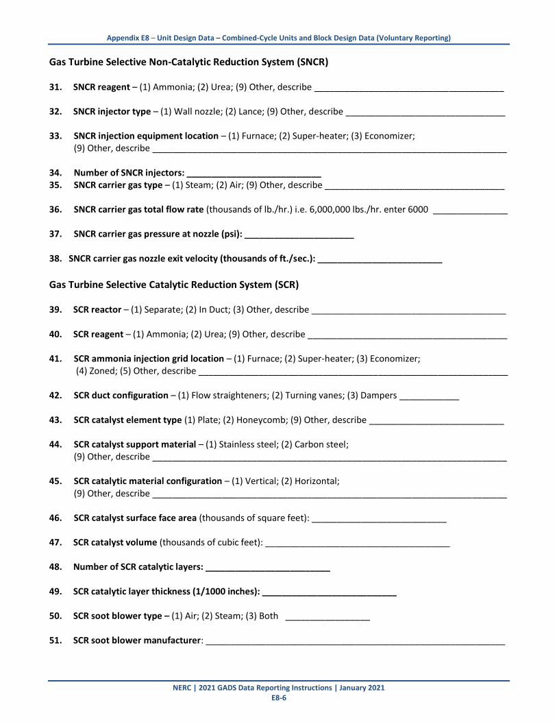
Gas Turbine Selective Non-Catalytic Reduction System (SNCR) 31. SNCR reagent – (1) Ammonia; (2) Urea; (9) Other, describe ______________________________________ 32. SNCR injector type – (1) Wall nozzle; (2) Lance; (9) Other, describe ________________________________ 33. SNCR injection equipment location – (1) Furnace; (2) Super-heater; (3) Economizer; (9) Other, describe _______________________________________________________________________ 34. Number of SNCR injectors: ___________________________ 35. SNCR carrier gas type – (1) Steam; (2) Air; (9) Other, describe ____________________________________ 36. SNCR carrier gas total flow rate (thousands of lb./hr.) i.e. 6,000,000 lbs./hr. enter 6000 _______________ 37. SNCR carrier gas pressure at nozzle (psi): ______________________ 38. SNCR carrier gas nozzle exit velocity (thousands of ft./sec.): _________________________
Gas Turbine Selective Catalytic Reduction System (SCR) 39. SCR reactor – (1) Separate; (2) In Duct; (3) Other, describe _______________________________________ 40. SCR reagent – (1) Ammonia; (2) Urea; (9) Other, describe ________________________________________ 41. SCR ammonia injection grid location – (1) Furnace; (2) Super-heater; (3) Economizer; (4) Zoned; (5) Other, describe ______________________________________________________________
42. SCR duct configuration – (1) Flow straighteners; (2) Turning vanes; (3) Dampers ____________
43. SCR catalyst element type (1) Plate; (2) Honeycomb; (9) Other, describe ___________________________
44. SCR catalyst support material – (1) Stainless steel; (2) Carbon steel; (9) Other, describe _______________________________________________________________________
45. SCR catalytic material configuration – (1) Vertical; (2) Horizontal; (9) Other, describe _______________________________________________________________________
46. SCR catalyst surface face area (thousands of square feet): ___________________________ 47. SCR catalyst volume (thousands of cubic feet): _____________________________________ 48. Number of SCR catalytic layers: _________________________ 49. SCR catalytic layer thickness (1/1000 inches): ___________________________ 50. SCR soot blower type – (1) Air; (2) Steam; (3) Both _________________ 51. SCR soot blower manufacturer: ____________________________________________________________
Appendix E8 – Unit Design Data – Combined-Cycle Units and Block Design Data (Voluntary Reporting)
NERC | 2021 GADS Data Reporting Instructions | January 2021 E8-7
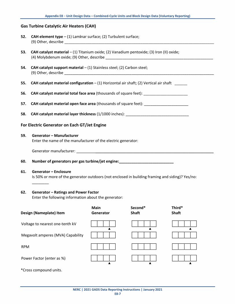
Gas Turbine Catalytic Air Heaters (CAH) 52. CAH element type – (1) Laminar surface; (2) Turbulent surface; (9) Other, describe _______________________________________________________________________ 53. CAH catalyst material – (1) Titanium oxide; (2) Vanadium pentoxide; (3) Iron (II) oxide; (4) Molybdenum oxide; (9) Other, describe ___________________________________________________ 54. CAH catalyst support material – (1) Stainless steel; (2) Carbon steel; (9) Other, describe _______________________________________________________________________ 55. CAH catalyst material configuration – (1) Horizontal air shaft; (2) Vertical air shaft ______ 56. CAH catalyst material total face area (thousands of square feet): _____________________ 57. CAH catalyst material open face area (thousands of square feet): _____________________ 58. CAH catalyst material layer thickness (1/1000 inches): ______________________________
For Electric Generator on Each GT/Jet Engine 59. Generator – Manufacturer Enter the name of the manufacturer of the electric generator:
Generator manufacturer: ________________________________________________________ 60. Number of generators per gas turbine/jet engine:__________________________ 61. Generator – Enclosure
Is 50% or more of the generator outdoors (not enclosed in building framing and siding)? Yes/no: ________
62. Generator – Ratings and Power Factor
Enter the following information about the generator: Main Second* Third* Design (Nameplate) Item Generator Shaft Shaft Voltage to nearest one-tenth kV
▲ ▲ ▲ Megavolt amperes (MVA) Capability
RPM
Power Factor (enter as %)
▲ ▲ ▲
*Cross compound units.
Appendix E8 – Unit Design Data – Combined-Cycle Units and Block Design Data (Voluntary Reporting)
NERC | 2021 GADS Data Reporting Instructions | January 2021 E8-8
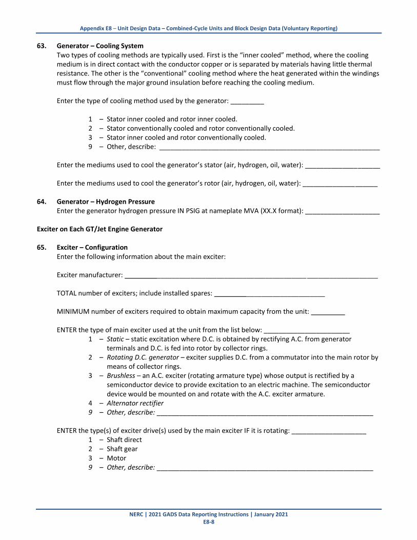
63. Generator – Cooling System Two types of cooling methods are typically used. First is the “inner cooled” method, where the cooling medium is in direct contact with the conductor copper or is separated by materials having little thermal resistance. The other is the “conventional” cooling method where the heat generated within the windings must flow through the major ground insulation before reaching the cooling medium.
Enter the type of cooling method used by the generator: _________
1 – Stator inner cooled and rotor inner cooled. 2 – Stator conventionally cooled and rotor conventionally cooled. 3 – Stator inner cooled and rotor conventionally cooled. 9 – Other, describe: ___________________________________________________________
Enter the mediums used to cool the generator’s stator (air, hydrogen, oil, water): ____________________ Enter the mediums used to cool the generator’s rotor (air, hydrogen, oil, water): ____________________
64. Generator – Hydrogen Pressure Enter the generator hydrogen pressure IN PSIG at nameplate MVA (XX.X format): ____________________
Exciter on Each GT/Jet Engine Generator 65. Exciter – Configuration Enter the following information about the main exciter:
Exciter manufacturer: ________________________________________ ___________________
TOTAL number of exciters; include installed spares: _____________________
MINIMUM number of exciters required to obtain maximum capacity from the unit: ENTER the type of main exciter used at the unit from the list below: _______________________
1 – Static – static excitation where D.C. is obtained by rectifying A.C. from generator terminals and D.C. is fed into rotor by collector rings.
2 – Rotating D.C. generator – exciter supplies D.C. from a commutator into the main rotor by means of collector rings.
3 – Brushless – an A.C. exciter (rotating armature type) whose output is rectified by a semiconductor device to provide excitation to an electric machine. The semiconductor device would be mounted on and rotate with the A.C. exciter armature.
4 – Alternator rectifier 9 – Other, describe: __________________________________________________________
ENTER the type(s) of exciter drive(s) used by the main exciter IF it is rotating: ____________________ 1 – Shaft direct 2 – Shaft gear 3 – Motor
9 – Other, describe: __________________________________________________________

Appendix E8 – Unit Design Data – Combined-Cycle Units and Block Design Data (Voluntary Reporting)
NERC | 2021 GADS Data Reporting Instructions | January 2021 E8-9
For each Heat Recovery Steam Generator (HRSG) Complete items #66 to #87
(If you have 3 HRSGs, then complete items #66-87 once for each HRSG.) 66. Enter the unit code information for each GT/Jet Engine that supplies heat energy to this single HRSG. Utility (Company) Code: _____________ Unit Code “A”: ______________ Block Code:______________
Name of unit “A”, including site name: _______________________________________________________
Utility (Company) Code: _____________ Unit Code “B”: _______________ Block Code:_____________
Name of unit “B”, including site name: _______________________________________________________
Utility (Company) Code: _____________ Unit Code “C”: _______________ Block Code:_____________
Name of unit “C”, including site name: _______________________________________________________
Utility (Company) Code: _____________ Unit Code “D”: _______________ Block Code:_____________
Name of unit “D”, including site name: _______________________________________________________
67. HRSG – Manufacturer
Enter the name of the manufacturer and the model or series name or number of the HRSG:
HRSG manufacturer: _____________________________________________________________________ HRSG model or series name/number: _______________________________________________________
68. HRSG – Enclosure
Is 50% or more of the HRSG outdoors (not enclosed in building framing and siding)? (Y/N):_______
69. HRSG – Nameplate Steam Conditions With Duct Burners Enter the following steam conditions at the full load, valves-wide-open design point at the exit of the HRSG to the steam turbine when the HRSG is experiencing supplemental firing: HIGH-PRESSURE Steam flow rate (in lbs/hr): ______________________ Design temperature (ºF): ______________ Design pressure (psig): __________________________ INTERMEDIATE PRESSURE Steam flow rate (in lbs/hr): ______________________ Design temperature (ºF): ______________

Appendix E8 – Unit Design Data – Combined-Cycle Units and Block Design Data (Voluntary Reporting)
NERC | 2021 GADS Data Reporting Instructions | January 2021 E8-10
Design pressure (psig): __________________________ LOW-PRESSURE Steam flow rate (in lbs/hr): ______________________ Design temperature (ºF): ______________ Design pressure (psig): __________________________ REHEAT PRESSURE Steam flow rate (in lbs/hr): ______________________ Design temperature (ºF): ______________ Design pressure (psig): __________________________
70. HRSG – Nameplate Steam Conditions Without Duct Burners Enter the following steam conditions at the full load, valves-wide-open design point at the exit of the HRSG to the steam turbine when the HRSG is not experiencing supplemental firing: HIGH-PRESSURE Steam flow rate (in lbs/hr): ______________________ Design temperature (ºF): ______________ Design pressure (psig): __________________________ INTERMEDIATE PRESSURE Steam flow rate (in lbs/hr): ______________________ Design temperature (ºF): ______________ Design pressure (psig): __________________________ LOW-PRESSURE Steam flow rate (in lb/hr): ______________________ Design temperature (ºF): ______________ Design pressure (psig): __________________________ REHEAT PRESSURE Steam flow rate (in lb/hr): ______________________ Design temperature (ºF): ______________ Design pressure (psig): __________________________
Appendix E8 – Unit Design Data – Combined-Cycle Units and Block Design Data (Voluntary Reporting)
NERC | 2021 GADS Data Reporting Instructions | January 2021 E8-11
71. Is the HRSG top-supported (pressure parts hang like in a utility boiler) or bottom-supported? ______________________
72. Does the HRSG have vertical or horizontal heat exchangers? ________________
73. Is the duct insulation cold casing (insulation on the inside of the duct) or hot casing (insulation on the
outside of the duct)? ___________________________ 74. HRSG Supplemental Firing (duct burners) Does the HRSG have the capability of supplemental firing (duct firing) (y/n)?_____ Is the HRSG supplemental used “normally, as needed” or only in extreme emergency? ______________________________ 75. HRSG bypass capabilities Does the HRSG have bypass capability? (y/n) _______________ 76. Does the HRSG have a drum or is it a once-through design? ___________________ 77. HRSG – Circulation System
Enter the following information on the pumps used to recirculate water through the HRSG:
HRSG recirculation pump(s) manufacturer(s): ______________________________________________________________________________________ TOTAL number of HRSG recirculation pumps; include installed spares: MINIMUM number of HRSG recirculation pumps required to obtain maximum capacity from this HRSG: Enter the type of HRSG recirculation pump(s) at the block:
1 – Injection (or injection seal) – controlled-leakage HRSG recirculation pumps mounted
vertically with a rigid shaft designed to carry its own thrust. 2 – Leakless (or canned, canned-motor, or zero-leakage) – pump and its motor are an integral
pressurized and sealed component. 9 – Other, describe: ___________________________________________________________ 78. HRSG – Duct-Burner System (General)
Enter the following information on the duct burner systems installed for use by this HRSG:
Duct fuel burner(s) manufacturer(s): _____________________________________________________________________________
TOTAL number of duct fuel burners: ________

Appendix E8 – Unit Design Data – Combined-Cycle Units and Block Design Data (Voluntary Reporting)
NERC | 2021 GADS Data Reporting Instructions | January 2021 E8-12
79. HRSG – Duct-Burner Management System Enter the name of the manufacturer of each of the following burner management systems:
Manufacturer of the combustion control system that coordinates the feedwater, air, and fuel subsystems for continuous HRSG operation:
___________________________________________________ __________________________ Manufacturer of the burner management system that monitors only the fuel and air mixture during all phases of operation to prevent the formation of an explosive mixture: ____________________ _________________________________________________________
80. Auxiliary Systems – Feedwater (HRSG Feed) Pumps
The feedwater (HRSG feed) pumps move the feedwater through the feedwater system into the HRSG. Enter the following information on the feedwater pumps installed at this HRSG:
Feedwater (HRSG feed) pump(s) manufacturer(s): _____________________________________________________________________________
Normal operating speed (RPM) of the feedwater pumps:
TOTAL number of feedwater pumps. Include installed spares:
MINIMUM number of feedwater pumps required to obtain maximum capacity from the HRSG: PERCENT (%) of the HRSG’s maximum capacity that can be achieved with a single feedwater pump (XXX.X format): __________________
81. Auxiliary Systems – Feedwater (HRSG Feed) Pump Drives Manufacturer(s) of motor(s) or steam turbine(s) that drives the feedwater pump(s). _____________________________________________________________________________
Enter the type of equipment used to drive the feedwater (HRSG feed) pumps: ___________
1 – Motor – single speed 6 – Motor gear 2 – Motor – two speed 7 – Steam gear 3 – Motor – variable speed 8 – Shaft gear 4 – Steam turbine 9 – Other, describe 5 – Shaft Specify coupling type used for feedwater (HRSG feed) pump: ___________
1 – Hydraulic 2 – Mechanical 9 – Other, describe: ___________________________________________________________
Appendix E8 – Unit Design Data – Combined-Cycle Units and Block Design Data (Voluntary Reporting)
NERC | 2021 GADS Data Reporting Instructions | January 2021 E8-13
82. Auxiliary Systems – Start-up Feedwater (HRSG Feed) Pumps
Start-up feedwater pump(s) manufacturer(s): ________________________________________ _____________________________________
Manufacturer(s) of the motor(s) that drives the start-up feedwater pump(s): _______________ ______________________________________________________________ PERCENT (%) of the HRSG’s maximum capacity that can be achieved with a single Start-up feedwater pump (XXX.X format): _______________
Indicate the additional capabilities of the start-up feedwater pump: ____________
1 – ADDITIVE: operated in conjunction with the feedwater (HRSG feed) pumps. 2 – REPLACEMENT: can carry load when the feedwater pumps are inoperative. 3 – START-UP only: cannot be used in lieu of the feedwater pumps. 9 – Other, describe: ___________________________________________________________
83. Auxiliary Systems – High-pressure Feedwater Heaters High-pressure feedwater heaters are those heat exchangers between the feedwater (HRSG feed) pumps discharge and the economizer inlet. Enter the following information for the High-pressure feedwater heaters for this HRSG:
High-pressure feedwater heater(s) manufacturer(s): _____________________________________________________________________________
TOTAL number of high-pressure feedwater heaters:
Feedwater heater tube materials used in 50% or more of the tubes: ______________________
Enter the type of high-pressure feedwater heater(s): ________________ 1 – Horizontal – longitudinal axis of the heater shell is horizontal.
2 – Vertical – longitudinal axis of the heater shell is vertical. 3 – Both 9 – Other, describe: __________________________________________________________

Appendix E8 – Unit Design Data – Combined-Cycle Units and Block Design Data (Voluntary Reporting)
NERC | 2021 GADS Data Reporting Instructions | January 2021 E8-14
84. Auxiliary Systems – Intermediate Pressure Feedwater Heaters Intermediate-pressure feedwater heaters are those heat exchangers between the condensate booster pump discharge and the deaerator. Enter the following information for the intermediate pressure feedwater heaters for this HRSG:
Intermediate-pressure feedwater heater(s) manufacturer(s): _____________________________________________________________________________
TOTAL number of intermediate-pressure feedwater heaters:
Feedwater heater tube materials used in 50% or more of the tubes: Enter the type of INTERMEDIATE pressure feedwater heater(s): _____________
1 – Horizontal – longitudinal axis of the heater shell is horizontal. 2 – Vertical – longitudinal axis of the heater shell is vertical. 3 – Both 9 – Other, describe: __________________________________________________________
85. Auxiliary Systems – Low-Pressure Feedwater Heaters
Low-pressure feedwater heaters are those heat exchangers between the condensate pump discharge and the condensate booster pump inlet. If the HRSG does not have condensate booster pumps, the low-pressure feedwater heaters are located between the condensate pumps and the deaerator. Enter the following information for the Low-pressure feedwater heaters for this HRSG:
Low-pressure feedwater heater(s) manufacturer(s): _____________________________________________________________________________
TOTAL number of low-pressure feedwater heaters:
Feedwater heater tube materials used in 50% or more of the tubes: Enter the type of Low-pressure feedwater heater(s): _____________
1 – Horizontal – longitudinal axis of the heater shell is horizontal. 2 – Vertical – longitudinal axis of the heater shell is vertical. 3 – Both 9 – Other, describe: __________________________________________________________
86. Auxiliary Systems – Deaerator Heater Deaerator manufacturer(s): _____________________________________________________________________________________
Appendix E8 – Unit Design Data – Combined-Cycle Units and Block Design Data (Voluntary Reporting)
NERC | 2021 GADS Data Reporting Instructions | January 2021 E8-15
Enter the type of deaerator heater(s): _____________ 1 – Spray – high-velocity stream jet atomizes and scrubs the condensate. 2 – Tray – series of trays over which the condensate passes and is deaerated. 3 – Vacuum – a vacuum condition inside the shell for deaeration. 4 – Combination
9 – Other, describe: __________________________________________________________ 87. Auxiliary Systems – Heater Drain Pumps
Heater drain pump(s) manufacturer(s): _____________________________________________________________________________
Manufacturer(s) of the motor(s) that drives the heater drain pump(s): ____________________ _________________________________________________________

Appendix E8 – Unit Design Data – Combined-Cycle Units and Block Design Data (Voluntary Reporting)
NERC | 2021 GADS Data Reporting Instructions | January 2021 E8-16
For each Steam Turbine (ST) Complete items #88 to #104 (If you have 3 ST, then complete items #88-104 once for each ST.) 88. Identification
A series of codes uniquely identifies your company and generating units. NERC assigned a unique code to identify your company. You must assign the unique code that will identify the STEAM TURBINE unit being reported. This code may be any number from 100 to 199 or 600-649. Enter the unique company, block and generating-unit code and the full name of each steam turbine below:
Company Code: ________________ Unit Code: _________________ Block Code:______________
Name of unit, including site name: ______________________________________________________________________________________
89. Does the steam turbine have bypass capability? (y/n) _________ 90. Steam Turbine – Manufacturer Enter the name of the manufacturer of the steam turbine:
Steam turbine manufacturer: ______________________________________________________________________________________
91. Steam Turbine – Enclosure
Is 50% or more of the steam turbine outdoors (not enclosed in building framing and siding)? (Y/N) ________
92. Steam Turbine – Nameplate Rating in MW
Nameplate is the design capacity stamped on the steam turbine’s nameplate or published on the turbine guarantee flow diagram. In cases where the steam turbine’s nameplate rating cannot be determined, approximate the rating by multiplying the MVA (megavolt amperes) by the rated power factor found on the nameplate affixed to the unit’s generator (or nameplates in the case of cross compound units). Steam turbine’s nameplate rating (MW) (in XXXX.X format): _____________
93. Steam Turbine – Type of Steam Turbine
Identify the steam turbine’s casing or shaft arrangement. Enter the type of steam turbine at the unit: ____________
1 – Single casing – single (simple) turbine having one pressure casing (cylinder). 2 – Tandem compound – two or more casings coupled together in line. 3 – Cross compound – two cross-connected single casing or tandem compound turbine sets
where the shafts are not in line. 4 – Triple compound – three cross-connected single casing or tandem compound turbine
sets. 9 – Other, describe: ___________________________________________________________
Appendix E8 – Unit Design Data – Combined-Cycle Units and Block Design Data (Voluntary Reporting)
NERC | 2021 GADS Data Reporting Instructions | January 2021 E8-17
94. Steam Turbine – Manufacturer’s Building Block or Design Codes Steam turbine building blocks or manufacturer’s design codes are assigned by the manufacturer to designate a series of turbine designs, LM5000 or W501 for example. Enter the following information: Manufacturer’s code, first shaft: ________________________ Manufacturer’s code, second shaft (cross or triple compound units): __________________________ Turbine configuration and number of exhaust flows (e.g., tandem compound, four flow): ______________
95. Steam Turbine – Steam Conditions Enter the following information on the Main, First Reheat, and Second Reheat Steam design conditions: Main steam: Temperature (ºF): ____________ Pressure (psig): ______________
First reheat steam: Temperature (ºF): ____________ Pressure (psig): ______________
Second reheat steam: Temperature (ºF): ____________ Pressure (psig): ______________
96. Steam Turbine – High, Intermediate, and Low-pressure Sections
Enter the following information describing various sections of the steam turbine: High-Pressure Casings TOTAL number of high pressure casings, cylinders or shells: ___________
Back pressure of the high pressure condenser (if applicable) to the nearest one-tenth inch of mercury at the nameplate capacity and design water temperature. (XX.X format): ____________
Combined High-pressure/Intermediate Pressure Casings TOTAL number of high/intermediate-pressure casings, cylinders or shells: __________________ Intermediate Pressure Casings TOTAL number of intermediate-pressure casings, cylinders or shells: _______________ Combined Intermediate/Low-pressure Casings TOTAL number of intermediate/low-pressure casings, cylinders or shells: __________________ Low-pressure Casings TOTAL number of low-pressure casings, cylinders or shells: ___________________
Back pressure of the low pressure condenser to the nearest one-tenth inch of mercury at nameplate capacity and design water temperature. (XX.X format): ______________
The last stage blade length (inches) of the low-pressure turbine, measured from hub to end of top of blade. (XX.X format): _______________________
Appendix E8 – Unit Design Data – Combined-Cycle Units and Block Design Data (Voluntary Reporting)
NERC | 2021 GADS Data Reporting Instructions | January 2021 E8-18
97. Steam Turbine – Governing System Enter the following information for the steam turbine governing system: Enter the type of governing system used at the unit: _____________
1 – Partial arc – main steam flow is restricted to one sector of the turbine’s first stage at
start-up. 2 – Full arc – main steam is admitted to all sectors of the turbine’s first stage at start-up. 3 – Either – capable of admitting steam using either partial or full arc techniques.
9 – Other, describe: ___________________________________________________________ Enter the type of turbine governing system used at the unit: ____________
1 – Mechanical hydraulic control (MHC) – turbine speed monitored and adjusted through
mechanical and hydraulic linkages. 2 – Analog electro-hydraulic control (EHC) – analog signals control electro-hydraulic linkages
to monitor and adjust turbine speed. 3 – Digital electro-hydraulic control (DHC) – same as EHC except signals are digital rather than
analog. 9 – Other, describe: ___________________________________________________________ 98. Steam Turbine – Lube Oil System Enter the following information for the steam turbine main lube oil system:
Main lube oil system manufacturer: ______________________________________________________________________________________
Main lube oil pump(s) manufacturer: ______________________________________________________________________________________
Manufacturer of the motor(s)/steam turbine(s) that drives the main lube oil pump(s): ______________________________________________________________________________________ TOTAL number of steam turbine main lube oil pumps; include installed spares:
Enter the type of driver on the main lube oil pump: _________________ 1 – Motor 2 – Shaft 3 – Steam turbine 9 – Other, describe: ___________________________________________________________

Appendix E8 – Unit Design Data – Combined-Cycle Units and Block Design Data (Voluntary Reporting)
NERC | 2021 GADS Data Reporting Instructions | January 2021 E8-19
FOR ELECTRIC GENERATOR ON A STEAM TURBINE 99. Generator – Manufacturer Enter the name of the manufacturer of the electric generator:
Generator manufacturer: ______________________________________________________________________________________
100. Generator – Enclosure
Is 50% or more of the generator outdoors (not enclosed in building framing and siding)? (Y/N) __________
101. Generator – Ratings and Power Factor Enter the following information about the generator:
Main Second* Third* Design (Nameplate) Item Generator Shaft Shaft Voltage to nearest one-tenth kV
▲ ▲ ▲ Megavolt amperes (MVA) Capability
RPM
Power Factor (enter as %)
▲ ▲ ▲
*Cross compound units.
102. Generator – Cooling System Two types of cooling methods are typically used. First is the “inner cooled” method, where the cooling medium is in direct contact with the conductor copper or is separated by materials having little thermal resistance. The other is the “conventional” cooling method where the heat generated within the windings must flow through the major ground insulation before reaching the cooling medium.
Enter the type of cooling method used by the generator: ______________
1 – Stator inner cooled and rotor inner cooled. 2 – Stator conventionally cooled and rotor conventionally cooled. 3 – Stator inner cooled and rotor conventionally cooled. 9 – Other, describe
Enter the mediums used to cool the generator’s stator (air, hydrogen, oil, water): ______________ Enter the mediums used to cool the generator’s rotor (air, hydrogen, oil, water): _______________
103. Generator – Hydrogen Pressure Enter the generator hydrogen pressure in PSIG at nameplate MVA (XX.X format): _____________
Appendix E8 – Unit Design Data – Combined-Cycle Units and Block Design Data (Voluntary Reporting)
NERC | 2021 GADS Data Reporting Instructions | January 2021 E8-20
Exciter for Each Steam Turbine Generator
104. Exciter – Configuration Enter the following information about the main exciter:
Exciter manufacturer: ____________________________________________________________________
TOTAL number of exciters. Include installed spares:
MINIMUM number of exciters required to obtain maximum capacity from the unit: Enter the type of main exciter used at the unit:
1 – Static – static excitation where D.C. is obtained by rectifying A.C. from generator terminals and D.C. is fed into rotor by collector rings.
2 – Rotating D.C. generator – exciter supplies D.C. from a commutator into the main rotor by means of collector rings.
3 – Brushless – an A.C. exciter (rotating armature type) whose output is rectified by a semiconductor device to provide excitation to an electric machine. The semiconductor device would be mounted on and rotate with the A.C. exciter armature.
4 – Alternator rectifier 9 – Other, describe: ___________________________________________________________
Enter the type(s) of exciter drive(s) used by the main exciter IF it is rotating: 1 – Shaft direct 2 – Shaft gear 3 – Motor
9 – Other, describe: ___________________________________________________________

Appendix E8 – Unit Design Data – Combined-Cycle Units and Block Design Data (Voluntary Reporting)
NERC | 2021 GADS Data Reporting Instructions | January 2021 E8-21
Auxiliary Systems 105. Auxiliary Systems – Main Condenser Enter the following information for the main condenser and its auxiliaries:
Main condenser manufacturer: ______________________________________________________________________________________ Type of condenser (water, air): __________________________
TOTAL number of passes made by the circulating water as it passes through the condenser: ___ TOTAL number of condenser shells: _______
Condenser tube materials used in the majority (50% or more) of the condenser tubes: _______ Air ejector(s) or vacuum pump(s) manufacturer: ______________________________________________________________________________________ Enter the type of air-removal equipment used on the condenser: _______________
1 – Vacuum pump 2 – Steam jet air ejector 3 – Both
9 – Other, describe: ___________________________________________________________ Enter the type of cooling water used in the condenser: _______________
1 – Fresh – salinity values less than 0.50 parts per thousand. 2 – Brackish – salinity values ranging from approximately 0.50 to 17 parts per thousand. 3 – Salt – salinity values greater than 17 parts per thousand. 9 – Other, describe: ___________________________________________________________
Enter the origin of the circulating water used in the condenser: ________________
1 – River
2 – Lake 3 – Ocean or Bay 4 – Cooling Tower
9 – Other, describe: ___________________________________________________________
Appendix E8 – Unit Design Data – Combined-Cycle Units and Block Design Data (Voluntary Reporting)
NERC | 2021 GADS Data Reporting Instructions | January 2021 E8-22
106. Auxiliary Systems – Condenser Cleaning System Enter the following information about the ON-LINE main condenser cleaning system (leave blank if cleaning is manual):
On-line main condenser cleaning system manufacturer: ______________________________________________________________________________________ Enter the type of on-line main condenser cleaning system used at the unit: _________________________
1 – Ball sponge rubber 2 – Brushes 9 – Other, describe: ___________________________________________________________ 107. Auxiliary Systems – Condensate Polishing System
A “condensate polisher” is an in-line demineralizer located in the condensate water system to treat water coming from the condenser to the HRSG. It is not the demineralizer that prepares raw or untreated water for eventual use in the steam production process.
Enter the following information about the condensate polishing system at the unit:
Condensate polishing system manufacture: ______________________________________________________________________________________ Enter the % of the condensate flow at maximum unit capacity that can be treated (XX.X format): __________________
108. Auxiliary Systems – Condensate Pumps Enter the following information for the main condensate pumps (those at the discharge of the condenser):
Condensate pump(s) manufacturer(s): ______________________________________________________________________________________
Manufacturer(s) of the motor(s) that drives the condensate pump(s): ______________________________________________________________________________________
TOTAL number of condensate pumps. Include installed spares: ___
MINIMUM number of condensate pumps required to obtain maximum capacity from the block: ________
Appendix E8 – Unit Design Data – Combined-Cycle Units and Block Design Data (Voluntary Reporting)
NERC | 2021 GADS Data Reporting Instructions | January 2021 E8-23
109. Auxiliary Systems – Condensate Booster Pumps Condensate booster pumps increase the pressure of the condensate water between the low-pressure and the intermediate or high-pressure feedwater heaters. Enter the following information for the condensate booster pumps:
Condensate booster pump(s) manufacturer(s): ______________________________________________________________________________________
Manufacturer(s) of the motor(s) that drives the condensate booster pump(s): ______________________________________________________________________________________ TOTAL number of condensate booster pumps; include installed spares: ___ MINIMUM number of condensate booster pumps required for maximum capacity from the block: ______
110. Auxiliary Systems – Circulating Water Pumps Enter the following information for the circulating water pumps:
Circulating water pump(s) manufacturer(s): ______________________________________________________________________________________
Manufacturer(s) of the motor(s) that drives the circulating water pump(s): ______________________________________________________________________________________ TOTAL number of circulating water pumps; include installed spares: __
MINIMUM number of circulating water pumps required to obtain maximum capacity from the block DURING WINTER SEASON.
111. Auxiliary Systems – Cooling Tower and Auxiliaries Enter the following information for the cooling towers and all related auxiliary equipment at the block:
Cooling tower manufacturer(s): ______________________________________________________________________________________
Cooling tower fan(s) manufacturer(s): ______________________________________________________________________________________
Manufacturer(s) of the motor(s) that drives the cooling tower fan(s): ______________________________________________________________________________________
Appendix E8 – Unit Design Data – Combined-Cycle Units and Block Design Data (Voluntary Reporting)
NERC | 2021 GADS Data Reporting Instructions | January 2021 E8-24
Enter the type of cooling tower(s) used: _____________
1 – Mechanical draft (induced, forced, cross-flow and counter-flow) – fan(s) used to move ambient air through the tower.
2 – Atmospheric spray – air movement is dependent on atmospheric conditions and the aspirating effect of the spray nozzles.
3 – Hyperbolic (natural draft) – temperature difference between condenser circulating water and ambient air conditions, aided by hyperbolic tower shape, creates natural draft of air through the tower to cool the water.
4 – Deck-filled – wetted surfaces such as tiers of splash bars or decks aid in the breakup and retention of water drops to increase the evaporation rate.
5 – Coil shed – a combination structure of a cooling tower installed over a substructure that houses atmospheric coils or sections.
9 – Other, describe: ___________________________________________________________
The cooling tower booster pumps increase the pressure of the circulating water and force the water to the top of the cooling tower.
Cooling tower booster pump(s) manufacturer(s): ______________________________________________________________________________________ Manufacturer(s) of the motor(s) that drives the cooling tower booster pump(s): ______________________________________________________________________________________ TOTAL number of cooling tower booster pumps; include installed spares: ___ MINIMUM number of cooling tower booster pumps required to obtain maximum capacity from the block:
Appendix E8 – Unit Design Data – Combined-Cycle Units and Block Design Data (Voluntary Reporting)
NERC | 2021 GADS Data Reporting Instructions | January 2021 E8-25
Balance of Plant
112. Balance of Plant – Main Transformer The main transformer is the block step-up transformer connecting the generator (or multiple generators if block is cross compound) to the transmission system. Enter the following information for the MAIN transformer(s) at the block:
Main transformer(s) manufacturer(s): ______________________________________________________________________________________
TOTAL number of main transformers; include installed spares:
Megavolt ampere (MVA) size of the main transformer(s):
HIGH SIDE voltage in kilovolts (kV) of the main transformer(s) at 55 ºF: Enter the type of MAIN transformer at the block: __________
1 – Single phase 2 – Three phase 9 – Other, describe: ___________________________________________________________
113. Balance of Plant – Block Auxiliary Transformer The block auxiliary transformer supplies the auxiliaries when the block is synchronized. Enter the following information for this transformer: Block auxiliary transformer(s) manufacturer(s): ______________________________________________________________________________________
TOTAL number of block auxiliary transformer(s):
LOW SIDE voltage in kilovolts (kV) of the block auxiliary transformer(s) at 55 ºF:
114. Balance of Plant – Station Service Transformer
The station service (start-up) transformer supplies power from a station high-voltage bus to the station auxiliaries and also to the block auxiliaries during block start-up and shutdown. It also may be used when the block auxiliary transformer is not available or nonexistent.
Station service transformer(s) manufacturer(s): ______________________________________________________________________________________
TOTAL number of station service transformer(s):
HIGH SIDE voltage in kilovolts (kV) of the station service transformer(s) at 55 ºF: LOW SIDE voltage in kilovolts (kV) of the station service transformer(s) at 55 ºF: