Embed Size (px)
Citation preview

APPENDIX E GROUNDWATER MONITORING PLAN MODEL AIRPLANE FIELD LIMITED PURPOSE LANDFILL APPLICATION PORT GAMBLE
Prepared for Pope Resources, LP/OPG Properties, LLC
Prepared by Anchor QEA, LLC
720 Olive Way, Suite 1900
Seattle, Washington 98101
March 2017 Revision

Appendix E: Groundwater Monitoring Plan March 2017 Revision Model Airplane Field Limited Purpose Landfill Application i 160388-02.01 Port Gamble
TABLE OF CONTENTS 1 INTRODUCTION ................................................................................................................ 1
2 GROUNDWATER MONITORING SYSTEM DESIGN ....................................................... 2
3 SAMPLING AND ANALYSIS PLAN ................................................................................... 4
3.1 Schedule ............................................................................................................................4
3.2 Project Management and Responsibilities ......................................................................4
3.3 Groundwater Sampling and Design ................................................................................5
3.4 Monitoring Well Installation Methods ...........................................................................5
3.4.1 Monitoring Well Development .................................................................................7
3.4.1.1 Development Criteria ....................................................................................... 9
3.4.1.2 Development Documentation........................................................................ 10
3.4.2 Investigation Derived Waste Management.............................................................10
3.5 Monitoring Well Sampling ............................................................................................11
3.5.1 Sampling Methods ....................................................................................................11
3.5.2 Sample Nomenclature ..............................................................................................13
3.5.3 Sample Handling Procedures ...................................................................................14
3.5.3.1 Sample Custody Procedures ........................................................................... 14
3.5.3.2 Sample Shipping and Receipt Requirements ................................................ 15
3.6 Chemical Analytical Testing .........................................................................................16
4 MONITORING AND INSPECTION REPORT .................................................................. 19
5 REFERENCES .................................................................................................................... 21
List of Figures Figure 1 Proposed Monitoring Well Locations
List of Attachments Attachment 1 Quality Assurance Project Plan

Appendix E: Groundwater Monitoring Plan March 2017 Revision Model Airplane Field Limited Purpose Landfill Application ii 160388-02.01 Port Gamble
LIST OF ACRONYMS AND ABBREVIATIONS °C degrees centigrade
BGS below ground surface
COC chain of custody
DO Dissolved oxygen
DQO Data Quality Objective
Ecology Washington State Department of Ecology
FC Field Coordinator
HASP Health and Safety Plan
HDPE high density polyethylene
Landfill Limited Purpose Landfill
LOD limit of detection
LOQ limit of quantitation
MDL Method Detection Limit
Mill Site Pope & Talbot Sawmill Site
MAF Model Airplane Field Site
ORP oxidation reduction potential
PR/OPG Pope Resources, LP/Olympic Property Group, LLC
PVC polyvinyl chloride
QA quality assurance
QAPP Quality Assurance Project Plan
QC quality control
SAP Sampling and Analysis Plan
SVOC semivolatile organic compound
WAC Washington Administrative Code

Appendix E: Groundwater Monitoring Plan March 2017 Revision Model Airplane Field Limited Purpose Landfill Application 1 160388-02.01 Port Gamble
1 INTRODUCTION
The Port Gamble Bay sediment cleanup project will involve dredging and excavation of up to approximately 150,000 cubic yards of sediment (referred to as dredged material) adjacent to the former Pope & Talbot Sawmill Site (Mill Site). Excavation and dredging of approximately 110,000 cy of material from Port Gamble Bay has occurred as of December, 2016. An additional 40,000 cy Mill Site habitat restoration project soils will be excavated prior to 2021. Consistent with cleanup project permits and approvals, dredged material is being placed in temporary containment areas on the Mill Site uplands for sparging (i.e., rinsing out seawater), stockpiling, and profiling prior to final placement and/or disposal. Following confirmation that saltwater has been successfully sparged from dredged sediments, some or all of these materials, along with similar Mill Site habitat restoration project soils meeting suitability criteria, may be placed in a Limited Purpose Landfill (Landfill) at the Port Gamble Model Airplane Field Site (MAF). All work is being performed by Pope Resources, LP/Olympic Property Group, LLC (PR/OPG) and their contractors. The MAF is located west of State Route 104 in Port Gamble at approximately 47°50’52”N and 122°35’14”W. The maximum extent of the project is shown on Figure 3, and will be confined to parcel identification/account numbers 072702-1-018-2004, 072702-1-015-2007, 072702-1-016-2006, and 072702-1-017-2005, owned by PR/OPG. Township is 27N, Range is 2E, and Section is 7. The hydrogeological setting of the MAF is described in Appendix B, and the dredge material and leachate characteristics are described in Appendix C. This appendix uses the information from those two appendices to develop a long-term groundwater monitoring plan for the Landfill. This appendix meets the requirements of groundwater system design and groundwater sampling and analysis plans consistent with Washington Administrative Code (WAC) 173-350-400(4) and WAC 173-350-500.

Appendix E: Groundwater Monitoring Plan March 2017 Revision Model Airplane Field Limited Purpose Landfill Application 2 160388-02.01 Port Gamble
2 GROUNDWATER MONITORING SYSTEM DESIGN
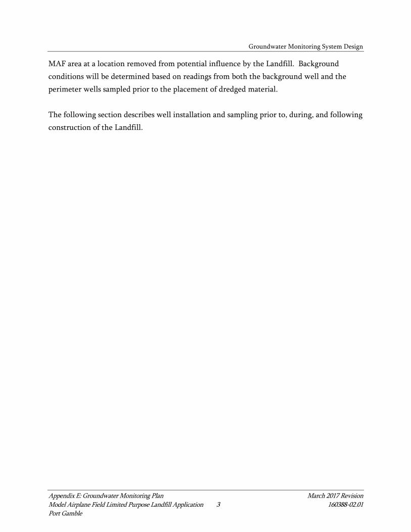
Appendix B describes two flow pathways for infiltrating groundwater from the Landfill: vertical transport through 180 feet of Vashon till and Lawton clay confining units to the underlying regional aquifer, and lateral transport of shallow perched groundwater within the shallow topsoil, fill, or weathered till units. Because of the confining nature of the Vashon till and Lawton clay units, leachate from sediment and soil materials to be placed at the MAF will not reach the underlying Sea-level aquifer for more than 4,000 years. Because chemicals are transported more slowly than water as a result of attenuation characteristics, the relatively low levels of chemicals present in leachate from sediment and soil materials to be placed at the MAF will not reach the underlying Sea-level aquifer for more than 40,000 years. Because of these extremely long transport times, this monitoring system design targets shallow perched groundwater in the shallow topsoil, fill, or weathered till units. The shallow topsoil, fill, or weathered till units are described on Appendix B. The topsoil/ fill unit extends from ground surface to 3 to 7.5 feet below ground surface (BGS) at the MAF, depending on the location. The weathered till unit subsequently extends from the base of the topsoil/fill unit to 8 to 20 feet BGS depending on the location. Potential lateral flow of leachate and perched water along the interface between shallow fill and weathered Vashon till is determined by the gradients of the contacts between these units and by the structure of the sand layers within the shallow till units. Within the proposed Landfill footprint, lateral flow along the top of the Vashon till travels radially, with primary directionality toward the south and east, away from the wetlands to the north, due to the topographic gradients of the MAF. Figure 1 presents the proposed groundwater monitoring well locations. The Landfill is generally on a topographic high; therefore, four monitoring wells are oriented on all sides of the Landfill, providing coverage of potential transport in all directions of the MAF. During installation, the groundwater monitoring wells will be screened in the shallowest observation of perched groundwater. In the absence of observed perched groundwater or water-bearing units, wells will be screened approximately at the interface of the weathered till and the till units. None of the four groundwater wells will be situated upgradient from the Landfill; therefore, one local background monitoring well will also be installed in the
Groundwater Monitoring System Design
Appendix E: Groundwater Monitoring Plan March 2017 Revision Model Airplane Field Limited Purpose Landfill Application 3 160388-02.01 Port Gamble
MAF area at a location removed from potential influence by the Landfill. Background conditions will be determined based on readings from both the background well and the perimeter wells sampled prior to the placement of dredged material. The following section describes well installation and sampling prior to, during, and following construction of the Landfill.
Appendix E: Groundwater Monitoring Plan March 2017 Revision Model Airplane Field Limited Purpose Landfill Application 4 160388-02.01 Port Gamble
3 SAMPLING AND ANALYSIS PLAN
This section constitutes the Sampling and Analysis Plan (SAP) for identification of the sampling and analysis protocols, sample location and frequency, equipment, sample handling, and analytical procedures for implementing groundwater monitoring. This section meets the requirements of WAC 173-350-500(4). Field work will consist of installation of five groundwater monitoring wells and groundwater sampling and analysis prior to, during, and after Landfill construction. A Quality Assurance Project Plan (QAPP) is provided in Attachment 1. A Health and Safety Plan (HASP) will be developed to support the work.
3.1 Schedule
Wells will be installed following preliminary acceptance of the Landfill design approach from Kitsap Public Health. Five new wells will be installed. Baseline sampling will occur in two quarterly events in winter and spring of 2017. Quarterly sampling will continue through construction and post-closure. During construction or post-closure, if monitoring results indicate that the wells have stabilized, then a reduced monitoring frequency may be performed and/or a reduced number of chemicals may be analyzed, if approved by Kitsap Public Health. Beginning in year 10 post-closure, if two or more consecutive monitoring events confirm that the Landfill is not effecting perched groundwater quality, further monitoring can be safely discontinued. A request for a modification in the Post-closure Plan will be made to Kitsap Public Health.
3.2 Project Management and Responsibilities
This section describes the overall project management strategy for implementing and reporting for the SAP. All work is being performed by PR/OPG and their contractors. Project Management and Field Coordination will be performed by Anchor QEA. The Field Coordinator (FC) from Anchor QEA will provide overall direction for the field sampling effort in terms of logistics, personnel assignments, and field operations. The FC will supervise field collection of all samples. The FC will also be responsible for positioning

Sampling and Analysis Plan
Appendix E: Groundwater Monitoring Plan March 2017 Revision Model Airplane Field Limited Purpose Landfill Application 5 160388-02.01 Port Gamble
samples accurately; recording sample locations, depths, and identification; ensuring conformance to sampling and handling requirements, including field decontamination procedures; physical evaluation and logging of samples; and completing chain-of-custody (COC) forms. Sampling and analysis will be completed with equipment owned or contracted by Anchor QEA. All subconsultants will follow the protocols established in this SAP. Anchor QEA will be responsible for the submittal of environmental samples to the designated laboratories for chemical and physical analyses. The Laboratory Project Manager at each laboratory will provide analytical support and will be responsible for providing certified, pre-cleaned sample containers and sample preservatives (as appropriate) and for ensuring that all chemical analyses meet the project Data Quality Objectives (DQOs) and other quality specifications of the QAPP (Attachment 1).
3.3 Groundwater Sampling and Design
Groundwater sampling will be performed using low-flow methodology as described in Section 3.5.1. Field measurements will include temperature, pH, dissolved oxygen (DO), oxidation reduction potential (ORP), turbidity, and conductivity. Laboratory analyses will include total and dissolved metals (13 priority pollutant and barium), semivolatile organic compounds (SVOCs), dioxins/furans, total dissolved solids, total suspended solids, alkalinity, ammonia, and chloride. Samples for dissolved metals analysis will not be field filtered, however, extra precaution will be taken so that the suspended solids are not sampled. For example, if wells are significantly drawn down during purging, then additional time will be taken to allow wells to recharge prior to drawing a sample. Groundwater samples will be immediately submitted for analytical testing.
3.4 Monitoring Well Installation Methods
Anchor QEA will provide a licensed Washington State geologist to direct monitoring well installation. Five 2-inch-diameter polyvinyl chloride (PVC) monitoring wells will be

Sampling and Analysis Plan
Appendix E: Groundwater Monitoring Plan March 2017 Revision Model Airplane Field Limited Purpose Landfill Application 6 160388-02.01 Port Gamble
installed using standard hollow stem auger procedures (four perimeter wells and one background well). The installations will conform to Washington State Department of Ecology (Ecology) specifications. Wells will be logged by a geologist and screened across the shallowest observed perched groundwater at the location, as determined by the field geologist. In absence of perched groundwater, the wells will be screened across the geological contact between weathered till and till. All monitoring wells will be completed with 0.01-slot 2-inch-diameter Schedule 40 PVC screen with a flush-threaded bottom cap no longer than 6 inches long. Blank Schedule 40 PVC casing will extend from the top of the screen to approximately 0.5 foot below ground for flush-mounted wells and extend to no more than 2.5 feet above ground for stick-up wells. A sand pack equivalent to 10/20 silica sand will be placed in the bottom of the bore hole to 2 feet above the top of the screen in all monitoring wells. The monitoring well will be surged prior to placement of the bentonite seal to prevent bridging and facilitate settling of the sand pack. A bentonite seal consisting of bentonite chips will be placed directly on the sand pack to a depth of approximately 1.5 feet below grade or less. The depth to the top of the sand pack and the bentonite will be tagged with a weighted tape to ensure well completion materials are installed to the correct depth. Neat cement grout extending from the top of the bentonite seal ground surface will then be placed on top of the bentonite seal. The neat cement grout shall consist of Portland cement types I, II, or III with 5 percent by dry weight of bentonite. The grout will be emplaced by pumping the grout through a tremie pipe inserted through the augers. The tremie pipe will remain within 5 feet of the grout in the annulus, and the pipe will be withdrawn as the grout level rises. A centralizer will be placed at the bottom and every 20 feet on the deep well. The top of the PVC will be fitted with a standard lockable well plug. Above-ground well completions will consist of a protective steel casing placed around the PVC and extending from at least 6 inches above the PVC to at least 2 feet below ground. A 2-foot-diameter surface cement pad extending to a depth of 2 feet will be placed around the

Sampling and Analysis Plan
Appendix E: Groundwater Monitoring Plan March 2017 Revision Model Airplane Field Limited Purpose Landfill Application 7 160388-02.01 Port Gamble
steel casing. Three metal posts at least 3 inches in diameter will be placed in a triangular arrangement around the casing and cement pad. The posts will extend from a minimum of 3 feet below ground to a minimum of 3 feet above ground. The well shall be labeled permanently and clearly with a well identification. The drilling subcontractor will perform decontamination of all drilling equipment prior to moving to the next monitoring well installation. Water generated from decontamination procedures will be contained in 55-gallon drums and disposed at an off-site facility.
3.4.1 Monitoring Well Development
Following installation of monitoring wells, well development will be used to restore, to the extent possible, the natural hydraulic conditions around each well. A variety of techniques are available for developing wells to ensure turbidity-free groundwater samples. The specific method of well development will be decided upon in the field based on the most current available information. The primary requirement of an effective development technique is to provide reversals or surges in flow to prevent bridging by formation particles, a common problem when flow is always in one direction. Reversals or surges can be created using surge blocks, bailers, pumps, getting tools, or a combination of devices. The common methods for developing wells are described by Aller et al. (1989) and Driscoll (1986) and include:
• Overpumping • Backwashing • Surging • Bailing • Jetting • Airlift pumping • Air surging

Sampling and Analysis Plan
Appendix E: Groundwater Monitoring Plan March 2017 Revision Model Airplane Field Limited Purpose Landfill Application 8 160388-02.01 Port Gamble
Recommended monitoring well development methods include pumping, overpumping, bailing, and backwashing, in combination with some form of surging. The most effective combination and timing of these methods must be determined through field testing or from experience developing wells in similar hydrogeologic regimes. In general, formation water should be used for development. However, it may be necessary to introduce water from an outside source if yields are not sufficient to use formation water. The introduced water must be tested for chemical properties to evaluate its potential impact on the in situ water quality (USEPA 1986). Well development procedures that have the potential to alter groundwater quality should not be used. Therefore, methods that involve adding water or other fluids to the well, or that use air to accomplish development, are not recommended. Generally unsuitable methods for monitoring well development include jetting, airlift pumping, and air surging. However, air development techniques may be used if they offer site-specific advantages over other methods and extreme care is taken to prevent air from contacting the screened interval. Air development techniques must only be implemented by an experienced operator. Movement of groundwater into the well in one direction generally results in bridging of the particles. A means of inducing flow reversal is necessary to break down the bridging and produce a stable filter. Aller et al. (1989) state that one of the most effective and efficient methods to induce flow reversal is the careful use of a properly constructed surge block. For a more detailed description of proper usage of a surge block and other methods of achieving flow reversal, see the Handbook of Suggested Practices for the Design and Installation of Ground-water Monitoring Wells: Technology Support Center, Environmental Monitoring Systems Laboratory (Aller et al. 1989). One example of a well development field protocol uses the following procedure:
1. Record static water level and total well depth. 2. Set the pump and record pumping rate and turbidity. Pump until turbidity reaches
desired level or stabilizes. 3. Discontinue pumping and surge the well.

Sampling and Analysis Plan
Appendix E: Groundwater Monitoring Plan March 2017 Revision Model Airplane Field Limited Purpose Landfill Application 9 160388-02.01 Port Gamble
4. Measure depth to the bottom of the well. If more than 10 percent of the screen is occluded by sediments, remove excess sediment by bailing.
5. Reset the pump, recording pumping rate and turbidity. Pump until turbidity reaches desired level or stabilizes. If the well has been properly designed, the amount of pumping required to achieve the desired turbidity level will be substantially less than required in the first pumping cycle.
6. Repeat surging and pumping until the well yields water of acceptable turbidity at the beginning of a pumping cycle. A good way to ensure that development is complete is to shut the pump off during the last anticipated pumping cycle, leaving the pump in place, and restarting it sometime later. The turbidity of the discharge water should remain low.
The pumping rate used during development must be greater than the highest rate expected to be used during subsequent purging and sampling. In fact, recent field experience suggests that extremely low (i.e., 100 to 500 milliliters per minute) purging and sampling pumping rates may significantly reduce the turbidity of groundwater samples (Puls et al. 1990). The pump intake should be placed close to, or within, the well screen interval.
3.4.1.1 Development Criteria
Development should continue until clear, artifact-free, formation water is produced. Water quality parameters such as specific conductance, pH, temperature, and turbidity should be measured during development and should stabilize before development is stopped. Turbidity measurements are the most critical development criteria. Other parameters should be used to provide supplemental information regarding aquifer conditions. Stabilization of these parameters is indicative of the presence of formation water. If water was added during well construction or development, two to three times the volume of water added must be removed. Finally, the well should be producing visually clear water before development is stopped. After development is completed, wells should be allowed to stabilize and re-equilibrate before sampling. The time necessary for stabilization depends on the characteristics of the aquifer and the geochemistry of the parameters to be modified. Generally, high-permeability

Sampling and Analysis Plan
Appendix E: Groundwater Monitoring Plan March 2017 Revision Model Airplane Field Limited Purpose Landfill Application 10 160388-02.01 Port Gamble
formations require less time (i.e., several days) than low-permeability formations (i.e., several weeks).
3.4.1.2 Development Documentation
Monitoring well development must be thoroughly documented to verify that foreign materials have been removed, formation water is being sampled, and turbidity has reached acceptable levels or stabilized. The following data should be recorded before and during well development:
1. Date and duration of development. 2. Water level from the marked measuring point on the top of casing before and
24 hours after well development. 3. Depth from top of well casing to the top of any sediment present in the well before,
during, and after sampling. 4. Types and quantity of drilling fluids introduced during drilling and development. 5. Field measurements (e.g., turbidity, specific conductance, pH, DO, temperature)
taken before, during, and after well development. 6. Volume and physical characteristics of developed water (e.g., odor, color, clarity, and
particulate matter). 7. Type and capacity of pump and/or bailer used and pumping rates. 8. Detailed description of all development methods used.
3.4.2 Investigation Derived Waste Management
All soil cuttings obtained from drilling activities will be disposed of in 55-gallon drums and consolidated. Purge water from groundwater wells will be collected in 55-gallon drums or other suitable containers selected by the FC. After well installation, the 55-gallon drums will be transported for appropriate disposal. All disposable sampling materials and personal protective equipment used in sample processing, such as disposable coveralls, gloves, and paper towels, will be placed in heavy-duty garbage bags or other appropriate containers. Disposable supplies will be placed in a normal refuse container for disposal as solid waste.
Sampling and Analysis Plan
Appendix E: Groundwater Monitoring Plan March 2017 Revision Model Airplane Field Limited Purpose Landfill Application 11 160388-02.01 Port Gamble
3.5 Monitoring Well Sampling
3.5.1 Sampling Methods
Groundwater sampling methods used at the Site are designed to obtain samples as representative of in situ groundwater quality as possible. Anchor QEA will collect groundwater level measurements and groundwater samples from the installed wells no sooner than 24 hours after development. Groundwater samples from monitoring wells will be collected using a peristaltic pump with dedicated polyethylene tubing at each well location and in accordance with low-flow groundwater purging and sampling methodology. Another pump may be used as necessary if a peristaltic pump does not provide sufficient flow at the required head. The monitoring wells will be measured and sampled using the following procedure:
1. Don the required personal protective equipment as defined in the HASP. 2. Ensure that the sampling area is visible to operational activities and communicate
with Site personnel. 3. Check the well for any damage or evidence of tampering and record the observations
on the field data sheet. 4. Unlock and open the well monument and remove the well cap. 5. Measure and record the depth to water and record the measurement on the field data
sheet. Measure water level from reference point to the nearest 0.01 foot. 6. Attach and secure the polyethylene tubing to the peristaltic pump. Lower the tubing
slowly into the well. Set the end of the tubing at approximate middle of the well screen. Be careful not to place the end of the tubing on the bottom of the well because this may disturb any sediment present in the bottom of the well.
7. Start pumping the well by selecting the lowest pump speed. Ideally, the pump rate should equal the well recharge rate with little or no water level drawdown in the well (drawdown shall be 0.3 foot or less).
8. During purging, the ultimate low-flow rate should be from 0.1 to 0.5 liter per minute. Measure the pumping rate using a graduated cylinder and stopwatch or similar device. Record the pumping rate and depth to water on the field data sheet or in the logbook.

Sampling and Analysis Plan
Appendix E: Groundwater Monitoring Plan March 2017 Revision Model Airplane Field Limited Purpose Landfill Application 12 160388-02.01 Port Gamble
9. During purging, monitor the field parameters (temperature, pH, turbidity, ORP, conductivity, and DO) approximately every 3 to 5 minutes. A flow-through cell or similar will be used to monitor the field parameters. Begin measuring field parameters after the flow-through cell has been “flushed” with purged groundwater twice.
10. The well is considered stabilized and ready for sample collection when the indicator parameters have stabilized for three consecutive readings, as follows:
− ±0.1 for pH − ±3 percent for conductivity − ±10 percent for DO − ±10 percent for turbidity − ±10 mV for ORP
11. The tubing must not be removed from the well between purging and sampling. 12. If the recharge rate of the well is very low, do not purge the well dry. The water
level in the well should stay above the level of the tubing inlet to prevent air entrainment. If air bubbles are observed in the purge stream, lower the flow rate. If air bubbles are still observed, turn off the pump and allow the well to recover before sampling.
13. Once the field parameters have stabilized, collect the samples directly from the end of the tubing. Volatiles and analyses that degrade by aeration must be collected first. The bottles should be preserved and filled according to the procedures specified in the QAPP.
14. Fill all sample bottles by allowing the pump discharge to flow gently down the inside of the bottle with minimal turbulence. Cap each bottle as it is filled. For polycyclic aromatic hydrocarbons, fill each 1-liter amber bottle to nearly the top and cap thereafter. Samples collected for dissolved metals analysis will not be field-filtered during collection, however, extra precaution will be taken so that the suspended solids are not sampled. For example, if wells are significantly drawn down during purging, then additional time will be taken to allow wells to recharge prior to drawing a sample. Fill one 500-milliliter high density polyethylene (HDPE) bottle to nearly the top and cap thereafter.
Sampling and Analysis Plan
Appendix E: Groundwater Monitoring Plan March 2017 Revision Model Airplane Field Limited Purpose Landfill Application 13 160388-02.01 Port Gamble
15. Once container filling is completed, label each sample (if not pre-labeled) and record each on the COC form. Sample labels should be smudge-proof or covered with transparent tape. Place sample containers into a sealable plastic bag and immediately put into an iced cooler for shipment to the analytical laboratory. Segregate larger bottles with bubble wrap. Ice in coolers must be double-bagged to prevent leakage. Coolers must be packed to the top with bagged ice to prevent warming and bottle breakage.
16. Disconnect the tubing from the pump and dispose of it. The tubing will be dedicated to each well.
17. After sampling is complete, measure the total depth of the well. 18. Close and lock the well. 19. Decontaminate sampling equipment.
Groundwater samples will be immediately submitted for analytical testing according to the established analytical methods and reporting limits. Additionally, water level measurements in each well will be collected. Duplicate groundwater samples will be collected by filling an identical set of sampling containers simultaneously from the sampling device. Trip blanks will be carried for each cooler used to transport groundwater samples for volatile organic analysis to the laboratory. Trip blanks will be prepared by the laboratory by filling representative glassware with known deionized water. Laboratory method detection limits (MDLs), limits of detection (LODs), and limits of quantitation (LOQs) for all groundwater parameters are listed in the QAPP (Attachment 1).
3.5.2 Sample Nomenclature
The nomenclature for designating each location and sample will be as described below. Each location will be identified by a two or three alpha-digit identifier and the date will be the final numbers. An additional sample identifier may be included, as necessary, between the initial identifier and the date.
• MAF – Site ID • -XX-XX – A dash, followed by the well ID (e.g., MW-01)

Sampling and Analysis Plan
Appendix E: Groundwater Monitoring Plan March 2017 Revision Model Airplane Field Limited Purpose Landfill Application 14 160388-02.01 Port Gamble
• -YYYY-MM-DD – a dash, followed by the date.
For example, a sample collected from MW-01 on June 30, 2018, would be recorded as MAF-MW-01-2018-06-30 One field duplicate will be collect each monitoring round. Field duplicates will have 50 added to the location identifier, but otherwise will conform to standard sample naming conventions. For example, a duplicate sample collected from MW-01 on June 30, 2018, would be recorded as MAF-MW-51-2018-06-30.
3.5.3 Sample Handling Procedures
This section addresses the sampling program requirements for maintaining custody of the samples throughout the sample collection and shipping process. It also provides specific procedures for sample shipping.
3.5.3.1 Sample Custody Procedures
Samples are considered to be in one’s custody if they are: 1) in the custodian’s possession or view; 2) in a secured location (under lock) with restricted access; or 3) in a container that is secured with an official seal such that the sample cannot be reached without breaking the seal. COC procedures will be followed for all samples throughout the collection, handling, and analysis process. The principal document used to track possession and transfer of samples is the COC form (see Attachment 1). Each sample will be represented on a COC form the day it is collected. All data entries will be made using an indelible ink pen. Corrections will be made by drawing a single line through the error, writing in the correct information, then dating and initialing the change. Blank lines and spaces on the COC form will be lined-out and dated and initialed by the individual maintaining custody. A COC form will accompany each cooler of samples to the analytical laboratories. Each person who has custody of the samples will sign the COC form and ensure that the samples

Sampling and Analysis Plan
Appendix E: Groundwater Monitoring Plan March 2017 Revision Model Airplane Field Limited Purpose Landfill Application 15 160388-02.01 Port Gamble
are not left unattended unless properly secured. Copies of all COC forms will be retained in the project files.
3.5.3.2 Sample Shipping and Receipt Requirements
All samples will be shipped or hand-delivered to the analytical laboratory no later than the day after collection. If samples are collected on Friday, they may be held until the following Monday for shipment, provided that this does not adversely impact holding time requirements. Specific sample shipping procedures are as follows:
• Each cooler or container containing the samples for analysis will be shipped via overnight delivery to the appropriate analytical laboratory. In the event that Saturday delivery is required, the FC will contact the analytical laboratory before 3 p.m. on Friday to ensure that the laboratory is aware of the number of coolers shipped and the airbill tracking numbers for those coolers. Following each shipment, the FC will call the laboratory and verify that the shipment from the day before has been received and is in good condition.
• Coolant ice will be sealed in separate double plastic bags and placed in the shipping containers.
• Individual sample containers will be placed in a sealable plastic bag, packed to prevent breakage and transported in a sealed ice chest or other suitable container.
• Glass jars will be separated in the shipping container by shock absorbent material (i.e., bubble wrap) to prevent breakage.
• The shipping containers will be clearly labeled with sufficient information (name of project, time and date container was sealed, person sealing the container, and consultant’s office name and address) to enable positive identification.
• The shipping waybill number will be documented on all COC forms accompanying the samples.
• A sealed envelope containing COC forms will be enclosed in a plastic bag and taped to the inside lid of the cooler.
• A minimum of two signed and dated COC seals will be placed on adjacent sides of each cooler prior to shipping.

Sampling and Analysis Plan
Appendix E: Groundwater Monitoring Plan March 2017 Revision Model Airplane Field Limited Purpose Landfill Application 16 160388-02.01 Port Gamble
• Each cooler will be wrapped securely with strapping tape, labeled “Glass – Fragile” and “This End Up.” In addition, each cooler will be clearly labeled with the laboratory’s shipping address and the consultant’s return address.
Upon transfer of sample possession to the analytical laboratory, the persons transferring custody of the sample container will sign the COC form. Upon receipt of samples at the laboratory, the shipping container seal will be broken and the receiver will record the condition of the samples on a sample receipt form. COC forms will be used internally in the laboratory to track sample handling and final disposition.
3.6 Chemical Analytical Testing
This section summarizes the target physical and chemical analyses for the various media sampled. Prior to analysis, all samples will be maintained according to the appropriate holding times and temperatures for each analysis (Table 1). The analytical laboratory will prepare a detailed report in accordance with the QAPP (Attachment 1).
Table 1 Chemical Handling Requirements for Groundwater Samples
Parameter Sample
Size Container Size
and Typea Holding Time Sample Preservation
Technique Total Dissolved Solids 500 mL 1 L HDPE 7 days Cool/4 oC
Total Suspended Solids 1,000 mL 1 L HDPE 7 days Cool/4 oC
Ammonia 100 mL 500 mL HDPE 28 days H2SO4 to pH < 2/ Cool/4 oC
Chloride 100 mL 500 mL HDPE 28 days Cool/4 oC
Total metals (with Hg) 500 mL 1 L HDPE 6 months; 28 days for Hg HNO3 to pH < 2
SVOCs 500 mL 2 x 500 mL Glass 7 days until extraction
Cool/4 oC 40 days after extraction 40 days after extraction
Dioxins/Furans 1 L 2 x 1 L Glass 1 year until extraction Cool/4 oC 40 days after extraction
Notes: a = All sample containers will have lids with Teflon inserts °C = degree Celsius AG = amber glass g = gram
Sampling and Analysis Plan
Appendix E: Groundwater Monitoring Plan March 2017 Revision Model Airplane Field Limited Purpose Landfill Application 17 160388-02.01 Port Gamble
H2SO4 = sulfuric acid HCl = hydrochloric acid HDPE = high density polyethylene HNO3 = nitric acid L = liter mL = milliliter NaOH = sodium hydroxide oz = ounce PAH = polycyclic aromatic hydrocarbon PCB = polychlorinated biphenyl SVOC = semivolatile organic compound TCLP = toxicity characteristic leaching procedure TDS = total dissolved solids TPH = total petroleum hydrocarbon TSS = total suspended solids TVS = total volatile solids Prior to the analysis of the samples, the laboratory will calculate method detection limits for each analyte of interest, where applicable. MDLs, LODs, and LOQs are specified in the QAPP (Attachment 1). To achieve the required detection and quantitation limits, some modifications to the methods may be necessary. These modifications from the specified analytical methods will be provided by the laboratory at the time of establishing the laboratory contract. The modifications must be approved by Ecology prior to implementation. With the exception of metals and conventionals, detected results will be reported down to the instrument verified LOD. The laboratory should provide the LOD for each analyte in the lab report and/or electronic data deliverable, when possible. Reported values between the LOD and LOQ will be qualified with a “J”. Non-detects should be reported at the lowest calibration level (typically the LOQ) or LOD. Chemical testing will be conducted at an Ecology-accredited laboratory. In completing chemical analyses for this project, the contract laboratory is expected to meet the following minimum requirements:
• Adhere to the methods outlined in the QAPP (Attachment 1) • Deliver PDF, hard copy, and electronic data as specified • Meet reporting requirements for deliverables • Meet turnaround times for deliverables

Sampling and Analysis Plan
Appendix E: Groundwater Monitoring Plan March 2017 Revision Model Airplane Field Limited Purpose Landfill Application 18 160388-02.01 Port Gamble
• Implement quality assurance/quality control (QA/QC) procedures discussed in the QAPP including DQOs, laboratory quality control requirements, and performance evaluation testing requirements
• Notify the project manager of any QAPP QA/QC problems when they are identified to allow for quick resolution
• Allow laboratory and data audits to be performed, if deemed necessary Monitoring data will be uploaded to Ecology's Environmental Information Management (EIM) database.

Appendix E: Groundwater Monitoring Plan March 2017 Revision Model Airplane Field Limited Purpose Landfill Application 19 160388-02.01 Port Gamble
4 MONITORING AND INSPECTION REPORT
An annual Monitoring and Inspection Report will be prepared and submitted to Kitsap Public Health for review by April 1st of each year. The groundwater quality section of the report will contain the following:
• A statement of the purpose of the monitoring. • A summary of the field sampling, field data, and laboratory analytical procedures.
Deviations, whether intended or unintended, will be documented. • Validated chemical analyses results data tables summarizing chemical and
conventional variables, as well as all pertinent QA/QC data. • Copies of complete laboratory data packages, as appendices or attachments. • Copies of applicable sections of the Water Quality Sample Form(s), as appendices or
attachments. • Laboratory QA/QC reports, as appendices or attachments. • Copies of signed COC forms, as appendices or attachments. • Copies of validation reports and/or findings. • Statistical results and/or any statistical trends in groundwater including any findings
of any statistical increases for the year and time/concentration series plots; • A summary of concentrations above the maximum contaminant levels of chapter 173-
200 WAC; • Static water level readings for each monitoring well for each sampling event; • Potentiometric surface elevation maps will not be developed for perched groundwater • Geochemical evaluation including cation-anion balancing and trilinear and/or stiff
diagraming for each sampling event noting any changes or trends in water chemistry for each well during the year
In addition to groundwater quality information, the annual Monitoring and Inspection Report will contain sections on Methane Monitoring and physical inspections as detailed in the Post-closure Plan (see Appendix D). Methane monitoring section of the report will include:
• Summary of soil vapor probe installation locations and methods • Soil vapor probe readings

Monitoring and Inspection Report
Appendix E: Groundwater Monitoring Plan March 2017 Revision Model Airplane Field Limited Purpose Landfill Application 20 160388-02.01 Port Gamble
• Summary of past readings The physical inspection section will present the following information at the end of each sampling year.
• Copies of field forms from physical inspections of the Landfill, including descriptions and photographs of any potential evidence of subsidence or erosion.
In addition to this information, the Annual Monitoring and Inspection Report will detail any proposed or performed corrective actions that resulted from the monitoring and the schedule for future monitoring events.

Appendix E: Groundwater Monitoring Plan March 2017 Revision Model Airplane Field Limited Purpose Landfill Application 21 160388-02.01 Port Gamble
5 REFERENCES
Aller, L., T.W. Bennet, G. Hackett, R.J. Petty, J.H. Lehr, H. Sedoris, D.M. Nielsen, and J.E. Denne, 1989. Handbook of Suggested Practices for the Design and Installation of Ground-water Monitoring Wells: Technology Support Center, Environmental Monitoring Systems Laboratory, EPA600/4-89/034, United States Environmental Protection Agency.
Driscoll, Fletcher F, 1986. Groundwater and Wells, 2nd Edition, Johnson Division, St. Paul, Minnesota.
Puls, R.W., J.H. Eychaner, and R.M. Powell, 1990. Colloidal-Facilitated Transport of Inorganic Contaminants in Ground Water: Part I, Sampling Considerations, Environmental Research Brief, USEPA, EPA/600/M-90/023.
USEPA (U.S. Environmental Protection Agency), 1986. Test Methods for the Evaluation of Solid Waste: Physical/Chemical Methods, 3rd Edition. EPA SW-846, 1986.

FIGURES

80
9
0
7
0
60
7
0
7
0
5
0
3
0
1
0
60
7
0
8
0
90
8
0
7
0
7
0
5
0 30
1
0
H
IG
H
W
A
Y
1
0
4
SB-01
BG-01
P-01
P-04
P-03
P-02
F
eb 17, 2017 10:13am
chew
ett K
:\P
rojects\0388-P
ope R
esources\P
ort G
am
ble S
edim
ent C
leanup R
I-F
S\0388-W
K-123 (U
pland D
isposal_20170207).dw
g F
1 (G
WM
P)
0 200
Scale in Feet
Figure 1
Proposed Monitoring Well Locations
Groundwater Monitoring Plan
Port Gamble Model Airplane Field Limited Purpose Landfill
SOURCE: Elevations from Puget Sound LiDAR
Consortium. Aerial image from ESRI. Existing
wetland and offset information from
GeoEngineers. Parcels from Kitsap County GIS.
HORIZONTAL DATUM: Washington State
Plane North, NAD83, U.S. Feet.
VERTICAL DATUM: North American Vertical
Datum of 1988 (NAVD88).
NOTE: Recreational trails are planned to remain
open during Landfill construction (unless temporary
closures are needed for safety considerations).
Trails may be relocated to minimize construction
impacts.
LEGEND:
Contours, 2' and 10'
Mean Higher High Water (Elev. 8.18' NAVD88)
200' Mean Higher High Water Offset
Existing Wetland (GeoEngineers)
150' Wetland Buffer (GeoEngineers)
Parcel Boundary (Kitsap County GIS)
Applicable 100' Parcel Boundary Offset
Proposed Location of Limited Purpose Landfill
Approximate Extent of 2007 Dredge Material Placement
Existing Monitoring Well Location
Proposed Perimeter Monitoring Well Location
Proposed Background Monitoring Well Location

ATTACHMENT 1 QUALITY ASSURANCE PROJECT PLAN

QUALITY ASSURANCE PROJECT PLAN
MODEL AIRPLANE FIELD
LIMITED PURPOSE LANDFILL
Prepared for
Pope Resources, LP/OPG Properties, LLC
Prepared by
Anchor QEA, LLC
720 Olive Way, Suite 1900
Seattle, Washington 98101
February 2017

Quality Assurance Project Plan February 2017 Model Airplane Field Limited Purpose Landfill i 160388-02.01
TABLE OF CONTENTS
1 INTRODUCTION .................................................................................................................. 1
2 PROJECT MANAGEMENT ................................................................................................... 3
2.1 Project/Task Organization ...............................................................................................3
2.2 Data Quality Objectives and Criteria ..............................................................................4
2.2.1 Precision ......................................................................................................................4
2.2.2 Accuracy .....................................................................................................................5
2.2.3 Bias ..............................................................................................................................6
2.2.4 Representativeness .....................................................................................................7
2.2.5 Comparability .............................................................................................................7
2.2.6 Completeness ..............................................................................................................7
2.2.7 Sensitivity ...................................................................................................................7
2.3 Special Training Requirements/Certifications ................................................................8
2.4 Documentation and Records ...........................................................................................9
2.4.1 Field Records ..............................................................................................................9
2.4.1.1 Field Forms ....................................................................................................... 9
2.4.2 Analytical and Chemistry Records ..........................................................................10
2.4.3 Data Reduction .........................................................................................................13
3 OVERVIEW OF DATA GENERATION AND ACQUISITION ......................................... 14
3.1 Analytical Methods ........................................................................................................14
3.2 Quality Assurance and Quality Control .......................................................................15
3.2.1 Field Quality Control ...............................................................................................15
3.2.1.1 Sample Containers .......................................................................................... 15
3.2.1.2 Sample Identification and Labels ................................................................... 15
3.2.1.3 Sample Custody and Shipping Requirements ............................................... 16
3.2.1.4 Field Quality Assurance Sampling ................................................................. 17
3.2.2 Laboratory Quality Control .....................................................................................18
3.2.2.1 Laboratory Instrument Calibration and Frequency ..................................... 18
3.2.2.2 Laboratory Duplicates/Replicates .................................................................. 19
3.2.2.3 Matrix Spikes and Matrix Spike Duplicates .................................................. 19
3.2.2.4 Method Blanks ................................................................................................ 19
3.2.2.5 Laboratory Control Samples .......................................................................... 20

Table of Contents
Quality Assurance Project Plan February 2017 Model Airplane Field Limited Purpose Landfill ii 160388-02.01
3.2.2.6 Laboratory Deliverables ................................................................................. 20
3.3 Instrument/Equipment Testing, Inspection, and Maintenance Requirements ..........20
3.3.1 Field Instruments/Equipment ..................................................................................20
3.3.2 Laboratory Instruments/Equipment ........................................................................21
3.4 Instrument Calibration ..................................................................................................21
3.4.1 Field Instrument/Equipment Calibration ...............................................................22
3.4.2 Laboratory Instrument/Equipment Calibration .....................................................22
3.5 Inspection/Acceptance Requirements for Supplies and Consumables ........................23
3.6 Data Management ..........................................................................................................23
4 ASSESSMENTS AND RESPONSE ACTIONS ..................................................................... 24
4.1 Compliance Assessments ...............................................................................................24
4.2 Response and Corrective Actions ..................................................................................24
4.2.1 Field Activities ..........................................................................................................24
4.2.2 Laboratory .................................................................................................................24
4.3 Reports to Management .................................................................................................25
5 DATA REVIEW AND USABILITY ..................................................................................... 26
5.1 Data Review and Verification .......................................................................................26
5.2 Data Review Methods ....................................................................................................26
5.3 Reconciliation with User Requirements .......................................................................27
6 REFERENCES ...................................................................................................................... 28
List of Tables
Table 1 Data Quality Objectives
Table 2 Laboratory and Field Quality Assurance/Quality Control Sample and Analysis
Summary
Table 3 Groundwater Analytes, Analytical Methods, and Laboratory Reporting Limits
Quality Assurance Project Plan February 2017 Model Airplane Field Limited Purpose Landfill iii 160388-02.01
LIST OF ACRONYMS AND ABBREVIATIONS
%R percent recovery
Anchor QEA Anchor QEA, LLC
ASTM American Society for Testing and Materials
CCV continuing calibration verification
COC chain-of-custody
DQO data quality objective
Ecology Washington State Department of Ecology
EPA U.S. Environmental Protection Agency
FC Field Coordinator
GC gas chromatography
GC/MS gas chromatography/mass spectrometry
HAZWOPER Hazardous Waste Operations and Emergency Response
Landfill Limited Purpose Landfill
LOD Limit of Detection
LOQ limits of quantitation
MDL method detection limit
MAF Model Airplane Field Site
MS matrix spike
MSD matrix spike duplicate
MTCA Model Toxics Control Act
NIST National Institute of Standards and Technology
OSHA Occupational Safety and Health Administration
PR/OPG Pope Resources, LP/Olympic Property Group, LLC
PQL practical quantitation limit
QAPP Quality Assurance Project Plan
QA/QC quality assurance/quality control
RL reporting limit

List of Acronyms and Abbreviations
Quality Assurance Project Plan February 2017 Model Airplane Field Limited Purpose Landfill iv 160388-02.01
RPD relative percent difference
SAP Sampling and Analysis Plan
SOP standard operating procedure

Quality Assurance Project Plan February 2017 Model Airplane Field Limited Purpose Landfill 1 160388-02.01
1 INTRODUCTION
This Quality Assurance Project Plan (QAPP) establishes the quality assurance objectives for
conducting sampling and evaluation for groundwater monitoring for the Limited Purpose
Landfill (Landfill) at the Port Gamble Model Airplane Field Site (MAF). This QAPP is
included as Attachment 1 to the Groundwater Monitoring Plan. The methods and quality
assurance procedures described here will be followed by Pope Resources, LP/Olympic
Property Group, LLC (PR/OPG), and its contractors during groundwater well installation
and monitoring.
The goal of the QAPP is to ensure that data of sufficiently high quality are generated to
support the project data quality objectives (DQOs). The QAPP will address project
management responsibilities, sampling and analytical procedures, assessment and oversight,
and data reduction, review, and reporting.
The QAPP was prepared following Washington State Department of Ecology (Ecology)
Guidance for Preparing Quality Assurance Project Plans for Environmental Studies
(Lombard and Kirchmer 2004) and Ecology’s Sediment Sampling and Analysis Plan Appendix
guidance document (Ecology 2008). Analytical quality assurance/quality control (QA/QC)
procedures were also developed based on the analytical protocols and quality assurance
guidance of the U.S. Environmental Protection Agency’s (EPA’s) Test Methods for the
Evaluation of Solid Waste: Physical/Chemical Methods, 3rd Edition (EPA 1986), and the U.S.
EPA Contract Laboratory Program National Functional Guidelines for Data Review (EPA
1999, 2004).
Ecology’s guidance specifies four groups of information that must be included in a QAPP:
Project Management, Data Generation and Acquisition, Assessment and Oversight, and Data
Validation and Usability. Each group comprises several QAPP elements. Ecology’s guidance
provides a suggested outline for the QAPP elements. However, the guidance indicates that
certain elements may not be applicable to a given project, and that the elements need not be
presented in the order presented in the guidance.
The remainder of this QAPP is organized into the following sections:

Introduction
Quality Assurance Project Plan February 2017 Model Airplane Field Limited Purpose Landfill 2 160388-02.01
Section 2 – Project Management
Section 3 – Overview of Data Generation and Acquisition
Section 4 – Assessments and Response Actions
Section 5 – Data Review and Usability
Section 6 – References

Quality Assurance Project Plan February 2017 Model Airplane Field Limited Purpose Landfill 3 160388-02.01
2 PROJECT MANAGEMENT
This section identifies key project personnel, describes the rationale for conducting the
investigation studies, identifies the studies to be performed and their respective schedules,
outlines project DQOs and criteria, lists training and certification requirements for sampling
personnel, and describes documentation and record keeping procedures.
2.1 Project/Task Organization
This section describes the overall project management strategy for implementing and
reporting for the Sampling and Analysis Plan (SAP; Section 3 of Appendix E). All work is
being performed by PR/OPG and their contractors.
Project Management, Field Coordination, and Data Management will be performed by
Anchor QEA. The Field Coordinator (FC) will be responsible for day-to-day technical and
QA/QC oversight. They will ensure that appropriate protocols for sample collection,
preservation, and holding times are observed, and will submit environmental samples to the
designated laboratories for chemical and physical analyses. The FC will provide quality
assurance oversight for both the field sampling and laboratory programs, ensuring that
samples are collected and documented appropriately, coordinating with the analytical
laboratories, ensuring data quality, overseeing data review, and supervising project quality
assurance coordination and data review.
The Data Manager will compile analytical data into a database, review the data for
completeness and consistency, append the database with qualifiers during data review, and
ensure that the data obtained are in a format suitable for inclusion in the appropriate
databases and delivery to Ecology.
The Laboratory Manager will be the representative from the selected environmental
laboratory. The Laboratory Manager will oversee all laboratory operations associated with
the receipt of the environmental samples, chemical/physical analyses, and laboratory report
preparation for this project. The Laboratory Manager will review all laboratory reports and
prepare case narratives describing any anomalies and exceptions that occurred during
analysis.
Project Management
Quality Assurance Project Plan February 2017 Model Airplane Field Limited Purpose Landfill 4 160388-02.01
The analytical testing laboratory will be responsible for the following:
Performing the methods outlined in this QAPP, including those methods referenced
for each analytical procedure
Following documentation, custody, and sample logbook procedures
Implementing QA/QC procedures required by the Model Toxics Control Act
(MTCA), or other guidelines
Meeting all reporting and QA/QC requirements
Delivering electronic data files as specified in this QAPP
Meeting turnaround times for deliverables as described in this QAPP
Allowing Ecology and the QA/QC contractor to perform laboratory and data audits
2.2 Data Quality Objectives and Criteria
The DQO for this project is to ensure that the data collected are of known and acceptable
quality so that the project objectives can be achieved. The quality of the laboratory data is
assessed by precision, accuracy, representativeness, comparability, and completeness (the
“PARCC” parameters). Definitions of these parameters and the applicable quality control
procedures are given below. Applicable quantitative goals for these DQOs are listed or
referenced in Table 1.
2.2.1 Precision
Precision is the ability of an analytical method or instrument to reproduce its own
measurement. It is a measure of the variability, or random error, in sampling, sample
handling, and laboratory analysis. The American Society for Testing and Materials (ASTM)
recognizes two levels of precision: 1) repeatability—the random error associated with
measurements made by a single test operator on identical aliquots of test material in a given
laboratory, with the same apparatus, under constant operating conditions; and 2)
reproducibility—the random error associated with measurements made by different test
operators, in different laboratories, using the same method but different equipment to
analyze identical samples of test material (ASTM 2002).

Project Management
Quality Assurance Project Plan February 2017 Model Airplane Field Limited Purpose Landfill 5 160388-02.01
In the laboratory, “within-batch” precision is measured using replicate sample or quality
control analyses and is expressed as the relative percent difference (RPD) between the
measurements. The “batch-to-batch” precision is determined from the variance observed in
the analysis of standard solutions or laboratory control samples from multiple analytical
batches.
Field precision will be evaluated by the collection of blind field duplicates for chemistry
samples at a frequency of 1 in 20 samples.
Precision measurements can be affected by the nearness of a chemical concentration to the
method detection limit (MDL), where the percent error (expressed as RPD) increases. The
equation used to express precision is as follows:
/2CC
100%CC RPD
21
21
where:
RPD = relative percent difference
C1 = larger of the two observed values
C2 = smaller of the two observed values
2.2.2 Accuracy
Accuracy is a measure of the closeness of an individual measurement (or an average of
multiple measurements) to the true or expected value. Accuracy is determined by
calculating the mean value of results from ongoing analyses of laboratory-fortified blanks,
standard reference materials, and standard solutions. In addition, laboratory-fortified (i.e.,
matrix-spiked) samples are also measured; this indicates the accuracy or bias in the actual
sample matrix. Accuracy is expressed as percent recovery (%R) of the measured value,
relative to the true or expected value. If a measurement process produces results for which
the mean is not the true or expected value, the process is said to be biased. Bias is the
systematic error either inherent in a method of analysis (e.g., extraction efficiencies) or
caused by an artifact of the measurement system (e.g., contamination). Analytical

Project Management
Quality Assurance Project Plan February 2017 Model Airplane Field Limited Purpose Landfill 6 160388-02.01
laboratories utilize several quality control measures to eliminate analytical bias, including
systematic analysis of method blanks, laboratory control samples, and independent
calibration verification standards. Because bias can be positive or negative, and because
several types of bias can occur simultaneously, only the net, or total, bias can be evaluated in
a measurement.
Laboratory accuracy will be evaluated against quantitative matrix spike and surrogate spike
recovery performance criteria provided by the laboratory. Accuracy can be expressed as a
percentage of the true or reference value, or as a %R in those analyses where reference
materials are not available and spiked samples are analyzed. The equation used to express
accuracy is as follows:
%R = 100% x (S-U)/Csa
Where:
%R = percent recovery
S = measured concentration in the spiked aliquot
U = measured concentration in the unspiked aliquot
Csa = actual concentration of spike added
Field accuracy will be controlled by adherence to sample collection procedures outlined in
the SAP.
2.2.3 Bias
Bias is the systematic or persistent distortion of a measurement process that causes errors in
one direction. Bias assessments for environmental measurements are made using personnel,
equipment, and spiking materials or reference materials as independent as possible from
those used in the calibration of the measurement system. When possible, bias assessments
should be based on analysis of spiked samples rather than reference materials so that the
effect of the matrix on recovery is incorporated into the assessment. A documented spiking
protocol and consistency in following that protocol are important to obtaining meaningful
data quality estimates.

Project Management
Quality Assurance Project Plan February 2017 Model Airplane Field Limited Purpose Landfill 7 160388-02.01
2.2.4 Representativeness
Representativeness expresses the degree to which data accurately and precisely represent an
environmental condition. For the Landfill, the list of analytes has been identified to provide
a comprehensive assessment of the known and potential contaminants.
2.2.5 Comparability
Comparability expresses the confidence with which one dataset can be evaluated in relation
to another dataset. For this program, comparability of data will be established through the
use of standard analytical methodologies and reporting formats, and of common traceable
calibration and reference materials.
2.2.6 Completeness
Completeness is a measure of the amount of data that is determined to be valid in proportion
to the amount of data collected. Completeness will be calculated as follows:
C = (Number of acceptable data points) x 100
(Total number of data points)
The DQO for completeness for all components of this project is 90%. Data that have been
qualified as estimated because the quality control criteria were not met will be considered
valid for the purpose of assessing completeness. Data that have been qualified as rejected will
not be considered valid for the purpose of assessing completeness.
2.2.7 Sensitivity
Analytical sensitivities must be consistent with or lower than the regulated criteria values in
order to demonstrate compliance with this QAPP. When they are achievable, target
detection limits specified will be at least a factor of 2 less than the analyte’s corresponding
regulated criteria value.
The MDL is defined as the minimum concentration at which a given target analyte can be
measured and reported with 99% confidence that the analyte concentration is greater than
zero. The Limit of Detection (LOD) is the smallest amount or concentration of a substance

Project Management
Quality Assurance Project Plan February 2017 Model Airplane Field Limited Purpose Landfill 8 160388-02.01
that must be present in a sample in order to be detected at a 99% confidence level.
Laboratory practical quantitation limits (PQLs), limits of quantitation (LOQ), or reporting
limits (RLs) are defined as the lowest level that produces a quantitative result within
specified limits of precision and accuracy during routine laboratory operating conditions.
Laboratory LODs and LOQs (Tables 3, 4, and 5) will be used to evaluate the method
sensitivity and/or applicability prior to the acceptance of a method for this program.
The sample-specific MDL (or LOD) and LOQ (also referred to as the RL) will be reported by
the laboratory and will take into account any factors relating to the sample analysis that
might decrease or increase the reporting limit (e.g., dilution factor, percent moisture, and
sample volume). In the event that the MDL and RL are elevated for a sample due to matrix
interferences and subsequent dilution or reduction in the sample aliquot, the data will be
evaluated by Anchor QEA and the laboratory to determine if an alternative course of action
is required or possible. If this situation cannot be resolved readily (i.e., detection limits less
than criteria are achieved), Ecology will be contacted to discuss an acceptable resolution.
The sample-specific RL will be the value provided in the project database and subsequent
Environmental Information Management deliverable.
2.3 Special Training Requirements/Certifications
For sample preparation tasks, it is important that field crews are trained in standardized data
collection requirements, so that the data collected are consistent among the field crew. All
field crew must be fully trained in the collection and processing of soil and groundwater
samples; surface sediment, subsurface vibracore, and other potential sampling methods;
installation and monitoring of groundwater wells and piezometers; decontamination
protocols; visual inspections; and chain-of-custody (COC) procedures.
In addition, the 29 Code of Federal Regulations 1910.120 Occupational Safety and Health
Administration (OSHA) regulations require training to provide employees with the
knowledge and skills enabling them to perform their jobs safely and with minimum risk to
their personal health. All sampling personnel will have completed the 40-hour Hazardous
Waste Operations and Emergency Response (HAZWOPER) training course and 8-hour
refresher courses, as necessary, to meet the OSHA regulations.

Project Management
Quality Assurance Project Plan February 2017 Model Airplane Field Limited Purpose Landfill 9 160388-02.01
2.4 Documentation and Records
This project will require central project files to be maintained at Anchor QEA. Project
records will be stored and maintained in a secure manner. Each project team member is
responsible for filing all necessary project information or providing it to the person
responsible for the filing system. Individual team members may maintain files for individual
tasks, but must provide such files to the central project files upon completion of each task.
Hard-copy documents will be kept on file at Anchor QEA or at a document storage facility
throughout the duration of the project, and all electronic data will be maintained in the
database at Anchor QEA.
2.4.1 Field Records
All documents generated during the field effort are controlled documents that become part
of the project file.
2.4.1.1 Field Forms
Field team members will keep a daily record of significant events, observations, and
measurements on field forms. They will record all field activities on forms specific to the
collection activity. The FC will maintain the field forms. The field forms will be the main
source of field documentation for all field activities. The on-site field representative will
record information pertinent to the investigation program on the field log form. The
sampling documentation will contain information on each sample collected and will include,
at a minimum, the following information:
Project name
Field personnel on site
Facility visitors
Weather conditions
Field observations
Maps and/or drawings
Date and time sample collected
Sampling method and description of activities
Identification or serial numbers of instruments or equipment used
Deviations from the QAPP and SAP

Project Management
Quality Assurance Project Plan February 2017 Model Airplane Field Limited Purpose Landfill 10 160388-02.01
Conferences associated with field sampling activities
Entries for each day will begin on a new form. The person recording information must enter
the date and time and initial each entry. Additional specific field reporting requirements and
checklists for each study are defined in the SAP. In general, sufficient information will be
recorded during sampling so that reconstruction of the event can occur without relying on
the memory of the field personnel.
The field forms will be on water-resistant, durable paper for adverse field conditions. Notes
will be taken in indelible, waterproof blue or black ink. Errors will be corrected by crossing
out with a single line, dating, and initialing. Each form will be marked with the project
name, number, and date. The field forms will be scanned into Anchor QEA’s project file
directory as convenient during the sampling event or upon completion of each sampling
event.
Sample collection tables will be prepared prior to each sampling program. The checklist will
include proposed coordinates of each location, the sampling scheme, and whether any
quality control samples are to be collected.
2.4.2 Analytical and Chemistry Records
The laboratory will retain analytical data records. Additionally, Anchor QEA will retain
them in its central project files. For all analyses, the data reporting requirements will include
those items necessary to complete data review, including copies of all raw data. The
analytical laboratory will be required, where applicable, to report the following:
Project Narrative. This summary, in the form of a cover letter, will discuss problems,
if any, encountered during any aspect of analysis. This summary should discuss, but
not be limited to, quality control, sample shipment, sample storage, and analytical
difficulties. Any problems encountered, actual or perceived, and their resolutions
will be documented in as much detail as appropriate.
Chain-of-Custody Records. Legible copies of the COC forms will be provided as part
of the data package. This documentation will include the time of receipt and
condition of each sample received by the laboratory. Additional internal tracking of

Project Management
Quality Assurance Project Plan February 2017 Model Airplane Field Limited Purpose Landfill 11 160388-02.01
sample custody by the laboratory will also be documented on a sample receipt form.
The form must include all sample shipping container temperatures measured at the
time of sample receipt.
Sample Results. The data package will summarize the results for each sample
analyzed. The summary will include the following information when applicable:
Field sample identification code and the corresponding laboratory identification
code
Sample matrix
Date of sample extraction
Date and time of analysis
Weight and/or volume used for analysis
Final dilution volumes or concentration factor for the sample
Identification of the instrument used for analysis
MDLs
Method reporting limits accounting for sample-specific factors (e.g., dilution and
total solids)
Analytical results with reporting units identified
Data qualifiers and their definitions
A computer disk with the data in a format specified in advance by Anchor QEA
QA/QC Summaries. This section will contain the results of the laboratory QA/QC
procedures. Each QA/QC sample analysis will be documented with the same
information required for the sample results. No recovery or blank corrections will be
made by the laboratory. The required summaries follow; additional information may
be requested:
Calibration Data Summary. This summary will report the concentrations of the
initial calibration and daily calibration standards, and the date and time of
analysis. The response factor, percent relative standard deviation, percent
difference, and retention time for each analyte will be listed, as appropriate.
Results for standards to indicate instrument sensitivity will be documented.
Internal Standard Area Summary. The stability of internal standard areas will be
reported.
Project Management
Quality Assurance Project Plan February 2017 Model Airplane Field Limited Purpose Landfill 12 160388-02.01
Method Blank Analysis. The method blank analyses associated with each sample
and the concentration of all compounds of interest identified in these blanks will
be reported.
Surrogate Spike Recovery. This will include all surrogate spike recovery data for
organic compounds. The name and concentration of all compounds added,
percent recoveries, and range of recoveries will be listed.
Matrix Spike Recovery. This will report all matrix spike (MS) recovery data for
organic and metal compounds. The name and concentration of all compounds
added, %Rs, and range of recoveries will be listed. The RPD for all duplicate
analyses will be included.
Matrix Duplicate. This will include the %R and associated RPD for all matrix
duplicate analyses.
Laboratory Control Sample. All laboratory control sample recovery data for
organic and metal compounds will be reported. The name and concentration of
all compounds added, %Rs, and range of recoveries will be listed. The RPD for all
duplicate analyses will be included.
Relative Retention Time. This will include a report of the relative retention time
of each analyte detected in the samples for both primary and conformational
analyses.
Original Data. Legible copies of the original data generated by the laboratory will
include the following:
Sample extraction, preparation, identification of extraction method used, and
cleanup logs
Instrument specifications and analysis logs for all instruments used on days of
calibration and analysis
Calculation worksheets for inorganic analyses
Reconstructed ion chromatograms for all samples, standards, blanks, calibrations,
spikes, replicates, and reference materials
Original printouts of full scan chromatograms and quantitation reports for all gas
chromatography (GC) and/or gas chromatography/mass spectrometry (GC/MS)
samples, standards, blanks, calibrations, spikes, replicates, and reference materials

Project Management
Quality Assurance Project Plan February 2017 Model Airplane Field Limited Purpose Landfill 13 160388-02.01
Enhanced spectra of detected compounds with associated best-match spectra for
each sample
All instrument data shall be fully restorable at the laboratory from electronic backup. The
laboratory will be required to maintain all records relevant to project analyses for a
minimum of 5 years. Data review reports will be maintained in the central project files with
the analytical data reports.
2.4.3 Data Reduction
Data reduction is the process by which original data (analytical measurements) are converted
or reduced to a specified format or unit to facilitate analysis of the data. Data reduction
requires that all aspects of sample preparation that could affect the test result, such as sample
volume analyzed or dilutions required, be taken into account in the final result. It is the
laboratory analyst’s responsibility to reduce the data, which are subjected to further review
by the Laboratory Manager, the Project Manager, and independent reviewers. Data
reduction may be performed manually or electronically. If performed electronically, all
software used must be demonstrated to be true and free from unacceptable error.

Quality Assurance Project Plan February 2017 Model Airplane Field Limited Purpose Landfill 14 160388-02.01
3 OVERVIEW OF DATA GENERATION AND ACQUISITION
The rationale for the sampling design and design assumptions for locating and selecting
environmental samples is detailed in the SAP. The methods and procedures for collection of
field samples are also provided in the SAP.
All sampling will be conducted following standard procedures documented in the SAP. In
general, all sampling procedures will comply with MTCA or other approved sample
collection standards established for the Landfill.
3.1 Analytical Methods
The chemical analysis and associated laboratory sample handling requirements are identified
in the SAP.
In completing chemical analyses for this project, the laboratory is expected to meet the
following minimum requirements:
Adhere to the methods outlined in this QAPP, including methods referenced for each
analytical procedure
Provide a detailed discussion of any modifications made to approved analytical
methods
Deliver Adobe PDF and electronic data as specified
Meet reporting requirements for deliverables
Meet turnaround times for deliverables
Implement QA/QC procedures, including the QAPP data quality requirements,
laboratory quality assurance requirements, and performance evaluation testing
requirements
Allow laboratory and data audits to be performed, if deemed necessary
Table 2 presents the field QA/QC samples (i.e., field replicates). Analytical methods LODs
and LOQs for proposed sample media are presented in Table 3.

Overview of Data Generation and Acquisition
Quality Assurance Project Plan February 2017 Model Airplane Field Limited Purpose Landfill 15 160388-02.01
3.2 Quality Assurance and Quality Control
Field and laboratory activities must be conducted in such a manner that the results meet
specified quality objectives and are fully defensible. Guidance for QA/QC is derived from
the protocols developed for EPA SW-846 (EPA 1986), the EPA Contract Laboratory Program
(EPA 1999, 2004, 2005), and the cited methods.
3.2.1 Field Quality Control
Anchor QEA personnel will identify and label samples in a consistent manner to ensure that
field samples are traceable and that labels provide all information necessary for the
laboratory to properly conduct required analyses. Samples will be placed in appropriate
containers and preserved for shipment to the laboratory.
3.2.1.1 Sample Containers
Sample containers and preservatives will be provided by the laboratory. The laboratory will
maintain documentation certifying the cleanliness of bottles and the purity of preservatives
provided. Specific container requirements will be subject to the sample design as described
in the SAP.
3.2.1.2 Sample Identification and Labels
Each sample will have an adhesive plastic or waterproof paper label affixed to the container
and will be labeled at the time of collection. The following information will be recorded on
the container label at the time of collection:
Project name
Sample identification
Date and time of sample collection
Preservative type (if applicable)
Analysis to be performed
Samples will be uniquely identified with a sample identification that, at a minimum, specifies
sample matrix, sample number, sample location, and type of sample. Specific sample
nomenclature is provided in the SAP.

Overview of Data Generation and Acquisition
Quality Assurance Project Plan February 2017 Model Airplane Field Limited Purpose Landfill 16 160388-02.01
3.2.1.3 Sample Custody and Shipping Requirements
Samples are considered to be in one’s custody if they are: 1) in the custodian’s possession or
view; 2) in a secured location (under lock) with restricted access; or 3) in a container that is
secured with official seals such that the sample cannot be reached without breaking the seals.
COC procedures will be followed for all samples throughout the collection, handling, and
analysis process. The principal document used to track possession and transfer of samples is
the COC form. Each sample will be represented on a COC form the day it is collected. All
data entries will be made using indelible ink pen. Corrections will be made by drawing a
single line through the error, writing in the correct information, then dating and initialing
the change. Blank lines or spaces on the COC form will be lined-out, dated, and initialed by
the individual maintaining custody.
A COC form will accompany each cooler of samples to the analytical laboratories. Each
person who has custody of the samples will sign the COC form and ensure that the samples
are not left unattended unless properly secured. Copies of all COC forms will be retained in
the project files.
All samples will be shipped to the analytical laboratory no later than the day after collection.
Samples collected on Friday may be held until the following Monday for shipment provided
that this does not jeopardize any hold time requirements. Specific sample shipping
procedures are as follows:
Each cooler or container containing the samples for analysis will be hand-delivered
the day of sample collection or shipped via overnight delivery to the appropriate
analytical laboratory. In the event that Saturday delivery is required, the FC will
contact the analytical laboratory before 3 p.m. on Friday to ensure that the laboratory
is aware of the number of containers shipped and the airbill tracking numbers for
those containers. Following each shipment, the FC will call the laboratory to verify
the shipment from the day before has been received and is in good condition.
Coolant ice will be sealed in separate double plastic bags and placed in the shipping
containers.
Individual sample containers will be placed in a sealable plastic bag, packed to
prevent breakage, and transported in a sealed ice chest or other suitable container.

Overview of Data Generation and Acquisition
Quality Assurance Project Plan February 2017 Model Airplane Field Limited Purpose Landfill 17 160388-02.01
Glass jars will be separated in the shipping container by shock-absorbent material
(e.g., bubble wrap) to prevent breakage.
The shipping containers will be clearly labeled with sufficient information (name of
project, time and date container was sealed, person sealing the container, and
consultant’s office name and address) to enable positive identification.
The shipping waybill number will be documented on all COC forms accompanying
the samples.
A sealed envelope containing COC forms will be enclosed in a plastic bag and taped to
the inside lid of the cooler.
A minimum of two signed and dated COC seals will be placed on adjacent sides of
each cooler prior to shipping.
Each cooler will be wrapped securely with strapping tape, labeled “Glass – Fragile”
and “This End Up,” and will be clearly labeled with the laboratory’s shipping address
and the consultant’s return address.
Upon transfer of sample possession to the analytical laboratory, the persons transferring
custody of the sample container will sign the COC form. Upon receipt of samples at the
laboratory, the shipping container seal will be broken and the receiver will record the
condition of the samples on a sample receipt form. COC forms will be used internally in the
laboratory to track sample handling and final disposition.
3.2.1.4 Field Quality Assurance Sampling
Field quality assurance procedures will consist of following procedures for acceptable
practices for collecting and handling of samples. Adherence to these procedures will be
complemented by periodic and routine equipment inspection.
Field quality assurance samples will be collected along with the environmental samples.
Field quality assurance samples are useful in identifying possible problems resulting from
sample collection or sample processing in the field. The collection of field quality assurance
samples includes field blanks and field duplicates. Field quality assurance samples will be
collected at a frequency of one per sampling event or 1 in 20 sample locations processed,
whichever is more frequent.
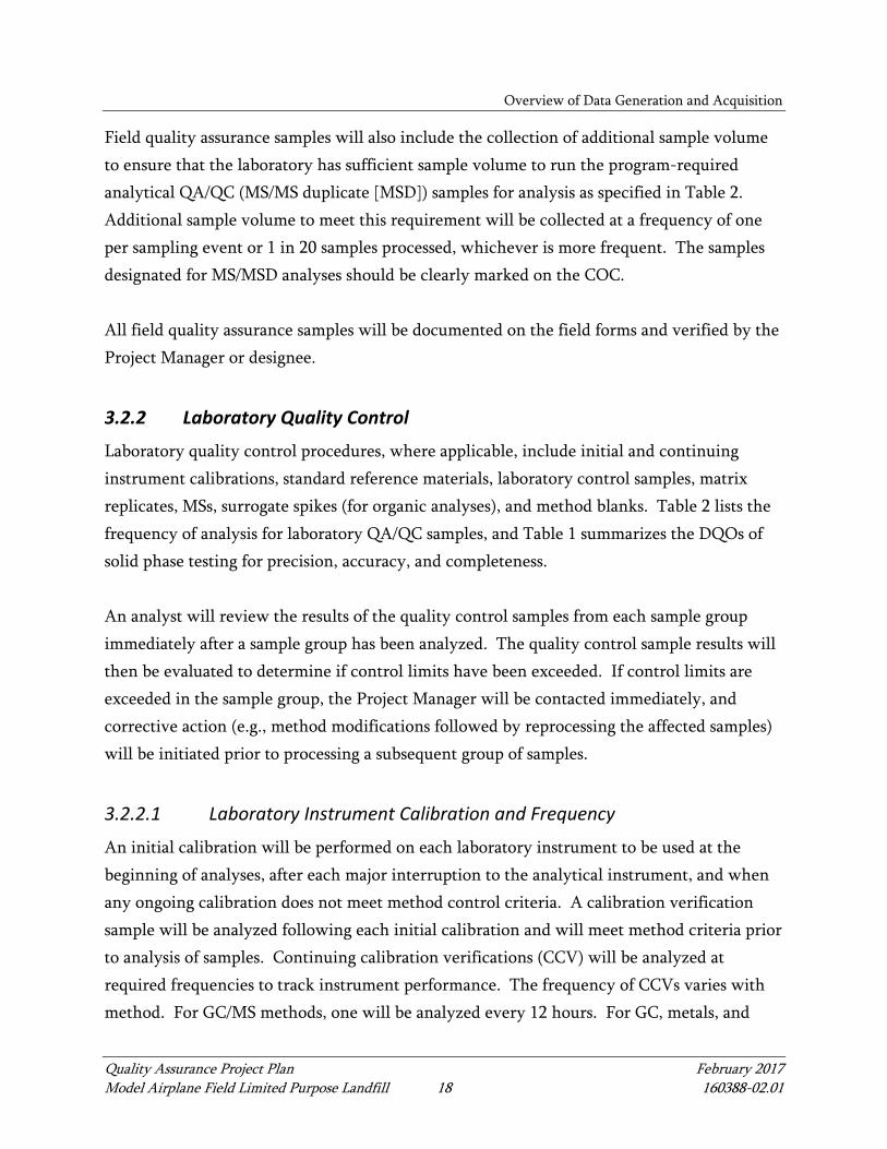
Overview of Data Generation and Acquisition
Quality Assurance Project Plan February 2017 Model Airplane Field Limited Purpose Landfill 18 160388-02.01
Field quality assurance samples will also include the collection of additional sample volume
to ensure that the laboratory has sufficient sample volume to run the program-required
analytical QA/QC (MS/MS duplicate [MSD]) samples for analysis as specified in Table 2.
Additional sample volume to meet this requirement will be collected at a frequency of one
per sampling event or 1 in 20 samples processed, whichever is more frequent. The samples
designated for MS/MSD analyses should be clearly marked on the COC.
All field quality assurance samples will be documented on the field forms and verified by the
Project Manager or designee.
3.2.2 Laboratory Quality Control
Laboratory quality control procedures, where applicable, include initial and continuing
instrument calibrations, standard reference materials, laboratory control samples, matrix
replicates, MSs, surrogate spikes (for organic analyses), and method blanks. Table 2 lists the
frequency of analysis for laboratory QA/QC samples, and Table 1 summarizes the DQOs of
solid phase testing for precision, accuracy, and completeness.
An analyst will review the results of the quality control samples from each sample group
immediately after a sample group has been analyzed. The quality control sample results will
then be evaluated to determine if control limits have been exceeded. If control limits are
exceeded in the sample group, the Project Manager will be contacted immediately, and
corrective action (e.g., method modifications followed by reprocessing the affected samples)
will be initiated prior to processing a subsequent group of samples.
3.2.2.1 Laboratory Instrument Calibration and Frequency
An initial calibration will be performed on each laboratory instrument to be used at the
beginning of analyses, after each major interruption to the analytical instrument, and when
any ongoing calibration does not meet method control criteria. A calibration verification
sample will be analyzed following each initial calibration and will meet method criteria prior
to analysis of samples. Continuing calibration verifications (CCV) will be analyzed at
required frequencies to track instrument performance. The frequency of CCVs varies with
method. For GC/MS methods, one will be analyzed every 12 hours. For GC, metals, and
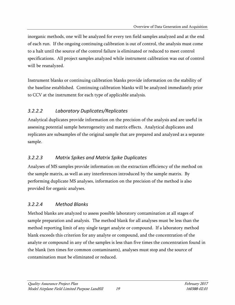
Overview of Data Generation and Acquisition
Quality Assurance Project Plan February 2017 Model Airplane Field Limited Purpose Landfill 19 160388-02.01
inorganic methods, one will be analyzed for every ten field samples analyzed and at the end
of each run. If the ongoing continuing calibration is out of control, the analysis must come
to a halt until the source of the control failure is eliminated or reduced to meet control
specifications. All project samples analyzed while instrument calibration was out of control
will be reanalyzed.
Instrument blanks or continuing calibration blanks provide information on the stability of
the baseline established. Continuing calibration blanks will be analyzed immediately prior
to CCV at the instrument for each type of applicable analysis.
3.2.2.2 Laboratory Duplicates/Replicates
Analytical duplicates provide information on the precision of the analysis and are useful in
assessing potential sample heterogeneity and matrix effects. Analytical duplicates and
replicates are subsamples of the original sample that are prepared and analyzed as a separate
sample.
3.2.2.3 Matrix Spikes and Matrix Spike Duplicates
Analyses of MS samples provide information on the extraction efficiency of the method on
the sample matrix, as well as any interferences introduced by the sample matrix. By
performing duplicate MS analyses, information on the precision of the method is also
provided for organic analyses.
3.2.2.4 Method Blanks
Method blanks are analyzed to assess possible laboratory contamination at all stages of
sample preparation and analysis. The method blank for all analyses must be less than the
method reporting limit of any single target analyte or compound. If a laboratory method
blank exceeds this criterion for any analyte or compound, and the concentration of the
analyte or compound in any of the samples is less than five times the concentration found in
the blank (ten times for common contaminants), analyses must stop and the source of
contamination must be eliminated or reduced.

Overview of Data Generation and Acquisition
Quality Assurance Project Plan February 2017 Model Airplane Field Limited Purpose Landfill 20 160388-02.01
3.2.2.5 Laboratory Control Samples
Laboratory control samples are analyzed to assess possible laboratory bias at all stages of
sample preparation and analysis. The laboratory control sample is a matrix-dependent spiked
sample prepared at the time of sample extraction along with the preparation of the sample
and MS. The laboratory control sample will provide information on the accuracy of the
analytical process and, when analyzed in duplicate, will provide precision information as
well.
3.2.2.6 Laboratory Deliverables
Data packages will be checked for completeness immediately upon receipt from the
laboratory to ensure that data and QA/QC information requested in Section 2.4.2 are present.
3.3 Instrument/Equipment Testing, Inspection, and Maintenance
Requirements
This section describes procedures for testing, inspection, and maintenance of field and
laboratory equipment.
3.3.1 Field Instruments/Equipment
In accordance with the quality assurance program, Anchor QEA shall maintain an inventory
of field instruments and equipment. The frequency and types of maintenance will be based
on the manufacturer’s recommendations and/or previous experience with the equipment.
The Anchor QEA FC will be responsible for the preparation, documentation, and
implementation of the preventative maintenance program. The equipment maintenance
information will be documented in the instrument’s calibration log. The frequency of
maintenance is dependent on the type and stability of the equipment, the methods used, the
intended use of the equipment, and the recommendations of the manufacturer. Detailed
information regarding the calibration and frequency of equipment calibration is provided in
specific manufacturer’s instruction manuals.
Overview of Data Generation and Acquisition
Quality Assurance Project Plan February 2017 Model Airplane Field Limited Purpose Landfill 21 160388-02.01
All maintenance records will be verified prior to each sampling event. The FC will be
responsible for verifying that required maintenance has been performed prior to using the
equipment in the field.
3.3.2 Laboratory Instruments/Equipment
In accordance with the Quality Assurance Program, the laboratory shall maintain an
inventory of instruments and equipment and the frequency of maintenance will be based on
the manufacturer’s recommendations and previous experience with the equipment.
The laboratory preventative maintenance program, as detailed in the laboratory Quality
Assurance Plan, is organized to maintain proper instrument and equipment performance,
and to prevent instrument and equipment failure during use. The program considers
instrumentation, equipment, and parts that are subject to wear, deterioration, or other
changes in operational characteristics; the availability of spare parts; and the frequency at
which maintenance is required. Any equipment that has been overloaded, mishandled, gives
suspect results, or has been determined to be defective will be taken out of service, tagged
with the discrepancy noted, and stored in a designated area until the equipment has been
repaired. After repair, the equipment will be tested to ensure that it is in proper operational
condition. The client will be promptly notified in writing if defective equipment casts doubt
on the validity of analytical data. The client will also be notified immediately regarding any
delays due to instrument malfunctions that could impact holding times.
Laboratories will be responsible for the preparation, documentation, and implementation of
the preventative maintenance program. All maintenance records will be checked according
to the schedule on an annual basis and recorded by the responsible individual. The
Laboratory Manager, or designee, shall be responsible for verifying compliance.
3.4 Instrument Calibration
Proper calibration of equipment and instrumentation is an integral part of the process that
provides quality data. Instrumentation and equipment used to generate data must be
calibrated at a frequency that ensures sufficient and consistent accuracy and reproducibility.

Overview of Data Generation and Acquisition
Quality Assurance Project Plan February 2017 Model Airplane Field Limited Purpose Landfill 22 160388-02.01
3.4.1 Field Instrument/Equipment Calibration
Field equipment will be calibrated prior to each sampling event according to manufacturer’s
recommendations using manufacturer’s standards. A calibration check will be performed at
the end of the day. The equipment, calibration, and maintenance information will be
documented in the instrument calibration log. The frequency of calibration is dependent on
the type and stability of the equipment, the methods used, the intended use of the
equipment, and the recommendations of the manufacturer. Detailed information regarding
the calibration and frequency of equipment calibration is provided in specific manufacturer’s
instruction manuals.
Equipment that fails calibration or becomes inoperable during use will be removed from
service and tagged (time and date of action) to prevent inadvertent use. Such equipment will
be satisfactorily recalibrated or repaired and tagged (date and time of return to service) prior
to use.
3.4.2 Laboratory Instrument/Equipment Calibration
As part of their quality control program, laboratories perform two types of calibrations. A
periodic calibration is performed at prescribed intervals (i.e., balances, drying ovens,
refrigerators, and thermometers), and operational calibrations are performed daily, at a
specified frequency, or prior to analysis (i.e., initial calibrations) according to method
requirements. Calibration procedures and frequency are discussed in the laboratory Quality
Assurance Plan. Calibrations are discussed in the laboratory standard operating procedures
(SOPs) for analyses.
The Laboratory Manager will be responsible for ensuring that the laboratory instrumentation
is calibrated in accordance with specifications. Implementation of the calibration program
shall be the responsibility of the respective laboratory Group Supervisors. Recognized
procedures (EPA, ASTM, or manufacturer’s instructions) shall be used when available.
Physical standards (i.e., weights or certified thermometers) shall be traceable to nationally
recognized standards such as the National Institute of Standards and Technology (NIST).

Overview of Data Generation and Acquisition
Quality Assurance Project Plan February 2017 Model Airplane Field Limited Purpose Landfill 23 160388-02.01
Chemical reference standards shall be NIST standard reference materials or vendor-certified
materials traceable to these standards.
The calibration requirements for each method and respective corrective actions shall be
accessible, either in the laboratory SOPs or the laboratory’s Quality Assurance Plan for each
instrument or analytical method in use. All calibrations shall be preserved on electronic
media.
3.5 Inspection/Acceptance Requirements for Supplies and Consumables
Inspection and acceptance of field supplies, including laboratory-prepared sampling bottles,
will be performed by the FC. All primary chemical standards and standard solutions used in
this project, either in the field or laboratory, will be traceable to documented, reliable,
commercial sources. Standards will be validated to determine their accuracy by comparison
with an independent standard. Any impurities found in the standard will be documented.
3.6 Data Management
Field data sheets will be checked for completeness and accuracy by the FC prior to delivery
to the Data Manager. All data generated in the field will be documented on hard copy and
provided to the Data Manager, who is responsible for the data’s entry into the database. All
manually entered data will be checked by a second party. Field documentation will be filed
in the main project file after data entry and checking are complete.
Laboratory data will be provided to the Data Manager in the EQuIS electronic format.
Laboratory data that is electronically provided and loaded into the database will undergo a
10% check against the laboratory hard-copy data. Data will be reviewed manually, and
qualifiers, if assigned, will be entered manually. The accuracy of all manually entered data
will be verified by a second party. Data tables and reports will be exported from EQuIS to
MS Excel tables.

Quality Assurance Project Plan February 2017 Model Airplane Field Limited Purpose Landfill 24 160388-02.01
4 ASSESSMENTS AND RESPONSE ACTIONS
Once data are received from the laboratory, a number of quality control procedures will be
followed to provide an accurate evaluation of the data quality. Specific procedures will be
followed to assess data precision, accuracy, and completeness.
4.1 Compliance Assessments
Laboratory and field performance audits consist of on-site reviews of quality assurance
systems and equipment for sampling, calibration, and measurement. Laboratory audits will
not be conducted as part of this study. However, all laboratory audit reports will be made
available to the project Project Manager upon request. The laboratory is required to have
written procedures addressing internal QA/QC. These procedures have been submitted and
the project Project Manager will review them to ensure compliance with the QAPP. The
laboratory must ensure that personnel engaged in sampling and analysis tasks have
appropriate training. The laboratory will, as part of the audit process, provide for
consultant’s review of written details of any and all method modifications planned.
4.2 Response and Corrective Actions
The following sections identify the responsibilities of key project team members and actions
to be taken in the event of an error, problem, or non-conformance to protocols identified in
this document.
4.2.1 Field Activities
The FC will be responsible for correcting equipment malfunctions during the field sampling
effort. The Project Manager will be responsible for resolving situations identified by the FC
that may result in non-compliance with this QAPP. All corrective measures will be
immediately documented in the field logbook.
4.2.2 Laboratory
The laboratory is required to comply with its SOPs. The Laboratory Manager will be
responsible for ensuring that appropriate corrective actions are initiated as required for

Assessments and Response Actions
Quality Assurance Project Plan February 2017 Model Airplane Field Limited Purpose Landfill 25 160388-02.01
conformance with this QAPP. All laboratory personnel will be responsible for reporting
problems that may compromise the quality of the data.
The Laboratory Manager will be notified if any quality control sample grossly exceeds the
project-specified control limits. The analyst will identify and correct the anomaly before
continuing with the sample analysis. If the anomaly cannot be corrected, the Laboratory
Manager will document the corrective action taken in a memorandum submitted to the
Project Manager within 5 days of the initial notification. A narrative describing the
anomaly, the steps taken to identify and correct the anomaly, and the treatment of the
relevant sample batch (i.e., recalculation, reanalysis, and re-extraction) will be submitted
with the data package in the case narrative.
4.3 Reports to Management
Quality assurance reports to management include verbal status reports, written reports on
field sampling activities and laboratory processes, data review reports, and final project
reports. These reports shall be the responsibility of the Project Manager.
The FC will prepare progress reports following each sampling event. The Project Manager
also will prepare progress reports after the sampling is completed and samples have been
submitted for analysis, when information is received from the laboratory, and when analysis
is complete. The status of the samples and analysis will be indicated with emphasis on any
deviations from the QAPP. A data report will be written after reviewed data are available
for each sampling event.

Quality Assurance Project Plan February 2017 Model Airplane Field Limited Purpose Landfill 26 160388-02.01
5 DATA REVIEW AND USABILITY
This section describes the processes that will be used to review project data quality.
5.1 Data Review and Verification
During the data review process, analytical data will be evaluated for method and laboratory
quality control compliance, and their validity and applicability for program purposes will be
determined. Based on the findings of the data review process, data qualifiers may be
assigned. The reviewed project data, including qualifiers, will be entered into the project
database, thus enabling this information to be retained or retrieved, as needed.
5.2 Data Review Methods
Data review includes signed entries by the field and laboratory technicians on field data
sheets and laboratory datasheets, respectively; review for completeness and accuracy by the
FC and Laboratory Manager; review by the Data Manager for outliers and omissions; and the
use of quality control criteria to accept or reject specific data. All data will be entered into
the EQuIS database and a raw data file printed. A second data manager or designee will
perform a 10% verification of the database raw data file. One hundred percent of manually
entered qualifiers will be verified. Any errors found will be corrected on the raw data
printout sheet. After the raw data are checked, the top sheet will be marked with the date
the checking is completed and the initials of the person doing the checking. Any errors in
the raw data file will be corrected and the database established.
All laboratory data will be reviewed to determine whether all DQOs have been met, and that
appropriate corrective actions have been taken, when necessary. The Project Manager or
designee will be responsible for the final review of all data generated from analyses of
samples.
The first level of review will take place in the laboratory as the data are generated. The
laboratory department manager or designee will be responsible for ensuring that the data
generated meet minimum QA/QC requirements and that the instruments were operating
under acceptable conditions during generation of data. DQOs will also be assessed at this

Data Review and Usability
Quality Assurance Project Plan February 2017 Model Airplane Field Limited Purpose Landfill 27 160388-02.01
point by comparing the results of quality control measurements with pre-established criteria
as a measure of data acceptability.
The results of the data quality review, including text assigning qualifiers in accordance with
the EPA National Functional Guidelines (EPA 1999, 2004) and a tabular summary of
qualifiers, will be generated by the Data Manager and submitted to the Project Manager for
final review and confirmation of the data.
5.3 Reconciliation with User Requirements
The Project Manager will review data after each survey to determine if DQOs have been
met. If data do not meet the project’s specifications, the Project Manager will review the
errors and determine if the problem is due to calibration/maintenance, sampling techniques,
or other factors and will suggest corrective action. It is expected that the problem would be
able to be corrected by retraining, revision of techniques, or replacement of supplies or
equipment; if not, the DQOs will be reviewed for feasibility. If specific DQOs are not
achievable, the Project Manager will recommend appropriate modifications. Any revisions
will require approval by Ecology.

Quality Assurance Project Plan February 2017 Model Airplane Field Limited Purpose Landfill 28 160388-02.01
6 REFERENCES
ASTM (American Society for Testing and Materials), 2002. Standard Practices for Use of the
Term Precision and Bias in ASTM Test Methods. ASTM 177-90a. ASTM
International.
Ecology, 2008. Sediment Sampling and Analysis Plan Appendix. Ecology Publication No.
03-09-043. Sediment Source Control Standards User Manual, Washington State
Department of Ecology Sediment Management Unit. Revised February 2008.
EPA (U.S. Environmental Protection Agency), 1986. Test Methods for the Evaluation of
Solid Waste: Physical/Chemical Methods, 3rd Edition. EPA SW-846, 1986.
EPA, 1999. USEPA Contract Laboratory Program National Functional Guidelines for
Organic Data Review. EPA540/R-99/008, October 1999.
EPA, 2004. USEPA Contract Laboratory Program National Functional Guidelines for
Inorganic Data Review. EPA540-R-04-004, October 2004.
EPA, 2005. National Functional Guidelines for Chlorinated Dibenzo-p-Dioxins (CDDs) and
Chlorinated Dibenzofurans (CDFs) Data Review. OSWER 9240.1-51, EPA-540-R-05-
001. September 2005.
Lombard, S.M., and C.J. Kirchmer, 2004. Guidelines for Preparing Quality Assurance Project
Plans for Environmental Studies. Washington State Department of Ecology
Environmental Assessment Program. July 2004. Publication Number 04-03-030.

TABLES
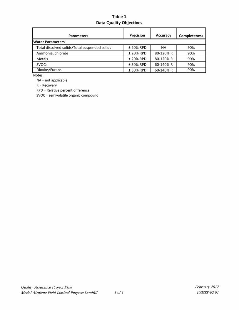
Table 1Data Quality Objectives
Quality Assurance Project PlanModel Airplane Field Limited Purpose Landfill 1 of 1
February 2017 160388-02.01
Precision Accuracy Completeness
± 20% RPD NA 90%± 20% RPD 80-120% R 90%± 20% RPD 80-120% R 90%± 30% RPD 60-140% R 90%± 30% RPD 60-140% R 90%
Notes:NA = not applicableR = RecoveryRPD = Relative percent differenceSVOC = semivolatile organic compound
Parameters
Dioxins/Furans
Ammonia, chlorideMetalsSVOCs
Water ParametersTotal dissolved solids/Total suspended solids

Table 2
Laboratory and Field Quality Assurance/Quality Control Sample and Analysis Summary
Field Duplicates Temperature Blank Initial Calibrationa
Ongoing
Calibration Replicates
Matrix
Spikes
LCS Blank
Spike
Matrix Spike
Duplicates
Method
Blanks
Surrogate
Spikes
1 per event or 1 per 20 samples
1 per cooler Each batch b NA1 per 20 samples
NA NA NA NA NA
1 per event or 1 per 20 samples
1 per cooler Daily or each batch1 per 10 samples
1 per 20 samples
1 per 20 samples
1 per 20 samples
NA1 per 20 samples
NA
1 per event or 1 per 20 samples
1 per cooler Daily1 per 10 samples
1 per 20 samples
1 per 20 samples
1 per 20 samples
NA1 per 20 samples
NA
1 per event or 1 per 20 samples
1 per cooler As needed c Every 12 hours NA Nad1 per 20 samples Nad
1 per 20 samples
Every sample
1 per event or 1 per 20 samples
1 per cooler As needed c Every 12 hours NA1 per 20 samples
1 per 20 samples
1 per 20 samples
1 per 20 samples
Every sample
Notes: a = Initial calibration verification and calibration blank must be analyzed at the beginning of each batch.b = Calibration and certification of drying ovens and weighing scales are conducted bi‐annually.c = Initial calibrations are considered valid until the ongoing continuing calibration no longer meets method specifications. At that point, a new initial calibration is performed.d = Isotope dilution required per method.EPH = extractable petroleum hydrocarbonsLCS = laboratory control sampleNA = not applicablePCB = polychlorinated biphenylSVOC = semivolatile organic compoundTPH = total petroleum hydrocarbonsVOC = volatile organic compoundVPH = volatile petroleum hydrocarbons
SVOCs
Metals (Total)
Field Quality Assurance Samples Laboratory Quality Control Elements
Analysis Type
Total dissolved solids/Total suspended solids
Ammonia, chloride
Dioxin/Furans
Quality Assurance Project Plan
Model Airplane Field Limited Purpose Landfill 1 of 1February 2017 160388-02.01

Table 3
Groundwater Analytes, Analytical Methods, and Laboratory Reporting Limits
Analytical Method Method Detection Limit Limit of Detection Limit of Quantitation
Conventional and Physical Parameters (mg/L)
Total dissolved solids SM2540C ‐‐ ‐‐ 5.0Total Suspended Solids SM 2450D ‐‐ ‐‐ 1.0Total sulfides USEPA 376.2 ‐‐ ‐‐ 0.05Chloride USEPA 300.0 ‐‐ ‐‐ 0.1Ammonia USEPA 350.1 ‐‐ ‐‐ 0.1
Metals, Total (µg/L)
Antimony USEPA 6020A 0.01 0.1 0.2Arsenic USEPA 6020A 0.048 0.1 0.2/0.5Beryllium USEPA 6020A 0.021 0.1 0.2Barium USEPA 6020A 0.02 0.25 0.5Cadmium USEPA 6020A 0.01 0.05 0.1Chromium USEPA 6020A 0.045 0.25 0.5Chromium, hexavalent USEPA 3060A/7196A ‐‐ ‐‐ 0.04Copper USEPA 6020A 0.158 0.25 0.5Lead USEPA 6020A 0.046 0.05 0.1Mercury USEPA 7471A 0.0069 0.05 0.1Nickel USEPA 6020A 0.079 0.25 0.5Selenium USEPA 6020A 0.127 0.25 0.5Silver USEPA 6020A 0.008 0.1 0.2Thallium USEPA 6020A 0.004 0.1 0.2Zinc USEPA 6020A 0.497 2 4
Semivolatile Organic Compounds: Low Level PAH (µg/L)
1‐Methylnaphthalene USEPA 8270D/SIM 0.00088 0.005 0.012‐Methylnaphthalene USEPA 8270D/SIM 0.00072 0.005 0.01Acenaphthene USEPA 8270D/SIM 0.00083 0.005 0.01Acenaphthylene USEPA 8270D/SIM 0.00081 0.005 0.01Anthracene USEPA 8270D/SIM 0.00058 0.005 0.01Benzo(a)anthracene USEPA 8270D/SIM 0.00127 0.005 0.01Benzo(a)Pyrene USEPA 8270D/SIM 0.00114 0.005 0.01Benzo(g,h,i)Perylene USEPA 8270D/SIM 0.00187 0.005 0.01Benzo(b)fluoranthene USEPA 8270D/SIM 0.00254 0.005 0.01Benzo(k)fluoranthene USEPA 8270D/SIM 0.00085 0.005 0.01Benzofluoranthene(s) (total) USEPA 8270D/SIM 0.00339 0.005 0.01Chrysene USEPA 8270D/SIM 0.00157 0.005 0.01Dibenz(a,h)Anthracene USEPA 8270D/SIM 0.00097 0.005 0.01Dibenzofuran USEPA 8270D/SIM 0.00094 0.005 0.01Fluoranthene USEPA 8270D/SIM 0.00092 0.005 0.01Fluorene USEPA 8270D/SIM 0.00141 0.005 0.01Indeno(1,2,3‐cd)Pyrene USEPA 8270D/SIM 0.00182 0.005 0.01Naphthalene USEPA 8270D/SIM 0.00085 0.005 0.01Phenanthrene USEPA 8270D/SIM 0.00101 0.005 0.01Pyrene USEPA 8270D/SIM 0.0007 0.005 0.01
Dioxins/Furans (µg/L)
2,3,7,8‐TCDF USEPA 1613B 0.00000203 0.000005 0.000012,3,7,8‐TCDD USEPA 1613B 0.00000282 0.000005 0.000011,2,3,7,8‐PeCDF USEPA 1613B 0.00000608 0.000025 0.000052,3,4,7,8‐PeCDF USEPA 1613B 0.00000769 0.000025 0.000051,2,3,7,8‐PeCDD USEPA 1613B 0.00000734 0.000025 0.000051,2,3,4,7,8‐HxCDF USEPA 1613B 0.00000727 0.000025 0.000051,2,3,6,7,8‐HxCDF USEPA 1613B 0.00000976 0.000025 0.000052,3,4,6,7,8‐HxCDF USEPA 1613B 0.00000514 0.000025 0.000051,2,3,7,8,9‐HxCDF USEPA 1613B 0.0000036 0.000025 0.000051,2,3,4,7,8‐HxCDD USEPA 1613B 0.00000338 0.000025 0.000051,2,3,6,7,8‐HxCDD USEPA 1613B 0.00000522 0.000025 0.000051,2,3,7,8,9‐HxCDD USEPA 1613B 0.0000045 0.000025 0.000051,2,3,4,6,7,8‐HpCDF USEPA 1613B 0.00001028 0.000025 0.000051,2,3,4,7,8,9‐HpCDF USEPA 1613B 0.00000849 0.000025 0.000051,2,3,4,6,7,8‐HpCDD USEPA 1613B 0.0000073 0.000025 0.00005OCDF USEPA 1613B 0.0000162 0.00005 0.0001OCDD USEPA 1613B 0.0000383 0.00005 0.0001
Notes:Method Detection Limits (MDL) are determined by 40 CFR Part 136 and included for informational purposes.
With the exception of metals, all detected concentrations between the LOD and LOQ will be reported as estimated. Non‐detected concentrations will be reported at the LOQ.
Parameter
Limit of Detection (LOD) and Limit of Quantitation (LOQ) values are updated quarterly and are subject to change slightly as new detection and quantitation studies are completed.
Final MDL, LOD and LOQ values may differ slightly based on sample dry weight correction, adjustment for sample size and sample dilution due to matrix interference, or non‐target analytes.
Quality Assurance Project Plan
Model Airplane Field Limited Purpose Landfill 1 of 1February 2017 160388-02.01

• WA!HIMGTDI STAii Solid Waste Permit Application Permit Number
(For offlclal use only) D ! p AR T w r I I Dr
ECOLOGY Chapter 173-350 WAC and Chapter 173-351 WAC
PART I. Applicant Information Application Date County where facility is located
09/03/2015 Kitsao Name of Applicant (see WAC 17:J.350.715(3) or WAC 173-351-730(7) Applicant is: for appropriate evidence of authority):
Jon Rose lr2ll Facility owner
D Facility operator Company Name, Government Entity, etc.: D Other(specify) Pope Resources, LP/OPG Properties LLC
Applicant's Position in Company or Government Entity:
Vice President - Real Estate
Applicant Mailing Address: Applicant phone:
360.394.0519
Street: Fax:
19950 7th Avenue NE, Suite 200 e-mail address:
City:
Poulsbo [email protected] State: Zip:
Washington 98370
PART II. Solid Waste Activity/Facility Type Identify all solid waste handling activities/facilities that are included in this permit application.
!You must comolete the annlicable PART II forms below for each activitv/facilitv tvne with this annlication.l
D Municipal Solid Waste Landfill Unit per chapter 173-351 WAC D Surface impoundment per WAC 173-350-330
D Composting per WAC 173-350-220 D Tank per WAC 173-350-330
D Land application per WAC 173-350-230 D Waste tire storage per WAC 173-350-350
D Energy recovery and incineration per WAC 173-350-240 D Moderate risk waste per WAC 173-350-360
Intermediate solid waste handling per WAC 173-350-310 lr2l] Limited purpose landfill per WAC 173-350-400
D Material recovery facility D Inert waste landfill per WAC 173-350-410
D Transfer station D Other per WAC 173-350-490 (specify)
D Bailing and compaction site
Oorop Box
D Decant Facility
Oother
D Piles used for storage or treatment per WAC 173-350-320
D Municipal Solid Waste Landfill Unit
Attach the following as required under WAC 173-351-730 I Location of Documents
Engineering plans, reports and specifications per WAC 173-351-730(5)(a) I
Ecology is an Equal Opportunity Employer. ECY 040-152 (1/03)
Page I

Demonstrations that the facility meets the location standards of WAC 173-351-130 and 173-351-140
Hydrogeologic report and water quality monitoring plan, and demonstrations, prepared in accordance with WAC 173-351-400
A plan of operations, and demonstrations, meeting the requirements of WAC 173-351-200, 173-351-210 and 173-351-220
An engineering report comprehensively describing the existing site conditions and an analysis of the facility, including closure, post-closure criteria and any necessary demonstrations per WAC 173-351-730(5)(b)
An engineering report containing a description of the existing site conditions and an analysis of the proposed facility per WAC 173-351-730(5)(c)
A construction quality assurance and quality control plan per WAC 173-351-730(6)
Closure and post-closure plans per WAC 173-351-500
Documentation per WAC 173-351-730(1)((b)(viii) for managing leachate
For small landfills, demonstration of WAC 173-351-010(2)(c) NAO
Demonstration of how the facility conforms with the approved local comprehensive solid waste manaQement plan
Additional information required by the jurisdictional health department
ID Composting Facilities
Attach the following as required under WAC 173-350-220(8): Location of Documents
Engineering reports/plans and specifications that address the design standards of WAC 173-350-220(3)
A plan of operation meeting the requirements of WAC 173-350-220(4)
A closure plan meeting the requirements of WAC 173-350-220(6)
Additional information required by the jurisdictional health department
ID Land Application
Attach the following as required under WAC 173-350-230(8): Location of Documents
Contact information as required under WAC 173-350-230(8)(a)(i)
Statement of intended use as required under WAC 173-350-230(8)(a)(ii)
Analysis of each waste stream as required under WAC 173-350-230(8)(a)(iii)
A comprehensive site characterization as required under WAC 173-350-230(8)(a)(iv)
A plan of operation meeting the requirements of WAC 173-350-230(4)
Additional information required by the jurisdictional health department
ID Energy Recovery and Incineration Facilities
Attach the following as required under WAC 173-350-240(9): Location of Documents
Engineering reports/plans and specifications that address the design of storage and handling facilities on-site for incoming waste as well as fly ash, bottom ash and any other waste produced by air or water pollution controls
Ecology is an Equal Opportunity Employer. ECY 040-152 ( 1/03)
Page2

Engineering reports/plans and specifications that address the design of the incinerator or thermal treater, including charging or feeding systems, combustion air systems, ash handling systems, and air pollution and water pollution control systems. Include design of instrumentation and monitoring systems.
A plan of operation meeting the requirements of WAC 173-350-240(4)
A closure plan meeting the requirements of WAC 173-350-240(6)
Additional information required by the jurisdictional health department
D Intermediate Solid Waste Handling Facilities (Material Recovery Facilities, Transfer Stations, Baling and Compaction Sites, Decant Facilities)
Attach the following as required under WAC 173-350-310(9): Location of Documents
Engineering reports/plans and specifications that address the design standards of WAC 173-350-310(4)(a)
A plan of operation meeting the requirements of WAC 173-350-310(5)(e)
A closure plan meeting the requirements of WAC 173-350-310(7)
Additional information required by the jurisdictional health department
D Intermediate Solid Waste Handling Facilities (Drop Boxes)
Attach the following as required under WAC 173-350-310(9): Location of Documents
Engineering reports/plans and specifications that address the design standards of WAC 173-350-310(4)(b)
A plan of operation meeting the requirements of WAC 173-350-310(5)(e)
A closure plan meeting the requirements of WAC 173-350-310(7)
Additional information required by the jurisdictional health department
D Piles for Treatment and Storage
Attach the following as required under WAC 173-350-320(8): Location of Documents
The design of fire control features
Engineering reports/plans and specifications that address the design standards of WAC 173-350-320(3)
A plan of operation meeting the requirements of WAC 173-350-320(4)
A closure plan meeting the requirements of WAC 173-350-320(6)
Additional information required by the jurisdictional health department
Ecology is an Equal Opportunity Employer. ECY 040-152 ( 1/03)
Page 3
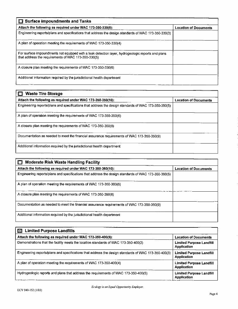
ID Surface Impoundments and Tanks
Attach the following as required under WAC 173-350-330(8): Location of Documents
Engineering reports/plans and specifications that address the design standards of WAC 173-350-330(3)
A plan of operation meeting the requirements of WAC 173-350-330(4)
For surface impoundments not equipped with a leak detection layer, hydrogeologic reports and plans that address the requirements of WAC 173-350-330(5)
A closure plan meeting the requirements of WAC 173-350-330(6)
Additional information required by the jurisdictional health department
ID Waste Tire Storage
Attach the following as required under WAC 173-350-350(10): Location of Documents
Engineering reports/plans and specifications that address the design standards of WAC 173-350-350(5)
A plan of operation meeting the requirements of WAC 173-350-350(6)
A closure plan meeting the requirements of WAC 173-350-350(8)
Documentation as needed to meet the financial assurance requirements of WAC 173-350-350(9)
Additional information required by the jurisdictional health department
ID Moderate Risk Waste Handling Facility
Attach the following as required under WAC 173-350-360(10): Location of Documents
Engineering reports/plans and specifications that address the design standards of WAC 173-350-360(5)
A plan of operation meeting the requirements of WAC 173-350-360(6)
A closure plan meeting the requirements of WAC 173-350-360(8)
Documentation as needed to meet the financial assurance requirements of WAC 173-350-360(9)
Additional information required by the jurisdictional health department
11811 Limited Purpose Landfills
Attach the following as required under WAC 173-350-400(9): Location of Documents
Demonstrations that the facility meets the location standards of WAC 173-350-400(2) Limited Purpose Landfill Application
Engineering reports/plans and specifications that address the design standards of WAC 173-350-400(3) Limited Purpose Landfill Application
A plan of operation meeting the requirements of WAC 173-350-400(4) Limited Purpose Landfill Application
Hydrogeologic reports and plans that address the requirements of WAC 173-350-400(5) Limited Purpose Landfill Application
Ecology is an Equal OpporlUnfty Employer. ECY 040-152 (1/03)
Page4

A closure plan meeting the requirements of WAC 173-350-400(6) Limited Purpose Landfill Application
A post-closure plan meeting the requirements of WAC 173-350-400(7) Limited Purpose Landfill Application
Documentation as needed to meet the financial assurance requirements of WAC 173-350-400(8) Limited Purpose Landfill Application
Additional information required by the jurisdictional health department Limited Purpose Landfill Application
D Inert Waste Landfill
Attach the following as required under WAC 173-350-410(8): Location of Documents
Engineering reports/plans and specifications that address the design standards of WAC 173-350-410(3)
A plan of operation meeting the requirements of WAC 173-350-410(4)
Additional information required by the jurisdictional health department
PART Ill. Facility Information
Name of Facility
Model Airnlane Field Facility Address: Facility Mailing Address (if different)
Street: Street:
Site is located west of State Route 19950 7th Avenue NE, Suite 200 (SR) 104 in Port Gamble at City: approximately 47°50'52"N and
Poulsbo 122°35' 14"
City: Port Gamble State: Washington Zip: 98370
State: WA Zip: 98364 Property Tax Account Number(s) Facility Site Zoning
Parcel identification/account Rural wooded numbers:
072702-1-018-2004 072702-1-015-2007 072702-1-016-2006 072702-1-017-2005
D For a facility/activity to be permitted under chapter 173-350 WAC, attach a facility/vicinity map per WAC 173-350-715 (d)
Reau ired ar Existina Permits at the Facilitv Site
Type of permit /check box) Need to Existing Permit Obtain
Regulating Authority Permit# Expiration Date
D Solid waste permit
Ecology is an Equal Opportunity Employer. ECY 040-152 (t/03)
Pages
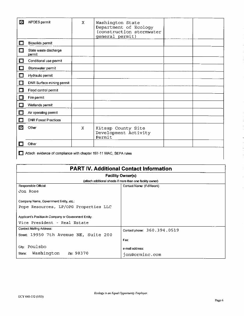
IT81I NPDES permit X Washington State Department of Ecology (construction stormwater qeneral permit)
ID Biosolids permit
ID State waste discharge permit
ID Conditional use permit
ID Stonmwater perm it
ID Hydraulic permit
ID DNR Surface mining permit
ID Flood control permit
ID Fire permit
ID Wetlands permit
ID Air operating perm it
ID DNR Forest Practices
IT81I Other X Kitsap County Site Development Activity Permit
ID Other
ID Attach evidence of compliance with chapter 197-11 WAC, SEPA rules
PART IV. Additional Contact Information Facility Owner(s)
(attach additional sheets if more than one facility owner) Responsible Official: Contact Name: (if different)
Jon Rose
Company Name, Government Entity, etc.:
Pope Resources, LP/OPG Properties LLC
Applicant's Position in Company or Government Entity:
Vice President - Real Estate Contact Mailing Address:
Contact phone: 360.394.0519 Street 19950 7th Avenue NE, Suite 200
Fax:
City: Poulsbo e-mail address:
State: Washington Zip: 983 70 [email protected]
Ecology is an Equal Opportunity Employer. ECY 040-152 (1/03)
Page6

Facility Operator(s) Same as Facility Owner(s) [2'JI YES
(attach additional sheets if more than one facility operator)
Responsible Official: Contact Name: (if different)
Company Name, Government Entity, etc.:
Applicant's Position in Company or Government Entity:
Contact Mailing Address: Contact phone:
Street:
Fax:
City: e-mail address:
State: Zip:
Property Owner(s)· Same as Facility Ow ner(s) [2'JI YES
(attach additional sheets if more than one property owner)
Property Owners Name(s): Contact Name:(if different)
Mailing Address: Phone:
Street:
City: Fax:
State: Zip: e-mail address:
PARTV. Signature and Verification of Applicant (Refer to WAC 173-350. 715(3) or WAC 173-351-730(7) for appropriate evidence of authority)
I certify under penalty of law that I have personally examined and am familiar with the information submitted in this application and all attachments and that, based on my inquiry of those individuals immediately responsible for obtaining the information, I believe that the information is true accurate and complete. I am aware that there are significant penalties for submitting false information, including the possibility of fine and imprisonment.
Jon Rose /\ Vi ce Presiden t - Real Estate I (Applicant's Sii il atL
tV (Title)
"'- /, ll · Jl, . 15 I (Applicant's ~ ig~ ~ture}' (Date)
\J PART VI. Notary Public Verification Sta te o f 'NAt..Y\ i"'1a ~ t...l County o f ~it«,A'1 J Signed or attested before me on ~'t\' J. S ff~ \\· \ t,. 1$" by S,q~ J. &re:f",fi;f..1
'§. t: -- ~~ ~~~ON~~ ./,.nA j ~~!!1 • /~( '""'ft :, "'~ ~ I i atlOTARv I ) (Signature) " 77
(sel o~ tam~ ft> ~ ~ ¥i ~ ~ ~ 0~ My appointment expires: ! ~~~~~ .. ·~§ ~ ... . _,....._··~(j~ l 'l •15 • 1..0 I
~,,':./: WAS~~# fDateJ
Ecology is an Equal Opporlunily Employer. ECY 040- 152 (1/03)
Page 7

APPENDIX G PLAN OF OPERATION MODEL AIRPLANE FIELD LIMITED PURPOSE LANDFILL APPLICATION PORT GAMBLE
Prepared for Pope Resources, LP/OPG Properties, LLC
Prepared by Anchor QEA, LLC
720 Olive Way, Suite 1900
Seattle, Washington 98101
March 2017 Revision

Appendix G: Plan of Operation March 2017 Revision Model Airplane Field Limited Purpose Landfill Application i 160388-02.01 Port Gamble
TABLE OF CONTENTS 1 INTRODUCTION ................................................................................................................. 1
2 ACCEPTABLE SOLID WASTE ............................................................................................. 2
2.1 Visual Inspection ..............................................................................................................2
2.2 Bulk Sediment Chemistry ................................................................................................3
2.3 Leachate Chemistry ..........................................................................................................3
3 SOLID WASTE HANDLING ................................................................................................ 5
3.1 Operational Procedure .....................................................................................................5
3.2 Acceptance Procedures and Procedures for Unacceptable Waste ................................6
4 INSPECTION AND MAINTENANCE OF LANDFILL STRUCTURES AND SYSTEMS ........ 7
5 SAFETY AND EMERGENCY PLANS ................................................................................... 9
5.1 Health and Safety Plan .....................................................................................................9
5.2 Emergency Response Plan .............................................................................................10
6 WEIGHT AND VOLUME FORMS ..................................................................................... 11
List of Tables Table 1 Landfill Material Acceptance Criteria
List of Figures Figure 1 Plan of Operations
List of Attachments Attachment 1 Forms

Appendix G: Plan of Operation March 2017 Revision Model Airplane Field Limited Purpose Landfill Application ii 160388-02.01 Port Gamble
LIST OF ACRONYMS AND ABBREVIATIONS BMP best management practice cPAH carcinogenic polycyclic aromatic hydrocarbon cy cubic yards HASP Health and Safety Plan kg kilogram Landfill Limited Purpose Landfill MAF Model Airplane Field Mill Site Pope & Talbot Sawmill Site Plan Plan of Operation PR/OPG Pope Resources, LP/Olympic Property Group, LLC TEQ toxicity equivalency quotient WSDOT Washington State Department of Transportation

Appendix G: Plan of Operation March 2017 Revision Model Airplane Field Limited Purpose Landfill Application 1 160388-02.01 Port Gamble
1 INTRODUCTION
The Port Gamble Bay sediment cleanup project will result in dredging and excavation of mixed sediment and wood debris (referred to as dredged material) adjacent to the former Pope & Talbot Sawmill Site (Mill Site). Some or all of these materials, along with similar Mill Site habitat restoration project soils meeting suitability criteria, may be placed in a Limited Purpose Landfill (Landfill) at the Port Gamble Model Airplane Field (MAF). Dredging, stockpiling, trucking, placement, and closure are all being performed by Pope Resources, LP/Olympic Property Group, LLC (PR/OPG), or their contractors. This document details the Plan of Operation (Plan) for the Landfill for its operating lifespan, including the acceptance criteria for Landfill waste, operation of the Landfill facility, Landfill maintenance guidelines, safety and emergency procedures, and weight and volume forms. This Plan conveys the concept of operation intended by the designer to the site operating personnel.

Appendix G: Plan of Operation March 2017 Revision Model Airplane Field Limited Purpose Landfill Application 2 160388-02.01 Port Gamble
2 ACCEPTABLE SOLID WASTE
As described in the main body of this document, the Landfill will only accept dredged material from Port Gamble Bay or similar Mill Site habitat restoration project soils. Prior to placement of dredged material in the Landfill, dredged sediment will be stockpiled on the Mill Site for segregation and sparging (i.e., rinsing) of salts (e.g., sodium chloride). After material is considered acceptable for placement in the Landfill, material will be trucked, placed, and compacted in the Landfill. This section describes the acceptability criteria for solid waste for visual inspection, bulk sediment concentrations, and leachate concentrations (Table 1).
Table 1 Landfill Material Acceptance Criteria
Item Criterion
Bulk Material cPAH TEQ Maximum concentration may not exceed 29,000 µg/kg, Average concentration may not exceed 480 µg/kg
Bulk Material Dioxin/Furan TEQ Maximum concentration may not exceed 260 ng/kg, Average concentration may not exceed 45 ng/kg
Stockpile Leachate Chloride Maximum concentration may not exceed 250 mg/L
Notes: 1. Bulk material concentrations (cPAHs and dioxin/furans) are based on ecological protection levels
(maximum concentrations) and human health protection (average concentrations). See Appendix C, Table 1.
2. Stockpile leachate chloride maximum concentration is based on the requirements in WAC 173-200. µg – microgram cPAH – carcinogenic polycyclic aromatic hydrocarbons kg – kilogram L – liter ng – nanogram TEQ – toxicity equivalency quotient
2.1 Visual Inspection
Only dredged material from the Port Gamble Bay and/or Mill Site habitat restoration project soils will be placed in the Landfill. Anthropogenic debris more than 1 to 2 feet in length will be removed. Inert waste (e.g., rocks and bricks) and clean wood waste mixed in with dredged silt, sand, and gravels may be brought to the Landfill. Creosote-treated lumber of all sizes will be removed, to the extent practicable. Material that is not suitable for disposal in

Acceptable Solid Waste
Appendix G: Plan of Operation March 2017 Revision Model Airplane Field Limited Purpose Landfill Application 3 160388-02.01 Port Gamble
the Landfill will be segregated on the Mill Site and disposed of in an appropriate (e.g., Subtitle C or D) facility.
2.2 Bulk Sediment Chemistry
Existing chemical data for dredged material from Port Gamble Bay and Mill Site habitat restoration project soils indicate that chemical concentrations are not likely to exceed protective levels for potential direct contact exposure (Appendix C, Figures 2 and 3). The average concentrations in dredged material from the 2015 to 2016 dredging season do not exceed open-space land use criteria. In addition, concentrations of carcinogenic polycyclic aromatic hydrocarbons (cPAHs) and dioxins/furans are similar to residential soils that are found in urban areas of Puget Sound. However, as additional protective measures, dredged material will be covered to isolate dredged material from direct contact, and long-term monitoring will be performed and ensure that materials remain stable. In addition, an upper limit to sediment chemistry is set at the ecological protection criteria of 29,000 micrograms/kilogram (kg) for cPAH toxicity equivalency quotient (TEQ), and 260 nanograms/kg for dioxin/furan TEQ (Table 1). Any sediment stockpile at the Mill Site that exceeds one of these values, if encountered, will not be placed in the Landfill. In addition, the average sediment chemistry will not exceed the human health open-space protection criteria of 480 micrograms/kilogram (kg) for cPAH toxicity equivalency quotient (TEQ), and 45 nanograms/kg for dioxin/furan TEQ (Table 1). If necessary, stockpiles of higher concentration material will be segregated from the other stockpiles on the Mill Site and disposed of in an appropriate (e.g., Subtitle C or D) facility such that the total average concentration of material brought to the Landfill will meet human health protection criteria.
2.3 Leachate Chemistry
Leachate concentrations from existing dredged material stockpiles have been evaluated for comparison to water quality criteria in WAC 173-200 (Appendix C). Based on this information and hydrogeology of the site (Appendix B), leachate quality is expected to meet groundwater standards prior to entering the underlying aquifer. Additional analysis of leachate chemical quality will not be required prior to placement of dredged sediment. However, the concentration of chloride and ammonia will be tested prior to placement and

Acceptable Solid Waste
Appendix G: Plan of Operation March 2017 Revision Model Airplane Field Limited Purpose Landfill Application 4 160388-02.01 Port Gamble
compared to groundwater criteria to ensure that seawater has been sufficiently rinsed from dredged material and that wood degradation products are at acceptable levels prior to placement in the Landfill.

Appendix G: Plan of Operation March 2017 Revision Model Airplane Field Limited Purpose Landfill Application 5 160388-02.01 Port Gamble
3 SOLID WASTE HANDLING
This section describes how solid waste will be handled during the active life of the Landfill. The following sections detail operational procedures, acceptance procedures, and the procedure for unacceptable waste.
3.1 Operational Procedure
Figure 1 shows the Mill Site stockpile location and the Landfill. The Mill Site is the staging, inspection, and testing area for dredged material. When dredged material is considered acceptable for placement in the Landfill, dredged material will be loaded into trucks and transported to the Landfill. The main access road to the Site will be the primary entrance and exit to the Landfill. Temporary construction roads will be constructed as necessary to manage truck traffic. A temporary erosion and sediment control plan will be developed for the Site, and best management practices (BMPs) and proper housekeeping will be employed to control erosion during construction. Methane will be monitored during construction to ensure worker safety. Material placed in the Landfill will be compacted in lifts in accordance with Washington State Department of Transportation (WSDOT) specifications for embankments (Sections 2-03.3(14)B, C, and D). Based on the geotechnical evaluation, the maximum slope angle of the Landfill will be 3:1 horizontal to vertical (3H:1V; Appendix B). The embankment will be compacted based on the requirements of Method A under WSDOT specifications 2-03.3(14)C (placed and compacted with standard earthwork equipment in 2-foot-thick lifts. A maximum temporary fill slope of 2H:1V will be permitted during Landfill operation, and final graded fill slopes will be no steeper than 3H:1V. Construction project phasing could require the temporary closure of the Landfill as additional materials from the Mill Site habitat restoration project are generated. In the event of a temporary closure, dredge material will be covered with a temporary cover (e.g., 6 inches of soil) to eliminate the potential for temporary exposure or release of placed material. The cover will be graded, stabilized and monitored to verify that material remains in place. Alternatively, part of the Landfill could be permanently closed with the full 2-foot-thick cover thickness, and future materials could be subsequently placed and covered.

Solid Waste Handling
Appendix G: Plan of Operation March 2017 Revision Model Airplane Field Limited Purpose Landfill Application 6 160388-02.01 Port Gamble
3.2 Acceptance Procedures and Procedures for Unacceptable Waste
Dredged sediments are inspected for treated wood waste and anthropogenic debris at the Mill Site during dredge material offloading. Segregated treated wood waste and debris are barged or trucked off site to an appropriately permitted off-site commercial landfill facility. Bulk material chemistry will be measured in stockpiles of approximately 1,250 to 1,500 cubic yards (cy) capacity. Stockpiles that exceed the chemical acceptance criteria in Table 1 will be segregated and will not be placed in the Landfill. In addition to these analytes, five randomized discrete samples analyzed for the full MTCA soil cleanup level list to confirm that no other chemicals of concern are present above protective levels. Soil that does not meet these criteria will be disposed in an appropriately permitted off-site commercial landfill facility. During stockpiling and sparging, chloride content in leachate will be measured by sampling shallow groundwater below dredged sediment piles. If leachate exceeds the groundwater criterion, then sparging will continue until the criterion is met.
Appendix G: Plan of Operation March 2017 Revision Model Airplane Field Limited Purpose Landfill Application 7 160388-02.01 Port Gamble
4 INSPECTION AND MAINTENANCE OF LANDFILL STRUCTURES AND SYSTEMS
The perimeter of the Landfill will include appropriate BMPs to minimize the potential for erosion during construction activities. The site will be enclosed with a security fence and locked gate, with the owner controlling access to the site. Recreational trails may be temporarily blocked or closed during Landfill construction (for safety considerations), and public access and parking will be closed during construction. Grading of the Landfill will consist of removal of surface soil and topsoil from the Landfill area, excluding the location of dredged material placed in 2007 (approximately 34,000 cy, assuming 2.5 feet is removed). These materials will be stockpiled separately adjacent to the Landfill for use during final closure. Stormwater generated during construction will be managed by one or more of the following methods from the Kitsap County Surface and Stormwater Management Manual. The final suite of BMPs will be selected during the final design to follow Kitsap County Standards based on the final volume of dredged sediment placed in the Landfill:
• Covering placed material with plastic sheeting to reduce contact with stormwater • A perimeter silt fence or fences anchored to contain placed dredge material and silt
generated during construction activities • Existing vegetated buffers used to collect sediment in sheet flows • Surface-roughening to decrease runoff velocities and increase infiltration • Straw wattles, gravel filter berm, hay bales, level spreader, or swales used to reduce
suspended sediment • A containment berm constructed to temporarily store stormwater
The Landfill is generally on a topographically high area, with stormwater draining radially in all directions (but with predominant directionality toward the south and east). The exception is a very small area at the northwest corner of landfill, in which a small volume of runoff could grade toward the Landfill as run-on. The contractor will prevent surface and subsurface water from flowing into excavations and from flooding the Landfill, and will establish and maintain temporary drainage ditches and other diversions outside excavation limits to convey rain water as necessary.

Inspection and Maintenance of Landfill Structures and Systems
Appendix G: Plan of Operation March 2017 Revision Model Airplane Field Limited Purpose Landfill Application 8 160388-02.01 Port Gamble
Inspection of the Landfill, including security fence, erosion control, and material cover (if applicable) will occur a minimum of three times a week by the construction manager to verify all safety and compliance standards are being met during Landfill operation. A standard inspection log is provided in Attachment 1 for the inspector to complete. Gas collection, leachate collection, and hydraulic gradient control systems are not applicable to the operation of the Landfill; therefore, no inspection or maintenance outline is necessary.
Appendix G: Plan of Operation March 2017 Revision Model Airplane Field Limited Purpose Landfill Application 9 160388-02.01 Port Gamble
5 SAFETY AND EMERGENCY PLANS
This section includes the requirements for health and safety provisions necessary for operation of the Landfill. The work must also be in compliance with all laws, regulations, and ordinances with respect to safety, noise, dust, fire and police action, civil disobedience, security, and traffic. The Project will follow local noise control regulations during daytime work. For increased safety, it may be necessary to request permission of Kitsap County to extend construction hours outside those prescribed in the County noise ordinance.
5.1 Health and Safety Plan
Prior to the start of any work, the contractor will provide a site-specific Health and Safety Plan (HASP) as part of a Construction Work Plan. The HASP will meet all the requirements of local, state, and federal laws, rules, and regulations and the pertinent regulations listed in the Contract Documents, and will address all requirements for general health and safety. The HASP will include, at a minimum, the following requirements:
• Take precautions to prevent all anticipated physical and other hazards, including heavy equipment operations
• Provide the equipment and supplies necessary to support the safe work and operation of the Landfill
• Comply with health and safety rules; regulations and ordinances promulgated by the local, state, and federal government; the various construction permits; and other sections of the Contract Documents
• Determine the specific requirements for safety provisions and provide inspections and reports by the appropriate safety authorities to be conducted to ensure compliance with the intent of the regulations
• Inform employees and subcontractors and their employees of the potential danger of working with any potentially contaminated materials, equipment, soils, and groundwater at the site
• Perform whatever work is necessary for safety and be solely and completely responsible for conditions of the work area, including the safety of all persons and property during the Contract period

Safety and Emergency Plans
Appendix G: Plan of Operation March 2017 Revision Model Airplane Field Limited Purpose Landfill Application 10 160388-02.01 Port Gamble
5.2 Emergency Response Plan
PR/OPG and its contractors will oversee Landfill operations. In the event of an emergency during operation of the facility, local emergency response authorities will be contacted (e.g., Kitsap County Fire and Rescue) via 911 to provide appropriate emergency responses. In addition, contractors working at the facility will develop their own Emergency Response Plans for work at the site. The Emergency Response Plan will provide the following site-specific information:
• Pre-emergency planning • On-site emergency response equipment and personal protective equipment • Emergency maps, including evacuation routes and route to nearest hospital • Emergency roles and responsibilities • Emergency alerting and evacuation procedures • Emergency response procedures • Emergency decontamination, medical treatment, and first aid • Response critique and plan updates • Emergency response training
During the development of this Emergency Response Plan, local, state, and federal agency disaster, fire, and emergency response organizations will be consulted to ensure that this plan is compatible and integrated with the plans of those organizations. Groundwater from perimeter wells will be measured for changes in groundwater quality as described in Appendix E. Corrective actions could include additional analysis of perched groundwater, covering the Landfill with a low permeability cover to reduce the quantity of leachate generated from the Landfill, or removal of placed material, as appropriate.
Appendix G: Plan of Operation March 2017 Revision Model Airplane Field Limited Purpose Landfill Application 11 160388-02.01 Port Gamble
6 WEIGHT AND VOLUME FORMS
A weight and volume record form to accurately track the amount of dredge material being placed in the landfill is located in Attachment 1 of this appendix. This form identifies the date, time, and volume in cubic yards of dredge material placed in the Landfill. This form will be filled out by the on-site inspector and retained for future reference. The forms will be stored electronically with PR/OPG and will be available upon request.

FIGURES

0
Scale in Feet
600
F
eb 17, 2017 10:13am
chew
ett K
:\P
rojects\0388-P
ope R
esources\P
ort G
am
ble S
edim
ent C
leanup R
I-F
S\0388-W
K-082 (O
perations P
lan).dw
g F
1 (8.5x11)
Figure 1
Plan of OperationPort Gamble Model Airplane Field Limited Purpose Landfill
HORIZONTAL DATUM: Washington
State Plane North, NAD83, U.S. Feet.
LEGEND:
Proposed Construction Limits Fence
Proposed Construction Traffic Route
Limited
Purpose
Landfill
Mill Site
Stockpile
Location

ATTACHMENT 1 FORMS

Job No.:
Field Report No.:
Page: of
INSPECTION REPORT Date:
S M T W Th F S
Job: Arrival Time:
Location: Departure Time:
Client: Weather:
Purpose of Observations:
Anchor Representative: Anchor P.M.:
Contractor: Permit No.:
Contractor Representative: Job Phone:
This report presents opinions formed as a result of our observations of the contractor’s activities related to geotechnical engineering. We rely on the contractor to comply with the plans and specifications throughout the duration of the project irrespective of the presence of the Anchor representative. The presence of our field representative will be for the purpose of providing observation and field testing. Our work does not include supervision or direction of the actual work of the contractor, his employees or agents. Neither the presence of our representative nor the observation and testing by our firm shall excuse the contractor in any way for defects discovered in the work. Our firm will not be responsible for job or site safety on this project. The conclusions and recommendations of this field report are subject to review by the Anchor Project Manager.
Comments:
BY: REVIEWED BY: I have read and understand the content of this field report.
Anchor Representative Anchor Project Manager Contractor Representative

Model Airplane Field Limited Purpose Landfill Weight and Volume Records FormVolume and Mass By Truck Load
Date Time Volume of dredged material (CY)
Total Volume of dredged material (CY)Number of Trucks
Totals

SEPA Environmental Checklist (WAC 197-11-960) Page 1 of 18
SEPA ENVIRONMENTAL CHECKLIST A. BACKGROUND 1. Name of proposed project, if applicable:
Port Gamble Model Airplane Field Limited Purpose Landfill Project (Project) 2. Name of applicant:
Pope Resources, LP/OPG Properties, LLC (PR/OPG) 3. Address and phone number of applicant and contact person:
Applicant: Linda Berry-Maraist, Project Manager Pope Resources, LP/OPG Properties, LLC 19950 7th Avenue NE, Suite 200 Poulsbo, Washington 98370 (ph: 360.394.0574) Contact: Greg Brunkhorst Anchor QEA, LLC 1119 Pacific Avenue Tacoma, Washington 98402 (ph: 206.407.5086)
4. Date checklist prepared:
March 14, 2017 5. Agency requesting checklist:
Kitsap County 6. Proposed timing or schedule (including phasing, if applicable):
The anticipated schedule for the Project includes preparation of the Limited Purpose Landfill location during the summer of 2017 and subsequent filling with dredged material that meets Landfill suitability criteria. Following dredge material placement, the Landfill will be temporarily closed until Mill Site habitat restoration project soils are generated. Alternatively, a portion of the Landfill may be permanently closed following dredge material placement. Following placement of Mill Site habitat restoration project soils, the entire Landfill will be permanently closed (prior to summer of 2022).
SEPA: Port Gamble Model Airplane Field Limited Purpose Landfill Project Pope Resources, LP/OPG Properties, LLC
SEPA Environmental Checklist (WAC 197-11-960) Page 2 of 18
Recreational trails may be temporarily blocked or closed during Landfill construction (for safety considerations), and public access and parking will be closed during construction. If possible, trails may be relocated to minimize construction impacts. Phasing of the Project depends on many factors associated with the Port Gamble Bay Cleanup and Mill Site Habitat restoration and will be modified to reflect changes to these schedules. Long-term monitoring will commence after the final placement of materials and is expected to continue for approximately 20 years.
7. Do you have any plans for future additions, expansion, or further activity related to or connected with this proposal? If yes, explain. No additional Project-related activities are proposed once the Limited Purpose Landfill is closed.
8. List any environmental information you know about that has been prepared, or will be prepared, directly related to this proposal.
The following materials have been prepared for this Project:
• Wetland and Stream Delineation Report (GeoEngineers 2013) • Wetland Conditions of Model Airplane Field for Limited Purpose Landfill Memorandum
(Anchor QEA 2015a) • Geotechnical and Hydrogeologic Conditions Memorandum (Anchor QEA 2015b) • Cultural Resource Survey (AINW 2014) • Drainage Report (Anchor QEA 2017c)
9. Do you know whether applications are pending for governmental approvals of other proposals
directly affecting the property covered by your proposal? If yes, explain. There are no known government approvals pending that would directly affect the property.
10. List any government approvals or permits that will be needed for your proposal, if known. The following government approvals are anticipated for the Project:
• SEPA Mitigated Determination of Non-Significance (Kitsap County) • Site Development Activity Permit (Kitsap County) • Kitsap County Public Health District Solid Waste Permit • National Pollutant Discharge Elimination System (NPDES) Construction General Permit
11. Give brief, complete description of your proposal, including the proposed uses and the size of the
project and site. There are several questions later in this checklist that ask you to describe certain aspects of your proposal. You do not need to repeat those answers on this page. (Lead agencies may modify this form to include additional specific information on project description.) The purpose of the Project is to place and permanently contain dredged sediment generated from the Port Gamble Bay Cleanup and excavated soils from Port Gamble Mill habitat restoration. Dredged sediment will

SEPA: Port Gamble Model Airplane Field Limited Purpose Landfill Project Pope Resources, LP/OPG Properties, LLC
SEPA Environmental Checklist (WAC 197-11-960) Page 3 of 18
be placed at the Port Gamble Model Airplane Field Site (Site). The Port Gamble Bay Cleanup, including dredging, sorting, processing, characterization, and temporary storage of dredged material on the former sawmill, is not part of this Project; cleanup actions were performed under a Consent Decree (CD) with the Washington State Department of Ecology consistent with the requirements of the Model Toxics Control Act (MTCA), Chapter 70.105D in the Revised Code of Washington (RCW). Cleanup actions also comply with the Sediment Management Standards (SMS) Chapter 173-204 Washington Administrative Code (WAC). Similarly, Mill Site habitat restoration project soils will be excavated under future habitat restoration permits, and also are not part of this Project. See the Project Description (Attachment 1) for more information.
12. Location of the proposal. Give sufficient information for a person to understand the precise location of your proposed project, including a street address, if any, and section, township, and range, if known. If a proposal would occur over a range of area, provide the range or boundaries of the site(s). Provide a legal description, site plan, vicinity map, and topographic map, if reasonably available. While you should submit any plans required by the agency, you are not required to duplicate maps or detailed plans submitted with any permit applications related to this checklist.
The Site is located west of State Route (SR) 104 in Port Gamble at approximately 47°50’52”N and 122°35’14”W, as shown on Figure 1. The maximum Project extents are shown on Figure 2, and are confined to current parcel identification/ account numbers 072702-1-018-2004, 072702-1-015-2007, 072702-1-016-2006, and 072702-1-017-2005, owned by PR/OPG. A boundary line adjustment will be made to these properties so that the Landfill is confined to a single parcel.
B. ENVIRONMENTAL ELEMENTS 1. Earth a. General description of the site (circle one): Flat, rolling, hilly, steep slopes, mountainous, other _____________
The Site is relatively flat and is on a slight topographic high. The primary slopes are to the east toward State Route (SR) 104 and to the west toward wooded land and wetlands.
b. What is the steepest slope on the site (approximate percent slope)?
No steep slopes are present at the Site. c. What general types of soils are found on the site (for example, clay, sand, gravel, peat,
muck)? If you know the classification of agricultural soils, specify them and note any agricultural land of long-term commercial significance and whether the proposal results in removing any of these soils.

SEPA: Port Gamble Model Airplane Field Limited Purpose Landfill Project Pope Resources, LP/OPG Properties, LLC
SEPA Environmental Checklist (WAC 197-11-960) Page 4 of 18
Geotechnical explorations were conducted at the Site to characterize the existing soils (Anchor QEA 2015b). Three soil types were found and include the following: Fill/Topsoil. This layer consists of dry to moist, dark brown, medium dense to dense, loose silty sand and soft to hard sandy silt with roots and gravel. The layer thickness ranges from 3 to 7.5 feet thick and was encountered in all explorations. Weathered Till (Vashon Drift). This layer is about 5.5 to 13 feet thick and consists of dry to moist, soft to hard, clayey, very sandy silt with some gravel and coarse sand intermixed throughout. The coloration ranges from olive-gray to gray with mottled oxidation. This layer was encountered in all explorations.
Till (Vashon Drift). This layer was encountered at depths of 8 to 16 feet below ground surface and was the terminating soil layer in all the explorations (depth of 76.5 feet). The soil consists of dry, hard, slightly clayey, very sandy silt and very dense, slightly clayey, very silty sand. The soil has intermixed small amounts of gravel and coarse sand throughout.
d. Are there surface indications or history of unstable soils in the immediate vicinity? If so, describe. There are no indications of geohazard on or adjacent to the Site (Kitsap County 2007).
e. Describe the purpose, type, total area, and approximate quantities and total affected area of any filling, excavation, and grading proposed. Indicate source of fill. As part of the separate and independent Port Gamble Bay Cleanup and Port Gamble Mill Habitat Restoration, approximately 150,000 cubic yards (cy) of dredge material will be removed from the Bay and placed at the proposed Limited Purpose Landfill. The Limited Purpose Landfill placement area will be approximately 8.4 acres to accommodate the dredge material.
f. Could erosion occur as a result of clearing, construction, or use? If so, generally describe. Erosion could occur during construction. However, best management practices (BMPs) will be used during Project construction to minimize the risk of erosion.
g. About what percent of the site will be covered with impervious surfaces after project construction (for example, asphalt or buildings)? The Project does not propose to alter the quantity of existing impervious surfaces on the site. There is currently 10,550 square feet of gravel surface, which will remain once the project is complete.
h. Proposed measures to reduce or control erosion, or other impacts to the earth, if any:
Proposed measures include the following temporary facilities that will be installed prior to and maintained during construction:

SEPA: Port Gamble Model Airplane Field Limited Purpose Landfill Project Pope Resources, LP/OPG Properties, LLC
SEPA Environmental Checklist (WAC 197-11-960) Page 5 of 18
• Stormwater generated during construction will be temporarily stored and/or treated by one or more of the following methods from the Kitsap County Stormwater Design Manual standard specifications. The final suite of BMPs will be selected during the final design to follow Kitsap County Standards based on the final volume of dredged sediment placed in the Landfill:
o Covering placed material with plastic sheeting to reduce contact with stormwater o A silt fence or fences anchored to contain placed dredge material and silt generated in the
uplands o Existing vegetated buffers used to collect sediment in sheet flows o A containment berm constructed to temporarily store stormwater o Surface-roughening to decrease runoff velocities and increase infiltration o Straw waddles, hay bales, or swales used to reduce suspended sediment o Construction materials will not be stored where runoff can cause materials to enter surface
waters • Construction materials will not be stored where runoff can cause materials to enter surface waters. • A Spill Prevention and Emergency Cleanup Plan (SPECP) will be prepared prior to construction
and used for the duration of the Project. • Final Temporary Erosion and Sediment Control (TESC) Plans will be completed prior to
construction and used for the duration of the Project.
Final stabilization efforts include installation of the following: • Material will be covered with an identification layer (e.g., geotextile), and 2 feet of clean cover soil. • Topsoil will be hydroseeded to re-store the Site to pre-construction conditions.
2. Air a. What types of emissions to the air would result from the proposal during construction, operation,
and maintenance when the project is completed? If any, generally describe and give approximate quantities if known. Fugitive dust could be generated during dry periods during construction. Construction machinery, such as track hoes, loaders, and trucks, will likely emit exhaust gases. These emissions will be temporary in nature and generally of short duration; therefore, no long-term adverse effects on local air quality are anticipated.
b. Are there any off-site sources of emissions or odor that may affect your proposal? If so, generally describe. There are no known off-site sources of air emissions that would affect the Project.
c. Proposed measures to reduce or control emissions or other impacts to air, if any: [help]
Construction equipment used on the Project will be maintained in good working order to minimize airborne emissions. BMPs (e.g., application of water as necessary) for dust control will be employed during construction.

SEPA: Port Gamble Model Airplane Field Limited Purpose Landfill Project Pope Resources, LP/OPG Properties, LLC
SEPA Environmental Checklist (WAC 197-11-960) Page 6 of 18
3. Water a. Surface Water: 1) Is there any surface water body on or in the immediate vicinity of the site (including
year-round and seasonal streams, saltwater, lakes, ponds, wetlands)? If yes, describe type and provide names. If appropriate, state what stream or river it flows into.
Wetland areas exist adjacent to the Site (GeoEngineers 2013 and Anchor QEA 2015a). However, construction will occur well outside of the 150-foot wetland buffers. Port Gamble Bay is located to the east of the Site. Port Gamble Bay is located just south of the Strait of Juan de Fuca.
2) Will the project require any work over, in, or adjacent to (within 200 feet) the described
waters? If yes, please describe and attach available plans No. All work will be completed more than 200 feet from the shoreline.
3) Estimate the amount of fill and dredge material that would be placed in or removed from surface water or wetlands and indicate the area of the site that would be affected. Indicate the source of fill material. The Project does not propose any filling or dredging activities within surface waters or wetlands.
4) Will the proposal require surface water withdrawals or diversions? Give general description, purpose, and approximate quantities if known. No, the Project will not require any surface water withdrawals or diversions.
5) Does the proposal lie within a 100-year floodplain? If so, note location on the site plan. No, the Project does not lay within a 100-year floodplain (FEMA 2007).
6) Does the proposal involve any discharges of waste materials to surface waters? If so, describe the type of waste and anticipated volume of discharge. The Project does not propose discharge of waste materials to surface waters.
b. Ground Water: 1) Will groundwater be withdrawn from a well for drinking water or other purposes? If so, give a
general description of the well, proposed uses and approximate quantities withdrawn from the well. Will water be discharged to groundwater? Give general description, purpose, and approximate quantities if known. No groundwater is proposed to be withdrawn or discharged as part of this Project.
SEPA: Port Gamble Model Airplane Field Limited Purpose Landfill Project Pope Resources, LP/OPG Properties, LLC
SEPA Environmental Checklist (WAC 197-11-960) Page 7 of 18
2) Describe waste material that will be discharged into the ground from septic tanks or
other sources, if any (for example: Domestic sewage; industrial, containing the following chemicals. . . ; agricultural; etc.). Describe the general size of the system, the number of such systems, the number of houses to be served (if applicable), or the number of animals or humans the system(s) are expected to serve.
No waste material is anticipated to be discharged to groundwater as part of this Project.
c. Water runoff (including stormwater): 1) Describe the source of runoff (including storm water) and method of collection
and disposal, if any (include quantities, if known). Where will this water flow? Will this water flow into other waters? If so, describe. Stormwater runoff from the Project area mainly discharges into wetlands located to the north, northeast, west, and southwest and, ultimately, to Machias Creek, which outlets to Hood Canal. Stormwater runoff from the southeastern portion of the Project area flows into a road side ditch that flows south along SR 104 and eventually outlets into Port Gamble Bay. Existing stormwater runoff discharges from the Site unconcentrated and the proposed Project will continue to discharge stormwater unconcentrated in the same manner and locations as the existing conditions.
2) Could waste materials enter ground or surface waters? If so, generally describe. Waste is not expected to enter ground or surface waters.
3) Does the proposal alter or otherwise affect drainage patterns in the vicinity of the site? If so, describe. The Project is not expected to substantially alter existing drainage patterns. Slopes of the final Project will greater than 2% to allow of stormwater drainage, similar to preconstruction conditions. The Project will not add new impervious surfaces or alter existing rates of infiltration.
d. Proposed measures to reduce or control surface, ground, and runoff water, and drainage pattern impacts, if any: Stormwater generated during construction will be temporarily stored and/or treated by one or more of the following methods from the Kitsap County Stormwater Design Manual standard specifications. The final suite of BMPs will be selected during the final design to follow Kitsap County Standards, based on the final volume of dredged sediment placed in the Landfill:
• A Spill, Prevention, Control, and Countermeasures Plan will be prepared prior to construction and used for the duration of the Project.
• Construction materials will not be stored where runoff can cause materials to enter surface waters. • Surface-roughening to decrease runoff velocities and increase infiltration. • Straw waddles, hay bales, or swales used to reduce suspended sediment.

SEPA: Port Gamble Model Airplane Field Limited Purpose Landfill Project Pope Resources, LP/OPG Properties, LLC
SEPA Environmental Checklist (WAC 197-11-960) Page 8 of 18
• A containment berm will be constructed to temporarily store stormwater. • A TESC Plan will be prepared prior to construction and used for the duration of the Project.
In addition, groundwater monitoring wells will be installed around the perimeter of the Limited Purpose Landfill to detect potential changes in groundwater quality due to placement of dredged material and will be monitored for up to 20 years.
4. Plants Check the types of vegetation found on the site: _____ deciduous tree: alder, maple, aspen, other _____ evergreen tree: fir, cedar, pine, other __X__ shrubs
__X__ grass
_____ pasture
_____crop or grain _____ Orchards, vineyards or other permanent crops. _____ wet soil plants: cattail, buttercup, bullrush, skunk cabbage, other
_____ water plants: water lily, eelgrass, milfoil, other
_____ other types of vegetation
Vegetation in the Project area consists mostly of grasses. b. What kind and amount of vegetation will be removed or altered?
The Project will require the grading of approximately 7.7 acres of maintained grass and 0.7 acre of forest.
c. List threatened and endangered species known to be on or near the site. No listed plant species are known to be on or near the Bay.
d. Proposed landscaping, use of native plants, or other measures to preserve or enhance vegetation on the site, if any: The Site will be hydro-seeded with a grass seed mix once construction is complete to match the existing maintained grass field.
e. List all noxious weeds and invasive species known to be on or near the site. There are no known noxious weeds at the Site.

SEPA: Port Gamble Model Airplane Field Limited Purpose Landfill Project Pope Resources, LP/OPG Properties, LLC
SEPA Environmental Checklist (WAC 197-11-960) Page 9 of 18
5. Animals a. List any birds and other animals which have been observed on or near the site or are known to be
on or near the site. Examples include: birds: hawk, heron, eagle, songbirds, other: Marbled Murrelet mammals: deer, bear, elk, beaver, other: fish: bass, salmon, trout, herring, shellfish, other ________ These species have not been observed on the Site; however, they may occur near the Site. b. List any threatened and endangered species known to be on or near the site.
No threatened or endangered species are known to be on the Site. However, threatened and endangered species may use Port Gamble Bay and its environs. The Site is outside the 200-foot shoreline boundary. Those species are described in Table 1.
Table 1 Threatened and Endangered Species that May Occur near the Project
Species Status Agency
Puget Sound Chinook salmon (Oncorhynchus tshawytscha) Threatened (Puget Sound ESU) NMFS
Puget Sound steelhead (Oncorhynchus mykiss) Threatened (Puget Sound ESU) NMFS
Hood Canal summer-run chum salmon (Oncorhynchus keta) Threatened (Hood Canal ESU) NMFS
Bull trout (Salvelinus confluentus) Threatened (Coastal-Puget Sound ESU) USFWS
Marbled murrelet (Brachyramphus marmoratus) Threatened USFWS
Killer whale (Orcinus orca) Endangered (Southern Resident DPS) NMFS
Humpback whale (Megapterus novaeangliae) Endangered NMFS
Leatherback sea turtle (Dermochelys coriacea) Endangered USFWS
Green sturgeon (Acipenser medirostris) Threatened (Southern DPS) NMFS
Bocaccio (Sebastes paucispinus) Endangered (Georgia Basin DPS) NMFS
Yelloweye rockfish (Sebastes ruberrimus) Threatened (Georgia Basin DPS) NMFS
Canary rockfish (Sebastes pinninger) Threatened (Georgia Basin DPS) NMFS
Pacific eulachon (Thaleichthys pacificus) Threatened (Southern DPS) NMFS
Notes: DPS = Distinct Population Segment USFWS = U.S. Fish and Wildlife Service ESU = Evolutionarily Significant Unit NMFS = National Marine Fisheries Service
c. Is the site part of a migration route? If so, explain.
The Site is within the Pacific Flyway for migratory birds. Migratory species of geese and ducks can be found in the Port Gamble area and along the shorelines of Port Gamble Bay throughout the year.

SEPA: Port Gamble Model Airplane Field Limited Purpose Landfill Project Pope Resources, LP/OPG Properties, LLC
SEPA Environmental Checklist (WAC 197-11-960) Page 10 of 18
d. Proposed measures to preserve or enhance wildlife, if any:
The completed Project will not alter wildlife habitat. BMPs will be used during construction and operation to avoid and minimize surface water quality impacts. The Project will not impact groundwater.
e. List any invasive animal species known to be on or near the site. There are no known invasive animal species known to be on or near the Site.
6. Energy and natural resources a. What kinds of energy (electric, natural gas, oil, wood stove, solar) will be used to meet
the completed project's energy needs? Describe whether it will be used for heating, manufacturing, etc. Once completed, the Project will not create any long-term energy needs.
b. Would your project affect the potential use of solar energy by adjacent properties? If so, generally describe. The completed Project will not affect the potential use of solar energy.
c. What kinds of energy conservation features are included in the plans of this proposal? List other proposed measures to reduce or control energy impacts, if any: Construction practices that encourage efficient energy use, such as limiting idling equipment, encouraging carpooling of construction workers, and locating staging areas near work areas, will be implemented.
7. Environmental health a. Are there any environmental health hazards, including exposure to toxic chemicals, risk
of fire and explosion, spill, or hazardous waste, that could occur as a result of this proposal? If so, describe. Analysis indicates that leachate from dredged material will meet applicable chemical standards. Prior to placement of dredged material in the Limited Purpose Landfill, leachate from stockpiled material will be tested to verify that placing material will not result in groundwater impacts.
1) Describe existing hazardous chemicals/conditions that might affect project development and design. This includes underground hazardous liquid and gas transmission pipelines located within the project area and in the vicinity. There are no known hazards at the Site that might affect construction.

SEPA: Port Gamble Model Airplane Field Limited Purpose Landfill Project Pope Resources, LP/OPG Properties, LLC
SEPA Environmental Checklist (WAC 197-11-960) Page 11 of 18
2) Describe any toxic or hazardous chemicals that might be stored, used, or produced during the project's development or construction, or at any time during the operating life of the project.
The purpose of the Project is to place dredged material from Port Gamble Bay within a Limited Purpose Landfill.
3) Describe special emergency services that might be required.
There are no special emergency services required for this Project.
4) Proposed measures to reduce or control environmental health hazards, if any:
The Limited Purpose Landfill will be constructed to be protective of human health and the environment for direct contact with soil and for groundwater. Leachate will be analyzed prior to material placement to ensure groundwater protectiveness. A cover consisting of an identification layer (e.g., geotextile) and clean soil will permanently isolate placed material from surface soil. Long-term monitoring will ensure the stability of the Landfill (visual inspections) and surrounding groundwater (monitoring network).
b. Noise 1) What types of noise exist in the area which may affect your project (for example:
traffic, equipment, operation, other)? No noise sources in the area are anticipated to affect the Project.
2) What types and levels of noise would be created by or associated with the project on a short-term or a long-term basis (for example: traffic, construction, operation, other)? Indicate what hours noise would come from the site. All noise generated by the Project will be short-term in duration and will be generated from construction equipment and truck traffic. The Project will follow local noise control regulations during daytime work. For increased safety, it may be necessary to request permission of Kitsap County to extend construction hours outside those prescribed in the County noise ordinance.
3) Proposed measures to reduce or control noise impacts, if any: Construction will be performed following the local noise control regulations to the maximum extent possible.

SEPA: Port Gamble Model Airplane Field Limited Purpose Landfill Project Pope Resources, LP/OPG Properties, LLC
SEPA Environmental Checklist (WAC 197-11-960) Page 12 of 18
8. Land and shoreline use a. What is the current use of the site and adjacent properties? Will the proposal affect current land
uses on nearby or adjacent properties? If so, describe. The Site is currently being used as a model airplane field and for open space passive and active recreation. The Site also provides access to nearby hiking and biking trails, as well as active forestry operations.
b. Has the project site been used as working farmlands or working forest lands? If so, describe. How much agricultural or forest land of long-term commercial significance will be converted to other uses as a result of the proposal, if any? If resource lands have not been designated, how many acres in farmland or forest land tax status will be converted to nonfarm or nonforest use? No agricultural or forest land will be converted or impacted by this Project.
1) Will the proposal affect or be affected by surrounding working farm or forest land normal business operations, such as oversize equipment access, the application of pesticides, tilling, and harvesting? If so, how: The Project is not expected to affect or be affected by surrounding working farm or forest land normal business operations. Existing access to adjacent forestry lands will be maintained through the Project area during and after construction.
c. Describe any structures on the site. There are no structures on the Site.
d. Will any structures be demolished? If so, what? No structures will be demolished during construction of the Project.
e. What is the current zoning classification of the site? The Site is currently zoned Rural Wooded (Kitsap County 2012a).
f. What is the current comprehensive plan designation of the site? The comprehensive plan designation of the Site is Rural Wooded (Kitsap County 2012b).
g. If applicable, what is the current shoreline master program designation of the site? The Site does not lie within 200 feet of the shoreline.
SEPA: Port Gamble Model Airplane Field Limited Purpose Landfill Project Pope Resources, LP/OPG Properties, LLC
SEPA Environmental Checklist (WAC 197-11-960) Page 13 of 18
h. Has any part of the site been classified as a critical area by the city or county? If so, specify. The Project does not lie within any known critical areas. The area was delineated for wetlands and streams by trained biologists. Wetlands were found along adjacent to the northern portion of the Site, but the extent of the Project will not encroach into these wetlands or their regulated buffers (GeoEngineers 2013; Anchor QEA 2015a).
i. Approximately how many people would reside or work in the completed project? No additional people will reside or work in the Project area after completion.
j. Approximately how many people would the completed project displace? The Project will not displace any people.
k. Proposed measures to avoid or reduce displacement impacts, if any: No measures are proposed to avoid or reduce displacement impacts.
L. Proposed measures to ensure the proposal is compatible with existing and projected land uses and plans, if any: The proposed Limited Purpose Landfill is consistent with existing Kitsap County zoning. No changes in use of the Site are proposed.
m. Proposed measures to ensure the proposal is compatible with nearby agricultural and forest lands of long-term commercial significance, if any: No agricultural and forest lands of long-term commercial significance are in the vicinity of the Project; therefore, no compatibility measures are proposed.
9. Housing a. Approximately how many units would be provided, if any? Indicate whether high, middle, or low-
income housing. No new housing is proposed.
b. Approximately how many units, if any, would be eliminated? Indicate whether high, middle, or low-income housing. No housing units will be eliminated.
c. Proposed measures to reduce or control housing impacts, if any:

SEPA: Port Gamble Model Airplane Field Limited Purpose Landfill Project Pope Resources, LP/OPG Properties, LLC
SEPA Environmental Checklist (WAC 197-11-960) Page 14 of 18
No measures are proposed to reduce or control housing impacts.
10. Aesthetics a. What is the tallest height of any proposed structure(s), not including antennas; what is
the principal exterior building material(s) proposed? No new structures are proposed.
b. What views in the immediate vicinity would be altered or obstructed? No views will be altered or obstructed.
c. Proposed measures to reduce or control aesthetic impacts, if any: No measures are proposed to reduce of control aesthetic impacts.
11. Light and glare a. What type of light or glare will the proposal produce? What time of day would it mainly
occur?
Depending upon the final schedule of specific cleanup activities, temporary work lighting may be used to provide a safe work environment during hours of darkness or lowlight conditions. Temporary work lighting is anticipated to be localized and short-term in duration.
b. Could light or glare from the finished project be a safety hazard or interfere with views?
Light or glare from the Project is not expected to create a safety hazard or interfere with views.
c. What existing off-site sources of light or glare may affect your proposal? There are no known sources of off-site light or glare that may affect the proposed Project.
d. Proposed measures to reduce or control light and glare impacts, if any: No measures are proposed to reduce of control light and glare impacts.
12. Recreation a. What designated and informal recreational opportunities are in the immediate vicinity?
The Site is currently being used as a model airplane field and open space passive and active recreation with nearby hiking and biking trails.

SEPA: Port Gamble Model Airplane Field Limited Purpose Landfill Project Pope Resources, LP/OPG Properties, LLC
SEPA Environmental Checklist (WAC 197-11-960) Page 15 of 18
b. Would the proposed project displace any existing recreational uses? If so, describe. Recreational trails may be temporarily blocked or closed during Landfill construction (for safety considerations), and public access and parking will be closed during construction. .
c. Proposed measures to reduce or control impacts on recreation, including recreation opportunities to be provided by the project or applicant, if any: The duration and extent of impact to recreation will be minimized to the maximum extent possible. New trailheads/parking nearby have been added and improved in the last several years and can provide access during this temporary closure.
13. Historic and cultural preservation a. Are there any buildings, structures, or sites, located on or near the site that are over 45 years old
listed in or eligible for listing in national, state, or local preservation registers located on or near the site? If so, specifically describe. The Project location is approximately 0.25 mile from the Port Gamble Historic District (DAHP 2015). Also, no archaeological resources were found on the Site (AINW 2014).
b. Are there any landmarks, features, or other evidence of Indian or historic use or occupation? This may include human burials or old cemeteries. Are there any material evidence, artifacts, or areas of cultural importance on or near the site? Please list any professional studies conducted at the site to identify such resources. No evidence of historic-period resources or sensitive tribal use areas were found on the Site (AINW 2014)
c. Describe the methods used to assess the potential impacts to cultural and historic resources on or near the project site. Examples include consultation with tribes and the department of archeology and historic preservation, archaeological surveys, historic maps, GIS data, etc. A pedestrian archaeological survey and shovel test was completed for the Site, as well as a review of pervious cultural resource and archaeological studies for the surrounding area (AINW 2014).
d. Proposed measures to avoid, minimize, or compensate for loss, changes to, and disturbance to resources. Please include plans for the above and any permits that may be required. No disturbance to resources is anticipated; therefore, no measures are proposed.

SEPA: Port Gamble Model Airplane Field Limited Purpose Landfill Project Pope Resources, LP/OPG Properties, LLC
SEPA Environmental Checklist (WAC 197-11-960) Page 16 of 18
14. Transportation a. Identify public streets and highways serving the site or affected geographic area and describe
proposed access to the existing street system. Show on site plans, if any. SR 104 is the only street serving the Site.
b. Is the site or affected geographic area currently served by public transit? If so, generally describe. If not, what is the approximate distance to the nearest transit stop? The area is not served by public transit. The closest bus stop is at the intersection of SR 3 and SR 104 on the east end of the Hood Canal Bridge. This stop is approximately 1.6 miles from the Site.
c. How many additional parking spaces would the completed project or non-project proposal have? How many would the project or proposal eliminate? The Project will not create or eliminate parking.
d. Will the proposal require any new or improvements to existing roads, streets, pedestrian, bicycle or state transportation facilities, not including driveways? If so, generally describe (indicate whether public or private). The Project will not require any new or improved roads.
e. Will the project or proposal use (or occur in the immediate vicinity of) water, rail, or air transportation? If so, generally describe. No, the Project will not use water, rail, or air transportation.
f. How many vehicular trips per day would be generated by the completed project or proposal? If known, indicate when peak volumes would occur and what percentage of the volume would be trucks (such as commercial and non-passenger vehicles). What data or transportation models were used to make these estimates? No increase in vehicular traffic is anticipated to be generated by the completion of this Project.
g. Will the proposal interfere with, affect or be affected by the movement of agricultural and forest products on roads or streets in the area? If so, generally describe. No, the Project will not interfere with movement of agricultural and forest products.

SEPA: Port Gamble Model Airplane Field Limited Purpose Landfill Project Pope Resources, LP/OPG Properties, LLC
h. Proposed measures to reduce or control transportation impacts, if any:
To minimize temporary construction traffic impacts, and increase pedestrian safety, it may be necessary to request permission of Kitsap County to extend construction hours outside those prescribed in the County noise ordinance.
15. Public services
a. Would the project result in an increased need for public services (for example: fire protection, police protection, public transit, health care, schools, other)? If so, generally describe.
No increase in public services would result from this Project.
b. Proposed measures to reduce or control direct impacts on public services, if any.
No meas ures are proposed to reduce or control impacts on publ ic services.
16. Utilities
a. Circle utilities currently available at the site: electricity, natural gas, water, refuse service, telephone, sanitary sewer, septic system, other ___ _ _
There are no known utilities available at the Site.
b. Describe the utilities that are proposed for the project, the utility providing the service, and the general construction activities on the site or in the immediate vicinity which might be needed.
No utilities are proposed for this project.
C. SIGNATURE
The above answers are true and complete to the best of my knowledge. I understand that the lead agency is relying on them to make its decisi n.
Name of sig
Position and Agency/Organization
Date Submitted : No-0/r
SEPA Environmental Checklist (WAC 197-11-960) Page 17 of 18

SEPA: Port Gamble Model Airplane Field Limited Purpose Landfill Project Pope Resources, LP/OPG Properties, LLC
SEPA Environmental Checklist (WAC 197-11-960) Page 18 of 18
References Cited Anchor QEA (Anchor QEA, LLC), 2015a. Memorandum: Wetland Conditions of Model Airplane Field for
Limited Purpose Landfill, Port Gamble, Washington. July 6, 2015.
Anchor QEA, 2015b. Memorandum: Geotechnical and Hydrogeologic Conditions of Model Airplane Field for Limited Purpose Landfill, Port Gamble, Washington. July 6, 2015
Anchor QEA, 2017c. Drainage Report. Model Airplane Field Limited Purpose Landfill Project.
AINW (Archaeological Investigations Northwest, Inc.), 2014. Port Gamble Bay Upland Containment Area Cultural Resource Survey. Prepared for Anchor QEA, LLC.
DAHP (Washington Department of Archaeology and Historic Preservation), 2015. Washington Information System for Architectural and Archaeological Records Data (WISSARD). Accessed from: https://fortress.wa.gov/dahp/wisaard/. Accessed on September 24, 2015.
FEMA, (Federal Emergency Management Agency), 2007. Flood Insurance Rate Map (FIRM). Prepared for Kitsap County on December 18, 2007.
GeoEngineers, 2013. Wetland and Stream Delineation Report. Port Gamble Redevelopment Plan. January 8, 2013.
Kitsap County, 2007. Geologically Hazardous Areas. Kitsap County Department of Community Development GIS Division June 2007.
Kitsap County, 2012a. Kitsap County Zoning Map. Amended by the Kitsap County Department of Community Development GIS Division August 31, 2012.
Kitsap County, 2012b. Comprehensive Plan Land Use Map. Amended by the Kitsap County Department of Community Development GIS Division August 31, 2012.
WDFW (Washington Department of Fish and Wildlife), 2015. Priority Habitat and Species (PHS) on the web. Accessed at http://wdfw.wa.gov/mapping/phs/. Accessed on August 13, 2015.

SEPA: Port Gamble Model Airplane Field Limited Purpose Landfill Project Pope Resources, LP/OPG Properties, LLC
FIGURES

PORTGAMBLE
BAY
%
Location ofLocation ofFormer SawmillFormer Sawmill
(Mill Site)(Mill Site)
PointPointJuliaJulia
UV104
HOODCANAL
%
Model AirplaneModel AirplaneField SiteField Site
%
Footprint of LimitedFootprint of LimitedPurpose LandfillPurpose Landfill
%
Approximate Location ofApproximate Location ofUSGS (Welch et, al.) TransectUSGS (Welch et, al.) Transect
27N/02E-06Q0127N/02E-06Q01
27N/02E-18H0127N/02E-18H01
\\orca
s\GIS\
Jobs
\Pope
Reso
urces
_038
8\Port
Gamb
le\Ma
ps\R
eport
s\Mod
el_Air
plane
\AQ_F
ig1_S
iteVic
inityL
PLAp
p.mxd
eive
rson
2/13/2
017
3:07:4
7 PM
0 1,000 2,000 3,000 4,000Feet
[
LEGEND
Figure 1Site Vicinity Map
Limited Purpose Landfill ApplicationPort Gamble Model Airplane Field Limited Purpose Landfill
PROJECTVICINITY

80
9
0
7
0
6
0
7
0
7
0
5
0
3
0
1
0
60
7
0
8
0
90
8
0
7
0
7
0
5
0
30 1
0
H
IG
H
W
A
Y
1
0
4
8
5
9
0
95
100
1
0
0
1
0
5
1
0
5
106
107
107
M
ar 13, 2017 4:10pm
chew
ett K
:\P
rojects\0388-P
ope R
esources\P
ort G
am
ble S
edim
ent C
leanup R
I-F
S\0388-W
K-123 (U
pland D
isposal_20170207).dw
g F
2 (Landfill)
0
Scale in Feet
150
LEGEND:
Contours, 2' and 10'
Mean Higher High Water (Elev. 8.18' NAVD88)
200' Mean Higher High Water Offset
Existing Wetland (GeoEngineers)
150' Wetland Buffer (GeoEngineers)
Current Parcel Boundary (See Note)
Applicable 100' Parcel
Boundary Offset
Proposed Location of
Limited Purpose Landfill
Site Extent
Figure 2
Site Features
Project Description
Port Gamble Model Airplane Field Limited Purpose Landfill
SOURCE: Elevations from Puget Sound LiDAR Consortium. Aerial image
from ESRI. Existing wetland and offset information from GeoEngineers.
Parcels from Kitsap County GIS.
HORIZONTAL DATUM: Washington State Plane North, NAD83, U.S. Feet.
VERTICAL DATUM: North American Vertical Datum of 1988 (NAVD88).
NOTE: A boundary line adjustment will be performed to place the Landfill
on a single parcel.

80
9
0
7
0
6
0
7
0
7
0
5
0
3
0
1
0
60
7
0
8
0
90
8
0
7
0
7
0
5
0
30 1
0
AA
'
B'B
H
IG
H
W
A
Y
1
0
4
8
5
9
0
95
100
1
0
0
1
0
5
1
0
5
106
107
107
M
ar 13, 2017 4:10pm
chew
ett K
:\P
rojects\0388-P
ope R
esources\P
ort G
am
ble S
edim
ent C
leanup R
I-F
S\0388-W
K-123 (U
pland D
isposal_20170207).dw
g F
3 (Landfill)
0
Scale in Feet
150
Figure 3
Limited Purpose Preliminary Design Plan
Project Description
Port Gamble Model Airplane Field Limited Purpose Landfill
LEGEND:
Contours, 2' and 10'
Proposed Contours, 1' and 5'
Mean Higher High Water (Elev. 8.18' NAVD88)
200' Mean Higher High Water Offset
Existing Wetland (GeoEngineers)
150' Wetland Buffer (GeoEngineers)
Current Parcel Boundary (See Note)
Applicable 100' Parcel
Boundary Offset
Proposed Location of
Limited Purpose Landfill
Approximate Extent of 2007 Dredge
Material Placement (No Topsoil Removal in this Area)
SOURCE: Elevations from Puget Sound LiDAR Consortium. Aerial image
from ESRI. Existing wetland and offset information from GeoEngineers.
Parcels from Kitsap County GIS.
HORIZONTAL DATUM: Washington State Plane North, NAD83, U.S. Feet.
VERTICAL DATUM: North American Vertical Datum of 1988 (NAVD88).
NOTE: A boundary line adjustment will be performed to place the Landfill
on a single parcel.
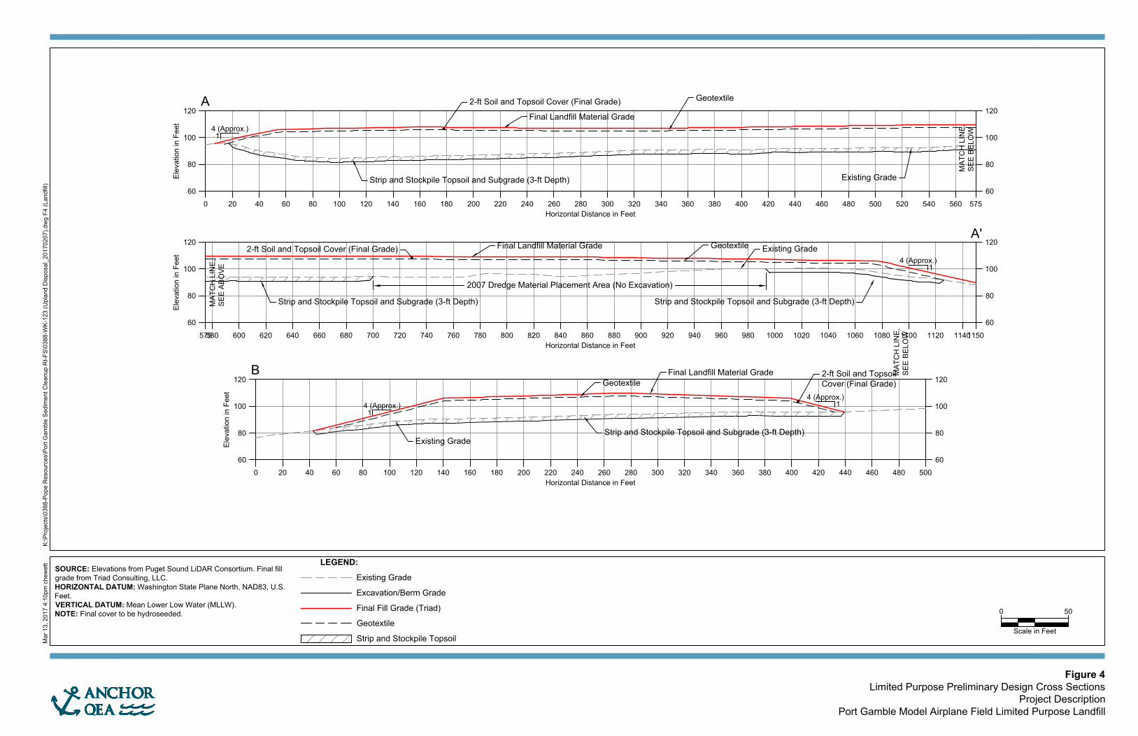
Ele
va
tio
n in
F
ee
t
Horizontal Distance in Feet
60
80
100
120
60
80
100
120
0 20 40 60 80 100 120 140 160 180 200 220 240 260 280 300 320 340 360 380 400 420 440 460 480 500 520 540 560 575
A
Ele
va
tio
n in
F
ee
t
Horizontal Distance in Feet
60
80
100
120
60
80
100
120
0 20 40 60 80 100 120 140 160 180 200 220 240 260 280 300 320 340 360 380 400 420 440 460 480 500
B
4 (Approx.)
1
4 (Approx.)
1
Ele
va
tio
n in
F
ee
t
Horizontal Distance in Feet
60
80
100
120
60
80
100
120
575580 600 620 640 660 680 700 720 740 760 780 800 820 840 860 880 900 920 940 960 980 1000 1020 1040 1060 1080 1100 1120 11401150
A'
Existing Grade
Final Landfill Material Grade
Existing Grade
2-ft Soil and Topsoil Cover (Final Grade)
Geotextile
Final Landfill Material Grade
2-ft Soil and Topsoil
Cover (Final Grade)
Geotextile
Strip and Stockpile Topsoil and Subgrade (3-ft Depth)
Strip and Stockpile Topsoil and Subgrade (3-ft Depth)
Existing Grade
GeotextileFinal Landfill Material Grade
2-ft Soil and Topsoil Cover (Final Grade)
4 (Approx.)
1
4 (Approx.)
1
2007 Dredge Material Placement Area (No Excavation)
Strip and Stockpile Topsoil and Subgrade (3-ft Depth) Strip and Stockpile Topsoil and Subgrade (3-ft Depth)
M
ar 13, 2017 4:10pm
chew
ett K
:\P
rojects\0388-P
ope R
esources\P
ort G
am
ble S
edim
ent C
leanup R
I-F
S\0388-W
K-123 (U
pland D
isposal_20170207).dw
g F
4 (Landfill)
0 50
Scale in Feet
LEGEND:
Existing Grade
Excavation/Berm Grade
Final Fill Grade (Triad)
Geotextile
Strip and Stockpile Topsoil
SOURCE: Elevations from Puget Sound LiDAR Consortium. Final fill
grade from Triad Consulting, LLC.
HORIZONTAL DATUM: Washington State Plane North, NAD83, U.S.
Feet.
VERTICAL DATUM: Mean Lower Low Water (MLLW).
NOTE: Final cover to be hydroseeded.
Figure 4
Limited Purpose Preliminary Design Cross Sections
Project Description
Port Gamble Model Airplane Field Limited Purpose Landfill
MA
TC
H LIN
E,
SE
E B
ELO
W
MA
TC
H LIN
E,
SE
E B
ELO
W
MA
TC
H LIN
E,
SE
E A
BO
VE
SEPA: Port Gamble Model Airplane Field Limited Purpose Landfill Project Pope Resources, LP/OPG Properties, LLC
ATTACHMENT 1
PROJECT DESCRIPTION

Project Description: Port Gamble March 2017 Revision Model Airplane Field Limited Purpose Landfill 1 130388-01.02
PROJECT DESCRIPTION FOR PORT GAMBLE MODEL AIRPLANE FIELD LIMITED PURPOSE LANDFILL
Purpose
The purpose of the Port Gamble Model Airplane Field Limited Purpose Landfill (Landfill) Project (Project) at the Port Gamble Model Airplane Field Site (Site) is to place and permanently contain dredged sediment generated from the Port Gamble Bay cleanup project and excavated nearshore soils generated from the Mill Site habitat restoration project. The Port Gamble Bay cleanup project, including dredging, sorting, processing, characterization and temporary storage of dredged material on the former sawmill, is not part of this Project; cleanup actions were performed under a Consent Decree with the Washington State Department of Ecology consistent with the requirements of the Model Toxics Control Act (MTCA), Chapter 70.105D in the Revised Code of Washington (RCW). Cleanup actions also complied with the Sediment Management Standards (SMS) Chapter 173-204 Washington Administrative Code (WAC). Similarly, Mill Site habitat restoration project soils will be excavated under future habitat restoration permits, and also are not part of this Project.
Up to 150,000 cubic yards (cy) of dredged material will be placed on the Site. Placement of similar dredged materials was performed on the Site in 2007 under a Beneficial Reuse permit.
Location
The Site is located west of State Route (SR) 104 in Port Gamble at approximately 47°50’52”N and 122°35’14”W, as shown on Figure 1. The maximum Project extent is shown on Figure 2, and is confined to parcel identification/ account numbers 072702-1-018-2004, 072702-1-015-2007, 072702-1-016-2006, and 072702-1-017-2005, owned by Pope Resources, LP/Olympic Property Group, LLC (PR/OPG). To comply with applicable regulations, the Project extents are limited by offsets from the parcel
Project Description: Port Gamble March 2017 Revision Model Airplane Field Limited Purpose Landfill 2 130388-01.02
boundaries, the Port Gamble Bay shoreline, and adjacent wetlands. Dredging, transloading, and stockpiling operations in Port Gamble Bay and the adjacent Mill Site are being performed under Ecology oversight and are not part of the Project extent. Dredged material has been placed in temporary piles on the Mill Site for sparging (i.e., rinsing), stockpiling, and soil and leachate verification sampling until final placement in the Landfill.
Background
The preliminary schedule for the project includes preparation of the Landfill location during the summer of 2017 and subsequent filling with sparged dredge material that meets Landfill suitability criteria. Following dredge material placement, the Landfill will be temporarily closed until Mill Site habitat restoration project soils are generated. Alternatively, a portion of the Landfill may be permanently closed following dredge material placement. Following placement of Mill Site habitat restoration project soils, the Landfill will be permanently closed (prior to summer of 2022). The Project will be designed and constructed under the requirements of WAC 173-350-400, Kitsap County Board of Health Ordinance Number 2010-1, and Kitsap County Site Development Application Permit requirements. The Kitsap County Board of Health Limited Purpose Landfill Application develops and documents the design basis for all Project elements. Other anticipated permitting requirements include State Environmental Policy Act (SEPA) Mitigated Determination of Nonsignificance, Kitsap County Site Development Activity Permit, Kitsap County Health District Solid Waste Permit, and National Pollutant Discharge Elimination System (NPDES) Construction General Permit.
Project Setting
The entire Site is approximately 18 acres, primarily consisting of a maintained grass field situated between SR 104 to the east, and wetlands to the north, northeast, west, and southwest (Figure 2). The Landfill area will be approximately 8.4 acres to

Project Description: Port Gamble March 2017 Revision Model Airplane Field Limited Purpose Landfill 3 130388-01.02
accommodate 150,000 cy of dredge material. The Site is used for recreational purposes with a gravel access road and parking area, a mowed model airplane runway, and a trail leading north and south from the Site. The Site uses will not be changed as a result of implementing the Project. Recreational trails may be temporarily blocked or closed during Landfill construction (for safety considerations), and public access and parking will be closed during construction. Alternatively, trails may be relocated to minimize construction impacts. Port Gamble Bay is to the east of SR 104 and is approximately 400 feet from the edge of the Site. Wetlands and associated buffers border the Site to the north, northeast, west, and southwest and were delineated in a 2013 survey by GeoEngineers (Figure 2) and verified by Anchor QEA wetland ecologists in 2015 (Anchor QEA 2015) and reconfirmed in 2017. The Site ranges in elevation from approximately 72 to 100 feet mean lower low water (MLLW) and grades gently to the east, west, south, and north. The northern tip of the Site grades more steeply toward adjacent wetlands. There are no structures located on the Site. The geological and hydrogeological conditions of the Site were evaluated with a soil boring investigation by Anchor QEA in 2015. The Site is characterized by a thin layer of topsoil, underlain by a glacial till unit greater than 75 feet below ground surface. No significant groundwater-bearing units have been identified within the till unit, however, thin water-bearing sand lenses were identified 16 feet and 61 feet below ground surface in two separate soil borings on the south half of the Site. These sand lenses represent discrete areas of perched water, consistent with previous characterizations of Vashon Drift till unit in Kitsap County.
Proposed Project
The Project will consist of the following: 1) surface grading of the Site in preparation for dredge material placement; 2) placement of Port Gamble Bay dredged material meeting suitability criteria, followed by temporary Landfill closure (or permanent closure of a portion of the Landfill); 3) placement of Mill Site habitat restoration project soil meeting suitability criteria; 4) final cover and final Landfill closure; and 5)

Project Description: Port Gamble March 2017 Revision Model Airplane Field Limited Purpose Landfill 4 130388-01.02
monitoring (visual inspection, groundwater, and methane). The following paragraphs summarize these project phases. All design elements will comply with the requirements of WAC 173-350-400, Kitsap County Board of Health Ordnance Number 2010-1, Kitsap County Site Development Application Permit, and all applicable environmental standards. Grading of the Site will consist of removal of topsoil from the Landfill area; however, topsoil from dredged material placed in 2007 (1.5 acres) will be marked during site preparation work so that the material remains in place and is not used as cover material during final closure. The topsoil will be stockpiled on the Site for use during final closure. The perimeter of the Landfill will include appropriate best management practices (BMPs) to minimize the potential for erosion during construction activities. As noted above, Recreational trails may be temporarily blocked or closed during Landfill construction (for safety considerations), and public access and parking will be closed during construction. Alternatively, trails may be relocated to minimize construction impacts. The Landfill will not require a liner or leachate collection because dredge material placed will be protective of groundwater quality standards, as verified by sampling of stockpiled material. Moreover, additional protectiveness of the groundwater resource will be achieved because dredged material will be placed in the unsaturated groundwater zone above a thick (more than 175-foot) low-permeability till and regional aquifer confining unit. In addition, a groundwater monitoring network will be installed to verify groundwater protection. Following subgrade preparation, dredged material will be placed. Following sparging at the former sawmill, dredged material will be transported to the Site by truck and placed in the Landfill. Material will be placed in lifts and compacted with standard earthwork equipment. When all dredged material from Port Gamble Bay is placed, a temporary cover will be installed to contain the dredged material and to manage stormwater appropriately. Alternatively, a portion of the Landfill could be covered and permanently closed after dredged material is placed. The final project phasing

Project Description: Port Gamble March 2017 Revision Model Airplane Field Limited Purpose Landfill 5 130388-01.02
and method of temporary closure will be specified by the project engineer. When Mill Site habitat restoration material is ready for placement, placement of dredged material will resume. When all material has been placed, the Landfill will be permanently closed. The Project will raise the grade of the Site from 0 to 25 feet above current ground surface depending on location (see Figures 3 and 4). Following final grading of dredged material, the material will be covered with an identification layer (e.g., geotextile), and 2 feet of clean cover soil. The surface will be hydroseeded to restore the Landfill to pre-construction conditions. The final grade will be geotechnically stable (slope no steeper than 3H:1V based on geotechnical evaluations). The minimum grade will be 2% for stormwater drainage, and will result in stormwater drainage patterns similar to those in pre-construction conditions. Following closure, the Site will be monitored in accordance with regulations and the final Project permit conditions. The long-term stability of the Landfill will be evaluated by physical inspection. Groundwater monitoring will also be performed to verify groundwater protection.
Construction Methods
The Project will be constructed using standard earthwork equipment, such as back hoes, excavators, and dump trucks, to place and grade the material. Dump trucks will place dredge material directly onto the placement area. After dumping, dredged material will be spread into lifts for compaction. Placement and compaction of dredged sediment and cover material will be performed under applicable Washington State Department of Transportation (WSDOT) Standard Specifications for construction of embankments. Work will proceed from lower topographic elevations to higher topographic elevations. During construction and operation, construction stormwater will be managed with BMPs outlined below.

Project Description: Port Gamble March 2017 Revision Model Airplane Field Limited Purpose Landfill 6 130388-01.02
Following placement, an identification layer (e.g., geotextile) will be installed on top of the dredged material in accordance with the WSDOT and the manufacturer’s specifications. Geotextile will likely be unrolled by hand with construction equipment and temporarily anchored during cover placement. Cover placement and final compaction will be performed with earth moving equipment. Hydroseeding will be performed using trucks.
Best Management Practices
Temporary facilities to be installed prior to and maintained during construction include the following:
1. Stormwater generated during construction will be temporarily stored and/or treated by one or more of the following methods from the Kitsap County Stormwater Design Manual standard specifications. The final suite of BMPs will be selected during the final design to follow Kitsap County Standards based on the final volume of dredged sediment placed in the Landfill: a. Covering placed material with plastic sheeting to reduce contact with
stormwater b. A silt fence or fences anchored to contain placed dredge material and silt
generated in the uplands c. Existing vegetated buffers used to collect sediment in sheet flows d. Surface-roughening to decrease runoff velocities and increase infiltration e. Straw waddles, hay bales, or swales used to reduce suspended sediment f. A containment berm constructed to temporarily store stormwater
2. Construction materials will not be stored where runoff can cause materials to enter surface waters.
3. A Spill Prevention and Emergency Cleanup Plan (SPECP) will be prepared prior to construction and used for the duration of the project.
4. Final Temporary Erosion and Sediment Control (TESC) Plans will be completed prior to construction and used for the duration of the project.

Project Description: Port Gamble March 2017 Revision Model Airplane Field Limited Purpose Landfill 7 130388-01.02
Final stabilization of the Landfill include installation of the following:
• Material will be covered with an identification layer (e.g., geotextile) and 2 feet of clean cover soil.
• Topsoil will be hydroseeded to restore the Landfill to pre-construction conditions.
Periodic inspection and maintenance activities (if necessary) specified in a post-closure plan will ensure that the Landfill remains stable over the long term.
Project Timing
As noted above, the anticipated schedule for the Project includes preparation of the Landfill location during the summer of 2017 and subsequent filling with dredged sediment, followed by temporary closure. Alternatively, a portion of the Landfill may be permanently closed following dredge material placement. Additional Mill Site habitat restoration project soils will be placed in the MAF before 2022, followed by cover placement. The Landfill is anticipated to be closed by the summer of 2022. Long-term monitoring will commence and is expected to continue for approximately 20 years. Site use will not be effected by the Landfill.

FIGURES

PORTGAMBLE
BAY
%
Location ofLocation ofFormer SawmillFormer Sawmill
(Mill Site)(Mill Site)
PointPointJuliaJulia
UV104
HOODCANAL
%
Model AirplaneModel AirplaneField SiteField Site
%
Footprint of LimitedFootprint of LimitedPurpose LandfillPurpose Landfill
%
Approximate Location ofApproximate Location ofUSGS (Welch et, al.) TransectUSGS (Welch et, al.) Transect
27N/02E-06Q0127N/02E-06Q01
27N/02E-18H0127N/02E-18H01
\\orca
s\GIS\
Jobs
\Pope
Reso
urces
_038
8\Port
Gamb
le\Ma
ps\R
eport
s\Mod
el_Air
plane
\AQ_F
ig1_S
iteVic
inityL
PLAp
p.mxd
eive
rson
2/13/2
017
3:07:4
7 PM
0 1,000 2,000 3,000 4,000Feet
[
LEGEND
Figure 1Site Vicinity Map
Limited Purpose Landfill ApplicationPort Gamble Model Airplane Field Limited Purpose Landfill
PROJECTVICINITY

80
9
0
7
0
6
0
7
0
7
0
5
0
3
0
1
0
60
7
0
8
0
90
8
0
7
0
7
0
5
0
30 1
0
H
IG
H
W
A
Y
1
0
4
8
5
9
0
95
100
1
0
0
1
0
5
1
0
5
106
107
107
M
ar 13, 2017 4:10pm
chew
ett K
:\P
rojects\0388-P
ope R
esources\P
ort G
am
ble S
edim
ent C
leanup R
I-F
S\0388-W
K-123 (U
pland D
isposal_20170207).dw
g F
2 (Landfill)
0
Scale in Feet
150
LEGEND:
Contours, 2' and 10'
Mean Higher High Water (Elev. 8.18' NAVD88)
200' Mean Higher High Water Offset
Existing Wetland (GeoEngineers)
150' Wetland Buffer (GeoEngineers)
Current Parcel Boundary (See Note)
Applicable 100' Parcel
Boundary Offset
Proposed Location of
Limited Purpose Landfill
Site Extent
Figure 2
Site Features
Project Description
Port Gamble Model Airplane Field Limited Purpose Landfill
SOURCE: Elevations from Puget Sound LiDAR Consortium. Aerial image
from ESRI. Existing wetland and offset information from GeoEngineers.
Parcels from Kitsap County GIS.
HORIZONTAL DATUM: Washington State Plane North, NAD83, U.S. Feet.
VERTICAL DATUM: North American Vertical Datum of 1988 (NAVD88).
NOTE: A boundary line adjustment will be performed to place the Landfill
on a single parcel.

80
9
0
7
0
6
0
7
0
7
0
5
0
3
0
1
0
60
7
0
8
0
90
8
0
7
0
7
0
5
0
30 1
0
AA
'
B'B
H
IG
H
W
A
Y
1
0
4
8
5
9
0
95
100
1
0
0
1
0
5
1
0
5
106
107
107
M
ar 13, 2017 4:10pm
chew
ett K
:\P
rojects\0388-P
ope R
esources\P
ort G
am
ble S
edim
ent C
leanup R
I-F
S\0388-W
K-123 (U
pland D
isposal_20170207).dw
g F
3 (Landfill)
0
Scale in Feet
150
Figure 3
Limited Purpose Preliminary Design Plan
Project Description
Port Gamble Model Airplane Field Limited Purpose Landfill
LEGEND:
Contours, 2' and 10'
Proposed Contours, 1' and 5'
Mean Higher High Water (Elev. 8.18' NAVD88)
200' Mean Higher High Water Offset
Existing Wetland (GeoEngineers)
150' Wetland Buffer (GeoEngineers)
Current Parcel Boundary (See Note)
Applicable 100' Parcel
Boundary Offset
Proposed Location of
Limited Purpose Landfill
Approximate Extent of 2007 Dredge
Material Placement (No Topsoil Removal in this Area)
SOURCE: Elevations from Puget Sound LiDAR Consortium. Aerial image
from ESRI. Existing wetland and offset information from GeoEngineers.
Parcels from Kitsap County GIS.
HORIZONTAL DATUM: Washington State Plane North, NAD83, U.S. Feet.
VERTICAL DATUM: North American Vertical Datum of 1988 (NAVD88).
NOTE: A boundary line adjustment will be performed to place the Landfill
on a single parcel.

Ele
va
tio
n in
F
ee
t
Horizontal Distance in Feet
60
80
100
120
60
80
100
120
0 20 40 60 80 100 120 140 160 180 200 220 240 260 280 300 320 340 360 380 400 420 440 460 480 500 520 540 560 575
A
Ele
va
tio
n in
F
ee
t
Horizontal Distance in Feet
60
80
100
120
60
80
100
120
0 20 40 60 80 100 120 140 160 180 200 220 240 260 280 300 320 340 360 380 400 420 440 460 480 500
B
4 (Approx.)
1
4 (Approx.)
1
Ele
va
tio
n in
F
ee
t
Horizontal Distance in Feet
60
80
100
120
60
80
100
120
575580 600 620 640 660 680 700 720 740 760 780 800 820 840 860 880 900 920 940 960 980 1000 1020 1040 1060 1080 1100 1120 11401150
A'
Existing Grade
Final Landfill Material Grade
Existing Grade
2-ft Soil and Topsoil Cover (Final Grade)
Geotextile
Final Landfill Material Grade
2-ft Soil and Topsoil
Cover (Final Grade)
Geotextile
Strip and Stockpile Topsoil and Subgrade (3-ft Depth)
Strip and Stockpile Topsoil and Subgrade (3-ft Depth)
Existing Grade
GeotextileFinal Landfill Material Grade
2-ft Soil and Topsoil Cover (Final Grade)
4 (Approx.)
1
4 (Approx.)
1
2007 Dredge Material Placement Area (No Excavation)
Strip and Stockpile Topsoil and Subgrade (3-ft Depth) Strip and Stockpile Topsoil and Subgrade (3-ft Depth)
M
ar 13, 2017 4:10pm
chew
ett K
:\P
rojects\0388-P
ope R
esources\P
ort G
am
ble S
edim
ent C
leanup R
I-F
S\0388-W
K-123 (U
pland D
isposal_20170207).dw
g F
4 (Landfill)
0 50
Scale in Feet
LEGEND:
Existing Grade
Excavation/Berm Grade
Final Fill Grade (Triad)
Geotextile
Strip and Stockpile Topsoil
SOURCE: Elevations from Puget Sound LiDAR Consortium. Final fill
grade from Triad Consulting, LLC.
HORIZONTAL DATUM: Washington State Plane North, NAD83, U.S.
Feet.
VERTICAL DATUM: Mean Lower Low Water (MLLW).
NOTE: Final cover to be hydroseeded.
Figure 4
Limited Purpose Preliminary Design Cross Sections
Project Description
Port Gamble Model Airplane Field Limited Purpose Landfill
MA
TC
H LIN
E,
SE
E B
ELO
W
MA
TC
H LIN
E,
SE
E B
ELO
W
MA
TC
H LIN
E,
SE
E A
BO
VE


![WAC 173-350-500 Groundwater monitoring. Groundwater ...WAC (5/6/2015 11:58 AM) [ 1 ] NOT FOR FILING WAC 173-350-500 Groundwater monitoring. (1) Groundwater monitoring– Professioanl](https://img.pdfslide.us/doc/110x75/5ed964b1f59b0f56f45f68c7/wac-173-350-500-groundwater-monitoring-groundwater-wac-562015-1158-am.jpg)