Embed Size (px)
Citation preview

Scenario 01 ML082830898.doc Rev.1
Appendix D, Rev. 9 Scenario Outline Form ES-D-1
Facility: Diablo Canyon Scenario No.: 1 Op-Test No.: L061-1
Examiners: Operators:
Initial Conditions: 100% Power, MOL, 782 ppm CB Turnover: PRA Status: Green. Protected Equipment – Train B, Buses H& G, Prot. Sets II, III, IV. Sub-Cooled Margin Monitor train B OOS due to PT-403 failure. Swap CCW pps 1-1 and 1-3. U-2 at 100% power.
Event No.
Malf. No. Event Type*
Event Description and Time Line
1 N Swap CCW Pump 1-1 and 1-3
2 Pmp cnd10 R Heater 2 Drip Pump trips on over current (programmed ramp to 770 MWE at 40 MW/min).
3 Pmp asw1 C Auxiliary Saltwater pump 11 trips on over current 3 minutes after generator < 771 MW. (TS 3.7.8.A)
4 xmt tur2 I PT-505 fails low 10 minutes after ASW pp 12 is started. (TS 3.3.1.T)
5 mal sei1 M 0.28g earthquake 10 minutes after PT-505 failure.
6 mal rcs1 M DBA LOCA after earthquake.
7 mal ppl1b C Phase A train B fails to actuate on SI.
8 bkr eps 11 C Auxiliary Saltwater Pump 1-2 fails to restart on SI.
*(N)ormal, (R)eactivity, (I)nstrument, (C)omponent, (M)ajor
Scenario 01 ML082830898.doc Rev.1
Appendix D, Rev. 9 Required Operator Actions Form ES-D-2
Op-Test No.: L061-1 Scenario No.: 1 Event No.: 1 Page 1 of 7
Event Description: Swap CCW Pumps 1-1 and 1-3
Time Position Applicant’s Actions or Behavior
SRO Briefs crew on swap of CCW pumps per OP F-2:II.
BOP Starts CCW Pump 1-3 & secures CCW Pump 1-1.
• Checks the idle pump is available for normal system operation.
• Selects the CCW Pump 1-3 Standby selector switch to manual.
• Starts CCW Pump 1-3, verifies normal running amps and flow.
• Places CCW Pump 1-1 control switch in stop.
• Verifies CCW header flow returns to normal.
• Places idle CCW Pump Standby selector switch in auto.

Scenario 01 ML082830898.doc Rev.1
Appendix D, Rev. 9 Required Operator Actions Form ES-D-2
Op-Test No.: L061-1 Scenario No.: 1 Event No.: 2 Page 2 of 7
Event Description: Heater 2 Drain Pump Trip
Time Position Applicant’s Actions or Behavior
RO Acknowledge alarm PK10-14, Input 636, Heater 2 Drain Pump OC Trip.
BOP Diagnose Heater 2 Drain Pump tripped on Over Current.
SRO Responds per Annunciator Response Procedure PK10-14.
• Transitions to AP-15, Section C, based on Heater 2 Drain Pump Trip.
SRO Enters AP-15 “Loss of Feedwater Flow”, Section C “Heater 2 Drain Pump Trip.”
• Verifies MFP suction pressure is greater than 260 psig.
• Verifies Programmed Ramp is occurring
• Checks MFP suction pressure is greater than 260 pisg.
BOP Check MFP Suction Pressure Greater Than 260 psig.
RO Verify Programmed Ramp Occurring.
• DEH MW Feedback in service, Target set to 770 MW, Ramp Rate at 40 Mw/Min.
SRO Transitions to Section D, Step 2 of AP-15, Condensate/Booster Set Trip.
• Verifies MFP suction pressure is greater than 260 psig.
• Determines transition to AP-25 “Rapid Load Reduction” is required
SRO Enters AP-25 “Rapid Load Reduction or Shutdown.
• Verifies Control Rods inserting in Auto.
• Verifies Pressurizer backup heaters – ON.
• Verifies Charging system operation is adequate.
• Verifies Digital Feedwater Controls controlling SG Levels in Auto.
• Determine Requirements and Direct Boration of RCS. (Based on Reactivity Handbook Guidance – 167 gallons BA with in 2 hours)
RO Verify Control Rods inserting in Auto in response to Ramp.
RO Verifies Backup Pressurizer Heater groups are ON.
BOP/RO Verify Charging System operation is adequate.
• Controls charging in Manual as needed to prevent Letdown system flashing.
RO Performs Boration of RCS using Boration Checklist and Makeup controller.
• Set Target Batch on flow controller (as determined by SRO)
• Verify Boric Acid Flow rate set to desired flow.
SRO Responds per Annunciator Response Procedure 03-14, Rod LO LO Insertion limit.
• Directs RO implement AP-6, “Emergency Boration.”
RO Performs Emergency Boration Per AP-6, “Emergency Boration”
Scenario 01 ML082830898.doc Rev.1
Appendix D, Rev. 9 Required Operator Actions Form ES-D-2
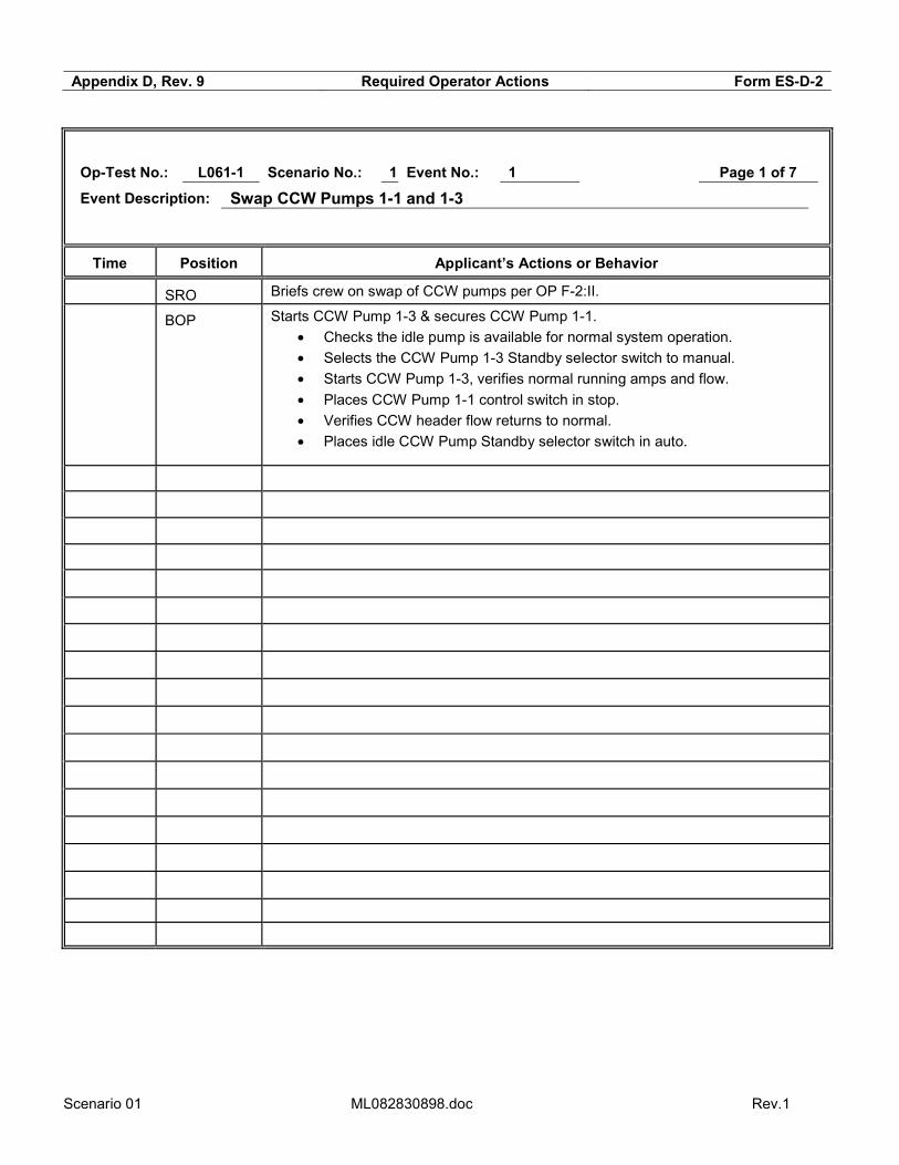
Op-Test No.: L061-1 Scenario No.: 1 Event No.: 3 Page 3 of 7
Event Description: ASW Pump 11 Over Current Trip
Time Position Applicant’s Actions or Behavior
CO Acknowledge alarm PK 01-03, Input 427, Aux Salt Water Pump OC Trip.
CO/BOP Diagnose Aux Salt Water Pump 1-1 tripped on Over Current.
SRO Responds per Annunciator Response Procedure PK 01-03 (May refer to OP AP-10).
• Directs Starting of Standby ASW Pump 1-2.
• Verifies CCW-ASW HX DP is within limits.
• Direct continuous chlorination to be secured.
• Dispatch operator to investigate failure.
• Directs Maintenance to investigate failure of ASW pump 1-1
• Refers to Tech Spec 3.7.8 A “ASW System” (Determines 72 Hr action statement applies with 1 train inoperable)
BOP Starts ASW Pump 1-2
• Selects manual on auto/manual selector switch.
• Starts ASW Pump 1-2, verifies normal running amps.
• Checks ASW/CCW systems are intact and CCW HX is not fouled.

Scenario 01 ML082830898.doc Rev.1
Appendix D, Rev. 9 Required Operator Actions Form ES-D-2
Op-Test No.: L061-1 Scenario No.: 1 Event No.: 4 Page 4 of 7
Event Description: PT-505 fails low
Time Position Applicant’s Actions or Behavior
RO/BOP Diagnose failure (LOW) of PT-505, 1st Stage Impulse pressure.
SRO Direct RO to place Rod Control in MANUAL
RO Places Rod Control in MANUAL
SRO Enters AP-5, “Malfunction of Eagle 21 Protection or Control Channel.”
• Verifies Primary and Secondary Control Systems are controlling properly in AUTO (Step to place rods in manual will be completed prior to this step)
• Directs RO to recover temperature with rod motion in manual (Reactivity Brief should include discussion on 3 steps pull and wait).
• Determines failure not to be related to Eagle 21.
• Determines alternate channel is not available for selection.
• Determines redundant recorder is not available. (Tref will have to be manually determined)
• Determines LTB and Steam Dumps are not actuated.
• Notifies Maintenance to investigate
• Uses attachment 4.1 determine affected control systems
• Directs Steam Dumps be placed in Steam Pressure Mode.
• Refers to Tech Spec 3.3.1.T (verify P-13 within 1 hour and & ECG 4.1 (AMSAC)
RO Restores Tave to Tref using manual control rods – observes 3 steps pull and wait requirement.
BOP Verify LTB and Steam Dumps not Actuated.
BOP Places Steam Dumps in Steam Pressure Mode, Per STP I-4-P505.
• Places HC-507 in Manual
• Places Train A & B Steam Dump Control Bypass Selector Switch in OFF/RESET
• Places Steam Dump Mode select to Steam Pressure Mode
• Verify UI-500 indicates 0%
• Places Train A & B Steam Dump Control Bypass Selector Switch in ON

Scenario 01 ML082830898.doc Rev.1
Appendix D, Rev. 9 Required Operator Actions Form ES-D-2
Op-Test No.: L061-1 Scenario No.: 1 Event No.: 5 Page 5 of 7
Event Description: Seismic Event & DBA LOCA
Time Position Applicant’s Actions or Behavior
RO/BOP/
SRO
Diagnose seismic event, based on ground motion and seismic alarms.
RO/BOP/
SRO
Diagnose Automatic Reactor Trip and Safety Injection.
RO/BOP Perform immediate actions:
• Verify Reactor Tripped.
• Verify Turbine Tripped.
• Verify Vital 4 KV Buses Energized.
• Check SI Actuated.
SRO Enter E-0, “Reactor Trip or Safety Injection”
• Verify completion of Immediate Actions.
• Recognizes RCP trip criteria met, directs RCPs to be tripped. **
• Direct implementation of Appendix E.
• Checks status of AFW flows, direct throttling to minimum required flow.
• Determines RCS is not intact and recognizes procedure transition criteria met for EOP E-1, “Loss of Reactor of Secondary Coolant”.
• Directs placing 2nd CCW Heat Exchangers in-service.
• Implements F-0, monitors CSFSTs – No Challenges
• Transitions to E-1, “Loss of Reactor of Secondary Coolant”.
RO Implements Appendix E
• Diagnose Partial Phase A
• Performs verification steps in Appendix E (See events 6 & 7 for actions)
• Reports status to SRO at step 9 and 18
BOP Throttles AFW flow as directed by SRO.
• Closes TD AFW pump LCVs.
• Throttles MD AFW LCVs.
RO/BOP Trips Reactor Coolant pumps**
RO/BOP Places 2nd CCW Heat Exchanger in-service – note: only one ASW pump is available.
** Critical Task

Scenario 01 ML082830898.doc Rev.1
Appendix D, Rev. 9 Required Operator Actions Form ES-D-2
Op-Test No.: L061-1 Scenario No.: 1 Event No.: 5 Page 6 of 7
Event Description: DBA LOCA
Time Position Applicant’s Actions or Behavior
SRO Conducts Procedure Transition Brief for E-1, “Loss of Reactor of Secondary Coolant”.
• Plant Status
• Major Actions
• Foldout Page Assignments
• Questions
SRO Enter E-1, “Loss of Reactor of Secondary Coolant”.
• Performs verification steps
• May transition to FR-Z.2, “Response to Containment Flooding.” and/or FR-P.1, “Response to Imminent Pressurized Thermal Shock” based on scenario timing.
• Transitions to E-1.3 when RWST level reaches 33%
RO/BOP Perform verification steps in E-1 as directed by SRO.
RO/BOP Report status of RHR Pumps (OFF) when RWST level reaches 33%
SRO Enter E-1.3, “Transfer to Cold Leg Recirculation” **
• Direct Reset of SI & Phase A and B
• Check Status of ECCS Pumps – Direct securing 2 CFCUs.
• Dispatch operator to close breakers
• Direct valve manipulations to place RHR in service from the recirc sump.
• Determines that only 1 train of RHR can be placed in service, only 1 ASW pp available.
RO Reset SI, Phase A and Phase B
RO Secure 2 CFCUs as directed by SRO
RO/BOP Perform the valve manipulations to place RHR in service from the Recirc Sump. **
• Close 8716 A & B – RHR Pump Discharge Crossties.
• Close 8700 A & B – RHR RHR Suction Isolation valves.
• Cut in Series contactor and Open 8982B – Pump 2 Sump suction.
• Open FCV-364 – CCW to RHR Heat Exchanger No. 2.
• Start RHR Pump 1-2.
• Cut in Series contactor and Close 8974 A & B – SI pump Recirc.
• Open 8804 – RHR discharge to SI Pump 1-2.
• Close 8105 and 8106 – CCP Recirculation isolation.
• Open 8807 A & B – RHR Hx No. 1 to SI pump 1-1.
• Cut in Series contactor and open 8982A – Pump 1 Sump suction.
• Open FCV-365 – CCW to RHR Heat Exchanger No. 1.
• Close 8805 A & B, 8976 and 8980, suctions from RWST.
Terminate after cold leg recirculation is established
** Critical Task

Scenario 01 ML082830898.doc Rev.1
Appendix D, Rev. 9 Required Operator Actions Form ES-D-2
Op-Test No.: L061-1 Scenario No.: 1 Event No.: 7 & 8 Page 7 of 7
Event Description: Phase A Train B Fails/ ASW Pump 1-2 fails to restart
Time Position Applicant’s Actions or Behavior
CO/BOP Determines Train B of Phase A Containment Isolation is not met.
Takes action to place the following valves to the closed position:
• 9355B – PZR Liquid Sample OC
• 9356B – RCS Sample OC
• 8880 – N2 supply to Accumulators
• 8152 – Letdown Isolation
• 8100 – RCP Seal Return
• 8029 – Containment Primary Water
• 8045 – PRT N2 supply
• 633 – Containment Fire Water Supply
• 584 – Instrument Air Supply
• Rad Waste Isolation Train B
CO/BOP Starts ASW Pump 1-2 **
** Critical Task

Scenario 01 ML082830898.doc Rev.1
MAJOR EVENT SUMMARY AND SCENARIO OBJECTIVES
A. Crew will swap CCW pumps, CCW pump 1-3 will be started and CCW Pump 1-1 will be
secured using, OP F-2:II, CCW System – Changing Over Pumps and Common Components.
B. Heater 2 Drip Pump trips on over current. Programmed ramp to 770 MWE at 40 MW/min.
Crew responds per AP-15 “Loss of Feedwater Flow” and AP-25 “Rapid Load Reduction or
Shutdown.”
C. Auxiliary Saltwater pump 11 trips on over current. Crew responds per AR PK 01-03 “Aux Salt
Water Pumps” and verifies ASW pp 12 in service.
D. PT-505 fails low, causing inward rod motion. Rod are taken to manual, and crew enters AP-5
“Malfunction of Eagle 21 Protection or Control Channel” to address instrument failure.
E. Earthquake at 0.28g causes DBA LOCA. Crew enters E-0 “Reactor Trip or Safety Injection”
on automatic Reactor Trip and Safety Injection.
F. On the Safety Injection, Train B of Phase A Containment Isolation does not actuate, and
isolation must be done via manual operator actions.
G. On the Safety Injection, ASW pump 1-2 fails to start, and must be restarted manually.
H. Crew transitions from E-0 to E-1 “Loss of Reactor or Secondary Coolant” and performs
verification steps.
I. Crew may go to FR Z.2 “Response to Containment Flooding” due to Hi Level in the
Recirculation Sump, crew will transfer out of FR Z.2 at step 1, monitor level and return to
procedure and step in effect.
J. Crew will go to E-1.3 “Transfer to Cold Leg Recirculation”, at 33% RWST level, and transfer
to cold leg recirculation, only one train of RHR is available due to failure of ASW pp 1-1.
K. Scenario is terminated after cold leg recirculation is aligned.
Scenario 01 ML082830898.doc Rev.1
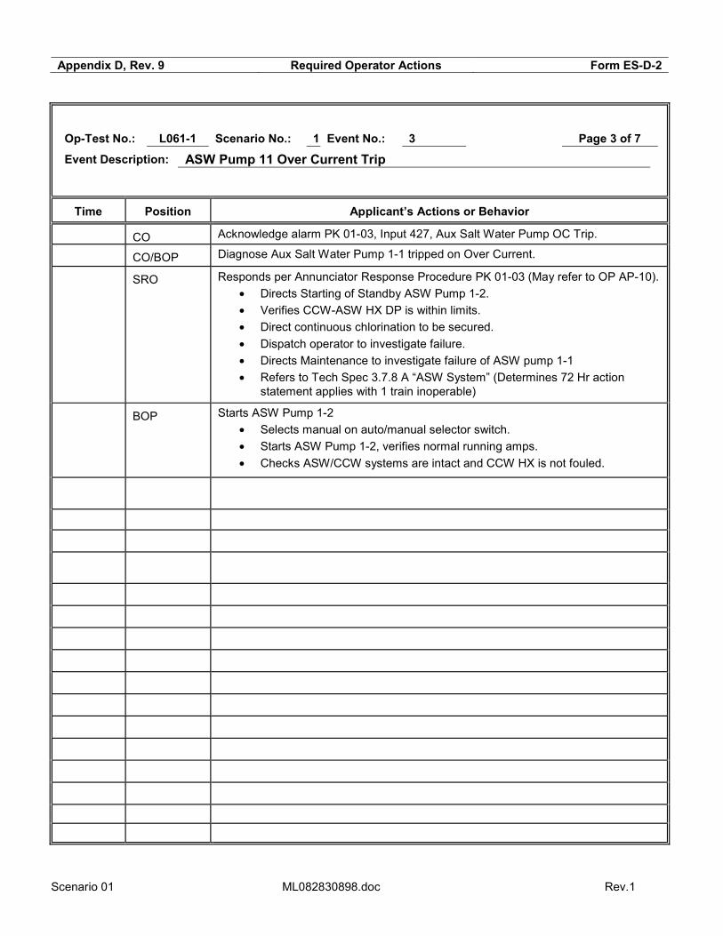
ATTACHMENT 1 - SIMULATOR SET-UP
TIME LINE CONSOLE ENTRY SYMPTOMS/CUES/DESCRIPTION
Setup Simulator per Checklist
Init 510 100% power, MOL, CB = 782
• Integrators: BA - 0 and PW – 40 • Tags: OOS on SCMM & PT-403 on VB2
Setup Drill 81 Reset normal engineering values
Setup Drill 41
Drill 79
Clears Subcooled Margin Monitor Train B
Limit NI response on a DBA LOCA
CONTROL BOARD SETUP Copies of commonly used forms and procedures are available. Any tags are placed/removed as necessary. Primary integrator =40 gal, Boron = 0 gal. Record PPC MAX (BOL = 99.8, MOL = 100.0, EOL = 100.2) on CC2 lamicoid The plant Abnormal Status Board is updated with last CCP CB near 782 and current date. Circuit breaker flags are correct. Equipment status lamicoids are correct:
B.A. XFER PP SUPPLYING BLENDER - BA Pp 1-2
SUPPLYING IN-SERVICE SCW HX - CWP 1-1
AUTO RECLOSE FEATURE CUTIN ON THIS CWP - CWP 1-1
SELECTED TO BUS 2F - Cont. Rm. Vent Train 1 Bus F
SELECTED TO BUS 1H - Cont. Rm. Vent Train 1 Bus H
The proper Delta-I curve and Reactivity Handbook for the simulator INIT are in place The Rod Step Counters indicate correctly. PPC Setup:
o QP TAVG, ALM/MODE-1, QP CHARGING, BIG U1169 o RBU is updated. o PEN running. o R2B blowdown flows at 90 gpm.
o Reactor trip status correct 1(Pg 2 of Group display Mode-1). o Operational mode correct for current conditions.2
o Delta-I target slope matches Delta-I curve (DeltaI menu →Option 5, constants K0500-0503=100% power target DeltaI / 100)
SPDS (screens and time updating), A screen “RM”, B screen “SPDS”. The chart recorders are operating properly, and advanced. All typewriters are on, with adequate paper/ribbon/etc., and are in the “ON LINE” status. The Annunciator Horn is on (BELL ON). Sound Effects are on (SOUND ON). The video and audio systems are SECURED. Communications systems are turned on and functional.
1 If not correct, place PPC display in ovrd mode, and press add/omit key. Type point Y0006D and select F2 to restore processing. This should update the trip breaker status. 2 Allow about ten minutes for the PPC to automatically update the plant mode. If still not correct, place PPC display in ovrd mode, and type APMC. Follow menu to manually override to correct mode.

Scenario 01 ML082830898.doc Rev.1
TIMELINE AND INSTRUCTOR ACTIONS FOR SIMULATION X = manual entry required
X 0 min DRILL 6603 After SRO reports the crew has taken the watch, load session MALS, OVRs, etc. by DRILL FILE or MANUALLY (below)
0 min pmp asw2 1,0,0,0,d,0 Block auto start of ASW pp 12
0 min bkr eps11 3,0,0,0,d,0 Blocks 52-HG-14 from closing S/U to bus G fdr
3 min pmp cnd10 6,3,300,180,d,0 Heater 2 Drain Tank PP 11 OC trip
X When requested Report Htr 2 Drain pp motor has burnt smell, A & C phase OC relays dropped at breaker
< 771 MW pmp asw1 6,6,5,180,c,smss.lt.771 ASW pp 1-1 trips on OC
X When requested Ser 0425 act,1,0,0,d,55 Brings in door alarms for ASW Pps during inspections.
X When requested Report ASW pp 11 motor is hot to touch, B phase OC relay dropped at bkr
10 min after ASW pp 12 started
xmt tur2 2,0,0,600,c,xv1o243r PT-505 fails low
10 minutes after PT-505 failure
mal sei1 act 0.28,10,480,c,jmlsyd2 0.28 g earthquake
On Seismic mal rcs1 act 3,4,15,c,jmlsei1 DBA LOCA on loop 4
mal ppl1b act 2,0,0,d,0 Cnm Iso Phase A train B fails to actuate
On reactor trip PA Drill 32 NO action on a trip
X When requested dsc sis14 act,1,0,0,d,0 dsc rhr4 act,1,0,0,d,0
opens 8976 breaker
opens 8980 breaker

Scenario 01 ML082830898.doc Rev.1
DIABLO CANYON POWER PLANT
OPERATIONS SHIFT LOG UNIT 1
OPERATING MODE: 1 POWER LEVEL: 100 % GROSS GENERATION: 1198 MWe NET GENERATION 1155 MWe DAYS AT POWER: 120
Shift Manager Turnover
PRA RISK STATUS NEXT SHIFT: GREEN -
PROTECTED EQUIPMENT: Train B, Buses H & G, Prot. Sets II,III,IV
HOMELAND SECURITY THREAT LEVEL: YELLOW GRID STATUS NEXT SHIFT: Normal AVERAGE RCS CALCULATED LEAKRATE: 0.05 gpm
URGENT WORK:
* None
ACTIVE SHUTDOWN TECH SPECS / ECGS:
* PT-403 - T.S 3.3.3.A - 30 days; due in 29 days, 22 hours. .
TURNOVER ITEMS:
* PT-403 failed low 2 hours ago. The problem has been identified and it is expected to be returned to service in 8 hours. * Swap CCW Pump 1-1 and 1-3 immediately after assuming the watch, to equalize run times.
OPERABILITY ITEMS:
* None
PRIORITY ITEMS FOR NEXT SHIFT:
* Repair of PT-403.
ANNUNCIATORS IN ALARM * PK 05-07, PK 05-09

Scenario 01 ML082830898.doc Rev.1
SHIFT FOREMAN TURNOVER
COMMENTS:
1. Reactivity management:
a. Time in core life: MOL
b. Power History: 100%
c. Boron concentration is 782 ppm from a sample taken 4 hours ago.
d. Diluting 40 gallons every 2 hours.
e. ΔI is stable
2. No one is in Containment, no entries are expected
3. U-2 is operating at 100% power COMPENSATORY MEASURES:
None
CONTROL ROOM ABNORMAL STATUS
See Abnormal Status Board.

Scenario 02 ML082830898.doc
Appendix D, Rev. 9 Scenario Outline Form ES-D-1
Facility: Diablo Canyon Scenario No.: 2 Op-Test No.: L061-1
Examiners: Operators:
Initial Conditions: 50% MOL, 937 ppm CB Turnover: Completed tunnel cleaning and both CWP’s in service. Crew is to ramp unit to full power per OP L-4. D/G 11 was cleared 16 hours ago due for lube oil heater replacement. Expected back in 14 hours. PRA Status is Orange. U2 is at 100% power.
Event No.
Malf. No. Event Type*
Event Description and Time Line
1 R Ramp to 100% power per OP L-4.
2 vlv pzr6 C PORV PCV-474 fails to 25% open (TS 3.4.11.B) 5 minutes after ramp started.
3 cnh mss2 I PCV-19 S/G 11 10% dump controller fails to 100% demand 10 min after PORV block valve 8000A is closed. (TS 3.7.4.A)
4 mal nis6c I Power range channel NI-43 fails to 200% (TS 3.3.1.D,E) 5 min after PCV-19 b/u air cut-in.
5 loa cnd1 M Loss of Condenser Vacuum 12 minutes after NI-43 fails high, leads to manual reactor trip.
6 bkr eps13 C S/U feeder Overcurrent trip for 4KV bus H on bus transfer. (no power AFW pp 12)
7 mal afw1 C AFW pp 11 trips when started
8 xmt afw3 I AFW pp 13 discharge pressure transmitter limited to 360 psig, causes AFW LCV-113 & 115 to go closed in AUTO.
9 pmp afw2 C AFW pp 13 trips on Overcurrent after LCV-113 & 115 taken to manual to restore AFW flow, leads to Loss of Heat Sink.
*(N)ormal, (R)eactivity, (I)nstrument, (C)omponent, (M)ajor

Scenario 02 ML082830898.doc
Appendix D, Rev. 9 Required Operator Actions Form ES-D-2
Op-Test No.: L061-1 Scenario No.: 2 Event No.: 1 Page 1 of 9
Event Description: Ramp to 100% power.
Time Position Applicant’s Actions or Behavior
SRO Reviews and briefs OP L-4 for ramp to 100%.
• Covers Ramp Plan – 3 MW/Min Ramp.
• Performs reactivity Brief for ramp. (Dilution Plan)
SRO Directs RO to perform RCS dilution for ramp.
RO Performs Dilution of RCS in accordance with OP B-1A:VII, “Makeup Control System Operation,” may use Attachment 1 for guidance.
• Set target Batch on flow controller (200 gallons)
• Verify Primary Water Flow Rate set to desired flow.
• Start Dilution and verify response.
• Return controller to auto at conclusion of Batch.
SRO Directs RO to perform ramp to 100%.
RO Sets up ramp on DEHC Console per SRO direction using OP C-3:III, “Main Unit Turbine – At Power Operations. (May use Committed Posting for Direction)
• Raise Valve Position Limit.
• Places MW feedback in service.
• Set desired Ramp Rate. (3 MW/Min)
• Set Target to desired load. (>1100 MW)
• Commence ramp by pressing GO

Scenario 02 ML082830898.doc
Appendix D, Rev. 9 Required Operator Actions Form ES-D-2
Op-Test No.: L061-1 Scenario No.: 2 Event No.: 2 Page 2 of 9
Event Description: PORV PCV-474 goes to 25% open
Time Position Applicant’s Actions or Behavior
BOP Diagnose PORV PCV-474 has opened partially.
RO Determine that PORV PCV-474 should be closed based on Pressurizer Pressure.
SRO Direct BOP to close PORV PCV-474.
BOP Diagnose that PORV PCV-474 will not close and report to SRO
SRO Direct BOP to close PORV Block Valve 800A.
BOP Closes PORV Block valve 8000A. **
RO Acknowledge alarm PK 05-20, input 1150, PZR Relief/Safety Valve OPEN
SRO Responds per Annunciator Response Procedure PK 05-20.
• Refers to Tech Spec 3.4.11B (Determines 1 hour close block valve and remove power from block valve, also 72 hrs to restore PORV.)
• May refer to AP-13, “Malfunction of Reactor pressure Control System”.
**Critical Task

Scenario 02 ML082830898.doc
Appendix D, Rev. 9 Required Operator Actions Form ES-D-2
Op-Test No.: L061-1 Scenario No.: 2 Event No.: 3 Page 3 of 9
Event Description: PCV-19 controller fails to 100% demand
Time Position Applicant’s Actions or Behavior
BOP Diagnose PCV-19 10% Steam Dump has Failed OPEN.
BOP/CO Determine that PCV-19 should be closed based on Steam Generator Pressure.
SRO Direct BOP to close PCV-19.
BOP Attempts to close PCV-19 by taking controller to manual and decreasing demand, determines controller has failed.
SRO Direct BOP to cut in backup air system and close PCV-19.
BOP Cuts in backup air and closes PCV-19 using backup air control switch on VB3.
CO Monitors plant for affects from increased steam flow.
SRO Refers to Tech Spec 3.7.4 (Determines Action A applies and 7 days to restore ADV)
SRO Contacts Maintenance.

Scenario 02 ML082830898.doc
Appendix D, Rev. 9 Required Operator Actions Form ES-D-2
Op-Test No.: L061-1 Scenario No.: 2 Event No.: 4 Page 4 of 9
Event Description: NI-43 Power Range channel fails high
Time Position Applicant’s Actions or Behavior
RO Reports unexpected control rod motion.
RO Diagnoses NI-43 failure- HIGH
SRO Directs CO to place Rods to be placed in Manual. (RO may take this action without direction).
RO Places Rod Control in Manual – and verifies Rod Motion has stopped
SRO Directs ramp to be placed on HOLD (If SRO Desires, ramp can be placed on hold to stabilize the plant.)
RO/BOP Places Ramp on HOLD – Push HOLD on DEHC Controller
SRO Enters AP-5, “Malfunction of Eagle 21 Protection or Control Channel.”
• Verifies Primary and Secondary Control Systems are controlling properly in AUTO (Step to place rods in manual will be completed prior to this step)
• Determines failure not to be related to Eagle 21.
• Determines alternate channel is not available for selection.
• Determines redundant recorder is not available.
• Determines LTB and Steam Dumps are not actuated.
• Notifies Maintenance to investigate
• Uses attachment 4.1 determine affected control systems
• Directs BOP to remove NI-43 from service per Attachment 4.1
• Refers to Tech Spec 3.3.1.D & E (Place channel in tripped position within 72 hours or be in MODE 3 in 78 hours.)
BOP Removes NI-43 from service per AP-5 Attachment 4.1
• Places Miscellaneous Control and Indication switches (4) to failed channel Position. (This will allow RO to move Control Rods)
• Places Comparator defeat switch to failed channel position.
SRO Directs RO to recover temperature with rod motion in manual (Reactivity Brief should include discussion on 3 steps pull and wait).
RO Restores Tave to Tref using manual control rods – observes 3 steps pull and wait requirement.
RO Returns Rod Control to Auto (as time permits.)

Scenario 02 ML082830898.doc
Appendix D, Rev. 9 Required Operator Actions Form ES-D-2
Op-Test No.: L061-1 Scenario No.: 2 Event No.: 5 Page 5 of 9
Event Description: Loss of Condenser Vacuum
Time Position Applicant’s Actions or Behavior
BOP/RO Diagnose decreasing condenser vacuum
SRO Enters AP-7, “Degraded Condenser” (As time permits)
• Checks Condenser Pressure vs. Attachment 6.2 Limits.
• Directs RO to Ramp Unit down. (As time permits)
• Direct RO to perform a Manual Turbine Trip or Immediate actions of E-0.
RO Performs manual turbine trip when condenser pressure approaches turbine trip setpoint as directed by SRO.
RO/BOP Perform immediate actions:
• Verify Reactor Tripped.
• Verify Turbine Tripped.
• Verify Vital 4 KV Buses Energized. (4kV Bus H is not energized)
• Check SI Actuated.
SRO Enter E-0, “Reactor Trip or Safety Injection”
• Verify completion of Immediate Actions. o Notes 4KV Bus H is not energized (Refer to ECA-0.3)
• Direct BOP to maximize AFW flow.
• Determines Transition to E-0.1 is required.
• Implements F-0, monitors CSFSTs
• Determines RED PATH for Heat Removal
• Transitions to FR H.1, “Response to Loss of Secondary Heat Sink.”
BOP Attempts to establish AFW flow.

Scenario 02 ML082830898.doc
Appendix D, Rev. 9 Required Operator Actions Form ES-D-2
Op-Test No.: L061-1 Scenario No.: 2 Event No.: 6 Page 6 of 9
Event Description: 4KV Bus H startup feeder breaker overcurrent trip
Time Position Applicant’s Actions or Behavior
BOP Verifies vital 4KV buses energized per E-0
• Determines 4kV Bus H Feeder Breaker has tripped on Overcurrent.
• Report status of 4kV Buses to SRO, 2 energized from startup.
BOP Diagnosis affect of loss of 4kV bus on AFW Pump 1-2 (Pump has no power)
Scenario 02 ML082830898.doc
Appendix D, Rev. 9 Required Operator Actions Form ES-D-2
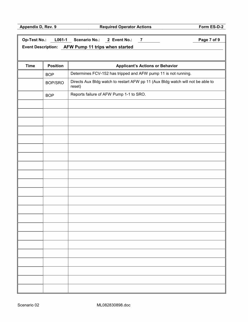
Op-Test No.: L061-1 Scenario No.: 2 Event No.: 7 Page 7 of 9
Event Description: AFW Pump 11 trips when started
Time Position Applicant’s Actions or Behavior
BOP Determines FCV-152 has tripped and AFW pump 11 is not running.
BOP/SRO Directs Aux Bldg watch to restart AFW pp 11 (Aux Bldg watch will not be able to reset)
BOP Reports failure of AFW Pump 1-1 to SRO.

Scenario 02 ML082830898.doc
Appendix D, Rev. 9 Required Operator Actions Form ES-D-2
Op-Test No.: L061-1 Scenario No.: 2 Event No.: 8 Page 8 of 9
Event Description: AFW Pump 13 discharge pressure transmitter failure
Time Position Applicant’s Actions or Behavior
BOP Determines AFW pp 13 is running but LCV-113 & 115 are closed.
BOP Places LCV-113 & 115 controllers in manual and increases demand to restore AFW flow to S/G’s 13 & 14. **
BOP Report failure of AFW Pump 1-3 to SRO.
** Critical Task

Scenario 02 ML082830898.doc
Appendix D, Rev. 9 Required Operator Actions Form ES-D-2
Op-Test No.: L061-1 Scenario No.: 2 Event No.: 9 Page 9 of 9
Event Description: AFW Pump 12 trips on overcurrent / Loss of Heat Sink
Time Position Applicant’s Actions or Behavior
SRO Transitions to FR-H.1, “Response to Loss of Secondary Heat Sink.”
• Verifies Secondary Heat Sink is Required.
• Verifies ECCS CCP Status
• Dispatches operators to investigate loss of pumps and to verify alignments.
• Direct RO to secure all RCPs.
• Direct BOP to control Steam Generator Pressure.
• Try to establish Main Feedwater Flow (Determines not available)
• Directs the establishment of Condensate Flow**
RO Stops all RCPs.
BOP Adjust 10% Steam Dump controllers to 1005 PSIG (8.38 turns)
BOP Depressurizes RCS using PORV – to less than 1915 psig.
RO Blocks PZR low pressure and low steam line pressure SI
BOP Resets FW Isolation
BOP Bypass Fdwtr Heaters and Cond Demins (FCV-55 & 230)
BOP Close ALL MSIVs and MSIV Bypass Vlvs.
BOP Depressurize 2 S/Gs to <490 psig using 10% Steam Dumps.
BOP Establishes feed flow from condensate system prior to Feed & Bleed criteria being met.**
BOP Stabilize Steam Generator pressures at 480 psig.
Terminate after condensate flow is established.
** Critical Task

Scenario 02 ML082830898.doc
MAJOR EVENT SUMMARY AND SCENARIO OBJECTIVES
L. Crew starts ramp to 100% power at 2-3 mw/min per OP L-4. Crew should perform a dilution for the power
ascension.
M. PORV PCV-474 opens to 25%. The operator should verify pressure less than 2335 psig, and try to close the
PORV. Since the PORV will not close, the block valve 8000A should then be closed. Follows up per PK 05-20.
N. S/G 11 10% steam dump.PCV-19 controller fails to 100% demand. Operator should verify pressure < 1020 psig
and try placing controller in Manual and decrease demand. This will not work, so operator should cut-in backup
air toggle switch and close 10% dump valve using backup air control switch.
O. Power range NI-43 fails high. Rods will drive in if in AUTO. Operator should diagnose NI problem and take rods
to Manual. SRO will refer to AP-5 for guidance. NI-43 will be defeated per AP-5 attachment to restore rod
control.
P. A condenser vacuum leak will cause entry into AP-7. This will require a Turbine trip, which should cause a
reactor trip above P-9. If below P-9, a load rejection will occur and rods will insert to match Tavg to no load Tref.
In this case, both MFW pumps will trip on low vacuum which will require a reactor trip. EOP E-0 will be entered.
Q. On the bus transfer from the Unit trip, 4KV bus H Startup feeder breaker will trip on overcurrent which will de-
energize the bus. This will cause a loss of power to AFW pp 12.
R. AFW pp 11 will trip on starting. Damage to its overspeed mechanism will render it inoperable.
S. AFW pp 13 discharge pressure transmitter will only go to 360 psig. This will cause LCV-113 & 115 to close to
prevent pump runout. The operator should see AFW pp 13 running, and place LCV-115 & 113 in manual to
restore AFW flow. Shortly after this is done, AFW pp 13 will trip on overcurrent. This will cause a loss of heat
sink and require transition to FR H-1 upon exiting E-0.
T. The scenario is terminated after flow is established from the condensate system per FR H-1.

Scenario 02 ML082830898.doc
ATTACHMENT 1 - SIMULATOR SET-UP
TIME LINE CONSOLE ENTRY SYMPTOMS/CUES/DESCRIPTION
Setup Simulator per Checklist
Init 512 50% power, MOL, CB = 937
• Integrators: BA - 0 and PW – 20 • Tags: CT – D/G 1-1 to manual & bkr
Setup Drill 81 Reset normal engineering values
Setup Drill 34 Clears D/G 11, place D/G in manual
Setup Drill 40 Clears TDAFW Pump
Swap to sequential valve.
CONTROL BOARD SETUP Copies of commonly used forms and procedures are available. Any tags are placed/removed as necessary. Primary integrator = 20 gal, Boron = 0 gal. Record PPC MAX (BOL = 99.8, MOL = 100.0, EOL = 100.2) on CC2 lamicoid The plant Abnormal Status Board is updated with last CCP CB near 937, stp I-1C every 8 hours. Circuit breaker flags are correct. Equipment status lamicoids are correct:
B.A. XFER PP SUPPLYING BLENDER - BA Pp 1-2
SUPPLYING IN-SERVICE SCW HX - CWP 1-1
AUTO RECLOSE FEATURE CUTIN ON THIS CWP - CWP 1-1
SELECTED TO BUS 2F - Cont. Rm. Vent Train 1 Bus F
SELECTED TO BUS 1H - Cont. Rm. Vent Train 1 Bus H
The proper Delta-I curve and Reactivity Handbook for the simulator INIT are in place The Rod Step Counters indicate correctly. PPC Setup:
o QP TAVG, ALM/MODE-1, QP CHARGING, BIG U1169 o RBU is updated. o PEN running. o R2B blowdown flows at 90 gpm.
o Reactor trip status correct 3(Pg 2 of Group display Mode-1). o Operational mode correct for current conditions.4
o Delta-I target slope matches Delta-I curve (DeltaI menu →Option 5, constants K0500-0503=100% power target DeltaI / 100)
SPDS (screens and time updating), A screen “RM”, B screen “SPDS”. The chart recorders are operating properly, and advanced. All typewriters are on, with adequate paper/ribbon/etc., and are in the “ON LINE” status. The Annunciator Horn is on (BELL ON). Sound Effects are on (SOUND ON). The video and audio systems are SECURED. Communications systems are turned on and functional
3 If not correct, place PPC display in ovrd mode, and press add/omit key. Type point Y0006D and select F2 to restore processing. This should update the trip breaker status. 4 Allow about ten minutes for the PPC to automatically update the plant mode. If still not correct, place PPC display in ovrd mode, and type APMC. Follow menu to manually override to correct mode.

Scenario 02 ML082830898.doc
TIMELINE AND INSTRUCTOR ACTIONS FOR SIMULATION X = manual entry required
X 0 min DRILL 6604 After SRO reports the crew has taken the watch, load session MALS, OVRs, etc. by DRILL FILE or MANUALLY (below)
0 min xmt afw3 5,375,0,0,d,0 AFW pp 13 discharge pressure limited to 360 psig, will close LCV-113 & 115 on pump start
5 min after ramp started
vlv pzr6 2,0.25,5,300,c,ggo PCV-474 opens to 25%
10 min after 8000A closed
cnh mss2 2,1,15,600, c,rrc8000a.lt.0.1
PCV-19 controller fails to 100%, must use b/u air to close
2 minutes after 10% steam dump is open
Report as Turbine Bldg watch noise from Pipe Rack area.
5 min after PCV-19 B/U air cut-in
mal nis6c act 200,5,600,c,xv3i345c NI-43 fails high
12 min after NI-43 comparator defeat
loa cnd1 act,0.2,60,720, c,xnii410d Condenser Vacuum leak
On AFW pp 11 start
mal afw1 act 0,0,0, c,ofpstdfp.gt.4100
FCV-152 trips when pump rpm > 4100
X When requested Report damage to overspeed trip mechanism, can’t reset
On tranfer to s/u bkr eps13 4,0,0,2,c,xv4o218r 52-hh-14 S/U fdr to bus H trips on overcurrent
After placing LCV-113 & 115 in manual
pmp afw2 6,5.06,1,30, c,xv3o151m.and.xv3o152m
AFW pp 13 trips on overcurrent
X ON Rx Trip Drill 32 NO Actions
X When requested Report pump motor hot to touch, overcurrent relay flags dropped at breaker
X When requested Dsc pzr1 act,0,0,0,d,0 Open Breaker for 8000A

Scenario 02 ML082830898.doc
DIABLO CANYON POWER PLANT
OPERATIONS SHIFT LOG UNIT 1
OPERATING MODE: 1 POWER LEVEL: 50 % GROSS GENERATION: 550 MWe NET GENERATION 515 MWe DAYS AT POWER: 120
Shift Manager Turnover
PRA RISK STATUS NEXT SHIFT: YELLOW - D/G 1-1 MOW
PROTECTED EQUIPMENT: Train B, Buses H & G, Prot. Sets II,III,IV
HOMELAND SECURITY THREAT LEVEL: YELLOW GRID STATUS NEXT SHIFT: Normal AVERAGE RCS CALCULATED LEAKRATE: 0.05 gpm
URGENT WORK:
* None
ACTIVE SHUTDOWN TECH SPECS / ECGS:
* D/G 1-1. Lube oil heater replacement. TS 3.8.1 Action B - 7 days. Declared inoperable 16 hours ago.
TURNOVER ITEMS:
*Repairs on D/G 1-1 are in process. Expected to be returned to service in 14 hours. STP I-1C was completed 1 hour ago. *Unit at 50% for last 3 days due to tunnel cleaning. This is complete with both CWP’s in service. Your crew is to ramp unit to 100% power. * OP L-4 step 6.2.3 is in progress, and complete up to sub-step d.2, all Prerequisites have been met.
OPERABILITY ITEMS:
* None
PRIORITY ITEMS FOR NEXT SHIFT:
*D/G 1-3 lube oil heater replacement
ANNUNCIATORS IN ALARM * PK 13-15, PK 14-16, PK 16-03, 04, 09, PK08-04, PK14-19, PK09-18

Scenario 02 ML082830898.doc
SHIFT FOREMAN TURNOVER
COMMENTS:
4. Reactivity management:
a. Time in core life: MOL
b. Power History: 50% for last 3 days.
c. Boron concentration is 937 ppm from a sample taken 4 hours ago.
d. Diluting 20 gallons every 2 – 3 hours.
e. The last dilution was completed 30 minutes ago.
f. ΔI is stable
5. No one is in Containment, no entries are expected
6. U-2 is operating at 100% power COMPENSATORY MEASURES:
None
CONTROL ROOM ABNORMAL STATUS
See Abnormal Status Board.
Ramp Plan for return to 100% Power
Perform one 200 gal dilution prior to ramp. Ramp Turbine at 3 MW/Min to 95% power. Leave Rod Control in Auto. Perform additional dilutions as needed to maintain Tavg and Tref matched.

Scenario 03 ML082830898.doc Rev.1
Appendix D, Rev. 9 Scenario Outline Form ES-D-1
Facility: Diablo Canyon Scenario No.: 3 Op-Test No.: L061-1
Examiners: Operators:
Initial Conditions: 25% BOL, 1182 ppm Turnover: PRA Status – Yellow. AFW pp 11 cleared for bearing replacement. CFCU 1-2 is cleared for motor replacement. High Swell Warning in effect. Reduce power to 20% on both units in the next 6 hours. Unit 2 power reduction to 20% was completed 10 minutes ago. Ramp to 20% power was delayed by problems with Main Feedwater Bypass valves. Issue has been resolved, continue ramp to 20% Per OP L-4.
Event No.
Malf. No. Event Type*
Event Description and Time Line
1 N Set 10% Steam Dumps for low power conditions.
2 R Ramp to 20% power due to high swell warning.
3 pmp ven8 C CFCU 14 over current trip 2 min after ramp started. (TS 3.6.6)
4 xmt pzr40 I Controlling Pressurizer level channel LT-459 fails low 7 min after CFCU 14 trip. (TS 3.3.1)
5 mal ccw2 C Letdown heat exchanger tube leak 4 min after letdown restored.
6 mal rcs4b M 600 gpm Steam Generator 12 tube rupture after FCV-361 is opened.
7 mal mss3b C Steam break outside containment on Steam Generator 12 on reactor trip.
*(N)ormal, (R)eactivity, (I)nstrument, (C)omponent, (M)ajor

Scenario 03 ML082830898.doc Rev.1
Appendix D, Rev. 9 Required Operator Actions Form ES-D-2
Op-Test No.: L061-1 Scenario No.: 3 Event No.: 1 Page 1 of 7
Event Description: Set 10% Steam Dumps for low power conditions
Time Position Applicant’s Actions or Behavior
SRO Reviews and briefs OP L-4 for setting 10% to 8.38 turns (1005 psig)
BOP Sets 10% steam dumps to 8.38 turns (1005 psig) for each dump valve (PCV 19,20,21,22)
• Places 10% dump controller Manual
• Sets controller to 8.38 turns
• Returns 10% controller to AUTO
Scenario 03 ML082830898.doc Rev.1
Appendix D, Rev. 9 Required Operator Actions Form ES-D-2
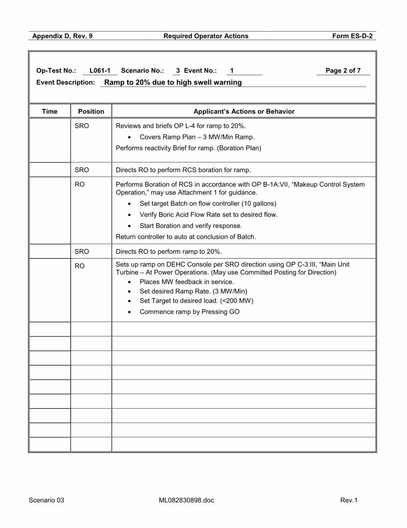
Op-Test No.: L061-1 Scenario No.: 3 Event No.: 1 Page 2 of 7
Event Description: Ramp to 20% due to high swell warning
Time Position Applicant’s Actions or Behavior
SRO Reviews and briefs OP L-4 for ramp to 20%.
• Covers Ramp Plan – 3 MW/Min Ramp.
Performs reactivity Brief for ramp. (Boration Plan)
SRO Directs RO to perform RCS boration for ramp.
RO Performs Boration of RCS in accordance with OP B-1A:VII, “Makeup Control System Operation,” may use Attachment 1 for guidance.
• Set target Batch on flow controller (10 gallons)
• Verify Boric Acid Flow Rate set to desired flow.
• Start Boration and verify response.
Return controller to auto at conclusion of Batch.
SRO Directs RO to perform ramp to 20%.
RO Sets up ramp on DEHC Console per SRO direction using OP C-3:III, “Main Unit Turbine – At Power Operations. (May use Committed Posting for Direction)
• Places MW feedback in service.
• Set desired Ramp Rate. (3 MW/Min)
• Set Target to desired load. (<200 MW)
• Commence ramp by Pressing GO
Scenario 03 ML082830898.doc Rev.1
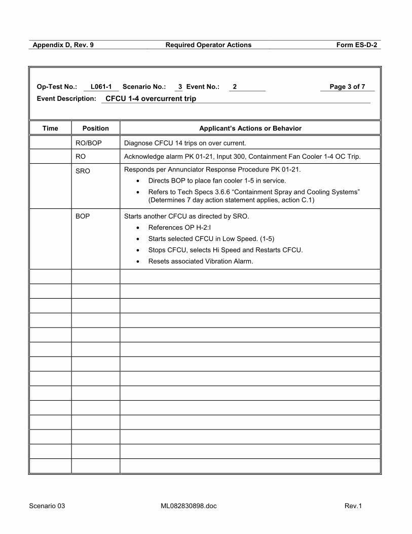
Appendix D, Rev. 9 Required Operator Actions Form ES-D-2
Op-Test No.: L061-1 Scenario No.: 3 Event No.: 2 Page 3 of 7
Event Description: CFCU 1-4 overcurrent trip
Time Position Applicant’s Actions or Behavior
RO/BOP Diagnose CFCU 14 trips on over current.
RO Acknowledge alarm PK 01-21, Input 300, Containment Fan Cooler 1-4 OC Trip.
SRO Responds per Annunciator Response Procedure PK 01-21.
• Directs BOP to place fan cooler 1-5 in service.
• Refers to Tech Specs 3.6.6 “Containment Spray and Cooling Systems” (Determines 7 day action statement applies, action C.1)
BOP Starts another CFCU as directed by SRO.
• References OP H-2:I
• Starts selected CFCU in Low Speed. (1-5)
• Stops CFCU, selects Hi Speed and Restarts CFCU.
• Resets associated Vibration Alarm.

Scenario 03 ML082830898.doc Rev.1
Appendix D, Rev. 9 Required Operator Actions Form ES-D-2
Op-Test No.: L061-1 Scenario No.: 3 Event No.: 3 Page 4 of 7
Event Description: Pzr level channel LT-459 fails low
Time Position Applicant’s Actions or Behavior
BOP/RO Diagnose Pressurizer Level Channel LT-459 Failing Low.
SRO Direct RO to place charging control in MANUAL and reduces to seals only.
RO Places Charging Control in Manual and controls flow to maintain Pressurizer Level.
RO Acknowledge alarm PK 05-21, input 314, Pressurizer Level Low
SRO Determines AP-5, “Malfunction of Eagle 21 Protection or Control Channel” is appropriate procedure to address this event.
BOP Diagnose Letdown Isolation and report to SRO
RO Diagnose Loss of Pressurizer Heaters, Low Level cutout, report to SRO.
SRO Enters AP-5, “Malfunction of Eagle 21 Protection or Control Channel.”
• Verifies Primary and Secondary Control Systems are controlling properly in AUTO (Step to place charging in manual will be completed prior to this step)
• Determines failure not to be related to Eagle 21.
• Determines alternate channel is available for selection. (Directs RO to select alternate Pressurizer Level Control Channel)
• Determines redundant recorder is available. (Directs RO to select matching level recorder)
• Determines LTB and Steam Dumps are not actuated.
• Notifies Maintenance to investigate
• Uses attachment 4.1 determine affected control systems.
• Directs BOP to restore letdown.
• Directs RO to return Pressurizer Heaters to auto.
• Refers to Tech Spec 3.3.1.M (Place channel in tripped position within 72 hours or be in MODE 3 in 78 hours.)
RO Selects alternate channel for Pressurizer level control and recorder input.
BOP/RO Re-establishes letdown per OP B-1A:XII, CVCS – Letdown System, Establish Normal Letdown following Letdown Isolation.
• Places PCV-135 in manual and opens to 60%
• Places TCV-130 in manual and opens to 50%
• Increase charging flow to ~87 gpm and adjust seal injection flow.
• Open Letdown Orifice valve 8149C
• Adjust PCV-135 and TCV-130 and return to AUTO
• Control Charging Flow as necessary to return PZR level to Reference.
RO Places Pressurizer Heaters in Auto.

Scenario 03 ML082830898.doc Rev.1
Appendix D, Rev. 9 Required Operator Actions Form ES-D-2
Op-Test No.: L061-1 Scenario No.: 3 Event No.: 4 Page 5 of 7
Event Description: Letdown Heat Exchanger tube leak
Time Position Applicant’s Actions or Behavior
RO/BOP Diagnose unexpected change in VCT level and letdown flow.
RO Acknowledge alarm PK 11-21, input 1066, Process Monitor Hi Rad
SRO Responds per Annunciator Response Procedure PK 11-21.
• Directs BOP to check process radiation monitors.
• Verifies automatic actions have occurred (CCW Head tank RCV-16 Closed)
• Transitions to AP-11, Malfunction of CCW System, section B.
BOP Check radiation monitors, can use PPC RAD MAP – Reports RE-17A and B in alarm.
BOP/RO Verifies RCV-16, CCW Head Tank Vent is closed.
SRO Enters AP-11 ‘Malfunction of CCW System” Section B: CCW System Inleakage.
• Verifies CCW Head tank isolation. (RCV-16 Closed)
• Verifies RCP Operability.
• Verifies CCW Surge Tank Makeup, not source of inleakage, requests sample.
• Determines Leak Location - Letdown Heat Exchanger
• Refers to OP AP-18 “Letdown Line Failure” (as time permits)
• Directs Isolation of Letdown Heat Exchanger
• Directs placement of Excess Letdown in service.
BOP Isolates normal letdown, closes 8149C and LCV’s 459 & 460.**
RO Reduces charging flow to seals only.
BOP Isolates Normal Charging – Closes 8146.
BOP Places Excess Letdown in service per OP B-1A:IV
• Opens CCW supply to Excess Letdown HX – FCV-361.
** Critical Task

Scenario 03 ML082830898.doc Rev.1
Appendix D, Rev. 9 Required Operator Actions Form ES-D-2
Op-Test No.: L061-1 Scenario No.: 3 Event No.: 5 Page 6 of 7
Event Description: S/G 12 tube rupture
Time Position Applicant’s Actions or Behavior
RO Acknowledge alarm PK 11-06, Input 423, SJAE HI Radiation
RO Acknowledge alarm, PK 11-18, Input 471, Main Steam Line Hi Rad.
BOP Checks for increasing Radiation Monitor trends, reports RE-15 and 72 counts increasing.
BOP Checks for decreasing RCS pressure and Pressurizer Level, Reports rapid drop in both indications.
SRO Responds per Annunciator Response Procedure PK 11-18.
• Diagnoses a Steam Generator Tube Failure and Transitions to AP-3, Steam Generator Tube Failure
• Directs BOP to isolate Letdown and start additional Charging Pumps (if time permits)
• Directs Manual Safety Injection
BOP Starts additional charging pump and isolates letdown as directed.
RO Performs a Manual Safety Injection
RO/BOP Perform immediate actions:
• Verify Reactor Tripped.
• Verify Turbine Tripped.
• Verify Vital 4 KV Buses Energized.
• Check SI Actuated.
SRO Enter E-0, “Reactor Trip or Safety Injection”
• Verify completion of Immediate Actions.
• Recognizes RCP trip criteria met, directs RCPs to be tripped. **
• Direct implementation of Appendix E.
• Checks status of AFW flows, direct throttling to minimum required flow.
• Determines SG 1-2 is Faulted recognizes procedure transition criteria met for EOP E-2, “Faulted Steam Generator Isolation”.
• Implements F-0, monitors CSFSTs – No Challenges
• Determines that SG 1-2 is faulted and transitions to E-2, “Faulted Steam Generation Isolation.”
RO Implements Appendix E
• Performs verification steps in Appendix E
• Reports status to SRO at step 9 and 18
BOP Throttles AFW flow as directed by SRO.
• Closes TD AFW pump LCVs.
• Throttles MD AFW LCVs.
RO/BOP Trips Reactor Coolant pumps**

Scenario 03 ML082830898.doc Rev.1
** Critical Task
Appendix D, Rev. 9 Required Operator Actions Form ES-D-2

Scenario 03 ML082830898.doc Rev.1
Op-Test No.: L061-1 Scenario No.: 3 Event No.: 6 Page 7 of 7
Event Description: Main Steam Line break on S/G 12
Time Position Applicant’s Actions or Behavior
SRO Conducts Procedure Transition Brief for E-2, “Faulted Steam Generation Isolation”.
• Plant Status
• Major Actions
• Questions
SRO Enter E-2, “Faulted Steam Generation Isolation”.
• Directs Isolation of Steam Generator 1-2 (Early Isolation may have been performed as part of E-0)
• Transitions to E-3 at Step 7 of E-2, valid alarms on SG Rad Monitors.
BOP Performs Isolation Steps for Steam Generator 1-2 **
• Verifies All MSIVs and Bypass Valves Closed
• Checks for any Intact SG
• Identifies Faulted SGs as only 1-2.
• Isolates Faulted SG 1-2 o Verifies Feedwater Isolation Valve Closed – FCV-439 o Verifies Blowdown Isolation Valves are Closed o Verifies 10% Dump Valve is closed o Verifies AFW flow is isolated** o Verifies Steam Supply to TDAFW Pump is closed, FCV-37
• Removes Subcooled Margin Monitor Input on PAM 4.
SRO Conducts Procedure Transition Brief for E-3, “Steam Generator Tube Rupture”.
• Plant Status
• Major Actions
• Foldout Page Assignments
• Questions SRO Enters E-3, “Steam Generator Tube Rupture”
• Directs isolation of Steam Generator 1-2 (Early Isolation may have been performed as part of E-0)
• Determines Feedwater flow should remain isolated to SG 1-2.**
• Determines Ruptured SG pressure is less than 225 psig.**
• Determines transition to ECA-3.1” SGTR with Loss of Reactor Coolant – Subcooled Recovery Desired.”
RO/BOP Verify Isolation Steps are completed as directed by SRO.
Terminate scenario after transition to ECA 3.1
** Critical Task
Scenario 03 ML082830898.doc Rev.1
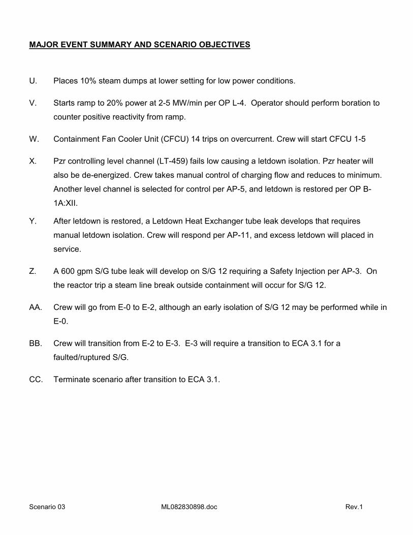
MAJOR EVENT SUMMARY AND SCENARIO OBJECTIVES
U. Places 10% steam dumps at lower setting for low power conditions.
V. Starts ramp to 20% power at 2-5 MW/min per OP L-4. Operator should perform boration to
counter positive reactivity from ramp.
W. Containment Fan Cooler Unit (CFCU) 14 trips on overcurrent. Crew will start CFCU 1-5
X. Pzr controlling level channel (LT-459) fails low causing a letdown isolation. Pzr heater will
also be de-energized. Crew takes manual control of charging flow and reduces to minimum.
Another level channel is selected for control per AP-5, and letdown is restored per OP B-
1A:XII.
Y. After letdown is restored, a Letdown Heat Exchanger tube leak develops that requires
manual letdown isolation. Crew will respond per AP-11, and excess letdown will placed in
service.
Z. A 600 gpm S/G tube leak will develop on S/G 12 requiring a Safety Injection per AP-3. On
the reactor trip a steam line break outside containment will occur for S/G 12.
AA. Crew will go from E-0 to E-2, although an early isolation of S/G 12 may be performed while in
E-0.
BB. Crew will transition from E-2 to E-3. E-3 will require a transition to ECA 3.1 for a
faulted/ruptured S/G.
CC. Terminate scenario after transition to ECA 3.1.

Scenario 03 ML082830898.doc Rev.1
ATTACHMENT 1 - SIMULATOR SET-UP
TIME LINE CONSOLE ENTRY SYMPTOMS/CUES/DESCRIPTION
Setup Simulator per Checklist
Init NRC03 25% power, BOL, CB = 1182
• Integrators: BA - 4 and PW – 0 • Tags: FCV-95, FCV-37 & 38 , CFCU 1-2
Setup Drill 81 Reset normal engineering values
Setup dsc vent1 act,0,0,0,d,0 (Open Bkr) Clears CFCU 1-2 – Hang tag
Setup Drill 40
Turn on Pzr backup heaters
1 PPC SDS with SCREENS display
Clears TDAFWP
Per ramp plan
CONTROL BOARD SETUP Copies of commonly used forms and procedures are available. Any tags are placed/removed as necessary – close FCV-37 & 38, then place tags. CFCU 1-2 Primary integrator = 0 gal, Boron = 4 gal. Record PPC MAX (BOL = 99.8, MOL = 100.0, EOL = 100.2) on CC2 lamicoid The plant Abnormal Status Board is updated with last CCP CB near 1182 and current date, XLD boron conc at 2200
ppm. Circuit breaker flags are correct. Equipment status lamicoids are correct:
B.A. XFER PP SUPPLYING BLENDER - BA Pp 1-2
SUPPLYING IN-SERVICE SCW HX - CWP 1-1
AUTO RECLOSE FEATURE CUTIN ON THIS CWP - CWP 1-1
SELECTED TO BUS 2F - Cont. Rm. Vent Train 1 Bus F
SELECTED TO BUS 1H - Cont. Rm. Vent Train 1 Bus H
The proper Delta-I curve and Reactivity Handbook for the simulator INIT are in place The Rod Step Counters indicate correctly. PPC Setup:
o QP TAVG, ALM/MODE-1, QP CHARGING, BIG U1169 o RBU is updated. o PEN running. o R2B blowdown flows at 90 gpm.
o Reactor trip status correct 5(Pg 2 of Group display Mode-1). o Operational mode correct for current conditions.6
o Delta-I target slope matches Delta-I curve (DeltaI menu →Option 5, constants K0500-0503=100% power target DeltaI / 100)
SPDS (screens and time updating), A screen “RM”, B screen “SPDS”. The chart recorders are operating properly, and advanced. All typewriters are on, with adequate paper/ribbon/etc., and are in the “ON LINE” status. The Annunciator Horn is on (BELL ON). Sound Effects are on (SOUND ON). The video and audio systems are SECURED. Communications systems are turned on and functional.
5 If not correct, place PPC display in ovrd mode, and press add/omit key. Type point Y0006D and select F2 to restore processing. This should update the trip breaker status. 6 Allow about ten minutes for the PPC to automatically update the plant mode. If still not correct, place PPC display in ovrd mode, and type APMC. Follow menu to manually override to correct mode.
Scenario 03 ML082830898.doc Rev.1
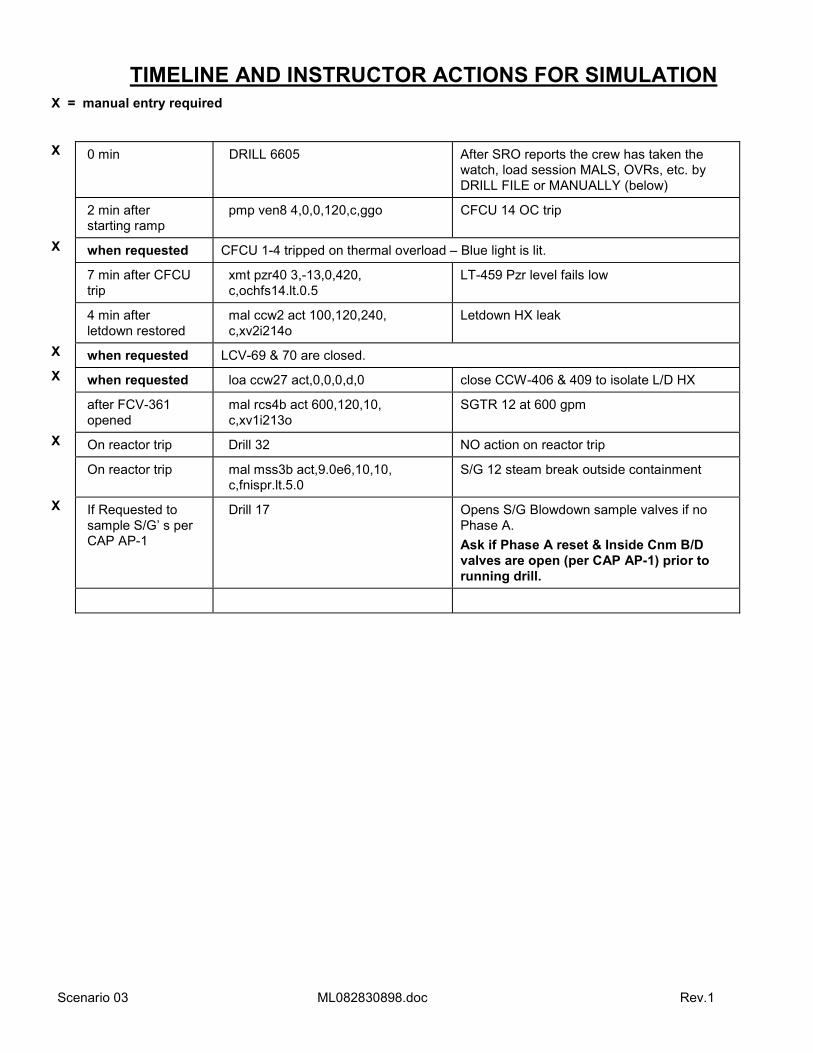
TIMELINE AND INSTRUCTOR ACTIONS FOR SIMULATION X = manual entry required
X 0 min DRILL 6605 After SRO reports the crew has taken the watch, load session MALS, OVRs, etc. by DRILL FILE or MANUALLY (below)
2 min after starting ramp
pmp ven8 4,0,0,120,c,ggo CFCU 14 OC trip
X when requested CFCU 1-4 tripped on thermal overload – Blue light is lit.
7 min after CFCU trip
xmt pzr40 3,-13,0,420, c,ochfs14.lt.0.5
LT-459 Pzr level fails low
4 min after letdown restored
mal ccw2 act 100,120,240, c,xv2i214o
Letdown HX leak
X when requested LCV-69 & 70 are closed.
X when requested loa ccw27 act,0,0,0,d,0 close CCW-406 & 409 to isolate L/D HX
after FCV-361 opened
mal rcs4b act 600,120,10, c,xv1i213o
SGTR 12 at 600 gpm
X On reactor trip Drill 32 NO action on reactor trip
On reactor trip mal mss3b act,9.0e6,10,10, c,fnispr.lt.5.0
S/G 12 steam break outside containment
X If Requested to sample S/G’ s per CAP AP-1
Drill 17 Opens S/G Blowdown sample valves if no Phase A.
Ask if Phase A reset & Inside Cnm B/D valves are open (per CAP AP-1) prior to running drill.

Scenario 03 ML082830898.doc Rev.1
DIABLO CANYON POWER PLANT
OPERATIONS SHIFT LOG UNIT 1
OPERATING MODE: 1 POWER LEVEL: 25 % GROSS GENERATION: 1198 MWe NET GENERATION 1155 MWe DAYS AT POWER: 15
Shift Manager Turnover
PRA RISK STATUS NEXT SHIFT: YELLOW - TDAFP 1-1 MOW
PROTECTED EQUIPMENT: Train A & B, Buses F, G & H, Prot Sets I,II,III & IV
HOMELAND SECURITY THREAT LEVEL: YELLOW GRID STATUS NEXT SHIFT: Normal AVERAGE RCS CALCULATED LEAKRATE: 0.05 gpm
URGENT WORK:
* None
ACTIVE SHUTDOWN TECH SPECS / ECGS:
* TDAFP 1-1 - TS 3.7.5 Action B - 72 hours, due in 70 hours. .
TURNOVER ITEMS: * A bearing is being replaced on TDAFP 1-1. It was removed from service 2 hours ago. Work is expected to be completed in approximately 12 more hours. * High Swell Warning in effect. Reduce power to 20% on both units in the next 6 hours. Unit 2 power reduction to 20% was completed 10 minutes ago. * Ramp to 20% power was delayed by problems with Main Feedwater Bypass valves. Issue has been resolved, continue ramp to 20% Per OP L-4 step 6.4.3.t. * OP O-28 “Intake Management” actions have been implemented. * Camera at Intake is OOS for maintenance, do back in 6 hours. * CFCU 1-2 is cleared for motor replacement.
OPERABILITY ITEMS:
* None
PRIORITY ITEMS FOR NEXT SHIFT:
* Reduce power to 20% per OP L-4. * OP L-4 step 6.4.3 is in progress, and complete up to sub-step 6.4.3t, all Prerequisites have been met.
ANNUNCIATORS IN ALARM * PK 09-18

Scenario 03 ML082830898.doc Rev.1
SHIFT FOREMAN TURNOVER
COMMENTS:
7. Reactivity management:
a. Time in core life: BOL
b. Power History: 100%
c. Boron concentration is 1182 ppm from a sample taken 4 hours ago.
d. Borate 30 gallon batches every 20 minutes for first 2 hours of ramp per Reactor Engineering.
e. Ramp at 3 MW/min to 220 MW.
f. Use rods as needed to maintain ΔI with in +/- 2% of target.
8. No one is in Containment, no entries are expected
9. U-2 is ramping to 20% power. COMPENSATORY MEASURES:
None
CONTROL ROOM ABNORMAL STATUS
See Abnormal Status Board.
Ramp Plan for reduction to 20% Power
Borate 10 gallon per Reactor Engineering.
Ramp down to 200 MW, at 3 MW/min.
Leave Rod Control in Auto, Use rods in manual as needed to maintain ΔI with in +/- 2% of target.
Scenario 04 ML082830898.doc
Appendix D, Rev. 9 Scenario Outline Form ES-D-1
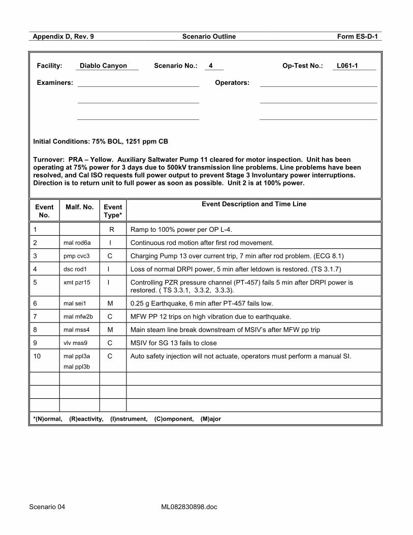
Facility: Diablo Canyon Scenario No.: 4 Op-Test No.: L061-1
Examiners: Operators:
Initial Conditions: 75% BOL, 1251 ppm CB Turnover: PRA – Yellow. Auxiliary Saltwater Pump 11 cleared for motor inspection. Unit has been operating at 75% power for 3 days due to 500kV transmission line problems. Line problems have been resolved, and Cal ISO requests full power output to prevent Stage 3 Involuntary power interruptions. Direction is to return unit to full power as soon as possible. Unit 2 is at 100% power.
Event No.
Malf. No. Event Type*
Event Description and Time Line
1 R Ramp to 100% power per OP L-4.
2 mal rod6a I Continuous rod motion after first rod movement.
3 pmp cvc3 C Charging Pump 13 over current trip, 7 min after rod problem. (ECG 8.1)
4 dsc rod1 I Loss of normal DRPI power, 5 min after letdown is restored. (TS 3.1.7)
5 xmt pzr15 I Controlling PZR pressure channel (PT-457) fails 5 min after DRPI power is restored. ( TS 3.3.1, 3.3.2, 3.3.3).
6 mal sei1 M 0.25 g Earthquake, 6 min after PT-457 fails low.
7 mal mfw2b C MFW PP 12 trips on high vibration due to earthquake.
8 mal mss4 M Main steam line break downstream of MSIV’s after MFW pp trip
9 vlv mss9 C MSIV for SG 13 fails to close
10 mal ppl3a
mal ppl3b
C Auto safety injection will not actuate, operators must perform a manual SI.
*(N)ormal, (R)eactivity, (I)nstrument, (C)omponent, (M)ajor

Scenario 04 ML082830898.doc
Appendix D, Rev. 9 Required Operator Actions Form ES-D-2
Op-Test No.: L061-1 Scenario No.: 4 Event No.: 1 Page 1 of 9
Event Description: Ramp to 100% power
Time Position Applicant’s Actions or Behavior
SRO Reviews and briefs OP L-4 for ramp to 100%.
• Covers Ramp Plan – 5 MW/Min Ramp.
• Performs reactivity Brief for ramp. (Dilution Plan)
SRO Directs RO to perform RCS dilution for ramp.
RO Performs Dilution of RCS in accordance with OP B-1A:VII, “Makeup Control System Operation,” may use Attachment 1 for guidance.
• Set target Batch on flow controller (100 gallons)
• Verify Primary Water Flow Rate set to desired flow.
• Start Dilution and verify response.
• Return controller to auto at conclusion of Batch.
SRO Directs RO to perform ramp to 100%.
RO Sets up ramp on DEHC Console per SRO direction using OP C-3:III, “Main Unit Turbine – At Power Operations. (May use Committed Posting for Direction)
• Raise Valve Position Limit.
• Places MW feedback in service.
• Set desired Ramp Rate. (3 MW/Min)
• Set Target to desired load. (>1100 MW)
• Commence ramp by Pressing GO

Scenario 04 ML082830898.doc
Appendix D, Rev. 9 Required Operator Actions Form ES-D-2
Op-Test No.: L061-1 Scenario No.: 4 Event No.: 2 Page 2 of 9
Event Description: Uncontrolled outward rod motion
Time Position Applicant’s Actions or Behavior
RO Diagnoses unexpected control rod motion.
SRO Directs RO to place Rods in Manual
RO Places Rod Control in Manual and verifies rod motion has stopped.**
SRO Enters AP-12A, “Continuous Withdrawal or Insertion of a Control Rod Bank.”
• Verifies Rod Control is in Manual
• Verifies Rod Motion has stopped.
• Directs RO to match Tavg and Tref using turbine as needed.
• Contacts Maintenance Services.
RO/BOP May place ramp on hold to maintain temperature.
BOP Restart Ramp as needed for temperature control.
** Critical Task

Scenario 04 ML082830898.doc
Appendix D, Rev. 9 Required Operator Actions Form ES-D-2
Op-Test No.: L061-1 Scenario No.: 4 Event No.: 3 Page 3 of 9
Event Description: Charging pump 13 overcurrent trip
Time Position Applicant’s Actions or Behavior
RO/BOP Diagnose trip of CCP 1-3
RO Acknowledge alarm PK 04-16, input 217, Charging Pump 1-3 OC Trip.
SRO Responds per Annunciator Response Procedure PK 04-16.
• Checks indications to confirm alarm – Blue light on pump
• Determines AP-17 “Loss of Charging” is appropriate procedure to address this event.
BOP Diagnose Letdown Isolation and report to SRO.
SRO Enters AP-17, “Loss of Charging.” Section A.
• Directs BOP to verify a suction flowpath.
• Directs BOP to Verify charging pump recirc valves are open.
• Directs RO to Close FCV-128
• Directs BOP to Start ECCS Charging pump (either one)
• Directs RO to establish minimum charging flow to RCP seals only.
• Directs BOP and RO to reestablish Letdown flow.
• Refers to ECG 8.1(Charging Pump No. 3 shall be operable – 7 day action)
BOP Performs actions as directed by SRO
• Verifies suction path from VCT to charging pump suction is aligned.
• Verifies CCP recirc valves are open (8105 and 8106).
• Starts ECCS charging Pump (either one), verifies steady amps.
RO Performs actions as directed by SRO.
• Closes FCV-128
• Establishes minimum flow (9 gpm) to RCP seals only.
BOP/RO Re-establishes letdown per OP B-1A:XII, CVCS – Letdown System, Establish Normal Letdown following Letdown Isolation.
• Places PCV-135 in manual and opens to 60%
• Places TCV-130 in manual and opens to 50%
• Increase charging flow to ~87 gpm and adjust seal injection flow.
• Open Letdown Orifice valve 8149C
• Adjust PCV-135 and TCV-130 and return to AUTO
• Control Charging Flow as necessary to return PZR level to Reference.
RO Returns Pzr level control to Auto (as time permits)

Scenario 04 ML082830898.doc
Appendix D, Rev. 9 Required Operator Actions Form ES-D-2
Op-Test No.: L061-1 Scenario No.: 4 Event No.: 4 Page 4 of 9
Event Description: Loss of DRPI power
Time Position Applicant’s Actions or Behavior
RO/BOP Diagnose Loss of DRPI indication.
SRO Direct RO to verify Rod Control is in Manual.
RO Verify Rod Control is in Manual.
RO Acknowledge alarm PK 03-21, input 553, Rod Position Indication Urgent.
SRO Responds per Annunciator Response Procedure PK 03-21.
• Verify Rod Control is in Manual
• Verify Ramp is placed on HOLD
• Refer to Tech Spec 3.1.7, DRPI System (Determines Action B applies – rods to manual, monitor temperature and restore in 24 hours.)
• Direct Nuclear Operator to place DRPI on backup power supply.
• Once power is restored direct RO to maintain Control Rods in Manual.

Scenario 04 ML082830898.doc

Scenario 04 ML082830898.doc
Appendix D, Rev. 9 Required Operator Actions Form ES-D-2
Op-Test No.: L061-1 Scenario No.: 4 Event No.: 5 Page 5 of 9
Event Description: Pzr Pressure Channel PT-457 fails low.
Time Position Applicant’s Actions or Behavior
BOP/RO Diagnose Pressurizer Pressure Channel PT-457 Failing Low.
SRO Direct RO to place pressure control in MANUAL and control pressure.
RO Places Pressure Control in Manual and controls to maintain Pressurizer Pressure.
RO Acknowledge alarm PK 05-17, input 535, Pressurizer Pressure Low channel 457.
SRO Responds per Annunciator Response Procedure PK 05-17.
• Directs BOP to channel check all PZR Pressure Channels.
• Determines AP-5, “Malfunction of Eagle 21 Protection or Control Channel” is appropriate procedure to address this event.
BOP Report failure of PT-457 and other channels are SAT.
SRO Enters AP-5, “Malfunction of Eagle 21 Protection or Control Channel.”
• Verifies Primary and Secondary Control Systems are controlling properly in AUTO (Step to place pressure control in manual will be completed prior to this step)
• Determines failure not to be related to Eagle 21.
• Determines alternate channel is available for selection. (Directs RO to select alternate Pressurizer Pressure Control Channel)
• Determines redundant recorder is available. (Directs RO to select matching Pressurizer pressure recorder)
• Determines LTB and Steam Dumps are not actuated.
• Notifies Maintenance to investigate
• Uses attachment 4.1 determine affected control systems.
• Directs RO to restore Pressurizer Heaters
• Refers to Tech Spec o 3.3.1.M (Place channel in tripped position within 72 hours or be in
MODE 3 in 78 hours.) o 3.3.2.D (Place channel in tripped position within 72 hours or be in
MODE 3 in 78 hours.)
RO Selects alternate channel (455/456) for Pressurizer Pressure Control and Recorder Input.
RO Returns Pressurizer Pressure Control to Auto (if time permits), including Heaters.

Scenario 04 ML082830898.doc
Appendix D, Rev. 9 Required Operator Actions Form ES-D-2
Op-Test No.: L061-1 Scenario No.: 4 Event No.: 6 & 7 Page 6 of 9
Event Description: 0.25g Earthquake/Main Feedwater Pump 1-2 Trip
Time Position Applicant’s Actions or Behavior
RO/BOP/
SRO
Diagnose seismic event, based on ground motion and seismic alarms.
RO/BOP Diagnose Main Feedwater Pump 1-2 High Vibrations
RO Acknowledge multiple alarms (high priority is PK 09-12, input 588, FWP 1-2 Turbine Trip) RED Window.
SRO Responds per Annunciator Response Procedure PK 09-12 ‘Main Feedwater Pump Trip”
• May Enter AP-15 “Loss of Feedwater Flow”

Scenario 04 ML082830898.doc
Appendix D, Rev. 9 Required Operator Actions Form ES-D-2
Op-Test No.: L061-1 Scenario No.: 4 Event No.: 8 Page 7 of 9
Event Description: Main steam line break downstream of MSIV’s
Time Position Applicant’s Actions or Behavior
BOP/RO Diagnoses Steam line break
SRO Directs Manual Reactor Trip and Safety Injection
RO Performs Manual Reactor Trip and Safety Injection (Auto will not work)**
RO/BOP Perform immediate actions:
• Verify Reactor Tripped.
• Verify Turbine Tripped.
• Verify Vital 4 KV Buses Energized.
• Check SI Actuated.
SRO Enter E-0, “Reactor Trip or Safety Injection”
• Verify completion of Immediate Actions.
• Direct implementation of Appendix E.
• Checks status of AFW flows, direct throttling to minimum required flow.
• Determines RCS is not intact and recognizes procedure transition criteria met for EOP E-2, “Faulted Steam Generator Isolation”.
• Implements F-0, monitors CSFSTs – No Challenges
• Transitions to E-2, “Faulted Steam Generator Isolation”.
RO Implements Appendix E
• Performs verification steps in Appendix E
• Reports status to SRO at step 9 and 18
BOP Throttles AFW flow as directed by SRO.
• Closes TD AFW pump LCVs.
• Throttles MD AFW LCVs. (May Isolate flow to SG 1-3)
** Critical Task

Scenario 04 ML082830898.doc
Appendix D, Rev. 9 Required Operator Actions Form ES-D-2
Op-Test No.: L061-1 Scenario No.: 4 Event No.: 9 Page 8 of 9
Event Description: MSIV for S/G 13 fails open
Time Position Applicant’s Actions or Behavior
SRO Conducts Procedure Transition Brief for E-2, “Faulted Steam Generation Isolation”.
• Plant Status
• Major Actions
• Foldout Page Assignments
• Questions
SRO Enter E-2, “Faulted Steam Generation Isolation”.
• Directs Isolation of Steam Generator 1-3 (Early Isolation may have been performed as part of E-0)
• Determines ECCS Flow should be reduced.
• Transitions to E-1.1 ”SI Termination” at Step 8 of E-2.
BOP Performs Isolation Steps for Steam Generator 1-3
• Verifies All MSIVs and Bypass Valves Closed o Determines MSIV 43 (Steam Lead 3) will not close. o Dispatches Nuclear Operator to implement Appendix L
• Checks for any Intact SG
• Identifies Faulted SGs as only 1-3.
• Isolates Faulted SG 1-3 o Verifies Feedwater Isolation Valve Closed – FCV-440 o Verifies Blowdown Isolation Valves are Closed o Verifies 10% Dump Valve is closed o Verifies AFW flow is isolated ** o Verifies Steam Supply to TDAFW Pump is closed, FCV-38
• Removes Subcooled Margin Monitor Input on PAM 4.
BOP Reports MSIV 43 will not close to SRO.
** Critical Task

Scenario 04 ML082830898.doc
Appendix D, Rev. 9 Required Operator Actions Form ES-D-2
Op-Test No.: L061-1 Scenario No.: 4 Event No.: 10 Page 9 of 9
Event Description: Auto Safety Injection will not actuate/ SI Termination
Time Position Applicant’s Actions or Behavior
See event 8 for actions for auto SI malfunction.
SRO Conducts Procedure Transition Brief for E-1.1, “SI Termination”.
• Plant Status
• Major Actions
• Foldout Page Assignments
• Questions
Enters E-1.1, “SI Termination”
• Directs RO to Reset SI
• Directs RO/BOP to align Charging.
• Verifies Pressure is stable or increasing.
• Directs RO to isolate Charging Injection.
• Directs RO to secure both SI Pumps.
• Directs RO to secure both RHR Pumps.
RO Resets both trains of Safety Injection.
BOP Resets Auto Transfer Relays (3) – Blue lights out.
RO Secures 1 ECCS Charging Pump.
RO Closes 8803 A/B and 8801 A/B to isolate charging injection
RO/BOP Establish normal charging flow and seal injection
Terminate scenario after Normal Charging is established
Scenario 04 ML082830898.doc
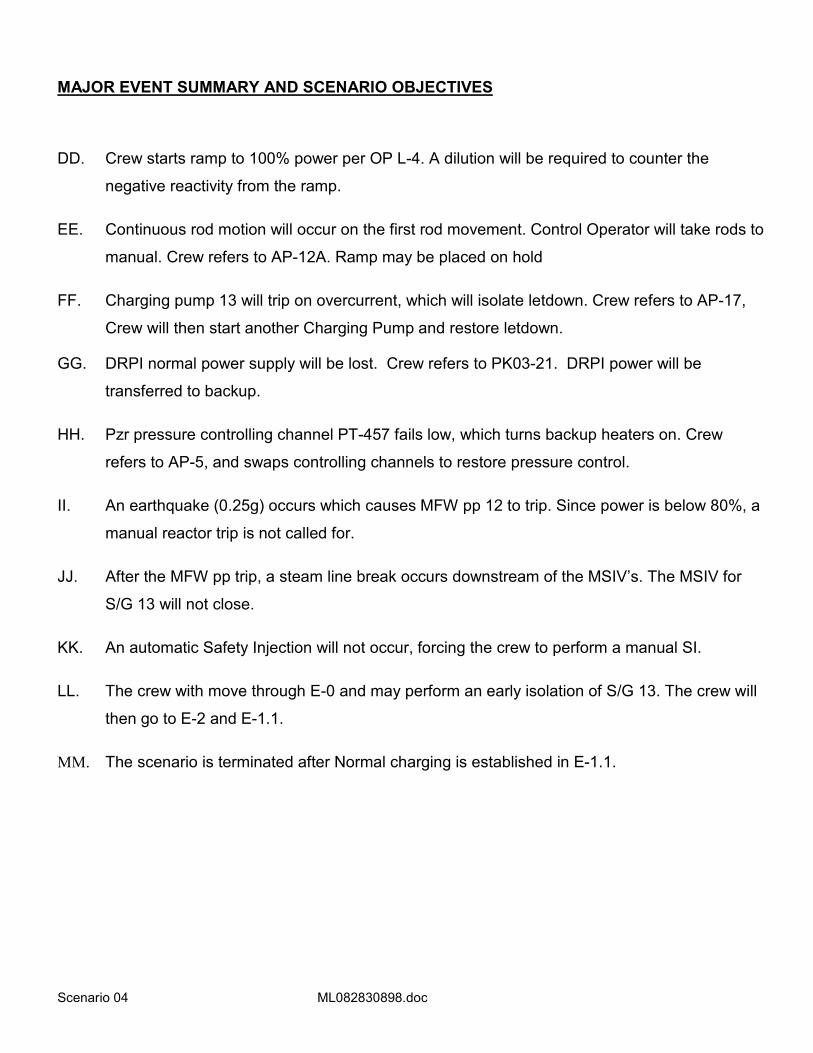
MAJOR EVENT SUMMARY AND SCENARIO OBJECTIVES
DD. Crew starts ramp to 100% power per OP L-4. A dilution will be required to counter the
negative reactivity from the ramp.
EE. Continuous rod motion will occur on the first rod movement. Control Operator will take rods to
manual. Crew refers to AP-12A. Ramp may be placed on hold
FF. Charging pump 13 will trip on overcurrent, which will isolate letdown. Crew refers to AP-17,
Crew will then start another Charging Pump and restore letdown.
GG. DRPI normal power supply will be lost. Crew refers to PK03-21. DRPI power will be
transferred to backup.
HH. Pzr pressure controlling channel PT-457 fails low, which turns backup heaters on. Crew
refers to AP-5, and swaps controlling channels to restore pressure control.
II. An earthquake (0.25g) occurs which causes MFW pp 12 to trip. Since power is below 80%, a
manual reactor trip is not called for.
JJ. After the MFW pp trip, a steam line break occurs downstream of the MSIV’s. The MSIV for
S/G 13 will not close.
KK. An automatic Safety Injection will not occur, forcing the crew to perform a manual SI.
LL. The crew with move through E-0 and may perform an early isolation of S/G 13. The crew will
then go to E-2 and E-1.1.
MM. The scenario is terminated after Normal charging is established in E-1.1.

Scenario 04 ML082830898.doc
ATTACHMENT 1 - SIMULATOR SET-UP
TIME LINE CONSOLE ENTRY SYMPTOMS/CUES/DESCRIPTION
Setup Simulator per Checklist
Init NRC04 75% power, BOL, CB = 1251
• Integrators: BA - 4 and PW – 0 • Tags: ASW pp 11 C/S
Setup Drill 81 Reset normal engineering values
Setup Transfer turbine to sequential valve and remove feebacks.
Prepares Turbine for ramp up.
Setup Start ASW pp 12 & align ASW and CCW thru CCW HX 12. Shutdown ASW pp 11. Then manually enter: • loa asw6 act,0,0,0,d,0
• ser 0146 act,0,0,0,d,0
Swaps to ASW pp 12 going thru CCW HX 12.
Secures ASW pp 11 and opens DC knife switch and turns off UV alarm to simulate racking out the pump breaker.
Swap CL and Radwaste tags to CCW HX 1-2
CONTROL BOARD SETUP Copies of commonly used forms and procedures are available. Any tags are placed/removed as necessary. Primary integrator = 0 gal, Boron = 4 gal. Record PPC MAX (BOL = 99.8, MOL = 100.0, EOL = 100.2) on CC2 lamicoid The plant Abnormal Status Board is updated with last CCP CB near 1251 and current date. Circuit breaker flags are correct. Equipment status lamicoids are correct:
B.A. XFER PP SUPPLYING BLENDER - BA Pp 1-2
SUPPLYING IN-SERVICE SCW HX - CWP 1-1
AUTO RECLOSE FEATURE CUTIN ON THIS CWP - CWP 1-1
SELECTED TO BUS 2F - Cont. Rm. Vent Train 1 Bus F
SELECTED TO BUS 1H - Cont. Rm. Vent Train 1 Bus H
The proper Delta-I curve and Reactivity Handbook for the simulator INIT are in place The Rod Step Counters indicate correctly. PPC Setup:
o QP TAVG, ALM/MODE-1, QP CHARGING, BIG U1169 o RBU is updated. o PEN running. o R2B blowdown flows at 90 gpm.
o Reactor trip status correct 7(Pg 2 of Group display Mode-1). o Operational mode correct for current conditions.8
o Delta-I target slope matches Delta-I curve (DeltaI menu →Option 5, constants K0500-0503=100% power target DeltaI / 100)
SPDS (screens and time updating), A screen “RM”, B screen “SPDS”. The chart recorders are operating properly, and advanced. All typewriters are on, with adequate paper/ribbon/etc., and are in the “ON LINE” status. The Annunciator Horn is on (BELL ON). Sound Effects are on (SOUND ON). The video and audio systems are SECURED.
7 If not correct, place PPC display in ovrd mode, and press add/omit key. Type point Y0006D and select F2 to restore processing. This should update the trip breaker status. 8 Allow about ten minutes for the PPC to automatically update the plant mode. If still not correct, place PPC display in ovrd mode, and type APMC. Follow menu to manually override to correct mode.

Scenario 04 ML082830898.doc
Communications systems are turned on and functional.

Scenario 04 ML082830898.doc
TIMELINE AND INSTRUCTOR ACTIONS FOR SIMULATION X = manual entry required
X 0 min DRILL 6606 After SRO reports the crew has taken the watch, load session MALS, OVRs, etc. by DRILL FILE or MANUALLY (below)
0 min mal rod6a act 8,0,0,c,xc1o026l Continuous rod motion on first outward rod movement. ***
0 min mal ppl3a act 1,0,0,d,0
mal ppl3b act 1,0,0,d,0
Auto SI is prevented from being actuated.
0 min vlv mss9 1,0,0,0,d,0 FCV-43 S/G 13 MSIV fails open
7 min after rod problem
pmp cvc3 6,7.02,5,420,c,jmlrod6(1) CCP 13 overcurrent trip.
when requested Report that CCP 13 motor hot to touch, C phase over current flag at 52-HG-11.
5 min after letdown restored
dsc rod1 act,0,0,300,c,xv2i214o Loss of DRPI normal power supply.
X when requested Report that the normal supply breaker (52-1F-45) has tripped open and will not reset. Circuit downstream of the breaker checks out SAT. (Time Compression)
X when requested loa eps1 act,1,0,0,d,0 DRPI on backup power
5 min after DRPI restored
xmt pzr21 2,0,0,300,c,iepsdrpi PT-457 fails low
6 min after PT-457 failure
mal sei1 act 0.25,10,360, c,pxmtpzr(3).lt.1300
0.25g earthquake
On Seismic mal mfw2b act 24,20,10,c,jmlsei1 MFW pp 12 hi vibration trip
On MFW pp trip mal mss4 act 1e+07,120,30, c,jmlmfw2(2)
Main steam line break downstream of MSIV’s
On reactor trip Drill 32 NO actions on a reactor trip
when requested Report that Appendix L has been performed and FCV-43 will not close.
*** if required to cause outward rod motion in a reasonable time period, increase RCS boron concentration in 1 ppm segments using a 60 sec ramp in mal rcs5 to get Tavg < Tref.

Scenario 04 ML082830898.doc
DIABLO CANYON POWER PLANT
OPERATIONS SHIFT LOG UNIT 1
OPERATING MODE: 1 POWER LEVEL: 75 % GROSS GENERATION: 901 MWe NET GENERATION 865 MWe DAYS AT POWER: 21
Shift Manager Turnover
PRA RISK STATUS NEXT SHIFT: YELLOW – ASW PP 1-1 MOW
PROTECTED EQUIPMENT: Train B, Buses H & G, Prot. Sets II,III,IV
HOMELAND SECURITY THREAT LEVEL: YELLOW GRID STATUS NEXT SHIFT: CAL ISO has declared a Stage 2 Emergency, Stage 3
Emergency is imminent unless more generation comes on line.
AVERAGE RCS CALCULATED LEAKRATE: 0.05 gpm
URGENT WORK:
* None
ACTIVE SHUTDOWN TECH SPECS / ECGS:
* ASW PP 1-1 – motor inspection. T.S 3.7.4.A - 72 hours. Due in 62 hours. .
TURNOVER ITEMS:
* ASW PP 1-1 was cleared 10 hours ago to perform a motor inspection. It is expected to be returned to service in 8 hours. * Unit has been operating at 75% power for 3 days due to 500kV transmission line problems. Line problems have been resolved, and Cal ISO requests full power output to prevent Stage 3 Involuntary power interruptions. * Direction is to return unit to full power as soon as possible per OP L-4. * OP L-4 step 6.2.3 is in progress, and complete up to sub-step d.2, all Prerequisites have been met.
OPERABILITY ITEMS:
* None
PRIORITY ITEMS FOR NEXT SHIFT:
* Return unit to full power as soon as possible.
ANNUNCIATORS IN ALARM * None

Scenario 04 ML082830898.doc
SHIFT FOREMAN TURNOVER
COMMENTS:
10. Reactivity management:
a. Time in core life: BOL
b. Power History: 75% for last 3 days.
c. Boron concentration is 1251 ppm from a sample taken 4 hours ago.
d. Commence 100 gallon dilutions every 15 minutes for first hour per Reactor Engineering.
e. Commence ramp to 1160 MW at 5 MW/min. Lower ramp rate as needed to keep ΔI in target band and Tavg +/- 3 F of Tref.
f. Leave rods in Auto, unless needed to maintain ΔI in target band.
11. No one is in Containment, no entries are expected
12. U-2 is operating at 100% power COMPENSATORY MEASURES:
None
CONTROL ROOM ABNORMAL STATUS
See Abnormal Status Board.
Ramp Plan for return to 100% Power
Perform one 300 gal dilution prior to ramp. Ramp Turbine at 5 MW/Min to 95% power. Leave Rod Control in Auto. Perform additional dilutions as needed to maintain Tavg and Tref matched.
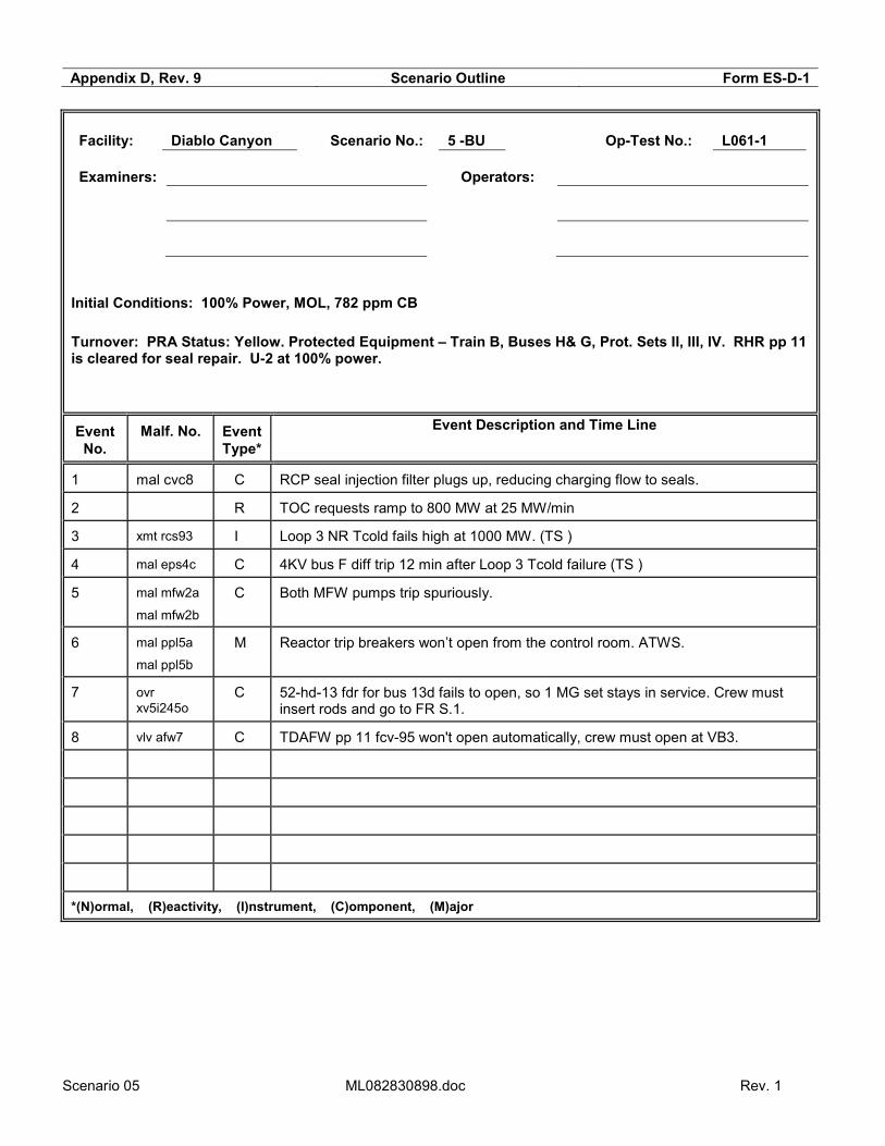
Scenario 05 ML082830898.doc Rev. 1
Appendix D, Rev. 9 Scenario Outline Form ES-D-1
Facility: Diablo Canyon Scenario No.: 5 -BU Op-Test No.: L061-1
Examiners: Operators:
Initial Conditions: 100% Power, MOL, 782 ppm CB Turnover: PRA Status: Yellow. Protected Equipment – Train B, Buses H& G, Prot. Sets II, III, IV. RHR pp 11 is cleared for seal repair. U-2 at 100% power.
Event No.
Malf. No. Event Type*
Event Description and Time Line
1 mal cvc8 C RCP seal injection filter plugs up, reducing charging flow to seals.
2 R TOC requests ramp to 800 MW at 25 MW/min
3 xmt rcs93 I Loop 3 NR Tcold fails high at 1000 MW. (TS )
4 mal eps4c C 4KV bus F diff trip 12 min after Loop 3 Tcold failure (TS )
5 mal mfw2a
mal mfw2b
C Both MFW pumps trip spuriously.
6 mal ppl5a
mal ppl5b
M Reactor trip breakers won’t open from the control room. ATWS.
7 ovr xv5i245o
C 52-hd-13 fdr for bus 13d fails to open, so 1 MG set stays in service. Crew must insert rods and go to FR S.1.
8 vlv afw7 C TDAFW pp 11 fcv-95 won't open automatically, crew must open at VB3.
*(N)ormal, (R)eactivity, (I)nstrument, (C)omponent, (M)ajor

Scenario 05 ML082830898.doc Rev. 1
Appendix D, Rev. 9 Required Operator Actions Form ES-D-2
Op-Test No.: L061-1 Scenario No.: 5 Event No.: 1 Page 1 of 6
Event Description: RCP seal injection filter plugs.
Time Position Applicant’s Actions or Behavior
RO Diagnose RCP seal injection filter plugging.
RO Acknowledge alarm PK 04-22, input 498, RCP Seal Injection Filter 1 Delta P Hi
SRO Responds per Annunciator Response Procedure PK 04-22.
• Direct RO to throttle HCV-142 as needed to control flow.
• Monitor RCP operation – PPC Display – RCP
• Direct Nuclear Operator to swap seal injection filters.
• Direct RO to reestablish RCP seal flow, when filter is swapped.
• Contacts Maintenance to replace seal injection filter.
RO Reestablish seal injection flow of >8 gpm using HCV-142.
BOP Monitor RCP parameters as directed by SRO.

Scenario 05 ML082830898.doc Rev. 1
Appendix D, Rev. 9 Required Operator Actions Form ES-D-2
Op-Test No.: L061-1 Scenario No.: 5 Event No.: 2 Page 2 of 6
Event Description: Ramp to 800 MW at 25 MW/min
Time Position Applicant’s Actions or Behavior
SRO Receives call from TOC – Ramp to 800 MW at 25 MW/MIN.
SRO Enters AP-25 “Rapid Load Reduction or Shutdown.
• Directs RO to Reduce Turbine Load – 800 MW target @ 25 MW/MIN.
• Verifies Control Rods inserting in Auto.
• Verifies Pressurizer backup heaters – ON.
• Verifies Charging system operation is adequate.
• Verifies Digital Feedwater Controls controlling SG Levels in Auto.
• Determine Requirements and Direct Boration of RCS. (Based on Reactivity Handbook Guidance – 167 gallons BA with in 2 hours)
BOP/RO Sets up ramp on DEHC Console per SRO direction using OP C-3:III, “Main Unit Turbine – At Power Operations. (May use Committed Posting for Direction)
• Places MW feedback in service.
• Set desired Ram Rate. (25MW/Min)
• Set Target to desired load. (800 MW)
• Commence ramp by Pressing GO
RO Verify Control Rods inserting in Auto in response to Ramp.
RO Verifies Backup Pressurizer Heater groups are ON.
BOP/RO Verify Charging System operation is adequate.
• Verifies at Least One Charging Pump is in service.
• Controls charging in Manual as needed to prevent Letdown system flashing.
RO Performs Boration of RCS using Boration Checklist and Makeup controller.
• Set Target Batch on flow controller (as determined by SRO)
• Verify Boric Acid Flow rate set to desired flow.
• Start Boration and verify response.

Scenario 05 ML082830898.doc Rev. 1
Appendix D, Rev. 9 Required Operator Actions Form ES-D-2
Op-Test No.: L061-1 Scenario No.: 5 Event No.: 3 Page 3 of 6
Event Description: Loop 3 NR Tcold fails high at 1000 MW.
Time Position Applicant’s Actions or Behavior
RO Diagnose inward rod motion as unwarranted.
BOP Diagnose Loop 3 Tavg Failure.
SRO Direct RO to Place Rods in Manual and Ramp on HOLD.
RO Select Manual on Rod Control and place Ramp on HOLD.
RO Acknowledge Alarm PK 04-02, Input 388, Tavg deviation LP3.
SRO Responds per Annunciator Response Procedure PK 06-03.
• Directs BOP to channel check all Temperature Channels.
• Determines AP-5, “Malfunction of Eagle 21 Protection or Control Channel” is appropriate procedure to address this event.
BOP Report failure of Loop 3 Temperature channels and all others are SAT.
SRO Enters AP-5, “Malfunction of Eagle 21 Protection or Control Channel.”
• Verifies Primary and Secondary Control Systems are controlling properly in AUTO (Step to place rod control in manual will be completed prior to this step)
• Determines failure is related to Eagle 21.
• Dispatches operator to Eagle 21 Protection Set 3 racks 11 & 13.
• Determines alternate channel is available for selection. (Directs RO to Loopout Loop 3 ΔT & Tavg) and return rods to auto.
• Determines LTB and Steam Dumps are not actuated.
• Notifies Maintenance to investigate
• Uses attachment 4.1 determine affected control systems.
• Refers to Tech Spec o 3.3.1.E (Place channel in tripped position within 72 hours or be in
MODE 3 in 78 hours.) o 3.3.2.M (Place channel in tripped position within 72 hours or be in
MODE 3 in 78 hours.)
RO Defeats Loop 3 inputs to rod control, Loop 3 ΔT & Tavg.
RO Returns Rod control to Automatic when Tavg/Tref is within 1˚F.
RO/BOP Resumes ramp (as time permits)

Scenario 05 ML082830898.doc Rev. 1
Appendix D, Rev. 9 Required Operator Actions Form ES-D-2
Op-Test No.: L061-1 Scenario No.: 5 Event No.: 4 Page 4 of 6
Event Description: 4KV bus F diff trip 12 min after Loop 3 Tcold failure
Time Position Applicant’s Actions or Behavior
BOP Diagnoses failure of 4kV Bus “F”
RO Recognizes loss of DRPI, places rods in manual
RO Acknowledges multiple alarms – Determines PK 18-17, input 141 is highest priority, 4 kV bus F UV.
SRO Responds per Annunciator response Procedure PK18-17 (PK18-16 and 18-22)
• Determines AP-27, “Loss of Vital 4 kV and/or 480V Bus” is appropriate procedure to address event.
SRO Enters AP-27, “Loss of Vital 4 kV and/or 480V Bus.”
• Determines DRPI is de-energized – directs RO to Place Rods in Manual and place Ramp on HOLD.
• Directs Nuclear Operator to place DRPI on Backup.
• Contacts Maintenance to investigate failure.
• Directs RO/BOP to verify Pumps are running (Starts CCW pump 1-3)
• Implements attachment 4.1 for loss of 480V Bus F.
• Directs BOP to place PORV PCV-474 in closed position.
• Direct BOP to place CFCU 1-5 in service.
• Direct BOP to secure Diesel Generator 1-3
• Direct Nuclear Operators to place Battery Charger 1-1 on Charger 121
• Refers to Tech Specs : o 3.8.1, AC Sources Operating, Action B. o 3.8.9, Distribution Systems Operating, Action A o 3.4.11, PORVs, Action B – most limiting – 1 hour.
BOP Manually starts alternate equipment as required:
• CFCU 15
• CCW pp13
BOP Positions PCV-474 to close
BOP Shuts down D/G 1-3
RO Returns Control Rods to Auto when DRPI is restored.

Scenario 05 ML082830898.doc Rev. 1
Appendix D, Rev. 9 Required Operator Actions Form ES-D-2
Op-Test No.: L061-1 Scenario No.: 5 Event No.: 5, 7, 8, 9 Page 5 of 6
Event Description: Feed Pumps trip / ATWS
Time Position Applicant’s Actions or Behavior
RO/BOP/
SRO
Diagnose both Main Feedwater Pumps have tripped, manually trips the reactor.
RO/BOP
SRO
Recognizes Reactor Trip Initiate without Actuation.
SRO Directs RO and BOP to Perform Immediate Actions
RO Attempts a manual Reactor Trip – Reports Reactor did not trip
BOP Attempts to open 13D/13E breakers – Reports 13D will not open.
SRO Diagnose an ATWS
RO Manually inserts control rods **
BOP Trips main turbine **
SRO Enters E-0, “Reactor Trip or Safety Injection”
• Determines Reactor will not trip.
• Determines Transition to FR-S.1”Response to Nuclear Power Generation ATWS” is required.
SRO Enters FR-S.1, Response to Nuclear Power Generation ATWS”
• Verifies Control Rods are be inserted
• Dispatch personnel to open Reactor Trip Breakers Locally.
• Verify turbine is tripped.
• Verify status of AFW – Direct BOP to start TDAFW Pump
• Directs RO to Start Emergency Boration
• Verifies Reactor is sub-critical & adequate SDM
• Determines Reactor is tripped and recognizes a procedure transition criterion is met for EOP E-0 “Reactor Trip or Safety Injection.”
BOP Diagnoses that AFW Pump 1-1 has failed to start.
• Starts TDAFW pump **
RO Reports to SRO when Reactor Trip Breakers are opened.
RO Initiates emergency boration
Terminate scenario after transition to E-0.1

Scenario 05 ML082830898.doc Rev. 1
Appendix D, Rev. 9 Required Operator Actions Form ES-D-2
Op-Test No.: L061-1 Scenario No.: 5 Event No.: 6 Page 6 of 6
Event Description: Both Main Feedwater pumps trip
Time Position Applicant’s Actions or Behavior
BOP Reports to SRO both MFW pumps are tripped, no main Feedwater flow is available.
SRO Acknowledge report of No Main Feedwater Available.

Scenario 05 ML082830898.doc Rev. 1
MAJOR EVENT SUMMARY AND SCENARIO OBJECTIVES
NN. RCP seal injection filter plugs up, reducing charging flow to seals. Crew refers to PK 04-22
and swaps to other filter.
OO. TOC requests ramp down to 800 MW at 25 MW/min.
PP. At 1000 MW, a Loop 3 Tcold RTD fails high, which causes rods to drive in. Rod control is
taken to manual and crew refers to AP-5 for actions.
QQ. 4KV Bus F de-energizes due to a differential trip. Crew refers to AP-27 for actions.
RR. Both MFW pumps trip spuriously. Crew should try to manually trip the reactor. Crew goes
from E-0 to FR S.1 since 52-HD-13 breaker will not open from the control room.
SS. Turbine driven AFW pp 11 must be manually started from VB3.
TT. Crew transitions back to E-0 from FR S.1 and then to E-0.1 for Reactor trip recovery.
UU. Terminate scenario after transition to E-0.1.

Scenario 05 ML082830898.doc Rev. 1
ATTACHMENT 1 - SIMULATOR SET-UP
TIME LINE CONSOLE ENTRY SYMPTOMS/CUES/DESCRIPTION
Setup Simulator per Checklist
Init 510 100% power, MOL, CB = 782
• Integrators: BA - 0 and PW – 40 • Tags: CT – RHR pp 11
Setup Drill 81 Reset normal engineering values
Setup • loa rhr9 act,0,0,0,d,0
• ser 0219 act,0,0,0,d,0
Clears RHR pp 1-1, overides DC undervoltage alarm off to simulate Breaker racked out
CONTROL BOARD SETUP Copies of commonly used forms and procedures are available. Any tags are placed/removed as necessary. Primary integrator = 40 gal, Boron = 0 gal. Record PPC MAX (BOL = 99.8, MOL = 100.0, EOL = 100.2) on CC2 lamicoid The plant Abnormal Status Board is updated with last CCP CB near 40 and current date. Circuit breaker flags are correct. Equipment status lamicoids are correct:
B.A. XFER PP SUPPLYING BLENDER - BA Pp 1-2
SUPPLYING IN-SERVICE SCW HX - CWP 1-1
AUTO RECLOSE FEATURE CUTIN ON THIS CWP - CWP 1-1
SELECTED TO BUS 2F - Cont. Rm. Vent Train 1 Bus F
SELECTED TO BUS 1H - Cont. Rm. Vent Train 1 Bus H
The proper Delta-I curve and Reactivity Handbook for the simulator INIT are in place The Rod Step Counters indicate correctly. PPC Setup:
o QP TAVG, ALM/MODE-1, QP CHARGING, BIG U1169 o RBU is updated. o PEN running. o R2B blowdown flows at 90 gpm.
o Reactor trip status correct 9(Pg 2 of Group display Mode-1). o Operational mode correct for current conditions.10
o Delta-I target slope matches Delta-I curve (DeltaI menu →Option 5, constants K0500-0503=100% power target DeltaI / 100)
SPDS (screens and time updating), A screen “RM”, B screen “SPDS”. The chart recorders are operating properly, and advanced. All typewriters are on, with adequate paper/ribbon/etc., and are in the “ON LINE” status. The Annunciator Horn is on (BELL ON). Sound Effects are on (SOUND ON). The video and audio systems are SECURED. Communications systems are turned on and functional.
9 If not correct, place PPC display in ovrd mode, and press add/omit key. Type point Y0006D and select F2 to restore processing. This should update the trip breaker status. 10 Allow about ten minutes for the PPC to automatically update the plant mode. If still not correct, place PPC display in ovrd mode, and type APMC. Follow menu to manually override to correct mode.

Scenario 05 ML082830898.doc Rev. 1
TIMELINE AND INSTRUCTOR ACTIONS FOR SIMULATION X = manual entry required
X 0 min DRILL 6607 After SRO reports the crew has taken the watch, load session MALS, OVRs, etc. by DRILL FILE or MANUALLY (below)
0 min mal pp15a act,3,0,0,d,0
mal pp15b act,3,0,0,d,0
ATWS (13D & E Available)
0 min ovr xv5i245o act,0,0,0,d,0 52-hd-13 fdr for bus 13d fails to open
0 min vlv afw7 1,0,0,0,d,xv3i219 tdafwp fcv-95 won't open automatically, clears when c/s taken to open
3 min mal cvc8 act 100,120,180,d,0 SEAL INJECTION FILTER 11 PLUGGED
X When requested Report Seal Injection Filter 11 dP is pegged high.
X Aux Bldg watch loa cvc3 act,1,30,0,d,0 valve in seal injection filter 12
X Aux Bldg watch loa cvc2 act,0,30,0,d,0 valve out seal injection filter 11
X When desired CALL AS TOC Require Ramp to 800 Mw Net. Start ramp within 5 minutes, request 25 MW/min ramp rate.
At 1000 MW xmt rcs93 3,679,30,0,c,smss.lt.1000 Loop 3 NR Tcold fails high
X When requested Report Rack 13 has trouble LED.
12 min after Tcold failure
mal eps4c act 2,0,720, c,txmt410b(3).gt.675
4KV bus F diff trip
X When requested Report burnt insulation smell from 4KV bus F room.
X When reqested loa eps1 act,1,0,0,d,0 transfers DRPI to backup
X When requested Drill 46 swap batt 11 -> chrg 121
10 min after bus differential
mal mfw2a act 25,5,10,
mal mfw2b act 25,5,10,
both MFW pp's trip
X When requested mal pp15a clr
mal pp15b clr
Locally opens Train A & B RTBs

Scenario 05 ML082830898.doc Rev. 1
DIABLO CANYON POWER PLANT
OPERATIONS SHIFT LOG UNIT 1
OPERATING MODE: 1 POWER LEVEL: 100 % GROSS GENERATION: 1198 MWe NET GENERATION 1155 MWe DAYS AT POWER: 120
Shift Manager Turnover
PRA RISK STATUS NEXT SHIFT: YELLOW – RHR PP 1-1 MOW
PROTECTED EQUIPMENT: Train B, Buses H & G, Prot. Sets II,III,IV
HOMELAND SECURITY THREAT LEVEL: YELLOW GRID STATUS NEXT SHIFT: Midway #3 line cleared AVERAGE RCS CALCULATED LEAKRATE: 0.05 gpm
URGENT WORK:
* None
ACTIVE SHUTDOWN TECH SPECS / ECGS:
* RHR PP 1-1 -pump seal repair. T.S 3.5.2.A - 72 hours. Due in 62 hours. .
TURNOVER ITEMS:
* RHR PP 1-1 was cleared 10 hours ago to repair a pump seal. It is expected to be returned to service in 8 hours.
OPERABILITY ITEMS:
* None
PRIORITY ITEMS FOR NEXT SHIFT:
* RHR PP 1-1 pump seal repairs.
ANNUNCIATORS IN ALARM * None
Scenario 05 ML082830898.doc Rev. 1
SHIFT FOREMAN TURNOVER
COMMENTS:
13. Reactivity management:
a. Time in core life: MOL
b. Power History: 100%
c. Boron concentration is 782 ppm from a sample taken 4 hours ago.
d. Diluting 40 gallons every 2 hours
e. Last dilution was 30 minutes ago
f. ΔI is stable
14. No one is in Containment, no entries are expected
15. U-2 is operating at 100% power COMPENSATORY MEASURES:
None
CONTROL ROOM ABNORMAL STATUS
See Abnormal Status Board.