Embed Size (px)
Citation preview

Instructions for Continued Appendix D
Airworthiness, Issue 3 Replacement Interval Summary
November 27, 2012 Page D 1
APPENDIX D
REPLACEMENT INTERVAL SUMMARY
COMPONENT LIMIT ACTION Envelope: Rip Panel Velcro 100 hrs of Operation Replace
Tempilabels 100 hrs or Annually Add 2 new ones Basket: none Burner: MK III & MK IV Standard REGO #7553 Blast Valve Blast Valve O-ring part number F128R 100 hrs or Annually Replace MKIII & MK IV Standard REGO #7553 Blast Valve Blast Valve Teflon back-up ring part number F128T 100 hrs or Annually Replace MK IV Standard REGO #7901 Blast Valve Blast Valve O-ring part number F901O 100 hrs or Annually Replace All Burners 10 Years in Service Replace Liquid Fuel Hoses Vapor Fuel Hoses
Fuel System: Manifold Fuel Hoses 10 Years in Service Replace Fuel Tank: Pressure Relief Valve 10 Years in Service Replace
Instruments: Batteries 100 hrs or Annually Replace

Instructions for Continued Appendix D
Airworthiness, Issue 3 Replacement Interval Summary
November 27, 2012 Page D 2
THIS PAGE INTENTIONALLY BLANK
Instructions for Continued Appendix E
Airworthiness, Issue 3 Basket Material Specifications
November 01, 2012 Page E 1
APPENDIX E
BASKET MATERIAL SPECIFICATIONS
Material: Specification: Rattan Kooboo, sizes 4-6 mm natural 7-9 mm natural
5.5 mm milled 7.5 mm milled
8-10 mm natural 12-14 mm natural Tohiti 18-20 mm natural Tohiti 22-25 mm natural
Solid Floor 1/2" (12mm) Marine Grade Plywood 3/4" (18mm) Marine Grade Plywood
Skids Oak, Maple, Ash or Other Hardwood
Skid overlay nylon or UHMW
Suspension cable 6mm diameter, 6 x 19, Stainless Steel Handle Rope 3/4” diameter soft Polypropylene 5/16” diameter soft Polypropylene 1/4” diameter soft Polypropylene Scuff leather 9 - 11 oz. Latigo
Scuff Rawhide Water Buffalo Limed Hide Bolster Suede 4 - 4 1/2 oz. Bolster Leather 4 - 5 oz. cowhide 6 – 8 oz. bullhide Bolster Cordura 11 oz.
Bolster & Horizontal Scuff Lacing 1/8” polyester braided
Scuff Rawhide Vertical Lacing Water Buffalo Limed Hide 1/8” Thongs Flexi-Rigid Poles 1 1/4” O.D. nylon 101 annealed
Rope Handle Reinforcement 3/8” O.D. nylon 101

Instructions for Continued Appendix E
Airworthiness, Issue 3 Basket Material Specifications
November 01, 2012 Page E 2
THIS PAGE INTENTIONALLY BLANK
Instructions for Continued Appendix F
Airworthiness, Issue 3 Worcester Liquid Withdrawal Valve
November 01, 1999 Page F 1
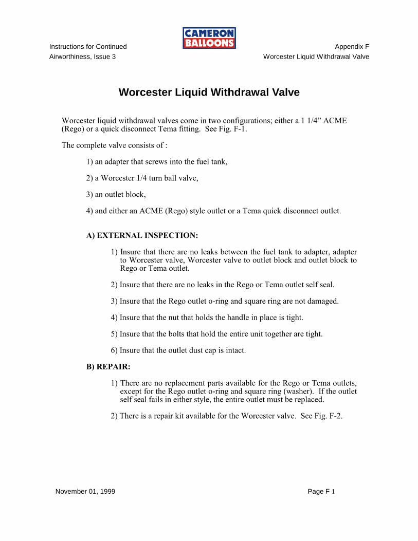
Worcester Liquid Withdrawal Valve
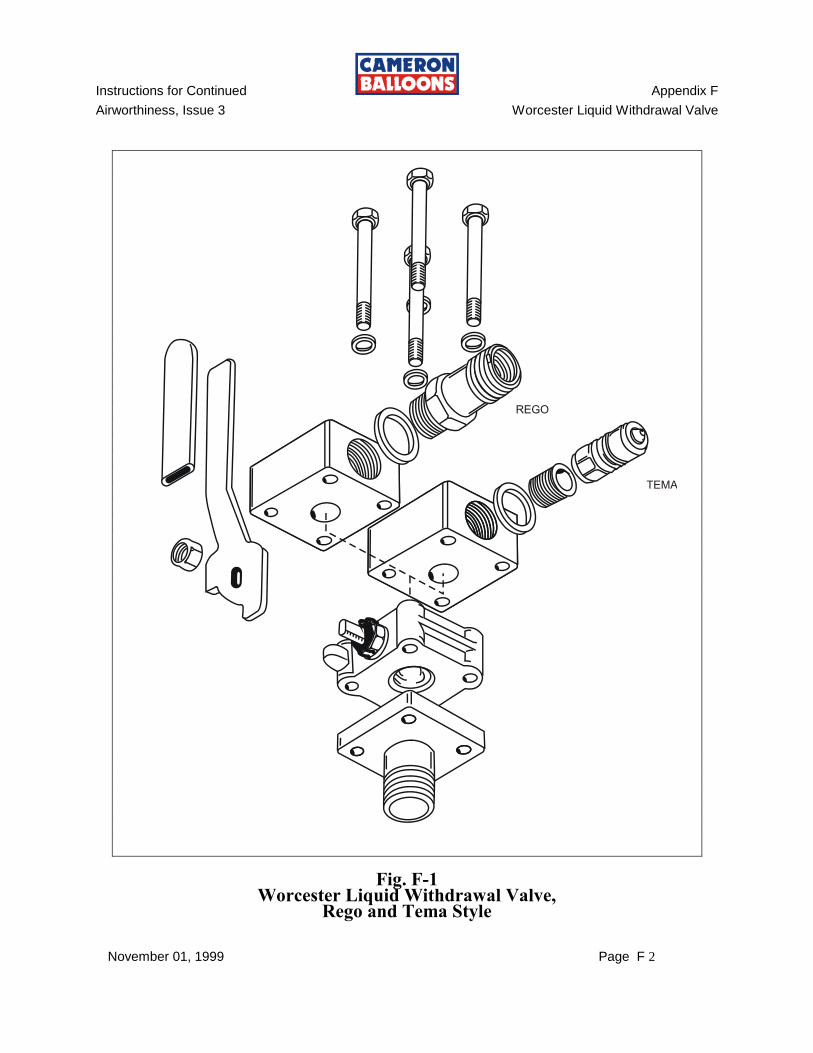
Worcester liquid withdrawal valves come in two configurations; either a 1 1/4” ACME (Rego) or a quick disconnect Tema fitting. See Fig. F-1. The complete valve consists of : 1) an adapter that screws into the fuel tank, 2) a Worcester 1/4 turn ball valve, 3) an outlet block, 4) and either an ACME (Rego) style outlet or a Tema quick disconnect outlet.
A) EXTERNAL INSPECTION: 1) Insure that there are no leaks between the fuel tank to adapter, adapter
to Worcester valve, Worcester valve to outlet block and outlet block to Rego or Tema outlet.
2) Insure that there are no leaks in the Rego or Tema outlet self seal. 3) Insure that the Rego outlet o-ring and square ring are not damaged. 4) Insure that the nut that holds the handle in place is tight. 5) Insure that the bolts that hold the entire unit together are tight. 6) Insure that the outlet dust cap is intact. B) REPAIR: 1) There are no replacement parts available for the Rego or Tema outlets,
except for the Rego outlet o-ring and square ring (washer). If the outlet self seal fails in either style, the entire outlet must be replaced.
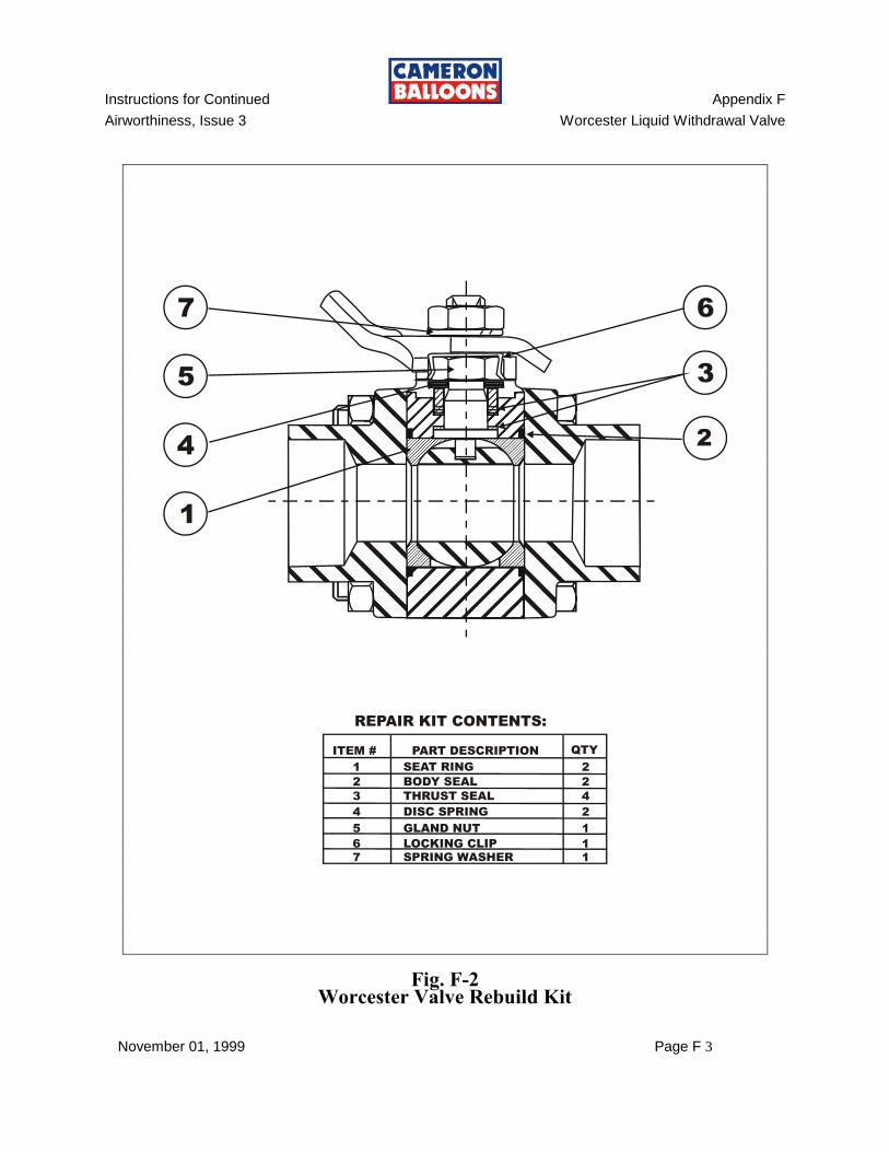
2) There is a repair kit available for the Worcester valve. See Fig. F-2.
Instructions for Continued Appendix F
Airworthiness, Issue 3 Worcester Liquid Withdrawal Valve
November 01, 1999 Page F 2
Fig. F-1 Worcester Liquid Withdrawal Valve,
Rego and Tema Style
Instructions for Continued Appendix F
Airworthiness, Issue 3 Worcester Liquid Withdrawal Valve
November 01, 1999 Page F 3
Fig. F-2 Worcester Valve Rebuild Kit

Instructions for Continued Appendix F
Airworthiness, Issue 3 Worcester Liquid Withdrawal Valve
November 01, 1999 Page F 4
THIS PAGE INTENTIONALLY BLANK

Instructions for Continued Appendix G
Airworthiness, Issue 3 Sirocco Burner
January 01, 2001 Page 1 of 32
SIROCCO BURNER A) PREVENTIVE MAINTENANCE, in addition to that listed in
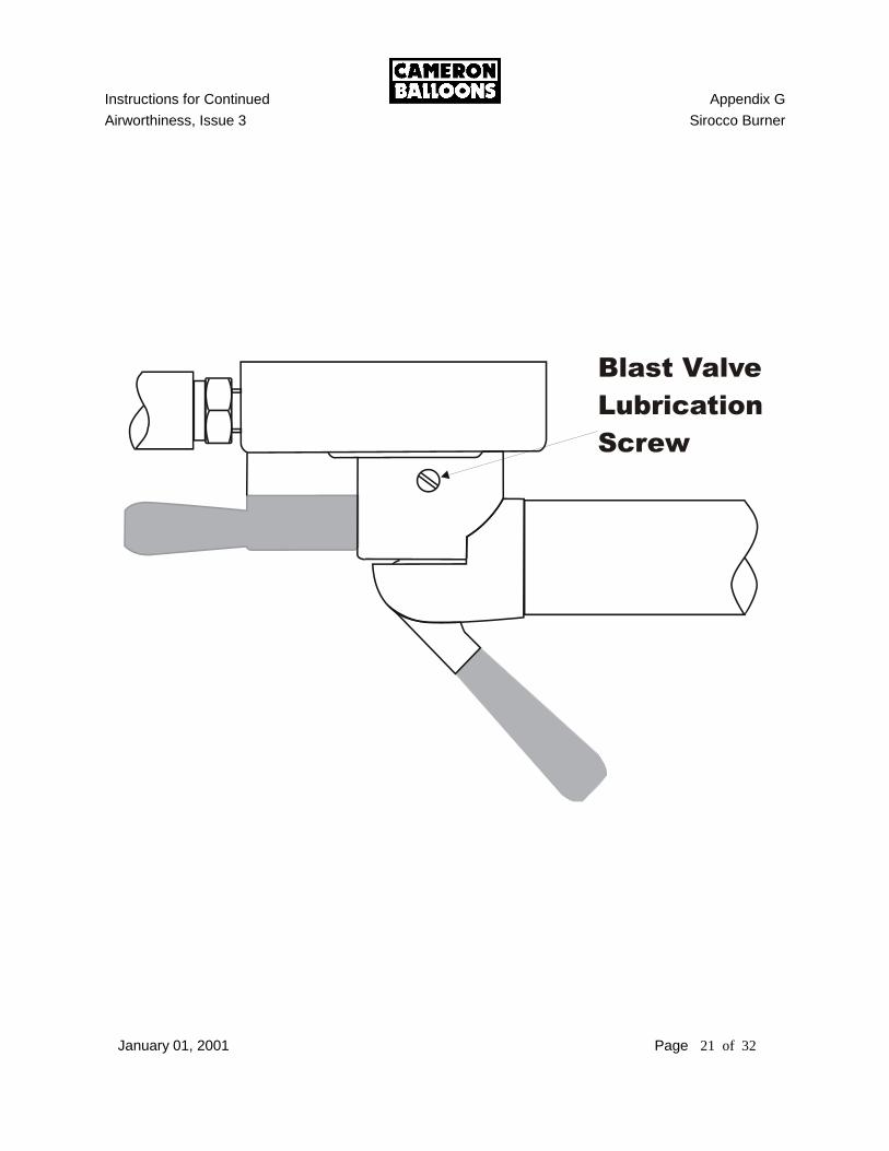
Section 2.4: 1) Lubrication of the Main Blast Valve through the lubrication port. The main blast
valve should be lubricated through the port every 10 hours of flight time. See Section E 1.
2) The pilot light inlet filter may be removed and cleaned. See Section H.
B) REQUIRED MAINTENANCE at Annual/100 hour Inspections:
1) Blast valve stem O-ring replacement is NOT a required Annual/100 Hour Inspection procedure. The O-rings must be replaced only if damaged. However, the blast valve must be disassembled, all internal parts cleaned and inspected and the valve stem o-rings lubricated with silicone grease. See Section E.
2) The pilot light inlet filter must be cleaned. See Section H. 3) The pilot light outlet jet and filter must be cleaned. See Section G. 4) The pilot light regulators must be disassembled, cleaned and inspected. See
Section G.
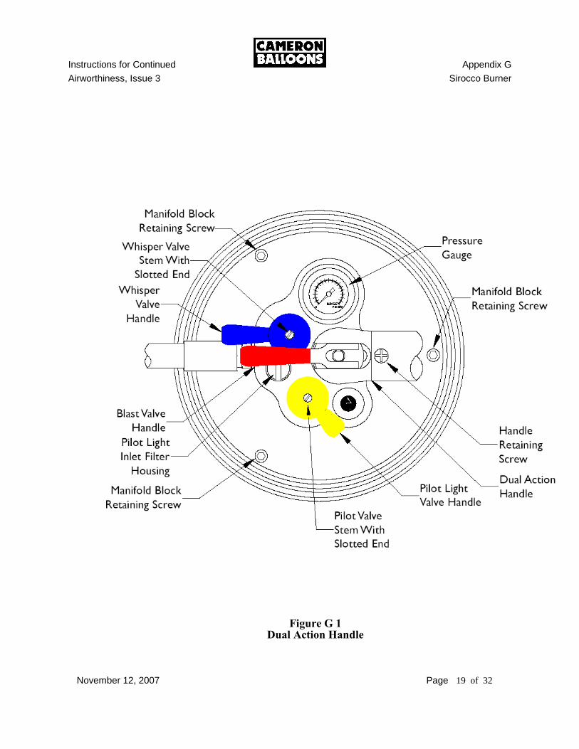
C) HANDLE: The Sirocco is available with two types of handle. One is the ‘Cross Bar Handle’
and the other is the ‘Dual Action Handle’. The ‘Dual Action Handle’ enables both burners to be operated with one hand.
1) HANDLE REMOVAL - DUAL ACTION: See Figure G 1 a) Use a large Philips screwdriver to remove the handle retaining screws. b) Move the blast valve handles as necessary and remove the Dual Action
Handle.
Instructions for Continued Appendix G
Airworthiness, Issue 3 Sirocco Burner
January 01, 2001 Page 2 of 32
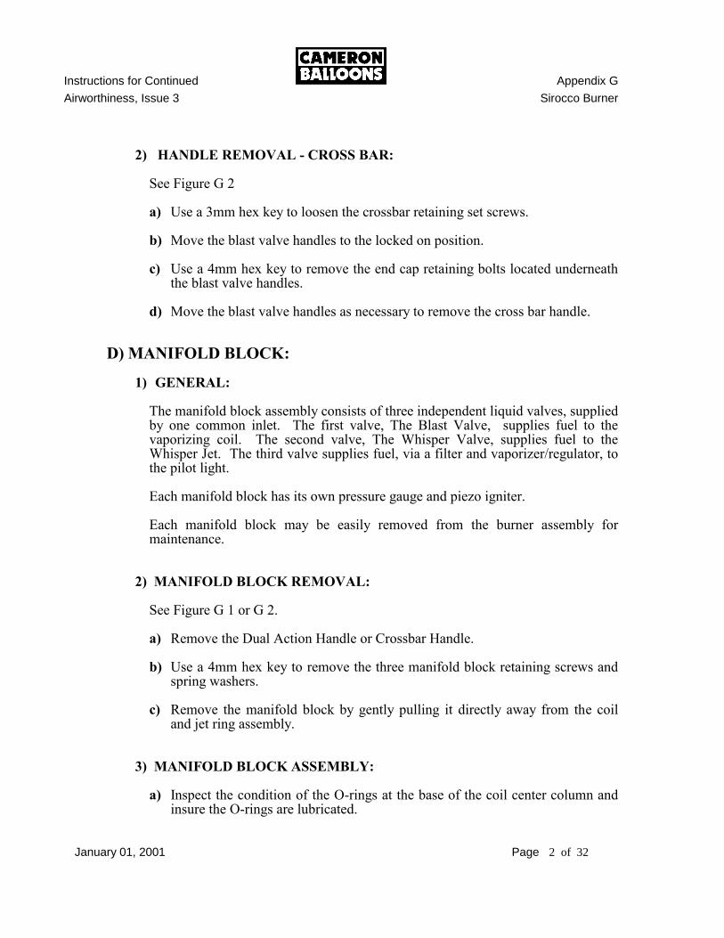
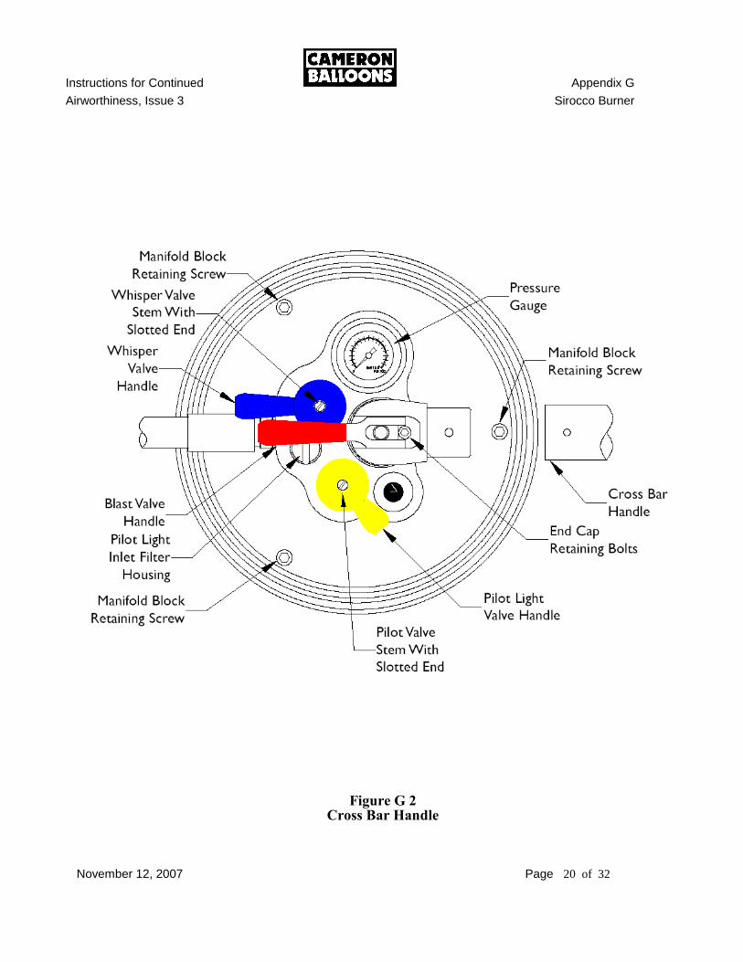
2) HANDLE REMOVAL - CROSS BAR: See Figure G 2 a) Use a 3mm hex key to loosen the crossbar retaining set screws. b) Move the blast valve handles to the locked on position. c) Use a 4mm hex key to remove the end cap retaining bolts located underneath
the blast valve handles. d) Move the blast valve handles as necessary to remove the cross bar handle.
D) MANIFOLD BLOCK: 1) GENERAL: The manifold block assembly consists of three independent liquid valves, supplied
by one common inlet. The first valve, The Blast Valve, supplies fuel to the vaporizing coil. The second valve, The Whisper Valve, supplies fuel to the Whisper Jet. The third valve supplies fuel, via a filter and vaporizer/regulator, to the pilot light.
Each manifold block has its own pressure gauge and piezo igniter. Each manifold block may be easily removed from the burner assembly for
maintenance. 2) MANIFOLD BLOCK REMOVAL: See Figure G 1 or G 2. a) Remove the Dual Action Handle or Crossbar Handle. b) Use a 4mm hex key to remove the three manifold block retaining screws and
spring washers. c) Remove the manifold block by gently pulling it directly away from the coil
and jet ring assembly. 3) MANIFOLD BLOCK ASSEMBLY: a) Inspect the condition of the O-rings at the base of the coil center column and
insure the O-rings are lubricated.
Instructions for Continued Appendix G
Airworthiness, Issue 3 Sirocco Burner
January 01, 2001 Page 3 of 32
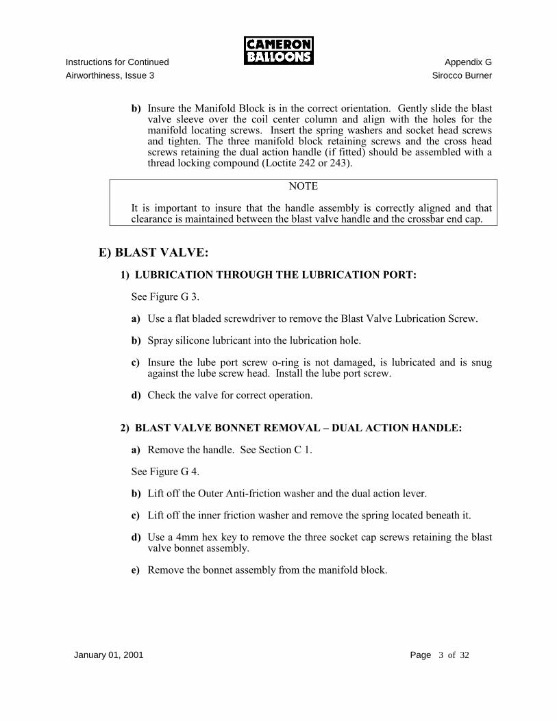
b) Insure the Manifold Block is in the correct orientation. Gently slide the blast valve sleeve over the coil center column and align with the holes for the manifold locating screws. Insert the spring washers and socket head screws and tighten. The three manifold block retaining screws and the cross head screws retaining the dual action handle (if fitted) should be assembled with a thread locking compound (Loctite 242 or 243).
NOTE
It is important to insure that the handle assembly is correctly aligned and that
clearance is maintained between the blast valve handle and the crossbar end cap.
E) BLAST VALVE: 1) LUBRICATION THROUGH THE LUBRICATION PORT: See Figure G 3. a) Use a flat bladed screwdriver to remove the Blast Valve Lubrication Screw. b) Spray silicone lubricant into the lubrication hole. c) Insure the lube port screw o-ring is not damaged, is lubricated and is snug
against the lube screw head. Install the lube port screw. d) Check the valve for correct operation. 2) BLAST VALVE BONNET REMOVAL – DUAL ACTION HANDLE: a) Remove the handle. See Section C 1. See Figure G 4. b) Lift off the Outer Anti-friction washer and the dual action lever. c) Lift off the inner friction washer and remove the spring located beneath it. d) Use a 4mm hex key to remove the three socket cap screws retaining the blast
valve bonnet assembly. e) Remove the bonnet assembly from the manifold block.

Instructions for Continued Appendix G
Airworthiness, Issue 3 Sirocco Burner
January 01, 2001 Page 4 of 32
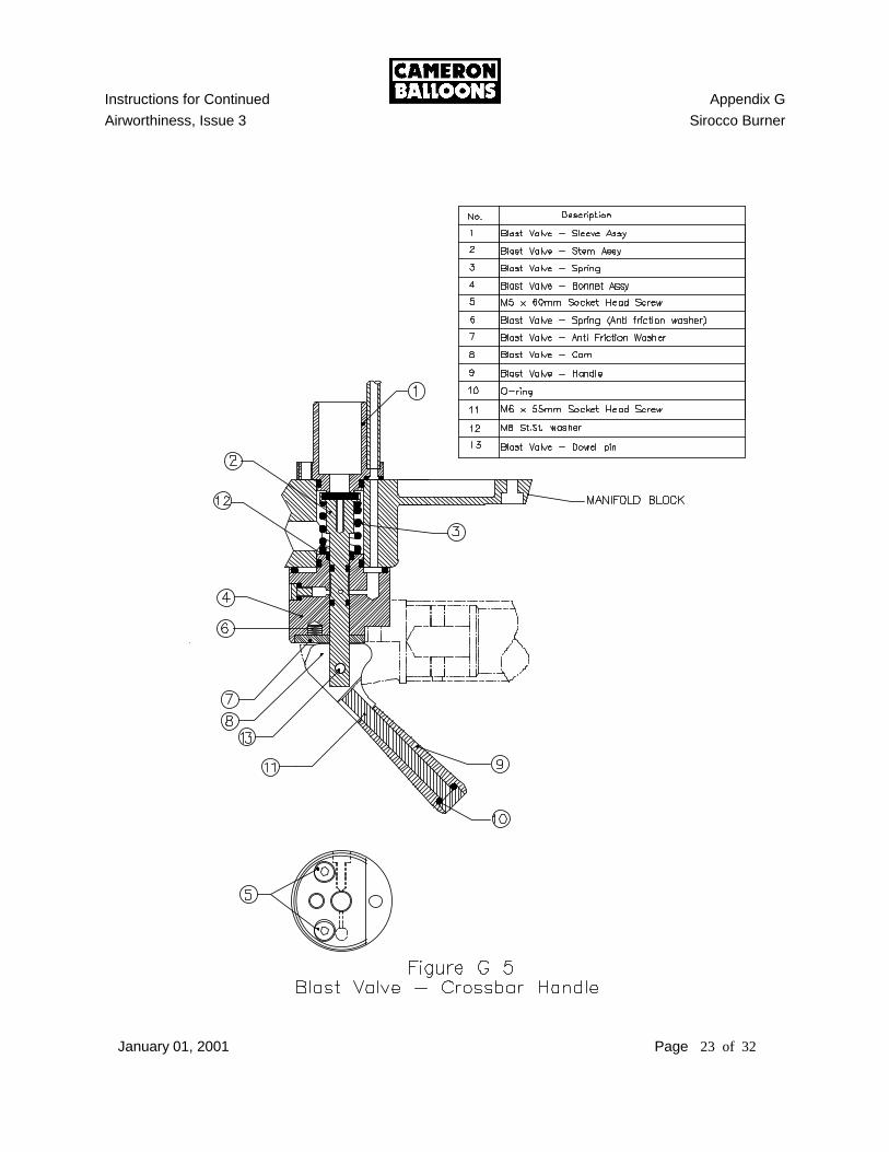
3) BLAST VALVE BONNET REMOVAL – CROSSBAR HANDLE: a) Remove the handle. See Section C 2. See Figure G 5. b) Lift off the anti-friction washer and remove the spring located beneath it. c) Use a 4mm hex key to remove the two bolts retaining the blast valve bonnet
assembly and remove it from the manifold block. 4) BLAST VALVE STEM & O-RING MAINTENANCE: See Figure G 5. a) Remove the valve stem, spring and stainless steel washer from the valve
bonnet. b) Clean the stem with a soft cloth. c) Inspect the O-rings and seal pad for damage. d) If the O-rings are damaged they must be replaced. e) If the stem or seal pad are damaged, the stem must be replaced. f) Lubricate the stem and O-rings with silicone grease. 5) BLAST VALVE BONNET MAINTENANCE: See Figure G 5. a) Remove and inspect the two O-rings and PTFE spring seal from the upper face
of the bonnet. Replace if damaged. b) Remove the lubrication port screw and inspect the O-ring. Replace if
damaged. c) Clean and inspect the bonnet for wear and scoring in the bonnet bore. d) Lightly lubricate the spring seal and O-rings. e) Insure that the spring seal has the open face away from the bonnet with the
spring visible. f) Replace the Lubrication port screw.
Instructions for Continued Appendix G
Airworthiness, Issue 3 Sirocco Burner
January 01, 2001 Page 5 of 32
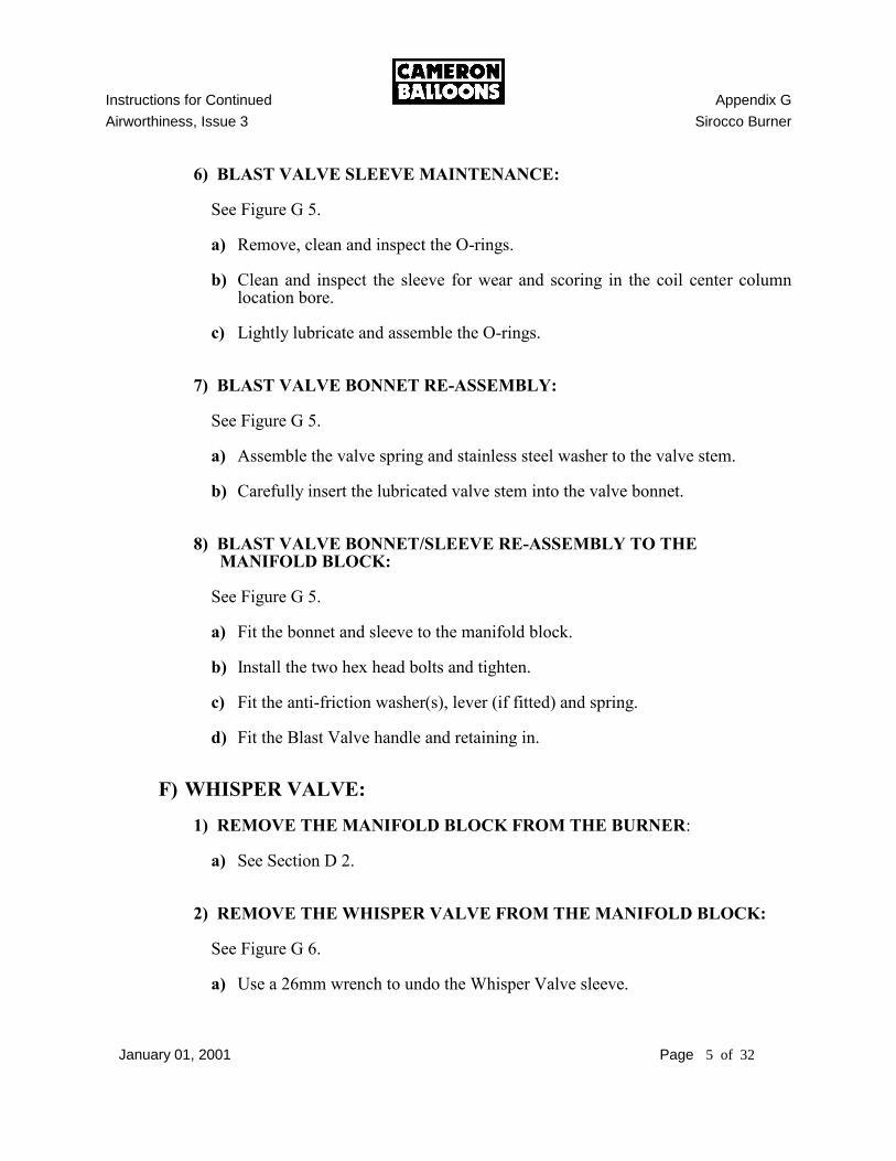
6) BLAST VALVE SLEEVE MAINTENANCE: See Figure G 5. a) Remove, clean and inspect the O-rings. b) Clean and inspect the sleeve for wear and scoring in the coil center column
location bore. c) Lightly lubricate and assemble the O-rings. 7) BLAST VALVE BONNET RE-ASSEMBLY: See Figure G 5. a) Assemble the valve spring and stainless steel washer to the valve stem. b) Carefully insert the lubricated valve stem into the valve bonnet. 8) BLAST VALVE BONNET/SLEEVE RE-ASSEMBLY TO THE MANIFOLD BLOCK: See Figure G 5. a) Fit the bonnet and sleeve to the manifold block. b) Install the two hex head bolts and tighten. c) Fit the anti-friction washer(s), lever (if fitted) and spring. d) Fit the Blast Valve handle and retaining in.
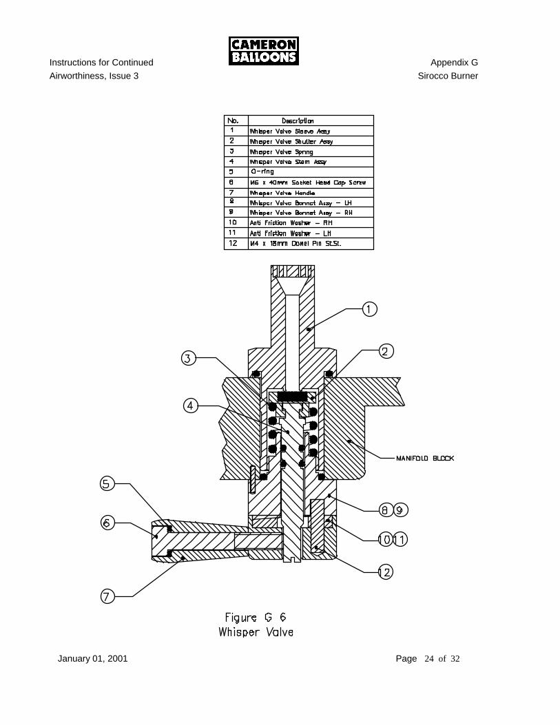
F) WHISPER VALVE: 1) REMOVE THE MANIFOLD BLOCK FROM THE BURNER: a) See Section D 2. 2) REMOVE THE WHISPER VALVE FROM THE MANIFOLD BLOCK: See Figure G 6. a) Use a 26mm wrench to undo the Whisper Valve sleeve.
Instructions for Continued Appendix G
Airworthiness, Issue 3 Sirocco Burner
January 01, 2001 Page 6 of 32
b) Remove the sleeve from the upper surface. c) Remove the bonnet, stem assembly and handle from the lower surface. 3) DISASSEMBLY OF WHISPER VALVE BONNET AND STEM ASSEMBLY: See Figure G 6. a) Use a 5mm hex key to loosen the valve handle. b) Use a flat blade screwdriver to turn the stem in a clockwise direction until the
stem separates from the handle. c) Remove the valve stem, valve shutter and spring from the valve bonnet. 4) WHISPER VALVE STEM MAINTENANCE: See Figure G 6. a) Clean and inspect the stem, stem O-rings and Shutter. b) If the Shutter or O-rings are damaged they must be replaced. c) Lubricate the stem and O-rings with silicone grease. 5) WHISPER VALVE BONNET ASSEMBLY MAINTENANCE: See Figure G 6. a) Inspect the O-ring from the upper face of the bonnet. Replace if necessary. b) Inspect the bonnet bore for wear and scoring. 6) WHISPER VALVE SLEEVE ASSEMBLY MAINTENANCE: See Figure G 6. a) Remove and inspect the O-ring. b) Clean the sleeve. c) Inspect the sleeve for wear, scoring and thread integrity. d) Check that the jet plate is secure.
Instructions for Continued Appendix G
Airworthiness, Issue 3 Sirocco Burner
January 01, 2001 Page 7 of 32
7) WHISPER VALVE RE-ASSEMBLY: See Figure G 6. a) Assemble the valve spring and valve shutter to the valve stem. b) Insert the lubricated valve stem into the valve bonnet. c) Use a flat blade screwdriver to turn the valve stem in an anti-clockwise
direction until the base of the stem is parallel with the base of the handle. d) Use a 4mm hex key to temporarily re-tighten the handle. e) Insert the bonnet assembly in the base of the manifold block. Insure that the
spring pin is in its location hole. f) Install the whisper valve sleeve to the bonnet and tighten. g) Install the manifold block and handle to the burner. 8) WHISPER VALVE ADJUSTMENT: See Figure G 1 or G 2. If the valve fails to turn on or shut off satisfactorily, it may be adjusted as follows: a) Turn the whisper valve handle to the open position. b) Loosen the whisper valve handle bolt with a 5mm hex key. The threaded
valve stem has two flats that are parallel with the screwdriver slot. c) Use a flat blade screwdriver (5mm blade) to turn the stem of the whisper valve
1/2 turn clockwise (in) if the valve is not shutting off or 1/2 turn counter-clockwise (out) if the valve is not turning on.
d) One of the flats on the stem should now be perpendicular to the valve handle. e) Tighten the valve handle screw against the flat ONLY, not the threads. f) Check the action of the valve and repeat as necessary.
NOTE: The valve handle should have approximately 15º to 20º of free movement before the valve opens.
Instructions for Continued Appendix G
Airworthiness, Issue 3 Sirocco Burner
January 01, 2001 Page 8 of 32
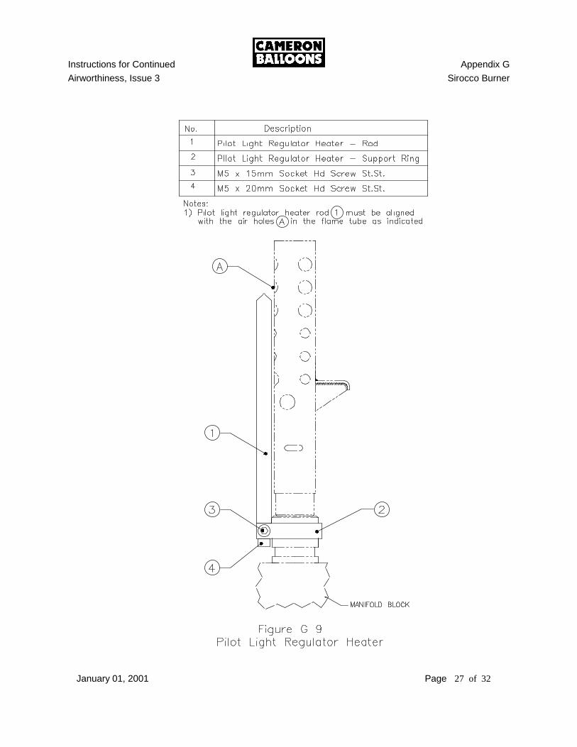
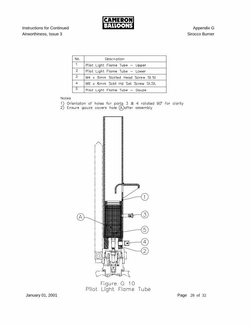
G) PILOT LIGHT AND REGULATOR: 1) REMOVE THE MANIFOLD BLOCK FROM THE BURNER: a) See Section D 2. 2) PILOT LIGHT FLAME TUBE, REGULATOR HEATER & REGULATOR
DISASSEMBLY: See Figure G 8 through G 10 a) Note the relative position of the regulator heater with regard to the other
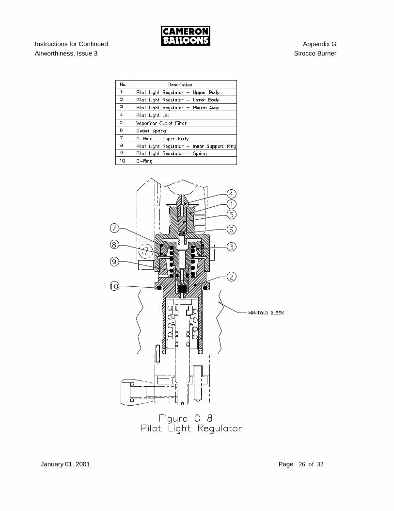
components of the burner. b) Use a 3mm hex key to undo and remove the pilot light flame tube. c) Use a 4mm hex key to undo and remove the pilot light regulator heater. d) Restrain the regulator lower body. e) Use a 26mm wrench to remove the regulator upper body. f) Carefully remove the piston assembly and spring from the upper body. g) Remove the brass support ring from the regulator bore. h) Remove the jet from the housing. i) Remove the regulator outlet filter and spring from the housing. 3) FLAME TUBE AND HEATER MAINTENANCE: See Figure G 9 through G 10 a) Mark the upper and lower flame tube to insure that the alignment can be
recreated during re-assembly. b) Remove the upper flame tube retaining screw and disassemble the upper and
lower flame tube and gauze. c) Thoroughly clean the upper and lower flame tubes. d) Inspect the gauze and internal mesh in the lower flame tube. If either is
damaged they must be replaced. e) Inspect the heater for signs of erosion or overheating. The length of the heater
rod should be 150mm.
Instructions for Continued Appendix G
Airworthiness, Issue 3 Sirocco Burner
January 01, 2001 Page 9 of 32
f) If the rod must be replaced, the socket head cap screw should be treated with
Loctite 270 or equivalent thread locking compound before tightening. 4) FLAME TUBE AND HEATER REASSEMBLY: See Figure G 9 through G 10 a) Re-assembly is the reverse order of removal. Check the alignment of the
components before installing the manifold block to the burner. 5) PILOT LIGHT REGULATOR MAINTENANCE: See Figure G 9. a) Carefully clean the support ring and the inside of the regulator with a soft lint
free cloth. b) Inspect the piston sealing O-ring. c) Carefully clean the piston with a lint free cloth. If the housing or piston are
heavily soiled they may be cleaned with solvent. d) Inspect the piston stem O-ring and seal, replace as necessary. e) Inspect the outlet jet, filter and spring, replace as necessary. 6) PILOT LIGHT REGULATOR RE-ASSEMBLY: See Figure G 9. a) Install the jet, outlet filter and spring in the housing. Make sure the spring is
under the filter. b) Lightly lubricate the piston sealing O-ring with silicone spray. c) Install the brass support ring. d) Lightly lubricate the piston stem O-ring with silicone spray. e) Carefully install the piston in the upper body. f) Install the spring. g) Install the upper regulator assembly to the lower body.
Instructions for Continued Appendix G
Airworthiness, Issue 3 Sirocco Burner
January 01, 2001 Page 10 of 32
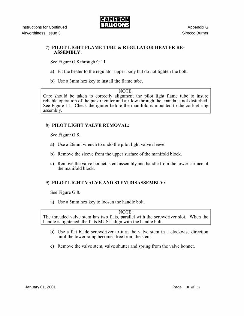
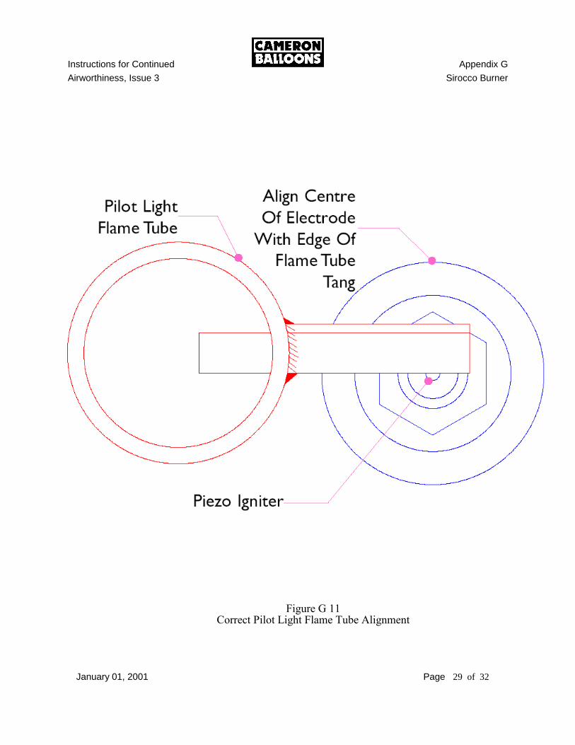
7) PILOT LIGHT FLAME TUBE & REGULATOR HEATER RE-ASSEMBLY:
See Figure G 8 through G 11 a) Fit the heater to the regulator upper body but do not tighten the bolt. b) Use a 3mm hex key to install the flame tube.
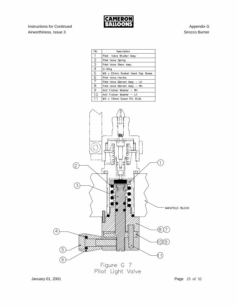
NOTE: Care should be taken to correctly alignment the pilot light flame tube to insure reliable operation of the piezo igniter and airflow through the coanda is not disturbed. See Figure 11. Check the igniter before the manifold is mounted to the coil/jet ring assembly. 8) PILOT LIGHT VALVE REMOVAL: See Figure G 8. a) Use a 26mm wrench to undo the pilot light valve sleeve. b) Remove the sleeve from the upper surface of the manifold block. c) Remove the valve bonnet, stem assembly and handle from the lower surface of
the manifold block. 9) PILOT LIGHT VALVE AND STEM DISASSEMBLY: See Figure G 8. a) Use a 5mm hex key to loosen the handle bolt.
NOTE: The threaded valve stem has two flats, parallel with the screwdriver slot. When the handle is tightened, the flats MUST align with the handle bolt. b) Use a flat blade screwdriver to turn the valve stem in a clockwise direction
until the lower ramp becomes free from the stem. c) Remove the valve stem, valve shutter and spring from the valve bonnet.
Instructions for Continued Appendix G
Airworthiness, Issue 3 Sirocco Burner
January 01, 2001 Page 11 of 32
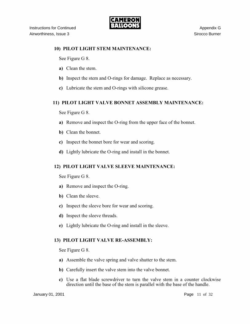
10) PILOT LIGHT STEM MAINTENANCE: See Figure G 8. a) Clean the stem. b) Inspect the stem and O-rings for damage. Replace as necessary. c) Lubricate the stem and O-rings with silicone grease. 11) PILOT LIGHT VALVE BONNET ASSEMBLY MAINTENANCE: See Figure G 8. a) Remove and inspect the O-ring from the upper face of the bonnet. b) Clean the bonnet. c) Inspect the bonnet bore for wear and scoring. d) Lightly lubricate the O-ring and install in the bonnet. 12) PILOT LIGHT VALVE SLEEVE MAINTENANCE: See Figure G 8. a) Remove and inspect the O-ring. b) Clean the sleeve. c) Inspect the sleeve bore for wear and scoring. d) Inspect the sleeve threads. e) Lightly lubricate the O-ring and install in the sleeve. 13) PILOT LIGHT VALVE RE-ASSEMBLY: See Figure G 8. a) Assemble the valve spring and valve shutter to the stem. b) Carefully insert the valve stem into the valve bonnet. c) Use a flat blade screwdriver to turn the valve stem in a counter clockwise
direction until the base of the stem is parallel with the base of the handle.
Instructions for Continued Appendix G
Airworthiness, Issue 3 Sirocco Burner
January 01, 2001 Page 12 of 32
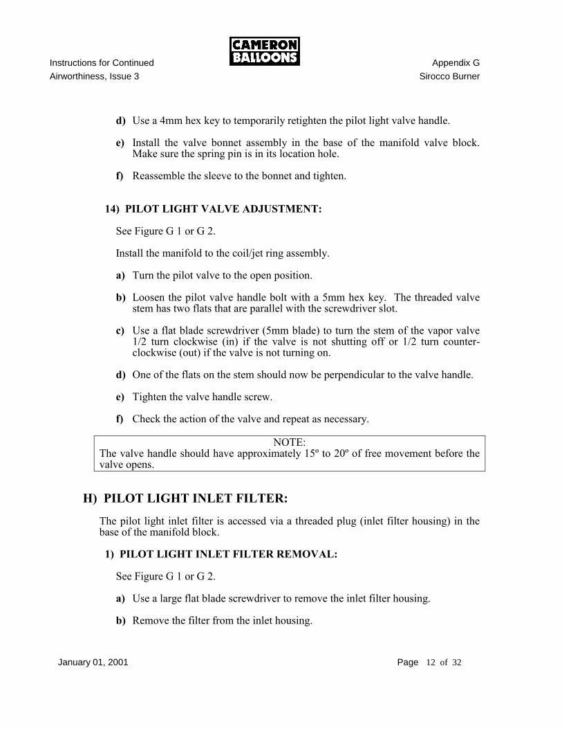
d) Use a 4mm hex key to temporarily retighten the pilot light valve handle. e) Install the valve bonnet assembly in the base of the manifold valve block.
Make sure the spring pin is in its location hole. f) Reassemble the sleeve to the bonnet and tighten. 14) PILOT LIGHT VALVE ADJUSTMENT: See Figure G 1 or G 2. Install the manifold to the coil/jet ring assembly. a) Turn the pilot valve to the open position. b) Loosen the pilot valve handle bolt with a 5mm hex key. The threaded valve
stem has two flats that are parallel with the screwdriver slot. c) Use a flat blade screwdriver (5mm blade) to turn the stem of the vapor valve
1/2 turn clockwise (in) if the valve is not shutting off or 1/2 turn counter-clockwise (out) if the valve is not turning on.
d) One of the flats on the stem should now be perpendicular to the valve handle. e) Tighten the valve handle screw. f) Check the action of the valve and repeat as necessary.
NOTE: The valve handle should have approximately 15º to 20º of free movement before the valve opens.
H) PILOT LIGHT INLET FILTER: The pilot light inlet filter is accessed via a threaded plug (inlet filter housing) in the base of the manifold block. 1) PILOT LIGHT INLET FILTER REMOVAL: See Figure G 1 or G 2. a) Use a large flat blade screwdriver to remove the inlet filter housing. b) Remove the filter from the inlet housing.

Instructions for Continued Appendix G
Airworthiness, Issue 3 Sirocco Burner
January 01, 2001 Page 13 of 32
2) PILOT LIGHT INLET FILTER MAINTENANCE: a) Clean the filter with solvent or replace as necessary. b) Inspect the housing o-ring and place it in the inlet filter housing. c) Lubricate the o-ring with silicone grease. 3) PILOT LIGHT INLET FILTER RE-ASSEMBLY: See Figure G 1 or G 2. a) Replace the inlet filter housing in the manifold block and tighten.
I) PILOT LIGHT JET & OUTLET FILTER See Figure G 8. 1) PILOT LIGHT JET & OUTLET FILTER REMOVAL a) Remove the manifold block. See Section D 2. b) Use a 3mm hex key to loosen the allen screw (4) and remove the pilot light
flame cup. c) The jet (1) is now visible and may be removed with a 1/4” nut-driver or
wrench. d) Invert the manifold block assembly and the filter (5) and spring will drop
clear. 2) PILOT LIGHT JET & OUTLET FILTER RE-ASSEMBLY See Figure G 8 and G 11. a) Assembly is the reverse of the above procedure. c) Care should be taken to insure the correct alignment of the pilot light flame
tube to insure reliable operation of the piezo igniter. d) The operation of the piezo igniter should be checked before the manifold
block is assembled to the coil.
Instructions for Continued Appendix G
Airworthiness, Issue 3 Sirocco Burner
January 01, 2001 Page 14 of 32
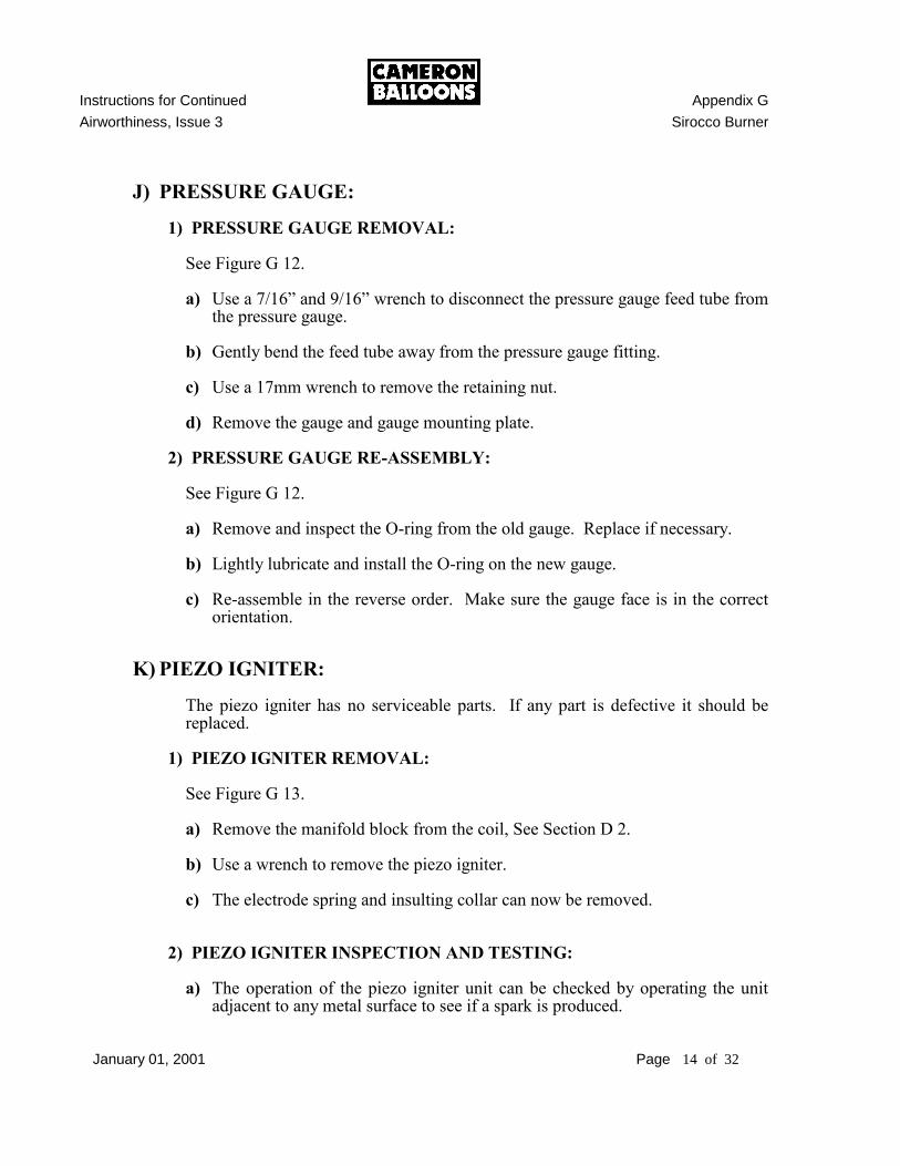
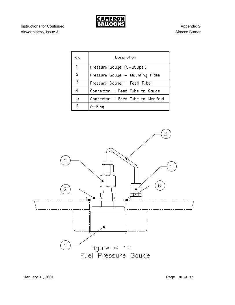
J) PRESSURE GAUGE:
1) PRESSURE GAUGE REMOVAL: See Figure G 12. a) Use a 7/16” and 9/16” wrench to disconnect the pressure gauge feed tube from
the pressure gauge. b) Gently bend the feed tube away from the pressure gauge fitting. c) Use a 17mm wrench to remove the retaining nut. d) Remove the gauge and gauge mounting plate. 2) PRESSURE GAUGE RE-ASSEMBLY: See Figure G 12. a) Remove and inspect the O-ring from the old gauge. Replace if necessary. b) Lightly lubricate and install the O-ring on the new gauge. c) Re-assemble in the reverse order. Make sure the gauge face is in the correct
orientation.
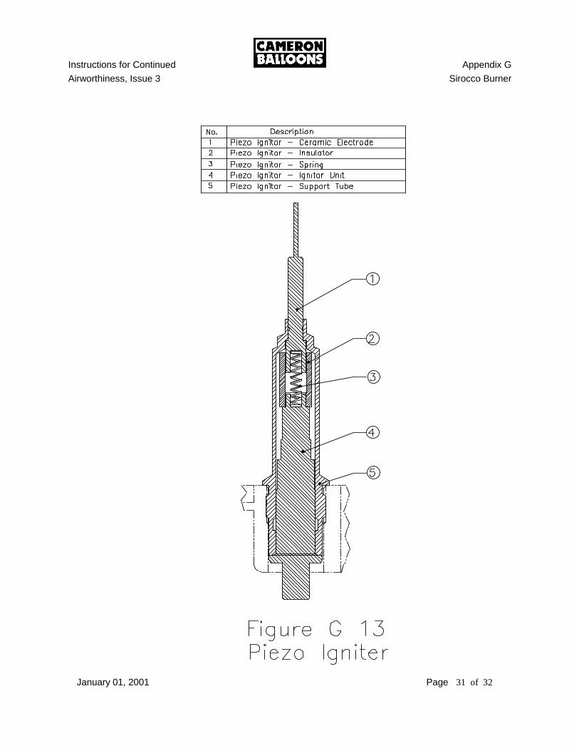
K) PIEZO IGNITER: The piezo igniter has no serviceable parts. If any part is defective it should be
replaced. 1) PIEZO IGNITER REMOVAL: See Figure G 13. a) Remove the manifold block from the coil, See Section D 2. b) Use a wrench to remove the piezo igniter. c) The electrode spring and insulting collar can now be removed. 2) PIEZO IGNITER INSPECTION AND TESTING: a) The operation of the piezo igniter unit can be checked by operating the unit
adjacent to any metal surface to see if a spark is produced.
Instructions for Continued Appendix G
Airworthiness, Issue 3 Sirocco Burner
January 01, 2001 Page 15 of 32
b) The electrode and insulting collar should be checked for damage.
Instructions for Continued Appendix G
Airworthiness, Issue 3 Sirocco Burner
January 01, 2001 Page 16 of 32
3) PIEZO IGNITER RE-ASSEMBLY: See Figure G 13. a) Re-assemble in reverse order.
NOTE For ease of assembly it is recommended that the burner be held in the vertical
position with the coil pointing upwards. The components can then be balanced on top of the igniter unit before insertion.
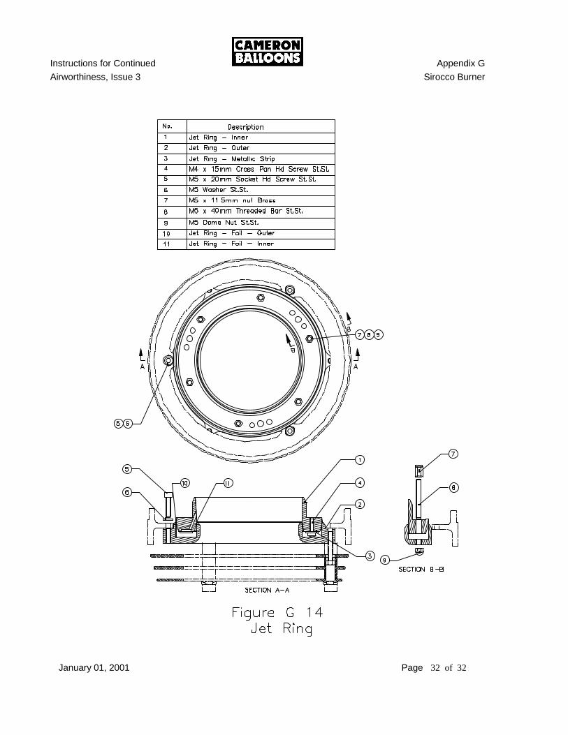
L) JET RING:
1) GENERAL: The jet ring is formed from an annular ‘U’ section outer into which the inner jet
ring locates. Two annular foils are located between the inner and outer sections which effectively control the nozzle area. In addition, the inner jet ring is equipped with nine metal strips, which, when operating with low fuel pressure, deflect to open nine auxiliary nozzles. This maintains power output at low fuel pressures.
IMPORTANT:
The jet ring assembly and supports should be marked with a felt tipped pen prior to disassembly. This will insure the burner is rebuilt in the correct orientation. This operation should be repeated before splitting the inner and outer jet ring and removing the inner jet ring from the coil.
2) JET RING DISASSEMBLY: a) Remove the manifold block assembly from the burner. See Section D 2. See Figure G 14. b) Use a 8mm wrench to remove the 6 brass nuts which attach the upper jet ring
to the lower jet ring. c) Use a 4mm hex key to remove the three hex bolts that attach the outer jet ring
and support assembly to the outer jet ring support. d) Remove the outer jet ring and support assembly from the burner.
NOTE: It may be necessary to lightly tap the jet ring retaining bolts with a soft faced
hammer to free the lower jet ring from the upper jet ring. e) Use a 4mm hex key to remove the six hex bolts attching the inner jet ring to
the coil.
Instructions for Continued Appendix G
Airworthiness, Issue 3 Sirocco Burner
January 01, 2001 Page 17 of 32
3) INNER JET RING MAINTENANCE: a) Use a large Philips screwdriver to remove the metal strips from the inner jet
ring. b) Clean the inner jet ring. c) Install the metal strips. Use Loctite 222 or equivalent.
NOTE: Insure the metal strips are installed with the part designation (i.e. the writing)
facing away from the jet ring. d) Use a 0.1mm feeler gauge to check around the free edges of each metal strip to
insure correct sealing of the strips. It should not be possible to insert the feeler gauge underneath the strip.
If any strip fails the above test it may be removed and gently hammered flat
with a nylon faced hammer. The strip should can then be reinstalled and checked again.
e) Use a heat gun to gently heat (Maximum of 212° F) the base of the jet ring.
The free end of the strips will visibly deflect away from the jet ring. 4) OUTER JET RING MAINTENANCE: a) Remove and clean the inner and outer jet foils. b) Clean the outer jet ring assembly. c) Remove the six retaining nuts. d) Clean the studs to remove old thread sealant. e) Install the retaining nuts. Use Loctite 270 or equivalent. 5) COIL END FITTING O-RINGS: a) Clean and inspect the three center column O-rings. Replace as necessary. b) Clean and inspect the three coil to jet ring O-rings. Replace as necessary. c) Lubricate lightly with silicone grease before installation.
Instructions for Continued Appendix G
Airworthiness, Issue 3 Sirocco Burner
January 01, 2001 Page 18 of 32
6) JET RING RE-ASSEMBLY: See Figure G 14. a) Use a 4mm hex key to install the inner jet ring to the coil. Use Loctite 222 or
equivalent. b) Install the inner and outer jet foils in the outer jet ring and assemble to the
inner jet ring. The jet foils should be protruding evenly around the inner and outer jet ring. This is best achieved by assembling the jet ring to the burner in the upright position.
c) Use an 8mm socket to install loosely the 6 brass nuts which attach the upper
jet ring to the lower jet ring. DO NOT TIGHTEN THE NUTS d) Use a 4mm hex key to assemble loosely the outer jet ring and support
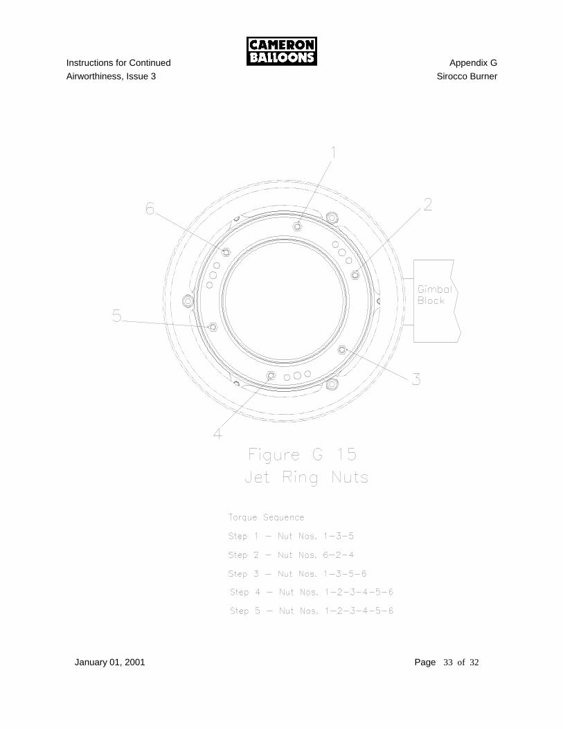
assembly to the outer jet ring support. DO NOT TIGHTEN THE BOLTS e) Install the manifold to the burner and the handle to the manifold block. 7) TIGHTENING THE JET RING: a) Insure the jet foils are correctly located in the jet ring. The jet foils should be
protruding evenly around the inner and outer jet ring. This is best achieved by assembling the jet ring to the burner in the upright position.
b) Tighten gradually the six brass nuts on the jet ring in the following order. Step 1 Nut #’s 1 – 3 – 5 (See Figure G 15 for nut numbering) Step 2 Nut #’s 6 – 2 – 4 Step 3 Nut #’s 1 – 3 – 5 – 6 Step 4 Nut #’s 1 – 2 – 3 – 4 – 5 – 6 Step 5 Nut #’s 1 – 2 – 3 – 4 – 5 – 6 Step 5 should be repeated until 6 Nm (53 lb in) is obtained and there is no
variation in torque detected. If a constant torque cannot be achieved, the outer jet ring stud retaining nuts should be loosened and then re-tightened until the proper torque and feel are correct.
Tightening to this valve should result in a blue flame with very little yellow flame
at the annular baffle (slotted stainless steel ring).
Instructions for Continued Appendix G
Airworthiness, Issue 3 Sirocco Burner
November 12, 2007 Page 19 of 32
Figure G 1 Dual Action Handle
Instructions for Continued Appendix G
Airworthiness, Issue 3 Sirocco Burner
November 12, 2007 Page 20 of 32
Figure G 2 Cross Bar Handle
Instructions for Continued Appendix G
Airworthiness, Issue 3 Sirocco Burner
January 01, 2001 Page 21 of 32

Instructions for Continued Appendix G
Airworthiness, Issue 3 Sirocco Burner
January 01, 2001 Page 22 of 32
Instructions for Continued Appendix G
Airworthiness, Issue 3 Sirocco Burner
January 01, 2001 Page 23 of 32
Instructions for Continued Appendix G
Airworthiness, Issue 3 Sirocco Burner
January 01, 2001 Page 24 of 32
Instructions for Continued Appendix G
Airworthiness, Issue 3 Sirocco Burner
January 01, 2001 Page 25 of 32
Instructions for Continued Appendix G
Airworthiness, Issue 3 Sirocco Burner
January 01, 2001 Page 26 of 32
Instructions for Continued Appendix G
Airworthiness, Issue 3 Sirocco Burner
January 01, 2001 Page 27 of 32
Instructions for Continued Appendix G
Airworthiness, Issue 3 Sirocco Burner
January 01, 2001 Page 28 of 32
Instructions for Continued Appendix G
Airworthiness, Issue 3 Sirocco Burner
January 01, 2001 Page 29 of 32
Figure G 11 Correct Pilot Light Flame Tube Alignment
Instructions for Continued Appendix G
Airworthiness, Issue 3 Sirocco Burner
January 01, 2001 Page 30 of 32
Instructions for Continued Appendix G
Airworthiness, Issue 3 Sirocco Burner
January 01, 2001 Page 31 of 32
Instructions for Continued Appendix G
Airworthiness, Issue 3 Sirocco Burner
January 01, 2001 Page 32 of 32
Instructions for Continued Appendix G
Airworthiness, Issue 3 Sirocco Burner
January 01, 2001 Page 33 of 32
Instructions for Continued Appendix H
Airworthiness, Issue 3 Fuel Tank Damage Inspection,
Damage Limits and Re-qualification
November 12, 2007 Page 1 of 5
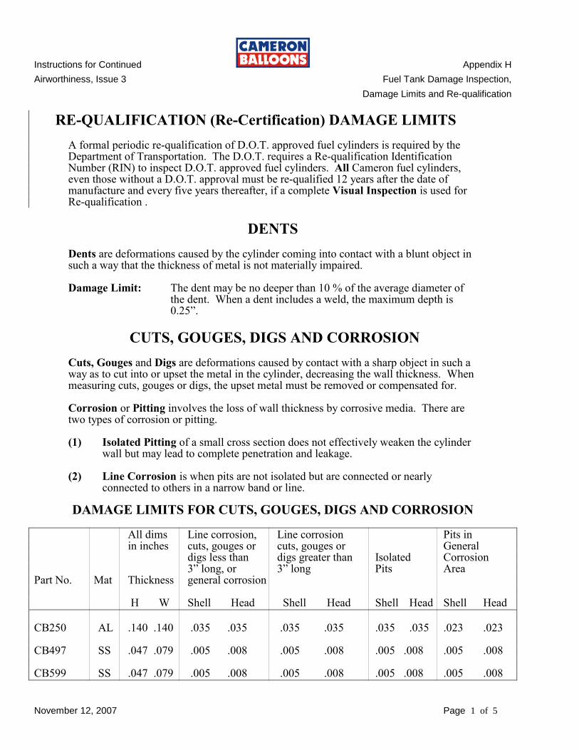
RE-QUALIFICATION (Re-Certification) DAMAGE LIMITS A formal periodic re-qualification of D.O.T. approved fuel cylinders is required by the
Department of Transportation. The D.O.T. requires a Re-qualification Identification Number (RIN) to inspect D.O.T. approved fuel cylinders. All Cameron fuel cylinders, even those without a D.O.T. approval must be re-qualified 12 years after the date of manufacture and every five years thereafter, if a complete Visual Inspection is used for Re-qualification .
DENTS Dents are deformations caused by the cylinder coming into contact with a blunt object in such a way that the thickness of metal is not materially impaired. Damage Limit: The dent may be no deeper than 10 % of the average diameter of
the dent. When a dent includes a weld, the maximum depth is 0.25”.
CUTS, GOUGES, DIGS AND CORROSION Cuts, Gouges and Digs are deformations caused by contact with a sharp object in such a way as to cut into or upset the metal in the cylinder, decreasing the wall thickness. When measuring cuts, gouges or digs, the upset metal must be removed or compensated for. Corrosion or Pitting involves the loss of wall thickness by corrosive media. There are two types of corrosion or pitting. (1) Isolated Pitting of a small cross section does not effectively weaken the cylinder
wall but may lead to complete penetration and leakage. (2) Line Corrosion is when pits are not isolated but are connected or nearly
connected to others in a narrow band or line.
DAMAGE LIMITS FOR CUTS, GOUGES, DIGS AND CORROSION All dims Line corrosion, Line corrosion Pits in in inches cuts, gouges or cuts, gouges or General digs less than digs greater than Isolated Corrosion 3” long, or 3” long Pits Area Part No. Mat Thickness general corrosion H W Shell Head Shell Head Shell Head Shell Head
CB250 AL .140 .140 .035 .035 .035 .035 .035 .035 .023 .023 CB497 SS .047 .079 .005 .008 .005 .008 .005 .008 .005 .008 CB599 SS .047 .079 .005 .008 .005 .008 .005 .008 .005 .008
Instructions for Continued Appendix H
Airworthiness, Issue 3 Fuel Tank Damage Inspection,
Damage Limits and Re-qualification
November 12, 2007 Page 2 of 5
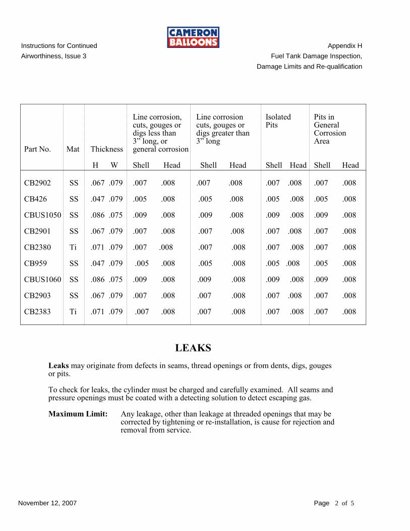
Line corrosion, Line corrosion Isolated Pits in cuts, gouges or cuts, gouges or Pits General digs less than digs greater than Corrosion 3” long, or 3” long Area Part No. Mat Thickness general corrosion H W Shell Head Shell Head Shell Head Shell Head
CB2902 SS .067 .079 .007 .008 .007 .008 .007 .008 .007 .008 CB426 SS .047 .079 .005 .008 .005 .008 .005 .008 .005 .008 CBUS1050 SS .086 .075 .009 .008 .009 .008 .009 .008 .009 .008 CB2901 SS .067 .079 .007 .008 .007 .008 .007 .008 .007 .008 CB2380 Ti .071 .079 .007 .008 .007 .008 .007 .008 .007 .008 CB959 SS .047 .079 .005 .008 .005 .008 .005 .008 .005 .008 CBUS1060 SS .086 .075 .009 .008 .009 .008 .009 .008 .009 .008 CB2903 SS .067 .079 .007 .008 .007 .008 .007 .008 .007 .008 CB2383 Ti .071 .079 .007 .008 .007 .008 .007 .008 .007 .008
LEAKS Leaks may originate from defects in seams, thread openings or from dents, digs, gouges or pits. To check for leaks, the cylinder must be charged and carefully examined. All seams and pressure openings must be coated with a detecting solution to detect escaping gas. Maximum Limit: Any leakage, other than leakage at threaded openings that may be
corrected by tightening or re-installation, is cause for rejection and removal from service.
Instructions for Continued Appendix H
Airworthiness, Issue 3 Fuel Tank Damage Inspection,
Damage Limits and Re-qualification
November 12, 2007 Page 3 of 5
BULGES Maximum Limit: Cylinders which have definite visual bulges shall be rejected and
removed from service.
FIRE DAMAGE Maximum Limit: Cylinders which have been damaged by fire shall re rejected and
removed from service.
GENERAL DISTORTION Damage Limit: If any cylinder valve is noticeably tilted, the cylinder shall be
rejected and removed from service.
FOOT RINGS AND HEAD RINGS Foot rings and head rings should be examined to determine that they are in serviceable condition. Damage Limit: Any damage to the foot ring that prevents the cylinder from free
standing shall result in the cylinder being rejected and removed from service.
Any damage to the head ring which would prevent the protection
of the cylinder valves shall result in the cylinder being rejected and removed from service.
INSPECTION REPORT FORM The Department of Transportation Regulations require that results of the Re-qualification inspection be recorded and a permanent record be kept of all Visual Re-qualification Inspections. All required information is included on the supplied form. See Appendix H page 4
STAMPING VISUALLY RE-QUALIFIED CYLINDERS
A cylinder which passes a visual inspection must have the RIN and the new certification date stamped on the cylinder. The RIN is stamped above, below or before the date of inspection. The complete visual inspection is designated by stamping the letter “E” following the re-qualification date, i.e. ‘1107E’. This means the cylinder was Visually Re-qualified in November of 2007. The stamping must be placed adjacent to the previous date. It is recommended that the numbering die stamp used be from 3/16” to 1/4”.
Instructions for Continued Appendix H
Airworthiness, Issue 3 Fuel Tank Damage Inspection,
Damage Limits and Re-qualification
November 12, 2007 Page 4 of 5
RM
= R
em
ove fro
m S
erv
ice
SC
= S
cra
p
OK
= R
etu
rn to
serv
ice
Dis
po
sitio
n C
od
es
Instructions for Continued Appendix H
Airworthiness, Issue 3 Fuel Tank Damage Inspection,
Damage Limits and Re-qualification
November 12, 2007 Page 5 of 5
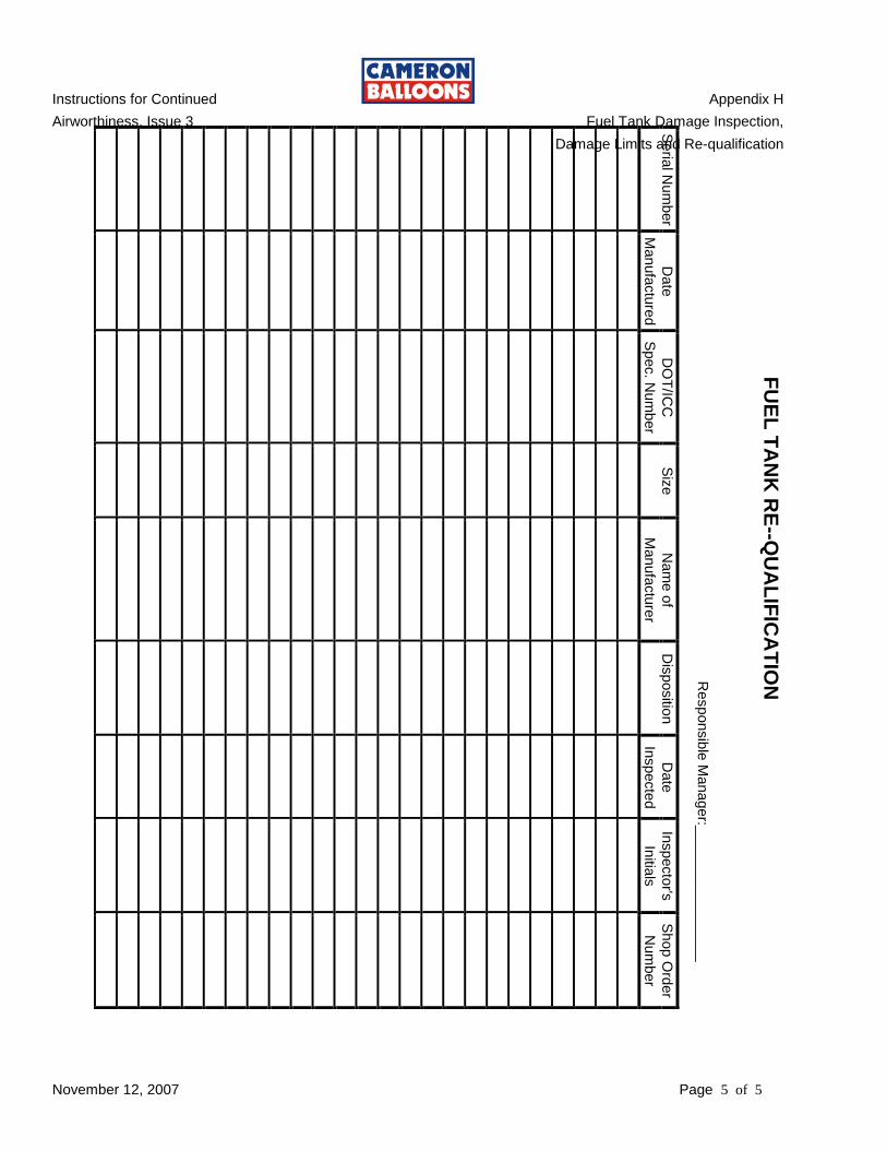
Seria
l Num
ber
Manufa
ctu
red
Date
Spec. N
um
ber
DO
T/IC
C
S
ize
Manufa
ctu
rer
Nam
e o
f
Dis
positio
n
Inspecte
d
Date
Initia
ls
Inspecto
r's
Num
ber
Shop O
rder
Responsib
le M
anager:_
________________
FU
EL
TA
NK
RE
--QU
AL
IFIC
AT
ION
Instructions for Continued Appendix I
Airworthiness, Issue 3 Kevron Vertical Load Tapes
January 01, 2009 Page 1 of 6
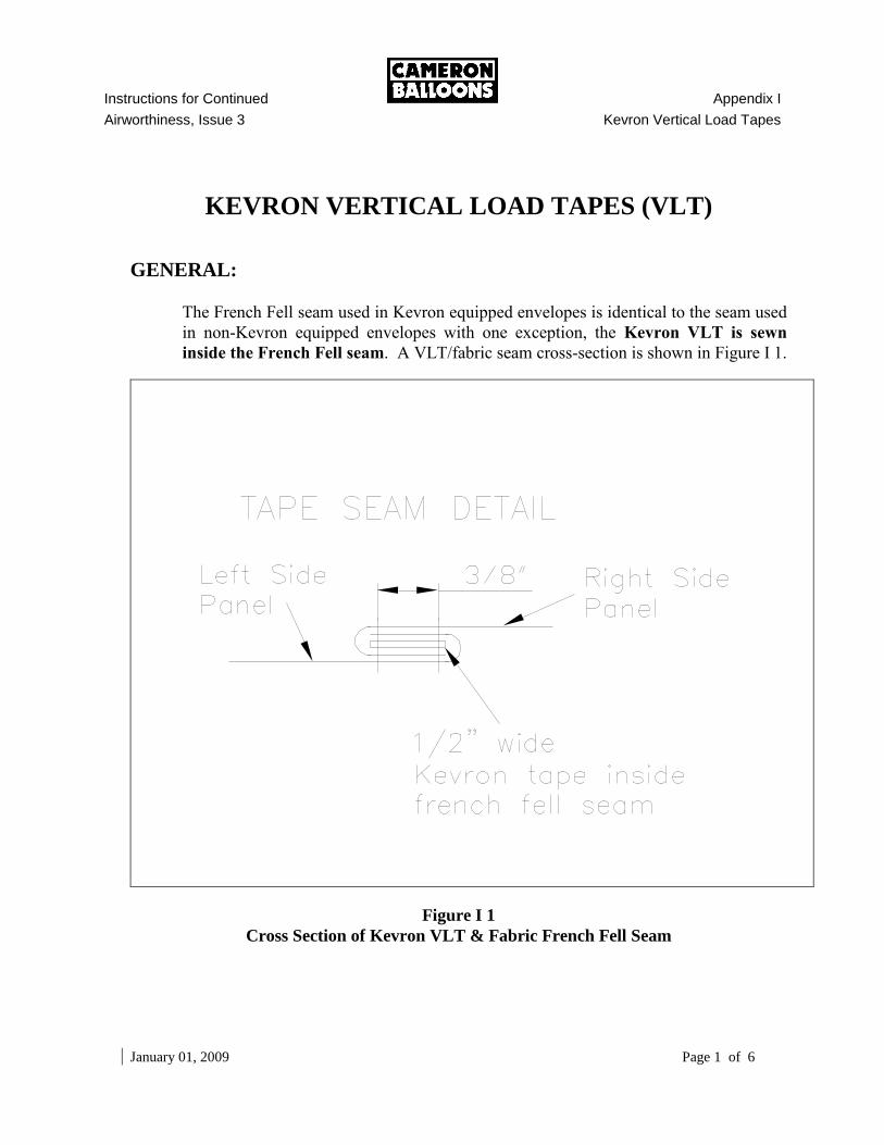
KEVRON VERTICAL LOAD TAPES (VLT)
GENERAL:
The French Fell seam used in Kevron equipped envelopes is identical to the seam used
in non-Kevron equipped envelopes with one exception, the Kevron VLT is sewn
inside the French Fell seam. A VLT/fabric seam cross-section is shown in Figure I 1.
Figure I 1
Cross Section of Kevron VLT & Fabric French Fell Seam
Instructions for Continued Appendix I
Airworthiness, Issue 3 Kevron Vertical Load Tape
January 01, 2009 Page 2 of 6
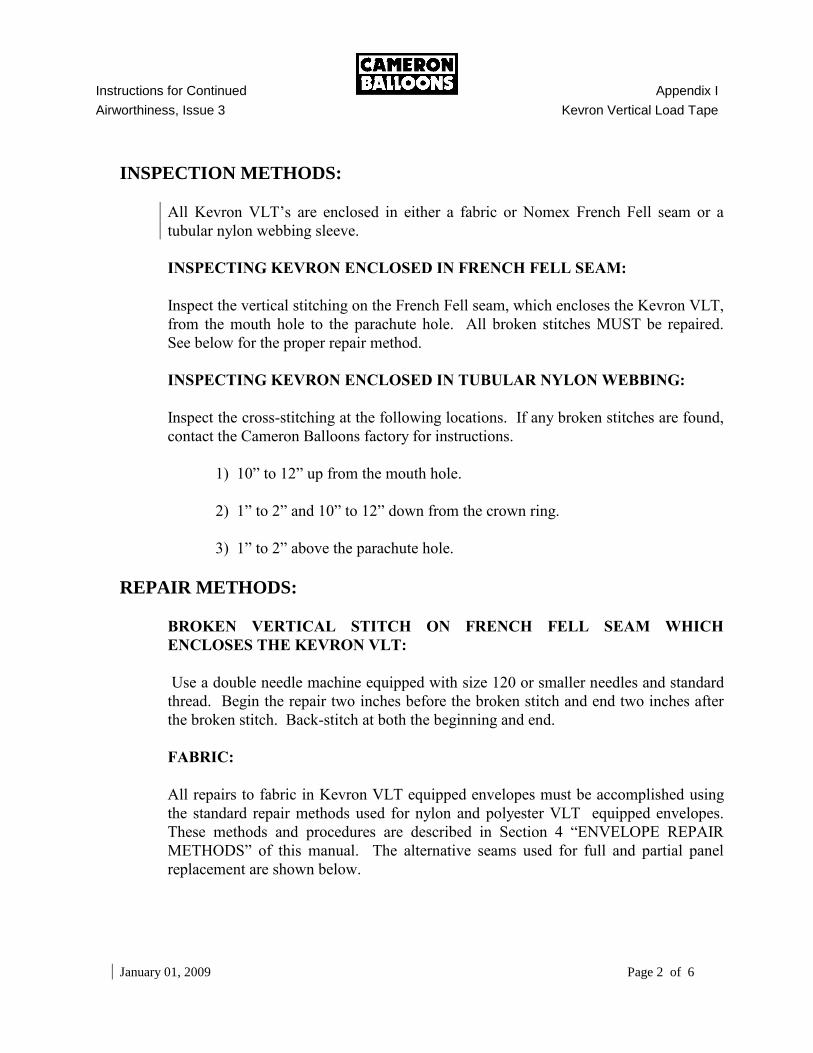
INSPECTION METHODS:
All Kevron VLT’s are enclosed in either a fabric or Nomex French Fell seam or a
tubular nylon webbing sleeve.
INSPECTING KEVRON ENCLOSED IN FRENCH FELL SEAM:
Inspect the vertical stitching on the French Fell seam, which encloses the Kevron VLT,
from the mouth hole to the parachute hole. All broken stitches MUST be repaired.
See below for the proper repair method.
INSPECTING KEVRON ENCLOSED IN TUBULAR NYLON WEBBING:
Inspect the cross-stitching at the following locations. If any broken stitches are found,
contact the Cameron Balloons factory for instructions.
1) 10” to 12” up from the mouth hole.
2) 1” to 2” and 10” to 12” down from the crown ring.
3) 1” to 2” above the parachute hole.
REPAIR METHODS:
BROKEN VERTICAL STITCH ON FRENCH FELL SEAM WHICH
ENCLOSES THE KEVRON VLT:
Use a double needle machine equipped with size 120 or smaller needles and standard
thread. Begin the repair two inches before the broken stitch and end two inches after
the broken stitch. Back-stitch at both the beginning and end.
FABRIC:
All repairs to fabric in Kevron VLT equipped envelopes must be accomplished using
the standard repair methods used for nylon and polyester VLT equipped envelopes.
These methods and procedures are described in Section 4 “ENVELOPE REPAIR
METHODS” of this manual. The alternative seams used for full and partial panel
replacement are shown below.
Instructions for Continued Appendix I
Airworthiness, Issue 3 Kevron Vertical Load Tapes
January 01, 2009 Page 3 of 6
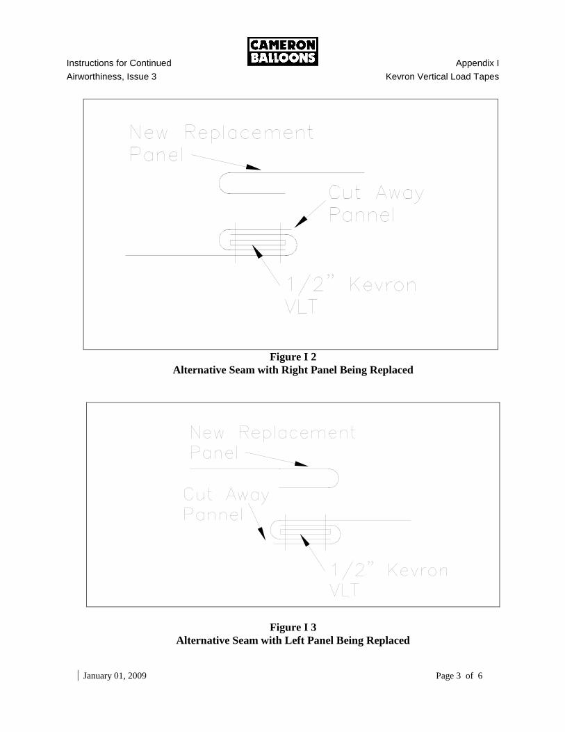
Figure I 2
Alternative Seam with Right Panel Being Replaced
Figure I 3
Alternative Seam with Left Panel Being Replaced
Instructions for Continued Appendix I
Airworthiness, Issue 3 Kevron Vertical Load Tape
January 01, 2009 Page 4 of 6
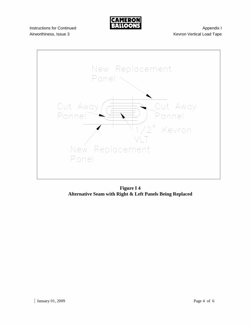
Figure I 4
Alternative Seam with Right & Left Panels Being Replaced
Instructions for Continued Appendix I
Airworthiness, Issue 3 Kevron Vertical Load Tapes
January 01, 2009 Page 5 of 6
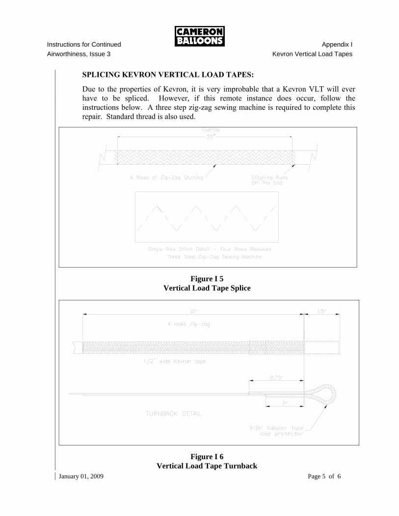
SPLICING KEVRON VERTICAL LOAD TAPES:
Due to the properties of Kevron, it is very improbable that a Kevron VLT will ever
have to be spliced. However, if this remote instance does occur, follow the
instructions below. A three step zig-zag sewing machine is required to complete this
repair. Standard thread is also used.
Figure I 5
Vertical Load Tape Splice
Figure I 6
Vertical Load Tape Turnback
Instructions for Continued Appendix I
Airworthiness, Issue 3 Kevron Vertical Load Tape
January 01, 2009 Page 6 of 6
ALLOWABLE DAMAGE:
No broken stitches in the vertical stitching on the French Fell seam, which encloses the
Kevron VLT, from the mouth hole to the parachute hole, are permitted.
No broken stitches in the cross-stitching listed above is permitted.
Consult Cameron Balloons if questions arise on the airworthiness or legality of a
repair, installation or damage.
Instructions for Continued Appendix J
Airworthiness, Issue 3 Open Baskets with Top Frame and Solid Floor
November 12, 2007 Page 1 of 12
APPENDIX J
OPEN BASKETS WITH TOP FRAME AND SOLID FLOOR
J.1 GENERAL DESCRIPTION
Cameron Balloons US offers open (no inside partitions) baskets, which incorporate a rigid top frame and either a woven floor or a solid floor. These baskets incorporate the FlexiRigidTM burner support system. In the logbook, flight manual and on the basket identification plate, the part number includes all the information needed to identify the basket. For example, 301-6FSHA. (301) indicates the Aristocrat series. (–6) indicates the basket size, in this case –6 is a 46x62 basket, we also offer (-7) for 42x50 and (-3) for 42x52 and (-4) for 42x58 basket and (–5) for 48x72 basket. (F) indicates a flat top. (S) indicates a solid floor, we also offer (W) for woven floor. (H) indicates a hi-spec, which means the hi spec basket may carry 15 or 20 gallon fuel tanks, we also offer (S) spec which means the standard spec basket may only carry 15 gallon fuel tanks. The (A) indicates the Drawing Revision. For all repairs below the top frame on woven floor baskets refer to Section 7 “BASKET AND SUSPENSION SYSTEM” in the main manual.
J.2 BASKET SKIDS – SOLID FLOOR BASKET
Skids are made of Maple, Red Oak or Ash. Maple is the current production standard and the preferred repair/replacement skid material. Pre-drilled and custom fit skids are available from Cameron Balloons US for every basket. The three approved woods may be used interchangeably and are easily purchased from local suppliers. A strip of nylon or UHMW plastic of 1/2” maximum thickness may be added to the bottom edge of each skid. Stainless steel screws inserted in countersunk holes are recommended for installation. A broken skid must be replaced unless the break is outside the outermost bolt. If the break is at or inside the outermost bolt, the skid must be replaced. Refer to Section J.11, “Allowable Damage” for additional damage limits. The skid can be removed by undoing the retaining bolts. This can only be done from underneath the basket. The skids are glued on as well, so excessive force could cause de-lamination of the plywood floor. Work carefully and from one end. Install skids with new hardware and use a good waterproof wood adhesive. The removed skid could be used as a pattern for its replacement, including the angle of cut at the ends and the location of the bolt holes. Replacement skids are best acquired from Cameron Balloons US and can normally be shipped the same day as ordered. Have ready the basket part number when ordering a replacement skid. Acquiring the skid material locally and fabricating the skids in the field will generally be more expensive and of lower quality than if acquired from Cameron Balloons.
Instructions for Continued Appendix J
Airworthiness, Issue 3 Open Baskets with Top Frame and Solid Floor
November 12, 2007 Page 2 of 12
J.3 SOLID FLOOR
Cracks in solid floors that are visible on both sides of the wood and are between
3” and 18” in length should be repaired by fitting a marine plywood patch to the
inside of the basket floor. The patch must be of at least the same thickness as the
floor and must be screwed and bonded in place. If the crack is greater than 18”
the floor must be replaced.
If the anti-slip strips are worn out or damaged they should be replaced.
J.4 BOTTOM SCUFF TRIM & CABLE PROTECTION–SOLID FLOOR
BASKETS
The bottom edge of the solid floor basket is fitted with rawhide. The purpose of the rawhide is to protect the bottom floor lacing and attachment pieces. The position of the rawhide should provide as much coverage and protection to the bottom edge as possible. Scuff rawhide is 7 inch wide limed Water Buffalo rawhide. The rawhide should be soaked for several hours. The top of the scuff rawhide is attached to the basket by a lacing method. The current method uses 1/8" polyester line, dyed to match the rawhide color, to attach the side pieces. The Solid Floor basket skuff rawhide sides are laced directly to each other with 3-4 inch overlap using rawhide lace. The rawhide is NOT pre-punched. Punching must be done one hole at a time as the rawhide is installed. This method is used to align the holes with the spaces between rattan uprights in the basket. The rawhide should be installed along the top edge first.
A) SCUFF RAWHIDE TOP EDGE LACING:
Begin just under the lowest layer of colored weave. Punch the lacing holes in the rawhide about 3/8" from the outer edge. The 3/8" at the edge of the rawhide will prevent the lacing from tearing out after the rawhide has dried. The 3/8" will also enable you to tuck the edge of the rawhide into the weave (use a tool such as a dull screwdriver).
1) Tie one end of the polyester lace around an upright or horizontal
tri-weave.
Instructions for Continued Appendix J
Airworthiness, Issue 3 Open Baskets with Top Frame and Solid Floor
November 12, 2007 Page 3 of 12
2) Place the rawhide piece on the basket. Support both ends of the
rawhide piece.
3) Punch the first hole directly above the tie off.
4) Insert the lace through the hole from the back side of the rawhide,
up and through the space between the two uprights directly above
the hole and into the basket. The lace must pass between the dyed
weave row and highest tri-weave row.
5) Guide the lace around the inner side of the upright and pull the lace
through the adjacent upright space. The lace must pass between
the dyed weave row and highest tri-weave row.
6) Punch the next hole half way between the next two adjacent
uprights. Insert the lace through the hole from the back side of the
rawhide, up and through the space between the two uprights
directly above the hole and into the basket. The lace must pass
between the dyed weave row and highest tri-weave row. Pull the
lace tight. Tuck the rawhide edge between the rows of weave.
7) Repeat steps (4) through (6) until the side top is complete.
8) This method is suitable for the basket end top as well.
B) SCUFF RAWHIDE BOTTOM EDGE ATTACHMENT:
Pull the rawhide down as far as it will go, usually about 3 inches onto the floor of the basket, but leave it loose as it will shrink tight when it dries. Use double rows of 1/2" staples closely spaced to staple the rawhide to the basket floor.
C) RAWHIDE CABLE PROTECTION:
The cable protection rawhide is 4 1/2 inches wide. Center the rawhide strip over the basket suspension cable. Use double rows of 1/2" staples closely spaced to staple all exterior edges of the rawhide to the basket floor. Next, while keeping the cable centered in the rawhide, use double rows of 1/2" staples to staple on both sides of the cable.
Instructions for Continued Appendix J
Airworthiness, Issue 3 Open Baskets with Top Frame and Solid Floor
November 12, 2007 Page 4 of 12
J.5 VERTICAL WICKER (“UPRIGHTS”) REPAIR
There are two types of vertical uprights, the standard uprights and the reinforcing uprights. Broken reinforcing vertical uprights must be replaced before further operation. If a reinforcing upright which forms the step hole or which the tank belts bear is broken at any point, the upright must be replaced. Broken standard vertical uprights must be repaired at the next Annual/100 hour inspection, however, broken standard uprights directly below the step hole must be repaired before further operation. Broken standard vertical uprights may be repaired and reinforced with 3/8" nylon rod. The rod should extend six inches above and below the damaged area. If a standard upright that is directly adjacent to a belt hole is broken, it must be repaired before further operation.
A) REPAIR STANDARD UPRIGHTS WITH NYLON ROD:
1) Sharpen the rod slightly on one end to ease installation.
2) Spray the rod and the repair area with silicone lubricant.
3) Insert the rod 6 inches or more above the damaged area and drive
the rod along the broken vertical member until it reaches the
desired location and both ends are inside the weave.
If an excessive amount of standard vertical uprights are damaged (Refer to Section J.11, “ALLOWABLE DAMAGE”) or the damage is done in such a way that reinforcement with nylon rod is not acceptable the vertical uprights must be removed and replaced.
B) REPAIR BY REPLACEMENT:
1) Remove the top bolster in the area above the damaged uprights.
2) Remove the stainless steel BanditTM clamps as necessary.
3) Remove the top frame is necessary.
4) Remove the rawhide scuff leather as necessary.
Instructions for Continued Appendix J
Airworthiness, Issue 3 Open Baskets with Top Frame and Solid Floor
November 12, 2007 Page 5 of 12
5) Remove enough of the tri-weave to gain access to the broken
upright and bottom frame.
6) Pull the vertical uprights out with a vise grip type tool and
hammer. This method is aided by the use of silicon spray
lubricant.
7) Drive a new piece of the correct size rattan into place until it
bottoms out against the bottom frame, this method is aided by the
use of silicone spray.
8) Install a 4” long 3/4" wide piece of rawhide between the bottom
frame and the basket floor with equal lengths on each side of the
bottom frame. Staple the rawhide to the uprights on the inside and
outside of the basket
9) Replace the tri-weave.
10) Replace the rawhide scuff leather
11) Replace the top frame if it was removed.
11) Install NEW BanditTM
clamps or Cameron supplied heavy-duty
wire ties. The BanditTM
installation tool is available for loan from
Cameron Balloons U.S.
12) Replace the top bolster.
J.6 HORIZONTAL WEAVE REPAIR
Sections of horizontal weave may be replaced with rattan of a similar size. Cameron Balloons US baskets are made primarily of a "natural" rattan (i.e. one that does not have its natural outer skin removed). Small quantities of stripped rattan ("round reed") are used for accenting stripes. The stripped rattan is easily dyed using common Rit
TM dye. The stripped rattan is more brittle and is not as
strong as the natural rattan (with natural cover) and should not replace the natural rattan in repair work. When replacing horizontal weave it is important that the new woven piece be at least 12" long. Pieces shorter than 12" will not span enough vertical members to remain properly positioned in use.
Instructions for Continued Appendix J
Airworthiness, Issue 3 Open Baskets with Top Frame and Solid Floor
November 12, 2007 Page 6 of 12
In the Aristocrat style basket the ends of horizontal weave may be turned down as is standard or overlapped in-between two vertical uprights as on a Sport Basket.
J.7 TOP BOLSTER PATCHING
Repairs may be made to the top bolster (suede, smooth leather or cordura) by cementing a patch with contact cement on the underside of the damaged area (Goodyear's PliobondTM contact cement works especially well for this). In the case of a tear it should be possible to bring the edges together. The reinforcement piece placed under the bolster material should extend at least 1/2" beyond the damaged area in all directions. Suede may be rejuvenated with the use of commercially available suede brushes and suede stones. It is our experience that dry cleaning solvents and soaps should be avoided as they remove the oil in the suede, discoloring and hardening it. Shoe polish, mink and neat's-foot oil type treatments work well on smooth leather. Cordura can be washed with a mild soap solution, rinsed with clear, hot water and allowed to dry before covering.
J.8 REPLACEMENT OF BASKET CABLES
The stainless steel cable woven through the basket may be spliced or replaced. Replacement is the preferred repair.
CAUTION:
Before starting this process, contact Cameron Balloons US for information on swaging. The necessary tools MUST be borrowed from Cameron Balloons US on a loan basis and the proper parts purchased.
A) CABLE REPLACEMENT:
1) Remove the center skid.
2) Remove the pressed on ferrule from the cable, which is
located under the center skid. This can be accomplished by
cutting the cable on both sides of the ferrule.
3) Slide a new Nicopress ferrule onto the new cable. Secure
the ferrule at the mid-way point of the cable with tape.
4) Butt weld an appropriate length of new 6mm stainless steel
cable to the ends of the cable where the ferrule was
removed.
Instructions for Continued Appendix J
Airworthiness, Issue 3 Open Baskets with Top Frame and Solid Floor
November 12, 2007 Page 7 of 12
5) Place heavy weight (sand bags etc.) inside the basket near
the corner where the cable will first be pulled from.
6) Pull one side of the old cable with an overhead hoist or
block and tackle until the mid-point of the new cable is in
the center of the basket floor. Silicone spay lubricant will
help in this step.
7) Repeat number 5 and six for the other half of the cable.
8) Swage the Nicopress ferrule at a position where it will fit in
the notch in the center skid.
9) Install the skid using new hardware.
10) Install new vinyl cable covering.
11) Cut, thimble and swage the cables to the correct length.
J.9 ROPE AT TOP AND BOTTOM OF BASKET
The rope used for the internal passenger handholds and external carrying handles is a 3/4" polypropylene which, for aesthetic reasons, has been colored and finished to have the appearance of natural Manila rope. The woven rope handles are constructed with three individual strands twisted together. The area between handles is comprised of two strands. The two strand weave runs completely around the basket and only in the actual handle is the third strand incorporated.
A) SPLICING THE TWO STRAND WEAVE:
1) Separate the coiled three strands into three separate pieces.
2) Start at least two vertical uprights from the nearest handle, farther
away from the break if possible. Allow six inches of extra rope at
the start of the splice (this will later be fused to the existing rope).
3) Use two strands to reconstruct the existing pattern of rope weave.
This is best done with two people, one inside and one outside the
basket, to facilitate feeding the rope back and forth into and out of
the basket between the uprights and through the weave.
Instructions for Continued Appendix J
Airworthiness, Issue 3 Open Baskets with Top Frame and Solid Floor
November 12, 2007 Page 8 of 12
J.10 FORMING A HANDLE
A handle is formed by introducing the third strand of rope at the point where the handle extends from the basket wall.
A) FORMING A ROPE HANDLE:
1) Begin with the two rope weave on the inside of the basket so the
melted splice is not visible from the outside. It is also preferable to
start the weave behind a tank location.
2) The two strand weave rope will be joined by the third independent
strand to form the handle. The two strands of the two strand rope
weave exit the basket interior and are separated by the handle-edge
upright.
3) The third strand is now introduced. Begin at a point approximately
six inches from the end of the independent third rope strand.
4) Twist the independent third strand into the first two strands until
the length needed for the handle is attained (in production this is 15
twists of three strand).
5) One of the original two strands enters the basket interior through
the space between the second and third upright from the original
handle starting point, while the second rope strand remains on the
exterior..
6) The third rope strand should have a tail about six inches long
remaining and "sticking up" after one of the original two rope
strands have re-entered the basket. The two original rope strands
will continue around the basket.
7) The two 6 inch end pieces of the third rope strand can now be
woven in and out of the uprights between the new handle ends to
fill that area.
Instructions for Continued Appendix J
Airworthiness, Issue 3 Open Baskets with Top Frame and Solid Floor
November 12, 2007 Page 9 of 12
a) Stretch loosely the 6 inch piece of the third rope strand
protruding from the handle starting point upright, along the
inside of the basket to the handle ending point upright.
Twist the rope handle at the ending point in such a fashion
as to loosen the rope around the upright. Insert the
remainder of the 6 inch piece of the third strand down and
through the hole made from twisting the handle and
adjacent to the upright.
b) Guide the 6 inch piece of the third rope strand protruding
from the ending point upright between the ending point
upright and its inner adjacent handle upright, on top of,
behind and under the other third strand of rope. Apply a
gentle sawing motion to center the intersection between the
two uprights. Use care to prevent the rope from untwisting
while cinching up the two strands.
c) Repeat step (b) for the two remaining gaps between the
handle end points.
d) Twist the rope handle at original beginning point in such a
fashion as to loosen the rope around the upright. Insert the
remainder of the 6 inch piece of the third strand down and
through the hole made from twisting the handle and
adjacent to the upright.
The difference between original handle construction and repair construction is the manner in which the third strand ends are tucked into the basket. The third strand ends of the original handle ends are guided up and taped to the wicker uprights at the ends of the handles. For repairs, the ends are tucked into the adjacent two-strand weave and the ends are melted into place to prevent dislocation or fraying.
J.11 ALLOWABLE DAMAGE
GENERAL: The following specific conditions do NOT make the balloon un-airworthy. Although operation of the balloon is allowed, it is best to repair these conditions at the earliest convenient opportunity, preferably no later than the time of the next Annual/100-hour inspection. Consult Cameron Balloons if questions arise on the airworthiness or legality of a repair, installation or equipment damage.
Instructions for Continued Appendix J
Airworthiness, Issue 3 Open Baskets with Top Frame and Solid Floor
November 12, 2007 Page 8 of 12
A) SKIDS:
A single basket skid may be cracked: (1) if all parts of the crack are within 1/2" from an outside surface or (2) if the crack does not extend lengthwise from the end of the skid to one of the endmost skid bolts.
B) BOTTOM SCUFF RAWHIDE:
Any damage to the scuff rawhide that exposes the edge of the solid floor, the basket lower frame, the 6mm stainless steel cable or the polyester lacing that is used to lash the floor and lower frame together is NOT PERMITTED. This damage MUST be repaired before further operation. Any other damage to the scuff rawhide MUST be repaired at the next annual/100 hour inspection.
C) CABLE PROTECTING RAWHIDE: Cable protecting rawhide is stapled over the 6mm stainless steel cable on the outside basket floor. Any damage to the cable protecting rawhide that exposes the 6mm stainless steel cable MUST be repaired before further operation.
D) SOLID FLOOR
Any crack that is visible from either side of the floor (not both sides).
Any crack that is less than 3” in length
E) TOP BOLSTER:
Top bolster damage is permitted as long as the protective closed cell foam on the basket top edge remains firmly held in place.
F) UPRIGHTS:
One or two contiguous standard uprights may be broken, provided the next three uprights on both sides are not broken.
G) HORIZONTAL WEAVE:
Broken horizontal weave which does not permit an object larger than 3/4 inch in diameter to pass through the broken section is permitted.
Instructions for Continued Appendix J
Airworthiness, Issue 3 Open Baskets with Top Frame and Solid Floor
November 12, 2007 Page 11 of 12
H) BASKET SUSPENSION CABLES:
Basket suspension cables are made up of 6mm stainless steel 6x19 wire. Up to 38 total individual wire strands may be broken in the thimble area (beyond the ferrule) on any single suspension cable. Up to 19 total individual wire strands may be broken on one single basket suspension cable in any location other than the thimble area. Damaged wire strands in the thimble area should be trimmed of any sharp protruding ends and the area covered with an epoxy cement to protect against the danger of snagging persons or other parts of the balloon. Damaged wire strands in other areas of the cable should be covered with heat shrink tubing or several layers of electrical tape to afford the same protection.
I) SUSPENSION CABLE PLASTIC TUBING COVER:
Un-repaired damage is not permitted. If damaged, the damaged section of the protective vinyl basket cable covering must be wrapped with at least 1/16" thickness of electrical tape or heat shrink tubing, to at least 1" beyond the damaged area in each direction.
J) TOP & BOTTOM FRAMES:
Slight to moderate bends are permitted to the top frame & bottom frame as long as all bends are smooth and there are no cracks, creases or kinks present.

Instructions for Continued Appendix J
Airworthiness, Issue 3 Open Baskets with Top Frame and Solid Floor
November 12, 2007 Page 12 of 12
THIS PAGE INTENTIONALLY BLANK
Instructions for Continued Appendix K
Airworthiness, Issue 3 Envelope Velcro Tabs Installation
January 01, 2004 Page 1 of 4
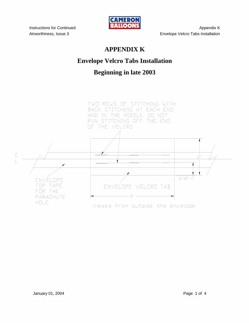
APPENDIX K
Envelope Velcro Tabs Installation
Beginning in late 2003
Instructions for Continued Appendix K
Airworthiness, Issue 3 Envelope Velcro Tabs Installation
January 01, 2004 Page 2 of 4
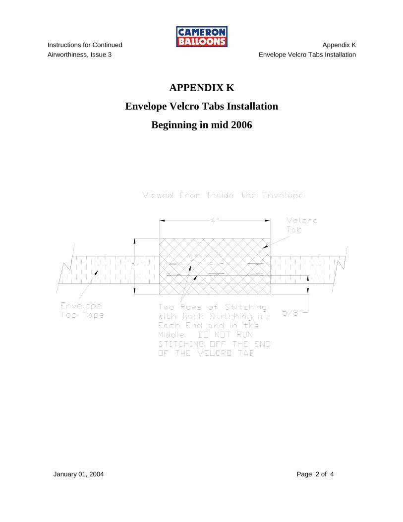
APPENDIX K
Envelope Velcro Tabs Installation
Beginning in mid 2006
Instructions for Continued Appendix K
Airworthiness, Issue 3 Envelope Velcro Tabs Installation
November 12, 2007 Page 3 of 4
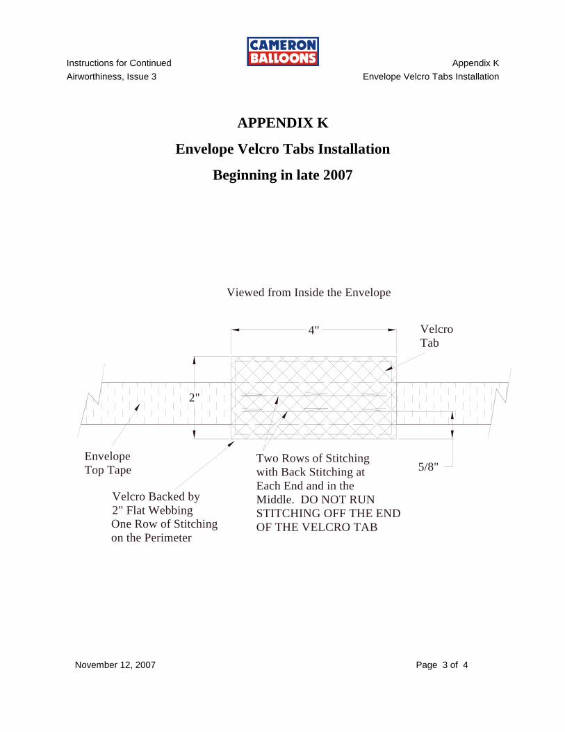
APPENDIX K
Envelope Velcro Tabs Installation
Beginning in late 2007
2"
4"
Envelope
Top Tape
Velcro
Tab
Two Rows of Stitching
with Back Stitching at
Each End and in the
Middle. DO NOT RUN
STITCHING OFF THE END
OF THE VELCRO TAB
Viewed from Inside the Envelope
5/8"
Velcro Backed by
2" Flat Webbing
One Row of Stitching
on the Perimeter

Instructions for Continued Appendix K
Airworthiness, Issue 3 Envelope Velcro Tabs Installation
November 12, 2007 Page 4 of 4
THIS PAGE INTENTIONALLY BLANK
Instructions for Continued Appendix L
Airworthiness, Issue 3 Ball 655 & M55 Wires
January 01, 2004 Page L 1
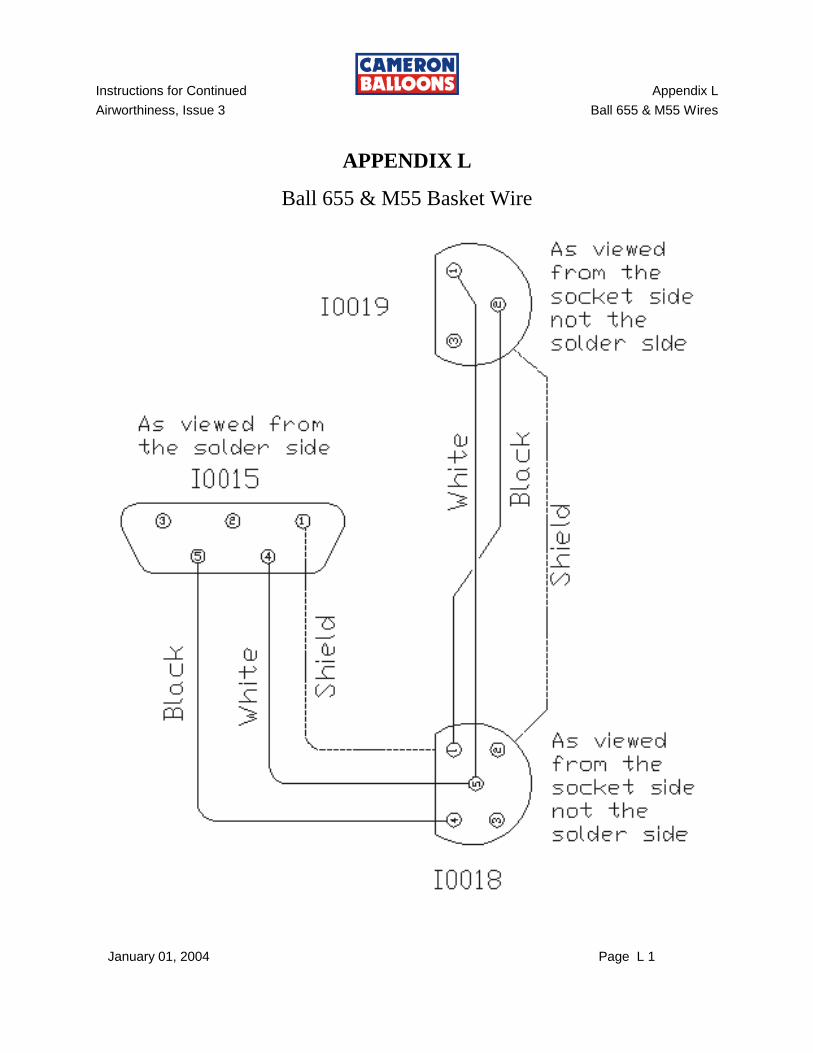
APPENDIX L
Ball 655 & M55 Basket Wire
Instructions for Continued Appendix L
Airworthiness, Issue 3 Ball 655 & M55 Wires
January 01, 2004 Page L 2
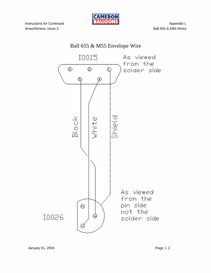
Ball 655 & M55 Envelope Wire
Instructions for Continued Appendix L
Airworthiness, Issue 3 Ball 655 & M55 Wires
January 01, 2004 Page L 3
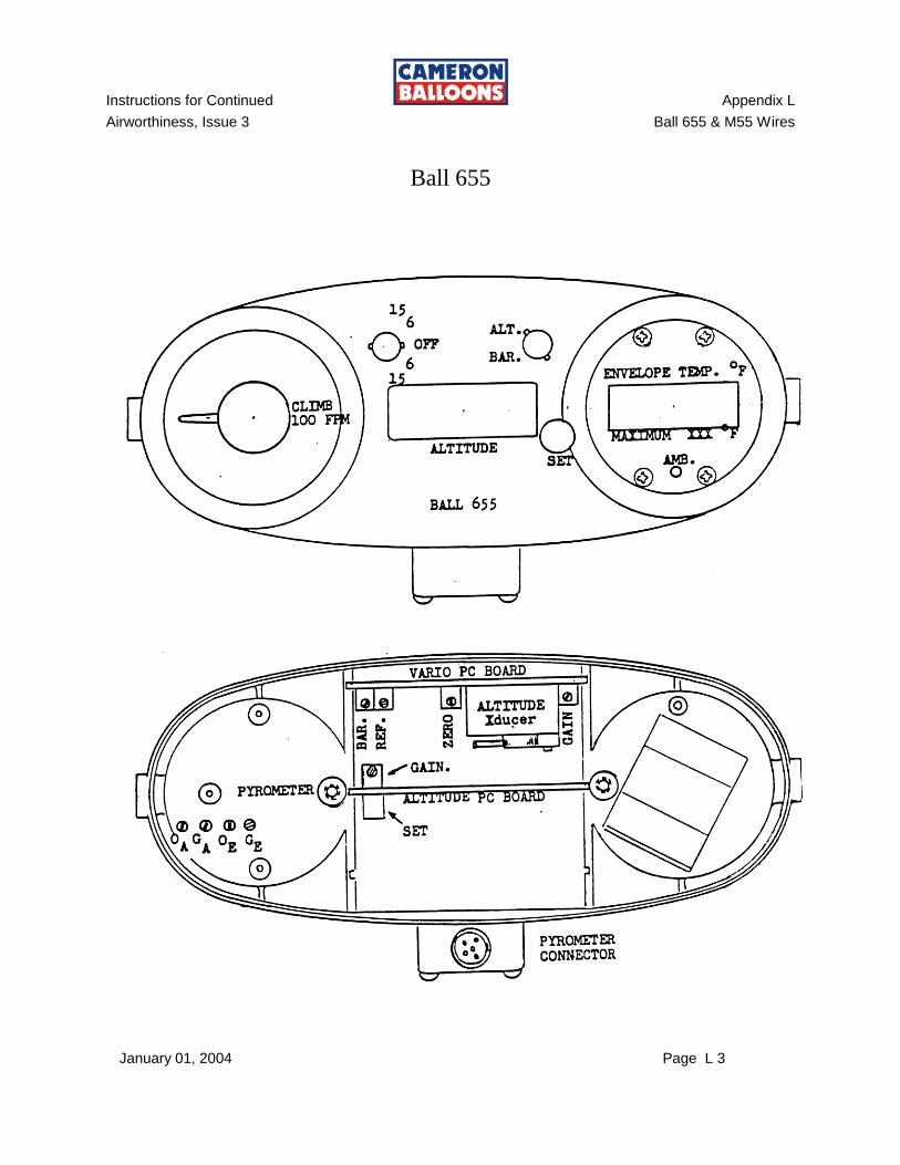
Ball 655

Instructions for Continued Appendix L
Airworthiness, Issue 3 Ball 655 & M55 Wires
January 01, 2004 Page L 4
THIS PAGE INTENTIONALLY BLANK
Instructions for Continued Appendix M
Airworthiness, Issue 3 Inspection Checklist References
November 12, 2007 Page M1 of M2
INSPECTION CHECK LIST REFERENCES
The Inspection Check List references specific procedures. These include:
Item "I. A-E", Fabric Strength. Refer to Section 4.30
Item "IV. A", Valve Centering Lines Length. Refer to Section 4.29
Item "IV. E", Parachute Red Line Length. Refer to Section 4.21
Item “V. D”, Easy Vent Round Red Line Length. Refer to Section 4.21
Item “V. E”, Easy Vent Flat Red Line Length. Refer to Section 4.22
Item “VI A”, Rip Panel Perimeter Velcro. Call Cameron Balloons US
Item “VII H”, Regulator, Dissemble & Clean, MK IV Ultra. Refer to Section 6.25
Item “VII H”, Regulator, Dissemble & Clean, Sirocco. Refer to Appendix G Section G
Item “VII J”, Blast Valve, Dissemble & Clean, MK & MK IV Std. Refer to Section 6.17
Item “VII J”, Blast Valve, Dissemble & Clean, MK IV Super. Refer to Section 6.18
Item “VII J”, Blast Valve, Dissemble & Clean, MK IV Ultra. Refer to Section 6.19
Item “VII J”, Blast Valve, Dissemble & Clean, Sirocco. Refer to Appendix G Section E
Item “VII M”, Whisper Valve Lubrication. Refer to Section 6.9 B
Item "VIII. A." Temperature Calibration Procedure. Ball 655. Refer to Section 8.1
Item "X. A A&B." Fuel Tank Dip Tube. Refer to Section 6.31 B
Item "X. A R." Fuel Tank Re-qualification. Refer to Section 6.31 D & Appendix H

Instructions for Continued Appendix M
Airworthiness, Issue 3 Inspection Checklist References
November 12, 2007 Page M2 of M2
THIS PAGE INTENTIONALLY BLANK
Instructions for Continued Appendix N
Airworthiness, Issue 3 24 Valve Centering Line Parachute Adjustment
January 01, 2009 Page N 1
APPENDIX N
24 VALVE CENTERING LINE PARACHUTE ADJUSTMENT
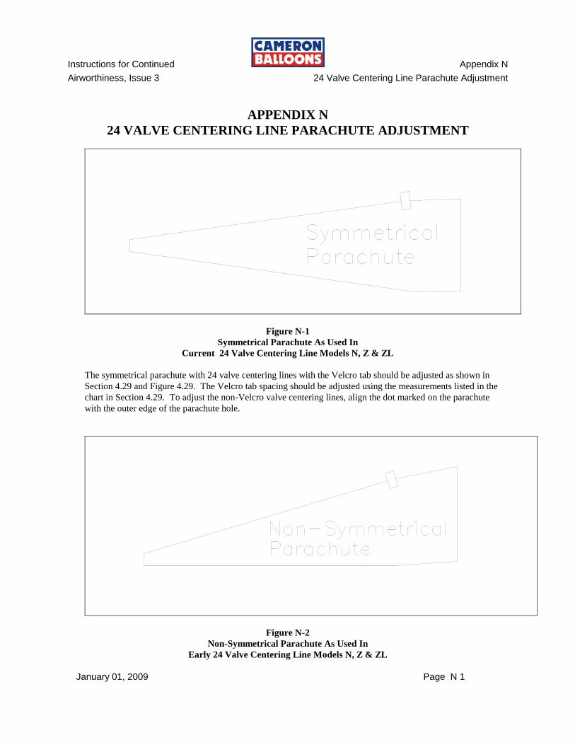
Figure N-1
Symmetrical Parachute As Used In
Current 24 Valve Centering Line Models N, Z & ZL
The symmetrical parachute with 24 valve centering lines with the Velcro tab should be adjusted as shown in
Section 4.29 and Figure 4.29. The Velcro tab spacing should be adjusted using the measurements listed in the
chart in Section 4.29. To adjust the non-Velcro valve centering lines, align the dot marked on the parachute
with the outer edge of the parachute hole.
Figure N-2
Non-Symmetrical Parachute As Used In
Early 24 Valve Centering Line Models N, Z & ZL
Instructions for Continued Appendix N
Airworthiness, Issue 3 24 Valve Centering Line Adjustment
January 01, 2009 Page N 2
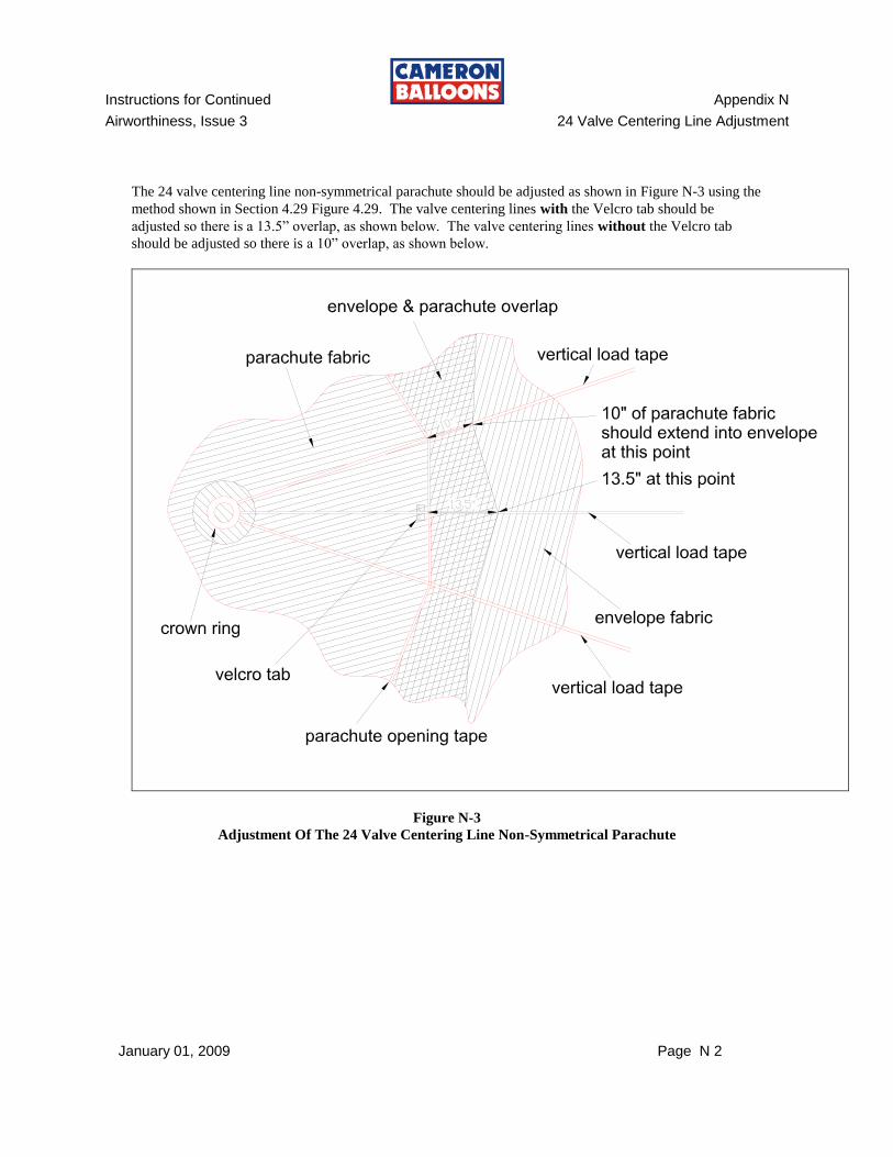
The 24 valve centering line non-symmetrical parachute should be adjusted as shown in Figure N-3 using the
method shown in Section 4.29 Figure 4.29. The valve centering lines with the Velcro tab should be
adjusted so there is a 13.5” overlap, as shown below. The valve centering lines without the Velcro tab
should be adjusted so there is a 10” overlap, as shown below.
Figure N-3
Adjustment Of The 24 Valve Centering Line Non-Symmetrical Parachute
Instructions for Continued Appendix O
Airworthiness, Issue 3 45mm Tape Details
November 01, 2012 Page O - 1
APPENDIX O
45mm (1.75”) Tape Details
This Appendix specifies repair and inspection procedures for conventional aircraft that use 45mm webbing for vertical load bearing tape or as the base perimeter hole or parachute perimeter hole.
O-1 45mm LOAD TAPE: GENERAL
Load tape used for repairs of 45mm load bearing tapes in the envelope MUST be the same specification, width and strength as the load tape being repaired. Load tape patching is rarely necessary but when necessary, is usually part of an otherwise time-consuming repair. It is best to order necessary load tape, when needed, by envelope serial number directly from Cameron Balloons U.S.. 45mm load tape is stocked in large quantities by Cameron Balloons and can be shipped to arrive at most places in the U.S. the next day. This process assures that you have the correct load tape for the repair at hand.
O-2 45mm VERTICAL LOAD TAPE - SPLICE:
The vertical load tapes may be repaired by splicing. Cut the ends of the tape with a hot knife to prevent fraying.
NOTE:
There must be at least two feet of separation between adjacent splices on the same load tape or between a splice and a turnback at the mouth or crown ring.
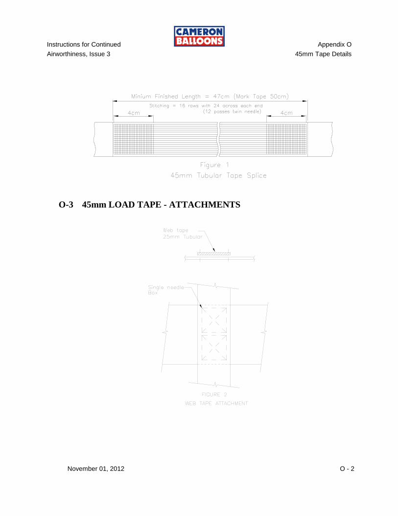
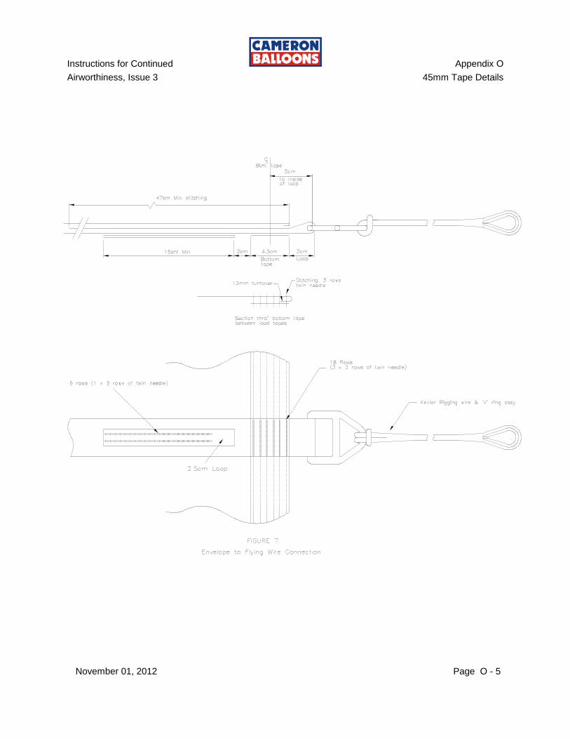
The overlap must be 50cm (20") prior to sewing (see Figure 1). After sewing the splice this dimension will be reduced, due to sewing shrinkage, to now less than 47cm (18.5"). The splice must be made in the load tape alone, without the fabric attached. After the splice has been completed, sew the load tape to the fabric. When sewing the load tape splice, as noted above, leave enough excess load tape length to allow for the shrinkage which will occur when the splice is sewn. If estimated correctly, this will result in the length of the spliced load tape being the same length as the fabric seam or fabric edge which subsequently must be sewn to it. This precaution will make sewing of the final seam easier.
45mm tubular polyester load tape splice must be sewn with 16 parallel rows of stitching and 24 across each end (12 passes of twin needle) of the splice (in other words, sewn across the tape, back and across again).
The needle size for splicing tubular load tape may be up to 140.
Instructions for Continued Appendix O
Airworthiness, Issue 3 45mm Tape Details
November 01, 2012 O - 2
O-3 45mm LOAD TAPE - ATTACHMENTS

Instructions for Continued Appendix O
Airworthiness, Issue 3 45mm Tape Details
November 01, 2012 Page O - 3
Instructions for Continued Appendix O
Airworthiness, Issue 3 45mm Tape Details
November 01, 2012 O - 4
Instructions for Continued Appendix O
Airworthiness, Issue 3 45mm Tape Details
November 01, 2012 Page O - 5
Instructions for Continued Appendix O
Airworthiness, Issue 3 45mm Tape Details
November 01, 2012 O - 6
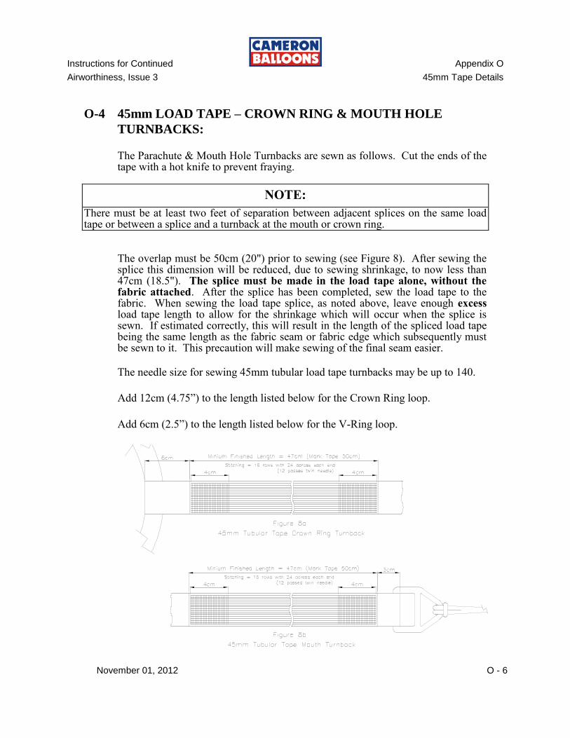
O-4 45mm LOAD TAPE – CROWN RING & MOUTH HOLE
TURNBACKS:
The Parachute & Mouth Hole Turnbacks are sewn as follows. Cut the ends of the tape with a hot knife to prevent fraying.
NOTE:
There must be at least two feet of separation between adjacent splices on the same load tape or between a splice and a turnback at the mouth or crown ring.
The overlap must be 50cm (20") prior to sewing (see Figure 8). After sewing the splice this dimension will be reduced, due to sewing shrinkage, to now less than 47cm (18.5"). The splice must be made in the load tape alone, without the fabric attached. After the splice has been completed, sew the load tape to the fabric. When sewing the load tape splice, as noted above, leave enough excess load tape length to allow for the shrinkage which will occur when the splice is sewn. If estimated correctly, this will result in the length of the spliced load tape being the same length as the fabric seam or fabric edge which subsequently must be sewn to it. This precaution will make sewing of the final seam easier.
The needle size for sewing 45mm tubular load tape turnbacks may be up to 140.
Add 12cm (4.75”) to the length listed below for the Crown Ring loop.
Add 6cm (2.5”) to the length listed below for the V-Ring loop.
Instructions for Continued Appendix O
Airworthiness, Issue 3 45mm Tape Details
November 01, 2012 Page O - 7
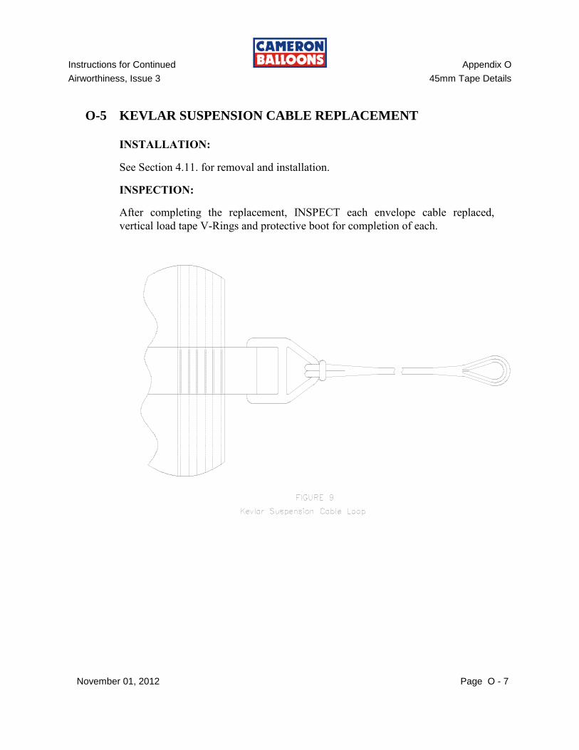
O-5 KEVLAR SUSPENSION CABLE REPLACEMENT
INSTALLATION: See Section 4.11. for removal and installation. INSPECTION:
After completing the replacement, INSPECT each envelope cable replaced,
vertical load tape V-Rings and protective boot for completion of each.
Instructions for Continued Appendix O
Airworthiness, Issue 3 45mm Tape Details
November 01, 2012 O - 8
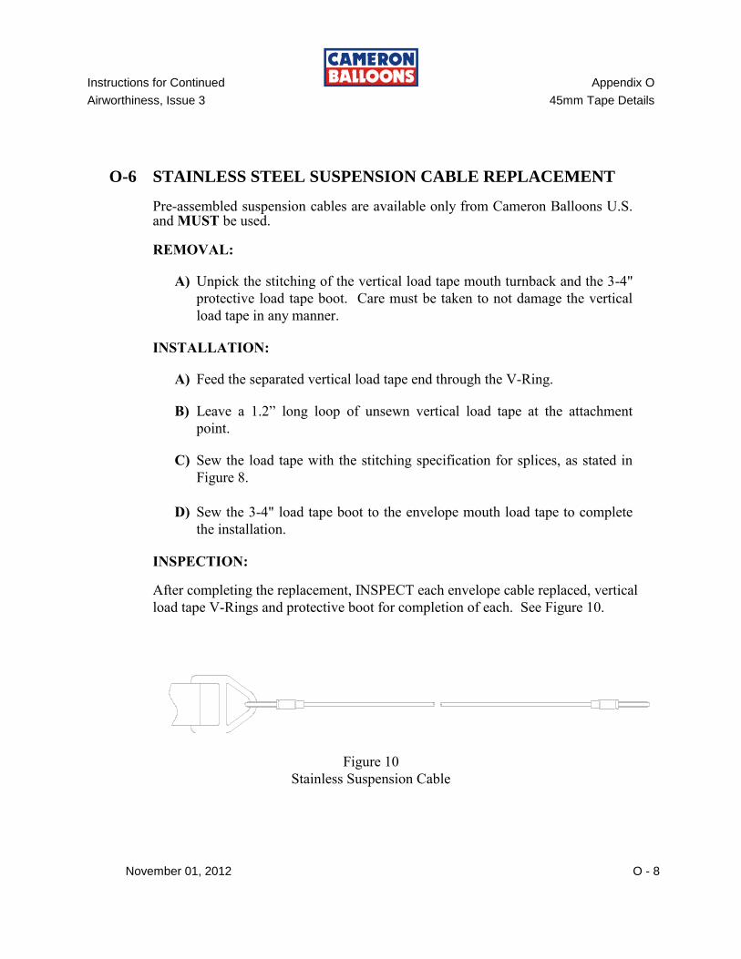
O-6 STAINLESS STEEL SUSPENSION CABLE REPLACEMENT
Pre-assembled suspension cables are available only from Cameron Balloons U.S. and MUST be used. REMOVAL:
A) Unpick the stitching of the vertical load tape mouth turnback and the 3-4"
protective load tape boot. Care must be taken to not damage the vertical
load tape in any manner.
INSTALLATION:
A) Feed the separated vertical load tape end through the V-Ring.
B) Leave a 1.2” long loop of unsewn vertical load tape at the attachment
point.
C) Sew the load tape with the stitching specification for splices, as stated in
Figure 8.
D) Sew the 3-4" load tape boot to the envelope mouth load tape to complete
the installation.
INSPECTION:
After completing the replacement, INSPECT each envelope cable replaced, vertical
load tape V-Rings and protective boot for completion of each. See Figure 10.
Figure 10
Stainless Suspension Cable
Instructions for Continued Appendix O
Airworthiness, Issue 3 45mm Tape Details
November 01, 2012 Page O - 9
O-7 PARACHUTE & MOUTH OPENING LOAD TAPE SPLICE
The horizontal load tape at the edge of the parachute hole and mouth hole is 45mm tubular load tape of the same specifications as tubular vertical load tapes. The ends of this tape must be spliced the same as the vertical load tapes, specified in Fig. 1. The vertical load tapes pass under the parachute hole tape. The length of the parachute hole tape is important for the proper fit of the parachute. The dimensions of this tape should be verified with Cameron Balloons U.S. if any splicing will be done on this tape.
NOTE:
ORDER PRE-CUT, PRE-MEASURED AND PRE-MARKED PARACHUTE HOLE TOP TAPES FROM CAMERON BALLOONS TO ASSURE THE CORRECT REPLACEMENT OF TOP TAPES DURING TOP FABRIC REBUILDS.
O-8 ALLOWABLE DAMAGE
A) 45mm VERTICAL LOAD TAPES
Breaks of fewer than four filaments (vertical or horizontal) is permitted,
provided that no more than one vertical tape is damaged.
B) V-RING
No damage what so ever is permitted.
Consult Cameron Balloons if questions arise on the airworthiness or legality of a repair, installation, or equipment damage.

Instructions for Continued Appendix O
Airworthiness, Issue 3 45mm Tape Details
November 01, 2012 O - 10
THIS PAGE INTENTIONALLY BLANK
Instructions for Continued Appendix Q
Airworthiness, Issue 3 Fuel Tank Strap Installation
November 01, 2012 Page Q 1
WARNING! DANGER! HAZARDOUS CONDITIONS WHICH COULD RESULT IN INJURY OR
DEATH MAY OCCUR FROM:
A. THE INSTALLATION OF NON-APPROVED PARTS OR
MATERIALS
B. MODIFICATION OF ANY PART
C. IMPROPER REPAIR PROCEDURES
D. IMPROPER OPERATION OF THIS AIRCRAFT
E. THE IMPROPER INSTALLATION OR ROUTING OF ANY TANK
STRAP(S)
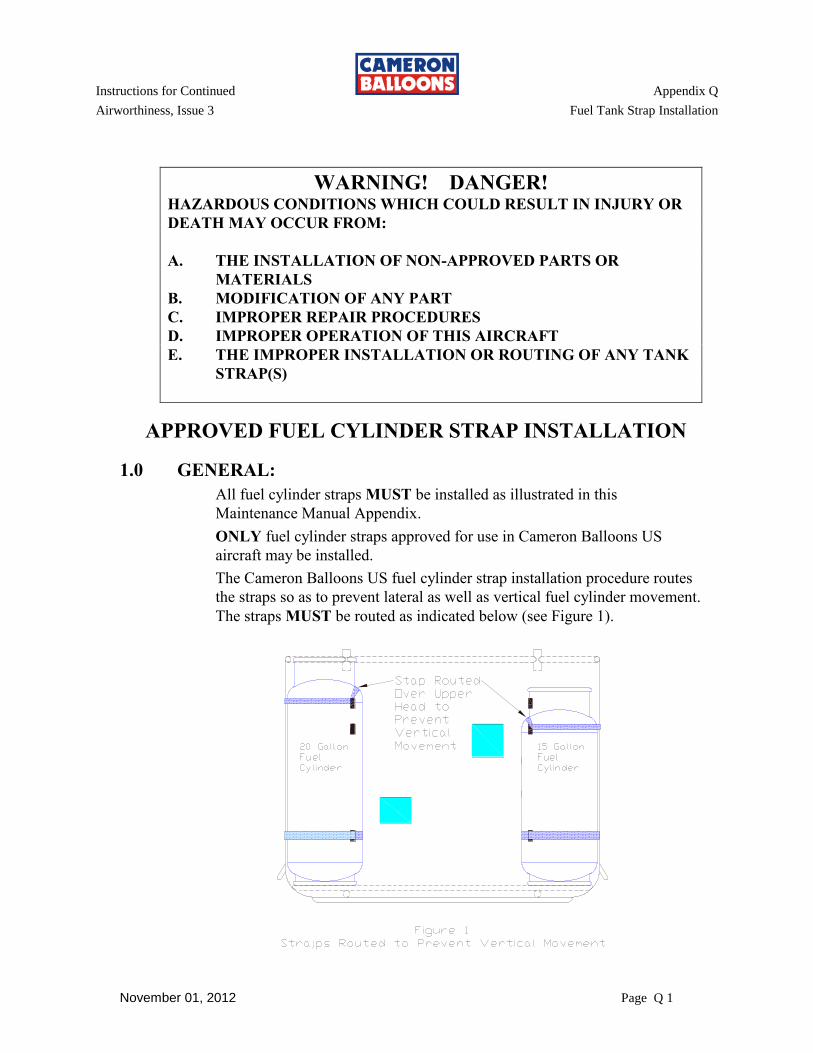
APPROVED FUEL CYLINDER STRAP INSTALLATION
1.0 GENERAL:
All fuel cylinder straps MUST be installed as illustrated in this
Maintenance Manual Appendix.
ONLY fuel cylinder straps approved for use in Cameron Balloons US
aircraft may be installed.
The Cameron Balloons US fuel cylinder strap installation procedure routes
the straps so as to prevent lateral as well as vertical fuel cylinder movement.
The straps MUST be routed as indicated below (see Figure 1).
Instructions for Continued Appendix Q
Airworthiness, Issue 3 Fuel Tank Strap Installation
November 01, 2012 Page Q 2
Each fuel cylinder is secured with a minimum of two straps. Depending
on the age and style of basket there are 3 widths of approved Cameron
Balloons US fuel cylinder straps, 1 inch, 1.5 inch and 2 inch.
Aristocrat (serial numbers greater than 8800) and Regular Spec Top Frame
Open baskets may use any Cameron Balloons US approved 10, 11 or 15
gallon fuel cylinder. High Spec Top Frame Open and T and TT-partition
baskets may use any Cameron Balloons US approved 10, 11, 15 or 20
gallon fuel cylinder.
Aristocrat Baskets, Top Frame Open Baskets: The locations of the
strap holes and strap routing are obvious.
Sport Baskets: The location of the pass through points are: on the long
side; vertically, between the hi-light weave rows and horizontally, around
the U-tube. On the short side; vertically, between the hi-light weave rows
and horizontally, around the heavy vertical tank reinforcement up-right.
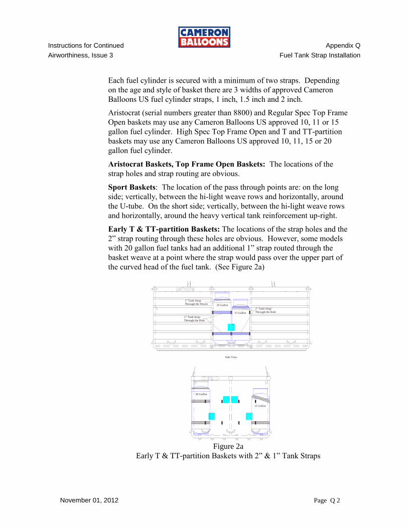
Early T & TT-partition Baskets: The locations of the strap holes and the
2” strap routing through these holes are obvious. However, some models
with 20 gallon fuel tanks had an additional 1” strap routed through the
basket weave at a point where the strap would pass over the upper part of
the curved head of the fuel tank. (See Figure 2a)
Figure 2a
Early T & TT-partition Baskets with 2” & 1” Tank Straps
20 Gallon
15 Gallon
1" Tank Strap
Through the Weave
2" Tank Strap
Through the Hole
2" Tank Strap
Through the Hole
20 Gallon
15 Gallon
Side View
End View
Instructions for Continued Appendix Q
Airworthiness, Issue 3 Fuel Tank Strap Installation
November 01, 2012 Page Q 3
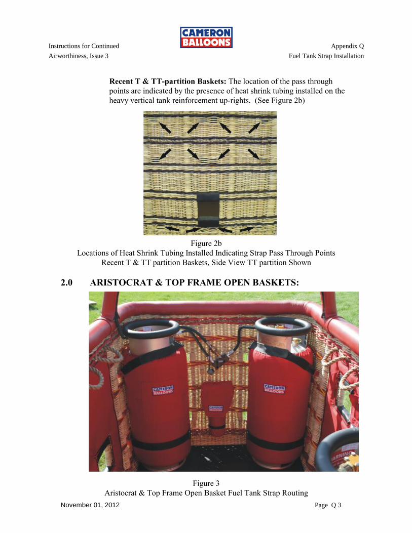
Recent T & TT-partition Baskets: The location of the pass through
points are indicated by the presence of heat shrink tubing installed on the
heavy vertical tank reinforcement up-rights. (See Figure 2b)
Figure 2b
Locations of Heat Shrink Tubing Installed Indicating Strap Pass Through Points
Recent T & TT partition Baskets, Side View TT partition Shown
2.0 ARISTOCRAT & TOP FRAME OPEN BASKETS:
Figure 3
Aristocrat & Top Frame Open Basket Fuel Tank Strap Routing
Instructions for Continued Appendix Q
Airworthiness, Issue 3 Fuel Tank Strap Installation
November 01, 2012 Page Q 4
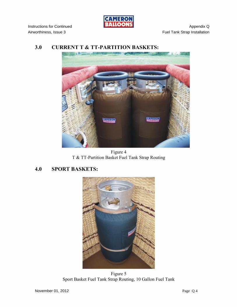
3.0 CURRENT T & TT-PARTITION BASKETS:
Figure 4
T & TT-Partition Basket Fuel Tank Strap Routing
4.0 SPORT BASKETS:
Figure 5
Sport Basket Fuel Tank Strap Routing, 10 Gallon Fuel Tank
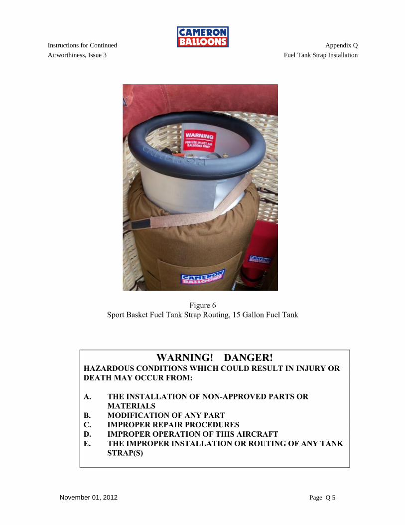
Instructions for Continued Appendix Q
Airworthiness, Issue 3 Fuel Tank Strap Installation
November 01, 2012 Page Q 5
Figure 6
Sport Basket Fuel Tank Strap Routing, 15 Gallon Fuel Tank
WARNING! DANGER! HAZARDOUS CONDITIONS WHICH COULD RESULT IN INJURY OR
DEATH MAY OCCUR FROM:
A. THE INSTALLATION OF NON-APPROVED PARTS OR
MATERIALS
B. MODIFICATION OF ANY PART
C. IMPROPER REPAIR PROCEDURES
D. IMPROPER OPERATION OF THIS AIRCRAFT
E. THE IMPROPER INSTALLATION OR ROUTING OF ANY TANK
STRAP(S)

Instructions for Continued Appendix Q
Airworthiness, Issue 3 Fuel Tank Strap Installation
November 01, 2012 Page Q 6
THIS PAGE INTENTIONALLY BLANK
Instructions for Continued Appendix R
Airworthiness, Issue 3 Airworthiness Limitations
November 01, 2012 Page 1 of 2
APPENDIX R
AIRWORTHINESS LIMITATIONS
Note: The Airworthiness Limitations section is FAA-approved and specifies maintenance
required under section 43.16 and 91.403 of the Federal Aviation Regulations unless an
alternative program has been established.
R-1 There are no Airworthiness Limitations applicable to Cameron Balloons aircraft.
R-2 AIRCRAFT ANNUAL/100 HOUR INSPECTION:
The balloon must be inspected each 100 hours of operation or annually, whichever
comes first. The 100 Hour and Annual Inspections are identical. Both use ICA
Appendix B, “INSPECTION CHECK LIST, ANNUAL/100 HOUR”.

Instructions for Continued Appendix R
Airworthiness, Issue 3 Airworthiness Limitations
November 01, 2012 Page 2 of 2
THIS PAGE INTENTIONALLY BLANK

Instructions for Continued Appendix S
Airworthiness, Issue 3 Stratus Burner
November 01, 2012 Page 1
1. STRATUS BURNER: GENERAL
Prior to any disassembly work being done on the burner, ensure that the burner has been
vented and all fuel pressure has been removed.
If any components require replacement use only approved Cameron Balloons US spare
parts.
Following any maintenance and prior to further use, the burner must be pressure tested.
Any items worked on must be subjected to an under pressure function test.
Any maintenance must be entered into the appropriate log book.
MAIN BURNER
GIMBAL BLOCK
PRESSURE GAUGE
PILOT LIGHT
LIQUID FIRE
Figure 1: GENERAL ASSEMBLY

Instructions for Continued Appendix S
Airworthiness, Issue 3 Stratus Burner
November 01, 2012 Page 2
2. MAIN BLAST VALVE: Figure 2
To gain access to the main blast valve the burner handle must be removed.
1) Use an allen wrench (4mm) to remove the four handle retaining bolts (53025).
2) Remove the handle (F8529), the blast valve trigger assembly (F8566) and handle boss
(F8528 or F8579).
3) Use a 30mm wrench (or special tool F115X) to unscrew and remove the valve bonnet
assembly (F8523 or F8581).
4) Remove the valve stem assembly.
5) Clean and inspect all parts.
6) Replace o-ring (F128R) and Teflon backup ring (F128T).
CAUTION: On re-assembly the stem o-ring and Teflon ring should be smeared
with silicone grease.
7) Re-assembly in the reverse order.
CAUTION: Take care to install the superseal in the correct orientation and the
stem o-ring and stem Teflon ring in the right order.
NOTE: There are no torque specs for the bonnet assembly. Tighten until snug.
NOTE: The internal parts of the Main Blast Valve are the same as those in the
Liquid Fire Valve
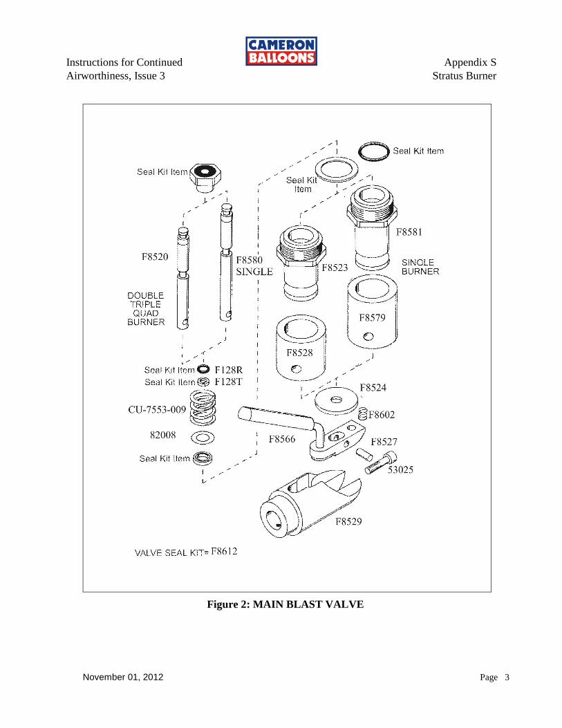
Instructions for Continued Appendix S
Airworthiness, Issue 3 Stratus Burner
November 01, 2012 Page 3
Figure 2: MAIN BLAST VALVE
Instructions for Continued Appendix S
Airworthiness, Issue 3 Stratus Burner
November 01, 2012 Page 4
3. LIQUID FIRE VALVE: Figure 3
1) Remove the circlip (F8300) and pivot pin (F8227) from the toggle handle.
2) Use a wrench (30mm) (or special tool F115X) to unscrew and remove the valve bonnet
assembly (F8521).
3) Remove the valve stem assembly.
4) Clean and inspect all parts.
5) Replace o-ring (F128R) and Teflon backup ring (F128T).
CAUTION: On re-assembly the stem o-ring and Teflon ring should be smeared
with silicone grease.
6) Re-assembly in the reverse order.
CAUTION: Take care to install the superseal in the correct orientation and the
stem o-ring and stem Teflon ring in the right order.
NOTE: There are no torque specs for the bonnet assembly. Tighten until snug.
NOTE: The internal parts of the Main Blast Valve are the same as those in the
Liquid Fire Valve
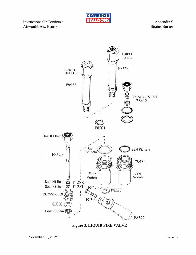
Instructions for Continued Appendix S
Airworthiness, Issue 3 Stratus Burner
November 01, 2012 Page 5
Figure 3: LIQUID FIRE VALVE
Instructions for Continued Appendix S
Airworthiness, Issue 3 Stratus Burner
November 01, 2012 Page 6
4. UPPER PILOT LIGHT: Figure 4
1) Remove the regulator and flame cup with Cameron special tool (F115X) or a 30mm
crowfoot wrench. This will either separate the regulator upper body (F8556) from its
lower half (F8545) or extract the complete regulator assembly from the valve block.
NOTE: Take care not to damage the igniter electrode when performing this
procedure.
2) Unscrew the regulator upper body from its lower half (if necessary) and remove the
spring (F8539) and piston assembly (F8624).
NOTE: DO NOT clamp the regulator upper body in a vice or other tool as this
can distort the part, which could cause incorrect operation.
3) Unscrew the flame tube (F8517) from the regulator upper body (F8566) to reveal the
pilot light jet (F8013).
4) Unscrew the jet (F8013) to reveal the filter (F8546).
NOTE: If either of these items appears to be blocked or contaminated they should
be replaced or thoroughly cleaned using a hydrocarbon solvent before
being refitted.
5) Inspect the inside of the regulator upper body (F8556) and piston assembly for
contamination. Clean with solvent and lent free cloth.
6) Check that the rubber seal on the end of the piston and piston o-rings are in good
condition and secure. If any are damaged it must be replaced.
7) If necessary, lightly lubricate the piston sealing o-rings with silicone spray and install
the piston into the upper body.
NOTE: Take care not to damage the white sealing ring on the screw thread inside
the upper body.
8) Install the regulator spring and screw the upper and lower bodies together.
9) Install the pilot light flame tube onto the regulator ensuring the parts are tightly screwed
together.
NOTE: The air regulator (F8565) should cover only one of the two intake holes.
10) Install the pilot light assembly into the valve block taking care that the lower body o-
ring is in the correct position.
11) Adjust the igniter electrode to a gap of 4-6mm (5/32” to 1/4") and ensure the spark
jumps to the edge of one of the flame cup holes.
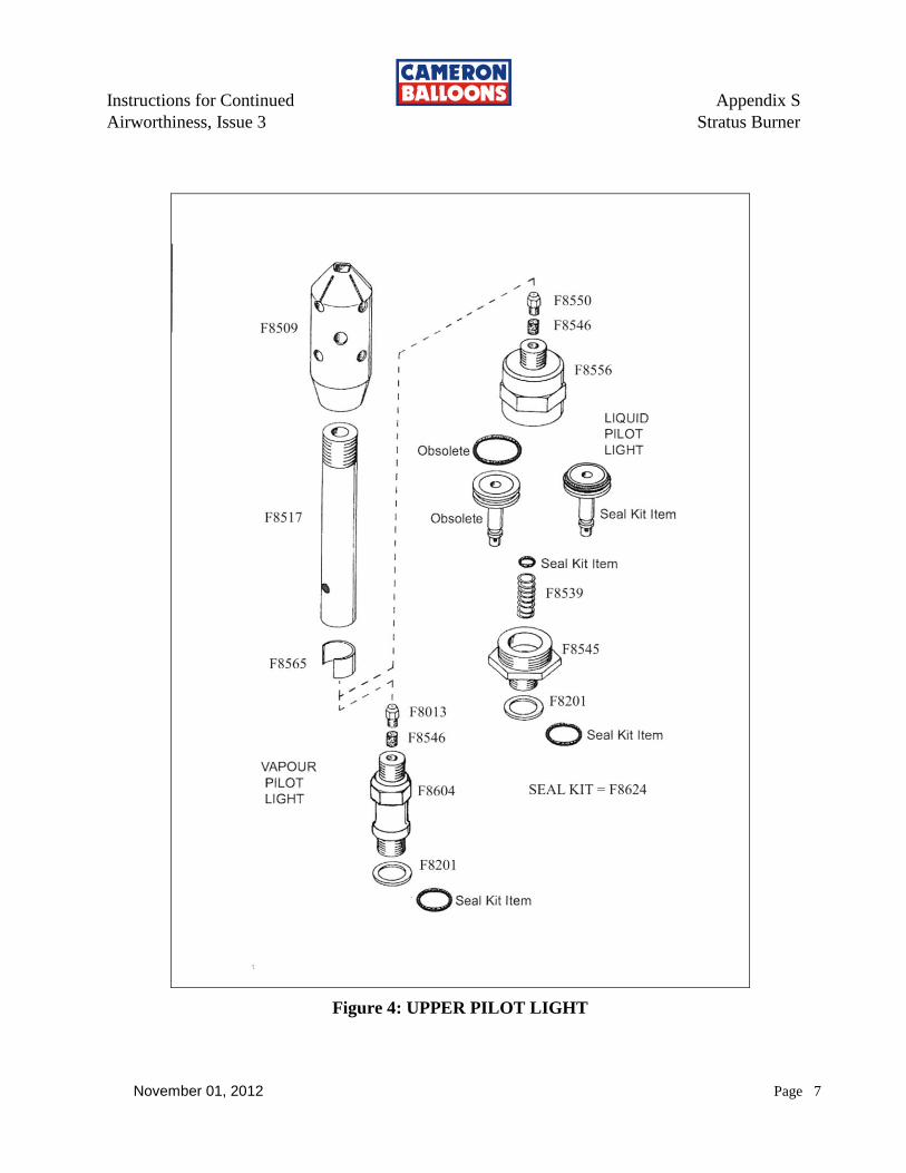
Instructions for Continued Appendix S
Airworthiness, Issue 3 Stratus Burner
November 01, 2012 Page 7
Figure 4: UPPER PILOT LIGHT
Instructions for Continued Appendix S
Airworthiness, Issue 3 Stratus Burner
November 01, 2012 Page 8
5. LOWER PILOT LIGHT: Figure 5
1) Remove the handle (F8514) by unscrewing the attaching bolt (33016).
2) Remove the handle dowel (F8515) from the valve block.
NOTE: The dowel has a small flat on its diameter where it is in contact with the
handle.
3) Unscrew the pilot valve nut (F8512). Special tool F115Y is required.
NOTE: Firm pressure must be maintained to keep the tool engaged.
4) Remove the stem assembly.
5) Clean and inspect all parts.
6) Replace o-ring (F128R) and Teflon backup ring (F128T).
CAUTION: On re-assembly the stem o-ring and Teflon ring should be smeared
with silicone grease.
7) Re-assembly in the reverse order.
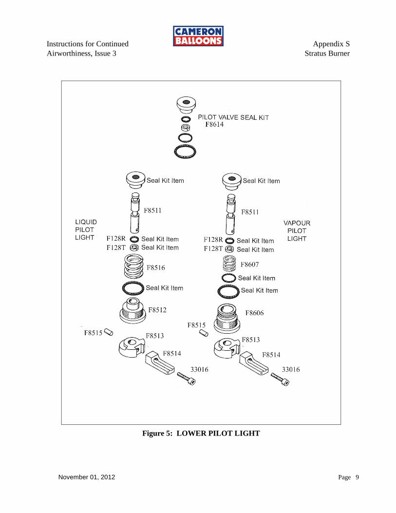
Instructions for Continued Appendix S
Airworthiness, Issue 3 Stratus Burner
November 01, 2012 Page 9
Figure 5: LOWER PILOT LIGHT
Instructions for Continued Appendix S
Airworthiness, Issue 3 Stratus Burner
November 01, 2012 Page 10
6. PIEZO IGNITER: Figure 6
1) Move the pilot light valve handle to the on position to reveal the piezo igniter housing.
2) Unscrew the piezo igniter assembly from the block. Special tool F115Y is required.
3) Mark the position of the electrode tip onto the outside of the housing (F8506)
(important for reassemble).
CAUTION: The igniter electrode ceramic insulator is very brittle, using
excessive force may cause it to shatter.
4) Unscrew the lock nut on the electrode (F8561) and then unscrew the piezo push-button
generator (F8505).
5) Replace any defective items and then careful re-insert the parts into the housing,
ensuring that both ends of the lead (F8508) remain firmly plugged onto the terminals.
6) Tighten the push-button generator into the housing.
7) Adjust the electrode to be in line with the mark made in step 3 then tighten the
electrode lock nut.
8) Inspect the o-ring, replace if necessary. Install the o-ring onto the housing.
9) Insert the Piezo Igniter into the block and tighten.
10) Insure the spark gap is 4-6mm (5/32” to 1/4") and the spark jumps to the edge of one of
the flame cup holes.
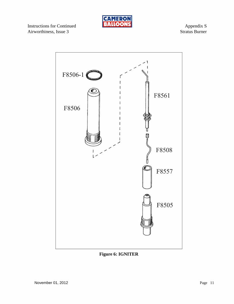
Instructions for Continued Appendix S
Airworthiness, Issue 3 Stratus Burner
November 01, 2012 Page 11
Figure 6: IGNITER
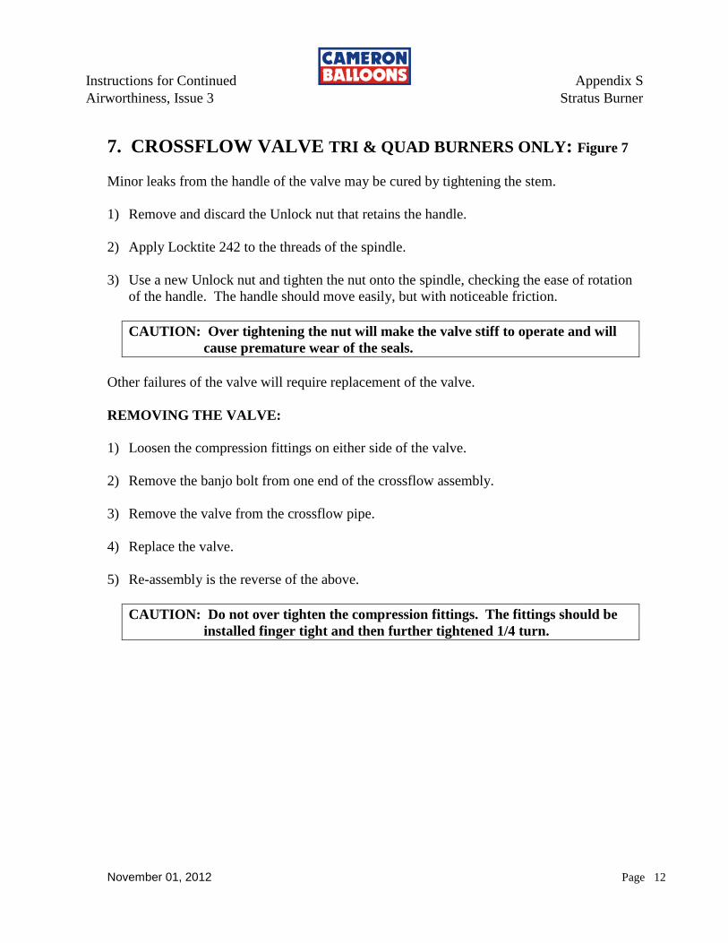
Instructions for Continued Appendix S
Airworthiness, Issue 3 Stratus Burner
November 01, 2012 Page 12
7. CROSSFLOW VALVE TRI & QUAD BURNERS ONLY: Figure 7
Minor leaks from the handle of the valve may be cured by tightening the stem.
1) Remove and discard the Unlock nut that retains the handle.
2) Apply Locktite 242 to the threads of the spindle.
3) Use a new Unlock nut and tighten the nut onto the spindle, checking the ease of rotation
of the handle. The handle should move easily, but with noticeable friction.
CAUTION: Over tightening the nut will make the valve stiff to operate and will
cause premature wear of the seals.
Other failures of the valve will require replacement of the valve.
REMOVING THE VALVE:
1) Loosen the compression fittings on either side of the valve.
2) Remove the banjo bolt from one end of the crossflow assembly.
3) Remove the valve from the crossflow pipe.
4) Replace the valve.
5) Re-assembly is the reverse of the above.
CAUTION: Do not over tighten the compression fittings. The fittings should be
installed finger tight and then further tightened 1/4 turn.

Instructions for Continued Appendix S
Airworthiness, Issue 3 Stratus Burner
November 01, 2012 Page 13
Figure 7: CROSSFLOW VALVE
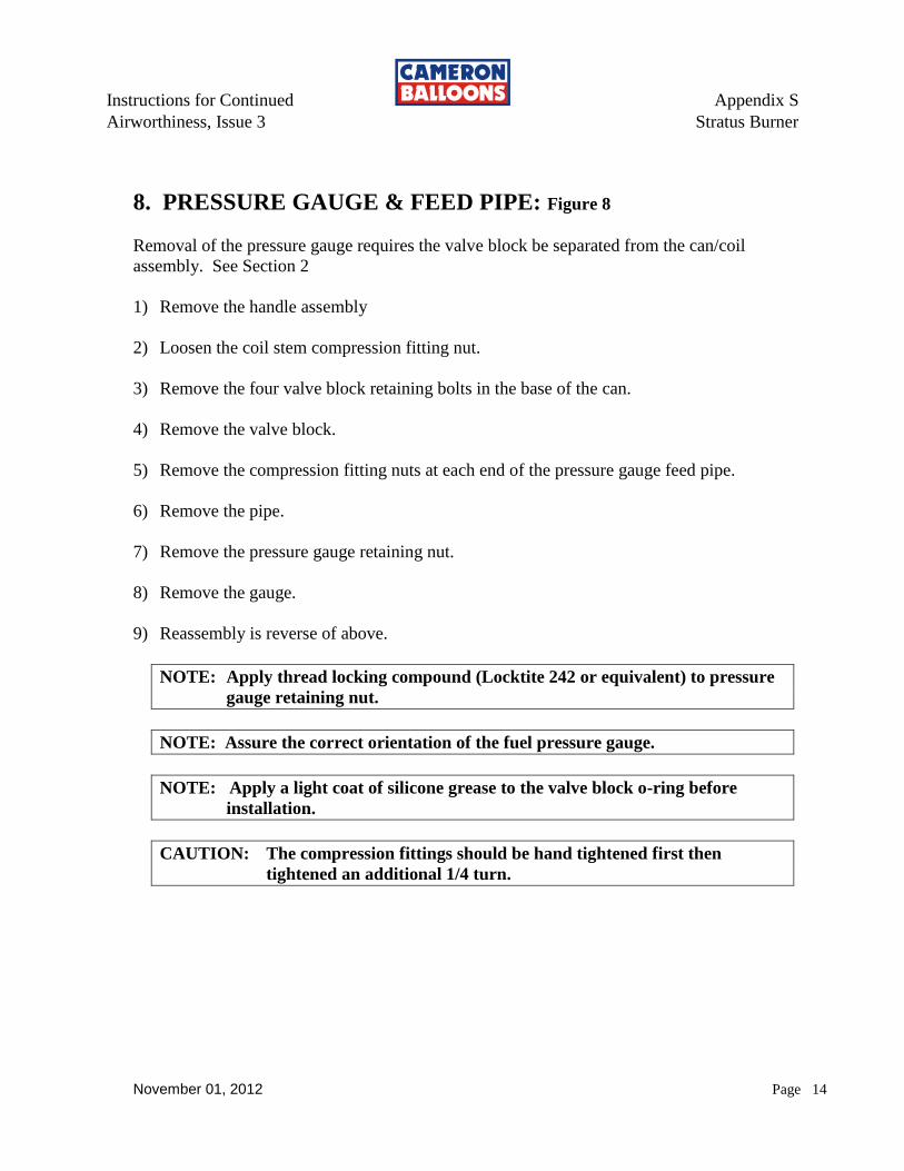
Instructions for Continued Appendix S
Airworthiness, Issue 3 Stratus Burner
November 01, 2012 Page 14
8. PRESSURE GAUGE & FEED PIPE: Figure 8
Removal of the pressure gauge requires the valve block be separated from the can/coil
assembly. See Section 2
1) Remove the handle assembly
2) Loosen the coil stem compression fitting nut.
3) Remove the four valve block retaining bolts in the base of the can.
4) Remove the valve block.
5) Remove the compression fitting nuts at each end of the pressure gauge feed pipe.
6) Remove the pipe.
7) Remove the pressure gauge retaining nut.
8) Remove the gauge.
9) Reassembly is reverse of above.
NOTE: Apply thread locking compound (Locktite 242 or equivalent) to pressure
gauge retaining nut.
NOTE: Assure the correct orientation of the fuel pressure gauge.
NOTE: Apply a light coat of silicone grease to the valve block o-ring before
installation.
CAUTION: The compression fittings should be hand tightened first then
tightened an additional 1/4 turn.
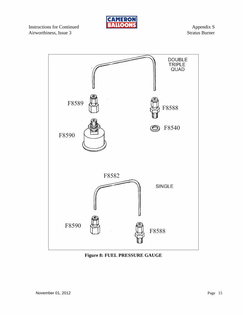
Instructions for Continued Appendix S
Airworthiness, Issue 3 Stratus Burner
November 01, 2012 Page 15
Figure 8: FUEL PRESSURE GAUGE
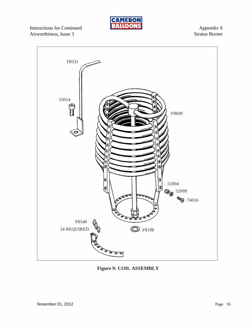
Instructions for Continued Appendix S
Airworthiness, Issue 3 Stratus Burner
November 01, 2012 Page 16
F8531
53014
F8600
51004
52009
74016
F8198
F8548
24 REQUIRED
Figure 9: COIL ASSEMBLY
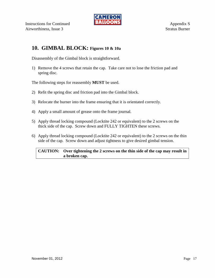
Instructions for Continued Appendix S
Airworthiness, Issue 3 Stratus Burner
November 01, 2012 Page 17
10. GIMBAL BLOCK: Figures 10 & 10a
Disassembly of the Gimbal block is straightforward.
1) Remove the 4 screws that retain the cap. Take care not to lose the friction pad and
spring disc.
The following steps for reassembly MUST be used.
2) Refit the spring disc and friction pad into the Gimbal block.
3) Relocate the burner into the frame ensuring that it is orientated correctly.
4) Apply a small amount of grease onto the frame journal.
5) Apply thread locking compound (Locktite 242 or equivalent) to the 2 screws on the
thick side of the cap. Screw down and FULLY TIGHTEN these screws.
6) Apply thread locking compound (Locktite 242 or equivalent) to the 2 screws on the thin
side of the cap. Screw down and adjust tightness to give desired gimbal tension.
CAUTION: Over tightening the 2 screws on the thin side of the cap may result in
a broken cap.
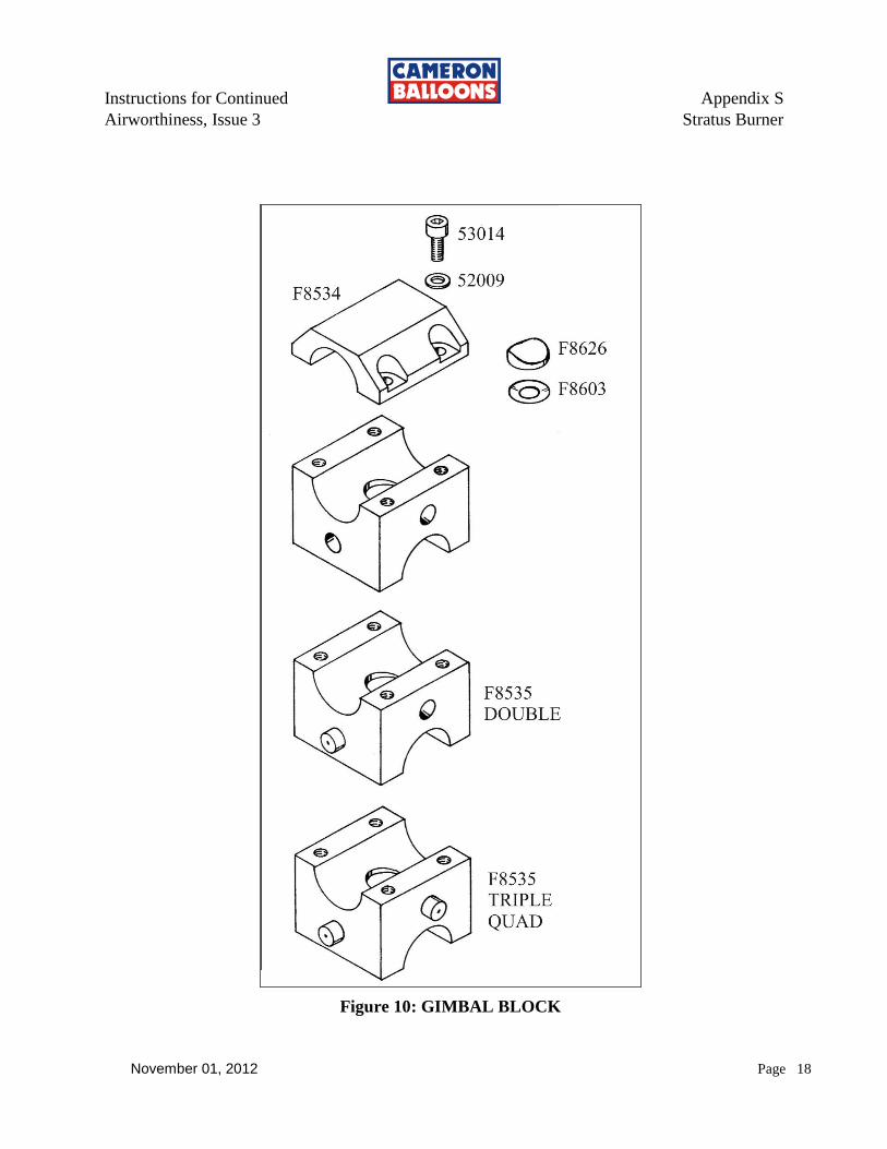
Instructions for Continued Appendix S
Airworthiness, Issue 3 Stratus Burner
November 01, 2012 Page 18
Figure 10: GIMBAL BLOCK

Instructions for Continued Appendix S
Airworthiness, Issue 3 Stratus Burner
November 01, 2012 Page 19
Figure 10a: GIMBAL BLOCK, M8 Stud
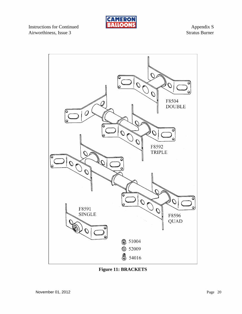
Instructions for Continued Appendix S
Airworthiness, Issue 3 Stratus Burner
November 01, 2012 Page 20
Figure 11: BRACKETS
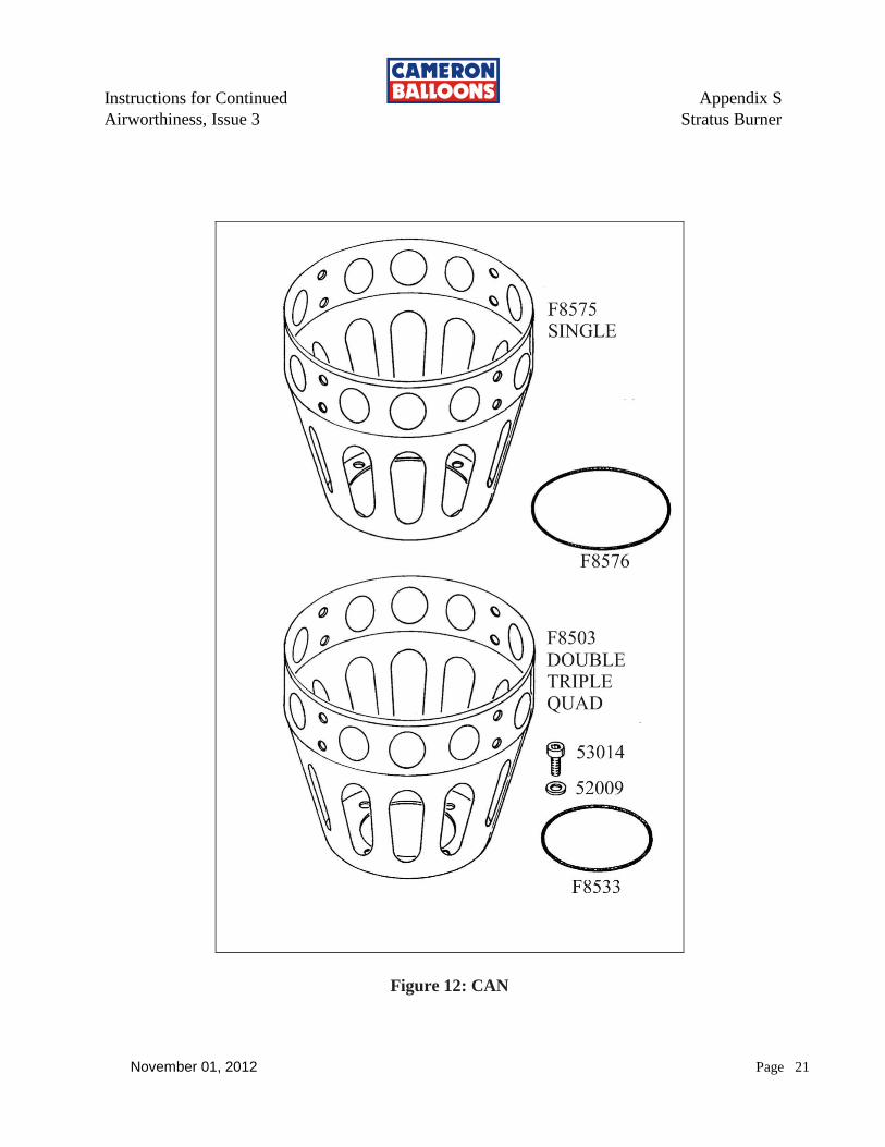
Instructions for Continued Appendix S
Airworthiness, Issue 3 Stratus Burner
November 01, 2012 Page 21
Figure 12: CAN
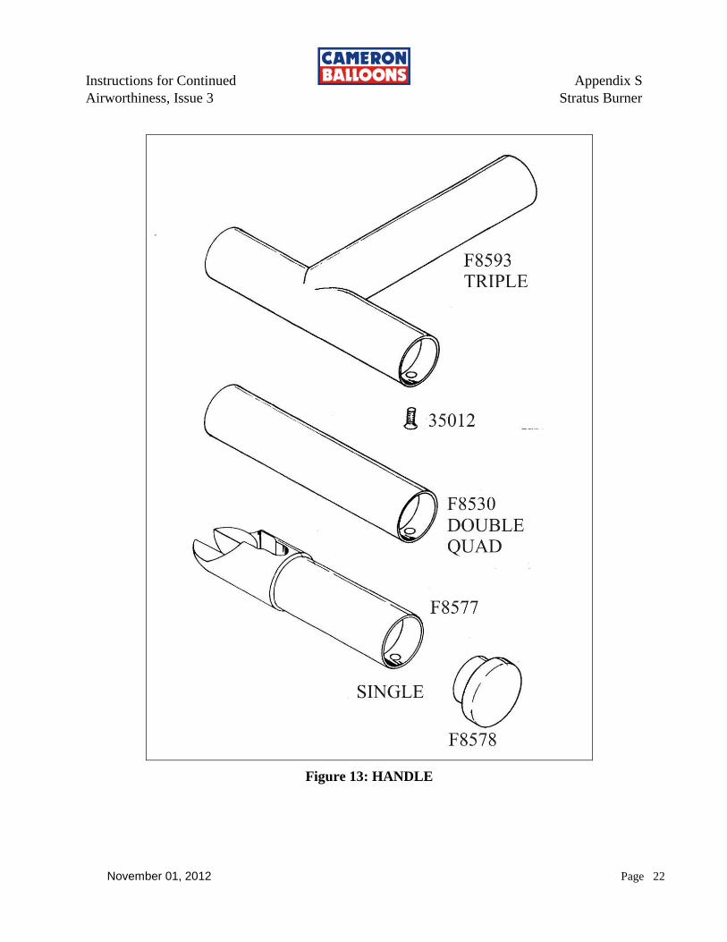
Instructions for Continued Appendix S
Airworthiness, Issue 3 Stratus Burner
November 01, 2012 Page 22
Figure 13: HANDLE

Instructions for Continued Appendix S
Airworthiness, Issue 3 Stratus Burner
November 01, 2012 Page 23
11. Required Maintenance at Annual/100 hr Inspection
1. Tighten the Main Burner Jets
2. Blast Valves MUST be Disassembled, Cleaned, Inspected & Lubricated
3. If Liquid Pilot Lights are used, Disassemble and Clean Regulator
4. Remove and Clean Pilot Light Jet & Filter
5. Liquid Fire Valves MUST be Disassembled, Cleaned, Inspected & Lubricated
Blast Valves & Liquid Fire O-rings & Teflon rings
MUST be Replaced

Instructions for Continued Appendix S
Airworthiness, Issue 3 Stratus Burner
November 01, 2012 Page 24
THIS PAGE INTENTIONALLY BLANK
Instructions for Continued Appendix T
Airworthiness, Issue 3 Flytec model 3040
November 01, 2012 Page T - 1
APPENDIX T
Flytec Model 3040
P-1 GENERAL
This Appendix specifies repair and inspection procedures for aircraft that use Flytec model 3040. The only repair and maintenance that may be performed by the owner/operator is to change the batteries in the receiver and temperature transmitter. The only repair and maintenance that may be performed by a certified repair person is to change the batteries in the receiver and temperature transmitter and at Annual/100 hour Inspection to check the envelope temperature accuracy is ± 4º F at the boiling point of water adjusted for altitude.
P-2 BATTERY REPLACEMENT
At Annual/100 hour Inspection the batteries in the receiver and
temperature transmitter (if disposable) MUST be replaced. If the batteries
are re-chargeable, they should be re-charged at the earliest convenience.
The batteries in the model 3040 receiver are replaced by removing the
single screw centered in the back of the receiver just above the stainless
steal clip. Once this screw is removed gently pry the clip away from the
instrument and lift and slide the battery door from the rear housing. The
battery door fits snugly in the rear housing, so it may be necessary to insert
a blunt tool into the battery door screw hole to help pry the door from its
recess.
The battery in the temperature transmitter is replaced by removing the 4
screws in the back of the housing and separating the front from the rear.
When reassembling the front and rear housings care should be give to
ensure that the sensor wire silicone strain relief grommets are in place and
seated properly.
Instructions for Continued Appendix T
Airworthiness, Issue 3 Flytec model 3040
November 01, 2012 T - 2
P-3 CHECKING TEMPERATURE ACCURACY AT
ANNUAL/100 HOUR INSPECTIONS
The temperature transmitter sensor (located on the end of the temperature
sensor cable) may be directly submerged in water.
Note: DO NOT SUBMERGE THE ENTIRE TEMPERATURE
TRANSMITTER UNIT IN WATER. DAMAGE WILL OCCUR.
1) Submerge the temperature transmitter sensor into boiling water.
2) Wait until the temperature readout stabilizes.
3) Record the temperature.
The temperature reading should be ± 4º F at the boiling point of water
adjusted for altitude.
If the temperature reading is out of this range, it must be returned to Flytec
USA for repair.
P-4 ALL OTHER REPAIRS
Repairs other than changing batteries, must be performed by a Certified
Instrument rated repair facility or by Flytec USA.
Flytec USA
1126 Seminole Drive
Indian Harbor Beach, FL 32937
800-662-2449
www.flytec.com
Instructions for Continued Appendix U
Airworthiness, Issue 3 Burner Friction Force
November 01, 2012 Page 1 of 4
APPENDIX U
BURNER GIMBAL FRICTION FORCE
There are two types of burner gimbal systems. One is the ‘Saddle Assembly System’ and the
other is the ‘Gimbal Block System’. Currently the Saddle Assembly System is used on all MK
IV Standard burners, all MK IV Super burners, all MK IV Ultra Single burners and early MK IV
Ultra Double, Triple and Quad burners. The Gimbal Block System is used on current MK IV
Ultra Double, Triple and Quad burners and on all Sirocco burners. The various types and styles
of gimbal system can be visually identified using the following diagrams (Figures 1, 2 and 3).
The Saddle Assembly System utilizes an inner and outer frame, connected together with a bolt,
saddles, friction washer, nuts and washers. There are two different saddle assemblies, the
original – Style ‘A’ (Figure 1) and the newer – Style ‘B’ (Figure 2). Style ‘B’ has an ‘Angle
Limiting System’ incorporated into it.
The Gimbal Block System utilizes a custom manufactured assembly consisting of a frame bridge,
main block and two caps. There are two different Gimbal Block Assemblies, ‘Type One’ which
uses allen head cap screws and lock washers to connect the caps to the main block and ‘Type
Two’ which uses studs, locking nuts and washers to connect the caps to the main block (both
Styles are shown in Figure 3). Both Gimbal Block styles have an ‘Angle Limiting System’
incorporated into it.
FRICTION FORCE ADJUSTMENT (MOVEMENT TENSION)
Burner gimbal movement tension is adjusted to pilot preference (and is considered
Preventive Maintenance). There is no torque specification; however the recommended minimum
friction force should be strong enough to stop the burner from moving when no intentional force
is applied to it.
Saddle Assembly:
1) Fit a wrench to the bolt head and hold tightly.
2) Fit an open-end wrench (ground to the same thickness as the ‘Thin Nut’) to the ‘Thin
Nut’.
3) Tighten the ‘Thin Nut’ to the desired tightness /friction setting.
4) Remove the wrench from the bolt head and fit it to the ‘Thick Nut’.
5) Tighten the ‘Thick Nut’ against the ‘Thin Nut’ assuring that the “Thin Nut’ does not
move.
Gimbal Block:
1) Screw down and SECURELY TIGHTEN the two cap screws (Style 1) or Locking
Nuts (Style 2) on the “Thick Side” of the Cap.
2) Screw down and ADJUST TIGHTNESS to give desired movement tension to the two
cap screws (Style 1) or Locking Nuts (Style 2) on the “Thin Side” (i.e. Friction-
adjustment side) of the Cap (Style 2 Is marked with a hole in the cap, see Figure 3).
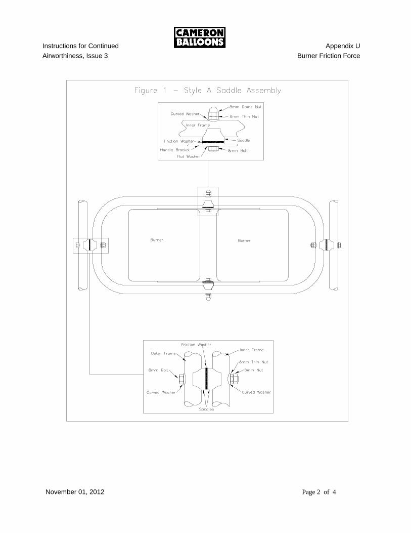
Instructions for Continued Appendix U
Airworthiness, Issue 3 Burner Friction Force
November 01, 2012 Page 2 of 4
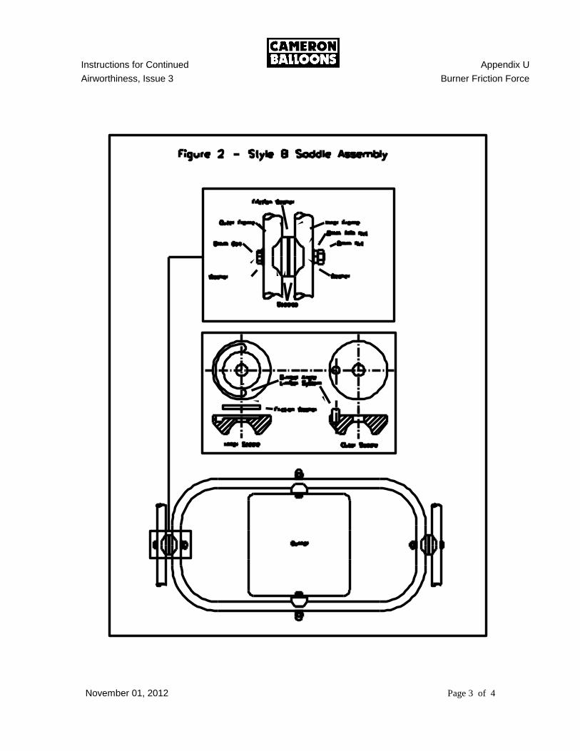
Instructions for Continued Appendix U
Airworthiness, Issue 3 Burner Friction Force
November 01, 2012 Page 3 of 4
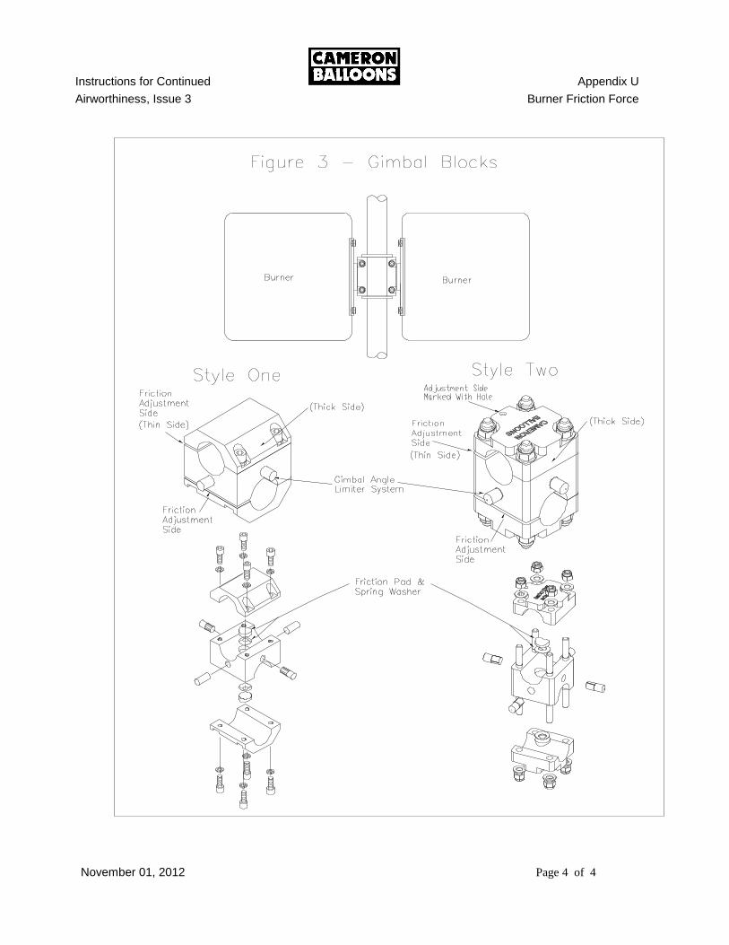
Instructions for Continued Appendix U
Airworthiness, Issue 3 Burner Friction Force
November 01, 2012 Page 4 of 4
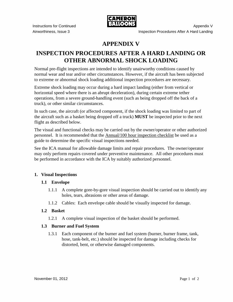
Instructions for Continued Appendix V
Airworthiness, Issue 3 Inspection Procedures After A Hard Landing
November 01, 2012 Page 1 of 2
APPENDIX V
INSPECTION PROCEDURES AFTER A HARD LANDING OR
OTHER ABNORMAL SHOCK LOADING
Normal pre-flight inspections are intended to identify unairworthy conditions caused by
normal wear and tear and/or other circumstances. However, if the aircraft has been subjected
to extreme or abnormal shock loading additional inspection procedures are necessary.
Extreme shock loading may occur during a hard impact landing (either from vertical or
horizontal speed where there is an abrupt deceleration), during certain extreme tether
operations, from a severe ground-handling event (such as being dropped off the back of a
truck), or other similar circumstances.
In such case, the aircraft (or affected component, if the shock loading was limited to part of
the aircraft such as a basket being dropped off a truck) MUST be inspected prior to the next
flight as described below.
The visual and functional checks may be carried out by the owner/operator or other authorized
personnel. It is recommended that the Annual/100 hour inspection checklist be used as a
guide to determine the specific visual inspections needed.
See the ICA manual for allowable damage limits and repair procedures. The owner/operator
may only perform repairs covered under preventive maintenance. All other procedures must
be performed in accordance with the ICA by suitably authorized personnel.
1. Visual Inspections
1.1 Envelope
1.1.1 A complete gore-by-gore visual inspection should be carried out to identify any
holes, tears, abrasions or other areas of damage.
1.1.2 Cables: Each envelope cable should be visually inspected for damage.
1.2 Basket
1.2.1 A complete visual inspection of the basket should be performed.
1.3 Burner and Fuel System
1.3.1 Each component of the burner and fuel system (burner, burner frame, tank,
hose, tank-belt, etc.) should be inspected for damage including checks for
distorted, bent, or otherwise damaged components.

Instructions for Continued Appendix V
Airworthiness, Issue 3 Inspection Procedures After A Hard Landing
November 01, 2012 Page 2 of 2
2. Functional Checks
2.1 Burner and Fuel System
2.1.1 A complete functional check of the burner and fuel system must be
carried out. As a minimum each burner should be checked for leaks and
proper operation (including each valve – main blast valve, whisper valve,
pilot light valve, and cross-flow valve). Each tank should be checked for
leaks and proper operation, to ensure that each tank will deliver fuel to
the burner in the normal manner.
2.2 Instruments
2.2.1 A functional check of the instruments should be made to ensure that they
show proper altitude and register climbs and descents when moved
abruptly.
3. Log Book Entries
3.1 Completion of the inspection should be entered in the aircraft’s log book.
3.2 Any maintenance that was performed as a result of the inspection must be
documented in the aircraft log book and the aircraft returned to service by an
appropriately authorized person.
Note:
A cylinder that leaks, is bulged, dented, has defective valves or safety devices, fire or
heat damage, rust or corrosion MUST NOT be put into service UNTIL it has been
inspected and properly repaired by a certified repair person.
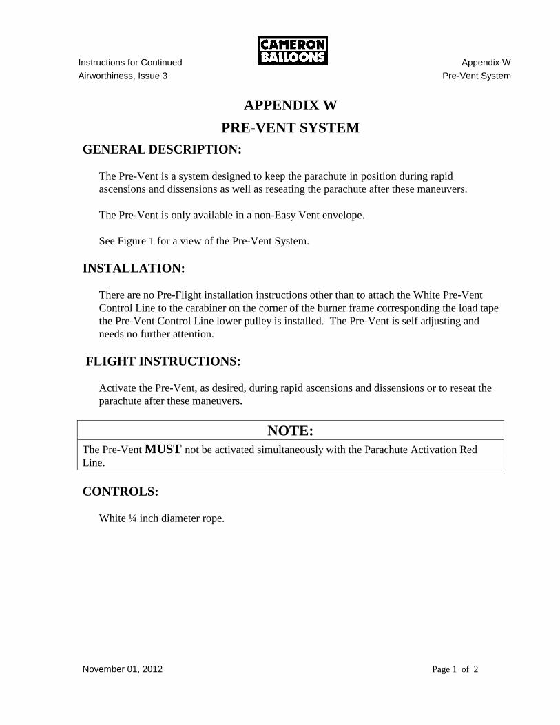
Instructions for Continued Appendix W
Airworthiness, Issue 3 Pre-Vent System
November 01, 2012 Page 1 of 2
APPENDIX W
PRE-VENT SYSTEM
GENERAL DESCRIPTION:
The Pre-Vent is a system designed to keep the parachute in position during rapid
ascensions and dissensions as well as reseating the parachute after these maneuvers.
The Pre-Vent is only available in a non-Easy Vent envelope.
See Figure 1 for a view of the Pre-Vent System.
INSTALLATION:
There are no Pre-Flight installation instructions other than to attach the White Pre-Vent
Control Line to the carabiner on the corner of the burner frame corresponding the load tape
the Pre-Vent Control Line lower pulley is installed. The Pre-Vent is self adjusting and
needs no further attention.
FLIGHT INSTRUCTIONS:
Activate the Pre-Vent, as desired, during rapid ascensions and dissensions or to reseat the
parachute after these maneuvers.
NOTE:
The Pre-Vent MUST not be activated simultaneously with the Parachute Activation Red
Line.
CONTROLS:
White ¼ inch diameter rope.
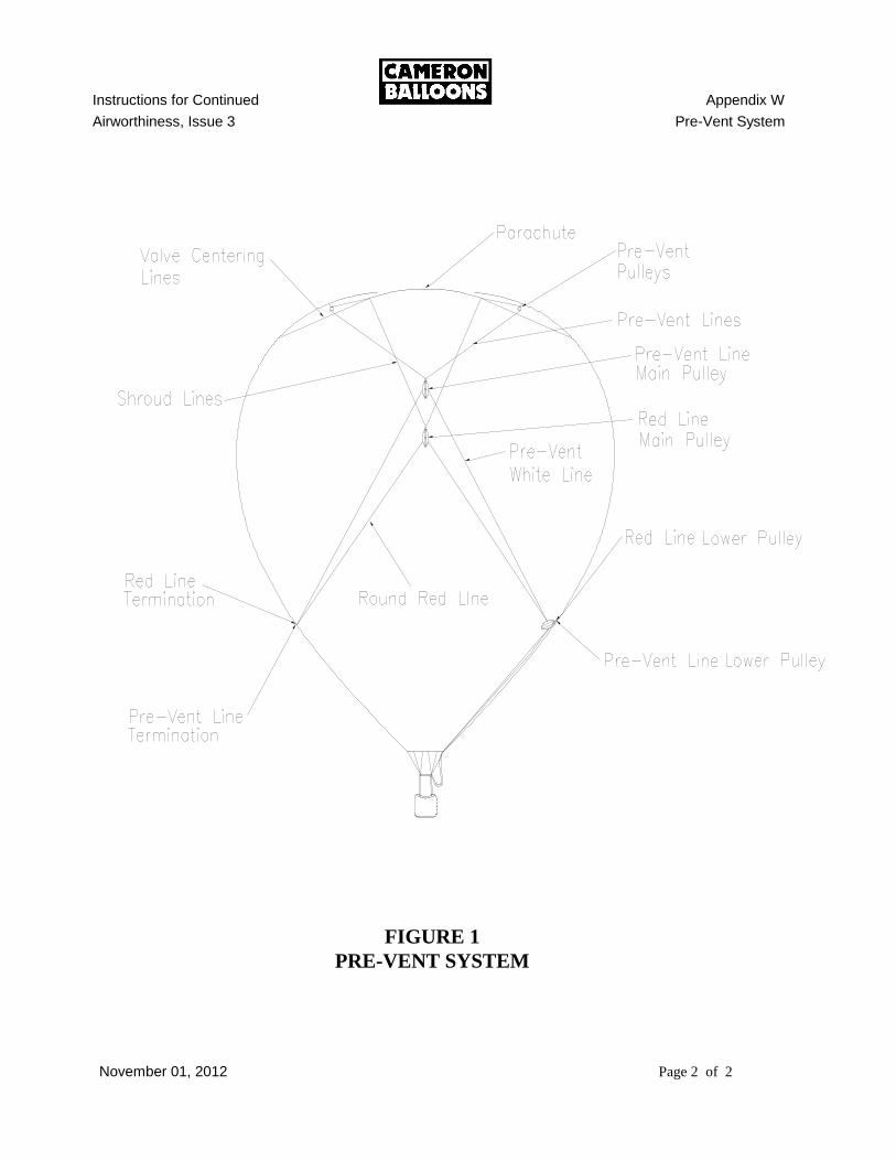
Instructions for Continued Appendix W
Airworthiness, Issue 3 Pre-Vent System
November 01, 2012 Page 2 of 2
FIGURE 1
PRE-VENT SYSTEM
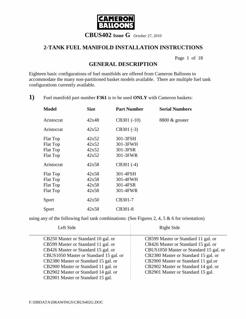
CBUS402 Issue G October 27, 2010
2-TANK FUEL MANIFOLD INSTALLATION INSTRUCTIONS
Page 1 of 18
F:\DBDATA\DRAWINGS\CBUS402G.DOC
GENERAL DESCRIPTION
Eighteen basic configurations of fuel manifolds are offered from Cameron Balloons to
accommodate the many non-partitioned basket models available. There are multiple fuel tank
configurations currently available.
1) Fuel manifold part number F361 is to be used ONLY with Cameron baskets:
Model Size Part Number Serial Numbers
Aristocrat 42x48 CB301 (-10) 8800 & greater
Aristocrat 42x52 CB301 (-3)
Flat Top 42x52 301-3FSH
Flat Top 42x52 301-3FWH
Flat Top 42x52 301-3FSR
Flat Top 42x52 301-3FWR
Aristocrat 42x58 CB301 (-4)
Flat Top 42x58 301-4FSH
Flat Top 42x58 301-4FWH
Flat Top 42x58 301-4FSR
Flat Top 42x58 301-4FWR
Sport 42x50 CB301-7
Sport 42x58 CB301-8
using any of the following fuel tank combinations: (See Figures 2, 4, 5 & 6 for orientation)
Left Side Right Side
__________________________________________________________________________________
CB250 Master or Standard 10 gal. or CB599 Master or Standard 11 gal. or
CB599 Master or Standard 11 gal. or CB426 Master or Standard 15 gal. or
CB426 Master or Standard 15 gal. or CBUS1050 Master or Standard 15 gal. or
CBUS1050 Master or Standard 15 gal. or CB2380 Master or Standard 15 gal. or
CB2380 Master or Standard 15 gal. or CB2900 Master or Standard 11 gal.or
CB2900 Master or Standard 11 gal. or CB2902 Master or Standard 14 gal. or
CB2902 Master or Standard 14 gal. or CB2901 Master or Standard 15 gal.
CB2901 Master or Standard 15 gal.

CBUS402 Issue G October 27, 2010
2-TANK FUEL MANIFOLD INSTALLATION INSTRUCTIONS
Page 2 of 18
F:\DBDATA\DRAWINGS\CBUS402G.DOC
2) Fuel manifold part number F362 is to be used ONLY with Cameron baskets:
Model Size Part Number Serial Number
Aristocrat 42x48 CB301 (-10) All numbers for
AL to AL
Aristocrat 42x52 CB301 (-3)
8800 & greater for
Flat Top 42x52 301-3FSH SS/TI to AL
Flat Top 42x52 301-3FWH
Flat Top 42x52 301-3FSR
Flat Top 42x52 301-3FWR
Aristocrat 42x58 CB301 (-4)
Flat Top 42x58 301-4FSR
Flat Top 42x58 301-4FWR
Flat Top 42x58 301-4FSR
Flat Top 42x58 301-4FWR
Sport 42x50 CB301-7
Sport 42x58 CB301-8
using any of the following fuel tank combinations: (See Figures 1 & 3 for orientation)
Left Side Right Side
__________________________________________________________________________________
CB250 Master or Standard 10 gal. CB250 Standard 10 gal. ONLY
CB599 Master or Standard 11 gal. or
CB426 Master or Standard 15 gal. or
CBUS1050 Master or Standard 15 gal. or
CB2380 Master or Standard 15 gal.
CB2900 Master or Standard 11 gal. or
CB2902 Master or Standard 14 gal. or
CB2901 Master or Standard 15 gal.
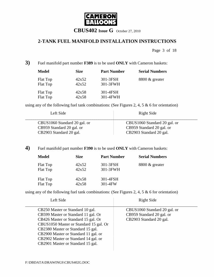
CBUS402 Issue G October 27, 2010
2-TANK FUEL MANIFOLD INSTALLATION INSTRUCTIONS
Page 3 of 18
F:\DBDATA\DRAWINGS\CBUS402G.DOC
3) Fuel manifold part number F389 is to be used ONLY with Cameron baskets:
Model Size Part Number Serial Numbers
Flat Top 42x52 301-3FSH 8800 & greater
Flat Top 42x52 301-3FWH
Flat Top 42x58 301-4FSH
Flat Top 42x58 301-4FWH
using any of the following fuel tank combinations: (See Figures 2, 4, 5 & 6 for orientation)
Left Side Right Side
__________________________________________________________________________________
CBUS1060 Standard 20 gal. or CBUS1060 Standard 20 gal. or
CB959 Standard 20 gal. or CB959 Standard 20 gal. or
CB2903 Standard 20 gal. CB2903 Standard 20 gal.
4) Fuel manifold part number F390 is to be used ONLY with Cameron baskets:
Model Size Part Number Serial Numbers
Flat Top 42x52 301-3FSH 8800 & greater
Flat Top 42x52 301-3FWH
Flat Top 42x58 301-4FSH
Flat Top 42x58 301-4FW
using any of the following fuel tank combinations: (See Figures 2, 4, 5 & 6 for orientation)
Left Side Right Side
__________________________________________________________________________________
CB250 Master or Standard 10 gal. CBUS1060 Standard 20 gal. or
CB599 Master or Standard 11 gal. Or CB959 Standard 20 gal. or
CB426 Master or Standard 15 gal. Or CB2903 Standard 20 gal.
CBUS1050 Master or Standard 15 gal. Or
CB2380 Master or Standard 15 gal.
CB2900 Master or Standard 11 gal. or
CB2902 Master or Standard 14 gal. or
CB2901 Master or Standard 15 gal.
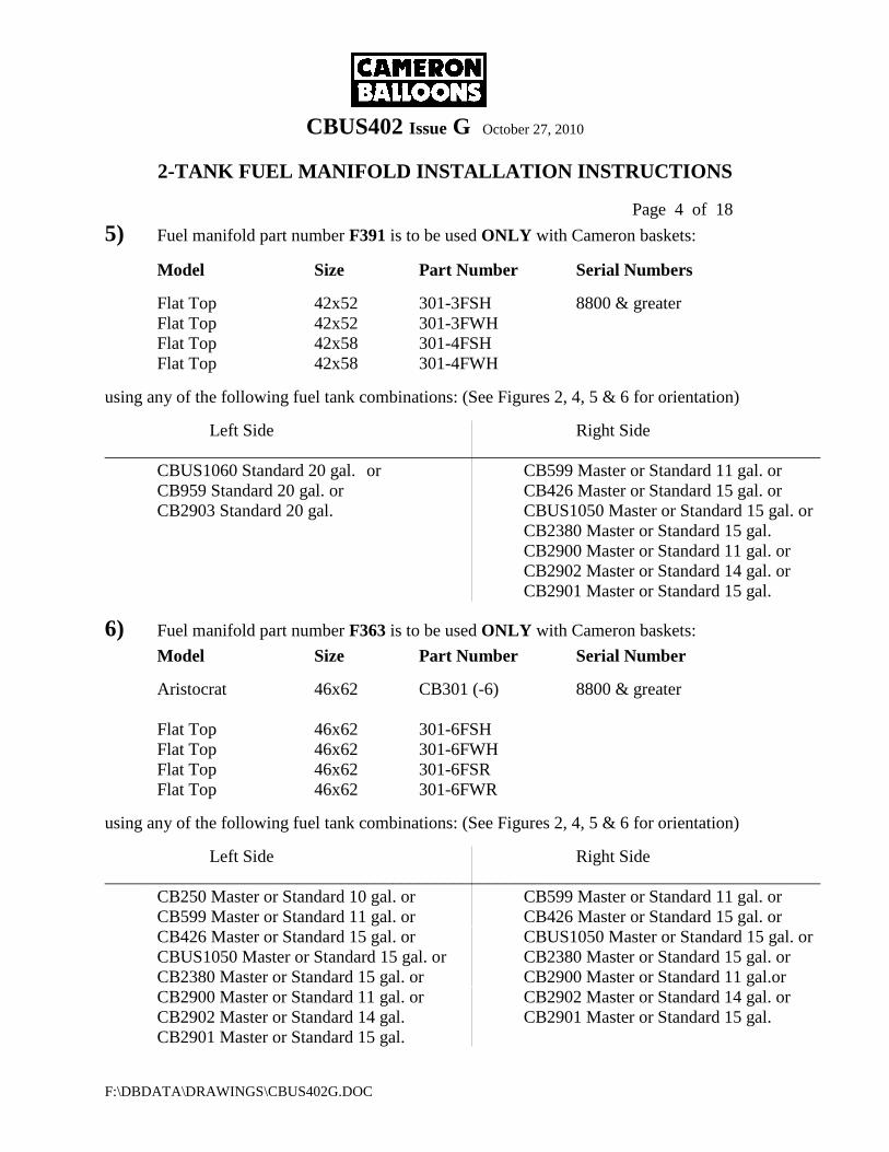
CBUS402 Issue G October 27, 2010
2-TANK FUEL MANIFOLD INSTALLATION INSTRUCTIONS
Page 4 of 18
F:\DBDATA\DRAWINGS\CBUS402G.DOC
5) Fuel manifold part number F391 is to be used ONLY with Cameron baskets:
Model Size Part Number Serial Numbers
Flat Top 42x52 301-3FSH 8800 & greater
Flat Top 42x52 301-3FWH
Flat Top 42x58 301-4FSH
Flat Top 42x58 301-4FWH
using any of the following fuel tank combinations: (See Figures 2, 4, 5 & 6 for orientation)
Left Side Right Side
__________________________________________________________________________________
CBUS1060 Standard 20 gal. or CB599 Master or Standard 11 gal. or
CB959 Standard 20 gal. or CB426 Master or Standard 15 gal. or
CB2903 Standard 20 gal. CBUS1050 Master or Standard 15 gal. or
CB2380 Master or Standard 15 gal.
CB2900 Master or Standard 11 gal. or
CB2902 Master or Standard 14 gal. or
CB2901 Master or Standard 15 gal.
6) Fuel manifold part number F363 is to be used ONLY with Cameron baskets:
Model Size Part Number Serial Number
Aristocrat 46x62 CB301 (-6) 8800 & greater
Flat Top 46x62 301-6FSH
Flat Top 46x62 301-6FWH
Flat Top 46x62 301-6FSR
Flat Top 46x62 301-6FWR
using any of the following fuel tank combinations: (See Figures 2, 4, 5 & 6 for orientation)
Left Side Right Side
__________________________________________________________________________________
CB250 Master or Standard 10 gal. or CB599 Master or Standard 11 gal. or
CB599 Master or Standard 11 gal. or CB426 Master or Standard 15 gal. or
CB426 Master or Standard 15 gal. or CBUS1050 Master or Standard 15 gal. or
CBUS1050 Master or Standard 15 gal. or CB2380 Master or Standard 15 gal. or
CB2380 Master or Standard 15 gal. or CB2900 Master or Standard 11 gal.or
CB2900 Master or Standard 11 gal. or CB2902 Master or Standard 14 gal. or
CB2902 Master or Standard 14 gal. CB2901 Master or Standard 15 gal.
CB2901 Master or Standard 15 gal.
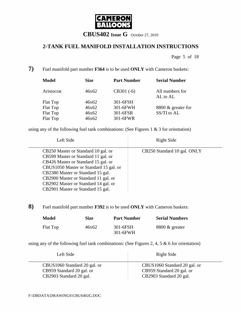
CBUS402 Issue G October 27, 2010
2-TANK FUEL MANIFOLD INSTALLATION INSTRUCTIONS
Page 5 of 18
F:\DBDATA\DRAWINGS\CBUS402G.DOC
7) Fuel manifold part number F364 is to be used ONLY with Cameron baskets:
Model Size Part Number Serial Number
Aristocrat 46x62 CB301 (-6) All numbers for
AL to AL
Flat Top 46x62 301-6FSH
Flat Top 46x62 301-6FWH 8800 & greater for
Flat Top 46x62 301-6FSR SS/TI to AL
Flat Top 46x62 301-6FWR
using any of the following fuel tank combinations: (See Figures 1 & 3 for orientation)
Left Side Right Side
__________________________________________________________________________________
CB250 Master or Standard 10 gal. or CB250 Standard 10 gal. ONLY
CB599 Master or Standard 11 gal. or
CB426 Master or Standard 15 gal. or
CBUS1050 Master or Standard 15 gal. or
CB2380 Master or Standard 15 gal.
CB2900 Master or Standard 11 gal. or
CB2902 Master or Standard 14 gal. or
CB2901 Master or Standard 15 gal.
8) Fuel manifold part number F392 is to be used ONLY with Cameron baskets:
Model Size Part Number Serial Numbers
Flat Top 46x62 301-6FSH 8800 & greater
301-6FWH
using any of the following fuel tank combinations: (See Figures 2, 4, 5 & 6 for orientation)
Left Side Right Side
__________________________________________________________________________________
CBUS1060 Standard 20 gal. or CBUS1060 Standard 20 gal. or
CB959 Standard 20 gal. or CB959 Standard 20 gal. or
CB2903 Standard 20 gal. CB2903 Standard 20 gal.

CBUS402 Issue G October 27, 2010
2-TANK FUEL MANIFOLD INSTALLATION INSTRUCTIONS
Page 6 of 18
F:\DBDATA\DRAWINGS\CBUS402G.DOC
9) Fuel manifold part number F393 is to be used ONLY with Cameron baskets:
Model Size Part Number Serial Numbers
Aristocrat 46x62 301-6FSH 8800 & greater
301-6FWH
using any of the following fuel tank combinations: (See Figures 2, 4, 5 & 6 for orientation)
Left Side Right Side
__________________________________________________________________________________
CB599 Master or Standard 11 gal. Or CBUS1060 Standard 20 gal. or
CB426 Master or Standard 15 gal. Or CB959 Standard 20 gal. or
CBUS1050 Master or Standard 15 gal. Or CB2903 Standard 20 gal.
CB2380 Master or Standard 15 gal.
CB2900 Master or Standard 11 gal. or
CB2902 Master or Standard 14 gal. or
CB2901 Master or Standard 15 gal.
10) Fuel manifold part number F394 is to be used ONLY with Cameron baskets:
Model Size Part Number Serial Numbers
Aristocrat 46x62 301-6FSH 8800 & greater
301-6FWH
using any of the following fuel tank combinations: (See Figures 2, 4, 5 & 6 for orientation)
Left Side Right Side
__________________________________________________________________________________
CBUS1060 Standard 20 gal. or CB599 Master or Standard 11 gal. or
CB959 Standard 20 gal. or CB426 Master or Standard 15 gal. or
CB2903 Standard 20 gal. CBUS1050 Master or Standard 15 gal. or
CB2380 Master or Standard 15 gal.
CB2900 Master or Standard 11 gal. or
CB2902 Master or Standard 14 gal. or
CB2901 Master or Standard 15 gal.
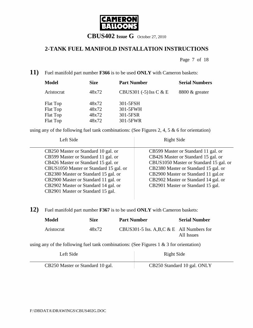
CBUS402 Issue G October 27, 2010
2-TANK FUEL MANIFOLD INSTALLATION INSTRUCTIONS
Page 7 of 18
F:\DBDATA\DRAWINGS\CBUS402G.DOC
11) Fuel manifold part number F366 is to be used ONLY with Cameron baskets:
Model Size Part Number Serial Numbers
Aristocrat 48x72 CBUS301 (-5) Iss C & E 8800 & greater
Flat Top 48x72 301-5FSH
Flat Top 48x72 301-5FWH
Flat Top 48x72 301-5FSR
Flat Top 48x72 301-5FWR
using any of the following fuel tank combinations: (See Figures 2, 4, 5 & 6 for orientation)
Left Side Right Side
__________________________________________________________________________________
CB250 Master or Standard 10 gal. or CB599 Master or Standard 11 gal. or
CB599 Master or Standard 11 gal. or CB426 Master or Standard 15 gal. or
CB426 Master or Standard 15 gal. or CBUS1050 Master or Standard 15 gal. or
CBUS1050 Master or Standard 15 gal. or CB2380 Master or Standard 15 gal. or
CB2380 Master or Standard 15 gal. or CB2900 Master or Standard 11 gal.or
CB2900 Master or Standard 11 gal. or CB2902 Master or Standard 14 gal. or
CB2902 Master or Standard 14 gal. or CB2901 Master or Standard 15 gal.
CB2901 Master or Standard 15 gal.
12) Fuel manifold part number F367 is to be used ONLY with Cameron baskets:
Model Size Part Number Serial Number
Aristocrat 48x72 CBUS301-5 Iss. A,B,C & E All Numbers for
All Issues
using any of the following fuel tank combinations: (See Figures 1 & 3 for orientation)
Left Side Right Side
__________________________________________________________________________________
CB250 Master or Standard 10 gal. CB250 Standard 10 gal. ONLY
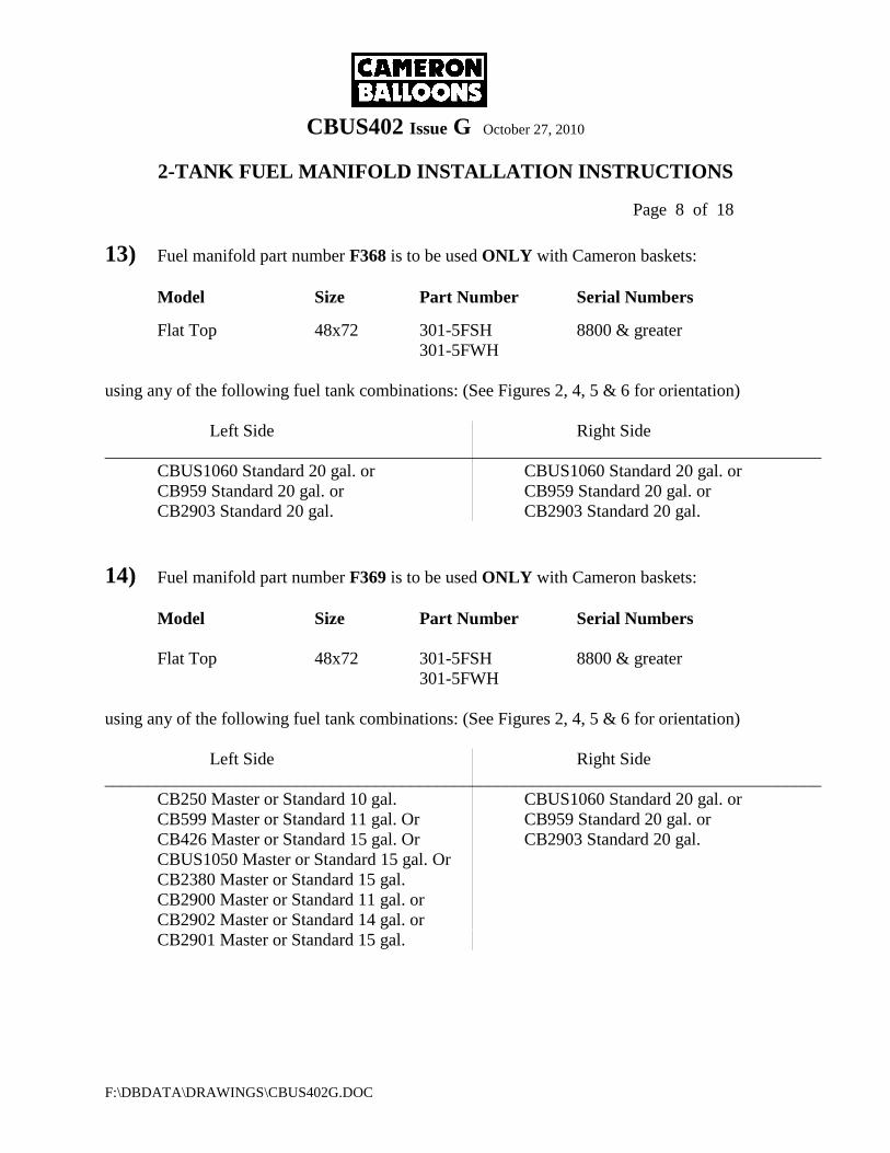
CBUS402 Issue G October 27, 2010
2-TANK FUEL MANIFOLD INSTALLATION INSTRUCTIONS
Page 8 of 18
F:\DBDATA\DRAWINGS\CBUS402G.DOC
13) Fuel manifold part number F368 is to be used ONLY with Cameron baskets:
Model Size Part Number Serial Numbers
Flat Top 48x72 301-5FSH 8800 & greater
301-5FWH
using any of the following fuel tank combinations: (See Figures 2, 4, 5 & 6 for orientation)
Left Side Right Side
__________________________________________________________________________________
CBUS1060 Standard 20 gal. or CBUS1060 Standard 20 gal. or
CB959 Standard 20 gal. or CB959 Standard 20 gal. or
CB2903 Standard 20 gal. CB2903 Standard 20 gal.
14) Fuel manifold part number F369 is to be used ONLY with Cameron baskets:
Model Size Part Number Serial Numbers
Flat Top 48x72 301-5FSH 8800 & greater
301-5FWH
using any of the following fuel tank combinations: (See Figures 2, 4, 5 & 6 for orientation)
Left Side Right Side
__________________________________________________________________________________
CB250 Master or Standard 10 gal. CBUS1060 Standard 20 gal. or
CB599 Master or Standard 11 gal. Or CB959 Standard 20 gal. or
CB426 Master or Standard 15 gal. Or CB2903 Standard 20 gal.
CBUS1050 Master or Standard 15 gal. Or
CB2380 Master or Standard 15 gal.
CB2900 Master or Standard 11 gal. or
CB2902 Master or Standard 14 gal. or
CB2901 Master or Standard 15 gal.
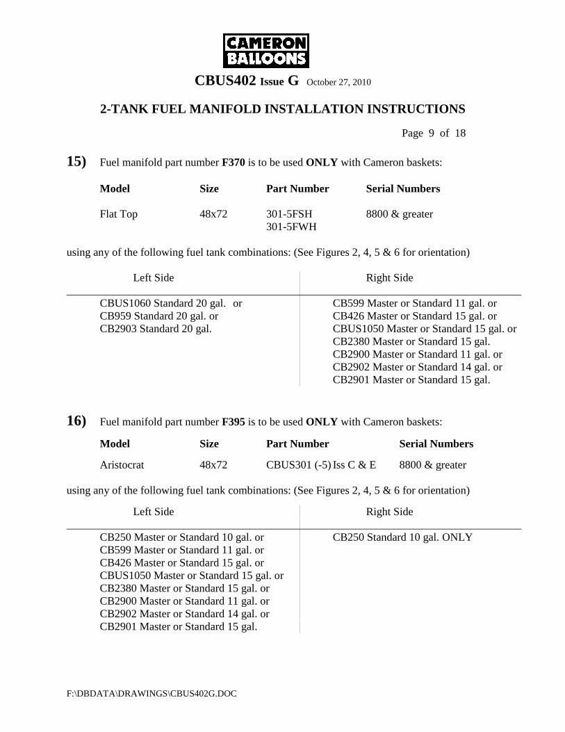
CBUS402 Issue G October 27, 2010
2-TANK FUEL MANIFOLD INSTALLATION INSTRUCTIONS
Page 9 of 18
F:\DBDATA\DRAWINGS\CBUS402G.DOC
15) Fuel manifold part number F370 is to be used ONLY with Cameron baskets:
Model Size Part Number Serial Numbers
Flat Top 48x72 301-5FSH 8800 & greater
301-5FWH
using any of the following fuel tank combinations: (See Figures 2, 4, 5 & 6 for orientation)
Left Side Right Side
__________________________________________________________________________________
CBUS1060 Standard 20 gal. or CB599 Master or Standard 11 gal. or
CB959 Standard 20 gal. or CB426 Master or Standard 15 gal. or
CB2903 Standard 20 gal. CBUS1050 Master or Standard 15 gal. or
CB2380 Master or Standard 15 gal.
CB2900 Master or Standard 11 gal. or
CB2902 Master or Standard 14 gal. or
CB2901 Master or Standard 15 gal.
16) Fuel manifold part number F395 is to be used ONLY with Cameron baskets:
Model Size Part Number Serial Numbers
Aristocrat 48x72 CBUS301 (-5) Iss C & E 8800 & greater
using any of the following fuel tank combinations: (See Figures 2, 4, 5 & 6 for orientation)
Left Side Right Side
__________________________________________________________________________________
CB250 Master or Standard 10 gal. or CB250 Standard 10 gal. ONLY
CB599 Master or Standard 11 gal. or
CB426 Master or Standard 15 gal. or
CBUS1050 Master or Standard 15 gal. or
CB2380 Master or Standard 15 gal. or
CB2900 Master or Standard 11 gal. or
CB2902 Master or Standard 14 gal. or
CB2901 Master or Standard 15 gal.
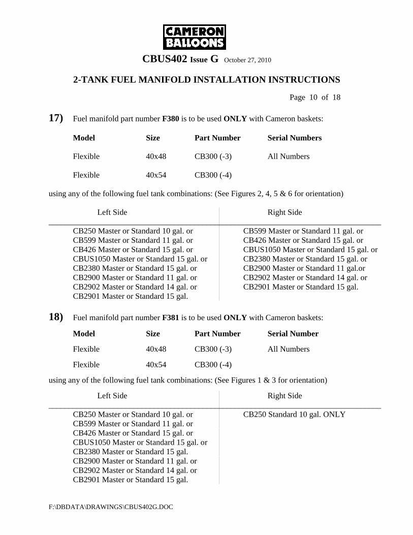
CBUS402 Issue G October 27, 2010
2-TANK FUEL MANIFOLD INSTALLATION INSTRUCTIONS
Page 10 of 18
F:\DBDATA\DRAWINGS\CBUS402G.DOC
17) Fuel manifold part number F380 is to be used ONLY with Cameron baskets:
Model Size Part Number Serial Numbers
Flexible 40x48 CB300 (-3) All Numbers
Flexible 40x54 CB300 (-4)
using any of the following fuel tank combinations: (See Figures 2, 4, 5 & 6 for orientation)
Left Side Right Side
__________________________________________________________________________________
CB250 Master or Standard 10 gal. or CB599 Master or Standard 11 gal. or
CB599 Master or Standard 11 gal. or CB426 Master or Standard 15 gal. or
CB426 Master or Standard 15 gal. or CBUS1050 Master or Standard 15 gal. or
CBUS1050 Master or Standard 15 gal. or CB2380 Master or Standard 15 gal. or
CB2380 Master or Standard 15 gal. or CB2900 Master or Standard 11 gal.or
CB2900 Master or Standard 11 gal. or CB2902 Master or Standard 14 gal. or
CB2902 Master or Standard 14 gal. or CB2901 Master or Standard 15 gal.
CB2901 Master or Standard 15 gal.
18) Fuel manifold part number F381 is to be used ONLY with Cameron baskets:
Model Size Part Number Serial Number
Flexible 40x48 CB300 (-3) All Numbers
Flexible 40x54 CB300 (-4)
using any of the following fuel tank combinations: (See Figures 1 & 3 for orientation)
Left Side Right Side
__________________________________________________________________________________
CB250 Master or Standard 10 gal. or CB250 Standard 10 gal. ONLY
CB599 Master or Standard 11 gal. or
CB426 Master or Standard 15 gal. or
CBUS1050 Master or Standard 15 gal. or
CB2380 Master or Standard 15 gal.
CB2900 Master or Standard 11 gal. or
CB2902 Master or Standard 14 gal. or
CB2901 Master or Standard 15 gal.

CBUS402 Issue G October 27, 2010
2-TANK FUEL MANIFOLD INSTALLATION INSTRUCTIONS
Page 11 of 18
F:\DBDATA\DRAWINGS\CBUS402G.DOC
The manifolds listed on the previous pages are designed to be used without burner hose
modification. Once installed in the basket, these manifolds may or may not be connected into
the fuel system of the balloon for a particular flight. However, BOTH manifold hoses MUST be
connected OR, BOTH manifold hoses MUST be disconnected.
NOTE:
IT IS NOT PERMISSIBLE TO OPERATE THE AIRCRAFT WITH ONLY ONE
MANIFOLD HOSE CONNECTED TO THE FUEL SYSTEM.
INSTALLATION OVERVIEW
Installation of the manifold into the basket MUST be done by an FAA certified repair person.
Proper logbook entries must be made.
Proper installation is important to prevent failure of the manifold if the system is exposed to high
impact forces. Proper installation is also important to prevent damage to the manifold in flight,
ground handling and transport.
The manifold(s) MUST be installed according to these instructions. The manifold MUST be
positioned in the basket to prevent stress from ever being placed on the hoses and to prevent the
hoses from being pinched or rubbed by the tank collars, basket walls or any other part.
The hardwood spacing block and nylon cable ties are integral to the proper function of the
manifold. They MUST be used and no other parts may be substituted for them. One of the
functions they perform is to provide a degree of electrical insulation to help prevent electrical
damage to the fuel system. Another function is to intentionally provide a mechanically weak
point in the manifold mounting system. This weak point will help prevent damage to the fuel
hoses due to basket distortion, which results from high impact forces.
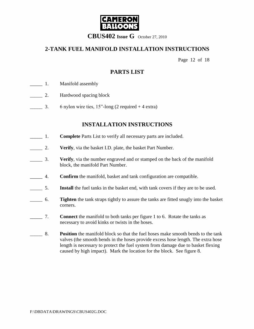
CBUS402 Issue G October 27, 2010
2-TANK FUEL MANIFOLD INSTALLATION INSTRUCTIONS
Page 12 of 18
F:\DBDATA\DRAWINGS\CBUS402G.DOC
PARTS LIST
_____ 1. Manifold assembly
_____ 2. Hardwood spacing block
_____ 3. 6 nylon wire ties, 15”-long (2 required + 4 extra)
INSTALLATION INSTRUCTIONS
_____ 1. Complete Parts List to verify all necessary parts are included.
_____ 2. Verify, via the basket I.D. plate, the basket Part Number.
_____ 3. Verify, via the number engraved and or stamped on the back of the manifold
block, the manifold Part Number.
_____ 4. Confirm the manifold, basket and tank configuration are compatible.
_____ 5. Install the fuel tanks in the basket end, with tank covers if they are to be used.
_____ 6. Tighten the tank straps tightly to assure the tanks are fitted snugly into the basket
corners.
_____ 7. Connect the manifold to both tanks per figure 1 to 6. Rotate the tanks as
necessary to avoid kinks or twists in the hoses.
_____ 8. Position the manifold block so that the fuel hoses make smooth bends to the tank
valves (the smooth bends in the hoses provide excess hose length. The extra hose
length is necessary to protect the fuel system from damage due to basket flexing
caused by high impact). Mark the location for the block. See figure 8.
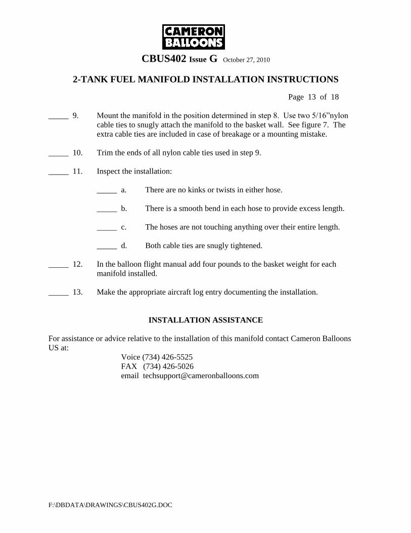
CBUS402 Issue G October 27, 2010
2-TANK FUEL MANIFOLD INSTALLATION INSTRUCTIONS
Page 13 of 18
F:\DBDATA\DRAWINGS\CBUS402G.DOC
_____ 9. Mount the manifold in the position determined in step 8. Use two 5/16”nylon
cable ties to snugly attach the manifold to the basket wall. See figure 7. The
extra cable ties are included in case of breakage or a mounting mistake.
_____ 10. Trim the ends of all nylon cable ties used in step 9.
_____ 11. Inspect the installation:
_____ a. There are no kinks or twists in either hose.
_____ b. There is a smooth bend in each hose to provide excess length.
_____ c. The hoses are not touching anything over their entire length.
_____ d. Both cable ties are snugly tightened.
_____ 12. In the balloon flight manual add four pounds to the basket weight for each
manifold installed.
_____ 13. Make the appropriate aircraft log entry documenting the installation.
INSTALLATION ASSISTANCE
For assistance or advice relative to the installation of this manifold contact Cameron Balloons
US at:
Voice (734) 426-5525
FAX (734) 426-5026
email [email protected]
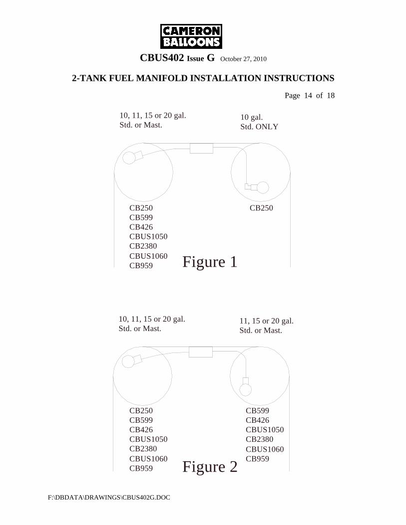
CBUS402 Issue G October 27, 2010
2-TANK FUEL MANIFOLD INSTALLATION INSTRUCTIONS
Page 14 of 18
F:\DBDATA\DRAWINGS\CBUS402G.DOC
10, 11, 15 or 20 gal.
Std. or Mast.10 gal.
Std. ONLY
Std. or Mast.
11, 15 or 20 gal.Std. or Mast.
10, 11, 15 or 20 gal.
Figure 2
Figure 1
CB250
CB599
CB426
CBUS1050
CB2380
CB250
CBUS1060
CB959
CB250
CB599
CB426
CBUS1050
CB2380
CBUS1060
CB959
CB599
CB426
CBUS1050
CB2380
CBUS1060
CB959
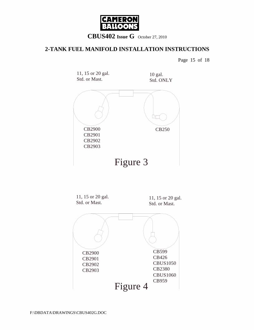
CBUS402 Issue G October 27, 2010
2-TANK FUEL MANIFOLD INSTALLATION INSTRUCTIONS
Page 15 of 18
F:\DBDATA\DRAWINGS\CBUS402G.DOC
Figure 3
CB250CB2900
CB2901
CB2902
CB2903
CB2900
CB2901
CB2902
CB2903
CB599
CB426
CBUS1050
CB2380
CBUS1060
CB959
11, 15 or 20 gal.
Std. or Mast.10 gal.
Std. ONLY
Std. or Mast.
11, 15 or 20 gal.Std. or Mast.
11, 15 or 20 gal.
Figure 4
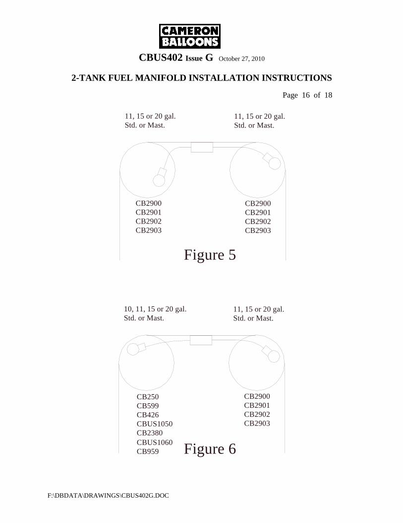
CBUS402 Issue G October 27, 2010
2-TANK FUEL MANIFOLD INSTALLATION INSTRUCTIONS
Page 16 of 18
F:\DBDATA\DRAWINGS\CBUS402G.DOC
11, 15 or 20 gal.
Std. or Mast.
CB2900
CB2901
CB2902
CB2903
11, 15 or 20 gal.
Std. or Mast.
CB2900
CB2901
CB2902
CB2903
CB250
CB599
CB426
CBUS1050
CB2380
CBUS1060
CB959
11, 15 or 20 gal.
Std. or Mast.
Std. or Mast.
10, 11, 15 or 20 gal.
Figure 6
Figure 5
CB2900
CB2901
CB2902
CB2903
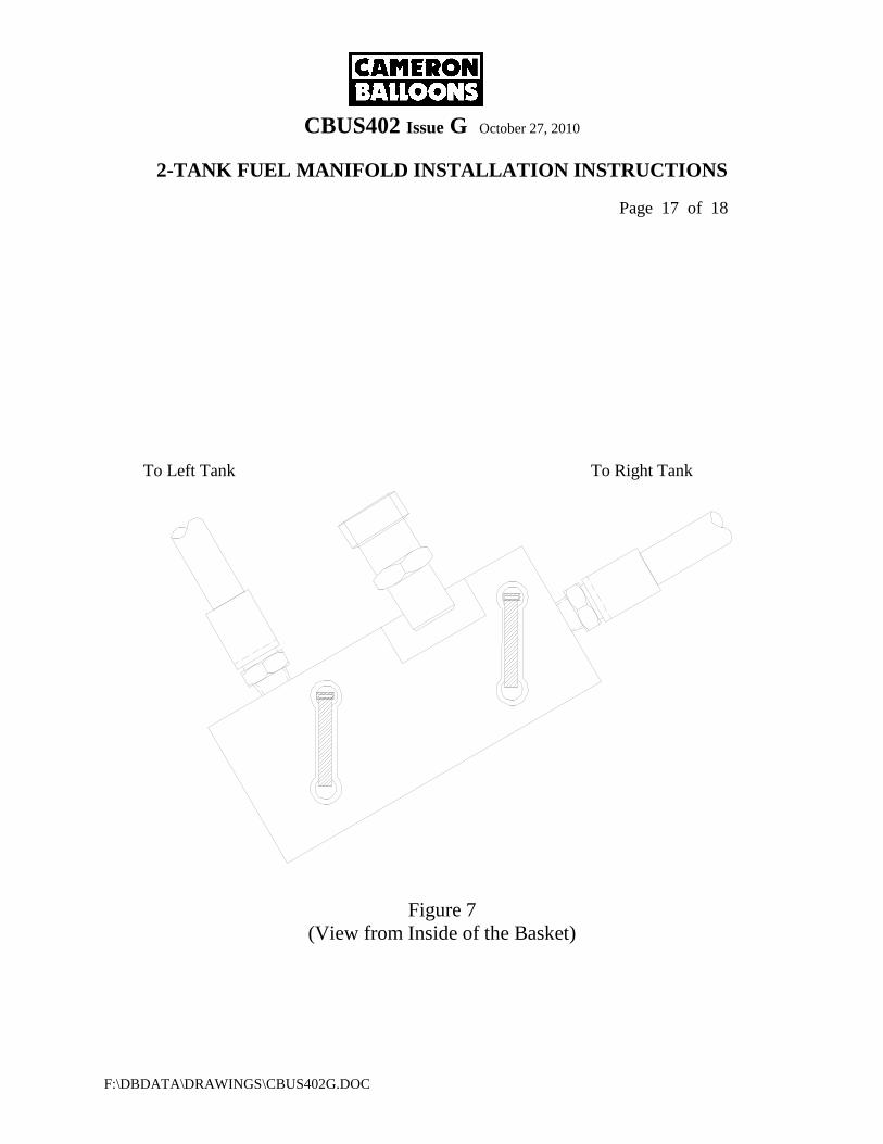
CBUS402 Issue G October 27, 2010
2-TANK FUEL MANIFOLD INSTALLATION INSTRUCTIONS
Page 17 of 18
F:\DBDATA\DRAWINGS\CBUS402G.DOC
To Left Tank To Right Tank
Figure 7
(View from Inside of the Basket)
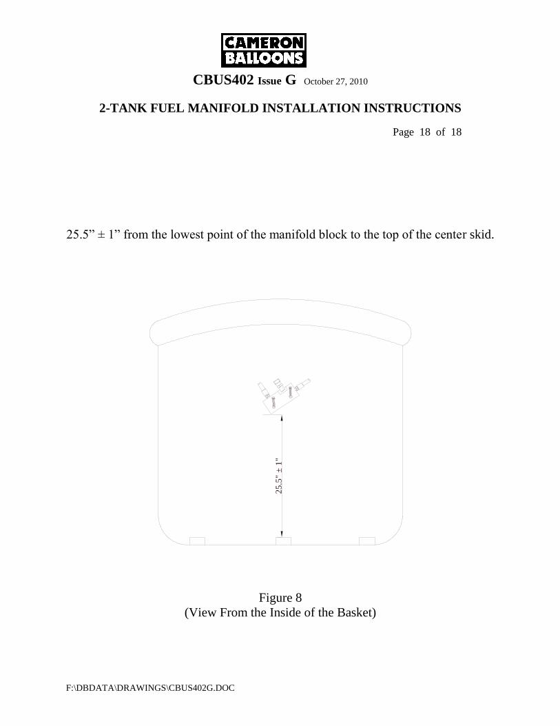
CBUS402 Issue G October 27, 2010
2-TANK FUEL MANIFOLD INSTALLATION INSTRUCTIONS
Page 18 of 18
F:\DBDATA\DRAWINGS\CBUS402G.DOC
25.5” ± 1” from the lowest point of the manifold block to the top of the center skid.
2
5.5
" ±
1"
Figure 8
(View From the Inside of the Basket)

![RELOAD+REFRESH: Abusing Cache Replacement Policies ......In 2010, Jaleel et al. [31] proposed a cache replacement algorithm that makes use of Re-reference Interval Prediction (RRIP)](https://img.pdfslide.us/doc/110x75/60a7c840e2f56f3b2c1a9dd3/reloadrefresh-abusing-cache-replacement-policies-in-2010-jaleel-et-al.jpg)