Embed Size (px)
Citation preview

City of Anaheim– Midway Townhomes Project Appendix N Checklist
FirstCarbon Solutions
Appendix D: Geotechnical Evaluation Report

THIS PAGE INTENTIONALLY LEFT BLANK

1938 Kellogg Avenue, Suite 101, Carlsbad, CA 92008 * Ph: 760-431-3747 www.eeitiger.com
GEOTECHNICAL EVALUATION REPORT
Proposed “Midway Affordable” Housing Development
SWC W. Midway Drive and South Anaheim Boulvard
Anaheim, California
EEI Project NCO-73182.4
April 15, 2021
4/30/2021, 9:50:35 AM
ANAH-OTH2021-01362
Esperanza Rios


TABLE OF CONTENTS
1.0 INTRODUCTION ....................................................................................................................................... 1
1.1 Purpose ....................................................................................................................................... 1
1.2 Project Description ..................................................................................................................... 1
1.3 Scope of Services ........................................................................................................................ 1
2.0 BACKGROUND ......................................................................................................................................... 2
2.1 Subject Property Description ..................................................................................................... 2
2.2 Topography…............ .................................................................................................................. 2
3.0 FIELD EXPLORATION, SUBSURFACE CONDITIONS AND LABORATORY TESTING ................................... 2
3.1 Field Exploration ......................................................................................................................... 2
3.2 Laboratory Testing ...................................................................................................................... 3
4.0 GEOLOGIC SETTING AND SUBSURFACE CONDITIONS ........................................................................... 3
4.1 Geologic Setting .......................................................................................................................... 3
4.2 Site Geology ................................................................................................................................ 4
4.2.1 Alluvium (Qaf)............................................................................................................. 4
4.2.2 Alluvium (Qal) ............................................................................................................. 4
4.3 Groundwater .............................................................................................................................. 4
5.0 GEOLOGIC HAZARDS ............................................................................................................................... 5
5.1 Seismic Design Values ................................................................................................................ 5
Table 1 – ASCE 7-10 Seismic Design Values ..................................................................................... 5
5.2 Faulting and Surface Rupture ..................................................................................................... 5
Table 2 – Nearby Active Faults ......................................................................................................... 6
5.3 Landslides and Slope Stability .................................................................................................... 6
5.4 Liquefaction and Dynamic Settlement ....................................................................................... 6
5.5 Flooding…………. .......................................................................................................................... 6
5.6 Expansive Soil and Subsidence ................................................................................................... 7
6.0 CONCLUSIONS ......................................................................................................................................... 7
7.0 GRADING RECOMMENDATIONS ............................................................................................................ 8
7.1 General ....................................................................................................................................... 8
7.2 Site Preparation and Grading ..................................................................................................... 8
7.3 Remedial Earthwork ................................................................................................................... 9
7.4 Yielding Subgrade Conditions ................................................................................................... 10
7.5 Shrinkage and Bulking .............................................................................................................. 11
7.6 Temporary Site Excavations ..................................................................................................... 11
7.7 Slopes ....................................................................................................................................... 11
8.0 FOUNDATION RECOMMENDATIONS ................................................................................................... 11
8.1 General ..................................................................................................................................... 11
8.2 Shallow Conventional Foundations .......................................................................................... 12
8.3 Footing Setbacks ....................................................................................................................... 12
8.4 Interior Slabs-on-Grade ............................................................................................................ 12
8.5 Exterior Slabs-on-Grade ........................................................................................................... 13
8.6 Pool Design ............................................................................................................................... 14
8.7 Conventional Retaining Walls................................................................................................... 14

TABLE OF CONTENTS (Continued)
8.7.1 Foundations ............................................................................................................... 14
4.2 Lateral Earth Pressure ................................................................................................... 14
8.8 Corrosivity ................................................................................................................................ 15
9.0 PAVEMENT DESIGN RECOMMENDATIONS ......................................................................................... 15
Table 3 – Preliminary Pavement Design Recommendations ......................................................... 16
10.0 DEVELOPMENT RECOMMENDATIONS .............................................................................................. 16
10.1 Landscape Maintenance and Planting ................................................................................... 16
10.2 Site Drainage .......................................................................................................................... 17
10.3 Site Runoff Considertatins – Stormwater Disposal System .................................................... 17
Table 4 – Summary of Percolation Testing..................................................................................... 17
10.4 Structure Setback from Retention Devices ............................................................................ 18
10.5 Additional Site Improvements ................................................................................................ 18
10.6 Utility Trench Backfill .............................................................................................................. 18
11.0 PLAN REVIEW ..................................................................................................................................... 19
12.0 LIMITATIONS ...................................................................................................................................... 19
FIGURES
Figure 1 – Site Vicinity Map
Figure 2 – Aerial Site Map
Figure 3 – Geotechnical Map
APPENDICES
Appendix A – Soil Classification Chart and Boring Logs
Appendix B - Laboratory Test Data
Appendix C- Field Percolation Data
Appendix D – Earthwork and Grading Guidelines
Distribution: (1) Addressee via an electronic copy

Geotechnical Evaluation Report – National Community Renaissance April 15, 2021
Proposed “Midway Affordable” Housing Development, Anaheim, California EEI Project NCO-73182.4
1
1.0 INTRODUCTION
1.1 Purpose
The purpose of this Geotechnical Evaluation Report is to provide geotechnical information to National
Community Renaissance (“Client”) regarding the subject property in the City of Anaheim, County of
Orange, California. The information gathered in this Geotechnical Evaluation is intended to provide the
Client with an understanding of the physical conditions of site-specific subsurface soils, groundwater,
and the regional geologic setting which could affect the cost or design of the proposed development at
the property (Site Vicinity Map-Figure 1, Aerial Site Map-Figure 2).
This Geotechnical Evaluation has been conducted in general accordance with accepted geotechnical
engineering principles as well as in general conformance with the approved proposal and cost estimate
for the project by EEI, dated February 20, 2021.
EEI conducted an onsite field exploration which consisted of the drilling, sampling and logging of six (6)
hollow stem auger exploratory borings and six (6) backhoe test excavation trenches on March 23, 2021
and March 24, 2021, respectively. This Geotechnical Evaluation report has been prepared for the sole
use of National Community Renaissance. Other parties, without the express written consent of EEI and
Cadance Acquisition should not rely upon this Geotechnical Evaluation Report.
1.2 Project Description
Based on our review of the conceptual development plans prepared by ktgy Architectue + Planning
(January 29, 2020), it is our understanding that the proposed development of the subject property will
involve construction of up to four story , 86 units of multi-family residential structures with associated
parking and carport areas, flatworks, utilities, and landscape areas. Construction of a pool and some
ancillary buildings are also planned. No other information regarding the proposed site development is
known at this time.
No detailed grading plans were provided to EEI at the time of our preparation of this report. However,
grading of the subject property is anticipated to include cuts and fills on the order of one to two feet
(exclusive of remedial grading) to provide for site drainage. No foundation plans were provided to EEI at
the time of preparation of this report. However, foundation loads assumed by EEI for the engineering
analysis are up to 4000 pounds per lineal foot and 200 kips for wall and column loads respectively.
1.3 Scope of Services
The scope of our services included:
• A review of the readily available data pertinent to the subject property and immediate vicinity,
including published and unpublished geologic reports/maps and soils data for the area.
• Conducting a geotechnical reconnaissance of the subject property and nearby vicinity.
• Coordination with Underground Service Alert North (USA) to identify the presence of
underground utilities for clearance of the proposed exploratory boring locations.

Geotechnical Evaluation Report – National Community Renaissance April 15, 2021
Proposed “Midway Affordable” Housing Development, Anaheim, California EEI Project NCO-73182.4
2
• Drilling and logging of six (6) hollow stem auger (HSA) (8” diameter) exploratory borings
(B-1 through B-6) and six (6) backhoe test trenches. Borings were advanced to depths ranging
from approximately 11.5 to 51.5 feet below the existing ground surface on March 23, 2021 by
use of an Ingersoll-Rand A300 truck-mounted drilling rig. Backhoe test trenches were excavated
to the approximate depths of 4 to 5 feet below the existing grade on March 24, 2021. A John
Deere 35 D track mounted mini excavator was utilized for this purpose. Subsurface materials
encountered in our exploratory borings consisted of approximately 5 feet thick of trash laden fill
soils underlain by Quaternary age alluvial deposits to the maximum depths explored. Excavation
refusal was not encountered in any of our exploratory borings and test trenches. (Geotechnical
Map, Figure 3).
• Performing two (2) Percolation testing (B4/P1 and B5/P2) to provide preliminary information to
evaluate the feasibility of the installation of an onsite storm water disposal system.
• Completion of laboratory testing of representative earth materials encountered onsite to
determine their pertinent soils engineering properties, including corrosion potential
(Appendix B).
• The preparation of this report which presents our findings, conclusions, and recommendations
for the proposed development.
2.0 BACKGROUND
2.1 Subject Property Description
The site is located at the southwest corner of W. Midway Drive and South Anaheim Boulvard in the City
of Anaheim, Califirnia (Site Vicinity Map, Figure 1; Aerial Site Map, Figure 2). The property includes a
single parcel, totaling roughly 2.26-acres. The subject property is currently developed primarily as an
industrial storage yard, with a single commercial structure located at its northwest corner. It is our
understanding that the existing improvements at the site will be demolished prior to construction of the
proposed improvements.
The Latitude and Longitude of the site are approximately 33.8121° N and 117.9072° W, respectively.
2.2 Topography
The subject property is located on the United States Geological Survey (USGS), 7.5-Minute Series
Topographic Map, Anaheim, California Quadrangle. The property elevation is approximately 140 feet
above mean sea level (amsl).
3.0 FIELD EXPLORATION, SUBSURFACE CONDITIONS AND LABORATORY TESTING
3.1 Field Exploration
Field work for our Geotechnical Evaluation was conducted on March 23 and 24, 2020. Our field
investigation consisted of drilling six (6) exploratory borings ans excavating six (6) backhoe test trenches.

Geotechnical Evaluation Report – National Community Renaissance April 15, 2021
Proposed “Midway Affordable” Housing Development, Anaheim, California EEI Project NCO-73182.4
3
Six (6) hollow stem (8” diameter) exploratory borings (designated B-1 through B-6) were advanced at
the subject property to depths of 11.5 to 51.5 feet below the existing ground surface in readily
accessible areas on March 23, 2021. The approximate locations of the borings are shown on Figure 3.
A truck mounted Mobile B-57 hollow stem auger (HSA) drill rig was used to advance all five exploratory
borings. Blow count values were determined utilizing a 140-pound hammer, falling 30-inches onto a
Standard Penetration Test (SPT) split-spoon sampler and a Modified California split-tube sampler.
The blows per 6-inch increment required to advance the 18-inch long SPT and 18-inch long Modified
California split-tube samplers were measured at various depth intervals are recorded on the boring logs,
and are presented in Appendix A (Soil Classification Chart and Boring Logs). Relatively “undisturbed
“samples were collected in a 2.42-inch (inside diameter) California Modified split-tube sampler for visual
examination and laboratory testing. Representative bulk samples were collected from the exploratory
borings for appropriate laboratory testing. The soils were classified in accordance with the Unified Soil
Classification System (ASTM D-2487).
Six (6) backhoe test trenches were excavated to the approximate depths of 4 to 5 feet below the existing
grade on March 24, 2021. A John Deere 35 D track mounted mini excavator was utilized for this purpose.
Additionally, two (2) percolation testing in borings B4/P-1 and B5/P-2 were performed on
March 24, 2021. Percolation testing were performed provide preliminary information to evaluate the
feasibility of the installation of an onsite storm water disposal system.
3.2 Laboratory Testing
Selected samples obtained from our borings were tested to evaluate pertinent soil classification and
engineering properties and enable development of geotechnical conclusions and recommendations.
The laboratory tests consisted of:
• Moisture Content and Dry Density
• Grain Size Distribution
• Direct Shear
• Corrosivity
The results of the laboratory tests, and brief explanations of test procedures, are presented in
Appendix B. It should be understood that the results provided in Appendix B are based upon pre-
development conditions. Verification testing is recommended at the conclusion of grading on samples
collected at or near finish grade.
4.0 GEOLOGIC SETTING AND SUBSURFACE CONDITIONS
4.1 Geologic Setting
The Latitude and Longitude of the site area are approximately 33.8121° N and -117.9072° W,
respectively. The project area is relatively flat with approximate elevation of 140 feet above mean sea
level. The site is depicted on the Anaheim; CA 7.5-Minute Topographic Quad Map dated 2018. The
subject property lies within the Peninsular Ranges Geomorphic Province of southern California.

Geotechnical Evaluation Report – National Community Renaissance April 15, 2021
Proposed “Midway Affordable” Housing Development, Anaheim, California EEI Project NCO-73182.4
4
This province consists of a series of ranges separated by northwest trending valleys; sub parallel to
branches of the San Andreas Fault (CGS, 2002). The Peninsular Ranges geomorphic province, one of the
largest geomorphic units in western North America, extends from the Transverse Ranges Geomorphic
Province and the Los Angeles Basin, south to Baja California. It is bound on the west by the Pacific
Ocean, on the south by the Gulf of California and on the east by the Colorado Desert Province. The
Peninsular Ranges are essentially a series of northwest-southeast oriented fault blocks (CGS, 2002).
Major fault zones and subordinate fault zones found in the Peninsular Ranges Province typically trend in
a northwest-southeast direction. More regionally speaking, the subject property is located in the
southern part of the Los Angeles Basin: a broad sedimentary basin that is bordered by the Pacific Ocean
to the west and south; the Santa Ana Mountains to the east; and the Santa Monica Mountains and
Whittier Hills to the north. Ephemeral streams and rivers traverse the basin from north to south – one
of them being the San Gabriel River, which is located approximately one mile to the west of the subject
property. Regional geologic maps indicate the subject property overlies Quaternary-age Young Alluvial
Deposits consisting of poorly consolidated mixtures of sand, silty sand, silt, and clay.
4.2 Site Geology
Information obtained from our subsurface investigation indicated that the site is underlain by
approximately 5 feet thich of trash laden fill soils and Quaternary age alluvial deposits to the
maximum depths explored.
4.2.1 Artificial Fill (Qaf)
Up to five (5) foot thick layer of trash laden artificial fill soils were encounterd within our
excavations. Fill soils generally consisted of light to dark brown silty sandy soils with
abundant past construction debris such as concrete, caly and metal pipe, and
decomposed wood fragments.
4.2.2 Alluvium (Qal)
Alluvial deposits were encountered in our borings and test excavations below the fill
layers and consisted of tan to light gray and yellowish brown, medium dens, fine to
coarse grained sands and silty sands to approximately 25 feet below grade, underlain by
approximately 10 foot thick layer of brown, medium stiff sandy silt layer. Below 35 feet
the alluvial deposits generally consisted of medium dense to dense layers of sands and
silty sands to the maximum depth of exploration of 51.5 feet.
4.3 Groundwater
Groundwater was not encountered in our exploratory excavations during our site investigation. Our
research of the existing data indicated that the historic groundwater is greater than 50 feet below the
ground surface (CDMG, 1998).

Geotechnical Evaluation Report – National Community Renaissance April 15, 2021
Proposed “Midway Affordable” Housing Development, Anaheim, California EEI Project NCO-73182.4
5
5.0 GEOLOGIC HAZARDS
5.1 Seismic Design Values
EEI utilized seismic design criteria provided in accordance with the California Building Code (CBC, 2019)
and ASCE 7-16. Final selection of the appropriate seismic design coefficients should be made by the
structural consultant based on the local laws and ordinances, expected building response, and desired
level of conservatism. The site coefficients and adjusted maximum considered earthquake spectral
response accelerations in accordance with ASCE 7-16 are presented in Table 1.
5.2 Faulting and Surface Rupture
A risk common to all areas of southern California that should not be overlooked is the potential for
damage resulting from seismic events (earthquakes). The site is located within a seismically active area,
as is all of southern California. Although we are not aware of any active or potentially active faults on or
within the immediate vicinity of the site, earthquakes generated on large regional faults could affect this
site. The closest known active fault to the site is the Puente Hills (Coyote Hills) Fault and is located
approximately 4.2 miles (6.7 km) west of the site. This fault is thought to be capable of a maximum 6.9
moment magnitude earthquake. . The major faults that are likely to affect the site are listed below in
Table 2.
Table 1
ASCE 7-16 Seismic Design Values
Parameter Value
Site Coordinates Latitude 33.8121°
Longitude -117.9072°
Mapped Spectral Acceleration Value at Short Period: Ss 1.433g.
Mapped Spectral Acceleration Value at 1-Second Period: S1 0.507g.
Site Soil Classification D
Short Period Site Coefficient: Fa 1.000
1-Second Period Site Coefficient: Fv 1.793
Adjusted Maximum Considered Earthquake (MCER) Spectral Response
Acceleration at Short Period: SMS 1.433g.
Adjusted Maximum Considered Earthquake (MCER) Spectral Response
Acceleration at 1-Second Period: SM1 0.909g.
Design Spectral Response Acceleration at Short Periods: SDS 0.955g.
Design Spectral Response Acceleration at 1-Second Period: SD1 0.606g.
Peak Ground Acceleration Adjusted For Site Class Effects: PGAM 0.667g.

Geotechnical Evaluation Report – National Community Renaissance April 15, 2021
Proposed “Midway Affordable” Housing Development, Anaheim, California EEI Project NCO-73182.4
6
The subject property is not located within a currently designated State of California Earthquake Fault
Zone. Based on a review of the existing geologic information, no major surface fault crosses through or
extends toward the site. The potential for surface rupture resulting from the movement of nearby
major faults is not known with certainty but is considered low.
TABLE 2
Nearby Active Faults
Fault Distance in Miles (Kilometers)1 Maximum Magnitude
1
Puente Hills (Coyote Hills) 4.18 (6.72) 6.90
San Joaquin Hills 8.15 (13.12) 7.10
Elsinore;W+GI+T 8.68 (13.96) 7.48
Elsinore;W+GI 8.68 (13.96) 7.27
Elsinore;W+GI+T+J+CM 8.68 (13.96) 7.85
1. USGS Online Fault Search (2008)
5.3 Landslides and Slope Stability
Seismically induced landslides and other slope failures are common occurrences during or soon after
earthquakes. However, due to the presence of the very low on-site gradient, the potential for
seismically induced landsliding to occur is very low.
Additionally; according to the Seismic Hazard Zone Map for the Anaheim Quadrangle, the site is also not
mapped within a zone of potential seismically induced landsliding.
5.4 Liquefaction and Dynamic Settlement
Liquefaction is a sudden loss of strength of saturated, cohesionless soil caused by cyclic loading (e.g.,
earthquake shaking). Generally, liquefaction occurs in predominantly poorly consolidated granular soil
where the groundwater depth is less than 50 feet.
It is our opinion that due to the absence of shallow ground water, the potential for liquefaction to occur
is considered negligible, and liquefaction is not a significant geotechnical concern at the subject
property. Additionally, according to the Seismic Hazard Zone Map for the Anaheim Quadrangle, the site
is not mapped within a zone of potential liquefaction. The potential for liquefaction induced lateral
spreading and seismic induced settlement to occur at the subject property is considered negligible.
5.5 Flooding
The subject property is not located within a Tsunami Evacuation Area; therefore, damage due to
tsunami is considered low.

Geotechnical Evaluation Report – National Community Renaissance April 15, 2021
Proposed “Midway Affordable” Housing Development, Anaheim, California EEI Project NCO-73182.4
7
EEI reviewed the Federal Emergency Management Agency (FEMA) Flood Hazard Map online database
(FEMA, 2019) to determine if the subject property was located within an area designated as a Flood
Hazard Zone. According to the Flood Insurance Rate Map (FIRM), Map No. 06059C0128J, effective
December 3, 2009, the subject property is located within an area of minimal flood hazard, identified as
Flood Zone X.
Additionally; the potential for earthquake-induced flooding at the site, caused by the failure of dams or
other water-retaining structures as a result of earthquakes is considered very low. The risk of seiches
affecting the site during a nearby seismic event is also considered low.
5.6 Expansive Soil and Subsidence
The near-surface onsite soils encountered in our borings are sands and silty sands. The expansion
potential of these materials is not considered to pose a hazard for the proposed site development.
6.0 CONCLUSIONS
Based on our field exploration, laboratory testing and engineering and geologic analysis, it is our opinion
that the subject property is suitable for the proposed residential development project from geotechnical
engineering and geologic viewpoint provided the recommendations presented in our geotechnical
report are incorporated into the design and construction phase of the project. However, there are
existing geotechnical conditions associated with the property that will warrant mitigation and/or
consideration during planning stages. If site plans and/or the proposed building location are revised,
additional field studies may be warranted to address proposed site-specific conditions. The main
geotechnical conclusions for the project are presented in the following text.
• Six (6) hollow stem (8” diameter) exploratory borings (designated B-1 through B-6) were advanced
at the subject property to depths of 11.5 to 51.5 feet below the existing ground surface in readily
accessible areas on March 23, 2021. Additionally, six (6) backhoe test trenches were also
excavated to the approximate depths of 4 to 5 feet below the existing grade on March 24, 2021.
Subsurface materials encountered in our exploratory borings consisted of approximately 5 feet
thich of trash laden fill soils underlain by Quaternary age alluvial deposits to the maximum depths
explored. Excavation refusal was not encountered in any of our exploratory borings and test
trenches.
• Groundwater was not encountered in our exploratory excavations during our site investigation.
Our research of the existing data indicated that the historic groundwater is greater than 50 feet
below the ground surface (CDMG, 1998).
• The subject property is located within an area of southern California recognized as having a
number of active and potentially-active faults located nearby. Our literature and database review
indicate that there are no known active faults mapped as crossing the subject property and the
potential for surface rupture is low, however, several nearby and regional faults are capable of
causing strong ground shaking at the property.

Geotechnical Evaluation Report – National Community Renaissance April 15, 2021
Proposed “Midway Affordable” Housing Development, Anaheim, California EEI Project NCO-73182.4
8
• Earth materials underlying the site for the proposed residential development are not considered
susceptible to liquefaction or significant amounts of seismic settlement. Liquefaction induced
lateral spreading also does not appear to be a concern at the subject property.
• The expansion potential of the near surface soils is not considered to pose a hazard for the
proposed site development.
• The alluvial deposits appear to be suitable for use as a structural fill provided that they are
moisture conditioned (as needed) and meet EEI’s recommendations for size (Section 7.3) and are
properly compacted.
• The existing alluvial deposits are excavatable with conventional construction equipment.
However, localized areas that contain dense and hard caliche-cemented zones that may require
heavy ripping should be anticipated.
• A conventional shallow foundation system in conjunction with a concrete slab-on-grade floor
appears to be suitable for support of the proposed commercial building.
7.0 GRADING RECOMMENDATIONS
Earthwork Considerations
7.1 General
The proposed site development should be constructed in general conformance with the guidelines
presented herein, as well as the California Building Code (CBC 2019) and the requirements of local
jurisdictions. Additionally, general Earthwork and Grading Guidelines are provided herein as
Appendix D.
During earthwork operations, removals and reprocessing of fill soils and unsuitable materials, as well as
general grading procedures of the contractor should be observed, and the fill placed should be tested by
representatives of EEI. If any unusual or unexpected conditions are exposed in the field, they should be
reviewed by the geotechnical engineer and if warranted, modified and/or additional recommendations
will be offered. Specific guidelines and comments pertinent to the planned development are provided
herein.
The recommendations presented herein are based on the preliminary information provided to us
regarding site development. EEI should be provided with grading and foundation plans once they are
available so that we can determine if the recommendations provided in this report remain applicable.
7.2 Site Preparation and Grading
Debris and other deleterious material, such as organic soils, tree root balls and/or environmentally
impacted earth materials (if any) should be removed from the subject property prior to the start of
grading. All of the existing fill materials and loose and disturbed alluvial deposits should be removed to
the contact with the firm underlying alluvial materials and recompacted. Alluvial removals should extend

Geotechnical Evaluation Report – National Community Renaissance April 15, 2021
Proposed “Midway Affordable” Housing Development, Anaheim, California EEI Project NCO-73182.4
9
to minimum 2 feet below the bottom elevation of the proposed foundation system. A minimum of 5
foot of removal and recompaction should be anticipated. Areas to receive fill should be properly
scarified and/or benched in accordance with current industry standards of practice and guidelines
specified in the CBC (2019) and the requirements of the local jurisdiction.
Abandoned trenches should be properly backfilled and tested. If unanticipated subsurface
improvements (utility lines, septic systems, wells, utilities, etc.) are encountered during earthwork
construction, the Geotechnical Engineer should be informed and appropriate remedial
recommendations would then be provided.
The on-site alluvial soils are generally suitable for use as compacted fill and backfill. Site alluvial soils are
generally free of organic materials (less than 2% by weight) and do not appear to contain oversized
particles (greater than 6-inches in largest dimension). Additionally, site alluvial soils do not possess
expansive characteristics.
The import fill and select backfill material should be free of perishable material and should meet the
following criteria:
a. Maximum particle size 1 inch
b. Maximum Liquid Limit (LL) 20%
c. Maximum Plasticity Index (PI) 10%
d. Maximum percentage passing No. 200 sieve 30%
e. Minimum sand equivalent 30
f. Maximum Expansive Index (EI), (ASTM D-4829) 20
g. Maximum Soluble Sulfate Concentration ≤1,000 ppm
7.3 Remedial Earthwork
Areas to be graded should be cleared of all the existing vegetation and fill soils, remnants of past
construction, loose soils within the trench excavations, and other unsuitable materials. The existing soils
should be excavated to the contact with the firm underlying alluvial deposits. These removals should
extend to a minimum depth of 5 feet below the existing ground surface or 2-feet below the bottom
elevations of the proposed foundation systems, whichever is deeper. The area of site preparation should
extend at least five feet beyond any proposed improvements.
Following removal, the bottom of the resulting excavation(s) should be observed by a representative of
EEI to check that unsuitable materials have been sufficiently removed. It should be understood that
based on the observations of the field representative, localized deeper removals may be recommended.
This remedial earthwork should extend at least five feet beyond the area to receive fill or equal to the
vertical depth of fill measured horizontally (whichever is greater). Note that vertical sides exceeding five
feet in depth may be prone to sloughing and may require laying back to an inclination of 1:1 (horizontal
to vertical).

Geotechnical Evaluation Report – National Community Renaissance April 15, 2021
Proposed “Midway Affordable” Housing Development, Anaheim, California EEI Project NCO-73182.4
10
After removal of the unsuitable soils and observation of the excavation bottoms, the upper 6 to 8 inches
of surface exposed by the excavation should be scarified and moisture-conditioned to 2 to 4 percent
over optimum moisture content, and compacted to minimum 95 percent relative compaction1.
Subsequent fill placement required during the grading phase should be placed in layers less than 8
inches in loose thickness and moisture conditioned to at least 2 to 4 percent above optimum moisture
content and compacted by mechanical methods to at least 95 percent of the maximum dry density as
determined by (ASTM D1557). Fill material should be free of organic matter (less than 2 percent
organics by weight) and other deleterious material. Fill material should not contain rocks greater than
6-inches in maximum dimension. If localized areas of relatively loose soil prevent proper compaction,
over-excavation and re-scarified compaction will be necessary. Subgrade materials should not be
allowed to desiccate between the grading and the construction phases of the concrete slabs,
foundations, and pavements. The subgrade should be thoroughly and uniformly moistened prior to
placing concrete.
The grading operations should be performed under the observation and testing of an EEI representative.
If import soils are needed, the earthwork contractor should ensure that all proposed fill materials are
approved by the Geotechnical Engineer prior to use. Representative soil samples should be made
available for testing at least ten (10) working days prior to import to the property to allow for laboratory
testing.
7.4 Yielding Subgrade Conditions
The soils encountered at the subject property can exhibit “pumping” or yielding if they become
saturated. This can often occur in response to periods of significant precipitation, such as during the
winter rainy season. If this occurs and in order to help stabilize the yielding subgrade soils within the
bottom of the removal areas, the contractor can consider the placement of stabilization fabric or geo-
grid over the yielding areas, depending on the relative severity.
Mirafi 600X (or approved equivalent) stabilization fabric may be used for areas with low to moderate
yielding conditions. Geo-grid such as Tensar TX-5 (or approved equivalent) may be used for areas with
moderate to severe yielding conditions. Uniform sized, ¾- to 2-inch crushed rock, should be placed over
the stabilization fabric or geo-grid. A 12-inch thick section of crushed rock will typically be necessary to
stabilize yielding ground.
A filter fabric should be placed over the crushed rock/gravel to prevent migration of fines into the gravel
and subsequent settlement of the overlying fill. Fill soils, which should be placed and compacted in
accordance with the recommendations presented herein, should then be placed over the filter fabric
until design finish grades are reached. The crushed rock/gravel and stabilization fabric or geo-grid
should extend at least 5 feet laterally beyond the limits of the yielding areas. These operations should
be performed under the observation and testing of a representative of EEI in order to evaluate the
effectiveness of these measures and to provide additional recommendations for mitigation, as
necessary.
1 Relative compaction refers to the in-place dry density of soil expressed as a percentage of the maximum dry density of the same material, as
determined by the ASTM (D1557) test method. Optimum moisture content corresponding to the maximum dry density, as determined by the
ASTM (D557) test method.

Geotechnical Evaluation Report – National Community Renaissance April 15, 2021
Proposed “Midway Affordable” Housing Development, Anaheim, California EEI Project NCO-73182.4
11
After preparation of the subgrade by removal and replacement with compacted fill, we do not anticipate
that any significant subgrade yielding will occur except for normal settlement due to the applied loads.
7.5 Shrinkage and Bulking
Several factors will impact earthwork balancing on the subject property, including shrinkage, bulking,
subsidence, trench spoils from utilities and footing excavations, and final pavement section thickness as
well as the accuracy of topography. Shrinkage, bulking and subsidence are primarily dependent upon
the degree of compactive effort achieved during construction. Shrinkage, bulking and subsidence
should be considered by the project civil engineer relative to final site balancing. It is recommended
that the site development be planned to include an area that could be raised or lowered to
accommodate final site balancing.
7.6 Temporary Site Excavations
It is anticipated that excavations in the onsite materials can be achieved with conventional earthwork
equipment in good working order. Temporary excavations within the alluvial materials (considered to be
a Type B soil per OSHA guidelines) should be stable at 1. 5H: 1V inclinations for short durations during
construction, and where cuts do not exceed 10 feet in height. Some sloughing of surface soils should be
anticipated. Temporary excavations 4 feet deep or less can be made vertically.
The faces of temporary slopes should be inspected daily by the contractor’s Competent Person before
personnel are allowed to enter the excavation. Any zones of potential instability, sloughing or raveling
should be brought to the attention of the Engineer and corrective action implemented before personnel
begin working in the excavation.
Excavated soils should not be stockpiled behind temporary excavations within a distance equal to the
depth of the excavation. EEI should be notified if other surcharge loads are anticipated so that lateral
load criteria can be developed for the specific situation. If temporary slopes are to be maintained during
the rainy season, berms are recommended along the tops of slopes to prevent runoff water from
entering the excavation and eroding the slope faces.
7.7 Slopes
Permanent slopes should be constructed at an inclination of 2:1 H: V or flatter. Faces of fill slopes
should be compacted either by rolling with a sheep-foot roller or other suitable equipment, or by
overfilling and cutting back to design grade. All slopes are susceptible to surficial slope failure and
erosion. Water should not be allowed to flow over the top of slopes. Additionally, slopes should be
planted with vegetation that will reduce the potential for erosion.
8.0 FOUNDATION RECOMMENDATIONS
8.1 General
The foundation recommendations provided herein are based on the proposed development information
provided by the Client. EEI should be provided with the final grading and foundation plans once they are
available so that we can determine if the recommendations provided in this report remain applicable.

Geotechnical Evaluation Report – National Community Renaissance April 15, 2021
Proposed “Midway Affordable” Housing Development, Anaheim, California EEI Project NCO-73182.4
12
Recommendations by the project's design-structural engineer or architect may exceed the following
minimum recommendations. However; if analyses by the structural engineer result in less critical details
than are provided herein as minimums, the minimums presented herein should be adopted.
Based on our subsurface investigation and laboratory test data as well as our engineering analysis we
judge that a conventional shallow foundation system in conjunction with a concrete slab-on-grade floor
appears to be suitable for support of the proposed residential buildings.
8.2 Shallow Conventional Foundations
Foundation support for the proposed development could be derived by utilizing a conventional, shallow
foundation system embedded within the properly compacted fill soils in accordance with the following
criteria:
• Minimum depth measured from lowest adjacent grade ......................................................... 2 feet
• Minimum footing width ........................................................................................................ 1.5 feet
• Allowable bearing capacity (pounds per square foot), (FS > 3)
a. Sustained loads ................................................................................................ 2,000 psf
b. Total loads (1/3 allowable increase for wind and seismic) ............................. 2,650 psf
• Resistance to lateral loads
a. Passive soils resistance (pounds per cubic foot) ................................................ 200 psf
b. Coefficient of sliding friction ................................................................................... 0.40
Footings can be designed to resist lateral loads by using a combination of sliding friction and passive
resistance. The coefficient of friction should be applied to dead load forces only; and passive resistance
should be reduced by one third. For foundations with no sliding friction at the base (foundations
resisting uplift loads), 100% of passive resistance could be utilizes. The upper one foot of passive
resistance should be neglected where the soil is not confined by the slabs or pavement.
For the properly constructed foundations in accordance with the foregoing criteria, total static post-
construction settlement from the anticipated structural loads is estimated to be on the order of 1 inch.
Differential settlement on the order of ½ of total settlement should be anticipated over a distance of 40
feet.
8.3 Footing Setbacks
Footings adjacent to unlined drainage swales or underground utilities (if any) should be deepened to a
minimum of 6-inches below the invert of the adjacent unlined swale or utilities. This distance is
measured from the footing face at the bearing elevation. Footings for structures adjacent to retaining
walls should be deepened so as to extend below a 1:1 projection from the heel of the wall.
Alternatively, walls may be designed to accommodate structural loads from buildings or appurtenances.
8.4 Interior Slabs-on-Grade
The project structural engineer should design the interior concrete slab-on-grade floor. However; as a
minimum, it is recommended that a minimum of 5-inch thick slab, reinforced with No. 4 bars located at
18 inches on center, both ways, be constructed. A layer of free draining, clean (washed) ¾ -inch crushed
rock, at least 6 inches thick layer should be placed below the slab.

Geotechnical Evaluation Report – National Community Renaissance April 15, 2021
Proposed “Midway Affordable” Housing Development, Anaheim, California EEI Project NCO-73182.4
13
Subgrade materials should not be allowed to desiccate between grading and the construction of the
concrete slabs. The floor slab subgrade should be thoroughly and uniformly moistened prior to placing
concrete. A moisture vapor retarder/barrier should be placed beneath slabs where moisture sensitive
floor coverings will be installed. The vapor barrier should comply with the requirements of ASTM E1745
(Class “A”), and should be installed in accordance with ASTM E1643. The vapor barrier should be at least
15-mil thick and should be sealed at all splices, around the plumbing, and at the perimeter of slab areas,
Every effort should be made to provide a continuous barrier and care should be taken not to puncture
the membrane.
Current construction practice typically includes placement of a 2-inch thick sand cushion between the
bottom of the concrete slab and the moisture vapor retarder/barrier. This cushion can provide some
protection to the vapor retarder/barrier during construction and may assist in reducing the potential for
edge curling in the slab during curing. However, the sand layer also provides a source of moisture vapor
to the underside of the slab that can increase the time required to reduce moisture vapor emissions to
limits acceptable for the type of floor covering placed on top of the slab. The slab can be placed directly
on the vapor retarder/barrier. The floor covering manufacturer should be contacted to determine the
volume of moisture vapor allowable and any treatment needed to reduce moisture vapor emissions to
acceptable limits for the particular type of floor covering installed. The project architect should
determine the appropriate treatment for the specific application.
8.5 Exterior Slabs-on-Grade
It is recommended that a minimum 4-inch slab reinforced with No. 3 bars located at 12 inches on center,
both ways, be constructed. At the exterior edges of the flatwork, a thickened edge is recommended. A
layer of free-draining, clean (washed) crushed rock, at least 4 inches thick beneath the slab is also
recommended.
Subgrade materials should not be allowed to desiccate between grading and the construction of the
concrete slabs. The floor slab subgrade should be thoroughly and uniformly moistened prior to placing
concrete. Slabs should be provided with weakened plane joints. Joints should be placed in accordance
with the American Concrete Institute (ACI) guidelines. Proper control joints should be provided to
reduce the potential for damage resulting from shrinkage movement of the slabs adjacent to the
structures, and can be mitigated by doweling slabs to the perimeter footings. As an option to doweling,
an architectural separation could be provided between the main structure and the abutting appurtenant
improvements.
All dedicated exterior flatwork should conform to standards provided by the governing agency including
section composition, supporting material thickness and any requirements for reinforcing steel. Concrete
mix proportions and construction techniques, including the addition of water and improper curing, can
adversely affect the finished quality of the concrete and result in cracking and spalling of the slab. We
recommend that all placement and curing be performed in accordance with procedures outlined by the
American Concrete Institute and/or Portland Cement Association. Special consideration should be given
to concrete placed and cured during hot or cold weather conditions.

Geotechnical Evaluation Report – National Community Renaissance April 15, 2021
Proposed “Midway Affordable” Housing Development, Anaheim, California EEI Project NCO-73182.4
14
8.6 Pool Design
The new pool and pool deck should be designed according to the following criteria:
• Design shell as free standing.
• Utilize 65 pcf equivalent fluid pressures for static active lateral soil loading plus a 60 pcf
expansive soil surcharge in the upper six feet.
• Decking commonly becomes separated from the pool shell, tilts, and/or heaves above the
coping in response to expansive soil action. It is recommended that pool decking be designed in
accordance with “Exterior Slabs- on- Grade” criteria presented in this report.
• Provide for hydrostatic pressure relief.
• In the case of a spa being planned structurally continuous with the pool shell, the spa should
either be designed to be entirely supported by the pool shell (i.e., cantilevered) or the spa
support should be derived at a depth comparable to that of the pool.
8.7 Conventional Retaining Walls
8.7.1 Foundations
The recommendations provided in the foundation sections of this report are also applicable to
conventional retaining walls.
8.7.2 Lateral Earth Pressure
The following parameters are based on the use of low-expansion potential backfill materials
within a 1:1 (H: V) line projected from the heel of the retaining wall.
The active earth pressure for the design of unrestrained earth retaining structures with level backfills
can be taken as equivalent to the pressure of a fluid weighing 40 pcf. The at-rest earth pressure for the
design of restrained earth retaining structures with level backfills can be taken as equivalent to the
pressure of a fluid weighing 60 pcf. An additional 20 pcf should be added to these values for walls with a
2:1(H: V) sloping backfill. The above values assume a granular and drained backfill condition. Higher
lateral earth pressures would apply if walls retain expansive clay soils.
An increase in earth pressure equivalent to an additional 2 feet of retained soil can be used to account
for surcharge loads from light traffic. Surcharge due to other loading within an approximate 1½:1 (H: V)
projection from the back of the wall will increase the lateral pressures provided above and should be
incorporated into the wall design.
Where required, seismic earth pressures can be taken as equivalent to the pressure of a fluid weighing
25 pounds per cubic foot (pcf). The resultant force will be acting at 1/3 H feet from top of the wall. This
value is for level backfill conditions and do not include a factor of safety. The seismic pressure is in
addition to the static lateral earth pressures.
Retaining walls should be designed to resist hydrostatic pressures or be provided with a back-drain to
reduce the accumulation of hydrostatic pressures. Back-drains may consist of a two-foot wide zone of
¾-inch crushed rock. The back-drain should be separated from the adjacent soils using a non-woven
filter fabric, such as Mirafi 140N or equivalent. A perforated pipe (Schedule 40 PVC) should be installed
Geotechnical Evaluation Report – National Community Renaissance April 15, 2021
Proposed “Midway Affordable” Housing Development, Anaheim, California EEI Project NCO-73182.4
15
at the base of the back-drain and sloped to discharge to a suitable storm drain facility. As an alternative,
a geo-composite drainage system such as Miradrain 6000 or equivalent placed behind the wall and
connected to a suitable storm drain facility can be used. The project architect should provide
waterproofing specifications and details.
8.8 Corrosivity
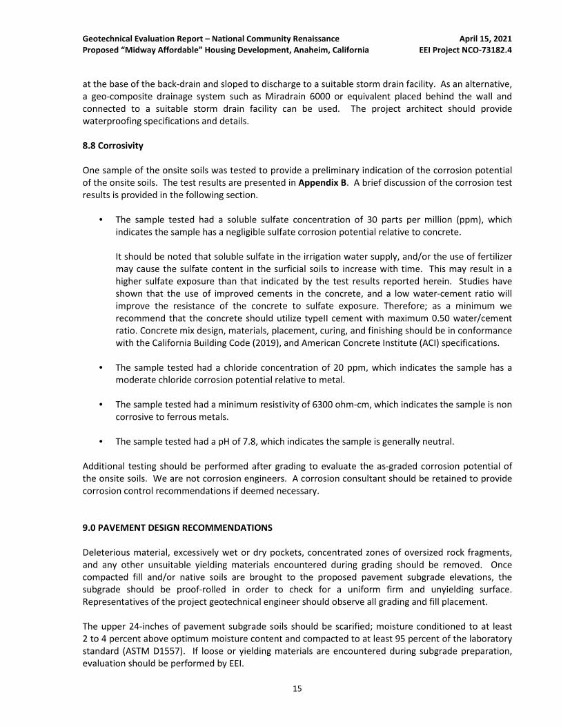
One sample of the onsite soils was tested to provide a preliminary indication of the corrosion potential
of the onsite soils. The test results are presented in Appendix B. A brief discussion of the corrosion test
results is provided in the following section.
• The sample tested had a soluble sulfate concentration of 30 parts per million (ppm), which
indicates the sample has a negligible sulfate corrosion potential relative to concrete.
It should be noted that soluble sulfate in the irrigation water supply, and/or the use of fertilizer
may cause the sulfate content in the surficial soils to increase with time. This may result in a
higher sulfate exposure than that indicated by the test results reported herein. Studies have
shown that the use of improved cements in the concrete, and a low water-cement ratio will
improve the resistance of the concrete to sulfate exposure. Therefore; as a minimum we
recommend that the concrete should utilize typeII cement with maximum 0.50 water/cement
ratio. Concrete mix design, materials, placement, curing, and finishing should be in conformance
with the California Building Code (2019), and American Concrete Institute (ACI) specifications.
• The sample tested had a chloride concentration of 20 ppm, which indicates the sample has a
moderate chloride corrosion potential relative to metal.
• The sample tested had a minimum resistivity of 6300 ohm-cm, which indicates the sample is non
corrosive to ferrous metals.
• The sample tested had a pH of 7.8, which indicates the sample is generally neutral.
Additional testing should be performed after grading to evaluate the as-graded corrosion potential of
the onsite soils. We are not corrosion engineers. A corrosion consultant should be retained to provide
corrosion control recommendations if deemed necessary.
9.0 PAVEMENT DESIGN RECOMMENDATIONS
Deleterious material, excessively wet or dry pockets, concentrated zones of oversized rock fragments,
and any other unsuitable yielding materials encountered during grading should be removed. Once
compacted fill and/or native soils are brought to the proposed pavement subgrade elevations, the
subgrade should be proof-rolled in order to check for a uniform firm and unyielding surface.
Representatives of the project geotechnical engineer should observe all grading and fill placement.
The upper 24-inches of pavement subgrade soils should be scarified; moisture conditioned to at least
2 to 4 percent above optimum moisture content and compacted to at least 95 percent of the laboratory
standard (ASTM D1557). If loose or yielding materials are encountered during subgrade preparation,
evaluation should be performed by EEI.

Geotechnical Evaluation Report – National Community Renaissance April 15, 2021
Proposed “Midway Affordable” Housing Development, Anaheim, California EEI Project NCO-73182.4
16
Aggregate base materials should be properly prepared (i.e., processed and moisture conditioned) and
compacted to at least 95 percent of the maximum dry density as determined by ASTM D1557. All
pavement section changes should be properly transitioned. Although not anticipated, if adverse
conditions are encountered during the preparation of subgrade materials, special construction methods
may need to be employed. A representative of the project geotechnical engineer should be present for
the preparation of subgrade and aggregate base. For preliminary design purposes, we have assumed an
R-Value of 15 for the materials likely to be exposed at subgrade. For design purposes we have assumed
a Traffic Index (TI) of 5.0 for the parking stalls and a Traffic Index (TI) of 6.0 for drive areas. This assumed
TI should be verified as necessary by the Civil Engineer or Traffic Engineer.
TABLE 3
Preliminary Pavement Design Recommendations
Traffic Index (TI) / Intended Use Pavement Surface Aggregate Base Material (1)
5 3.0-inches Asphalt Concrete 8.0-inches
6 3.0-inches Asphalt Concrete 11.0-inches
Concrete Pavement Section 6.0-inches Portland Cement Concrete 6.0-inches
(1) R-Value of 78 for Caltrans Class 2 aggregate base
The recommended pavement sections provided in Table 3 are intended as a minimum guideline. If
thinner or highly variable pavement sections are constructed, increased maintenance and repair could
be expected. If the actual traffic index (TI) increases beyond our assumed values, increased
maintenance and repair could be required for the pavement section. Final pavement design should be
verified by testing of soils exposed at subgrade after grading has been completed. Thicker pavement
sections could result if R-Value testing indicates lower values.
10.0 DEVELOPMENT RECOMMENDATIONS
10.1 Landscape Maintenance and Planting
Water is known to decrease the physical strength of earth materials, significantly reducing stability by
high moisture conditions. Surface drainage away from foundations and graded slopes should be
maintained. Only the volume and frequency of irrigation necessary to sustain plant life should be
applied.
Consideration should be given to selecting lightweight, deep rooted types of landscape vegetation which
require low irrigation that are capable of surviving the local climate. From a soils engineering viewpoint,
“leaching” of the onsite soils is not recommended for establishing landscaping. If landscape soils are
processed for the addition of amendments, the processed soils should be re-compacted to at least 90
percent relative compaction (based on ASTM D1557).

Geotechnical Evaluation Report – National Community Renaissance April 15, 2021
Proposed “Midway Affordable” Housing Development, Anaheim, California EEI Project NCO-73182.4
17
10.2 Site Drainage
Positive site drainage should be maintained at all times. Drainage should not flow uncontrolled over
slopes. Runoff should be channeled away from slopes and structures and not allowed to pond and/or
seep uncontrolled into the ground. Pad drainage should be directed toward an acceptable outlet.
Consideration should be given to eliminating open bottom planters directly adjacent to proposed
structures for a minimum distance of 10 feet. As an alternative, closed-bottom type planters could be
utilized, with a properly designed drain outlet placed in the bottom of the planter.
Final surface grades around structures should be designed to collect and direct surface water away from
structures and toward appropriate drainage facilities. The ground around the structure should be
graded so that surface water flows rapidly away from the structure without ponding. In general, we
recommend that the ground adjacent to the structure slope away at a gradient of at least 2 percent.
Densely vegetated areas where runoff can be impaired should have a minimum gradient of at least
5 percent within the first 5 feet from the structure. Roof gutters with downspouts that discharge
directly into a closed drainage system are recommended on structures. Drainage patterns established
at the time of fine grading should be maintained throughout the life of the proposed structures.
10.3 Site Runoff Considerations - Stormwater Disposal Systems
To comply with the Standard Urban Stormwater Mitigation Plan (SUSMP) requirements it is our
understanding that an onsite water retention system for the proposed development is contemplated.
For this reason we performed percolation testing at the site in order to provide a preliminary indication
of the infiltration characteristics of the onsite materials.
Percolation tests were performed in borings B-4/P-1 and B-5/P-2. The approximate locations of the
percolation wells are identified on Boring Location Map (Figure 3). Percolation test wells were
constructed by inserting 3-inch-diameter perforated PVC pipe in the borings and backfilling the annular
space with ⅜-inch gravel to prevent caving during the percolation test. Following construction of the
percolation test wells, they were filled with water and pre-saturated. Percolation testing was then
performed, and consisted of refilling the test wells with water to approximate referenced elevation and
taking a reading of drop in water level every ten minutes for a period of approximately one hour.
Table 4 presents the measured percolation and corresponding infiltration rates calculated for the test
holes.
TABLE 4
Summary of Percolation Testing
Location Depth (ft.) Pre-Adjusted Percolation Rate (in/hr.) Infiltration Rate (in/hr.)
B-4/P-1 11.3 480 90
B-5/P-2 19.15 122.4 7.95

Geotechnical Evaluation Report – National Community Renaissance April 15, 2021
Proposed “Midway Affordable” Housing Development, Anaheim, California EEI Project NCO-73182.4
18
The percolation test results are presented in Appendix C. It must be realized that the infiltration rates
presented above are as tested infiltration rates and do not include a factor of safety used for design
rates. The project civil engineer should determine the appropriate factor of safety for the proposed
disposal system. We note that only conceptual plans were available at the time of this evaluation, and
the design and location of a storm water dissipation/retention system has not yet been determined.
Therefore our percolation test was performed in soils that are generally representative of the overall
property.
10.4 Structure Setback from Retention Devices
We recommend that retention/disposal devices be situated at least three times their depth, or a
minimum of 15 feet (whichever is greater), from the outside bottom edge of structural foundations.
Structural foundations include (but are not limited to) buildings, loading docks, retaining walls, and
screen walls. All stormwater disposal systems should be checked and maintained on regular intervals.
Stormwater devices including bioswales that are located closer than 10 feet from any
foundations/footings should be lined with an impermeable membrane to reduce the potential for
saturation of foundation soils. Foundations may also need to be deepened.
10.5 Additional Site Improvements
Recommendations for additional grading can be provided upon request. If in the future, additional
property improvements are planned for the subject property, recommendations concerning the design
and construction of improvements would be provided upon request.
10.6 Utility Trench Backfill
Fill around the pipe should be placed in accordance with details shown on the drawings, and should be
placed in layers not to exceed 8-inches loose (unless otherwise approved by the geotechnical engineer)
and compacted to at least 90 percent of the maximum dry density as determined in accordance with
ASTM D1557 (Modified Proctor). The geotechnical engineer should approve all backfill material.
Select material should be used when called for on the drawings, or when recommended by the
geotechnical engineer. Care should be taken during backfill and compaction operations to maintain
alignment and prevent damage to the joints. The backfill should be kept free from oversized material,
chunks of highly plastic clay, or other unsuitable or deleterious material. Backfill soils should be non-
expansive, non-corrosive, and compatible with native earth materials. Backfill materials and testing
should be in accordance with the IBC (2012), and the requirements of the local governing jurisdiction.
Pipe backfill areas should be graded and maintained in such a condition that erosion or saturation will
not damage the pipe bedding or backfill. Flooding trench backfill is not recommended. Heavy
equipment should not be operated over any pipe until it has been properly backfilled with a minimum of
2 to 3 feet of cover. The utility trench should be systematically backfilled to allow maximum time for
natural settlement. Backfill should not occur over porous, wet, or spongy subgrade surfaces. Should
these conditions exist, the areas should be removed, replaced and recompacted.

Geotechnical Evaluation Report – National Community Renaissance April 15, 2021
Proposed “Midway Affordable” Housing Development, Anaheim, California EEI Project NCO-73182.4
19
11.0 PLAN REVIEW
Once detailed grading and foundation plans are available, they should be submitted to EEI for review
and comment, to reduce the potential for discrepancies between plans and recommendations
presented herein. If conditions are found to differ substantially from those stated, appropriate
recommendations will be provided. Additional field studies may be warranted.
12.0 LIMITATIONS
This Geotechnical Evaluation has been conducted in accordance with generally accepted geotechnical
engineering principles and practices. Findings provided herein have been derived in accordance with
current standards of practice, and no warranty is expressed or implied. Standards of practice are subject
to change with time. This report has been prepared for the sole use of National Community Renaissance
(Client), within a reasonable time from its authorization. Subject property conditions, land use (both
onsite and offsite), or other factors may change as a result of manmade influences, and additional work
may be required with the passage of time.
This Geotechnical Evaluation should not be relied upon by other parties without the express written
consent of EEI and the Client; therefore, any use or reliance upon this Geotechnical Evaluation by a party
other than the Client should be solely at the risk of such third party and without legal recourse against
EEI, its employees, officers, or directors, regardless of whether the action in which recovery of damages
is brought or based upon contract, tort, statue, or otherwise. The Client has the responsibility to see
that all parties to the project, including the designer, contractor, subcontractor, and building official, etc.
are aware of this report in its complete form. This report contains information that may be used in the
preparation of contract specifications; however, the report is not designed as a specification document,
and may not contain sufficient information for use without additional assessment. EEI assumes no
responsibility or liability for work or testing performed by others. In addition, this report may be subject
to review by the controlling authorities.

Geotechnical Evaluation Report – National Community Renaissance April 15, 2021
Proposed “Midway Affordable” Housing Development, Anaheim, California EEI Project NCO-73182.4
FIGURES

FIGURE 1
SITE VICINITY MAPNational Community Renaissance
Proposed “Midway Affordable” Housing Development
SWC W. Midway Dr and S. Anaheim Ave
Anaheim, Orange County, CA
EEI Project NCO-73182.4
Scale: 1" = 4,900 feet
Note: All Locations Are Approximate
4,900 ft
USGS US Topo 7.5-minute map for Anaheim, CA 2018
LEGEND
9,800 ft2,450 ft0
SITE VICINITY

FIGURE 2
AERIAL SITE MAPNational Community Renaissance
Proposed “Midway Affordable” Housing Development
SWC W. Midway Dr and S. Anaheim Ave
Anaheim, Orange County, CA
EEI Project NCO-73182.4
Source: Google Earth, 2021
Scale: 1" = 64'
Note: All Locations Are Approximate
64 ft 128 ft32 ft0
SUBJECT
PROPERTY
BOUNDARY

FIGURE 3
GEOTECHNICAL MAPNational Community Renaissance
Proposed “Midway Affordable” Housing Development
SWC W. Midway Dr and S. Anaheim Ave
Anaheim, Orange County, CA
EEI Project NCO-73182.4
Source: Google Earth, 2021
SUBJECT
PROPERTY
BOUNDARY
Approximate locations of exploratory boringsB-1
Approximate location of percolation tests B-4/P-1
B-1B-3
B-2
B-6
B-4/P-1
B-5/P-2
TP-6
TP-4
TP-1
TP-2
TP-3
TP-5
TP-4
Scale: 1" = 64'
Note: All Locations Are Approximate
64 ft 128 ft32 ft0
Scale: 1" = 64'
Note: All Locations Are Approximate
64 ft 128 ft32 ft0
Approximate location of test pits

Geotechnical Evaluation Report – National Community Renaissance April 15, 2021
Proposed “Midway Affordable” Housing Development, Anaheim, California EEI Project NCO-73182.4
APPENDIX A
SOIL CLASSIFICATION CHART AND BORING LOGS

Sou
th M
elr
ose
Driv
e
SYMBOLS
GRAPH LETTERTYPICAL DESCRIPTIONSMAJOR DIVISIONS
GW
GP
GM
GC
SW
SP
SM
SC
ML
CL
OL
MH
CH
OH
COARSEGRAINED
SOILS
GRAVEL
ANDGRAVELLY
SOILS
CLEANGRAVELS
(LITTLE OR NO FINES)
GRAVELS WITH
FINES
(APPRECIABLEAMOUNT OF FINES)
MORE THAN 50%
OF COARSEFRACTION
RETAINED ON NO.4 SEIVE
WELL-GRADED GRAVELS, GRAVEL- SAND
MIXTURES, LITTLE OR NO FINES
POORLY-GRADED GRAVELS, GRAVEL-SAND MIXTURES, LITTLE OR NO FINES
SILTY GRAVELS, GRAVEL-SAND-SILT MIXTURES
CLAYEY GRAVELS, GRAVEL-SAND- CLAY MIXTURES
WELL-GRADED SANDS,GRAVELLY SANDS,LITTLE OR NO FINESCLEAN SANDS
(LITTLE OR NO FINES)
(APPRECIABLEAMOUNT OF FINES)
SANDS WITH FINES
SAND
ANDSANDYSOILS
MORE THAN 50%OF COARSEFRACTION
REATINED ON NO.4 SEIVE
MORE THAN 50%OF MATERIAL ISLARGER THAN NO. 200 SIEVE
SIZE
POORLY-GRADED SANDS, GRAVELLY SAND, LITTLE OR NO FINES
SILTY-SANDS, SAND – SILT MIXTURES
CLAYEY SANDS, SAND – CLAY MIXTURES
FINEGRAINED
SOILS
SILTSAND
CLAYS
LIQUID LIMIT
LESS THAN 50
SILTSAND
CLAYS
LIQUID LIMITGREATER THAN 50
MORE THAN 50%OF MATERIAL IS
SMALLER THAN NO. 200 SIEVE
SIZE
INORGANIC SILTS AND VERY FINE SANDS, ROCK FLOUR, SILTY OR CLAYEY FINE SANDS OR CLAYEY SILTS WITH SLIGHT PLASTICITY
INORGANIC CLAYS OF LOW TO MEDIUM PLASTICITY, GRAVELLY CLAYS, SANDY CLAYS, SILTY CLAYS, LEAN CLAYS
ORGANIC SILTS AND ORGANIC SILTY CLAYS OF LOW PLASTICITY
INORGANIC SILTS, MICACEOUS ORDIATOMACEOUS FINE SAND OR SILTY SOILS
INORGANIC CLAYS OF HIGH PLASTICITY
ORGANIC CLAYS OF MEDIUM TO HIGH PLASTICITY, ORGANIC SILTS
SAMPLER TYPES
SPT
Modified California (2.5" I.D.)
Bulk
Shelby Tube
Rock Core
OTHER TESTS
COR – Corrosivity)
CD – Consolidated Drained Triaxial
CON – Consolidation
DS – Direct Shear
RV – R-Value
SA – Sieve Analysis
ATT – Atterberg Limit (Plasticity Index)
TV – Torvane Shear
UU – Unconsolidated Undrained
Triaxial
PLASTICITY CHART
Pla
sticity I
nd
ex (
%)
0
0Liquid Limit (%)
10
20
30
40
50
60
70
80
10 20 30 40 50 60 70 80 90 100 110 120
CL-ML
CL
“A” L
INE
CH
OH & MH
Water Level
PENETRATION RESISTANCE(Recorded As Blows/Foot)
SAND & GRAVEL SILT & CLAY
Relative Density
Very Loose
Loose
Medium Dense
Dense
Very Dense
Blows/Foot* N
0-4
4-10
10-30
30-50
Over 50
Consistency
Very Soft
Soft
Medium Stiff
Stiff
Very Stiff
Blows/Foot* N
0 - 2
2 - 4
4 - 8
Over 30
8 - 15
Hard
15 - 30
Strength**(KSF)0 – 0.5
0.5 – 1.0
1.0 – 2.0
Over 8.0
2.0 – 4.0
4.0 – 8.0
* Number of blows of 140LB hammer falling 30 inches to drive a 2 inch O.D. (1-3/8 inch I.D.) split barrel sampler the last 12 inches of an 18-inch drive (ASTM-1586 Standard Penetration Test)
60 60
** Undrained shear strength in kips/sq. ft. As determined by
laboratory testing or approximated by the standard penetration test, pocket penetrometer, torvane, or visual observation
UNIFIED SOIL CLASSIFICATION (ASTM D-2487-98)
Geotechnical & Environmental Solutions
LEGEND TO SOIL
DESCRIPTIONSAPPENDIX A
EI – Expansion Index
MAX – Maximum Density
-#200 - Percent Passing #200 Sieve

Artificial Fill (Af)Silty SAND (SM) dark brown, slighly moist to moist, medium dense, fine to coarsegrained with gravel and fragments of asphalt.
Quaternary Alluvium (Qal)Silty SAND (SP-SM) tan to light gray, slightly moist to moist, medium dense, fine tovery coarse grained.
Silty SAND (SP-SM) tan to light gray, moist, dense, fine to coarse grained.
Silty SAND (SM) brown, moist, medium dense, very fine to medium grained, lowtomoderate plasticity.
16
1
1
2
4
6
15
SM
SP-SM
SP-SM
SM
96
141614
1089
71014
91218
111726
91317
81619
MC
MC
SPT
MC
MC
MC
MC
MC
116
90
113
89
101
103
114
B-1
3/23/20213/23/2021
1 of 2
8"Ingersoll-Rand A300 / 8" Hollow Stem Auger 140 lbs Manual Hammer
Bulk
BS
National Community Renaissance
Project No.:
NCO-73182.4
Proposed "Midway Affordable" Housing Development
Geologic Description
SAMPLE LOG
Moisture(%)
GraphicLog
BOREHOLE LOG
Borehole Diameter:Drill Rig/Sampling Method
BOREHOLE LOG
USCSSymbol (SoilType, Color, Grain, Minor Soil Component, Moisture, Density, Odor, Etc.)
EEI Rep:
Client:
Location:
Date Started:SWC W. Midway Dr and S. Anaheim Ave
Date Finished:
Number:
Sheet:
BlowsPer 6"
DepthIn
Feet
1
2
3
4
5
6
7
8
9
10
11
12
13
14
15
16
17
18
19
20
21
22
23
24
25
26
27
28
29
30
31
32
33
34
SampleType
Dry UnitWt. (pcf)
BO
RE
HO
LE L
OG
NC
O-7
3182
.4.G
PJ
EEI
.GD
T 4
/10/
21

Silty SAND (SP-SM) tan to light gray, moist, dense, fine to coarse grained.
Sandy SILT (ML) yellowish brown to greenish brown, moist, medium dense, fine tocoarse grained.
Silty SAND (SP-SM) tan to light gray, moist, dense, fine to coarse grained.
Total Depth: 51.5' bgsNo groundwater encounteredBackfilled with native soil
9
24
4
2
SP-SM
ML
SP-SM
172843
71020
3550-5"
2346
50-5"
MC
MC
MC
MC
106
100
109
106
B-1
3/23/20213/23/2021
2 of 2
8"Ingersoll-Rand A300 / 8" Hollow Stem Auger 140 lbs Manual Hammer
Bulk
BS
National Community Renaissance
Project No.:
NCO-73182.4
Proposed "Midway Affordable" Housing Development
Geologic Description
SAMPLE LOG
Moisture(%)
GraphicLog
BOREHOLE LOG
Borehole Diameter:Drill Rig/Sampling Method
BOREHOLE LOG
USCSSymbol (SoilType, Color, Grain, Minor Soil Component, Moisture, Density, Odor, Etc.)
EEI Rep:
Client:
Location:
Date Started:SWC W. Midway Dr and S. Anaheim Ave
Date Finished:
Number:
Sheet:
BlowsPer 6"
DepthIn
Feet
36
37
38
39
40
41
42
43
44
45
46
47
48
49
50
51
52
53
54
55
56
57
58
59
60
61
62
63
64
65
66
67
68
69
SampleType
Dry UnitWt. (pcf)
BO
RE
HO
LE L
OG
NC
O-7
3182
.4.G
PJ
EEI
.GD
T 4
/10/
21

Artificial Fill (Af)Silty SAND (SM) brown to greenish brown, slighly moist, medium dense, fine tocoarse grained with gravel.
Quaternary Alluvium (Qal)Silty SAND (SM) tan to light gray, moist, medium dense, fine to coarse grained.
Silty SAND (SM) tan to light gray, moist, medium dense, fine to very coarse.
Silty SAND (SM) brown to greenish brown, moist, medium dense, very fine tomedium grained, low to moderate plasticity.
Total Depth: 26.5' bgsNo groundwater encounteredBackfilled with native soils
5
12
SM
SM
SM
SM
121316
333
565
675
888
5811
71114
MC
SPT
SPT
SPT
SPT
SPT
MC
107
117
B-2
3/23/20213/23/2021
1 of 1
8"Ingersoll-Rand A300 / 8" Hollow Stem Auger 140 lbs Manual Hammer
Bulk
BS
National Community Renaissance
Project No.:
NCO-73182.4
Proposed "Midway Affordable" Housing Development
Geologic Description
SAMPLE LOG
Moisture(%)
GraphicLog
BOREHOLE LOG
Borehole Diameter:Drill Rig/Sampling Method
BOREHOLE LOG
USCSSymbol (SoilType, Color, Grain, Minor Soil Component, Moisture, Density, Odor, Etc.)
EEI Rep:
Client:
Location:
Date Started:SWC W. Midway Dr and S. Anaheim Ave
Date Finished:
Number:
Sheet:
BlowsPer 6"
DepthIn
Feet
1
2
3
4
5
6
7
8
9
10
11
12
13
14
15
16
17
18
19
20
21
22
23
24
25
26
27
28
29
30
31
32
33
34
SampleType
Dry UnitWt. (pcf)
BO
RE
HO
LE L
OG
NC
O-7
3182
.4.G
PJ
EEI
.GD
T 4
/10/
21

Artificial Fill (Af)Silty SAND (SP-SM) dark brown, moist, medium dense, fine to coarse grained withgravel.
Quaternary Alluvium (Qal)SAND (SP) tan to dark gray, moist, medium dense, fine to coarse grained.
SAND (SP) tan to dark gray, moist, medium dense, fine to coarse grained.
Silty SAND (SM) tan to light gray, moist, medium dense, fine to very coarse grained.
Sandy SILT (ML) brown, moist, medium dense, very fine to medium grained, low tomoderate plasticity.
Total Depth: 26.5' bgsNo groundwater encounteredBackfilled with native soils
5
2
2
3
19
SP-SM
SP
SP
SM
ML
3711
856
91114
101216
91011
91112
7912
MC
MC
MC
MC
SPT
SPT
MC
113
104
101
101
109
B-3
3/23/20213/23/2021
1 of 1
8"Ingersoll-Rand A300 / 8" Hollow Stem Auger 140 lbs Manual Hammer
Bulk
BS
National Community Renaissance
Project No.:
NCO-73182.4
Proposed "Midway Affordable" Housing Development
Geologic Description
SAMPLE LOG
Moisture(%)
GraphicLog
BOREHOLE LOG
Borehole Diameter:Drill Rig/Sampling Method
BOREHOLE LOG
USCSSymbol (SoilType, Color, Grain, Minor Soil Component, Moisture, Density, Odor, Etc.)
EEI Rep:
Client:
Location:
Date Started:SWC W. Midway Dr and S. Anaheim Ave
Date Finished:
Number:
Sheet:
BlowsPer 6"
DepthIn
Feet
1
2
3
4
5
6
7
8
9
10
11
12
13
14
15
16
17
18
19
20
21
22
23
24
25
26
27
28
29
30
31
32
33
34
SampleType
Dry UnitWt. (pcf)
BO
RE
HO
LE L
OG
NC
O-7
3182
.4.G
PJ
EEI
.GD
T 4
/10/
21

Artificial Fill (Af)Silty SAND (SM) light gray, slighly moist, medium dense, very fine to very coarsegrained with gravel.
Quaternary Alluvium (Qal)Silty SAND (SM) greenish yellow to tan, slightly moist, medium dense, fine to verycoarse grained.
Silty SAND (SM) yellowish brown to light gray, moist, loose, fine to coarse grained.
Silty SAND (SM) yellowish brown to light gray, moist, medium dense, fine to verycoarse grained.
Total Depth: 11.5' bgsNo groundwater encounteredPercolation test performedBackfilled with native soils
6
SM
SM
SM
SM
81010
544
766
788
MC
SPT
SPT
SPT
102
B-4/P-1
3/23/20213/23/2021
1 of 1
8"Ingersoll-Rand A300 / 8" Hollow Stem Auger 140 lbs Manual Hammer
Bulk
BS
National Community Renaissance
Project No.:
NCO-73182.4
Proposed "Midway Affordable" Housing Development
Geologic Description
SAMPLE LOG
Moisture(%)
GraphicLog
BOREHOLE LOG
Borehole Diameter:Drill Rig/Sampling Method
BOREHOLE LOG
USCSSymbol (SoilType, Color, Grain, Minor Soil Component, Moisture, Density, Odor, Etc.)
EEI Rep:
Client:
Location:
Date Started:SWC W. Midway Dr and S. Anaheim Ave
Date Finished:
Number:
Sheet:
BlowsPer 6"
DepthIn
Feet
1
2
3
4
5
6
7
8
9
10
11
12
13
14
15
16
17
18
19
20
21
22
23
24
25
26
27
28
29
30
31
32
33
34
SampleType
Dry UnitWt. (pcf)
BO
RE
HO
LE L
OG
NC
O-7
3182
.4.G
PJ
EEI
.GD
T 4
/10/
21

Artificial Fill (Af)Silty SAND (SM) dark brown, slighly moist to moist, medium dense, fine to coarsegrained with gravel.
Quaternary Alluvium (Qal)Silty SAND (SM) brown to tan, moist, medium dense, fine to coarse grained.
Silty SAND (SM) tan to light gray, moist, medium dense, fine to very coarse grained.
Total Depth: 21.5' bgsNo groundwater encounteredPercolation test performedBackfilled with native soils
3
SM
SM
SM
7912
549
567
666
778
91314
MC
SPT
SPT
SPT
SPT
SPT
133
B-5/P-2
3/23/20213/23/2021
1 of 1
8"Ingersoll-Rand A300 / 8" Hollow Stem Auger 140 lbs Manual Hammer
Bulk
BS
National Community Renaissance
Project No.:
NCO-73182.4
Proposed "Midway Affordable" Housing Development
Geologic Description
SAMPLE LOG
Moisture(%)
GraphicLog
BOREHOLE LOG
Borehole Diameter:Drill Rig/Sampling Method
BOREHOLE LOG
USCSSymbol (SoilType, Color, Grain, Minor Soil Component, Moisture, Density, Odor, Etc.)
EEI Rep:
Client:
Location:
Date Started:SWC W. Midway Dr and S. Anaheim Ave
Date Finished:
Number:
Sheet:
BlowsPer 6"
DepthIn
Feet
1
2
3
4
5
6
7
8
9
10
11
12
13
14
15
16
17
18
19
20
21
22
23
24
25
26
27
28
29
30
31
32
33
34
SampleType
Dry UnitWt. (pcf)
BO
RE
HO
LE L
OG
NC
O-7
3182
.4.G
PJ
EEI
.GD
T 4
/10/
21

Artificial Fill (Af)Silty SAND (SM) brown to greenish brown, moist, medium dense,very fine to coarsegrained with gravel.
Quaternary Alluvium (Qal)Silty SAND (SM) brown to greenish brown, moist, medium dense, very fine to coarsegrained.
Silty SAND (SM) tan to light gray, moist, medium dense, fine to very coarsegrained.
Sandy SILT (ML) greenish brown to dark brown, moist, medium dense, very fine tomedium grained, low to moderate plasticity.
Total Depth: 26.5' bgsNo groundwater encounteredBackfilled with native soils
8
21
SP-SM
SM
SM
ML
477
555
345
444
787
6711
5711
MC
SPT
SPT
SPT
SPT
SPT
MC
108
104
B-6
3/23/20213/23/2021
1 of 1
8"Ingersoll-Rand A300 / 8" Hollow Stem Auger 140 lbs Manual Hammer
Bulk
BS
National Community Renaissance
Project No.:
NCO-73182.4
Proposed "Midway Affordable" Housing Development
Geologic Description
SAMPLE LOG
Moisture(%)
GraphicLog
BOREHOLE LOG
Borehole Diameter:Drill Rig/Sampling Method
BOREHOLE LOG
USCSSymbol (SoilType, Color, Grain, Minor Soil Component, Moisture, Density, Odor, Etc.)
EEI Rep:
Client:
Location:
Date Started:SWC W. Midway Dr and S. Anaheim Ave
Date Finished:
Number:
Sheet:
BlowsPer 6"
DepthIn
Feet
1
2
3
4
5
6
7
8
9
10
11
12
13
14
15
16
17
18
19
20
21
22
23
24
25
26
27
28
29
30
31
32
33
34
SampleType
Dry UnitWt. (pcf)
BO
RE
HO
LE L
OG
NC
O-7
3182
.4.G
PJ
EEI
.GD
T 4
/10/
21

Geotechnical Evaluation Report – National Community Renaissance April 15, 2021
Proposed “Midway Affordable” Housing Development, Anaheim, California EEI Project NCO-73182.4
APPENDIX B
LABORATORY TEST DATA
Laboratory tests were performed to provide geotechnical parameters for engineering analyses. The
following tests were performed:
• CLASSIFICATION: Field classifications were verified in the laboratory by visual examination. The
final soil classifications are in accordance with the Unified Soil Classification System.
• MOISTURE CONTENT and DRY DENSITY: The in-situ moisture content and dry density of soils
was determined for soil samples obtained from the exploratory borings and were determined in
general accordance with ASTM D2216 and ASTM 2937, respectively.
• EXPANSION INDEX: The expansion index was determined on a select near-surface sample in
accordance with ASTM D4829.
• DIRECT SHEAR: Direct shear testing was performed in general accordance with ASTM D3080 on
a single sample with normal load increments of approximately 1,000, 1,700 and 2,500 psf.
• CORROSIVITY: Corrosion testing of representative soil samples included sulfate potential by
California Test 417, chloride potential by California Test 422, and soil minimum resistivity and pH
by California Test 643. The sample was tested at Clarkson Laboratory and Supply, Inc. located in
Chula Vista, California.

Moisture-Density Determination
Client: Samp Received.:
W.O.: Test By:
Date: Samples By:
Classification
Description
Color
Moisture Moist Dry Dry Dry Dry Moist Moist Moist
Consistancy
Misc.
WET DENSITY
Boring/Pit No. B-1
Depth (ft) Elev (ft) 2.5 5.0 10.0 15.0 20.0 25.0 30.0 35.0
Length of Sample (L) 6 5 5 6 6 5 6 6
Total Wet Weight (T) 1210.3 860.3 888.4 900.1 997.5 964.1 1189.7 1072.5
Total Ring Wt. (R) 252 330 210 252 252 330 252 252
Total Soil (S) [T-R] 958.3 530.3 678.4 648.1 745.5 634.1 937.7 820.5
Average Wt. (A) [S/L] 159.71667 106.06 135.68 108.01667 124.25 126.82 156.28333 136.75
GMS to LBS [A/453.6] 0.3521091 0.2338183 0.2991182 0.238132 0.2739198 0.2795855 0.34454 0.3014771
LBS to CF3 (.00256 cf) 134.39277 91.33529 114.16724 90.890069 104.54952 109.2131 131.50381 115.06758
Wet Density (pcf) 134.4 91.3 114.2 90.9 104.5 109.2 131.5 115.1
MOISTURE CONTENT
Tare No.
Wet Weight (g) 144.3 148.3 157.2 128.3 123.6 132.8 148.1 145.2
Dry Weight (g) 124.5 146.7 155.7 126 119.3 125 128.7 133.3
Tare (g)
Water 19.8 1.6 1.5 2.3 4.3 7.8 19.4 11.9
Percent Moisture 15.9% 1.1% 1.0% 1.8% 3.6% 6.2% 15% 9%
DRY DENSITY
Dry Density 116.0 90.3 113.1 89.3 100.9 102.8 114.3 105.6
Maximum Density
Percent Compaction
Percent Saturation** 98.9% 3.5% 5.5% 5.7% 15.0% 27.2% 89.4% 41.8%
*Av. Ring Weight (gms) 42 **Specific Gravity 2.65 Rev 8/1/2014
66
EEI
5932-E-SC
4/5/2021
3/26/2021
TR
Client
SM SP-SM SP SP-SM SP-SM SM SM SP-SM
Dark Olive
Brown Gray Gray Gray Gray
Olive
Brown
Olive
Brown
Olive
Brown
Dense
Medium
DenseDense
Medium
Dense Dense
Medium
Dense
Medium
Dense
Medium
Dense
Geosoils, Inc. 5741 Palmer Way Carlsbad CA 92010 (760) 438-3155
PageX:\clint\EXTERNAL R-VALUE FOLDER\5932 EEI\2021\04 April\5932_NCO-73182.4_M&DMoist.-Dens. (2)

Moisture-Density Determination
Client: Samp Received.:
W.O.: Test By:
Date: Samples By:
Classification
Description
Color
Moisture Moist Moist Moist Moist Moist Moist Moist Moist
Consistancy
Misc.
WET DENSITY
Boring/Pit No. B-1 B-2 B-3
Depth (ft) Elev (ft) 40.0 45.0 50.0 2.5 25.0 2.5 5.0 7.5
Length of Sample (L) 6 6 6 6 6 6 6 6
Total Wet Weight (T) 1137.7 1057.4 1021.7 1048.4 1188.2 1098.1 1003.8 987.6
Total Ring Wt. (R) 252 252 252 252 252 252 252 252
Total Soil (S) [T-R] 885.7 805.4 769.7 796.4 936.2 846.1 751.8 735.6
Average Wt. (A) [S/L] 147.61667 134.23333 128.28333 132.73333 156.03333 141.01667 125.3 122.6
GMS to LBS [A/453.6] 0.3254336 0.2959289 0.2828116 0.292622 0.3439888 0.3108833 0.2762346 0.2702822
LBS to CF3 (.00256 cf) 124.21129 112.94995 107.94335 111.68778 131.29345 118.65775 105.43304 103.16114
Wet Density (pcf) 124.2 112.9 107.9 111.7 131.3 118.7 105.4 103.2
MOISTURE CONTENT
Tare No.
Wet Weight (g) 149.2 120.6 142.4 118.6 146.5 119.2 135.5 125
Dry Weight (g) 120 116.5 139.8 113.4 130.4 113.5 133.3 122.7
Tare (g)
Water 29.2 4.1 2.6 5.2 16.1 5.7 2.2 2.3
Percent Moisture 24.3% 3.5% 1.9% 4.6% 12.3% 5.0% 2% 2%
DRY DENSITY
Dry Density 99.9 109.1 106.0 106.8 116.9 113.0 103.7 101.3
Maximum Density
Percent Compaction
Percent Saturation** 98.4% 18.1% 8.8% 22.2% 78.8% 28.7% 7.4% 7.8%
*Av. Ring Weight (gms) 42 **Specific Gravity 2.65 Rev 8/1/2014
EEI 3/26/2021
5932-E-SC TR
4/5/2021 Client
ML SP-SM SP SM SM SP-SM SP SP
Olive
Brown Gray Gray
Olive
Brown
Olive
Brown Gray Gray Gray
Dense
Medium
Dense
Medium
Dense Dense Dense Dense Dense Dense
Geosoils, Inc. 5741 Palmer Way Carlsbad CA 92010 (760) 438-3155
PageX:\clint\EXTERNAL R-VALUE FOLDER\5932 EEI\2021\04 April\5932_NCO-73182.4_M&DMoist.-Dens. (3)

Moisture-Density Determination
Client: Samp Received.:
W.O.: Test By:
Date: Samples By:
Classification
Description
Color
Moisture Moist Moist Moist Moist Moist Moist
Consistancy
Misc.
WET DENSITY
Boring/Pit No. B-3 B-4 B-5 B-6
Depth (ft) Elev (ft) 10.0 25.0 2.5 2.5 2.5 25.0
Length of Sample (L) 6 6 6 6 6 6
Total Wet Weight (T) 991.7 1176.1 1024.2 1231.3 1085.3 1152.9
Total Ring Wt. (R) 252 252 252 252 252 252
Total Soil (S) [T-R] 739.7 924.1 772.2 979.3 833.3 900.9
Average Wt. (A) [S/L] 123.28333 154.01667 128.7 163.21667 138.88333 150.15
GMS to LBS [A/453.6] 0.2717887 0.3395429 0.2837302 0.3598251 0.3061802 0.3310185
LBS to CF3 (.00256 cf) 103.73613 129.59653 108.29395 137.33783 116.86267 126.34295
Wet Density (pcf) 103.7 129.6 108.3 137.3 116.9 126.3
MOISTURE CONTENT
Tare No.
Wet Weight (g) 126.5 157.9 135.8 123.1 120.7 151.2
Dry Weight (g) 123.2 132.8 128.4 119.3 111.6 124.5
Tare (g)
Water 3.3 25.1 7.4 3.8 9.1 26.7
Percent Moisture 2.7% 18.9% 5.8% 3.2% 8.2% 21.4%
DRY DENSITY
Dry Density 101.0 109.0 102.4 133.1 108.1 104.0
Maximum Density
Percent Compaction
Percent Saturation** 11.1% 96.9% 24.8% 34.8% 40.7% 96.4%
*Av. Ring Weight (gms) 42 **Specific Gravity 2.65 Rev 8/1/2014
EEI 3/26/2021
5932-E-SC TR
4/5/2021 Client
SP ML SM SM SP-SM ML
Gray
Olive
Brown Gray Gray Gray
Olive
Brown
Medium
Dense Dense
Medium
Dense Dense Dense Dense
Geosoils, Inc. 5741 Palmer Way Carlsbad CA 92010 (760) 438-3155
PageX:\clint\EXTERNAL R-VALUE FOLDER\5932 EEI\2021\04 April\5932_NCO-73182.4_M&DMoist.-Dens. (4)
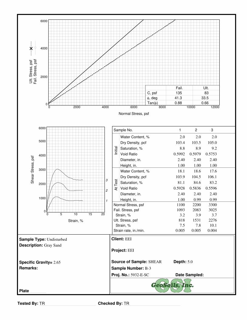
Tested By: TR Checked By: TR
Client: EEI
Project: EEI
Source of Sample: SHEAR Depth: 5.0
Sample Number: B-3
Proj. No.: 5932-E-SC Date Sampled:
Sample Type: Undisturbed
Description: Gray Sand
Specific Gravity= 2.65
Remarks:
Plate
Sample No.
Water Content, %
Dry Density, pcf
Saturation, %
Void Ratio
Diameter, in.
Height, in.
Water Content, %
Dry Density, pcf
Saturation, %
Void Ratio
Diameter, in.
Height, in.
Normal Stress, psf
Fail. Stress, psf
Strain, %
Ult. Stress, psf
Strain, %
Strain rate, in./min.
Initia
lA
t T
est
Sh
ea
r S
tre
ss, p
sf
0
1000
2000
3000
4000
5000
6000
Strain, %
0 5 10 15 20
1
2
3
Ult. S
tre
ss, p
sf
Fa
il. S
tre
ss, p
sf
0
2000
4000
6000
Normal Stress, psf
0 2000 4000 6000 8000 10000 12000
C, psf
φ, deg
Tan(φ)
Fail. Ult.
135
41.3
0.88
83
33.5
0.66
1
2.0
103.4
8.8
0.5992
2.40
1.00
18.1
103.9
81.1
0.5928
2.40
1.00
1100
1093
3.2
818
7.5
0.005
2
2.0
103.5
8.9
0.5979
2.40
1.00
18.6
104.5
84.6
0.5836
2.40
0.99
2200
2083
3.9
1531
7.8
0.005
3
2.0
105.0
9.2
0.5753
2.40
1.00
17.6
106.1
83.2
0.5596
2.40
0.99
3300
3025
3.7
2276
10.1
0.004

Tested By: TR Checked By: TR
4-5-21
(no specification provided)
PL= LL= PI=
D90= D85= D60=D50= D30= D15=D10= Cu= Cc=
USCS= AASHTO=
*
Gray Sand
.375#4#10#20#40#60
#100#200
100.098.894.773.741.315.2
4.92.0
1.5002 1.2115 0.61530.5016 0.3450 0.24890.2096 2.94 0.92
SP
NCO-73182.4
EEI
EEI
5932-E-SC
Soil Description
Atterberg Limits
Coefficients
Classification
Remarks
Source of Sample: Sieve Depth: 10.0Sample Number: B-1 Date:
Client:
Project:
Project No: Plate
SIEVE PERCENT SPEC.* PASS?
SIZE FINER PERCENT (X=NO)
PE
RC
EN
T F
INE
R
0
10
20
30
40
50
60
70
80
90
100
GRAIN SIZE - mm.
0.0010.010.1110100
% +3"Coarse
% Gravel
Fine Coarse Medium
% Sand
Fine Silt
% Fines
Clay
0.0 0.0 1.2 4.1 53.4 39.3 2.0
6 in.
3 in.
2 in.
1½
in.
1 in.
¾ in.
½ in.
3/8
in.
#4
#10
#20
#30
#40
#60
#100
#140
#200
Particle Size Distribution Report
Tested By: TR Checked By: TR
4-5-21
(no specification provided)
PL= LL= PI=
D90= D85= D60=D50= D30= D15=D10= Cu= Cc=
USCS= AASHTO=
*
Gray Sand w/Silt
.375#4#10#20#40#60
#100#200
100.099.899.193.074.949.124.913.4
0.7136 0.5764 0.30770.2541 0.1709 0.0908
SP-SM
NCO-73182.4
EEI
EEI
5932-E-SC
Soil Description
Atterberg Limits
Coefficients
Classification
Remarks
Source of Sample: Sieve Depth: 45.0Sample Number: B-1 Date:
Client:
Project:
Project No: Plate
SIEVE PERCENT SPEC.* PASS?
SIZE FINER PERCENT (X=NO)
PE
RC
EN
T F
INE
R
0
10
20
30
40
50
60
70
80
90
100
GRAIN SIZE - mm.
0.0010.010.1110100
% +3"Coarse
% Gravel
Fine Coarse Medium
% Sand
Fine Silt
% Fines
Clay
0.0 0.0 0.2 0.7 24.2 61.5 13.4
6 in.
3 in.
2 in.
1½
in.
1 in.
¾ in.
½ in.
3/8
in.
#4
#10
#20
#30
#40
#60
#100
#140
#200
Particle Size Distribution Report

Tested By: TR Checked By: TR
4-5-21
(no specification provided)
PL= LL= PI=
D90= D85= D60=D50= D30= D15=D10= Cu= Cc=
USCS= AASHTO=
*
Olive Brown Silty Sand
#10#20#40#60
#100#200
100.099.795.680.962.741.3
0.3330 0.2824 0.13830.1006
SM
NCO-73182.4
EEI
EEI
5932-E-SC
Soil Description
Atterberg Limits
Coefficients
Classification
Remarks
Source of Sample: Sieve Depth: 25.0Sample Number: B-2 Date:
Client:
Project:
Project No: Plate
SIEVE PERCENT SPEC.* PASS?
SIZE FINER PERCENT (X=NO)
PE
RC
EN
T F
INE
R
0
10
20
30
40
50
60
70
80
90
100
GRAIN SIZE - mm.
0.0010.010.1110100
% +3"Coarse
% Gravel
Fine Coarse Medium
% Sand
Fine Silt
% Fines
Clay
0.0 0.0 0.0 0.0 4.4 54.3 41.3
6 in.
3 in.
2 in.
1½
in.
1 in.
¾ in.
½ in.
3/8
in.
#4
#10
#20
#30
#40
#60
#100
#140
#200
Particle Size Distribution Report


Geotechnical Evaluation Report – National Community Renaissance April 15, 2021
Proposed “Midway Affordable” Housing Development, Anaheim, California EEI Project NCO-73182.4
APPENDIX C
FIELD PERCOLATION DATA

Well Installed? No
Start Finish
ft. ft. min. in. in./hr.
1 9:52 9:53 10.80 11.30 1 6.00 360.00
2 9:53 9:54 10.50 11.30 1 9.60 576.00
3 9:54 9:56 10.40 11.30 1.5 10.80 432.00
4 9:56 9:58 10.30 11.30 1.5 12.00 480.00
5 9:58 10:00 10.30 11.30 1.5 12.00 480.00
6 10:00 10:02 10.30 11.30 1.5 12.00 480.00
7
8
9
10
11
12
13
Project "Midway Affordable" By BS
Client National Community Renaissance Date 3/25/2021
Proj. No. NCO-73182.4 Page 1 of 2
PERCOLATION TEST
Borehole ID B-4/P-1Contractor EEI
Equipment/Rig (HSA)/Truck-Mounted A300
Presoak Start 3/25/2021 Boring Diameter 8-inches
Testing Start 3/25/2021 Boring Depth 11.3
in/hr
Time Depth to Water Elapsed
Time
Testing Completion 3/25/2021 Yes
NotesAfter pouring over 20 gallons into the boring hole the water was unable to hold a
stable head of water. A presoak was not needed.
ReadingStart Finish
Water
Drop
Perc.
Rate
Stabilized Percolation Rate = 480.00

Well Installed? No
Start Finish
ft. ft. min. in. in./hr.
1 10:37 10:47 15.35 17.85 10 30.00 180.00
2 10:47 10:57 16.05 17.90 10 22.20 133.20
3 10:57 11:07 15.65 17.80 10 25.80 154.80
4 11:07 11:17 15.85 17.75 10 22.80 136.80
5 11:17 11:27 15.95 17.65 10 20.40 122.40
6 11:27 11:37 15.90 17.60 10 20.40 122.40
7
8
9
10
11
12
13
Project "Midway Affordable" By BS
Client National Community Renaissance Date 3/25/2021
Proj. No. NCO-73182.4 Page 2 of 2
PERCOLATION TEST
Borehole ID B-5/P-2Contractor EEI
Equipment/Rig (HSA)/Truck-Mounted A300
Presoak Start 3/25/2021 Boring Diameter 8-inches
Testing Start 3/25/2021 Boring Depth 19.15
in/hr
Time Depth to Water Elapsed
Time
Testing Completion 3/25/2021 Yes
NotesAfter pouring over 35 gallons into the boring hole the water was unable to hold a
stable head of water. A presoak was not needed.
ReadingStart Finish
Water
Drop
Perc.
Rate
Stabilized Percolation Rate = 122.40

Geotechnical Evaluation Report – National Community Renaissance April 15, 2021
Proposed “Midway Affordable” Housing Development, Anaheim, California EEI Project NCO-73182.4
APPENDIX D
EARTHWORK and GRADING GUIDELINES
EARTHWORK AND GRADING GUIDELINES
GENERAL
These guidelines present general procedures and recommendations for earthwork and grading as
required on the approved grading plans, including preparation of areas to be filled, placement of
fill and installation of subdrains and excavations. The recommendations contained in the
geotechnical report are applicable to each specific project, are part of the earthwork and grading
guidelines and would supersede the provisions contained hereafter in the case of conflict.
Observations and/or testing performed by the consultant during the course of grading may
result in revised recommendations which could supersede these guidelines or the
recommendations contained in the geotechnical report. Figures A through O is provided at the
back of this appendix, exhibiting generalized cross sections relating to these guidelines.
The contractor is responsible for the satisfactory completion of all earthworks in accordance with
provisions of the project plans and specifications. The project soil engineer and engineering
geologist (geotechnical consultant) or their representatives should provide observation and
testing services, and geotechnical consultation throughout the duration of the project.
EARTHWORK OBSERVATIONS AND TESTING
Geotechnical Consultant
Prior to the commencement of grading, a qualified geotechnical consultant (a soil engineer and
engineering geologist) should be employed for the purpose of observing earthwork procedures
and testing the fills for conformance with the recommendations of the geotechnical report,
the approved grading plans, and applicable grading codes and ordinances.
The geotechnical consultant should provide testing and observation so that determination may
be made that the work is being completed as specified. It is the responsibility of the contractor
to assist the consultant and keep them aware of work schedules and predicted changes, so
that the consultant may schedule their personnel accordingly.
All removals, prepared ground to receive fill, key excavations, and subdrains should be
observed and documented by the project engineering geologist and/or soil engineer prior to
placing any fill. It is the contractor’s responsibility to notify the engineering geologist and soil
engineer when such areas are ready for observation.
Corporate Office: 2195 Faraday Ave., Suite K, Carlsbad, CA 92008-7207 Ph: 760-431-3747
www.eeitiger.com
Camarillo * Carlsbad * Pleasanton * Sacramento * Reno
Earthwork and Grading Guidelines
2
Laboratory and Field Tests
Maximum dry density tests to determine the degree of compaction should be performed in
accordance with American Standard Testing Materials test method ASTM designation
D-1557-78. Random field compaction tests should be performed in accordance with test
method ASTM designations D-1556-82, D-2937 or D-2922 & D-3017, at intervals of
approximately two feet of fill height per 10,000 sq. ft. or every one thousand cubic yards of fill
placed. These criteria would vary depending on the soil conditions and the size of the project.
The location and frequency of testing would be at the discretion of the geotechnical consultant
Contractor’s Responsibility
All clearing, site preparation, and earthwork performed on the project should be conducted by
the contractor, with observation by geotechnical consultants and staged approval by the
appropriate governing agencies. It is the contractor’s responsibility to prepare the ground
surface to receive the fill to the satisfaction of the soil engineer, and to place, spread, moisture
condition, mix and compact the fill in accordance with the recommendations of the soil
engineer. The contractor should also remove all major deleterious material considered
unsatisfactory by the soil engineer.
It is the sole responsibility of the contractor to provide adequate equipment and methods to
accomplish the earthwork in accordance with applicable grading guidelines, codes or agency
ordinances, and approved grading plans. Sufficient watering apparatus and compaction
equipment should be provided by the contractor with due consideration for the fill material, rate
of placement, and climatic conditions. If, in the opinion of the geotechnical consultant,
unsatisfactory conditions such as questionable weather, excessive oversized rock, deleterious
material or insufficient support equipment are resulting in a quality of work that is not
acceptable, the consultant will inform the contractor, and the contractor is expected to rectify
the conditions, and if necessary, stop work until conditions are satisfactory.
The contractor will properly grade all surfaces to maintain good drainage and prevent ponding
of water. The contractor will take action to control surface water and to prevent erosion
control measures that have been installed.
SITE PREPARATION
All vegetation including brush, trees, thick grasses, organic debris, and other deleterious
material should be removed and disposed of offsite, and must be concluded prior to placing fill.
Existing fill, soil, alluvium, colluvium, or rock materials determined by the soil engineer or
engineering geologist as unsuitable for structural in-place support should be removed prior to
fill placement. Depending upon the soil conditions, these materials may be reused as
compacted fills. Any materials incorporated as part of the compacted fills should be approved by
the soil engineer.
Any underground structures such as cesspools, cisterns, mining shafts, tunnels, septic
tanks, wells, pipelines, or other structures not located prior to grading are to be removed or
treated in a manner recommended by the soil engineer. Soft, dry, spongy, highly fractured,
or otherwise unsuitable ground extending to such a depth that surface processing cannot
adequately improve the condition should be over excavated down to firm ground and approved
by the soil engineer before compaction and filling operations continue. Over excavated and
processed soils which have been properly mixed and moisture-conditioned should be
recompacted to the minimum relative compaction as specified in these guidelines.

Earthwork and Grading Guidelines
3
Existing ground which is determined to be satisfactory for support of the fills should be scarified
to a minimum depth of 6 inches, or as directed by the soil engineer. After the scarified
ground is brought to optimum moisture (or greater) and mixed, the materials should be
compacted as specified herein. If the scarified zone is greater than 6 inches in depth, it may
be necessary to remove the excess and place the material in lifts restricted to 6 inches in
compacted thickness.
Existing grind which is not satisfactory to support compacted fill should be over excavated as
required in the geotechnical report or by the onsite soils engineer and/or engineering
geologists. Scarification, discing, or other acceptable form of mixing should continue until the
soils are broken down and free of large fragments or clods, until the working surface is
reasonably uniform and free from ruts, hollows, hummocks, or other uneven features which
would inhibit compaction as described above.
Where fills are to be placed on ground with slopes steeper than 5:1 (horizontal to vertical)
gradient, the ground should be benched. The lowest bench, which will act as a key, should be a
minimum of 12 feet wide and should be at least two feet deep into competent material,
approved by the soil engineer and/or engineering geologist. In fill over cut slope conditions, the
recommended minimum width of the lowest bench or key is at least 15 feet with the
key excavated on competent material, as designated by the Geotechnical Consultant. As a
general rule, unless superseded by the Soil Engineer, the minimum width of fill keys should be
approximately equal to one-half (½) the height of the slope.
Standard benching is typically four feet (minimum) vertically, exposing competent material.
Benching may be used to remove unsuitable materials, although it is understood that the
vertical height of the bench may exceed four feet. Pre stripping may be considered for removal
of unsuitable materials in excess of four feet in thickness.
All areas to receive fill, including processed areas, removal areas, and toe of fill benches should
be observed and approved by the soil engineer and/or engineering geologist prior to placement
of fill. Fills may then be properly placed and compacted until design grades are attained.
COMPACTED FILLS
Earth materials imported or excavated on the property may be utilized as fill provided that each
soil type has been accepted by the soil engineer. These materials should be free of roots,
tree branches, other organic matter or other deleterious materials. All unsuitable materials
should be removed from the fill as directed by the soil engineer. Soils of poor gradation,
undesirable expansion potential, or substandard strength characteristics may be designated
unsuitable by the consultant and may require mixing with other earth materials to serve as
a satisfactory fill material.
Fill materials generated from benching operations should be dispersed throughout the fill area.
Benching operations should not result in the benched material being placed only within a single
equipment width away from the fill/bedrock contact.

Earthwork and Grading Guidelines
4
Oversized materials, defined as rock or other irreducible materials with a maximum size
exceeding 12 inches in one dimension, should not be buried or placed in fills unless the location
of materials and disposal methods are specifically approved by the soil engineer. Oversized
material should be taken offsite or placed in accordance with recommendations of the soil
engineer in areas designated as suitable for rock disposal. Oversized material should not be
placed vertically within 10 feet of finish grade or horizontally within 20 feet of slope faces.
To facilitate trenching, rock should not be placed within the range of foundation excavations or
future utilities unless specifically approved by the soil engineer and/or the representative
developers.
If import fill material is required for grading, representative samples of the material should be
analyzed in the laboratory by the soil engineer to determine its physical properties. If any
material other than that previously analyzed is imported to the fill or encountered during
grading, analysis of this material should be conducted by the soil engineer as soon as practical.
Fill material should be placed in areas prepared to receive fill in near-horizontal layers that should
not exceed six inches compacted in thickness. The soil engineer may approve thicker lifts if
testing indicates the grading procedures are such that adequate compaction is being
achieved. Each layer should be spread evenly and mixed to attain uniformity of material and
moisture suitable for compaction.
Fill materials at moisture content less than optimum should be watered and mixed, and “wet”
fill materials should be aerated by scarification, or should be mixed with drier material.
Moisture conditioning and mixing of fill materials should continue until the fill materials have
uniform moisture content at or above optimum moisture.
After each layer has been evenly spread, moisture-conditioned and mixed, it should be uniformly
compacted to a minimum of 90 percent of maximum density as determined by ASTM test
designation, D 1557-78, or as otherwise recommended by the soil engineer. Compaction
equipment should be adequately sized and should be reliable to efficiently achieve the required
degree of compaction.
Where tests indicate that the density of any layer of fill, or portion thereof, is below the required
relative compaction or improper moisture content, the particular layer or portion will be
reworked until the required density and/or moisture content has been attained. No
additional fill will be placed in an area until the last placed lift of fill has been tested and found
to meet the density and moisture requirements, and is approved by the soil engineer.
Compaction of slopes should be accomplished by over-building the outside edge a minimum of
three feet horizontally, and subsequently trimming back to the finish design slope configuration.
Testing will be performed as the fill is horizontally placed to evaluate compaction as the fill core
is being developed. Special efforts may be necessary to attain the specified compaction in the
fill slope zone. Final slope shaping should be performed by trimming and removing loose
materials with appropriate equipment. A final determination of fill slope compaction should be
based on observation and/or testing of the finished slope face.

Earthwork and Grading Guidelines
5
If an alternative to over-building and cutting back the compacted fill slope is selected, then
additional efforts should be made to achieve the required compaction in the outer 10 feet of
each lift of fill by undertaking the following:
• Equipment consisting of a heavy short-shanked sheepsfoot should be used to roll
(horizontal) parallel to the slopes continuously as fill is placed. The sheepsfoot roller
should also be used to roll perpendicular to the slopes, and extend out over the slope
to provide adequate compaction to the face slope.
• Loose fill should not be spilled out over the face of the slope as each lift is compacted.
Any loose fill spilled over a previously completed slope face should be trimmed off or be
subject to re-rolling.
• Field compaction tests will be made in the outer two to five feet of the slope at two
to three foot vertical intervals, subsequent to compaction operations.
• After completion of the slope, the slope face should be shaped with a small dozer
and then re-rolled with a sheepsfoot to achieve compaction to near the slope face.
Subsequent to testing to verify compaction, the slopes should be grid-rolled to achieve
adequate compaction to the slope face. Final testing should be used to confirm
compaction after grid rolling.
• Where testing indicates less than adequate compaction, the contractor will be
responsible to process, moisture condition, mix and recompact the slope materials as
necessary to achieve compaction. Additional testing should be performed to verify
compaction.
• Erosion control and drainage devices should be designed by the project civil engineer in
compliance with the ordinances of the controlling governmental agencies, and/or in
accordance with the recommendations of the soil engineer or engineering geologist.
EXCAVATIONS
Excavations and cut slopes should be observed and mapped during grading by the engineering
geologist. If directed by the engineering geologist, further excavations or over-excavation and
refilling of cut areas should be performed. When fills over cut slopes are to be graded, the
cut portion of the slope should be observed by the engineering geologist prior to placement of
the overlying fill portion of the slope. The engineering geologist should observe all cut slopes
and should be notified by the contractor when cut slopes are started.
If, during the course of grading, unanticipated adverse or potentially adverse geologic conditions
are encountered, the engineering geologist and soil engineer should investigate, evaluate
and make recommendations to mitigate (or limit) these conditions. The need for cut slope
buttressing or stabilizing should be based on as-grading evaluations by the engineering
geologist, whether anticipated previously or not.
Unless otherwise specified in soil and geological reports, no cut slopes should be excavated
higher or steeper than that allowed by the ordinances of controlling governmental agencies.
Additionally, short-term stability of temporary cut slopes is the contractor’s responsibility.

Earthwork and Grading Guidelines
6
Erosion control and drainage devices should be designed by the project civil engineer and should
be constructed in compliance with the ordinances of the controlling governmental
agencies, and/or in accordance with the recommendations of the soil engineer or engineering
geologist.
SUBDRAIN INSTALLATION
Subdrains should be installed in accordance with the approved embedment material,
alignment and details indicated by the geotechnical consultant. Subdrain locations or
construction materials should not be changed or modified without approval of the
geotechnical consultant. The soil engineer and/or engineering geologist may recommend and
direct changes in subdrain line, grade and drain material in the field, pending exposed
conditions. The location of constructed subdrains should be recorded by the project civil
engineer.
COMPLETION
Consultation, observation and testing by the geotechnical consultant should be completed
during grading operations in order to state an opinion that all cut and filled areas are graded in
accordance with the approved project specifications.
After completion of grading and after the soil engineer and engineering geologist have finished
their observations, final reports should be submitted subject to review by the controlling
governmental agencies. No additional grading should be undertaken without prior notification
of the soil engineer and/or engineering geologist.
All finished cut and fill slopes should be protected from erosion, including but not limited to
planting in accordance with the plan design specifications and/or as recommended by a
landscape architect. Such protection and/or planning should be undertaken as soon as
possible after completion of grading.
ATTACHMENTS
Figure A – Transition Lot Detail Cut Lot
Figure B – Transition Lot Detail Cut - Fill
Figure C – Rock Disposal Pits
Figure D – Detail for Fill Slope Toeing out on a Flat Alluviated Canyon
Figure E – Removal Adjacent to Existing Fill
Figure F – Daylight Cut Lot Detail
Figure G – Skin Fill of Natural Ground
Figure H – Typical Stabilization Buttress Fill Design
Figure I – Stabilization Fill for Unstable Material Exposed in Portion of Cut Slope
Figure J – Fill Over Cut Detail
Figure K – Fill Over Natural Detail
Figure L – Oversize Rock Disposal
Figure M – Canyon Subdrain Detail
Figure N – Canyon Subdrain Alternate Details
Figure O – Typical Stabilization Buttress Subdrain Detail
Figure P – Retaining Wall Backfill

TRANSITION LOT DETAIL
CUT LOT – MATERIAL TYPE
TRANSITION
5' Minimum
Pad Grade
Overexcavate and Recompact
Compacted Fill
3' Minimum* Unweathered Bedrock or Approved Material
Typical Benching
* The soils engineer and/or engineering geologist may recommend deeper
overexcavation in steep cut-fill transitions.
Note: Figure not to scale
EARTHWORK AND GRADING GUIDELINES
TRANSITION LOT DETAIL CUT LOT – MATERIAL TYPE TRANSITION
FIGURE A
Engineering Solutions

TRANSITION LOT DETAIL
CUT – FILL – DAYLIGHT TRANSITION
5' Minimum
Pad Grade
Overexcavate and Recompact
Compacted Fill
3' Minimum*
Unweathered Bedrock or Approved Material
Typical Benching
* The soils engineer and/or engineering geologist may recommend deeper
overexcavation in steep cut-fill transitions.
Note: Figure not to scale
EARTHWORK AND GRADING GUIDELINES
TRANSITION LOT DETAIL CUT – FILL – DAYLIGHT TRANSITION
Engineering Solutions
FIGURE B

ROCK DISPOSAL PITS
Large Rock/Boulder
Fill lifts compacted over rock after embedment
Granular material
Compacted fill
Size of excavation to be commensurate with rock size.
Note: (1) Large rock is defined as having a diameter larger than 3 feet in maximum size.
(2) Pit shall be excavated into compacted fill to a depth equal to half of the rock size.
(3) Granular soil shall be pushed into the pit and then flooded around the rock using a sheepsfoot to help with compaction.
(4) A minimum of 3 feet of compacted fill should be laid over each pit.
(5) Pits shall have at least 15 feet of separation between one another, horizontally.
(6) Pits shall be placed at least 20 feet from any fill slope.
(7) Pits shall be used only in deep fill areas.
Note: Figure not to scale
EARTHWORK AND GRADING GUIDELINES
ROCK DISPOSAL PITS
Engineering Solutions
FIGURE C

DETAIL FOR FILL SLOPE TOEING OUT ON
FLAT ALLUVIATED CANYON
Toe of slope as shown on grading plan
Original ground surface to be restored with compacted fill.
Compacted fill
Original ground surface
Anticipated alluvial removal depth per
soils engineer.
Backcut varies for deep removals. A
backcut shall not be made steeper than
a slope of 1:1 or as necessary for safety Provide a 1:1 minimum projection from the toe of the slope as shown on
considerations. the grading plan to the recommended depth. Factors such as slope height, site conditions, and/or local conditions could demand shallower
projections.
Note: Figure not to scale
EARTHWORK AND GRADING GUIDELINES
DETAIL FOR FILL SLOPE TOEING OUT ON A FLAT
ALLUVIATED CANYON
Engineering Solutions
FIGURE D
REMOVAL ADJACENT TO EXISTING FILL
Adjoining Canyon Fill
Compacted fill limits line
Proposed additional compacted fill
Temporary compacted
fill for drainage only
Qaf
Qaf (Existing compacted fill) Qal (To be removed)
To be removed before placing additional compacted fill
Legend
Note: Figure not to scale
EARTHWORK AND GRADING GUIDELINES
REMOVAL ADJACENT TO EXISTING FILL
Qaf - Artificial Fill
Qal - Alluvium
Engineering Solutions
FIGURE E

DAYLIGHT CUT LOT DETAIL
Fill slope shall be recompacted at a 2:1 ratio (this may increase or
decrease the area of the pad)
Overexcavate and recompact fill
Proposed finish grade
3' minimum blanket fill
Avoid and/or clean up spillage of materials on the natural slope
Bedrock or approved material
Typical benching
2' minimum key depth
Note: (1) Subdrain and key width requirements shall be determined based on exposed subsurface conditions and the thickness of
overburden.
(2) Pad overexcavation and recompaction shall be completed if determined as necessary by the soils engineer and/or
engineering geologist.
Note: Figure not to scale
EARTHWORK AND GRADING GUIDELINES
DAYLIGHT CUT LOT DETAIL
Engineering Solutions
FIGURE F

SKIN FILL OF NATURAL GROUND
15' minimum to be maintained from proposed finish Original slope slope face to backcut
Proposed finish grade
3' minimum
Bedrock or approved materials
Proposed finish grade
3' minimum key depth 2' minimum key
depth 15' minimum key width
Note: (1) The need and disposition of drains will be determined by the soils engineer and/or engineering geologist based on site
conditions.
(2) Pad overexcavation and recompaction shall be completed if determined as necessary by the soils engineer and/or
engineering geologist.
Note: Figure not to scale
EARTHWORK AND GRADING GUIDELINES
SKIN FILL OF NATURAL GROUND
Engineering Solutions
FIGURE G
TYPICAL STABILIZATION BUTTRESS FILL DESIGN
Outlets shall be spaced at 100' maximum intervals, and should extend 12" beyond the face of the slope at the
finish of of rough grading
15' minimum Blanket fill if recommended by the soils engineer and/or
engineering geologist
Design finish slope 10' minimum
25' maximum
Typical benching
15' is typical Buttress or sidehill fill 4" diameter non-perforated outlet pipe and backdrain (see
alternatives)
1'-2' clear
Toe Heel Gravel-fabric drain material Bedrock
3' minimum key depth
W = H/2 or a minimum of 15'
Note: Figure not to scale
EARTHWORK AND GRADING GUIDELINES
TYPICAL STABILIZATION BUTTRESS FILL DESIGN
Engineering Solutions
FIGURE H

SKIN FILL OF NATURAL GROUND
15' minimum to be maintained from proposed finish Original slope slope face to backcut
Proposed finish grade
3' minimum
Bedrock or approved materials
Proposed finish grade
3' minimum key depth 2' minimum key
depth 15' minimum key width
Note: (1) The need and disposition of drains will be determined by the soils engineer and/or engineering geologist based on site
conditions.
(2) Pad overexcavation and recompaction shall be completed if determined as necessary by the soils engineer and/or
engineering geologist.
Note: Figure not to scale
EARTHWORK AND GRADING GUIDELINES
SKIN FILL OF NATURAL GROUND
Engineering Solutions
FIGURE G

TYPICAL STABILIZATION BUTTRESS FILL DESIGN
Outlets shall be spaced at 100' maximum intervals, and should extend 12" beyond the face of the slope at the
finish of of rough grading
15' minimum Blanket fill if recommended by the soils engineer and/or
engineering geologist
Design finish slope 10' minimum
25' maximum
Typical benching
15' is typical Buttress or sidehill fill 4" diameter non-perforated outlet pipe and backdrain (see
alternatives)
1'-2' clear
Toe Heel Gravel-fabric drain material Bedrock
3' minimum key depth
W = H/2 or a minimum of 15'
Note: Figure not to scale
EARTHWORK AND GRADING GUIDELINES
TYPICAL STABILIZATION BUTTRESS FILL DESIGN
Engineering Solutions
FIGURE H

STABILIZATION FILL FOR UNSTABLE MATERIAL
EXPOSED IN PORTION OF CUT SLOPE
Remove unstable material
15' minimum
Proposed finished grade
Unweathered bedrock or approved material
H2
Remove: unstable material Compacted stabilization fill
H1
1' minimum tilted back
If recommended by the soils engineer and/or engineering geologist, the remaining cut W2 portion of the slope may require removal and replacement with compacted fill.
W1
Note: (1) Subdrains are required only if specified by the soils engineer and/or engineering geologist.
(2) “W” shall be the equipment width (15') for slope heights less than 25 feet. For slopes greater than 25 feet “W” shall be determined by the project soils engineer and/or the engineering geologist. “W” shall never be less than H/2.
Note: Figure not to scale
EARTHWORK AND GRADING GUIDELINES
STABILIZATION FILL FOR UNSTABLE MATERIAL
EXPOSED IN PORTION OF CUT SLOPE
Engineering Solutions
FIGURE I

FILL OVER CUT DETAIL
Cut/Fill Contact: As shown on grading plan Maintain minimum 15' fill section from backcut to
face of finish slope
Compacted fill
Cut/Fill Contact: As shown on as built
H
3' minimum
Original topography
2' minimum Cut slope
Bench width may vary
Lowest bench width
15' minimum or H/2
Bedrock or approved material
Note: The cut sectioin shall be excavated and evaluated by the soils engineer/engineering geologist prior to constructing the fill
portion.
Note: Figure not to scale
EARTHWORK AND GRADING GUIDELINES
FILL OVER CUT DETAIL
Engineering Solutions
FIGURE J
FILL OVER NATURAL DETAIL
SIDEHILL FILL
Compacted Fill
Proposed Grade Maintain Minimum 15' Width
Toe of slope as shown on grading plan
Provide a 1:1 minimum projection from design toe of
slope to toe of key as shown on as built 4' Minimum
Natural slope to be restored with compacted fill
Bench Width May Vary
Backcut Varies 3' Minimum
15' Minimum key width
2' X 3' Minimum key depth
2' minimum in bedrock or approved material
Note: (1) Special recommendations shall be provided by the soils engineer/engineering geologist where the natural slope
approaches or exceeds the design slope ratio.
(2) The need for and disposition of drains would be determined by the soils engineer/engineering geologist based upon
exposed conditions.
Note: Figures not to scale
EARTHWORK AND GRADING GUIDELINES
FILL OVER NATURAL DETAIL SIDEHILL FILL
Engineering Solutions
FIGURE K
OVERSIZE ROCK DISPOSAL
View Normal to Slope Face
Proposed Finish Grade
10' minimum (5)
(2) 15' minimum (1) (7)
(6)
20' minimum 15' minimum 5' minimum (3)
Bedrock or Approved Material
View Parallel to Slope Face
Proposed Finish Grade
10' minimum (5)
(7)
(4)
10' minimum 100' maximum
3' minimum (8)
5' minimum (3)
Bedrock or Approved Material
Note: (1) One Equipment width or a minimum of 15 feet.
(2) Height and width may vary depending on rock size and type of equipment used. Length of windrow shall be no greater than 100 feet maximum.
(3) If approved by the soils engineer and/or engineering geologist.
(4) Orientation of windrows may vary but shall be as recommended by the soils engineer and/or engineering geologist. Unless recommended staggering of
windrows is not necessary.
(5) Areas shall be cleared for utility trenches, foundations, and swimming pools.
(6) Voids in windrows shall be filled by flooding granular soil into place. Granular soil shall be any soil which has a unified soil classification system
(Universal Building Code (UBC) 29-1). Designation of SM, SP, SW, GP, or GW.
(7) After fill between windrows is placed and compacted with the lift of fill covering windrow, windrow shall be proof rolled with a D-9 dozer or equivalent.
(8) Oversized rock is defined as larger than 12", and less than 4 feet in size.
Approximate Scale: 1" = 30'
0 FT 18 FT 30 FT 60 FT
Note: All distances are approximate
EARTHWORK AND GRADING GUIDELINES
OVERSIZE ROCK DISPOSAL
Engineering Solutions
FIGURE L

CANYON SUBDRAIN DETAIL
Type A
Proposed Compacted Fill
Natural ground
Colluvium and alluvium (remove)
Typical benching See alternatives (Figure N)
Type B
Proposed Compacted Fill
Natural ground
Colluvium and alluvium (remove)
Typical benching See alternatives (Figure N)
Note: Alternatives, locations, and extent of subdrains should be determined by the soils engineer and/or engineering geologist during actual grading.
Note: Figures not to scale
EARTHWORK AND GRADING GUIDELINES
CANYON SUBDRAIN DETAIL
Engineering Solutions
FIGURE M

CANYON SUBDRAIN ALTERNATE DETAILS
Alternate 1: Perforated Pipe and Filter Material
Filter material: Minimum volume of 9 feet3/linear foot. 12" Minimum
6" diameter ABS or PVC pipe or approved substitute with minimum 6" Minimum 8 (¼” diameter) perforations per linear foot in bottom half of pipe.
ASTM D 2751, SDR 35 or ASTM D 1527, Schedule 40.
ASTM D 3034, SDR 35 or ASTM D 1785, Schedule 40.
For continuous run in excess of 500 feet use 8" diameter pipe.
6" Minimum
Filter Material
6" Minimum
Sieve Size Percent Passing
1" 100
¾” 90-100
3/8" 40-100
No. 4 25-40
No. 8 18-33
No. 30 5-15
No. 50 0-7
No. 200 0-3
Alternate 2: Perforated Pipe, Gravel and Filter Fabric
Minimum Overlap
Minimum Overlap 6"
6"
6" Minimum Cover Minimum Bedding 4"
4" Minimum Bedding
Gravel material 9 feet3/linear foot.
Perforated pipe: see alternate 1.
Gravel: Clean ¾” rock or approved substitute.
Filter Fabric: Mirafi 140 or approved substitute.
Note: Figures not to scale
EARTHWORK AND GRADING GUIDELINES
CANYON SUBDRAIN ALTERNATE DETAILS
Engineering Solutions
FIGURE N

TYPICAL STABILIZATION BUTTRESS SUBDRAIN DETAIL
2' minimum 3' minimum 2' minimum
4" minimum pipe
2" minimum
4" minimum pipe 2" minimum 2" minimum
Filter Material: Minimum of 5 ft3/linear foot of pipe or 4 ft3/linear foot of pipe when placed in square cut trench.
Alternative In Lieu Of Filter Material: Gravel may be encased in approved filter fabric. Filter fabric shall be mirafi 140 or equivalent. Filter fabric shall be lapped a minimum of 12" on all joints.
Minimum 4" Diameter Pipe: ABS-ASTM D-2751, SDR 35 or ASTM D-1527 schedule 40 PVC-ASTM D-3034, SDR 35 or ASTM D-1785 schedule 40 with a crushing strength of 1,000 pounds minimum, and a
minimum of 8 uniformly spaced perforations per foot of pipe installed with perforations at bottom of pipe. Provide cap at upstream end of pipe. Slope at 2% to outlet pipe. Outlet pipe shall be connected to the
subdrain pipe with tee or elbow.
Note: (1) Trench for outlet pipes shall be backfilled with onsite soil.
(2) Backdrains and lateral drains shall be located at the elevation of every bench drain. First drain shall be located at the elevation just above the lower lot grade. Additional drains may be
required at the discretion of the soils engineer and/or engineering geologist.
Filter Material – Shall be of the following
specification or an approved equivalent:
Filter Material
Sieve Size Percent Passing
1" 100
¾” 90-100
3/8" 40-100
No. 4 25-40
No. 8 18-33
No. 30 5-15
No. 50 0-7
No. 200 0-3
Gravel - Shall be of the following specification or
an approved equivalent:
Filter Material
Sieve Size Percent Passing
1½" 100
No. 4 50
No. 200 8
Sand equivalent: Minimum of 50
Note: Figures not to scale
EARTHWORK AND GRADING GUIDELINES
TYPICAL STABILIZATION BUTTRESS SUBDRAIN
DETAIL
Engineering Solutions
FIGURE O
t _.
PROVIDE
.DRAINAGE SWALE
121N.
0 (t)
A
_. NATIVE BACKFILL
COMPACTED TO 90%
OF ASTM Dl557
1u
-
w_. w C/)
DRAIN OR PROVIDE
WEEP HOLES AS
REQUIRED
"11· • ••
* OR AS REQUIRED FOR SAFETY
NOTES
(!) 4-INCH PERFORATED PVC SCHEDULE 40 OR APPROVED ALTERNATE. PLACE PERFORATION DOWN AND SURROUND WITH A
MINIMUM OF 1 CUBIC FOOT PER LINEAL FOOT (1 FT. /FT.) OF 3/4 INCH ROCK OR APPROVED ALTERNATE AND WRAPPED IN FILTER
FABRIC.
® PLACE DRAIN AS SHOWN WHERE MOISTURE MIGRATION THROUGH THE WALL IS UNDESIRABLE.
EARTHWORK & GRADING GUIDELINES TYPICAL RETAINING WALL BACKFILL
NOTE: FIGURE NOT TO SCALE
EEI Engineering Solutions
FIGURE P

THIS PAGE INTENTIONALLY LEFT BLANK