Embed Size (px)
Citation preview
1508-X
1"
1302
CO
RK
EN
,INC
.
03
21
PSI
KG/C
M¬
010
2030
40
OIL
OU
TLE
T
INLE
T
14871488
(Back s
ide)
Co
nn
ec
ted
to in
terc
oo
ler o
utle
t
1" 3
00 lb
. R.F
. AN
SI fl
an
ge (F
D3
91 o
nly
)
1" 6
00 lb
. R.F
. AN
SI fl
an
ge (F
D3
51 o
nly
)
(Fro
nt s
ide)
Co
nn
ec
ted
to in
terc
oo
ler in
let
1" 3
00 lb
. R.F
. AN
SI fl
an
ge (F
D3
91 o
nly
)
1" 6
00 lb
. R.F
. AN
SI fl
an
ge (F
D3
51 o
nly
)
Suctio
n v
alv
e u
nlo
ad
ers
(op
tional)
Inle
t
1" 3
00 lb
. R.F
. AN
SI fl
an
ge (F
D3
91 o
nly
)
1" 6
00 lb
. R.F
. AN
SI fl
an
ge (F
D3
51 o
nly
)Cra
nkcase h
eate
r
(op
tional)
5-5
/8
(14.2
9)
5-5
/8
(14.2
9)
5-7
/8
(14.9
2)
11/1
6
(1.7
5)
4-1
1/1
6
(11.9
1)
4-1
1/1
6
(11.9
1)
Fo
ur
1/2
dia
. ho
les
13 (3
3.0
9)
5
(12.7
0)
4-1
/8
(10.4
8)
10-1
1/1
6 (2
7.1
5)
12-1
/4 (3
1.1
2)
Exte
nd
ed
cra
nkshaft
(op
tional)
1-3
/8
(3.4
9)
16 d
ia.
(40.6
4)
15-3
/16 p
itch d
ia.
(38.5
7)
3
(7.6
2)
36-5
/16
(92.1
9)
Cra
nkcase h
eate
r
(op
tional)
5-3
/8
(13.6
5)
30-1
5/1
6
(78.5
9) 34-1
5/1
6
(87.1
1)
Gas o
utle
t
1" 3
00 lb
. R.F. A
NS
I
Fla
ng
e (F
D391 o
nly
)
1" 6
00 lb
. R.F
. AN
SI
flan
ge (F
D3
51 o
nly
)
Inc
he
s (C
en
timete
rs)
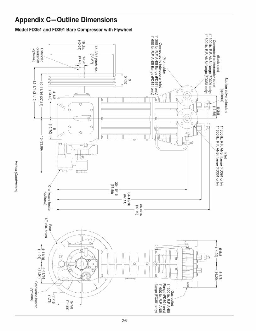
Appendix C—Outline Dimensions
Model FD351 and FD391 Bare Compressor with Flywheel
26
Inc
he
s (C
en
timete
rs)
1478
1302
CO
RK
EN
,INC
.
03
21
PSI
KG/C
M¬
010
2030
40
OIL
42
22
-X
OU
TLE
TIN
LET
Suctio
n v
alv
e
unlo
ad
ers
(op
tional)
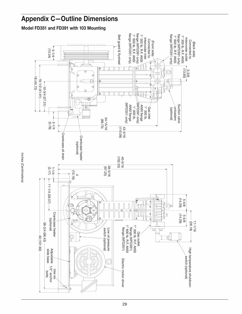
Belt g
uard
& fl
yw
heel
Cra
nkcase h
eate
r
(op
tional)
Cra
nkcase o
il dra
in
Hig
h te
mp
era
ture
shutd
ow
n
sw
itch (o
ptio
nal)
Ele
ctric
mo
tor d
river
Use s
ix
1/2
" ancho
r
bo
lts
Ad
justa
ble
slid
e b
ase
Lo
w o
il pre
ssure
sw
itch (o
ptio
nal)
Cra
nkcase h
eate
r
(op
tional)
5-3
/8
(13.6
5)
43-5
/16
(110.0
9)
34-1
5/1
6
(88.7
5)
2-1
/4
(5.7
8)
10-3
/4 (2
7.3
1)
16-1
/2 (4
1.9
1)
18 (4
5.7
2)
40-5
/16
(102.3
3)38-5
/16
(97.2
5)
5-5
/8
(14.2
9)
5-5
/8
(14.2
9)
11-1
/16
(28.1
8)
1-1
/4
(3.1
7)
11-1
/4 (2
8.5
7)
38-3
/4 (9
8.4
3)
40 (1
01.6
0)
4
(10.1
6)
5-1
/4
(13.3
4)
(Back s
ide)
Co
nnecte
d to
inte
rco
ole
r outle
t
1" 3
00 lb
. R.F. A
NS
I
flang
e (W
FD
391 o
nly
)
1" 6
00 lb
. R.F. A
NS
I
flang
e (W
FD
351 o
nly
)
Gas o
utle
t
1" 3
00 lb
. R.F. A
NS
I
flang
e (W
FD
391)
1" 6
00 lb
. R.F. A
NS
I
flang
e (W
FD
351)
(Fro
nt s
ide)
Co
nnecte
d to
inte
rco
ole
r inle
t
1" 3
00 lb
. R.F. A
NS
I
flang
e (W
FD
391 o
nly
)
1" 6
00 lb
. R.F. A
NS
I
flang
e (W
FD
351 o
nly
)
Gas in
let
1" 3
00 lb
.
AN
SI fl
ang
e
(WF
D391 o
nly
)
1" 6
00 lb
.
AN
SI fl
ang
e
(WF
D351 o
nly
)
Appendix C—Outline Dimensions
Model FD351 and FD391 with 103 Mounting
29
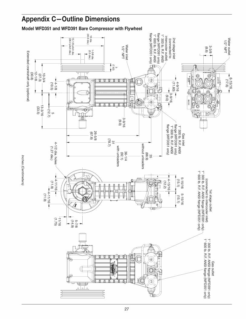
Wate
r outle
t
1/2
" NP
T
3-3
/8
(8.6
)
6-1
5/1
6
(17.6
)
4-9
/16
(11.6
0)
3-9
/16
(9.0
)
Wate
r inle
t
1/2
" NP
T
1-3
/8 d
ia.
(3.5
dia
.)16 d
ia.
(40.6
dia
.)
15-1
/8 p
itch d
ia.
(38.4
pitc
h d
ia.)
4-1
/8
(10.5
)
10-3
/4
(27.3
)
12-1
/8
(30.8
)
Exte
nd
ed
cra
nkshaft o
nly
(op
tional)
5
(12.7
)
13-3
/16
(33.5
)
4-1
/2 d
ia. h
ole
s
(1.2
7 d
ia.)
26-5
/8
(67.6
)
31
(78.7
)
3-9
/16
(9.0
)
35
(88.9
)
with
out u
nlo
ad
ers
36-1
/4
(92.1
)
with
unlo
ad
ers
4-1
1/1
6
(11.9
)
5-1
5/1
6
(15.1
)
4-1
3/1
6
(12.2
)
5-1
5/1
6
(15.1
)
5-7
/8
(14.9
)
11/1
6
(1.7
5)
3
(7.6
2)
4-1
1/1
6
(11.9
)
Gas in
let
1" 3
00 lb
. R.F. A
NS
I
flang
e (W
FD
391 o
nly
)
1" 6
00 lb
. R.F. A
NS
I
flang
e (W
FD
351 o
nly
)
2nd
sta
ge in
let
(co
nnecte
d to
inte
rco
ole
r outle
t)
1" 3
00 lb
. R.F. A
NS
I
flang
e (W
FD
391 o
nly
)
1" 6
00 lb
. R.F. A
NS
I
flang
e (W
FD
351 o
nly
)
1st s
tag
e o
utle
t
(co
nnecte
d to
inte
rco
ole
r inle
t)
1" 3
00 lb
. R.F. A
NS
I flang
e (W
FD
391 o
nly
)
1" 6
00 lb
. R.F. A
NS
I flang
e (W
FD
351 o
nly
)
Gas o
utle
t
1" 3
00 lb
. R.F. A
NS
I flang
e (W
FD
391 o
nly
)
1" 6
00 lb
. R.F. A
NS
I flang
e (W
FD
351 o
nly
)
Inc
he
s (C
en
timete
rs)
Appendix C—Outline Dimensions
Model WFD351 and WFD391 Bare Compressor with Flywheel
27
Inc
he
s (C
en
timete
rs)
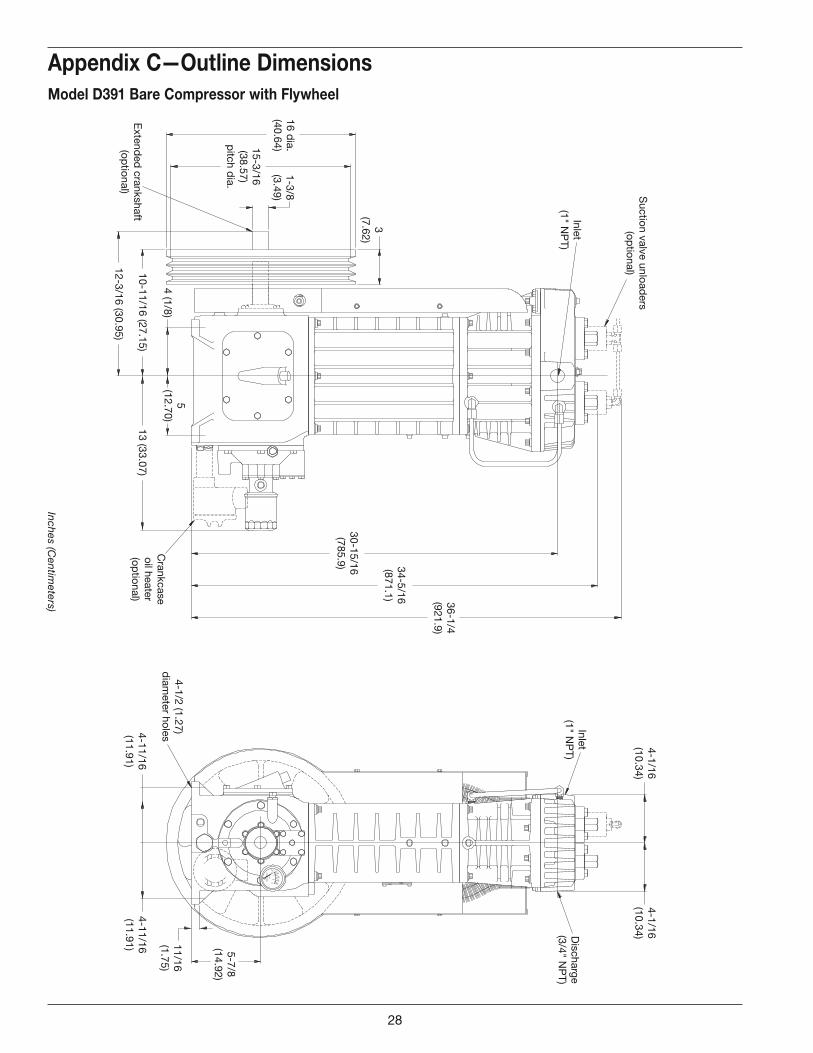
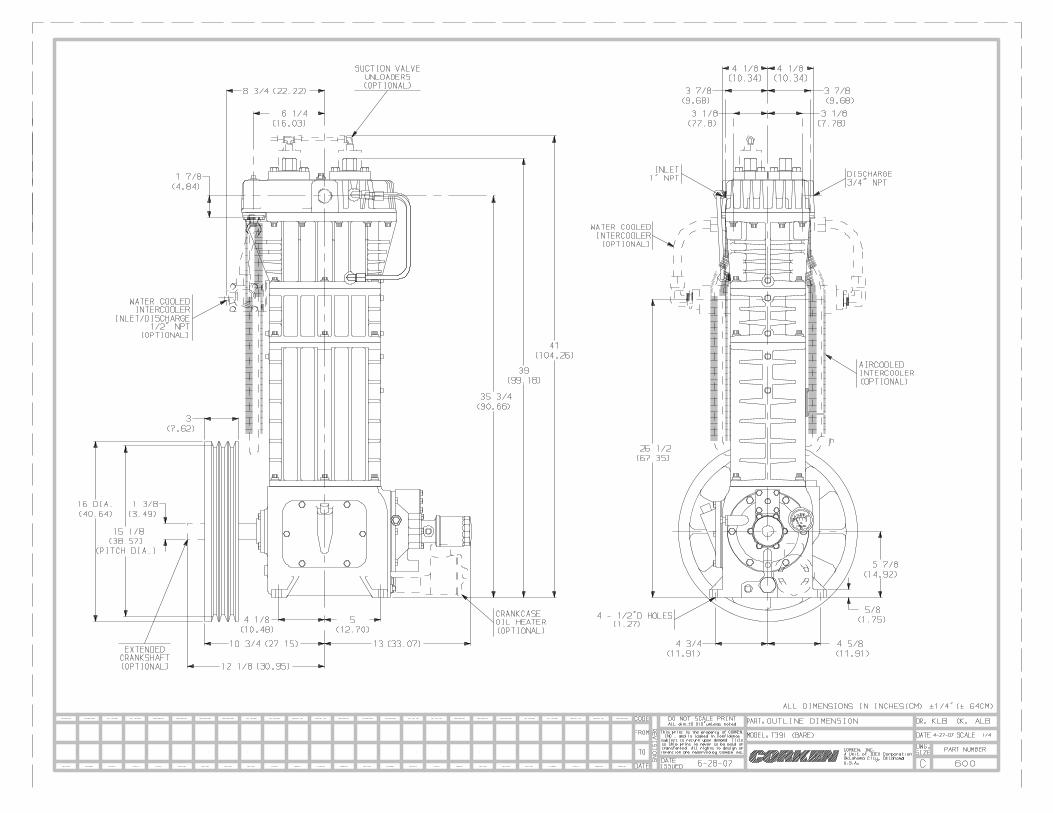
Appendix C—Outline Dimensions
Model D391 Bare Compressor with Flywheel
CO
RK
EN
,INC
.
03
21
PSI
KG/C
M¬
010
2030
40
OIL
3/8Tx1/4P1991
14871488
Suctio
n v
alv
e u
nlo
ad
ers
(op
tional)
3
(7.6
2)
16 d
ia.
(40.6
4)
1-3
/8
(3.4
9)
15-3
/16
(38.5
7)
pitc
h d
ia.
Exte
nd
ed
cra
nkshaft
(op
tional)
10-1
1/1
6 (2
7.1
5)
12-3
/16 (3
0.9
5)
Cra
nkcase
oil h
eate
r
(op
tional)
4-1
/2 (1
.27)
dia
mete
r ho
les
36-1
/4
(921.9
)
5-7
/8
(14.9
2)
34-5
/16
(871.1
)
30-1
5/1
6
(785.9
)
Inle
t
(1" N
PT
)
4-1
/16
(10.3
4)
4-1
/16
(10.3
4)D
ischarg
e
(3/4
" NP
T)
13 (3
3.0
7)
5
(12.7
0)
4 (1
/8)
11/1
6
(1.7
5)
4-1
1/1
6
(11.9
1)
4-1
1/1
6
(11.9
1)
Inle
t
(1" N
PT
)
28
03
21
010
2030
40
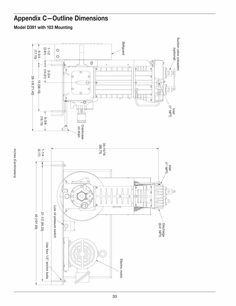
Beltg
uard
1-1
/2
(3.8
1)
28-1
/8 (7
1.4
0)
Cra
nkcase
oil d
rain
34-1
5/1
6
(88.7
5)
1-1
/4
(3.1
7)
37-1
/2 (9
5.2
5)
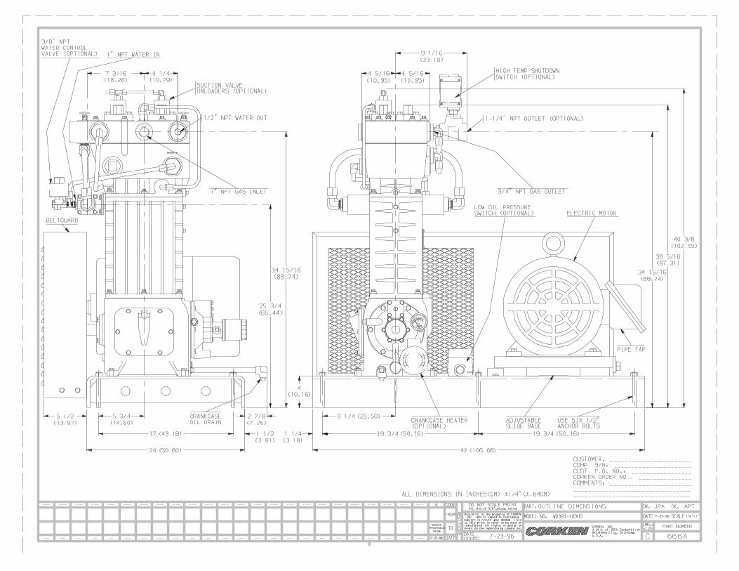
Use fo
ur 1
/2" a
ncho
r bo
lts
Lo
w o
il pre
ssure
sw
itch
Ele
ctric
mo
tor
6-3
/4
(17.1
5)
5-3
/4
(14.6
1)
15 (3
8.1
0)
6-3
/8
(16.1
5)
40 (1
01.6
0)
Dis
charg
e
(3/4
" NP
T)
Inle
t
(1" N
PT
)
Suctio
n v
alv
e u
nlo
ad
ers
(op
tional)
Inle
t
(1" N
PT
)
Inc
he
s (C
en
timete
rs)
Appendix C—Outline Dimensions
Model D391 with 103 Mounting
30
D
C
B
AA
B
C
D
12345678
8 7 6 5 4 3 2 1
E
F
E
F
APPROVALS: DATE:
DRAWN BY:
CHECKED BY:
RESP. ENG.
MATERIAL:
SCALE: SHEET
SIZE: REV.
C
CORKEN ®
CORKEN, INC.A Unit of IDEX CorparationOklahoma City, Oklahoma U.S.A.
DO NOT SCALE DRAWING
This print is the property of
CORKEN, INC., and is loaned in
confidence subject to return
upon demand. Title to this print
is never to be sold or
transfered. All rights to design
or invention are reserved by
CORKEN, INC.
MODEL:
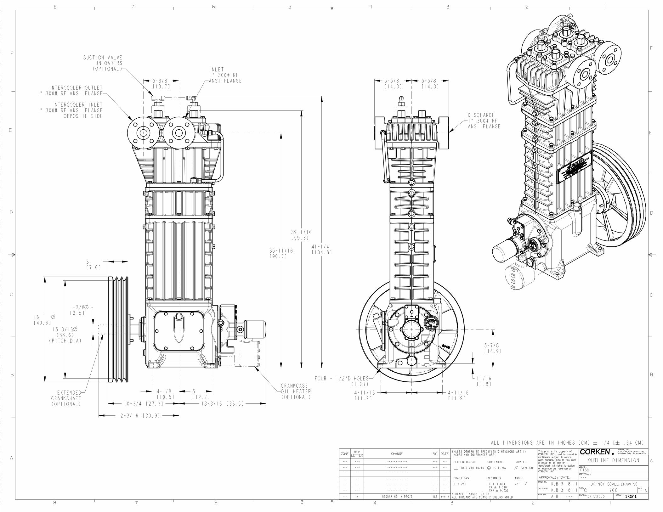
12-3/16 [30.9]
3[7.6]
16[40.6]
15 3/16(38.6)
(PITCH DIA)
1-3/8[3.5]
4-1/8[10.5]
5[12.7]
10-3/4 [27.3] 13-3/16 [33.5]
35-11/16[90.7]
39-1/16[99.3]
41-1/4[104.8]
5-3/8[13.7]
5-5/8[14.3]
5-5/8[14.3]
5-7/8[14.9]
4-11/16[11.9]
4-11/16[11.9]
11/16[1.8]
OUTLINE DIMENSION
FT391
---
760 A
547/2500 1 OF 1
KLB 3-18-11
KLB 3-18-11
ALB ---
UNLESS OTHERWISE SPECIFIED DIMENSIONS ARE ININCHES AND TOLERANCES ARE:
PERPENDICULAR CONCENTRIC PARALLEL
TO 0.010 IN/IN TO 0.250 TO 0.250
FRACTIONS DECIMALS ANGLE
�# 0.250 .X �# 1.000.XX �# 0.500.XXX �# 0.250
�# 5�$
SURFACE FINISH: 125 RaALL THREADS ARE CLASS 2 UNLESS NOTED
ZONEREV
LETTERCHANGE BY DATE
--- --- ------------ --- ---
--- --- ------------ --- ---
--- --- ------------ --- ---
--- --- ------------ --- ---
--- --- ------------ --- ---
--- --- ------------ --- ---
--- A REDRAWING IN PRO/E KLB 3-18-11
EXTENDEDCRANKSHAFT(OPTIONAL)
DISCHARGE1" 300# RFANSI FLANGE
FOUR - 1/2"D HOLES(1.27)CRANKCASE
OIL HEATER(OPTIONAL)
INTERCOOLER OUTLET1" 300# RF ANSI FLANGE
INTERCOOLER INLET1" 300# RF ANSI FLANGE
OPPOSITE SIDE
SUCTION VALVEUNLOADERS
(OPTIONAL) INLET1" 300# RFANSI FLANGE


![Section 4 Flanges - aapindustries.com.au · 69 FLANGES [4] ANSI C150 NPT Screwed Flange ANSI B16.5 C150 NPT Screwed Flange AAP CoDE IMPERIAL SIZE A B D E F H J BoLT SIZE](https://img.pdfslide.us/doc/110x75/5b8c10a809d3f24a638c563f/section-4-flanges-69-flanges-4-ansi-c150-npt-screwed-flange-ansi-b165-c150.jpg)