Embed Size (px)
Citation preview
APPENDIX CAIr & MultIPurPosE General Purpose Heavy Duty Push-on ChEMICAl trANsfEr ClEANINg EquIPMENt fooD Transfer Washdown MArINE MAtErIAl hANDlINg Abrasives Bulk Transfer Cement & Concrete MININg PEtrolEuM Aircraft Fueling Dispensing Dock Transfer sPrAy stEAM VACuuM VEyANCE WAtEr Discharge Suction & Discharge Washdown WElDINg CouPlINg systEMs APPENDIX
298
CHEMICAL PROPERTIES Of fLUROETHyLENEPROPyLENE (fEP)
METHOD fOR STEAM CLEANING GOODyEAR ENGINEERED PRODUCTS (CHEM ONE, VIPER, fAbCHEM AND fAbCHEM ARC)
AS STATED by E.I. DU PONT DE NEMOURS
5 IMPORTANT REQUIREMENTS
GENERAL INFORMATION
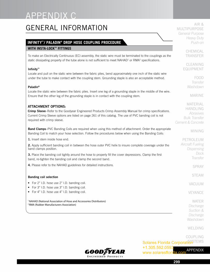
FEP fluorocarbon resins are attacked by certain halogenated complexes containing fluorine including: chlorine trifluoride, bromine trifluoride, iodine pentafluoride and fluorine itself.
FEP is also attacked by such metals as sodium or potassium, especially in their molten states. Great care should be used when mixing finely divided fluorocarbon polymers with finely divided metals, such as aluminum, magnesium or barium, since these can react violently if ignited or heated to a high temperature. Certain complexes of these metals with ammonia or naphthalene (in either solvent) also attack the products. Certain metal hydrides such as boranes, aluminum chloride and certain amines have also been observed to attack fluorocarbon resins at elevated temperatures.
The following materials are inert to FEP:
Alcohols Aldehydes Aliphatic Hydrocarbons Anhydrides Aromatics Chlorocarbons Esters Ethers Fluorocarbons Inorganic Bases Inorganic Oxidizing Agents Ketones Organic Acids Salt Solutions Strong Mineral Acids
FEP is a registered trademark with E.I. du Pont de Nemours.
1) Hose must be open-ended during steam cleaning.
2) Temperature of Steam–Maximum 288˚F.
3) Length of Cleaning Time–5 to 10 minutes...Not more than 15 minutes.
4) Care must be taken not to score the tube (liner) with the nozzle or wand end.
5) Prolonged steam jet contact on a specific area of the tube (liner) could cause tube damage.
Solares Florida Corporation +1.305.592.0593 www.solaresflorida.com
APPENDIX cAIr &
MultIPurPosE General Purpose
Heavy Duty Push-on
chEMIcAl trANsfEr
clEANINg
EquIPMENt
fooD Transfer
Washdown
MArINE
MAtErIAl hANDlINg
Abrasives Bulk Transfer
Cement & Concrete
MININg
PEtrolEuM Aircraft Fueling
Dispensing Dock
Transfer
sPrAy
stEAM
VAcuuM
VEyANcE
WAtEr Discharge Suction & Discharge
Washdown
WElDINg
couPlINg systEMs
APPENDIX
299
INfINITy™/ PALADIN® DROP HOSE COUPLING PROCEDURE WITH INSTA-LOCk™ fITTINGS
GENERAL INFORMATION
To make an Electrically Continuous (EC) assembly, the static wire must be terminated to the couplings as the static dissipating property of the tube alone is not sufficient to meet NAHAD1 or RMA2 specifications.
Infinity™ Locate and pull on the static wire between the fabric plies, bend approximately one inch of the static wire under the tube to make contact with the coupling stem. Grounding staple is also an acceptable method.
Paladin®
Locate the static wire between the fabric plies. Insert one leg of a grounding staple in the middle of the wire. Ensure that the other leg of the grounding staple is in contact with the coupling stem.
ATTACHMENT OPTIONS:Crimp Sleeve–Refer to the Goodyear Engineered Products Crimp Assembly Manual for crimp specifications. Current Crimp Sleeve options are listed on page 261 of this catalog. The use of PVC banding coil is not required with crimp sleeve.
Band Clamps–PVC Banding Coils are required when using this method of attachment. Order the appropriate Banding Coil to match your hose selection. Follow the procedures below when using the Banding Coils:
1. Insert stem inside hose end.
2. Apply sufficient banding coil in between the hose outer PVC helix to insure complete coverage under the band clamps position.
3. Place the banding coil tightly around the hose to properly fill the cover depressions. Clamp the first band, re-tighten the banding coil and clamp the second band.
4. Please refer to the NAHAD guidelines for detailed instructions.
Banding coil selection
• For2’’I.D.hoseuse2’’I.D.bandingcoil.• For3’’I.D.hoseuse3’’I.D.bandingcoil.• For4’’I.D.hoseuse4’’I.D.bandingcoil.
1 NAHAD (National Association of Hose and Accessories Distributors)2 RMA (Rubber Manufacturers Association)
Solares Florida Corporation +1.305.592.0593 www.solaresflorida.com
APPENDIX CAIr & MultIPurPosE General Purpose Heavy Duty Push-on ChEMICAl trANsfEr ClEANINg EquIPMENt fooD Transfer Washdown MArINE MAtErIAl hANDlINg Abrasives Bulk Transfer Cement & Concrete MININg PEtrolEuM Aircraft Fueling Dispensing Dock Transfer sPrAy stEAM VACuuM VEyANCE WAtEr Discharge Suction & Discharge Washdown WElDINg CouPlINg systEMs APPENDIX
300
D
Type 1
Type 2
D
•
TyPE 1: Vertical Braided HoseEntire hose length cured in one operation.
A. Extruded seamless tube.B. Seamless reinforcing braids of synthetic textile wire, or other material – applied by high speed vertical or horizontal braiders.C. Rubber layers between braids establish positive bond between braids when vulcanized. D. Extruded, seamless cover.
AbC
TyPE 2: Spiral Hose Built by machine with either textile or wire cord reinforcement applied so that each ply is laid at a given angle for maximum dimensional stability.
A. Extruded or calendered tube.B. Reinforcement of synthetic textile wire or other material.C. Rubber layers between reinforcement plies to establish positive bond. D. Cover.
AbC
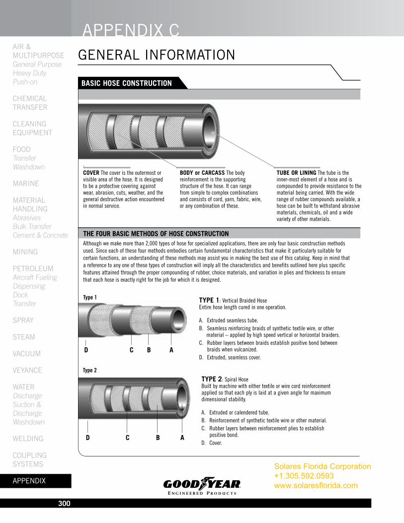
bASIC HOSE CONSTRUCTION
GENERAL INFORMATION
THE fOUR bASIC METHODS Of HOSE CONSTRUCTIONAlthough we make more than 2,000 types of hose for specialized applications, there are only four basic construction methods used. Since each of these four methods embodies certain fundamental characteristics that make it particularly suitable for certain functions, an understanding of these methods may assist you in making the best use of this catalog. Keep in mind that a reference to any one of these types of construction will imply all the characteristics and benefits outlined here plus specific features attained through the proper compounding of rubber, choice materials, and variation in plies and thickness to ensure that each hose is exactly right for the job for which it is designed.
COVER The cover is the outermost or visible area of the hose. It is designed to be a protective covering against wear, abrasion, cuts, weather, and the general destructive action encountered in normal service.
bODy or CARCASS The body reinforcement is the supporting structure of the hose. It can range from simple to complex combinations and consists of cord, yarn, fabric, wire, or any combination of these.
TUbE OR LINING The tube is the inner-most element of a hose and is compounded to provide resistance to the material being carried. With the wide range of rubber compounds available, a hose can be built to withstand abrasive materials, chemicals, oil and a wide variety of other materials.
• •
Solares Florida Corporation +1.305.592.0593 www.solaresflorida.com

APPENDIX cAIr &
MultIPurPosE General Purpose
Heavy Duty Push-on
chEMIcAl trANsfEr
clEANINg
EquIPMENt
fooD Transfer
Washdown
MArINE
MAtErIAl hANDlINg
Abrasives Bulk Transfer
Cement & Concrete
MININg
PEtrolEuM Aircraft Fueling
Dispensing Dock
Transfer
sPrAy
stEAM
VAcuuM
VEyANcE
WAtEr Discharge Suction & Discharge
Washdown
WElDINg
couPlINg systEMs
APPENDIX
301
TyPE 4: Knitted Hose
A. Extruded seamless tube.B. Seamless woven textile jacket.C. Interwoven wire helix reinforcement where needed.D. Extruded seamless cover.
ACbD
Type 4
TyPE 3: Hand-built Spiral-plied HoseBuilt by hand on a mandrel. Cured under pressure applied from outside by cloth wraps and steam.
A. Calendered, or “built-up” tube to fit service.B. Tailor-made spiral-wrapped fabric.C. Wire reinforcement where needed. D. Cover stock of selected gauge and compound. Wrap cured.
AbCD
Type 3
bASIC HOSE CONSTRUCTION
GENERAL INFORMATION
TyPE 1 braided HoseFlexible. High resistance to kinking. Cover either smooth or wrapped. Available in long continuous lengths. Excellent tensile strength.
TyPE 2 Spiral HoseExtremely flexible. Smooth bore, uniform tube. High strength with long length capability.
TyPE 3 Hand-built Spiral-Plied HoseCraftsman-built to special requirements. Wide variation in sizes, constructions and materials. Built-in strength to fit most rugged job requirements. Couplings, fittings, nipples, flanges and beaded ends can be built in. Available in lengths up to 50 feet, in sizes up to 18 inches. On larger diameters, consult your Goodyear Engineered Products representative.
THE fOUR bASIC METHODS Of HOSE CONSTRUCTION (continued)
ADVANTAGES
Solares Florida Corporation +1.305.592.0593 www.solaresflorida.com
APPENDIX CAIr & MultIPurPosE General Purpose Heavy Duty Push-on ChEMICAl trANsfEr ClEANINg EquIPMENt fooD Transfer Washdown MArINE MAtErIAl hANDlINg Abrasives Bulk Transfer Cement & Concrete MININg PEtrolEuM Aircraft Fueling Dispensing Dock Transfer sPrAy stEAM VACuuM VEyANCE WAtEr Discharge Suction & Discharge Washdown WElDINg CouPlINg systEMs APPENDIX
302
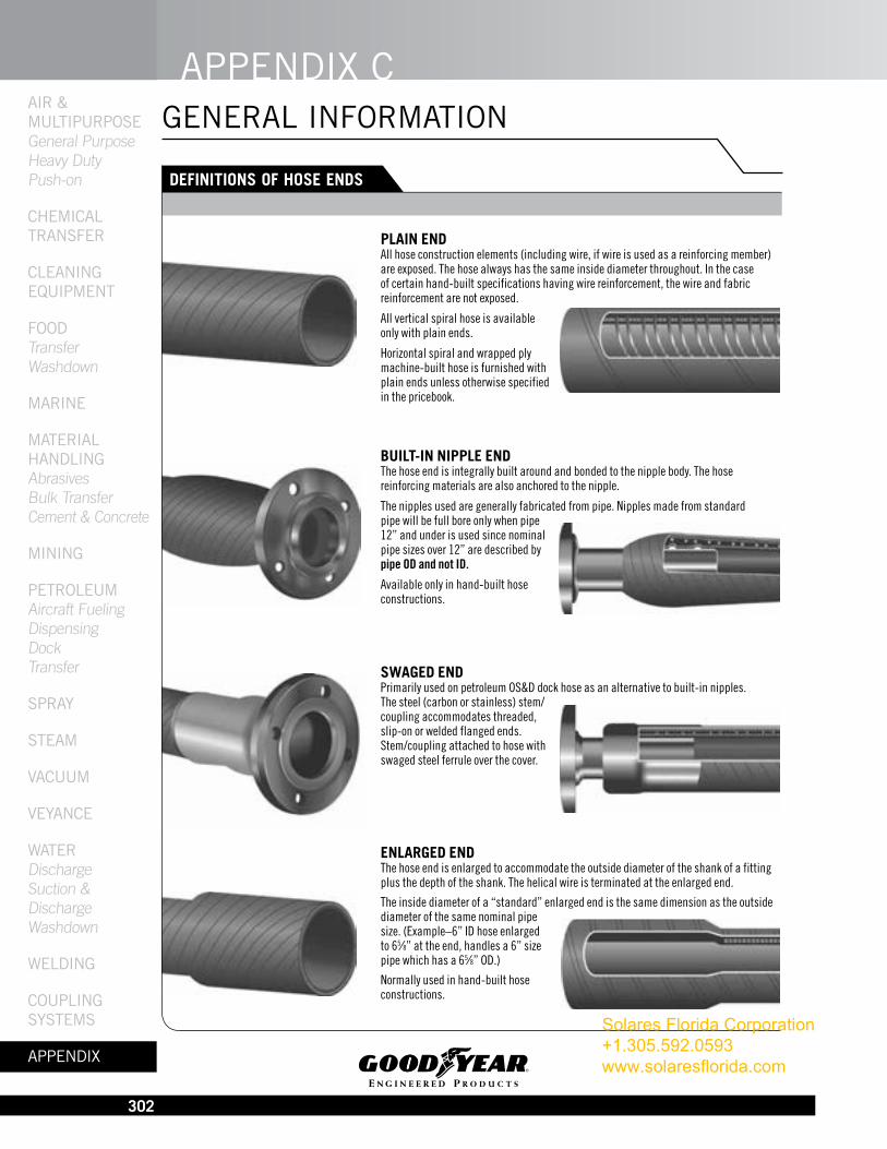
PLAIN END All hose construction elements (including wire, if wire is used as a reinforcing member) are exposed. The hose always has the same inside diameter throughout. In the case of certain hand-built specifications having wire reinforcement, the wire and fabric reinforce ment are not exposed.
All vertical spiral hose is available only with plain ends.
Horizontal spiral and wrapped ply machine-built hose is furnished with plain ends unless otherwise specified in the pricebook.
bUILT-IN NIPPLE ENDThe hose end is integrally built around and bonded to the nipple body. The hose reinforcing materials are also anchored to the nipple.
The nipples used are generally fabricated from pipe. Nipples made from standard pipe will be full bore only when pipe 12” and under is used since nominal pipe sizes over 12” are described by pipe OD and not ID.
Available only in hand-built hose constructions.
SWAGED END Primarily used on petroleum OS&D dock hose as an alternative to built-in nipples. The steel (carbon or stainless) stem/coupling accommodates threaded, slip-on or welded flanged ends. Stem/coupling attached to hose with swaged steel ferrule over the cover.
ENLARGED END The hose end is enlarged to accommodate the outside diameter of the shank of a fitting plus the depth of the shank. The helical wire is terminated at the enlarged end.
The inside diameter of a “standard” enlarged end is the same dimension as the outside diameter of the same nominal pipe size. (Example–6” ID hose enlarged to 65⁄8” at the end, handles a 6” size pipe which has a 65⁄8” OD.)
Normally used in hand-built hose constructions.
DEfINITIONS Of HOSE ENDS
GENERAL INFORMATION
Solares Florida Corporation +1.305.592.0593 www.solaresflorida.com
APPENDIX cAIr &
MultIPurPosE General Purpose
Heavy Duty Push-on
chEMIcAl trANsfEr
clEANINg
EquIPMENt
fooD Transfer
Washdown
MArINE
MAtErIAl hANDlINg
Abrasives Bulk Transfer
Cement & Concrete
MININg
PEtrolEuM Aircraft Fueling
Dispensing Dock
Transfer
sPrAy
stEAM
VAcuuM
VEyANcE
WAtEr Discharge Suction & Discharge
Washdown
WElDINg
couPlINg systEMs
APPENDIX
303
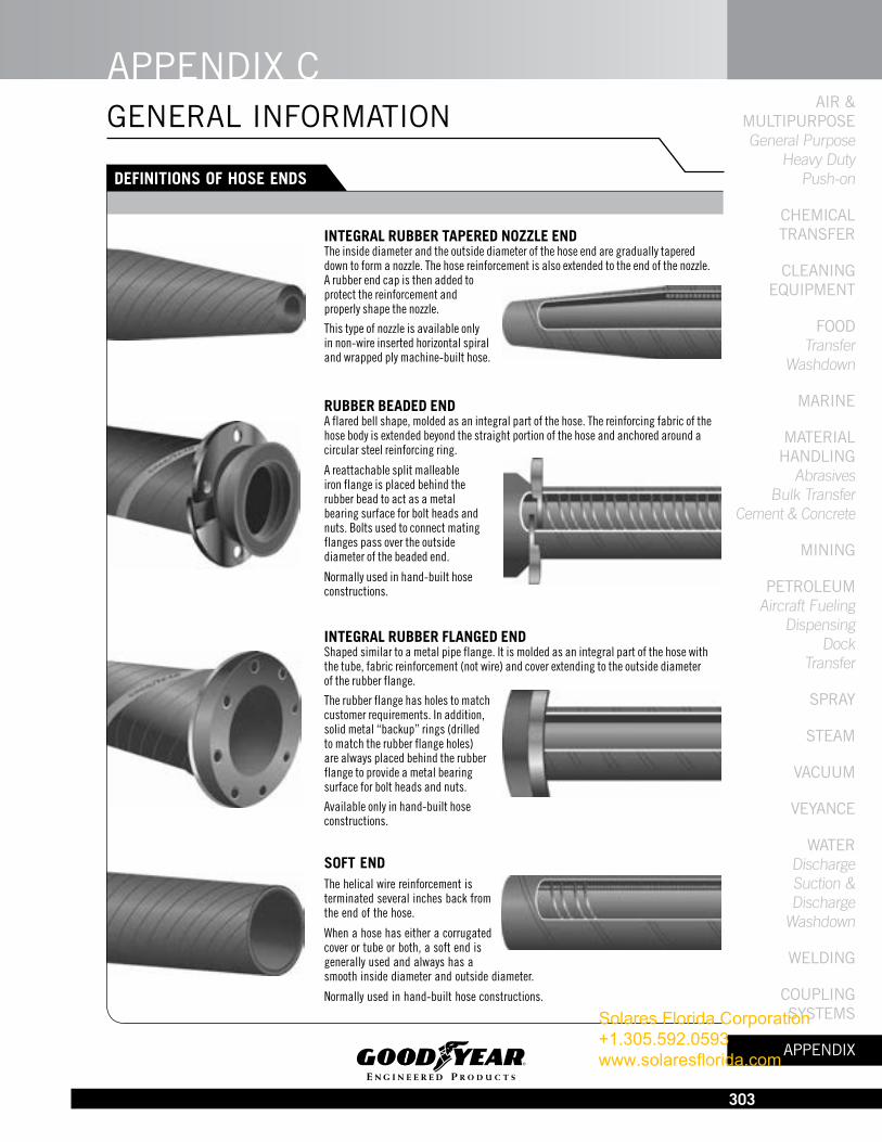
INTEGRAL RUbbER TAPERED NOzzLE END The inside diameter and the outside diameter of the hose end are gradually tapered down to form a nozzle. The hose reinforcement is also extended to the end of the nozzle. A rubber end cap is then added to protect the reinforcement and properly shape the nozzle.
This type of nozzle is available only in non-wire inserted horizontal spiral and wrapped ply machine-built hose.
RUbbER bEADED END A flared bell shape, molded as an integral part of the hose. The reinforcing fabric of the hose body is extended beyond the straight portion of the hose and anchored around a circular steel reinforcing ring.
A reattachable split malleable iron flange is placed behind the rubber bead to act as a metal bearing surface for bolt heads and nuts. Bolts used to connect mating flanges pass over the outside diameter of the beaded end.
Normally used in hand-built hose constructions.
INTEGRAL RUbbER fLANGED END Shaped similar to a metal pipe flange. It is molded as an integral part of the hose with the tube, fabric reinforcement (not wire) and cover extending to the outside diameter of the rubber flange.
The rubber flange has holes to match customer requirements. In addition, solid metal “backup” rings (drilled to match the rubber flange holes) are always placed behind the rubber flange to provide a metal bearing surface for bolt heads and nuts.
Available only in hand-built hose constructions.
SOfT END The helical wire reinforcement is terminated several inches back from the end of the hose.
When a hose has either a corrugated cover or tube or both, a soft end is generally used and always has a smooth inside diameter and outside diameter.
Normally used in hand-built hose constructions.
DEfINITIONS Of HOSE ENDS
GENERAL INFORMATION
Solares Florida Corporation +1.305.592.0593 www.solaresflorida.com
APPENDIX CAIr & MultIPurPosE General Purpose Heavy Duty Push-on ChEMICAl trANsfEr ClEANINg EquIPMENt fooD Transfer Washdown MArINE MAtErIAl hANDlINg Abrasives Bulk Transfer Cement & Concrete MININg PEtrolEuM Aircraft Fueling Dispensing Dock Transfer sPrAy stEAM VACuuM VEyANCE WAtEr Discharge Suction & Discharge Washdown WElDINg CouPlINg systEMs APPENDIX
304
HOSE TESTING METHODS
HyDROSTATIC PRESSURE TESTS
SAfETy WARNING:
Testing can be dangerous and should be done only by trained personnel using proper tools and procedures. failure to follow such procedures might result in damage to property and/or serious bodily injury.
GENERAL INFORMATION
The Rubber Manufacturers Association (RMA) recognizes, accepts and recommends the testing methods of the American Society for Testing and Materials (ASTM).
Unless otherwise specified, all hose tests are to be conducted in accordance with ASTM Method No. D-380 (latest revision). Where an ASTM D-380 test is not available, another test method should be selected and described in detail.
RMA participates with ASTM under the auspices of the American National Standards Institute (ANSI) in Technical Committee 45 (TC45) of The International Organization for Standardization (ISO) in developing both hose product and hose test method standards. Many of the hose test method standards published by ISO duplicate or closely parallel those shown in ASTM D-380. Many are unique and, in those cases, the RMA may be able to provide the necessary test standard references which may be purchased from the American National Standards Institute (ANSI).
Reprinted from RMA hose handbook IP-2 2003
HyDROSTATIC PRESSURE TESTS ARE CLASSIfIED AS fOLLOWS:1. DESTRUCTIVE TYPE a. Burst test b. Hold test
Destructive TestsDestructive tests are conducted on short specimens of hose, normally 18 inches (460 mm) to 36 inches (915 mm) in length and, as the name implies, the hose is destroyed in the performance of the test. a. Burst pressure is recorded as the pressure at which actual rupture of a hose occurs. b. A hold test, when required, is a means of determining whether weakness will develop under a given pressure for a specified period of time.
2. NON-DESTRUCTIVE TYPE a. Proof pressure test c. Change in outside diameter e. Rise test h. Volumetric expansion test b. Change in length test or circumference test f. Twist test (elongation or contraction) d. Warp test g. Kink test
Non-Destructive TestsNon-destructive tests are conducted on a full length of a hose or hose assembly. These tests are for the purpose of eliminating hose with defects which cannot be seen by visual examination or in order to determine certain characteristics of the hose while it is under internal pressure. a. A proof pressure test is normally applied to hose for a specified period of time. On new hose, the proof pressure is usually 50% of the minimum specified burst except for woven jacket fire hose where the proof pressure is twice the service test pressure marked on the hose (67% of specified minimum burst). Hydrostatic tests performed on fire hose in service should be no higher than the service test pressure referred to above. The regulation of these pressures is extremely important so that no deteriorating stresses will be applied, thus weakening a normal hose.
b. With some type of hose, it is useful to know how a hose will act under pressure. All change in length tests, except when performed on wire braid or wire spiralled hose, are made with original length measurements taken under a pressure of 10 psi (0.069 MPa). The specified pressure, which is normally the proof pressure, is applied and immediate measurement of the characteristics desired are taken and recorded.
Solares Florida Corporation +1.305.592.0593 www.solaresflorida.com
APPENDIX cAIr &
MultIPurPosE General Purpose
Heavy Duty Push-on
chEMIcAl trANsfEr
clEANINg
EquIPMENt
fooD Transfer
Washdown
MArINE
MAtErIAl hANDlINg
Abrasives Bulk Transfer
Cement & Concrete
MININg
PEtrolEuM Aircraft Fueling
Dispensing Dock
Transfer
sPrAy
stEAM
VAcuuM
VEyANcE
WAtEr Discharge Suction & Discharge
Washdown
WElDINg
couPlINg systEMs
APPENDIX
305
HOSE TESTING METHODS
GENERAL INFORMATION
HyDROSTATIC PRESSURE TESTS (continued): Percent length change (elongation or contraction) is the difference between the length at 10 psi (0.069 MPa) (except wire braided or wire spiralled) and that at the proof pressure times 100 divided by the length at 10 psi (0.069 MPa). Elongation occurs if the length of the hose under the proof pressure is greater than at a pressure of 10 psi (0.069 MPa). Contraction occurs if the length at the proof pressure is less than at 10 psi (0.069 MPa). In testing wire braided or spiralled hose, the proof pressure is applied and the length recorded. The pressure is then released and, at the end of 30 seconds, the length is measured; the measurement obtained is termed the “original length.”
c. Percent change in outside diameter or circumference is the difference between the outside diameter or circumference at 10 psi (0.069 MPa) and that obtained under the proof pressure times 100 divided by the outside diameter or circumference at 10 psi (0.069 MPa). Expansion occurs if the measurement at the proof pressure is greater than at 10 psi (0.069 MPa). Contraction occurs if the measurement at the proof pressure is less than at 10 psi (0.069 MPa).
d. Warp is the deviation from a straight line drawn from fitting to fitting; the maximum deviation from this line is warp. First, a measurement is taken at 10 psi (0.069 MPa) and then again at the proof pressure. The difference between the two, in inches, is the warp. Normally this is a feature measured on woven jacket fire hose only.
e. Rise is a measure of the height a hose rises from the surface of the test table while under pressure. The difference between the rise at 10 psi (0.069 MPa) and at the proof pressure is reported to the nearest 0.25 inch (6.4 mm). Normally, this is a feature measured on woven jacket fire hose only.
f. Twist is a rotation of the free end of the hose while under pressure. A first reading is taken at 10 psi (0.069 MPa) and a second reading at proof pressure. The difference, in degrees, between the 10 psi (0.069 MPa) base and that at the proof pressure is the twist. Twist is reported as right twist (to tighten couplings) or left twist. Standing at the pressure inlet and looking toward the free end of a hose, a clockwise turning is right twist and counterclockwise is left twist.
g. Kink test is a measure of the ability of woven jacket hose to withstand a momentary pressure while the hose is bent back sharply on itself at a point approximately 18 inches (457 mm) from one end. Test is made at pressures ranging from 62% of the proof pressure on sizes 3 inches (76 mm) and 3.5 inches (89 mm) to 87% on sizes under 3 inches (76 mm). This is a test applied to woven jacket fire hose only.
h. Volumetric expansion test is applicable only to specific types of hose, such as hydraulic or power steering hose, and is a measure of its volumetric expansion under ranges of internal pressure.
DESIGN CONSIDERATIONSIn designing hose, it is customary to develop a design ratio, which is a ratio between the minimum burst and the maximum working pressure.
Burst test data is compiled and the minimum value is established by accepted statistical techniques. This is done as a check ontheoretical calculations, based on the strength of reinforcing materials and on the characteristics of the method of fabrication.
Minimum burst values are used as one factor in the establishment of a reasonable and safe maximum working pressure.
MAXIMUM WORKING PRESSURE IS ONE OF THE ESSENTIAL OPERATING CHARACTERISTICS THAT A HOSE USER MUST KNOW AND RESPECT TO ASSURE SATISFACTORY SERVICE AND OPTIMUM LIFE.
It should be noted that design ratios are dependent on more than the minimum burst. The hose technologist must anticipate natural decay in strength of reinforcing materials, and the accelerated decay induced by the anticipated environments in which the hose will be used and the dynamic situations that a hose might likely encounter in service.
Including all considerations, the following recommended design ratios are given for newly manufactured hose:
1. Water hose up to 150 psi WP: 3:1
2. Hose for all other liquids, solid materials suspended in liquids or air, and water hose over 150 psi WP: 4:1
3. Hose for compressed air and other gases: 4:1
4. Hose for liquid media that immediately changes into gas under standard atmospheric conditions: 5:1
5. Steam hose: 10:1
Solares Florida Corporation +1.305.592.0593 www.solaresflorida.com
APPENDIX CAIr & MultIPurPosE General Purpose Heavy Duty Push-on ChEMICAl trANsfEr ClEANINg EquIPMENt fooD Transfer Washdown MArINE MAtErIAl hANDlINg Abrasives Bulk Transfer Cement & Concrete MININg PEtrolEuM Aircraft Fueling Dispensing Dock Transfer sPrAy stEAM VACuuM VEyANCE WAtEr Discharge Suction & Discharge Washdown WElDINg CouPlINg systEMs APPENDIX
306
ELECTRICAL RESISTANCE TESTSfOR HOSE AND HOSE ASSEMbLIES
GENERAL INFORMATION
1.0 Purpose: This procedure specifies methods for performing electrical resistance tests on rubber and/or plastic hose and hose assemblies.
2.0 Scope: These procedures are intended to test electrical conductive, antistatic and nonconductive (insulating) hoses, along with electrical continuity or discontinuity between fittings.
3.0 Definitions: 3.1 Antistatic Hose - Antistatic hose constructions are those that are capable of dissipating the static electricity buildup that occurs during the high velocity flow of material through a hose.
3.2 Conductive Hose – Conductive hose constructions are those that are capable of conducting an electrical current.
3.3 Direct Current (DC): Flow of electrical current in one direction at a constant rate.
3.4 Electrical Conductivity: A measure of the ease with which a material is capable of conducting an electrical current. Conductivity = 1/Resistance.
3.5 Electrical Resistance: Property of an object to resist or oppose the flow of an electrical current.
3.6 Non-Conductive (Insulating) Hose: Non-conductive hose constructions are those that resist the flow of electrical current.
3.7 Ohm’s Law: The electrical current, I, is equal to the applied voltage, V, divided by the resistance, R. In practical terms, the higher the electrical resistance at a constant voltage, the lower the electrical current flow through an object.
3.8 Ohm: The amount of resistance that limits the passage of current to one ampere when a voltage of one volt is applied to it.
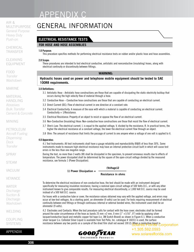
4.0 Apparatus: 4.1 Test Instruments: All test instruments shall have a gauge reliability and reproducibility (R&R) of less than 30%. Some instruments made to measure high electrical resistance may have an internal protection circuit built in which will cause test errors in the less than one megohm range. During the test, no more than 3 watts (W) shall be dissipated in the specimen, to prevent erroneous results due to effects of temperature. The power dissipated shall be determined by the square of the open-circuit voltage divided by the measured resistance, see formula 1 (Power Dissipation).
To determine the electrical resistance of non-conductive hose, the test should be made with an instrument designed specifically for measuring insulation resistance, having a nominal open-circuit voltage of 500 Volts D.C., or with any other instrument known to give comparable results. For measuring electrical discontinuity, a 1,000 Volt D.C. source may be used instead of a 500 Volt D.C. source. For hoses with a conductive tube or cover, the resistance values obtained may vary with the applied voltage, and errors may occur at low-test voltages. As a starting point, an ohmmeter (9 volts) can be used. For tests requiring measurement of electrical continuity between end fittings or through continuous internal or external bonded wires, the instrument used shall be an ohmmeter (9 volts).
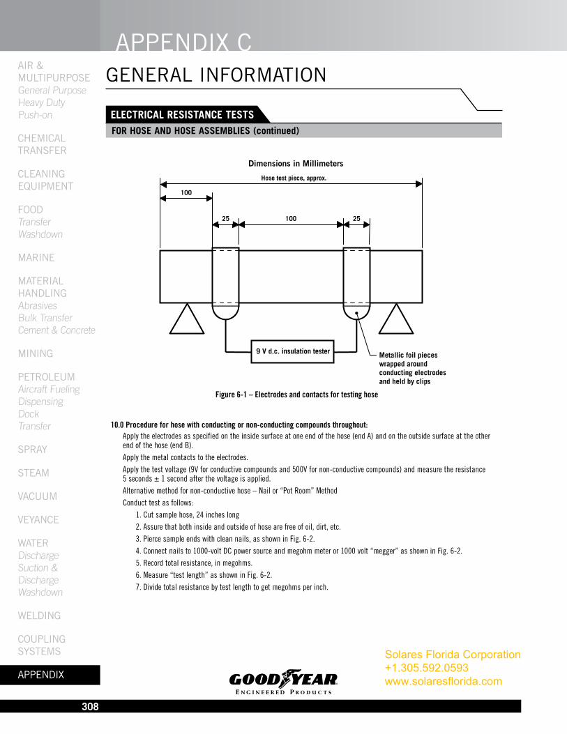
4.2 Electrodes and Contacts: When the test procedure calls for contact with the hose cover, electrodes shall be formed around the outer circumference of the hose as bands 25 mm +2 mm, 0 mm (1” +1/16”, 0”) wide by applying silver lacquer/conductive liquid and metallic copper foil tape (i.e. 3M Scotch Brand) as shown in Figure 6-1. When a conductive silver lacquer (i.e. Colloidal Silver Liquid is available from Ted Pella, Inc. catalogue # 16031) is used, the surface resistance between any two points on a sample of the dried film shall not exceed 100 Ω. When a conductive liquid is
WARNING:
Hydraulic hoses used on power and telephone mobile equipment should be tested to SAE 100R8 requirements.
(Voltage)21) Power Dissipation = Resistance in ohms
Solares Florida Corporation +1.305.592.0593 www.solaresflorida.com
APPENDIX cAIr &
MultIPurPosE General Purpose
Heavy Duty Push-on
chEMIcAl trANsfEr
clEANINg
EquIPMENt
fooD Transfer
Washdown
MArINE
MAtErIAl hANDlINg
Abrasives Bulk Transfer
Cement & Concrete
MININg
PEtrolEuM Aircraft Fueling
Dispensing Dock
Transfer
sPrAy
stEAM
VAcuuM
VEyANcE
WAtEr Discharge Suction & Discharge
Washdown
WElDINg
couPlINg systEMs
APPENDIX
307
ELECTRICAL RESISTANCE TESTSfOR HOSE AND HOSE ASSEMbLIES (continued)
GENERAL INFORMATION
used the electrode contact area shall be completely wetted and shall remain so until the end of the test. The conductive liquid shall consist of:
•Anhydrouspolyethyleneglycolofrelativemolecularmass600:800partsbymass
•Water:200partsbymass
•Wettingagent:1partbymass
•PotassiumChloride:10partsbymass
When the test procedure calls for contact with the hose tube, it is preferable to use a copper plug of external diameter equal to or slightly greater than the hose ID or a steel hose stem, coated with the conducting liquid, and pushed 25 mm (1”) into the hose. An alternative for 50 mm (2”) and above hose would be to apply the conductive silver lacquer onto the hose ID, then insert the plug or hose stem. The electrical leads from the test instrument shall be clean and they should make adequate contact with the metallic copper foil and/or copper plugs/hose stems.
5.0 Preparation and Cleaning for Test: The surfaces of the hose shall be clean. If necessary, the hose surface may be cleaned by rubbing with Fuller’s earth (magnesium aluminum silicate) and water, followed by a distilled water rinse, and allowing the hose to dry in a non- contaminating environment. Do not use organic materials that attack or swell the rubber, and do not buff or abrade the test surfaces. The surface of the hose shall not be deformed either during the application of the contacts or during the test. When using test pieces, the supports shall be outside the test length. When using a long length of hose, the hose shall be uncoiled and laid out straight on polyethylene or other suitable insulating material. Care should be taken to ensure that the hose is insulated from any electrical leakage path along the length of the hose.
6.0 Test Conditions: For lab testing, the hose or hose assemblies shall be conditioned for at least 16 hours at +23° C ± 2°C (73.4°F ± 3.6°F) with a relative humidity not to exceed 70%. However, it is permissible, by agreement between the supplier and the customer, to use the conditions prevailing in the factory, warehouse, or laboratory, provided that the relative humidity does not exceed 70%.
7.0 Test Pieces: Prepare three test pieces approximately 300 mm (12”) long from samples taken at random from a production run or lot. Condition the test pieces per section 6.0. Place the test piece on blocks of polyethylene, or other insulating material, to provide a resistance of greater than 1011 Ω between the test piece and the surface on which the blocks are supported. Ensure that the leads from the instrument do not touch each other, the hose, or any part except the terminal to which each is connected. Avoid breathing on the test surfaces and thus creating condensation that may lead to inaccuracies.
8.0 Procedure for hoses with conducting tube: Apply the electrodes as specified to the inside surface of the hose at each end of the hose. The edge of the electrode plug shall be coincident with the end of the hose. When using a conductive liquid, care shall be taken to avoid creating a leakage path between the tube and the reinforcement or cover of the hose. Apply the metal contacts to the electrodes. Apply the test voltage (9V) and measure the resistance 5 seconds ± 1 second after the voltage is applied. Note: In previous editions of the Hose Handbook, this method was referred to as the Plug Method.
9.0 Procedure for hose with conducting cover: Apply the electrodes as specified to the outer circumference of the hose at each hose end. See Figure 6-1. Ensure that contact is maintained with the electrodes around the circumference and that the contact pieces are sufficiently long enough for the two free ends to be held securely by a tensioning clip (see Figure 6-1) such that the fit of the electrodes is as tight as possible. Apply the metal contacts. Apply the test voltage (9V) and measure the resistance 5 seconds ± 1 second after the voltage is applied.Solares Florida Corporation
+1.305.592.0593 www.solaresflorida.com
APPENDIX CAIr & MultIPurPosE General Purpose Heavy Duty Push-on ChEMICAl trANsfEr ClEANINg EquIPMENt fooD Transfer Washdown MArINE MAtErIAl hANDlINg Abrasives Bulk Transfer Cement & Concrete MININg PEtrolEuM Aircraft Fueling Dispensing Dock Transfer sPrAy stEAM VACuuM VEyANCE WAtEr Discharge Suction & Discharge Washdown WElDINg CouPlINg systEMs APPENDIX
308
ELECTRICAL RESISTANCE TESTSfOR HOSE AND HOSE ASSEMbLIES (continued)
GENERAL INFORMATION
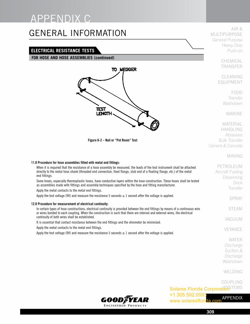
10.0 Procedure for hose with conducting or non-conducting compounds throughout: Apply the electrodes as specified on the inside surface at one end of the hose (end A) and on the outside surface at the other end of the hose (end B). Apply the metal contacts to the electrodes. Apply the test voltage (9V for conductive compounds and 500V for non-conductive compounds) and measure the resistance 5 seconds ± 1 second after the voltage is applied. Alternative method for non-conductive hose – Nail or “Pot Room” Method Conduct test as follows: 1. Cut sample hose, 24 inches long 2. Assure that both inside and outside of hose are free of oil, dirt, etc. 3. Pierce sample ends with clean nails, as shown in Fig. 6-2. 4. Connect nails to 1000-volt DC power source and megohm meter or 1000 volt “megger” as shown in Fig. 6-2. 5. Record total resistance, in megohms. 6. Measure “test length” as shown in Fig. 6-2. 7. Divide total resistance by test length to get megohms per inch.
9 V d.c. insulation tester
Hose test piece, approx.300
25 100
100
Metallic foil pieces wrapped around conducting electrodes and held by clips
25
Figure 6-1 – Electrodes and contacts for testing hose
Dimensions in Millimeters
Solares Florida Corporation +1.305.592.0593 www.solaresflorida.com
APPENDIX cAIr &
MultIPurPosE General Purpose
Heavy Duty Push-on
chEMIcAl trANsfEr
clEANINg
EquIPMENt
fooD Transfer
Washdown
MArINE
MAtErIAl hANDlINg
Abrasives Bulk Transfer
Cement & Concrete
MININg
PEtrolEuM Aircraft Fueling
Dispensing Dock
Transfer
sPrAy
stEAM
VAcuuM
VEyANcE
WAtEr Discharge Suction & Discharge
Washdown
WElDINg
couPlINg systEMs
APPENDIX
309
ELECTRICAL RESISTANCE TESTSfOR HOSE AND HOSE ASSEMbLIES (continued)
GENERAL INFORMATION
11.0 Procedure for hose assemblies fitted with metal end fittings: When it is required that the resistance of a hose assembly be measured, the leads of the test instrument shall be attached directly to the metal hose shank (threaded end connection, fixed flange, stub end of a floating flange, etc.) of the metal end fittings. Some hoses, especially thermoplastic hoses, have conductive layers within the hose construction. These hoses shall be tested as assemblies made with fittings and assembly techniques specified by the hose and fitting manufacturer. Apply the metal contacts to the metal end fittings. Apply the test voltage (9V) and measure the resistance 5 seconds ± 1 second after the voltage is applied.
12.0 Procedure for measurement of electrical continuity: In certain types of hose constructions, electrical continuity is provided between the end fittings by means of a continuous wire or wires bonded to each coupling. When the construction is such that there are internal and external wires, the electrical continuity of both wires shall be established. It is essential that contact resistance between the end fittings and the ohmmeter be minimized. Apply the metal contacts to the metal end fittings. Apply the test voltage (9V) and measure the resistance 5 seconds ± 1 second after the voltage is applied.
Figure 6-2 – Nail or “Pot Room” Test
Solares Florida Corporation +1.305.592.0593 www.solaresflorida.com