Embed Size (px)
Citation preview
Appendix B – Sediment Modelling Report Viking Link Document Reference : VKL-07-30-J800-079 2017
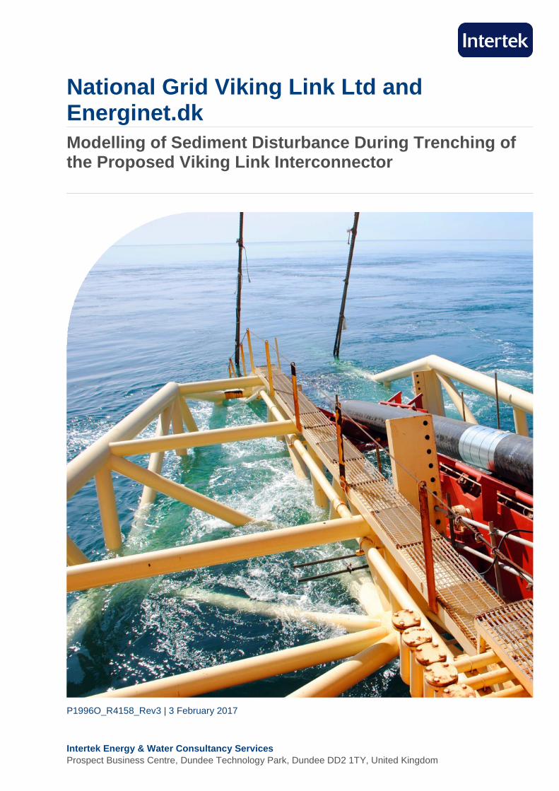
Intertek Energy & Water Consultancy Services Prospect Business Centre, Dundee Technology Park, Dundee DD2 1TY, United Kingdom
National Grid Viking Link Ltd and Energinet.dk Modelling of Sediment Disturbance During Trenching of the Proposed Viking Link Interconnector
P1996O_R4158_Rev3 | 3 February 2017
National Grid Viking Link Ltd and Energinet.dk Modelling of Sediment Disturbance During Trenching of the Proposed Viking Link Interconnector
P1996O_R4158_Rev3 | 3 February 2017 I
National Grid Viking Link Ltd and Energinet.dk P1996O_R4158_Rev3
Modelling of Sediment Disturbance During Trenching of the Proposed Viking Link Interconnector
Project Manager Authoriser
Eric Houston Chris Mooij
Rev No Date Reason Author Checker Authoriser
Rev 0 24/10/2016 Draft for review LJS KRM CPM
Rev 1 08/11/2016 First full release LJS KRM CPM
Rev 2 18/11/2016 Incorporating client comments KRM JEH CPM
Rev 3 03/02/2017 Incorporating regulator comments LJS KRM CPM
Intertek Energy & Water Consultancy Services is the trading name of Metoc Ltd, a member of the Intertek group of companies.
Document Release Form
National Grid Viking Link Ltd and Energinet.dk Modelling of Sediment Disturbance During Trenching of the Proposed Viking Link Interconnector
P1996O_R4158_Rev3 | 3 February 2017 II
Intertek is providing marine consultancy services to National Grid Viking Link Ltd (NGVL) and Energinet.dk for the proposed Viking Link Interconnector between Denmark and the United Kingdom (crossing Danish, German, Dutch and UK waters).
This sediment modelling study was requested following receipt of the correct co-ordinates of the Klaverbank Site of Community Importance (SCI) designated site boundary in the Dutch sector of the Viking Link submarine cable route, with confirmation that the proposed Viking Link route corridor now passes through the Klaverbank SCI. The results of the sediment dispersion modelling will be used to inform the environmental assessment of impacts from submarine cable installation on the designated features of the Klaverbank SCI.
This report presents the results of modelling to predict the movement of disturbed sediments during trenching of the cable route as it passes through the Klaverbank SCI.
Sediment dispersion modelling was undertaken using two modules of Intertek’s North Sea and Channel Modelling System (NSCMS):
▪ A Hydrodynamic (HD) model, which simulated water levels and current flows.
▪ A Particle Analysis (PA) model, which predicted suspended concentrations and settling depths as the sediment plume is advected and dispersed through the water column under the influence of the HD model.
A moving discharge of sediment was simulated, representing the trenching operation within the Klaverbank SCI. The sediment modelling was based on a trenching operation from west to east, although the study outputs and conclusions would be very similar were the trenching to be undertaken from east to west. The submarine cable corridor was assigned a typical width of 500 m. The location of the cable trench was assumed to be on the centreline of the submarine cable corridor. Modelling was undertaken along the entire submarine cable route within the Klaverbank SCI, plus at least 2.5 km either side of the site boundary, so that impacts from activities outside the SCI boundary would be captured.
The composition of the disturbed sediment was determined by analysing sediment sample results from the recent seabed survey (Fugro, 2016), and adopting a representative fine sediment composition based on samples collected along the submarine route corridor within the Klaverbank SCI.
Since the final trenching approach has yet to be decided, both jetting and ploughing options were modelled, each with representative trenching speeds and volume and rate of material discharged. The potential jetting discharge was assumed to be larger with a conservative 30% of the trench contents becoming suspended. The ploughing discharge was assumed to be minimal with only 1% of the trench contents being suspended. When the cross-sectional area of jetted and ploughed trenches is taken into account, it is estimated that a jetting trencher will suspend approximately seven times more sediment per unit length of cable trench than a plough.
A suspended sediment concentration (SSC) of 10 mg/l has been adopted as an indicator of potential impact, since this concentration is likely to be exceeded regularly as a result of natural processes (Stanev et al., 2008; UKMMAS, 2010). Background SSC is reported to vary widely with values well above 10 mg/l reported during stormy conditions. Based on data for similar environments to the study area, peak SSC is expected regularly to exceed 50 mg/l and may be as high as 200 mg/l.
Summary
National Grid Viking Link Ltd and Energinet.dk Modelling of Sediment Disturbance During Trenching of the Proposed Viking Link Interconnector
P1996O_R4158_Rev3 | 3 February 2017 III
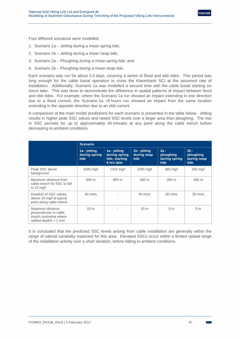
Four different scenarios were modelled:
1. Scenario 1a – Jetting during a mean spring tide;
2. Scenario 1b – Jetting during a mean neap tide;
3. Scenario 2a – Ploughing during a mean spring tide; and
4. Scenario 2b – Ploughing during a mean neap tide.
Each scenario was run for about 3.5 days, covering a series of flood and ebb tides. This period was long enough for the cable burial operation to cross the Klaverbank SCI at the assumed rate of installation. Additionally, Scenario 1a was modelled a second time with the cable burial starting six hours later. This was done to demonstrate the difference in spatial patterns of impact between flood and ebb tides. For example, where the Scenario 1a run showed an impact extending in one direction due to a flood current, the Scenario 1a +6 hours run showed an impact from the same location extending in the opposite direction due to an ebb current.
A comparison of the main model predictions for each scenario is presented in the table below. Jetting results in higher peak SSC values and raised SSC levels over a larger area than ploughing. The rise in SSC persists for up to approximately 40 minutes at any point along the cable trench before decreasing to ambient conditions.
Scenario
1a - jetting during spring tide
1a - jetting during spring tide, starting 6 hrs later
1b - jetting during neap tide
2a - ploughing during spring tide
2b - ploughing during neap tide
Peak SSC above background
1580 mg/l 1315 mg/l 1290 mg/l 360 mg/l 350 mg/l
Maximum distance from cable trench for SSC to fall to 10 mg/l
550 m 950 m 400 m 350 m 400 m
Duration of SSC values above 10 mg/l at typical point along cable trench
40 mins - 40 mins 30 mins 30 mins
Maximum distance perpendicular to cable trench centreline where settled depths > 1 mm
10 m - 10 m 5 m 5 m
It is concluded that the predicted SSC levels arising from cable installation are generally within the range of natural variability expected for this area. Elevated SSCs occur within a limited spatial range of the installation activity over a short duration, before falling to ambient conditions.
National Grid Viking Link Ltd and Energinet.dk Modelling of Sediment Disturbance During Trenching of the Proposed Viking Link Interconnector
P1996O_R4158_Rev3 | 3 February 2017 IV
Document Release Form I
Summary II
Glossary VI
1. Introduction 1
2. Study methodology 3 2.1 The North Sea and Channel Modelling System 3
2.2 The Hydrodynamic (HD) model 3
2.3 The Particle Analysis (PA) model 3
2.4 Dispersion modelling setup 4
2.5 Dispersion modelling outputs 4
3. Model inputs and assumptions 5 3.1 Seabed conditions 5
3.2 Background suspended sediment concentration 7
3.3 Submarine cable configuration 8
3.4 Key modelling parameters 8
3.5 Tidal conditions 10
3.6 Scenarios modelled 10
4. Model predictions 11 4.1 Description of presentations 11
4.2 Scenario 1a – jetting during spring tide 12
4.3 Scenario 1b – jetting during neap tide 21
4.4 Scenario 2a – ploughing during spring tide 26
4.5 Scenario 2b – ploughing during neap tide 32
5. Discussion and Conclusions 39 5.1 Summary of modelling results 39
5.2 Related research 39
References 40
Contents
National Grid Viking Link Ltd and Energinet.dk Modelling of Sediment Disturbance During Trenching of the Proposed Viking Link Interconnector
P1996O_R4158_Rev3 | 3 February 2017 V
Tables Table 3-1 Sediment PSDs along the submarine cable corridor within the Klaverbank SCI 7 Table 3-2 Sediment discharge parameters 9 Table 5-1 Summary of modelling results 39
Figures Figure 1-1 Overview of interconnector route and designated areas 2 Figure 3-1 Location of Fugro survey sediment samples 6 Figure 3-2 Predicted current speeds near the centre of the submarine cable corridor through the
Klaverbank SCI 10 Figure 4-1 Time-maximum of SSC (mg/l), Scenario 1a 13 Figure 4-2 Time-maximum of SSC (mg/l), Scenario 1a, discharging 6 hours later 14 Figure 4-3 Instantaneous SSC, jetting during spring tide 16 Figure 4-4 Variation of SSC as jetting trencher passes fixed point along cable trench 17 Figure 4-5 Instantaneous SSC, jetting during spring tide, starting 6 hours later 18 Figure 4-6 Predicted deposition depth (mm), Scenario 1a 20 Figure 4-7 Cross section of deposition depth at fixed point along cable trench, Scenario 1a 21 Figure 4-8 Time-maximum of SSC (mg/l), Scenario 1b 22 Figure 4-9 Instantaneous SSC, Scenario 1b 23 Figure 4-10 Variation of SSC as jetter passes fixed point along cable trench 24 Figure 4-11 Predicted settled depth (mm), Scenario 1b 25 Figure 4-12 Cross section of deposition depth at fixed point along cable trench, Scenario 1b 26 Figure 4-13 Time-maximum of SSC (mg/l), Scenario 2a 27 Figure 4-14 Instantaneous SSC, Scenario 2a 29 Figure 4-15 Variation of SSC as plough passes fixed point along cable trench 30 Figure 4-16 Predicted deposition depth (mm), Scenario 2a 31 Figure 4-17 Cross section of deposition depth at fixed point along cable trench, Scenario 2a 32 Figure 4-18 Time-maximum of SSC (mg/l), Scenario 2b 33 Figure 4-19 Instantaneous SSC, Scenario 2b 35 Figure 4-20 Variation of SSC as plough passes fixed point along cable trench 36 Figure 4-21 Predicted settled depth (mm), Scenario 2b 37 Figure 4-22 Cross section of deposition depth at fixed point along cable trench, Scenario 2b 38
List of Tables and Figures

National Grid Viking Link Ltd and Energinet.dk Modelling of Sediment Disturbance During Trenching of the Proposed Viking Link Interconnector
P1996O_R4158_Rev3 | 3 February 2017 VI
DoL Depth of Lowering
EEZ Exclusive Economic Zone
HD Hydrodynamic
HVDC High Voltage Direct Current
MIND Mass Impregnated Non-Draining
NGVL National Grid Viking Link Ltd
NSCMS North Sea and Channel Modelling System
PA Particle analysis
PSD Particle size distribution
pSAC Possible Special Area of Conservation
SAC Special Area of Conservation
SCI Site of Community Importance
SNS Southern North Sea
SSC Suspended sediment concentration
Glossary
National Grid Viking Link Ltd and Energinet.dk Modelling of Sediment Disturbance During Trenching of the Proposed Viking Link Interconnector
P1996O_R4158_Rev3 | 3 February 2017 1
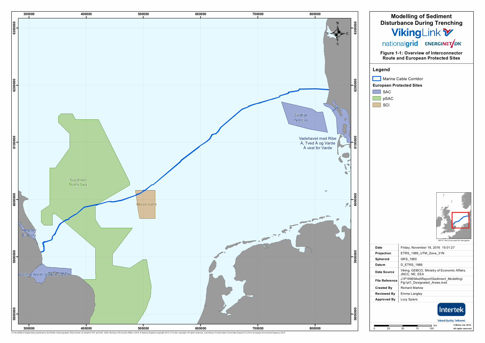
1. Introduction Intertek is providing marine consultancy services to National Grid Viking Link Ltd (NGVL) and Energinet.dk for the proposed Viking Link Interconnector between Denmark and the United Kingdom (crossing Danish, German, Dutch and UK waters – see Figure 1-1).
This sediment modelling study was requested following receipt of the correct co-ordinates of the Klaverbank Site of Community Importance (SCI) designated site boundary in the Dutch sector of the Viking Link submarine cable route, with confirmation that the proposed Viking Link route corridor now passes through the Klaverbank SCI as shown in Figure 1-1. The results of the sediment dispersion modelling will be used to inform the environmental assessment of impacts from submarine cable installation on the designated features of the Klaverbank SCI.
This report presents modelling results showing the predicted movement of disturbed sediments during trenching of the cable route as it passes through the Klaverbank SCI.
.Modelling of Sediment
Disturbance During Trenching
Figure 1-1: Overview of InterconnectorRoute and European Protected Sites
Created ByReviewed By
Richard Marlow
Friday, November 18, 2016 15:01:27ETRS_1989_UTM_Zone_31N
D_ETRS_1989Viking, GEBCO, Ministry of Economic Affairs,JNCC, NE, EEAJ:\P1996\Mxd\Report\Sediment_Modelling\Fig1pt1_Designated_Areas.mxd
GRS_1980
DateProjection
DatumData Source
File Reference
Spheroid
NOT E: Not to be used for Navigation
© T he GEBC O Digita l Atlas published by the British Oceanographic Data Centre on behalf o f IOC and IHO, 2003; M inistry o f Economic Affa irs, 2016; © Natura l England copyright 2015; © Crown copyright. A ll rights reserved. Jo in t Nature Conservation C omm ittee Support Co 2016; European Envi ronment Agency, 2016
Approved By
SydligeNordsø
Vadehavet med RibeÅ, Tved Å og Varde
Å vest for Varde
Klaverbank
SouthernNorth Sea
HumberEstuary
The Wash & North Norfolk Coast
300000
300000
400000
400000
500000
500000
600000
600000
700000
700000
800000
800000
5800
000
5800
000
5900
000
5900
000
6000
000
6000
000
6100
000
6100
000
6200
000
6200
000
6300
000
6300
000
0 25 50 75 100km
.
© Metoc Ltd, 2016.All rights reserved.
Emma LangleyLucy Spiers
LegendMarine Cable Corridor
European Protected SitesSACpSACSCI
National Grid Viking Link Ltd and Energinet.dk Modelling of Sediment Disturbance During Trenching of the Proposed Viking Link Interconnector
P1996O_R4158_Rev3 | 3 February 2017 3
2. Study methodology This Section presents an overview of the modelling tools and techniques used in the present study.
2.1 The North Sea and Channel Modelling System The dispersion model used in this study is Intertek’s North Sea and Channel Modelling System (NSCMS). This is based on an internationally recognised suite of modelling tools covering an extensive range of physical, chemical and biological processes. It is used widely, by Intertek and others, in support of marine impact assessments for regulatory requirements.
Two modules were used:
▪ A Hydrodynamic (HD) model for the North Sea, which simulated water levels and current flows.
▪ A Particle Analysis (PA) model, which predicted suspended concentrations and settling depths as the plume is advected and dispersed through the water column under the influence of the HD model.
2.2 The Hydrodynamic (HD) model The HD model simulates water levels and current flows. The NSCMS HD model was originally constructed for use in water quality modelling studies – both to undertake these studies directly, and to provide boundary conditions for local, high resolution sub-grids. A full calibration and validation exercise was undertaken prior to commissioning the modelling system (Metoc, 2008). Target model performance standards were taken from the guidelines recommended by the Foundation for Water Research (FWR, 1993), which are widely used throughout the UK and accepted by (for example) the Environment Agency and the Scottish Environment Protection Agency.
The NSCMS adopts a regular grid with a spatial resolution of 1350 m. This is considered sufficient for resolving the broader hydrodynamic features in the area surrounding the cable route, although it will be insufficient to reproduce – for example – localised flow patterns over and around sand waves.
The HD model represents tidal currents which are the dominating factor for short-term, localised dispersion of sediments. Flows are two-dimensional (depth-averaged), although the PA module allows pseudo-3D flow effects to be incorporated, such as vertical shear due to bed friction and near-surface wind drift currents.
2.3 The Particle Analysis (PA) model The PA model, contained within the NSCMS, was used to predict suspended sediment concentrations (SSC) and settling depths as the disturbed sediment is advected and dispersed by tidal currents. A large number of particles was released into the model to represent the sediment discharge during trenching. These were allowed to advect under the influence of time-varying tidal currents provided by the HD model. They were also allowed to disperse due to turbulent mixing in both the horizontal and vertical directions. Settling velocities for each particle size class were assigned based on empirically-determined rates.
PA model output is a three-dimensional time-varying prediction of SSC and settled sediment depth. The spatial resolution of the output may be set by the user and is not limited by the underlying HD model resolution. For the current study, the underlying HD model was used to provide current data that were interpolated to a 10 m x 10 m regular horizontal grid within the PA model. Predicted SSC was output for the bottom 3 m of the water column. This was
National Grid Viking Link Ltd and Energinet.dk Modelling of Sediment Disturbance During Trenching of the Proposed Viking Link Interconnector
P1996O_R4158_Rev3 | 3 February 2017 4
judged to be a suitable layer over which to assess impacts, since sediment disturbance was modelled as occurring up to a maximum initial height of 3 m above bed. Depth-averaged SSC would be significantly lower than near-bed concentrations and might have given non-conservatively low predictions of maximum concentration, so this metric was not used.
2.4 Dispersion modelling setup The setup of the HD and PA models for the study is summarised as follows.
▪ The model was run for about 3.5 days on each of a mean spring tide and mean neap tide. This run length was sufficient to capture the full trenching operation through the Klaverbank SCI (which should take about 2-3 days using either jetting or ploughing techniques at the assumed rate of installation), plus an additional period to capture any ongoing dispersion and settling of sediment once the trenching through the Klaverbank SCI was complete.
▪ The 3.5-day model run period naturally includes a number of flood and ebb tidal periods. The same 3.5-day period was used for all of the main model runs. Additional, one of the model scenarios was run a second time with the cable burial starting six hours later. This was done to demonstrate the difference in spatial patterns of impact between flood and ebb tides. For example, where the original run showed an impact extending in one direction due to a flood current, the plus-six-hour run showed an impact from the same location extending in the opposite direction due to an ebb current. The purpose of this was to give an idea of the spatial envelope of possible impacts.
▪ The HD model was run on a timestep of 60 s. This was determined during the original model calibration and validation to give a suitable balance between computational run times and model stability.
▪ The PA model was run on a timestep of 5 minutes. This reflected a suitable balance between computational run times, model output requirements, and the need to resolve the discharge accurately in space (e.g. without it looking discontinuous or patchy, as can happen if the PA timestep is too long). The selected timestep was short enough to resolve the 12.5-hour tidal cycle accurately, and to ensure that particles in the PA model moved smoothly from grid cell to grid cell under local current speeds.
▪ About 17,000 particles were released per PA model timestep. Tests found that this release rate was suitable to generate smooth time series and spatial outputs. No significant improvement in outputs would have been gained from a higher release rate.
▪ No surface wind drift current was applied since in the focus of the assessment was on the bottom part of the water column where such effects are negligible.
▪ Turbulent mixing in the horizontal and vertical directions was included in the PA model. Suitable values for the dispersion coefficients were used. These were selected based on a combination of: values derived during model construction; an Intertek literature review of values throughout the UK continental shelf; consideration of the location and depth of the study site; and Intertek experience.
2.5 Dispersion modelling outputs The PA model was used to predict time-varying three-dimensional impact concentrations.
An output timestep of 10 minutes was used. This is considered suitable to resolve time-varying concentrations in a tidally-dominated environment.
The spatial resolution of the PA model output was 10 m x 10 m in the horizontal. The vertical resolution was 3 m in a single layer above the seabed, within which the predicted SSC was calculated. The depth of sediment once settled on the seabed was also stored as a model output.
National Grid Viking Link Ltd and Energinet.dk Modelling of Sediment Disturbance During Trenching of the Proposed Viking Link Interconnector
P1996O_R4158_Rev3 | 3 February 2017 5
3. Model inputs and assumptions This Section details the key modelling inputs and setup parameters that were used during the sediment modelling study. It identifies the main data sources that have been used and the assumptions that have been made in defining the model input parameters.
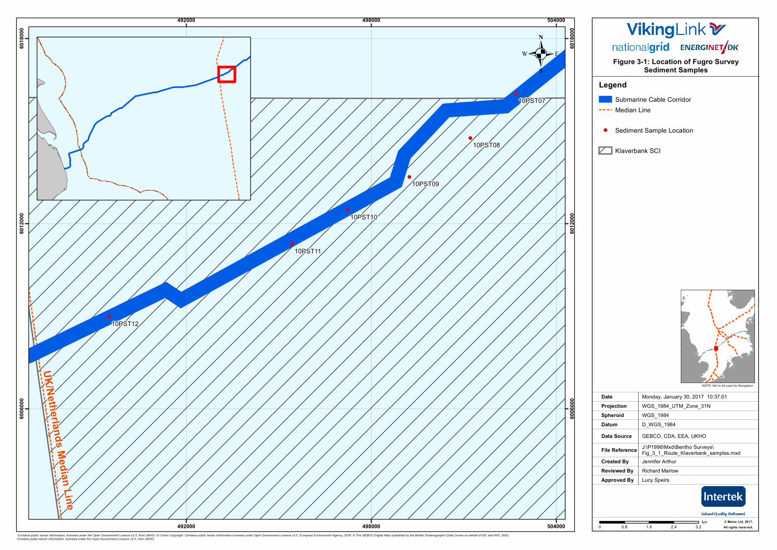
3.1 Seabed conditions The near-surface seabed sediment composition along the submarine cable corridor within the Klaverbank SCI has been defined using measured sediment samples. These were collected in May 2016 as part of an environmental (benthic) survey which formed Work Package E of the Viking Link Cable Route Survey (Fugro, 2016).
Six sediment samples were collected in (or very close to) the Klaverbank SCI, as shown in Figure 3-1. Of these, four lie along the proposed cable route corridor. Each sample was analysed using a combination of dry sieving for coarser particles (≥1000 µm) and laser diffraction for finer particles (<1000 µm). This analysis generated a Particle Size Distribution (PSD) quantifying the fraction of the total sediment mass that falls within each particle size class.
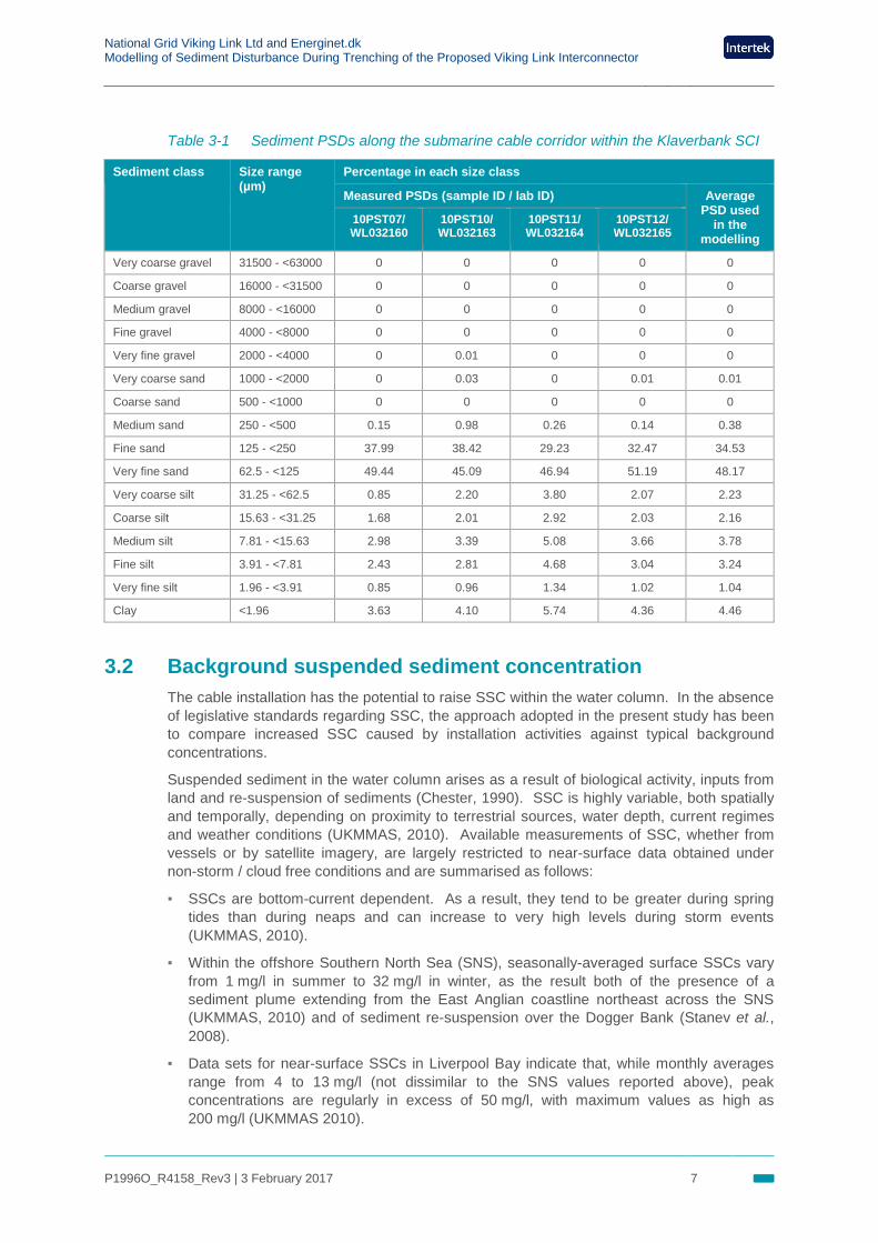
It was found that the four samples of interest displayed very similar PSDs, indicating that sediments along the submarine cable corridor within the Klaverbank SCI are of similar composition. As such, for modelling purposes the four sample PSDs were averaged in order to generate a single representative PSD. This was used for all sediment modelling in the present study. Table 3-1 presents the PSDs obtained from the four relevant samples, and the representative PSD derived by averaging these.
. Figure 3-1: Location of Fugro Survey Sediment Samples
Created ByReviewed By
Jennifer ArthurRichard Marlow
Monday, January 30, 2017 10:37:01WGS_1984_UTM_Zone_31N
D_WGS_1984GEBCO, CDA, EEA, UKHOJ:\P1996\Mxd\Bentho Surveys\Fig_3_1_Route_Klaverbank_samples.mxd
WGS_1984
DateProjection
DatumData Source
File Reference
Spheroid
NOTE: Not to be used for Navigation
Approved By Lucy Speirs
!
!
!
!
!
!
10PST12
10PST11
10PST10
10PST09
10PST08
10PST07
492000
492000
498000
498000
504000
504000
6006
000
6006
000
6012
000
6012
000
6018
000
6018
000
LegendSubmarine Cable CorridorMedian Line
! Sediment Sample Location
Klaverbank SCI
0 0.8 1.6 2.4 3.2km
.
UK/Netherlands Median Line
© Metoc Ltd, 2017.All rights reserved.
Contains public sector information, licensed under the Open Government Licence v2.0, from UKHO. © Crown Copyright. Contains public sector information licensed under Open Government Licence v3.0. European Environment Agency, 2016. © The GEBCO Digital Atlas published by the British Oceanographic Data Centre on behalf of IOC and IHO, 2003.Contains public sector information, licensed under the Open Government Licence v2.0, from UKHO
National Grid Viking Link Ltd and Energinet.dk Modelling of Sediment Disturbance During Trenching of the Proposed Viking Link Interconnector
P1996O_R4158_Rev3 | 3 February 2017 7
Table 3-1 Sediment PSDs along the submarine cable corridor within the Klaverbank SCI
Sediment class Size range (µm)
Percentage in each size class
Measured PSDs (sample ID / lab ID) Average PSD used
in the modelling
10PST07/ WL032160
10PST10/ WL032163
10PST11/ WL032164
10PST12/ WL032165
Very coarse gravel 31500 - <63000 0 0 0 0 0
Coarse gravel 16000 - <31500 0 0 0 0 0
Medium gravel 8000 - <16000 0 0 0 0 0
Fine gravel 4000 - <8000 0 0 0 0 0
Very fine gravel 2000 - <4000 0 0.01 0 0 0
Very coarse sand 1000 - <2000 0 0.03 0 0.01 0.01
Coarse sand 500 - <1000 0 0 0 0 0
Medium sand 250 - <500 0.15 0.98 0.26 0.14 0.38
Fine sand 125 - <250 37.99 38.42 29.23 32.47 34.53
Very fine sand 62.5 - <125 49.44 45.09 46.94 51.19 48.17
Very coarse silt 31.25 - <62.5 0.85 2.20 3.80 2.07 2.23
Coarse silt 15.63 - <31.25 1.68 2.01 2.92 2.03 2.16
Medium silt 7.81 - <15.63 2.98 3.39 5.08 3.66 3.78
Fine silt 3.91 - <7.81 2.43 2.81 4.68 3.04 3.24
Very fine silt 1.96 - <3.91 0.85 0.96 1.34 1.02 1.04
Clay <1.96 3.63 4.10 5.74 4.36 4.46
3.2 Background suspended sediment concentration The cable installation has the potential to raise SSC within the water column. In the absence of legislative standards regarding SSC, the approach adopted in the present study has been to compare increased SSC caused by installation activities against typical background concentrations.
Suspended sediment in the water column arises as a result of biological activity, inputs from land and re-suspension of sediments (Chester, 1990). SSC is highly variable, both spatially and temporally, depending on proximity to terrestrial sources, water depth, current regimes and weather conditions (UKMMAS, 2010). Available measurements of SSC, whether from vessels or by satellite imagery, are largely restricted to near-surface data obtained under non-storm / cloud free conditions and are summarised as follows:
▪ SSCs are bottom-current dependent. As a result, they tend to be greater during spring tides than during neaps and can increase to very high levels during storm events (UKMMAS, 2010).
▪ Within the offshore Southern North Sea (SNS), seasonally-averaged surface SSCs vary from 1 mg/l in summer to 32 mg/l in winter, as the result both of the presence of a sediment plume extending from the East Anglian coastline northeast across the SNS (UKMMAS, 2010) and of sediment re-suspension over the Dogger Bank (Stanev et al., 2008).
▪ Data sets for near-surface SSCs in Liverpool Bay indicate that, while monthly averages range from 4 to 13 mg/l (not dissimilar to the SNS values reported above), peak concentrations are regularly in excess of 50 mg/l, with maximum values as high as 200 mg/l (UKMMAS 2010).
National Grid Viking Link Ltd and Energinet.dk Modelling of Sediment Disturbance During Trenching of the Proposed Viking Link Interconnector
P1996O_R4158_Rev3 | 3 February 2017 8
▪ There are increases in SSC in near-bottom waters both in water depths greater than 200 m (McCave et al., 2001) and in coastal waters (UKMMAS, 2010), resulting from natural sediment resuspension and lateral transport. Thus, near-bottom SSCs are expected to be greater than those at the surface under natural conditions, particularly following storm events when settling sediment (particularly fines) will be transported away from the coast.
These findings indicate that there are likely to be frequent short-term increases in background SSC concentrations to 10 mg/l or above in the near-bottom waters as a result of natural events, with much higher values during storm events.
From consideration of the above evidence, it was decided that, for the present study, an SSC of 10 mg/l would be adopted as an indicator of the lower limit of potential impact, since this concentration is likely to be exceeded regularly as a result of natural processes.
The background SSC was assumed to be zero in the model runs. As such, the model predictions effectively show excess SSC above the background concentration.
3.3 Submarine cable configuration The Viking Link submarine cable configuration comprises two High Voltage Direct Current (HVDC) submarine cables and an optional fibre optic cable for control purposes. The HVDC cables will be either Extruded or Mass Impregnated Non-Draining (MIND) insulation technology. Typically, these cables are 150 mm diameter and will operate at a voltage of ±525 kV, and are installed either in a single operation or separately but in same trench.
The proposed Depth of Lowering (DoL) of the cable system, defined as the distance between the top of the cables and the undisturbed seabed surface, is 1.0 m within the Dutch EEZ.
3.4 Key modelling parameters Two trenching methods – jetting and ploughing – have been modelled.
Jetting involves the physical removal of sediment along the cable route by extracting at ground level by a suction pipe and discharging the extracted sediment at a fixed height above the seabed. For the current study, this discharge height has been assumed to be 3 m above the seabed based on typical jetting operational data.
Ploughing involves the physical displacement of sediment using a plough which is dragged along the seabed, resulting in sediment being moved to either side of the plough to form two parallel berms. A small proportion of the displaced sediment will comprise fine sandy particles which will become suspended to a height above the seabed, assumed to be a maximum of 2 m in the current study.
Once the trench is created, the cable is installed and the trench will either be left to self fill, in the case of jetting, or, in the case of ploughing, the berms on either side will be physically moved back into the trench.
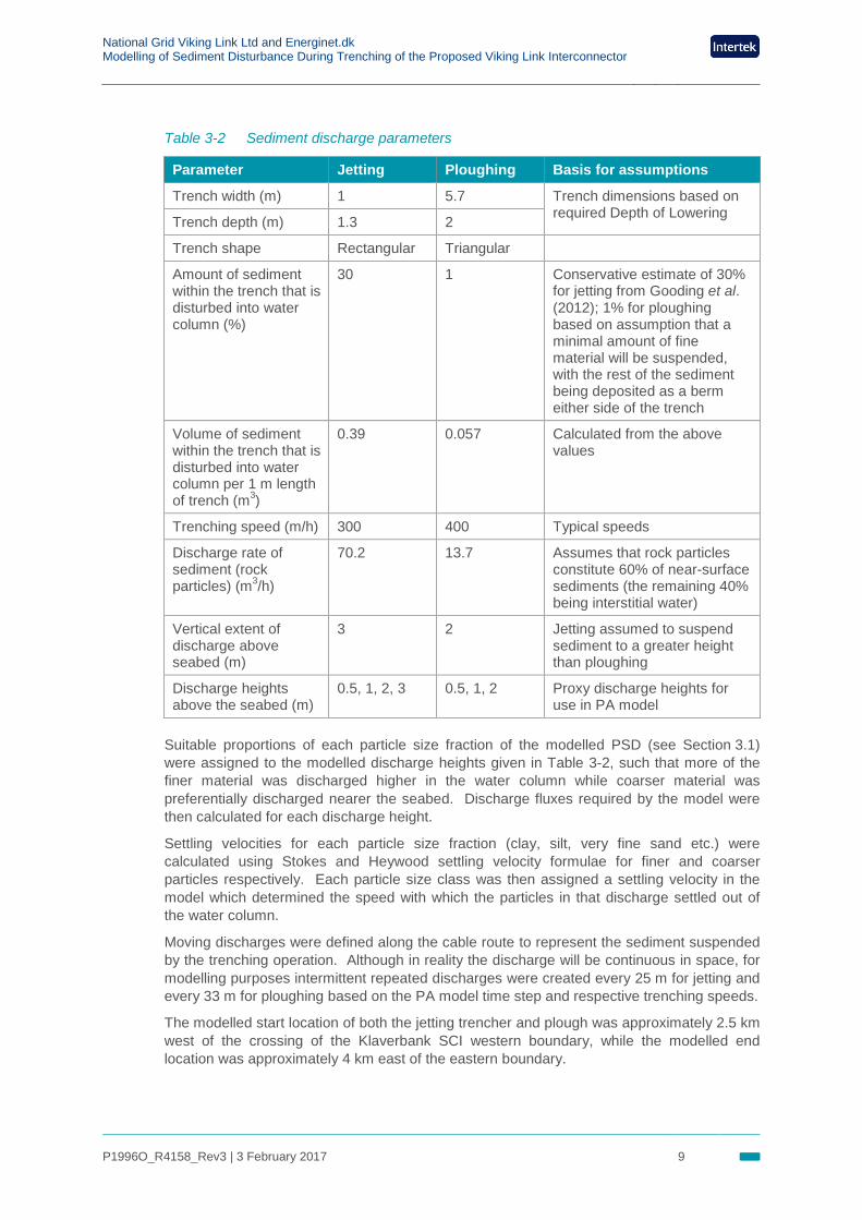
The key sediment discharge parameters for these two trenching methods are summarised in Table 3-2.
The submarine cable corridor is assumed to be 500 m wide based on standard practice. For the purposes of modelling, the cable trench is assumed to follow the centre of this cable corridor, i.e. 250 m from the corridor boundaries.
National Grid Viking Link Ltd and Energinet.dk Modelling of Sediment Disturbance During Trenching of the Proposed Viking Link Interconnector
P1996O_R4158_Rev3 | 3 February 2017 9
Table 3-2 Sediment discharge parameters
Parameter Jetting Ploughing Basis for assumptions
Trench width (m) 1 5.7 Trench dimensions based on required Depth of Lowering Trench depth (m) 1.3 2
Trench shape Rectangular Triangular
Amount of sediment within the trench that is disturbed into water column (%)
30 1 Conservative estimate of 30% for jetting from Gooding et al. (2012); 1% for ploughing based on assumption that a minimal amount of fine material will be suspended, with the rest of the sediment being deposited as a berm either side of the trench
Volume of sediment within the trench that is disturbed into water column per 1 m length of trench (m3)
0.39 0.057 Calculated from the above values
Trenching speed (m/h) 300 400 Typical speeds
Discharge rate of sediment (rock particles) (m3/h)
70.2 13.7 Assumes that rock particles constitute 60% of near-surface sediments (the remaining 40% being interstitial water)
Vertical extent of discharge above seabed (m)
3 2 Jetting assumed to suspend sediment to a greater height than ploughing
Discharge heights above the seabed (m)
0.5, 1, 2, 3 0.5, 1, 2 Proxy discharge heights for use in PA model
Suitable proportions of each particle size fraction of the modelled PSD (see Section 3.1) were assigned to the modelled discharge heights given in Table 3-2, such that more of the finer material was discharged higher in the water column while coarser material was preferentially discharged nearer the seabed. Discharge fluxes required by the model were then calculated for each discharge height.
Settling velocities for each particle size fraction (clay, silt, very fine sand etc.) were calculated using Stokes and Heywood settling velocity formulae for finer and coarser particles respectively. Each particle size class was then assigned a settling velocity in the model which determined the speed with which the particles in that discharge settled out of the water column.
Moving discharges were defined along the cable route to represent the sediment suspended by the trenching operation. Although in reality the discharge will be continuous in space, for modelling purposes intermittent repeated discharges were created every 25 m for jetting and every 33 m for ploughing based on the PA model time step and respective trenching speeds.
The modelled start location of both the jetting trencher and plough was approximately 2.5 km west of the crossing of the Klaverbank SCI western boundary, while the modelled end location was approximately 4 km east of the eastern boundary.
National Grid Viking Link Ltd and Energinet.dk Modelling of Sediment Disturbance During Trenching of the Proposed Viking Link Interconnector
P1996O_R4158_Rev3 | 3 February 2017 10
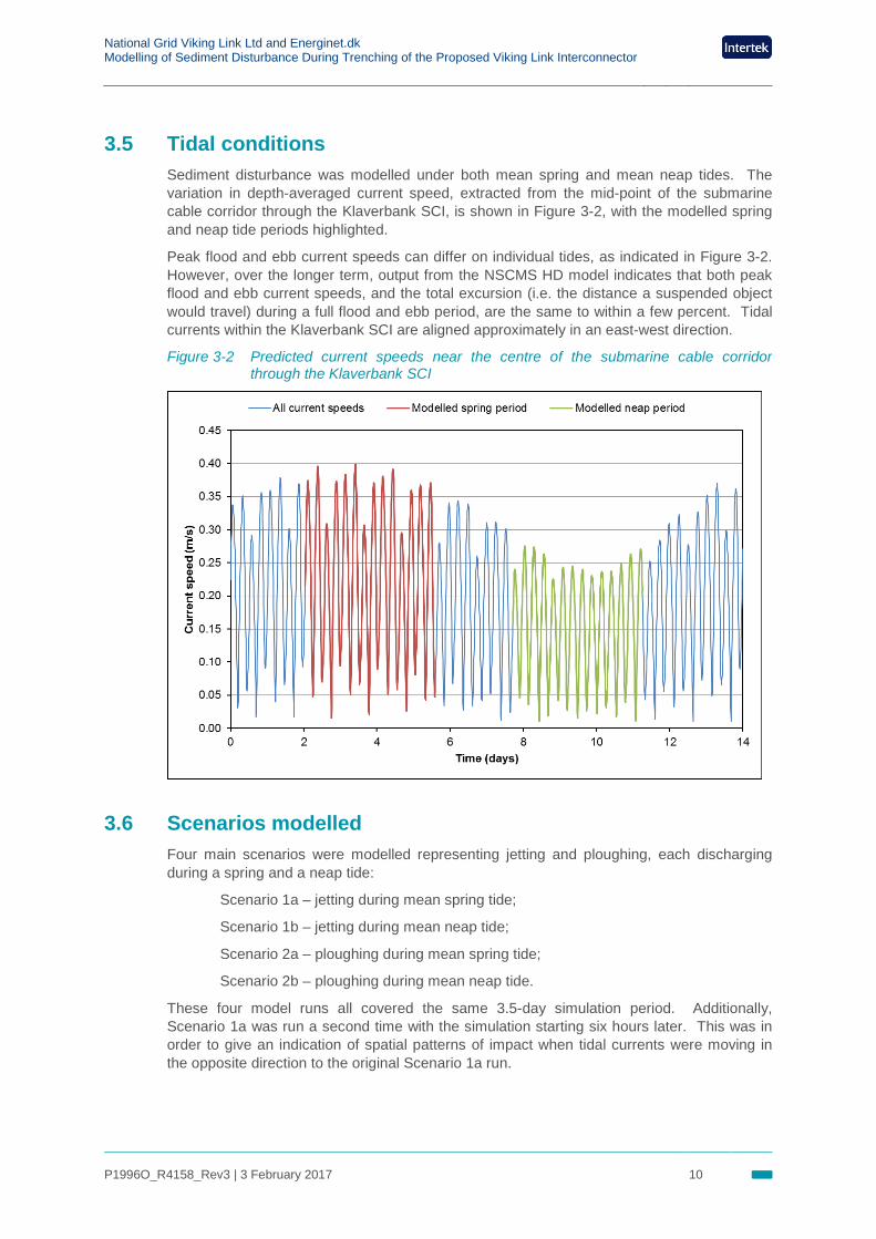
3.5 Tidal conditions Sediment disturbance was modelled under both mean spring and mean neap tides. The variation in depth-averaged current speed, extracted from the mid-point of the submarine cable corridor through the Klaverbank SCI, is shown in Figure 3-2, with the modelled spring and neap tide periods highlighted.
Peak flood and ebb current speeds can differ on individual tides, as indicated in Figure 3-2. However, over the longer term, output from the NSCMS HD model indicates that both peak flood and ebb current speeds, and the total excursion (i.e. the distance a suspended object would travel) during a full flood and ebb period, are the same to within a few percent. Tidal currents within the Klaverbank SCI are aligned approximately in an east-west direction.
Figure 3-2 Predicted current speeds near the centre of the submarine cable corridor through the Klaverbank SCI
3.6 Scenarios modelled Four main scenarios were modelled representing jetting and ploughing, each discharging during a spring and a neap tide:
Scenario 1a – jetting during mean spring tide;
Scenario 1b – jetting during mean neap tide;
Scenario 2a – ploughing during mean spring tide;
Scenario 2b – ploughing during mean neap tide.
These four model runs all covered the same 3.5-day simulation period. Additionally, Scenario 1a was run a second time with the simulation starting six hours later. This was in order to give an indication of spatial patterns of impact when tidal currents were moving in the opposite direction to the original Scenario 1a run.
National Grid Viking Link Ltd and Energinet.dk Modelling of Sediment Disturbance During Trenching of the Proposed Viking Link Interconnector
P1996O_R4158_Rev3 | 3 February 2017 11
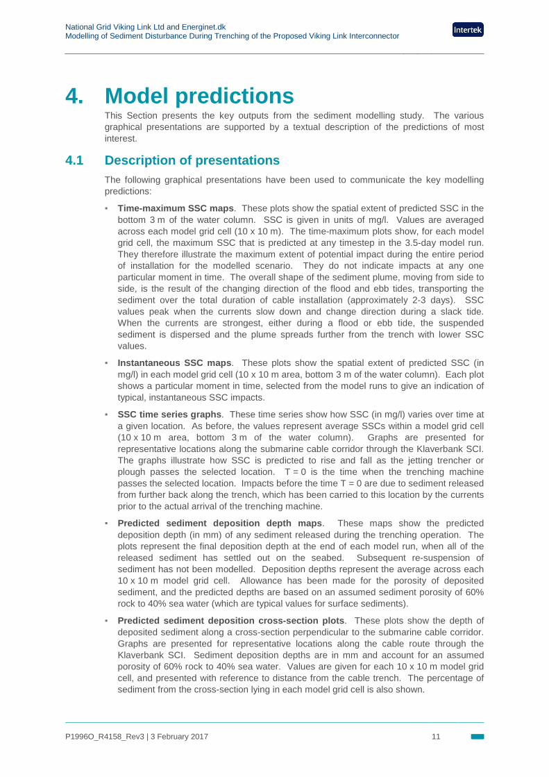
4. Model predictions This Section presents the key outputs from the sediment modelling study. The various graphical presentations are supported by a textual description of the predictions of most interest.
4.1 Description of presentations The following graphical presentations have been used to communicate the key modelling predictions:
▪ Time-maximum SSC maps. These plots show the spatial extent of predicted SSC in the bottom 3 m of the water column. SSC is given in units of mg/l. Values are averaged across each model grid cell (10 x 10 m). The time-maximum plots show, for each model grid cell, the maximum SSC that is predicted at any timestep in the 3.5-day model run. They therefore illustrate the maximum extent of potential impact during the entire period of installation for the modelled scenario. They do not indicate impacts at any one particular moment in time. The overall shape of the sediment plume, moving from side to side, is the result of the changing direction of the flood and ebb tides, transporting the sediment over the total duration of cable installation (approximately 2-3 days). SSC values peak when the currents slow down and change direction during a slack tide. When the currents are strongest, either during a flood or ebb tide, the suspended sediment is dispersed and the plume spreads further from the trench with lower SSC values.
▪ Instantaneous SSC maps. These plots show the spatial extent of predicted SSC (in mg/l) in each model grid cell (10 x 10 m area, bottom 3 m of the water column). Each plot shows a particular moment in time, selected from the model runs to give an indication of typical, instantaneous SSC impacts.
▪ SSC time series graphs. These time series show how SSC (in mg/l) varies over time at a given location. As before, the values represent average SSCs within a model grid cell (10 x 10 m area, bottom 3 m of the water column). Graphs are presented for representative locations along the submarine cable corridor through the Klaverbank SCI. The graphs illustrate how SSC is predicted to rise and fall as the jetting trencher or plough passes the selected location. T = 0 is the time when the trenching machine passes the selected location. Impacts before the time T = 0 are due to sediment released from further back along the trench, which has been carried to this location by the currents prior to the actual arrival of the trenching machine.
▪ Predicted sediment deposition depth maps. These maps show the predicted deposition depth (in mm) of any sediment released during the trenching operation. The plots represent the final deposition depth at the end of each model run, when all of the released sediment has settled out on the seabed. Subsequent re-suspension of sediment has not been modelled. Deposition depths represent the average across each 10 x 10 m model grid cell. Allowance has been made for the porosity of deposited sediment, and the predicted depths are based on an assumed sediment porosity of 60% rock to 40% sea water (which are typical values for surface sediments).
▪ Predicted sediment deposition cross-section plots. These plots show the depth of deposited sediment along a cross-section perpendicular to the submarine cable corridor. Graphs are presented for representative locations along the cable route through the Klaverbank SCI. Sediment deposition depths are in mm and account for an assumed porosity of 60% rock to 40% sea water. Values are given for each 10 x 10 m model grid cell, and presented with reference to distance from the cable trench. The percentage of sediment from the cross-section lying in each model grid cell is also shown.
National Grid Viking Link Ltd and Energinet.dk Modelling of Sediment Disturbance During Trenching of the Proposed Viking Link Interconnector
P1996O_R4158_Rev3 | 3 February 2017 12
4.2 Scenario 1a – jetting during spring tide 4.2.1 Suspended sediment concentrations, Scenario 1a
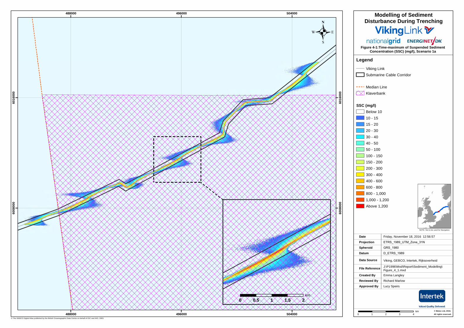
4.2.1.1 Time-maximum SSC, Scenario 1a The time-maximum SSC due to jetting is shown in Figure 4-1.
The suspended sediment gets carried furthest when the tidal current is greatest, crossing the submarine cable corridor boundary intermittently.
Along the cable trench, SSC is generally between 200-800 mg/l, reaching 1580 mg/l at certain locations during a slack tide. SSC drops rapidly a short distance from the trench, falling to below 10 mg/l within 550 m of the submarine cable route (or 300 m from the submarine cable corridor boundaries as modelled).
SSC values are at most 50 mg/l at the submarine cable corridor boundary (250 m from the cable trench as modelled), as shown in the inset in Figure 4-1. Depending on the state of the spring tide, the SSC level at the edge of the submarine cable corridor may reach 50 mg/l anywhere along the length of the cable route within the Klaverbank SCI area.
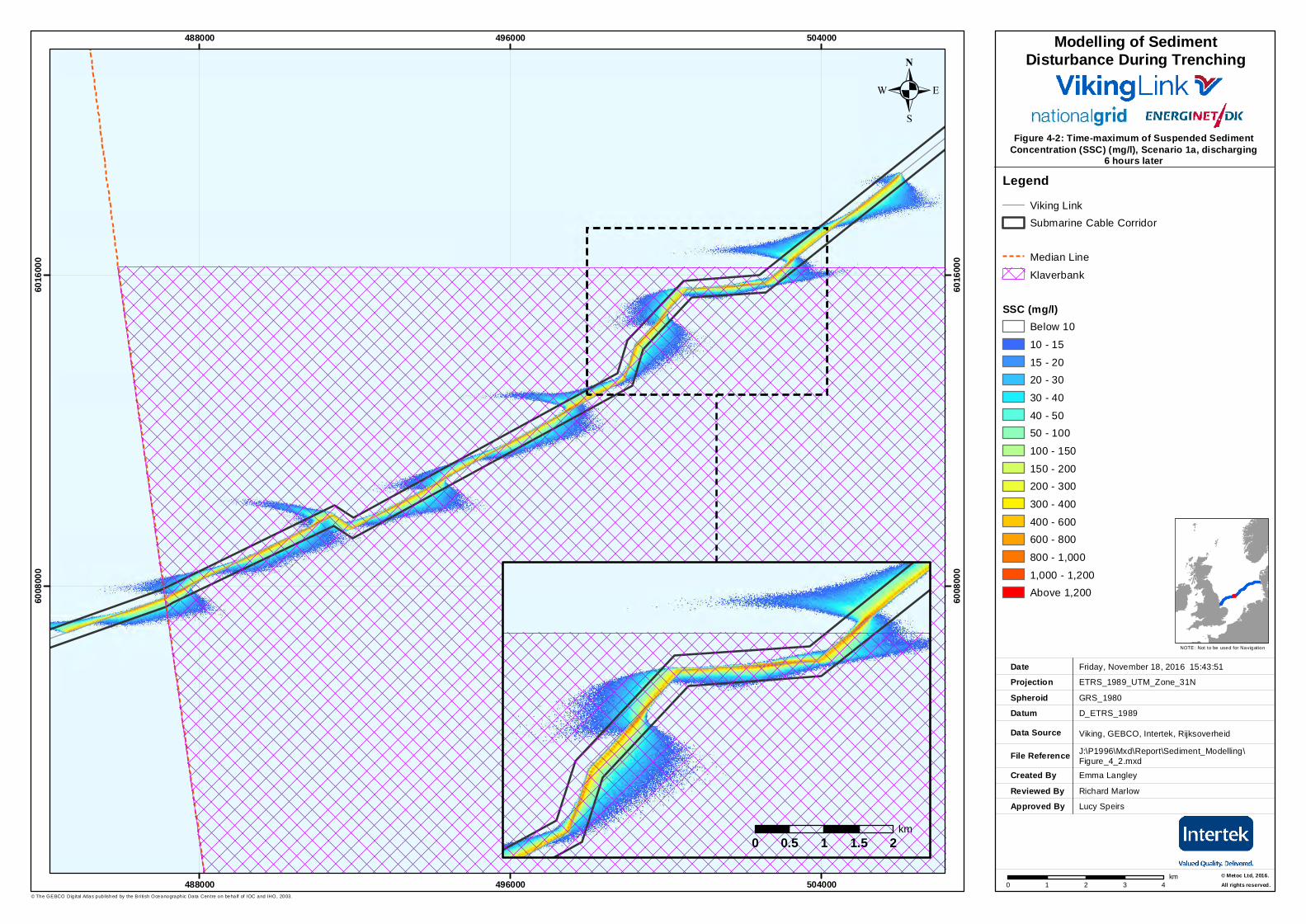
For this scenario (1a) only, a second simulation was undertaken with the jetting discharge starting six hours later to show the effects of the changing tide (see Figure 4-2). Along the cable trench SSC is generally between 400-800 mg/l, reaching a maximum of 1315 mg/l during slack tide. SSC drops rapidly a short distance from the cable trench, falling to below 10 mg/l within 1.25 km of the cable trench (or 1 km from the submarine cable corridor boundaries as modelled).
The inset within Figure 4-2 presents the modelled suspended sediment in the vicinity of the area of harder seabed substrate, when the predominant tidal flow is towards the area of harder substrate. It can be seen that the SSC level is typically 80 mg/l at the southern edge of the submarine cable corridor (250 m from the cable trench as modelled), falling to below 50 mg/l within 30 m of the cable corridor. Within 950 m of the cable trench (700 m from the submarine cable corridor as modelled), the SSC level has fallen to below 10 mg/l.
.Figure 4-1:Time-maximum of Suspended Sediment
Concentration (SSC) (mg/l), Scenario 1a
Created ByReviewed By
Emma Langley
Friday, November 18, 2016 12:56:57
ETRS_1989_UTM_Zone_31N
D_ETRS_1989
Viking, GEBCO, Intertek, Rijksoverheid
J:\P1996\Mxd\Report\Sediment_Modelling\Figure_4_1.mxd
GRS_1980
DateProjection
DatumData Source
File Reference
Spheroid
NOTE: Not to be used for Navigation
© The GEBCO Digital Atlas published by the British Oceanographic Data Centre on behalf of IOC and IHO, 2003.
Approved By
488000
488000
496000
496000
504000
504000
6008
000
6008
000
6016
000
6016
000
0 1 2 3 4km
.
© Metoc Ltd, 2016.All rights reserved.
Richard Marlow
Lucy Speirs
LegendViking LinkSubmarine Cable Corridor
Median LineKlaverbank
SSC (mg/l)Below 1010 - 1515 - 2020 - 3030 - 4040 - 5050 - 100100 - 150150 - 200200 - 300300 - 400400 - 600600 - 800800 - 1,0001,000 - 1,200Above 1,200
Modelling of SedimentDisturbance During Trenching
0 0.5 1 1.5 2km
.Figure 4-2: Time-maximum of Suspended Sediment
Concentration (SSC) (mg/l), Scenario 1a, discharging6 hours later
Created ByReviewed By
Emma Langley
Friday, November 18, 2016 15:43:51
ETRS_1989_UTM_Zone_31N
D_ETRS_1989
Viking, GEBCO, Intertek, Rijksoverheid
J:\P1996\Mxd\Report\Sediment_Modelling\Figure_4_2.mxd
GRS_1980
DateProjection
DatumData Source
File Reference
Spheroid
NOTE: Not to be used for Navigation
© The GEBCO Dig ital Atlas published by the Bri tish Oceanographic Data Centre on behalf of IOC and IHO, 2003.
Approved By
488000
488000
496000
496000
504000
504000
6008
000
6008
000
6016
000
6016
000
0 1 2 3 4km
.
© Metoc Ltd, 2016.All rights reserved.
Richard Marlow
Lucy Speirs
LegendViking LinkSubmarine Cable Corridor
Median Line
Klaverbank
SSC (mg/l)Below 10
10 - 15
15 - 2020 - 30
30 - 40
40 - 5050 - 100
100 - 150
150 - 200200 - 300
300 - 400
400 - 600600 - 800
800 - 1,000
1,000 - 1,200Above 1,200
Modelling of SedimentDisturbance During Trenching
0 0.5 1 1.5 2km
National Grid Viking Link Ltd and Energinet.dk Modelling of Sediment Disturbance During Trenching of the Proposed Viking Link Interconnector
P1996O_R4158_Rev3 | 3 February 2017 15
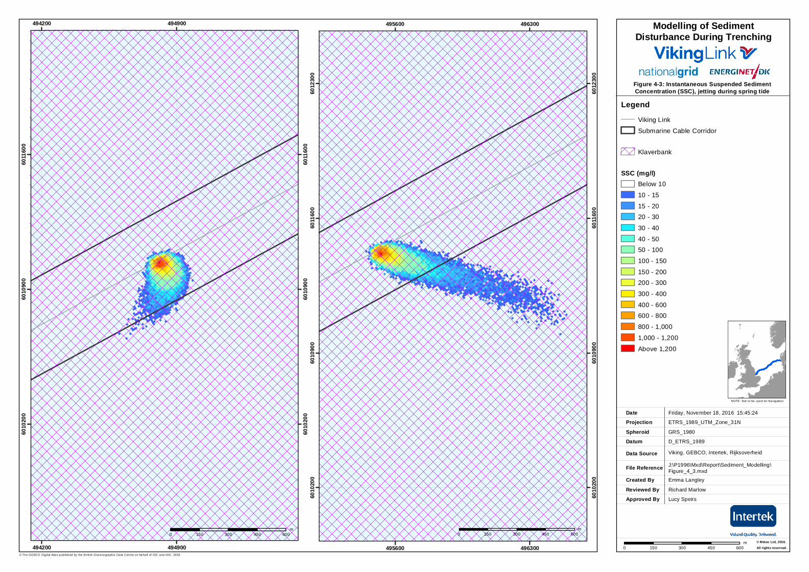
4.2.1.2 Instantaneous SSC, Scenario 1a Figure 4-3 presents close-up images of the sediment discharge at two different points in the tidal cycle. The image on the left presents the SSC distribution during a representative slack tide, whereby the SSC peaks at 1257 mg/l at the discharge location, falling to 15-20 mg/l when the plume crosses the southern boundary of the submarine cable corridor (250 m from the cable trench as modelled).
The image on the right presents the plume for sediment discharged two hours later, when the tidal currents are higher, carrying the plume to the east. In this case, the plume extends beyond the boundary of the submarine cable corridor, with peak SSC levels of 1213 mg/l at the discharge location and 45 mg/l at the edge of the submarine cable corridor. The SSC falls to <10 mg/l approximately 750 m from the cable trench (500 m from the edge of the submarine cable corridor as modelled).
.Figure 4-3: Instantaneous Suspended SedimentConcentration (SSC), jetting during spring tide
Created ByReviewed By
Emma Langley
Friday, November 18, 2016 15:45:24
ETRS_1989_UTM_Zone_31N
D_ETRS_1989
Viking, GEBCO, Intertek, Rijksoverheid
J:\P1996\Mxd\Report\Sediment_Modelling\Figure_4_3.mxd
GRS_1980
DateProjection
DatumData Source
File Reference
Spheroid
NOTE: Not to be used for Navigation
© The GEBCO Dig ital Atlas published by the Bri tish Oceanographic Data Centre on behalf of IOC and IHO, 2003.
Approved By
494200
494200
494900
494900
6010
200
6010
200
6010
900
6010
900
6011
600
6011
600
0 150 300 450 600m
.
© Metoc Ltd, 2016.All rights reserved.
Richard Marlow
Lucy Speirs
LegendViking Link
Submarine Cable Corridor
Klaverbank
SSC (mg/l)Below 10
10 - 15
15 - 2020 - 30
30 - 40
40 - 5050 - 100
100 - 150
150 - 200200 - 300
300 - 400
400 - 600600 - 800
800 - 1,000
1,000 - 1,200
Above 1,200
Modelling of SedimentDisturbance During Trenching
495600
495600
496300
496300
6010
200
6010
200
6010
900
6010
900
6011
600
6011
600
6012
300
6012
300
0 150 300 450 600m
0 150 300 450 600m
National Grid Viking Link Ltd and Energinet.dk Modelling of Sediment Disturbance During Trenching of the Proposed Viking Link Interconnector
P1996O_R4158_Rev3 | 3 February 2017 17
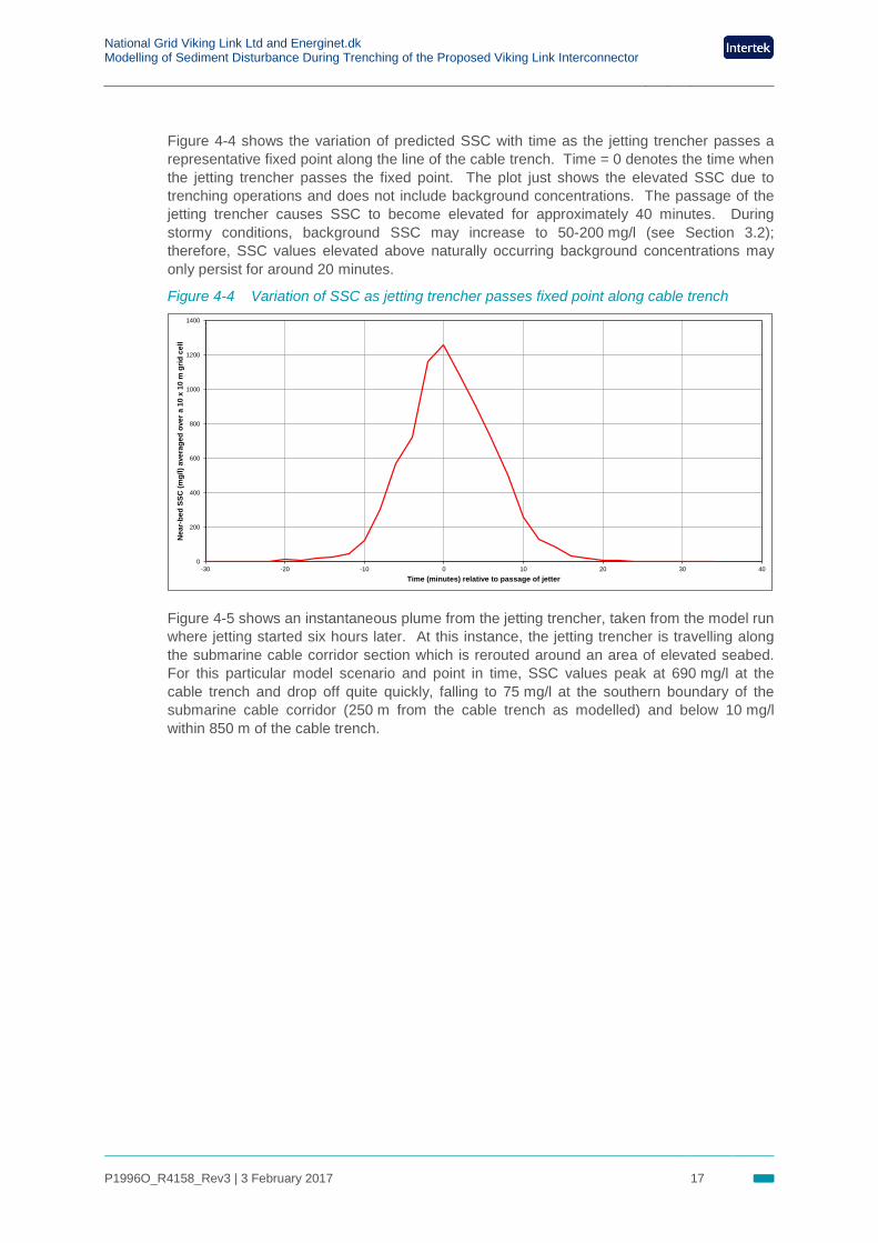
Figure 4-4 shows the variation of predicted SSC with time as the jetting trencher passes a representative fixed point along the line of the cable trench. Time = 0 denotes the time when the jetting trencher passes the fixed point. The plot just shows the elevated SSC due to trenching operations and does not include background concentrations. The passage of the jetting trencher causes SSC to become elevated for approximately 40 minutes. During stormy conditions, background SSC may increase to 50-200 mg/l (see Section 3.2); therefore, SSC values elevated above naturally occurring background concentrations may only persist for around 20 minutes.
Figure 4-4 Variation of SSC as jetting trencher passes fixed point along cable trench
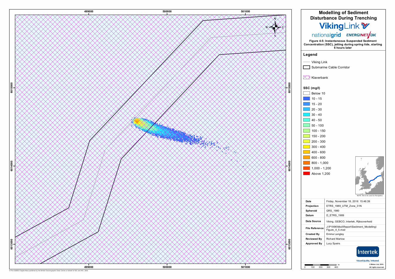
Figure 4-5 shows an instantaneous plume from the jetting trencher, taken from the model run where jetting started six hours later. At this instance, the jetting trencher is travelling along the submarine cable corridor section which is rerouted around an area of elevated seabed. For this particular model scenario and point in time, SSC values peak at 690 mg/l at the cable trench and drop off quite quickly, falling to 75 mg/l at the southern boundary of the submarine cable corridor (250 m from the cable trench as modelled) and below 10 mg/l within 850 m of the cable trench.
0
200
400
600
800
1000
1200
1400
-30 -20 -10 0 10 20 30 40
Nea
r-be
d SS
C (m
g/l)
aver
aged
ove
r a 1
0 x
10 m
grid
cel
l
Time (minutes) relative to passage of jetter
.Figure 4-5: Instantaneous Suspended Sediment
Concentration (SSC), jetting during spring tide, starting6 hours later
Created ByReviewed By
Emma Langley
Friday, November 18, 2016 15:46:39ETRS_1989_UTM_Zone_31N
D_ETRS_1989
Viking, GEBCO, Intertek, RijksoverheidJ:\P1996\Mxd\Report\Sediment_Modelling\Figure_4_5.mxd
GRS_1980
DateProjection
DatumData Source
File Reference
Spheroid
NOTE: Not to be used for Navigation
© The GEBCO Dig ital Atlas published by the Bri tish Oceanographic Data Centre on behalf of IOC and IHO, 2003.
Approved By
499000
499000
500000
500000
501000
501000
6013
000
6013
000
6014
000
6014
000
6015
000
6015
000
0 100 200 300 400m
.
© Metoc Ltd, 2016.All rights reserved.
Richard MarlowLucy Speirs
LegendViking LinkSubmarine Cable Corridor
Klaverbank
SSC (mg/l)Below 1010 - 1515 - 2020 - 3030 - 4040 - 5050 - 100100 - 150150 - 200200 - 300300 - 400400 - 600600 - 800800 - 1,0001,000 - 1,200Above 1,200
Modelling of SedimentDisturbance During Trenching
National Grid Viking Link Ltd and Energinet.dk Modelling of Sediment Disturbance During Trenching of the Proposed Viking Link Interconnector
P1996O_R4158_Rev3 | 3 February 2017 19
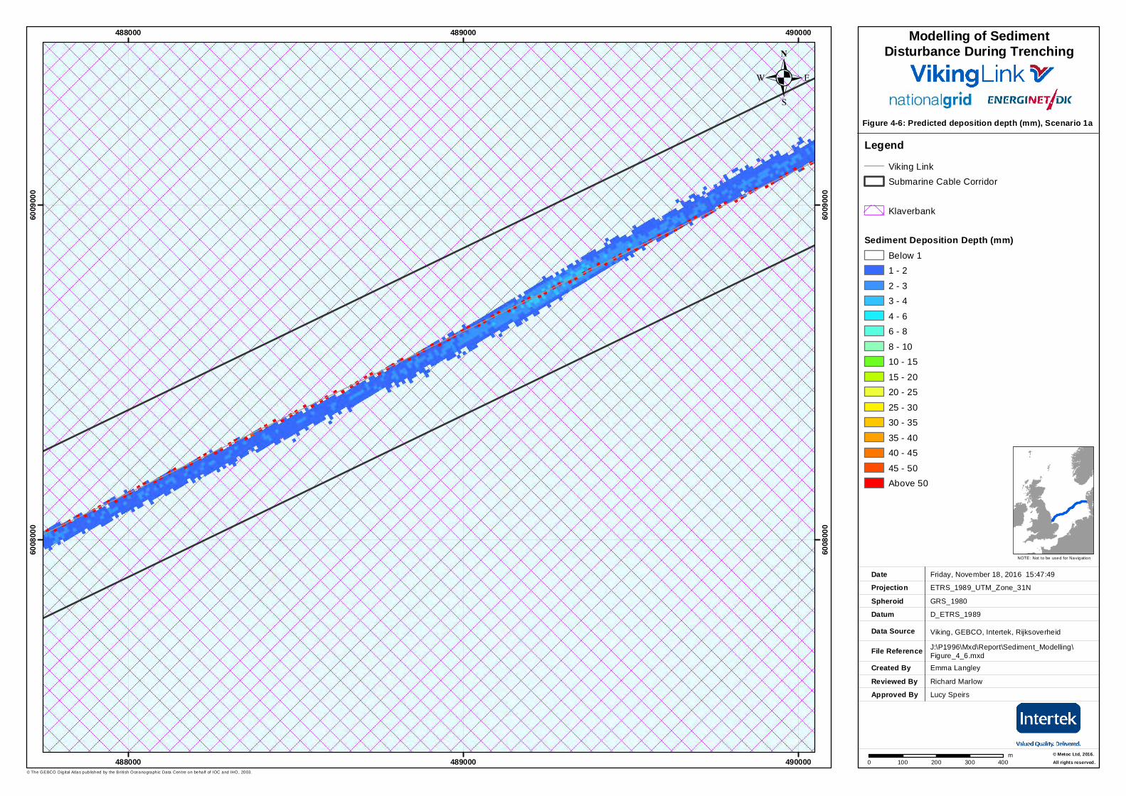
4.2.2 Sediment deposition depths, Scenario 1a The model predicts sediment deposition depths up to 55 mm along the line of the cable trench, dropping rapidly to 1 mm within about 60 m of the trench (Figure 4-6).
Note that the red cells in Figure 4-6 showing peak deposition depths of 55 m are discontinuous because the model was set up to discharge every 25 m along the line of the cable trench. In reality, a continuous red line would be shown right along the trench showing a continuous line of deposition, although the maximum deposition depth would likely be less than the predicted 55 mm because the sediment will be spread out across more model grid cells.
.Figure 4-6: Predicted deposition depth (mm), Scenario 1a
Created ByReviewed By
Emma Langley
Friday, November 18, 2016 15:47:49
ETRS_1989_UTM_Zone_31N
D_ETRS_1989
Viking, GEBCO, Intertek, Rijksoverheid
J:\P1996\Mxd\Report\Sediment_Modelling\Figure_4_6.mxd
GRS_1980
DateProjection
DatumData Source
File Reference
Spheroid
NOTE: Not to be used for Navigation
© The GEBCO Dig ital Atlas published by the Bri tish Oceanographic Data Centre on behalf of IOC and IHO, 2003.
Approved By
488000
488000
489000
489000
490000
490000
6008
000
6008
000
6009
000
6009
000
0 100 200 300 400m
.
© Metoc Ltd, 2016.All rights reserved.
Richard Marlow
Lucy Speirs
LegendViking LinkSubmarine Cable Corridor
Klaverbank
Sediment Deposition Depth (mm)Below 11 - 2
2 - 33 - 4
4 - 66 - 8
8 - 1010 - 15
15 - 2020 - 25
25 - 3030 - 35
35 - 4040 - 45
45 - 50Above 50
Modelling of SedimentDisturbance During Trenching
National Grid Viking Link Ltd and Energinet.dk Modelling of Sediment Disturbance During Trenching of the Proposed Viking Link Interconnector
P1996O_R4158_Rev3 | 3 February 2017 21
A cross section of settled depths at a representative fixed point along the cable trench is presented in Figure 4-7, showing that most of the suspended sediment settles out within 5 m of the trench centreline, reaching a maximum depth of 55 mm. Settled depth rapidly decreases to below 10 mm beyond 5 m of the trench on either side. There is very little difference in deposition depths north and south of the trench.
Figure 4-7 Cross section of deposition depth at fixed point along cable trench, Scenario 1a
4.3 Scenario 1b – jetting during neap tide 4.3.1 Suspended sediment concentrations, Scenario 1b
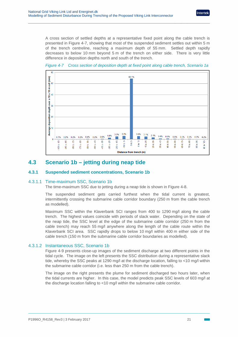
4.3.1.1 Time-maximum SSC, Scenario 1b The time-maximum SSC due to jetting during a neap tide is shown in Figure 4-8.
The suspended sediment gets carried furthest when the tidal current is greatest, intermittently crossing the submarine cable corridor boundary (250 m from the cable trench as modelled).
Maximum SSC within the Klaverbank SCI ranges from 400 to 1290 mg/l along the cable trench. The highest values coincide with periods of slack water. Depending on the state of the neap tide, the SSC level at the edge of the submarine cable corridor (250 m from the cable trench) may reach 55 mg/l anywhere along the length of the cable route within the Klaverbank SCI area. SSC rapidly drops to below 10 mg/l within 400 m either side of the cable trench (150 m from the submarine cable corridor boundaries as modelled).
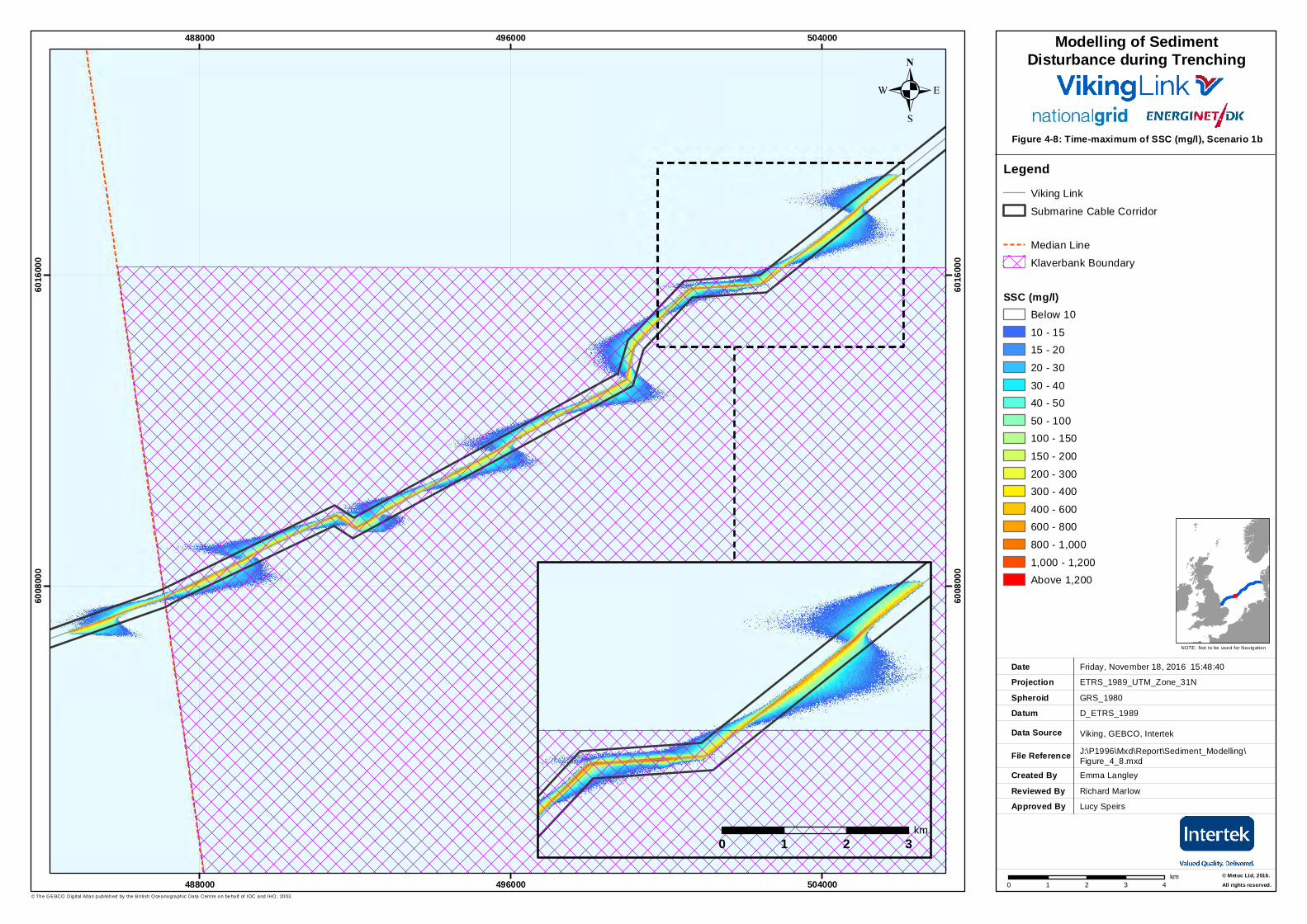
4.3.1.2 Instantaneous SSC, Scenario 1b Figure 4-9 presents close-up images of the sediment discharge at two different points in the tidal cycle. The image on the left presents the SSC distribution during a representative slack tide, whereby the SSC peaks at 1290 mg/l at the discharge location, falling to <10 mg/l within the submarine cable corridor (i.e. less than 250 m from the cable trench).
The image on the right presents the plume for sediment discharged two hours later, when the tidal currents are higher. In this case, the model predicts peak SSC levels of 603 mg/l at the discharge location falling to <10 mg/l within the submarine cable corridor.
.Figure 4-8: Time-maximum of SSC (mg/l), Scenario 1b
Created ByReviewed By
Emma Langley
Friday, November 18, 2016 15:48:40
ETRS_1989_UTM_Zone_31N
D_ETRS_1989
Viking, GEBCO, Intertek
J:\P1996\Mxd\Report\Sediment_Modelling\Figure_4_8.mxd
GRS_1980
DateProjection
DatumData Source
File Reference
Spheroid
NOTE: Not to be used for Navigation
© The GEBCO Dig ital Atlas published by the Bri tish Oceanographic Data Centre on behalf of IOC and IHO, 2003.
Approved By
488000
488000
496000
496000
504000
504000
6008
000
6008
000
6016
000
6016
000
0 1 2 3 4km
.
© Metoc Ltd, 2016.All rights reserved.
Richard Marlow
Lucy Speirs
LegendViking Link
Submarine Cable Corridor
Median Line
Klaverbank Boundary
SSC (mg/l)Below 10
10 - 1515 - 20
20 - 30
30 - 4040 - 50
50 - 100100 - 150
150 - 200
200 - 300300 - 400
400 - 600600 - 800
800 - 1,000
1,000 - 1,200Above 1,200
Modelling of SedimentDisturbance during Trenching
0 1 2 3km
.Figure 4-9: Instantaneous Suspended Sediment
Concentration (SSC) Scenario 1b
Created ByReviewed By
Emma Langley
Friday, November 18, 2016 15:50:24ETRS_1989_UTM_Zone_31N
D_ETRS_1989
Viking, GEBCO, Intertek, RijksoverheidJ:\P1996\Mxd\Report\Sediment_Modelling\Figure_4_9.mxd
GRS_1980
DateProjection
DatumData Source
File Reference
Spheroid
NOTE: Not to be used for Navigation
© The GEBCO Dig ital Atlas published by the Bri tish Oceanographic Data Centre on behalf of IOC and IHO, 2003.
Approved By
501000
501000
502000
502000
503000
503000
6014
000
6014
000
6015
000
6015
000
6016
000
6016
000
6017
000
6017
000
6018
000
6018
000
0 150 300 450 600m
.
© Metoc Ltd, 2016.All rights reserved.
Richard MarlowLucy Speirs
LegendViking LinkSubmarine Cable Corridor
Klaverbank
SSC (mg/l)Below 1010 - 1515 - 2020 - 3030 - 4040 - 5050 - 100100 - 150150 - 200200 - 300300 - 400400 - 600600 - 800800 - 1,0001,000 - 1,200Above 1,200
Modelling of SedimentDisturbance During Trenching
501000
501000
502000
502000
503000
5030006013
000
6013
000
6014
000
6014
000
6015
000
6015
000
6016
000
6016
000
6017
000
6017
000
6018
000
6018
000
0 150 300 450 600m0 150 300 450 600
m
National Grid Viking Link Ltd and Energinet.dk Modelling of Sediment Disturbance During Trenching of the Proposed Viking Link Interconnector
P1996O_R4158_Rev3 | 3 February 2017 24
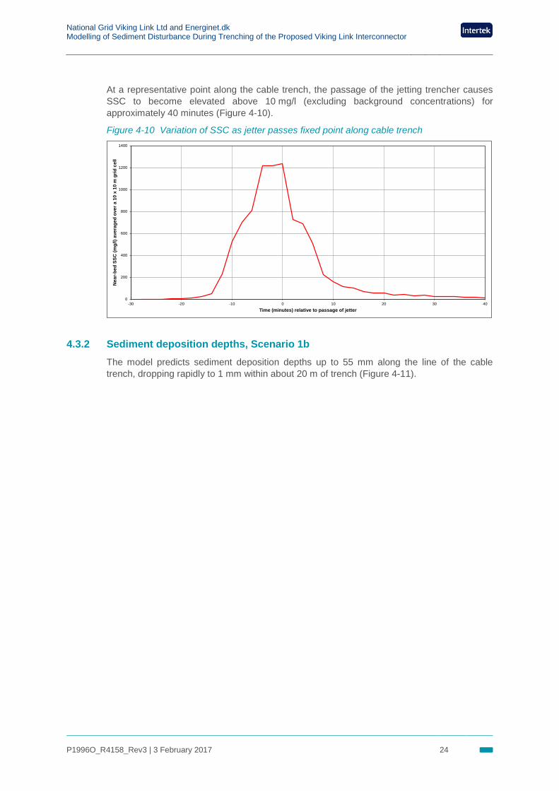
At a representative point along the cable trench, the passage of the jetting trencher causes SSC to become elevated above 10 mg/l (excluding background concentrations) for approximately 40 minutes (Figure 4-10).
Figure 4-10 Variation of SSC as jetter passes fixed point along cable trench
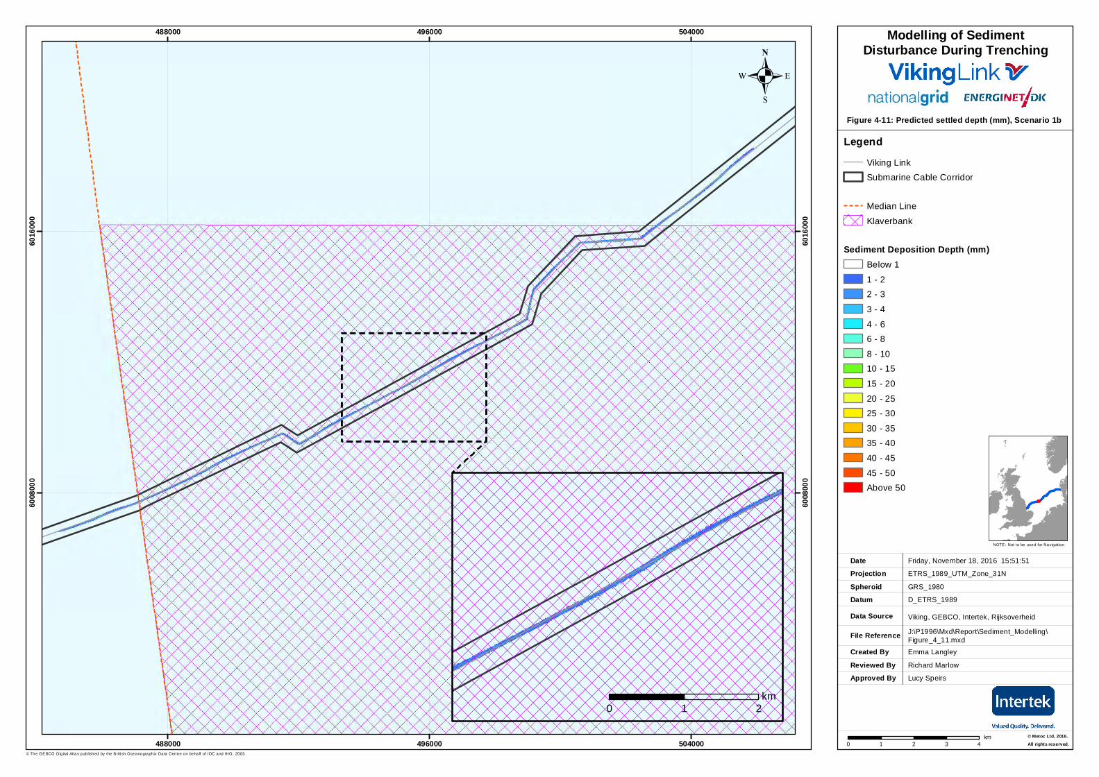
4.3.2 Sediment deposition depths, Scenario 1b The model predicts sediment deposition depths up to 55 mm along the line of the cable trench, dropping rapidly to 1 mm within about 20 m of trench (Figure 4-11).
0
200
400
600
800
1000
1200
1400
-30 -20 -10 0 10 20 30 40
Nea
r-be
d SS
C (m
g/l)
aver
aged
ove
r a 1
0 x
10 m
grid
cel
l
Time (minutes) relative to passage of jetter
.Figure 4-11: Predicted settled depth (mm), Scenario 1b
Created ByReviewed By
Emma Langley
Friday, November 18, 2016 15:51:51
ETRS_1989_UTM_Zone_31N
D_ETRS_1989
Viking, GEBCO, Intertek, Rijksoverheid
J:\P1996\Mxd\Report\Sediment_Modelling\Figure_4_11.mxd
GRS_1980
DateProjection
DatumData Source
File Reference
Spheroid
NOTE: Not to be used for Navigation
© The GEBCO Dig ital Atlas published by the Bri tish Oceanographic Data Centre on behalf of IOC and IHO, 2003.
Approved By
488000
488000
496000
496000
504000
504000
6008
000
6008
000
6016
000
6016
000
0 1 2 3 4km
.
© Metoc Ltd, 2016.All rights reserved.
Richard Marlow
Lucy Speirs
LegendViking LinkSubmarine Cable Corridor
Median Line
Klaverbank
Sediment Deposition Depth (mm)Below 1
1 - 22 - 3
3 - 4
4 - 66 - 8
8 - 1010 - 15
15 - 20
20 - 2525 - 30
30 - 3535 - 40
40 - 45
45 - 50Above 50
Modelling of SedimentDisturbance During Trenching
0 1 2km
National Grid Viking Link Ltd and Energinet.dk Modelling of Sediment Disturbance During Trenching of the Proposed Viking Link Interconnector
P1996O_R4158_Rev3 | 3 February 2017 26
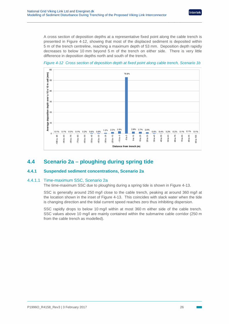
A cross section of deposition depths at a representative fixed point along the cable trench is presented in Figure 4-12, showing that most of the displaced sediment is deposited within 5 m of the trench centreline, reaching a maximum depth of 53 mm. Deposition depth rapidly decreases to below 10 mm beyond 5 m of the trench on either side. There is very little difference in deposition depths north and south of the trench.
Figure 4-12 Cross section of deposition depth at fixed point along cable trench, Scenario 1b
4.4 Scenario 2a – ploughing during spring tide 4.4.1 Suspended sediment concentrations, Scenario 2a
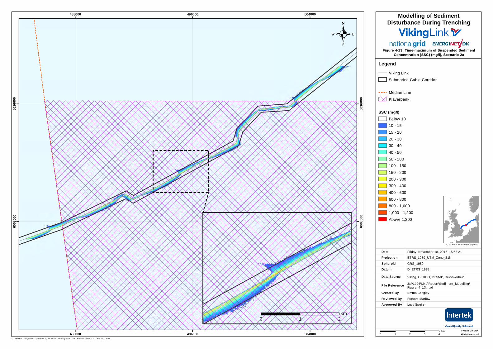
4.4.1.1 Time-maximum SSC, Scenario 2a The time-maximum SSC due to ploughing during a spring tide is shown in Figure 4-13.
SSC is generally around 250 mg/l close to the cable trench, peaking at around 360 mg/l at the location shown in the inset of Figure 4-13. This coincides with slack water when the tide is changing direction and the tidal current speed reaches zero thus inhibiting dispersion.
SSC rapidly drops to below 10 mg/l within at most 360 m either side of the cable trench. SSC values above 10 mg/l are mainly contained within the submarine cable corridor (250 m from the cable trench as modelled).
.Figure 4-13 :Time-maximum of Suspended Sediment
Concentration (SSC) (mg/l), Scenario 2a
Created ByReviewed By
Emma Langley
Friday, November 18, 2016 15:53:21
ETRS_1989_UTM_Zone_31N
D_ETRS_1989
Viking, GEBCO, Intertek, Rijksoverheid
J:\P1996\Mxd\Report\Sediment_Modelling\Figure_4_13.mxd
GRS_1980
DateProjection
DatumData Source
File Reference
Spheroid
NOTE: Not to be used for Navigation
© The GEBCO Dig ital Atlas published by the Bri tish Oceanographic Data Centre on behalf of IOC and IHO, 2003.
Approved By
488000
488000
496000
496000
504000
504000
6008
000
6008
000
6016
000
6016
000
0 1 2 3 4km
.
© Metoc Ltd, 2016.All rights reserved.
Richard Marlow
Lucy Speirs
LegendViking Link
Submarine Cable Corridor
Median Line
Klaverbank
SSC (mg/l)Below 1010 - 15
15 - 20
20 - 3030 - 40
40 - 50
50 - 100100 - 150
150 - 200
200 - 300300 - 400
400 - 600
600 - 800800 - 1,000
1,000 - 1,200
Above 1,200
Modelling of SedimentDisturbance During Trenching
0 1 2km
National Grid Viking Link Ltd and Energinet.dk Modelling of Sediment Disturbance During Trenching of the Proposed Viking Link Interconnector
P1996O_R4158_Rev3 | 3 February 2017 28
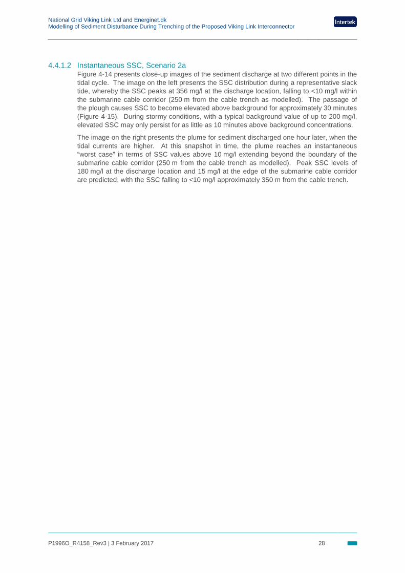
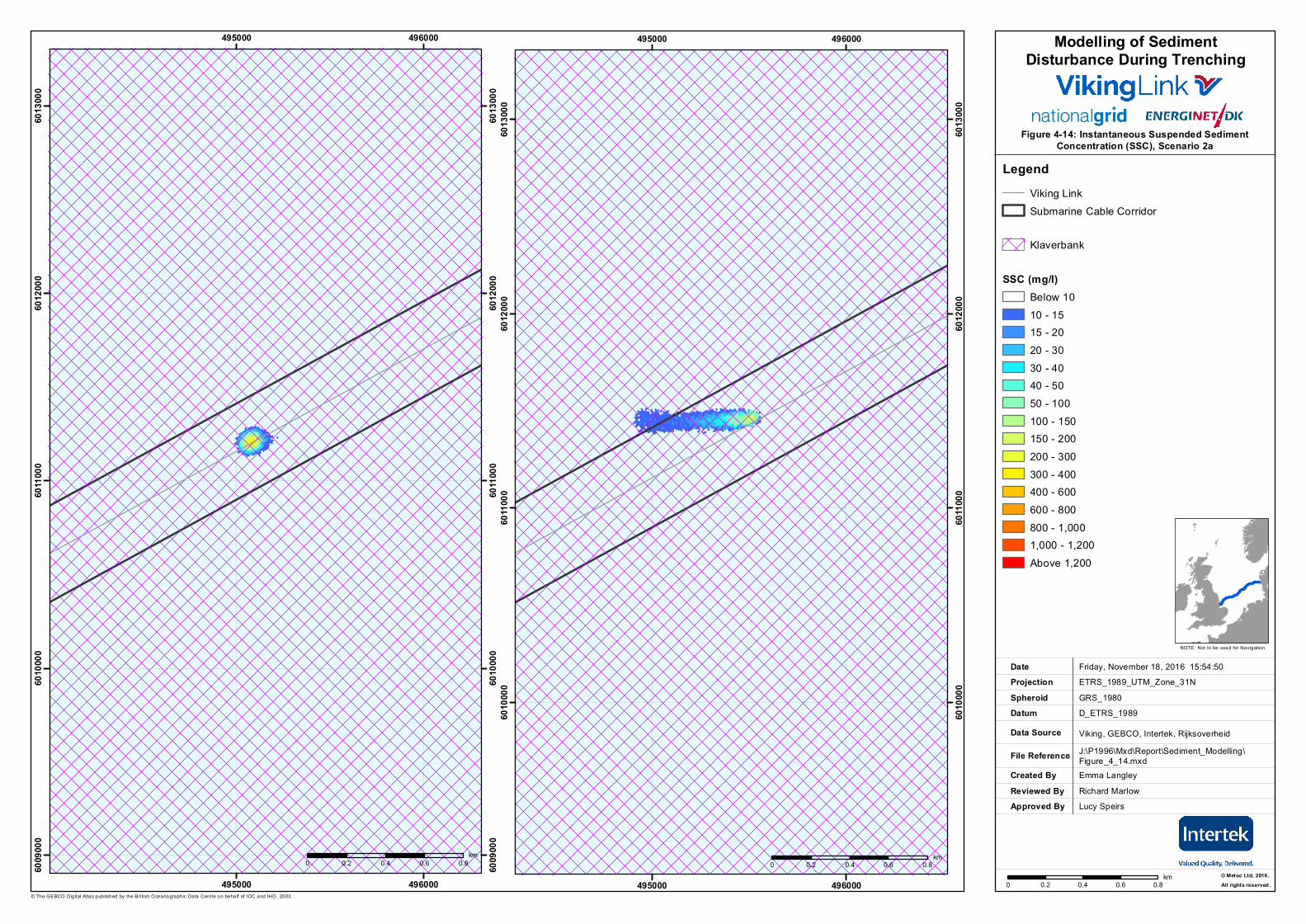
4.4.1.2 Instantaneous SSC, Scenario 2a Figure 4-14 presents close-up images of the sediment discharge at two different points in the tidal cycle. The image on the left presents the SSC distribution during a representative slack tide, whereby the SSC peaks at 356 mg/l at the discharge location, falling to <10 mg/l within the submarine cable corridor (250 m from the cable trench as modelled). The passage of the plough causes SSC to become elevated above background for approximately 30 minutes (Figure 4-15). During stormy conditions, with a typical background value of up to 200 mg/l, elevated SSC may only persist for as little as 10 minutes above background concentrations.
The image on the right presents the plume for sediment discharged one hour later, when the tidal currents are higher. At this snapshot in time, the plume reaches an instantaneous “worst case” in terms of SSC values above 10 mg/l extending beyond the boundary of the submarine cable corridor (250 m from the cable trench as modelled). Peak SSC levels of 180 mg/l at the discharge location and 15 mg/l at the edge of the submarine cable corridor are predicted, with the SSC falling to <10 mg/l approximately 350 m from the cable trench.
.Figure 4-14: Instantaneous Suspended Sediment
Concentration (SSC), Scenario 2a
Created ByReviewed By
Emma Langley
Friday, November 18, 2016 15:54:50ETRS_1989_UTM_Zone_31N
D_ETRS_1989
Viking, GEBCO, Intertek, RijksoverheidJ:\P1996\Mxd\Report\Sediment_Modelling\Figure_4_14.mxd
GRS_1980
DateProjection
DatumData Source
File Reference
Spheroid
NOTE: Not to be used for Navigation
© The GEBCO Dig ital Atlas published by the Bri tish Oceanographic Data Centre on behalf of IOC and IHO, 2003.
Approved By
495000
495000
496000
496000
6009
000
6009
000
6010
000
6010
000
6011
000
6011
000
6012
000
6012
000
6013
000
6013
000
0 0.2 0.4 0.6 0.8km
.
© Metoc Ltd, 2016.All rights reserved.
Richard MarlowLucy Speirs
LegendViking LinkSubmarine Cable Corridor
Klaverbank
SSC (mg/l)Below 1010 - 1515 - 2020 - 3030 - 4040 - 5050 - 100100 - 150150 - 200200 - 300300 - 400400 - 600600 - 800800 - 1,0001,000 - 1,200Above 1,200
Modelling of SedimentDisturbance During Trenching
495000
495000
496000
496000
6010
000
6010
000
6011
000
6011
000
6012
000
6012
000
6013
000
6013
000
0 0.2 0.4 0.6 0.8km0 0.2 0.4 0.6 0.8
km
National Grid Viking Link Ltd and Energinet.dk Modelling of Sediment Disturbance During Trenching of the Proposed Viking Link Interconnector
P1996O_R4158_Rev3 | 3 February 2017 30
Figure 4-15 Variation of SSC as plough passes fixed point along cable trench
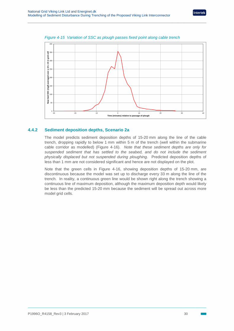
4.4.2 Sediment deposition depths, Scenario 2a The model predicts sediment deposition depths of 15-20 mm along the line of the cable trench, dropping rapidly to below 1 mm within 5 m of the trench (well within the submarine cable corridor as modelled) (Figure 4-16). Note that these sediment depths are only for suspended sediment that has settled to the seabed, and do not include the sediment physically displaced but not suspended during ploughing. Predicted deposition depths of less than 1 mm are not considered significant and hence are not displayed on the plot.
Note that the green cells in Figure 4-16, showing deposition depths of 15-20 mm, are discontinuous because the model was set up to discharge every 33 m along the line of the trench. In reality, a continuous green line would be shown right along the trench showing a continuous line of maximum deposition, although the maximum deposition depth would likely be less than the predicted 15-20 mm because the sediment will be spread out across more model grid cells.
0
50
100
150
200
250
300
350
400
-30 -20 -10 0 10 20 30 40
Nea
r-be
d SS
C (m
g/l)
aver
aged
ove
r a 1
0 x
10 m
grid
cel
l
Time (minutes) relative to passage of plough
.Figure 4-16: Predicted deposition depth (mm), Scenario 2a
Created ByReviewed By
Emma Langley
Friday, November 18, 2016 15:56:34
ETRS_1989_UTM_Zone_31N
D_ETRS_1989
Viking, GEBCO, Intertek, Rijksoverheid
J:\P1996\Mxd\Report\Sediment_Modelling\Figure_4_16.mxd
GRS_1980
DateProjection
DatumData Source
File Reference
Spheroid
NOTE: Not to be used for Navigation
© The GEBCO Dig ital Atlas published by the Bri tish Oceanographic Data Centre on behalf of IOC and IHO, 2003.
Approved By
488000
488000
489000
489000
490000
490000
6008
000
6008
000
6009
000
6009
000
6010
000
6010
000
0 0.1 0.2 0.3 0.4km
.
© Metoc Ltd, 2016.All rights reserved.
Richard Marlow
Lucy Speirs
LegendSubmarine Cable Corridor
Klaverbank
Sediment Deposition Depth (mm)Below 11 - 2
2 - 3
3 - 44 - 6
6 - 88 - 10
10 - 15
15 - 2020 - 25
25 - 3030 - 35
35 - 40
40 - 4545 - 50
Above 50
Modelling of SedimentDisturbance During Trenching
National Grid Viking Link Ltd and Energinet.dk Modelling of Sediment Disturbance During Trenching of the Proposed Viking Link Interconnector
P1996O_R4158_Rev3 | 3 February 2017 32
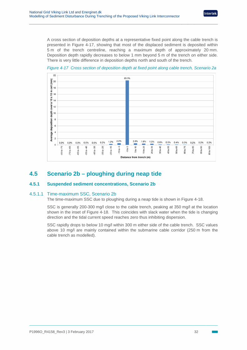
A cross section of deposition depths at a representative fixed point along the cable trench is presented in Figure 4-17, showing that most of the displaced sediment is deposited within 5 m of the trench centreline, reaching a maximum depth of approximately 20 mm. Deposition depth rapidly decreases to below 1 mm beyond 5 m of the trench on either side. There is very little difference in deposition depths north and south of the trench.
Figure 4-17 Cross section of deposition depth at fixed point along cable trench, Scenario 2a
4.5 Scenario 2b – ploughing during neap tide 4.5.1 Suspended sediment concentrations, Scenario 2b
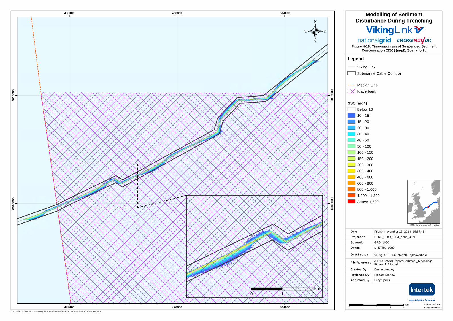
4.5.1.1 Time-maximum SSC, Scenario 2b The time-maximum SSC due to ploughing during a neap tide is shown in Figure 4-18.
SSC is generally 200-300 mg/l close to the cable trench, peaking at 350 mg/l at the location shown in the inset of Figure 4-18. This coincides with slack water when the tide is changing direction and the tidal current speed reaches zero thus inhibiting dispersion.
SSC rapidly drops to below 10 mg/l within 300 m either side of the cable trench. SSC values above 10 mg/l are mainly contained within the submarine cable corridor (250 m from the cable trench as modelled).
.Figure 4-18: Time-maximum of Suspended Sediment
Concentration (SSC) (mg/l), Scenario 2b
Created ByReviewed By
Emma Langley
Friday, November 18, 2016 15:57:45
ETRS_1989_UTM_Zone_31N
D_ETRS_1989
Viking, GEBCO, Intertek, Rijksoverheid
J:\P1996\Mxd\Report\Sediment_Modelling\Figure_4_18.mxd
GRS_1980
DateProjection
DatumData Source
File Reference
Spheroid
NOTE: Not to be used for Navigation
© The GEBCO Dig ital Atlas published by the Bri tish Oceanographic Data Centre on behalf of IOC and IHO, 2003.
Approved By
488000
488000
496000
496000
504000
504000
6008
000
6008
000
6016
000
6016
000
0 1 2 3 4km
.
© Metoc Ltd, 2016.All rights reserved.
Richard Marlow
Lucy Speirs
LegendViking Link
Submarine Cable Corridor
Median Line
Klaverbank
SSC (mg/l)Below 1010 - 15
15 - 20
20 - 3030 - 40
40 - 50
50 - 100100 - 150
150 - 200
200 - 300300 - 400
400 - 600
600 - 800800 - 1,000
1,000 - 1,200
Above 1,200
Modelling of SedimentDisturbance During Trenching
0 1 2km
National Grid Viking Link Ltd and Energinet.dk Modelling of Sediment Disturbance During Trenching of the Proposed Viking Link Interconnector
P1996O_R4158_Rev3 | 3 February 2017 34
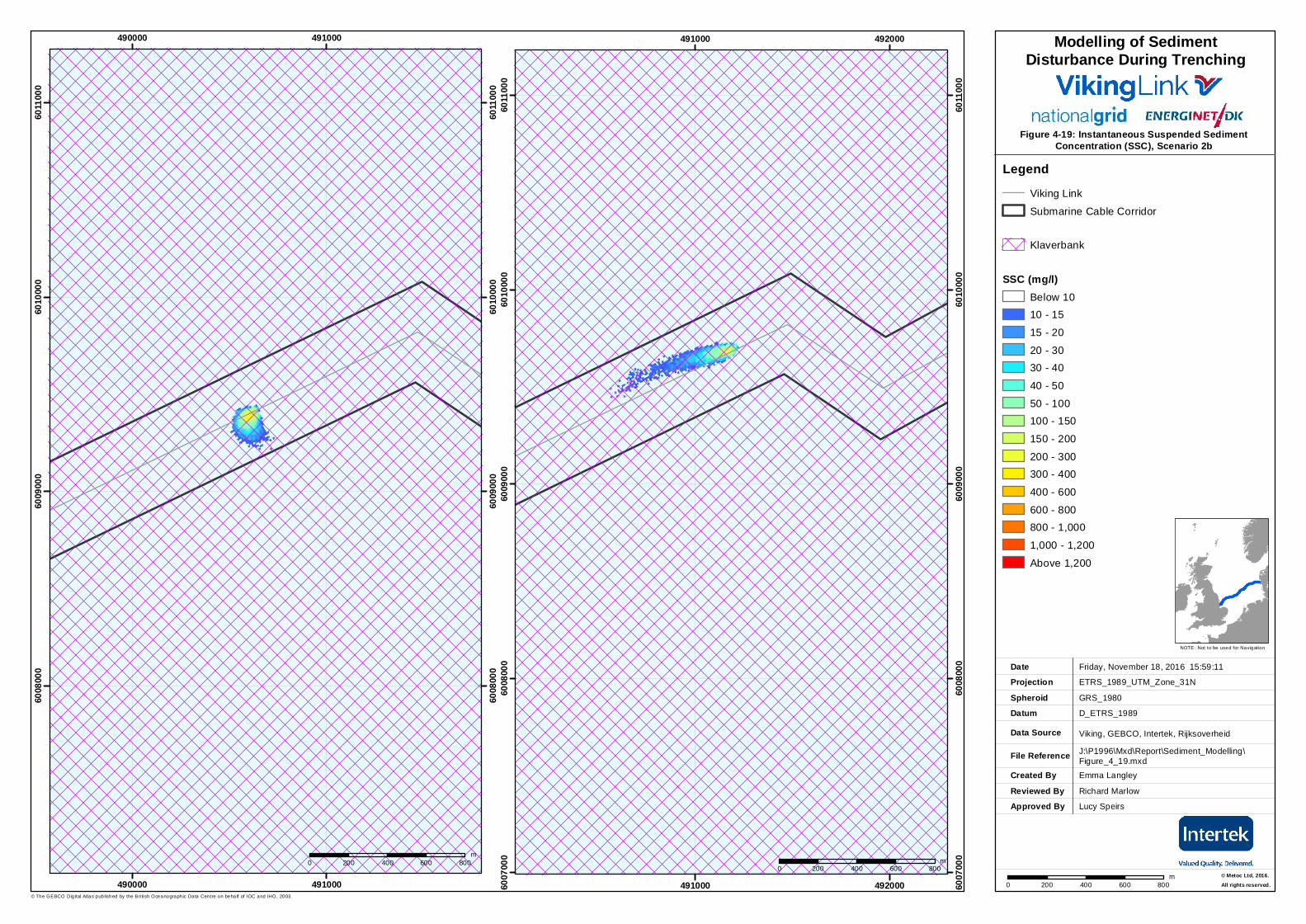
4.5.1.2 Instantaneous SSC, Scenario 2b Figure 4-19 presents close-up images of the sediment discharge at two different points in the tidal cycle. The image on the left presents the SSC distribution during a representative slack tide, whereby the SSC peaks at 328 mg/l at the discharge location, falling to <10 mg/l within the submarine cable corridor (250 m from the cable trench as modelled). The passage of the plough causes SSC to become elevated above background for approximately 30 minutes (Figure 4-20). During stormy conditions, with a typical background value of up to 200 mg/l, elevated SSC may only persist for as little as 10 minutes above background concentrations.
The image on the right presents the plume for sediment discharged two hours later, when the tidal currents are higher. In this case, the model predicts peak SSC levels of 224 mg/l at the discharge location falling to <10 mg/l within the submarine cable corridor (i.e. within 250 m of the cable trench).
.Figure 4-19: Instantaneous Suspended Sediment
Concentration (SSC), Scenario 2b
Created ByReviewed By
Emma Langley
Friday, November 18, 2016 15:59:11
ETRS_1989_UTM_Zone_31N
D_ETRS_1989
Viking, GEBCO, Intertek, Rijksoverheid
J:\P1996\Mxd\Report\Sediment_Modelling\Figure_4_19.mxd
GRS_1980
DateProjection
DatumData Source
File Reference
Spheroid
NOTE: Not to be used for Navigation
© The GEBCO Dig ital Atlas published by the Bri tish Oceanographic Data Centre on behalf of IOC and IHO, 2003.
Approved By
490000
490000
491000
491000
6008
000
6008
000
6009
000
6009
000
6010
000
6010
000
6011
000
6011
000
0 200 400 600 800m
.
© Metoc Ltd, 2016.All rights reserved.
Richard Marlow
Lucy Speirs
LegendViking Link
Submarine Cable Corridor
Klaverbank
SSC (mg/l)Below 1010 - 15
15 - 20
20 - 3030 - 40
40 - 50
50 - 100100 - 150
150 - 200
200 - 300300 - 400
400 - 600
600 - 800800 - 1,000
1,000 - 1,200
Above 1,200
Modelling of SedimentDisturbance During Trenching
491000
491000
492000
4920006007
000
6007
000
6008
000
6008
000
6009
000
6009
000
6010
000
6010
000
6011
000
6011
000
0 200 400 600 800m
0 200 400 600 800m

National Grid Viking Link Ltd and Energinet.dk Modelling of Sediment Disturbance During Trenching of the Proposed Viking Link Interconnector
P1996O_R4158_Rev3 | 3 February 2017 36
Figure 4-20 Variation of SSC as plough passes fixed point along cable trench
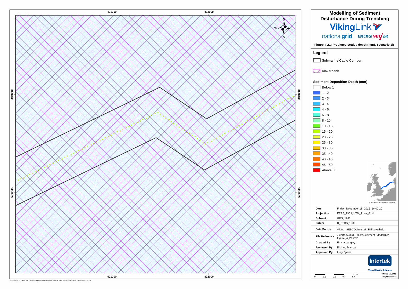
4.5.2 Sediment deposition depths, Scenario 2b The model predicts sediment deposition depths of 15-20 mm along the line of the cable trench, dropping rapidly to below 1 mm within 5 m of the trench (well within the submarine cable corridor as modelled) (Figure 4-21). Note that these sediment depths are only for suspended sediment that has settled to the seabed, and do not include the sediment physically displaced but not suspended during ploughing. Predicted settled depths of less than 1 mm are not considered significant and hence are not displayed on the plot.
Note that the green cells in Figure 4-21, showing deposition depths of 15-20 mm, are discontinuous because the model was set up to discharge every 33 m along the line of the trench. In reality, a continuous green line would be shown right along the trench showing a continuous line of maximum deposition, although the maximum deposition depth would likely be less than the predicted 15-20 mm because the sediment will be spread out across more model grid cells.
0
50
100
150
200
250
300
350
-30 -20 -10 0 10 20 30 40
Nea
r-be
d SS
C (m
g/l)
aver
aged
ove
r a 1
0 x
10 m
grid
cel
l
Time (minutes) relative to passage of plough
.Figure 4-21: Predicted settled depth (mm), Scenario 2b
Created ByReviewed By
Emma Langley
Friday, November 18, 2016 16:00:20
ETRS_1989_UTM_Zone_31N
D_ETRS_1989
Viking, GEBCO, Intertek, Rijksoverheid
J:\P1996\Mxd\Report\Sediment_Modelling\Figure_4_21.mxd
GRS_1980
DateProjection
DatumData Source
File Reference
Spheroid
NOTE: Not to be used for Navigation
© The GEBCO Dig ital Atlas published by the Bri tish Oceanographic Data Centre on behalf of IOC and IHO, 2003.
Approved By
491000
491000
492000
492000
6009
000
6009
000
6010
000
6010
000
0 0.1 0.2 0.3 0.4km
.
© Metoc Ltd, 2016.All rights reserved.
Richard Marlow
Lucy Speirs
LegendSubmarine Cable Corridor
Klaverbank
Sediment Deposition Depth (mm)Below 11 - 2
2 - 33 - 4
4 - 6
6 - 88 - 10
10 - 1515 - 20
20 - 2525 - 30
30 - 35
35 - 4040 - 45
45 - 50Above 50
Modelling of SedimentDisturbance During Trenching
National Grid Viking Link Ltd and Energinet.dk Modelling of Sediment Disturbance During Trenching of the Proposed Viking Link Interconnector
P1996O_R4158_Rev3 | 3 February 2017 38
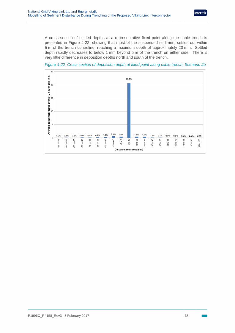
A cross section of settled depths at a representative fixed point along the cable trench is presented in Figure 4-22, showing that most of the suspended sediment settles out within 5 m of the trench centreline, reaching a maximum depth of approximately 20 mm. Settled depth rapidly decreases to below 1 mm beyond 5 m of the trench on either side. There is very little difference in deposition depths north and south of the trench.
Figure 4-22 Cross section of deposition depth at fixed point along cable trench, Scenario 2b
National Grid Viking Link Ltd and Energinet.dk Modelling of Sediment Disturbance During Trenching of the Proposed Viking Link Interconnector
P1996O_R4158_Rev3 | 3 February 2017 39
5. Discussion and Conclusions 5.1 Summary of modelling results
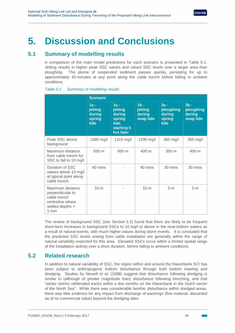
A comparison of the main model predictions for each scenario is presented in Table 5-1. Jetting results in higher peak SSC values and raised SSC levels over a larger area than ploughing. The plume of suspended sediment passes quickly, persisting for up to approximately 40 minutes at any point along the cable trench before falling to ambient conditions.
Table 5-1 Summary of modelling results
Scenario
1a - jetting during spring tide
1a - jetting during spring tide, starting 6 hrs later
1b - jetting during neap tide
2a - ploughing during spring tide
2b - ploughing during neap tide
Peak SSC above background
1580 mg/l 1315 mg/l 1290 mg/l 360 mg/l 350 mg/l
Maximum distance from cable trench for SSC to fall to 10 mg/l
550 m 950 m 400 m 350 m 400 m
Duration of SSC values above 10 mg/l at typical point along cable trench
40 mins - 40 mins 30 mins 30 mins
Maximum distance perpendicular to cable trench centreline where settled depths > 1 mm
10 m - 10 m 5 m 5 m
The review of background SSC (see Section 3.2) found that there are likely to be frequent short-term increases in background SSCs to 10 mg/l or above in the near-bottom waters as a result of natural events, with much higher values during storm events. It is concluded that the predicted SSC levels arising from cable installation are generally within the range of natural variability expected for this area. Elevated SSCs occur within a limited spatial range of the installation activity over a short duration, before falling to ambient conditions.
5.2 Related research In addition to natural variability of SSC, the region within and around the Klaverbank SCI has been subject to anthropogenic bottom disturbance through both bottom trawling and dredging. Studies by Newell et al. (1998) suggest that disturbance following dredging is similar to (although of greater magnitude than) disturbance following trenching, and that “winter storms obliterated tracks within a few months on the Klaverbank in the Dutch sector of the North Sea”. While there was considerable benthic disturbance within dredged areas, there was little evidence for any impact from discharge of washings (fine material, discarded as of no commercial value) beyond the dredging sites.
National Grid Viking Link Ltd and Energinet.dk Modelling of Sediment Disturbance During Trenching of the Proposed Viking Link Interconnector
P1996O_R4158_Rev3 | 3 February 2017 40
As indicated by a recent review of cable installation techniques (BERR, 2008), sediment disturbance during cable installation generally has no negative impact. Of the two available installation techniques, methods using jetting will result in more sediment suspension. Cable installation using jetting during spring tides will result in a wider distribution of suspended fines than would installation at neaps, resulting in higher SSCs across a wider area although deposition depths above 1 mm were only predicted within 10 m of the cable trench for both spring and neap tides. Note that background SSC concentrations are expected to be higher during spring tides.
National Grid Viking Link Ltd and Energinet.dk Modelling of Sediment Disturbance During Trenching of the Proposed Viking Link Interconnector
P1996O_R4158_Rev3 | 3 February 2017 41
1 BERR (2008). Review of cabling techniques and environmental effects applicable to the offshore wind farm industry – Technical report.
2 Chester, R. (1990). Marine geochemistry; Chapman and Hall, London.
3 Fugro (2016). Viking Link Cable Route Survey. Benthic Report: The Netherlands EEZ. Fugro on behalf of National Grid Interconnector Holdings Limited and Energinet.dk.SOV. Document No.: J35045-R-RESE.2(01). Rev 01 (Draft), 17 October 2016.
4 FWR (1993). A framework for marine and estuarine model specification in the UK. Report FR0374. March 1993.
5 Gooding, S., Black, K., Boyde, P. and Boyes, S. (2012). Environmental Impacts of Subsea Trenching Operations. Offshore Site Investigation and Geotechnics: Integrated Technologies – Present and Future, 12-14 September, London, UK.
6 McCave I.N., Hall I.R., Antia A.N., Chou L., Dehairs F., Lampitt R.S., Thomsen L., van Weering T.C.E.,and Wollast R. (2001). Distribution, composition and flux of particulate material over the European margin at 47˚–50˚N. Deep-Sea Research II 48, 3107–3139.
7 Metoc plc (2008). Phase 2 – Anglian Coastal Modelling System – Hydrodynamic Coastal Model Calibration and Validation. Metoc Ltd on behalf of Anglian Water Services. Ref. P805B_RN1738. Final, January 2008.
8 Newell R. C., Seiderer L. J. and Hitchcock D. R. (1998). The impact of dredging works in coastal waters: a review of the sensitivity to disturbance and subsequent recovery of biological resources on the sea bed. Oceanography and Marine Biology: an Annual Review. 36,127-78.
9 Stanev VE Dobrynin M &Andrey Pleskachevsky A & Sebastian Grayek S & Heinz Günther (2008). Bed shear stress in the southern North Sea as an important driver for suspended sediment dynamics. Ocean Dynamics DOI 10.1007/s10236-008-0171-4.
10 UKMMAS (2010). Charting progress 2. Ocean processes, Section 3.7: Suspended particulate matter and turbidity. http://www.gov.scot/Topics/marine/science/atlas/CP2.
References

Viking Link – Contact Us
Great Britain By phone: Freephone + 440800 731 0561 By email: [email protected] By post: FREEPOST VIKING LINK
Denmark By phone: + 45 7010 22 44
By email: [email protected] By post: Energinet.dk, Att. Viking Link, Tonne Kjærsvej
65, DK - 7000 Fredericia