Embed Size (px)
Citation preview
B-1
APPENDIX B. COMPLETE RESPONSES TO ACCOMPLISHMENTS QUESTION

B-3
STATE RESPONSES
• (1) The inspection unit now has access to a servi-lift truck. (2) Emergency repairs were
made to cracks in the steel beams on an Interstate bridge in [the State] as a result of
inspection. (3) A deteriorated superstructure was replaced on an emergency basis in [the
State].
• [The State department of transportation [DOT]] has recently initiated a research project with
the [State university] to evaluate dispersive wave techniques for determining in situ pile
lengths.
• Implemented use of laptop computers and digital cameras for all teams. A sign structure was
removed after inspectors found cracks.
• Inspection routine format and results computerized for consistency and error-checked by
cross-comparison.
• The implementation of a spreadsheet to track priority repairs needed and rehabilitation
completed on bridge elements, followed by the field verification by the inspection team, has
prevented loss of life.
• Bridge program inspections are in Pontis and NBI [National Bridge Inventory]. Laser-based
clearance measuring device.
• (1) Development of observable bridge scour assessment procedure to determine scour
criticality. (2) Development of new inspection forms and electronic data collection process.
(3) Development and implementation of automated permit routing, analysis, permit
[illegible] system to [illegible].
• [State DOT] has a bridge inspector certification program. Team leaders must meet all NBIS
[National Bridge Inspection Standards] requirements in addition to passing a field
B-4
proficiency test. Also, [State DOT] added a Level III NDT [nondestructive testing] inspector
in 1996.
• QC/QA [Quality Control/Quality Assurance] Program is performing very well. Also, all
inspectors are required to complete the NBI Manual 90 course. Fatigue cracking problem on
[Interstate] over [river]. Two-girder system with floor beams (370+ fatigue cracks). Crack
indications in truss pins on Route 11 over [same river]. Alternate support systems added.
• Innovative procedure for nondestructive testing of in-place pins of trusses and pin/hanger
assemblies utilizing ultrasonic inspection equipment.
• Development and implementation of a Bridge Inspection Handbook (contains bridge
inspection policies, procedures, directives). Development and implementation of an
electronic inspection documentation and management system.
• Complete replacement of all pins statewide for pin and hanger details.
• Implementation of [State] roadway information management system. Purchase of laptops,
digital cameras, and color printers for all inspection teams. Evaluated and are using Timber
Decay Detecting Drill. Inspection team found and closed a timber bridge on the State system
that was in danger of collapse.
• A 2-week training course of Bridge Inspectors Training Course in 1997. A safety class and
CPR class for bridge inspection teams. A Stream Stability course in 1998.
• Use of NDE [nondestructive evaluation] to identify a working crack in a trunion shaft of a
major Interstate lift span and successful replacement of the shaft under contract.
• Development of inspector critical finding guideline. Development of inspection frequency
guideline.
B-5
• Improved reporting of inspection results to local agencies. Bridge repair lists placed on
Internet for maintenance crews (with photographs). Using laptop inspection program with
electronic photolog. Load testing of some bridges due to recently re-rating all State bridges.
GIS for bridge database allows graphical depictions on State map of scour critical bridges,
needed inspections, and inspection scheduling.
• Concrete pile PIT testing. Coastal scour hydrology/hydraulic studies. Use of scour
monitoring equipment.
• The State Inspectors using dye-penetrant kits discovered a severe fatigue-cracking problem
that led to a university research project to identify the cause and recommend procedures for
repair. The State NBIS underwater inspectors this past year inspected all State bridges
affected by two natural flood disasters that led to emergency actions to avoid failures due to
scour and erosion. The State implemented a load test program to proof load rate bridges
posted for 1 to 5 tons under legal limit to allow for removing the posting restriction where
practical.
• Use of portable fathometers. Electronic element-level data collection.
• A number of bridges are closed each year based on findings. Underwater inspections have
found threatening conditions twice.
• [State DOT] has implemented the Pontis BMS [bridge management system] with element
inspections. [State DOT] is testing digital cameras and they are using automated inspection
software.
• Implementation of automation software.
• [State DOT] has developed and implemented an Access-based computer program which is
used by their inspectors, engineers, and managers to record inspection findings, to schedule
inspections, and to schedule and track planned maintenance and repairs.
B-6
• Rope-climbing equipment and related training was provided during the last year.
• One inspector is Level III and two inspectors are Level II qualified (ASNT [American
Society for Nondestructive Testing]).
• [Written] QA/QC procedure.
• [State DOT] is supplementing their traditional hydrographic methods by contracting for side-
scan sonar services on those bridges which most concern them.
• Select structures on the Fracture-Critical Master List have been analyzed to determine if they
are, in fact, fracture critical and also identify fracture-critical elements which should receive
more in-depth inspections.
• [State DOT] recently got back on a 2-year schedule.
• All bridge inspectors are certified in Red Cross First Aid and CPR. All bridge inspectors are
scuba certified for underwater inspections.
• NDE technologies are being used on pin/hanger connections. Consultant has been hired to
perform the evaluations.
• [State DOT] uses rope-climbing techniques and equipment to inspect some bridges.
COUNTY RESPONSES • Identifying areas of advanced decay or scour and closing the bridges to traffic until repaired.
• Changing over to Pontis bridge inspection techniques.
B-7
• Identified corrosion and subsequent settlement of a steel-beam bridge. Closed, repaired, and
reopened bridge and finally constructed a new structure. Identified settlement in timber piles
and corrected.
• Completed bridge scour rating on all bridges.
• Timely identification of bridges needing posting and/or closure.
• In 1995, [County DOT] noticed abutment problems on a wood trestle bridge. In 1996, when
new bridge was under construction at new location, the abutment of the old bridge failed.
• Started using a new and more thorough field inspection form in the last 2 years.
• Develop repair list. Broken down by in-house or contractor and priority.
• Reporting of damaged bridge components. Inspection interval of every 2 years or more
frequently if bridge warrants such.
• Identifying areas of advanced decay or scour, and closing the bridges to traffic.
• Developing a computerized bridge inspection inventory program.
• Removed 6 ft2 of AC [asphalt concrete] overlay & partially removed concrete deck to expose
rusted rebar on 28-ft by 610-ft bridge. Scheduled deck for replacement. [County DOT] has
re-analyzed all timber and I-beam bridges, resulting in posting of 40 bridges.
• Compliment from FHWA [Federal Highway Administration] bridge inspector regarding
problem bridges being scheduled into the DOT budget and program.
B-8
• [County DOT] has found major problems with three bridges carrying gravel roads over
railroad tracks. [County DOT] has removed two and replaced them with at-grade crossings.
[County DOT] regraded the roads and paid all expenses for the change.
• Scour-Critical.
• Enrollment of inspector in NHI [National Highway Institute] Bridge Inspection courses in
Spring of 1999.
• Bridges are inspected on an almost daily basis by [County] truck drivers, motor patrol
operators, and farmers. Reporting observed deficiencies of railings, signs, loss of backfill,
etc.
• Annually, potential problems are discovered and addressed. [County DOT] has many bridges
from 1800’s.
• Bridges have been closed or severely limited to weight after inspections have discovered
critical problems.
C-1
APPENDIX C. ADVANCE INFORMATION PACKAGE

C-3
Re: Visual Inspection Investigation Advance Information Package DTFH61-96-C-00054 Refer to: HRDI
Dear Sir or Madam:
The purpose of this information package is to provide you with some important information in advance of your on-site participation in the Federal Highway Administration’s Nondestructive Evaluation Validation Center Visual Inspection study. There are a few pieces of information that we want to bring to your attention. First, enclosed please find information regarding one of the tasks you will be completing. One of the tasks you will be asked to perform is the Routine Inspection of a low-volume bridge in accordance with your State procedures. To complete this task, it will be necessary for each inspector to review your State procedure for conduct of a Routine Inspection, and to generate all forms required for such an inspection. Additionally, you will find information related to the equipment that should be brought and what equipment will be provided. Also enclosed is information related to your schedule of on-site tasks and accommodations. We would like to thank you in advance for your participation in this very important study. Your assistance will allow us to establish the current state of the bridge inspection practice. If you have any questions about the enclosed materials or about your visit in general, please feel free to contact me at (202) 493-3121 or via email at [email protected]. If you have questions about your travel arrangements you should contact Ms. Fariba Parvizi at (202) 493-3118. Once again, thank you for your interest in the Nondestructive Evaluation Validation Center Visual Inspection study. Sincerely,
NDE VALIDATION CENTER
Brent M. Phares Research Engineer BMP:eg Encl.

C-5
Summary of Items Included with this Package: • General Information for Visual Inspection Study • Map to TFHRC • Sample Data forms for a Routine Inspection • Plans for Van Buren Rd. Bridge (pages 10-13) • Sample Travel Expense Voucher Checklist to do before Visit: �� Indicate Originating Airport to Ms. Parvizi (if not coming by car). �� Send to the NDEVC a copy of a typical inspection form used by your DOT for the NBIS inspections.
Please send this form in advance to: NDE Validation Center 6300 Georgetown Pike McLean, VA 22101 Attn: Dr. Brent Phares.
�� Receive Confirmation Letter with hotel information and confirmation numbers, telephone numbers, maps, and meeting information.
�� Bring Personal Safety Equipment (Safety shoes, safety glasses, gloves, and other protective clothing). �� Bring Forms required to perform your State’s normal NBIS inspection for the Van Buren Rd. Bridge.

C-7
Visual Inspection Study
Information Packet
Federal Highway Administration U.S. Department of Transportation Turner-Fairbank Highway Research Center 6300 Georgetown Pike McLean, Virginia 22101 :LVV��-DQQH\��(OVWQHU�$VVRFLDWHV��,QF�� Engineers, Architects, Material Scientists 225 Peachtree Street, N.E., Suite 1600 Atlanta, Georgia 30303 (404) 577-7444 fax: (404) 577-0066
:-(�
C-8
GENERAL INFORMATION FOR NDE VALIDATION CENTER VISUAL INSPECTION STUDY
The goal of the study of Visual Inspection is to assess Visual Inspection as applied to highway bridges. To accomplish this, the NDE Validation Center (NDEVC) will use a cross-section of bridge inspectors to perform eleven different inspection tasks consisting of both Routine Inspection and In-Depth Inspection techniques. Most inspection tasks will be performed individually, but for safety and the sake of the experiment, each visiting inspector will be teamed with an observer from the NDE Validation Center. It is important to remember throughout your participation that we are not “testing” individual inspectors. The purpose of the study is to evaluate the overall effectiveness of the visual inspection process. Anonymity of each inspector will be ensured by the use of randomly generated inspector numbers to track data. Ten of the eleven tasks involve individual inspectors performing Routine or In-Depth Inspections. The other task is team oriented; designed to observe normal State inspection practices without any guidance from the observers. This last task will require some advance preparation, and more information is presented in a separate section below. As part of this task, please send to the NDEVC (prior to your visit) a copy of a typical inspection form used by your inspection department for Routine Inspection. Testing will be performed in three areas: • Routine Inspections • In-Depth Inspections • Inspector characterizations Data will be collected in four forms: • Lab testing (vision testing and written questionnaire) • Oral questionnaires before and after each task • Observations recorded by the observer during the inspection • Data forms for the inspection report To ensure that all of the inspectors use consistent terms, and understand exactly what will be expected, the following will provide some specific definitions for the Visual Inspection study. Task Definitions Routine Inspection The AASHTO Manual for Condition Evaluation 1994 defines Routine Inspection as:
… a regularly scheduled inspection consisting of observations and/or measurements needed to determine the physical and functional condition of the bridge, to identify any changes from ‘Initial’ or previously recorded conditions, and to ensure that the structure continues to satisfy present service requirements. The Routine Inspection must fully satisfy the requirements of the National Bridge Inspection Standards with respect to maximum inspection frequency, the updating of Structure Inventory and Appraisal data and the qualifications of the inspection personnel. These inspections are generally conducted from the deck; ground and/or water levels, and from permanent work platforms and walkways, if present. (AASHTO Manual, pgs 11-12).

C-9
We will be using the above definition in our study. The Routine Inspection appears to be the typical inspection used to satisfy NBIS inspection requirements. In order to conserve time, certain aspects of the typical NBIS inspection will be omitted from the inspections performed in this study. Some of the things that will be excluded from the inspections include: underwater stream profiles, gross dimension checks, and certain non-structural items like approach barriers, guardrails, and vertical clearance. It is important for consistency within the experiment that the test bridges remain in the same condition throughout the experiment. As such, invasive procedures, even as small as chipping existing paint or brushing away dirt, will not be allowed. We ask that where these invasive procedures would be used in the experiment, that the inspector make a brief notation about what would normally be done, and where. A sample of the data sheets to be used for this experiment is included with this packet. In-Depth Inspection The AASHTO Manual for Condition Evaluation 1994 defines In-Depth Inspection as:
… a close-up, hands-on inspection of one or more members, above or below the water level to identify any deficiency(ies) not readily detectable using Routine Inspection procedures. Traffic control and special equipment, such as under-bridge inspection equipment, staging and workboats, should be provided to obtain access, if needed. (AASHTO Manual, pg. 12).
We will be using this definition for our study. Access equipment will be provided where required to reach the superstructure. For two of these tasks, a boom lift will be used to access the superstructure. Again, members will not be inspected below the water level. When needed, traffic control will be arranged by the NDEVC. The individual tasks will define exactly what members are to be inspected. It is essential for the experiment that the test bridges remain in exactly the same condition throughout the experiment. As such, invasive procedures, even as small as chipping existing paint or removing dirt, will not be allowed. We ask that where these invasive procedures would be used in the experiment, that the inspector notifies his observer what would be done, and where. Rating System A rating system will be used that is very similar to the NBIS provisions. Although element-level, PONTIS-type inspections are typically performed by many states, this study will use the NBIS system for uniformity. This system uses a ranking of 0-9 to describe condition. For consistency, we ask that this rating system be used, with the definitions provided below.
N NOT APPLICABLE 9 EXCELLENT CONDITION 8 VERY GOOD CONDITION – no problems noted. 7 GOOD CONDITION – some minor problems. 6 SATISFACTORY CONDITION – structural elements show minor deterioration. 5 FAIR CONDITION – all primary structural elements are sound but may have minor section loss,
cracking, spalling, or scour. 4 POOR CONDITION – advanced section loss, deterioration, spalling, or scour. 3 SERIOUS CONDITION – loss of section, deterioration, spalling or scour have seriously affected
primary structural components. Local failures are possible. Fatigue cracks in steel or shear cracks in concrete may be present.
C-10
2 CRITICAL CONDITION – advanced deterioration of primary structural elements. Fatigue cracks in steel or shear cracks in concrete may be present or scour may have removed substructure support. Unless closely monitored it may be necessary to close the bridge until corrective action is taken.
1 “IMMINENT” FAILURE CONDITION – major deterioration or section loss present in critical structural components, or obvious vertical or horizontal movement affecting structure stability. Bridge is closed to traffic but corrective action may put bridge back in light service.
0 FAILED CONDITION – out of service; beyond corrective action. Items provided during visit Where vertical access is required, ladders, scaffolding, or lifts will be provided. An inspector’s tool bag will also be provided, and will include:
• Clipboards • Flashlights • Masonry hammer (for sounding purposes only) • Chain • Measuring tapes • Binoculars • Plumb bob • String • Small clamps
In order to preserve identical conditions for all inspectors, the use of inspection picks and jackknives is not allowed. Safety harnesses, traffic vests, and hard hats will be provided by the NDEVC. Items to bring Normal attire appropriate for bridge inspections is expected. Personal safety equipment is expected to be provided by the individual inspectors, including safety shoes, glasses, gloves, and other personal protective clothing.
C-11
ADVANCE INFORMATION FOR TASK 3 One of the tasks that each inspector will be asked to perform is the Routine Inspection of a low (less than 50) ADT bridge. In the overall Visual Inspection Scope of Work, this Routine Inspection is called Task 3. Again, the AASHTO Manual for Condition Evaluation 1994 defines a Routine Inspection as:
…a regularly scheduled inspections consisting of observations and/or measurements needed to determine the physical and functional condition of the bridge, to identify any changes from ‘Initial’ or previously recorded conditions, and to ensure that the structure continues to satisfy present service requirements.” (AASHTO Manual, pg 12).
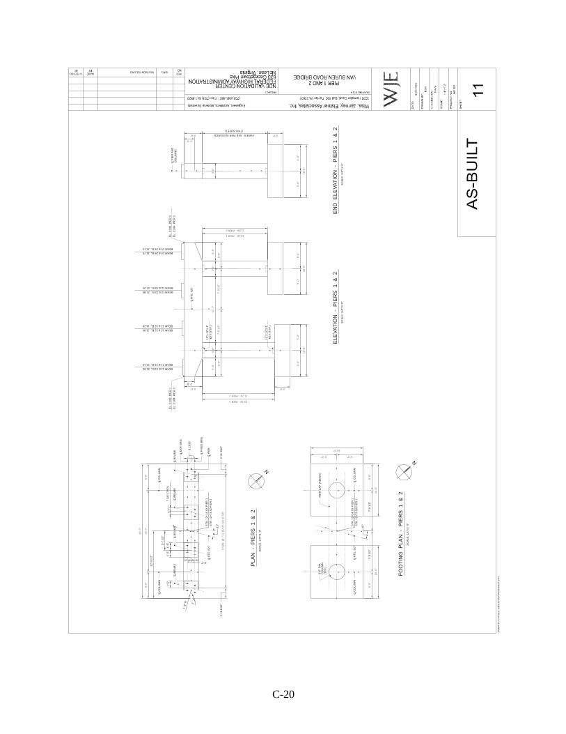
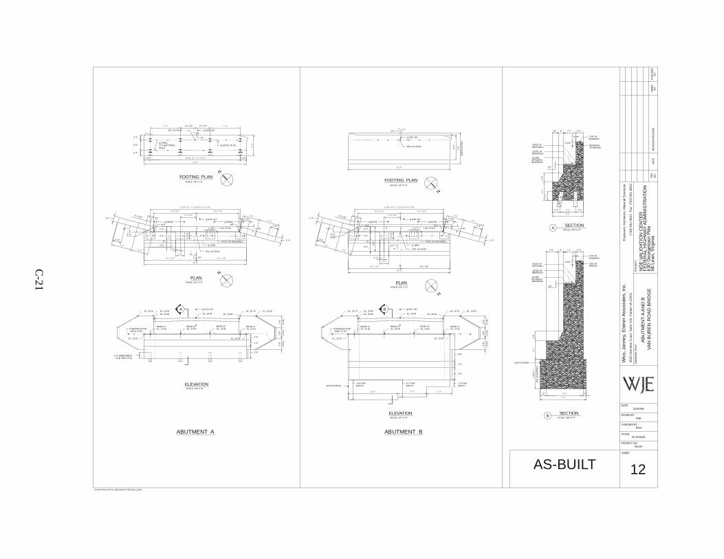
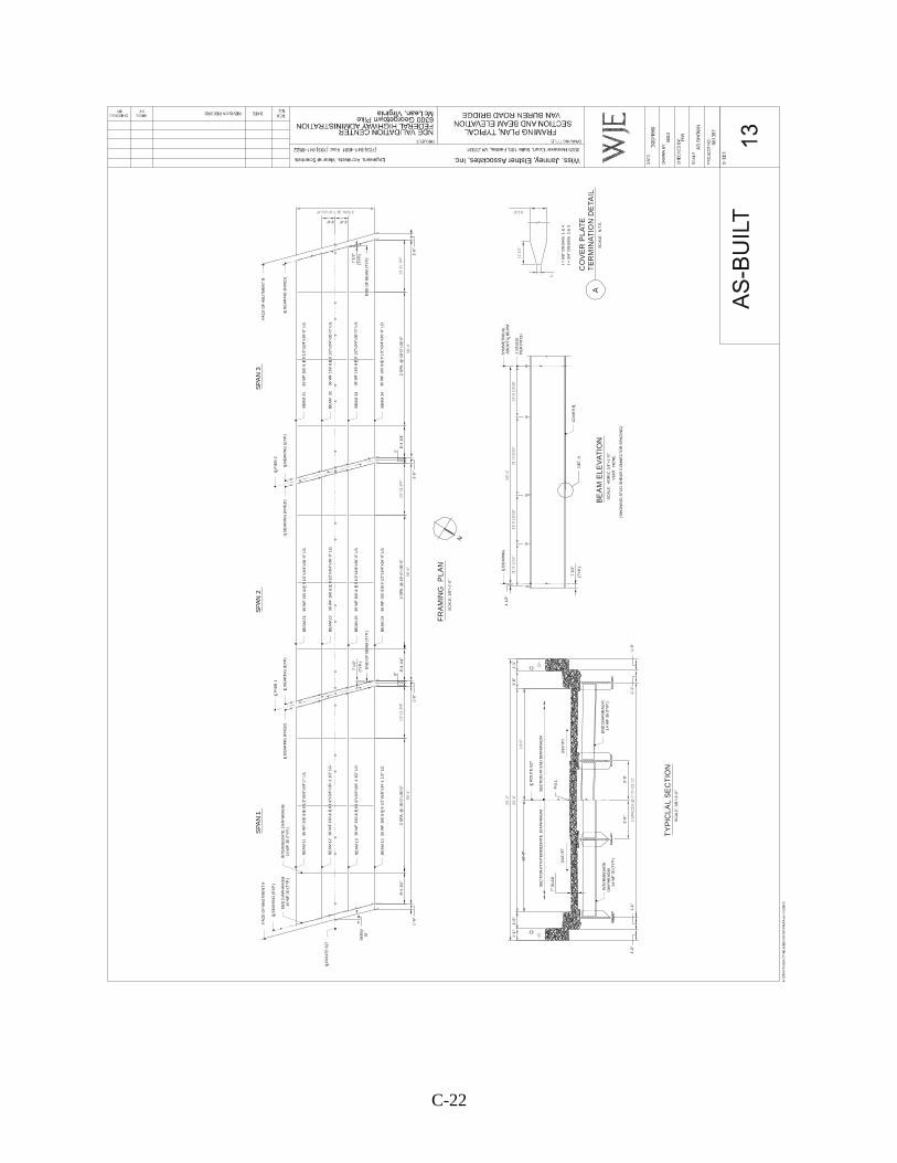
The objective of this task is to observe differences in the States’ inspection procedures. Included with this package is a set of plans (labeled pages 10-13) for the bridge to be inspected as part of Task 3, and the NBIS coding information from a previous inspection. Your team will be asked to perform your agency’s routine state inspection on this bridge, with no input from the observers. At the conclusion of the inspection, the NDEVC would like a copy of the field report. IMPORTANT : Please plan and prepare for this inspection as if it was a bridge in your State and part of your normal inspection workload. Generate in advance any forms that would be required to complete an inspection report in your State’s format, keeping in mind that you will be asked to submit a final hard copy report. Bridge description: The Van Buren Road Bridge over the Quantico Creek was built around 1960, and consists of three spans, each simply supported with a span length of approximately 60 ft. The overall bridge length is 182-ft 7-in. with an overall width of 28-ft 0-in. The deck is 7-in.-thick cast-in-place reinforced concrete supported by four wide-flange stringers, which act compositely with the deck. The steel stringers are reinforced with tapered-end, welded, cover plates. The superstructure is supported by reinforced concrete piers and abutments founded on spread footings or steel H-piles. The bridge was designed for HS5-44 loading. Items to bring Normal attire appropriate for bridge inspections is expected. Safety shoes, glasses, gloves, and other personal protective clothing will be expected. (Safety vests and hard hats will be provided by the NDEVC.) If laptop computers or digital cameras are used for normal routine inspections, please bring these items along if possible. Items provided Ladders will be provided to access the superstructure. An inspector’s tool kit will be provided for use during the inspections, and will include:
• Clipboards • Flashlights • Masonry hammer • Chain • Measuring tapes • Binoculars • Plumb bob • String • Small clamps
C-12
Please refrain from bringing other inspection tools. In order to preserve identical conditions for all inspectors, the use of inspection picks and jackknives cannot be allowed. Traffic vests and hard hats will be provided by the NDEVC. As mentioned above, if portable computers or digital cameras are used in the normal inspection process, please bring these items.
C-13
SCHEDULE Activities are planned for a 2-½ day period. The schedule is organized to account for groups arriving in the Washington Metro area before 1 pm or after 1 pm. Those due to arrive before 1 pm should take a shuttle (Supershuttle, Washington Flyer, etc.) to our facilities, and the inspection program will commence that same day. Those due to arrive after 1 pm will be expected to take a shuttle to the hotel, and Day 1 of the inspection program will commence the following day after lunch. In the second scenario, we will plan to pick you up at your hotel at approximately 12:15 pm. Our facilities are at the Turner-Fairbank Highway Research Center (TFHRC) at 6300 Georgetown Pike, in McLean, VA. A map is included for your use. Day 1 of the inspection program will be conducted at the NDEVC at TFHRC, followed by travel to Breezewood, Pennsylvania. Hotel rooms will be arranged by the NDEVC. Day 2 of the inspection program will take place at the Pennsylvania Turnpike Commission’s Safety Testing and Research (STAR) Facility in Breezewood. Following these tasks, we will return to Northern Virginia. Once again, hotel rooms will be arranged by the NDEVC. Day 3 of the inspection program will take place at two bridges in Northern Virginia. At the conclusion of testing, the visiting inspectors will be returned either to the hotel or to the airport, depending on travel arrangements. Schematic schedules of tasks are presented below. Schematic Schedule for inspectors arriving to the Washington Metro area before 1 pm. Day 1 Day 2 Day 3 Morning Arrive at TFHRC.
Finish preparations for Task 3.
Star Facility – Morning Inspection tasks.
Rt. 1 test bridge.
Afternoon TFHRC NDEVC Lab: Introduction and preliminary inspector characterization. Travel to STAR Facility (PA).
Star Facility – Afternoon inspection tasks. Travel to No. Va.
Van Buren Rd. test bridge.
Schematic Schedule for inspectors arriving to the Washington Metro area after 1 pm. Travel Day Day 1 Day 2 Day 3 Morning Travel Finish preparations
for Task 3. Star Facility – Morning Inspection tasks.
Rt. 1 test bridge.
Afternoon Arrive Northern Virginia, take shuttle to hotel.
TFHRC NDEVC Lab: Introduction and preliminary inspector characterization. Travel to STAR Facility (PA).
Star Facility – Afternoon inspection tasks. Return to No. Va.
Van Buren Rd. test bridge.

C-14
Sample Data Form
C-15
C-16
C-17
C-18
Plans for Van Buren Road Bridge
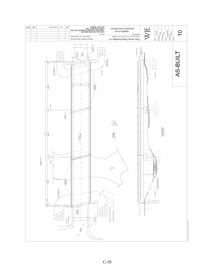
C-19
N
PLA
N
SC
ALE
: 1/8
"=1’
-0"
SP
AN
1S
PA
N 2
SP
AN
3
BE
GIN
NIN
GO
F B
RID
GE
STA
.11+
52.7
1
EN
D O
F B
RID
GE
STA
.13+
35.2
5
FAC
E O
F A
BU
TM
EN
T A
AT
C
FA
CE
OF
AB
UT
ME
NT
BA
T C
SC
ALE
: 1/
8"=1
’-0"
ELE
VAT
ION
ST
EE
L P
ILE
S
CO
NC
RE
TE
SLA
B/R
IP-R
AP
SLO
PE
PR
OT
EC
TIO
N (
TY
P.)
SU
B-F
OO
TIN
G
CO
NC
RE
TE S
LAB
SLO
PE
PR
OTE
CT
ION
FIN
ISH
ED
GR
AD
E
(FE
B. 1
998
)E
XIS
TIN
G P
RO
FIL
E
GU
AR
D R
AIL
SO
FT
SH
OU
LDE
R
AS
PH
ALT
PAV
EM
EN
T
SO
FT
SH
OU
LDE
R
GU
AR
D R
AIL
C Q
UA
NTI
CO
CR
EE
K(F
EB
. 199
8)
L
ED
GE
OF
AS
PH
ALT
PAV
EM
EN
T
AS
PH
ALT
PAV
EM
EN
T
SK
EW
15%
%D
00’
00"
2’-0"
LC R
OU
TE 6
27
C P
IER
2L
C P
IER
1L
EX
P.FI
X.
EX
P.F
IX.
EX
P.F
IX.
RIP
-RA
P S
LOP
E P
RO
TE
CTI
ON
TO
E O
F S
LOP
E
L
L
1" P
RE
FO
RM
ED
JOIN
T F
ILLE
R E
XPA
NS
ION
1"
PR
EF
OR
ME
D
JOIN
T F
ILLE
R E
XPA
NS
ION
RTE
. 627
RT
E. 6
27
(VA
N B
UR
EN
RO
AD
)
FLOW
CO
NC
RE
TE
SL
AB
SLO
PE
PR
OTE
CT
ION
1’-3
1/2
"60
’-7"
59’-1
0"
60’-7
"1’
-3 1
/2"
183
’-7 1
/16"
10’-0"10’-0"
20’-0"
17’-0"1’-0"
2’2’
16’-0"
12’-6"
C-20
ELE
VA
TIO
N -
PIE
RS
1
& 2
EL
. 21
.84
P
IER
2
EL
. 21
.68
P
IER
1
BEAM 11 & 21 EL. 21.81
C R
TE
. 62
7L
12"x
12"
x 4
"K
EY
(T
YP
.)
12"x
12"
x 4
"K
EY
(T
YP
.)
SC
AL
E: 1
/4"=
1’-0
"
LC R
TE
. 6
27
STA
. 12+
73
.92-
PIE
R 2
STA
. 12+
14
.XX
-PIE
R 1
SC
AL
E:
1/4
"=1
’-0"
FO
OT
ING
PLA
N
- P
IER
S 1
& 2
N
PLA
N -
PIE
RS
1
& 2
SC
AL
E: 1
/4"=
1’-
0"
N
3’-0
" D
IA.
PIE
R C
AP
(A
BO
VE
)
STA
. 12+
14
.XX
-PIE
R 1
STA
. 12+
73
.92-
PIE
R 2
C R
TE
. 6
27
L
C B
EA
MS
LC
BE
AM
SL
C B
EA
MS
LC
BE
AM
SL
15
°
LC E
XP.
BR
G.
C F
IXE
D B
RG
.L
LC P
IER
C C
OL
UM
NL
C C
OL
UM
NLC C
OL
UM
NL
LC C
OL
UM
N
SC
AL
E:
1/4
"=1
'-0"
EN
D E
LEVA
TIO
N
- P
IER
S 1
&
2
C P
IER
AN
DL CO
LU
MN
S
CO
LUM
N(T
YP
.)
EL
. 21
.68
P
IER
1
EL
. 21
.84
P
IER
2
BEAM 21 & 31 EL. 21.19
BEAM 22 & 32 EL. 21.20
BEAM 12 & 22 EL. 21.90
BEAM 13 & 23 EL. 21.88
BEAM 23 & 33 EL. 21.26
BEAM 14 & 24 EL. 21.75
BEAM 24 & 34 EL. 21.13
3’-6" 3’-0"
5'-0
"5
'-0"
5'-
0"5'
-0"
5'-0
"5
'-0"
10'
-0"
10'-
0"
2’-0"
3’-6" 3’-0"
13.76’ - PIER 1
11.74’ - PIER 2
3'-
6"3'
-0"
12
'-7"
3'-0
"3
'-6"
5'-0
"7'
-9 1
/2"
7'-9
1/2
"5'
-0"
12.46’ - PIER 1
11.54’ - PIER 2
2’-0"
5'-0
"5'
-0"
10'
-0"
10'
-0"
5’-0"5’-0"
10’-0"
15°
5’-0
"1
5’-7
"5’
-0"
25
’-7"
3 S
PA. @
7’-2
15
/16"
=2
1’-8
7/8
"
3’-7
1/2
"
3’-0
"
7’-9
1/2
"7’
-9 1
/2"
10’-0
"
1’-5
"1’
-5"
1’-5
"7
3/4
" (T
YP
.)
8 11
/16
"
1’-6
" R
.
2"
1’-4"
1’-1
1 1/
16
"
12
’-9 1
/2"
1’-
11 1
/16
"
VARIES - SEE PIER ELEVATION
(THIS SHEET)
C
-21
12’-7 1/2"
2’-2"
5’-0
"
5’-0"
4’-0"
4’-0"
5’-0"
3’-10 3/4’
10’-4 1/4" 10’-4 1/4"
3 SPA. AT 7’-2 15/16"=21’-8 7/8"
7’-3" 7’-3"
3 SPA. @ 7’-3"=21’-9"
5’-0
"
3 SPA. AT 7’-2 15/16"=21’-8 7/8"
10’-4 1/4"
12’-7 1/2"
4’-0"
5’-0"
5’-0"
10’-4 1/4"
3’-10 3/4’ 4’-0"
12’-0" 7’-0" 6’-3"
12’-1 1/2"
24’-9"
24’-9"
24’-9"
24’-9"
2’-6"
5’-0"
2’-3
"
3’-0
’
2’-0"
6’-0"
7’-6"
VA
RIE
S
2’-0"
3’-0
"
2’-2"
PLANSCALE: 1/4"=1’-0"
N
STA. 11+54.00
C RTE. 627LC BEAML
15°
C BRG.L
N
15°
W.P. W.P.C BEAML
15°
STA. 11+54.00 L
C STEEL PILESL
C RTE. 627
15°
LC STEEL 2:12 BATTEREDPILES
FOOTING PLANSCALE: 1/4"=1'-0"
N
W.P.15°
STA. 13+34.00
C BEAMLC RTE. 627L
C BEAML
W.P.15°
LC RTE. 627
15°
N
STA. 13+34.00
SCALE: 1/4"=1'-0"
ELEVATION
ABUTMENT A
LC RTE. 627
FACE OF BACKWALL
C BRG.L
FACE OF BACKWALL
A
ABUTMENT B
ELEVATIONSCALE: 1/4"=1'-0"
B C RTE. 627L
SCALE: 1/4"=1'-0"
FOOTING PLAN
SCALE: 1/4"=1'-0"
PLAN
A
B
SCALE: 3/8"=1'-0"
SECTION
SCALE: 3/8"=1'-0"
SECTION
BEGINING OF BRIDGE
BRIDGEEND OF
15°1'-0"
9"
2'-0"
1'-3"
6" R.
(TY
P.)
2’-4 1/4"
2’-0"
2’-0"
1'-3"
1'-3"
1’-1
0"
7 3/4" (TYP.)
1'-3"
1'-6"
2'-6"
1'-3"
1'-3"
9"
2'-0"
1'-3"2’-4 1/4"
2’-0"(TYP.)
6" R.
2’-0"7 3/4" (TYP.)
1’-1
0"
1'-3"
SU
B-F
OO
TIN
G
EL. 25.90EL. 26.65EL. 26.75
EL. 26.05EL. 26.70 EL. 25.90
EL. 22.49 EL. 22.51EL. 22.39 EL. 22.42
EL. 22.20
BEAM 14 BEAM 13 BEAM 12 BEAM 11
1'-6" EMBEDMENTL
1'-4"
1'-6"
3'-0"
2’-9
"2’
-8"
2’-9
"
(TY
P.)
(TY
P.)
CONSTRUCTIONJOINT (TYP.)
EL. 25.95
EL. 22.20
JOINT (TYP.)CONSTRUCTION
SUB-FOOTING
EL. 22.20
EL. 22.42
EL. 26.70
BEAM 11EL. 22.49BEAM 13
EL. 22.39
EL. 26.65EL. 25.90
BEAM 14
EL. 26.75
EL. 22.51BEAM 12
EL. 26.05
EL. 22.20
EL. 25.95
3'-0"
EL. 25.90
1'-6"
6'-6"
(TY
P.)
2’-9
"2’
-9"
(TY
P.)
2’-8
"
(TY
P.)
1.67' AVE.4.17' AVE.DEPTH4.83' AVE.
DEPTH DEPTH
3'-7 1/2" 3'-7 1/2"
1'-6"
1’-10"1’-10"
1'-3" 1'-3"
1’-6
"
1/2"
12" 9" 1'-3"
1"
6 3/4"
12" 6"
2'-0" 1'-3"9"
1"
6 3/4"
1/2"
1’-6
"
SE
E E
LEV
ATIO
N
TOP OF ROADWAY
TOP OF ROADWAY
FACE OFBACKWALL
BEARINGSLEVEL AT
BETWEENSLOPE
BEARINGS
BEARINGS
BEARINGSBETWEENSLOPE
LEVEL AT
BACKWALLFACE OF
SUB-FOOTING
6’-0
"
7’-6
"
AT C PILE (TYP.)
1'-1"
12'-1 1/2"
6’-0
"
2'-0"1'-1"
1'-0"
1'-0"
VA
N B
UR
EN
RO
AD
BR
IDG
E
Wis
s, J
an
ney,
Els
tner
Ass
ocia
tes,
Inc.
3025
Ham
aker
Cou
rt, S
uite
100
, Fai
rfax
VA
220
31
H:\DRAFTING\ACTIV E JOBS \961387-FHWA\asb12.DWG
PROJECT NO:961387
SHEET:
DATE:
CHECKED BY:
AS SHOWN
RAW
SCALE:
BSB
3/20/1998
DRAWN BY:
AB
UT
ME
NT
A A
ND
B
DR
AW
ING
TIT
LE:
RE
VIS
ION
RE
CO
RD
FE
DE
RA
L H
IGH
WA
Y A
DM
INIS
TR
AT
ION
(703
) 64
1-46
01
Fax
: (70
3) 6
41-8
822
ND
E V
AL
IDAT
ION
CE
NT
ER
Eng
inee
rs, A
rchi
tect
s, M
ater
ial S
cien
tists
M L
ea
n, V
irgin
ia6
30 G
eor
geto
wn
Pik
e
PR
OJE
CT:
cD
ATE
NO
.R
EV
.C
HE
CK
ED
MA
DE
BY
BY
AS-BUILT 12
C-22
N
FR
AM
ING
PL
AN
S
CA
LE: 1
/8"=
1’-0
"
SP
AN
1S
PA
N 2
SP
AN
3
TY
PIC
LA
L S
EC
TIO
NS
CA
LE:
3/8
"=1’
-0"
SC
ALE
: H
OR
IZ. 1
/4"=
1’-0
"
BE
AM
EL
EV
AT
ION
VE
RT.
N
ON
E
(SH
OW
ING
ST
UD
SH
EA
R C
ON
NE
CT
OR
SP
AC
ING
)
TE
RM
INA
TIO
N D
ETA
ILS
CA
LE:
N.T
.S.
CO
VE
R P
LA
TE
t = 5
/8"
ON
BM
S. 1
& 4
t = 3
/4"
ON
BM
S. 2
& 3
A
20’
-0"
25’
-2"
10’
-0"
3 S
PA
CE
S @
7’-0
"=21
’-0"
11’-4
1/1
6"13
’-0 1
5/16
"21
’-0 3
/16"
13’-6
13/
16"
58’
-4"
8’-4
1/4
"8’
-4 1
/4"
8’-4
1/4
"
3’-6"3’-6"
1’-6
"1
’-6"
1’-6
"1’
-6"
9"
C B
EA
RIN
G (
EX
P.)
L
C B
EA
RIN
G (
EX
P.)
LLC B
EA
RIN
G (
FIX
ED
)LC B
EA
RIN
G (
EX
P.)
C B
EA
RIN
G (
FIX
ED
)L
LC R
OU
TE
627
C P
IER
2L
FA
CE
OF
AB
UT
ME
NT
A
EN
D D
IAP
HR
AG
M14
WF
30
(T
YP.
)IN
TE
RM
ED
IAT
E D
IAP
HR
AG
M14
WF
30
(TY
P.)
SK
EW
15o
BE
AM
11
BE
AM
12
BE
AM
13
BE
AM
14
C P
IER
1L
BE
AM
23
BE
AM
24
BE
AM
21
BE
AM
22
BE
AM
33
BE
AM
34
BE
AM
31
BE
AM
32
7 1/
2"
(TY
P.)
EN
D O
F B
EA
M (
TY
P.)
2 S
PA
. @
18’
-0"=
36’-0
"2
SPA
. @ 1
8’-0
"=36
’-0"
2 S
PA.
@ 1
8’-0
"=36
’-0"
EN
D O
F B
EA
M (
TY
P.)
7 1/
2"
(TY
P.)
C B
EA
RIN
G (
FIX
ED
)L
FAC
E O
F A
BU
TM
EN
T B
36 W
F 1
60 &
P 8
1/2
"x5/
8"x3
4’-1
" LG
.
36 W
F 1
60 &
P 8
1/2
"x3/
4"x3
6’-1
1/2
" LG
.
36 W
F 1
60
& P
8 1
/2"x
3/4"
x36’
-1 1
/2"
LG
.
36
WF
160
& P
8 1
/2"x
5/8
"x34
’-1 1
/2"
LG.
36 W
F 1
60
& P
9 1
/2"x
3/4"
x36’
-0"
LG
.
36
WF
160
& P
9 1
/2"x
3/4
"x36
’-0"
LG.
36 W
F 1
60 &
P 9
1/2
"x3/
4"x3
6’-0
" LG
.
36 W
F 1
60 &
P 9
1/2
"x3/
4"x3
6’-0
" LG
.3
6 W
F 1
60 &
P 9
1/2
"x3
/4"x
36’-0
" LG
.
36 W
F 1
60
& P
9 1
/2"x
3/4"
x36
’-0"
LG
.
36 W
F 1
60
& P
9 1
/2"x
3/4"
x36
’-0"
LG
.
36 W
F 1
60
& P
9 1
/2"x
3/4"
x36’
-0"
LG.
L L L L
L L L L
L L L L
3’-6
"
1’-6
"1
’-1"
10’
-0"
1’-1
"1’
-6"
C R
OU
TE
627
L
1’-1
"1
’-0"
1’-0
"1
’-1"
EN
D D
IAP
HR
AG
M
SE
CT
ION
AT
INT
ER
ME
DIA
TE
D
IAP
HR
AG
MS
EC
TIO
N A
T E
ND
DIA
PH
RA
GM
P.G
.L.
3/16
"/F
T.3/
16"/
FT .
DIA
PH
RA
GM
14
WF
30
(TY
P.)
INT
ER
ME
DIA
TE
14
WF
30
(TY
P.)
4 1
/2"
(TY
P.)
7 1/
2"C B
EA
RIN
GL
L
SY
MM
ET
RIC
AL
AB
OU
T C
BE
AM
2 S
TU
DS
PE
R P
ITC
H
CO
VE
R P L
7"
SLA
B
3’-6
"
DE
T. A
13’
-11
3/4"
13’-1
1 3/
4"
58’-4
"58
’-4"
13’-1
1 3/
4"
3 SPA. @ 7’-0"=21’-0"
58’-4
"
9"
12 1
/2"
2"
8 1/2"
D-1
APPENDIX D. SUMMARIES OF OVERALL BRIDGE CONDITIONS

D-3
DEFECT AND CONDITION SUMMARY FOR BRIDGE B521
DECK: Wearing Surface: The wearing surface exhibits deterioration ranging from
alligator cracking with debondment of the top asphalt layer to reflective pothole depressions. Cracking was primarily limited to the gutter areas. The surface has raveled and is pitted.
Rating
Deck Underside: Approximately 30 to 40 percent of the deck underside
showed tight alligator cracking with some efflorescence. A total of seven small spall areas were noted, with the total area of deterioration measuring less than 1.67 m2.
Rating
Parapet: The superstructure doubles as the bridge rail/parapet and
therefore is rated with the superstructure. Rating
Curbs: The curbs were generally sound, except near expansion
joints where full-depth holes were noted at three locations. Holes measure approximately 150 mm in diameter.
Rating
Joints: Steel joint cover plates have been covered by asphalt. In
general, the asphalt has debonded and created a uneven riding surface over the joints. Exposed joint cover plates showed surface corrosion with some pitting.
Rating
Drainage: None.
Rating
Overall: Due to the asphalt overlay, the top of the deck could not be examined. The general lack of underside deck cracking suggests that widespread water penetration is not occurring.
4
5
6
N
5
N
D-4
Pothole depressions in the asphalt overlay suggest some potential top of deck distress.
Rating
SUPERSTRUCTURE: Bearings: The bearings showed surface corrosion, with accumulated
debris typically around the bearing base. The expansion bearing position was contrary to what would be expected for the temperature at the time of inspection, suggesting possible frozen bearings.
Rating
Joints: None. Rating
Floor Beams: In general, the floor beams were in good condition, with only minor surface corrosion and failed paint noted. However, the end floor beams exhibited considerably more surface corrosion and failed paint due to their proximity to the end joints. The end floor beam webs showed slight pitting.
Rating
Overall: The exterior surface of the principal girders was in satisfactory condition. The interior surface showed debris build-up on horizontal surfaces and resulting corrosion and paint failure. Past water leakage at floor beam-to-girder intersections had resulted in minor pitting (<1.5 mm) of the girder web. Sealant between the curb and principal girders has hardened and failed throughout.
Rating SUBSTRUCTURE:
Wingwalls: The wingwalls were generally in good condition. The concrete deterioration was limited to surface staining, scaling, and minor spalls. Several tight cracks extending more than 1.22 m were noted. The shear key between the wingwall and abutment was fractured at the southeast and
5
5
N
5
5
D-5
northeast wingwalls. Vine growth obscured portions of the wingwalls.
Rating
Abutments: The north abutment showed general water staining, with
surface erosion and numerous 25-mm-diameter spalls at tie locations. A full-height vertical crack was noted, with several other cracks in the abutment backwall. The north abutment piers were in fair condition, with a 0.093-m2 spall at the northeast pier. The south abutment showed similar water staining, with surface erosion and numerous 25-mm-diameter spalls. In addition, there were several areas of delamination (<0.56 m2) and an exposed reinforcing bar. On the abutment backwall, behind the end floor beam, two large spalled areas were noted. The southeast abutment also showed a vehicle collision mark.
Rating
Overall: The generally good condition wingwalls and only general water staining in the abutments indicate that the substructure is in satisfactory condition.
Rating
6
6
6

D-7
DEFECT AND CONDITION SUMMARY FOR BRIDGE B101A
DECK: Wearing Surface: The wearing surface in the eastbound lanes exhibits severe
alligator cracking, with complete disintegration (raveling) of the top asphalt layer in a 150-mm to 305-mm strip between lanes. The westbound lanes and median exhibit block cracking, with alligator cracking in a 150-mm to 305-mm strip between lanes. Both shoulders exhibit block cracking (50 percent) mixed with heavily raveled areas (50 percent).
Rating
Deck Underside: The underside of the deck was generally in good condition,
with deterioration primarily limited to the longitudinal joint at the bridge centerline. This deterioration consisted of severe freeze/thaw damage, spalling, efflorescence, and exposed, corroded reinforcement. Deterioration extended approximately 610 mm on each side of the joint to a depth of no more than 100 mm. Estimated deterioration at the joint was approximately 5.57 m2. Additional deterioration included three small spalls and/or pop-outs, accounting for approximately 0.37 m2 of deterioration.
Rating
Parapets: The parapets, which are integral with the curbs, exhibit
severe freeze/thaw damage, delaminations, cracking, and efflorescence, primarily at the curbs and within the top 125 mm of the parapet. Deterioration extends over roughly 45 percent of the parapet surface.
Rating
Joints: Covered by asphalt. Longitudinal joint when viewed from
underside was noted to have experienced extensive concrete deterioration and water leakage. This concrete deterioration is rated as part of the underside deck elements. A change in elevation between the deck and slab-on grade was noted at the eastbound approach joint.
Rating
4
3
N
5
D-8
Drainage: None. Rating
Overall: Due to the asphalt overlay, the top of the deck could not be examined. The lack of underside deck cracking suggests that widespread water penetration is not occurring. However, the integral T-beams show cracking with efflorescence, which suggests otherwise. Overall deck rating is governed by severe asphalt deterioration.
Rating
SUPERSTRUCTURE: Bearings: Not visible. Rating
Joints: None. Rating
Diaphragms: The end diaphragms exhibited cracking with efflorescence primarily at construction joints and cold joints. Hairline cracking with efflorescence and delaminations were also noted.
Rating
Overall: T-beams showed limited cracking, delamination, efflorescence, and water infiltration on both of the bottom flange surfaces; although similar deterioration existed on the web surfaces, but to a lesser extent. This deterioration was more pronounced for edge beams and beams immediately adjacent to the longitudinal deck joint. Estimated quantities of concrete deterioration included 11.15 m2 at the bottom flange surface and 1.86 m2 at the web surface.
Rating
SUBSTRUCTURE:
Wingwalls: The wingwalls are generally in fair to good condition. Some spalling and water-related deterioration was noted on
N
4
N
N
5
4
D-9
the southwest wingwall, near the abutment and along the top cap edges where scaling deterioration was noted. Scaling deterioration accompanied by hairline cracks and several small edge spalls was noted on all other wingwall elements.
Rating
Abutments: The west abutment exhibited a transverse crack slightly
above mid-height, extending the full abutment length. The wall was visibly bowed outward at the crack, suggested lateral dispacement of the stem. Additional vertical hairline cracking was also noted. Concrete deterioration, consisting of spalling, cracking, and efflorescence, totaling approximately 2.79 m2, was noted in the west abutment wall, at its end and below the longitudinal joint. The east abutment exhibited similar spalling, cracking, and efflorescence at the abutment ends and below the longitudinal joint, although the degree of deterioration was less. Other areas of the abutment were in fair to good condition.
Rating
Overall: The general condition of the wingwalls and abutment suggests that the substructure is in poor condition.
Rating
4
4
4

D-11
DEFECT AND CONDITION SUMMARY FOR BRIDGE B111A
DECK: Wearing Surface: The wearing surface in the eastbound lanes, median, and
eastbound shoulder exhibits severe block cracking and alligator cracking, with complete disintegration (raveling) of the top asphalt layer in some areas. The westbound lanes and westbound shoulder have been resurfaced, and some general cracking distress was observed in limited areas.
Rating
Deck Underside: The underside of the deck was generally in fair condition,
with deterioration primarily limited to the longitudinal joint at the bridge centerline. This deterioration consisted of severe freeze/thaw damage, spalling, efflorescence, and exposed, corroded reinforcement. Deterioration extended approximately 610 mm on each side of the joint to a depth of no more than 100 mm. Additional deterioration included several (fewer than 10) small spalls and/or pop-outs.
Rating
Parapets: The parapets, which are integral with the curbs, exhibit
some minor freeze/thaw damage, primarily at the base of the curbs, and limited hairline cracking with efflorescence.
Rating
Joints: Covered by asphalt. Longitudinal joint when viewed from
underside was noted to have experienced extensive concrete deterioration and water leakage. This concrete deterioration is rated as part of the underside deck element.
Rating
Drainage: None.
Rating
Overall: Due to the asphalt overlay, the top of the deck could not be examined. The lack of underside deck cracking suggests that widespread water penetration is not occurring. However, the integral T-beams show cracking with
4
5
N
N
5
D-12
efflorescence, which suggests otherwise. Overall deck rating is governed by severe asphalt deterioration.
Rating
SUPERSTRUCTURE: Bearings: Not visible. Rating
Joints: None. Rating
Diaphragms: The end diaphragms exhibited hairline cracking with efflorescence throughout.
Rating
Overall: T-beams showed cracking, delamination, efflorescence, and water infiltration both on the web and bottom flange surfaces. This deterioration was more pronounced for edge beams and the first interior beam, as well as beams immediately adjacent to the longitudinal deck joint. Estimated quantities of concrete deterioration included 9.29 m2 at the bottom flange surface and 13.00 m2 at the web surface.
Rating SUBSTRUCTURE:
Wingwalls: The wingwalls are generally in fair to good condition. Some spalling and water-related deterioration was noted on the southwest wingwall near the abutment and along the top cap edges. The northeast wingwall has a 40-mm rotation gap at the top of the joint.
Rating
Abutments: The east abutment exhibited a transverse crack at its ¾
height for approximately 40 percent of the abutment length. Additional vertical hairline cracking was also noted. A spalled area measuring approximately 0.37 m2 was noted at the south abutment end. The west abutment exhibited a 5-
4
N
N
5
4
4
D-13
mm horizontal crack just above mid-height over 50 percent of the length of the wall. Spalling and water-related deterioration was typical at each abutment end and below the longitudinal joint. A total of 3.25 m2 of the abutment was spalled or delaminated. Other areas of the abutment were in fair to good condition.
Rating
Overall: The generally fair condition of the abutments and the poor to fair condition of the wingwalls indicate that the substructure is in fair condition overall.
Rating
5
5

D-15
DEFECT AND CONDITION SUMMARY FOR BRIDGE B543
DECK: Wearing Surface: The wearing surface exhibits deterioration ranging from
block cracking, to alligator cracking, to alligator cracking with debondment of the top asphalt layer, to the complete loss of the top asphalt layer. The deterioration categorized for each lane is as follows: eastbound shoulder = 90 percent block cracking with 10 percent complete disintegration (raveling) of the top asphalt layer; eastbound lanes = 40 percent block cracking with 60 percent complete disintegration (raveling) of the top asphalt layer; median = 90 percent block cracking with 10 percent alligator cracking; westbound lanes = 100 percent alligator cracking with approximately 50 percent exhibiting debondment and raveling; and westbound shoulder = 50 percent block cracking with 50 pecent exhibiting alligator cracking with debondment and raveling throughout.
Rating
Deck Underside: The deck is completely integral with the superstructure and
therefore is not visible for inspection. See superstructure rating.
Rating
Parapets: The parapets, which are integral with the curbs, exhibit
moderate to severe deterioration, consisting of freeze/thaw damage, cracking, efflorescence, and delaminations. Approximately 50 to 65 percent of the north parapet has extensive freeze/thaw damage, with spalling and exposed reinforcement typically observed. Approximately 20 percent of the south parapet has extensive freeze/thaw damage, with spalling and exposed reinforcement typically observed. Efflorescence was common at 40 percent of the north parapet cracks, while visible on only 15 percent of the south parapet cracks. Parapets over the wingwall extensions are included in this rating.
Rating
Joints: Covered by asphalt. The longitudinal joint when viewed
from the underside was noted to have experienced
4
N
3
D-16
moderate concrete deterioration and water leakage. This concrete deterioration is rated as part of the superstructure element.
Rating
Drainage: None.
Rating
Overall: Due to the asphalt overlay, the top of the deck could not be
examined. The lack of underside superstructure cracking suggests that widespread water penetration is not occurring. Theoretically, no rating of the deck is possible since it is not visible for inspection. However, asphalt, parapet, and superstructure conditions suggest that a rating of 5 or 6 would be appropriate. A small exploratory opening confirmed this assertion.
Rating SUPERSTRUCTURE: Bearings: Not visible. Rating
Joints: None. Rating
Overall: The superstructure is in good condition, with observed deterioration limited to the longitudinal joint and facia surfaces. The underside (rigid frame barrel arch surface) exhibited craze cracking and isolated cracks less than 0.8 mm in width over approximately 10 percent of its area. At the longitudinal joint, concrete deterioration consisting of delamination, spalling, and water infiltration was observed from 75 mm to 610 mm from each side of the joint. At spalled locations, corroded reinforcement was exposed. The facia surfaces exhibited concrete cracking suggestive of freeze/thaw damage over most of their area. Efflorescence was typical at these locations. In general, the facia deterioration was also observed on the superstructure soffit within 100 mm to 150 mm of the facia. Other areas of the superstructure soffit were in good condition, with
N
N
5
N
N
D-17
only small pop-outs or other inconsequential deterioration noted.
Rating
SUBSTRUCTURE:
Wingwalls: The wingwalls are generally in good condition. The concrete deterioration is generally limited to surface scaling, minor spalls, and freeze/thaw damage to surface concrete. Damage was primarily limited to the wingwall cap and immediately adjacent to the abutments. Parapet extensions above the wingwalls are included with the deck parapet rating.
Rating
Abutments: Both abutment walls exhibited efflorescence and heavy
mineral deposits at the centerline longitudinal joint. Concrete deterioration extended within 150 mm to 305 mm on each side of the joint and consisted of delaminations and spalling. Each abutment exhibited full-height cracks in three or four locations.
Rating
Overall: Overall, the substructure is in satisfactory condition due to the limited and localized deterioration.
Rating
6
6
5
6

D-19
DEFECT AND CONDITION SUMMARY FOR BRIDGE B544
DECK: Wearing Surface: The wearing surface was severely deteriorated. The
shoulders and median generally exhibited block cracking throughout. The eastbound and westbound passing lanes exhibited alligator cracking. The eastbound drive lane exhibited block cracking, and the westbound drive lane exhibited complete disintegration (raveling) of the top asphalt layer.
Rating
Deck Underside: The deck soffit was generally in fair to poor condition,
except for areas near the longitudinal deck joint and at the slab exterior edges. These areas showed severe freeze/thaw deterioration, cracking, efflorescence, and exposed, corroded reinforcement. Deterioration along the exterior deck edges extended from 150 mm to the full facia depth. The deck soffit cantilevered beyond the exterior girder showed deterioration over 90 percent of its surface. The remaining deck soffit, interior to the exterior girders, was approximately 40 percent delaminated. Almost all bays, as defined by the superstructure framing, showed tight alligator cracking with efflorescence. The underside of the deck joint showed significant water leakage, efflorescence staining, and mineral deposit accumulation.
Rating
Parapet: The parapets are built integrally with the curbs. Severe
freeze/thaw deterioration, with extensive concrete cracking and exposed reinforcement, was observed over 100 percent and 40 percent of the north and south parapet curbs, respectively. The parapet post and railing elements were generally delaminated over approximately 20 percent of their surface area. Cracking, coincident with the parapet post corner bars, was typical throughout.
Rating
Joints: The joints were covered by asphalt. The longitudinal joint
when viewed from the underside was noted to have experienced severe deterioration and water leakage. This deterioration is rated as part of the deck underside.
4
4
4
D-20
Rating
Drainage: None.
Rating
Overall: Due to the asphalt overlay, the top of the deck could not be examined. The underside deck cracking suggests that widespread water penetration is occurring. Severe deterioration exists, especially near the longitudinal joint and over the cantilever deck surfaces.
Rating
SUPERSTRUCTURE: Bearings: The bearings showed surface corrosion, with some
accumulated debris typically around the bearing base plate. The expansion bearing position was contrary to what would be expected for the temperature at the time of the inspection, suggesting possible frozen bearings. The northeast bearing supporting the north exterior girder was mislocated as evidenced by abandoned anchor bolt holes.
Rating
Joints: None. Rating
Floor Beams: In general, the floor beams were in fair to good condition,
with only minor surface corrosion and failed paint noted primarily at flange tips and on the top surfaces of the bottom flange. The web and connection angles at the floor beam end generally showed heavier corrosion and paint failure deterioration. The steel surfaces at these joint locations exhibited water staining and efflorescence build-up to a maximum depth of 75 mm near the base of the connection. Pitting depths on the floor beam web in the immediate vicinity of the end connection was measured at 1.5 mm to 6 mm. Rivet head loss was observed in approximately 60 rivets located near the base of the floor beam end connection. Rivet head cross-sectional loss generally ranged from 20 to 50 percent.
N
N
4
4
N
D-21
Rating
Overall: The exterior surface of the principal girders was in fair condition, with only limited areas of paint failure and corrosion. The top of the flange surface showed a greater occurrence of this deterioration. The south exterior girder bottom flange sustained a vehicular impact resulting in a bent flange and web stiffener, with localized paint failure. The interior surface of the exterior girders and the four interior girders showed corrosion along the top of the bottom flange. Pigeon droppings, dirt, and debris generally covered these surfaces. In general, the paint had also failed; however, section loss was minimal. Splice plates were in good condition, except that water leakage was evidenced by staining at the plate perimeter. Web-pitting section loss, not exceeding 1/16 in, was noted at vertical stiffener and floor beam connection locations. The top flange surfaces showed surface corrosion and localized paint failures throughout the superstructure framing system. The northwest corner of the bridge superstructure was observed to be in contact with the adjacent abutment backwall and wingwall pier. Localized crushing of concrete was observed. This contact was not expected considering the temperature at the time of inspection.
Rating
SUBSTRUCTURE:
Wingwalls: The wingwalls were generally in good condition. The concrete deterioration was limited to surface staining, scaling, and minor spalls. The southwest wingwall pier structure has freeze/thaw deterioration over approximately 50 percent of its surface. The three other wingwall piers showed full- or partial-height cracking, with areas (<0.93 m2) of delamination, water staining, and efflorescence near the top of the pier. Freeze/thaw damage accompanied by small spalls was noted along the wingwall cap of the northeast wingwall and at the far end of the southwest wingwall. The other wingwall caps also showed signs of similar deterioration, but to a lesser extent.
Rating
Abutments: The west abutment, at its south end, exhibited cracked
concrete with efflorescence and freeze/thaw deterioration.
5
5
6
D-22
A total of approximately 2.79 m2 of surface area is affected at this location. The most severe freeze/thaw damage has occurred over approximately 20 percent of the backwall and abutment seat. A full-height crack was present in the west abutment. The east abutment was cracked, full height, in three locations. Light spalling was noted on the abutment stem just below three of the bearings. The northeast corner of the northernmost bearing pedestal was spalled.
Rating
Overall: The generally good condition of the abutments and the fair condition of the wingwalls warrant a rating of satisfactory.
Rating
6
6
D-23
DEFECT AND CONDITION SUMMARY FOR ROUTE 1 BRIDGE
DECK: Wearing Surface: The wearing surface consisted of a thin epoxy overlay, and
was in good condition. A small quantity (<0.93 m2) of the epoxy had been worn or had been scraped away by snowplows at the slab edges along the joints.
Rating
Deck Underside: The deck soffit was generally in good condition. A small
number of transverse cracks were observed, with some exhibiting efflorescence. Transverse cracks were generally more prevalent in the deck cantilevers.
Rating
Parapet: The parapets are built integrally with the deck. The
parapets were in good condition, with typical shrinkage cracks observed periodically. Several exhibited light efflorescence. Two small spalls at the shallow reinforcement were observed.
Rating
Railings: The railings were in very good condition. No deterioration
noted. Rating
Joints: The joints were replaced in 1998 and are new. The new
system consists of a multi-cell neoprene gasket cast into reglets, on each side of the newly constructed joint.
Rating
Drainage: Drains were functioning properly. The drain pipe
discharge location is located at the level of the bottom flange. Consequently, the girder web and flange in this vicinity are subjected to wind-driven moisture.
Rating
Overall: Due to the epoxy overlay, the top of the deck could not be examined directly. The lack of underside deck cracking
8
9
7
7
7
7
D-24
suggests that widespread water penetration is not occurring. Furthermore, the lack of reflective cracking and a chain-drag survey suggest that the top of the deck is sound. Several small delaminations, accounting for less than 1 percent of the deck surface area, were detected.
Rating
SUPERSTRUCTURE: Bearings: The bearings at expansion joints showed moderate to heavy
surface corrosion, with some accumulated debris typically around the bearing base plate for the two exterior bearings at Abutment B. Other bearings at fixed piers were in good condition. Bearing rotation was as expected for the temperature at the time of the inspection and was uniform throughout the four-span system.
Rating
Joints: None. (Note that the structure north of the mid-span
expansion joint is not included in this study; therefore, this joint was considered as an end joint and was rated with the deck.)
Rating
Diaphragms: In general, the diaphragms were in good condition.
Rating
Overall: The primary and secondary framing was generally in good
condition, with satisfactory paint conditions, except in areas adjacent to the expansion joints and near drains. At these locations, the paint was failed and peeling, with light to moderate surface corrosion. Surface corrosion was more pronounced at Abutment B. Limited areas, accounting for less than 5 percent of the total girder surface area, on the bottom flange top surface and web exhibited surface corrosion and deteriorated paint. Paint failure was common on galvanized cable tray members in the east girder bay.
The lateral framing system was noted to have loose
fasteners at five locations (three locations are within Span 6). Thirteen crack-like indications (six in Span 6) were
7
7
N
8
D-25
noted in the paint at lateral gusset plate weld terminations. This location is historically known to exhibit fatigue-cracking problems. Poor weld profiles and weld blow-through was noted at lateral gusset connections.
Horizontal stiffener butt welds on the exterior girder web
have been retrofitted. Several locations (none in Span 6) were not included in the retrofit program because of obstructions that prevented the installation of the recommended repair. Several of the difficult access locations received a modified retrofit (two in Span 6). Crack-like indications in weld terminations were noted at five locations (one in Span 6). Poor field welds exist at five locations (three in Span 6). One butt weld in Span 5 was noted to exhibit a 40-mm-long crack.
Poor workmanship and corrosion were noted at all
drainpipe-to-girder support welds. No cracking was observed. Observations were typical in all spans.
Poor workmanship, weld overlapping, and corrosion were
noted at all cable tray seat angle-to-girder web connections. No cracking was observed. Observations were typical in all spans.
Insect nests were noted throughout the superstructure
framing and often obstructed visual inspection of critical weld toes.
NOTE: Further investigation would be required to discern
whether crack-like indications in the paint indicated fatigue cracks in the weld metal or parent material. This work was not done in order to preserve the integrity of the defect for further study by the NDEVC.
Rating SUBSTRUCTURE:
Wingwalls: The wingwalls were generally in good condition. Rating
Abutments: Water staining and debris build-up on horizontal surfaces
characterized the condition of Abutment B. Limited, minor cracking was observed.
8
7
D-26
Rating
Piers: The piers were in very good condition. Pier 4, located
below an expansion joint, contained approximately 3.72 m2 of delaminated, cracked concrete. These conditions were typically observed at the top of the pier. Some water staining was also present at Pier 4.
Rating
Overall: The abutments and piers were generally in very good condition. Some water staining and limited cracking/delamination were observed.
Rating
8
7
8
D-27
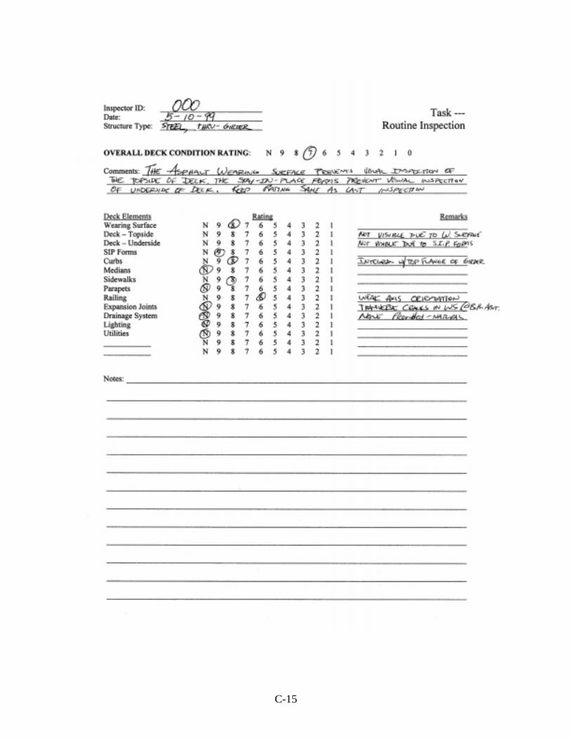
DEFECT AND CONDITION SUMMARY FOR VAN BUREN ROAD BRIDGE
DECK: Wearing Surface: No wearing surface is provided. Rating Deck Top Surface: The deck surface is tined to a depth of approximately 1/8
in. Hairline, transverse cracks were noted to extend across nearly the full deck width. Although difficult to identify due to the tined surface, it is believed that 10 to 15 hairline transverse cracks exist. The deck appears to be in good condition; however, a chain drag survey identified delaminations over approximately 15 to 20 percent of the deck surface. The majority of the delaminations occurred in Spans 1 and 2.
Rating
Deck Underside: The deck soffit was generally in fair to good condition. A
number of transverse cracks were observed, with a limited number exhibiting efflorescence. Transverse cracks were generally more prevalent in the deck cantilevers. Several small spalls (<0.56 m2) and exposed reinforcement due to inadequate cover were identified.
Rating
Parapet: The parapets are built integrally with the deck. The
parapets were in good condition, with typical shrinkage cracks observed. Several exhibited light efflorescence. Several small spalls at the shallow reinforcement were observed.
Rating
Railings: The railings were in good condition. No deterioration was
noted. Rating
Joints: The joint material is generally missing.
Rating
N
1
7
7
7
6
D-28
Drainage: Drains were functioning properly. Drain run-off has stained concrete surfaces on the deck facia.
Rating
Overall: The deck appears to be in good condition. Transverse cracking, although present, does not appear to be supporting through-deck leakage. Delaminations are not visibly identifiable, and therefore are not included in the rating determination. A “5” would be assigned should results of a sounding survey be considered.
Rating
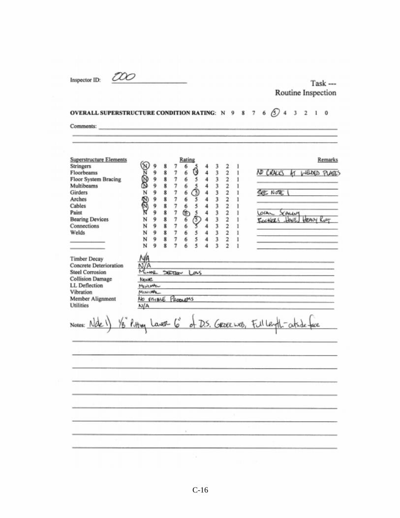
SUPERSTRUCTURE: Bearings: The bearings showed limited surface corrosion, with some
accumulated debris typically around the bearing base plate. Bearings were recently painted. Expansion bearings in Span 1 do not appear to be functioning, while expansion bearings in Spans 2 and 3 exhibit scrape marks due to movement of the superstructure. The bearing masonry plate for two bearings in Span 2 is partially unsupported.
Rating
Joints: None. The superstructure consists of three simple spans. Rating
Diaphragms: In general, the diaphragms were in good condition. Rating
Overall: The primary and secondary framing was generally in good condition, with satisfactory paint condition. The bridge was spot-painted in late 1997. The spot paint was thick and inhibited detection of corrosion pitting, if present. No paint was removed during the inspection.
Crack-like indications at seven (three locations are within
Span 2) bottom flange cover plate weld terminations were noted. Several crack-like indications (none in Span 2) were noted in the paint at weld terminations of the vertical diaphragm stiffener-to-girder web connection. In general, this weld toe was of poor quality. These locations are
7
7
7
N
8
D-29
historically known to exhibit fatigue-cracking problems. A small area of the bottom flange in Span 2 was distorted, due to some previous impact.
NOTE: Further investigation would be required to discern
whether crack-like indications in the paint indicated fatigue cracks in the weld metal or parent material. This work was not done to preserve the integrity of the defect for further study by the NDEVC.
Rating SUBSTRUCTURE:
Wingwalls: The wingwalls were in good condition. Rating
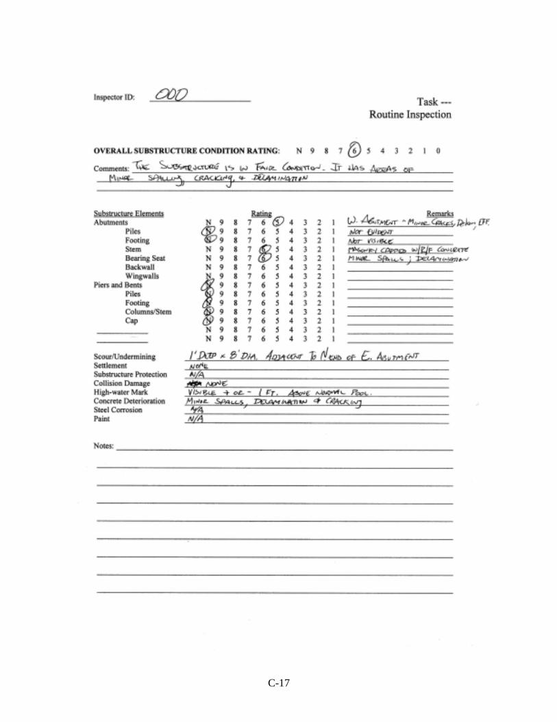
Abutments: Water staining and debris build-up on horizontal surfaces
characterized the condition of the abutments. Limited, minor cracking was observed.
Rating
Piers: The piers were in good condition. All piers exhibit water
staining due to the failed joints above. Pier 1, located in the stream bed, has experienced erosion of surface paste. A small area near the top of Pier 1 shows poor consolidation and moderate freeze/thaw damage. Several small spalls and exposed reinforcement were noted on the piers, but each was less than 0.093 m2 in area.
Rating
Slope Protection: The slope protection at the north abutment has settled
approximately 50 mm at the abutment. The lower 50 percent of the slope protection has experienced greater settlement and failure due to water action.
Rating
Overall: The abutments and piers were generally in very good condition. Some water staining, surface erosion, and limited cracking/delamination were observed.
Rating
8
8
7
8
5
7