Embed Size (px)
Citation preview
APPENDIX B – ATTACHMENT 1:
CARBON CAPTURE AND SEQUESTRATION PROTOCOL UNDER
THE LOW CARBON FUEL STANDARD

This Page Left Intentionally Blank

Carbon Capture and Sequestration Protocol under the Low Carbon Fuel Standard
March 6, 2018

This Page Left Intentionally Blank

TABLE OF CONTENTS
A. DEFINITIONS AND APPLICABILITY ................................................................... 9
1. Purpose ................................................................................................................ 9
2. Applicability........................................................................................................... 9
3. Definitions and Acronyms ..................................................................................... 9
B. ACCOUNTING REQUIREMENTS FOR CCS PROJECTS UNDER THE LCFS. 25
1. System Boundary ............................................................................................... 25
2. Quantification of Geologic Sequestration CO2 Emission Reductions ................. 28
2.1. Covered Greenhouse Gas Emissions for the LCFS...................................... 28
2.2. Greenhouse Emissions Reductions Calculation ........................................... 28
3. Invalidation and Buffer Account .......................................................................... 33
C. PERMANENCE REQUIREMENTS FOR GEOLOGIC SEQUESTRATION ........ 35
1. Permanence Certification of Geologic Carbon Sequestration Projects ............... 35
1.1. Application and Certification ......................................................................... 35
1.1.1. Third Party Review .................................................................................... 36
1.1.2. Certification Application Materials .............................................................. 36
1.1.3. Reporting ................................................................................................... 38
1.1.4. Recordkeeping .......................................................................................... 42
1.2. Terms and Conditions ................................................................................... 43
2. Site Characterization .......................................................................................... 43
2.1. Minimum Site Selection Criteria .................................................................... 43
2.2. Risk Assessment .......................................................................................... 44
2.3. Geologic and Hydrologic Evaluation Requirements ...................................... 45
2.3.1. Formation Testing and Well Logging Program .......................................... 51
2.4. Area of Review Delineation and Corrective Action ........................................ 55
2.4.1. Computational Modeling Requirements ..................................................... 57
2.4.2. AOR Delineation using Computational Modeling Results .......................... 60
2.4.3. Corrective Action Requirements ................................................................ 61
2.4.4. AOR Reevaluation ..................................................................................... 66
2.5. Baseline Monitoring ...................................................................................... 69
3. Well Construction and Operating Requirements................................................. 71
3.1. Well Construction .......................................................................................... 71

3.2. Pre-Injection Testing ..................................................................................... 74
3.3. Injection Well Operating Requirements ......................................................... 76
3.4. Operating Restrictions and Incident Response ............................................. 77
4. Injection Monitoring Requirements ..................................................................... 78
4.1. Testing and Monitoring ................................................................................. 78
4.2. Mechanical Integrity Testing ......................................................................... 81
4.2.1. Reporting of Mechanical Integrity Tests .................................................... 83
4.2.2. Loss of Mechanical Integrity ...................................................................... 83
4.3. CCS Project Monitoring ................................................................................ 84
4.3.1. CCS Project Emissions Monitoring ............................................................ 85
4.3.2. Monitoring, Measurement, and Verification of Containment ...................... 92
5. Well Plugging and Abandonment and Post-Injection Site Care and Site Closure 98
5.1. Well Plugging and Abandonment .................................................................. 98
5.2. Post-Injection Site Care and Site Closure ................................................... 100
6. Emergency and Remedial Response ............................................................... 104
6.1. Emergency and Remedial Response Requirements .................................. 105
7. Financial Responsibility .................................................................................... 108
8. Modification or Revocation and Reissuance of Permanence Certification ........ 114
8.1. Termination of Permanence Certifications .................................................. 115
8.2. Minor Modification of Permanence Certifications ........................................ 116
9. Legal Understanding, Contracts, and Post-Closure Care ................................. 116
Appendix A. Fugitive and Vented GHG Emissions: Injection into Depleted Oil and Gas and Saline Formations ............................................................... 121
Appendix B. CO2 Venting and Fugitive Emissions from CO2-EOR Operations .... 125
Appendix C. Converting Volume of CO2 to Mass .................................................. 131
Appendix D. Data Measurement/Generation and Reporting for Energy and Chemical Inputs ................................................................................................ 135
Appendix E. Emission Factors and Component Counts ........................................ 139
Appendix F. Emissions from CO2 Entrained in Produced Oil and Gas .................. 147
Appendix G. Determination of a CCS Project’s Risk Rating for Determining its Contribution to the LCFS Buffer Account .......................................... 151

FIGURES Figure 1. An example of geologic sequestration project indicating SSRs...................... 25 Figure 2. System boundary for CO2 capture and sequestration in oil and gas reservoirs used for CO2-EOR. ....................................................................................................... 26 Figure 3. System boundary for CO2 capture and sequestration in depleted oil and gas reservoirs and saline formations. .................................................................................. 27 Figure 4. Application process flow diagram. .................................................................. 35 Figure 5. Flow chart of monitoring and modeling for a CCS project design. .................. 56 Figure 6. Well evaluation flow chart............................................................................... 63

TABLES Table 1. Quarterly and Annual Reporting Calendar ...................................................... 39 Table 2. Risk classification and response ..................................................................... 45 Table 3. Degrees of risk for emergency events ........................................................... 105

ATTACHMENT 1: CCS Protocol – A: Definitions and Applicability Page 9/175
CARBON CAPTURE AND SEQUESTRATION PROTOCOL UNDER THE LCFS A. DEFINITIONS AND APPLICABILITY 1. Purpose The California Air Resources Board’s (CARB’s) Carbon Capture and Sequestration (CCS) Protocol includes two parts: Accounting Requirements and Permanence Requirements. The purpose of the Accounting and Permanence Requirements are to establish a methodology to determine if a CCS project will result in the permanent sequestration of carbon dioxide (CO2) and, if so, to calculate the greenhouse gas (GHG) benefits under the Low Carbon Fuel Standard (LCFS). The CCS Protocol is designed to meet the requirements in Assembly Bill 32∗ that GHG emissions reductions achieved from voluntary action, such as CCS projects, must be real, permanent, additional, quantifiable, verifiable, and enforceable. The Accounting Requirements outline the methodology for estimating emissions associated with CCS projects, including emissions from CCS operations, CO2 surface leakage, above ground fugitive emissions, and post-well closure emissions. Applicants must use the Accounting Requirements to calculate credits or carbon intensity reductions for CCS projects under the LCFS. The Permanence Requirements establish criteria for the permanent geologic sequestration of CO2 for CCS projects to qualify for GHG reductions under CARB’s existing climate programs in compliance with AB 32. The Permanence Requirements set forth criteria and standards that CCS projects must implement in order to acquire Permanence Certification. 2. Applicability The CCS Protocol applies to CCS projects that capture CO2 and sequester it onshore, in either saline or depleted oil and gas reservoirs, or oil and gas reservoirs used for CO2-EOR. The CCS Protocol applies to both existing and new CCS projects and CCS CO2 injection wells if the project and associated wells can meet the requirements for permanence pursuant to section C of this protocol. 3. Definitions and Acronyms (a) Definitions: For purposes of this document, the definitions in title 13, California
Code of Regulations, section 95481 apply, except as otherwise specified in the document. The following definitions also apply to this document:
∗ Assembly Bill 32, the Global Warming Solutions Act of 2006, AB 32, Statutes of 2006, Chapter 488.

ATTACHMENT 1: CCS Protocol – A: Definitions and Applicability Page 10/175
(1) “Active life” or “operational life” means the operational phase of a CCS project in which injection and, if applicable, production occurs. The term omits the monitoring and site care phase of the CCS project following injection completion.
(2) “Area of review” means the area encompassing the lateral extent of the pressure front at depth and the surface footprint of the storage complex.
(3) “Aqueous diffusion coefficient” is the magnitude of the molar flux through a surface per unit concentration gradient. Typical diffusion coefficients for organic compounds in aqueous solution range between 10-10 to 10-9 m2/s.
(4) “Artificial penetration” means any man-made structures, such as wells or mines, which provide a flow path out of the sequestration zone or storage complex.
(5) “Assets” means all existing and all probable future economic benefits obtained or controlled by a particular entity.
(6) “Biogenic CO2” refers to CO2 produced from biomass.
(7) “Borehole” means a cylindrical hole cut into rock or soil by drilling. Also refers to the inside diameter of the wellbore wall (i.e., the rock face that bounds the drilled hole).
(8) “Bottom-hole pressure” means the pressure at the bottom of the wellbore within the sequestration zone. It may be measured directly with a downhole pressure transducer, or in some cases estimated from the surface pressure and the height and density of the fluid column.
(9) “Brine” is water containing dissolved minerals and inorganic salts in solution, including sodium, calcium, or bromides. Water containing dissolved solids in excess of 100 g/L is classified as brine. Large quantities of brine are often produced along with oil and gas.
(10) “Brittleness” is a property of a rock in which failure under a load occurs by fracturing, rather than by plastic deformation.
(11) “Capillary pressure” means the pressure difference across the interface of two immiscible fluids (e.g., CO2 and water).
(12) “Capillary entry-pressure” means the pressure that a non-wetting fluid (e.g. CO2) must overcome to displace water held tightly by capillary forces in the pores of a rock or sediment.

ATTACHMENT 1: CCS Protocol – A: Definitions and Applicability Page 11/175
(13) “Capture Facility Operator” means the operator responsible for the CCS capture facility.
(14) “Carbon capture and sequestration (CCS)” means the process of concentrating CO2 present in flue and/or exhaust gases, or air, via chemical and/or physical separation methods, transporting the CO2 to an injection site, and injecting and permanently sequestering the captured CO2.
(15) “Carbon dioxide equivalent” or “CO2 equivalent” or “CO2e” means the number of metric tons of CO2 emissions with the same global warming potential as one metric ton of another greenhouse gas. For the purposes of the LCFS CCS Protocol, global warming potential values listed in the CA-GREET model are used to determine the CO2 equivalent of GHG emissions.
(16) “Carbon intensity” has the same meaning as in 13, CCR, section 95481.
(17) “Casing” or “casing string” means a pipe or tubing of appropriate material (typically made of steel as used in oil and gas wells), of varying diameter and weight, lowered into a borehole during or after drilling in order to support the sides of the hole and thus prevent the walls from caving, to prevent the loss of drilling mud into porous ground, to prevent water, gas, or other fluid from entering or leaving the hole, or to allow conveyance of fluids to/from the surface from/to a specific location in the subsurface. “Long string casing” refers to the last, or longest, casing set in a well, set through the sequestration or production reservoir. “Surface casing” refers to the first string of casing that is set in a well, and varies in length from a few hundred to a few thousand feet.
(18) “Casing inspection logs (CIL)” are used to determine the presence or absence of corrosion in the long-string casing.
(19) “Casing shoe” means the bottom of the casing string or the equipment run at the bottom of the casing string.
(20) “CCS capture facility” means any plant, building, structure, or stationary equipment that captures CO2 generated from industrial processes, or the atmosphere.
(21) “CCS project” means the overall CCS project operations, including those of the CCS capture facility and geologic sequestration site and activities.
(22) “CCS Project Operator” means the operator responsible for the CCS project.
(23) “CO2-enhanced oil recovery (CO2-EOR)” means the injection into and storage of CO2 in oil reservoirs contributing to the extraction of crude oil.

ATTACHMENT 1: CCS Protocol – A: Definitions and Applicability Page 12/175
(24) “CO2 injection” means the process of injecting CO2 into geologic reservoirs.
(25) “CO2 leakage” means any movement of stored CO2 out of the intended sequestration zone and above the storage complex. “Atmospheric leakage” means the intended or unintended release of stored CO2 outside the storage complex to the surface and atmosphere. “Subsurface leakage” means the vertical movement of stored CO2 out of the storage complex and/or AOR that does not reach the atmosphere.
(26) “CO2 plume” means the physical extent underground, in three dimensions, of the free-phase and dissolved CO2 stream.
(27) “CO2 stream” means CO2 that has been captured from an emission source (e.g., a power plant), plus incidental associated substances derived from the source materials and the capture process, and any substances added to the stream to enable or improve the injection process.
(28) “CO2 recycling” means the process that separates CO2 from produced oil, water, and natural gases for re-injection in the subsurface or transfer off site.
(29) “Computational model” means a mathematical representation of the injection project and relevant features, including injection wells, site geology, and fluids present. For a CCS project, site-specific geological information is used as an input to a computational code, creating a computational model that provides predictions of subsurface conditions, fluid flow, and CO2 plume and pressure front movement at that site. The computational model includes all model input and predictions (i.e., outputs).
(30) “Confining pressure” means the combined hydrostatic and lithostatic stresses, or the total weight of the interstitial pore water and rock above a specified depth.
(31) “Confining layer” means a laterally extensive geologic formation, group of formations, or part of a formation, stratigraphically overlying the sequestration zone that exhibits low permeability and/or high capillary entry-pressure (e.g. a clay-rich shale or mudstone) such that it impedes the upward migration of fluid(s). The “primary confining layer” refers to the confining layer directly above the sequestration zone. “Secondary confining layer” refers to a confining layer directly above a dissipation zone and above the storage complex.
(32) “Constitutive relationships” represent empirically based approximations used to simplify the real-world system and estimate unknowns. Examples include saturation-relative permeability relationships, interphase mass transfer relations, and solution reaction relations.
ATTACHMENT 1: CCS Protocol – A: Definitions and Applicability Page 13/175
(33) “Corporate parent” means a corporation that directly owns at least 50 percent of the voting stock of the corporation that is the CCS Project Operator; the latter corporation is deemed a subsidiary of the parent corporation.
(34) “Corrective action” means the use of California Air Resources Board-approved methods to ensure that any artificial penetrations within an AOR do not serve as conduits for the movement of fluids out of the intended storage complex.
(35) “Corrosion” means the loss of metal due to chemical or electrochemical reactions that may cause loss of mass or thickness, cracking, or pitting of well components (casing, tubing, or packer).
(36) “Corrosion coupons” are small, pre-weighed, and measured pieces of metal made of the construction materials that are exposed to well fluids for a defined period, then removed, cleaned, and weighed to determine the corrosion rate. The coupon is made from the same material as the well’s casing or tubing. The average corrosion rate in the well is calculated from the weight loss of the coupon.
(37) “Corrosion loops” are sections of tubing that are valved so that some of the injection stream is passed through a small pipe running parallel to the injection pipe at the surface of the well. These loops allow for monitoring and analysis of corrosion.
(38) “Current assets” means cash or other assets or resources commonly identified as those that are reasonably expected to be realized in cash, sold, or consumed during the normal operating cycle of the business.
(39) “Current liabilities” means the obligations whose liquidation is reasonably expected to require the use of existing resources properly classifiable as current assets or the creation of other current liabilities.
(40) “Darcy’s law” is an equation that defines the ability of a fluid to flow through a porous medium such as rock. It relies on the fact that the amount of flow between two points is directly related to the difference in pressure between the points, the distance between the points, and the interconnectivity of flow pathways in the rock between the points.
(41) “Depleted oil and gas reservoirs” means reservoirs that do not currently produce oil or gas, and are considered to have no economically recoverable oil or gas with current technology.
(42) “Depositional environment” is a specific type of place on the surface of the earth in which certain chemical, biological, and physical characteristics affect

ATTACHMENT 1: CCS Protocol – A: Definitions and Applicability Page 14/175
the deposition of sediments. The three overarching types of depositional environment include continental, marginal marine, and deep marine.
(43) “Deviated well” means a well that is not drilled vertically for its whole length, or a well with an inclination designed to be other than zero degrees from vertical.
(44) “Dissipation interval” is a stratigraphic interval with hydrogeologic properties sufficient to attenuate pressure created by CO2 or formation fluid migration along an unidentified leakage pathway through the confining layer.
(45) “Downhole measurements” are measurements collected from within the wellbore or borehole, either while drilling or during well maintenance or operation. Downhole measurements are used to determine physical, chemical, and structural properties of formations penetrated by a drill hole. Using a variety of instruments, these measurements are collected to make continuous in-situ records as a function of depth.
(46) “Ductility” means the property of a rock by which the rock plastically deforms under a load, rather than breaking by fracturing.
(47) “Embodied GHG” means lifecycle greenhouse gas emissions associated with production and transport of process fuels and chemicals to the point of use (e.g., GHG from the production and transport of natural gas as process fuel to a refinery).
(48) “Entrained CO2” means CO2 that remains in water, oil, or natural gas after the (oil, water, and natural gas) separation has taken place.
(49) “Equation of state” refers to an equation that expresses the equilibrium phase relationship between pressure, volume, and temperature for a particular chemical species.
(50) “Fluid” means liquid or gas.
(51) “Fluid pressure” means the measure of the potential energy per volume of fluid, based on force acting per unit area (psi or kPa).
(52) “Formation compressibility” is the relative volume change of a formation per unit pressure change.
(53) “Fracture pressure” or “parting pressure” is the pressure in the wellbore above which the injection of fluids will cause the rock formation to fracture hydraulically.

ATTACHMENT 1: CCS Protocol – A: Definitions and Applicability Page 15/175
(54) “Fracture gradient” is the factor used to determine formation-fracturing pressure as a function of well depth in units of psi/ft.
(55) “Free-phase CO2 plume” means the portion of CO2 in supercritical, gaseous, or liquid phase, rather than as a dissolved component in native fluid (e.g., dissolved in brine), that occupies pore space within the sequestration zone.
(56) “Freshwater aquifer” means an aquifer that contains fewer than 10,000 mg/L total dissolved solids per the U.S. EPA Safe Drinking Water Act1.
(57) “Fugitive emissions” means unintentional leakage of greenhouse gases from such as connectors, block valves, control valves, pressure relief valves, orifice meters, and regulators.
(58) “Geographic location” means the location of a well or monitoring site as referenced to a geographic coordinate system (e.g. latitude and longitude) using a global positioning system.
(59) “Geologic carbon sequestration (GCS)” means the permanent (≥ 100 years) containment of CO2 within deep subsurface rock formations. This term does not include the capture or transport of CO2.
(60) “Geologic formation” means a body of rock characterized by a degree of lithologic homogeneity that is prevailingly, but not necessarily, tabular and is mappable on the earth’s surface or traceable in the subsurface.
(61) “Geomechanical analysis” means to study rock mechanical characteristics and properties, such as fault and reservoir rock stability and confining layer integrity.
(62) “GHG emissions reductions” means the amount of greenhouse gas emissions (MT CO2) avoided by limiting the carbon intensity of fuels under LCFS.
(63) “Governing equation” means the mathematical formulae that form the basis of a computational code. For computational modeling, they govern the predicted behavior of fluids in the subsurface provided by the code. Governing equations are mathematical approximations for describing flow and transport of fluids and their components in the environment.
(64) “Hydraulic conductivity” is a measure of a material's capacity to transmit a fluid. It is defined as a constant of proportionality relating the specific medium under a unit hydraulic gradient.
(65) “Hydraulic head” is the force per unit area exerted by a column of liquid at a height above a depth and pressure of interest. If connected by permeable
1 U.S. EPA Underground Injection Control Program, 40 C.F.R. §144 (2014).

ATTACHMENT 1: CCS Protocol – A: Definitions and Applicability Page 16/175
flow paths, fluids flow down a hydraulic gradient, from points of higher hydraulic head to points of lower hydraulic head.
(66) “Injectivity” means the pressure differential over existing reservoir pressure required to inject a unit volume of fluid in a given unit of time. It is typically expressed as psi/bbl/day (psi per barrel per day), but can be expressed in any combination of pressure, volume, and time units.
(67) “Isopach map” means a contour map showing equal values of true stratigraphic thickness of a formation.
(68) “Leak-off test” is a test to determine the strength or fracture pressure of the formation, usually conducted immediately after drilling below a new casing shoe. The results of the leak-off test dictate the maximum pressure or mud weight that may be applied to the well during drilling operations. To maintain a small safety factor to permit safe well control operations, the maximum operating pressure is usually slightly below the leak-off test result.
(69) “Liner” means a casing string that does not extend to the top of the wellbore (i.e., the ground surface), but instead is anchored or suspended from inside the bottom of the previous casing string. The liner can be fitted with special components so that it can be connected to the surface at a later time, if need be.
(70) “Lithofacies” means a mappable subdivision of a rock unit with distinctive and characteristic lithologic features.
(71) “Lithology” means the general description and classification of a rock or rock sequence in terms of their color, texture, and composition.
(72) “Lithostatic stress” means component of confining pressure derived from the weight of the column of rock above a specified level.
(73) “Mechanical integrity” means that all well barrier envelopes, including but not limited to, the tubing, packer, wellhead, and casing, reliably perform their primary functions of containing pressure and are free from leakage.
(74) “Mechanical integrity test” means a test that consists of two parts conducted on a well to ensure that there are no leaks and that the mechanical components of the well function in a way that is protective of public health and the environment. The injection well has two parts: internal and external. The internal part has mechanical integrity if no leakage is noted in the packer, casing, or tubing. The external part has mechanical integrity if no movement of fluid is noted through the vertical channels that are adjacent to the well.

ATTACHMENT 1: CCS Protocol – A: Definitions and Applicability Page 17/175
(75) “Microannuli” means small gaps that may form between the casing or liner and the surrounding cement sheath within a well. Microannuli most commonly form due to temperature and/or pressure fluctuations during or after the cementing process. Such fluctuations cause small movement of the steel casing, breaking the cement bond and creating a microannulus. If it is severe and connected, a microannulus can jeopardize the hydraulic efficiency of a primary cementing operation, allowing communication between formations and the possibility of fluid migration out of storage complex.
(76) “Model domain” means the lateral extent of the model in all directions.
(77) “Model parameter” means a variable in the governing equations of a computational model that may vary throughout the domain, or may vary in space and time. Various system aspects are sometimes lumped together in simulation models and described by effective parameters that are estimated or averaged. Parameters describe properties of the fluids present, porous media, and fluid sources and sinks (e.g., injection well). Examples of model parameters include intrinsic permeability, fluid viscosity, and fluid injection rate.
(78) “Multiphase flow” means the flow of two immiscible phases. For the purposes of the CCS Protocol, the pertinent phases are CO2 (as a gas, liquid, or supercritical fluid), and brine or oil.
(79) “Net worth” means total assets minus total liabilities and is equivalent to owner’s equity.
(80) “Net working capitol” means current assets minus current liabilities.
(81) “Permanent sequestration” or “permanence” means sequestered CO2 will remain within the storage complex for at least 100 years.
(82) “Perforation interval” means the section of wellbore that has been prepared for production by creating channels between the reservoir formation and the wellbore.
(83) “Permeability” means the measure of a rock’s ability to transmit fluids.
(84) “Petrophysical analysis” means the study of the fundamental chemical and physical properties of reservoir rocks and their contained fluids. The term, “petrophysics,” encompasses multiple types of rock studies, including core analysis, sample descriptions, petrography, scanning electron microscopy, well log analysis, and other forms of detailed laboratory data.
(85) “Pore pressure” means the pressure of a fluid held within spaces between particles (i.e. pore space) in a rock.

ATTACHMENT 1: CCS Protocol – A: Definitions and Applicability Page 18/175
(86) “Pore space” means the volume of rock or soil voids that can be filled by a
fluid, such as water, air, or CO2.
(87) “Porosity” means the relative volume percentage of the void space in the rock that is not occupied by solid grains or minerals. The space between crystals or grains in a rock that is available to be filled with a fluid such as water, oil, or gas, is called the “pore space.”
(88) “Post-injection site care” means appropriate monitoring and other actions (including corrective action) needed following the completion of injection to ensure permanence of sequestered CO2.
(89) “Precipitation kinetics” means the rates of mineral precipitation from a solution. Mineralization reactions are very sensitive to kinetic rate parameters.
(90) “Pressure front” means the region surrounding CO2 injection wells in which the pressure rise is sufficient to lift formation fluids from the sequestration zone, above the storage complex.
(91) “Pressure fall-off test” means a field test conducted by ceasing injection for a period (i.e., shutting-in the well) and monitoring pressure decay at the well. The pressure change is analyzed using pressure transient analysis, a technique based on the mathematical relationships between flow rate, pressure, and time. The information from these analyses helps determine injection potential. It can also derive permeability, reservoir boundary shape, and reservoir pressures.
(92) “Project GHG emissions” means the GHG emissions from various activities associated with a CCS project.
(93) “Pump test” means a field experiment in which a well is pumped at a controlled rate and water-level response (drawdown) is measured in one or more surrounding observation wells and optionally in the pumped well itself. Response data from pumping tests are used to estimate the hydraulic properties of aquifers, evaluate well performance, and identify aquifer boundaries.
(94) “Reactive transport model” means a model of the chemical reactions between constituents (e.g., injected CO2, formation fluids, and the reservoir rock). These models incorporate rate-limited intra-aqueous reactions, mineral dissolution and precipitation, changes in porosity and permeability due to these reactions, and multi-component gas mixtures to model and predict the impact of CO2 and its co-injectates (e.g., hydrogen sulfide, sulfur dioxide) on aquifer acidification, the concomitant mobilization of metals, and any mineral

ATTACHMENT 1: CCS Protocol – A: Definitions and Applicability Page 19/175
trapping of CO2. These models can also be used to assess corrosion of well construction materials.
(95) “Recycled CO2” means CO2 that is separated from oil, water, and natural gases, and reinjected back into the reservoir.
(96) “Relative permeability” means the ratio of the effective permeability of a particular fluid at a particular saturation to the absolute permeability of that fluid at total saturation (dimensionless). If a single fluid is present in a rock, its relative permeability is 1.0.
(97) “Rock compressibility” means the relative volume change of matter per unit pressure change under conditions of constant temperature. Rock compressibilities are typically displayed in psi-1.
(98) “Sequestration and storage site” means the surface site and corresponding infrastructure where CO2 injection occurs, and includes the storage complex at depth, where CO2 is stored.
(99) “Site closure” means the point or date, after at least 100 years and as determined by the Executive Officer following the requirements under subsection C.5.2, at which point the CCS Project Operator is released from post-injection site care responsibilities.
(100) “Sequestration zone” means the reservoir into which CO2 is injected for geologic sequestration.
(101) “Skin factor” means a dimensionless pressure drop caused by a flow restriction in the near-wellbore region, typically associated with damage during drilling and well operations.
(102) “Specific storage” means the volume of water released from storage from a unit volume of aquifer per unit decline in hydraulic head (displayed in L-1).
(103) “Step rate test” means test in which a fluid is injected for a defined period in a series of increasing pump rates. The resulting data are used to determine the maximum safe injection rate possible without fracturing the reservoir rock.
(104) “Stratigraphic test well” means a hole drilled for the sole purpose of gaining structural or stratigraphic information to aid in subsurface exploration.
(105) “Storage coefficient” means the volume of water released from storage by a confined aquifer per unit surface area of aquifer per unit decline in hydraulic head normal to the surface and equal to the product of specific storage and the saturated thickness (dimensionless).
ATTACHMENT 1: CCS Protocol – A: Definitions and Applicability Page 20/175
(106) “Storage complex” means the three-dimensional subsurface volume that is characterized, modified by corrective actions, and monitored so that the CCS Project is able to meet the requirements for carbon sequestration under the Permanence Requirements (section C).
(A) For saline and depleted oil and gas reservoirs, the storage complex includes the injection zone (in which the CO2 is emplaced), a sequestration volume, which is expected to contain the CO2, and overlying and possibly underlying geologic formations that are required to provide assurance of storage. The storage complex must include a confining system that retards vertical migration of CO2 (confining layer or primary confining layer). The storage complex must also include at least one overlying dissipation zone (dissipation interval) and at least one additional confining layer (secondary confining layer) to increase storage security and reduce other risks. The storage complex must extend laterally over 1) the volume from which CO2 (as a free or dissolved phase) could escape from storage in the subsurface if a permeable pathway exists, and 2) the associated pressure front.
(B) For CCS projects utilizing CO2 injection for EOR purposes, the storage complex is the three-dimensional extent of the reservoir used for oil production and CO2 storage. The storage complex for a CO2-EOR CCS project is delineated by the geologic extent of the reservoir such as impervious rock, structural closure, decrease or loss of porosity and permeability, or hydrodynamic forces in a three dimensional image.
(107) “Stratigraphy” means the classification of sedimentary rocks based on their lithologic properties and geometric relations, such as spatial distribution, depositional environment, composition, and age.
(108) “Supercritical CO2” means the physical state where CO2 exhibits properties of both a gas and a liquid when its temperature and pressure exceeds the critical temperature (87.98 °F) and pressure (1,071 psi).
(109) “System boundary” means a delineation of activities/processes that are considered part of the project when analyzing emissions from CCS projects.
(110) “Tangible net worth” means the tangible assets that remain after deducting liabilities; such assets would not include intangibles such as goodwill and rights to patents or royalties.
(111) “Total dissolved solids (TDS)” means milligrams per liter of total dissolved solids content. Solids content includes inorganic salts (principally calcium, magnesium, potassium, sodium, bicarbonates, chlorides, and sulfates) and some small amounts of organic matter that are dissolved in water.
ATTACHMENT 1: CCS Protocol – A: Definitions and Applicability Page 21/175
(112) “Transmissibility” means a measure of the conductivity of the formation corrected for the viscosity of the flowing fluid. It is a coefficient associated with Darcy’s law, which characterizes flow through porous media. It is equal to the coefficient of permeability (hydraulic conductivity) multiplied by the thickness of the formation.
(113) “Transmissive fault or fracture” means a fault or fracture that has sufficient permeability and vertical extent to allow fluids to move laterally or vertically along the fault or fracture, or within an associated damaged zone.
(114) “True stratigraphic thickness” means the thickness of rock layer after correcting for the dip (inclination) of the layer and the deviation of the well that penetrates it. Values of true stratigraphic thickness in an area can be plotted to create an isopach map.
(115) “True vertical depth” means the vertical distance from a point in the well (usually the current or final depth) to a point at the surface. If the well is deviated, the measurement may be different from the “measured depth.”
(116) “True vertical thickness” means the thickness of a layer of rock measured
vertically from a reference point at the surface. Values of true vertical thickness in an area can be plotted to create an isopach map.
(117) “Tubing” or “production tubing” means any tubing used to inject or produce fluids, respectively.
(118) “Unconfined compressive stress” is a measure of a material’s strength. The unconfined compressive strength (UCS) is the maximum axial compressive stress that a right-cylindrical sample of material can withstand under unconfined conditions. It is also known as the “uniaxial compressive strength” of a material because the application of compressive stress is only along one axis-the longitudinal axis-of the sample.
(119) “Vadose zone” means the unsaturated zone of the subsurface above the groundwater table. The soil and rock within this zone typically contains air and water within its pore space.
(120) “Vented emissions” means intentional or designed releases of CH4 or CO2 including process designed flow to the atmosphere through seals or vent pipes, equipment blowdown for maintenance, and direct venting of gas used to power equipment (such as pneumatic devices).
(121) “Vertical stress” means the force per unit area imposed on a layer of rock. Vertical stress is the combined stress due to the total weight of rock and interstitial fluids above a specified depth.

ATTACHMENT 1: CCS Protocol – A: Definitions and Applicability Page 22/175
(122) “Viscosity” means the measure of a liquid’s resistance to flow.
(123) “Well” or “wellbore” means a hole that is drilled into the Earth’s subsurface. A wellbore can be encased by materials such as steel and cement, or it may be uncased.
(124) “Wireline” means a wire or cable that is used to deploy tools and instruments downhole and transmits data to the surface.
(125) “Workover” means the process of performing major maintenance or remedial treatments on an injection or production well. In many cases, workover implies the removal and replacement of the production tubing string after the well has been killed and a workover rig has been placed on location.
(b) Acronyms:
“API” means American Petroleum Institute. “AOR” means Area of Review. “APCD” means Air Pollution Control District. “AQMD” means Air Quality Management District. “ASTM” means ASTM International, formerly known as the American Society for
Testing and Materials. “CARB” means California Air Resources Board. “CA-GREET” means the Greenhouse gases, Regulated Emissions, and Energy
use in Transportation Model, as referred to in the LCFS regulation. “CERCLA” means Comprehensive Environmental Response, Compensation, and
Liability Act. “CAA” means Clean Air Act. “CWA” means Clean Water Act “CCS” means Carbon Capture and Sequestration. “CH4” means methane. “CIL” means casing inspection log. “CO” means carbon monoxide. “CO2” means carbon dioxide. “CO2e” means CO2 equivalent. “CO2(aq)” means carbon dioxide dissolved in an aqueous solution. “CO2(g)” means carbon dioxide as a free gas phase. “CO2-EOR” means CO2-enhanced oil recovery. “GCS” means geologic carbon sequestration. “DOGGR” means the California Division of Oil, Gas, and Geothermal Resources. “GHG” means greenhouse gas. “GPS” means global positioning system. “LCFS” means the Low Carbon Fuel Standard (title 17, California Code of
Regulations, section 95480 et seq.) “MRR” means the Regulation for the Mandatory Reporting of Greenhouse Gas
Emissions (title 17, California Code of Regulations, sections 95100 et seq.)
ATTACHMENT 1: CCS Protocol – A: Definitions and Applicability Page 23/175
“MT” means metric ton. “N2O” means nitrous oxide. “NESHAPS” means the National Emission Standards for Hazardous Pollutants
preconstruction approval under the Clean Air Act. “NPDES” means the National Pollution Discharge Elimination System under the
Clean Water Act. “PSD” means the Prevention of Significant Deterioration program under the
Clean Air Act. “PSI” means pounds per square inch. “RCRA” means the Resource Conservation and Recovery Act. “SDWA” means Safe Drinking Water Act. “SIC” means Standard Industrial Classification codes for classifying industries by
a four-digit code. “SSR” means sources, sinks, and reservoirs. “TDS” means total dissolved solids. “TOC” means total organic carbon. “US EPA UIC” or “UIC” means the United States Environmental Protection
Agency Underground Injection Control program.2 “VOC” means volatile organic compound.
2 EPA Underground Injection Control Program, 40 C.F.R. §144, §145, and §146 (2014).

This Page Left Intentionally Blank

ATTACHMENT 1: CCS Protocol – B: Accounting Page 25/175
B. ACCOUNTING REQUIREMENTS FOR CCS PROJECTS UNDER THE LCFS 1. System Boundary The Accounting Requirements for CCS delineate a system boundary that covers all CO2 sources, sinks, and reservoirs (SSRs) from a CCS project. All SSRs within the system boundary must be accounted for when quantifying emissions reductions from CO2 sequestration. Typically, SSRs included in the system boundary are carbon capture and compression, CO2 transport, and CO2 injection. Note that the injection and storage (or sequestration) site may be geographically separate from the capture site as shown in Figure 1.
Figure 1. An example of geologic sequestration project indicating SSRs.3
The specific types of equipment and sources covered by the system boundary can vary by CCS project types. Figure 2 shows the system boundary for capturing CO2 and sequestering it in oil and gas reservoirs used for CO2-EOR indicating which SSRs are included. Likewise, Figure 3 shows the system boundary for capturing CO2 and sequestering it in depleted oil and gas reservoirs and saline formations. In either case, the system boundary begins with carbon capture and ends with injection operations including CO2 leakage. Any emissions downstream of the sequestration site (except entrained CO2 in the case of CO2-EOR) are excluded since they are associated with the downstream products rather than the CCS project. For example, GHG emissions associated with crude oil transport from the CO2-EOR facility and subsequent refining are not accounted for within the project boundary.
3Source: Energy and Earth Resources, Department of State Development, Business and Innovation within the Victorian State Government (Australia) https://breakingenergy.com/2014/06/13/infographic-carbon-capture-and-storage-ccs/

ATTACHMENT 1: CCS Protocol – B: Accounting Page 26/175
Figure 2. System boundary for CO2 capture and sequestration in oil and gas reservoirs used for CO2-EOR.

ATTACHMENT 1: CCS Protocol – B: Accounting Page 27/175
Figure 3. System boundary for CO2 capture and sequestration in depleted oil and gas reservoirs and saline formations.

ATTACHMENT 1: CCS Protocol – B: Accounting Page 28/175
2. Quantification of Geologic Sequestration CO2 Emission Reductions This section describes the methodology for estimating GHG emissions reductions by sequestering CO2 in oil and gas or saline reservoirs. 2.1. Covered Greenhouse Gas Emissions for the LCFS Under the LCFS, GHG accounting relies on CA-GREET. In addition to CO2, CH4, and N2O, CA-GREET treats volatile organic compounds (VOC) and carbon monoxide (CO) as GHGs because they are eventually oxidized to CO2. In the context of CCS projects in the LCFS, emissions covered in this document under the LCFS are CO2, N2O, CH4, CO and VOC. The global warming potential values listed in the CA-GREET model are used to determine the CO2 equivalent of emissions. If N2O, CH4, CO and VOC present in the CO2 stream are sequestered during CO2 injection, they are not included in the quantification and will not be credited. 2.2. Greenhouse Emissions Reductions Calculation (a) Net annual GHG emissions reductions from CCS projects must be quantified
using Equation 1.
𝐺𝐺𝐺𝐺𝐺𝐺𝑟𝑟𝑟𝑟𝑟𝑟𝑟𝑟𝑟𝑟𝑟𝑟𝑟𝑟𝑟𝑟𝑟𝑟 = 𝐶𝐶𝐶𝐶2𝑖𝑖𝑖𝑖𝑖𝑖𝑖𝑖𝑖𝑖𝑖𝑖𝑖𝑖𝑖𝑖 − 𝐺𝐺𝐺𝐺𝐺𝐺𝑝𝑝𝑟𝑟𝑟𝑟𝑝𝑝𝑟𝑟𝑟𝑟𝑟𝑟 (1)
Where: 𝐺𝐺𝐺𝐺𝐺𝐺𝑟𝑟𝑟𝑟𝑟𝑟𝑟𝑟𝑟𝑟𝑟𝑟𝑟𝑟𝑟𝑟𝑟𝑟 = Net GHG reductions (MT CO2e/year). 𝐶𝐶𝐶𝐶2𝑖𝑖𝑖𝑖𝑖𝑖𝑖𝑖𝑖𝑖𝑖𝑖𝑖𝑖𝑖𝑖 = Amount of injected CO2 (MT CO2/year). Excludes recycled
CO2 in the case of CO2-EOR (equal to purchased CO2 per year measured at the point of injection).
𝐺𝐺𝐺𝐺𝐺𝐺𝑝𝑝𝑟𝑟𝑟𝑟𝑝𝑝𝑟𝑟𝑟𝑟𝑟𝑟 = Project GHG emissions (MT CO2e/year). If the injected CO2 consists of CO2 derived from various sources/facilities, a mass-balance approach must be used to assign the injected amount to the various sources of carbon capture based on metered data and contractual agreements between the CO2 supplier and CCS project operator. CO2 from natural underground CO2 reservoirs must be omitted from 𝐶𝐶𝐶𝐶2𝑖𝑖𝑖𝑖𝑖𝑖𝑖𝑖𝑖𝑖𝑖𝑖𝑖𝑖𝑖𝑖 in Equation 1.
(b) Annual project GHG emissions must be calculated using Equation 2. Each variable in Equation 2 must include both direct emissions as well as upstream (indirect) emissions associated with the corresponding specific activity, and must be determined pursuant to subsections B.2.2(c) through B.2.2(e) below.
𝐺𝐺𝐺𝐺𝐺𝐺𝑝𝑝𝑟𝑟𝑟𝑟𝑝𝑝𝑟𝑟𝑟𝑟𝑟𝑟 = 𝐺𝐺𝐺𝐺𝐺𝐺𝑟𝑟𝑐𝑐𝑝𝑝𝑟𝑟𝑟𝑟𝑟𝑟𝑟𝑟 + 𝐺𝐺𝐺𝐺𝐺𝐺𝑟𝑟𝑟𝑟𝑐𝑐𝑟𝑟𝑡𝑡𝑝𝑝𝑟𝑟𝑟𝑟𝑟𝑟 + 𝐺𝐺𝐺𝐺𝐺𝐺𝑟𝑟𝑟𝑟𝑝𝑝𝑟𝑟𝑟𝑟𝑟𝑟𝑟𝑟𝑟𝑟𝑟𝑟 + 𝐺𝐺𝐺𝐺𝐺𝐺𝑟𝑟𝑑𝑑𝑑𝑑𝑑𝑑 (2)
Where:
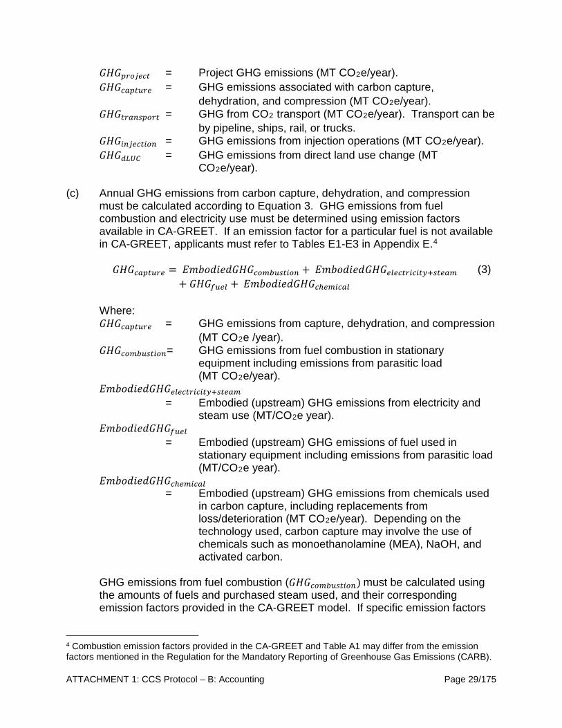
ATTACHMENT 1: CCS Protocol – B: Accounting Page 29/175
𝐺𝐺𝐺𝐺𝐺𝐺𝑝𝑝𝑟𝑟𝑟𝑟𝑝𝑝𝑟𝑟𝑟𝑟𝑟𝑟 = Project GHG emissions (MT CO2e/year). 𝐺𝐺𝐺𝐺𝐺𝐺𝑟𝑟𝑐𝑐𝑝𝑝𝑟𝑟𝑟𝑟𝑟𝑟𝑟𝑟 = GHG emissions associated with carbon capture,
dehydration, and compression (MT CO2e/year). 𝐺𝐺𝐺𝐺𝐺𝐺𝑟𝑟𝑟𝑟𝑐𝑐𝑟𝑟𝑡𝑡𝑝𝑝𝑟𝑟𝑟𝑟𝑟𝑟 = GHG from CO2 transport (MT CO2e/year). Transport can be
by pipeline, ships, rail, or trucks. 𝐺𝐺𝐺𝐺𝐺𝐺𝑟𝑟𝑟𝑟𝑝𝑝𝑟𝑟𝑟𝑟𝑟𝑟𝑟𝑟𝑟𝑟𝑟𝑟 = GHG emissions from injection operations (MT CO2e/year). 𝐺𝐺𝐺𝐺𝐺𝐺𝑟𝑟𝑑𝑑𝑑𝑑𝑑𝑑 = GHG emissions from direct land use change (MT
CO2e/year).
(c) Annual GHG emissions from carbon capture, dehydration, and compression must be calculated according to Equation 3. GHG emissions from fuel combustion and electricity use must be determined using emission factors available in CA-GREET. If an emission factor for a particular fuel is not available in CA-GREET, applicants must refer to Tables E1-E3 in Appendix E.4
𝐺𝐺𝐺𝐺𝐺𝐺𝑟𝑟𝑐𝑐𝑝𝑝𝑟𝑟𝑟𝑟𝑟𝑟𝑟𝑟 = 𝐸𝐸𝐸𝐸𝐸𝐸𝐸𝐸𝐸𝐸𝐸𝐸𝐸𝐸𝐸𝐸𝐺𝐺𝐺𝐺𝐺𝐺𝑟𝑟𝑟𝑟𝑐𝑐𝑐𝑐𝑟𝑟𝑡𝑡𝑟𝑟𝑟𝑟𝑟𝑟𝑟𝑟 + 𝐸𝐸𝐸𝐸𝐸𝐸𝐸𝐸𝐸𝐸𝐸𝐸𝐸𝐸𝐸𝐸𝐺𝐺𝐺𝐺𝐺𝐺𝑟𝑟𝑒𝑒𝑟𝑟𝑟𝑟𝑟𝑟𝑟𝑟𝑟𝑟𝑟𝑟𝑟𝑟𝑟𝑟𝑒𝑒+𝑡𝑡𝑟𝑟𝑟𝑟𝑐𝑐𝑐𝑐
+ 𝐺𝐺𝐺𝐺𝐺𝐺𝑓𝑓𝑟𝑟𝑟𝑟𝑒𝑒 + 𝐸𝐸𝐸𝐸𝐸𝐸𝐸𝐸𝐸𝐸𝐸𝐸𝐸𝐸𝐸𝐸𝐺𝐺𝐺𝐺𝐺𝐺𝑟𝑟ℎ𝑟𝑟𝑐𝑐𝑟𝑟𝑟𝑟𝑐𝑐𝑒𝑒 (3)
Where: 𝐺𝐺𝐺𝐺𝐺𝐺𝑟𝑟𝑐𝑐𝑝𝑝𝑟𝑟𝑟𝑟𝑟𝑟𝑟𝑟 = GHG emissions from capture, dehydration, and compression
(MT CO2e /year). 𝐺𝐺𝐺𝐺𝐺𝐺𝑟𝑟𝑟𝑟𝑐𝑐𝑐𝑐𝑟𝑟𝑡𝑡𝑟𝑟𝑟𝑟𝑟𝑟𝑟𝑟= GHG emissions from fuel combustion in stationary
equipment including emissions from parasitic load (MT CO2e/year).
𝐸𝐸𝐸𝐸𝐸𝐸𝐸𝐸𝐸𝐸𝐸𝐸𝐸𝐸𝐸𝐸𝐺𝐺𝐺𝐺𝐺𝐺𝑟𝑟𝑒𝑒𝑟𝑟𝑟𝑟𝑟𝑟𝑟𝑟𝑟𝑟𝑟𝑟𝑟𝑟𝑟𝑟𝑒𝑒+𝑡𝑡𝑟𝑟𝑟𝑟𝑐𝑐𝑐𝑐 = Embodied (upstream) GHG emissions from electricity and
steam use (MT/CO2e year). 𝐸𝐸𝐸𝐸𝐸𝐸𝐸𝐸𝐸𝐸𝐸𝐸𝐸𝐸𝐸𝐸𝐺𝐺𝐺𝐺𝐺𝐺𝑓𝑓𝑟𝑟𝑟𝑟𝑒𝑒
= Embodied (upstream) GHG emissions of fuel used in stationary equipment including emissions from parasitic load (MT/CO2e year).
𝐸𝐸𝐸𝐸𝐸𝐸𝐸𝐸𝐸𝐸𝐸𝐸𝐸𝐸𝐸𝐸𝐺𝐺𝐺𝐺𝐺𝐺𝑟𝑟ℎ𝑟𝑟𝑐𝑐𝑟𝑟𝑟𝑟𝑐𝑐𝑒𝑒 = Embodied (upstream) GHG emissions from chemicals used
in carbon capture, including replacements from loss/deterioration (MT CO2e/year). Depending on the technology used, carbon capture may involve the use of chemicals such as monoethanolamine (MEA), NaOH, and activated carbon.
GHG emissions from fuel combustion (𝐺𝐺𝐺𝐺𝐺𝐺𝑟𝑟𝑟𝑟𝑐𝑐𝑐𝑐𝑟𝑟𝑡𝑡𝑟𝑟𝑟𝑟𝑟𝑟𝑟𝑟) must be calculated using the amounts of fuels and purchased steam used, and their corresponding emission factors provided in the CA-GREET model. If specific emission factors
4 Combustion emission factors provided in the CA-GREET and Table A1 may differ from the emission factors mentioned in the Regulation for the Mandatory Reporting of Greenhouse Gas Emissions (CARB).

ATTACHMENT 1: CCS Protocol – B: Accounting Page 30/175
are not available in CA-GREET, refer to emission factors provided in Tables E1-E3. Embodied GHG emissions of electricity must be calculated using electricity emission factors in the CA-GREET model. Embodied GHG emissions of steam can be calculated based on the enthalpy of steam as well as the fuel source and efficiency of the boiler. Embodied GHG emissions of chemicals (𝐸𝐸𝐸𝐸𝐸𝐸𝐸𝐸𝐸𝐸𝐸𝐸𝐸𝐸𝐸𝐸𝐺𝐺𝐺𝐺𝐺𝐺𝑟𝑟ℎ𝑟𝑟𝑐𝑐𝑟𝑟𝑟𝑟𝑐𝑐𝑒𝑒) must be calculated using the CA-GREET model or an equivalent method if the chemical in question is not modelled in CA-GREET. Embodied (upstream) GHG emissions of fuel (𝐸𝐸𝐸𝐸𝐸𝐸𝐸𝐸𝐸𝐸𝐸𝐸𝐸𝐸𝐸𝐸𝐺𝐺𝐺𝐺𝐺𝐺𝑓𝑓𝑟𝑟𝑟𝑟𝑒𝑒) must be calculated using the CA-GREET model or an equivalent method if the fuel in question is not modelled in CA-GREET.
(d) Annual GHG emissions from CO2 transport must be calculated using Equation 4. 𝐶𝐶𝐶𝐶2𝑣𝑣𝑖𝑖𝑖𝑖𝑖𝑖 and 𝐶𝐶𝐶𝐶2𝑓𝑓𝑓𝑓𝑓𝑓𝑖𝑖𝑖𝑖𝑖𝑖𝑣𝑣𝑖𝑖 in Equation 4 are zero if the CO2 is of biogenic origin, such as from sugar fermentation, or derived from direct air capture.
𝐺𝐺𝐺𝐺𝐺𝐺𝑟𝑟𝑟𝑟𝑐𝑐𝑟𝑟𝑡𝑡𝑝𝑝𝑟𝑟𝑟𝑟𝑟𝑟 = 𝐺𝐺𝐺𝐺𝐺𝐺𝑟𝑟𝑟𝑟𝑐𝑐𝑐𝑐𝑟𝑟𝑡𝑡𝑟𝑟𝑟𝑟𝑟𝑟𝑟𝑟 + 𝐸𝐸𝐸𝐸𝐸𝐸𝐸𝐸𝐸𝐸𝐸𝐸𝐸𝐸𝐸𝐸𝐺𝐺𝐺𝐺𝐺𝐺𝑟𝑟𝑒𝑒𝑟𝑟𝑟𝑟𝑟𝑟𝑟𝑟𝑟𝑟𝑟𝑟𝑟𝑟𝑟𝑟𝑒𝑒
+ 𝐸𝐸𝐸𝐸𝐸𝐸𝐸𝐸𝐸𝐸𝐸𝐸𝐸𝐸𝐸𝐸𝐺𝐺𝐺𝐺𝐺𝐺𝑓𝑓𝑟𝑟𝑟𝑟𝑒𝑒 (4)
Where: 𝐺𝐺𝐺𝐺𝐺𝐺𝑟𝑟𝑟𝑟𝑐𝑐𝑟𝑟𝑡𝑡𝑝𝑝𝑟𝑟𝑟𝑟𝑟𝑟 = GHG emissions from CO2 transport (MT CO2e/year). 𝐺𝐺𝐺𝐺𝐺𝐺𝑟𝑟𝑟𝑟𝑐𝑐𝑐𝑐𝑟𝑟𝑡𝑡𝑟𝑟𝑟𝑟𝑟𝑟𝑟𝑟= GHG emissions from fuel combustion at stationary
equipment (MT CO2e/year) used in CO2 transport. 𝐸𝐸𝐸𝐸𝐸𝐸𝐸𝐸𝐸𝐸𝐸𝐸𝐸𝐸𝐸𝐸𝐺𝐺𝐺𝐺𝐺𝐺𝑟𝑟𝑒𝑒𝑟𝑟𝑟𝑟𝑟𝑟𝑟𝑟𝑟𝑟𝑟𝑟𝑟𝑟𝑟𝑟𝑒𝑒
= Embodied (upstream) GHG emissions from electricity use (MT CO2e/year) in CO2 transport.
𝐸𝐸𝐸𝐸𝐸𝐸𝐸𝐸𝐸𝐸𝐸𝐸𝐸𝐸𝐸𝐸𝐺𝐺𝐺𝐺𝐺𝐺𝑓𝑓𝑟𝑟𝑟𝑟𝑒𝑒 = Embodied (upstream) GHG emissions of fuels used in CO2
transport (MT CO2e/year). If a pipeline carries CO2 to multiple geological sites or serves multiple uses, CO2 transport emissions must be prorated using the mass-based allocation method and assigned to the CCS project under consideration. If the injected CO2 comes via two or more different transport modes, 𝐺𝐺𝐺𝐺𝐺𝐺𝑟𝑟𝑟𝑟𝑐𝑐𝑟𝑟𝑡𝑡𝑝𝑝𝑟𝑟𝑟𝑟𝑟𝑟 in Equation 4 must be calculated and summed together for each transport mode.
(e) Annual GHG emissions from CO2 injection operations must be calculated using Equation 5 for CO2-EOR and Equation 6 for depleted oil and gas reservoirs and saline formations.

ATTACHMENT 1: CCS Protocol – B: Accounting Page 31/175
Entrained CO2 emissions in Equation 5 are calculated using the formula provided in Equation F.1 in Appendix F. GHG Emissions from fuel combustion, electricity use and embodied (upstream) emissions of fuels must be restricted to CO2 injection and recycling operations only. GHG emissions associated with fuel combustion, electricity use and embodied (upstream) emissions of fuels used for other activities at the CO2-EOR site are excluded from the credit calculation because they are assigned to the crude production pathway. 𝐺𝐺𝐺𝐺𝐺𝐺𝑟𝑟𝑟𝑟𝑝𝑝𝑟𝑟𝑟𝑟𝑟𝑟𝑟𝑟𝑟𝑟𝑟𝑟 = 𝐺𝐺𝐺𝐺𝐺𝐺𝑟𝑟𝑟𝑟𝑐𝑐𝑐𝑐𝑟𝑟𝑡𝑡𝑟𝑟𝑟𝑟𝑟𝑟𝑟𝑟 + 𝐸𝐸𝐸𝐸𝐸𝐸𝐸𝐸𝐸𝐸𝐸𝐸𝐸𝐸𝐸𝐸𝐺𝐺𝐺𝐺𝐺𝐺𝑟𝑟𝑒𝑒𝑟𝑟𝑟𝑟𝑟𝑟𝑟𝑟𝑟𝑟𝑟𝑟𝑟𝑟𝑟𝑟𝑒𝑒+𝑡𝑡𝑟𝑟𝑟𝑟𝑐𝑐𝑐𝑐
+ 𝐸𝐸𝐸𝐸𝐸𝐸𝐸𝐸𝐸𝐸𝐸𝐸𝐸𝐸𝐸𝐸𝐺𝐺𝐺𝐺𝐺𝐺𝑓𝑓𝑟𝑟𝑟𝑟𝑒𝑒 + 𝐶𝐶𝐶𝐶2𝑣𝑣𝑖𝑖𝑖𝑖𝑖𝑖 + 𝐶𝐶𝐶𝐶2𝑓𝑓𝑓𝑓𝑓𝑓𝑖𝑖𝑖𝑖𝑖𝑖𝑣𝑣𝑖𝑖 + 𝐶𝐶𝐶𝐶2𝑖𝑖𝑖𝑖𝑖𝑖𝑒𝑒𝑒𝑒𝑖𝑖𝑖𝑖𝑖𝑖𝑖𝑖+ 𝐶𝐶𝐶𝐶2𝑙𝑙𝑖𝑖𝑒𝑒𝑙𝑙𝑒𝑒𝑓𝑓𝑖𝑖 + 𝐶𝐶𝐶𝐶2𝑖𝑖𝑒𝑒𝑒𝑒𝑖𝑖𝑡𝑡𝑓𝑓𝑖𝑖𝑒𝑒
(5)
Where: 𝐺𝐺𝐺𝐺𝐺𝐺𝑟𝑟𝑟𝑟𝑝𝑝𝑟𝑟𝑟𝑟𝑟𝑟𝑟𝑟𝑟𝑟𝑟𝑟 = GHG emissions in CO2e associated with injection operations
in CO2-EOR (MT CO2e/year). 𝐺𝐺𝐺𝐺𝐺𝐺𝑟𝑟𝑟𝑟𝑐𝑐𝑐𝑐𝑟𝑟𝑡𝑡𝑟𝑟𝑟𝑟𝑟𝑟𝑟𝑟
= GHG emissions from fuel combustion at stationary equipment used in CO2 injection and recycling (MT CO2e/year).
𝐸𝐸𝐸𝐸𝐸𝐸𝐸𝐸𝐸𝐸𝐸𝐸𝐸𝐸𝐸𝐸𝐺𝐺𝐺𝐺𝐺𝐺𝑟𝑟𝑒𝑒𝑟𝑟𝑟𝑟𝑟𝑟𝑟𝑟𝑟𝑟𝑟𝑟𝑟𝑟𝑟𝑟𝑒𝑒+𝑡𝑡𝑟𝑟𝑟𝑟𝑐𝑐𝑐𝑐 = Embodied (upstream) GHG emissions from electricity and
steam use in CO2 injection and recycling (MT CO2e/year). 𝐸𝐸𝐸𝐸𝐸𝐸𝐸𝐸𝐸𝐸𝐸𝐸𝐸𝐸𝐸𝐸𝐺𝐺𝐺𝐺𝐺𝐺𝑓𝑓𝑟𝑟𝑟𝑟𝑒𝑒
= Embodied (upstream) GHG emissions of fuels used (excluding electricity) in CO2 injection and recycling (MT CO2e/year).
𝐶𝐶𝐶𝐶2𝑣𝑣𝑖𝑖𝑖𝑖𝑖𝑖 = CO2 emissions from venting (MT CO2/year) including biogenic CO2 and CO2 from direct air capture.
𝐶𝐶𝐶𝐶2𝑓𝑓𝑓𝑓𝑓𝑓𝑖𝑖𝑖𝑖𝑖𝑖𝑣𝑣𝑖𝑖 = Fugitive CO2 emissions from surface equipment (MT CO2/year) including biogenic CO2 and CO2 from direct
air capture. 𝐶𝐶𝐶𝐶2𝑖𝑖𝑖𝑖𝑖𝑖𝑒𝑒𝑒𝑒𝑖𝑖𝑖𝑖𝑖𝑖𝑖𝑖 = Entrained CO2 in produced water, natural gas, and crude oil
downstream of separator units (MT CO2/year).Excludes entrained CO2 if it is reinjected into reservoirs.
𝐶𝐶𝐶𝐶2𝑙𝑙𝑖𝑖𝑒𝑒𝑙𝑙𝑒𝑒𝑓𝑓𝑖𝑖 = Atmospheric CO2 leakage from the storage complex (MT CO2/year). 𝐶𝐶𝐶𝐶2𝑖𝑖𝑒𝑒𝑒𝑒𝑖𝑖𝑡𝑡𝑓𝑓𝑖𝑖𝑒𝑒 = Intentional transfer of stored CO2 outside of the project
boundary (MT CO2/year). And:

ATTACHMENT 1: CCS Protocol – B: Accounting Page 32/175
𝐺𝐺𝐺𝐺𝐺𝐺𝑟𝑟𝑟𝑟𝑝𝑝𝑟𝑟𝑟𝑟𝑟𝑟𝑟𝑟𝑟𝑟𝑟𝑟 = 𝐺𝐺𝐺𝐺𝐺𝐺𝑟𝑟𝑟𝑟𝑐𝑐𝑐𝑐𝑟𝑟𝑡𝑡𝑟𝑟𝑟𝑟𝑟𝑟𝑟𝑟 + 𝐸𝐸𝐸𝐸𝐸𝐸𝐸𝐸𝐸𝐸𝐸𝐸𝐸𝐸𝐸𝐸𝐺𝐺𝐺𝐺𝐺𝐺𝑟𝑟𝑒𝑒𝑟𝑟𝑟𝑟𝑟𝑟𝑟𝑟𝑟𝑟𝑟𝑟𝑟𝑟𝑟𝑟𝑒𝑒+𝑡𝑡𝑟𝑟𝑟𝑟𝑐𝑐𝑐𝑐 + 𝐸𝐸𝐸𝐸𝐸𝐸𝐸𝐸𝐸𝐸𝐸𝐸𝐸𝐸𝐸𝐸𝐺𝐺𝐺𝐺𝐺𝐺𝑓𝑓𝑟𝑟𝑟𝑟𝑒𝑒 + 𝐺𝐺𝐺𝐺𝐺𝐺𝑣𝑣𝑟𝑟𝑟𝑟𝑟𝑟 + 𝐶𝐶𝐶𝐶2𝑓𝑓𝑓𝑓𝑓𝑓𝑖𝑖𝑖𝑖𝑖𝑖𝑣𝑣𝑖𝑖 + 𝐶𝐶𝐶𝐶2𝑙𝑙𝑖𝑖𝑒𝑒𝑙𝑙𝑒𝑒𝑓𝑓𝑖𝑖
(6)
Where: 𝐺𝐺𝐺𝐺𝐺𝐺𝑟𝑟𝑟𝑟𝑝𝑝𝑟𝑟𝑟𝑟𝑟𝑟𝑟𝑟𝑟𝑟𝑟𝑟 = GHG emissions associated with CO2 injection operations
(MT CO2e/year). 𝐺𝐺𝐺𝐺𝐺𝐺𝑟𝑟𝑟𝑟𝑐𝑐𝑐𝑐𝑟𝑟𝑡𝑡𝑟𝑟𝑟𝑟𝑟𝑟𝑟𝑟
= GHG emissions from stationary combustion equipment (MT CO2e/year).
𝐸𝐸𝐸𝐸𝐸𝐸𝐸𝐸𝐸𝐸𝐸𝐸𝐸𝐸𝐸𝐸𝐺𝐺𝐺𝐺𝐺𝐺𝑟𝑟𝑒𝑒𝑟𝑟𝑟𝑟𝑟𝑟𝑟𝑟𝑟𝑟𝑟𝑟𝑟𝑟𝑟𝑟𝑒𝑒+𝑡𝑡𝑟𝑟𝑟𝑟𝑐𝑐𝑐𝑐 = Embodied (upstream) GHG emissions from electricity and
steam use (MT CO2e/year). 𝐸𝐸𝐸𝐸𝐸𝐸𝐸𝐸𝐸𝐸𝐸𝐸𝐸𝐸𝐸𝐸𝐺𝐺𝐺𝐺𝐺𝐺𝑓𝑓𝑟𝑟𝑟𝑟𝑒𝑒
= Embodied (upstream) GHG emissions of fuels excluding electricity (MT CO2e/year).
𝐺𝐺𝐺𝐺𝐺𝐺𝑣𝑣𝑟𝑟𝑟𝑟𝑟𝑟 = CO2 and CH4 vented from equipment located between the injection flow meter and the injection wellhead
(MT CO2e/year). 𝐺𝐺𝐺𝐺𝐺𝐺𝑝𝑝𝑟𝑟𝑟𝑟𝑡𝑡𝑡𝑡𝑟𝑟𝑟𝑟𝑟𝑟 = CO2 and CH4 emissions from pressure management
activities including brine production (MT CO2e/year). 𝐶𝐶𝐶𝐶2𝑓𝑓𝑓𝑓𝑓𝑓𝑖𝑖𝑖𝑖𝑖𝑖𝑣𝑣𝑖𝑖 = Fugitive CO2 emissions from surface equipment per year
(MT CO2/year). 𝐶𝐶𝐶𝐶2𝑙𝑙𝑖𝑖𝑒𝑒𝑙𝑙𝑒𝑒𝑓𝑓𝑖𝑖 = Atmospheric CO2 leakage from the storage complex (MT CO2e/year). There are planned and unplanned venting events in CO2 injection operations. For CO2-EOR, these must include any CO2 taken out of the ground but not reinjected into wells towards the end of EOR project completion, and any CO2 blowdown. Vented CO2 emissions from CO2-EOR must be determined for each applicable venting source using the methods described in Appendix B. In the case of CO2 injection operations in depleted oil and gas or saline reservoirs, vented CO2 emissions from surface facilities must be calculated using the event-based approach described in Appendix A(b) and Equation A.2. This must include CO2/CH4 releases from pressure management including brine production. In the case of CO2-EOR operations, fugitive CO2 emissions must be calculated using either leak detection and leaker emission factors, or using population count and emission factors as described in Appendix B. Fugitive CO2 emissions occur from fittings, flanges, valves, connectors, meters, and headers associated with CO2-EOR operations. In the case of CO2 injection operations in depleted oil and gas reservoirs/saline formations, fugitive CO2 and CH4 emissions from equipment must be calculated using the equipment count method described in Appendix A(a) and Equation A.1.
ATTACHMENT 1: CCS Protocol – B: Accounting Page 33/175
In the case of CO2-EOR operations, CO2 can remain in water, natural gas and crude oil after they are separated from produced CO2 in separators for either sales or disposal/injection of water. CO2 from these product streams will eventually be released and must be calculated using Equation F.1 in Appendix F. To be conservative, 𝐶𝐶𝐶𝐶2𝑙𝑙𝑖𝑖𝑒𝑒𝑙𝑙𝑒𝑒𝑓𝑓𝑖𝑖 must be considered to be equal to half the detection limit of the equipment used to detect leaks in the project’s monitoring plan, or the volume of leakage detected, whichever is larger. In cases where atmospheric or subsurface leakage has occurred, 𝐶𝐶𝐶𝐶2𝑙𝑙𝑖𝑖𝑒𝑒𝑙𝑙𝑒𝑒𝑓𝑓𝑖𝑖must be calculated using a method identified in the project’s monitoring plan. In the event the stored CO2 is intentionally released via decompression and transferred to other EOR locations it must be counted as emissions and included in 𝐶𝐶𝐶𝐶2𝑖𝑖𝑒𝑒𝑒𝑒𝑖𝑖𝑡𝑡𝑓𝑓𝑖𝑖𝑒𝑒 . The new location can apply under this Protocol.
(f) Installation of new pipelines and construction of new CO2 injection sites can cause changes in above and belowground carbon stock depending on the type of land use where these facilities are going to be located. In such a case, direct land use change GHG emissions must be calculated using land use change emission factors utilized in the Global Trade Assessment Project model or using similar CARB-approved land use change emission factors. Direct land use change emissions must be amortized over a period of 30 years. If CCS projects utilize existing pipeline and CO2 injection infrastructure where land use change have already occurred, direct land use change emissions are considered part of the baseline and are not considered. Indirect land use change GHG emissions are omitted from the Accounting Requirements since they are considered negligible.
(g) For the purpose of estimating CCS credits, data measurement/generation and reporting requirements for energy and chemical inputs are described in Appendix D.
3. Invalidation and Buffer Account (a) Verified GHG emission reductions associated with CCS projects will be
invalidated if the sequestered CO2 associated with them is released to the atmosphere or other unauthorized zone.
(b) The amount of verified GHG emission reduction to be invalidated for CCS
projects is equal to the CO2 leakage from the storage complex (𝐶𝐶𝐶𝐶2𝑙𝑙𝑖𝑖𝑒𝑒𝑙𝑙𝑒𝑒𝑓𝑓𝑖𝑖), which must be determined in accordance with subsection C.4.3.2 of the CCS Protocol.
ATTACHMENT 1: CCS Protocol – B: Accounting Page 34/175
(c) A Buffer Account maintained by CARB pursuant to the LCFS provides insurance against invalidation of GHG emission reduction credit due to CO2 leakage.
(d) Provisions for invalidation of GHG emission reduction credit are set forth in the
LCFS.
(1) All CCS projects must contribute a percentage of LCFS credits to the Buffer Account at the time of LCFS credit issuance by CARB. The CCS project’s contribution to the Buffer Account is determined by a project-specific risk rating method, outlined in Appendix G. If CO2 leakage unintentionally occurs at a CCS project, LCFS credits from the Buffer Account will be retired according to the provisions for invalidation in the LCFS.
ATTACHMENT 1: CCS Protocol – C: Permanence Page 35/175
C. PERMANENCE REQUIREMENTS FOR GEOLOGIC SEQUESTRATION 1. Permanence Certification of Geologic Carbon Sequestration Projects 1.1. Application and Certification (a) A CCS Project Operator may apply for Sequestration Site Certification pursuant
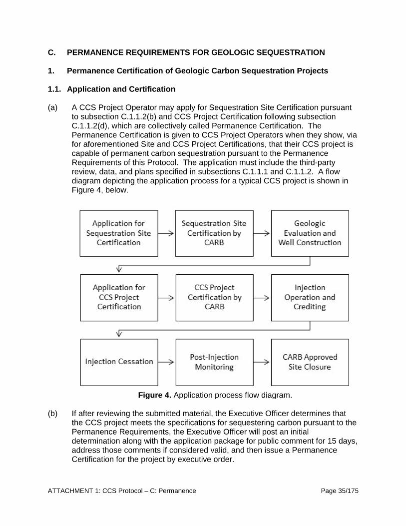
to subsection C.1.1.2(b) and CCS Project Certification following subsection C.1.1.2(d), which are collectively called Permanence Certification. The Permanence Certification is given to CCS Project Operators when they show, via for aforementioned Site and CCS Project Certifications, that their CCS project is capable of permanent carbon sequestration pursuant to the Permanence Requirements of this Protocol. The application must include the third-party review, data, and plans specified in subsections C.1.1.1 and C.1.1.2. A flow diagram depicting the application process for a typical CCS project is shown in Figure 4, below.
Figure 4. Application process flow diagram.
(b) If after reviewing the submitted material, the Executive Officer determines that
the CCS project meets the specifications for sequestering carbon pursuant to the Permanence Requirements, the Executive Officer will post an initial determination along with the application package for public comment for 15 days, address those comments if considered valid, and then issue a Permanence Certification for the project by executive order.

ATTACHMENT 1: CCS Protocol – C: Permanence Page 36/175
1.1.1. Third Party Review (a) Prior to submittal of a CCS project application to the Executive Officer for
Permanence Certification, the CCS Project Operator must have their application reviewed by a third party or parties that are mutually agreed upon by the Executive Officer and the applicant. The applicant is responsible for all costs of the application review.
(b) The third-party reviewer must certify that the data submitted as part of the application in subsection C.1.1.2 are true, accurate, and complete.
(c) The third-party reviewer must certify that the plans submitted as part of the application in subsection C.1.1.2 are sufficiently robust that, in their professional judgment, the CCS project is able to meet the permanence requirements for carbon sequestration.
(d) The third-party reviewer must certify that the Site-Based Risk Assessment submitted as part of the application in subsection C.1.1.2 is accurate and complete, and that the risks identified are either sufficiently monitored or sufficiently remediated in the Emergency and Remedial Response Plan submitted in the application.
1.1.2. Certification Application Materials All applications for Permanence Certification, pursuant to the Permanence Requirements, must include the following materials: (a) General Information Requirements:
(1) Statement of the primary purpose of the project;
(2) A brief description of the nature of the business;
(3) The name, mailing address, and latitude and longitude of the CCS project or
well for which the Permanence Certification is submitted;
(4) The operator’s name, address, telephone number, ownership status, and status as a federal, state, private, public, or other entity;
(5) The activities conducted by the operator which would require it to obtain permits under RCRA, the U.S. EPA UIC program, the NPDES program under CWA, or the PSD program under CAA; and
(6) The activities conducted by the operator that would require it to obtain any drilling permits, valid access agreements, or any encroachment permits under
ATTACHMENT 1: CCS Protocol – C: Permanence Page 37/175
county or city guidelines, or any federal, state, or local air, water, or restricted land use operating permits.
(7) A listing of all permits or construction approvals received or applied for and their status under any of the following programs:
(A) Hazardous Waste Management program under RCRA;
(B) U.S. EPA UIC program under SDWA;
(C) NPDES program under CWA;
(D) PSD program under CAA;
(E) Nonattainment program under CAA;
(F) NESHAPS preconstruction approval under CAA;
(G) Dredge and fill permits under section 404 of Clean Water Act; and
(H) Other relevant environmental permits such as federal, state, county, or city permits.
(b) Application for Sequestration Site Certification:
(1) Site-Based Risk Assessment pursuant to subsection C.2.2, including a Risk
Management Plan following subsection C.2.2(c);
(2) The following plans:
(A) A Geologic Evaluation pursuant to subsection C.2.3, including a Formation Testing and Well Logging Plan following subsections C.2.3.1 and C.2.3.1(a);
(B) An Area of Review (AOR) Delineation and Corrective Action Plan pursuant to subsection C.2.4, including a description of the computational model used following subsection C.2.4.1 and the results of the AOR delineation modeling following subsection C.2.4.2;
(C) Baseline Surface and Near-Surface Testing Plan pursuant to subsection C.2.5(a);
(D) Well Construction Plan pursuant to subsection C.3.1(b), Pre-Injection Testing Plan (subsection C.3.2(b)), and a plan describing the proposed operating requirements and restrictions (subsection C.3.3(a));

ATTACHMENT 1: CCS Protocol – C: Permanence Page 38/175
(E) A Testing and Monitoring Plan pursuant to subsection C.4.1, including plans for mechanical integrity testing (subsection C.4.2), emissions monitoring (subsection C.4.3.1), and monitoring, measurement, and verification of containment (subsection C.4.3.2);
(F) A Well Plugging and Abandonment Plan pursuant to subsection C.5.1;
(G) A Post-Injection Site Care and Site Closure Plan pursuant to subsection C.5.2; and
(H) An Emergency and Remedial Response Plan pursuant to subsection C.6;
(3) The following demonstrations:
(A) A Financial responsibility demonstration pursuant to subsection C.7;
(B) A Legal understanding demonstration pursuant to subsection C.9; and
(C) Any other plans or information required by the Executive Officer in order to evaluate the application for Sequestration Site Certification.
(c) Sequestration Site Certification will be implemented by an executive order from
CARB.
(d) Application for CCS Project Certification:
(1) Any updates to information or plans from subsection C.1.1.2(b);
(2) Formation testing and well logging report pursuant to subsection C.2.3.1(l);
(3) Corrective action report pursuant to subsection C.2.4.3(c);
(4) Baseline surface and near-surface testing report pursuant to subsection C.2.5(f);
(5) Well construction and pre-injection testing report pursuant to subsections C.3.1(b) and C.3.2(c); and
(6) Any other information required by the Executive Officer that is necessary to evaluate the application for CCS Project Certification.
(e) CCS Project Certification will be implemented by an executive order from CARB. 1.1.3. Reporting 1.1.3.1. Electronic Reporting

ATTACHMENT 1: CCS Protocol – C: Permanence Page 39/175
(a) The CCS Project Operator must submit to the Executive Officer any reports,
submittals, notifications, and records made and maintained by the operator under this Permanence Certification in an electronic format. The accuracy of all electronic submissions must be attested to at the time of submission.
(b) The CCS Project Operator is solely responsible for ensuring that the Executive Officer receives its reports, submittals, notifications, and records as required in this section. For the Executive Officer to be able to deem an electronically submitted report to be valid, the report must be accompanied by a digital signature that meets the requirements of California Code of Regulations, title 2, sections 22000 et seq.
1.1.3.2. Quarterly or Annual Reporting (a) For crediting purposes, CCS Project Operators are required to submit quarterly
or annual (depending on how often the project elects to undergo verification) reports of GHG emissions reductions and ongoing monitoring results. Reports must include measurements of relevant parameters sufficient to ensure that the quantification and documentation of CO2 sequestered is replicable and verifiable pursuant to the Accounting Requirements in section B. Data quality management must be sufficient to support quantification and verification of CO2 sequestered.
(b) CCS Project Operators must submit quarterly or annual reports that include:
(1) All metered measurements of inputs to GHG emissions reductions as calculated in subsection B.2.2;
(2) Analysis of the CO2 stream following subsection C.4.3.1.1(b); and
(3) Injection rate and volume pursuant to subsection C.4.3.1.2(e).
(c) Quarterly and annual reports must be submitted by the deadlines in Table 1.
Table 1. Quarterly and Annual Reporting Calendar
Deadline Report January 31 Annual report for the prior year March 31 Submit final Q4 report June 30 Submit final Q1 report September 30 Submit final Q2 report
1.1.3.3. Annual Reporting
ATTACHMENT 1: CCS Protocol – C: Permanence Page 40/175
(a) For crediting purposes, CCS Project Operators are required to submit annual reports of GHG emissions reductions, project operations, and ongoing monitoring results. Reports must include measurements of relevant parameters sufficient to ensure that the quantification and documentation of CO2 sequestered is replicable and verifiable pursuant to the Accounting Requirements in section B and the Permanence Requirements in section C. Data quality management must be sufficient to support quantification and verification of CO2 sequestered. If there are no changes to the plans, pursuant to subsection C.1.1.3, and if acceptable to the Executive Officer, the CCS Project Operator may submit a report demonstrating how they are following the plans.
(1) CCS Project Operators must submit annual reports that include:
(A) Metered measurements of all annual GHG emissions reductions as calculated in subsection B.2.2;
(B) The results of operational parameters and emissions and containment monitoring pursuant to subsections C.3.4, C.4.3.1, and C.4.3.2;
(C) A summary of any incidents or changes in operational parameters that triggered an AOR reevaluation following subsections C.2.4.4, C.2.4.4.1, and C.3.4;
(D) A summary of any incidents that required implementation of emergency and remedial response pursuant to subsection C.6;
(E) Mechanical integrity testing results of project wells pursuant to subsection C.4.2.1, as well as reports documenting any incidents where the loss of mechanical integrity occurred and a demonstration of the actions taken by the CCS Project Operator to mitigate or repair the well;
(F) Results of pressure fall-off testing of injection wells at least once every five years pursuant to subsection C.4.3.1.5(a). Pressure fall-off testing results must be submitted to the Executive Officer in writing within 30 days following the test, and the results of these tests must be amended to the annual report pursuant to subsection C.4.3.1.5(e);
(G) A report of any corrective action taken by the CCS Project Operator and a justification for why and how the corrective action was implemented, pursuant to subsection C.2.4.3;
(H) The results of each AOR reevaluation, to be performed no less than once every five years, pursuant to subsections C.2.4.4(a)(5), C.2.4.4(c)(2), and C.2.4.4(c)(5); and
(I) Any other information required by the Executive Officer.

ATTACHMENT 1: CCS Protocol – C: Permanence Page 41/175
(b) Annual reports must be submitted by the January 31 for the preceding year
(Table 1). 1.1.3.4. Advanced Notice Reporting (a) Well tests: The CCS Project Operator must give at least 30 days advance written
notice to the Executive Officer of any planned mechanical integrity test or workover.
(b) Planned Changes: The CCS Project Operator must give written notice to the Executive Officer, as soon as possible, of any planned physical alterations or additions to the injection project other than minor repair/replacement or maintenance activities. An analysis of any changes to the composition of the injection fluid must be submitted to the Executive Officer for review and written approval at least 30 days prior to injection; this approval may result in a CCS project certification modification.
1.1.3.5. Noncompliance and Event Reporting (a) In the event of an emergency that falls into the “major” or “serious” emergency
category pursuant to subsection C.6.1(b) and requires implementation of response actions pursuant to the Emergency and Remedial Response Plan, subsection C.6, the CCS Project Operator must report to the Executive Officer and any relevant local or state agency (including DOGGR and the California Governor’s Office of Emergency Management, if the CCS project is in California), or equivalent. Any information must be provided orally and in an electronic format within 24 hours from the time the CCS Project Operator becomes aware of the circumstances. Such reports must include, but not be limited to the following information:
(1) Any evidence of whether the injected CO2 stream or associated pressure front may endanger public health, or any monitoring or other information which indicates that any contaminant may endanger public health;
(2) Any evidence of noncompliance with a Permanence Certification condition, or malfunction of the injection system, which may cause an uncontrolled release of fluid or gas out of the storage complex that is likely to reach the atmosphere;
(3) Any triggering of the shut-off system required in subsection C.3.3(g) (e.g., downhole or at the surface) or incident specified in subsection C.3.4;
(4) Any failure to maintain mechanical integrity;
ATTACHMENT 1: CCS Protocol – C: Permanence Page 42/175
(5) Pursuant to compliance with the testing and monitoring requirements in subsection C.4.3.2, any uncontrolled release of CO2 outside of the storage complex that may reach the atmosphere; and
(6) Actions taken to implement appropriate protocols outlined in the Emergency Remedial Response Plan (subsection C.6).
(b) A written submission must be provided to the Executive Officer within five business days of the time the CCS Project Operator becomes aware of the circumstances described in subsection C.1.1.3.5(a). The submission must contain a description of any noncompliance and its cause, the period of noncompliance, including exact dates and times, and, if the noncompliance has not been corrected, the anticipated time it is expected to continue as well as actions taken to implement appropriate protocols outlined in the Emergency and Remedial Response Plan, and steps taken or planned to reduce, eliminate, and prevent recurrence of the noncompliance.
1.1.3.6. Additional Reporting (a) Noncompliance: The CCS Project Operator must report all instances of
noncompliance not otherwise reported in subsection C.1.1.3.5 with the next quarterly monitoring report. The reports must contain the information listed in subsection C.1.1.3.5(b).
(b) Well plugging and abandonment: CCS Project Operators must submit, in writing, a Notice of Intent to Plug 30 days before plugging any well that is part of the CCS project pursuant to subsection C.5.1(h). If amendments to the Well Plugging and Abandonment Plan are necessary, a revised plan must be submitted with the notice of intent, following subsection C.5.1(i). Within 60 days of plugging, the CCS Project Operator must submit a plugging report pursuant to subsection C.5.1(k).
(c) Other information: When the CCS Project Operator becomes aware of failure to submit any relevant facts in the Permanence Certification or that incorrect information was submitted in a Permanence Certification or in any report to the Executive Officer, the CCS Project Operator must submit such facts or corrected information within 10 days.
1.1.4. Recordkeeping (a) The CCS Project Operator must retain records and all monitoring information,
including all calibration and maintenance records and all original chart recordings for continuous monitoring instrumentation and copies of all reports required by the Permanence Certification (including records from pre-injection, active injection, and post-injection phases) for a period of 10 years after site closure.
ATTACHMENT 1: CCS Protocol – C: Permanence Page 43/175
(b) The CCS Project Operator must maintain records of all data required to complete the Permanence Certification and any supplemental information (e.g. modeling inputs for AOR delineations and reevaluations, plan modifications, etc.) submitted under subsection C.1.1.2 and reports submitted under subsection C.1.1.3, for a period of at least 10 years after site closure.
(c) The CCS Project Operator must retain records concerning the nature and composition of all injected fluids until 10 years after site closure.
(d) The retention periods specified in subsections C.1.1.4(a) and C.1.1.4(b) may be extended by request of the Executive Officer at any time. The CCS Project Operator must continue to retain records after the retention period specified in subsections 1.1.4(a) and 1.1.4(b) or any requested extension thereof expires unless the operator delivers the records to, or obtains written approval from, the Executive Officer to discard the records.
1.2. Terms and Conditions (a) Any changes to the operational parameters of a Permanence Certification are
subject to approval by the Executive Officer and must be noted in either an addendum to the a Permanence Certification or a revised Permanence Certification.
(b) The Permanence Certification is non-transferable.
(c) Permanence Certification must expire, and be deemed null and void, upon the first day following 24 consecutive months of no injection at the GSC project, and a new approval process and re-certification would be required prior to restarting injection.
2. Site Characterization 2.1. Minimum Site Selection Criteria (a) As part of the application for Sequestration Site Certification, the CCS Project
Operator must demonstrate that the geologic system comprises:
(1) A sequestration zone of sufficient volume, porosity, permeability, and injectivity to receive the total anticipated volume of the CO2 stream;

ATTACHMENT 1: CCS Protocol – C: Permanence Page 44/175
(2) A minimum injection depth of 800 m (2,600 ft), or the depth corresponding to pressure and temperature conditions where CO2 exists in a supercritical state (>31°C and >7 MPa);5
(3) A confining layer free of transmissive faults or fractures and of sufficient areal extent, integrity, thickness, and ductility to contain the injected CO2 stream and displaced formation fluids and allow injection at proposed maximum pressures and volumes without initiating or propagating fractures in the confining layer; and
(4) A minimum of one additional permeable stratum6 (dissipation interval) situated directly above the sequestration zone and confining layer, with at least one impermeable confining layer (secondary confining layer) between the surface and the dissipation interval. The sequestration zone, primary confining layer, dissipation interval(s), and secondary confining layer(s) define the storage complex. The purpose of the dissipation interval is to (1) dissipate any excess pressure caused by CO2 injection, (2) impede vertical migration of CO2 and/or brine above the storage complex, potentially to the surface and atmosphere via possible leakage paths, and (3) provide additional opportunities for monitoring, measurement, and verification of containment.
(5) Depending on the distance between the sequestration zone and basement rock, the Executive Officer may require the CCS Project Operator to identify and characterize additional dissipation interval(s) below the storage complex to limit the extent of downward overpressure propagation and lower the potential for induced seismicity within formations beneath the injection zone.
2.2. Risk Assessment
(a) As part of the application for Sequestration Site Certification, the CCS Project Operator must complete a Site-Based Risk Assessment that describes the potential pathways for leaks or migration of CO2 out of the storage project from the CCS project and the potential scenarios that could occur as a result.
(b) At a minimum the risk assessment must examine the scenarios in the
Emergency and Remedial Response Plan under subsection C.6.1(a). Any other risks that could be reasonably anticipated must be included.
5 Lin, H., Takashi, F., Reisuke, T., Takahashi, T., and Hashida, T., Experimental evaluation of interactions in supercritical CO2/water/rock minerals system under geologic CO2 sequestration conditions (2008) Journal of Materials Science, v. 43, n. 7, p. 2307–2315. 6 C., Oldenburg, P.D., Jordan, and E., Burton, 2017, Recommendations for Geologic Carbon Sequestration in California: I. Siting Criteria and Monitoring Approaches, II. Example Application Case Study, Energy Geosciences Division, Lawrence Berkeley National Laboratory.
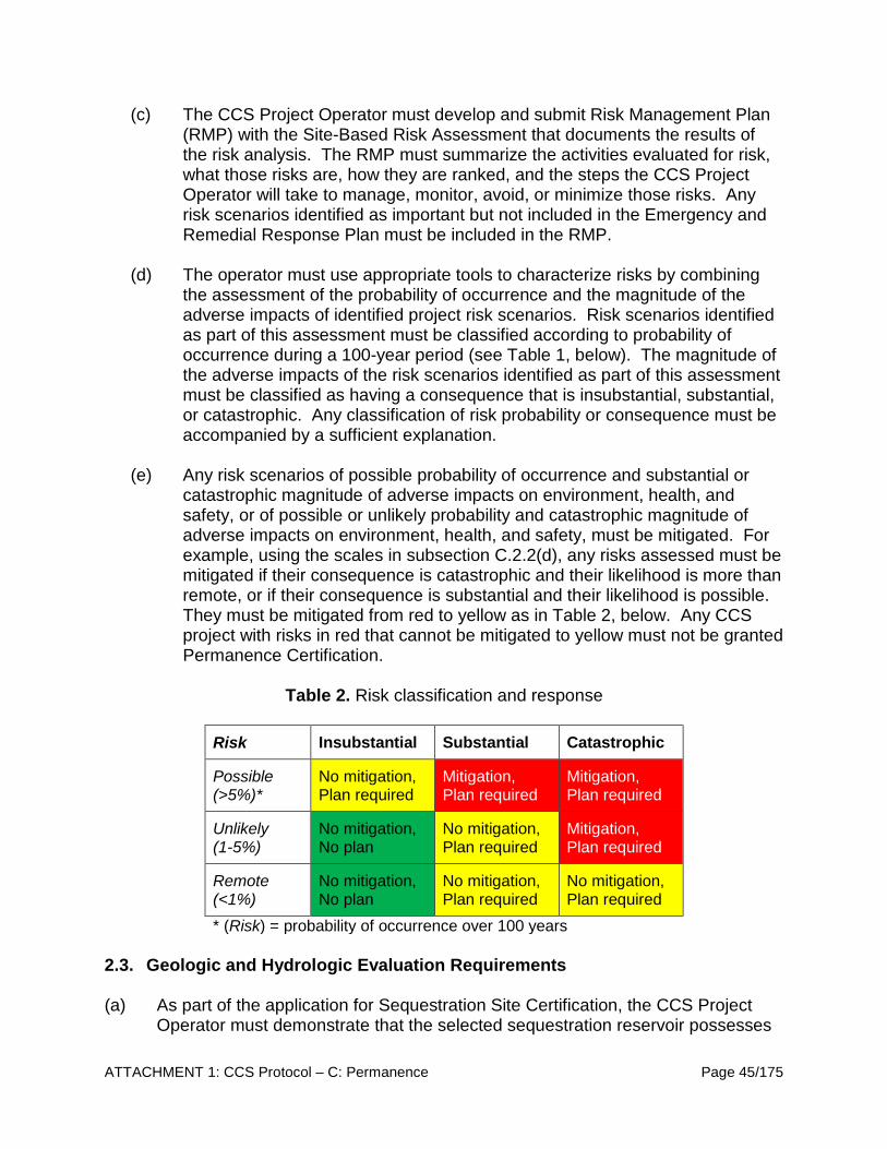
ATTACHMENT 1: CCS Protocol – C: Permanence Page 45/175
(c) The CCS Project Operator must develop and submit Risk Management Plan (RMP) with the Site-Based Risk Assessment that documents the results of the risk analysis. The RMP must summarize the activities evaluated for risk, what those risks are, how they are ranked, and the steps the CCS Project Operator will take to manage, monitor, avoid, or minimize those risks. Any risk scenarios identified as important but not included in the Emergency and Remedial Response Plan must be included in the RMP.
(d) The operator must use appropriate tools to characterize risks by combining
the assessment of the probability of occurrence and the magnitude of the adverse impacts of identified project risk scenarios. Risk scenarios identified as part of this assessment must be classified according to probability of occurrence during a 100-year period (see Table 1, below). The magnitude of the adverse impacts of the risk scenarios identified as part of this assessment must be classified as having a consequence that is insubstantial, substantial, or catastrophic. Any classification of risk probability or consequence must be accompanied by a sufficient explanation.
(e) Any risk scenarios of possible probability of occurrence and substantial or
catastrophic magnitude of adverse impacts on environment, health, and safety, or of possible or unlikely probability and catastrophic magnitude of adverse impacts on environment, health, and safety, must be mitigated. For example, using the scales in subsection C.2.2(d), any risks assessed must be mitigated if their consequence is catastrophic and their likelihood is more than remote, or if their consequence is substantial and their likelihood is possible. They must be mitigated from red to yellow as in Table 2, below. Any CCS project with risks in red that cannot be mitigated to yellow must not be granted Permanence Certification.
Table 2. Risk classification and response
Risk Insubstantial Substantial Catastrophic
Possible (>5%)*
No mitigation, Plan required
Mitigation, Plan required
Mitigation, Plan required
Unlikely (1-5%)
No mitigation, No plan
No mitigation, Plan required
Mitigation, Plan required
Remote (<1%)
No mitigation, No plan
No mitigation, Plan required
No mitigation, Plan required
* (Risk) = probability of occurrence over 100 years 2.3. Geologic and Hydrologic Evaluation Requirements (a) As part of the application for Sequestration Site Certification, the CCS Project
Operator must demonstrate that the selected sequestration reservoir possesses
ATTACHMENT 1: CCS Protocol – C: Permanence Page 46/175
sufficient volume and injectivity to contain the proposed storage volume of CO2 and that the injected fluid will not migrate out of the approved storage complex through geologic structures, including faults, fractures, and other high permeability zones, such as breccia zones.
(b) The geologic characterization requires information on the lithology, structure, hydrogeologic, and geomechanical properties of the proposed sequestration reservoir, as well as the over- and underlying formations where potential gas or fluid migration could occur, following subsection C.2.3(c).
(c) CCS Project Operators are required to submit, with the application for Sequestration Site Certification, an evaluation of the geological and hydrological characteristics of the sequestration zone and confining layer derived from academic journals, historical records, laboratory and field data such as geologic core samples, outcrop data, well logs, two- and three-dimensional seismic surveys, and names and lithologic descriptions. The CCS Project Operator must submit the following information:
(1) Regional geologic information:
(A) A brief synopsis of the geologic history of the CCS project site;
(B) Porosity, permeability, lithofacies, depositional environment, and the geologic names and ages of formations;
(C) Regional hydrogeology of the sequestration zone, including all available
data pertaining to groundwater flow direction, flux, and flow patterns; and (D) Structural geology of the regional area, including faults and fault
orientations, the presence and trends of folds, and whether these structures penetrate into the storage complex.
(2) Site-specific geologic and hydrogeologic information:
(A) Depth interval of confining layer and sequestration zone below ground
surface and depth interval of planned perforation interval; (B) Lithologic description from core or hand samples, including petrology,
mineralogy, grain size, sorting or grading, cementation and dissolution features, and lithofacies or geologic rock name for both the confining layer and sequestration zone;
(C) Structural geology of the local area including faults and fault orientations,
the presence and trends of folds, and whether these structures penetrate into the storage complex;
ATTACHMENT 1: CCS Protocol – C: Permanence Page 47/175
(D) Confining layer and sequestration zone thickness, as well as total thicknesses of both the confining layer and the sequestration reservoir, thicknesses of any high permeability or porosity intervals in the sequestration zone (if applicable), and thicknesses of planned perforated interval(s); and
(E) Porosity, permeability, and capillary pressure of the sequestration zone
and confining layer and perforation interval. These data must be used in the calculation of the following properties of the sequestration zone and confining layer:
1. Hydraulic conductivity;
2. Specific storage; and
3. Storage coefficient.
(3) Site-specific geomechanical and petrophysical information:
(A) Fracture/parting pressure of the sequestration zone and confining layer,
and the corresponding fracture gradients determined via step rate or leak-off tests performed in the wellbore. For new CCS projects, these testing and logging activities may be undertaken during the drilling of a stratigraphic test well, or during the drilling and construction of any new injection, production, observation, or monitoring well;
(B) Rock compressibility, or a similar estimation of the measure of rock strength, for the confining layer and sequestration zone;
(C) Rock strength and the ductility of the confining layer. Rock strength is usually determined by performing a triaxial load test of the uniaxial compressive strength (UCS) on a core sample. Ductility and rock strength must be assessed via the following equations:
1. Ductility of the confining layer must be calculated using the following brittleness index (BRI):
𝐵𝐵𝐵𝐵𝐵𝐵 =𝑈𝑈𝐶𝐶𝑈𝑈𝑈𝑈𝐶𝐶𝑈𝑈𝑁𝑁𝑑𝑑
(7)
Where UCS is the unconfined compressive strength of the confining layer as measured from intact samples, and the UCSNC is the confining layer’s compressive strength if it was normally consolidated, as measured from remolded samples that are normally reconsolidated;

ATTACHMENT 1: CCS Protocol – C: Permanence Page 48/175
2. UCS can also be estimated from the pressure wave velocity (Vp) through intact samples or measured in situ within the wellbore via the equation:
log(𝑈𝑈𝐶𝐶𝑈𝑈) = −6.36 + log�0.86𝑉𝑉𝑝𝑝 − 1172� (8)
3. The UCSNC can also be estimated from the effective vertical stress (σ’), where:
𝑈𝑈𝐶𝐶𝑈𝑈𝑁𝑁𝑑𝑑 = 0.5𝜎𝜎′ (9) If BRI < 2, the confining layer is sufficiently ductile to anneal any discontinuities. If BRI > 2, discontinuities may be open.
(D) Pore pressure, or the measure of in situ fluid pressure, formation temperature; and
(E) Estimation of the injection volume and the maximum allowable injection rate and pressure, such that neither the confining layer nor the sequestration zone hydraulically fracture during injection, must be based on step rate test results as in subsection C.2.3.1(h).
(4) Injectivity or pump tests of the sequestration zone based on CO2 reservoir flow modeling using information determined from subsection C.2.3.1(i).
(5) Geologic characteristics of any secondary confining layers above the primary confining layer and below the sequestration zone, as well as characteristics of any dissipation intervals above and below the target sequestration zone and confining layer.
(6) A full description of all geologic structures, including faults and fractures, which intersect the storage complex and all data relevant to assessing the transmissivity of these features. The CCS Project Operator should include a determination that these features will not interfere with containment, supported by information including, but not limited to:
(A) The location, depth, displacement, and geometry of the fault or fracture;
(B) Data on aperture, cement, and fault gauge;
(C) The orientation of the local state of stress and a full geometric description
in support of modeling the response to changes in the state of stress during injection; and

ATTACHMENT 1: CCS Protocol – C: Permanence Page 49/175
(D) Any additional methods and results of fault stability analyses and comparison to anticipated or modeled pressures during injection.
(7) An evaluation of the seismic history of the proposed sequestration site, including the date, magnitude, depth, and location of the epicenter of seismic sources and a determination that the seismicity would not cause a catastrophic loss of containment, either by breaching the integrity of the well or the sequestration formation, following a risk assessment pursuant to subsection C.2.2(e);
(8) A tabulation of readily available information on freshwater aquifers and springs in the AOR. This information should include:
(A) The numbers, thicknesses, and lithologies of freshwater aquifers, including interbedded and low permeability zones;
(B) Water quality such as TDS, alkalinity, pH, dissolved trace metals, and TOC;
(C) The deepest depth of freshwater aquifers;
(D) Whether any freshwater aquifers in the AOR are currently accessed for human use; and
(E) The location and distance to nearest water supply well and nearest downgradient water supply well, as well as any water wells and springs in the AOR.
(9) A tabulation of readily available geochemical data on subsurface formations and formation fluids in and around the storage complex, including:
(A) Reservoir fluid data for the sequestration zone, such as TDS, dynamic viscosity, density, temperature, pH, and information on the potentiometric surface, if available;
(B) Characteristics of any aquifers directly above or below the sequestration zone, if applicable, including TDS, temperature, and information on the potentiometric surface, if available; and
(C) For CO2-EOR and depleted oil and gas reservoir sites, data such as oil gravity and viscosity, presence, concentrations, and specific gravity of non-hydrocarbon components in the associated gas (e.g. hydrogen sulfide), and any other compositional data as needed for modeling fluid interactions.

ATTACHMENT 1: CCS Protocol – C: Permanence Page 50/175
(10) The location and description of any mineral deposits or other natural resources beneath or near the AOR, including but not limited to stone, sand, clay, gravel, coal, oil, and natural gas.
(d) Characterization of other injection or production fluids in or near the AOR:
(1) CCS Project Operator must describe and quantify any fluids injected or produced related to the CCS project, in addition to the injection fluid.
(2) The CCS Project Operator must provide a management strategy for all of the
following:
(A) The potential release of production fluid must be mitigated pursuant to the Emergency and Remedial Response Plan from subsection C.6.1;
(B) Other injection, such as waste water disposal, must be considered in
regards to pressure changes and the geomechanical response to such injection; and
(C) Distant parameters, such as production or disposal, should be considered
in the boundary conditions of the computational model parameters pursuant to subsection C.2.4.1.
(e) Site-specific maps and cross-sections, including:
(1) Geologic and topographic maps and cross-sections illustrating regional
geology, hydrogeology, and geologic structure of the local area;
(2) Maps and stratigraphic cross-sections indicating the general vertical and lateral limits of all freshwater aquifers, water wells, and springs within the AOR, their positions relative to the storage complex, and the direction of shallow groundwater movement, where known;
(3) Structural contour and isopach maps of the storage complex in the AOR including all faults and fractures, as well as any lateral containment features;
(4) Stratigraphic columns or cross-sections of the regional basin showing lateral continuity of storage complex, as well as the lack of any significant compartmentalization or heterogeneity in the sequestration zone that could inhibit proposed injection volumes;
(5) Representative electric log to a depth below the sequestration zone and lower confining layer or dissipation interval(s) identifying all geologic units, formations, freshwater aquifers, and oil or gas zones. If CO2 injection is for CO2-EOR, the electric log must extend to a depth below the deepest producing zone;
ATTACHMENT 1: CCS Protocol – C: Permanence Page 51/175
(6) At least one cross-section in the AOR through the injection well;
(7) Maps showing the locations of any seismic lines and cross-sections; and
(8) Maps showing any known mineral deposits or natural resources within the
AOR.
(f) Description of any accumulation of gas within the AOR, including but not limited to, the type of gas, location, depth, and areal extent on the surface.
(g) Any additional information requested by the Executive Officer that is necessary to complete the geological and hydrogeological site evaluation.
2.3.1. Formation Testing and Well Logging Program (a) As part of the application for Sequestration Site Certification, the CCS Project
Operator must submit a Formation Testing and Well Logging Plan. The plan must demonstrate to the Executive Officer how the CCS Project Operator will collect the geologic and hydrogeologic data required to show that the selected storage complex is suitable for receiving and containing injected CO2.
(b) This section provides guidance on the formation testing and well logging activities that the CCS Project Operator must conduct to generate the information and data required to confirm that the storage complex is able to meet the permanence requirements for carbon sequestration, as required in subsection C.1.1.2.
(c) For new CCS projects, the testing and logging activities described in subsections C.2.3.1(e) through C.2.3.1(j) may be undertaken during and after drilling of a stratigraphic test well, or during and after the drilling and construction of any new injection, production, observation, or monitoring well.
(d) For a CO2 injection well to be transitioned from a pre-existing injection, monitoring, stratigraphic test, or production well, the testing and logging information required by subsections C.2.3.1(e) through C.2.3.1(j) can be provided from previous and ongoing testing and monitoring of the formation and from well tests and logs conducted during the previous use of the well.
(e) Well logging requirements:
(1) During the drilling and construction of a CCS project injection well, the CCS Project Operator must run appropriate logs, conduct surveys, and perform tests to determine or verify the depth, thickness, porosity, permeability, lithology, and salinity of all relevant geologic formations.

ATTACHMENT 1: CCS Protocol – C: Permanence Page 52/175
(2) Well logging activities must be used to supplement data on the geologic and hydrogeologic properties of relevant subsurface formations collected during initial site characterization and to support building a conceptual understanding of the site, conducting the AOR determination, and designing the CCS project.
(3) Well logging results must also be used to establish baseline data against which to compare to future measurements under subsection C.2.5, and to ensure conformance with the injection well construction requirements under subsection C.3.1.
(4) CCS Project Operators must use well logging results to create a temperature vs. depth and hydrostatic pressure profile, which should be used to inform the risk evaluation (subsection C.2.2) and monitoring (subsection C.4.3).
(f) Core analyses:
(1) The CCS Project Operator must take whole cores or sidewall cores of the sequestration zone and confining layer, and formation fluid samples from the sequestration zone, during drilling and prior to well construction. The cores of the sequestration zone and confining layer must be collected during the initial stages of project development, from a stratigraphic well or from the injection well itself, pursuant to the needs of the operator. The CCS Project Operator must submit to the Executive Officer a detailed report prepared by an experienced log analyst that includes: well log data and analyses (including the logs themselves), core analyses, and formation fluid sample information.
(2) Information from cores must be used to refine site characterization data submitted pursuant to subsection C.1.1.2.
(3) The Executive Officer may accept information on cores from nearby wells that were previously collected if the CCS Project Operator can demonstrate that core retrieval is not possible and that such cores are representative of conditions at the well site.
(4) Core logs must include descriptions or indications of the following characteristics: lithology, thickness, grain size, sedimentary structures, diagenetic features, geologic contacts, textural maturity, oil staining, fracturing, and porosity.
(5) Laboratory analysis of cores must include petrology and mineralogy, petrophysical properties, and geomechanical properties, including but not limited to, relative permeability, capillary pressure, fluid compatibility, wettability, and pore volume compressibility.
ATTACHMENT 1: CCS Protocol – C: Permanence Page 53/175
(6) The Executive Officer may require the CCS Project Operator to take core samples of other formations in the wellbore, such as dissipation intervals or secondary confining layers in the stratigraphic column, in order to characterize the mitigation potential of over- and underlying geologic formations.
(g) Characterization of the chemical and physical properties and downhole
conditions of fluids in the sequestration zone: (1) Upon completion of the injection well and prior to operation, the CCS
Project Operator must collect data on downhole conditions needed to support monitoring and modeling design. The CCS Project Operator must justify the sufficiency of the data collected, and that the method by which it was collected and analyzed is suitable for the purposes to which it is applied. The following data are required:
(A) Fluid temperature, pH, conductivity, reservoir pressure, fluid density, and static fluid level of the sequestration zone.
(2) If geochemical data are to be used for monitoring, a site-specific
procedure to separate leakage signal from background must be developed. For example, dissolved gases must be assessed with correction for pressure and temperature effects; and
(3) The CCS Project Operator must submit the results of all downhole analyses and any laboratory results on samples, including quality assurance samples (e.g., blanks, duplicates, matrix spikes).
(h) Fracture/parting pressure of the sequestration zone and confining layer:
(1) The CCS Project Operator must perform step rate tests for each CO2 injection well that is part of the CCS project, and use the results of each test to determine the fracture pressure of the sequestration zone and confining layer.
(A) The CCS Project Operator must report the results of all step rate tests for each CO2 injection well. Such data must be used to determine the maximum allowable injection pressure for the CCS project such that injection will not initiate or propagate faults of fractures in the sequestration zone or confining layer; and
(B) Step rate tests must meet the following requirements: (1) real time downhole pressure recording must be employed, (2) bottom-hole pressure must be recorded at a zero injection rate for at least one full time step before the first step of the step rate test, and before one full time step after the last step of the step rate test, and (3) step rate test data reported
ATTACHMENT 1: CCS Protocol – C: Permanence Page 54/175
under subsection C.1.1.2 must be raw and unaltered, and include the injection rate, bottom-hole pressure, surface pressure, pump rate volume, and time recorded continuously at a rate of every one second during the step rate test.
(2) The CCS Project Operator must also discuss how the calculated fracture pressure compares with data from core tests or other wells in the area, if available.
(i) Hydrogeologic testing:
(1) Upon completion of the injection well, prior to operation, the CCS Project Operator must conduct the following tests to verify hydrogeologic characteristics of the sequestration zone:
(A) A pressure fall-off test; and
(B) A pump test; or
(C) Injectivity tests.
(2) These tests must be designed to determine the injectivity of the sequestration zone to set operating limits for CO2 injection rates and volumes; and
(3) Pressure fall-off tests must be conducted to verify hydrogeologic parameters, including but not limited to, the transmissibility of the sequestration zone, the static sequestration zone pressure, the skin factor, and to identify faults or fractures adjacent to the wellbore.
(j) The CCS Project Operator must determine or calculate additional physical and chemical characteristics of the sequestration zone and confining layer to augment other information gathered during the site characterization process, support the development of the AOR delineation model, or support setting of permit conditions (e.g., operational limits).
(k) The CCS Project Operator must provide the Executive Officer with the opportunity to witness all logging and testing in this subsection. A state licensed engineer, or equivalent, may be allowed to witness logging and testing, if approved by the Executive Officer.
(l) The CCS Project Operator must submit a descriptive report that includes an
interpretation of the results of the formation testing and well logging program with the application for CCS Project Certification. At a minimum, the report must include:
(1) The results of each test, log, and any supplemental data;
ATTACHMENT 1: CCS Protocol – C: Permanence Page 55/175
(2) An interpretation of the tests and logs, including any assumptions, and the
determination of the sequestration zone and confining layer characteristics, including porosity, permeability, lithology, thickness, depth, and formation fluid salinity of relevant geologic formations;
(3) Any changes in interpretation of site stratigraphy based on formation testing
and well logs; and (4) A description of any alternative methods used that provide equivalent or
better information, and that are required and approved by the Executive Officer.
(5) The CCS Project Operator must demonstrate that the information collected is
consistent with other available site characterization data submitted with the Permanence Certification and that the data support other assessments of stratigraphy and formation properties. The Executive Officer may compare the results of formation testing logs from different wells in the vicinity to interpret local stratigraphy, and verify the depths and properties of the proposed sequestration zone and confining layer.
2.4. Area of Review Delineation and Corrective Action (a) The AOR and corrective action requirements are to ensure that the areas
potentially impacted by a proposed GSC project are delineated, all wells that need corrective action receive it, and that this process is updated throughout the active life of the CCS project. The general relationship between site characterization, modeling, and monitoring activities at a CCS project is shown on Figure 5.
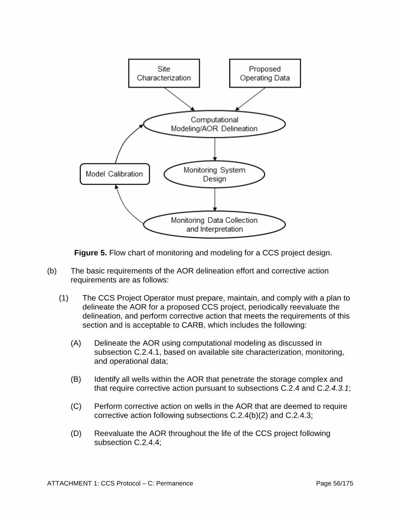
ATTACHMENT 1: CCS Protocol – C: Permanence Page 56/175
Figure 5. Flow chart of monitoring and modeling for a CCS project design.
(b) The basic requirements of the AOR delineation effort and corrective action
requirements are as follows:
(1) The CCS Project Operator must prepare, maintain, and comply with a plan to delineate the AOR for a proposed CCS project, periodically reevaluate the delineation, and perform corrective action that meets the requirements of this section and is acceptable to CARB, which includes the following:
(A) Delineate the AOR using computational modeling as discussed in subsection C.2.4.1, based on available site characterization, monitoring, and operational data;
(B) Identify all wells within the AOR that penetrate the storage complex and that require corrective action pursuant to subsections C.2.4 and C.2.4.3.1;
(C) Perform corrective action on wells in the AOR that are deemed to require corrective action following subsections C.2.4(b)(2) and C.2.4.3;
(D) Reevaluate the AOR throughout the life of the CCS project following subsection C.2.4.4;
ATTACHMENT 1: CCS Protocol – C: Permanence Page 57/175
(E) Ensure that the Emergency and Remedial Response Plan and financial responsibility demonstration account for the most recently approved AOR; and
(F) Retain all modeling inputs and data used to support initial AOR delineations and AOR reevaluations for the life of the CCS project and 10 years following site closure.
(2) AOR and Corrective Action Plan:
(A) As a part of the application for Sequestration Site Certification, the CCS Project Operator must submit an AOR and Corrective Action Plan that includes the following information:
(B) The method for delineating the AOR that meets the requirements of subsection C.2.4, including the model used, assumptions made, and site characterization data on which the model will be based; and
(C) A description of: 1. The minimum fixed frequency, not to exceed five years, at which the
CCS Project Operator will reevaluate the AOR and a justification for the proposed reevaluation frequency;
2. How monitoring and operational data (e.g., injection rate and pressure) will be used to inform an AOR reevaluation; and
3. How corrective action will be conducted to meet the requirements of subsection C.2.4, including what corrective action will be performed prior to injection, how corrective action will be adjusted if there are any changes in the AOR, and how site access will be guaranteed for future corrective action.
2.4.1. Computational Modeling Requirements (a) The CCS Project Operator must delineate the AOR using a computational model
that accounts for the physical properties and site characteristics of the sequestration zone and injected CO2 stream over the proposed life of the CCS project via the following actions:
(1) The computational model of the AOR must incorporate various parameters including site characterization, monitoring, operational data, and:
(A) Predict the lateral and vertical migration of the free-phase CO2 plume and pressure front, as well as the dissolved CO2 plume and formation fluids in the subsurface, from either (1) the commencement of injection activities

ATTACHMENT 1: CCS Protocol – C: Permanence Page 58/175
until the plume stabilizes, or (2) until pressure differentials are no longer sufficient to lift either CO2 or brine into the subsurface above the storage complex;
(B) Be designed to simulate multiphase flow of several fluids (groundwater, CO2, and hydrocarbons, if present), phase changes of CO2, significant pressure changes, and any other pertinent processes in geologic media based on scientific principles and accepted mathematical and governing equations;
(C) Be based on detailed geologic, hydrogeologic, and geomechanical data collected for the characterization of the sequestration zone and confining layer. The CCS Project Operator must consider the following list of inputs when designing the model and must conduct sensitivity analysis and provide justification for any simplifications selected, based on site-specific conditions:
1. Regional and site-specific geology, such as stratigraphy, formation lithology, elevation, thickness, and structural geology (including faults, folding, fractures);
2. Pre-injection reservoir conditions including (1) hydrogeologic conditions such as intrinsic and relative permeabilities, porosity, capillary pressure, formation compressibility, water saturation, CO2 saturation, and storativity, and (2) reservoir fluid properties such as brine or hydrocarbon viscosity, density, composition or salinity, and compressibility;
3. Pre-injection geomechanical information on fracture pressure and gradient in the sequestration zone and confining layer, as well as any geomechanical processes or models that are incorporated into the AOR delineation effort based on initial site characterization efforts;
4. Existing or proposed operational and monitoring data, including fluid injection and withdrawal rates, injection bottom-hole pressure, groundwater characterization and monitoring systems (as recorded in, for example, verification wells), CO2 saturations and expected total volumes, the location and number of injection, production, and monitoring wells, and well construction details (total depth, perforated intervals, etc.);
5. Initial model parameters such as: (1) initial conditions (e.g., fluid pressures and flow rates, etc.) within the domain at the beginning of the model run, and (2) boundary conditions (i.e., the description of the conditions of the system) at the edges of the model domain and at the location of injection and/or extraction wells; and
ATTACHMENT 1: CCS Protocol – C: Permanence Page 59/175
6. Any other models, model parameters, and/or general assumptions that
are incorporated or considered for the CCS project and AOR delineation based on site-specific conditions. For example, mineral precipitation kinematic parameters may be introduced into a reactive transport model of the reservoir if the planned injectate and composition of water at depth are predicted, based on sampling and monitoring data, to react such that mineral precipitation may modify the permeability of the reservoir;
(D) Parameter values must be based on site data to the best extent possible.
In cases where certain detailed site geologic characterization data are unavailable, parameter values may be estimated from standard values or relationships in the scientific literature. CCS Project Operators must indicate the range of values possible for their site and conditions, and must provide a justification for using each particular parameter value not directly measured in the field or the laboratory;
(E) All data collected to comply with site characterization requirements must be considered in the AOR delineation. Any additional data available in the vicinity of the site that may affect the AOR delineation, e.g., from the U.S. Geological Survey or other wells drilled within the vicinity of the AOR must also be included in model development;
(F) Utilize appropriate equations of state and constitutive relationships derived from equilibrium phase relationships and empirically based approximations, respectively;
(G) Explicitly state model orientation and gridding parameters, including the spatial temporal domains, grid spacing and gridding routine, coordinate system, horizontal datum, and the physical properties and assumptions used to define the domain boundaries;
(H) Describe and justify the method and assumptions used to estimate the
value of the pressure front;
(I) Take into account any geologic heterogeneities, other discontinuities, data quality, and their possible impact on model predictions;
(J) Consider potential migration through faults, fractures, and artificial penetrations; and
(K) Perform sensitivity analysis on model input parameters and qualify the
model by assessing the implications of uncertainties in input data to the model predictions.
ATTACHMENT 1: CCS Protocol – C: Permanence Page 60/175
(2) The computer code utilized in an AOR delineation model must be open source and publically available to CARB and CCS Project Operators and, preferably, be reported in peer-reviewed CCS literature:
(A) The code used for modeling the AOR must, at a minimum, consider multiphase flow of CO2 in supercritical, liquid, and gaseous phases, including miscible and immiscible displacement, CO2 dissolution in groundwater, density-driven flow, and the impact of injection on groundwater flow patterns;
(B) Codes may also be further modified to allow for complex three-dimensional heterogeneous formations; residual phase trapping; characteristic-curve hysteresis; mineral precipitation/dissolution reactions and subsequent mineral phase trapping or leaching of heavy metals; and leakage through faults, fractures, and abandoned wellbores; and
(C) If using a non-peer-reviewed independently developed or untested code, the developer must verify the model’s accuracy by modeling test cases found in the literature before submitting the application for Sequestration Site Certification.
2.4.2. AOR Delineation using Computational Modeling Results (a) The initial site AOR delineation model must be submitted with the proposed AOR
and Corrective Action Plan in the application for Sequestration Site Certification pursuant to subsection C.1.1.2. The modeled AOR will be finalized after all site data are collected and pre-injection testing is complete.
(b) The AOR boundaries must be based on simulated predictions of the lateral extent of the separate-free-phase plume and pressure front for the cumulative CCS project model and must account for the anticipated injection rates from all planned injection wells.
(c) A single AOR modeling exercise may be conducted for all wells within a single CCS project.
(d) The application for Sequestration Site Certification submittal must include the following in support of the AOR delineation:
(1) Attributes of the code used to create the computational model, including the code name, name of the developing organization, and full accounting of or reference to the model governing equations, scientific basis, and any simplifying assumptions;
ATTACHMENT 1: CCS Protocol – C: Permanence Page 61/175
(2) A description of the model domain, such as the model’s lateral and vertical extents, geologic layer thickness, and grid cell sizes, as presented on maps and cross-sections;
(3) An accounting of all equations of state used for all modeled fluids (groundwater, CO2);
(4) Any constitutive relationships, such as relative-permeability saturation relationships, and how they were determined; and
(5) Model results, including predictions of the CO2 free-phase plume and pressure-front migration over the lifetime of the CCS project. Model results must be presented in contour maps, cross sections, and/or graphs showing plume and pressure front migration as a function of time, and that the application for Sequestration Site Certification submittal must include the outcome of parameter sensitivity analysis and model calibration.
2.4.3. Corrective Action Requirements (a) Corrective Action Plan:
(1) The CCS Project Operator is required to submit a Corrective Action Plan with
the initial application for Sequestration Site Certification pursuant to subsections C.1.1.2 and C.2.4.3(a). The AOR and Corrective Action Plan must describe:
(A) Methods for the identification of all artificial penetrations within the AOR;
(B) Proposed corrective action for unplugged or improperly or insufficiently
plugged wells penetrating the storage complex within the AOR; and
(C) The schedule of corrective action activities that minimizes risk to public health and the environment.
(b) Following Executive Officer approval and pursuant to the AOR and Corrective
Action Plan, CCS Project Operators of CO2 injection wells must perform the following actions:
(1) Identify all artificial penetrations, including all wells within the AOR, and provide a tabulation of each well's type, construction, date drilled, location, depth, record of plugging and/or completion, and any additional information the Executive Officer may require;
(2) Identify all wells within the AOR that penetrate the storage complex within the AOR and provide casing diagrams for those wells pursuant to subsection C.2.4.3.1; and

ATTACHMENT 1: CCS Protocol – C: Permanence Page 62/175
(3) Use a variety of methods to identify all wells within the AOR that require
corrective action, such as those that are improperly plugged or abandoned such that they may leak gas or fluid, or those that are currently leaking gas or fluids, including, but not limited to:
(A) Historical research of state and local databases, county records, and private data;
(B) Site reconnaissance, including interviewing local residents and property owners, as well as conducting a physical search for features indicative of abandoned wells;
(C) Aerial and satellite imagery review;
(D) Geophysical methods including magnetic, ground penetrating radar, and electromagnetic surveys;
(E) Abandoned well plugging records; and
(F) Well field testing, such as the analysis of each well using CH4 detection equipment.
(c) CCS Project Operators must perform corrective action on all wells within the
AOR that are determined to need corrective action, including all wells that penetrate the storage complex and are determined to have been plugged and abandoned in a manner such that they could serve as a conduit for fluid movement into the shallower subsurface, prior to the commencement of injection. Figure 5 presents a flow chart that illustrates how the various evaluation tools must be used together to evaluate abandoned wells. CCS Project Operators must submit a descriptive report with the application for CCS Project Certification that demonstrates how corrective action was applied to deficient wells.
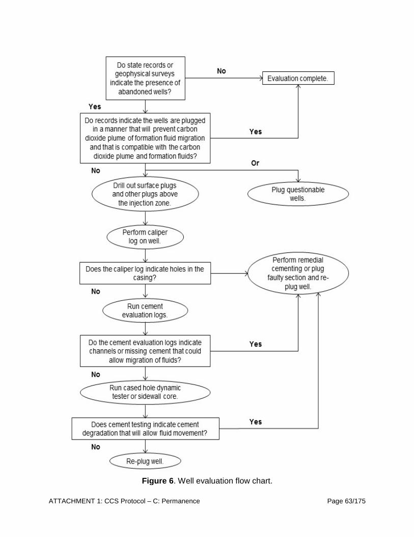
ATTACHMENT 1: CCS Protocol – C: Permanence Page 63/175
Figure 6. Well evaluation flow chart.

ATTACHMENT 1: CCS Protocol – C: Permanence Page 64/175
(d) Prior to CCS Project Certification, CCS Project Operators must perform
corrective action on all wells within the delineated AOR that require corrective action. In performing corrective action, CCS Project Operators must use methods designed to prevent the movement of fluid out of the storage complex into a shallower zone, including use of materials compatible with the CO2 stream, where appropriate.
(1) A well requires plugging if:
(A) Records indicate that a well plug sufficient to prevent upward movement of fluids does not exist at a depth corresponding to the primary confining layer, or there are no well plugs below permeable formations that may exhibit cross flow of mobilized fluids along the wellbore or casing; or
(B) Field evaluations reveal cracks, channels, or annuli in the plug that would allow fluid migration or suggest the plug material may corrode in response to reactions with CO2; or
(C) Field tests indicate the well is leaking gas or fluids.
(2) A well requires remedial cementing if records or field evaluations indicate that the cement surrounding the wellbore has failed or has cracks, channels, or annuli that could allow migration of CO2, or if the well has not been cemented.
(3) Materials used for cementing of abandoned wells must be supplemented with
or replaced by materials such as polymer gels and acrylic grouts, if required by the Executive Officer.
(e) If corrective action is warranted during the injection or post-injection period based on AOR reevaluation subsection C.2.4.4, the CCS Project Operator is required to take the following actions:
(1) Identify all wells or features within the AOR that require corrective action;
(2) Identify the appropriate corrective action the well or feature requires pursuant to subsection C.2.4.3;
(3) Prioritize corrective actions to be performed; and
(4) Conduct corrective actions under a schedule that minimizes risk to public health and the environment.
2.4.3.1. Casing Diagrams of Wells Penetrating the Primary Confining layer
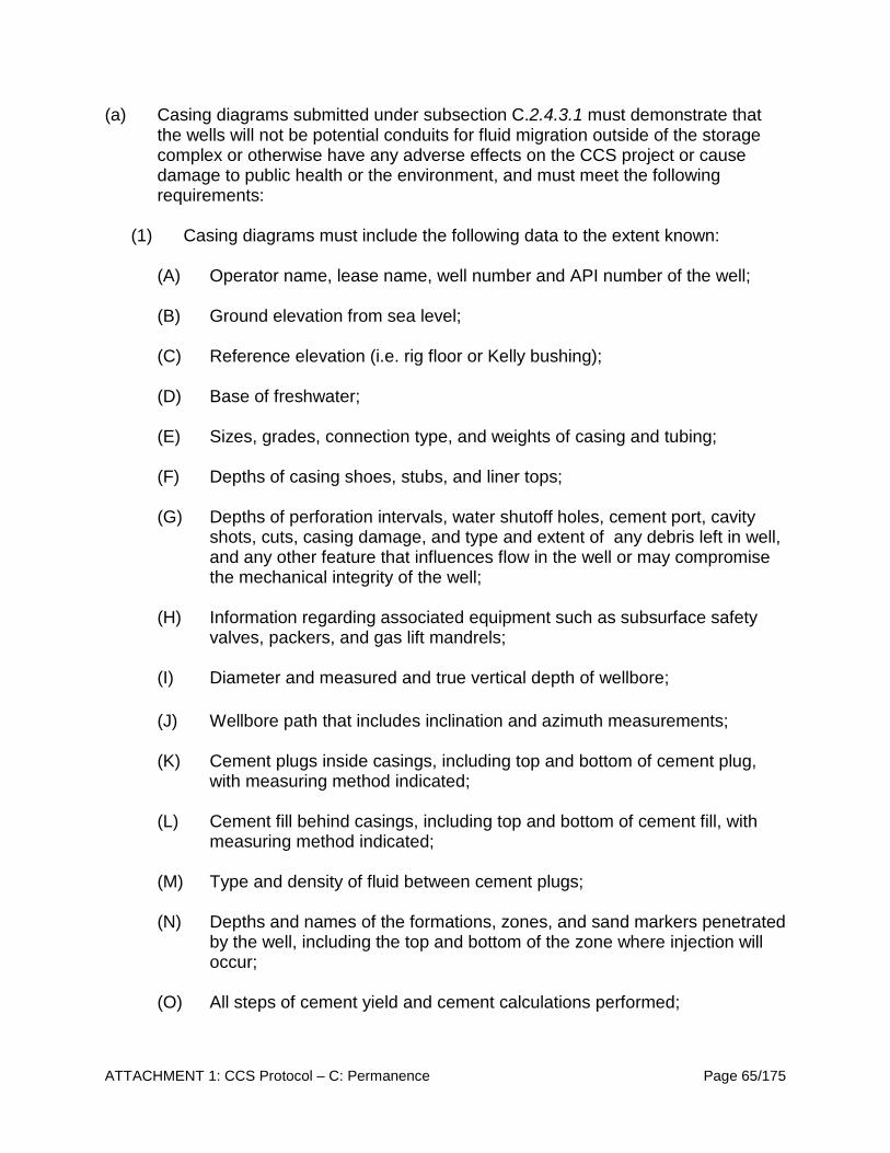
ATTACHMENT 1: CCS Protocol – C: Permanence Page 65/175
(a) Casing diagrams submitted under subsection C.2.4.3.1 must demonstrate that the wells will not be potential conduits for fluid migration outside of the storage complex or otherwise have any adverse effects on the CCS project or cause damage to public health or the environment, and must meet the following requirements:
(1) Casing diagrams must include the following data to the extent known:
(A) Operator name, lease name, well number and API number of the well;
(B) Ground elevation from sea level;
(C) Reference elevation (i.e. rig floor or Kelly bushing);
(D) Base of freshwater;
(E) Sizes, grades, connection type, and weights of casing and tubing;
(F) Depths of casing shoes, stubs, and liner tops;
(G) Depths of perforation intervals, water shutoff holes, cement port, cavity shots, cuts, casing damage, and type and extent of any debris left in well, and any other feature that influences flow in the well or may compromise the mechanical integrity of the well;
(H) Information regarding associated equipment such as subsurface safety valves, packers, and gas lift mandrels;
(I) Diameter and measured and true vertical depth of wellbore;
(J) Wellbore path that includes inclination and azimuth measurements;
(K) Cement plugs inside casings, including top and bottom of cement plug, with measuring method indicated;
(L) Cement fill behind casings, including top and bottom of cement fill, with measuring method indicated;
(M) Type and density of fluid between cement plugs;
(N) Depths and names of the formations, zones, and sand markers penetrated by the well, including the top and bottom of the zone where injection will occur;
(O) All steps of cement yield and cement calculations performed;
ATTACHMENT 1: CCS Protocol – C: Permanence Page 66/175
(P) All information used to calculate the cement slurry (volume, density, yield), including but not limited to, cement type and additives, for each cement job completed in each well; and
(Q) When multiple boreholes are drilled, all of the information listed in this section for the original hole and for any subsequent redrilled or sidetracked wellbores.
(2) Casing diagrams must be submitted as both a graphical diagram and as a flat file data set.
(3) Any additional information that the Executive Officer may require. 2.4.4. AOR Reevaluation (a) Every five years, or when monitoring and operational conditions warrant pursuant
to subsection C.2.4.4.1, CCS Project Operators must:
(1) Reevaluate the AOR in the manner specified in subsections C.2.4, C.2.4.1, and C.2.4.2;
(2) Modify model input parameters and calibrate the model by comparing historic data to recent observations of plume size based on operational and monitoring data collected in subsections C.3.2, C.3.3, and C.4.3;
(3) Identify all wells in the reevaluated AOR that require corrective action in the same manner specified in subsections C.2.4.2 and C.2.4.3;
(4) Perform corrective action on wells requiring corrective action in the reevaluated AOR in the same manner specified in subsections C.2.4.3 and C.2.4.3(d); and
(5) Submit either, an amended AOR and Corrective Action Plan including a description of the changes made to the model and a justification of those changes, or demonstrate to the Executive Officer through monitoring data and modeling results that no amendments to the AOR and Corrective Action Plan are needed. Any amendments to the AOR and Corrective Action Plan, or demonstrations of no changes to the AOR and Corrective Action Plan, must be approved by the Executive Officer, and must be incorporated into the Permanence Certification.
(b) The Emergency and Remedial Response Plan, Post-Injection Site Care and Closure Plan, and the demonstration of financial responsibility in subsection C.7 must account for the AOR delineated as specified in subsection C.2.4.2, or most recently evaluated AOR delineated under subsection C.2.4.4(a);
ATTACHMENT 1: CCS Protocol – C: Permanence Page 67/175
(c) AOR Reevaluation Requirements:
(1) Using newly collected and existing data, the CCS Project Operators must update and verify the site model and reevaluate the size and shape of the AOR as specified in the AOR and Corrective Action Plan. CCS Project Operators are required to take the following steps to evaluate CCS project data and, if necessary, reevaluate the AOR:
(1) Review monitoring data and compare it to the computational model predictions to assess whether the predicted CO2 plume migration is consistent with actual data;
(2) Review operating data to verify that it is consistent with the inputs used in the most recent modeling effort; and
(3) Review any new geologic data acquired since the last modeling effort and identify if any new data materially differ from modeling efforts.
(2) If the information reviewed is consistent with, or unchanged from, the most recent modeling assumptions or confirms modeled predictions about the maximum extent of free-phase plume and pressure front movement, the CCS Project Operator must prepare a report demonstrating that, based on the monitoring and operating data, no reevaluation of the AOR is needed. The report must include the data and results demonstrating that no changes are necessary;
(3) If material changes have occurred such that the actual CO2 free-phase plume or pressure front may extend beyond the area originally modeled, the CCS Project Operator must reevaluate the AOR, and the following steps must be taken:
(1) Revision of the site conceptual model based on new site characterization, operational, or monitoring data;
(2) Recalibration of the model to minimize the differences between monitoring data and model simulations; and
(3) Re-delineate the AOR as described in subsections C.2.4.2 and C.2.4.4.
(4) Review wells in any newly identified areas of the AOR and apply corrective action to deficient wells pursuant to subsection C.2.4.3;
(5) Following each evaluation, the CCS Project Operator must prepare and submit a report documenting the reevaluation process, including a description of the updated modeling effort, the data used for the reevaluation, any
ATTACHMENT 1: CCS Protocol – C: Permanence Page 68/175
corrective actions needed, and the schedule for any corrective actions to be performed; and
(6) Update the AOR and Corrective Action Plan to reflect the revised AOR, along with other related CCS project plans, as needed, and submit for approval by the Executive Officer.
(d) AOR Reevaluation Cycle:
(1) The CCS Project Operator must reevaluate the AOR at the minimum fixed frequency, not to exceed five years, as specified in the AOR and Corrective Action Plan, or when monitoring and operational conditions warrant, following subsection C.2.4.4(a);
(2) AOR reevaluations must be performed periodically during the post-injection phase following the Post-Injection Site Care and Site Closure Plan at subsection C.2. Post-injection pressure monitoring data must be compared to model pressure conditions predicted for the post-injection site care timeframe; and
(3) If monitoring or operational data suggest that a significant change in the size or shape of the actual CO2 plume as compared to the predicted CO2 plume and/or pressure front is occurring, or there are deviations from modeled predictions such that the actual plume or pressure front may extend vertically or horizontally beyond that modeled, the CCS Project Operator must initiate an AOR reevaluation prior to the next scheduled reevaluation pursuant to subsection C.2.4.4(a).
2.4.4.1. Triggers for AOR Reevaluations Prior to the Next Scheduled Reevaluation (a) Unscheduled reevaluations of the AOR must be based on observational or
quantitative changes of the monitoring parameters of the CCS project.
(b) Triggers for AOR reevaluations must be developed and quantified as part of the AOR evaluation pursuant to subsection C.2.4.2, based on site-specific risks identified in the Risk Assessment pursuant to subsection C.2.2.
(c) Observations that will trigger an AOR reevaluation include:
(1) Observed migration of the plume in any direction that is faster than that predicted by the model;
(2) Observed thickness of the CO2 plume that is much thinner than that predicted by the model;

ATTACHMENT 1: CCS Protocol – C: Permanence Page 69/175
(3) A trend in pressure increase at the injection well(s) or other monitoring points that deviates systematically from the predicted trend; and/or
(4) CO2 leakage charging a zone above the storage complex;
(d) An unscheduled AOR reevaluation may also be needed if it is likely that the actual free-phase CO2 plume or pressure front extend beyond that modeled because any of the following has occurred:
(1) An earthquake of magnitude 2.77 or greater within a one mile radius of the CCS project; or
(2) New site characterization data change the computational model to such an extent that the predicted free-phase CO2 plume or pressure front extends vertically or horizontally beyond the predicted AOR.
(e) Any site-specific criteria that will trigger an AOR reevaluation for a particular CCS project must be included in the AOR and Corrective Action Plan.
2.5. Baseline Monitoring (a) As part of the testing required to meet certification as described in subsection
C.4.1, CCS Project Operators must monitor the surface, near-surface, and deep subsurface for CO2 leakage that may endanger public health or the environment. The CCS Project Operator must submit a Baseline Testing Plan with the application for Sequestration Site Certification.
(b) The monitoring frequency and spatial distribution of surface, near-surface, and subsurface monitoring must be decided using site-specific criteria and according to a timeline and schedule set forth in the application for Sequestration Site Certification of no less than one year prior to the initiation of injection, or as required by the Executive Officer.
(c) Natural background variability in geochemical parameters should be characterized to define statistics for identifying CO2 leakage signals.
(d) Baseline data on CO2 concentrations and fluxes collected prior to operation must be used for history matching and comparison to levels during and after the operational phase of the CCS project to detect any CO2 leakage to the deep subsurface, shallow subsurface, and surface or atmosphere.
(e) Any properties of the AOR that may affect baseline data must be evaluated, including but not limited to: downhole pressure, sequestration zone fluid
7 Cal. Code Regs., tit. 14, § 1724.14, “Pre-Rulemaking Discussion Draft 04-26-17 Updated Underground Injection Control Regulations,” (2017).
ATTACHMENT 1: CCS Protocol – C: Permanence Page 70/175
chemistry, surface soil type, soil organic carbon content, vegetation type and density, topography, and surface water hydrology.
(f) Data collection and analyses:
(1) The determination of the baseline monitoring strategy must be determined on a site-specific basis following the risk assessment pursuant to subsection C.2.2 and computational modeling results pursuant to subsection C.2.4.1.
(2) For soil and air sampling, the spatial distribution of soil CO2 fluxes and concentrations must be determined on a site-specific basis, but requires, at a minimum, repeat measurements at several fixed sites, and over a period of one year, to capture any seasonal or diurnal variations. CCS Project Operators must plan the location of soil gas and surface air sampling points based on the following considerations:
(A) Avoid areas with highly fluctuating background concentrations, based on
previously recorded data;
(B) Target potential point sources, including wellheads, artificial penetrations, and fault or fracture zones. A transect-profiling approach may be used for linear features, such as faults;8 and
(C) A grid methodology, must be used when monitoring soil for non-point
source leakage throughout the AOR. Grid cell spacing may range over several orders of magnitude, depending on site-specific factors.
(g) Baseline monitoring report:
(1) The CCS Project Operator must submit a descriptive report of baseline
monitoring data and interpretations with the application for CCS Project Certification. The report must include surface air or soil gas analyses, and CCS Project Operators must submit, at a minimum, the following:
(A) Site characteristics (e.g. soil type, soil organic carbon content, vegetation
type and density, topography, surface water hydrology);
(B) Sampling locations (in map form) and dates sampled;
(C) Atmospheric conditions;
(D) Sampling and analytical methods, including detection limits;
8 ASTM International (ASTM), “Standard Guide for Soil and Gas Monitoring in the Vadose Zone,” ASTM D5314 - 092 (2001), DOI: 10.1520/D5314-92R06. http://www.astm.org.

ATTACHMENT 1: CCS Protocol – C: Permanence Page 71/175
(E) Results presented as concentrations and fluxes in tabular and graphic form, including quality assurance (QA) samples and analyses;
(F) Methods and results of regression analyses; and
(G) Methods and results of any ecological modeling or sensitivity analysis performed, including input data and outputs.
(h) The CCS Project Operator must demonstrate that the locations sampled
represent a reasonable grid size and that potential point sources are represented and will serve as a good baseline to compare to future monitoring data. The CCS Project Operator must also demonstrate that seasonal and diurnal variations in CO2 levels have been captured and describe the variability in the data for future reference. If an inadequate time series of analyses was performed or if there are concerns regarding the quality of analytical data, the CCS Project Operator may need to collect and submit additional data.
3. Well Construction and Operating Requirements 3.1. Well Construction (a) General Requirements:
(1) The CCS Project Operator must ensure that all injection, observation or
monitoring, and production wells associated with the CCS project are constructed and completed to:
(A) Prevent the movement of fluids into or between any unauthorized zones; (B) Permit the use of appropriate testing devices and workover tools; and (C) Permit continuous monitoring of the pressure in the annulus space
between the injection tubing and long string casing.
(b) The CCS Project Operator is required to submit a Well Construction Plan with the application for Sequestration Site Certification, pursuant to subsection C.1.1.2.
(c) Casing and cementing of CCS project wells:
(1) Casing and cement or other materials used in the construction of each well associated with a certified CCS project must have sufficient structural strength and be designed for the life of the CCS project. All well materials must be compatible with fluids with which the materials may be expected to come into contact and must meet or exceed standards developed for such materials by API, ASTM International, or comparable standards acceptable to

ATTACHMENT 1: CCS Protocol – C: Permanence Page 72/175
the Executive Officer. The casing and cementing program must be designed to prevent the movement of fluids out of the sequestration zone and above the storage complex. In determining and specifying the casing and cementing requirements, the CCS Project Operator must consider the following factors:
(A) Depth to the sequestration zone;
(B) Injection pressure, external pressure, internal pressure, and axial loading;
(C) Hole size;
(D) Size and grade of all casing strings (wall thickness, external diameter, nominal weight, length, joint specification, and construction material);
(E) Corrosiveness of the CO2 stream and formation fluids;
(F) Downhole temperatures;
(G) Lithology of sequestration and confining layer;
(H) Type or grade of cement and cement additives; and
(I) Quantity, chemical composition, and temperature of the CO2 stream.
(2) Surface casing must extend through the base of the lowermost freshwater aquifer and be cemented to the surface through the use of a single or multiple strings of casing and cement.
(3) At least one long string casing, using a sufficient number of centralizers, must extend to the sequestration zone and must be cemented by circulating cement to the surface in one or more stages. The CCS Project Operator may use an alternate method of cementing if cementing to surface will compromise the integrity of the well or confining layer, provided the operator:
(A) Submits a demonstration as part of the Well Construction Plan describing the proposed method of cementing and an explanation for why the particular method was chosen;
(B) Follows best practices that meet or exceed standards developed for such methods and materials by API, ASTM International, or comparable standards acceptable to the Executive Officer; and
(C) Receives Executive Officer approval prior to well construction.
ATTACHMENT 1: CCS Protocol – C: Permanence Page 73/175
(4) Cement and cement additives must be of sufficient quality and quantity to maintain integrity over the design-life of the CCS project. The integrity and location of the cement must be verified using technology capable of (1) evaluating cement quality radially and (2) identifying the location of channels to ensure the likelihood of an unintended release of CO2 from the sequestration zone above the storage complex is not likely.
(5) Cement and cement additives must be compatible with the CO2 stream and formation fluids within the sequestration zone.
(6) Any changes to casing and/or cement materials or designs that deviate from the casing and cementing program in the initial Sequestration Site Certification application must be submitted and approved by the Executive Officer before CCS Project Certification is granted.
(d) Tubing and packer:
(1) Tubing and packer materials used in the construction of each well associated with the CCS project must be compatible with fluids with which the materials may be expected to come into contact and must meet or exceed standards developed for such materials by API, ASTM International, or comparable standards acceptable to the Executive Officer.
(2) CCS Project Operators of must inject fluids through tubing with a packer set within the long string casing at a point within or below the primary confining layer, or at an interval at a location approved by the Executive Officer.
(3) In determining and specifying the tubing and packer requirements, the CCS Project Operator must consider the following factors:
(A) Depth of setting;
(B) Characteristics of the CO2 stream (chemical content, corrosiveness, temperature, and density) and formation fluids;
(C) Maximum proposed injection pressure;
(D) Maximum proposed annular pressure;
(E) Proposed injection rate (intermittent or continuous) and volume and/or mass of the CO2 stream;
(F) Size of tubing and casing; and
(G) Tubing tensile strength, burst, and collapse pressures.

ATTACHMENT 1: CCS Protocol – C: Permanence Page 74/175
(4) Any change to the tubing and packer used in the well that deviates from those proposed in initial CCS project application for CCS Project Certification must be submitted and approved by the Executive Officer before CCS Project Certification is granted.
(e) Wellheads and Valves:
(1) The CCS Project Operator must equip all wells associated with the CCS project with wellheads, valves, piping, and surface facilities that meet or exceed design standards developed for such materials by API, ASTM International, or comparable standards acceptable to the Executive Officer.
(2) All piping, valves, and facilities must meet or exceed design standards for the maximum anticipated allowable injection pressure, and must be maintained in a safe and leak-free condition.
(3) The CCS Project Operator must equip all ports on the wellhead assembly above the casing bowl of injection wells with valves, blind flanges, or similar equipment.
(4) The CCS Project Operator must equip wells with valves to provide isolation of the wells from the pipeline system and to allow for entry into the wells.
(f) Routine well maintenance:
(1) Routine well maintenance must be conducted at a minimum of every six months. Routine maintenance consists of wellhead valve maintenance and measurement of casing annular pressures. If a significant deviation such that the mechanical integrity of the well is compromised or may become compromised, the appropriate remediation plan must be triggered.
3.2. Pre-Injection Testing (a) During the drilling and construction of wells for the CCS project, the CCS Project
Operator must run appropriate logs, surveys, and tests to: (1) determine or verify the depth, thickness, porosity, permeability, and lithology of the sequestration zone, (2) measure the salinity and TDS of any formation fluids in all relevant geologic formations, (3) ensure conformance with the well construction requirements under subsection C.3.1, and (4) establish accurate baseline data against which future measurements will be compared.
(b) The CCS Project Operator is required to submit a Pre-Injection Testing Plan with the application for Sequestration Site Certification, pursuant to subsection C.1.1.2.
ATTACHMENT 1: CCS Protocol – C: Permanence Page 75/175
(c) The CCS Project Operator must submit, with the application for CCS Project Certification, a descriptive report that includes an interpretation of the results of such logs and tests. At a minimum, such logs and tests must include:
(1) Deviation checks during drilling on all holes constructed by drilling a pilot hole that is enlarged by reaming or another method. Such checks must be at sufficiently frequent intervals to determine the location of the borehole and to ensure that vertical avenues for fluid movement in the form of diverging holes are not created during drilling; and
(2) A series of tests before and upon installation of the surface casing, and before and upon installation of the long string casing:
(A) A series of tests to evaluate the geological and hydrological characteristics
of the wellbore following procedures outlined in subsection C.2.3.1; and
(B) Casing inspection logs to evaluate the integrity of the cement bond, such as variable density, temperature, and acoustic logs, or an alternative method approved by the Executive Officer, after the casing is set and cemented.
(3) A series of tests designed to demonstrate the internal and external mechanical integrity of injection wells, which must include:
(A) An annulus pressure test or a radioactive tracer survey, pursuant to subsection C.4.2(b)(1) and C.4.2(b)(3);
(B) A temperature, noise, or oxygen activation log, or a radioactive tracer survey; and
(C) A casing inspection log pursuant to subsection C.4.3.1.4.
(4) Any alternative methods that provide equivalent or better information and that are required or approved by the Executive Officer.
(d) The CCS Project Operator must record the fluid temperature, pH, conductivity, reservoir pressure, and static fluid level of the sequestration zone.
(e) At a minimum, the CCS Project Operator must determine or calculate the following information concerning the sequestration zone and confining layer pursuant to subsection C.2.3(c):
(1) Fracture pressure;
(2) Other physical and chemical characteristics of the sequestration zone and confining layer; and

ATTACHMENT 1: CCS Protocol – C: Permanence Page 76/175
(3) Physical and chemical characteristics of the formation fluids in the
sequestration zone.
(f) Upon completion, but prior to operation, the CCS Project Operator must conduct tests to verify hydrogeologic characteristics of the sequestration zone pursuant to subsection C.2.3(c), including a pressure fall-off test and a pump test or injectivity tests.
(g) The CCS Project Operator must provide the Executive Officer with the opportunity to witness all logging and testing conducted in accordance with this section. A state licensed engineer, or equivalent, may be allowed to witness logging and testing, if approved by the Executive Officer.
3.3. Injection Well Operating Requirements (a) The CCS Project Operator is required to submit a Well Operating Plan with the
application for Sequestration Site Certification, pursuant to subsection C.1.1.2. This operating plan must include: (1) A map showing the injection facilities;
(2) Maximum anticipated surface injection pressure (pump pressure) and
daily rate of injection, by well;
(3) Monitoring schedule and system or method to be utilized to ensure that no damage is occurring to the well or associated surface facilities and that all injection fluid is confined to the sequestration zone;
(4) Method of injection; and
(5) Treatment of water injected during water alternating gas (WAG) methods are used for CO2-EOR purposes;
(b) The CCS Project Operator must ensure that injection pressure does not exceed
80 percent of the fracture/parting pressure of the sequestration zone so as to ensure that injection does not initiate or propagate existing fractures in the sequestration zone. In no case may injection pressure initiate fractures in the confining layer, or cause movement of the injection or formation fluids out of authorized zones.
(c) Injection between the outermost casing and the wellbore is prohibited. The space between the casing and the formation is to be cemented following subsection C.3.1(c)(3).

ATTACHMENT 1: CCS Protocol – C: Permanence Page 77/175
(d) The CCS Project Operator must fill the annulus between the tubing and the long string casing with a non-corrosive fluid (e.g., a brine containing a corrosion inhibitor).
(e) Other than during periods of well workover approved by the Executive Officer in which the annulus between the tubing and long string casing is disassembled for maintenance or corrective procedures, the CCS Project Operator must monitor and maintain mechanical integrity in all wells associated with the CCS project at all times.
(f) If a shutdown (either downhole or at the surface) is triggered or a loss of
mechanical integrity is discovered, the CCS Project Operator must immediately investigate and identify as expeditiously as possible the cause of the shutdown. If, upon such investigation, the well appears to be lacking mechanical integrity, or if monitoring required under subsection C.3.3(f) of this section otherwise indicates that the well may be lacking mechanical integrity, the CCS Project Operator must:
(1) Immediately cease injection, otherwise, all credits generated are subject to invalidation;
(2) Take all steps reasonably necessary to determine whether there may have been a release of the injected CO2 stream or formation fluids into any unauthorized zone;
(3) Notify the Executive Officer in writing within 24 hours;
(4) Restore and demonstrate mechanical integrity prior to resuming injection; and
(5) Notify the Executive Officer when injection can be expected to resume. 3.4. Operating Restrictions and Incident Response (a) In order to receive credit, the CCS Project Operator must cease injection into the
affected injection well and must not resume injection into the well without subsequent approval from the Executive Officer if any of the following occurs:
(1) The CCS Project Operator has not performed mechanical integrity testing on the well as required by subsection C.4.2 or the notification and results required under subsection C.4.2.1 have not been provided to the Executive Officer;
(2) The well failed a mechanical integrity test required by subsection C.4.2, or there is any other indication that the well lacks mechanical integrity or is otherwise incapable of performing as approved by the Executive Officer;

ATTACHMENT 1: CCS Protocol – C: Permanence Page 78/175
(3) An automatic alarm or automatic shut-off system is triggered;
(4) The well experiences a significant, unexpected change in pressure in the annulus between the tubing and the long string casing, or injection pressure;
(5) There is any indication of a failure, breach, or hole in the well tubing, packer or well casing, including failures above or below a packer;
(6) There is any indication that fluids being injected into the well are not confined to the intended zone of sequestration;
(7) There is any indication that damage to public health, the environment, natural resources, or loss of hydrocarbons is occurring by reason of the injection; or
(8) Any non-compliance with any certification condition or local regulatory requirement is discovered and the Executive Officer determines that the injection must cease.
(b) The CCS Project Operator must immediately notify the Executive Officer upon ceasing injection operations by reason of subsection C.3.4(a), indicating the affected well and the specific reason for ceasing injection.
(c) The CCS Project Operator must comply with all operational and remedial directives of the Executive Officer related to the reason for ceasing injection.
4. Injection Monitoring Requirements 4.1. Testing and Monitoring (a) Testing and Monitoring Plan. The CCS Project Operator must prepare, maintain,
and comply with a testing and monitoring plan to ensure that the CCS project is operating as certified and that the CO2 injected is permanently sequestered. The Testing and Monitoring Plan must be submitted with the application for Sequestration Site Certification, and must include a description of how the CCS Project Operator will meet the testing and monitoring requirements, including accessing sites for all necessary monitoring and testing during the active life of the CCS project and the post-injection site care period. Testing and monitoring associated with CCS projects must include:
(1) Analysis of the CO2 stream with sufficient frequency to yield data representative of its chemical and physical characteristics pursuant to subsection C.4.3.1.1;
(2) Installation and use, except during well workovers, of continuous recording devices to monitor: (1) injection rate and volume pursuant to
ATTACHMENT 1: CCS Protocol – C: Permanence Page 79/175
subsection C.4.3.1.2, (2) injection pressure and the pressure on the annulus between the tubing and the long string casing pursuant to subsection C.4.3.1.3, and (3) the annulus fluid volume added;
(3) Corrosion monitoring of well materials, upon well completion and a minimum of once per every five years thereafter, for loss of mass, thickness, cracking, pitting, and other signs of corrosion, to ensure that well components meet the minimum standards for material strength and performance set by API, ASTM International, or equivalent, by:
(A) Analyzing corrosion coupons of the well construction materials placed in contact with the CO2 stream; or
(B) Routing the CO2 stream through a loop constructed with the material used in the well and inspecting materials in the loop;
(C) Performing casing inspection logs; or
(D) Using an alternative method approved by the Executive Officer.
(4) Periodic monitoring of pressure and/or composition above the storage complex. In sites where it is feasible and useful, groundwater quality and geochemistry must be considered. The rationale and leakage detection threshold of the selected monitoring method must be demonstrated;
(5) The location and number of monitoring wells based on specific information about the CCS project, including injection rate and volume, geology, the presence of artificial penetrations and other factors;
(6) The monitoring frequency and spatial distribution of monitoring wells based
on any modeling results required by subsection C.2.4.1;
(7) A demonstration of external mechanical integrity pursuant to subsection C.4.2 at least once per year until the injection well is plugged, and, if required by the Executive Officer, a casing inspection log pursuant to requirements at subsection C.4.2(c) at a frequency established in the Testing and Monitoring Plan;
(8) A pressure fall-off test at least once every five years, pursuant to subsection C.4.3.1.5, unless more frequent testing is required by the Executive Officer based on site-specific information;
(9) Testing and monitoring to track the extent of the CO2 plume, and the presence or absence of elevated pressure;
ATTACHMENT 1: CCS Protocol – C: Permanence Page 80/175
(10) Surface air monitoring and soil gas monitoring to detect potential movement of CO2 in the shallow subsurface or atmosphere;
(11) At a minimum, the monitoring plan must stipulate and include:
(A) The frequency of data acquisition;
(B) A record keeping plan;
(C) The frequency of instrument calibration activities;
(D) The QA/QC provisions on data acquisition, management, and record keeping that ensures it is carried out consistently and with precision;
(E) The role of individuals performing each specific monitoring activity; and
(F) Methods to measure and quantify the following data:
1. Quantity of CO2 emitted from the capture site;
2. Quantity of CO2 sold to third parties (e.g., for enhanced oil recovery) including sufficient measurements to support data required; and
3. Quantity of CO2 injected into each well in the CCS project, metered at the wellhead.
(12) Any additional monitoring, as required by the Executive Officer, necessary to
support, upgrade, and improve computational modeling of the AOR evaluation required under subsection C.2.4.1;
(13) The CCS Project Operator must periodically review the Testing and Monitoring Plan to incorporate monitoring data collected under this subsection, operational data collected under subsection C.3, and the most recent AOR reevaluation performed under subsection C.2.4.4; and
(14) The CCS Project Operator must review the Testing and Monitoring Plan no less than once every five years. Based on this review, the CCS Project Operator must submit an amended Testing and Monitoring Plan or demonstrate to the Executive Officer that no amendment to the Testing and Monitoring Plan is needed. Any amendments to the Testing and Monitoring Plan must be approved by the Executive Officer. Amended plans or demonstrations must be submitted to the Executive Officer as follows:
(A) Within one year of an AOR reevaluation; or
(B) When required by the Executive Officer.

ATTACHMENT 1: CCS Protocol – C: Permanence Page 81/175
4.2. Mechanical Integrity Testing (a) Any well that is part of a CCS project must have and maintain mechanical
integrity at all times during operation, other than during periods of well workover for maintenance or corrective action. A well has mechanical integrity if:
(1) There is no internal leak in the casing, tubing, or packer;
(2) There is no significant external fluid movement out of the sequestration zone through channels adjacent to the wellbore; and
(3) Corrosion monitoring, pursuant to subsection C.4.3.1.4, reveals no loss of mass or thickness that may indicate the deterioration of well components (casing, tubing, or packer).
(b) The CCS Project Operator must conduct mechanical integrity testing as follows:
(1) Internal mechanical integrity must be demonstrated prior to commencing injection operations. Thereafter, the internal mechanical integrity of each well must be tested at least once every five years, after every workover (see subsection C.4.2(c)(6), below), or at the request of the Executive Officer. CCS Project Operator must submit a descriptive report of the internal mechanical integrity test results with the application for CCS Project Certification.
(2) External mechanical integrity must be demonstrated within three months after injection has commenced. Thereafter, wells must be tested at least once each year, or on a testing schedule approved by the Executive Officer.
(3) The CCS Project Operator must demonstrate internal mechanical integrity and test for possible leaks in the casing, tubing, or packer, under subsection C.4.2(b)(1), via:
(A) An annulus pressure test;
(B) A radioactive tracer survey; or
(C) An alternative test approved by the Executive Officer.
(4) The CCS Project Operator must demonstrate external mechanical integrity and test for possible leaks from channels adjacent to the wellbore under subsection C.4.2(b)(2), via:
(A) A temperature log;

ATTACHMENT 1: CCS Protocol – C: Permanence Page 82/175
(B) A noise log;
(C) An oxygen activation log;
(D) A radioactive tracer survey; or
(E) An alternative test approved by the Executive Officer.
(5) The well must pass a suitable annulus pressure test to demonstrate mechanical integrity after any workover that has the potential to compromise the internal mechanical integrity of the well, including but not limited to the downhole replacement of tubing, safety valves, and/or electrical submersible pumps.
(6) The CCS Project Operator must demonstrate external mechanical integrity prior to plugging the well following the requirements of this subsection and subsection C.5.1.
(c) Following the initial annulus pressure test, the CCS Project Operator must continuously monitor pressure on the annulus between the tubing and long string casing, except during well workovers. Continuous monitoring of the pressure on the annulus must be used to verify internal mechanical integrity during the injection phase of the project, and must be performed in concert with continuous monitoring of injection pressure, rate, and annulus fluid volume pursuant to subsections C.4.3.1.1, C.4.3.1.2, and C.4.3.1.3.
(d) In conducting and evaluating the tests listed in this section or others to be allowed by the Executive Officer, the CCS Project Operator must apply methods and standards generally accepted in the industry. When the CCS Project Operator reports the results of mechanical integrity tests to the Executive Officer, he/she must include a description of the tests and a justification for the methods used.
(e) Prior notice and reporting.
(1) The CCS Project Operator must notify the Executive Officer of his or her intent to demonstrate mechanical integrity at least 30 days prior to such demonstration. At the discretion of the Executive Officer, a shorter time period may be allowed.
(2) Reports of mechanical integrity demonstrations that include logs must include an interpretation of results by an experienced log analyst. The CCS Project Operator must report the results of a mechanical integrity demonstration within the time period specified in subsection C.1.1.3.
ATTACHMENT 1: CCS Protocol – C: Permanence Page 83/175
(f) Gauge and meter calibration: The CCS Project Operator must calibrate all gauges used in mechanical integrity demonstrations and other required monitoring to an accuracy of not less than five percent of full scale, within one year prior to each required test. The date of the most recent calibration must be noted on or near the gauge or meter. A copy of the calibration certificate must be submitted to the Executive Officer with the report of the test. Pressure gauge resolution must be no greater than five psi. Certain mechanical integrity and other testing may require greater accuracy and must be identified in the procedure submitted to the Executive Officer prior to the test.
4.2.1. Reporting of Mechanical Integrity Tests a) The CCS Project Operator must submit a descriptive report prepared by an
experienced log analyst that includes the results of any mechanical integrity test with the application for CCS Project Certification, and annually, thereafter through the active life of the CCS Project. At a minimum, the report must include:
(1) Chart and tabular results of each log or test;
(2) The interpretation of log results provided by the log analyst;
(3) A description of all tests and methods used;
(4) The records and schematics of all instrumentation used for the tests and the most recent calibration of any instrumentation;
(5) The identification of any loss of mechanical integrity, evidence of fluid leakage, and remedial action taken;
(6) The date and time of each test;
(7) The name of the logging company and log analyst;
(8) For any tests conducted during injection, operating conditions during measurement, including injection rate, pressure, and temperature (for tests run during well shut-in, this information must be provided relevant to the period prior to shut-in); and
(9) For any tests conducted during shut-in, the date and time of the completion of injection and records of well stabilization.
4.2.2. Loss of Mechanical Integrity (a) If the CCS Project Operator or the Executive Officer finds that a well (1) fails to
demonstrate mechanical integrity during a test, (2) fails to maintain mechanical
ATTACHMENT 1: CCS Protocol – C: Permanence Page 84/175
integrity during operation, or (3) that a loss of mechanical integrity is suspected during operation, the CCS Project Operator must:
(1) Take all steps reasonably necessary to determine whether there may have
been a release of the injected CO2 stream or formation fluids into any unauthorized zone. If there is evidence of substantial endangerment to public health or the environment from any fluid movement out of the intended storage complex, implement the Emergency and Remedial Response Plan, as described in subsection C.6;
(2) Follow the reporting requirements as directed in subsection C.1.1.3; and
(3) Restore and demonstrate mechanical integrity prior to resuming injection or plugging the well.
(b) If the well loses mechanical integrity prior to the next scheduled test date, then the well must be repaired and retested within 30 days of losing mechanical integrity.
(c) If the well lost mechanical integrity prior to the next scheduled test date, and it was repaired, the CCS Project Operator must submit a descriptive report documenting the type of failure, the cause, the required repairs, and a new test of mechanical integrity following the requirements of subsection C.4.2 in the next quarterly report.
4.3. CCS Project Monitoring (a) Monitoring requirements for CCS projects are addressed in two separate
categories: CCS project emissions monitoring, and the monitoring, measurement, and verification of containment. The first includes quantification and measurement activities required to quantify the net GHG reductions from the CCS project. The second category is for monitoring, measurement, and verification activities that are required to ensure that the CO2 injected is permanently contained with the storage complex.
(b) The CCS Project Operator must install and use:
(1) Continuous recording devices to monitor: the injection pressure, the rate, volume and/or mass, and temperature of the CO2 stream, and the pressure on the annulus between the tubing and the long string casing and annulus fluid volume; and
(2) Alarms and automatic surface shut-off systems (e.g., automatic shut-off, check valves) for wells, or other mechanical devices that provide equivalent protection.

ATTACHMENT 1: CCS Protocol – C: Permanence Page 85/175
(c) The CCS Project Operator must retain all records and all monitoring information, including all calibration and maintenance records and all original chart recordings for continuous monitoring instrumentation and copies of all reports, for emissions and containment monitoring for a period of 10 years after site closure.
4.3.1. CCS Project Emissions Monitoring (a) Emissions monitoring requirements include measurements of relevant
parameters to account for all supplemental energy inputs (e.g., fossil fuels and electricity) required for the operation of the CCS project. Data capture must be sufficient to ensure that the quantification and documentation of CO2 sequestered is replicable and verifiable pursuant to the Accounting Requirements in section B.
(b) CCS project monitoring techniques must use metering equipment such as gas flow meters, utility meters (gas and electricity) and gas analyzers. Meters must be maintained to operate consistent with design specifications and must be calibrated on a regular basis.
(c) Data quality management must include sufficient data capture to support quantification and verification of CO2 sequestered. Any assumptions and contingency procedures must be documented. Any monitoring plan and implementation must take into account the location, type of equipment, and frequency by which each variable is measured.
4.3.1.1. Analysis of the CO2 Stream (a) The CCS Project Operator must sample and analyze the CO2 stream at a
frequency sufficient to yield data representative of the chemical and physical characteristics of the injectate (i.e., at least once every quarter), whenever the result may deviate from the original certified specifications, and as requested by the Executive Officer.
(b) Analysis of the CO2 stream must be reported quarterly, pursuant to subsection C.1.1.3. The report must include characteristics such as fluid composition (i.e., fraction of CO2 and other constituents measured on a volumetric or mass basis at a known temperature and pressure), temperature, pressure, and any other parameters needed to identify potential interactions between the injectate and the formation or well materials. The CCS Project Operator must justify that the samples are representative of the fluid streams and suitable for use in accounting and fluid-flow modeling. The CCS Project Operator must submit, at a minimum, the following:
(1) A list of chemicals analyzed, including CO2 and other constituents (e.g., sulfur dioxide, hydrogen sulfide, nitrogen oxides);
ATTACHMENT 1: CCS Protocol – C: Permanence Page 86/175
(2) A description of the sampling methodology, noting any differences from those listed in the Testing and Monitoring Plan and an explanation of why a different method was used;
(3) Any laboratory analytical methods used, the name of the laboratory performing the analysis, and official laboratory analytical reports including sample chain-of-custody forms;
(4) All sample dates and times;
(5) A tabulation of all available carbon dioxide stream analyses, including QA/QC samples;
(6) Interpretation of the results with respect to regulatory requirements and past results;
(7) Identification and explanation of data gaps, if any; and
(8) Any identified necessary changes to the CCS project Testing and Monitoring Plan.
(c) The report must include a determination that any potential chemical reactions between the injectate and the formation or well materials are minimal and will not significantly affect the integrity of the well or the injectivity of the formation.
(d) The report must include a determination that the injectate does not meet the qualifications of hazardous waste under the RCRA, 42 U.S.C. 6901 et seq. (1976), and/or CERCLA, 42 U.S.C. 9601 et seq. (1980).
(e) Injectate fluid samples must be collected from a point immediately upstream or downstream of the flow meter.
4.3.1.2. Continuous Monitoring of Injection Rate and Volume (a) The CCS Project Operator must continuously monitor the injection rate and
volume for each CCS injection well.
(b) Flow rate data must be used (1) to determine the cumulative volume of CO2 injected, and (2) to verify compliance with the operational conditions of the Permanence Certification.
(c) Monitoring requirements must include measurements of relevant parameters to account for the flow rate of injected fluids, the concentration of the fluid stream, and the energy inputs required for operation.
ATTACHMENT 1: CCS Protocol – C: Permanence Page 87/175
(d) CCS Project Operators are required to perform the following measurements and monitoring for injected fluids:
(1) Flow rate of injection stream:
(A) Continuous measurement of the gas flow rate, gas composition, and gas density, where continuous measurement is defined as a minimum of one measurement every 15 minutes;
(B) Meter readings need to be temperature and pressure compensated such that the meter output is set to standard reference temperatures and pressures;
(C) Estimates of composition and density are not permissible;
(D) Flow meters must be located immediately upstream the gas injection process, such that they are downstream of all capture, compression, and transport to account for any fugitive losses or venting. Flow meters must be placed based on manufacturer recommendations;
(E) Flow meters must be calibrated according to manufacturer specifications. Meters must be checked/calibrated at regular intervals according to these specifications and industry standards; and
(F) Ownership transfer must be clearly documented for CO2 transferred (third-party injection activity).
(2) Concentration of injection stream:
(A) Continuous measurement of the fluid composition and density where continuous measurement is defined as a minimum of one measurement every 15 minutes; and
(B) The fluid composition must be metered downstream of the capture and processing equipment while the volume is measured immediately upstream the point where CO2 is injected into the well.
(e) Injection rate and volume data must be submitted in the quarterly reports pursuant to subsection C.1.1.3. The report must include, at a minimum:
(1) Tabular data of all flow rate measurements and a description of interpretation
of the data aided with charts or graphs;
(2) A description of the measuring methodology and technology, noting any differences from those given in the Testing and Monitoring Plan and an explanation of why a different methodology was used;
ATTACHMENT 1: CCS Protocol – C: Permanence Page 88/175
(3) The monthly average flow rate;
(4) The monthly maximum and minimum values;
(5) The total volume (mass) injected each month;
(6) The cumulative volume (mass) calculated for the CCS project;
(7) If flow rate exceeded certified operational limits during the reporting period, an
explanation of the event(s), including the cause of the excursion, the length of the excursion, and response to the excursion;
(8) Identification and explanation of data gaps, if any; and
(9) Any identified necessary changes to the CCS project Testing and Monitoring Plan and the justification for those changes.
4.3.1.3. Continuous Monitoring of Injection Pressure (a) During operation, the CCS Project Operator must continuously monitor injection
pressure, at the wellhead (i.e., wellhead pressure) and downhole (i.e., bottom-hole pressure).
(b) Injection pressure is monitored to ensure that the fracture pressure of the sequestration zone and the burst pressure of the well tubing are not exceeded and that the owner or CCS Project Operator is in compliance with certified operating conditions.
(c) The CCS Project Operator must insure that the injection pressure remains at or below 80 percent of the fracture pressure of the sequestration zone.
(d) During injection, pressure in the annular space directly above the packer must be maintained at least 100 to 200 psi9 higher than the tubing pressure.
(e) Maximum allowable surface pressure must equal top perforation depth, in true vertical depth, multiplied by the difference between the injection gradient and the injectate fluid gradient.
(f) Significant changes of the pressure in the annulus between the tubing and the long string casing during injection may indicate a loss of internal mechanical integrity. If pressure monitoring indicates that the well is experiencing a loss of mechanical integrity, the CCS Project Operator must follow the procedures outlined in subsection C.4.2.2.
9 U.S. EPA Region 8, Groundwater Section Guidance Number 39, (1995; updated 2006), Denver, CO.
ATTACHMENT 1: CCS Protocol – C: Permanence Page 89/175
(g) Pressure data must be reported in the annual reports following subsection C.1.1.3. The CCS Project Operator must submit, at a minimum, the following:
(1) Tabular data of all pressure measurements, a description and interpretation of the data aided with charts or graphs, and gauge calibration records;
(2) A description of the measurement methodology, noting any differences from what was established in the Testing and Monitoring Plan, and a justification of why a different methodology was used;
(3) Corrections made due to the impacts of fluctuating injectate temperature;
(4) The monthly average value for injection pressure;
(5) The monthly maximum and minimum values for injection pressure;
(6) If pressure exceeded permit limits during the reporting period, an explanation of the event(s), including the cause of the exceedance, the length of the excursion, and response to the excursion;
(7) Identification and explanation of data gaps, if any; and
(8) Any identified necessary changes to the CCS project Testing and Monitoring Plan to ensure continued protection of public health and the environment, including any changes in the data measurement or averaging methods.
4.3.1.4. Corrosion Monitoring and Casing Inspection (a) CCS Project Operators must monitor well materials for corrosion at a frequency
specified in the Testing and Monitoring Plan following subsection C.4.1, not to exceed once every five years.
(b) Well components must be monitored for corrosion using at least one of the following methods:
a. Corrosion coupons or loops;
b. Casing inspection logs (CILs), such as caliper, electromagnetic phase-shift, electromagnetic flux test log, or ultrasonic test logs; or
c. An alternative method approved by the Executive Officer.
(c) Well corrosion monitoring data must be reported annually to CARB including, at a minimum, the following:

ATTACHMENT 1: CCS Protocol – C: Permanence Page 90/175
(1) A description of the techniques used for corrosion monitoring;
(2) Measurement of (mass and thickness/weight) loss from any corrosion coupons or loops used;
(3) Assessment of additional corrosion, including pitting, in any corrosion coupons or loops;
(4) Measurement of thickness loss or corrosion detected in any CILs;
(5) All measured CILs and comparison to previous logs;
(6) Identification and explanation of data gaps, if any; and
(7) Any identified necessary changes to the CCS project Testing and Monitoring Plan.
4.3.1.5. Pressure Fall-Off Testing (a) CCS Project Operators must perform a pressure fall-off test of each well at least
once every five years pursuant to subsection C.4.1;
(b) The objective of periodic testing is to monitor for any changes in the near-wellbore environment that may impact injectivity and pressure increase, as anomalous pressure drops during testing may indicate fluid leakage through the wellbore;
(c) Upon shutting-in the well, pressure measurements must be taken continuously for a period of time, and pressure decay at the well must be monitored;
(d) The CCS Project Operator must use temperature and bottom-hole pressure measurements, although surface pressure at the wellbore may suffice, if positive pressure is maintained throughout the test; and
(e) The results of pressure fall-off tests must be reported to the Executive Officer within 30 days following the test and summarized with the annual reporting requirements pursuant to subsection C.1.1.3. Reports must include, at a minimum:
(1) The location and name of the test well and the date/time of the shut-in period;
(2) Depths of recorded bottom-hole pressure and temperature;
(3) Records of gauges;
ATTACHMENT 1: CCS Protocol – C: Permanence Page 91/175
(4) Raw data collected during the fall-off test in a tabular format, if required by the Executive Officer;
(5) Measured injection rates and pressure from the test well and any off-set wells in the same zone, including data from before shut-in;
(6) Information on pressure gauges used (e.g., manufacturer, accuracy, depth deployed) and demonstration of gauge calibration according to manufacturer specifications;
(7) Diagnostic curves of test results, noting any flow regimes;
(8) Description of quantitative analysis of pressure-test results, including use of any commercial software, and any considerations of multi-phase effects;
(9) Calculated parameter values from analysis, including transmissivity, permeability, and skin factor;
(10) Analysis and comparison of calculated parameter values to previously measured values (using any previous methods) and to values used in computational modeling and AOR delineation;
(11) Identification of data gaps, if any; and
(12) Any identified necessary changes to the CCS project Testing and Monitoring Plan.
4.3.1.6. Monitoring of Wellheads and Valves (a) The CCS Project Operator must prepare, maintain, and comply with an
Inspection and Leak Detection Plan for all surface equipment, including wellheads, valves, and pipelines. This Inspection and Leak Detection Plan must be approved by the Executive Officer;
(b) The Inspection and Leak Detection Plan must include, at a minimum, procedures that the CCS Project Operator will follow that include:
(1) Quarterly inspection of all wellheads, valves, and piping, employing effective gas leak detection technology;
(2) Bi-annual testing of all surface and subsurface safety valve systems to ensure ability to hold anticipated pressure; and
(3) Annual testing of the master valve and wellhead pipeline isolation valve for proper function and verification of the valve’s ability to isolate the well.
ATTACHMENT 1: CCS Protocol – C: Permanence Page 92/175
(c) The plan must include inspection of the wellhead assembly and attached pipelines for each of the injection wells used in association with the CCS project, as well as the surrounding area within a 100-foot radius of the wellhead of each of the wells;
(d) The CCS Project Operator must select and use gas leak detection technology that takes into account detection limits, remote detection of difficult to access locations, response time, reproducibility, accuracy, data transfer capabilities, distance from source, background lighting conditions, local ecology, geography, and meteorology;
(e) Upon finding that a surface or subsurface safety valve is inoperable, the CCS Project Operator must immediately shut-in the well and repair the valve within 90 days. An appropriate alternative timeframe for testing a valve or addressing an inoperable surface or subsurface safety valve may be approved by the Executive Officer;
(f) Documentation of all inspections, tests, and results must be maintained by the CCS Project Operator and available for CARB review; and
(g) Testing of surface equipment operational integrity must be conducted in accordance with API Recommended Practice 14B10, or equivalent.
4.3.2. Monitoring, Measurement, and Verification of Containment (a) Every CCS project must undertake monitoring activities to ensure safe and
permanent storage of CO2 in accordance with the Permanence Certification.
(b) The Measurement, Monitoring, and Verification Plan must be specific to the storage complex that CO2 is being injected into, to ensure measurements of emissions from the sequestration zone are within five percent of measurement accuracy and precision.
(c) The Monitoring, Measurement, and Verification Plan must be submitted as part of the Testing and Monitoring Plan with the application for Sequestration Site Certification. The plan must include the methods the CCS Project Operator will perform to monitor the extent of the CO2 plume and pressure front, the surface, and seismic activity.
(d) The Monitoring, Measurement, and Verification Plan must include methods and plans for the quantification of CO2 leakage if it occurs, which will be used to inform GHG emission reduction credit invalidation.
10 API Recommended Practice 14B, “Design, Installation, Operation, Test, and Redress of Subsurface Safety Valve Systems,” 6 (2005): 37 p.
ATTACHMENT 1: CCS Protocol – C: Permanence Page 93/175
(e) The Executive Officer may require the CCS Project Operator to perform additional monitoring, as necessary, to support, upgrade, and improve computational modeling of the AOR and to determine compliance with Permanence Certification.
4.3.2.1. Plume Pressure-Front Tracking (a) CCS Project Operators are required to track the extent of the free-phase CO2
plume, and the pressure development (e.g., the pressure front) by using:
(1) Direct methods in the sequestration zone; and
(2) Indirect methods such as seismic, electrical, gravity, or electromagnetic surveys and downhole CO2 detection tools.
(b) CCS Project Operators must select the monitoring schedule and methods as required to confirm that monitoring observations agree with the AOR model results, and to confirm that the plume and pressure development within the sequestration zone are not leading to elevated leakage risks.
(c) Monitoring free-phase CO2 plume development: CCS Project Operators must monitor the free-phase CO2 plume, and must consider the following methods to detect the shape of CO2 saturation of the pore space in the sequestration zone:
(1) Time-lapse three-dimensional surface seismic surveys;
(2) Downhole, time-lapse three-dimensional vertical seismic profiling surveys;
(3) Wireline-based saturation, sonic, and gravity logging;
(4) Electrical resistivity tomography (surface or downhole); and
(5) An alternative test approved by the Executive Officer.
(d) Monitoring pressure development: CCS Project Operators must monitor the
pressure front of the CO2 plume. The CCS Project Operator must consider the following methods and provide an estimate of the site-specific quality of detection for each chosen method:
(1) Satellite based synthetic aperture radar (InSAR) monitoring (satellite-based);
(2) Pressure gauges (downhole);
(3) Tilt meters or inclinometers (surface and well-based); and
(4) An alternative test approved by the Executive Officer.

ATTACHMENT 1: CCS Protocol – C: Permanence Page 94/175
(e) Plume and pressure-front tracking data must be reported quarterly
(subsection C.1.1.3) for methods in which data are collected continuously or monthly, and annually for methods in which data are collected yearly (or longer), based on the monitoring timeline pursuant to subsection C.4.3.2.1(b). Reports must include, at a minimum:
(1) Tabular data of all measurements and a description and interpretation of the data aided with charts, graphs, and maps of the plume shape;
(2) A description of the measurement methodology, noting any differences from what was established in the Testing and Monitoring Plan, and a justification of why a different methodology was used;
(3) An assessment of any deviations from the modeled AOR, if observed, and the determination of whether or not the results trigger an AOR reevaluation; and
(4) Any identified necessary changes to the CCS project Testing and Monitoring Plan and the justification for those changes.
4.3.2.2. Surface and Near-Surface Monitoring (a) The CCS Project Operator must monitor the surface and near-surface of a CCS
project to detect potential leakage of CO2 out of the storage complex.
(b) The CCS Project Operator must design surface and near-surface monitoring based on potential risks to atmospheric CO2 leakage within the AOR.
(c) The monitoring frequency and spatial distribution of surface and near-surface monitoring must be decided using baseline data pursuant to subsection C.2.5, and the monitoring plan must describe how the proposed monitoring will yield useful information on the AOR delineation or reevaluation.
(d) Surface air monitoring of point sources: CCS Project Operators must monitor and quantify CO2 or other gases associated with storage complex (e.g. CH4, in the case of injection into a hydrocarbon reservoir) in the atmosphere in order to detect potential releases from wellbores, faults, and other migration pathways. Broad aerial monitoring must focus on the footprint of the free-phase CO2 plume, while more targeted monitoring can occur at wells and pipelines. CCS Project Operators must use both intermittent and continuous monitoring methods, must consider the following tools to track CO2 in the atmosphere:
(1) Optical sensors;
(2) Infrared (IR) open-path detectors;
ATTACHMENT 1: CCS Protocol – C: Permanence Page 95/175
(3) Forward looking infrared (FLIR) cameras;
(4) Multi-spectral imaging;
(5) Atmospheric tracers, including natural and injected chemical compounds;
(6) Eddy covariance flux measurement techniques; and
(7) Alternative methods approved by the Executive Officer.
(e) Soil gas monitoring of point sources: The CCS Project Operator must perform continuous and intermittent geochemical monitoring of the soil and vadose zone, including sampling of CO2, natural chemical tracers, and introduced tracers, in order to detect potential releases from wellbores, faults, and other migration pathways, and must consider the following methods:
(1) Flux accumulation chamber methods;
(2) Active sample collection methods including ground probes and permanent soil gas probes;
(3) Passive sample collection methods including sorbents; and
(4) Alternative methods approved by the Executive Officer.
(f) Monitoring of legacy wells and wellbores: The CCS Operator must monitor all temporarily abandoned and plugged and abandoned wells that intersect the storage complex at depth. Monitoring should include soil gas and surface air monitoring around the wellbore, and should focus on identifying CO2 flux around the wellbore that may indicate a catastrophic leak.
(g) CCS Project Operators may also consider near-surface electrical conductivity surveys to measure variations in soil salinity to determine the presence or absence of brine tracers from potential brine leakage from the sequestration zone.
(h) Ecosystem stress monitoring: CCS Project Operators must conduct annual vegetation surveys to measure potential vegetative stress resulting from elevated CO2 in soil or air. CCS Project Operators must consider methods such as satellite imagery, aerial photography, and spectral imagery. Any indications of anomalous change from remote sensing must be subject to ground-based verification and, if necessary, soil samples must be analyzed to determine the presence or absence of sequestration zone brine or artificial tracers injected with the CO2.
ATTACHMENT 1: CCS Protocol – C: Permanence Page 96/175
(i) Surface and near-surface monitoring data must be reported quarterly for methods in which data are collected continuously, and annually for methods in which data are collected less frequently, based on the monitoring timeline pursuant to subsection C.4.3.2.2(c). Reports must include, at a minimum:
(1) Tabular data of all measurements and a description and interpretation of the data aided with charts, graphs, and maps of sample collection locations;
(2) A description of the measurement methodology, noting any differences from what was established in the Testing and Monitoring Plan, and a justification of why a different methodology was used;
(3) An assessment of any deviations from the modeled AOR, if observed, and the determination of whether or not the results trigger an AOR reevaluation;
(4) Any identified necessary changes to the CCS project Testing and Monitoring Plan and the justification for those changes; and
(5) If data indicate a surface leak of CO2 from the storage complex, the CCS
Project Operator must perform all actions necessary to identify and remediate the leak following the Emergency and Remedial Action Plan in subsection C.6.
4.3.2.3. Seismicity Monitoring (a) The CCS Project Operator must deploy and maintain a permanent, downhole
seismic monitoring system in order to verify the presence or absence of any induced micro-seismic activity within the vicinity of each injection well.
(1) The design of the array should consider the seismic risk. Location of small events can be helpful in risk reduction, but sufficient planning is needed to collected data. The array should be calibrated with check-shots, preferably at depth.
(b) From commencement of injection activity to its completion, the CCS Project Operator must continuously monitor for indication of an earthquake of magnitude 2.7 or greater occurring within a radius of one mile of injection operations.
(1) A CCS Project Operator in California must continuously monitor the California Integrated Seismic Network; or
(2) For CCS projects located out of California, the CCS Project Operator must continuously monitor the U.S. Geological Survey’s National Earthquake Information Center and Advanced National Seismic System, or equivalent.
ATTACHMENT 1: CCS Protocol – C: Permanence Page 97/175
(c) If an earthquake of magnitude 2.7 or greater is identified under subsection C.4.3.2.3(b), the following requirements apply:
(1) The CCS Project Operator must immediately notify the Executive Officer when and where (i.e., the epicenter and hypocenter) the earthquake occurred;
(2) CARB, in consultation with the CCS Project Operator and the California Geological Survey, or local geological survey or equivalent, will conduct an evaluation of the following:
(A) Whether there is indication of a causal connection between the injection activity and the earthquake;
(B) Whether there is a pattern of seismic activity in the area that correlates with nearby injection activity; and
(C) Whether the mechanical integrity of any well, facility, or pipeline within the radius specified in subsection C.4.3.2.3(b) has been compromised.
(d) If the CCS Project Operator obtains evidence that an earthquake has caused a
failure of the mechanical integrity of wells, facilities, or pipelines, which may cause potential CO2 emissions to the atmosphere, the CCS Project Operator must implement the Emergency Remedial Response Plan pursuant to subsection C.6.
(e) The results of the seismic evaluation must be reported to the Executive Officer within 30 days following the earthquake. The report must include, at a minimum:
(1) The date, time, and magnitude of the earthquake;
(2) The location and distance of the epicenter from the CCS project;
(3) The results of the investigation into the link between the injection activity and the earthquake or pattern of seismicity;
(4) Any emergency and remedial actions taken pursuant to subsection C.6;
(5) A description of any investigations and tests conducted to assess the mechanical integrity of wells and other surface equipment, and a demonstration that the well and equipment were either not damaged by the earthquake or that mechanical integrity was restored prior to the re-initiation of injection; and
(6) Any identified changes necessary to the CCS project Testing and Monitoring Plan.

ATTACHMENT 1: CCS Protocol – C: Permanence Page 98/175
5. Well Plugging and Abandonment and Post-Injection Site Care and Site
Closure 5.1. Well Plugging and Abandonment (a) Well Plugging and Abandonment Plan: The CCS Project Operator must prepare,
maintain, and comply with a plan to plug all injection, production, and monitoring wells associated with the CCS project that is acceptable to the Executive Officer.
(b) The CCS Project Operator must demonstrate in the plan that each well will be plugged in a manner that prevents the well from serving as a conduit for fluid or gas migration out of the storage complex.
(c) The Well Plugging and Abandonment Plan must be submitted as part of the application for Sequestration Site Certification, and the plan must be updated as needed throughout the life of the CCS project.
(d) The Well Plugging and Abandonment Plan must include the following information:
(1) Appropriate tests or measures for determining bottom-hole pressure. Bottom-hole pressure must be used to determine the appropriate density of plugging fluids to achieve static equilibrium prior to plug placement;
(2) Appropriate testing methods to ensure external mechanical integrity as specified in subsection C.4.2. External mechanical integrity testing is required to ensure that the long-string casing and cement left in the ground after the well is plugged will maintain their integrity over time;
(3) The type and number of plugs to be used;
(4) A description and depiction of the placement of each plug, including the elevation of the top and bottom of each plug;
(5) The type, grade, and quantity of material to be used in plugging. The material must be compatible with the CO2 stream; and
(6) The method of plug placement.
(e) The CCS Project Operator must consider the following when developing the Well Plugging and Abandonment Plan:
(1) The location and thickness of the lowermost sequestration zone and freshwater aquifer-containing strata, which dictate the location of all plugs;
ATTACHMENT 1: CCS Protocol – C: Permanence Page 99/175
(2) Well construction details, particularly the depth of the bottom of the
intermediate and surface casings, which would affect the number of plugs and the types and amount of cement needed;
(3) Types of subsurface formations penetrated by the well and their geochemistry, which may influence both plugging methods and the types of cement needed (for open-hole plugging); and
(4) The composition of the CO2 stream and formation fluid geochemistry, including any geochemical changes anticipated during the post-injection period, which can affect appropriate plugging and cementing materials.
(f) Prior to the well plugging, the CCS Project Operator must flush each CCS injection well with a buffer fluid, determine bottom-hole pressure, and perform a final external mechanical integrity test.
(g) Prior to plugging each well, the CCS Project Operator must consider the operational and monitoring history of the CCS project and identify whether any information or events warrant amendment of the original Well Plugging and Abandonment Plan. Data that must be considered include:
(1) Monitoring data related to chemistry of the CO2 plume and formation fluids;
(2) Mechanical integrity testing, including any mechanical integrity problems that may have occurred during the injection phase of the CCS project;
(3) Operational data, such as injection rates or volumes; and
(4) Any significant changes to the CCS project that may affect plugging of a well.
(h) Notice of intent to plug: The CCS Project Operator must notify the Executive Officer in writing pursuant to subsection C.1.1.2, at least 30 days before plugging, conversion, or abandonment of a well. At the discretion of the Executive Officer, a shorter notice period may be allowed.
(i) Amending the Well Plugging and Abandonment Plan: If the CCS Project Operator finds it necessary to change the Well Plugging and Abandonment Plan, a revised plan must be submitted at the same time as providing the notice of intent, pursuant to subsection C.1.1.2, to the Executive Officer for written approval.
(j) The CCS Project Operator must receive written approval from the Executive Officer before plugging the well, and must plug and abandon the well in accordance with subsections C.5.1(d) through C.5.1(g) in this section, as provided in the Well Plugging and Abandonment Plan.
ATTACHMENT 1: CCS Protocol – C: Permanence Page 100/175
(k) Plugging report: Within 60 days after plugging, the CCS Project Operator must
submit, pursuant to subsection C.1.1.2, a plugging report to the Executive Officer. The report must be certified as accurate by the CCS Project Operator and by the person who performed the plugging operation (if other than the CCS Project Operator). The CCS Project Operator must retain the well plugging and abandonment report for 10 years following site closure. The report must include:
(1) A statement that the well was plugged in accordance with the Well Plugging and Abandonment Plan previously approved by the Executive Officer; or
(2) If the actual plugging differed from the approved plan, a statement describing the actual plugging and an updated plan specifying the differences from the plan previously submitted; and
(3) A statement that the well was inspected using approved detection methods and found to have no leaks.
(l) Temporary Abandonment: The CCS Project Operator must continue to comply
with the conditions of the Permanence Certification, including all monitoring and reporting requirements according to the frequencies outlined in the Permanence Requirements and documentation. The well must also be tested to ensure that it maintains mechanical integrity, according to the requirements and frequency specified in subsection C.4.2.
(1) After a cessation of operations of 24 months, the CCS Project Operator must plug and abandon the well, or group of wells, in accordance with the Executive Officer-approved Well Plugging and Abandonment Plan unless he or she:
(A) Provides notice to CARB; and
(B) Describes actions or procedures, satisfactory to CARB, which the CCS Project Operator will take to ensure that the well will not endanger public health and/or the environment during the period of temporary abandonment. These actions and procedures must include compliance with the technical requirements applicable to active wells unless waived by CARB.
5.2. Post-Injection Site Care and Site Closure (a) The CCS Project Operator must prepare, maintain, and comply with a plan for
post-injection site care and site closure that meets the requirements of subsection C.5.2(a)(2).

ATTACHMENT 1: CCS Protocol – C: Permanence Page 101/175
(1) The CCS Project Operator must submit the Post-Injection Site Care and Site Closure Plan as a part of the application for Sequestration Site Certification.
(2) Post-Injection Site Care and Site Closure Plan. The plan for site care and closure must include the following information:
(A) The pressure differential between pre-injection and predicted post-injection pressures in the sequestration zone, and the predicted timeframe in which pressure is expected to decrease to pre- or close to pre-injection levels;
(B) A depiction of the predicted position of the CO2 free-phase plume and associated pressure front at site closure as demonstrated in the AOR evaluation and computational modeling required at subsections C.2.4 and C.2.4.1;
(C) A description of post-injection monitoring location, methods, and proposed frequency; and
(D) A proposed schedule for submitting post-injection site care monitoring results to the Executive Officer.
(3) Upon injection completion, the CCS Project Operator must either submit an amended Post-Injection Site Care and Site Closure Plan or demonstrate to the Executive Officer through monitoring data and modeling results that no amendment to the plan is needed. Any amendments to the Post-Injection Site Care and Site Closure Plan must be approved by the Executive Officer and incorporated into the Permanence Certification.
(4) At any time during the life of the CCS project, the CCS Project Operator may modify and resubmit the Post-Injection Site Care and Site Closure Plan for the Executive Officer's approval within 30 days of such change.
(b) Post-injection site care and monitoring:
(1) The CCS Project Operator must monitor the site following injection completion to determine the position of the free-phase CO2 plume and pressure front, and demonstrate that no credited fluids are leaking out of the storage complex, as specified in the Testing and Monitoring Plan and the Post-Injection Site Care and Site Closure Plan.
(2) After injection is complete, the CCS Project Operator must continue to conduct monitoring as specified in this section and the Executive Officer-approved Post-Injection Site Care and Site Closure Plan for a minimum of 100 years.
ATTACHMENT 1: CCS Protocol – C: Permanence Page 102/175
(3) Post-injection site care and monitoring requirements are as follows:
(A) Within 24 months after injection is complete, all injection (and production, if applicable) wells associated with the CCS project must be plugged and abandoned pursuant subsection C.5.1(d), with the exception of any wells that the CCS Project Operator plans to transition into observation or monitoring wells.
(B) Monitoring and observation wells must remain open, and in active monitoring mode, until the CO2 plume reaches a stable state in which the pressure front is no longer increasing in radius (or is decreasing) and conforms to model predictions pursuant to subsection C.2.4.1, and until CARB agrees plume stability has occurred.
(C) If a monitoring well is discovered to be leaking at any time during the post-injection monitoring period, the CCS Project Operator must take all necessary measures to identify the cause of the leak and remediate it. If the leak cannot be remediated, the well must immediately be plugged and abandoned pursuant to subsection C.5.1(d).
(D) As part of post-injection monitoring, and pursuant to the monitoring timeline as specified in the Post-Injection Site Care and Site Closure Plan, the CCS Project Operator must:
1. Conduct quarterly bottom-hole pressure tests in the monitoring wells in order to track the position of the pressure front;
2. Use appropriate best-practice methods to map the position of the free-phase CO2 plume and pressure front; and
3. Periodically update the AOR delineation pursuant to subsection C.2.4 to determine if any corrective action is necessary and to establish if the CO2 plume has stabilized.
(E) Once the CO2 plume stability has been demonstrated, all CCS project wells may be abandoned following subsection C.5.1(d).
(F) The CCS Project Operator must conduct leak detection checks at each well that is part of the CCS project, and in the near surface close to each plugged and abandoned well, every five years for 100 years after injection is complete, minus the time it takes for the CO2 plume to reach stability. Monitoring must include:
1. Soil-gas and surface-air monitoring at, and within 10 ft of, the wellhead
or well pad; and

ATTACHMENT 1: CCS Protocol – C: Permanence Page 103/175
2. Visual inspection of the wellhead and the land surface within a 100 ft radius of the wellhead or well pad.
(G) The CCS Project Operator must submit the results of all monitoring performed according to the schedule identified in the Post-Injection Site Care and Site Closure Plan.
(c) Notice of intent for site closure. The CCS Project Operator must notify the
Executive Officer at least 120 days before site closure. At this time, if any changes have been made to the original Post-Injection Site Care and Site Closure Plan, the CCS Project Operator must also provide the revised plan.
(d) After the Executive Officer has authorized site closure, the CCS Project Operator must plug all monitoring wells as specified in the Post-Injection Site Care and Site Closure Plan, in a manner in which will not allow movement of injection or formation fluids out of the storage complex. At the direction of the Executive Officer, the CCS Project Operator must also restore the site to its pre-injection condition.
(e) The CCS Project Operator must submit a site closure report to the Executive Officer within 90 days of site closure, which must thereafter be retained at a location designated by the Executive Officer for 10 years. The report must include:
(1) Documentation of appropriate injection and monitoring well plugging and abandonment as specified in subsections C.5.1, C.5.2(b)(3)(A), and C.5.2(b)(3)(G). The CCS Project Operator must provide a copy of a survey plat, which has been submitted to the local zoning authority designated by the Executive Officer. The plat must indicate the location of the injection well relative to permanently surveyed benchmarks;
(2) Documentation of appropriate notification and information to such state, federal, local, and tribal authorities that have authority over drilling activities to enable such state, federal, local, and tribal authorities to impose appropriate conditions on subsequent drilling activities that may penetrate the storage complex; and
(3) Records reflecting the nature, composition, and volume of the CO2 stream.
(f) Within 30 days each CCS Project Operator must record a notation on the deed to the CCS project property or any other document that is normally examined during title search that will in perpetuity provide any potential purchaser of the property the following information:
(1) The fact that land has been used to sequester CO2;

ATTACHMENT 1: CCS Protocol – C: Permanence Page 104/175
(2) The name of the state agency and local authority with which the survey plat was filed; and
(3) The volume of fluid injected, the sequestration zone into which it was injected, and the period over which injection occurred.
(g) The CCS Project Operator must retain for 10 years following site closure, records collected during the post-injection site care period.
6. Emergency and Remedial Response (a) As part of the application for Sequestration Site Certification, the CCS Project
Operator must provide the Executive Officer with an Emergency and Remedial Response Plan that describes actions the CCS Project Operator must take in the event of an emergency at the site that has the potential to endanger public health or the environment during construction, operation, and post-injection site care periods.
(b) If the CCS Project Operator obtains evidence any CCS project operations have the potential to endanger public health or the environment, either by surface injection facility operations or CO2 or formation fluid leakage outside of the storage complex, the CCS Project Operator must:
(1) Immediately cease injection;
(2) Take all steps reasonably necessary to identify, characterize, and quantify any CO2 leakage;
(3) Notify the Executive Officer in writing within 24 hours; and
(4) Implement the Emergency and Remedial Response Plan. (c) The Executive Officer may allow the CCS Project Operator to resume injection
prior to remediation if the CCS Project Operator demonstrates that the injection operation will not endanger public health and the environment.
(d) The CCS Project Operator must periodically review the Emergency and Remedial Response Plan developed under subsection C.6(a), which must include:
(1) At a frequency specified in the AOR and Corrective Action Plan, or more frequently when monitoring, operational, or other relevant conditions warrant, the CCS Project Operator must review and update the Emergency and Remedial Response Plan or demonstrate to the Executive officer that no update is needed. The CCS Project Operator must also incorporate

ATTACHMENT 1: CCS Protocol – C: Permanence Page 105/175
monitoring, operational data, or other relevant data and in response to AOR reevaluations required under subsection C.2.4.4 or demonstrate to the Executive Officer that no update is needed. The amended Emergency and Remedial Response Plan or demonstration must be submitted to the Executive Officer as follows:
(A) Within one year of an AOR reevaluation;
(B) Following any significant changes to the CCS project, such as addition of
injection or monitoring wells, on a schedule determined by the Executive Officer; or
(C) When required by the Executive Officer.
(e) Following each update of the Emergency and Remedial Response Plan or a demonstration that no update is needed, the CCS Project Operator must submit the resultant information to the Executive Officer for review and confirmation of the results.
6.1. Emergency and Remedial Response Requirements (a) The Emergency and Remedial Response Plan must describe the response
actions that would be necessary in the event of an emergency at the site. The plan must ensure that site operators know which entities and individuals are to be notified and what actions need to be taken to mitigate an emergency situation and protect public health and safety and the environment. The Emergency and Remedial Response Plan must be based on the site risk assessment pursuant to subsection C.2.2.
(b) Response actions should depend on the severity of the event(s) that triggered an emergency response. Emergency events are characterized in Table 3.
Table 3. Degrees of risk for emergency events Emergency Condition Description Major Emergency Event poses immediate substantial risk to human health,
resources, or infrastructure. Emergency actions involving local authorities (evacuation or isolation of areas) should be initiated.
Serious Emergency Event poses potential serious (or significant) near term risk to human health, resources, or infrastructure if conditions worsen or no response actions are taken.
Minor Emergency Event poses no immediate risk to human health, resources, or infrastructure.
(c) The Emergency and Remedial Response Plan must include the following:
ATTACHMENT 1: CCS Protocol – C: Permanence Page 106/175
(1) A list and description of possible risk scenarios that could potentially call for
emergency response at the site, including but not limited to:
(A) Injection, production, or monitoring well integrity failure;
(B) Well injection or monitoring equipment failure;
(C) Fluid (e.g., CO2 or formation fluid) leakage to the land surface and atmosphere;
(D) A natural disaster with effects that could impact site operations (e.g. earthquake or lightning strike); or
(E) Induced seismic event.
(2) A list and description of the potential consequences of the risk scenarios.
(3) A list and description of local resources and infrastructure that may be impacted as a result of an emergency at the CCS project site, including but not limited to:
(A) Freshwater aquifers, potable water wells, surface water such as rivers or lakes, farmland, and public land or nature preserves; and
(B) Residential areas, commercial properties, recreational facilities, topographic depressions, and basements.
(4) A list and description of any steps needed to identify, characterize, and respond to each potential risk scenario listed pursuant to subsection C.6.1(a)(1) in this section, including:
(A) Emergency identification, for example:
1. Activation of automatic shutdown devices due to well integrity failure;
2. Malfunction of monitoring equipment for pressure or temperature that may indicate a problem with the injection well and possible endangerment of public health and the environment;
3. Detections of elevated concentrations of CO2 or other evidence of CO2 leakage to the land surface;
4. Detections of elevated values of indicator parameters in groundwater samples or other evidence of brine or CO2 leakage into freshwater aquifers or surface water; or
ATTACHMENT 1: CCS Protocol – C: Permanence Page 107/175
5. A natural disaster such as a weather-related disaster that may impact
surface facilities or an earthquake that may disturb subsurface facilities.
(B) Response actions planned, including but not limited to:
1. Notification to the site supervisor or designee;
2. Notification to the Executive Officer in writing within 24 hours of the emergency event, per subsection C.6(b)(3);
3. Initial assessment of the situation by the site supervisor or designee and the determination of which other CCS project personnel to notify;
4. The determination of the severity of the event, based on the information available by the site supervisor or designee, within 24 hours of the event; and
5. Emergency and remedial actions to be taken to stop or limit the risk of endangerment to public health and the environment due to the type and severity of the event.
(5) A list of site personnel, CCS project personnel, and local authorities, and their contact information.
(6) A list of any special equipment needed in the event of an emergency. The type of equipment needed in the event of an emergency, as remedial response varies depending on the triggering event. Response actions (e.g., injection completion or hiatus, well shut-in, or evacuation) will generally not require specialized equipment to implement. Where specialized equipment (such as a drilling rig) is required, the designated Project Manager must be responsible for its procurement.
(7) A site-specific emergency communications plan, including the designation of a public and media communications liaison, which must be developed and maintained throughout the life of the CCS project.
(8) The timeline for review of the Emergency and Remedial Response Plan, no less than once every five years following its approval by the permitting agency, within one year following and AOR reevaluation, and within a prescribed period to be determined by CARB following any significant changes to the injection process or CCS project. If the review indicates that no amendments to the Emergency and Remedial Response Plan are necessary, the CCS Project Operator must provide the Executive Officer with documentation supporting such a determination. If the review indicates that
ATTACHMENT 1: CCS Protocol – C: Permanence Page 108/175
amendments to the Emergency and Remedial Response Plan are necessary, amendments must be made and submitted to the CARB within one year following an event that initiates the Emergency and Remedial Response Plan review procedure.
7. Financial Responsibility (a) The CCS Project Operator of a certified CCS project must demonstrate and
maintain financial responsibility and resources as determined by the Executive Officer that meets the following conditions:
(1) The financial responsibility instrument(s) used must be from the following list of qualifying instruments:
(A) Trust Funds;
(B) Surety Bonds;
(C) Letter of Credit;
(D) Insurance;
(E) Self-Insurance (i.e., Financial Test and Corporate Guarantee);
(F) Escrow Account; and
(G) Any other instrument(s) satisfactory to the Executive Officer.
(2) The qualifying instrument(s) must be sufficient to cover the cost of:
(A) Corrective action (that meets the requirements of subsection C.2.4.3);
(B) Well plugging and abandonment (that meets the requirements of subsection C.5.1);
(C) Post-injection site care and site closure (that meets the requirements of subsection C.5.2); and
(D) Emergency and remedial response (that meets the requirements of subsection C.6).
(3) The financial responsibility instrument(s) must be sufficient to address the potential endangerment of public health and the environment via atmospheric leakage.
ATTACHMENT 1: CCS Protocol – C: Permanence Page 109/175
(4) The qualifying financial responsibility instrument(s) must comprise protective conditions of coverage.
(A) Protective conditions of coverage must include at a minimum:
cancellation, renewal, and continuation provisions, specifications on when the provider becomes liable following a notice of cancellation if there is a failure to renew (with a new qualifying financial instrument), as well as requirements for the provider to meet a minimum rating, minimum capitalization, and ability to pass the bond rating when applicable.
1. For purposes of this part, a CCS Project Operator must provide that their financial mechanism may not cancel, terminate or fail to renew except for failure to pay such financial instrument. If there is a failure to pay the financial instrument, the financial institution may elect to cancel, terminate, or fail to renew the instrument by sending notice by certified mail and an electronic format to the CCS Project Operator and the Executive Officer. The cancellation must not be final for 120 days after receipt of cancellation notice. The CCS Project Operator must provide an alternate financial responsibility demonstration within 60 days of notice of cancellation, and if an alternate financial responsibility demonstration is not acceptable (or possible), any funds from the instrument being cancelled must be released within 60 days of notification by the Executive Officer to complete required activities that the financial responsibility instrument are expected to cover, as described in subsection C.7(a)(2).
2. For purposes of this part, the CCS Project Operator must renew all financial instruments, if an instrument expires, for the entire term of the CCS project. The instrument may be automatically renewed as long as the CCS Project Operator has the option of renewal at the face amount of the expiring instrument. The automatic renewal of the instrument must, at a minimum, provide the holder with the option of renewal at the face amount of the expiring financial instrument.
3. Cancellation, termination, or failure to renew may not occur and the financial instrument will remain in full force and effect in the event that on or before the date of expiration: (1) the Executive Officer deems the CCS project abandoned, (2) the permit is terminated or revoked or a new permit is denied, (3) closure is ordered by the Executive Officer or a U.S. district court or other court of competent jurisdiction, (4) the CCS Project Operator is named as debtor in a voluntary or involuntary proceeding under Title 11 (Bankruptcy), U.S. Code, or (5) the amount due is paid.
(5) The qualifying financial responsibility instrument(s) must be approved by the
Executive Officer.
ATTACHMENT 1: CCS Protocol – C: Permanence Page 110/175
(A) The financial responsibility demonstration must be considered and
approved by the Executive Officer for all phases of the CCS project prior to Permanence Certification following subsection C.1.1.
(B) The CCS Project Operator must provide updated information related to their financial responsibility instrument(s) when/if there are any changes. This information must be provided to the Executive Officer within 30 days of such a change. The Executive Officer will evaluate, within a reasonable time, the financial responsibility demonstration to confirm that the instrument(s) used remain adequate for use. The CCS Project Operator must maintain financial responsibility requirements regardless of the status of the Executive Officer’s review of the financial responsibility demonstration.
(C) The Executive Officer may disapprove the use of a financial instrument if he determines that it is not sufficient to meet the requirements of this section.
(6) The CCS Project Operator must demonstrate financial responsibility by using one or multiple qualifying financial instruments for specific phases of the CCS project.
(A) In the event that the CCS Project Operator combines more than one instrument for a specific CCS phase (e.g., well plugging), such combination must be limited to instruments that are not based on financial strength or performance (i.e., self-insurance or performance bond), for example trust funds, surety bonds guaranteeing payment into a trust fund, letters of credit, escrow account, and insurance. In this case, it is the combination of mechanisms, rather than the single mechanism, which must provide financial responsibility for an amount at least equal to the current cost estimate.
(B) When using a third-party instrument to demonstrate financial responsibility, the CCS Project Operator must provide a proof that the third-party providers either have passed financial strength requirements based on credit ratings, or has met a minimum rating, minimum capitalization, and ability to pass the bond rating when applicable.
(C) A CCS Project Operator using certain types of third-party instruments must establish a standby trust to enable CARB to be party to the financial responsibility agreement without CARB being the beneficiary of any funds. The standby trust fund must be used along with other financial responsibility instruments (e.g., surety bonds, letters of credit, or escrow accounts) to provide a location to place funds if needed.

ATTACHMENT 1: CCS Protocol – C: Permanence Page 111/175
(D) A CCS Project Operator may deposit money to an escrow account to cover financial responsibility requirements, and this account must segregate funds sufficient to cover estimated costs for CCS project financial responsibility from other accounts and uses.
(E) A CCS Project Operator or its guarantor may use self-insurance to demonstrate financial responsibility for CCS projects. In order to satisfy this requirement the CCS Project Operator must meet a tangible net worth of an amount approved by the Executive Officer, have a Net working capital and tangible net worth each at least six times the sum of the current well plugging, post injection site care and site closure cost, have assets located in the United States amounting to at least 90 percent of total assets or at least six times the sum of the current well plugging, post injection site care and site closure cost, and must submit a report of its bond rating and financial information annually. In addition the CCS Project Operator must either: Have a bond rating test of AAA, AA, A, or BBB as issued by Standard & Poor's, Aaa, Aa, A, or Baa as issued by Moody's, or meet all of the following five financial ratio thresholds: (1) A ratio of total liabilities to net worth less than 2.0, (2) a ratio of current assets to current liabilities greater than 1.5, (3) a ratio of the sum of net income plus depreciation, depletion, and amortization to total liabilities greater than 0.1, (4) A ratio of current assets minus current liabilities to total assets greater than −0.1, and (5) a net profit (revenues minus expenses) greater than 0.
(F) A CCS Project Operator who is not able to meet corporate financial test criteria may arrange a corporate guarantee by demonstrating that its corporate parent meets the financial test requirements on its behalf. The parent’s demonstration that it meets the financial test requirement is insufficient if it has not also guaranteed to fulfill the obligation for the CCS Project Operator.
(G) A CCS Project Operator may obtain an insurance policy to cover the estimated costs of CCS activities requiring financial responsibility. This insurance policy must be obtained from a third-party provider.
(b) The CCS Project Operator must maintain financial responsibility and resources
until:
(1) The Executive Officer receives and approves the completed Post-Injection Site Care and Site Closure Plan; and
(2) The Executive Officer approves site closure.
(c) The CCS Project Operator may be released from financial instrument in the following circumstances:

ATTACHMENT 1: CCS Protocol – C: Permanence Page 112/175
(1) The CCS Project Operator has completed the phase of the CCS project for
which the financial instrument was required and has fulfilled all its financial obligations as determined by the Executive Officer, including obtaining financial responsibility for the next phase of the CCS project, if required; or
(2) The CCS Project Operator has submitted a replacement financial instrument and received written approval from the Executive Officer accepting the new financial instrument and releasing the CCS Project Operator from the previous financial instrument.
(d) The CCS Project Operator must have a detailed written estimate, in current dollars, of the cost of performing corrective action on wells in the AOR, plugging the well(s), post-injection site care and site closure, and emergency and remedial response.
(1) The cost estimate must be performed for each phase separately and must be based on the costs to the regulatory agency of hiring a third party to perform the required activities. A third party is a party who is not within the corporate structure of the CCS Project Operator.
(2) During the active life of the CCS project, the CCS Project Operator must adjust the cost estimate for inflation within 60 days prior to the anniversary date of the establishment of the financial instrument(s) used to comply with subsection C.7(a) and provide this adjustment to the Executive Officer. The CCS Project Operator must also provide the Executive Officer written updates of adjustments to the cost estimate within 60 days of any amendments to the AOR and Corrective Action Plan, the Well Plugging and Abandonment Plan, the Post-Injection Site Care and Site Closure Plan, and the Emergency and Remedial Response Plan.
(3) Any decrease or increase to the initial cost estimate must be approved by the Executive Officer. During the active life of the CCS project, the CCS Project Operator must revise the cost estimate no later than 60 days after the Executive Officer has approved the request to modify the AOR and Corrective Action Plan, the Injection Well Plugging and Abandonment Plan, the Post-Injection Site Care and Site Closure Plan, and the Emergency and Remedial Response Plan, if the changes in the plan increases the cost. If the change to the plans decreases the cost, any withdrawal of funds must be approved by the Executive Officer. Any decrease to the value of the financial assurance instrument must first be approved by the Executive officer. The revised cost estimate must be adjusted for inflation as specified at subsection C.7(c)(2).
(4) Whenever the current cost estimate increases to an amount greater than the face amount of a financial instrument currently in use, the CCS Project Operator, within 60 days after the increase, must either cause the face
ATTACHMENT 1: CCS Protocol – C: Permanence Page 113/175
amount to be increased to an amount at least equal to the current cost estimate and submit evidence of such increase to the Executive Officer, or obtain other financial responsibility instruments to cover the increase. Whenever the current cost estimate decreases, the face amount of the financial assurance instrument may be reduced to the amount of the current cost estimate only after the CCS Project Operator has received written approval from the Executive Officer.
(e) The CCS Project Operator must notify the Executive Officer by an electronic format and certified mail of adverse financial conditions such as bankruptcy that may affect the ability to carry our injection well plugging and post-injection site care and site closure.
(1) In the event that the CCS Project Operator or the third-party provider of a financial responsibility instrument is going through a bankruptcy, the CCS Project Operator must notify the Executive Officer by certified mail and an electronic format of the commencement of a voluntary or involuntary proceeding under Title 11 (Bankruptcy), U.S. Code, naming the CCS Project Operator as debtor, within 10 days after commencement of the proceeding.
(2) A guarantor of a corporate guarantee must make such a notification to the Executive Officer if he/she is named as debtor, as required under the terms of the corporate guarantee.
(3) A CCS Project Operator who fulfills the requirements of subsection C.7(a) by obtaining a trust fund, surety bond, letter of credit, escrow account, or insurance policy will be deemed to be without the required financial assurance in the event of bankruptcy of the trustee or issuing institution, or a suspension or revocation of the authority of the trustee institution to act as trustee of the institution issuing the trust fund, surety bond, letter of credit, escrow account, or insurance policy. The CCS Project Operator must establish other financial assurance within 60 days after such an event.
(f) The CCS Project Operator must provide an adjustment of the cost estimate to the Executive Officer within 60 days of notification by the Executive Officer, if the Executive Officer determines during the annual evaluation of the qualifying financial responsibility instrument(s) that the most recent demonstration is no longer adequate to cover the cost of corrective action (as required by subsection C.2.4.3), well plugging and abandonment (as required by subsection C.5.1), post-injection site care and site closure (as required by subsection C.5.2), and emergency and remedial response (as required by subsection C.6).
(g) The use and length of pay-in-periods for trust funds or escrow accounts must be approved by the Executive Officer.

ATTACHMENT 1: CCS Protocol – C: Permanence Page 114/175
8. Modification or Revocation and Reissuance of Permanence Certification (a) When the Executive Officer receives any information, including but not limited to,
(1) information submitted by the CCS Project Operator as required by the Permanence Certification, (2) receives a request for modification or evocation and reissuance of the Permanence Certification, or (3) inspects the facility or conducts a review of the Permanence Certification, he or she may determine whether or not one or more of the causes listed in subsections C.8(b) and C.8(c) of this section exist requiring a modification or revocation and reissuance of the Permanence Certification, or both. If cause exists, the Executive Officer may modify or revoke and reissue the Permanence Certification accordingly, and may request an updated Permanence Certification if necessary. When a Permanence Certification is modified, only the conditions subject to modification are reopened. If a Permanence Certification is revoked and reissued, the entire Permanence Certification is reopened and subject to revision and the permit is reissued for a new term. If a Permanence Certification modification satisfies the criteria in subsection C.8.2 for “minor modifications,” the Permanence Certification may be modified without a draft Permanence Certification and public review. Otherwise, the Executive Officer will post the draft Permanence Certification for public comment for at least 15 days, address those comments if considered valid, and then issue an executive order endorsing the permanence of the CCS project, if appropriate.
(b) Causes for modification or revocation and reissuance.
(1) Alterations. There are material and substantial alterations or additions to the certified CCS project or activity which occurred after issuance of the Permanence Certification, and which justify the application of conditions that are different or absent in the existing Permanence Certification.
(2) Information. Permanence Certifications may be modified during their terms for this cause only if the information was not available at the time of issuance of the Permanence Certification (other than revised regulations, guidance, or test methods) and would have justified the application of different conditions of Permanence Certification at the time of issuance.
(3) New regulations. The standards or regulations on which the Permanence Certification was based have been changed by promulgation of new or amended standards or regulations or by judicial decision after the Permanence Certification was issued.
(4) Compliance schedules. The Executive Officer determines good cause exists
for modification of a compliance schedule, such as a strike, flood, or materials shortage or other events over which the certified CCS Project Operator has little or no control and for which there is no reasonably available remedy. (See also subsection C.8.2(a)(3)).
ATTACHMENT 1: CCS Protocol – C: Permanence Page 115/175
(5) Basis for modification of Permanence Certifications. Additionally, whenever
the Executive Officer determines that changes to the Permanence Certification are necessary, based on:
(A) AOR reevaluations under subsection C.2.4.4;
(B) Any amendments to the Testing and Monitoring Plan under subsection C.4.1;
(C) Any amendments to the Well Plugging and Abandonment Plan under subsection C.5.1;
(D) Any amendments to the Post-Injection Site Care and Site Closure Plan under subsection C.5.2;
(E) Any amendments to the Emergency and Remedial Response Plan under subsection C.6;
(F) A review of monitoring and/or testing results conducted in accordance with Permanence Certification requirements.
(c) Causes for modification or revocation and reissuance of Permanence Certification. Cause exists to modify or, alternatively, revoke and reissue Permanence Certification if the Executive Officer determines cause exists for termination under subsection C.8.1(a), and the Executive Officer determines that modification or revocation and reissuance is appropriate.
8.1. Termination of Permanence Certifications (a) The Executive Officer may terminate a Permanence Certification during its term,
or deny a Permanence Certification renewal application for the following causes:
(1) Noncompliance by the CCS Project Operator with any condition of the Permanence Certification;
(2) The CCS Project Operator’s failure in the application or during the Permanence Certification issuance process to disclose fully all relevant facts, or the CCS Project Operator's misrepresentation of any relevant facts at any time; or
(3) A determination that any CCS injection activity endangers public health or the environment via a leak of CO2 or formation fluid outside of the storage zone, and can only be regulated to acceptable levels by modification or termination of Permanence Certification.
ATTACHMENT 1: CCS Protocol – C: Permanence Page 116/175
8.2. Minor Modification of Permanence Certifications (a) Upon the consent of the CCS Project Operator, the Executive Officer may modify
a Permanence Certification to make the corrections or allowances for changes in the certified CCS project activity listed in this section, without following the procedures of subsection C.8(a). Any modification to the Permanence Certification not processed as a minor modification under this section must be made for cause and pursuant to draft Permanence Certification and public notice as required in subsection C.8(a). Minor modifications may only:
(1) Correct typographical errors;
(2) Require more frequent monitoring or reporting by the CCS Project Operator;
(3) Change an interim compliance date in a schedule of compliance, provided the new date is not more than 120 days after the date specified in the existing Permanence Certification and does not interfere with attainment of the final compliance date requirement; or
(4) Allow for a change in ownership or operational control of a CCS project where the Executive Officer determines that no other change in Permanence Certification is necessary, provided that a written agreement containing a specific date for transfer of responsibility, coverage, and liability between the current and new CCS Project Operator has been submitted to the Executive Officer.
(5) Change quantities or types of fluids injected which are within the capacity of the facility as certified and, in the judgment of the Executive Officer, would not interfere with the operation of the CCS project or its ability to meet conditions described in the Permanence Certification.
(6) Change in construction requirements approved by the Executive Officer, provided that any such alteration must comply with the requirements of this section and subsection C.3.1.
(7) Amend a plugging and abandonment plan which has been updated under subsection C.5.
(8) Amend a CCS Well Testing and Monitoring Plan, Plugging Plan, Post-Injection Site Care and Site Closure Plan, or Emergency and Remedial Response Plan where the modifications merely clarify or correct the plan, as determined by the Executive Officer.
9. Legal Understanding, Contracts, and Post-Closure Care

ATTACHMENT 1: CCS Protocol – C: Permanence Page 117/175
(a) The CCS Project Operator must show proof of exclusive right to use the pore space in the sequestration zone for storing CO2 permanently;
(b) Full disclosure must be made to inform future land management or development
within AOR. For example, the restrictions and disclosure must be recorded on the deeds of the land when no regulations are in place to address this issue; and
(c) The CCS Project Operator must show proof that there is binding agreement
among relevant parties that drilling or extraction that penetrate the confining layer above the sequestration zone are prohibited within the AOR to ensure public safety and the permanence of stored CO2.

This Page Left Intentionally Blank

APPENDIX A
Fugitive and Vented GHG Emissions: Injection into Depleted
Oil and Gas and Saline Formations

This Page Left Intentionally Blank
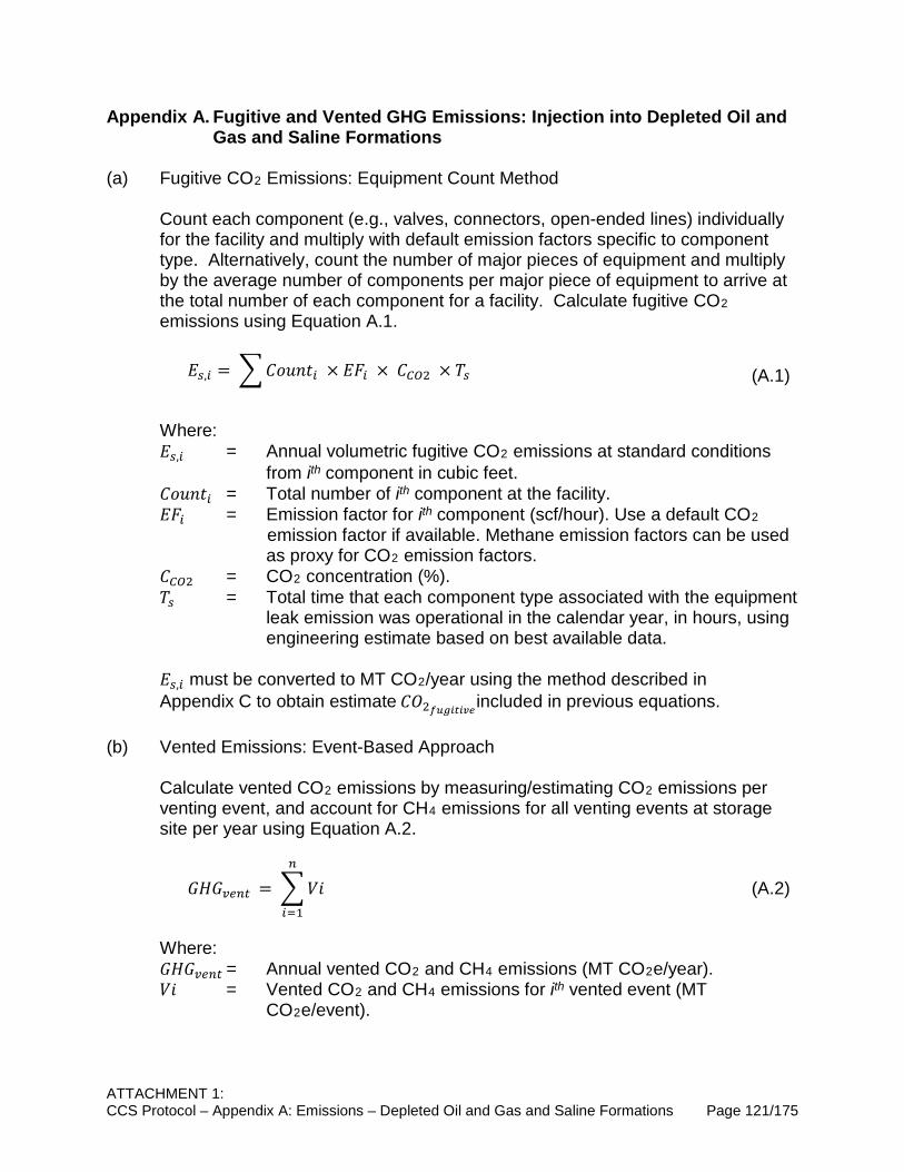
ATTACHMENT 1: CCS Protocol – Appendix A: Emissions – Depleted Oil and Gas and Saline Formations Page 121/175
Appendix A. Fugitive and Vented GHG Emissions: Injection into Depleted Oil and Gas and Saline Formations
(a) Fugitive CO2 Emissions: Equipment Count Method
Count each component (e.g., valves, connectors, open-ended lines) individually for the facility and multiply with default emission factors specific to component type. Alternatively, count the number of major pieces of equipment and multiply by the average number of components per major piece of equipment to arrive at the total number of each component for a facility. Calculate fugitive CO2 emissions using Equation A.1. 𝐸𝐸𝑡𝑡,𝑟𝑟 = �𝐶𝐶𝐸𝐸𝐶𝐶𝐶𝐶𝐶𝐶𝑟𝑟 × 𝐸𝐸𝐸𝐸𝑟𝑟 × 𝐶𝐶𝑑𝑑𝐶𝐶2 × 𝑇𝑇𝑡𝑡 (A.1)
Where: 𝐸𝐸𝑡𝑡,𝑟𝑟 = Annual volumetric fugitive CO2 emissions at standard conditions
from ith component in cubic feet. 𝐶𝐶𝐸𝐸𝐶𝐶𝐶𝐶𝐶𝐶𝑟𝑟 = Total number of ith component at the facility. 𝐸𝐸𝐸𝐸𝑟𝑟 = Emission factor for ith component (scf/hour). Use a default CO2
emission factor if available. Methane emission factors can be used as proxy for CO2 emission factors.
𝐶𝐶𝑑𝑑𝐶𝐶2 = CO2 concentration (%). 𝑇𝑇𝑡𝑡 = Total time that each component type associated with the equipment
leak emission was operational in the calendar year, in hours, using engineering estimate based on best available data.
𝐸𝐸𝑡𝑡,𝑟𝑟 must be converted to MT CO2/year using the method described in Appendix C to obtain estimate 𝐶𝐶𝐶𝐶2𝑓𝑓𝑓𝑓𝑓𝑓𝑖𝑖𝑖𝑖𝑖𝑖𝑣𝑣𝑖𝑖 included in previous equations.
(b) Vented Emissions: Event-Based Approach Calculate vented CO2 emissions by measuring/estimating CO2 emissions per venting event, and account for CH4 emissions for all venting events at storage site per year using Equation A.2. 𝐺𝐺𝐺𝐺𝐺𝐺𝑣𝑣𝑟𝑟𝑟𝑟𝑟𝑟 = �𝑉𝑉𝐸𝐸
𝑟𝑟
𝑟𝑟=1
(A.2)
Where: 𝐺𝐺𝐺𝐺𝐺𝐺𝑣𝑣𝑟𝑟𝑟𝑟𝑟𝑟 = Annual vented CO2 and CH4 emissions (MT CO2e/year). 𝑉𝑉𝐸𝐸 = Vented CO2 and CH4 emissions for ith vented event (MT
CO2e/event).

This Page Left Intentionally Blank
APPENDIX B
CO2 VENTING AND FUGITIVE EMISSIONS FROM CO2-EOR
OPERATIONS

This Page Left Intentionally Blank

ATTACHMENT 1: CCS Protocol – Appendix B: Emissions – CO2-EOR Page 125/175
Appendix B. CO2 Venting and Fugitive Emissions from CO2-EOR Operations (a) Metered natural gas pneumatic device and pump vented CO2 emissions.
(1) Calculate CO2 emissions from a natural gas-powered continuous high bleed
control device and pneumatic pump vented using the method specified in paragraph (a)(1) of section 95153 in the Regulation for the Mandatory Reporting of Greenhouse Gas Emissions (MRR)11 when the natural gas flow to the device is metered.
(b) Non-metered natural gas pneumatic device vented emissions.
(1) Calculate CO2 emissions from all non-metered natural gas-powered pneumatic intermittent bleed and continuous low and high bleed devices using the equation in paragraph 95153(a)(2) of MRR.
(c) Acid gas removal vents.
(1) For AGR vents (including processes such as amine, membrane, molecular sieve or other absorbents and adsorbents), calculate emissions for CO2 only (not CH4) vented directly to the atmosphere or emitted through a flare, engine (e.g., permeate from a membrane or de-adsorbed gas from a pressure swing adsorber used as fuel supplement), or sulfur recovery plant using the applicable calculation methodologies described in paragraphs 95153(c)(1)–(c)(10) of MRR.
(d) Dehydrator vents.
(1) Calculate annual CO2 emissions using any of the calculation methodologies described in paragraph 95153(d) of MRR.
(e) Gas well vented CO2 emissions during well completions and workovers.
(1) Use either the Methodology 1 or 2 described in paragraphs 95153(f)(1)–(f)(5) of MRR.
(f) Equipment and pipeline blowdowns.
(1) Calculate CO2 blowdown emissions from depressurizing equipment and natural gas pipelines to reduce system pressure for shutdowns resulting from human intervention or to take equipment out of service for maintenance (excluding depressurizing to a flare, over-pressure relief, operating pressure control vented and blowdown of non-GHG gases; desiccant dehydrator
11 CARB, 2014. Regulation for the Mandatory Reporting of Greenhouse Gas Emissions. Unofficial electronic version available at https://ww2.arb.ca.gov/mrr-regulation
ATTACHMENT 1: CCS Protocol – Appendix B: Emissions – CO2-EOR Page 126/175
blowdown vented before reloading is covered in paragraphs 95153 (d)(4) of MRR.
(g) Dump valves.
(1) Calculate CO2 emissions from gas-liquid separator liquid dump valves not closing by using the method found in 95153(i) of MRR.
(h) Well testing vented emissions.
(1) Calculate CO2 vented from oil well testing using the methods found in paragraphs of 95153(j)(1)–(j)(6) of MRR.
(i) Associated gas.
(1) Calculate CO2 in associated gas vented not in conjunction with well testing using the methods found in paragraphs of 95153(k)(1)–(k)(6) of MRR.
(j) Centrifugal compressor vented emissions.
(1) Calculate CO2 emissions from both wet seal and dry seal centrifugal compressor using the methods described in paragraphs of 95153(m)(1)–(m)(8) of MRR.
(k) Reciprocating compressor vented emissions.
(1) Calculate CO2 emissions from all reciprocating compressor vents using the methods described in paragraphs of 95153(n)(1)–(n)(7) of MRR.
(l) EOR injection pump blowdown emissions.
(1) Calculate CO2 pump blowdown emissions from EOR operations using critical CO2 injection using Equation 33 as described in section 95153(u) of MRR.
(m) Fugitive CO2 emissions from valves, connectors, open ended lines, pressure
relief valves, pumps, flanges, and other equipment leak sources (such as instruments, loading arms, stuffing boxes, compressor seals, dump lever arms, and breather caps).
(1) Perform leak detection tests in accordance with procedures as described in the MRR. If leakage is detected from the equipment listed above during annual leak detection tests, calculate fugitive emissions (CO2) per component type in which leak is detected using Equation 25 in section 95153(o) of MRR for each component type. Default fugitive emission factors for Equation 25 are reported in Tables E4 to E6; or
ATTACHMENT 1: CCS Protocol – Appendix B: Emissions – CO2-EOR Page 127/175
(2) Calculate fugitive emissions from all equipment using the population count and emission factors as described in section 95153(p) of MRR.

This Page Left Intentionally Blank

APPENDIX C
CONVERTING VOLUME OF CO2 TO MASS

This Page Left Intentionally Blank
ATTACHMENT 1: CCS Protocol – Appendix C: Converting Volume to Mass Page 131/175
Appendix C. Converting Volume of CO2 to Mass (a) When volumetric emissions of CO2 are measured at actual temperatures and
pressures, convert them to volumetric emissions at standard conditions (25°C and 1 atm) using Equations 29 and 30 in MRR.
(b) Calculate GHG mass emissions by converting the GHG volumetric emissions at
standard conditions into mass emissions using Equation 32 described in section 95153(t) of MRR.

This Page Left Intentionally Blank

APPENDIX D
DATA MEASUREMENT/GENERATION AND REPORTING FOR
ENERGY AND CHEMICAL INPUTS

This Page Left Intentionally Blank
ATTACHMENT 1: CCS Protocol – Appendix D: Data – Energy and Chemical Inputs Page 135/175
Appendix D. Data Measurement/Generation and Reporting for Energy and Chemical Inputs
(a) Amounts of fuels used:
(1) Fuel receipts/invoices or flow meter readings whichever applicable; (2) The flow meter readings must be corrected for temperature and pressure.
Density estimates used for emission quantification purposes must be adjusted to corrected standardized temperatures and pressures;
(3) Flow meters must be placed based on manufacturer recommendations and
must operate within manufacturers specified operating conditions at all times; and
(4) Flow meters must be calibrated according to manufacturer specifications and
must be checked and calibrated at regular intervals according to these specifications.
(5) In cases where the same fuel is used for CCS and other unrelated activities
and share the same meter or receipts/invoices, or when fuel receipts/invoices or metered data are not available, estimates with justification for the chosen methodology can be used with approval from the Executive Officer.
(b) Electricity consumption:
(1) Utility receipts/invoices or metered data for off-grid electricity use. In the
absence of these data, maximum power rating for each type of equipment and operating hours can be used to estimate electricity use with approval from the Executive Officer.
(2) In certain cases other loads may be tied into the same electricity meter. In
such instances, estimates with justification for the chosen methodology can be used with approval from the Executive Officer.
(3) Electricity meters must be calibrated in accordance with manufacturer
specifications and must be checked and calibrated at regular intervals according to these specifications.
(c) Steam consumption:
(1) Utility receipts/invoices or metered data for on-site steam production whichever applicable.
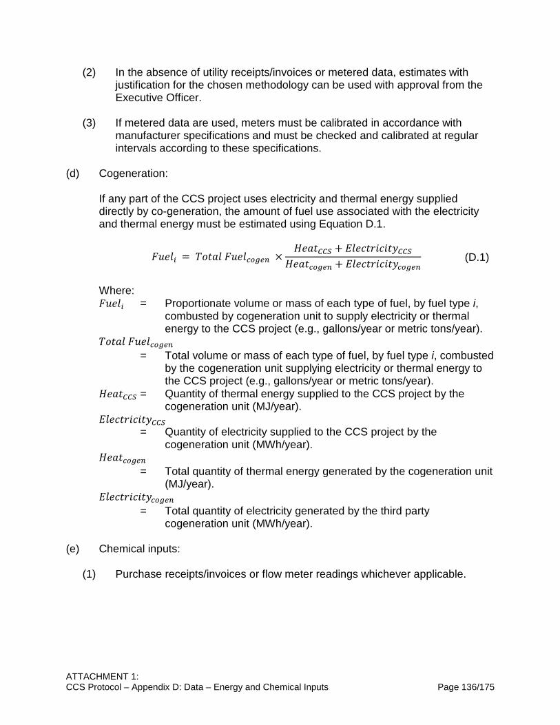
ATTACHMENT 1: CCS Protocol – Appendix D: Data – Energy and Chemical Inputs Page 136/175
(2) In the absence of utility receipts/invoices or metered data, estimates with justification for the chosen methodology can be used with approval from the Executive Officer.
(3) If metered data are used, meters must be calibrated in accordance with
manufacturer specifications and must be checked and calibrated at regular intervals according to these specifications.
(d) Cogeneration:
If any part of the CCS project uses electricity and thermal energy supplied directly by co-generation, the amount of fuel use associated with the electricity and thermal energy must be estimated using Equation D.1. 𝐸𝐸𝐶𝐶𝐸𝐸𝐹𝐹𝑟𝑟 = 𝑇𝑇𝐸𝐸𝐶𝐶𝑇𝑇𝐹𝐹 𝐸𝐸𝐶𝐶𝐸𝐸𝐹𝐹𝑟𝑟𝑟𝑟𝑐𝑐𝑟𝑟𝑟𝑟 ×
𝐺𝐺𝐸𝐸𝑇𝑇𝐶𝐶𝑑𝑑𝑑𝑑𝐶𝐶 + 𝐸𝐸𝐹𝐹𝐸𝐸𝐸𝐸𝐶𝐶𝐸𝐸𝐸𝐸𝐸𝐸𝐸𝐸𝐶𝐶𝐸𝐸𝑑𝑑𝑑𝑑𝐶𝐶𝐺𝐺𝐸𝐸𝑇𝑇𝐶𝐶𝑟𝑟𝑟𝑟𝑐𝑐𝑟𝑟𝑟𝑟 + 𝐸𝐸𝐹𝐹𝐸𝐸𝐸𝐸𝐶𝐶𝐸𝐸𝐸𝐸𝐸𝐸𝐸𝐸𝐶𝐶𝐸𝐸𝑟𝑟𝑟𝑟𝑐𝑐𝑟𝑟𝑟𝑟
(D.1)
Where: 𝐸𝐸𝐶𝐶𝐸𝐸𝐹𝐹𝑟𝑟 = Proportionate volume or mass of each type of fuel, by fuel type i,
combusted by cogeneration unit to supply electricity or thermal energy to the CCS project (e.g., gallons/year or metric tons/year).
𝑇𝑇𝐸𝐸𝐶𝐶𝑇𝑇𝐹𝐹 𝐸𝐸𝐶𝐶𝐸𝐸𝐹𝐹𝑟𝑟𝑟𝑟𝑐𝑐𝑟𝑟𝑟𝑟 = Total volume or mass of each type of fuel, by fuel type i, combusted
by the cogeneration unit supplying electricity or thermal energy to the CCS project (e.g., gallons/year or metric tons/year).
𝐺𝐺𝐸𝐸𝑇𝑇𝐶𝐶𝑑𝑑𝑑𝑑𝐶𝐶 = Quantity of thermal energy supplied to the CCS project by the cogeneration unit (MJ/year).
𝐸𝐸𝐹𝐹𝐸𝐸𝐸𝐸𝐶𝐶𝐸𝐸𝐸𝐸𝐸𝐸𝐸𝐸𝐶𝐶𝐸𝐸𝑑𝑑𝑑𝑑𝐶𝐶 = Quantity of electricity supplied to the CCS project by the
cogeneration unit (MWh/year). 𝐺𝐺𝐸𝐸𝑇𝑇𝐶𝐶𝑟𝑟𝑟𝑟𝑐𝑐𝑟𝑟𝑟𝑟 = Total quantity of thermal energy generated by the cogeneration unit
(MJ/year). 𝐸𝐸𝐹𝐹𝐸𝐸𝐸𝐸𝐶𝐶𝐸𝐸𝐸𝐸𝐸𝐸𝐸𝐸𝐶𝐶𝐸𝐸𝑟𝑟𝑟𝑟𝑐𝑐𝑟𝑟𝑟𝑟 = Total quantity of electricity generated by the third party
cogeneration unit (MWh/year).
(e) Chemical inputs:
(1) Purchase receipts/invoices or flow meter readings whichever applicable.

APPENDIX E
EMISSION FACTORS AND COMPONENT COUNTS

This Page Left Intentionally Blank

ATTACHMENT 1: CCS Protocol – Appendix E: Emission Factors Page 139/175
Appendix E. Emission Factors and Component Counts Note: Stationary emissions factors in Tables E1 to E3 may be used only if they are not available in CA-GREET.
Table E1. Stationary Emission Factors for Fossil Fuel Combustion12
Coal and Coke kg CO2/ton g CH4/ton g N2O/ton Anthracite (coal) 2602 276 40 Bituminous (coal) 2325 274 40 Sub-bituminous (coal) 1676 190 28 Lignite 1389 156 23 Mixed (commercial) 2016 235 34 Mixed (electric power sector) 1885 217 32 Mixed (industrial sector) 2468 289 42 Mixed (commercial) 2116 246 36 Coal Coke 2819 273 40 Fossil-derived Fuels (solid) kg CO2/ton g CH4/ton g N2O/ton
Municipal Solid Waste 902 318 42 Petroleum Coke (Solid) 3072 960 126
Plastics 2850 1216 160 Tires 2407 896 118
Fossil-derived Fuels (gaseous) kg CO2/scf g CH4/scf g N2O/scf
Blast Furnace Gas 0.02524 0.000002 0.000009 Coke Oven Gas 0.02806 0.000288 0.00006
Fuel Gas 0.08189 0.004164 0.000833 Propane Gas 0.15463 0.000055 0.000252
Note: Ton refers to short ton. While using Tables E1 to E3, CO and VOC emissions may need to be estimated if possible.
12 US EPA. Direct Emissions from Stationary Combustion Sources. (2016). Available at https://www.epa.gov/sites/production/files/2016-03/documents/stationaryemissions_3_2016.pdf

ATTACHMENT 1: CCS Protocol – Appendix E: Emission Factors Page 140/175
Table E2. Stationary Emission Factors for Petroleum Fuel Combustion12
Petroleum Products kg CO2/gal g CH4/gal g N2O/gal
Asphalt and Road Oil 11.91 0.47 0.09 Aviation Gasoline 8.31 0.36 0.07
Butane 6.67 0.31 0.06 Butylene 7.22 0.32 0.06
Crude Oil 10.29 0.41 0.08 Distillate Fuel Oil No .1 10.18 0.42 0.08 Distillate Fuel Oil No .2 10.21 0.41 0.08 Distillate Fuel Oil No. 4 10.96 0.44 0.09
Ethane 4.05 0.2 0.04 Ethylene 3.83 0.17 0.03
Heavy Gas Oils 11.09 0.44 0.09 Isobutane 6.43 0.3 0.06
Isobutylene 7.09 0.31 0.06 Kerosene 10.15 0.41 0.08
Kerosene-Type Jet Fuel 9.75 0.41 0.08 Liquefied Petroleum Gases
(LPG) 5.68 0.28 0.06 Lubricants 10.69 0.43 0.09
Motor Gasoline 8.78 0.38 0.08 Naphtha (<401 deg F) 8.5 0.38 0.08
Natural Gasoline 7.36 0.33 0.07 Other Oil (>401 deg F) 10.59 0.42 0.08
Pentanes Plus 7.7 0.33 0.07 Petrochemical Feedstocks 8.88 0.38 0.08
Petroleum Coke 14.64 0.43 0.09 Propane 5.72 0.27 0.05
Propylene 6.17 0.27 0.05 Residual Fuel Oil No. 5 10.21 0.42 0.08 Residual Fuel Oil No. 6 11.27 0.45 0.09
Special Naphtha 9.04 0.38 0.08 Unfinished Oils 10.36 0.42 0.08
Used Oil 10.21 0.41 0.08
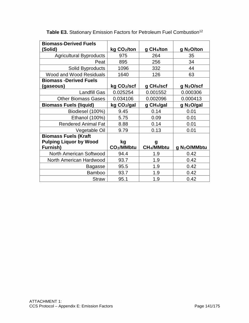
ATTACHMENT 1: CCS Protocol – Appendix E: Emission Factors Page 141/175
Table E3. Stationary Emission Factors for Petroleum Fuel Combustion12
Biomass-Derived Fuels (Solid) kg CO2/ton g CH4/ton g N2O/ton
Agricultural Byproducts 975 264 35 Peat 895 256 34
Solid Byproducts 1096 332 44 Wood and Wood Residuals 1640 126 63
Biomass -Derived Fuels (gaseous) kg CO2/scf g CH4/scf g N2O/scf
Landfill Gas 0.025254 0.001552 0.000306 Other Biomass Gases 0.034106 0.002096 0.000413
Biomass Fuels (liquid) kg CO2/gal g CH4/gal g N2O/gal Biodiesel (100%) 9.45 0.14 0.01
Ethanol (100%) 5.75 0.09 0.01 Rendered Animal Fat 8.88 0.14 0.01
Vegetable Oil 9.79 0.13 0.01 Biomass Fuels (Kraft Pulping Liquor by Wood Furnish)
kg CO2/MMbtu
g CH4/MMbtu g N2O/MMbtu
North American Softwood 94.4 1.9 0.42 North American Hardwood 93.7 1.9 0.42
Bagasse 95.5 1.9 0.42 Bamboo 93.7 1.9 0.42
Straw 95.1 1.9 0.42
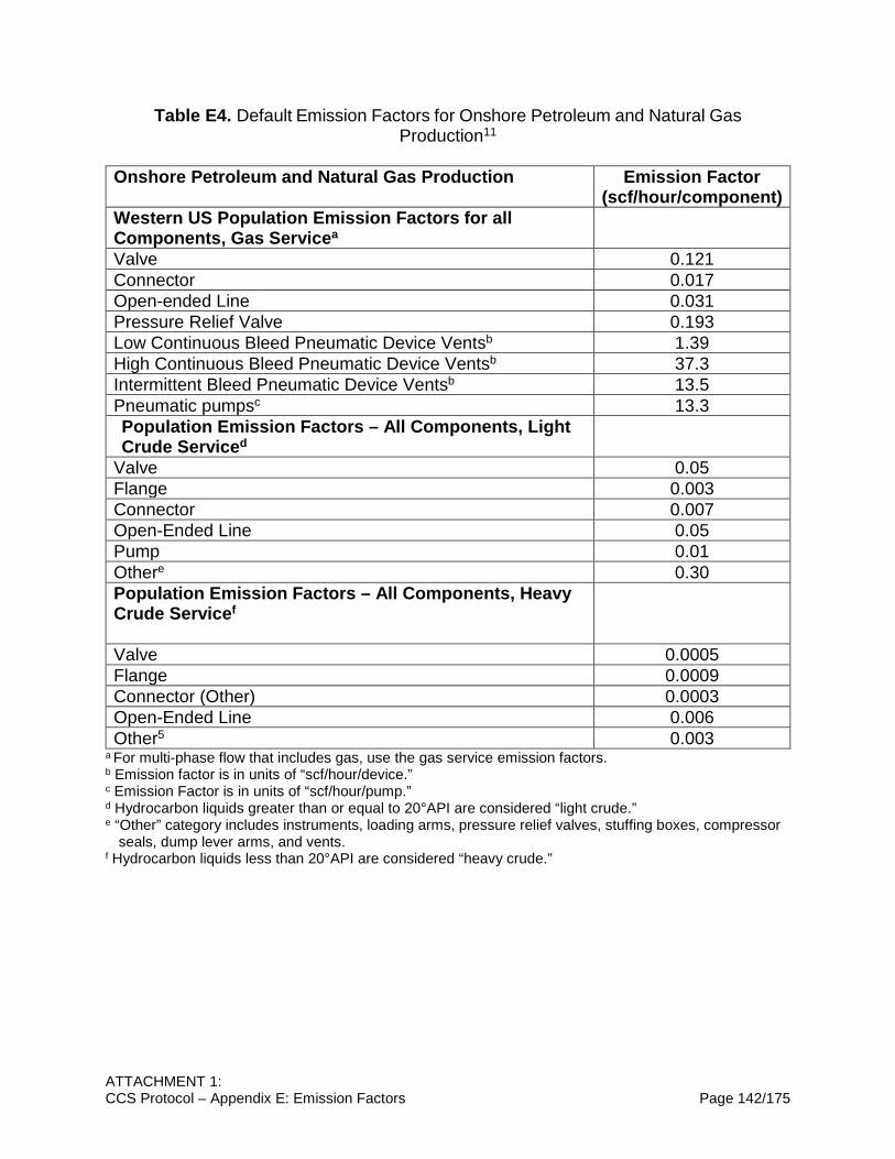
ATTACHMENT 1: CCS Protocol – Appendix E: Emission Factors Page 142/175
Table E4. Default Emission Factors for Onshore Petroleum and Natural Gas Production11
Onshore Petroleum and Natural Gas Production Emission Factor
(scf/hour/component) Western US Population Emission Factors for all Components, Gas Servicea
Valve 0.121 Connector 0.017 Open-ended Line 0.031 Pressure Relief Valve 0.193 Low Continuous Bleed Pneumatic Device Ventsb 1.39 High Continuous Bleed Pneumatic Device Ventsb 37.3 Intermittent Bleed Pneumatic Device Ventsb 13.5 Pneumatic pumpsc 13.3 Population Emission Factors – All Components, Light Crude Serviced
Valve 0.05 Flange 0.003 Connector 0.007 Open-Ended Line 0.05 Pump 0.01 Othere 0.30 Population Emission Factors – All Components, Heavy Crude Servicef
Valve 0.0005 Flange 0.0009 Connector (Other) 0.0003 Open-Ended Line 0.006 Other5 0.003
a For multi-phase flow that includes gas, use the gas service emission factors. b Emission factor is in units of “scf/hour/device.” c Emission Factor is in units of “scf/hour/pump.” d Hydrocarbon liquids greater than or equal to 20°API are considered “light crude.” e “Other” category includes instruments, loading arms, pressure relief valves, stuffing boxes, compressor
seals, dump lever arms, and vents. f Hydrocarbon liquids less than 20°API are considered “heavy crude.”

ATTACHMENT 1: CCS Protocol – Appendix E: Emission Factors Page 143/175
Table E5. Default Average Component Counts for Major Crude Oil Production Equipment11
Major Equipment
Valves Flanges Connectors Open-Ended Lines
Other Components
Wellhead 5 10 4 0 1 Separator 6 12 10 0 0 Heater-Treater 8 12 20 0 0 Header 5 10 4 0 0
Table E6. Default Average Component Counts for Major Onshore Natural Gas Production Equipment11
Major Equipment
Valves Connectors Open-Ended Lines
Pressure Relief Valves
Wellheads 11 36 1 0 Separators 34 106 6 2 Meters/Piping 14 51 1 1 Compressors 73 179 3 4 In-Line Heaters 14 65 2 1 Dehydrators 24 90 2 2

This Page Left Intentionally Blank

APPENDIX F
EMISSIONS FROM CO2 ENTRAINED IN PRODUCED OIL AND
GAS

This Page Left Intentionally Blank

ATTACHMENT 1: CCS Protocol – Appendix F: Entrained Emissions Page 147/175
Appendix F. Emissions from CO2 Entrained in Produced Oil and Gas (a) Annual CO2 Fugitive Emissions Entrained in Produced Oil and Gas13 𝐶𝐶𝐶𝐶2𝑖𝑖𝑖𝑖𝑖𝑖𝑒𝑒𝑒𝑒𝑖𝑖𝑖𝑖𝑖𝑖𝑖𝑖 = (𝑉𝑉𝑐𝑐𝑐𝑐𝑡𝑡 × %𝐶𝐶𝐶𝐶2𝑓𝑓𝑒𝑒𝑡𝑡 × 𝜌𝜌𝐶𝐶𝐶𝐶2 × 0.001) + (𝑀𝑀𝑤𝑤𝑐𝑐𝑟𝑟𝑟𝑟𝑟𝑟 × 𝐸𝐸𝑑𝑑𝐶𝐶2−𝑤𝑤𝑐𝑐𝑟𝑟𝑟𝑟𝑟𝑟)
+ (𝑀𝑀𝑟𝑟𝑟𝑟𝑒𝑒 × 𝐸𝐸𝑑𝑑𝐶𝐶2−𝑟𝑟𝑟𝑟𝑒𝑒) (F.1)
Where: 𝐶𝐶𝐶𝐶2𝑖𝑖𝑖𝑖𝑖𝑖𝑒𝑒𝑒𝑒𝑖𝑖𝑖𝑖𝑖𝑖𝑖𝑖 = Emissions or other losses of CO2 entrained or dissolved in crude
oil/other hydrocarbons, produced water and natural gas that have been separated from the produced CO2 for sale or disposal. Calculated based on quantities of crude oil, water and gas produced and the CO2 content of each product (MT CO2/year).
𝑉𝑉𝑐𝑐𝑐𝑐𝑡𝑡 = Volume of natural gas or fuel gas, produced from the formation that CO2 is being injected into, that is sold to third parties or input into a natural gas pipeline in year y (m3 /year), measured at standard conditions.
𝜌𝜌𝐶𝐶𝐶𝐶2 = Density of CO2 at standard conditions (1.899 kg/m3 or 0.0538 kg/ft3). %𝐶𝐶𝐶𝐶2𝑓𝑓𝑒𝑒𝑡𝑡 = % CO2 in the natural gas or fuel gas that is sold to third parties or input
into a natural gas pipeline, in year y (% volume). 𝑀𝑀𝑤𝑤𝑐𝑐𝑟𝑟𝑟𝑟𝑟𝑟 = Mass of water produced from the formation that CO2 is being injected
into, that is disposed of or otherwise not re-injected back into the formation (MT/year).
𝐸𝐸𝑑𝑑𝐶𝐶2−𝑤𝑤𝑐𝑐𝑟𝑟𝑟𝑟𝑟𝑟 = Mass fraction of CO2 in the water produced from the formation. 𝑀𝑀𝑟𝑟𝑟𝑟𝑒𝑒 = Mass of crude oil and other hydrocarbons produced from the formation
that CO2 is being injected into (MT/year). 𝐸𝐸𝑑𝑑𝐶𝐶2−𝑟𝑟𝑟𝑟𝑒𝑒 = Mass fraction of CO2 in the crude oil and other hydrocarbons produced
from the formation (MT/year).
13 The American Carbon Registry “Methodology for Greenhouse Gas Emission Reductions from Carbon Capture and Storage Projects,” Version 1 (2015). Available at http://americancarbonregistry.org/carbon-accounting/standards-methodologies/carbon-capture-and-storage-in-oil-and-gas-reservoirs/acr-ccs-methodology-v1-0-final.pdf.

This Page Left Intentionally Blank
APPENDIX G
DETERMINATION OF A CCS PROJECT’S RISK RATING FOR DETERMINING ITS CONTRIBUTION TO THE LCFS BUFFER
ACCOUNT

This Page Left Intentionally Blank
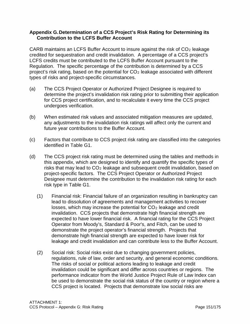
ATTACHMENT 1: CCS Protocol – Appendix G: Risk Rating Page 151/175
Appendix G. Determination of a CCS Project’s Risk Rating for Determining its Contribution to the LCFS Buffer Account
CARB maintains an LCFS Buffer Account to insure against the risk of CO2 leakage credited for sequestration and credit invalidation. A percentage of a CCS project’s LCFS credits must be contributed to the LCFS Buffer Account pursuant to the Regulation. The specific percentage of the contribution is determined by a CCS project’s risk rating, based on the potential for CO2 leakage associated with different types of risks and project-specific circumstances. (a) The CCS Project Operator or Authorized Project Designee is required to
determine the project’s invalidation risk rating prior to submitting their application for CCS project certification, and to recalculate it every time the CCS project undergoes verification.
(b) When estimated risk values and associated mitigation measures are updated, any adjustments to the invalidation risk ratings will affect only the current and future year contributions to the Buffer Account.
(c) Factors that contribute to CCS project risk rating are classified into the categories identified in Table G1.
(d) The CCS project risk rating must be determined using the tables and methods in this appendix, which are designed to identify and quantify the specific types of risks that may lead to CO2 leakage and subsequent credit invalidation, based on project-specific factors. The CCS Project Operator or Authorized Project Designee must determine the contribution to the invalidation risk rating for each risk type in Table G1.
(1) Financial risk: Financial failure of an organization resulting in bankruptcy can lead to dissolution of agreements and management activities to recover losses, which may increase the potential for CO2 leakage and credit invalidation. CCS projects that demonstrate high financial strength are expected to have lower financial risk. A financial rating for the CCS Project Operator from Moody’s, Standard & Poor's, and Fitch, can be used to demonstrate the project operator’s financial strength. Projects that demonstrate high financial strength are expected to have lower risk for leakage and credit invalidation and can contribute less to the Buffer Account.
(2) Social risk: Social risks exist due to changing government policies,
regulations, rule of law, order and security, and general economic conditions. The risks of social or political actions leading to leakage and credit invalidation could be significant and differ across countries or regions. The performance indicator from the World Justice Project Rule of Law Index can be used to demonstrate the social risk status of the country or region where a CCS project is located. Projects that demonstrate low social risks are

ATTACHMENT 1: CCS Protocol – Appendix G: Risk Rating Page 152/175
expected to have lower risk for leakage and credit invalidation and will contribute less to the Buffer Account. The World Justice Project Rule of Law Index uses household and expert surveys to measure how the rule of law is experienced and perceived by the general public worldwide. The rule of law performance is measured using 44 indicators across eight primary rule of law factors: Constraints on Government Powers, Absence of Corruption, Open Government, Fundamental Rights, Order and Security, Regulatory Enforcement, Civil Justice, and Criminal Justice. Each of the primary rule of law factors is scored and ranked globally and against regional and income peers.
(3) Management risk: Management risk is the risk of management activities or
failure to follow best project management practices (such as restricting site access) that directly or indirectly could lead to leakage and credit invalidation. For a typical CCS project, illegal removals of the components of surface injection facilities such as an injection well head during the injection operation or any time before well plugging can potentially lead to a CO2 leakage and credit invalidation. Illegal removals of the components of surface injection facilities can occur either by trespass or outside of a planned set of management activities that are controlled by regulation. Illegal removals of the components of surface injection facilities are more likely to occur when there is a lack of controls and enforcement activities. Projects that demonstrate quality management of access controls and enforcement are expected to have less management risk and thus lower risk for leakage and credit invalidation and can contribute less to the Buffer Account.
(4) Site risk: Proper site selection is key to minimize the risk of leakage and credit
invalidation. Section C.2.1 sets forth a set of minimum site selection criteria to minimize the risk of CO2 leakage. Project operators have the option to go beyond the minimum criteria and contribute less to the Buffer Account.
(5) Well integrity risk: If wells are not constructed to the proper requirements, or if
well maintenance, operations, and plugs do not follow appropriately prescribed plans, wells may become potential conduits for leakage and cause credit invalidation. It is essential to follow appropriate construction requirements and prescribed operating plans to ensure that injection does not compromise the well or fracture the injection formation or confining zone. The U.S. EPA (U.S. Environmental Protection Agency) class VI well standards under the UIC (Underground Injection Control) program are designed for safe CO2 injection and protection of underground drinking water resources. The U.S. EPA class VI well standards are designed to avoid the movement of CO2 and other fluid from the storage complex to unauthorized zones, which in most cases will prevent the release of CO2 to the atmosphere. Conformance to the U.S. EPA class VI well regulations is an indicator of minimizing the risk of CO2 leakage using wells a conduit. Since wells are the primary remaining risk factor if a quality sequestration site has been chosen, projects that

ATTACHMENT 1: CCS Protocol – Appendix G: Risk Rating Page 153/175
demonstrate that all of their wells meet USEPA class VI well or equivalent requirements can contribute less to the Buffer Account.
Table G.1. CCS project contribution to CCS project risk rating based on risk types
Risk type Risk category Risk Rating
Contribution Financial Low Financial Risk:
CCS project operators that demonstrate their company has:
• a Moody’s rating of A or better; or • an equivalent rating from Standard & Poor's, and
Fitch
0%
Medium Financial Risk: CCS project operators that demonstrate their company has:
• a Moody’s rating of B or better meets; or • an equivalent rating from Standard & Poor's, and
Fitch
1%
High Financial Risk: CCS project operators that cannot make one of the two demonstrations above
2%
Social Low Social Risk: CCS projects located in countries or regions ranked among the top 20th percentile based on the World Justice Project Rule of Law Index
0%
Medium Social Risk: CCS projects located in countries or regions ranked between the 20th and 50th percentile based on the World Justice Project Rule of Law Index
1%
High Social Risk: CCS projects located in countries or regions that are not ranked, or are ranked below the 50th percentile based on the World Justice Project Rule of Law Index
3%
Management Low Management Risk: Demonstrated surface facility access control, e.g., injection site is fenced and well protected
1%
Higher Management Risk: Poor or no surface facility access control, e.g., injection site is open, or not fenced or protected
2%
Site Low Site Risk: Selected site has more than two good quality confining layers above the sequestration zone and a dissipation interval below the sequestration zone
1%
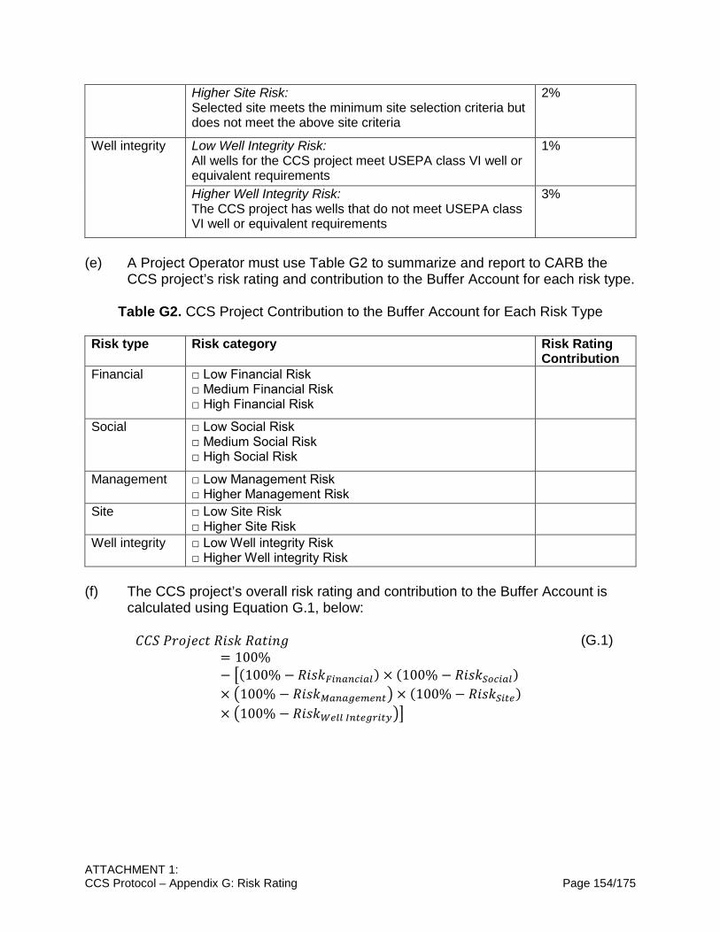
ATTACHMENT 1: CCS Protocol – Appendix G: Risk Rating Page 154/175
Higher Site Risk: Selected site meets the minimum site selection criteria but does not meet the above site criteria
2%
Well integrity Low Well Integrity Risk: All wells for the CCS project meet USEPA class VI well or equivalent requirements
1%
Higher Well Integrity Risk: The CCS project has wells that do not meet USEPA class VI well or equivalent requirements
3%
(e) A Project Operator must use Table G2 to summarize and report to CARB the
CCS project’s risk rating and contribution to the Buffer Account for each risk type.
Table G2. CCS Project Contribution to the Buffer Account for Each Risk Type Risk type Risk category Risk Rating
Contribution Financial □ Low Financial Risk
□ Medium Financial Risk □ High Financial Risk
Social □ Low Social Risk □ Medium Social Risk □ High Social Risk
Management □ Low Management Risk □ Higher Management Risk
Site □ Low Site Risk □ Higher Site Risk
Well integrity □ Low Well integrity Risk □ Higher Well integrity Risk
(f) The CCS project’s overall risk rating and contribution to the Buffer Account is
calculated using Equation G.1, below:
𝐶𝐶𝐶𝐶𝑈𝑈 𝑃𝑃𝐸𝐸𝐸𝐸𝑃𝑃𝐸𝐸𝐸𝐸𝐶𝐶 𝐵𝐵𝐸𝐸𝑅𝑅𝑅𝑅 𝐵𝐵𝑇𝑇𝐶𝐶𝐸𝐸𝐶𝐶𝑅𝑅= 100%− �(100% − 𝐵𝐵𝐸𝐸𝑅𝑅𝑅𝑅𝐹𝐹𝑟𝑟𝑟𝑟𝑐𝑐𝑟𝑟𝑟𝑟𝑟𝑟𝑐𝑐𝑒𝑒) × (100% − 𝐵𝐵𝐸𝐸𝑅𝑅𝑅𝑅𝐶𝐶𝑟𝑟𝑟𝑟𝑟𝑟𝑐𝑐𝑒𝑒)× �100% − 𝐵𝐵𝐸𝐸𝑅𝑅𝑅𝑅𝑀𝑀𝑐𝑐𝑟𝑟𝑐𝑐𝑐𝑐𝑟𝑟𝑐𝑐𝑟𝑟𝑟𝑟𝑟𝑟� × (100% − 𝐵𝐵𝐸𝐸𝑅𝑅𝑅𝑅𝐶𝐶𝑟𝑟𝑟𝑟𝑟𝑟)× �100% − 𝐵𝐵𝐸𝐸𝑅𝑅𝑅𝑅𝑊𝑊𝑟𝑟𝑒𝑒𝑒𝑒 𝐼𝐼𝑟𝑟𝑟𝑟𝑟𝑟𝑐𝑐𝑟𝑟𝑟𝑟𝑟𝑟𝑒𝑒��
(G.1)

APPENDIX B – ATTACHMENT 2:
CCS PROTOCOL SPECIFIC PURPOSE AND RATIONALE

TABLE OF CONTENTS
A. DEFINITIONS AND APPLICABILITY ...................................................................... 157
B. ACCOUNTING REQUIREMENTS FOR CCS PROJECTS UNDER LCFS ............. 158
C. PERMANENCE REQUIREMENTS FOR GEOLOGIC SEQUESTRATION ............ 159
Section C1. Permanence Certification of Geologic Carbon Sequestration .................. 161
Section C2. Site Characterization ............................................................................... 162
Section C2.1. Minimum Site Selection Criteria ............................................................ 162
Section C2.2. Risk Assessment .................................................................................. 164
Section C2.3. Geologic and Hydrogeologic Evaluation Requirement .......................... 165
Section C2.4. Area of Review Delineation and Corrective Action ............................... 166
Section C2.5. Baseline Monitoring .............................................................................. 167
Section C3. Injection Well Construction and Operating Requirements ....................... 168
Section C4. Injection Monitoring Requirements .......................................................... 169
Section C5. Well Plugging, Post-Injection Site Care, and Site Closure ....................... 169
Section C6. Emergency and Remedial Response ...................................................... 172
Section C7. Financial Responsibility ........................................................................... 173
Section C8. Modification or Revocation and Reissuance of Permanence Certification173
Section C9. Legal Understanding/Contracts, Post-Closure Care ................................ 174

ATTACHMENT 2: CCS Protocol Specific Purpose and Rational Page 157/175
CCS PROTOCOL SPECIFIC PURPOSE AND RATIONALE A. DEFINITIONS AND APPLICABILITY
Section A.1. Purpose
Description of the Problem The Low Carbon Fuel Standard (LCFS) requires CCS projects to use a Board approved quantification methodology (QM) in order to generate credits. The LCFS requires that the QM include monitoring, reporting, verification, and provisions for ensuring that CCS projects achieve permanent sequestration of CO2. Additionally, all GHG emissions reductions credited under LCFS from CCS projects must be real, permanent, additional, quantifiable, verifiable, and enforceable. Proposed Solution Staff proposes to adopt and incorporate the CCS Protocol into the LCFS regulation by reference. The CCS Protocol includes requirements for both accounting and permanence and, if adopted, would satisfy the need for a CCS QM in the LCFS. The Accounting Requirements specify how to calculate net GHG emission reductions associated with CCS projects, including emissions from CCS operations, CO2 surface leakage, above ground fugitive emissions, and post closure emissions. Applicants must use the Accounting Requirements to calculate credit amounts or carbon intensity reductions for CCS projects under LCFS. The Permanence Requirements include provisions to ensure that GHG emission reductions from CCS are permanent by remaining sequestered for at least 100 years in order for CCS projects to qualify for GHG reductions (or non-emissions) under LCFS. CCS projects must comply with the totality of the CCS Protocol in order to obtain Permanence Certification. Rationale Supporting the Proposed Solution The proposed CCS Protocol will allow CCS projects to participate in the LCFS, account for emission reduction credits via a quantification methodology outlined in the Accounting Requirements, ensure the safe and permanent storage of CO2 following the Permanence Requirements, and ensure that all GHG emissions reductions are real, permanent, additional, quantifiable, verifiable, and enforceable.
Section A.2. Definitions and Acronyms
Description of the Problem The CCS Protocol needs a uniform set of definitions and acronyms for clarity. Proposed Solution Staff proposes to include a section of definitions and acronyms. Rationale Supporting the Proposed Solution This section ensures clarity and consistency for terminology used in the CCS Protocol.
ATTACHMENT 2: CCS Protocol Specific Purpose and Rational Page 158/175
B. ACCOUNTING REQUIREMENTS FOR CCS PROJECTS UNDER LCFS Description of the Problem The LCFS requires CCS projects to use a Board approved QM that includes clear GHG emissions accounting requirements in order to generate credits. Under the LCFS, CCS projects need to properly account for lifecycle emissions of GHGs. Proposed Solution In order to fulfill CARB’s commitment to adopt a quantification methodology for CCS projects, staff proposes to adopt a CCS QM in the form of Accounting Requirements within the CCS Protocol. The Accounting Requirements provide a framework to calculate net emission reductions for CCS projects. Consistent with LCFS regulation, the proposed Accounting Requirements use a lifecycle approach, incorporating direct and indirect GHG emissions from CO2 capture, transport, injection, and sequestration. Likewise, consistent with the LCFS GHG accounting approach, CO2, CO, CH4, N2O, and volatile organic compounds (VOCs) emissions are considered; However, CO, CH4, N2O, and VOCs present in the injected CO2 stream are not counted toward the sequestered amount for the purpose of calculating emission reductions that would qualify for crediting. The Accounting Requirements include two separate system boundaries for (1) CO2-EOR and (2) CO2 storage in saline formations/depleted oil and gas reservoirs. The system boundaries show the sources of GHG emissions from various stages of CCS that must be included when calculating CCS emission reductions. In either case (1) or case (2), above, the system is bounded by CO2 capture in the beginning, and CO2 injection into an underground geologic formation and storage at the end. The Accounting Requirements calculate CCS credits based on the difference between the amounts of CO2 injected and lifecycle CCS project emissions. In CO2-EOR, GHG emissions occur both at the oilfield, due to CO2 injection, and at the recycling facility, due to activity associated with crude oil and gas production. Because of the overlap in CCS activities between the capture and sequestration site, these emissions could be allocated in some proportion to either the CCS project or the produced oil. Staff proposes to use a mass balance approach and assign GHG emissions that are associated with the fuel and electricity used for the separation, recycling, and injection of CO2 to CCS projects. The remainder of the fuel and electricity use emissions are assigned to crude oil and gas production. Likewise, fugitive and vented CO2 emissions at the CO2-EOR site are assigned to CCS projects while fugitive and vented CH4 emissions are assigned to crude oil and gas production. To ensure that CCS emissions reductions are accurately quantified, the Accounting Requirements include accounting for atmospheric CO2 leakage. Because the CO2 is sequestered underground in deep geologic formations, indirect monitoring techniques must be used to identify and quantify CO2 leakage out of the sequestration zone. Due

ATTACHMENT 2: CCS Protocol Specific Purpose and Rational Page 159/175
to the detection limitations of indirect monitoring, staff proposes to deduct half the detection limit of the monitoring methods from the calculated emissions reductions to account for potential undetected leaks. Staff chose to deduct half the detection limit based on stakeholder recommendation, and to acknowledge that properly sited, constructed, and monitored projects are not expected to leak CO2, while also being conservative to account for the fact that there are limitations to all monitoring techniques. Additionally, staff proposes that any deliberate CO2 release (of intentionally sequestered CO2) from active oil and gas reservoirs and transfer of the CO2 for use at other sites must be counted as emissions under the CCS Protocol. If the CO2 is transferred to another CO2-EOR injection site, that site could apply separately for crediting under the CCS Protocol. Staff also proposes to include direct land use GHG emissions in the Accounting Protocol if a CCS project results in land use change GHG emissions. A study by Cooney et al.14 shows that direct land use emissions from CO2-EOR related activities can be appreciable. Finally, staff proposes to include provisions for a buffer account in order to pool risk in case of potential leaks of CO2 to the atmosphere. Subsection B.3 specifies the methods to determine the amount of atmospheric leakage. Rationale Supporting the Proposed Solution The Accounting Requirements allow credit generation for CCS projects under the LCFS. A preliminary staff analysis indicates that the incorporation of CCS in the LCFS can incentivize a number of new CCS projects, which has the potential to result in annual CO2 sequestration of 1.4 -7.2 million metric tons (MMT) in California, and elsewhere, by 2030. CCS projects require significant capital investment and operational costs. CCS credits can provide a source of revenue to offset some of these costs, and thereby encourage the deployment of more CCS projects. Thus, CCS projects offer an additional tool for fuel providers to meet LCFS targets. Although the risk of atmospheric leakage for a properly managed CCS project is very low, the risk will not be zero. Staff set forth requirements on how to determine a CCS project’s invalidation risk rating, which covers the amount of credits that must be contributed to the buffer pool. For more information, see Chapter III section 95486(a)(3). C. PERMANENCE REQUIREMENTS FOR GEOLOGIC SEQUESTRATION
Purpose of the Permanence Requirements
Description of the Problem The LCFS requires CCS projects to use a Board approved QM in order to generate credits. The LCFS requires that the QM include monitoring, reporting, verification, and 14 Cooney, Gregory, et al. "Evaluating the climate benefits of CO2-enhanced oil recovery using life cycle analysis." Environmental science & technology 49.12 (2015): 7491-7500.

ATTACHMENT 2: CCS Protocol Specific Purpose and Rational Page 160/175
permanence requirements. If adopted, the CCS Protocol will satisfy the requirement for a QM for CCS. Proposed Solution Staff proposes to adopt permanence requirements as part of the CCS Protocol. The permanence requirements would ensure that CCS projects demonstrate that sequestered CO2 remains underground permanently, by staying within the sequestration zone for at least 100 years. Figure 7 illustrates the process for a typical project to comply with the Permanence Requirements. The Permanence Requirements involve two CARB certifications. The first certification required is the Sequestration Site Certification. This certification includes third-party review of the site characterization study and site certification-required plans by a registered Professional Geologist. Sequestration Site Certification must demonstrate that the geology of the site, as well as all plans for well construction, remediation, monitoring, emergency response, etc., are sound, and that the sequestration site is capable of permanent carbon sequestration. Sequestration Site Certification is required prior to CCS Project Certification, and ideally would be completed prior to well construction. CCS projects with developed sequestration sites may undergo Sequestration Site Certification after well construction has been completed, but they may be rejected due to poor geology, or they may require significant well reworking to meet the site requirements. The second certification required is CCS Project Certification. CCS Project Certification indicates that the CCS project has completed all prerequisite requirements for permanence under the CCS Protocol, including proper well construction and site preparation (e.g. installation of monitoring equipment). Once the CCS Project Operator has completed well construction and site preparation activities, the CCS Project Operator can submit an application for CCS Project Certification. CCS Project Certification requires third-party review by a Professional Petroleum Engineer. The CCS project would be eligible to generate credits after obtaining both sequestration and project certification, and by following all operating requirements as specified in the plans. For CCS projects in which the site characterization study has been completed, and the wells have already been constructed, CCS Project Operators can submit both their application for site and project certification, simultaneously, for CARB review. If CARB review shows that all site and construction requirements have been met, the CCS project can begin to generate credits. It is worth noting that CCS can occur today, and these two certifications are only required in order for a CCS project to generate credits under the LCFS. CARB has designed this certification process to outline requirements for permanence and site/operational conditions in order for CCS projects to qualify for crediting.

ATTACHMENT 2: CCS Protocol Specific Purpose and Rational Page 161/175
Once a CCS project applies for, and receives, certification from CARB, the project must fully comply with the requirements in the CCS Protocol in order to receive credits under the LCFS. After injection completion, the project enters post-injection monitoring phase; after all post-injection requirements are met, and with CARB approval, the site can be closed.
Figure 7. The process of a typical project under the Permanence Protocol.
Rationale Supporting the Proposed Solution The purpose of the Permanence Requirements is to establish requirements that CCS projects must follow to ensure the permanent geologic sequestration of CO2, and thus qualify for credits under the LCFS. The prerequisite requirements for permanence set forth criteria and standards that CCS projects must implement in order to acquire Permanence Certification for any sequestration site and associated wells used to inject CO2 for the purpose of geologic sequestration. These criteria and standards ensure that any credited GHG emission reductions under the LCFS are real, permanent, additional, quantifiable, verifiable, and enforceable.
Section C1. Permanence Certification of Geologic Carbon Sequestration Description of the Problem The LCFS requires CCS projects use a Board approved QM in order to generate credits. The QM must include monitoring, reporting, verification, and provisions for ensuring that CCS projects achieve permanent sequestration of CO2. If adopted, the CCS Protocol will satisfy the requirement for the QM in the LCFS. In order to ensure the validity of GHG emission reductions, there must be provisions that outline the data and information requirements that each CCS project must submit in order for CARB to determine whether the project is capable of permanent carbon sequestration. Proposed Solution

ATTACHMENT 2: CCS Protocol Specific Purpose and Rational Page 162/175
Staff proposes to adopt a section of the permanence protocol covering data and information requirements. This section sets forth the information that must be submitted to CARB as part of application for Sequestration Site Certification and CCS Project Certification. CCS projects must be supported by data that demonstrate to CARB’s satisfaction that sequestered CO2 will be confined to the approved sequestration zone, and that the CCS project will not pose a threat to public health or the environment. Key requirements for CCS project applications for Permanence Certification include:
• Project data, reporting, and recordkeeping requirements (section C1.1); • Third-party review of each application (section C1.1.1); and • Terms and conditions of the project (section C1.2);
Rationale Supporting the Proposed Solution Clear and consistent requirements are necessary for ensuring safe and permanent sequestration. Any CCS project and associated wells will have to comply with multiple local, state, and federal permits, land use restrictions, water quality laws and regulations, and valid access agreements; however, many of these other requirements are outside the scope of CARB oversight. Therefore, it is important that CARB provide clear requirements for a CCS project’s Permanence Certification. Listing each requirement that an operator or applicant must submit to CARB will help provide clarity and streamline the application process for applying for Permanence Certification under CARB requirements. For example, the U.S. EPA also has permanence requirements for CCS projects. However, in many cases the U.S. EPA requirements are either not specific enough in regulation and defer largely to director approval, or in specific cases, such as approval of CO2-EOR, are not as strict in requirement as staff believes is necessary to ensure permanent carbon sequestration.
Section C2. Site Characterization
Section C2.1. Minimum Site Selection Criteria Description of the Problem The process of identifying and fully characterizing potential storage sites is fundamental to ensuring the safety and integrity of a geologic storage project.15 The operator responsible for CO2 injection must demonstrate to CARB’s satisfaction that the wells will be sited in areas with a suitable geologic system capable of permanently sequestering carbon. Therefore, any storage site must demonstrate that it satisfies three fundamental requirements:
• Capacity to store the intended volume of CO2 over the lifetime of the operation;
15 T. Rodosta, J. Litynski, S. Plasynski, S. Hickman, S. Frailey, and L. Myer, 2011, U.S. Department of Energy’s Site Screening, Site Selection, and Initial Characterization for Storage of CO2 in Deep Geological Formations, Energy Procedia, v. 4, p. 4664–4671.
ATTACHMENT 2: CCS Protocol Specific Purpose and Rational Page 163/175
• Sufficient injectivity to accept CO2 at the rate that it is supplied from the emitter(s); and
• Sufficient containment to ensure that CO2 will not migrate and/or leak out of the storage complex.16
Proposed Solution Staff proposes to require that the CCS Project Operator demonstrate that the geologic system comprises:
• A sequestration zone of sufficient volume, porosity, permeability, and injectivity to receive the total anticipated volume of the CO2 stream;
• A minimum injection depth of 800 m (2,600 ft),17,18,19 or the depth corresponding to pressure and temperature conditions where CO2 exists in a supercritical state (> 31°C and > 7 MPa);20
• A laterally extensive seal (confining layer) above the sequestration zone that is free of transmissive faults or fractures to prevent flow upward and out of the storage complex, and sufficiently ductile21 to allow injection without fracturing; and
• A dissipation interval directly above the storage complex with at least one secondary confining layer between the surface and the dissipation interval.
Rationale Supporting the Proposed Solution The purpose of section C2.1 is to provide a common set of minimum requirements such that each CCS project is sited in a suitable geologic system, sufficient for the permanent storage of CO2. Each requirement has its own rationale, below: The storage capacity of the sequestration zone is one of the most important aspects of careful site selection. CO2 storage capacity is an estimate of the amount of CO2 that can be stored in subsurface geologic formations. Factors affecting CO2 storage capacity include the density of the CO2 at subsurface reservoir conditions, and the areal 16 International Energy Agency Greenhouse Gas R&D Programme (IEA GHG), CCS Site Characterisation Criteria, 2009/10, July 2009, 112 pp. 17 National Energy Technology Laboratory (DOE/NETL), 2017, BEST PRACTICES: Site Screening, Selection, and Initial Characterization for Storage of CO2 in Deep Geologic Formations, DOE/NETL-2017/1844. 18 CO2CRC, 2008, Storage Capacity Estimation, Site Selection and Characterisation for CO2 Storage Projects, Cooperative Research Centre for Greenhouse Gas Technologies, Canberra, CO2CRC Report No. RPT08-1001, 52pp. 19 D. Holliday, G. Williams, S. Holloway, D. Savage, and M. Bannon, 1991, A preliminary feasibility study for the underground disposal of Carbon Dioxide in UK, British Geological Survey, National Environmental Research Council, Fluid Processes Research Group Technical Report WE/91/20/C, 28 pp. 20 Lin, H., Takashi, F., Reisuke, T., Takahashi, T., and Hashida, T., Experimental evaluation of interactions in supercritical CO2/water/rock minerals system under geologic CO2 sequestration conditions (2008) Journal of Materials Science, v. 43, n. 7, p. 2307–2315. 21 C. Oldenburg, P. Jordan, and E. Burton, 2017, Recommendations for Geologic Carbon Sequestration in California: I Siting Criteria and Monitoring Approaches, II. Example Application Case Study, Report LBNL-1007267, June 2017, 154 pp.
ATTACHMENT 2: CCS Protocol Specific Purpose and Rational Page 164/175
extent, thickness, porosity, and permeability of the formation. Therefore, the storage capacity of the sequestration zone must be assessed in terms of those factors. Additionally, the injectivity (an estimate of the rate and pressure at which fluids can be pumped into a reservoir without fracturing the formation) of the sequestration zone is necessary to evaluate the potential for CO2 sequestration. If the sequestration zone lacks sufficient storage capacity and injectivity to store the total anticipated volume of CO2, the site is not suitable for sequestration for that project. For the purposes of a CCS project under the LCFS, CO2 storage must take place at a sufficient depth to achieve CO2 dense phase conditions (> 300 kg/m3 at reservoir conditions) such that once CO2 is injected, it will exist as a supercritical phase. The critical point where CO2 enters the supercritical phase is defined as 31.1°C and 7.38 MPa.22,23 Based on worldwide average geothermal and hydrostatic pressure conditions, this equates to an approximate minimum subsurface depth of about 800 m.24 In its supercritical form CO2 is much denser than gaseous CO2 and thus, a greater volume of CO2 can be stored in the available pore space. Therefore, staff proposes to require a minimum sequestration depth of 800 m, or the depth at which injected CO2 will reach a supercritical phase. Adequate containment of stored CO2 for sufficiently long periods of time (enough that it can be considered permanent – 100 years) is a critical part of any assessment of potential for CO2 storage in the subsurface. Therefore, it is necessary that the storage complex includes a confining layer free of transmissive faults and fractures and of sufficient areal extent, integrity, thickness, and ductility to contain the injected CO2 stream and displaced formation fluids and allow injection at proposed maximum pressures and volumes without initiating or propagating fractures in the confining layer. The purpose of the dissipation interval is to (1) dissipate any excess pressure caused by CO2 injection, (2) impede vertical migration of CO2 and/or brine to the surface and atmosphere via potential leakage paths, and (3) provide additional opportunities for monitoring, measurement, and verification of containment.
Section C2.2. Risk Assessment Description of the Problem A CCS project must be sited in areas capable of permanently sequestering carbon. Since each CCS injection site is unique and subject to its own considerations in siting and remediation, each site must be extensively characterized using multiple methods of data collection and a risk-based assessment. 22 “MPa” means Megapascal = 106 Pa; “Pa” means Pascal (1 bar = 105 Pa). 23 S. Bachu, 2002, Sequestration of CO2 in geological media: roadmap for site selection using the transform or the geological space into the CO2 phase space, Energy Conversion and Management, v. 41, p. 53–70. 24 C. Otto, 1998, Aquifer Disposal of Carbon Dioxide: An Examination, Center for Groundwater Studies, CSIRO Land and Water, Parliamentary Inquiry into the Regulatory Arrangements for Trading in Greenhouse Gas Emissions, Technical Report 36/98, 17 pp.

ATTACHMENT 2: CCS Protocol Specific Purpose and Rational Page 165/175
Proposed Solution Staff proposes to require a site-specific, risk-based analysis of each CCS project. Each operator must complete a risk assessment for their site, and include an examination of risk scenarios associated with the site. The operator must then develop a risk management plan that summarizes the activities that were evaluated for risk, what those risks are, how they are ranked, and the steps the project will take to manage, monitor, avoid, or minimize those risks. Rationale Supporting the Proposed Solution Because of the inherent uniqueness of each potential CCS site, each site will have its own geologic characteristics and, thus, its own unique risks. Therefore, each site must be characterized individually, and any associated risk must be taken into account on a site-by-site basis. The requirements for the geologic and hydrologic characterization, risk assessment, and area of review25 (AOR) evaluation will ensure rigorous site selection for each CCS project.
Section C2.3. Geologic and Hydrogeologic Evaluation Requirement Description of the Problem Wells within a sequestration site must be located in areas with a suitable geologic system capable of permanently sequestering carbon. Proposed Solution Staff proposes to require each CCS Project Operator to perform a thorough geologic and hydrogeologic evaluation of their site prior to obtaining Sequestration Site Certification. The purpose of the geologic and hydrogeologic evaluation is to demonstrate that the CCS project is sited in an area with suitable geology, capable of permanently sequestering carbon. The site characterization evaluation must include information on the regional and local geology, followed by the detailed lithologic, structural, geomechanical, petrophysical, and hydrogeological characteristics of the target sequestration zone and confining layer. The regional geology and hydrogeology of the site is supported by data such as geologic maps, cross sections, and other available data. The more detailed information focuses on the proposed project site and involves submission of data on structural geology, stratigraphy, hydrogeology, geomechanical properties, and geochemistry. The initial stage of site characterization includes compiling pre-existing and/or new information, maps, cross-sections, geochemical and petrophysical data, and geophysical or remote sensing information. Final site characterization data will be collected as the injection well is drilled, core samples are taken and analyzed, and logs
25 AOR encompasses the region, in three dimensions, overlying and surrounding all CO2 injection wells, in which the extent of fluid-pressure rise due to injection is sufficient to drive CO2 or formation fluids upward and outward from the sequestration zone into the subsurface, assuming either hypothetical or real flow pathways, such as wells or fractures, are present. The area of review also encompasses the region overlying the free-phase (e.g., supercritical, liquid, or gaseous) CO2 plume.
ATTACHMENT 2: CCS Protocol Specific Purpose and Rational Page 166/175
and tests are performed. It is important that this evaluation be comprehensive enough for CARB to determine whether the site is suitable for permanent CO2 sequestration. Rationale Supporting the Proposed Solution Thorough site characterization is a necessary element of selecting viable CCS project sites. Site selection and characterization is analogous to the process by which oil and gas recovery projects are sited, from a large-scale, regional evaluation of the prospective resources that relies primarily on existing data, to more detailed evaluations of prospects that appear, based on preliminary data, to be promising sites for continued evaluation. These detailed evaluations involve the use of the same logging, testing, and modeling techniques needed to perform site characterizations that can meet the permanence requirements in the CCS Protocol. The selected sequestration reservoir must possess sufficient volume and injectivity to contain the proposed storage volume of CO2. A well-chosen site will have a suitable confining layer such that the injected fluid will not migrate out of the approved sequestration zone through geologic structures, including faults, fractures, or other zones of high permeability. A site with good spatial location can significantly decrease risks associated with a CCS project, such that any risks to human health and the environment are either reduced or mitigated.
Section C2.4. Area of Review Delineation and Corrective Action Description of the Problem The CCS project operator must determine the AOR for each site. The AOR encompasses the region overlying the free-phase (e.g., supercritical, liquid, or gaseous) CO2 plume and the region overlying the pressure front where fluid pressures are sufficient to cause CO2 or brine leakage out of the injection zone into the dissipation interval or above. Proposed Solution Staff proposes to require each CCS project operator to identify an AOR for each sequestration site based on computational modeling using the data and results of the geologic and hydrogeologic evaluation. The CCS project operator would also be required to identify any wells within the AOR that may require corrective action, and may have to remediate or rework each of these wells. The AOR and corrective action plan must include the following information:
• The method for delineating the AOR, including the computational model to be used, assumptions that will be made, and the site characterization data on which the model will be based;
• The minimum fixed frequency that the owner or operator proposes to reevaluate the AOR;
• The monitoring and operational conditions that would warrant a reevaluation of the AOR prior to the next routinely scheduled reevaluation;

ATTACHMENT 2: CCS Protocol Specific Purpose and Rational Page 167/175
• How monitoring and operational data (e.g., injection rate and pressure) will be used to inform an AOR reevaluation;
• How corrective action will be conducted, including what corrective action will be performed prior to injection; and
• How corrective action will be adjusted if there are changes in the AOR. Additionally, staff is proposing that only open-source, publically available, computational models may be used in the AOR determination. Rationale Supporting the Proposed Solution The purpose of the AOR evaluation is to determine the region surrounding the sequestration project that will likely be affected by injection activity, and what, if any, types of corrective action is needed prior to injection. Operators of any CCS project must perform corrective action on all improperly plugged artificial penetrations identified within the delineated AOR that intersect the sequestration zone, primary confining layer, or dissipation interval, in order to ensure that they will not serve as conduits for fluid movement out of the intended sequestration zone. Because determination of the AOR is integral to the robustness of corrective action and determining permanence of carbon sequestration, it is essential that whatever computational models are used in the AOR determination are transparent and repeatable. Transparency and repeatability can be achieved if the models for AOR determination are open source and publically available. For example, the Lawrence Berkeley National Laboratory supports the TOUGH (Transport of Unsaturated Groundwater and Heat) suite of software codes for the multi-dimensional numerical modeling of the coupled transport of water, vapor, non-condensible gas, and heat in porous and fractured media.26 TOUGH is an open source program.
Section C2.5. Baseline Monitoring Description of the Problem The overall objective of CCS projects is to store CO2 permanently within subsurface geologic formations. However, there needs to be some evaluation of the site prior to injection initiation for comparison in the event of a leak. Therefore, data about site conditions, including CO2 concentrations in shallow and deep groundwater, near-surface soil gas, and the atmosphere near potential well sites, need to be collected. Proposed Solution Staff proposes to require CCS project operators to perform the following actions as part of the testing required to obtain Sequestration Site Certification:
• Monitor the surface and near-surface for CO2 leakage that may endanger public health and the environment, or show that significant amounts of CO2 have leaked from the sequestration zone;
26 The TOUGH model can be accessed at the website: http://esd1.lbl.gov/research/projects/tough/documentation/manuals.html.
ATTACHMENT 2: CCS Protocol Specific Purpose and Rational Page 168/175
• Determine the baseline spatial distribution of soil CO2 fluxes and concentrations on a site-specific basis;
• Collect repeat measurements at several fixed sites over a period of at least one year to capture seasonal and diurnal variations;
• Evaluate properties of the AOR that may affect baseline data, including but not limited to: soil type, soil organic carbon content, vegetation type and density, topography, and surface water hydrology; and
• Submit a baseline surface and near-surface monitoring report prior to initiating injection.
Rationale Supporting the Proposed Solution The overall purpose of baseline monitoring is to measure CO2 conditions in the groundwater, near surface, and atmosphere, before a project begins. Baseline data can then be compared to ongoing monitoring data to evaluate whether CO2 is leaking out of the sequestration zone, and if so, help to quantify the amount of CO2 that has leaked, as well as potentially triggering emergency and remedial responses.
Section C3. Injection Well Construction and Operating Requirements Description of the Problem If wells are not constructed to the proper requirements, they may become potential conduits for fluid movement out of the sequestration zone and as such may endanger public health or the environment, and release sequestered CO2. Proposed Solution Staff proposes to require CCS projects to follow specifications for well construction that would meet CARB’s prerequisite requirements for Permanence Certification. Operators must submit a well construction plan that will ensure that operators prepare, maintain, and comply with a plan that demonstrates all wells are constructed to prevent movement of fluids into or between unauthorized zones, permit the use of appropriate testing devices and workover tools, and permit continuous monitoring for leaks. Following well installation, operators are also required to prepare and submit a well construction report that details the construction of each well, including design, construction materials, schematics, well logs, and any changes to the casing and/or cementing program from the initial CCS project application. Operators must follow a pre-injection testing program that they submitted with the initial application. Operators must also follow a prescribed operating program and follow operating restrictions and an incident response plan, all submitted with the initial application and subject to approval by CARB. Rationale Supporting the Proposed Solution Documenting the construction and operation of each well will enable CARB to determine if the well is suitable for the safe and permanent sequestration of CO2. If there is a problem with a well during operation, well construction logs and documentation are essential for the identification and mitigation of the problem.
ATTACHMENT 2: CCS Protocol Specific Purpose and Rational Page 169/175
Furthermore, following prescribed operating plans ensures that injection does not compromise the well or fracture the sequestration zone or confining layer.
Section C4. Injection Monitoring Requirements Description of the Problem Although leaks are not expected to occur in properly selected sites with properly constructed wells, atmospheric leaks are still possible and monitoring must occur to detect any potential leaks. Additionally, monitoring is necessary to ensure that reservoir conditions during injection remain within operating parameters. Monitoring during injection is also important to verify well integrity and well maintenance, verify volumes of CO2 injected, and confirm that the injected CO2 is permanently sequestered. Proposed Solution Staff proposes to require CCS project operators to prepare, maintain, and comply with a testing and monitoring plan for the operational life of the CCS project. The testing and monitoring plan and reporting requirements are used to ensure that the wells are operating properly, CO2 injection is occurring as specified in the initial application for Permanence Certification, and that the CO2 that is injected is permanently sequestered. The testing and monitoring plan is subject to approval by CARB and must include a description of how the operator will meet the testing and monitoring requirements, including accessing sites for all necessary monitoring and testing during the life of the project. Examples of testing and monitoring plan requirements are as follows:
• Chemical analysis of the CO2 stream; • Continuous monitoring of injection pressure, rate, and volume of CO2; • Corrosion monitoring of the well materials; • Periodic monitoring of the groundwater quality and geochemical changes above
the confining zone; • A demonstration of the mechanical integrity of the well; • Testing and monitoring to track the extent of the dissolved and free-phase CO2
plume and pressure front; and • Surface air and soil gas monitoring around the wellhead.
This section also requires that operators prepare reports detailing the results of testing and monitoring during the operation of the well. Rationale Supporting the Proposed Solution Monitoring is essential to verify the volume of CO2 injected, which is used to calculate CI values and credits under the LCFS. Monitoring the dissolved and free-phase CO2 plume and pressure front helps to verify the AOR boundaries and computer simulations. Also, monitoring groundwater quality and surface air and soil gas helps to detect potential movement of CO2 in the shallow subsurface or atmosphere, which may indicate a leak that requires remedial action.
Section C5. Well Plugging, Post-Injection Site Care, and Site Closure

ATTACHMENT 2: CCS Protocol Specific Purpose and Rational Page 170/175
Description of the Problem Wells that are not properly plugged could potentially serve as a conduit for fluid movement, and any CO2 not immobilized in the subsurface pore space could potentially leak through such wells.27 After the cessation of CO2 injection, the site needs to be monitored to confirm that the injected CO2 behaves as predicted by the computational modeling and monitoring results.28 Because the injected CO2 is required to stay permanently within the sequestration zone, provisions for post-injection site care and site closure are required.29 Additionally, AB 32 requires that resulting regulations must ensure that GHG emission reductions are permanent. GHG emission benefits from carbon sequestration projects, such as forestry and CCS projects, are potentially reversible due to the fact that carbon sequestered in terrestrial ecosystems, or geologic formations, are vulnerable to disturbances such as wildfires, pest outbreaks, or leakage through wells. Therefore, permanence requirements must be defined for carbon sequestration projects to be able to participate in CARB’s market-based climate programs. Based on IPCC guidance,30 CARB has chosen 100 years31 as the standard for the permanent reduction of CO2 from sequestration projects under CARB’s existing Cap-and-Trade program. This means that any GHG emission reductions achieved from sequestration must be monitored and verified as sequestered for at least 100 years in order to be considered permanent emission avoidance and to be evaluated appropriately relative to avoiding emissions that will have a climate forcing impact calculated on a 100 year timescale. This time frame is based on the carbon cycle model used to determine global warming potentials. To ensure consistent and robust standards for permanence across programs, staff proposes CCS projects under the LCFS require sequestered CO2 to remain within the sequestration zone for at least 100 years. In order to demonstrate permanence as defined, the Permanence Requirements stipulate that CCS Project Operators must monitor the site for a minimum of 100 years after CO2 injection has ceased. Proposed Solution Staff proposes to require CCS projects to follow certain procedures regarding well plugging, and post-injection site care and closure. In order to ensure CCS injection sites are properly cared for and monitored after the cessation of injection activities, a well plugging plan and a post-injection site care and site closure plan are required and subject to CARB’s approval. The well plugging plan must show that wells within the 27 National Energy Technology Laboratory (DOE/NETL), 2017, BEST PRACTICES: Risk Management and Simulation for Geologic Storage Projects, DOE/NETL-2017/1846. 28 National Energy Technology Laboratory (DOE/NETL), 2017, BEST PRACTICES: Monitoring, Verification, and Accounting (MVA) for Geologic Storage Projects, DOE/NETL-2017/1847. 29 National Energy Technology Laboratory (DOE/NETL), 2013, Best Practices for Carbon Storage Systems and Well Management Activities, DOE/NETL-2013/1604. 30 http://www.ipcc.ch/ipccreports/sres/land_use/index.php?idp=74 31 CARB also successfully defended this standard in court.

ATTACHMENT 2: CCS Protocol Specific Purpose and Rational Page 171/175
AOR will be properly plugged and remediated such that they will not serve as conduits for fluid movement at any time after the cessation of injection, including the following information:
• Appropriate testing methods to ensure internal and external mechanical integrity; • The type and number of plugs to be used; • A description and depiction of the placement location of each plug; • The type, grade, and quantity of material to be used in plugging; and • The method of plug placement.
The post-injection site care and site closure plan sets requirements for monitoring and tracking the subsurface CO2 plume. The post-injection site care and site closure plan specifies the methods, technologies, locations, and durations, etc., for short-term, and long-term (to a minimum of 100 years following the cessation of injection) post-injection monitoring. This section also sets forth the requirements on implementing and amending the plans, and reporting and record keeping. The post-injection site care and site closure plan will include the following:
• Monitoring pressure change and water chemistry via monitoring wells until the CO2 plume and pressure front has stabilized;
• AOR reevaluation if warranted by monitoring results; and • Leak detection checks in the near surface around wellheads.
Rationale Supporting the Proposed Solution Improperly plugged wells are likely to be the primary risk of long-term subsurface and atmospheric leakage, regardless of whether or not an appropriate injection site has been selected and safe operation was performed. Therefore, a well-designed well plugging plan is necessary to ensure the wells will not serve as conduits for fluid movement and, therefore, leaks to the surface. The post-injection site care and site closure plan and other necessary requirements are essential to ensure the permanence of the sequestered CO2. Besides providing confidence that the CO2 is permanently sequestered, the purpose of long-term monitoring is to identify movement of CO2 that may lead to releases that could impact long-term storage security and safety, as well as trigger the need for remedial action. CARB first applied the 100 year permanence requirement in its forestry offset protocol under the Cap-and-Trade program. Staff believes the same 100 year standard for permanence should apply to any type of sequestration project participating in any of CARB’s market-based climate programs. Both terrestrial and geological sequestration have the same fundamental issue of the potential risk for some, if not all, of the sequestered carbon to be released back into the atmosphere, thus just delaying CO2 emissions and the resulting climate forcing.
ATTACHMENT 2: CCS Protocol Specific Purpose and Rational Page 172/175
As acknowledged by IPCC32, sequestration in geologic reservoirs has a fundamentally different set of management risks33 than biologic sequestration, and therefore CARB is putting more emphasis on the initial site selection and early post-closure monitoring (until CO2 plume stabilizes), and less frequency and stringency for monitoring requirements in later years (i.e., less monitoring is required for the years between when the CO2 plume stabilizes up to 100 years after injection is complete). The different risks for different types of sequestration projects allow for consideration of different types and intensity of monitoring strategies, however, on the ground verification of permanency for the entire time period must be established to retain credits for GHG emission reductions34.
Section C6. Emergency and Remedial Response Description of the Problem If a CCS project properly implements their siting, construction, operating, and monitoring plans, the risk of emergency events or the need for remedial response can be very low. However, there will always be unknowns in the deep subsurface,35 and proper risk management and environmental conservativeness involves development of emergency and remedial responses. CCS project operators need to prepare for possible emergency events that have the potential to occur if multiple key natural phenomena, siting issues, or construction or operational parameters fail, either individually or simultaneously. Operators must prepare for scenarios that may cause endangerment to public health or the environment, either by brine or by CO2 leakage to land surface or the atmosphere. When an unexpected emergency occurs, appropriate operational changes and emergency plans need to be implemented. If there is damage to the environment, remedial actions must also to be taken to restore the environment to its previous status. Proposed Solution Staff proposes to require CCS project operators to submit an emergency and remedial response plan to CARB for approval. This plan would describe the actions an operator would take to handle unexpected emergency events, such as the movement of injection or formation fluids within the subsurface. The plan must also account for any risk
32 https://www.ipcc.ch/pdf/special-reports/srccs/srccs_chapter9.pdf 33 For example, forest managers must continually decide to keep managing the forest, CO2 in the subsurface will remain sequestered there unless physical changes occur such as drilling of new wells. 34 Similarly, the forestry offset protocol has a provision for deferred verification in the post-crediting period. For offset projects that do not renew their crediting period, verification must still be conducted at least once every six years for the remainder of the project life. After a successful full offset verification of an Offset Project Data Report indicate that Actual Onsite Carbon Stocks (in MTCO2e) are at least 10% greater than the Actual Onsite Carbon Stocks reported in the final Offset Project Data Report of the final crediting period that received a positive Offset Verification Statement, the next full offset verification service may be deferred for twelve years 35 National Energy Technology Laboratory (DOE/NETL), 2017, BEST PRACTICES: Risk Management and Simulation for Geologic Storage Projects, DOE/NETL-2017/1846.
ATTACHMENT 2: CCS Protocol Specific Purpose and Rational Page 173/175
scenario that may occur during the construction, operation, and post-injection site care periods. This section also sets forth the requirements for when stopping injection would be required and when resuming injection would be allowed, as well as timelines for emergency and remedial response plan reviews and updates. Rationale Supporting the Proposed Solution Risk minimization should be the central part of CCS projects planning and operation. The emergency and remedial response plan and other related requirements are important parts of the risk management of CCS projects. Proper risk management is also key to ensure the permanence of the sequestration of injected CO2, and thus for projects compliance with AB32.
Section C7. Financial Responsibility Description of the Problem CCS projects have the potential for environmental damage in the case of wellbore or other leaks, including reductions in GHG benefits. Additionally, if leaks develop they may continue to leak until repairs are made. Proposed Solution Staff proposes that CCS project operators demonstrate and maintain sufficient financial responsibility instruments to cover corrective actions, injection well plugging, emergency and remedial response, post injection site care, and site closure activities.36 Approval of the financial responsibility instruments from CARB would be required. The qualifying financial responsibility instruments and general requirements on these financial responsibility instruments are also set forth in this section. Additionally, the timeline and conditions for the operator to maintain financial responsibility are specified in this section. Rationale Supporting the Proposed Solution The requirements on financial responsibility are a necessary element for the success of a CCS project. Post-closure financial responsibility requirements are necessary to ensure that sufficient resources will be available to cover corrective actions, injection well plugging, emergency and remedial response, and post injection site care and site closure activities. All of these actions are essential to ensure the permanence of the sequestration of CO2.
Section C8. Modification or Revocation and Reissuance of Permanence Certification
Description of the Problem 36 United States Environmental Protection Agency (USEPA), 2011, Geologic Sequestration of Carbon Dioxide: Underground Injection Control (UIC) Program Class VI Financial Responsibility Guidance.
ATTACHMENT 2: CCS Protocol Specific Purpose and Rational Page 174/175
CCS projects can be capital intensive and complex, and can last for decades.37 Many factors, such as alterations to the projects or changes in regulations, may make it necessary for a Permanence Certification to be modified. In addition, a Permanence Certification may expire due to delayed implementation of the project. Proposed Solution Staff proposes to include a provision that specifies cause for modification, or revocation and reissuance of a certification. The criteria for “minor modifications” is set forth in this section, and a certification with minor modifications may be modified without a draft certification or public review. Additionally, this section provides the basis for modification and criteria for termination of permanence certifications. Rationale Supporting the Proposed Solution Because of the complexity and long-term nature of a CCS project, the need for modification or revocation and reissuance of a Permanence Certification may be needed in order to remain flexible in the face of changing conditions onsite as well as additional knowledge gained during operation. This section specifies procedures for modification, or revocation and reissuance of a permanence certification.
Section C9. Legal Understanding/Contracts, Post-Closure Care Description of the Problem A well-selected sequestration site will have a thick impermeable layer above the reservoir, usually shale, such that the CO2 cannot migrate to the surface due to buoyancy.38 In order to ensure that CO2 is sequestered permanently, the confining layer above the sequestration zone must be kept intact and, at a minimum, drilling that penetrates the confining layer should be prohibited. Such restrictions in the vicinity of the sequestration zone requires legal understanding and agreements on the right to use the underground pore space, mineral access right, and other legal arrangements such as restrictions or required disclosure for future land uses and management. These legal agreements should be in place from the start of the project and be effective beyond site closure. Proposed Solution Staff proposes that this section would require the following:
• Demonstration of exclusive right to use the pore space in the sequestration zone for permanent CO2 storage;
• Full disclosure must be made to inform future land management or development in the vicinity of AORs. For example, the restrictions and disclosure must be
37 Rubin, E. S., J. E. Davison, et al. (2015). "The cost of CO2 capture and storage." International Journal of Greenhouse Gas Control 40: 378–400. 38 IPCC, 2005, Special Report on Carbon Dioxide Capture and Storage [B. Metz, O. Davidson, H. de Coninck, M. Loos, and L. Mayer (eds.)]. IPCC, Cambridge University Press, New York, 442 pp.

ATTACHMENT 2: CCS Protocol Specific Purpose and Rational Page 175/175
recorded on the land deeds when no regulations are in place to address these issues.
Rationale Supporting the Proposed Solution In order to ensure that the sequestered CO2 stays in the underground pore space permanently, the integrity of the confining layer above the sequestration zone needs to be protected, and thus drilling activities in the vicinity of the injection area must be restricted. This section puts in place such a mechanism to ensure the confining layer will remain intact. The requirements on disclosure for future land development and management are necessary to protect public and environmental health, and to ensure permanence. Staff plan to make some non-confidential information on the site characteristics, such as location, public in order to support transparency and disclosure.