Embed Size (px)
Citation preview


Appendix A2-3: Compliance Verification Report for Type A Inverter Connected Power Generating Modules Extract from test report according to the Engineering Recommendation G99
Page 1 of 21
PGM technology Grid-Connected PV Inverter
Manufacturer name SMA Solar Technology AG
Address Sonnenallee 1, 34266 Niestetal, Deutschland
Tel 0561 9522 Web site www.sma.de
E:mail [email protected] Fax N/A
Registered Capacity
Model STP110-60 Rated Output Power [W]
110000
Max. Output Apparent Power [VA]
110000

Appendix A2-3: Compliance Verification Report for Type A Inverter Connected Power Generating Modules Extract from test report according to the Engineering Recommendation G99
Page 2 of 21
1 TABLE: Normal operating range (Operation range) P
Test Conditions Measurements Limitation
U/Un f [Hz] cosφ t [s]
85% 47.0 1.00 20 No disconnect No disconnect
85% 47.5 1.00 5400 No disconnect No disconnect
110% 51.5 1.00 5400 No disconnect No disconnect
110% 52.0 1.00 900 No disconnect No disconnect
frequency change rate 1Hz/s No disconnect No disconnect
Note(s):
* Function of interface protection and activating active power response to over/under frequency and voltage shall be disable.

Appendix A2-3: Compliance Verification Report for Type A Inverter Connected Power Generating Modules Extract from test report according to the Engineering Recommendation G99
Page 3 of 21
2.1 TABLE: Harmonics current (THDi) P
P/Pn[%] 50 100 Limit
Order No.
Measurement [A] Ih/In [%] [A] Ih/In [%] Ih/In [%]
1 80 50 158.7 100 --
2 0.13 0.08 0.22 0.14 8.0
3 0.25 0.16 0.37 0.23 --
4 0.06 0.04 0.13 0.08 4.0
5 1.03 0.65 0.51 0.32 10.7
6 0.10 0.06 0.10 0.06 2.67
7 0.73 0.46 0.57 0.36 7.2
8 0.05 0.03 0.05 0.03 2.0
9 0.10 0.06 0.06 0.04 --
10 0.11 0.07 0.10 0.06 1.6
11 0.37 0.23 0.21 0.13 3.1
12 0.10 0.06 0.08 0.05 1.33
13 0.17 0.11 0.16 0.1 2.0
THDi 0.97 0.73 13 PWHD 21.5 2.11 22
Note(s): The worst value of the three phases has been choosed.
Since the nominal current of product In>75A, the following extra flicker table 2.2 has been also impelmented per BS EN 61000-4-7, as the requirement of EREC G5.

Appendix A2-3: Compliance Verification Report for Type A Inverter Connected Power Generating Modules Extract from test report according to the Engineering Recommendation G99
Page 4 of 21
2.2 TABLE: Harmonics current (Iinter & Ihigher) per BS EN 61000-4-7 (Extra test other than form A2-3)
P
P/Pn [%] 0 10 20 30 40 50 60 70 80 90 100 Order No.
I/In [%]
2 0.01 0.07 0.06 0.06 0.06 0.08 0.09 0.10 0.12 0.10 0.14 3 0.00 0.14 0.16 0.15 0.15 0.16 0.15 0.14 0.15 0.13 0.23 4 0.00 0.05 0.04 0.04 0.03 0.04 0.04 0.04 0.04 0.04 0.08 5 0.00 0.98 0.83 0.74 0.72 0.65 0.70 0.75 0.78 0.85 0.32 6 0.00 0.06 0.05 0.05 0.05 0.06 0.06 0.05 0.06 0.05 0.06 7 0.00 0.56 0.61 0.55 0.53 0.46 0.44 0.44 0.37 0.38 0.36 8 0.00 0.02 0.03 0.03 0.03 0.03 0.03 0.03 0.04 0.04 0.03 9 0.00 0.05 0.05 0.05 0.05 0.06 0.06 0.05 0.05 0.05 0.04 10 0.00 0.05 0.05 0.05 0.06 0.07 0.06 0.06 0.06 0.05 0.06 11 0.00 0.33 0.28 0.27 0.26 0.23 0.22 0.20 0.16 0.13 0.13 12 0.00 0.05 0.05 0.05 0.05 0.06 0.06 0.06 0.07 0.06 0.05 13 0.00 0.13 0.12 0.12 0.13 0.11 0.10 0.11 0.09 0.08 0.10 14 0.00 0.07 0.07 0.07 0.08 0.09 0.09 0.09 0.10 0.09 0.08 15 0.00 0.05 0.05 0.05 0.05 0.05 0.04 0.04 0.04 0.03 0.04 16 0.00 0.06 0.06 0.06 0.06 0.06 0.07 0.08 0.08 0.07 0.06 17 0.00 0.19 0.19 0.18 0.18 0.18 0.18 0.18 0.17 0.18 0.17 18 0.00 0.06 0.06 0.06 0.06 0.07 0.07 0.07 0.07 0.06 0.05 19 0.00 0.05 0.04 0.04 0.05 0.07 0.08 0.08 0.09 0.10 0.13 20 0.00 0.05 0.06 0.06 0.06 0.06 0.07 0.08 0.08 0.08 0.07 21 0.00 0.04 0.04 0.04 0.04 0.04 0.04 0.04 0.04 0.04 0.03 22 0.00 0.11 0.13 0.13 0.13 0.14 0.15 0.16 0.17 0.17 0.16 23 0.00 0.10 0.10 0.11 0.11 0.11 0.10 0.11 0.11 0.12 0.09 24 0.00 0.10 0.12 0.13 0.13 0.16 0.18 0.18 0.16 0.14 0.12 25 0.00 0.07 0.09 0.09 0.11 0.12 0.13 0.14 0.13 0.15 0.10 26 0.00 0.08 0.08 0.08 0.12 0.13 0.14 0.15 0.15 0.16 0.15 27 0.00 0.04 0.04 0.04 0.04 0.04 0.04 0.04 0.03 0.03 0.02 28 0.00 0.05 0.06 0.07 0.07 0.07 0.07 0.08 0.08 0.08 0.08 29 0.00 0.06 0.07 0.07 0.08 0.08 0.08 0.09 0.09 0.09 0.08 30 0.00 0.05 0.05 0.05 0.06 0.06 0.06 0.07 0.06 0.06 0.06 31 0.00 0.07 0.07 0.08 0.09 0.09 0.10 0.10 0.10 0.10 0.07 32 0.00 0.06 0.07 0.07 0.07 0.07 0.07 0.08 0.08 0.07 0.07 33 0.00 0.04 0.03 0.03 0.04 0.03 0.03 0.03 0.03 0.03 0.02 34 0.00 0.05 0.05 0.06 0.06 0.05 0.07 0.07 0.06 0.07 0.07 35 0.00 0.04 0.05 0.05 0.06 0.06 0.06 0.07 0.07 0.07 0.06 36 0.00 0.03 0.04 0.04 0.04 0.04 0.04 0.04 0.04 0.04 0.03 37 0.00 0.07 0.05 0.05 0.06 0.06 0.07 0.07 0.07 0.07 0.05 38 0.00 0.04 0.04 0.04 0.04 0.04 0.04 0.05 0.04 0.05 0.05 39 0.00 0.04 0.03 0.03 0.03 0.03 0.03 0.03 0.03 0.03 0.02 40 0.00 0.03 0.03 0.03 0.03 0.03 0.04 0.04 0.04 0.04 0.04 41 0.00 0.02 0.03 0.04 0.04 0.04 0.05 0.05 0.05 0.06 0.05 42 0.00 0.02 0.02 0.02 0.02 0.03 0.02 0.03 0.02 0.02 0.02 43 0.00 0.06 0.05 0.04 0.05 0.05 0.05 0.06 0.05 0.06 0.04 44 0.00 0.03 0.03 0.03 0.03 0.03 0.03 0.03 0.03 0.03 0.03 45 0.00 0.03 0.03 0.02 0.02 0.02 0.02 0.02 0.02 0.02 0.02 46 0.00 0.03 0.02 0.02 0.02 0.02 0.02 0.02 0.02 0.02 0.02

Appendix A2-3: Compliance Verification Report for Type A Inverter Connected Power Generating Modules Extract from test report according to the Engineering Recommendation G99
Page 5 of 21
47 0.00 0.02 0.02 0.03 0.03 0.03 0.03 0.04 0.04 0.05 0.03 48 0.00 0.01 0.01 0.01 0.01 0.01 0.01 0.02 0.01 0.01 0.01 49 0.00 0.04 0.03 0.03 0.04 0.04 0.04 0.04 0.05 0.05 0.03 50 0.00 0.02 0.02 0.02 0.02 0.02 0.02 0.02 0.02 0.02 0.02

Appendix A2-3: Compliance Verification Report for Type A Inverter Connected Power Generating Modules Extract from test report according to the Engineering Recommendation G99
Page 6 of 21
Inter-harmonics
P/Pn [%] 0 10 20 30 40 50 60 70 80 90 100 f
[Hz] I/In [%]
75 0.00 0.02 0.03 0.03 0.03 0.03 0.03 0.03 0.04 0.04 0.02 125 0.00 0.02 0.02 0.02 0.02 0.02 0.02 0.02 0.03 0.03 0.02 175 0.00 0.02 0.02 0.02 0.02 0.02 0.02 0.02 0.03 0.03 0.03 225 0.00 0.01 0.02 0.02 0.02 0.02 0.02 0.02 0.03 0.03 0.03 275 0.00 0.02 0.02 0.02 0.02 0.02 0.02 0.02 0.03 0.03 0.04 325 0.00 0.02 0.02 0.02 0.02 0.02 0.02 0.02 0.03 0.03 0.03 375 0.00 0.01 0.02 0.02 0.02 0.02 0.02 0.02 0.03 0.03 0.02 425 0.00 0.02 0.02 0.02 0.02 0.02 0.03 0.02 0.03 0.03 0.03 475 0.00 0.02 0.02 0.02 0.02 0.02 0.03 0.02 0.03 0.03 0.03 525 0.00 0.01 0.02 0.02 0.02 0.02 0.03 0.02 0.02 0.03 0.02 575 0.00 0.02 0.02 0.02 0.02 0.02 0.03 0.03 0.03 0.02 0.03 625 0.00 0.02 0.02 0.02 0.02 0.02 0.02 0.02 0.02 0.02 0.02 675 0.00 0.02 0.02 0.02 0.02 0.02 0.02 0.03 0.02 0.02 0.02 725 0.00 0.02 0.02 0.02 0.02 0.02 0.02 0.02 0.02 0.02 0.02 775 0.00 0.02 0.02 0.02 0.02 0.02 0.02 0.02 0.02 0.02 0.02 825 0.00 0.02 0.02 0.02 0.02 0.02 0.02 0.02 0.02 0.02 0.02 875 0.00 0.02 0.02 0.02 0.02 0.03 0.02 0.03 0.03 0.02 0.02 925 0.00 0.02 0.02 0.02 0.02 0.02 0.02 0.02 0.02 0.02 0.02 975 0.00 0.02 0.02 0.02 0.02 0.02 0.02 0.02 0.02 0.02 0.02 1025 0.00 0.02 0.02 0.02 0.02 0.02 0.02 0.02 0.02 0.02 0.02 1075 0.00 0.02 0.02 0.03 0.03 0.03 0.03 0.03 0.03 0.03 0.03 1125 0.00 0.02 0.02 0.02 0.02 0.03 0.03 0.03 0.03 0.03 0.02 1175 0.00 0.03 0.03 0.03 0.03 0.04 0.04 0.04 0.04 0.04 0.03 1225 0.00 0.02 0.02 0.02 0.02 0.03 0.03 0.03 0.03 0.03 0.02 1275 0.00 0.02 0.02 0.02 0.03 0.03 0.03 0.03 0.03 0.03 0.03 1325 0.00 0.02 0.02 0.02 0.03 0.03 0.03 0.03 0.03 0.03 0.03 1375 0.00 0.02 0.02 0.02 0.02 0.02 0.02 0.02 0.02 0.02 0.02 1425 0.00 0.02 0.02 0.02 0.02 0.02 0.02 0.02 0.02 0.02 0.02 1475 0.00 0.02 0.02 0.02 0.02 0.02 0.02 0.02 0.02 0.02 0.02 1525 0.00 0.02 0.02 0.02 0.02 0.02 0.02 0.02 0.02 0.02 0.02 1575 0.00 0.02 0.02 0.02 0.02 0.02 0.02 0.02 0.02 0.02 0.02 1625 0.00 0.02 0.02 0.02 0.02 0.02 0.02 0.02 0.02 0.02 0.02 1675 0.00 0.02 0.02 0.02 0.02 0.02 0.02 0.02 0.02 0.02 0.01 1725 0.00 0.02 0.02 0.02 0.02 0.02 0.02 0.02 0.02 0.02 0.01 1775 0.00 0.01 0.02 0.02 0.02 0.02 0.02 0.02 0.02 0.02 0.01 1825 0.00 0.01 0.02 0.02 0.02 0.01 0.01 0.02 0.01 0.01 0.01 1875 0.00 0.01 0.01 0.02 0.02 0.01 0.02 0.02 0.02 0.02 0.01 1925 0.00 0.01 0.01 0.01 0.01 0.01 0.01 0.02 0.01 0.01 0.01 1975 0.00 0.01 0.01 0.01 0.01 0.01 0.01 0.01 0.01 0.01 0.01

Appendix A2-3: Compliance Verification Report for Type A Inverter Connected Power Generating Modules Extract from test report according to the Engineering Recommendation G99
Page 7 of 21
Higher frequency harmonics
P/Pn [%] 0 10 20 30 40 50 60 70 80 90 100 f
[kHz] | [%] | [%] | [%] | [%] | [%] | [%] | [%] | [%] | [%] | [%] | [%]
2.1 0.00 0.07 0.07 0.07 0.08 0.08 0.08 0.09 0.09 0.09 0.08 2.3 0.00 0.05 0.05 0.05 0.05 0.05 0.05 0.06 0.05 0.06 0.05 2.5 0.00 0.06 0.05 0.05 0.05 0.05 0.06 0.06 0.06 0.06 0.05 2.7 0.00 0.05 0.04 0.04 0.05 0.04 0.05 0.06 0.06 0.07 0.05 2.9 0.00 0.04 0.05 0.05 0.05 0.04 0.04 0.05 0.05 0.05 0.04 3.1 0.00 0.08 0.08 0.09 0.08 0.07 0.07 0.07 0.07 0.07 0.04 3.3 0.00 0.07 0.08 0.08 0.07 0.07 0.07 0.06 0.06 0.06 0.04 3.5 0.00 0.04 0.04 0.03 0.03 0.03 0.03 0.03 0.03 0.03 0.03 3.7 0.00 0.06 0.06 0.05 0.06 0.06 0.06 0.06 0.06 0.06 0.03 3.9 0.00 0.06 0.07 0.07 0.07 0.06 0.06 0.06 0.06 0.06 0.03 4.1 0.00 0.05 0.05 0.06 0.06 0.06 0.05 0.05 0.05 0.04 0.02 4.3 0.00 0.04 0.05 0.05 0.05 0.05 0.05 0.06 0.06 0.05 0.02 4.5 0.00 0.04 0.05 0.05 0.05 0.06 0.06 0.06 0.07 0.07 0.03 4.7 0.00 0.04 0.04 0.04 0.04 0.04 0.04 0.05 0.05 0.05 0.03 4.9 0.00 0.04 0.04 0.05 0.05 0.05 0.05 0.05 0.06 0.06 0.03 5.1 0.00 0.04 0.04 0.04 0.04 0.04 0.04 0.05 0.05 0.05 0.03 5.3 0.00 0.03 0.03 0.03 0.03 0.03 0.03 0.03 0.03 0.03 0.03 5.5 0.00 0.03 0.03 0.03 0.03 0.03 0.03 0.03 0.03 0.03 0.02 5.7 0.00 0.03 0.02 0.02 0.02 0.02 0.02 0.02 0.02 0.02 0.02 5.9 0.00 0.02 0.02 0.02 0.02 0.02 0.02 0.02 0.02 0.02 0.02 6.1 0.00 0.02 0.02 0.02 0.02 0.01 0.02 0.02 0.02 0.02 0.01 6.3 0.00 0.02 0.02 0.02 0.02 0.01 0.02 0.02 0.01 0.02 0.01 6.5 0.00 0.01 0.01 0.01 0.01 0.01 0.01 0.01 0.01 0.01 0.01 6.7 0.00 0.01 0.01 0.01 0.01 0.01 0.01 0.01 0.01 0.01 0.01 6.9 0.00 0.01 0.01 0.01 0.01 0.01 0.01 0.01 0.01 0.01 0.01 7.1 0.00 0.01 0.01 0.01 0.01 0.01 0.01 0.01 0.01 0.01 0.01 7.3 0.00 0.01 0.01 0.01 0.01 0.01 0.01 0.01 0.01 0.01 0.01 7.5 0.00 0.01 0.01 0.01 0.01 0.01 0.01 0.01 0.01 0.01 0.01 7.7 0.00 0.01 0.01 0.01 0.01 0.01 0.01 0.01 0.01 0.01 0.01 7.9 0.03 0.06 0.06 0.06 0.06 0.06 0.05 0.06 0.06 0.06 0.06 8.1 0.01 0.01 0.01 0.01 0.01 0.01 0.01 0.01 0.01 0.01 0.01 8.3 0.01 0.01 0.01 0.01 0.01 0.01 0.01 0.01 0.01 0.01 0.01 8.5 0.00 0.01 0.01 0.01 0.01 0.01 0.01 0.01 0.01 0.01 0.01 8.7 0.00 0.00 0.00 0.00 0.00 0.00 0.00 0.00 0.00 0.00 0.00 8.9 0.00 0.00 0.00 0.01 0.01 0.01 0.01 0.01 0.00 0.00 0.00
Note(s):
Appendix A2-3: Compliance Verification Report for Type A Inverter Connected Power Generating Modules Extract from test report according to the Engineering Recommendation G99
Page 8 of 21
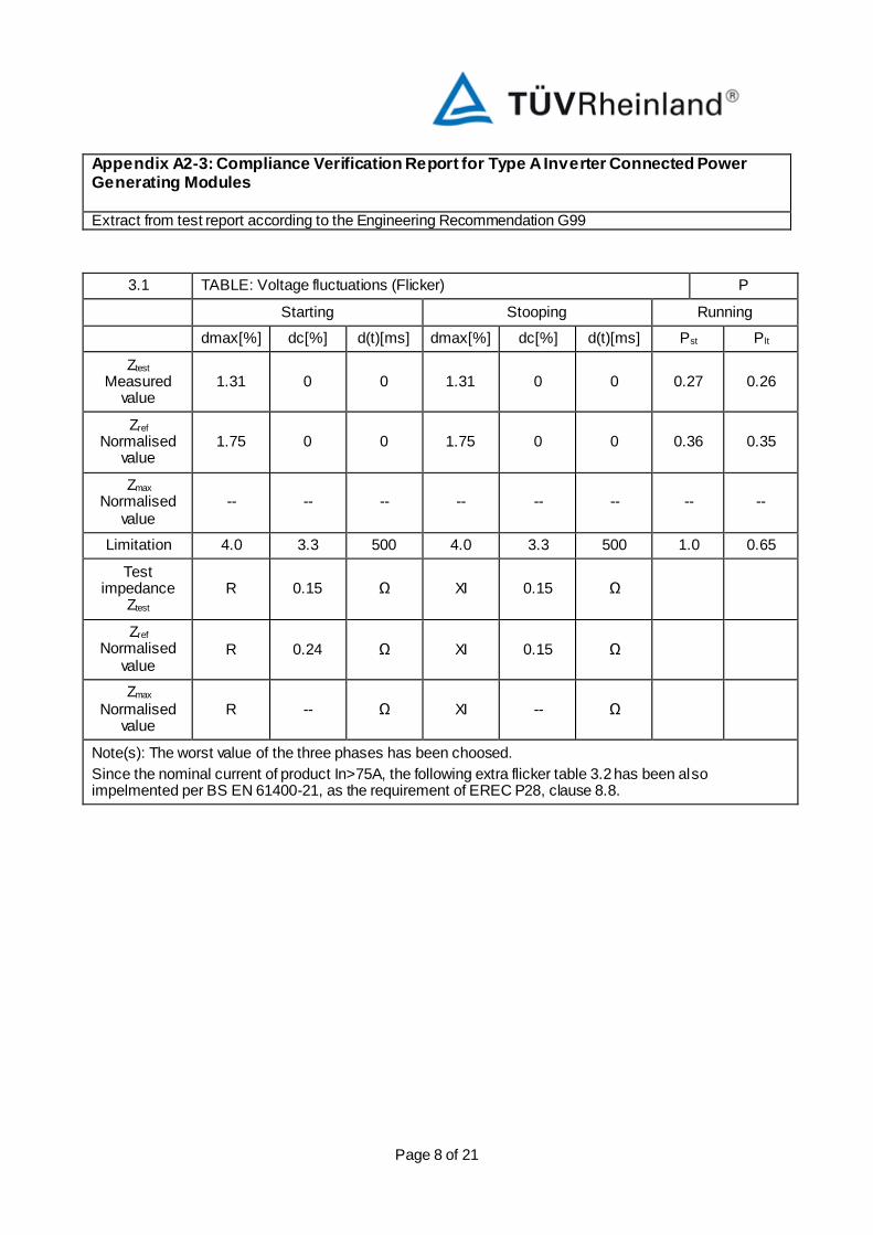
3.1 TABLE: Voltage fluctuations (Flicker) P
Starting Stooping Running
dmax[%] dc[%] d(t)[ms] dmax[%] dc[%] d(t)[ms] Pst Plt
Ztest
Measured value
1.31 0 0 1.31 0 0 0.27 0.26
Zref Normalised
value 1.75 0 0 1.75 0 0 0.36 0.35
Zmax Normalised
value -- -- -- -- -- -- -- --
Limitation 4.0 3.3 500 4.0 3.3 500 1.0 0.65
Test impedance
Ztest
R 0.15 Ω XI 0.15 Ω
Zref Normalised
value R 0.24 Ω XI 0.15 Ω
Zmax Normalised
value R -- Ω XI -- Ω
Note(s): The worst value of the three phases has been choosed.
Since the nominal current of product In>75A, the following extra flicker table 3.2 has been also impelmented per BS EN 61400-21, as the requirement of EREC P28, clause 8.8.

Appendix A2-3: Compliance Verification Report for Type A Inverter Connected Power Generating Modules Extract from test report according to the Engineering Recommendation G99
Page 9 of 21
3.2 TABLE: Voltage fluctuations (Flicker) per BS EN 61400-21
(Extra test other than form A2-3) P
30° impedance angle
Measurement P/Pn [%] Pst Cφk
1 10 0.02 0.43
2 20 0.03 0.53
3 30 0.03 0.52
4 40 0.03 0.51
5 50 0.03 0.54
6 60 0.03 0.52
7 70 0.03 0.56
8 80 0.03 0.55
9 90 0.03 0.53
10 100 0.03 0.65
11 100 0.02 0.49
12 100 0.02 0.40
50° impedance angle
Measurement P/Pn [%] Pst Cφk
1 10 0.02 0.35
2 20 0.02 0.43
3 30 0.02 0.43
4 40 0.02 0.43
5 50 0.02 0.45
6 60 0.02 0.44
7 70 0.02 0.47
8 80 0.02 0.46
9 90 0.02 0.45
10 100 0.03 0.54
11 100 0.02 0.42
12 100 0.02 0.36
70° impedance angle
Measurement P/Pn [%] Pst Cφk
1 10 0.01 0.26

Appendix A2-3: Compliance Verification Report for Type A Inverter Connected Power Generating Modules Extract from test report according to the Engineering Recommendation G99
Page 10 of 21
2 20 0.02 0.31
3 30 0.02 0.31
4 40 0.02 0.31
5 50 0.02 0.33
6 60 0.02 0.33
7 70 0.02 0.35
8 80 0.02 0.35
9 90 0.02 0.34
10 100 0.02 0.41
11 100 0.02 0.34
12 100 0.02 0.31
85° impedance angle
Measurement P/Pn [%] Pst Cφk
1 10 0.01 0.21
2 20 0.01 0.23
3 30 0.01 0.24
4 40 0.01 0.24
5 50 0.01 0.25
6 60 0.01 0.25
7 70 0.01 0.27
8 80 0.01 0.27
9 90 0.01 0.27
10 100 0.02 0.33
11 100 0.01 0.29
12 100 0.01 0.29
Note(s): Sk/Sn=20

Appendix A2-3: Compliance Verification Report for Type A Inverter Connected Power Generating Modules Extract from test report according to the Engineering Recommendation G99
Page 11 of 21
4 TABLE: DC Injection (Idc) P
Test Conditions Measurements Limit
Pn/Pn Idc / In [%]
Idc/In L1 L2 L3
10% 0.22 0.15 0.01 0.25%
55% 0.21 0.12 0.03 0.25%
100% 0.20 0.18 0.12 0.25%
Note(s):
5 TABLE: Power Factor P
Test Conditions Measurements Limit
P/Pn cosφ U/Un P [kW] Q [kVar] cosφ U [V] I [A] cosφ
100% 1.00 0.94 103.35 1.75 0.999 216.84 158.89 >0.95
100% 1.00 1.0 109.39 2.00 0.999 230.70 158.07 >0.95
100% 1.00 1.1 109.50 2.01 0.999 253.77 143.83 >0.95
Note(s):

Appendix A2-3: Compliance Verification Report for Type A Inverter Connected Power Generating Modules Extract from test report according to the Engineering Recommendation G99
Page 12 of 21
6 TABLE: Protection-Frequency tests (OF/UF) P
Condition Setting
[Hz]
Measurement Limitation
Trip value [Hz]
F>> 52.0 52.01
± 0.1% of fn F< 47.5 47.50
F<< 47 47.01
Condition Setting
[ms]
Measurement Limitation
Trip time
F>> 500 541.50 500-600
F< 20000 20070.00 20000-20100
F<< 500 533.00 500-600
Condition
Measurement limitation F
[Hz]
t [s]
47.7 30 No trip No trip
47.2 19.5 No trip No trip
46.8 0.45 No trip No trip
51.8 120 No trip No trip
52.2 0.45 No trip No trip
Note(s):

Appendix A2-3: Compliance Verification Report for Type A Inverter Connected Power Generating Modules Extract from test report according to the Engineering Recommendation G99
Page 13 of 21
7 TABLE: Protection-Voltage tests (OV/UV) P
Condition Setting [U/Un]
Measurement
Limitation Trip value [V]
L1 L2 L3 L123
U>> 1.19
(1.13*) 273.6 273.5 273.7 237.6
± 1% of Un U> 1.14
(1.10*) 262.2 262.2 262.4 262.3
U<< 0.80 183.8 184.0 183.9 183.9
Condition Setting
[ms]
Measurement
Limitation Trip time
L1 L2 L3 L123
U>> 500 582.00 519.00 530.50 532.5 500-600
U> 1000 1033.00 1022.00 1022.00 1022.00 1000-1100
U<< 2500 2537.00 2532.50 2537.50 2532.50 2500-2600
Condition
Measurement limitation U/Un
t [s]
0.82 5 No trip No trip
0.78 2.45 No trip No trip
1.12 5 No trip No trip
1.17 0.95 No trip No trip
1.20 0.45 No trip No trip
Note(s):*: settings for product connect with a non-standard transformer

Appendix A2-3: Compliance Verification Report for Type A Inverter Connected Power Generating Modules Extract from test report according to the Engineering Recommendation G99
Page 14 of 21
8.1 TABLE: Protection-Loss of mains test P
Power 100%
Input : 800 Vdc
Conditions PR [kW] QL [kVar] QC [kVar] Qf Trip time
[ms] Limitation
[ms]
PR: -10% QC: +10%
L1: 32.94 L1: 36.60 L1: 40.15 1.16
104 500 L2: 32.94 L2: 36.50 L2: 40.15 1.16
L3: 32.94 L3: 36.60 L3: 40.15 1.16
PR: -10% QC: +5%
L1: 32.94 L1: 36.60 L1: 38.43 1.14
134 500 L2: 32.94 L2: 36.50 L2: 38.33 1.14
L3: 32.94 L3: 36.60 L3: 38.43 1.14
PR: -10% QC: 0%
L1: 32.94 L1: 36.60 L1: 36.50 1.11
176 500 L2: 32.94 L2: 36.50 L2: 36.50 1.11
L3: 32.94 L3: 36.60 L3: 36.50 1.11
PR: -10% QC: -5%
L1: 32.94 L1: 36.60 L1: 34.68 1.08
154 500 L2: 32.94 L2: 36.50 L2: 34.68 1.08
L3: 32.94 L3: 36.60 L3: 34.68 1.08
PR: -10% QC: -10%
L1: 32.94 L1: 36.60 L1: 32.85 1.05
127 500 L2: 32.94 L2: 36.50 L2: 32.85 1.05
L3: 32.94 L3: 36.60 L3: 32.85 1.05
PR: -5% QC: +10%
L1: 34.77 L1: 36.60 L1: 40.15 1.10
114 500 L2: 34.77 L2: 36.50 L2: 40.15 1.10
L3: 34.77 L3: 36.60 L3: 40.15 1.10
PR: -5% QC: -10%
L1: 34.77 L1: 36.60 L1: 32.85 1.00
137 500 L2: 34.77 L2: 36.50 L2: 32.85 1.00
L3: 34.77 L3: 36.60 L3: 32.85 1.00
PR: 0% QC: +10%
L1: 36.60 L1: 36.60 L1: 40.15 1.05
140 500 L2: 36.60 L2: 36.50 L2: 40.15 1.05
L3: 36.60 L3: 36.60 L3: 40.15 1.05
PR: -5% QC: +5%
L1: 34.77 L1: 36.60 L1: 38.33 1.08
140 500 L2: 34.77 L2: 36.50 L2: 38.33 1.08
L3: 34.77 L3: 36.60 L3: 38.33 1.08
L1: 34.77 L1: 36.60 L1: 36.50 1.05 191

Appendix A2-3: Compliance Verification Report for Type A Inverter Connected Power Generating Modules Extract from test report according to the Engineering Recommendation G99
Page 15 of 21
PR: -5% QC: 0%
L2: 34.77 L2: 36.50 L2: 36.50 1.05 500
L3: 34.77 L3: 36.60 L3: 36.50 1.05
PR: -5% QC: -5%
L1: 34.77 L1: 36.60 L1: 34.68 1.02
176 500 L2: 34.77 L2: 36.50 L2: 34.68 1.02
L3: 34.77 L3: 36.60 L3: 34.68 1.02
PR: 0% QC: +5%
L1: 36.60 L1: 36.60 L1: 38.33 1.02
160 500 L2: 36.60 L2: 36.50 L2: 38.33 1.02
L3: 36.60 L3: 36.60 L3: 38.33 1.02
PR: 0% QC: 0%
L1: 36.60 L1: 36.60 L1: 36.50 1.00
212 500 L2: 36.60 L2: 36.50 L2: 36.50 1.00
L3: 36.60 L3: 36.60 L3: 36.50 1.00
PR: 0% QC: -5%
L1: 36.60 L1: 36.60 L1: 34.68 0.97
182 500 L2: 36.60 L2: 36.50 L2: 34.68 0.97
L3: 36.60 L3: 36.60 L3: 34.68 0.97
PR: +5% QC: +5%
L1: 38.43 L1: 36.60 L1: 38.33 0.97
144 500 L2: 38.43 L2: 36.50 L2: 38.33 0.97
L3: 38.43 L3: 36.60 L3: 38.33 0.97
PR: +5% QC: 0%
L1: 38.43 L1: 36.60 L1: 36.50 0.95
188 500 L2: 38.43 L2: 36.50 L2: 36.50 0.95
L3: 38.43 L3: 36.60 L3: 36.50 0.95
PR: +5% QC: -5%
L1: 38.43 L1: 36.60 L1: 34.68 0.93
163 500 L2: 38.43 L2: 36.50 L2: 34.68 0.93
L3: 38.43 L3: 36.60 L3: 34.68 0.93
PR: 0% QC: -10%
L1: 36.60 L1: 36.60 L1: 32.85 0.95
160 500 L2: 36.60 L2: 36.50 L2: 32.85 0.95
L3: 36.60 L3: 36.60 L3: 32.85 0.95
PR: +5% QC: +10%
L1: 38.43 L1: 36.60 L1: 40.15 1.00
107 500 L2: 38.43 L2: 36.50 L2: 40.15 1.00
L3: 38.43 L3: 36.60 L3: 40.15 1.00
PR: +5% QC: -10%
L1: 38.43 L1: 36.60 L1: 32.85 0.90
134 500 L2: 38.43 L2: 36.50 L2: 32.85 0.90
L3: 38.43 L3: 36.60 L3: 32.85 0.90
L1: 40.26 L1: 36.60 L1: 40.15 0.95 105

Appendix A2-3: Compliance Verification Report for Type A Inverter Connected Power Generating Modules Extract from test report according to the Engineering Recommendation G99
Page 16 of 21
PR: +10% QC: +10%
L2: 40.26 L2: 36.50 L2: 40.15 0.95 500
L3: 40.26 L3: 36.60 L3: 40.15 0.95
PR: +10% QC: +5%
L1: 40.26 L1: 36.60 L1: 38.33 0.93
136 500 L2: 40.26 L2: 36.50 L2: 38.33 0.93
L3: 40.26 L3: 36.60 L3: 38.33 0.93
PR: +10% QC: 0%
L1: 40.26 L1: 36.60 L1: 36.50 0.91
174 500 L2: 40.26 L2: 36.50 L2: 36.50 0.91
L3: 40.26 L3: 36.60 L3: 36.50 0.91
PR: +10% QC: -5%
L1: 40.26 L1: 36.60 L1: 34.68 0.88
148 500 L2: 40.26 L2: 36.50 L2: 34.68 0.88
L3: 40.26 L3: 36.60 L3: 34.68 0.88
PR: +10% QC: -10%
L1: 40.26 L1: 36.60 L1: 32.85 0.86
118 500 L2: 40.26 L2: 36.50 L2: 32.85 0.86
L3: 40.26 L3: 36.60 L3: 32.85 0.86
Power 66%
Input : 650 Vdc
Conditions PR [kW] QL [kVar] QC [kVar] Qf Trip time
[ms] Limitation
[ms]
PR: 0% QC: -5%
L1: 24.20 L1: 24.20 L1: 22.80 0.97
156 500 L2: 24.20 L2: 24.20 L2: 22.80 0.97
L3: 24.20 L3: 24.20 L3: 22.80 0.97
PR: 0% QC: -4%
L1: 24.20 L1: 24.20 L1: 23.04 0.98
159 500 L2: 24.20 L2: 24.20 L2: 23.04 0.98
L3: 24.20 L3: 24.20 L3: 23.04 0.98
PR: 0% QC: -3%
L1: 24.20 L1: 24.20 L1: 23.28 0.98
164 500 L2: 24.20 L2: 24.20 L2: 23.28 0.98
L3: 24.20 L3: 24.20 L3: 23.28 0.98
PR: 0% QC: -2%
L1: 24.20 L1: 24.20 L1: 23.52 0.99
168 500 L2: 24.20 L2: 24.20 L2: 23.52 0.99
L3: 24.20 L3: 24.20 L3: 23.52 0.99
PR: 0% QC: -1%
L1: 24.20 L1: 24.20 L1: 23.76 0.99
191 500 L2: 24.20 L2: 24.20 L2: 23.76 0.99
L3: 24.20 L3: 24.20 L3: 23.76 0.99

Appendix A2-3: Compliance Verification Report for Type A Inverter Connected Power Generating Modules Extract from test report according to the Engineering Recommendation G99
Page 17 of 21
PR: 0% QC: 0%
L1: 24.20 L1: 24.20 L1: 24.00 1.00
264 500 L2: 24.20 L2: 24.20 L2: 24.00 1.00
L3: 24.20 L3: 24.20 L3: 24.00 1.00
PR: 0% QC: +1%
L1: 24.20 L1: 24.20 L1: 24.24 1.00
208 500 L2: 24.20 L2: 24.20 L2: 24.24 1.00
L3: 24.20 L3: 24.20 L3: 24.24 1.00
PR: 0% QC: +2%
L1: 24.20 L1: 24.20 L1: 24.48 1.01
193 500 L2: 24.20 L2: 24.20 L2: 24.48 1.01
L3: 24.20 L3: 24.20 L3: 24.48 1.01
PR: 0% QC: +3%
L1: 24.20 L1: 24.20 L1: 24.72 1.01
171 500 L2: 24.20 L2: 24.20 L2: 24.72 1.01
L3: 24.20 L3: 24.20 L3: 24.72 1.01
PR: 0% QC: +4%
L1: 24.20 L1: 24.20 L1: 24.96 1.02
156 500 L2: 24.20 L2: 24.20 L2: 24.96 1.02
L3: 24.20 L3: 24.20 L3: 24.96 1.02
PR: 0% QC: +5%
L1: 24.20 L1: 24.20 L1: 25.20 1.02
148 500 L2: 24.20 L2: 24.20 L2: 25.20 1.02
L3: 24.20 L3: 24.20 L3: 25.20 1.02
Power 33%
Input : 550 Vdc
Conditions PR [kW] QL [kVar] QC [kVar] Qf Trip time
[ms] Limitation
[ms]
PR: 0% QC: -5%
L1: 12.10 L1: 12.10 L1: 11.50 0.97
103 500 L2: 12.10 L2: 12.10 L2: 11.40 0.97
L3: 12.00 L3: 12.00 L3: 11.50 0.98
PR: 0% QC: -4%
L1: 12.10 L1: 12.10 L1: 11.62 0.98
111 500 L2: 12.10 L2: 12.10 L2: 11.52 0.98
L3: 12.00 L3: 12.00 L3: 11.62 0.98
PR: 0% QC: -3%
L1: 12.10 L1: 12.10 L1: 11.74 0.98
126 500 L2: 12.10 L2: 12.10 L2: 11.64 0.98
L3: 12.00 L3: 12.00 L3: 11.74 0.99
PR: 0% QC: -2%
L1: 12.10 L1: 12.10 L1: 11.86 0.99
138 500 L2: 12.10 L2: 12.10 L2: 11.76 0.99
L3: 12.00 L3: 12.00 L3: 11.86 0.99

Appendix A2-3: Compliance Verification Report for Type A Inverter Connected Power Generating Modules Extract from test report according to the Engineering Recommendation G99
Page 18 of 21
PR: 0% QC: -1%
L1: 12.10 L1: 12.10 L1: 11.98 0.99
182 500 L2: 12.10 L2: 12.10 L2: 11.88 0.99
L3: 12.00 L3: 12.00 L3: 11.98 1.00
PR: 0% QC: 0%
L1: 12.10 L1: 12.10 L1: 12.10 1.00
250 500 L2: 12.10 L2: 12.10 L2: 12.00 1.00
L3: 12.00 L3: 12.00 L3: 12.10 1.00
PR: 0% QC: +1%
L1: 12.10 L1: 12.10 L1: 12.22 1.00
235 500 L2: 12.10 L2: 12.10 L2: 12.12 1.00
L3: 12.00 L3: 12.00 L3: 12.22 1.01
PR: 0% QC: +2%
L1: 12.10 L1: 12.10 L1: 12.34 1.01
154 500 L2: 12.10 L2: 12.10 L2: 12.24 1.01
L3: 12.00 L3: 12.00 L3: 12.34 1.01
PR: 0% QC: +3%
L1: 12.10 L1: 12.10 L1: 12.46 1.01
128 500 L2: 12.10 L2: 12.10 L2: 12.36 1.01
L3: 12.00 L3: 12.00 L3: 12.46 1.02
PR: 0% QC: +4%
L1: 12.10 L1: 12.10 L1: 12.58 1.02
118 500 L2: 12.10 L2: 12.10 L2: 12.48 1.02
L3: 12.00 L3: 12.00 L3: 12.58 1.02
PR: 0% QC: +5%
L1: 12.10 L1: 12.10 L1: 12.71 1.02
108 500 L2: 12.10 L2: 12.10 L2: 12.60 1.02
L3: 12.00 L3: 12.00 L3: 12.71 1.03
Note(s):
8.2 TABLE: Vector shift stability test P
Test Condition Measurement Limit
49.5Hz, +50degree No trip No trip
50.5Hz, -50degree No trip No trip

Appendix A2-3: Compliance Verification Report for Type A Inverter Connected Power Generating Modules Extract from test report according to the Engineering Recommendation G99
Page 19 of 21
8.3 TABLE: RoCoF stability test P
Test Condition Measurement Limit
49Hz->51Hz + 0.95 Hz/s
No trip No trip
51Hz->49Hz - 0.95 Hz/s
No trip No trip
9.1 TABLE: Limitest frequency sensitive mode-over frequency (LFSM-O) P
Test No. 1
Test Conditions
Measurements Target value
∆ Limitation
f [Hz]
P/Pn [%]
f [Hz]
Trise [s]
Tsettling [s]
Tv [s]
P/Pn [%]
∆ P/Pn [%]
∆ P/Pn [%]
T [s]
Tv [s]
a) 50 99.69 50.00 -- -- -- 100 -0.31
≤± 10 ≤10 ≤2
b) 50.45 98.34 50.45 1.2 1.2 0.2 99 -0.65
c) 50.7 93.20 50.70 6.0 6.0 0.2 94 -0.80
d) 51.15 83.93 51.15 1.2 1.2 0.1 83 0.93
e) 50.7 93.20 50.70 1.0 1.0 0.1 94 -0.80
f) 50.45 97.98 50.45 1.2 1.2 0.1 99 -1.02
g) 50 99.32 50.00 2.4 2.4 0.1 100 -0.68
Test No. 2
Test Conditions
Measurements Target value
∆ Limitation
f [Hz]
P/Pn [%]
f [Hz]
Trise [s]
Tsettling [s]
Tv [s]
P/Pn [%]
∆ P/Pn [%]
∆ P/Pn [%]
T [s]
Tv [s]
a) 50 49.74 50.00 -- -- -- 50 -0.26
≤± 10
≤10 ≤2
b) 50.45 48.35 50.45 5.7 5.7 0.6 49 -0.64
c) 50.7 43.41 50.70 0.6 0.6 0.2 44 -0.58
d) 51.15 34.50 51.15 0.6 0.6 0.1 33 1.50
e) 50.7 43.33 50.7 5.8 5.8 0.1 44 -0.66
f) 50.45 48.25 50.45 3.6 3.6 0.1 49 -0.74
g) 50 49.99 50.00 1.8 1.8 0.1 50 -0.01
Note(s):
P(f) curve setting for test: f1: 50.4Hz; fstop: 50.4Hz (Deactivated); Droop: 10%
Appendix A2-3: Compliance Verification Report for Type A Inverter Connected Power Generating Modules Extract from test report according to the Engineering Recommendation G99
Page 20 of 21
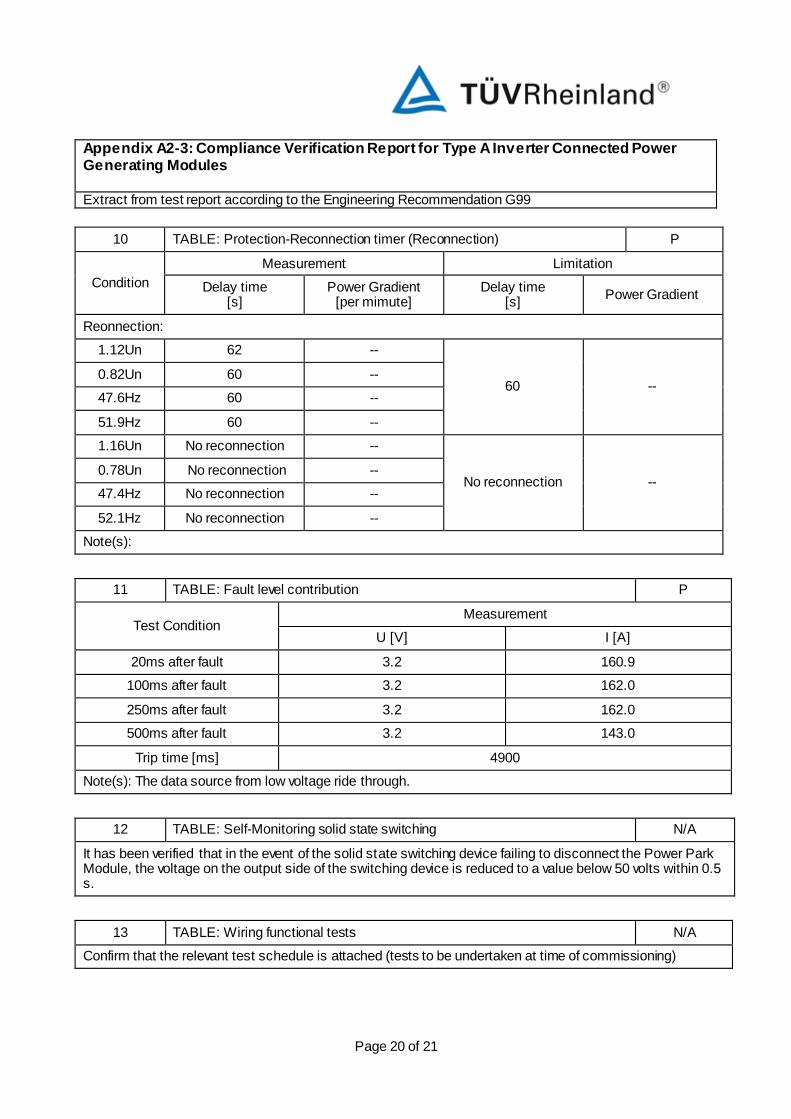
10 TABLE: Protection-Reconnection timer (Reconnection) P
Condition
Measurement Limitation
Delay time [s]
Power Gradient [per mimute]
Delay time [s]
Power Gradient
Reonnection:
1.12Un 62 --
60 -- 0.82Un 60 --
47.6Hz 60 --
51.9Hz 60 --
1.16Un No reconnection --
No reconnection -- 0.78Un No reconnection --
47.4Hz No reconnection --
52.1Hz No reconnection --
Note(s):
11 TABLE: Fault level contribution P
Test Condition Measurement
U [V] I [A]
20ms after fault 3.2 160.9
100ms after fault 3.2 162.0
250ms after fault 3.2 162.0
500ms after fault 3.2 143.0
Trip time [ms] 4900
Note(s): The data source from low voltage ride through.
12 TABLE: Self-Monitoring solid state switching N/A
It has been verified that in the event of the solid state switching device failing to disconnect the Power Park Module, the voltage on the output side of the switching device is reduced to a value below 50 volts within 0.5 s.
13 TABLE: Wiring functional tests N/A
Confirm that the relevant test schedule is attached (tests to be undertaken at time of commissioning)

Appendix A2-3: Compliance Verification Report for Type A Inverter Connected Power Generating Modules Extract from test report according to the Engineering Recommendation G99
Page 21 of 21
14 TABLE: Logic interface (input port). P
Confirm that an input port is provided and can be used to shut down the module.