Embed Size (px)
Citation preview
Appendix AUse Case Modeling for Smart Grids Accordingto IECPAS 62559
Introduction to Use Case Modeling for Smart Grids
This chapter is based on both a project and a report the authors have prepared forthe German DKE The following aspects and requirements have been discussed anddeveloped in German national standardization and are envisioned to be brought intothe M490 mandate of the EC and the IEC SG 3 work
Use cases were originally established for the purpose of identifying how a systembehaves in relation to stakeholders For CIM-based communications the establish-ment of use cases is to document future scenarios of energy management systemsA uniform and structured documentation also provides a basis for communicationbetween actors involved in system development and the analysis of the use casespermits deduction of requirements for system development Starting with the re-quirements defined the conceptual design of data models interfaces exchange pro-cesses and protocols can take place afterwards As the result of these efforts theartifacts identified are to be studied with regard to their need for standardization andinvolvement in the standardization process
With a sound base of use cases which cover large portions of the future energysystems that are relevant to standardization and with the resulting requirementsa basis for the design of interoperable technical solutions is created Standardiz-ing these solution concepts finally contributes to the establishment of a standards-based open and interoperable architecture for a future energy system in which so-lutions from various manufacturers jointly implement the vision of a smart grid
Alongside general use cases relevant to standardization as are described heredetailed use cases specific to individual companies and relevant to competition arenecessary within those companies to enable them to develop solutions and sell themon the market The recommendations presented in this annex are also with somelimitations applicable to the description and management of company-specific usecases The objective must be to support linking the two types of use cases in thelong term in order to enable companies to analyze their use cases in relation torelevant standards and thus promote standardization work and the development ofinteroperable technical solutions
188 A Use Case Modeling for Smart Grids According to IECPAS 62559
This appendix initially describes requirements for the compilation of use casesand presents recommendations in that regard Then on the basis of IECPAS 62559a strategy for use case compilation is described and a template for use case com-pilation is outlined For careful description and handling of various use cases aclassification system and conventions intended to support the process of use caseidentification are presented followed by a five stage process for compilation andprocessing of use cases In addition the embedding of use cases in internationalstandardization is outlined
Requirements for Use Case Descriptions for the Smart Grid
Due to the complexity of the smart grid and especially because of the large varietyof both actors and systems use case descriptions are to be used to create a commonunderstanding for the development and identification of interfaces and data modelsIn this context use case descriptions are to be established for various target groupssuch as
bull companies in the energy industrybull IT manufacturersbull equipment manufacturersbull standardization organizationsbull legislators andbull companies from other sectors than the energy industry
This implies that use case descriptions for such an extensive group of stakehold-ers can only be established involving several participants with different backgroundknowledge and viewpoints Use case descriptions represent the central element forthe description of requirements and the general functionality of systems and theyare to support cooperation between various experts (eg electrical engineers and ITexperts) sectors of industry organizations and committees Furthermore use casesform the basis of further standardization work and the design of interoperabilityand conformance tests As a result of the complexity involved clear methodologyand classification and corresponding support by software tools and tool chains is re-quired National use case descriptions are also to be used to compile correspondingprofiles for standards with the aim of refining international standards for use for ex-ample in Germany in relation to German regulatory requirements In this contextthe various levels of national and international standardization and the associateddocuments are to be observed
In order to facilitate management of a large number of use case descriptions pos-sibly compiled by different persons with highly differing backgrounds a structureduniform description is necessary if consistent and structurally similar descriptionsare to be created A high level of quality and the opportunity to locate and retrieveuse cases are required if the effort involved in their documentation is to be justified
To provide for contributions to international standardization and to avoid addi-tional consequential costs it is advisable to present and discuss methods and model
A Use Case Modeling for Smart Grids According to IECPAS 62559 189
procedures for the compilation of use case descriptions in the various standardiza-tion organizations on the international level and canvass for their acceptance This isaddress eg by the Use Cases and Sustainable processes team for the SG-CG M490mandate in Europe User-friendliness of the methods is required as are reasonabletime and costs for compilation of the descriptions especially as far as the compilerrsquostime and the costs of the tools (TCO) are concerned
From a technical point of view the compilation of use cases is to be regardedas a collaborative task In this respect functionalities for multiple user operationand systems for the locking commenting release revision tracking and versionmanagement of use cases are to be provided In addition further aspects such asmultilingual capability could be of interest for using use cases and systems in inter-national standardization and projects
The large number of use cases to be expected gives rise to the following require-ments
bull Organization systems Provision of functionalities for classification groupingsearching and navigation of use case descriptions
bull Consistency In this regard the objectives are to ensure uniform semantics andavoid redundancies Both of these could for example be achieved by using acomprehensive model It is also to be ensured that the descriptions are complete
Ideally the entire process of use case compilation should be supported from startto finish by a single integrated tool As this usually can only be implemented atconsiderable cost import and export from and to other applications should be sup-ported
General Recommendations on Use Case Compilation andManagement
Compiling updating and managing use cases is complex especially with a largenumber of use cases In this context a suitable scope and the degree of detail arefirst to be specified and the descriptions limited With regard to the requirementsdescribed in the previous section the time and cost of compilation are to be mini-mized and the process is to be supported by software It must be taken into accountthat apart from the initial compilation of use cases further use cases will have tobe added and existing use cases adjusted With regard to the maintenance of the usecase collection suitable criteria for classification have to be established Attentionhas to be paid here to ensuring a relatively long-term applicability (resistance tochange) of the criteria so as to avoid regular reclassification
In order to master the challenges associated with the compilation and manage-ment of use cases it is recommended that the process be structured by implementa-tion of the following measures
bull Use of conventions Guidelines for example of naming conventions and partic-ular UML diagrams for the presentation of graphic representations of the real-world
190 A Use Case Modeling for Smart Grids According to IECPAS 62559
bull Limitation to the essentials Avoidance of redundancies for example and reduc-tion to relevant information only
bull Use of familiarproven methodsapproaches Eg relying on familiarprovenmodeling languages such as UML
bull Tool support Use of software tools to reduce manual work especially for qualityand consistency assurance
In addition the following procedure is proposed for the establishment of a strat-egy for use case compilation It is strongly advisable to take previous related ap-proaches such as the following into account
bull German Standardization Roadmap [12] in particular with its classification ofstandards
bull IECPAS 62559 IntelliGrid Methodology for Developing Requirements for En-ergy Systems [54] This publication supplies a methodology with correspondingtemplates for the identification of requirements and description of use cases andis to be adapted and refined with regard to national needs
bull Established approaches from academic research and practice In this context arti-facts methods and procedures are to be examined for example reference modelsfrom the power sector the catalogue of reference models for the energy indus-try (Energy-RMC) [22] (with regard to structuring) NIST [92] (domains) TampDEurope (overview) [16] Smart Grid
Additionally there is the opportunity for an exchange of information with other(standardization) organizations which are also dealing with the compilation of usecases for smart grids for example to draw upon the work of the FG Smart group atITU-T (International Telecommunication Union Standardization Sector)
Furthermore to order and facilitate retrieval of the use case descriptions a classi-fication of use cases should be established See the section entitled Organization andclassification of use cases In order to ensure a unified description of use cases byseveral editors it is proposed that a template for use case writing be established andseveral templates may possibly be required for different types of editors (eg man-agers energy experts IT experts standardization experts or legislators) In generalthe envisaged process of use case compilation and application has to be taken intoaccount as this should have corresponding effects on the nature of the classificationcriteria and templates
The concepts templates and classification criteria then established will certainlyrequire iterative continuous elaboration and adjustment The adjustments requiredwill in the authorsrsquo experience predominantly become obvious in the course ofactual practical use Provision is to be made in advance for revisions to these cen-tral documents These should preferably take place in the background so as not toimpede the use case compilers
Strategy for Use Case Compilation
A number of conventions and guidelines are to be considered especially if the man-agement and use of various use cases from different authors and sources are to take
A Use Case Modeling for Smart Grids According to IECPAS 62559 191
place consistently A conceptual description of central components in use case com-pilation is presented below
The description of use cases is fundamentally to take place on the basis of IEC-PAS 62559 [54] In addition the use of a central repository for a general templateand various role-specific templates is recommended - for both enterprise and stan-dardization use The additions to IECPAS 62559 [54] are described in brief below
bull Central repository Here at a central location various descriptions of for in-stance definitions actors conventions and relevant documents are to be storedThese elements are to be accessed and used accordingly during the compilationof use case descriptions
bull General template for use cases This constitutes a complex internal templatewhich contains all the relevant attributes for all roles involved For simplicity ssake it is advisable to confront only use case experts and equivalent administra-tors with the general template A role-specific template should be provided fornormal use case compilers (see next point)
bull Role-specific templates for use cases Due to the complexity of use case compi-lation specific templates should be established for each role and made availablespecifically to the various roles such as managers energy experts IT experts oreditorsuse case managers Clarity for the use case compilers is ensured by theuse of role-specific templates
The structure of the central repository and that of the general template are roughlydescribed below and the additions to IECPAS 62559 are presented
Central Repository
The structure of the central repository is presented below with the (German DKE)additions to the existing IECPAS 62559 accented in bold type
bull Global Repository
ndash Glossarymiddot Terms List of Roles (market roles system roles) Actors List Acronyms
ndash Information Exchangemiddot Data Objects Data Protection Class Characteristics of Information Ex-
changesndash Structuring
middot Domains (spheres of action) General Use Case Scenarios High-levelFunctions Classification Criteria for Use Cases Views for Use Cases
ndash Documentsmiddot Resources
ndash Methodologymiddot Used Concepts Conventions Used Verbs
ndash Processmiddot Used roles within Use Case creation Approval Status
192 A Use Case Modeling for Smart Grids According to IECPAS 62559
Template for Use Case Compilation
The structure of the use case template is described below with the additions toIECPAS 62559 accented in bold type The template is structured in two parts ageneral part which contains attributes for rough description and a details part whichsupplements the former with more specific information especially with regard to IT
General1 Description of the User Requirements of a Function11 Domain ExpertsArea of Expertise Change Description Approval Status VersionDate12 Name of Function + ID and Naming conventionsShort description (executive summary)13 Scope and Objectives of Function14 Narrative of Function + optional Diagram in UML15 Actors People Systems Applications Databases Power Systemother Stakeholder + Market role and type of interaction16 Legal Issues Contracts Regulations Policies and Constraints +Restriction Type ReferenceFurther Constraints consideration of standards apart from legaldocuments17 Preconditions and Assumptions Post conditions and Events +Events High-level functionsClassification + support selection identification of Use CasesNotes + comments2 Drawing or Diagram of Function + textual description
Details3 Step by Step Analysis of FunctionID and name of activityShort description of activity31 Preconditions Assumptions Post conditions and events (see gen-eral)32 Steps - Normal SequenceConfiguration Quality of Service (QoS) Security Data ManagementConstraints and other (catch all) + Selection of information entriesfrom repository33 Steps- Alternative Error Management and or Maintenance Backup SequencesNotes (comments)
A Use Case Modeling for Smart Grids According to IECPAS 62559 193
Further ConventionsRequirementsGuidelines
It is to be ensured in the compilation of use cases that terms are used consistentlyand in a uniform manner This particularly concerns the following entities but is notlimited to them
bull Actorsbull Rolesbull Classification criteriabull Structuring elementsbull Elements of the reference architecture
It is recommended to use established and accepted terms rather than definingnew terms When new previously non-existent terms are used it is advisable tosubmit an application for acceptance of the terms to a use case manager who candecide on the adoption of the new term or can identify an existing term with anequivalent meaning which should be used in its place Decisions on the adoptionof individual terms should not be taken by individuals but rather by consensus ofseveral responsible persons to ensure an as intersubjective acceptance as possible
To increase their comprehensibility and acceptance use cases should be de-scribed in such a way that the description is as general and neutral as possible withregard to for example technologies products companies or projects This pointapplies above all to the terms used in the description for which terms establishedin the community (if available) should always be preferred to terms which are spe-cific to companies groups or projects With regard to international acceptance it isadvisable to follow the guidelines of the IEC
Furthermore the stipulation of modeling languages and diagram types is to berecommended so as to arrive at a uniform description with which among otherfactors easier and more rapid understanding by all those involved can be achieved Itmay be possible to disregard the rules and conventions in order to remove obstaclesin the compilation of use cases and to accelerate their initial creation but compliancewith those rules and conventions should be ensured by subsequent revision
Organization and Classification of Use Cases
The organization and classification of use cases are important aspects enhancing thebenefits of use case compilation especially when there is a large number of usecases
In this context a distinction is to be made between the structuring of use caseson the one hand which supports navigation and provides easy access to use casesfor potential users and classification criteria on the other hand which are predomi-nantly intended to facilitate the identification of use cases
194 A Use Case Modeling for Smart Grids According to IECPAS 62559
With regard to structuring as in a tree diagram the following hierarchy isproposed
bull Use case scenarios
ndash Main function groupsmiddot Use case
middot Activities
In this regard a use case is only to be assigned to one domain while in contrastuse case scenarios are to provide a cross-domain ordering characteristic
The establishment of a structure or hierarchy can however only be usefully begunwhen several use cases have been compiled In this respect it is to be ensured that thesame degree of detail is maintained on each level wherever possible An adjustmentof the hierarchy will most probably become necessary in the course of time
Process for General Use Case Compilation and Processing
The process of use case compilation up to elaboration for standardization purposesis divided into five phases which are described in more detail below An overview ofthis process is shown in Figure A1 The energy and IT experts perform the draftingof the use case based on practical experience in several steps A core team includingin particular a use case manager provides the necessary conventions and guidelinesand essentially performs an overall consistency and quality assurance function to-gether with editing of the use case and incorporating it in standardization Finallyusers can search for and identify the classified use cases which are relevant to theirconcerns
A more detailed description of the individual roles their requirements and func-tions is presented in the next section followed by a closer description of the indi-vidual phases of the process
Roles in the Process of Use Case Compilation and Processing
In the following rough description of the roles involved in use case compilationsimplified distinctions are made between energy and IT experts and the core teamFurthermore only a roughly outlined process is considered in the course of thisannex and the guidelines of the IEC have to be taken into account in further elabo-ration
bull Energy expert Energy experts possess far-reaching expertise in a particular dis-cipline and contribute substantive information to the use case They identify newuse cases and initiate use case compilation
bull IT expert IT experts possess technical expertise above all in the ICT environ-ment and as a rule only general high-level knowledge of the energy field Theyprovide technical details for the use case and can estimate its feasibility in ICTterms
A Use Case Modeling for Smart Grids According to IECPAS 62559 195
Fig A1 Process for use case compilation and processing
bull Core team The core team is composed of various experts with broad expertisecovering a wide range of disciplines and is entrusted with use case compilationand the conventions involved With their knowledge of the domain they are re-sponsible for assuring the quality of the contents and can assess the relevance ofuse cases On account of their broad professional expertise spanning several ar-eas of application they can classify the use case in a holistic context (assigning itfor instance to a professional domain model or a reference architecture) Thereis at least one specific person in the core team who heads the team as the use casemanager and communicates its decisions
Above and beyond this the core team includes standardization experts Theseexperts have outstanding knowledge of established standards and current standard-ization projects in various standardization organizations and can assess and classifythe relevance of new approaches in this field Furthermore they are familiar withthe conventions and processes for submission of proposals to standardization or-ganizations The core team is assisted by use case administrators in the technicalmaintenance of the use case collection Support from further persons eg methodsexperts is also conceivable
196 A Use Case Modeling for Smart Grids According to IECPAS 62559
Phase 0 Conventions and Guidelines
Objective In this phase conventions and guidelines which are to govern the usecase compilation are established
Procedure The elaboration of conventions and guidelines with regard to use casecompilation and management takes place within the core team This comprises forexample a uniformly structured template for use cases for various stakeholders thestructure of the central repository classification of the use cases and guidelines forinstance with regard to graphical notations to be used Recommendations on theconventions and guidelines and the motivation behind them have already been de-scribed in the previous sections
Actors involved Core team
Information required Related approaches target groups
Results Conventions and guidelines for the use cases
Phase 1 Compilation
Objective An initial version of the use case which comprehensibly describes theplanned use of a system and the stakeholders involved on a technical level is createdin this phase In addition the quality of the content of the use case its thematic rel-evance to existing use cases and lack of overlaps with them are to be ensured
Procedure Compilation or contribution of the initial use case is normally carriedout by parties interested in standardization of various aspects of the use case andmust be performed in accordance with IECPAS 62559 andor the specific additionsbased upon it (cf section entitled Template for use case compilation)
This first version of the use case is established by energy experts who identifythe aims of the actors which are to be achieved by the use case The energy expertdescribes the use case on the basis of a concrete example (ideally motivated by cir-cumstances in practice) which should be kept as easily comprehensible as possibleThe use case outline (step 1a) created up to this point is proposed to the core teamwhich conducts a review and decides on the adoption and therefore further elabora-tion of the use case (step 1b) In this process the thematic relevance of the use casein the context of the objective is examined and use cases with the same content areidentified (with support by a software tool where appropriate) Should the aim dealtwith by the use case be considered irrelevant or should use cases with the sameor similar content exist the use case managers can reject the use case or requiresharpening up of the topic
If the response of the core team is favorable the use case is further elaboratedon a technical basis This comprises the identification of the actors involved in theuse case and their unequivocal definition (if they are not as yet generally known)
A Use Case Modeling for Smart Grids According to IECPAS 62559 197
Furthermore restrictions (requirements) and references under which the use casetakes place and conditions and assumptions which must be fulfilled before the usecase is performed are defined
Actors involved Energy experts core team
Information required Concrete use case with need for technical support list ofdefined actors central repository
Results Technical part of the use case (aims of the system description of the usecase actors involved restrictions and requirements conditions and assumptions)
Phase 2 Review and Consolidation
Objective In the consolidation phase the terminology used and compliance withconventions etc are reviewed and amendments or additions made as necessary Fi-nally a classification of the use case and its location in the overall context take placeso that efficient evaluation and identification are possible
Procedure The terminology conventions etc used in the technical part of the usecase are reviewed and if necessary adjusted for conformity with the specified termi-nology Terms not yet available in the central repository which represent essentialnew concepts in the use case can be included in the central repository if required
The use case is then enhanced as required with diagrams as stipulated (eg par-ticular UML diagrams - see also [17]) and existing non-conforming diagrams areconverted into a form which complies with the guidelines This is intended to ensurethe consistency of graphical notations throughout the collection of use cases and tocontribute to ease of understanding for the readers
Furthermore possible references to laws or regulations and to standards and cor-responding working groups which are relevant in the context of the use case areadded at this stage
The core team in its role of dealing with cross-cutting issues then finally classi-fies the use case on the basis of specified classification criteria (cf section entitledOrganization and classification of use cases)
Actors involved Core teamInformation required Initial version of the use case from energy experts centralrepository list of actorsResults Revised version of the technical part of the use case (adjusted terminologyreferences classification)
198 A Use Case Modeling for Smart Grids According to IECPAS 62559
Phase 3 Detailing
Objective Addition of further details and workflows to the use case
Procedure The use case developed up to this point is provided with further detailin this phase This is done by IT experts who further refine the use case by addingand describing activities These activities represent the individual steps of the usecase which have to be performed in a defined sequence to achieve the intended aim
Over and above this alternative sequences of the activities which may for exam-ple occur in the event of a fault are also identified in this phase Conditions andassumptions which are essential for the performance of the activity are also definedfor the individual steps The identification of the individual steps and alternative se-quences may result in the necessity of introducing further steps and so this detailingphase may have to be repeated leading to an incremental refinement of the use case
Actors involved IT experts
Information required Accepted revised version of the use case from the use casemanagers central repository list of actors
Results Detailed version of the use case (description of the individual activities inthe use case)
Phase 4 Finalization and Release
Objective Review of the use case and decision on further processing or release togo forward into standardization or for preparation for standardization and for theinterested professional public
Procedure The use case now detailed is reviewed by the core team in this phasewith regard to completeness and once again for compliance with conventions Theterminology conventions etc used are checked and if necessary adjusted for confor-mity with the specified terminology Terms not yet available in the central repositorywhich represent essential new concepts in the use case can be included in the centralrepository if required
The use case is enhanced as required with diagrams as stipulated (eg particularUML diagrams) and existing non-conforming diagrams are converted into a formwhich complies with the guidelines This is intended to ensure the consistency ofgraphical notations throughout the collection of use cases and to contribute to easeof understanding for the readers
Furthermore possible references to laws or regulations and to standards and cor-responding working groups which are relevant in the context of the activities in theuse case are added at this stage
Finally the use case is released by the use case managers for the further stan-dardization process or the preparation process for standardization or the use case is
A Use Case Modeling for Smart Grids According to IECPAS 62559 199
sent back for further processing (phase 3) so as to arrange for any changes by theIT experts
Actors involved Core team (especially use case manager)
Information required Detailed version of the use case from the IT experts centralrepository list of actors
Results Final version of the use case for the further standardization processes
Phase 5 Preparation for StandardizationUseIdentification
Objective Extension of a use case for the relevant standardization organizationand subsequent use for implementation Additionally identification of describeduse cases
Procedure From the finalized use cases and from any solutions which have alreadybeen developed by the energy and IT experts the core team identifies parts to bestandardized from which corresponding conceptual designs (eg for data modelinginterfaces etc) are derived or parts to be standardized are proposed by energy andIT experts
The standardization expert is given the task to prepare these IT parts and relevantparts of the use case and technical solution concept resulting from the requirementsdocumented for a specific standardization organization The use case is then pre-pared in accordance with the requirements of the standardization organization andgoes forward into the further standardization process
Users of the use cases can locate use cases relevant to them on the basis of theclassification and use or implement the use cases andor the resulting standards
In the context of further use of standards ranging up to implementation the sub-sequent compilation of dedicated test use cases and standard profiles is conceivableThese are to be appropriately detailed to permit technical implementation or testingfor interoperability where necessary
Actors involved Core team (especially standardization expert) energy and IT ex-perts use case users Information required Final version of the use case from thecore team standardization organization to which the use case is to be submittedand organizations requirements for use cases
Results Version of the use case prepared for the relevant standardization organiza-tion
Appendix BBasic Message Structure in XML Schema
Listing B1 Basic message structure in XML Schema
ltxml version=10 encoding=utf-8gtlt-- Common Message Specification for ESB Integration via IEC 61968 --gtltxsschema xmlns=httpwwwiecchTC572008schemamessagexmlnsxs=httpwwww3org2001XMLSchematargetNamespace=httpwwwiecchTC572008schemamessageelementFormDefault=qualified attributeFormDefault=unqualifiedversion=100gt
ltxscomplexType name=RequestTypegtltxsannotationgt
ltxsdocumentationgtRequest type definitionltxsdocumentationgtltxsannotationgtltxssequencegt
ltxsannotationgtltxsdocumentationgtRequest package is typically used tosupply parameters for rsquogetrsquo requestsltxsdocumentationgt
ltxsannotationgtltxselement name=StartTime type=xsdateTimeminOccurs=0gt
ltxsannotationgtltxsdocumentationgtStart time ofinterestltxsdocumentationgt
ltxsannotationgtltxselementgtltxselement name=EndTime type=xsdateTime minOccurs=0gt
ltxsannotationgtltxsdocumentationgtEnd time of interestltxsdocumentationgt
ltxsannotationgtltxselementgtltxselement name=Option type=xsstring minOccurs=0maxOccurs=unboundedgt
ltxsannotationgtltxsdocumentationgtRequest typespecializationltxsdocumentationgt
ltxsannotationgtltxselementgtltxselement name=ID type=xsstring minOccurs=0maxOccurs=unboundedgt
ltxsannotationgtltxsdocumentationgtObject ID forrequestltxsdocumentationgt
ltxsannotationgtltxselementgtltxsany namespace=other processContents=lax
202 B Basic Message Structure in XML Schema
minOccurs=0 maxOccurs=unboundedgtltxsannotationgt
ltxsdocumentationgtThis can be a CIM profile defined as anXSD with a CIM-specific namespaceltxsdocumentationgt
ltxsannotationgtltxsanygt
ltxssequencegtltxscomplexTypegtltxscomplexType name=ReplyTypegtltxsannotationgt
ltxsdocumentationgtReply type definitionltxsdocumentationgtltxsannotationgtltxssequencegt
ltxsannotationgtltxsdocumentationgtReply package is used to confirm successor report errorsltxsdocumentationgt
ltxsannotationgtltxselement name=ReplyCode type=xsstringgt
ltxsannotationgtltxsdocumentationgtReply code OK or application definederror code such an IEC 61968-9enumerationltxsdocumentationgt
ltxsannotationgtltxselementgtltxselement name=Error type=ErrorType minOccurs=0maxOccurs=unboundedgt
ltxsannotationgtltxsdocumentationgtReply details describing one or moreerrorsltxsdocumentationgt
ltxsannotationgtltxselementgtltxselement name=ID type=xsstring minOccurs=0maxOccurs=unboundedgt
ltxsannotationgtltxsdocumentationgtResulting transaction ID (usuallyconsequence of create)ltxsdocumentationgt
ltxsannotationgtltxselementgtltxsany namespace=other processContents=laxminOccurs=0 maxOccurs=unbounded gt
ltxssequencegtltxscomplexTypegtltxscomplexType name=PayloadTypegtltxsannotationgt
ltxsdocumentationgtPayload containerltxsdocumentationgtltxsannotationgtltxssequencegt
ltxschoicegtltxsany namespace=other processContents=skipminOccurs=0 maxOccurs=unboundedgt
ltxsannotationgtltxsdocumentationgtFor XML payloads usually CIMprofiles defined using an XSD in a profile-specificnamespaceltxsdocumentationgt
ltxsannotationgtltxsanygtltxselement name=Compressed type=xsstringminOccurs=0gt
ltxsannotationgtltxsdocumentationgtFor compressed andor binaryuuencoded payloadsltxsdocumentationgt
ltxsannotationgtltxselementgt
ltxschoicegtltxselement name=format type=xsstring minOccurs=0gt
ltxsannotationgtltxsdocumentationgtHint as to format of payload eg XML
B Basic Message Structure in XML Schema 203
RDF SVF BINARY PDF ltxsdocumentationgtltxsannotationgt
ltxselementgtltxssequencegt
ltxscomplexTypegtltxscomplexType name=ReplayDetectionTypegtltxsannotationgt
ltxsdocumentationgtUsed to detect and prevent replayattacksltxsdocumentationgt
ltxsannotationgtltxssequencegt
ltxselement name=Nonce type=xsstring gtltxselement name=Created type=xsdateTime gt
ltxssequencegtltxscomplexTypegtltxscomplexType name=UserTypegtltxsannotationgt
ltxsdocumentationgtUser type definitionltxsdocumentationgtltxsannotationgtltxssequencegt
ltxselement name=UserID type=xsstringgtltxsannotationgt
ltxsdocumentationgtUser identifierltxsdocumentationgtltxsannotationgt
ltxselementgtltxselement name=Organization type=xsstringgt
ltxsannotationgtltxsdocumentationgtUser parent organizationidentifierltxsdocumentationgt
ltxsannotationgtltxselementgt
ltxssequencegtltxscomplexTypegtltxscomplexType name=HeaderTypegtltxsannotationgt
ltxsdocumentationgtMessage header typedefinitionltxsdocumentationgt
ltxsannotationgtltxssequencegt
ltxsannotationgtltxsdocumentationgtMessage header contains control anddescriptive information about themessageltxsdocumentationgt
ltxsannotationgtltxselement name=Verbgt
ltxsannotationgtltxsdocumentationgtThis enumerated list of verbs that canbe used to form message types in compliance with the IEC61968 standardltxsdocumentationgt
ltxsannotationgtltxssimpleTypegt
ltxsrestriction base=xsstringgtltxsenumeration value=cancel gtltxsenumeration value=canceled gtltxsenumeration value=change gtltxsenumeration value=changed gtltxsenumeration value=create gtltxsenumeration value=created gtltxsenumeration value=close gtltxsenumeration value=closed gtltxsenumeration value=delete gtltxsenumeration value=deleted gtltxsenumeration value=get gtltxsenumeration value=show gtltxsenumeration value=reply gtltxsenumeration value=subscribe gtltxsenumeration value=unsubscribe gt
204 B Basic Message Structure in XML Schema
ltxsenumeration value=execute gtltxsenumeration value=report gtltxsenumeration value=stop gtltxsenumeration value=terminate gt
ltxsrestrictiongtltxssimpleTypegt
ltxselementgtltxselement name=Noun type=xsstringgt
ltxsannotationgtltxsdocumentationgtThe Noun of the Control Area identifiesthe main subject of the message type typically a realworld object defined in the CIMltxsdocumentationgt
ltxsannotationgtltxselementgtltxselement name=Revision type=xsstring minOccurs=0gt
ltxsannotationgtltxsdocumentationgtRevision level of the messagetypeltxsdocumentationgt
ltxsannotationgtltxselementgtltxselement name=ReplayDetection type=ReplayDetectionTypeminOccurs=0 gtltxselement name=Context minOccurs=0gt
ltxsannotationgtltxsdocumentationgtIntended context for informationusageltxsdocumentationgt
ltxsannotationgtltxssimpleTypegt
ltxsrestriction base=xsstringgtltxsenumeration value=PRODUCTION gtltxsenumeration value=TESTING gtltxsenumeration value=DEVELOPMENT gtltxsenumeration value=STUDY gtltxsenumeration value=TRAINING gt
ltxsrestrictiongtltxssimpleTypegt
ltxselementgtltxselement name=Timestamp type=xsdateTimeminOccurs=0gt
ltxsannotationgtltxsdocumentationgtApplication level relevant time anddate for when this instance of the message type wasproduced This is not intended to be used by middlewarefor message managementltxsdocumentationgt
ltxsannotationgtltxselementgtltxselement name=Source type=xsstring minOccurs=0gt
ltxsannotationgtltxsdocumentationgtSource person or system that publishesthe messageltxsdocumentationgt
ltxsannotationgtltxselementgtltxselement name=AsyncReplyFlag type=xsbooleanminOccurs=0gt
ltxsannotationgtltxsdocumentationgtIndicates whether or not reply shouldbe asynchronousltxsdocumentationgt
ltxsannotationgtltxselementgtltxselement name=ReplyAddress type=xsstringminOccurs=0gt
ltxsannotationgtltxsdocumentationgtAddress to be used for asynchronousrepliesltxsdocumentationgt
ltxsannotationgtltxselementgtltxselement name=AckRequired type=xsboolean
B Basic Message Structure in XML Schema 205
minOccurs=0gtltxsannotationgt
ltxsdocumentationgtIndicates whether or not anacknowledgement is requiredltxsdocumentationgt
ltxsannotationgtltxselementgtltxselement name=User type=UserType minOccurs=0gt
ltxsannotationgtltxsdocumentationgtUser information of thesenderltxsdocumentationgt
ltxsannotationgtltxselementgtltxselement name=MessageID type=xsstring minOccurs=0gt
ltxsannotationgtltxsdocumentationgtUnique message ID to be used fortracking messagesltxsdocumentationgt
ltxsannotationgtltxselementgtltxselement name=CorrelationID type=xsstringminOccurs=0gt
ltxsannotationgtltxsdocumentationgtID to be used by applications forcorrelating repliesltxsdocumentationgt
ltxsannotationgtltxselementgtltxselement name=Comment type=xsstring minOccurs=0gt
ltxsannotationgtltxsdocumentationgtOptional commentltxsdocumentationgt
ltxsannotationgtltxselementgtltxselement name=Property type=MessagePropertyminOccurs=0 maxOccurs=unboundedgt
ltxsannotationgtltxsdocumentationgtMessage properties can be used toidentify information needed for extended routing andfiltering capabilitiesltxsdocumentationgt
ltxsannotationgtltxselementgtltxsany namespace=other processContents=laxminOccurs=0 maxOccurs=unbounded gt
ltxssequencegtltxscomplexTypegtltxselement name=Message type=MessageTypegtltxsannotationgt
ltxsdocumentationgtCommon IEC 61968 MessageDefinitionltxsdocumentationgt
ltxsannotationgtltxselementgtltxscomplexType name=MessagePropertygtltxsannotationgt
ltxsdocumentationgtMessage properties can be used for extendedrouting and filteringltxsdocumentationgt
ltxsannotationgtltxssequencegt
ltxselement name=Name type=xsstring gtltxselement name=Value type=xsstring minOccurs=0 gt
ltxssequencegtltxscomplexTypegtltxselement name=RequestMessage type=RequestMessageTypegtltxsannotationgt
ltxsdocumentationgtRequest messagestructureltxsdocumentationgt
ltxsannotationgtltxselementgtltxselement name=ResponseMessage type=ResponseMessageTypegtltxsannotationgt
ltxsdocumentationgtResponse message
206 B Basic Message Structure in XML Schema
structureltxsdocumentationgtltxsannotationgt
ltxselementgtltxselement name=FaultMessage type=FaultMessageTypegtltxsannotationgt
ltxsdocumentationgtFault message structureltxsdocumentationgtltxsannotationgt
ltxselementgtltxselement name=EventMessage type=EventMessageTypegtltxsannotationgt
ltxsdocumentationgtEvent message structureltxsdocumentationgtltxsannotationgt
ltxselementgtltxscomplexType name=MessageTypegtltxsannotationgt
ltxsdocumentationgtGeneric Message Typeltxsdocumentationgtltxsannotationgtltxssequencegt
ltxselement name=Header type=HeaderType gtltxselement name=Request type=RequestTypeminOccurs=0 gtltxselement name=Reply type=ReplyType minOccurs=0 gtltxselement name=Payload type=PayloadTypeminOccurs=0 gt
ltxssequencegtltxscomplexTypegtltxscomplexType name=RequestMessageTypegtltxsannotationgt
ltxsdocumentationgtRequest Message Type which will typicallyresult in a ResponseMessage to be returned This isntypically used to initiate a transaction or a queryrequestltxsdocumentationgt
ltxsannotationgtltxssequencegt
ltxselement name=Header type=HeaderType gtltxselement name=Request type=RequestTypeminOccurs=0 gtltxselement name=Payload type=PayloadTypeminOccurs=0 gt
ltxssequencegtltxscomplexTypegtltxscomplexType name=ResponseMessageTypegtltxsannotationgt
ltxsdocumentationgtResponse MessageType typically used toreply to a RequestMessageltxsdocumentationgt
ltxsannotationgtltxssequencegt
ltxselement name=Header type=HeaderType gtltxselement name=Reply type=ReplyType gtltxselement name=Payload type=PayloadTypeminOccurs=0 gt
ltxssequencegtltxscomplexTypegtltxscomplexType name=FaultMessageTypegtltxsannotationgt
ltxsdocumentationgtFault Messsage Type which is used in caseswhere the incoming message (including the header) can not beparsedltxsdocumentationgt
ltxsannotationgtltxssequencegt
ltxselement name=Reply type=ReplyType gtltxssequencegt
ltxscomplexTypegtltxscomplexType name=EventMessageTypegtltxsannotationgt
ltxsdocumentationgtEvent Message Type which is used toindicate a condition of potential
B Basic Message Structure in XML Schema 207
interestltxsdocumentationgtltxsannotationgtltxssequencegt
ltxselement name=Header type=HeaderType gtltxselement name=Request type=RequestTypeminOccurs=0 gtltxselement name=Payload type=PayloadTypeminOccurs=0 gt
ltxssequencegtltxscomplexTypegtltxscomplexType name=ErrorTypegtltxsannotationgt
ltxsdocumentationgtError Structureltxsdocumentationgtltxsannotationgtltxssequencegt
ltxselement name=levelgtltxsannotationgt
ltxsdocumentationgtSeverity levelltxsdocumentationgtltxsannotationgtltxssimpleTypegt
ltxsrestriction base=xsstringgtltxsenumeration value=INFORM gtltxsenumeration value=WARNING gtltxsenumeration value=FATAL gtltxsenumeration value=CATASTROPHIC gt
ltxsrestrictiongtltxssimpleTypegt
ltxselementgtltxselement name=code type=xsstringgt
ltxsannotationgtltxsdocumentationgtApplication defined errorcodeltxsdocumentationgt
ltxsannotationgtltxselementgtltxselement name=xpath type=xsQName minOccurs=0gt
ltxsannotationgtltxsdocumentationgtXPath expression to identify specificXML elementltxsdocumentationgt
ltxsannotationgtltxselementgtltxselement name=details type=xsstring minOccurs=0gt
ltxsannotationgtltxsdocumentationgtFree form text description oferrorltxsdocumentationgt
ltxsannotationgtltxselementgt
ltxssequencegtltxscomplexTypegt
ltxsschemagt
Appendix CCustomer Example Schema
Listing C1 CustomerExample XML Schema generated from CIMTool
ltxml version=10 encoding=utf-8gtltxsschema xmlnsxs=httpwwww3org2001XMLSchemaxmlnsa=httplangdalecomau2005Messagexmlnssawsdl=httpwwww3orgnssawsdlxmlns=httplangdalecomau2005Messagexmlnsm=httpiecchTC572007CustomerExampletargetNamespace=httpiecchTC572007CustomerExampleelementFormDefault=qualified attributeFormDefault=unqualifiedgt
ltxselement name=CustomerExamples type=mCustomerExamples gtltxscomplexType name=CustomerExamplesgtltxssequencegt
ltxselement name=Customer type=mCustomer minOccurs=0maxOccurs=unbounded gt
ltxssequencegtltxscomplexTypegtltxscomplexType name=CustomersawsdlmodelReference=httpiecchTC57CIM-genericCustomergtltxsannotationgt
ltxsdocumentationgtOrganisation receiving services fromServiceSupplierltxsdocumentationgt
ltxsannotationgtltxssequencegt
ltxselement name=mRID type=xsstringsawsdlmodelReference=httpiecchTC57CIM-generic
IdentifiedObjectmRIDgt
ltxsannotationgtltxsdocumentationgtA Model Authority issues mRIDs Giventhat each Model Authority has a unique id and this id ispart of the mRID then the mRID is globallyuniqueltxsdocumentationgt
ltxsannotationgtltxselementgtltxselement name=name type=xsstringsawsdlmodelReference=httpiecchTC57CIM-generic
IdentifiedObjectnamegt
ltxsannotationgtltxsdocumentationgtThe name is a free text human readablename of the object It may be non unique and may notcorrelate to a naming hierarchyltxsdocumentationgt
ltxsannotationgtltxselementgtltxselement name=postalAddress
210 C Customer Example Schema
sawsdlmodelReference=httpiecchTC57CIM-genericOrganisationpostalAddressgt
ltxsannotationgtltxsdocumentationgtPostal address potentially differentthan rsquostreetAddressrsquo (eg anothercity)ltxsdocumentationgt
ltxsannotationgtltxscomplexType sawsdlmodelReference=
httpiecchTC57CIM-genericPostalAddressgt
ltxssequencegtltxselement name=postalCode type=xsstringsawsdlmodelReference=httpiecchTC57CIM-generic
PostalAddresspostalCodegt
ltxsannotationgtltxsdocumentationgtPostal code for theaddressltxsdocumentationgt
ltxsannotationgtltxselementgtltxselement name=streetDetailsawsdlmodelReference=httpiecchTC57CIM-generic
PostalAddressstreetDetailgt
ltxsannotationgtltxsdocumentationgtStreet detailltxsdocumentationgt
ltxsannotationgtltxscomplexType sawsdlmodelReference=
httpiecchTC57CIM-genericStreetDetailgt
ltxssequencegtltxselement name=name type=xsstringsawsdlmodelReference=httpiecchTC57CIM-generic
StreetDetailnamegt
ltxsannotationgtltxsdocumentationgtName of thestreetltxsdocumentationgt
ltxsannotationgtltxselementgtltxselement name=number type=xsstringsawsdlmodelReference=httpiecchTC57CIM-generic
StreetDetailnumbergt
ltxsannotationgtltxsdocumentationgtDesignator of the specificlocation on the streetltxsdocumentationgt
ltxsannotationgtltxselementgt
ltxssequencegtltxscomplexTypegt
ltxselementgtltxselement name=townDetailsawsdlmodelReference=httpiecchTC57CIM-generic
PostalAddresstownDetailgt
ltxsannotationgtltxsdocumentationgtTown detailltxsdocumentationgt
ltxsannotationgtltxscomplexType sawsdlmodelReference=
httpiecchTC57CIM-genericTownDetailgt
ltxssequencegtltxselement name=name type=xsstringsawsdlmodelReference=httpiecchTC57CIM-generic
C Customer Example Schema 211
TownDetailnamegt
ltxsannotationgtltxsdocumentationgtTownnameltxsdocumentationgt
ltxsannotationgtltxselementgt
ltxssequencegtltxscomplexTypegt
ltxselementgtltxssequencegt
ltxscomplexTypegtltxselementgt
ltxssequencegtltxscomplexTypegt
ltxsschemagt
Appendix DEndDeviceEvent Message Structure
Listing D1 EndDeviceEvent message Structure
ltxml version=10 encoding=utf-8gtltxsschema xmlnsxs=httpwwww3org2001XMLSchemaxmlnsa=httplangdalecomau2005Messagexmlnssawsdl=httpwwww3orgnssawsdltargetNamespace=httpiecchTC572009EndDeviceEventselementFormDefault=qualified attributeFormDefault=unqualifiedxmlns=httplangdalecomau2005Messagexmlnsm=httpiecchTC572009EndDeviceEventsgt
ltxselement name=EndDeviceEvents type=mEndDeviceEvents gtltxscomplexType name=EndDeviceEventsgtltxssequencegt
ltxselement name=EndDeviceEvent type=mEndDeviceEventminOccurs=0 maxOccurs=unbounded gt
ltxssequencegtltxscomplexTypegtltxscomplexType name=EndDeviceEventsawsdlmodelReference=httpiecchTC57CIM generic
EndDeviceEventgt
ltxssequencegtltxselement name=mRID minOccurs=0 maxOccurs=1type=xsstringsawsdlmodelReference=httpiecchTC57CIM-generic
IdentifiedObjectmRID gtltxselement name=category minOccurs=1 maxOccurs=1type=xsstringsawsdlmodelReference=httpiecchTC57CIM-generic
ActivityRecordcategory gtltxselement name=createdDateTime minOccurs=1maxOccurs=1 type=xsdateTimesawsdlmodelReference=httpiecchTC57CIM-generic
ActivityRecordcreatedDateTime gtltxselement name=description minOccurs=0 maxOccurs=1type=xsstringsawsdlmodelReference=httpiecchTC57CIM-generic
IdentifiedObjectdescription gtltxselement name=reason minOccurs=0 maxOccurs=1type=xsstringsawsdlmodelReference=httpiecchTC57CIM-generic
ActivityRecordreason gtltxselement name=severity minOccurs=0 maxOccurs=1type=xsstringsawsdlmodelReference=httpiecchTC57CIM-generic
ActivityRecordseverity gt
214 D EndDeviceEvent Message Structure
ltxselement name=userID minOccurs=0 maxOccurs=1type=xsstringsawsdlmodelReference=httpiecchTC57CIM-generic
EndDeviceEventuserID gtltxselement name=Assets minOccurs=1 maxOccurs=1sawsdlmodelReference=httpiecchTC57CIM-generic
ActivityRecordAssetsgt
ltxscomplexType sawsdlmodelReference=httpiecchTC57CIM-genericAssetgt
ltxssequencegtltxselement name=mRID minOccurs=1 maxOccurs=1type=xsstringsawsdlmodelReference=httpiecchTC57CIM-generic
IdentifiedObjectmRID gtltxssequencegt
ltxscomplexTypegtltxselementgtltxselement name=status minOccurs=0 maxOccurs=1sawsdlmodelReference=httpiecchTC57CIM-generic
ActivityRecordstatusgt
ltxscomplexType sawsdlmodelReference=httpiecchTC57CIM-genericStatusgt
ltxssequencegtltxselement name=dateTime minOccurs=0 maxOccurs=1type=xsdateTimesawsdlmodelReference=httpiecchTC57CIM-generic
StatusdateTime gtltxselement name=reason minOccurs=0 maxOccurs=1type=xsstringsawsdlmodelReference=httpiecchTC57CIM-generic
Statusreason gtltxselement name=value minOccurs=1 maxOccurs=1type=xsstringsawsdlmodelReference=httpiecchTC57CIM-generic
Statusvalue gtltxssequencegt
ltxscomplexTypegtltxselementgt
ltxssequencegtltxscomplexTypegt
ltxsschemagt
Appendix ETopology Example
Listing E1 Complete RDF serialization for the topology example
ltxml version=10 encoding=iso-8859-1gtltrdfRDF xmlnscim=httpiecchTC572008CIM-schema-cim13xmlnsrdf=httpwwww3org19990222-rdf-syntax-nsgt
ltcimSubstation rdfID=A_ZgtltcimIdentifiedObjectaliasNamegtSubstationZltcimIdentifiedObjectaliasNamegtltcimIdentifiedObjectnamegtSubstation110kV20kVltcimIdentifiedObjectnamegt
ltcimSubstationgtltcimPowerTransformer rdfID=A_EFgtltcimEquipmentMemberOf_EquipmentContainer rdfresource=A_Z gtltcimIdentifiedObjectnamegtTransformerEFltcimIdentifiedObjectnamegtltcimIdentifiedObjectmRIDgt2ltcimIdentifiedObjectmRIDgt
ltcimPowerTransformergtltcimTransformerWinding rdfID=A_EF1gtltcimTransformerWindingconnectionType rdfresource=httpiecchTC572008CIM-schema-cim13WindingConnectionY gtltcimTransformerWindingratedSgt40ltcimTransformerWindingratedSgtltcimTransformerWindingratedUgt110ltcimTransformerWindingratedUgtltcimTransformerWindingwindingType rdfresource=httpiecchTC572008CIM-schema-cim13WindingTypeprimary gtltcimTransformerWindingMemberOf_PowerTransformer rdfresource=A_EF gtltcimIdentifiedObjectmRIDgt3ltcimIdentifiedObjectmRIDgt
ltcimTransformerWindinggtltcimTransformerWinding rdfID=A_EF2gtltcimTransformerWindingconnectionType rdfresource=httpiecchTC572008CIM-schema-cim13WindingConnectionY gtltcimTransformerWindingwindingType rdfresource=httpiecchTC572008CIM-schema-cim13WindingTypesecondary gtltcimTransformerWindingMemberOf_PowerTransformer rdfresource=A_EF gtltcimTransformerWindingratedUgt20ltcimTransformerWindingratedUgt
ltcimTransformerWindinggtltcimTerminal rdfID=A_T1gtltcimTerminalConductingEquipment rdfresource=A_EF2 gtltcimTerminalConnectivityNode rdfresource=A_CN1 gt
ltcimTerminalgtltcimConnectivityNode rdfID=A_CN1gtltcimConnectivityNodegtltcimTerminal rdfID=A_T2gtltcimTerminalConductingEquipment rdfresource=A_H gtltcimTerminalConnectivityNode rdfresource=A_CN1 gt
216 E Topology Example
ltcimTerminalgtltcimBusbarSection rdfID=A_HgtltcimEquipmentMemberOf_EquipmentContainer rdfresource=A_Z gtltcimIdentifiedObjectnamegtBusbar HltcimIdentifiedObjectnamegtltcimIdentifiedObjectmRIDgt8ltcimIdentifiedObjectmRIDgt
ltcimBusbarSectiongtltcimTerminal rdfID=A_T3gtltcimTerminalConductingEquipment rdfresource=A_A1 gtltcimTerminalConnectivityNode rdfresource=A_CN1 gt
ltcimTerminalgtltcimLine rdfID=A_AgtltcimIdentifiedObjectnamegtLine AltcimIdentifiedObjectnamegtltcimIdentifiedObjectmRIDgt34ltcimIdentifiedObjectmRIDgt
ltcimLinegtltcimACLineSegment rdfID=A_A1gtltcimConductorlengthgt2500ltcimConductorlengthgtltcimConductorrgt03125ltcimConductorrgtltcimConductorxgt028ltcimConductorxgtltcimConductorbchgt23545ltcimConductorbchgtltcimEquipmentMemberOf_EquipmentContainer rdfresource=A_A gtltcimIdentifiedObjectnamegtLine A1ltcimIdentifiedObjectnamegtltcimIdentifiedObjectmRIDgt10ltcimIdentifiedObjectmRIDgt
ltcimACLineSegmentgtltcimTerminal rdfID=A_T5gtltcimTerminalConductingEquipment rdfresource=A_A1 gtltcimTerminalConnectivityNode rdfresource=A_CN2 gt
ltcimTerminalgtltcimConnectivityNode rdfID=A_CN2gtltcimConnectivityNodegtltcimTerminal rdfID=A_T6gtltcimTerminalConductingEquipment rdfresource=A_A2 gtltcimTerminalConnectivityNode rdfresource=A_CN2 gt
ltcimTerminalgtltcimACLineSegment rdfID=A_A2gtltcimConductorlengthgt2500ltcimConductorlengthgtltcimConductorrgt03125ltcimConductorrgtltcimConductorxgt028ltcimConductorxgtltcimConductorbchgt23545ltcimConductorbchgtltcimEquipmentMemberOf_EquipmentContainer rdfresource=A_A gtltcimIdentifiedObjectnamegtLine A2ltcimIdentifiedObjectnamegtltcimIdentifiedObjectmRIDgt14ltcimIdentifiedObjectmRIDgt
ltcimACLineSegmentgtltcimTerminal rdfID=A_T8gtltcimTerminalConductingEquipment rdfresource=A_A2 gtltcimTerminalConnectivityNode rdfresource=A_CN3 gt
ltcimTerminalgtltcimConnectivityNode rdfID=A_CN3gtltcimConnectivityNodegtltcimTerminal rdfID=A_T7gtltcimTerminalConductingEquipment rdfresource=A_K gtltcimTerminalConnectivityNode rdfresource=A_CN3 gt
ltcimTerminalgtltcimBusbarSection rdfID=A_KgtltcimIdentifiedObjectnamegtBusbar KltcimIdentifiedObjectnamegtltcimIdentifiedObjectmRIDgt18ltcimIdentifiedObjectmRIDgt
ltcimBusbarSectiongtltcimTerminal rdfID=A_T9gtltcimTerminalConductingEquipment rdfresource=A_B gtltcimTerminalConnectivityNode rdfresource=A_CN3 gt
ltcimTerminalgtltcimACLineSegment rdfID=A_BgtltcimConductorlengthgt3000ltcimConductorlengthgtltcimConductorrgt0375ltcimConductorrgtltcimConductorxgt0336ltcimConductorxgtltcimConductorbchgt28275ltcimConductorbchgtltcimIdentifiedObjectnamegtLine BltcimIdentifiedObjectnamegtltcimIdentifiedObjectmRIDgt20ltcimIdentifiedObjectmRIDgt
ltcimACLineSegmentgtltcimTerminal rdfID=A_T10gt
E Topology Example 217
ltcimTerminalConductingEquipment rdfresource=A_B gtltcimTerminalConnectivityNode rdfresource=A_CN4 gt
ltcimTerminalgtltcimConnectivityNode rdfID=A_CN4gtltcimConnectivityNodegtltcimTerminal rdfID=A_T11gtltcimTerminalConductingEquipment rdfresource=A_L gtltcimTerminalConnectivityNode rdfresource=A_CN4 gt
ltcimTerminalgtltcimBusbarSection rdfID=A_LgtltcimIdentifiedObjectnamegtBusbar LltcimIdentifiedObjectnamegtltcimIdentifiedObjectmRIDgt24ltcimIdentifiedObjectmRIDgt
ltcimBusbarSectiongtltcimTerminal rdfID=A_T12gtltcimTerminalConductingEquipment rdfresource=A_C gtltcimTerminalConnectivityNode rdfresource=A_CN4 gt
ltcimTerminalgtltcimACLineSegment rdfID=A_CgtltcimConductorlengthgt300ltcimConductorlengthgtltcimConductorrgt00375ltcimConductorrgtltcimConductorxgt00336ltcimConductorxgtltcimConductorbchgt28275ltcimConductorbchgtltcimIdentifiedObjectnamegtLine CltcimIdentifiedObjectnamegtltcimIdentifiedObjectmRIDgt26ltcimIdentifiedObjectmRIDgt
ltcimACLineSegmentgtltcimTerminal rdfID=A_T13gtltcimTerminalConductingEquipment rdfresource=A_C gtltcimTerminalConnectivityNode rdfresource=A_CN5 gt
ltcimTerminalgtltcimConnectivityNode rdfID=A_CN5gtltcimConnectivityNodegtltcimTerminal rdfID=A_T14gtltcimTerminalConductingEquipment rdfresource=A_M gtltcimTerminalConnectivityNode rdfresource=A_CN5 gt
ltcimTerminalgtltcimBusbarSection rdfID=A_MgtltcimIdentifiedObjectnamegtBusbar MltcimIdentifiedObjectnamegtltcimIdentifiedObjectmRIDgt30ltcimIdentifiedObjectmRIDgt
ltcimBusbarSectiongtltcimTerminal rdfID=A_T15gtltcimTerminalConductingEquipment rdfresource=A_D gtltcimTerminalConnectivityNode rdfresource=A_CN5 gt
ltcimTerminalgtltcimACLineSegment rdfID=A_DgtltcimConductorlengthgt2000ltcimConductorlengthgtltcimConductorrgt025ltcimConductorrgtltcimConductorxgt0224ltcimConductorxgtltcimConductorbchgt188496ltcimConductorbchgtltcimIdentifiedObjectnamegtLine DltcimIdentifiedObjectnamegtltcimIdentifiedObjectmRIDgt32ltcimIdentifiedObjectmRIDgt
ltcimACLineSegmentgtltcimTerminal rdfID=A_T4gtltcimTerminalConductingEquipment rdfresource=A_D gtltcimTerminalConnectivityNode rdfresource=A_CN1 gtltcimIdentifiedObjectmRIDgt33ltcimIdentifiedObjectmRIDgt
ltcimTerminalgtltrdfRDFgt
Appendix FDescription of Message Type Verbs
The following table shows commonly used Verbs in IEC 61968 (originally takenfrom IEC 61968-9 [57])
Proposed Verbs Meaning Message BodyCREATE The CREATE verb is used to submit a re-
quest to the master system to create a newdocument The master system may in turnpublish the new document using the verbCREATED The master system may alsouse the verb REPLY to response to theCREATE request indicating whether therequest has been processed successfully ornot
Header Payload
UPDATE The UPDATE verb is used to submit arequest to the master system to make achange in the document based on the infor-mation in the message The master systemmay in turn publish the changed documentusing the verb UPDATED to notify thatthe document has been changed since lastpublished The master system will use theverb REPLY to response to the UPDATErequest indicating whether the request hasbeen processed successfully or not
Header Payload
CHANGE Synonym for UPDATE Header Payload
220 F Description of Message Type Verbs
CANCEL The CANCEL verb is used to submit a re-quest to the master system to cancel thedocument The master system may in turnpublish the cancelled message using theverb CANCELED to notify that the doc-ument has been cancelled since last pub-lished The master system will use the verbREPLY to respond to the CANCEL re-quest indicating whether the request hasbeen processed successfully or not TheCANCEL verb is used when the businesscontent of the document is no longer validdue to error(s)
Header Request
CLOSE The CLOSE verb is used to submit a re-quest to the master system to close thedocument The master system may in turnpublish the closed message using the verbCLOSED to notify that the document hasbeen closed since last published The mas-ter system will use the verb REPLY toresponse to the CLOSE request indicat-ing whether the request has been processedsuccessfully or not The CLOSE verb isused when the business document reachesthe end of its life cycle due to successfulcompletion of a business process
Header Request
DELETE The DELETE verb is used to submit a re-quest to the master system to delete thedocument The master system may in turnpublish the closed message using the verbDELETED to notify that the document hasbeen deleted since last published The mas-ter system may also use the verb REPLY toresponse to the DELETE request indicat-ing whether the request has been processedsuccessfully or not The DELETE verb isused when the business document shouldno longer be kept in the integrated systemseither due to error(s) or due to archivingneeds
Header Request
F Description of Message Type Verbs 221
GET The GET verb is used to submit a queryrequest to the master system to get the cur-rent data for a given document referencecode or a set of documents The master sys-tem will use the verb REPLY to respond tothe GET request
Header Request
CREATED The CREATED verb is used to publish thecreation of a document as a result of eitheran external request or an internal actionwithin the master system of that documentThis is the first time that data for this doc-ument reference code has been publishedas the result of internal or external requestin which case it would use the same doc-ument reference as the CREATE messageThis message type is usually subscribed byinterested systems and could be used formass updates There is no need to reply tothis message type
Header Payload
UPDATED The UPDATED verb is used to publishevents related to the change of a docu-ment as a result of either an external re-quest or an internal action within the mas-ter system of that document This couldbe a generic change in the content of thedocument or a specific status change suchas lsquoapprovedrsquo lsquoissuedrsquo etc This mes-sage type is usually subscribed by inter-ested systems and could be used for massupdates There is no need to reply to thismessage type
Header Payload
CHANGED Treat as a synonym with UPDATED Header PayloadCLOSED The CLOSED verb is used to publish
events related to the normal closure of adocument as a result of either an exter-nal request or an internal action within themaster system of that document This mes-sage type is usually subscribed by inter-ested systems and could be used for massupdates There is no need to reply to thismessage type
Header Payload
222 F Description of Message Type Verbs
CANCELED The CANCELED verb is used to publishthe cancellation of a document as a re-sult of either an external request or an in-ternal action within the master system ofthat document This message type is usu-ally subscribed by interested systems andcould be used for mass updates There isno need to reply to this message type
Header Payload
DELETED The DELETED verb is used to publish thedeletion of a document as a result of ei-ther an external request or an internal ac-tion within the master system of that doc-ument This message type is usually sub-scribed by interested systems and could beused for mass updates There is no need toreply to this message type
Header Payload
SHOW Synonym to REPLY may be deprecated Header Reply PayloadREPLY The REPLY verb is used to return the
processing result of a request for a CRE-ATE UPDATE DELETE CANCEL orCLOSE
Header Reply Payload
SUBSCRIBE The SUBSCRIBE verb is used to indicate asubscription for a type of information iden-tified by the noun This is realized withinthe integration infrastructure (eg JMS)
Not implemented
UNSUBSCRIBE The UNSUBSCRIBE verb is used to indi-cate the termination of a subscription for atype of information identified by the nounThis is realized within the integration in-frastructure (eg JMS)
Not implemented
Glossary
API An application programming interface (API) is a particular interface providedto allow other software systems to access functionality of a specific system A po-tential API defines for instance the data types that can be exchanged dedicatedfunctionality and how it can be used in context
Advanced Metering Infrastructure (AMI) Advanced Metering Infrastructureare systems that typically measure collect and analyze energy (most of the timesgas heat or electricity) usage and communicate with metrological devices such aselectricity gas heat and water meters either on request real-time or on a fixedschedule (which can differ from quarter of an hour to annual) The systems includehardware software communications consumer energy displays and controllerscustomer associated systems Meter Data Management (MDM) software and sup-plier business systems
CENELEC CENELEC (French Comiteacute Europeacuteen de Normalisation Eacutelectrotech-nique) is the European Committee for Electrotechnical Standardization It is respon-sible for European Standardization in the area of electrical engineering Togetherwith the ETSI (telecommunication) and CEN (other technical areas) CENELECforms the European system for Standardization
CIM users Group (CIMug) The CIM Users Group is dedicated to the promo-tion of the portability of existing applications and to the promotion of the ease ofinstallation of new applications through the use of such standards as the commoninformation model message bus and common data access specification The CIMUsers Group is under the administrative umbrella of the UCA International UsersGroup a not-for-profit corporation
Combined Heat and Power (CHP) Cogeneration (also called combined heat andpower CHP) is the use of a heat engine or a power station to simultaneously gen-erate both electricity and useful heat All power plants emit a certain amount ofheat during electricity generation This can be released into the natural environmentthrough cooling towers flue gas or by other means By contrast CHP captures theby-product heat for heating purposes either very close to the plant or as hot water
224 Glossary
for district heating with temperatures ranging from approximately 80 to 130 degreeCelsius Small CHP plants are an example of decentralized energy resources
COmpanion Specification for Energy Metering (COSEM) COSEM or Com-panion Specification for Energy Metering includes a set of specifications that de-fines the Transport and Application Layers of the DLMS protocol
Cyber Security Cyber security is a branch of computer technology also known asInformation Security as applied to computers and networks The objective of cybersecurity includes protection of information and property from theft corruption ornatural disaster while allowing the information and property to remain accessibleand productive to its intended users
Decentralized Energy Resources (DER) Distributed generation also called on-site generation dispersed generation embedded generation decentralized gener-ation decentralized energy or distributed energy generates electricity from manysmall energy sources
Demand response In electric smart grids demand response (DR) is similar todynamic demand mechanisms to manage customer consumption of electricity in re-sponse to supply conditions for example having electricity customers reduce theirconsumption at critical times or in response to market prices
Device Language Message specification (DLMS) DLMS or Device LanguageMessage Specification (originally Distribution Line Message Specification) is thesuite of standards developed and maintained by the DLMS User Association andhas been co-opted by the IEC TC13 WG14 into the IEC 62056 series of standards
Distribution grid The transport of generator-produced electric energy to loads isdone by the grid An electric power transmission system interconnects generatorsand loads and generally provides multiple paths among them Multiple paths in-crease system reliability because the failure of one line does not cause a systemfailure With operating voltages less than 345 kV the distribution system carriesenergy from the local substation to individual households using both overhead andunderground lines
Distribution system operator(DSO) A natural or legal person responsible for op-erating ensuring the maintenance of and if necessary developing the local distri-bution system in a given area and where applicable its interconnections with othersystems and for ensuring the long-term ability of the system to meet reasonabledemands for the distribution of electricity Moreover the DSO is in most regula-tory regimes responsible for regional grid access and grid stability integration ofrenewables at the distribution level and regional load balancing
DMS The term distribution management system coins an energy management sys-tem which has to optimize track and run the operations and optimizations in the socalled distribution grid which has to be operated different than the so called trans-mission grid
Glossary 225
Domain ontology A domain ontology (or domain-specific ontology) models a spe-cific domain which represents part of the world Particular meanings of terms ap-plied to that domain are provided by domain ontology
E-Energy E-Energy - Smart Grids made in Germany is a funding program ofthe Federal Ministry of Economics and Technology (BMWi) in an inter-ministerialpartnership with the Federal Ministry for the Environment Nature Conservationand Nuclear Safety (BMU) Climate change the rapid surge in energy demand anddwindling natural resources present Germany with major challenges in the field ofenergy supply Industry and politics must work hand in hand in future to securean economical and environmentally compatible supply of power for all public andprivate sectors
Electric Power Research Institute (EPRI) The Electric Power Research Institute(EPRI) conducts research on issues related to the electric power industry in USAEPRI is a nonprofit organization funded by the electric utility industry EPRI isprimarily a US based organization receives international participation EPRIrsquos areacovers different aspects of electric power generation delivery and its use
Electric Vehicles (EV) An electric vehicle (EV) also referred to as an electricdrive vehicle uses one or more electric motors or traction motors for propulsionThree main types of electric vehicles exist those that are directly powered froman external power station those that are powered by stored electricity originallyfrom an external power source and those that are powered by an on-board electricalgenerator such as an engine (a hybrid electric vehicle) or a hydrogen fuel cell
Enterprise application integration (EAI) Enterprise Application Integration(EAI) is a concept to integrate business related functions across enterprises usingsoftware and computer systems This involves an architectural approach planningrequired applications and considering for instance data and business processes
EMS An energy management system (EMS) is a system of computer-aided toolsused by operators of electric utility grids to monitor control and optimize the per-formance of the generation andor transmission system The monitor and controlfunctions are known as SCADA the optimization packages are often referred to asadvanced applications
Enterprise Resource Planning (ERP) Enterprise resource planning (ERP) inte-grates internal and external management information across an entire organizationembracing financeaccounting manufacturing sales and service customer relation-ship management etc ERP systems automate this activity with an integrated soft-ware application
ESB An enterprise service bus (ESB) is a software abstraction layer used to inte-grate usually distributed and heterogeneous services in Service Oriented Architec-tures It is usually based on message-oriented solutions and provides for examplerouting mechanisms data transformation and services registries
226 Glossary
Flexible Alternating Current Transmission System (FACTS) A flexible alter-nating current transmission system (FACTS) is a system composed of static equip-ment used for the AC transmission of electrical energy It is meant to enhance con-trollability and increase power transfer capability of the network It is generally apower electronics-based system
Geographic information system (GIS) Geographic information system (GIS)geographical information system or geospatial information system are systems de-signed to capture store manipulate analyze manage and present all types of geo-graphically referenced data In the simplest term GIS is the merging of cartographystatistical analysis and database technology
High-Voltage Direct Current (HVDC) A high-voltage direct current (HVDC)electric power transmission system uses direct current for the bulk transmission ofelectrical power in contrast with the more common alternating current systems Forlong-distance transmission HVDC systems may be less expensive and suffer lowerelectrical losses
Home automation Home automation is the residential extension of industrialbuilding automation It is automation of the home housework or household ac-tivity Home automation may include centralized control of lighting HVAC (heat-ing ventilation and air conditioning) appliances and other systems to provide im-proved convenience comfort energy efficiency and security
IEC The International Electrotechnical Commission (IEC) is a non-profit non-governmental international standards organization that prepares and publishes In-ternational Standards for all electrical electronic and related technologies collec-tively known as electrotechnology
IEEE The Institute of Electrical and Electronics Engineers (IEEE) is a non-profitprofessional association dedicated to advancing technological innovation related toelectricity
Information and Communication Technologies (ICT) ICT is used as a generalterm for all kinds of technologies which enable users to create access and manip-ulate information ICT is a combination of information technology and communi-cations technology In an increasingly interconnected world the interactions amongdevices systems and people are growing rapidly
Intelligent Electronic Device (IED) An Intelligent Electronic Device (IED) isa term used in the electric power industry to describe microprocessor-based con-trollers of power system equipment such as circuit breakers transformers and ca-pacitor banks
Internet of Energy As with the Internet of Things also the corresponding con-cept of the Internet of Energy has been coined by various stakeholders being thecombination of ICT and field automation for power grid management
Glossary 227
ISO The International Organization for Standardization widely known as ISOis an international standard-setting body composed of representatives from variousnational standards organizations Founded on February 23 1947 the organizationpromulgates worldwide proprietary industrial and commercial standards
Legacy processes Processes are considered legacy processes if new systems us-ing EAI technologies must be integrated with those processes in terms of functioncoupling at migration level
Load If an electric circuit has a well-defined output terminal the circuit connectedto this terminal (or its input impedance) is the so called load
Microgrid A microgrid is a often considered a localized grouping of both elec-tricity generation and energy storage alongside loads that normally operates con-nected to a traditional more centralized grid (so called macrogrid) This single pointof common coupling with the macrogrid can be disconnected without interruptingsupply security The microgrid can function autonomously afterwards
OPC UA OPC Unified Architecture is the most recent OLE for process control(OPC) specification from the OPC Foundation and differs significantly from its pre-decessors
Peak load In the United States this often occurs in the afternoon especially duringthe summer months when the air conditioning load is high The peak power loadgenerally occurs when people return home from work start cooking dinner andturn up the air conditioning During this time many workplaces are still open andconsuming power
Power transmission Power transmission is the movement of energy from its placeof generation to a location where it is applied to performing useful work
Prosumer Prosumer is a word formation consisting of the word professional orsometimes producer and the word consumer
RDF The Resource Description Framework (RDF) is defined by a set of W3Crecommendations and is originally intended to serve as a standard model for metadata interchange on the world wide web using a graph-based structure RDF datacan be expressed in various formats as eg XML Turtle or N3
Regulation Regulation is administrative legislation that constitutes or constrainsrights and allocates responsibilities It can be distinguished from primary legislation(by Parliament or elected legislative body) on the one hand and judicial decisionson the other hand
Requirements In engineering a requirement is a singular documented need ofwhat a particular product or service should be or perform It is most commonlyused in a formal sense in systems engineering software engineering or enterpriseengineering It is a statement that identifies a necessary attribute capability charac-teristic or quality of a system in order for it to have value and utility to a user
228 Glossary
SIA The Seamless Integration Architecture SIA by the IEC TC 57 is the generalarchitecture picture taking into account the layered model of existing and future IECTC 57 standards
SCADA SCADA (supervisory control and data acquisition) generally refers to in-dustrial control systems computer systems that monitor and control industrial in-frastructure or facility-based processes
SOA Service-oriented architecture (SOA) is a flexible set of design principles usedduring the phases of systems development and integration in computing A systembased on a SOA will package functionality as a suite of interoperable services thatcan be used within multiple separate systems from several business domains
SOAP Once known as Simple Object Access Protocol SOAP is no longer anacronym SOAP is used as an envelop within web services for payload delivery
Smart Grid A Smart grid is a type of electrical grid which attempts to predictand intelligently respond to the behaviour and actions of all electric power usersconnected to it - suppliers consumers and those that do both in order to efficientlydeliver reliable economic and sustainable electricity services
Substation Automation Substation automation refers to using data from Intelli-gent electronic devices (IED) control and automation capabilities within the sub-station and control commands from remote users to control power system devices
TC A TC is a so called technical committee within IEC which is a group formedby IEC with corresponding subgroups which are reponsible for created certain stan-dards
Tele-control The IEC 60870 part 5 provides a communication profile for sendingbasic tele-control messages between two systems which uses permanent directlyconnected data circuits between the systems
Transmission grid The transport of generator-produced electricity to loads is doneby a grid An electric power transmission system connects generators and loads andgenerally provides multiple paths for routing among them Multiple paths increasesystem reliability because the failure of one line does not cause a system failureWithoperating voltage exceeding 230 kV the transmission system interconnects gener-ating stations and large substations located close to load centers by using overheadlines
Transmission system operator(TSO) A transmission system operator (TSO) isan entity entrusted with transporting energy in the form of natural gas heat andorelectrical power on a national or regional level using a fixed often un-bundledinfrastructure
UCA The UCAIug as well as its member groups (CIMug OpenAMI andIEC61850) draws its membership from utility user and supplier companies Themission of the CIMug is to manage and to communicate issues concerning the CIM
Glossary 229
model and to serve as the primary means for developing the CIM model consensusand consistency across the industry
UML The Unified Modeling Language (UML) is a standardized formal object-oriented modeling language used to describe software-intensive systems It includesthe definition of graphical representations to create and represent the underlyingmodel and is specified and managed by the Object Management Group
Vehicle-to-grid (V2G) The term Vehicle-to-grid (V2G) describes a system inwhich plug-in electric vehicles (EV) such as electric cars (BEVs) and plug-in hy-brids (PHEVs) communicate with the grid to sell demand response services byeither delivering electricity into the grid or throttling their charging rate
XML The Extensible Markup Language (XML) is defined by the Consortium(W3C) and defines a formal grammar and vocabulary for structured textual de-scriptions that are machine-readable as well as readable by humans It consists ofseveral specifications that are publicly available from the W3C website
References
1 JTC 1 Special Working Group on Smart Grid (SWG-Smart Grid) (2010)httpwwwjtc1smartgridorg
2 Altova XML Editor Data Management UML and Web Services Tools from Altova(2011) httpwwwaltovacom
3 Britton J Designing Model Exchange Processes with CIM and rsquoRMA Setsrsquo In 2006IEEE PES Power Systems Conference and Exposition pp 487ndash489 (2006)httpieeexploreieeeorglpdocsepic03wrapperhtmarnumber=4075799 doi101109PSCE2006296360
4 Burke TJ OPC and Intro OPC UA (2008)5 CEN CENELEC ETSI JWG Report on Standards for the Smart Grid Tech rep
(2010)6 CIMug CIM users group Website httpcimugucaiugorg7 CIMug Flyer About the CIM users group (2008)8 D224 EMS Architectures for the 21st Century Tech rep (2009)9 Demaree K TC 57 CIM Model Manager Report (2011)
10 DeVos A RDF Difference Models Representing the Difference between two RDFModels (2002)
11 DIN Die deutsche Normungsstrategie aktuell (2009)httpwwwdindesixcms_uploadmedia2896DNS_2010d_aktpdf
12 DKE The German Standardization Roadmap E-EnergySmart Grid VDE (2010)httpwwwdkededestdKompetenzzentrumE-EnergySeitenLinksaspx
13 DKE The German Standardization Roadmap E-EnergySmart Grid - a First Updateand Report VDE (2011)httpwwwdkededestdKompetenzzentrumE-EnergySeitenLinksaspx
14 Effantin C Available List of Tools and their position in TC57 modelling stack (2010)15 EPRI Harmonization of IEC 61970 61968 and 61850 Models (2006)16 EPRI IntelliGrid Architecture Application Guide Metering and Consumer Systems
(2006)17 EPRI Integration of Advanced Automation and Enterprise Information Infrastructures
Harmonization of IEC 61850 and IEC 6197061968 Models (2007)18 EPRI An Introduction to the CIM for Integrating Distribution (2008)
232 References
19 EPRI Report to NIST on the Smart Grid Interoperability Standards Roadmap Techrep EPRI (2009)
20 EPRI Development of the Common Information Model for Distribution and A Surveyof Adoption (2010)
21 EPRI Harmonizing the International Electrotechnical Commission Common Informa-tion Model (CIM) and 61850 (2010)
22 Gonzaacutelez JM Presentation SMB SG3 Use Cases and Profiles - Update (2010)23 Hitzler P Kroumltzsch M Rudolph S Foundations of Semantic Web Technologies
Chapman and HallCRC (2009)httpwwwamazoncomFoundations-Semantic-Technologies-Textbooks-Computingdp142009050X
24 IEC Smart Grid Global Standards for optimal electricity deliveryhttpwwwiecchsmartgrid
25 IEC Smart Grid Mapping toolhttpwwwiecchsmartgridmappingtool
26 IEC 61970-450 Energy Management System Application Program Interface (EMS-API) - Part 450 CIS Information Exchange Model Specification Guide (2002)
27 IEC 61968-3 Ed 1 Application integration at electric utilities - System interfaces fordistribution management - Part 3 Interface for network operations (2003)
28 IEC 61970-2 Ed1 Energy management system application program interface (EMS-API) - Part 2 Glossary (2003)
29 IEC 61970-451 Energy Management System Application Program Interface (EMS-API) - Part 451 CIS Information Exchange Model For SCADA (2003)
30 IEC 62325-101 DTR Ed1 Framework for energy market communications - Part 101General guidelines and requirements (2004)
31 IEC 62325-102 DTR Ed1 Framework for energy market communications - Part 102Energy market example model (2004)
32 IEC 62325-501 DTR Ed1 Framework for energy market communications - Part 501General guidelines of using ebXML (2004)
33 IEC 62325-502 DTS Ed1 Framework for energy market communications - Part 502Profile of ebXML (2004)
34 IEC 61970-1 Ed1 Energy management system application program interface (EMS-API) - Part 1 Guidelines and general requirements (2005)
35 IEC 61970-401 Ed1 Energy management system application program interface(EMS-API) - Part 401 Component interface specification (CIS) framework (2005)
36 IEC 62351-6 TS Ed1Data and Communication Security - Part 6 Security for IEC61850 Profiles (2005)
37 IEC 61970-454 Energy Management System Application Program Interface (EMS-API) - Part 454 Naming Service Specification (2006)
38 IEC 61970-501 Ed10 Energy management system application program interface(EMS-API) - Part 501 Common information model resource description framework(CIM RDF) Schema (2006)httpwwwthieme-connectdeDOIDOI101055s-2007-985912 doi101055s-2007-985912
39 IEC 62351-1 TS Ed1 Data and communication security - Part 1 Introduction andoverview (2006)
40 IEC 62351-3 TS Ed1 Data and communication security - Part 3 Profiles includingTCPIP (2006)
41 IEC 61968-1 Application integration at electric utilities - System interfaces for distri-bution management - Part 1 Interface architecture and general requirements (2007)
References 233
42 IEC 61968-4 Ed1 Application integration at electric utilities - System interfaces fordistribution management - Part 4 Interfaces for records and asset management (2007)
43 IEC 61970-301 Ed 1 Energy management system application program interface(EMS-API) - Part 301 Common information model (CIM) base (2007)
44 IEC 61970-404 Ed1 Energy management system application program interface(EMS-API) - Part 404 High speed data access (HSDA) (2007)
45 IEC 61970-405 Ed1 Energy management system application program interface(EMS-API) - Part 405 Generic eventing and subscription (GES) (2007)
46 IEC 61970-407 Ed1 Energy management system application program interface(EMS-API) - Part 407 Time series data access (TSDA) (2007)
47 IEC 61970-453 Ed1 Energy management system application program interface(EMS-API) - Part 453 CIM based graphics exchange (2007)
48 IEC 62351-2 Ed1 Data and Communication Security - Part 2 Glossary of terms(2007)
49 IEC 61968-13 Ed1 Application integration at electric utilities - System interfaces fordistribution management - Part 13 CIM RDF Model exchange format for distribution(2008)
50 IEC 61968-6 Application integration at electric utilities - System interfaces for dis-tribution management - Part 6 Interface Standard for Maintenance and Construction(2008)
51 IEC 61970-402 Ed1 Energy management system application program interface(EMS-API) - Part 402 Common services (2008)
52 IEC 61970-403 Ed1 Energy management system application program interface(EMS-API) - Part 403 Generic data access (2008)
53 IEC 61970-502-8 Ed1 Energy Management System Application Program Interface(EMS-API) - Part 502-8 CIM Data Services (2008)
54 IEC 62351-7 TS Ed 1 Power systems management and associated information ex-change - Data and communication security - Part 7 Network and system management(NSM) data object models (2008)
55 IEC 62541-1 Ed 10 OPC Unified Architecture Specification - Part 1 Overview andConcepts (2008)
56 IEC 61968-11 Ed1 Application integration at electric utilities - System interfaces fordistribution management - Part 11 Common Information Model (CIM) Extensions forDistribution (2009)
57 IEC 61968-9 Ed1 Application integration at electric utilities - System interfaces fordistribution management - Part 9 Interface for meter reading and control (2009)httpwwwthieme-connectdeDOIDOI101055s-2007-985912 doi 101055s-2007-985912
58 IEC 61970-452 Energy Management System Application Program Interface (EMS-API) - Part 452 CIM Transmission Network Model Exchange Profile (2009)
59 IEC 61970-552-4 CIM XML Model Exchange Format (2009)60 IEC 62351-7 TS Ed1 Power systems management and associated information ex-
change - Data and communication security - Part 7 Network and system management(NSM) data object models (2009)
61 IEC 62357 Second Edition TC 57 Architecture - Part 1 Reference Architecture forTC 57 - Draft (2009)
62 IEC 61968-1 System Inferfaces For Distribution Management - Part 1 Interface Ar-chitecture and General Recommendations (2010)
63 IEC 61968-14 System Interfaces For Distribution Management - XML Naming andDesign Rules (2010)
234 References
64 IEC 61970-456 Energy Management System Application Program Interface (EMS-API) - Part 456 Solved Power System State Profiles (2010)
65 IEC 62325-450 Deregulated Energy Market Communication - Part 450 Profile andContext Modelling Rules (2010)
66 IEC 62361-100 Ed 10 Harmonization of Quality Codes across TC 57 - Part 100Naming and design rules for CIM profiles to XML schema mapping (2010)
67 IEC 61968-1-1 Implementation Profile for IEC 61968 (2011)68 IEC 61968-100 (Draft) Application integration at electric utilities - System interfaces
for distribution management - Part 100 Implementation Profiles for IEC 61968 (2011)69 IEC 61968-14 (Draft) Application integration at electric utilities - System interfaces
for distribution management - Part 14 MultiSpeak - CIM Harmonization (2011)70 IEC 61968-2 Application integration at electric utilities - System interfaces for distri-
bution management - Part 2 Glossary (2011)71 IEC 61968-8 Application integration at electric utilities - System interfaces for distri-
bution management - Part 8 Interface Standard for Customer Support (2011)72 IEC 62351-8 Ed 10 Power systems management and associated information exchange
- Data and communications security - Part 8 Role-based access control (Draft) (2011)73 IEC 62351-9 Power systems management and associated information exchange - Data
and communications security - Part 9 Cyber security key management for power sys-tem equipment (NWIP) (2011)
74 IEC IEC 62325 Framework for Energy Market Communications - Part 351 CIM Eu-ropean Market Model Exchange Profile (2011)
75 IEC IEC International Standards (IS) (2011)httpwwwiecchstandardsdevpublications
76 IEC International Electrotechnical Commission (IEC) (2011)httpwwwiecch
77 IEEE P2030 Draft Guide for Smart Grid Interoperability of Energy Technology andInformation Technology Operation with the Electric Power System (EPS) Tech rep(2009)
78 International Standardization Organization (ISO) ISO 88791986(E) Information pro-cessing acircAT Text and Office Systems acircAT Standard Generalized Markup Language(SGML) Tech Rep 1 Geneva (1986)
79 ISO IEC ISO IEC Directives Part 1 Procedures for the technical work (2011)80 ISO IEC ISO IEC Directives Part 2 Rules for the structure and drafting of Interna-
tional Standards (2011)81 Japanese METI International Standardization Roadmap for Smart Grid (2010)82 Josuttis NM SOA in Practice vol 253 OrsquoReilly (2007)83 JWG SG Smart grid Mandate Standardization Mandate to European Standardisation
Organisations (ESOs) to support European Smart grid Deployment Tech rep Euro-pean Comission Brussels (2011)
84 Kostic T Frei C Preiss O Kezunovic M Scenarios for data exchange usingstandards IEC 61970 and IEC 61850 In UCA User Group meeting Cigre Paris pp1ndash5 (2004)httpscholargooglecomscholarhl=enampbtnG=Searchampq=intitleScenarios+for+Data+Exchange+using+Standards0
85 Kostic T Preiss O Frei C Towards the Formal Integration of Two Upcoming Stan-dards IEC 61970 and IEC 61850 In Little EH (ed) Proceedings fo the 2003 LE-SCOPE Conference Montreal May 7-9 IEEE Publishing (2003)
86 Lange J Iwanitz F Burke TJ OPC Von Data Access bis Unified ArchitectureVDE (2010)
References 235
87 Mahnke W Leitner SH Damm M OPC Unified Architecture (2009)httpbooksgooglecombooksid=de9uLdXKj1ICamppgis=1
88 Maizener A Sanson Jl CimSyntaxGen Add-In User Guide V2 (2011)89 Maligue-Clausse S Maizener A Sanson JL CimConteXtor User Guide V2 (2011)90 National Institute for Standards and Technology The NIST Definition of Cloud Com-
puting (Draft) Tech rep (2011)91 NIST Guidelines for Smart Grid Cyber Security Smart Grid Cyber Security Strategy
Architecture and High-Level Requirements Vol 1Tech Rep (August 2010)92 NIST NIST Framework and Roadmap for Smart Grid Interoperability Standards (2010)93 NIST Smart Grid Collaboration Priority Action Plans
httpcollaboratenistgovtwiki-sggridbinviewSmartGridPriorityActionPlans
94 Oslashstergaard J European SmartGrids Technology Platform-Vision and Strategy forEuropes Electricity Networks of the Future (2006)httpscholargooglecomscholarhl=enampbtnG=Searchampq=intitleEuropean+SmartGrids+Technology+Platform3
95 Object Management Group OMG Unified Modeling Language (OMG UML) Infras-tructure (2010)httpwwwomgorgspecUML23InfrastructurePDF
96 Object Management Group OMG Unified Modeling Language (OMG UML) Super-structure (2010)httpwwwomgorgspecUML23SuperstructurePDF
97 OFFIS and SCC Consulting and MPC management coaching Untersuchung des Nor-mungsumfeldes zum BMWi-Foumlrderschwerpunkt rsquoE-Energy - IKT-basiertes Energiesys-tem der Zukunftrsquo (2009)
98 Oumlsterlund Lo WG13 CIM Model Manager Report (2010)99 Pilone D Pitman N UML 20 in a Nutshell (In a Nutshell (OrsquoReilly)) OrsquoReilly
Media (2005)httpwwwamazoncomUML-2-0-Nutshell-OReillydp0596007957
100 Postina M Trefke J Steffens U An EA-approach to Develop SOA Viewpoints In2010 14th IEEE International Enterprise Distributed Object Computing Conferencepp 37ndash46 IEEE (2010)httpieeexploreieeeorgxplfreeabs_alljsparnumber=5630229
101 Power Info CIMSPY - Power Info - Utility IT Solution Provider (2011)httpwwwpowerinfousindexhtml
102 Rohjans S Piech K Mahnke W Standardized Smart Grid Semantics using OPCUA for Communication IBIS - Interoperability in Business Information Systems 6(10)(2011)
103 Rohjans S Piech K Uslar M Cabadi JF CIMbaT - Automated Generationof CIM-based OPC UA-Address Spaces In IEEE SmartGridComm 2011 Brussels(2011)
104 Rohjans S Uslar M Appelrath HJ OPC UA and CIM Semantics for the smartgrid In Transmission and Distribution Conference and Exposition 2010 IEEE PESpp 1ndash8 (2010)
105 Rohjans S Uslar M Bleiker R Gonzaacutelez J Specht M Suding T Weidelt TSurvey of Smart Grid Standardization Studies and Recommendations In First IEEEInternational Conference on Smart Grid Communications (2010)
236 References
106 Santodomingo R Rodriguez-Mondejar JA Sanz-Bobi MA Ontology MatchingApproach to the Harmonization of CIM and IEC 61850 Standards IEEE (2010)httpieeexploreieeeorglpdocsepic03wrapperhtmarnumber=5622017
107 SGCC Framework and Roadmap for Strong and Smart Grid Standards (2009)108 SMB Smart Grid Strategic Group (SG3) IEC Smart Grid Standardization Roadmap
(2010)109 Sommerville I Software Engineering 9th revise edn Addison-Wesley Longman
Amsterdam (2010)httpwwwamazondeSoftware-Engineering-Ian-Sommervilledp0137053460ref=sr_1_1ie=UTF8ampqid=1308056747ampsr=8-1
110 Specht M Osterloh A Erweiterung des Common Information Model zur Model-lierung von dezentralen Energieprodukten an einem regionalen Marktplatz Informatik(2010)
111 The Open Group TOGAF Version 9 - The Open Group Architecture Framework (TO-GAF) 9th edn (2009)
112 UNCEFACT XML Naming and Design Rules (2006)httpscholargooglecomscholarhl=enampbtnG=Searchampq=intitleXML+Naming+and+Design+Rules1
113 Uslar M Ontologiebasierte Integration heterogener Standards in der En-ergiewirtschaft PhD thesis Edewecht (2010)
114 Uslar M Dahlem N Semantic web technologies for power grid management InKoschke R Herzog O Roumldiger KH Ronthaler M (eds) GI Jahrestagung (1) LNIvol 109 pp 242ndash250 GI (2007)
115 Uslar M Rohjans S Bleiker R Gonzaacutelez JM Suding T Specht M Weidelt TSurvey of Smart Grid Standardization Studies and Recommendations - Part 2 In IEEEInnovative Smart Grid Technologies Europe (2010)
116 Uslar M Rohjans S Specht M Gonzales J What is the CIM lacking In IEEESmartGridComm 2010 (2010)
117 World Wide Web Consortium (W3C) RDF Primer (2004)httpwwww3orgTRrdf-primer
118 World Wide Web Consortium (W3C) RDF Semantics (2004)httpwwww3orgTRrdf-mt
119 World Wide Web Consortium (W3C) RDF Vocabulary Description Language 10 RDFSchema (2004) httpwwww3orgTRrdf-schema
120 World Wide Web Consortium (W3C) Resource Description Framework (RDF) Con-cepts and Abstract Syntax (2004) httpwwww3orgTRrdf-concepts
121 World Wide Web Consortium (W3C) XML Schema Part 0 Primer Second Edition(2004) httpwwww3orgTRxmlschema-0
122 World Wide Web Consortium (W3C) XML Schema Part 1 Structures Second Edition(2004) httpwwww3orgTRxmlschema-1
123 World Wide Web Consortium (W3C) XML Schema Part 2 Datatypes Second Edition(2004) httpwwww3orgTRxmlschema-2
124 World Wide Web Consortium (W3C) Extensible Markup Language (XML) 11 2ndedn (2006) httpwwww3orgTRxml11
References 237
125 World Wide Web Consortium (W3C) Namespaces in XML 11 2nd edn (2006)httpwwww3orgTRxml-names11
126 World Wide Web Consortium (W3C) Extensible Markup Language (XML) 10 5thedn (2008) httpwwww3orgTRREC-xml
127 World Wide Web Consortium (W3C) OWL 2 Web Ontology Language Primer (2009)httpwwww3orgTRowl-primer
128 World Wide Web Consortium (W3C) OWL 2 Web Ontology Language RDF-BasedSemantics (2009) httpwwww3orgTRowl-rdf-based-semantics
129 World Wide Web Consortium (W3C) W3C RDF Validation Service (2011)httpwwww3orgRDFValidator
130 Xtensible Solutions Inc CIMEA Webpage (2011) wwwcimeaorg
Index
Amendments 36
Busbar 141
Cardinality 133CDPSM 175CIM
Data Model 42 80DER 185History 23Home Automation 186Message 107 127Motivation 23PEV 185Profile 101 118 131 133 137 143Profiles 175RDF 137Tools 149Versioning 45Weather 185
CIM EA 159CIM User Group 169CIM XML 92CIMXML 99 120 137 144 147CIMData Model 185CIMBench 150CimConteXtor 153CIMDesk 165 177CIMSpy 137 147 157 165 177CimSyntaxGen 153CIMTool 105 132 155CIMUG
Meeting 170CIMug 169 176
Membership 169Participation 171
CIS 91Combined Releases 44Compound 131Connectivity Node 141Converter 130Coupling 130CPSM 100 175
Difference Model 147Distance to integrate 72DKE 174
ebXML 95 99Enterprise Architect 132 163ENTSO-E 166ESB 96 107 130 136Event Message 114Extension 103 185
Fault Message 116
GID 176Graph 147
Harmonization 184Header 110Help desk 169History 23
IEC 30 34 91Interfaces 120International Electrotechnical Commission
30
240 Index
International Standard 36Interoperability 42 175Interpretation Sheets 36IOP 175 183Issues 171
JMS 96
Line 140Load-flow calculation 137
Message Envelope 110Message exchange 127Message Structure 110Metering 127 176Motivation 23
Namespace 123National Committees 30Noun 110 136
OPC UA 179OPC-UA 98OWL 70 132
Participation 171 173Payload 110 116 128Power Transformer 139Profile 101Publicly Available Specifications 36PyCIM 161
RDF 66 120 144RDF Schema 123RDFS 69Reply Message 113Reply message 136Request Message 112Request message 135Resource Description Framework 66Response Message 113
Schema 110 122 127 129 134Seamless Integration Reference Architec-
ture 27Security 29Serialization 120 144Service Oriented Architecture 71SIA 27Simulation 161
Smart GridDefinition 4Introduction 3Motivation 4Roadmap 6
SMB 31SOA 71SPARQL 70Standardization 30 33 173
Approval 39Development 33 37Lifecycle 33 40Motivation 6NWIP 38Participation 173PWI 38Roadmap 6Working Groups 31
TC 57 30Technical Corrigenda 36Technical Report 36Technical Specification 36Technology Trend Assessment 37Terminal 141Testing 183Tests 175Topology 120 137 147
UMLAggregation 54Association 52Attributes 50Basics 47class 49Class Diagram 49Composition 54Dependency 55Generalization 56Inheritance 56Multiplicity 51Operations 51Profiles 59Relations 52Stereotypes 59
URI 67 123Use Case 187
Validator 147Verb 110 136
Index 241
Web Service 107WSDL 127
XMI 132XML 60 107 127
Attributes 61Document Structure 63
Elements 61Message 127
Namespace 64
Naming and Design 29XML Schema 127
XSD 134
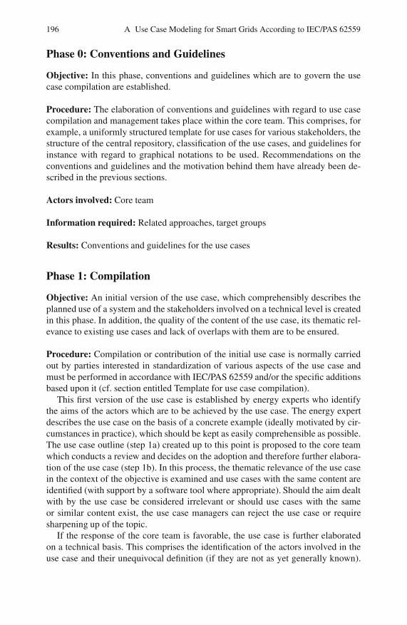
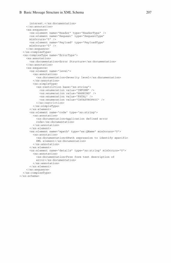
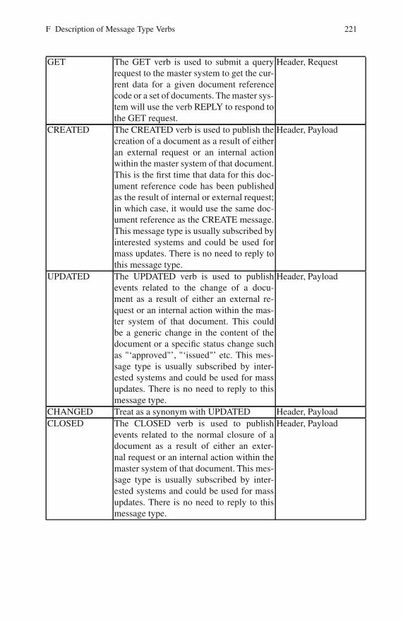

Index 241
Web Service 107WSDL 127
XMI 132XML 60 107 127
Attributes 61Document Structure 63
Elements 61Message 127
Namespace 64
Naming and Design 29XML Schema 127
XSD 134