Embed Size (px)
Citation preview

APPENDIX A

ARGONNE NATIO
DRAWN BY D. OLSON
\JAL LABORATORY-WEST
DATE DWG NO 5-21 -04 SITE-235
A N L - 3 5 OPERABLE UNIT 9-04 OF WAG-9
'I
i 757A \ a -
I- 57.7
'Ir--
0' 100' 200' 300'
/ SCALE I N FEET
TYPICAL CROSS SECTION OF DITCH
SAMPLE LOCATION & SILVER CONCENTRATION AREAS OF HIGHEST CON C E NTRAT IO N
SCALE: NONE THIS DRAWING IS THE PROPERTY OF
ARGONNE fiU\ NATIONAL LABORATORY
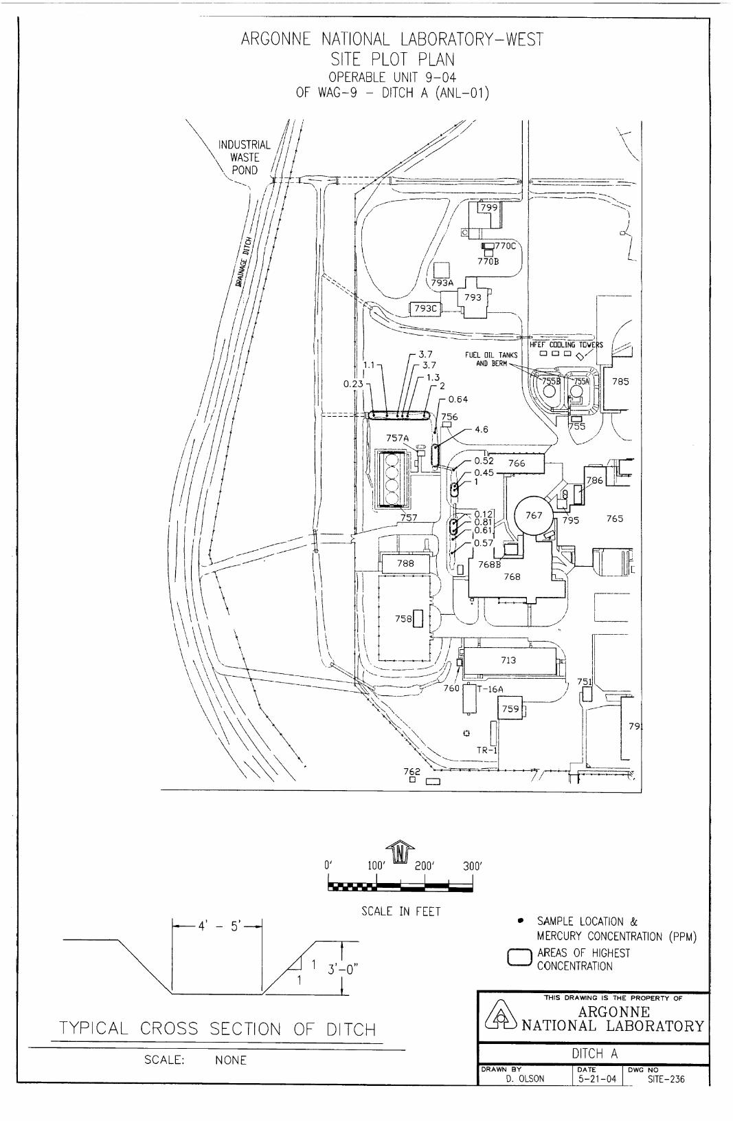
ARGON N E NATlO NAL LAB0 RAT0 RY - W EST SITE PLOT PLAN OPERABLE UNIT 9-04
OF WAG-9 - DITCH A (ANL-01)
'\ A i i; L- \ \ '\ \
0' 100' 300'
SCALE I N FEET -4' - 5'
I 1 /f 3'-0'' I
SAMPLE LOCATION & MERCURY CONCENTRATION (PPM) AREAS OF HIGHEST C 0 N C E NT RAT I 0 N
TYPICAL CROSS SECTION OF DITCH
SCALE: NONE
'THIS DRAWING IS THE PROPERTY OF
ARGONNE NATIONAL LABORATORY
DITCH A DRAWN BY DATE DWG NO
SITE- 236 D. OLSON 5-21 -04
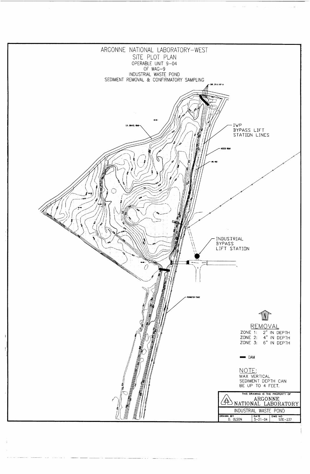
ARGONNE NATIONAL LABORATORY - WEST SITE PLOT PLAN OPERABLE UNIT 9-04
OF WAG-9 INDUSTRIAL WASTE POND
SEDIMENT REMOVAL & CONFIRMATORY SAMPLING

APPENDIX B
October 1999 "500-000-ES-04
;;tiZETT:J'lENT
WELFARE
DIVISION OF ENVIRONMENTAL QUALITY
Operable Unit 9-04 Idaho National Engineering and Enviror mental Laboratory
Idaho Falls, Idaho

This page intentionally left blank.
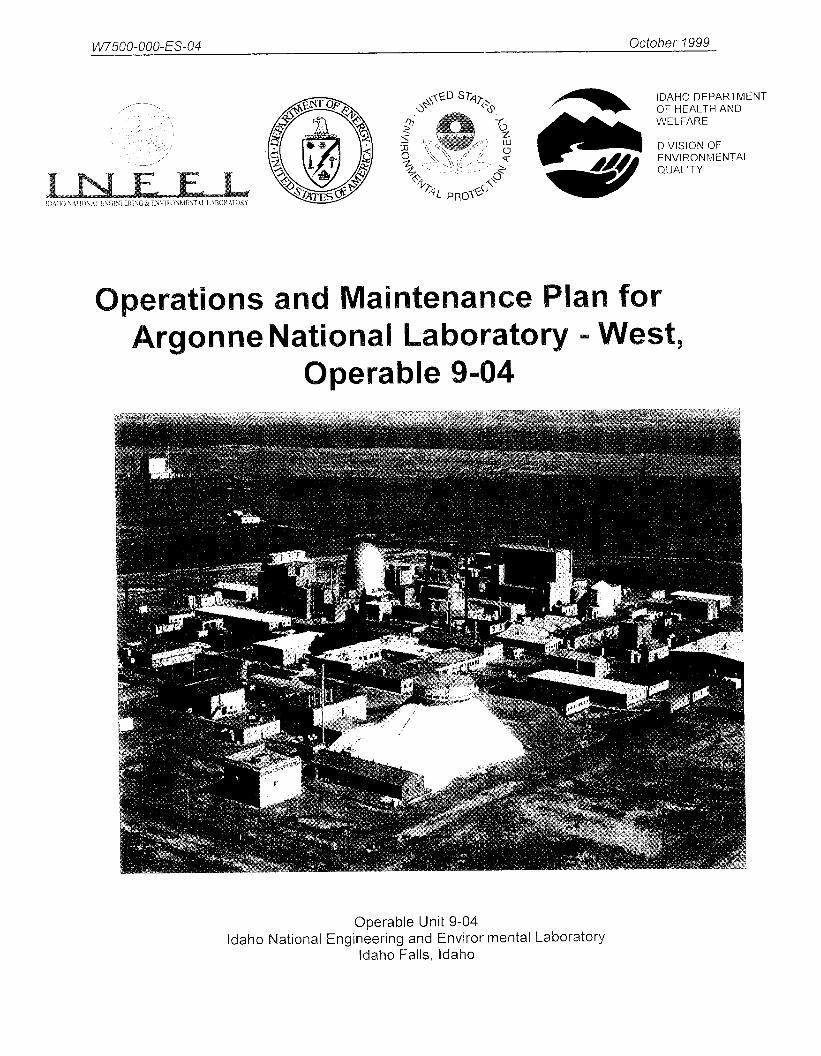
Operations and Maintenance Plan for Argonne National Laboratory - West,
Operable Unit 9-04,
Published October 1999 Document # WOOO1-1016-ES-00
Prepared by:
The Department of Energy The Idaho Department of Health and Welfare-Division of Environmental Quality
and the Environmental Protection Agency-Region 10
Operable Unit 9-04 Idaho National Engineering and Environmental Laboratory
Idaho Falls, Idaho
i

This page intentionally left blank.
.. 11

Abstract
The final Record of Decision (ROD) for Waste Area Group 9, Operable Unit (OU) 9-04, was signed in September 1998. This Record of Decision provides for long-term (100 years) operations and maintenance for three sites at Argonne National Laboratory-West (ANL-W). These three sites have remediation-goal cleanup levels established for current radionuclide activity levels that will decay to acceptable levels in 100 years. The three sites at ANL-W that require operations and maintenance are the Industrial Waste Pond, Interceptor Canal-Canal, and Interceptor Canal-Mound. All three sites have cesium- 137 as the radionuclide that poses an unacceptable risk under the current and future resident scenarios. When these three sites are remediated, the remaining cesium- 137 activity is equal to or less than the established remediation goal, and natural decay of the cesium- 137 has occurred for the next 100 years, the three sites would no longer require the institutional controls and continuation of this operations and maintenance plan.
... 111
This page intentionally left blank
iv

Table of Contents
ACRONYMS . . . . . . . . . . . . . . . . . . . . . . . . . . . . . . . . . . . . . . . . . . . . . . . . . . . . . . . . . . . . . . . . . . . . . . vii
1 GENERAL . . . . . . . . . . . . . . . . . . . . . . . . . . . . . . . . . . . . . . . . . . . . . . . . . . . . . . . . . . . . . . . . . 1-1
2 REVEGETATED AREAS AND EROSION CONTROL . . . . . . . . . . . . . . . . . . . . . . . . . . . . . 2-1
3 MONITORING . . . . . . . . . . . . . . . . . . . . . . . . . . . . . . . . . . . . . . . . . . . . . . . . . . . . . . . . . . . . . . 3-1
4 INSTITUTIONAL CONTROLS . . . . . . . . . . . . . . . . . . . . . . . . . . . . . . . . . . . . . . . . . . . . . . . . 4-1
5 ORGANIZATION AND RESPONSIBILITIES . . . . . . . . . . . . . . . . . . . . . . . . . . . . . . . . . . . . . 5-1 5.1 Organization . . . . . . . . . . . . . . . . . . . . . . . . . . . . . . . . . . . . . . . . . . . . . . . . . . . . . . . . . . . . 5-1
5.1.1 DOE Project Manager . . . . . . . . . . . . . . . . . . . . . . . . . . . . . . . . . . . . . . . . . . . . 5-1 5.1.2 ANL-W WAG 9, OU 9-04 Remediation Project Manager . . . . . . . . . . . . . . . 5-1
5.2 Conducting Inspections and Repairs . . . . . . . . . . . . . . . . . . . . . . . . . . . . . . . . . . . . . . . . . 5-1 5.2.1 Inspections . . . . . . . . . . . . . . . . . . . . . . . . . . . . . . . . . . . . . . . . . . . . . . . . . . . . 5-1 5.2.2 RepairReplacement of Material . . . . . . . . . . . . . . . . . . . . . . . . . . . . . . . . . . . . 5-2
6 REPORTING REQUIREMENTS . . . . . . . . . . . . . . . . . . . . . . . . . . . . . . . . . . . . . . . . . . . . . . . 6-1 6.1 Inspection . . . . . . . . . . . . . . . . . . . . . . . . . . . . . . . . . . . . . . . . . . . . . . . . . . . . . . . . . . . . . . 6-1 6.2 Maintenance . . . . . . . . . . . . . . . . . . . . . . . . . . . . . . . . . . . . . . . . . . . . . . . . . . . . . . . . . . . . 6-1 6.3 Reporting . . . . . . . . . . . . . . . . . . . . . . . . . . . . . . . . . . . . . . . . . . . . . . . . . . . . . . . . . . . . . . 6-1
APPENDIX A Administrative Record . . . . . . . . . . . . . . . . . . . . . . . . . . . . . . . . . . . . . . . . . . . . . . . . . B- 1
V

Figures
Figure 1- 1 . Location of the three WAG 9 OU 9-04 sites covered by this O& M plan . . . . . . . . . . . . . . 1-3
Tables
Table 1 . 1 . Long-term monitoring requirements for OU 9.04 . . . . . . . . . . . . . . . . . . . . . . . . . . . . . . . . . 1-2 Table 5- 1 . Summary of the OU 9-04 inspection schedules . . . . . . . . . . . . . . . . . . . . . . . . . . . . . . . . . . . 5-2
vi

ANL-W CERCLA DEQ DOE-CH EPA GPRS IDHW INEEL O&M ou ROD RGs WAG 9
Argonne National Laboratory - West Comprehensive Environmental Response, Compensation, and Liability Act Division of Environmental Quality Department of Energy-Chicago Operations Office Environmental Protection Agency - Region 10 global-positioning radiometric scanner Idaho Department of Health and Welfare Idaho National Engineering and Environmental Laboratory Operations and Maintenance Operable Unit Record of Decision remediation goals Waste Area Group 9
vii

This page intentionally left blank
... Vlll

Waste Area Group 9 Operations and Maintenance Plan
1 GENERAL
This site-specific operation and maintenance (O&M) plan describes the activities and procedures required for institutional controls at the Industrial Waste Pond, Interceptor Canal-Canal, and Interceptor Canal-Mound sites at ANL-W. The location of each site with respect to ANL-W is shown in Figure 1-1. In addition, five areas at ANL-W that pose unacceptable ecological risks will undergo remedial action and be remediated to concentrations that will be protective of human health and the environment. The remaining 33 sites at ANL-W do not pose unacceptable risks to human health and the environment and do not require any remedial action or any ongoing operations and maintenance procedures.
After remediation activities have been completed and the remediation goals met, ongoing operation and maintenance comprise the scope of anticipated activities. Basic elements of this O&M plan include (refer to Table 1-1):
0 Description of inspection procedures.
0 Procedures for repair and maintenance of signs and barriers (as part of the institutional controls).
0 Reporting policies and practices.
Photographs will be used to enhance the informative quality of documentation whenever possible, particularly when scheduled maintenance activities result in comments by the inspector. A record of these photographs, preserved in a site inspection photo log, will be maintained by the Waste Area Group (WAG) 9 remediation project manager and made available for review by the U.S. Department of Energy Chicago Operations Office (DOE-CH), U.S. Environmental Protection Agency (EPA) Region 10, and the Idaho Department of Health and Welfare (IDHW) Division of Environmental Quality (DEQ).
This O&M plan is intended only to serve as a procedure for monitoring ongoing operations at the site and to identify maintenance activities that will be conducted. It is not intended to serve as an Institutional Control Plan or as a five-year review document. However, these documents do have similarities and aspects of tasks performed as part of this O&M Plan may be utilized in the other documents.
1-1

Table 1-1. Long-Term Monitoring Requirements for OU 9-04.
Site Requirement Action
Industrial Waste Pond
Groundwater monitoring must continue for the next 20 years to ensure that concentrations do not increase and that modeling predictions remain valid.
Semi-annual groundwater samples will be collected for the next 20 years in accordance with the WAG 9 Groundwater Monitoring Plan.
Radiological surveys must be performed every 5 years to ensure that radionuclide concentrations are not increasing.
Surveys will be conducted by a Health Physics Technician in accordance with Table 5-1 of this O&M Plan and with Table 10-1 of the OU 9-04 Remedial Action Work Plan every 5 years.
Inspections will be conducted by an environmental engineer in accordance with Table 5-1 of this O&M Plan and with Table 10-1 of the OU 9-04 Remedial Action Work Plan.
The area must be posed with institutional controls (signs, markers, and land-use restrictions) for the next 100 years.
Interceptor Canal-Canal
Groundwater monitoring must continue for the next 20 years to ensure that concentrations do not increase and that modeling predictions remain valid.
Radiological surveys must be performed every 5 years to ensure that radionuclide concentrations are not increasing.
The area must be posed with institutional controls (signs, markers, and land-use restrictions) for the next 100 years.
Semi-annual groundwater samples will be collected for the next 20 years in accordance with the ANL-W Groundwater Monitoring Plan.
Surveys will be conducted by a Health Physics Technician in accordance with Table 5-1 of this O&M Plan and with Table 10-1 of the OU 9-04 Remedial Action Work Plan every 5 years.
Inspections will be conducted by an environmental engineer in accordance with Table 5- 1 of this O&M Plan and with Table 10- 1 of the OU 9-04 Remedial Action Work Plan.
Interceptor Canal-Mound
Groundwater monitoring will continue for the next 20 years to ensure that concentrations do not increase and that the modeling predictions remain valid.
Semi-annual groundwater samples will be collected for the next 20 years in accordance with the WAG 9 Groundwater Monitoring Plan.
Groundwater monitoring must continue for the next 20 years to ensure that concentrations do not increase and that modeling predictions remain valid.
Inspections will be conducted by an environmental engineer in accordance with Table 5- 1 of this O&M Plan and with Table 10- 1 of the OU 9-04 Remedial Action Work Plan.
Radiological surveys must be performed every 5 years to ensure that radionuclide concentrations are not increasing. O&M Plan
Revegetation and erosion surveys will be conducted in accordance with Table 5-1 of this
The area must be posed with institutional controls (signs, markers, and land-use restrictions) for the next 100 years.
Surveys will be conducted by a health physics technician in accordance with Table 5-1 of this O&M Plan and with Table 10- 1 of the OU 9-04 Remedial Action Work Plan every 5 years.
1-2

// / Y w
WASTE POND
INTERCEPTOR CANAL- MOUN
INTERCEPTOR
Figure 1-1. Location of the three WAG 9 OU 9-04 sites covered by this O& M plan.
1-3
f
This page intentionally left blank.
1-4
2
Reseeding will be performed only at the ANL-W Interceptor Canal-Mound site. This site is located west of ANL-W outside the security fences. The irrigation system at the Interceptor Canal-Mound will remain inplace and active while the revegetation activities are being completed. DOE anticipates that it would only take one to two years of supplemental watering to establish a successful revegetation of the Interceptor Canal-Mound. The other WAG 9 sites being remediated are active drainage ditches or surface water infiltratiodevaporation ponds and will not be revegetated. The drainage ditches will continue to drain surface water runoff from rainfall or rapid melting of snow. All of the surface water runoff at ANL- W flows to the west and then is routed to the north to the Industrial Waste Pond. The Industrial Waste Pond will remain in service as a water infiltration and evaporation pond.
The Interceptor Canal-Mound reseeded area will be monitored qualitatively during annual inspections, in late summer for 3 years following reseeding to ensure proper growth. Qualitative determinations of nongrowth or sparse growth areas will be made through comparative growth evaluations in undisturbed areas near the disturbed areas with consideration of the length of time since planting. Information will be recorded on the inspection reporting forms shown in Appendix A of this document. If seeding failure is experienced, as evidenced by lack of perennial grass establishment, and invasion by weeds (primarily Russian thistle, cheatgrass, and tumble mustard) will be documented and photographed. Reseeding and fertilization procedures will be evaluated to determine what went wrong with the original seeding and updated as necessary. Reseeded areas will require follow-up inspections in late summer for 3 years to verify successful reseeding.
Surface erosion is not anticipated to be a problem at the Interceptor Canal-Mound site since it will have been leveled to grade with an approximately 2% slope toward the west. Observations of soil movement, as evidenced by the accumulation of soil on the up-slope side of plants, pedestaling of plants or rocks, or formation of rills or gullies, will be recorded (on the inspection reporting forms in Appendix A) with the extent of erosion noted. If rills and gullies are detected, appropriate soil will be added and compacted to bring the affected area up to the surrounding grade, as determined by visual approximation, and then reseeded. Photographs will be taken as needed.
2- 1
This page intentionally left blank.
2-2
3 Surface radiological monitoring will be performed every five years to identify potential migration
from the Industrial Waste Pond, Interceptor Canal-Canal, and the Interceptor Canal-Mound to ensure that existing institutional controls are protective of residential exposure for A m - W . Radiological-surface surveys will be performed using a global-positioning radiometric scanner (GPRS) mounted on the front of a four-wheel drive vehicle. The GPRS system will be used to locate and document areas of high gamma activity. For areas identified by the GPRS that are above previous surveys, a portable high-purity germanium gamma spectroscopy detector will be used to determine if the radiological contamination is above the remediation goals (RGs), as identified in OU 9-04 ROD. If radionuclide contamination is above the RGs, DOE-CH, U.S. Environmental Protection Agency Region 10, and Idaho Department of Health and Welfare Division of Environmental Quality will be notified and corrective actions will be determined by these agencies.
3-1

This page intentionally left blank.
3 -2
4 INSTITUTIONAL CONTROLS
The purpose of institutional controls is to restrict human access to the Industrial Waste Pond, Interceptor Canal-Canal, and Interceptor Canal-Mound. By restricting access to these sites the exposure pathway for cesium- 137 to human residents in aresidential-exposure scenario can be controlled. Thus, by preventing exposure, risks are acceptable. Institutional controls will be evaluated and inspected during the 5-year reviews. Institutional controls include:
a Site signs
a Permanent markers
a Postings
a Land use restrictions.
The controls will be inspected and their status registered on the inspection reporting form (shown in Appendix A). Institutional controls found to be damaged or missing will be repaired or replaced.
4- I

This page intentionally left blank.
4-2

5
This section outlines the organizational practices that will drive O&M activities and specifies individuals responsible for inspections, repairs, and reporting required by WAG 9, OU 9-04.
5.1 Organization
5.1.1 DOE Project Manager
The DOE-CH WAG 9 Remediation Project manager is responsible for the following:
0 Ensuring the O&M activities are performed in accordance with the approved plan
0 Coordinating activities of the INEEL operating contractor at WAG 9, OU 9-04.
5.1.2 ANL-W WAG 9, OU 9-04 Remediation Project Manager
As the point of contact for O&M activities, the ANL-W WAG 9 Remediation Project Manager is responsible for the following:
0 Ensuring copies of inspection reports, are placed in the project records file
0 Administrating subcontracts for performing required repairs
0 Reporting activities to DOE-ID.
5.2 Conducting Inspections and Repairs
5.2.1 Inspections
The WAG 9 ANL-W Remediation Project Manager will provide qualified personnel to inspect signs, permanent markers, postings, and land use restrictions per institutional controls for the Industrial Waste Pond, Interceptor Canal-Canal, and Interceptor Canal-Mound in accordance with the approved O&M plan. These inspections will be documented in accordance with Section 6 of this document. Table 5- 1 summarizes the inspection schedules for the Industrial Waste Pond, Interceptor Canal-Canal, and the Interceptor Canal-Mound sites. Personnel will be trained on requirements of the approved plan prior to performing these inspections. The ANL-W WAG 9 Remediation Project Manager is responsible for implementation and reporting of inspections.
After 5 years, the frequency of inspection and reporting will be reevaluated by WAG 9 DOE-CH, U.S. Environmental Protection Agency Region 10, and Idaho Department of Health and Welfare Division of Environmental Quality Remediation Project Managers.
5- 1

Table 5- 1. Summary of the OU 9-04 Inspection Schedules.
Inspections Frequency
Revegetation with native plants"
Erosion survey Every 5 years
Radiological surveys Every 5 years
Signs and postings Every 5 years
Permanent markers Every 5 years
Land use restrictions Every 5 years
In late summer for 3 years following seeding
a Interceptor Canal-Mound only.
5.2.2 Repair/Replacement of Material
The ANL-W WAG 9 Remediation Project Manager will obtain the services of qualified personnel, as necessary, to repair or replace any warning signs and postings around the WAG 9,0U-9-04 sites (identified by inspections) that require corrective action in accordance with the approved O&M plan. The Remediation Project Manager will provide construction management support for maintenance activities and document all repairs or replacements in accordance with current procedures.
5 -2
6 REPORTING REQUIRFMENTS
6.1 Inspection
Inspections of the WAG 9, OU 9-04 sites will fall into three types:
Scheduled inspections
Follow-up inspections for reseeding
Contingency Inspections.
ScA,eduled inspections are summarized in Table .1. Follow-up inspections for repairheplacement activities will occur as determined by the ANL-W Remediation Project Manager. Contingency inspections are unscheduled inspections ordered by DOE-CH; trigger events for these inspections may include severe rainstorms, floods, or highly unusual events such as tornadoes or earthquakes.
The ANL-W WAG 9 Remediation Project Manager will record inspection results on the attached inspection reporting forms (Appendix A). The forms will be completed, signed, dated, and submitted to DOE-CH annually, or as needed in the case of contingency inspections.
6.2 Maintenance
No routine maintenance is planned for the sites. Unscheduled custodial maintenance activities will be determined during inspections. The ANL-W WAG 9 Remediation Project Manager will develop the work plan citing required maintenance activities as identified by inspection reports to be submitted to the DOC-CH for required maintenance activities. The work plan will include a technical work scope, cost estimate, schedule, a reference list of existing applicable technical specifications and drawings, and health and safety requirements.
6.3 Reporting
The five year O&M report will irclude documentation of scheduled inspections, follow-up and contingency inspections, and maintenance activities. This O&M report will attached to the CERCLA 5 year review checklist and include:
0 A summary of the inspection
0 A summary of maintenance activities to date
0 An estimate of maintenance activities required in the upcoming years
0 An assessment of inspection data, and applicable photos
0 A list of field inspector names and qualifications
0 A copy of the appropriate inspection report forms.
6- 1
This page intentionally left blank.
6-2

Appendix A
Inspection Report Forms for ANL-W OU 9-04 Operations and Maintenance Plan

This page intentionally left blank.

5 Year Inspection Form
Task
Has an on site inspection been completed?
for the ANL-W Industrial Waste Pond as Required by the
Yes No
OU 9-04 Operations and Maintenance Plan
Are human residents living within 50 meters of the Industrial Waste Pond site?
I Are the warning signs in place and still readable at the Industrial Waste Pond site?
I I Are the land use restrictions for the Industrial Waste Pond recorded and available for inspection at the Bingham county courthouse?
Are radiological survey results increasing?
Were any air, soil, or groundwater samples collected? If yes attach summary of results.
Are there any construction or mining activities that threaten to encroach on or undermine this site?
Are the Institutional Controls (warning signs and land use restrictions) at the Industrial Waste Pond site still protective?
Are current photos of this site attached to this checklist?
Is the current responsible federal agency contact person and address identified and attached to this check list?
Is a review needed prior to the next five year review?
Scheduled date for submittal of next five-year review
Signature of Engineer Responsible for completing this review Date
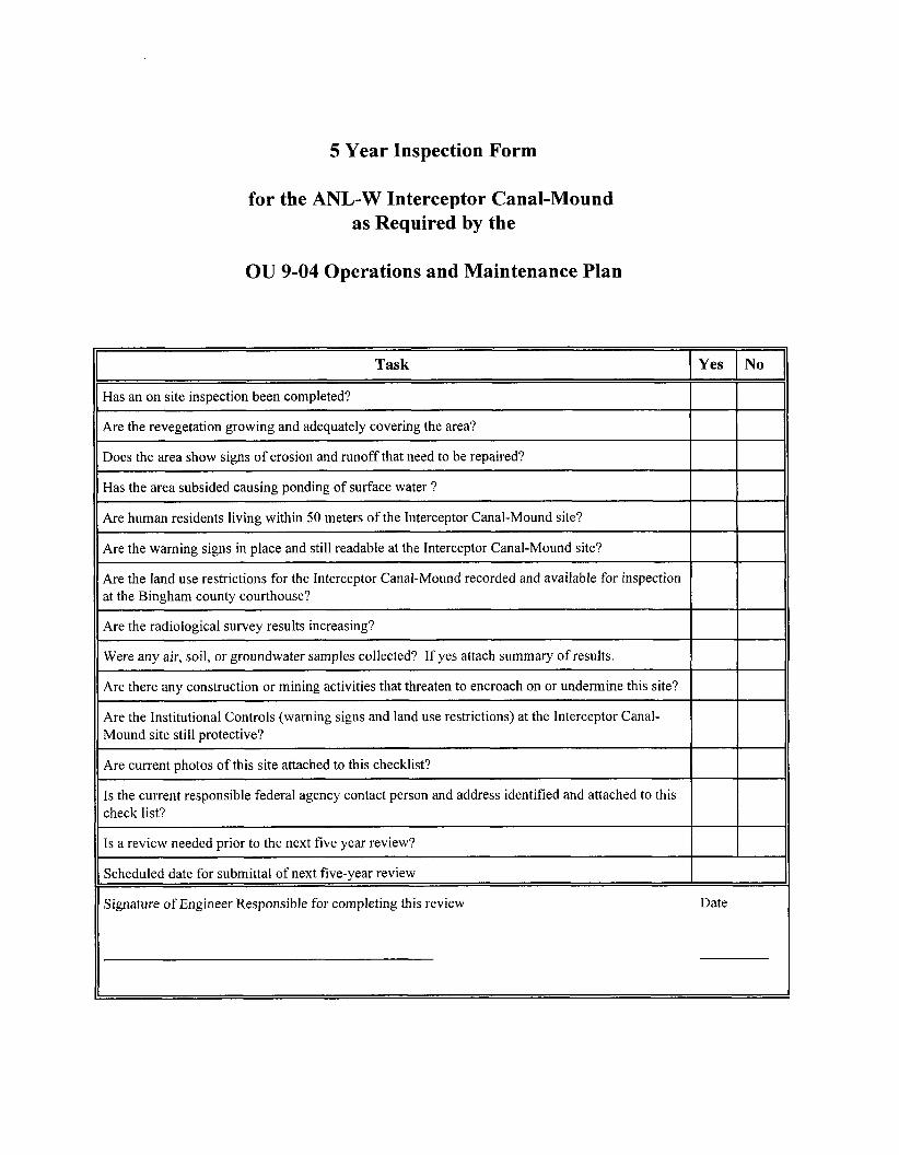
5 Year Inspection Form
Has an on site inspection been completed?
Are the revegetation growing and adequately covering the area?
Does the area show signs of erosion and runoff that need to be repaired?
I
I Has the area subsided causing ponding of surface water ?
Are human residents living within 50 meters of the Interceptor Canal-Mound site?
for the ANL-W Interceptor Canal-Mound as Required by the
~~
~ Are the warning signs in place and still readable at the Interceptor Canal-Mound site?
OU 9-04 Operations and Maintenance Plan
Task I Yes I NO
for the Interceptor Canal-Mound recorded and available for inspection at the Bingham county courthouse?
Ibeihe radiological survey results increasing?
Were any air, soil, or groundwater samples collected? If yes attach summary of results.
Are there any construction or mining activities that threaten to encroach on or undermine this site?
Are the Institutional Controls (warning signs and land use restrictions) at the Interceptor Canal- Mound site still protective?
Are current photos of this site attached to this checklist?
Is the current responsible federal agency contact person and address identified and attached to this check list?
Is a review needed prior to the next five year review?
Scheduled date for submittal of next five-year review
Signature of Engineer Responsible for completing this review Date
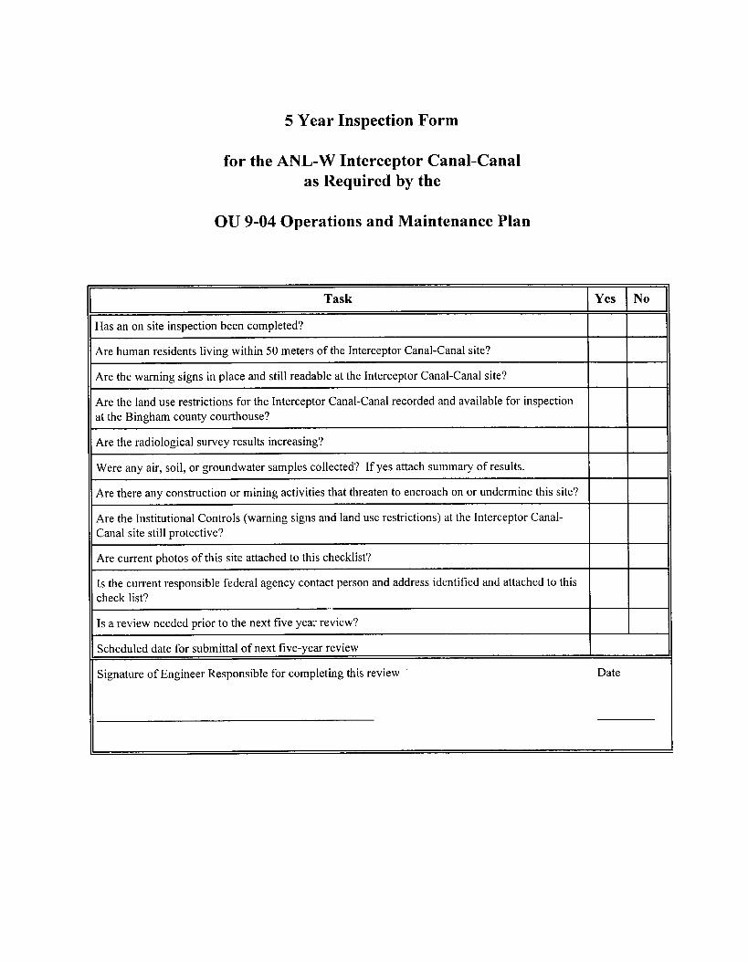
5 Year Inspection Form
for the ANL-W Interceptor Canal-Canal as Required by the
OU 9-04 Operations and Maintenance Plan
Task
Has an on site inspection been completed?
Are human residents living within 50 meters of the Interceptor Canal-Canal site?
Yes I No
I Are the warning signs in place and still readable at the Interceptor Canal-Canal site?
~~~
Are the land use restrictions for the Interceptor Canal-Canal recorded and available for inspection at the Bingham county courthouse?
Are the radiological survey results increasing?
Were any air, soil, or groundwater samples collected? If yes attach summary of results. ~~~
I G y construction or mining activities that threaten to encroach on or undermine this site? I I Are the Institutional Controls (warning signs and land use restrictions) at the Interceptor Canal- II Canal site still protective?
~~~
Are current photos of this site attached to this checklist?
Is the current responsible federal agency contact person and address identified and attached to this check list?
Is a review needed prior to the next five yea: review?
Scheduled date for submittal of next five-year review
Signature of Engineer Responsible for completing this review
I
Date
APPENDIX C

Appendix C
WAG 9 Quality Assurance Project Plan
For Argonne National Laboratory-West for Remedial Action in OU 9-04
at the Idaho Nationai Engineering and Environmental Laboratory
Prepared By Argonne National Laboratory-West
This page intentiody left blank.

WAG 9 Quality Assurance Project Plan
For Argonne National Laboratory-West Remedial Action in OU 9-04
at the Idaho National Engineering and Environmental Laboratory
Published May 2004
Revision 1 WOO0 1-1 0 15-ES-01
Prepared By:
Approved By: 6-3-09 Environmedal Programs, Manager Date
Prepared By Argonne National Laboratory-West
P.O. Box 2528 Idaho Falls, Idaho 83403-2528
Prepared for the U.S. Department of Energy
and University of Chicago for Management and Operations of Argonne National Laboratory
Under DOE Chicago Operations Office Contract W-3 1 - 109-ENG-3 8 Mod # 23 9

This page intentionally left blank

Environmental Projects May 2004 ~ u a l i t y AssuranceProject plan WOOO1- 10 1 5-ES-0 1 for OU 9-04 Remedial Action Page iii of viii
Table of Contents
ACRONYMS . . . . . . . . . . . . . . . . . . . . . . . . . . . . . . . . . . . . . . . . . . . . . . . . . . . . . . . . . . . . . vii
1 . PURPOSE . . . . . . . . . . . . . . . . . . . . . . . . . . . . . . . . . . . . . . . . . . . . . . . . . . . . . . . . . . 1
2 . PRO..DEScRIpTION . . . . . . . . . . . . . . . . . . . . . . . . . . . . . . . . . . . . . . . . . . . . . 1
. . . . . . . . . . . . . . . . . . . 3 . PROJECT ORGANIZATION AND RESPONSIBILITIES 1
4 . QUALITY ASSURANCE OBJECTIVES FOR MEASUREMENTS . . . . . . . . . . . . 4 Quantitative Quality Assurance Objectives . . . . . . . . . . . . . . . . . . . . . . . . . . 4 4.1.1 Precision . . . . . . . . . . . . . . . . . . . . . . . . . . . . . . . . . . . . . . . . . . . . . . 5
4.1.1.2 Laboratory Precision . . . . . . . . . . . . . . . . . . . . . . . . . . . 5
4.1.2.2 Laboratory Accuraey . . . . . . . . . . . . . . . . . . . . . . . . . . . 6 4.1.3 Detection Limit . . . . . . . . . . . . . . . . . . . . . . . . . . . . . . . . . . . . . . . . . 6 4.1.4 Completeness . . . . . . . . . . . . . . . . . . . . . . . . . . . . . . . . . . . . . . . . . . 7 Qualitative QA Objectives . . . . . . . . . . . . . . . . . . . . . . . . . . . . . . . . . . . . . . . . 7 4.2.1 Comparability . . . . . . . . . . . . . . . . . . . . . . . . . . . . . . . . . . . . . . . . . . 7 4.2.2 Representativeness . . . . . . . . . . . . . . . . . . . . . . . . . . . . . . . . . . . . . . 7 4.2.3 Analytical Levels . . . . . . . . . . . . . . . . . . . . . . . . . . . . . . . . . . . . . . . . 7
4.1
4.1.1.1 Field Precision . . . . . . . . . . . . . . . . . . . . . . . . . . . . . . . . 5
4.1.2 Accuracy . . . . . . . . . . . . . . . . . . . . . . . . . . . . . . . . . . . . . . . . . . . . . . 5 4.1.2.1 Field Accuracy . . . . . . . . . . . . . . . . . . . . . . . . . . . . . . . . 5
4.2
5 . SAMPLING . . . . . . . . . . . . . . . . . . . . . . . . . . . . . . . . . . . . . . . . . . . . . . . . . . . . . . . . . 8 5.1
5.3 Sample Labels 9 5.4
5.6 ....................................................... 10 5.7 5.8 5.9
Sampling Location Selection . . . . . . . . . . . . . . . . . . . . . . . . . . . . . . . . . . . . . . 8 5.2 Presampling Considerations . . . . . . . . . . . . . . . . . . . . . . . . . . . . . . . . . . . . . . 9
Sample Identification Numbers . . . . . . . . . . . . . . . . . . . . . . . . . . . . . . . . . . . . 9 5.5 Custody Seals . . . . . . . . . . . . . . . . . . . . . . . . . . . . . . . . . . . . . . . . . . . . . . . . . . 9
Chain of Custody . . . . . . . . . . . . . . . . . . . . . . . . . . . . . . . . . . . . . . . . . . . . . . 10 Sampling and Equipment Procedures . . . . . . . . . . . . . . . . . . . . . . . . . . . . . . 11 Sample Equipment Decontamination . . . . . . . . . . . . . . . . . . . . . . . . . . . . . . 11
5.10 Sample Preservation and Holding Times . . . . . . . . . . . . . . . . . . . . . . . . . . . 11
. . . . . . . . . . . . . . . . . . . . . . . . . . . . . . . . . . . . . . . . . . . . . . . . . .
6 . ANALYTICALPROCEDURES . . . . . . . . . . . . . . . . . . . . . . . . . . . . . . . . . . . . . . . . 11
7 . CALIBRATION PROCEDURES . . . . . . . . . . . . . . . . . . . . . . . . . . . . . . . . . . . . . . . 11

Environmental Projects May 2004 Quality Assurance Project Plan WOO0 1 . 101 5-ES-0 1 for OU 9-04 Remedial Action Pageivofviii
8. DATA ~ U ~ O N . VALIDATION. AND REPORTING . . . . . . . . . . . . . . . . . . 12 8.1 Data Reduction . . . . . . . . . . . . . . . . . . . . . . . . . . . . . . . . . . . . . . . . . . . . . . . . 12 8.2 Data Validation . . . . . . . . . . . . . . . . . . . . . . . . . . . . . . . . . . . . . . . . . . . . . . . 12 8.3 DataReporting . . . . . . . . . . . . . . . . . . . . . . . . . . . . . . . . . . . . . . . . . . . . . . . . 12
9 . INTERNAL QUALITY CONTROL CHECKS . . . . . . . . . . . . . . . . . . . . . . . . . . . . 13 Laboratory Quality Control . . . . . . . . . . . . . . . . . . . . . . . . . . . . . . . . . . . . . . 13 Field Q u d i Control . . . . . . . . . . . . . . . . . . . . . . . . . . . . . . . . . . . . . . . . . . . 13
9.1 9.2
10 . PERFORMANCE AND SYSTEMS ASSESSMENTS . . . . . . . . . . . . . . . . . . . . . . . 14 10.1 Performance Assessments . . . . . . . . . . . . . . . . . . . . . . . . . . . . . . . . . . . . . . . 14 10.2 Systems Assessments . . . . . . . . . . . . . . . . . . . . . . . . . . . . . . . . . . . . . . . . . . . 15
11 . CALCULATION OF DATA QUALITY INDICATORS . . . . . . . . . . . . . . . . . . . . . 15 11.1 Precision . . . . . . . . . . . . . . . . . . . . . . . . . . . . . . . . . . . . . . . . . . . . . . . . . . . . . 15 11.2 Accuracy . . . . . . . . . . . . . . . . . . . . . . . . . . . . . . . . . . . . . . . . . . . . . . . . . . . . . 17 11.3 Completeness . . . . . . . . . . . . . . . . . . . . . . . . . . . . . . . . . . . . . . . . . . . . . . . . . 18
12 . CORRECTIVEACTION . . . . . . . . . . . . . . . . . . . . . . . . . . . . . . . . . . . . . . . . . . . . . 18 12.1 Field Corrective Action(s) . . . . . . . . . . . . . . . . . . . . . . . . . . . . . . . . . . . . . . . 18
Laboratory Corrective Action(s) . . . . . . . . . . . . . . . . . . . . . . . . . . . . . . . . . . 18 12.2
13 . RECORDKEEPING . . . . . . . . . . . . . . . . . . . . . . . . . . . . . . . . . . . . . . . . . . . . . . . . . 19
14 . QUALITY ASSURANCE REPORTS . . . . . . . . . . . . . . . . . . . . . . . . . . . . . . . . . . . . 19
15 . PREVENTATJVE MAINTENANCE . . . . . . . . . . . . . . . . . . . . . . . . . . . . . . . . . . . . 19
16 . REFERENCES . . . . . . . . . . . . . . . . . . . . . . . . . . . . . . . . . . . . . . . . . . . . . . . . . . . . . 19
ATTACHMENTS . . . . . . . . . . . . . . . . . . . . . . . . . . . . . . . . . . . . . . . . . . . . . . . . . . . . . . . . . 23
ATTACHlMENTAQAPjPTABLES . . . . . . . . . . . . . . . . . . . . . . . . . . . . . . . . . . . . . . . . . A-1
Environmental Projects May 2004
for OU 9-04 Remedial Action Page v of viii Quality Assurance Project Plan WOO01 -10 15-ES-0 1
List of Figures
Figure 1. Location of ANL-W with Respect to the INEEL and the State of Idaho . . . . . . . 2 Figure 2. Project Orgmnizational Structure for Remediation Activities at ANL-W . . . . . . 3

Environmental Projects May 2004
for OU 9-04 Remedial Action Page vi of viii Quality Assurance Project Plan WOO01 -1 0 15-ES-0 1
List of Tables
Table 1 . Table 2 . Table 2 . Table 3 . Table 4 . Table 5 . Table 6 . Table 6 . Table 7 . Table 8 . Table 9 . Table 10 . Table 11 . Miscellaneous Analytes . . . . . . . . . . . . . . . . . . . . . . . . . . . . . . . . . . . A-13 Table 12 . Table 13 . Table 14 . Table 15 .
3-90 SOW CLP Volatile Organic Target Compound List . . . . . . . . . . . . . . . A-1 3-90 SOW CLP Semivolatile Organ Target Compound List
3-90 SOW CLP Pesticide Organic Target Compound List . . . . . . . . . . . . . . A-4
ER Radionuclide Target Isotope List . . . . . . . . . . . . . . . . . . . . . . . . . . . . . . . A-6
. . . . . . . . . . . . A-2 3-90 SOW CLP Semivolatile Organ Target Compound List (cont) . . . . . . . A-3
3-90 SOW CLP Inorganic Target Analyte List . . . . . . . . . . . . . . . . . . . . . . . A-5
EPA Method 524.2 Target Analyte List . . . . . . . . . . . . . . . . . . . . . . . . . . . . . A-7 EPA Method 524.2 Target Analyte List (continued) . . . . . . . . . . . . . . . . . . . A-8 TCLP Volatile Organic Target Compound List . . . . . . . . . . . . . . . . . . . . . . A-9 TCLP Semivolatile Organic Target Compound List . . . . . . . . . . . . . . . . . . A-10 TCLP Met& Target Andyte List . . . . . . . . . . . . . . . . . . . . . . . . . . . . . . . . A-11 TCLP PesticidedEerbicides Target Compound List . . . . . . . . . . . . . . . . . . A-12
Field QC Samples . . . . . . . . . . . . . . . . . . . . . . . . . . . . . . . . . . . . . . . . . . . . . A-14 Summary of Sam , ESMi T i and Prcscrvrtislr
Requirements . . . . . . . . . . . . . . . . . . . . . . . . . . . . . . . . . . . . . . . . . . . . . . . . . . . . . A-15 SEIHI- af!%m@ngCdI&aon , Hddbg The, and Preservation
Requirements for Radkhgical Water Analyses . . . . . . . . . . . . . . . . . . . . . . . . . . A- 16 Physical Property Measurement Methods . . . . . . . . . . . . . . . . . . . . . . . . . . A- 17
Environmental Projects May 2004 Quality Assurance Project Plan WOO0 1-101 5-ES-0 1 for OU 9-04 Rernedial Action Page vii of viii
ACRONYMS
ANL-W AS0 Argonne Site ofliice ANSI American National Standards Institute ASTM American Standard Testing Methods CLP Contract Laboratory Program COC Chain of Custody CRDL Contract Required Detection Limits CRQL Contract Required Quanthtion K i t s DOE Department of Energy DOE-CH DOE-ID DQO Data Quality Objective EPA Environmental Protection Agency ER Environmental Restoration ESWMEnvironment, Safety and Waste Management FSP Field Sampling Plan INEELIdaho National Engineering and Environmental Laboratory DEQ MDL Method Detection Limit MS Matrix Spike OSHA ou Operable Unit PQL Practical Quantitation Limits QMQc Quality Assurance/Quality Control QAPjP Quality Assurance Project Plan RVFS Remedial InvestigatiodFeasibility Study RPD Relative Percent Merence RQL Required Quantitation Limit RRDL Required Radiological Detection Limit RSD Relative Standard Deviation RWP Radiation Work Permit SOP Standard Operation Procedures sow Statement of Work SRPA Snake River Plain Asuifer SWP Safe Work Permit TCLP Toxicity Characteristic Leaching Procedure WAG Waste Area Group
Argonne National Laboratory - West
Department of Energy, Chicago Operations Office Department of Energy, Idaho Operations OfKce
Idaho Department of Environmental Quality
Occupational Safety and Health Administration
Environmental Projects May 2004
for OU 9-04 Remedial Action Page viii of viii Quality Assurance Project Plan WOO0 1 - 10 15-ES-0 1
This page intentionally left blank.
Environmental Projects May 2004
for OU 9-04 Remexiid Adon Page 1 of 22 Quality Assurance Project Plan WOOO1-1015-ES-01
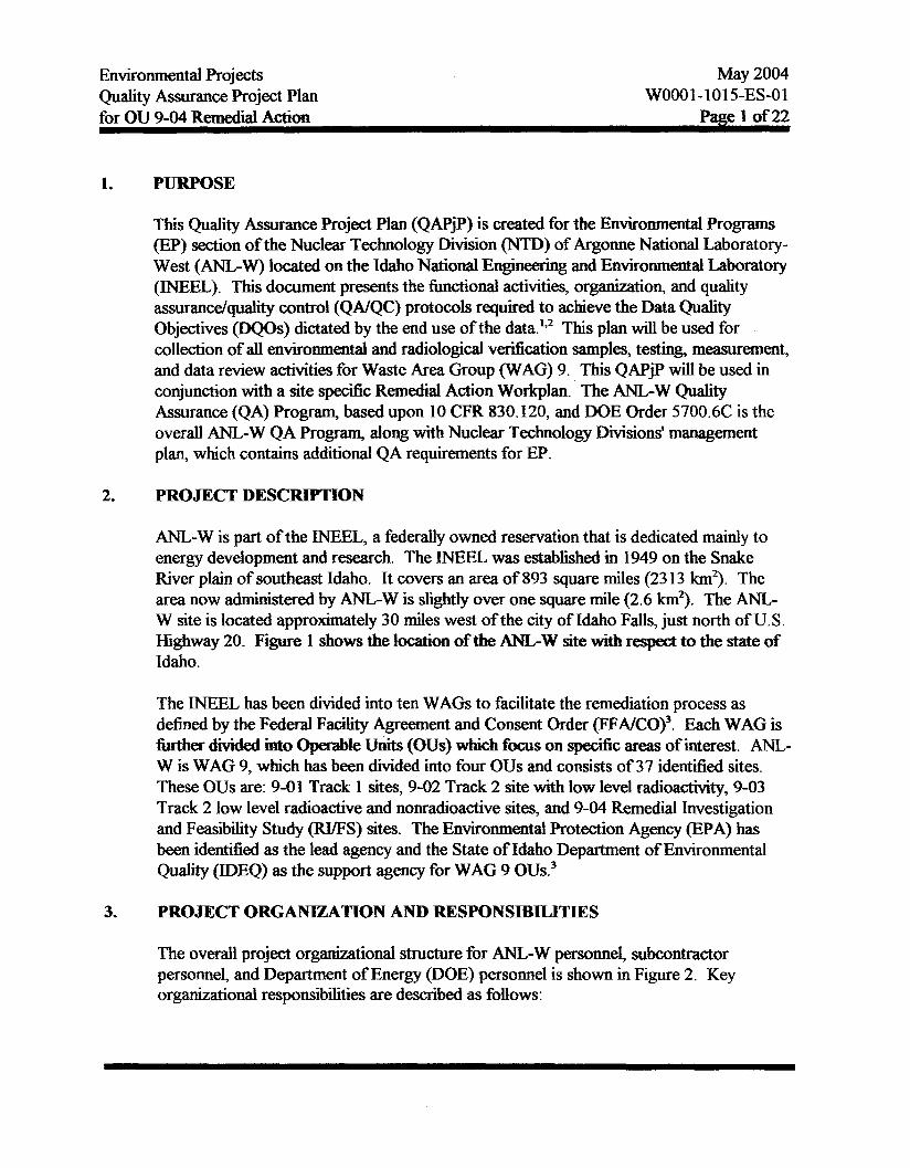
1. PURPOSE
This Quality Assurance Project Plan (QAPjj) is created for the Environmental Programs (EP) Section of the Nuclear Technology Division ("TI)) of Argonne National Laboratory- West (ANL-W) located on the Idaho National E n g k a h g and Environmental Laboratory (INEEL). This document presents the bctional activities, organization, and quality assurandquality control (QNQC) protocols required to achieve the Data Quality Objectives @QOs) dictated by the end use of the data.',2 This plan will be used for collection of all environmental and radiological verification samples, testing, measurement, and data review activities for Waste Area Group (WAG) 9. This QAPjP will be used in conjunction with a site spec& Remedial Action Workplan. The ANGW Quality Assurance (QA) Program, based upon 10 CFR 830.120, and DOE Order 5700.6C is the overall ANL-W QA Program, along with Nuclear Technology Divisions' management plan, which contains additional QA requirements for EP.
2. PROJECT DESCRIPTION
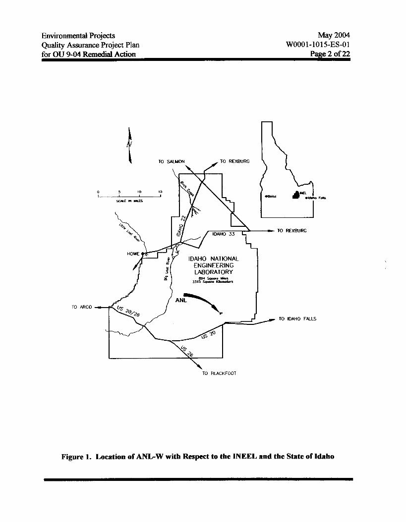
ANL-W is part of the INEFZL, a federally owned reservation that is dedicated mainly to energy development and research. The INEEL was established in 1949 on the Snake River plain of southeast Idaho. It covers an area of 893 square miles (23 13 km2). The area now administered by ANL-W is slightly over one square mile (2.6 km?. The ANL- W site is located approximately 30 miles west of the city of Idaho Falls, just north of U. S. Highway 20. Figure 1 shows the location of the ANL-W site with respect to the state of Idaho.
The INEEL has been divided into ten WAGS to facilitate the remediation process as defined by the Federal Facility Agreement and Consent Order (FFAKO)'. Each WAG is further divided into OperaMe Units (OUs) which focus on specific areas of interest. ANL- W is WAG 9, which has been divided into four OUs and consists of 37 identified sites. These OUs are: 9-01 Track 1 sites, 9-02 Track 2 site with low level radioactivity, 9-03 Track 2 low level radioactive and nonradioactive sites, and 9-04 Remedial Investigation and Feasibfity Study (RVFS) sites. The Environmental Protection Agency @PA) has been identified as the lead agency and the State of Idaho Department of Environmental Quality (IDEQ) as the support agency for WAG 9 OUS.~
3. PROJECT ORGANIZATION AND RESPONSIBILITIES
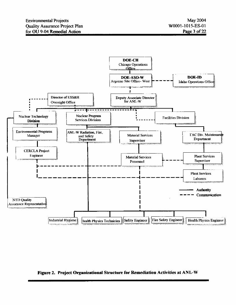
The overall project organizational structure for ANL-W personnel, subcontractor personnel, and Department of Energy (DOE) personnel is shown in Figure 2, Key organizational responsibilities are described as follows:
Environmental Projects May 2004
Page 2 of22 Quality Assurance Project Plan for OU 9-04 Remedial Adion
WOO0 1-1 01 5-ES-0 1
TO ARC0
Figure 1. Location of ANLW with Respect to the INEEL and the State of Idaho
Environmental Projects Quality Assurance Project Plan
May 2004 WOOO1-1015-ES-01
for OU 9-04 Remedial ActiOn Page 3 of 22
---- I
Director of ESsdzH I------
Facilities Division
Environmental Programs
Material Services Personnel
Figure 2. Project Organizational Structure for Remediation Activities at ANL-W

Environmental Projects May 2004
for OU 9-04 Remedial Action Page 4 of 22 Quality Assurance Project Plan W0001-1015-ES-01
0
0
0
4.
ANL-W CERCLA Project Engineer: The CERCLA Project Engineer is responsible for overall technical direction of the remedial action, providing direction to field team members, provision or coordination of all required personnel and subcontractor training, and for ensuring that ANL-W and subcontractor personnel and equipment resources are made available to support the needs of all field and laboratory operations conducted pursuant to the requirements of the Remedial Action Work Plan.
NTD Quality Assurance Representative: The NTD Quality Assurance Representative assigned to the investigation shall be responsible for monitoring and verifjing technical pdormance in compliance with the requirements of the Remedial Action Work Plan and its implementing procedures. The Quality Assurance Representative is responsible for coordinating any required external program assessment support services and is also responsible for initiating andor coordinating corrective action as necessary to ensure that the technical and quality goals of the investigation are achieved. The systems and program assessment methods are described in Section 10 of this QAPjP.
ANL-W Site Safety Engineer: The ANL-W Site Safety Engineer is responsible for conducting d e t y briefings at the start of each shift, and for initiating any required measures necessary to protect the health and safety of the site personnel.
QUALITY ASSURANCE OBJECTIVES FOR MEASUREMENTS
The overall project objective of a field investigation is to produce data of known type and quality that can be used to show that the remediation goals are met. Typically precision, accuracy, detection limit, completeness, comparability, representativeness, and analytical levels are used to determine the quality of the data.
The QA objectives are divided into those objectives which are quantitative and qualitative. The governing QA document for ANL-W is WOOO1-0929-QM. The quantitative QA objectives are those for which calculations of the numeric output can be used to determine if QA requirements are met. The qualitative QA objectives are those which do not require calculations of actual analytical data. QA objectives are needed for all critical measurements and for each type of sample matrix.5 A discussion of whether the DQOs of the project have been met, and the impacts on the decision process will be included in the data validation report.
4.1 Quantitative Quality Assurance Objectives
The quantitative QA parameters are precision, accuracy, detection limit, and completeness. The accuracy, precision, and method detection limit goals are contained in Tables 1 through 11 located in Attachment A.
Environmental Projects May 2004 Quality Assurance Project Plan WOO0 1- 101 5-ES-0 1 for OU 9-04 Remedial Action Page 5 of 22
4.1.1 Precision
Precision is a measure of the reproducibility of a measurement under a given set of conditions6 Precision is stated in terms of relative percent difference (RPD) for two measurements (or observations) or the relative standard deviation (RSD) for three or more measurements (or observations). The formulas for calculating RPD and RSD are contained in Section 1 1.1 of this QAPjP.
4.1.1.1 Field Precision
Field precision is a measure of the variability of the sampling matrix, which is not due to the laboratory or analytical methods. Field precision will be evaluated and compared to EPA minimum acceptable levels. ANL-W will use a confidence level of 80 percent precision for duplicate andor split ~ a m p l e s . ~ ~ ' ~ ~ ~ ' ' Table 12 contains the guidelines that will be used by ANL-W for duplicate and split samples.
4.1.1.2 Laboratory Precision
Laboratory precision will be calculated as defined in Section 8.1 of this QApjP. Precision goals for inorganic, organic, and radiological gnafysjs have been established by the EPA 7, 8 and ~ - w . l ~ 1 3 , W 5 , & 1 6
4.1.2 Accuracy
Accuracy measures the bias in a measurement. Accuracy is a hnction of the sampling technique in the field and the analytical methods of the laboratory.
4.1.2.1 Field Accuracy
Field accuracy errors are caused by inadequate sample preservation, poor handling, field contamination, and the sample matrix itself Poor sampling technique and preservation or field contamination of the samples would yield inaccurate results. Sampling accuracy may be assessed by evaluating the results of fiekl and trip blanks as described in Section 1 1.2.

Environmental Projects Quality Assurance Project Plan
May 2004 WOO0 1 - 101 5-ES-0 1
for ou 9-04 ~emedial~ction Page 6 of 22
4.1.2.2 Laboratory Accuracy
Sources of laboratory error include: improper handling, matrix interfiience, dissimilar sample matrix, wrong sample preparations, and p r analytical technique. Analytical accuracy may be assessed through use of percent recovery information on known and/or blind QC samples and matrix spikes
Tables 1 through 3 reflect the MS percent recovery control limits for organic analysis, as defined by the EPA Contractor Laboratory Program (CLP) Statement of Work (SOW). The organic analysis is not specified at this time but, is included in case organic analysis is added at a later date. The MS recovery , i.e., laboratory accuracy for organic analyses, must be within these control limits or flagged during the data validation process. If volatile organic compounds samples are collected, the trip and field blanks will also be used to assess the laboratory accuracy.
Accuracy for inorganic analysis shall be assessed through the use of laboratory control samples and/or single blind control samples and the MS. The established control limits are as follows: spike recovery within 25 percent and laboratory cuntrol sample witbin 20 pexce.nt of the known value.
Accuracy levels for radiological analysis shall be assessed through the use of percent recovered data from spiked Manks and the uncertainty limits established on a per sample basis.
4.1.3 Detection Limit
Detection limits %r the variouS analyses must meet or exceed the risk- based concentrations for the contaminants of concern. Detection limits used at ANL-W will be either: Contract Required Quantitation Limits (CRQL) for CLP organics or Contract Required Detection Limits (CRDLs) for CLP inorganics;26 Practical Quantitation Limits (PQLs) for Toxicity Characteristic Leaching Procedure (TCLP) volatile or semivolatile organics, or Required Quantitation Limits (RQLs) for TCLP metals, or Method Detection Limits (MDLs) for pesticides, herbicides, and miscellaneous analytes; or Required Radiological

Environmental Projects Quality Assurance Project Plan
May 2004 WOOO1-10 1 5-ES-0 1
for OU 9-04 Remedial Action Page 7 of 22
Detection Limits ouu>Ls). When groundwater samples will be used to calculate the ingestion pathway in a risk assessment, EPA method 524.2 will be used for organics.n
4.1.4 Completeness
The completeness of the data is a comparison of the percentage of samples for which acceptable data are generated out of the total number of samples planned in the FSP. The completeness goal for ANL-W will be 90 percent. Factors affecting completeness include: instrument malfunctions, insuflicient sample recovery, expired holding times, samples damaged during shipping, handling, storage, or data that cannot be validated.
4.2 Qualitative QA Objectives
The qualitative QA parameters are comparability analytical levels and representativeness.
4.2.1 Comparability
Comparability is the confidence level obtained when one data set is compared to another. Data comparability will be achieved using standard field and analytical methods to compare samples, similar detection limits, similar collection, and preparation procedures.
4.2.2 Representativeness
Representativeness expresses the degree to which sample data accurately and precisely represents a characteristic of a population, the parameter variations at a sampling point, or an environmental condition. Representativeness is a qualitative parameter that addresses the proper design of the sampling program. The representativeness criterion is best satisfied by confirming that sampling locations and methods are selected and documented propdy and that a sufficient number of samples are collected.
4.2.3 Analytical Levels
EPA has established five analytical levels (I, II, III, N, and V) which correspond to data uses.= ANL-W will speci@ which level of data is required for a specific site in the FSP. Typically ANL-W will only use
Environmental Projects Quality Assurance Project Plan
May 2004 WOOO1-10 1 5-ES-0 1
for OU 9-04 Remedial Action Page 8 of 22
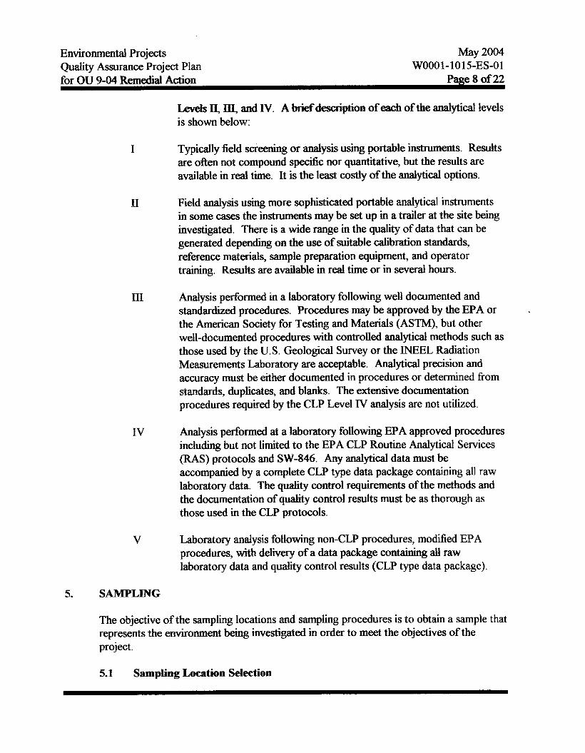
Levels II, IiI, and IV. A briefdescription of each of the analytical levels is shown below:
I Typically field screening or analysis using portable instrumentS. Results are often not compound specific nor quantitative, but the results are available in real time. It is the least costly of the analytical options.
II Field analysis using more sophisticated portable analytical instruments in some cases the instruments may be set up in a trailer at the site beiig investigated. There is a wide range in the quality of data that can be generated depending on the use of suitable calibration standards, reference materials, sample preparation equipment, and operator training. Results are available in real time or in several hours.
III
N
V
Analysis performed in a laboratory following well documented and standardized procedures. Procedures may be approved by the EPA or the American Society for Testing and Materials (ASTM), but other well-documented procedures with controlled analytical methods such as those used by the U.S. Geological Survey or the INEEL Radiation Measurements Laboratory are acceptable. Analytical precision and accuracy must be either documented in procedures or determined from standards, duplicates, and blanks. The extensive documentation procedures required by the CLP Level N analysis are not utilized.
Analysis performed at a laboratory following EPA approved procedures inchding but not limited to the EPA CLP Routine Analytical Services (RAS) protocols and SW-846. Any analytical data must be accompanied by a complete CLP type data package containing all raw laboratory data. The quality control requirements of the methods and the documentation of quality control results must be as thorough as those used in the CLP protocols.
Laboratory analysis following non-CLP procedures, modified EPA procedures, with delivery of a data package containing all raw laboratory data and quality control results (CLP type data package).
5. SAMPLXNG
The objective of the sampling locations and samphg procedures is to obtain a sample that represents the environment being investigated in order to meet the objectives of the project.
5.1 Sampling Location Selection
Environmental Projects May 2004
for OU 9-04 R e m d Action Page 9 of 22 Quality Assurance Project Plan WOO0 1 - 101 5-ES-0 1
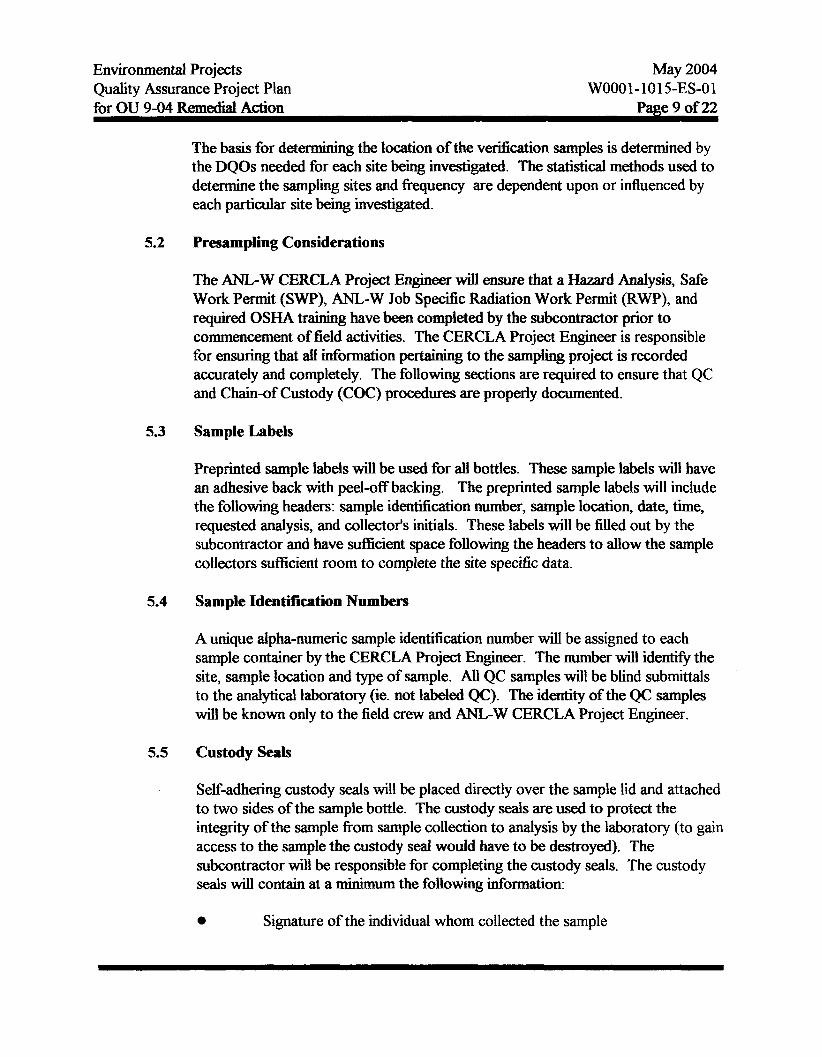
The basis for determining the location of the verification samples is determined by the DQOs needed for each site being investigated. The statistical methods used to determine the sampling sites and frequency are dependent upon or influenced by each particular site being investigated.
5.2 Presrunplhg Considerations
The ANL-W CERCLA Project Engineer will ensure that a Hazard Analysis, Safe Work Permit (SWP), ANL-W Job Specific Radiation Work Permit (RWP), and required OSHA training have been completed by the subcontractor prior to commencement of field activities. The CERCLA Project Engineer is responsible for ensuring that all information pertaining to the samphg project is recorded accurately and completely. The following sections are required to ensure that QC and Chain-of Custody (COC) procedures are properly documented.
5.3 Sample Labels
Preprinted sample labels will be used for all bottles. These sample labels will have an adhesive back with peel-off backing. The preprinted sample labels will include the following headers: sample identification number, sample location, date, time, requested analysis, and collectots initials. These labels will be filled out by the subcontractor and have sufficient space following the headers to allow the sample collectors sufficient room to complete the site specific data.
5.4 Sample Identification Numbers
A unique alpha-numeric sample identification number will be assigned to each sample container by the CERCLA Project Engineer. The number will identifl the site, sample location and type of sample. All QC samples will be blind submittals to the analytical laboratory (ie. not labeled QC). The identity of the QC samples will be known only to the field crew and ANL-W CERCLA Project Engineer.
5.5 Custody Seals
Self-adhering custody seals will be placed directly over the sample lid and attached to two sides of the sample bottle. The custody seals are used to protect the integrity of the sample from sample collection to analysis by the laboratory (to gain access to the sample the custody seal would have to be destroyed). The subcontractor will be responsible for completing the custody seals. The custody seals will contain at a minimm the following information:
0 Signature of the individual whom collected the sample
Environmental Projects Quality Assurance Project Plan
May 2004 WOOO1-1015-ES-01
for OU 9-04 Remedial Action Pme 10 of 22
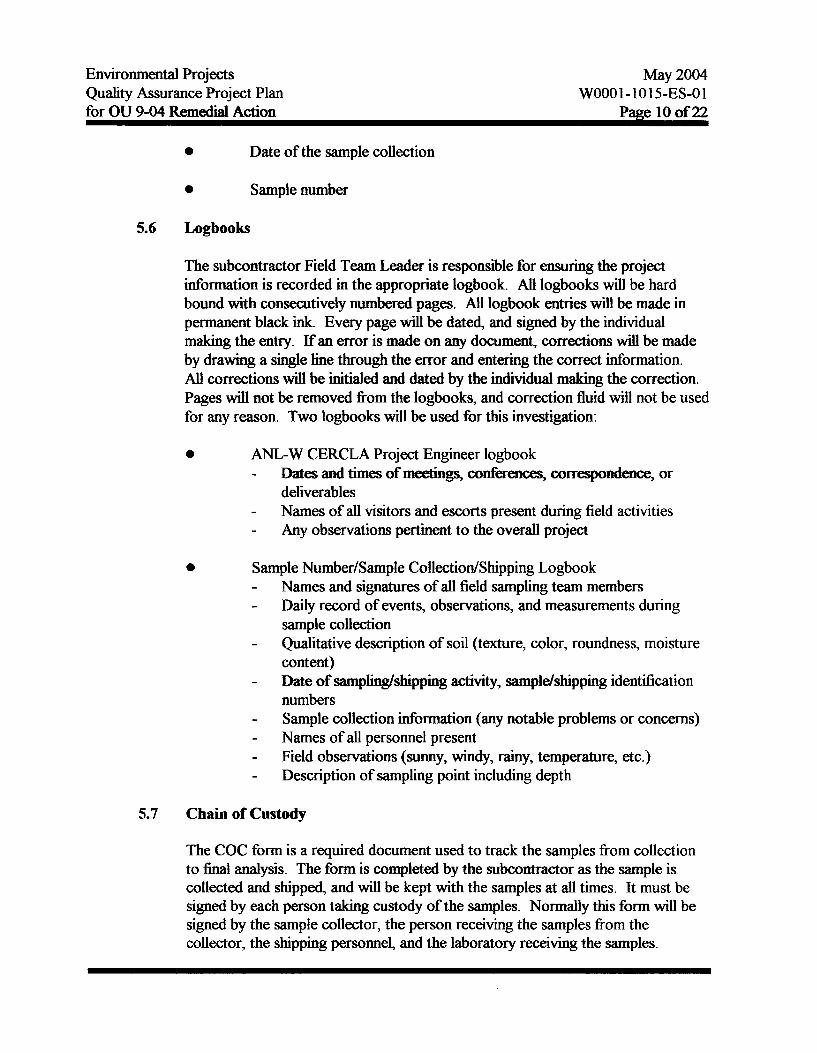
0 Date of the sample collection
0 Sample number
5.6 Logbooks
The subcontractor Field Team Leader is responsible for ensuring the project information is recorded in the appropriate logbook. All logbooks will be hard bound with consecutively numbered pages. All logbook entries will be made in permanent black ink. Every page will be dated, and signed by the individual making the entry. If an error is made on any document, corrections will be made by drawing a single h e through the error and entering the correct information. All corrections will be initialed and dated by the individual making the correction. Pages will not be removed from the logbooks, and correction fluid will not be used for any reason. Two logbooks will be used for this investigation:
0 ANL-W CERCLA Project Engineer logbook - Dates and times of meetings, confkencq correspondence, or
deliverable Names of all visitors and escorts present during field activities Any observations pertinent to the overall project
- -
0 Sample Number/Sample CollectiodShipping Logbook - -
Names and signatures of all field sampling team members Daily record of events, observations, and measurements during sample collection Qualitative description of soil (texture, color, roundness, moisture content) Date of samphg/shipping activity, sampldshipping identiiication numbers Sample collection information (any notable problems or concerns) Names of all personnel present Field observations (sunny, windy, rainy, temperature, etc.) Description of sampling point including depth
-
-
- - - -
5.7 Chain of Custody
The COC form is a required document used to track the samples from collection to final analysis. The form is completed by the subcontractor as the sample is collected and shipped, and will be kept with the samples at all times. It must be signed by each person taking custody of the samples. Normally this form will be signed by the sample collector, the person receiving the samples from the collector, the shipping personnel, and the laboratory receiving the samples.

Environmental Projects May 2004 Quality Assurance Project Plan WOOO1- 10 15-ES-0 1 for OU 9-04 Remedial Adon Page 1 1 of 22
5.8
5.9
5.10
Sampling and Equipment Procedures
T h e n u m b e r a n d t y p e s o f s a m p l e s a n d d K ~ ~ f o r e a c h s a m p l e w i l l be described in the Remedial Action Work Plan. At ANL-W all collection procedures used in the EP section are detailed in the ANL-W Environmental Procedures Manual. Additional Standard Operating procedures (SOPs) used may be those used at the INEEL Sample and Analysis Management Organization. A copy of the ANL-W Environmental Procedures Manual will be supplied upon request.
Sample Equipment Decontamination
The sampling equipment used during the collection of the samples will be decontaminated by the subcontractor prior to and after each sample is collected. The SOPs used for equipment decontamination are listed in the ANL-W Environmental Procedures Manual. A copy of the ANL-W Environmental Procedures Manual will be supplied upon request.
Sample Preservation and Holding Times
Sample preservation and holding times are sample medium and analysis specific. Tables 13 and 14 list preservation methods and holding times for those types of analysis commonly used at ANL-W. If the preservation and/or holding times are not met for a particular sample the sample will be flagged during the data validation process.
6. ANALYTICAL PROCEDURES
Prior to the selection of an analytical laboratory the following must be considered: the laboratory's status and/or certification and the laboratory's acceptance criteria regarding the radioactive content of the samples.
Once a laboratory is selected and approved by ANL-W, all samples will be analyzed utilizing EPA approved methods, American National Standards Institute (ANSI) standard methods, and ASTM or industry accepted methods.
7. CALIBRATION PROCEDURES
All laboratory analysis equipment will be calibrated in accordance to the manuEacturer's recommendations which define the calibration frequency and acceptance criteria. All field equipment (radiological and environmental) used must be calibrated according to the

Environmental Projects Quality Assurance Project Plan
May 2004 WOOO1-1015-ES-01
for OU 9-04 Remedial Action Page 12 of 22
manufacturer's recommendations. Fidd equipment calibration procedures must be documented in the sample log book.
8. DATA REDUCTION, VALIDATION, AND REPORTING
This section describes the data reduction scheme for collected data, the criteria used to evaluate data integrity, the method used for handling outliers, and flow of data from collection through storage of the validated data.
8.1 Data Reduction
Data reduction occurs at two points in the data collection and interpretation process: in the laboratory and following receipt of the data. Data reduction of raw laboratory data will be performed by the laboratory after ANL-W reviews the procedures. Data reduction of the analytical data for interpretation, if required, will occur in conjunction with a Statistician and will be documented in the project report.
8.2 Data Validation
Data validation is the review of measurements and analytical results to confirm that method requirements have been achieved. The primary purpose of data validation is to ensure the legal defensibility of the data. Therefore, data validation to the highest degree possible should be performed on data that may result in a final action of the site. The subcontractor will perform, at a minimum, Level C validation for screening activities and Level B and/or A for verification samples. The procedures for method data validation, including determining outliers and appropriate qualification flags, are in the INEEL Sample and Analysis Management Guides. 13~14~157&16
8.3 Data Reporting
All subcontractor provided analytical packages submitted to ANL-W shall include as a minimum the following:
e Sample receipt and tracking documentation, including identification of the organization and individuals performing the analysis, the names and signatures of the responsible analyst, sample holding time requirements, references to applicable COC procedures, and the dates of sample receipt, extraction, and analysis.
Environmental Projects Quality Assurance Project Plan
May 2004 WOOO1-1015-ES-01
for OU 9-04 Remedial Action Page 13 of 22
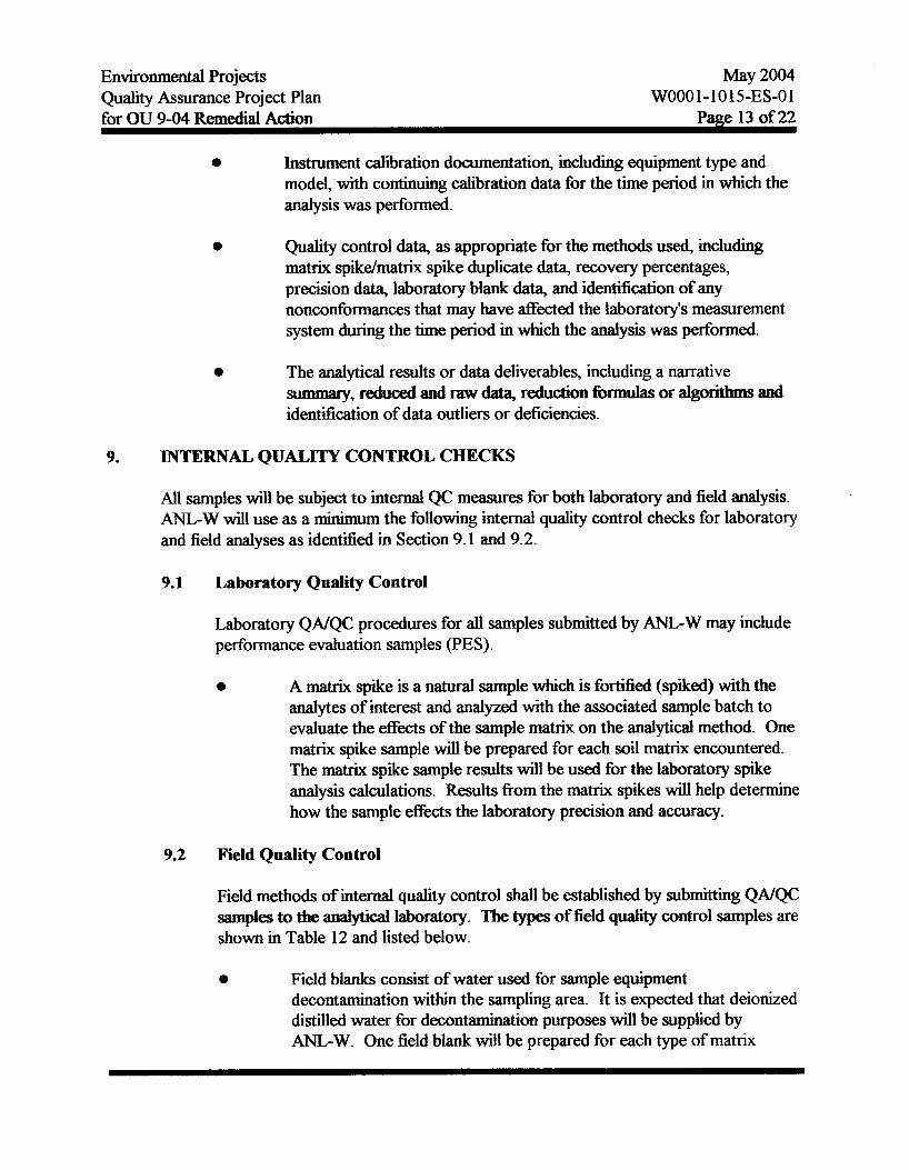
e Instrument calibration documentation, including equipment type and model, with continuing calibration data for the time period in which the analysis was performed.
e Quality control data, as appropriate for the methods used, including matrix spikdmatrix spike duplicate data, recovery percentages, precision data, laboratory blank data, and ident5cation of any nonconformances that may have affected the laboratory's measurement system during the time period in which the analysis was performed.
e The analytical results or data deliverables, including a narrative summary, reduced and raw data, reduction formulas or algorithm and identiiication of data outliers or deficiencies.
9. INTERNAL QUALITY CONTROL CHECKS
All samples will be subject to internal QC measures for both laboratory and field analysis. ANL-W will use as a minimum the following internal quality control checks for laboratory and field analyses as identified in Section 9.1 and 9.2.
9.1 Laboratory Quality Control
Laboratory QNQC procedures for all samples submitted by ANL-W may include performance evaluation samples (PES).
e A matrix spike is a natural sample which is fort34 (spiked) with the analytes of interest and analyzed with the associated sample batch to evaluate the effects of the Sample matrix on the analytical method. One matrix spike sample will be prepared for each soil matrix encountered. The matrix spike sample results will be used for the laboratory spike analysis calculations. Results from the matrix spikes will help determine how the sample effects the laboratory precision and accuracy.
9.2 Field Quality Control
Field methods of internal quality control shall be established by submitting QNQC samples to the analytical laboratory. The types of field quality control samples are shown in Table 12 and listed below.
e Field blanks consist of water used for sample equipment decontamination within the sampling area. It is expected that deionized distilled water for decontamination purposes will be supplied by ANLW. One field blank will be prepared for each type of matrix

Environmental Projects Quality Assurance Project Plan
May 2004 WOO01 - 101 5-ES-0 1
for OU 9-04 Remedial Action Page 14 of 22
encountered. The field blank water will be placed in the sample container fiom the same lot as the other sample containers. Results from the field blank will help determine the level of contamination introduced into the sample fiom ambient conditions during the sampling technique.
e
e
Field duplicates are obtained by collecting two samples at the same sampling point. One field duplicate will be randomly selected from each of the ten sample locations. The analysis of field duplicates reflects the heterogeneity of the natural sampling media. Results from the field duplicates will help determine the effects of sampling precision.
Trip blank samples are used to detect cross contamination of volatiles during shipment. Each sample cooler containing volatiles will contain laboratory prepared volatile samples.
10. PERFORMANCE AND SYSTEMS ASSESSlWENTS
Performance assessments are conducted to independently collect measurement data to determine the accuracy of portions or the accuracy of the total measurement system. System assessments are used to ensure that the QAPjP activities relating to the sampling and analysis of verification samples are performed according to the QAPjP. Performance assessments will be performed in accordance with EPA requirements for Preparing Quality Assurance Project Plans, QAM 005/80, EPA, 1980. Systems assessments are conducted according to ANL-W ESWQA Oversight and Quality Assurance Procedures (Argonne- West Procedures Section 5).
Evaluating the performance of the activities will be the responsibility of the NTD Quality Assurance Representative. System assessments will occur throughout the sampling aspect of the project, while performance assessment activities will commence shortly after the beginning of field activities. Quality-related activities will be assessed to ensure compliance with the QAPjP. Internal inspections will be performed annually for each specific activity. Significant deviations fiom the QAPjP will be brought to the attention of the CERCLA project manager and NTD Quality Assurance Representative, and corrective actions will be taken as required by AWP 4.7 Nonconformance Reporting System. Any discrepancies noted during an assessment that cannot be immediately corrected to the satisfaction of the assessor shall be documented by report (Procedure Number III-3).
10.1 Performance Assessments
Field performance assessments shall be used to determine the status of the sampling operation. To accomplish this task, sample records, sampling equipment,
Environmental Projects Quality Assurance Project Plan for OU 9-04 Remedial Acfiun
May 2004
Patze 15 of 22 WOO01 -101 5-ES-0 1
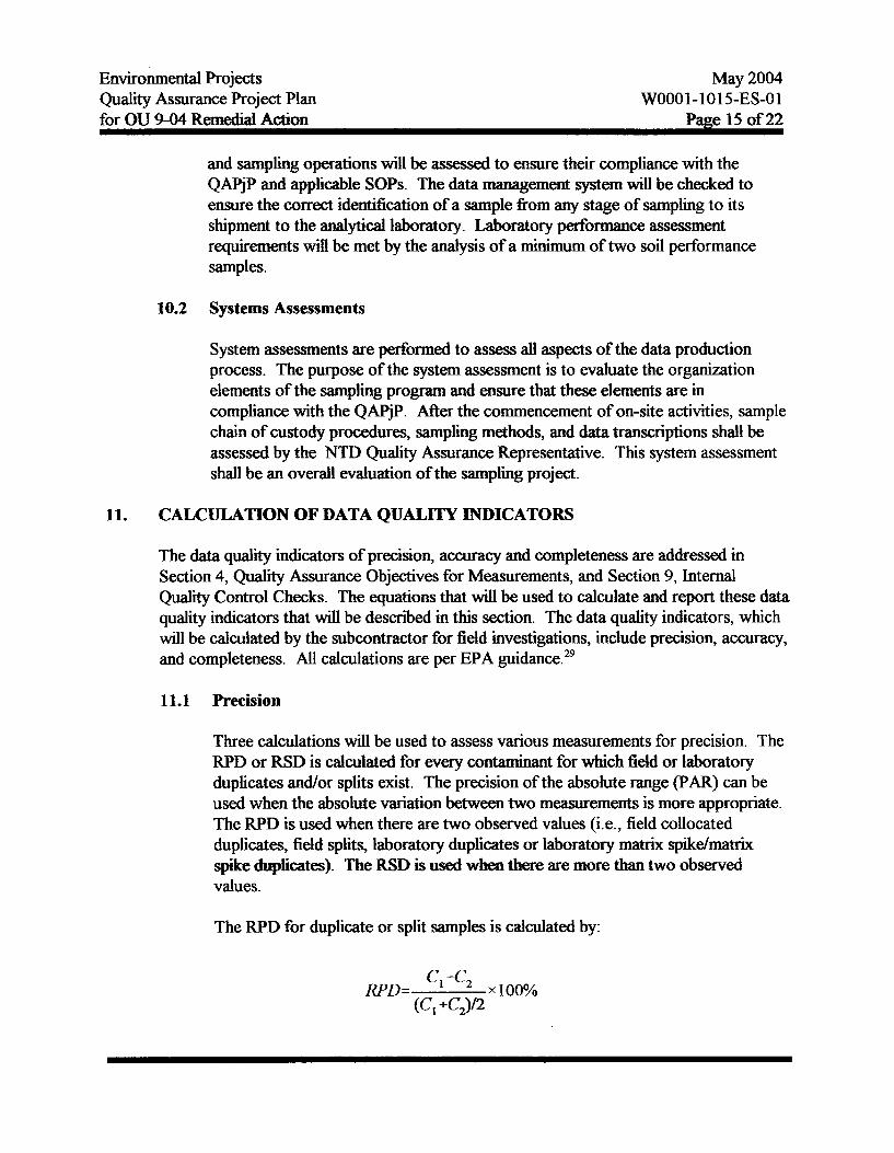
and sampling operations will be assessed to ensure their compliance with the QAPjP and applicable SOPS. The data management system will be checked to ensure the correct identification of a sample fiom any stage of sampling to its shipment to the analytical laboratory. Laboratory performance assessment requirements will be met by the analysis of a minimum of two soil performance samples.
10.2 Systems Assessments
System assessments are performed to assess all aspects of the data production process. The purpose of the system assessment is to evhate the organization elements of the sampling program and ensure that these elements are in compliance with the QAPjP. After the commencement of on-site activities, sample chain of custody procedures, sampling methods, and data transcriptions shall be assessed by the NTD Qual~ty Assurance Representative. This system assessment shall be an overall evaluation of the sampling project.
11. CALCULATION OF DATA QUALITY INDICATORS
The data quality indicators of precision, accuracy and completeness are addressed in Section 4, Quality Assurance Objectives for Measurements, and Section 9, Internal Quality Control Checks. The equations that will be used to calculate and report these data quality indicators that will be described in this section. The data quality indicators, which will be calculated by the subcontractor for field investigations, include precision, accuracy, and completeness. All calculations are per EPA guidance.29
11.1 Precision
Three calculations will be used to assess various measurements for precision. The RPD or RSD is calculated for every contaminant for which field or labomtory duplicates and/or splits exist. The precision of the absolute range (PAR) can be used when the absolute variation between two measurements is more appropriate. The RPD is used when there are two observed values @e., field collocated duplicates, field splits, laboratory duplicates or laboratory matrix spikdmatrjx spike dq&cates). The RSD is used when there are more than two observed values.
The RPD for duplicate or split samples is calculated by:
Environmental Projects Quality Assurance Project Plan
May 2004 WOO0 1 - 101 5-ES-0 1
for OU 9-04 Remedial Action Page 16 of 22
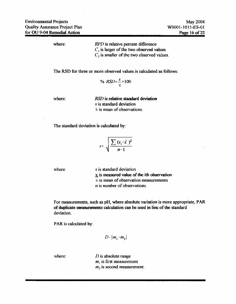
where: RPD is relative percent difference C, is larger of the two observed values C, is smaller of the two observed values.
The RSD for three or more observed values is calculated as follows:
where: RSD is relative standard deviation s is standard deviation 2 is mean of observations.
The standard deviation is calculated by:
where: s is standard deviation xi is m d value of the ith observation R is mean of observation measurements n is number of observations.
For measurements, such as pH, where absolute variation is more appropriate, PAR of duplicate m-ammnmts Calculation can be used in lieu of the standard deviation.
PAR is calculated by:
where: D is absolute range m, is first measurement m, is second measurement.

Environmental bojects Quality Assurance Project Plan
May 2004 WOO01 - 101 5-ES-01
for OU 9-04 Remedial Action Page 17 of 22
Assuming that the variances follow a chi-squareti distribution, the precision obtained will be based upon the number of duplicate and/or split samples, with a confidence of I-a as shown by:
where: c4 is variance to be estimated s is standard deviation n is number of duplicate or split pairs J is chi-squared value.
The number of duplicate and/or split samples recommended by the EPA for field QC samples is shown in Table 12.
11.2 Accuracy
Two calculations will be used to assess laboratory accuracy: percent recovered ('YoRec) of the MS and %Rec of known andor blind Laboratory Control Samples 0.w. The %Rec of the MS is calculated by:
Ci-Co 'YO Rec=r x 100%
where: %Rec is percent recovery Ci is concentration of spiked aliquot C, is concentration of unspiked aliquot C, is the actual concentration of the spike added.
The 0/0Rec of a known and/or b h d LCS or a standard reference material (SRM) is calculated as:
% Rec=- cm x 100% csrm
where Y&ec is percent recovery Cm is measured concentration of the SRM or the LCS
Environmental Projects May 2004 Quality Assurance Project Plan WOOO1-1015-ES-0 1 for OU 9-04 Remedial Action Page 18 of 22
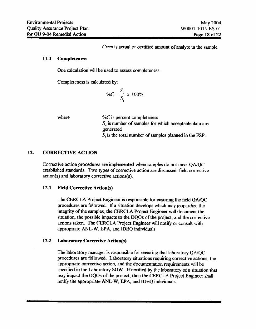
Csnn is actual or certified amount of analyte in the sample.
11.3 Completeness
One calculation will be used to assess completeness
Completeness is calculated by:
s a
st %C =- x 100%
12.
where
CORRECTIVE ACTION
YoC is percent completeness Sa is number of samples for which acceptable data are generated S, is the total number of samples planned in the FSP.
Corrective action procedures are implemented when samples do not meet QNQC established standards. Two types of corrective action are discussed: field corrective action(s) and laboratory corrective actions@).
12.1 Field Corrective Aetion(s)
The CERCLA Project Engineer is responsible for ensuring the field QNQC procedures are followed. If a situation develops which may jeopardize the integrity of the samples, the CERCLA Project Engineer will document the situation, the possible impacts to the DQOs of the project, and the corrective actions taken. The CERCLA Project Engineer will noti@ or consult with appropriate ANL-W, EPA, and IDEQ individuals.
12.2 Laboratory Corrective Action(s)
The laboratory manager is responsible for ensuring that laboratory QNQC procedures are followed. Laboratory situations requiring corrective actions, the appropriate corrective action, and the documentation requirements will be spedied in the Laboratory SOW. Ifnotified by the laboratory of a situation that may impact the DQOs of the project, then the CERCLA Project Engineer shall notify the appropriate ANL-W, EPA, and IDEQ individuals.
Environmental Projects Quality Assurance Project Plan
May 2004 WOOO1-1015-ES-01
for OU 9-04 R d d Action Page 19 of22
13. RECORD KEEPING
Records that furnish documentary evidence of quality shall be specified, prepared, and maintained. Records shall be legible, identifiable, and retrievable. Records shall be protected against damage, deterioration, or loss. The CERCLA Project Engineer shall be responsible for the control and retention of records generated during this project.
14. QUALITY ASSURANCE REPORTS
As previously noted in Section 10 of this QAPjP, the activities associated with the collection of samples in accordance with the FSP shall be routinely subjected to assessment through pefiormance assessments and systems assessments. At the completion of the investigation the NTD Quality Assurance Representative shall sumfnarize all such activity in a report to the CERCLA Project Engineer. The report shall identifl all open action items, shall iden* and analyze any adverse quality trends, and based on an evaluation of the data validation summary reports from the investigation, shall include an assessment of the overall adequacy of the total measurement system with regard to the Quality Assurance Objectives for Measurements discussed in Section 4 of this QAPjP.
15. PREVENTATIVE MAINTJCNANCE
Preventative maintenance items and or a list of spare parts that are required to perform the remedial action activities in a timely manner are limited to those items relating to the planting and harvesting of plants for this project. These preventative maintenance items include, the manufacturers specified lubrication fiequency for the bearings and sheaves of the equipment, regular engine oil changes, air, and fuel filters for engines.
16. REFERENCES
1. Envirmumiml Protection Agency, Requirements for Qwiijy Assurance Project Plans, QAR-5, 1997.
2. Environmental Protection Agency, Preparing Perf'ect Project Plans, EPA/600/9- 89/087, October 1989, p. v.
3. State of Idaho, Department of Health and WeSare; U. S. Environmental Protection Agency; and U.S. Department of Energy Field Office, Idaho; Action Plan for ImpZementation of the Federal Facility Agreement mrd Consent Order for the Idaho NationaZ Engzneering Laboratory, December 199 1, pp. 8- 1 5.
4. Environmental Protection Agency, Data QuaZiv Objectiues for Remedial ReJponse Activities: DeveZopment Process, EPA/54O/G-87/003, March 1987, pp. 3-6 - 3-9.

Environmental Projects May 2004 Quality Assurance Project Plan WOO01 -1 0 15-ES-0 1 for OU 9-04 Remedial Action Page 20 of 22
5 .
6.
7.
8.
9.
10.
11.
12.
13.
14.
15.
16.
17.
Envi romtaI Protection Agency, PreFation Ai& for the Development of Category 111 Quality Assurance Project Plans, EPA/600/8-91/005, February 1991, p. 17.
Environmental Protection Agency, Data Quality Objectives for Remedial Re~pcmse Activities: Devebpment Pruces, EPA/540/G-87/003, March 1987, pp. 4-17 - 4-18.
Environmental Protection Agency Contract Laboratory Program, Skztement of W d J b r I-ic Ana&sis - Midti#&, Multi€oncentrution, ILM02.0, March 1990.
Environmental Protection Agency Contract Laboratory Program, Statement of Wo&* Orgrmic Amlysis - MultiMda, Multi-Cuncentration, OLMOI. 0, March 1990.
Environmental Protection Agency, Soil Sampling Qmlity Assurance User’s a i & , EPA/600/8-89/046, March 1989, p. 104
Environmental Protection Agency, Guidance for Lkta Useability in Risk Assessment - Interim Final, EPA/540/G-90/008, October 1990, p. 84.
Environmental Protection Agency, Guidance for Data Usabiity in Risk Assessment, EPA/540/G-90/008, October 190, pp. 57-58.
INEEL Sample and Analysis Management, “Inorganic Analyses Data Validation”, GDE- 12 1 (current revision)
INEEL Sample and Analysis Management, “Validation of Volatile Organic Data using G a s Chromatography/Mass spectrometry”, GDE-239 (current revision)
INEEL Sample and Analysis Management, “Validation of Gas and Liquid Chromatographic Organic Data”, GDE-240 (current revision)
INEEL Sample and Analysis Management, “Radioanalytical Data Validation”, GDE-205 (current revision)
INEEL Sample and Analysis Management, “Levels of Analytical Data Validation”, GDE-7003 (current revision)
Environmental Protection Agency, Samplers guide to the Contract Laboratory Program, EPA/540/P-90/006, December 1990, p. 12.

Environmental Projects May 2004 Quality Assurance Project Plan WOO0 1-10 15-ES-01 for OU 9-04 Remedal Action Page 21 of 22
18.
19.
20.
21.
22.
23.
24.
25.
26.
27.
28.
G.A Harris, EG&G Idaho Inc. Environmental Restoration Program Data Integrity Review Committee,, Development and Support material for W~t ing Sampling and Analysis R e m s , October 30, 1989, "Guidance for Determining Field Precision and Number of Sample, Revision 2, '' Section 6.1, pp. 2-4.
Environmental Protection Agency, Soil Sampling Quality Assurance User's Guide, EPA/600/8-89/046, March 1989, p. 105.
Environmental Protection Agency, Soil Sampling Quality Assurance User's Guide, EPA/600/8-89/046, March 1989, p. 105.
Environmental Protection Agency, Quality Assurance Project Plan for Characterization Sampling and Treatment Tests Conducted for the Contaminated Soil andDebris (CSD) Program, November 8, 1990, p. 4-7.
American Society for Testing and Materials, 1992 Annual Book of A S W St&&, Section 1 1 : Water and Environmental Technology, Volume 1 1.03 : Atmospheric Analysis; Occupational Safe ty and Health, ASTM Designation D- 1193-91, 1992, pp. 1-3.
Environmental Protection Agency, Soil Smnpling and Analysis for Volatile Organic Compounds, EPA/540/4-91/001, February 1991, p. 9.
Environmental Protection Agency, Performance Evaluation Samples, 0938MEX91, September 1991, pp. 1-2.
Environmental Protection Agency, Dafa Quality Objectives for Remedial Resjmme Activities: &vebpnent Process, EPA/540/G-87/003, March 1987, p. 4-18.
Environmental Protection Agency Contract Laboratory Program, Statement of Work for Organic Analysis - Multi-Media, Multi-Concentration, OLMOI. 0, March 1990, pp. C-1 - C-10.
Environmental Protection Agency, Methods for the Determination of Organic compMlt2ds in Drinking Water, EPA/600/4-88/039, December 1988, pp. 285-323.
Environmental Protection Agency, Data Quality Objectives for Remedial Resporrse Activities - DevelopJnenf l'ruces, EPN54O/G-87/003, March 1987, pp- 4-9 - 4-13.

Environmental Projects M a y 2004 Quality Assurance Project Plan WOOO1-1015-ES-01 for OU 9-04 Remedial Action Page 22 of 22
29.
30.
31.
32.
33.
34.
35.
36.
Environmental Protection Agency, Prepation Aids for the Development of Category I n Quality Assurance Prqject Plans, EPA/600/8-91/005, February 1991, pp- 43-45.
DOE-ID, Qmlity Assurance Project P h for Waste Area Groups I , 2, 3, 4, 5, 6, 7, 10 arui Inactive Sites, DOE/ID-10587, Rev. 7, U.S. Department of Energy Idaho Operations OEce, Idaho Falls, Idaho, 2002.
ETAS Corporation, Quality Assurance Project Plan for the slua'ge removal and
1993. warte ~h&f i&h for the EBR-II LeQch Pit, W7630-0005-ES-00 Sqt- 6,
Golder and Associates Inc., Smnpling arui Analysis Plan for Argonne National Laboratory West Background Soil, October 1993.
ANL-W Wee of Quality As-, Qualify Assurance Program, WOO0 1-0929- QM, latest revision.
ANL-W, Argonne ProceduresMmal, Rev. 25, March 14, 1994.
ANL-W Reactor Program S&ces, Management P h , WOO01 -0936-AP7 July 7, 1993.
W - W , ESH/QA Oversight and Quality Assurance Procedures, Procedure Number III-3, May 5, 1994.

ATTACHMENTS

ATTACHMENT A QAPjP TABLES

TaMe 1. 3-90 SOW CLP Volatile Organic Target Compound List
Toluene
chl-
Eulylbenzene
styreoe
XYI- (tow
compolmd CAS Numbes CRQL QcLimils
w* Lowsoil Medsoa war5 wrtpr sOil%&c soil olm OtgArg) %Rec RPD RPD
a- 07487-3 10 10 1200
Bmmomettiaoe 7443-9 10 10 1200
108-88-3 10 10 1200 76-125 13 59-139 21
108-90-7 10 10 1200 75-130 13 59-139 21
100-414 10 10 1200
100-42-5 10 10 1200
1330-20-7 10 10 1 200
V i c h h i & 75-01-4 10 10 1200
Chloroetbam 75-00-3 10 10 1200
Methylenechlaide 75-09-2 10 10 1200
Acetone 67-64- 1 10 10 1200
carbon- 75-1 5 4 10 10 1200
1,l-a- 75-35-4 10 10 1200
1,l-DirmaOethme 75-363 10 10 1200 61-145 14 59-172 22 I I
1,243- (U) 540-594 10 10 1200
chloroform 67-66-3 10 10 1200
1pDichlOroethane 107-06-2 10 10 1200
2-Butawoe 78-93-3 10 10 1200
1,1,1 -T&oroethane 71-556 10 10 1200
56-23-5 10 10 1200
Bnxnodi- 75-27-4 10 10 1200
1243- 78-87-5 10 10 1200
cia-1,3-%- 10061426 10 10 1200
T r i C h I d 79-01-6 10 10 lz00 71-120 14 62-137 24
Dibnrmochlonmnethane 124-48-1 10 10 1200
1,1,2-TrichIoroe&a~e 79-00-5 10 10 1200
BeaLmle 71-43-2 10 10 1200 76-127 11 66-142 21
10061-02-6 10 10 1200
75-25-2 10 10 1200 I I I 1
4,Mdh$-2-P- 108-10-1 10 10 1200
Z-HeXawne 594-78-4 10 10 1200
TebachIoroethene 127-18-4 10 10 1200
I 79-34-5 1 10 I 10 I 1200 I I I I
A- 1

Table 2. 3-90 SOW CLP Semivolatile Organ Target Compound List
I
Hexachlorcht&me 87-68-3 10 330 10000 --- 59-50-7 10 330 10000 23-97 42 26103 33
2-FA- 91-57-6 10 330 10000
H e d - 77474 10 330 10000
2 , 4 , 6 - T d ~ q h 1 0 l 88-062 10 330 10000
2,4,5-Tnchlorophewl 95-95-4 10 1700 50000
2chlomnaphthalene 9 1-58-7 10 330 10000
2-N-e 88-74-4 50 1 700 50000
131-11-3 10 330 10000
10 330 10000
2,6-Dinitrotdueoe 606-20-2 10 330 10000
3-Nrtroaniline 99-09-2 50 1700 50000
AcenapMheoe 83-32-9 10 330 10000 46-118 31 31-137 19
A-2

Table 2. 3-90 SOW CLP Semivolatile Organ Target Compound List (cont)
Din-
Benzo(b)Buoraothene
w f l -
Compound
117-840 10 330 loo00
205-99-2 10 330 loo00
207-08-9 10 330 loo00
2,4-- 51-28-5 50 1700 50000
100-02-7 50 1700 50000 10-80 50 11-1 14 50
DitKnmb 13264-9 10 330 loo00
2,4-Dinitrdotrwre 121-14-2 10 330 loo00 24-96 38 28-89 47
Diethytphthptte 84-66-2 10 330 1ooM)
Kill-* 7005-72-3 10 330 loo00
Flu- 86-73-7 10 330 loo00
4 - N i 1oo .016 50 1700 50000
4,6-LXnk+2- 534-52-1 50 1700 50000
N - N v 86-30-6 10 330 loo00 I
4 - w 101-55-3 10 330 loo00
Hexachlombaaene 118-74-1 10 330 loo00
Penfachlorophenol 87-86-5 50 1700 5oo00 9-103 50
Ph- 85-01-8 10 330 loo00
Ardhracene 12&12-7 10 330 loo00
carbazole 86-744 10 330 loo00
17-109 3 Din-butyfphltndnte 84-74-2 10 330 loo00
Fluorantfieoe 206-64-0 10 330 loo00
pyrene 12940-0 10 330 loo00 26-127 31 35-142 36
8568-7 10 330 loo00
3,3'-Did&dine 91-941 10 330 loo00
56-55-3 10 330 loo00
21841-9 10 330 loo00
I 191-24-2 330 I I I
A-3

Table 3. 3-90 SOW CLP Pesticide Organic Targd Compound List
I
W-BHC 319-85-7 0.05 1.7 I I I I delta-BHC 319-8643 0.05 1.7
g a m m a - B H C W ) 58-89-9 0.05 1.7 56-123 15 &in 50
Heptachlor 7644-8 0.05 1.7 40-131 20 35-130 31 II I I I I 1 I
30940-2 0.05 1.7 40-120 22 34-132 43
1024-57-3 0.05 1.7 I I
Endosulfan1 959-98-8 0.05 1.7
Dieldrin 60-57-1 0.10 3 3 52-126 18 31-134 38
4,4'-DDE 72-55-9 0.10 3 3
Endrin 72-urx 0.10 3 3 56-121 21 42-139 45
Endosullgnll 33213-65-9 0.10 3 3
4,4'-DDD 72-54-8 0.10 3.3
Endosulfan sulfaie 103 147-8 0.10 3.3
4,4'-DDT 50-29-3 0.10 3.3 38-127 n 23-134 50
Me(hyl0- 72-43-5 050 17.0
Endrinkelone 53494-70-5 0.10 3 3
II -- 1 7421-36-3 I 0.10 I 3 3 I ~~ I I alphachlordane 5103-71-9 0.05 1.7
gammachlordane 5103-74-2 0.05 1.7
Toxaphene 8001-35-2 5.0 170.0
Mor-1016 12674-11-2 1.0 33.0
Aroclor-I22 1 11 10628-2 20 67.0
Mor-1232 11 141-165 1 .o 33.0
M o r - 1242 53469-216 1 .o 33.0
Mor-1248 12672-296 1.0 33.0
1 1109769-1 I 1.0 1 33.0 I I I Aroclor 1260 11096-82-5 1 .o 33.0 I I I
A-4

Table 4. 3-90 SOW CLP inorganic Target A-e List
I 7429-90-5 I -- 7440-360 60
Arsenic 7440-38-2 lo
7440-43-9 5
ll tal- I I
copper 7440-50-8 25
h 7439-89-6 100
Lead 7439-92-1 3
M- 7439-95-4 5000
Manganese 7439-%-5 15
Mercury 7439-974 0.2
I 778249-2 I 5
silvex 7440-224 10 I sodium 7440-23-5 5000
Thallium 7440-28-0 10
Vaoadium 7440-62-5 50
zinc 7440-664 20
cyanide I I 10
A-5
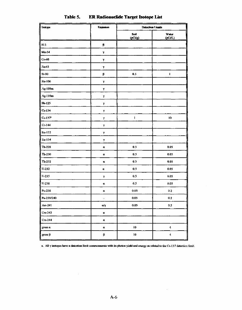
Table 5. ER Radioaaetide Target Isotope List
A-6

Table 6. EPA Method 524.2 Target Anme List
A-7
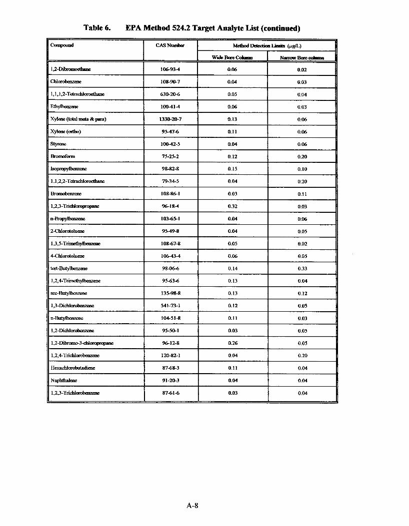
Table 6. EPA Method 524.2 Target Analyte List (continued)
MeiilodIkbedioe- (pen)
WideBore- NnoarBrrecoka
1 2 - w 106-934 0-06 0.02
ull- 108-90-7 0.04 0.03
1,1,1,2-T&add~~&h~ 630-20-6 0.05 0.04
100414 0.06 0.03
xyl-(d-¶) 1330-2&7 0.13 0.06
Xyl-(&) 95-47-6 0.11 0.06
styrene 1 OO42-5 0.04 0.06
0.12 I 0.20
I = W Y - 98-82-8 0.15 0.10
1,1,2,2-T&i~hI0~1dh1e 79-34-5 0.04 0.20
B I - O f l l h 108-86-1 0.03 0.11
1,2,3-Triehlompropaae %-1M 032 0.03
n-- 10365-3 0.04 0.06
2Chl~llIeae 95-49-8 0.04 0.05
108-67-8 0.05 0.02
kert-Butylbenzene 98-066 0.14 0.33
I 1,2,4-T- 95-63-6 0.13 0.04 I
135-98-8 0.13 0.12
0.05 I 0.12
n-Butyibememe 104-51-8 0.11 0.03
12-DichlorObenzme 95-50-1 0.03 0.05
9612-8 026 0.05 ' 1,2-Dibmmo-3- 1,2,4-Tncld- 120-82- 1 0.04 0.20
Hexachlorobutadiene 87-68-3 0.11 0.04
NapMbal- 9 1-20-3 0.04 0.04
1,23-T- 87-61-6 0.03 0.04
A-8
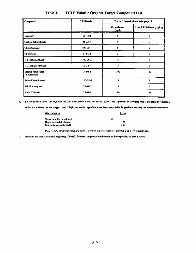
Table 7. TCLP Volatile Organic Target Compound List
Gmmdraater WL)
E%e5?ed 71-43-2 5 5
CarbOaT- 56-23-5 5 5
C h l W 108-!20-7 5 5
morofam 6746-3 5 5
1,Z-Dichloroethsne 10746-2 5 5
1,l -Did-& 75-35-9 5 5
MewEthy lK- 78-93-3 100 100 (2-but;mone)
127-18-4 5 5
T r i c h l d y l a ~ ’ I 5 I 5 79614 I 10 I 10 I vinyl chloride I 75614
SW846 Method 8240. ?be PQLS forthe Zero Headspace Extract, Method 1311, will vary depending onthe waste type as described m footnote 2.
SoilPQLsarebasedmwetv+gk ~ ~ a r e ~ ~ t h o s e W ~ ~ f 0 r ~ a a d r n a y m t ~ b e ~
FaaOr other Matrices: - Water miscible liquid waste 50 H i g b - l e v d S o i l B t ~ 125 Non-water miscible waste 500
PQL = (PQL for groundwater x [Factor]). For non-aqueous samples, the factor is on a wet-weight basis.
Precision and accuracy criteria regardiog MSMSD for these compounds are the same as those specified on the CLPtable.
A-9
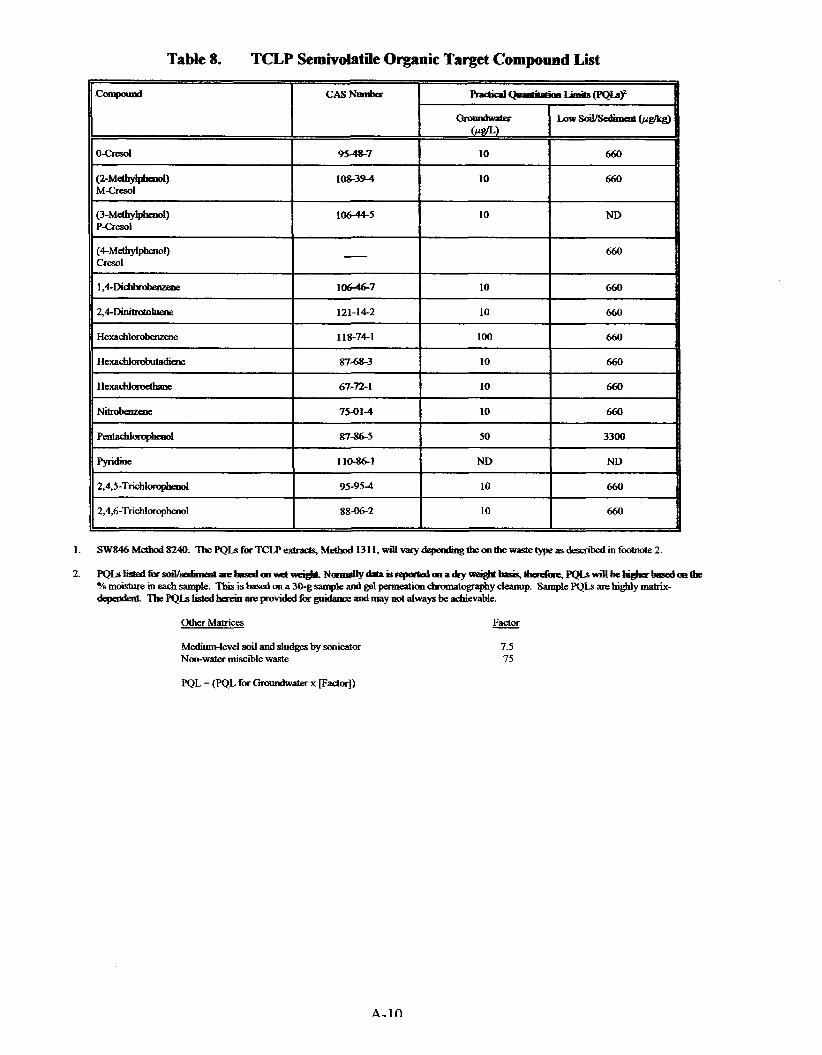
Table 8. TCLP Semivolatile Organic Target Compound List
1.
2.
660 I 10 I (3-M&-I) 10644-5 10 ND Pcresol
I - I 660
I I I
1,4-Di- I 106467 I 10 I 660 I 2,4-Diom;oto Lueoe I 121-14-2 I 10
Medium-level soil and sludges by sonicator Non-water miscible waste
PQL = (PQL for Gnnmdwatax p3ctor])
A-1 n
7.5 75

Table 9. TCLP Metats Target Andyte List
1. F u n a c e ~ a r e ~ i n p p ~ r a ” ‘ . toQheiadadively~pIssma~CP)melhod6010. Merapymetttodsarecold vapor atomic absorption and differ between matrices (the soil method number is m parentheses). After the TCLP extraction. CLP methd maybeusedforsampleprepadonandanalytedetemrinati OR
2. RQL-ReqriredQtu&a&m Limh Tbgelewls-thatt&audyteswillbc&ectedata99%cm6demxlhnit TheseRQtsareone order of mapdude below the regulatay adon limits. Individual iostrUment detection limits (IDLs) must be a factor of 2 below the RQL for &analytequ&imdbythat~
3. Precision aiteria must be satisfied for TCLP extracts and the digestates ERD-SOW-107 defmes criteria
4. A c a n a c y r e a w e r e ! s ~ b e b a s e d ( m t h e p o s l ~ ~ , .. spikes ~ ~ s a n p l e s s s a t l a l s o b e l s e d t o l l s s g a a x n a c y andmust recover within these limits.
5.
6.
Extract generated using TCLP Method 13 11
Some solid matrices require digestidpqwation methods that are not listed (e.&, city waste may require methcd 3040).
A-1 1
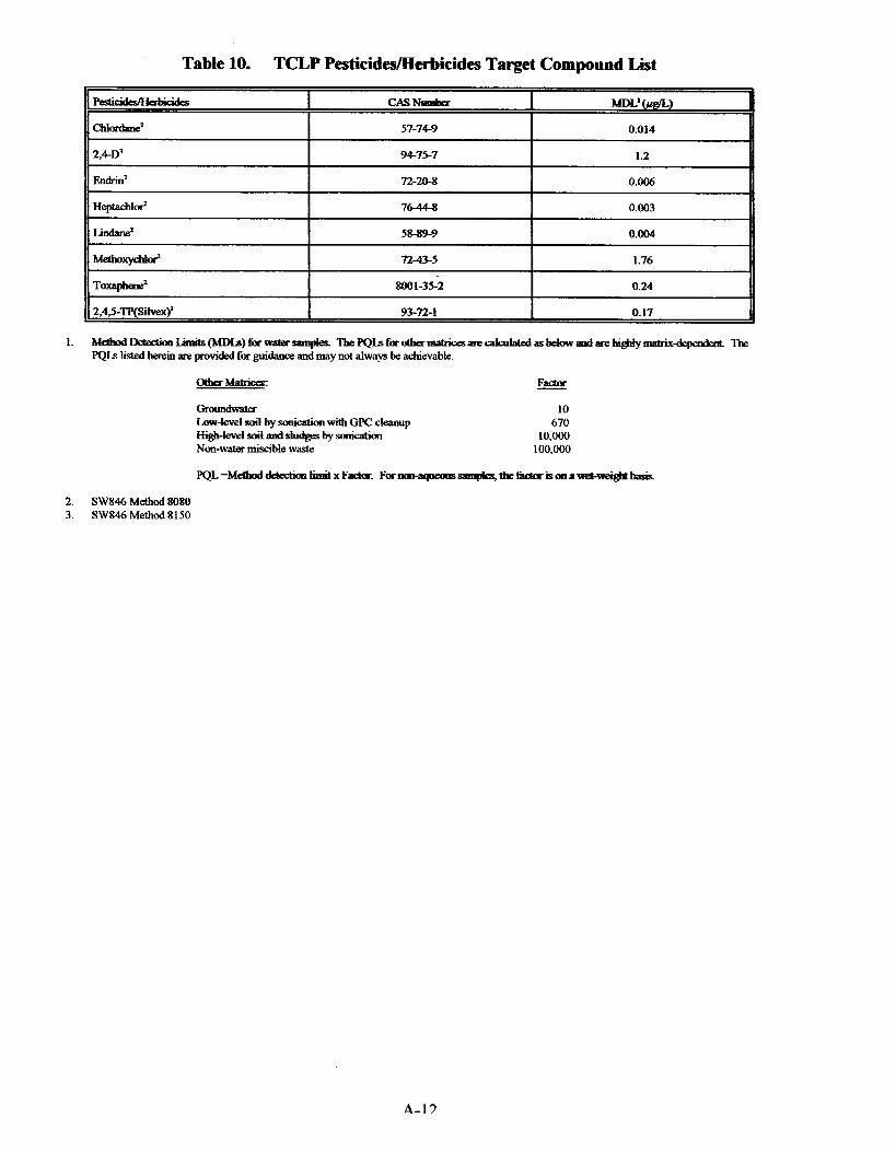
Table 10. TCLP PesticidedHerbkides Target Compound List
~~
Endrin' 7220-8 0.006
76-44-8 0.003
Lindane' I 58-89-9 I 0.004
2,4,5-Tf'(Sikx~ I 93-72-1 I 0.17
10 670
10,Ooo 100,000
2. SW846 Method 8080 3. SW846 Method8150
A-1 3
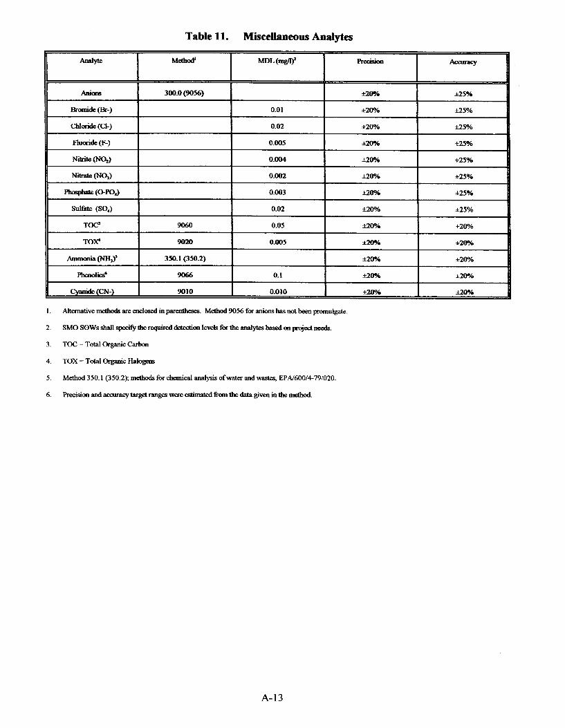
Table 11. Miscellaneous Antllytes
1.
2.
3.
4. TOX=TotalOrganicHabgens
5 .
6.
Alternative methods are enclosed m parentheses. Methcd 9056 for anions has not been promulgate
SMO SOWS shall specify the required detedion l a d s forthe analytes based on Pmjed d.
TOC = Total Organic Carbon
Method 350.1 (350.2); methods for chemical analysis ofwater and wastes, EPA/600/4-79/020.
Precisionandacauacytargetrangeswere estimatedfkmthe data giVfal in the method
A-13

f
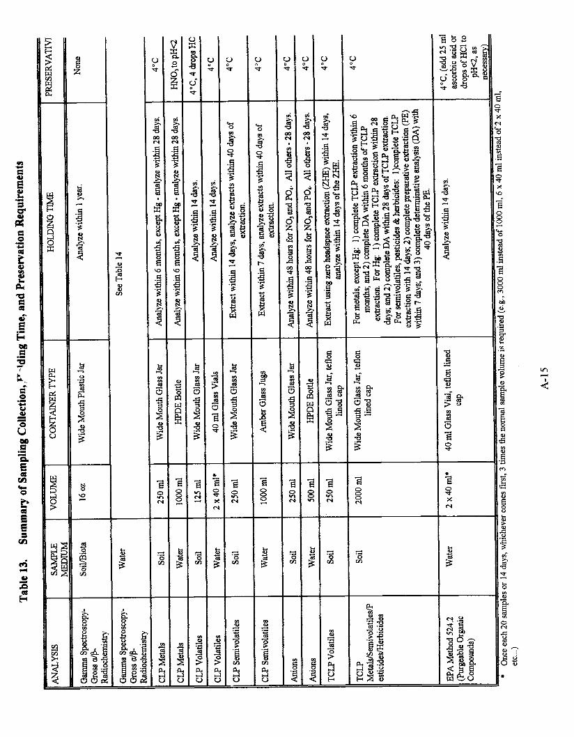
Y d

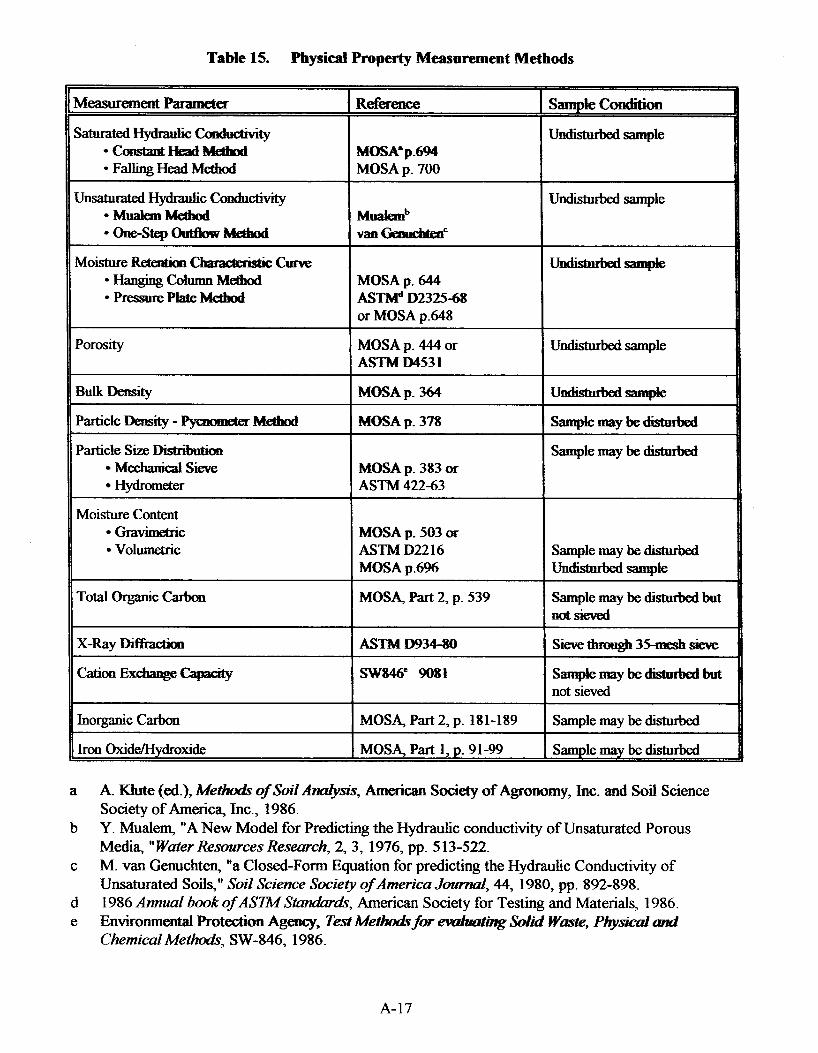
Table 15. Physid Property Measurement Methods
I 1 . . MoistureRete~shC- curve
*HangingCOlUmnMeqhod MOSA p. 644 *pressurePkteMethod Asm D2325-68
or MOSA p.648
Porosity MOSA p. 444 or Undisturbed sample ASTha M531
Bulk Density MOSAp. 364
Particle Density - pygmmeter Meahod MOSA p- 378 s w n r a v b e -
Particle Size Disbibution Sample may be dtisturbed Mechauical Sieve Hydrometer ASTM 422-63
MOSA p- 383 or
Moisture Content * G r a M c
Volumetric MOSA p- 503 oh ASTM D22 16 MOSA p.6%
Sample may be dishrrbed Undisturbed sample
Total Organiccarbon MOSA, Part 2, p. 539 Sample may be disturbed but notsieved
x-Ray DifEaah AsTlWm34%0 Sieve ttmmgh 35-mesh sieve
Cation Exchange Capacity SW846" 9081 S*=Yt=- but not sieved
11 I 1-- I MOSA, Part 2, p. 181-189 I Sample maybe disturbed I I I MOSA, Part 1, p- 91-99 I Sample may be disturbed
A K€ute (ed.), Methuds of Soil Analysis, American Society of Agronomy, Inc. and Soil Science Society of America, Inc., 1986. Y. Mualem, "A New Model for Predicting the Hydraulic conductivity of Unsaturated Porous Media, "Water Resources Research, 2,3, 1976, pp. 5 13-522. M. van Genuchten, "a Closed-Form Equation for predicting the Hydraulic Conductivity of Unsaturated Soils," Soil Science Society of America Journal, 44, 1980, pp. 892-898. 1986 AnnuaZ book of ASK44 St&&, American Society for Testing and Materials, 1986. Environmental Protection Agency, Test for eduafhg Soiid W e , Physical and ChemicaIMethods, SW-846, 1986.
A-17