Embed Size (px)
Citation preview
DiGiCo Optocore V221
A1-1
Appendix ADiGiCo
Optocore V221For SD Rack Optocore Operation
Issue E - May 2014
DiGiCo Optocore V221
A1-2
DiGiCo Optocore V221
A1-3
Contents (Appendix A)
A1.1 Optocore V221 - Introduction ............................................ .......A1-4A1.1.1 System Overview...................................................... .......A1-4A1.1.2 Opto V220 (DiGiRacks) and Opto V221 (SD Racks).......A1-5A1.1.3 Replacing DiGiRacks with SD Racks ..................... .......A1-5A1.1.4 Replacing SD Racks with DiGiRacks ..................... .......A1-7
A2.1 The Audio IO Panel .............................................................. .......A1-8A2.1.1 Layout ....................................................................... .......A1-8A2.1.2 Quick Start Guide for SD V370+ and Optocore V221.......A1-8A2.1.3 Audio Sync.............................................................. .......A1-12A2.1.4 The Port List ........................................................... .......A1-12A2.1.5 Managing Ports ...................................................... .......A1-12A2.1.6 SD Rack Splits ........................................................ .......A1-13
A3.1 SD Series Dual Loop Optocore Systems ...................... .......A1-13A3.1.1 Important Considerations ...................................... .......A1-13A3.2.1 Setting up a Dual Loop System ............................ .......A1-14A3.2.2 Console Snd/Rcv Ports ......................................... .......A1-14A3.2.3 Single Loop Console on Loop 2 ........................... .......A1-15
DiGiCo Optocore V221
A1-4
A1.1 Optocore V221 - Introduction
A1.1.1 System Overview ...............................................................The new V221 DiGiCo Optocore fibre system provides users with a highly flexible system. In order for correct and safe operation of thesystem, the basic principles need to be understood.
A DiGiCo fibre loop now supports up to 10 SD Engines (5 Redundant Consoles) and 14 Racks. These are identified as follows.
NOTE: For more information on Dual Loop Optocore systems please refer to the relevant section of thisAppendix
SD Engines are allocated ID’s between 1 and 10. SD7 Consoles with 2 Engines are allocated ID’s in consecutive pairs.. 1&2, 3&4 etc.SD8 Consoles only have a single Engine and therefore only have a single ID. If 2 SD8’s are to be configured as a redundant pair, thentheir ID’s should be allocated consecutively, in the same way that SD7 redundant Engines are paired.
SD Racks (and Optocore enabled D-Racks) are allocated ID’s between 11 and 24NOTE: SD Racks can be set to Opto IDs 1 to 10 but the racks will not work on the Optocore loop if set to thesevalues. These values are used for factory testing only
As with previous Optocore systems, each device must have a unique ID. Additionally, each device must also be set to run at the samespeed. The previous Optocore system was fixed at 1G. The default speed for the new system is 2G.
Each Optocore loop (running at 2G) is capable of 504 channels of audio at either 48k or 96k. On an SD7, up to 2 loops can beoperated, providing up to 1008 channels of Optocore I/O
The Optocore Interface card (between Optocore connected devices and the SD Engine) supports 496 Input and 496 Outputs.Inter-console IO is also catered for, allowing the transmission of Audio and Video between SD Engines.
This Optocore system allows for many more channels of audio than can be simultaneously routed into and out of the console. The limit ofsimultaneously routed signals is 384 inputs and 384 outputs, including routing to local IO and MADI connected devices.
The V221 Optocore implementation provides additional functionality and features over the original Optocore system, as follows.
All inputs (to racks) are available to all consoles. However, it is possible for any console to opt-out of inputs, on a per-input card basis.This means that when the channel routing panel is then opened, only the relevant inputs are accessible. This is particularly in a largershared system.
Output cards can be allocated / assigned to individual consoles. In practice, this allows a number of consoles sharing a single SD Rack tohave an output card each.
The Optocore system can be “locked” by any console, and reconfiguring of the system is then not possible until all consoles have beenplaced in an unlocked state. Within a large shared system, this protection mechanism ensures that audio cannot be disrupted by anotherconsole on the loop.
In order to configure these allocations, the Optocore system has to be mapped. This map tells each device on the loop which fibrechannels it is accessing – either to insert audio onto the loop or to extract audio from the loop.
Racks take audio in from external sources and insert them onto the loop. Consoles then extract this audio, which become the inputs intothe consoleConsoles route signals out to the loop (so insert audio onto the loop) and then racks extract this to route out to external devices.
In order for this to operate correctly, a map is built telling each device where it inserts signals onto the loop, and where it extracts audiofrom the loop.The process of building this map has been made as simple as possible, and can be reduced to a few basic steps.
Connect the Consoles and Racks together, as required.
Input cards on the racks must be installed in a single block with no gaps between input cards. (So if your SD Rack only needs 5 inputcards, they must occupy the first 5 slots in the rack)
On every console (SD Engine), open Audio IO and press the “Conform All Ports”. This then will populate the Audio IO panel with all theconnected devices. Every console must have the same Audio IO panel configuration.
Allocate Rack output cards to consoles as required.
Press the “Remap All Optocore” button.
Please carefully follow the procedure in the Quick Start section later in this manual.
DiGiCo Optocore V221
A1-5
A1.1.2 Opto V220 (DiGiRacks) and Opto V221 (SD Racks) ...........SD Series consoles are now capable of operating with either one of two different Optocore firmware versions - V220 and V221.V220 is compatible with DiGiRacks and MiNiRacks and cannot be used with SD Racks or DRacks.V221 is compatible with SD Racks and DRacks and cannot be used with DiGiRacks and MiNiRacks.
Note: Any type of rack can be used with an SD Series console if it is connected with Coaxial BNC MADI irrespective of theOptocore version that the console is using.
Sessions that have been created using Optocore connected DiGiRacks and MiNiRacks can be used with SD Racks and DRacks but aprocedure must be followed to acheive this.Sessions created using Optocore connected SD Racks and DRacks can also be used with DiGiRacks and MiNiRacks but this alsoinvolves a “conversion” procedure.
A1.1.3 Replacing DiGiRacks with SD Racks ................................If you are connecting racks with Optocore and your session originally used DiGiRacks or MiNiRacks, you can replace these withOptocore connected SD Racks as follows:
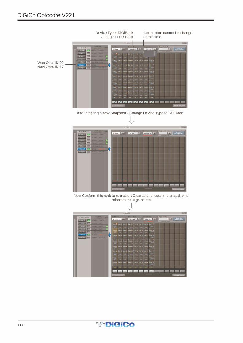
1) Ensure that the SD Series console is running Optocore Firmware V221 (See Technical Note 252)2) In SD software V370+, load the session and open the Snapshot panel.3) Make a snapshot (to save all routing, input gains and other rack parameters) and ensure that the Recall Scope can recall all of thisinformation.To do this both Global and Recall Scopes should have Input and Output channels and Input and Output Devices ticked for all relevantinput and output routes.4) Open the Setup/Audio IO panel on the Master screen5) Select the Opto ports (usually ports 5 and 6 which will be set as DiGiRacks) and set them to be SDRack, and set Optocore ID ifrequired.The Optocore IDs will have the following equivalents by default:DiGiRack ID30 = SD Rack ID17DiGiRack ID31 = SD Rack ID18DiGiRack ID32 = SD Rack ID19DiGiRack ID33 = SD Rack ID206) Manually (or automatically if connected) conform the racks to match the previous hardware setup.7) Recall the snapshot – this should reinstate all the routing lost when the DiGiRacks were converted to SD Racks8) Check sync is set to Optocore9) Ensure that the required rack output cards are assigned to your console Optocore ID number (2.1.2 Quick Start Guide)10) Save session as a New File
To run the console at 96KHz, two MADI Ports are required per 56 channel MADI streamTo convert the session to 96KHz (optional)1) Make sure that MADI Ports 1-4 are all defined as DiGiRacks2) Open Session structure and select 96K sample rate with appropriate mode eg 96 busses mode and Restructure3) When you open Audio IO, you should now see 2 MADI Ports.. 1 : MADI 1/2 & 2 : MADI 3/4 .Ports 5 and 6 should remain as the SD Racks (as set above)4) Save session as a New File
DiGiCo Optocore V221
A1-6
Device Type=DiGiRackChange to SD Rack
After creating a new Snapshot - Change Device Type to SD Rack
Now Conform this rack to recreate I/O cards and recall the snapshot toreinstate input gains etc
Connection cannot be changedat this time
Was Opto ID 30Now Opto ID 17
DiGiCo Optocore V221
A1-7
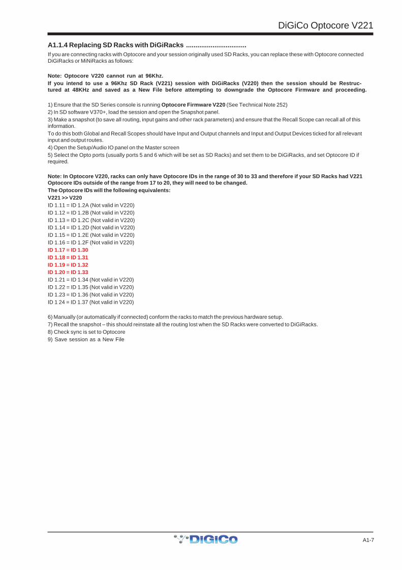
A1.1.4 Replacing SD Racks with DiGiRacks ................................If you are connecting racks with Optocore and your session originally used SD Racks, you can replace these with Optocore connectedDiGiRacks or MiNiRacks as follows:
Note: Optocore V220 cannot run at 96Khz.If you intend to use a 96Khz SD Rack (V221) session with DiGiRacks (V220) then the session should be Restruc-tured at 48KHz and saved as a New File before attempting to downgrade the Optocore Firmware and proceeding.
1) Ensure that the SD Series console is running Optocore Firmware V220 (See Technical Note 252)2) In SD software V370+, load the session and open the Snapshot panel.3) Make a snapshot (to save all routing, input gains and other rack parameters) and ensure that the Recall Scope can recall all of thisinformation.To do this both Global and Recall Scopes should have Input and Output channels and Input and Output Devices ticked for all relevantinput and output routes.4) Open the Setup/Audio IO panel on the Master screen5) Select the Opto ports (usually ports 5 and 6 which will be set as SD Racks) and set them to be DiGiRacks, and set Optocore ID ifrequired.
Note: In Optocore V220, racks can only have Optocore IDs in the range of 30 to 33 and therefore if your SD Racks had V221Optocore IDs outside of the range from 17 to 20, they will need to be changed.The Optocore IDs will the following equivalents:V221 >> V220ID 1.11 = ID 1.2A (Not valid in V220)ID 1.12 = ID 1.2B (Not valid in V220)ID 1.13 = ID 1.2C (Not valid in V220)ID 1.14 = ID 1.2D (Not valid in V220)ID 1.15 = ID 1.2E (Not valid in V220)ID 1.16 = ID 1.2F (Not valid in V220)ID 1.17 = ID 1.30ID 1.18 = ID 1.31ID 1.19 = ID 1.32ID 1.20 = ID 1.33ID 1.21 = ID 1.34 (Not valid in V220)ID 1.22 = ID 1.35 (Not valid in V220)ID 1.23 = ID 1.36 (Not valid in V220)ID 1 24 = ID 1.37 (Not valid in V220)
6) Manually (or automatically if connected) conform the racks to match the previous hardware setup.7) Recall the snapshot – this should reinstate all the routing lost when the SD Racks were converted to DiGiRacks.8) Check sync is set to Optocore9) Save session as a New File
DiGiCo Optocore V221
A1-8
A2.1 The Audio IO Panel
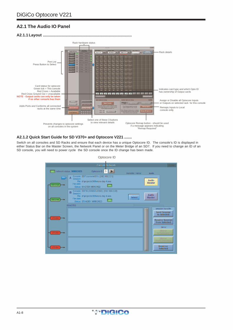
A2.1.1 Layout .................................................................................
Port ListPress Button to Select
Rack hardware status
Rack details
Adds Ports and Conforms all connected racks at the same time Remaps Inputs to Local
console onlly
Assign or Disable all Optocore Inputsor Outputs on selected rack for this console
Indicates card type and which Opto IDhas ownership of Output cards
Card status for optocoreGreen tick = This console
Red Cross = AvailableRed Cross Greyed Out = Unavailable
NOTE - Output cards can only be taken if no other console has them
Prevents changes to optocore settingson all consoles in the system
Select one of these 3 buttonsto view relevant details Optocore Remap button - should be used
if a message appears indicating “Remap Required”
A2.1.2 Quick Start Guide for SD V370+ and Optocore V221 .......Switch on all consoles and SD Racks and ensure that each device has a unique Optocore ID. The console’s ID is displayed ineither Status Bar on the Master Screen, the Network Panel or on the Meter Bridge of an SD7. If you need to change an ID of anSD console, you will need to power cycle the SD console once the ID change has been made.
Optocore ID
DiGiCo Optocore V221
A1-9
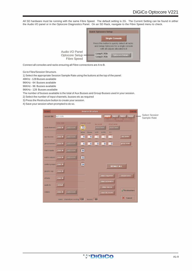
All SD hardware must be running with the same Fibre Speed. The default setting is 2G. The Current Setting can be found in eitherthe Audio I/O panel or in the Optocore Diagnostics Panel. On an SD Rack, navigate to the Fibre Speed menu to check.
Audio I/O PanelOptocore Setup
Fibre Speed
Connect all consoles and racks ensuring all Fibre connections are A to B.
Go to Files/Session Structure.1) Select the appropriate Session Sample Rate using the buttons at the top of the panel:48Khz - 128 Busses available96KHz - 64 Busses available96KHz - 96 Busses available96KHz - 128 Busses availableThe number of busses available is the total of Aux Busses and Group Busses used in your session.2) Select the number of input channels, busses etc as required3) Press the Restructure button to create your session.4) Save your session when prompted to do so.
Select SessionSample Rate
DiGiCo Optocore V221
A1-10
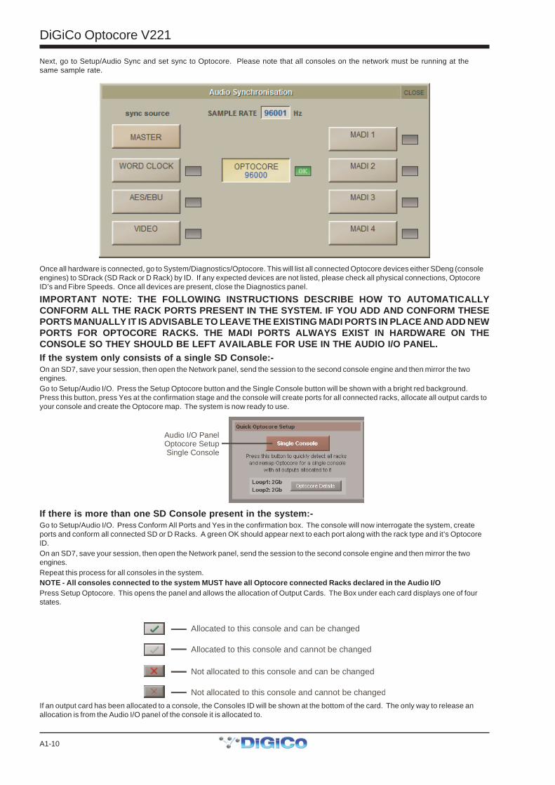
Next, go to Setup/Audio Sync and set sync to Optocore. Please note that all consoles on the network must be running at thesame sample rate.
Once all hardware is connected, go to System/Diagnostics/Optocore. This will list all connected Optocore devices either SDeng (consoleengines) to SDrack (SD Rack or D Rack) by ID. If any expected devices are not listed, please check all physical connections, OptocoreID’s and Fibre Speeds. Once all devices are present, close the Diagnostics panel.
IMPORTANT NOTE: THE FOLLOWING INSTRUCTIONS DESCRIBE HOW TO AUTOMATICALLYCONFORM ALL THE RACK PORTS PRESENT IN THE SYSTEM. IF YOU ADD AND CONFORM THESEPORTS MANUALLY IT IS ADVISABLE TO LEAVE THE EXISTING MADI PORTS IN PLACE AND ADD NEWPORTS FOR OPTOCORE RACKS. THE MADI PORTS ALWAYS EXIST IN HARDWARE ON THECONSOLE SO THEY SHOULD BE LEFT AVAILABLE FOR USE IN THE AUDIO I/O PANEL.If the system only consists of a single SD Console:-On an SD7, save your session, then open the Network panel, send the session to the second console engine and then mirror the twoengines.Go to Setup/Audio I/O. Press the Setup Optocore button and the Single Console button will be shown with a bright red background.Press this button, press Yes at the confirmation stage and the console will create ports for all connected racks, allocate all output cards toyour console and create the Optocore map. The system is now ready to use.
Audio I/O PanelOptocore SetupSingle Console
If there is more than one SD Console present in the system:-Go to Setup/Audio I/O. Press Conform All Ports and Yes in the confirmation box. The console will now interrogate the system, createports and conform all connected SD or D Racks. A green OK should appear next to each port along with the rack type and it’s OptocoreID.On an SD7, save your session, then open the Network panel, send the session to the second console engine and then mirror the twoengines.Repeat this process for all consoles in the system.NOTE - All consoles connected to the system MUST have all Optocore connected Racks declared in the Audio I/OPress Setup Optocore. This opens the panel and allows the allocation of Output Cards. The Box under each card displays one of fourstates.
Allocated to this console and can be changed
Not allocated to this console and can be changed
Allocated to this console and cannot be changed
Not allocated to this console and cannot be changed
If an output card has been allocated to a console, the Consoles ID will be shown at the bottom of the card. The only way to release anallocation is from the Audio I/O panel of the console it is allocated to.
DiGiCo Optocore V221
A1-11
NOTE: Changing card allocations with these buttons is only possible if the Optocore Setup button is pressed first
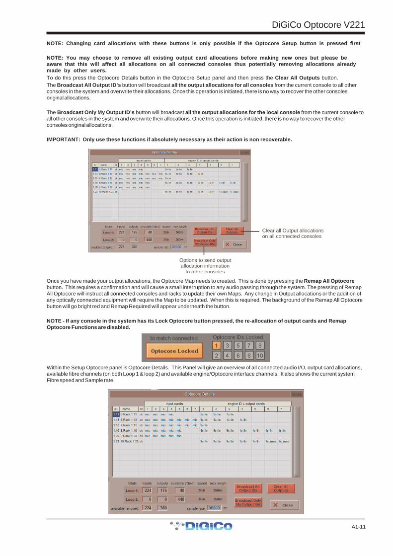
NOTE: You may choose to remove all existing output card allocations before making new ones but please beaware that this will affect all allocations on all connected consoles thus potentially removing allocations alreadymade by other users.To do this press the Optocore Details button in the Optocore Setup panel and then press the Clear All Outputs button.The Broadcast All Output ID’s button will broadcast all the output allocations for all consoles from the current console to all otherconsoles in the system and overwrite their allocations. Once this operation is initiated, there is no way to recover the other consolesoriginal allocations.
The Broadcast Only My Output ID’s button will broadcast all the output allocations for the local console from the current console toall other consoles in the system and overwrite their allocations. Once this operation is initiated, there is no way to recover the otherconsoles original allocations.
IMPORTANT: Only use these functions if absolutely necessary as their action is non recoverable.
Clear all Output allocationson all connected consoles
Options to send outputallocation information
to other consoles
Once you have made your output allocations, the Optocore Map needs to created. This is done by pressing the Remap All Optocorebutton. This requires a confirmation and will cause a small interruption to any audio passing through the system. The pressing of RemapAll Optocore will instruct all connected consoles and racks to update their own Maps. Any change in Output allocations or the addition ofany optically connected equipment will require the Map to be updated. When this is required, The background of the Remap All Optocorebutton will go bright red and Remap Required will appear underneath the button.
NOTE - If any console in the system has its Lock Optocore button pressed, the re-allocation of output cards and RemapOptocore Functions are disabled.
Within the Setup Optocore panel is Optocore Details. This Panel will give an overview of all connected audio I/O, output card allocations,available fibre channels (on both Loop 1 & loop 2) and available engine/Optocore interface channels. It also shows the current systemFibre speed and Sample rate.
DiGiCo Optocore V221
A1-12
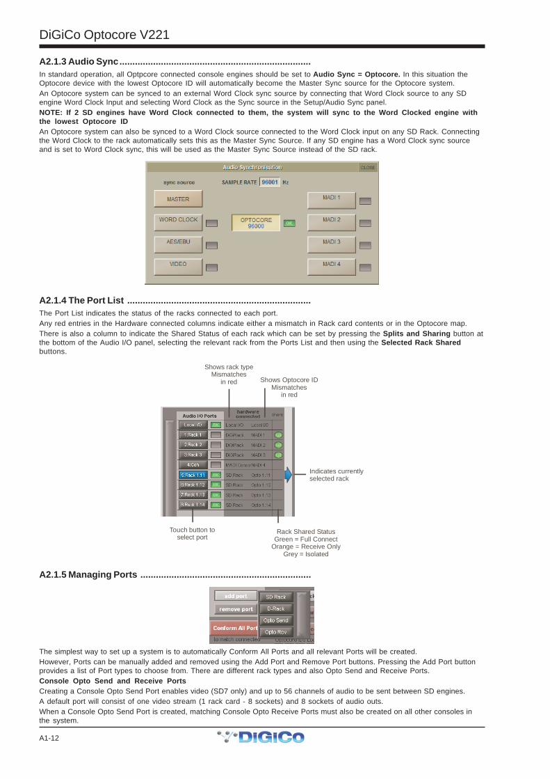
A2.1.3 Audio Sync..........................................................................In standard operation, all Optpcore connected console engines should be set to Audio Sync = Optocore. In this situation theOptocore device with the lowest Optocore ID will automatically become the Master Sync source for the Optocore system.An Optocore system can be synced to an external Word Clock sync source by connecting that Word Clock source to any SDengine Word Clock Input and selecting Word Clock as the Sync source in the Setup/Audio Sync panel.NOTE: If 2 SD engines have Word Clock connected to them, the system will sync to the Word Clocked engine withthe lowest Optocore IDAn Optocore system can also be synced to a Word Clock source connected to the Word Clock input on any SD Rack. Connectingthe Word Clock to the rack automatically sets this as the Master Sync Source. If any SD engine has a Word Clock sync sourceand is set to Word Clock sync, this will be used as the Master Sync Source instead of the SD rack.
A2.1.4 The Port List .......................................................................The Port List indicates the status of the racks connected to each port.Any red entries in the Hardware connected columns indicate either a mismatch in Rack card contents or in the Optocore map.There is also a column to indicate the Shared Status of each rack which can be set by pressing the Splits and Sharing button atthe bottom of the Audio I/O panel, selecting the relevant rack from the Ports List and then using the Selected Rack Sharedbuttons.
Shows rack typeMismatches
in red Shows Optocore IDMismatches
in red
Rack Shared StatusGreen = Full Connect
Orange = Receive OnlyGrey = Isolated
Touch button to select port
Indicates currentlyselected rack
A2.1.5 Managing Ports ..................................................................
The simplest way to set up a system is to automatically Conform All Ports and all relevant Ports will be created.However, Ports can be manually added and removed using the Add Port and Remove Port buttons. Pressing the Add Port buttonprovides a list of Port types to choose from. There are different rack types and also Opto Send and Receive Ports.Console Opto Send and Receive PortsCreating a Console Opto Send Port enables video (SD7 only) and up to 56 channels of audio to be sent between SD engines.A default port will consist of one video stream (1 rack card - 8 sockets) and 8 sockets of audio outs.When a Console Opto Send Port is created, matching Console Opto Receive Ports must also be created on all other consoles inthe system.
DiGiCo Optocore V221
A1-13
The simplest way to create the Console Opto Receive Ports is to press the Conform All Ports button on all the other consoles andthis will automatically create the relevant Receive Ports,IMPORTANT: When these Ports are added an Optocore Remap is required and this will only work correctly if all theconsoles in the system have matching Send and Receive Ports.
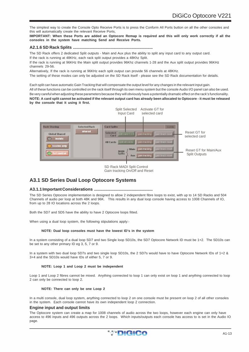
A2.1.6 SD Rack Splits ....................................................................The SD Rack offers 2 dedicated Split outputs - Main and Aux plus the ability to split any input card to any output card.If the rack is running at 48KHz, each rack split output provides a 48Khz Split.If the rack is running at 96KHz the Main split output provides 96Khz channels 1-28 and the Aux split output provides 96KHzchannels 29-56.Alternatively, If the rack is running at 96KHz each split output can provide 56 channels at 48KHz.The setting of these modes can only be adjusted on the SD Rack itself - please see the SD Rack documentation for details.
Each split can have automatic Gain Tracking that will compensate the output level for any changes in the relevant input gain.All of these functions can be controlled on the rack itself through its own menu system but the console Audio I/O panel can also be used.Be very careful when adjusting these parameters because they will obviously have a potentially dramatic effect on the rack’s functionality.NOTE: A card split cannot be activated if the relevant output card has already been allocated to Optocore - it must be releasedby the console that it using it first.
Split SelectedInput Card
Activate GT for selected card
Reset GT for selected card
Reset GT for Main/Aux Split Outputs
SD Rack MADI Split ControlGain tracking On/Off and Reset
A3.1 SD Series Dual Loop Optocore Systems
A3.1.1 Important Considerations ..................................................The SD Series Optocore implementation is designed to allow 2 independent fibre loops to exist, with up to 14 SD Racks and 504Channels of audio per loop at both 48K and 96K. This results in any dual loop console having access to 1008 Channels of IO,from up to 28 IO locations across the 2 loops.
Both the SD7 and SD5 have the ability to have 2 Optocore loops fitted.
When using a dual loop system, the following stipulations apply:-
NOTE: Dual loop consoles must have the lowest ID’s in the system
In a system consisting of a dual loop SD7 and two Single loop SD10s, the SD7 Optocore Network ID must be 1+2. The SD10s canbe set to any other primary ID eg 3, 5, 7 or 9.
In a system with two dual loop SD7s and two single loop SD10s, the 2 SD7s would have to have Optocore Network IDs of 1+2 &3+4 and the SD10s would have IDs of either 5, 7 or 9.
NOTE: Loop 1 and Loop 2 must be independent
Loop 1 and Loop 2 fibres cannot be mixed. Anything connected to loop 1 can only exist on loop 1 and anything connected to loop2 can only be connected to loop 2.
NOTE: There can only be one Loop 2
In a multi console, dual loop system, anything connected to loop 2 on one console must be present on loop 2 of all other consolesin the system. Each console cannot have its own independent loop 2 connection.
Engine input and output limitsThe Optocore system can create a map for 1008 channels of audio across the two loops, however each engine can only haveaccess to 496 inputs and 496 outputs across the 2 loops. Which inputs/outputs each console has access to is set in the Audio IOpage.
DiGiCo Optocore V221
A1-14
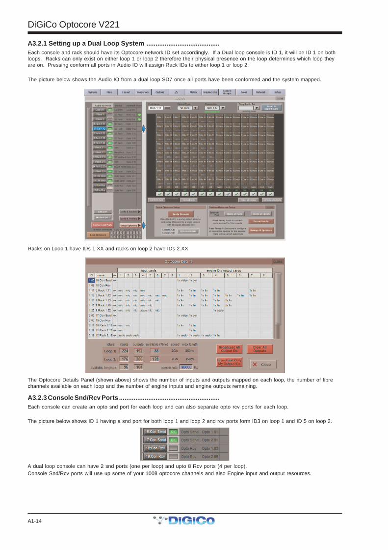
A3.2.1 Setting up a Dual Loop System ........................................Each console and rack should have its Optocore network ID set accordingly. If a Dual loop console is ID 1, it will be ID 1 on bothloops. Racks can only exist on either loop 1 or loop 2 therefore their physical presence on the loop determines which loop theyare on. Pressing conform all ports in Audio IO will assign Rack IDs to either loop 1 or loop 2.
The picture below shows the Audio IO from a dual loop SD7 once all ports have been conformed and the system mapped.
Racks on Loop 1 have IDs 1.XX and racks on loop 2 have IDs 2.XX
The Optocore Details Panel (shown above) shows the number of inputs and outputs mapped on each loop, the number of fibrechannels available on each loop and the number of engine inputs and engine outputs remaining.
A3.2.3 Console Snd/Rcv Ports .......................................................Each console can create an opto snd port for each loop and can also separate opto rcv ports for each loop.
The picture below shows ID 1 having a snd port for both loop 1 and loop 2 and rcv ports form ID3 on loop 1 and ID 5 on loop 2.
A dual loop console can have 2 snd ports (one per loop) and upto 8 Rcv ports (4 per loop).Console Snd/Rcv ports will use up some of your 1008 optocore channels and also Engine input and output resources.

DiGiCo Optocore V221
A1-15
A3.2.4 Single Loop Console on Loop 2 ........................................SD8, SD9, SD10 and SD11 consoles are only able to have connections fitted one loop and the internal connections within theconsole will be to loop 1.
In the Options>Console menu, the Enable Optocore option allows the console to either be a loop 1 console or loop 2 console(shown below) without having to alter the internal connections.
Single loop consoles operate independently on each loop. For example, a system can exist of a dual loop SD7 (IDs 1+2), an SD8(ID3) on loop 1 and an SD10 (also ID3) on loop 2.
SD5s & SD7s that only have a single loop fitted can also set to operate on either Loop 1 or Loop 2.