Embed Size (px)
Citation preview
Residential Compliance Forms April 2005
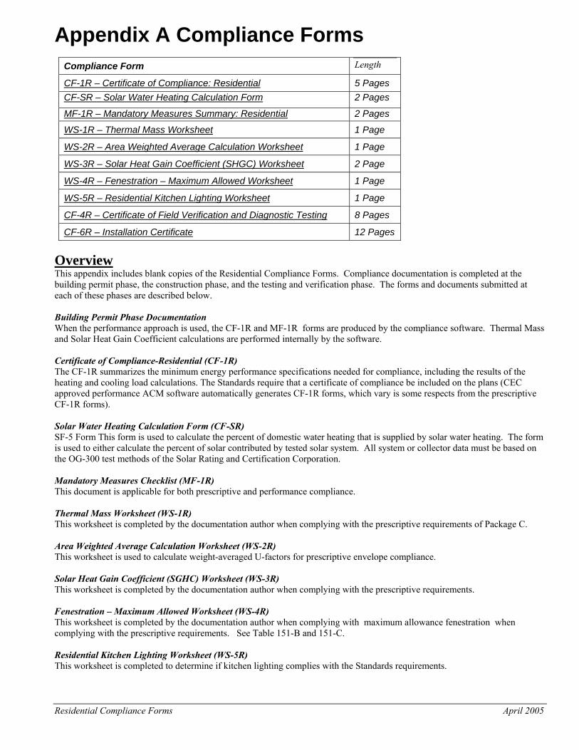
Appendix A Compliance Forms
Compliance Form Length
CF-1R – Certificate of Compliance: Residential 5 Pages CF-SR – Solar Water Heating Calculation Form 2 Pages
MF-1R – Mandatory Measures Summary: Residential 2 Pages
WS-1R – Thermal Mass Worksheet 1 Page
WS-2R – Area Weighted Average Calculation Worksheet 1 Page
WS-3R – Solar Heat Gain Coefficient (SHGC) Worksheet 2 Page
WS-4R – Fenestration – Maximum Allowed Worksheet 1 Page
WS-5R – Residential Kitchen Lighting Worksheet 1 Page
CF-4R – Certificate of Field Verification and Diagnostic Testing 8 Pages
CF-6R – Installation Certificate 12 Pages Overview This appendix includes blank copies of the Residential Compliance Forms. Compliance documentation is completed at the building permit phase, the construction phase, and the testing and verification phase. The forms and documents submitted at each of these phases are described below. Building Permit Phase Documentation When the performance approach is used, the CF-1R and MF-1R forms are produced by the compliance software. Thermal Mass and Solar Heat Gain Coefficient calculations are performed internally by the software. Certificate of Compliance-Residential (CF-1R) The CF-1R summarizes the minimum energy performance specifications needed for compliance, including the results of the heating and cooling load calculations. The Standards require that a certificate of compliance be included on the plans (CEC approved performance ACM software automatically generates CF-1R forms, which vary is some respects from the prescriptive CF-1R forms). Solar Water Heating Calculation Form (CF-SR) SF-5 Form This form is used to calculate the percent of domestic water heating that is supplied by solar water heating. The form is used to either calculate the percent of solar contributed by tested solar system. All system or collector data must be based on the OG-300 test methods of the Solar Rating and Certification Corporation. Mandatory Measures Checklist (MF-1R) This document is applicable for both prescriptive and performance compliance. Thermal Mass Worksheet (WS-1R) This worksheet is completed by the documentation author when complying with the prescriptive requirements of Package C. Area Weighted Average Calculation Worksheet (WS-2R) This worksheet is used to calculate weight-averaged U-factors for prescriptive envelope compliance. Solar Heat Gain Coefficient (SGHC) Worksheet (WS-3R) This worksheet is completed by the documentation author when complying with the prescriptive requirements. Fenestration – Maximum Allowed Worksheet (WS-4R) This worksheet is completed by the documentation author when complying with maximum allowance fenestration when complying with the prescriptive requirements. See Table 151-B and 151-C. Residential Kitchen Lighting Worksheet (WS-5R) This worksheet is completed to determine if kitchen lighting complies with the Standards requirements.
Residential Compliance Forms April 2005
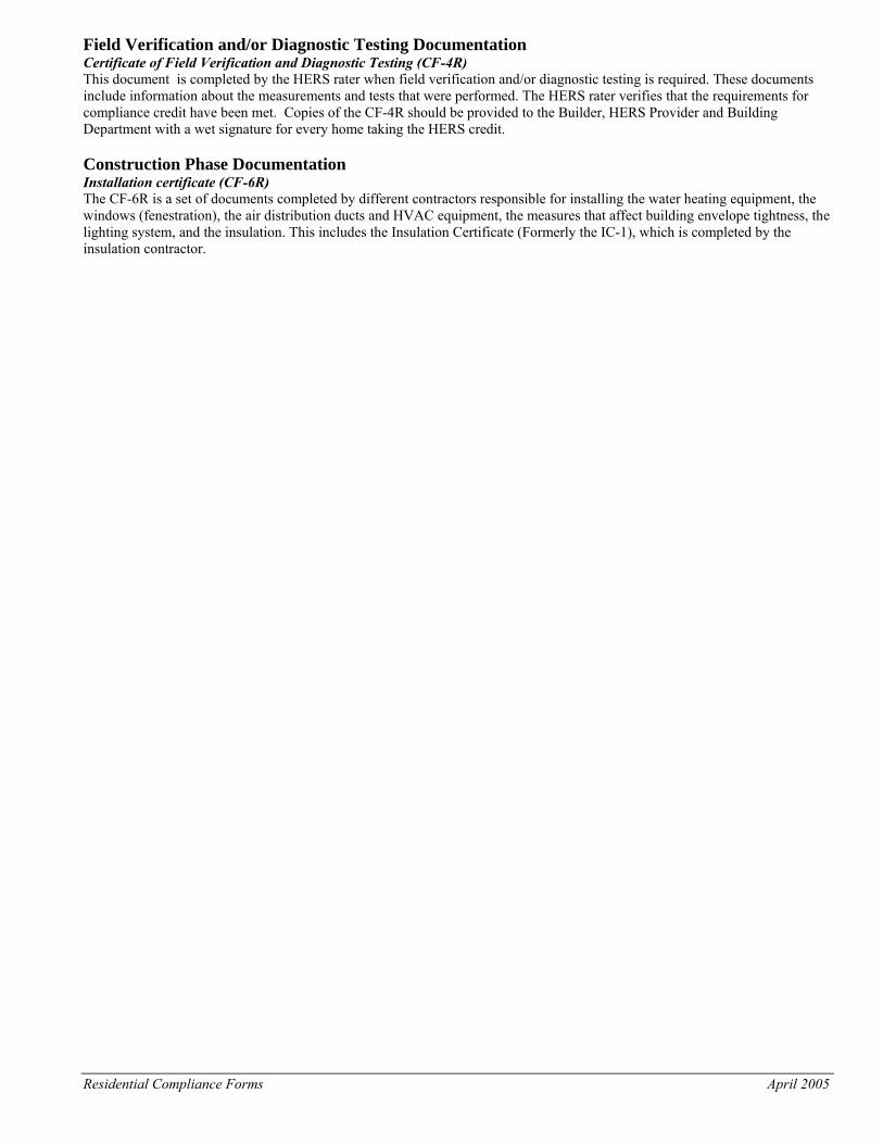
Field Verification and/or Diagnostic Testing Documentation Certificate of Field Verification and Diagnostic Testing (CF-4R) This document is completed by the HERS rater when field verification and/or diagnostic testing is required. These documents include information about the measurements and tests that were performed. The HERS rater verifies that the requirements for compliance credit have been met. Copies of the CF-4R should be provided to the Builder, HERS Provider and Building Department with a wet signature for every home taking the HERS credit. Construction Phase Documentation Installation certificate (CF-6R) The CF-6R is a set of documents completed by different contractors responsible for installing the water heating equipment, the windows (fenestration), the air distribution ducts and HVAC equipment, the measures that affect building envelope tightness, the lighting system, and the insulation. This includes the Insulation Certificate (Formerly the IC-1), which is completed by the insulation contractor.
Residential Compliance Forms December 2005
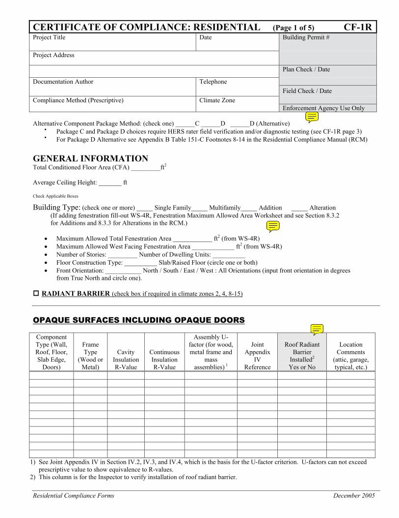
CERTIFICATE OF COMPLIANCE: RESIDENTIAL (Page 1 of 5) CF-1RProject Title Date Building Permit #
Project Address
Plan Check / Date
Documentation Author Telephone
Field Check / Date
Compliance Method (Prescriptive) Climate Zone
Enforcement Agency Use Only
Alternative Component Package Method: (check one) ______C ______D ______D (Alternative)
• Package C and Package D choices require HERS rater field verification and/or diagnostic testing (see CF-1R page 3)
• For Package D Alternative see Appendix B Table 151-C Footnotes 8-14 in the Residential Compliance Manual (RCM)
GENERAL INFORMATION Total Conditioned Floor Area (CFA) _________ft2 Average Ceiling Height: _______ ft
Check Applicable Boxes Building Type: (check one or more) _____ Single Family_____ Multifamily_____ Addition _____ Alteration
(If adding fenestration fill-out WS-4R, Fenestration Maximum Allowed Area Worksheet and see Section 8.3.2 for Additions and 8.3.3 for Alterations in the RCM.)
• Maximum Allowed Total Fenestration Area ____________ ft2 (from WS-4R) • Maximum Allowed West Facing Fenestration Area _____________ ft2 (from WS-4R) • Number of Stories: _________ Number of Dwelling Units: __________ • Floor Construction Type: __________ Slab/Raised Floor (circle one or both) • Front Orientation: ___________ North / South / East / West : All Orientations (input front orientation in degrees
from True North and circle one).
RADIANT BARRIER (check box if required in climate zones 2, 4, 8-15)
OPAQUE SURFACES INCLUDING OPAQUE DOORS
Component Type (Wall, Roof, Floor, Slab Edge,
Doors)
Frame Type
(Wood or Metal)
Cavity Insulation R-Value
Continuous Insulation R-Value
Assembly U-factor (for wood, metal frame and
mass assemblies) 1
Joint Appendix
IV Reference
Roof Radiant Barrier
Installed2 Yes or No
Location Comments
(attic, garage, typical, etc.)
1) See Joint Appendix IV in Section IV.2, IV.3, and IV.4, which is the basis for the U-factor criterion. U-factors can not exceed prescriptive value to show equivalence to R-values.
2) This column is for the Inspector to verify installation of roof radiant barrier.
Residential Compliance Forms December 2005
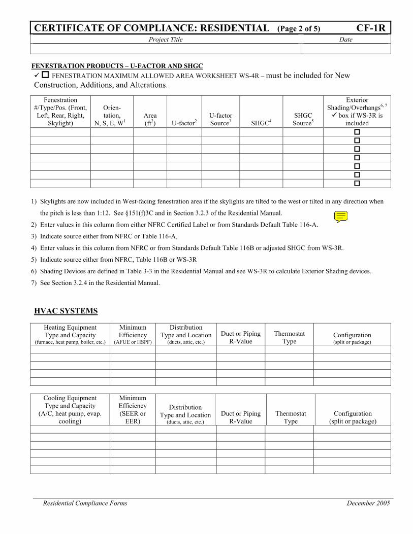
CERTIFICATE OF COMPLIANCE: RESIDENTIAL (Page 2 of 5) CF-1RProject Title Date
FENESTRATION PRODUCTS – U-FACTOR AND SHGC FENESTRATION MAXIMUM ALLOWED AREA WORKSHEET WS-4R – must be included for New
Construction, Additions, and Alterations.
Fenestration #/Type/Pos. (Front, Left, Rear, Right,
Skylight)
Orien- tation,
N, S, E, W1 Area (ft2) U-factor2
U-factor Source3 SHGC4
SHGC Source5
Exterior Shading/Overhangs6, 7
box if WS-3R is included
1) Skylights are now included in West-facing fenestration area if the skylights are tilted to the west or tilted in any direction when
the pitch is less than 1:12. See §151(f)3C and in Section 3.2.3 of the Residential Manual.
2) Enter values in this column from either NFRC Certified Label or from Standards Default Table 116-A.
3) Indicate source either from NFRC or Table 116-A,
4) Enter values in this column from NFRC or from Standards Default Table 116B or adjusted SHGC from WS-3R.
5) Indicate source either from NFRC, Table 116B or WS-3R
6) Shading Devices are defined in Table 3-3 in the Residential Manual and see WS-3R to calculate Exterior Shading devices.
7) See Section 3.2.4 in the Residential Manual.
HVAC SYSTEMS
Heating Equipment Type and Capacity
(furnace, heat pump, boiler, etc.)
Minimum Efficiency
(AFUE or HSPF)
Distribution Type and Location
(ducts, attic, etc.) Duct or Piping
R-Value Thermostat
Type Configuration (split or package)
Cooling Equipment Type and Capacity
(A/C, heat pump, evap. cooling)
Minimum Efficiency (SEER or
EER)
Distribution Type and Location
(ducts, attic, etc.) Duct or Piping
R-Value Thermostat
Type Configuration
(split or package)
Residential Compliance Forms December 2005
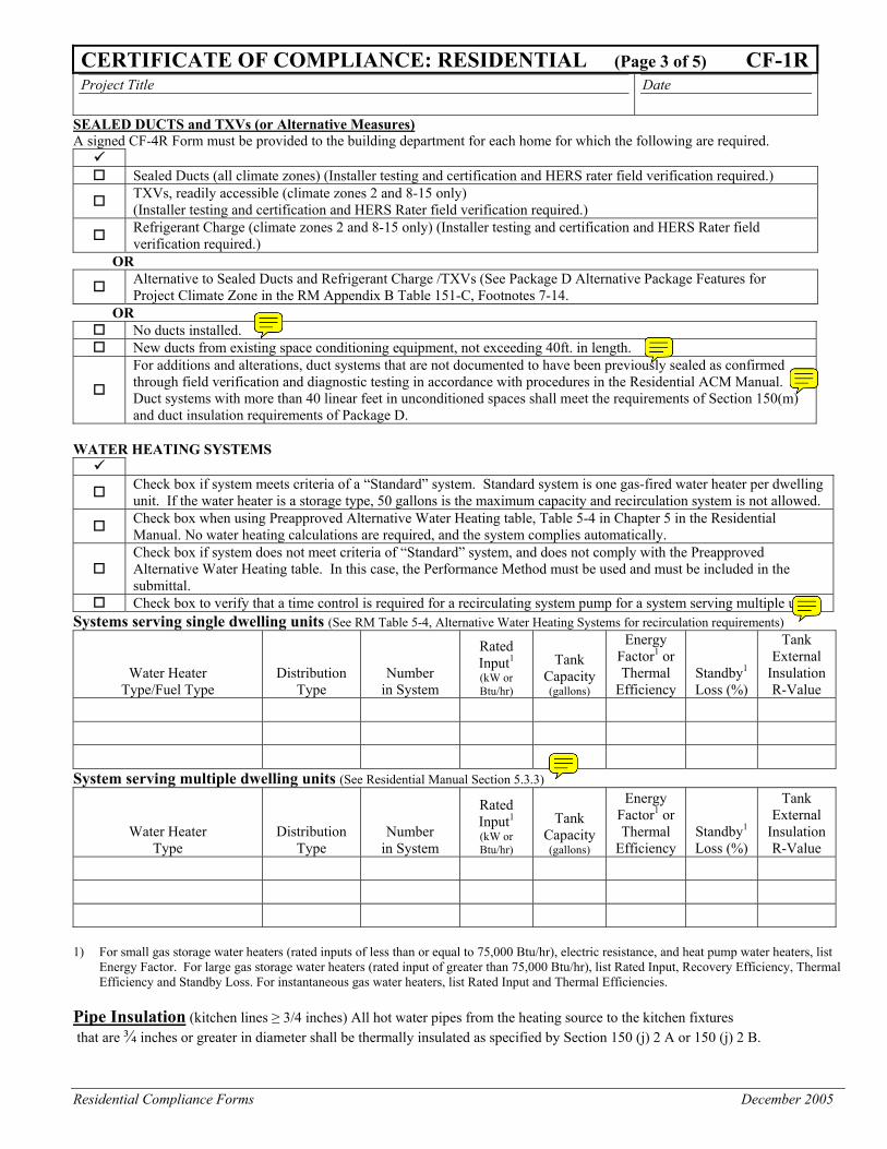
CERTIFICATE OF COMPLIANCE: RESIDENTIAL (Page 3 of 5) CF-1RProject Title Date
SEALED DUCTS and TXVs (or Alternative Measures) A signed CF-4R Form must be provided to the building department for each home for which the following are required.
Sealed Ducts (all climate zones) (Installer testing and certification and HERS rater field verification required.)
TXVs, readily accessible (climate zones 2 and 8-15 only) (Installer testing and certification and HERS Rater field verification required.)
Refrigerant Charge (climate zones 2 and 8-15 only) (Installer testing and certification and HERS Rater field verification required.)
OR
Alternative to Sealed Ducts and Refrigerant Charge /TXVs (See Package D Alternative Package Features for Project Climate Zone in the RM Appendix B Table 151-C, Footnotes 7-14.
OR No ducts installed. New ducts from existing space conditioning equipment, not exceeding 40ft. in length.
For additions and alterations, duct systems that are not documented to have been previously sealed as confirmed through field verification and diagnostic testing in accordance with procedures in the Residential ACM Manual. Duct systems with more than 40 linear feet in unconditioned spaces shall meet the requirements of Section 150(m) and duct insulation requirements of Package D.
WATER HEATING SYSTEMS
Check box if system meets criteria of a “Standard” system. Standard system is one gas-fired water heater per dwelling unit. If the water heater is a storage type, 50 gallons is the maximum capacity and recirculation system is not allowed.
Check box when using Preapproved Alternative Water Heating table, Table 5-4 in Chapter 5 in the Residential Manual. No water heating calculations are required, and the system complies automatically.
Check box if system does not meet criteria of “Standard” system, and does not comply with the Preapproved Alternative Water Heating table. In this case, the Performance Method must be used and must be included in the submittal.
Check box to verify that a time control is required for a recirculating system pump for a system serving multiple units Systems serving single dwelling units (See RM Table 5-4, Alternative Water Heating Systems for recirculation requirements)
Water Heater Type/Fuel Type
Distribution Type
Number
in System
Rated Input1
(kW or Btu/hr)
Tank Capacity (gallons)
Energy Factor1 or Thermal
Efficiency Standby1 Loss (%)
Tank External
Insulation R-Value
System serving multiple dwelling units (See Residential Manual Section 5.3.3)
Water Heater Type
Distribution Type
Number
in System
Rated Input1
(kW or Btu/hr)
Tank Capacity (gallons)
Energy Factor1 or Thermal
Efficiency Standby1 Loss (%)
Tank External
Insulation R-Value
1) For small gas storage water heaters (rated inputs of less than or equal to 75,000 Btu/hr), electric resistance, and heat pump water heaters, list
Energy Factor. For large gas storage water heaters (rated input of greater than 75,000 Btu/hr), list Rated Input, Recovery Efficiency, Thermal Efficiency and Standby Loss. For instantaneous gas water heaters, list Rated Input and Thermal Efficiencies.
Pipe Insulation (kitchen lines ≥ 3/4 inches) All hot water pipes from the heating source to the kitchen fixtures that are ¾ inches or greater in diameter shall be thermally insulated as specified by Section 150 (j) 2 A or 150 (j) 2 B.
Residential Compliance Forms December 2005
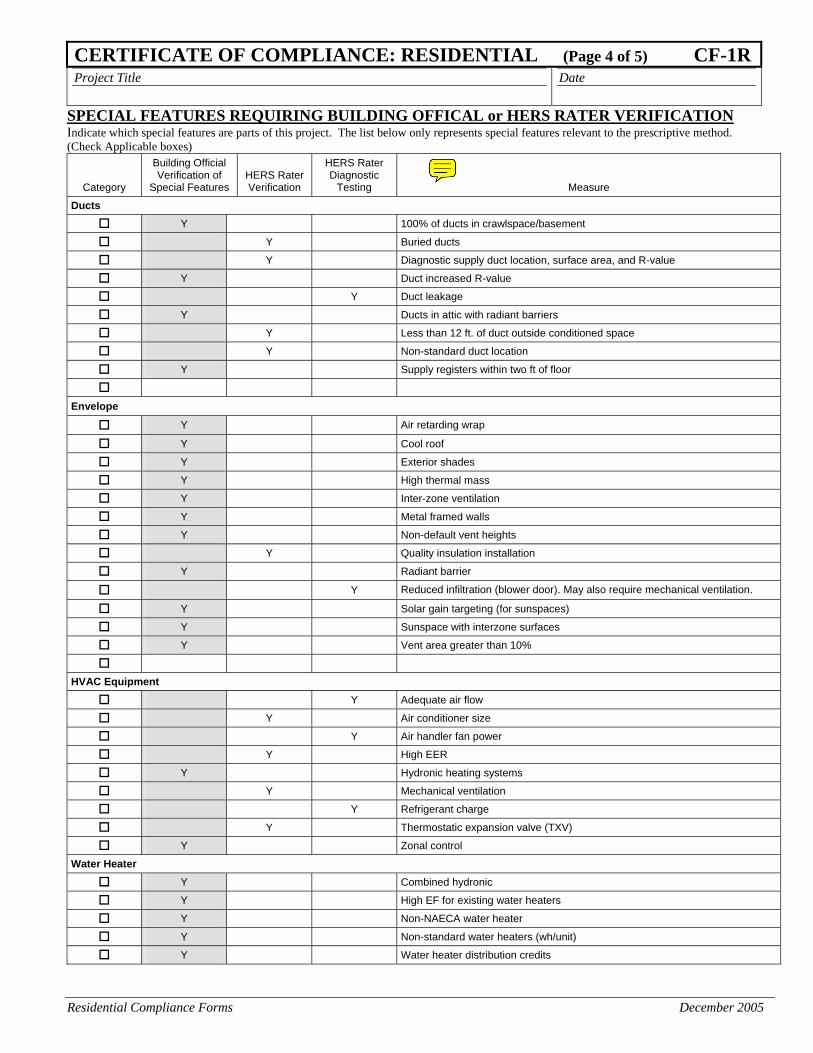
CERTIFICATE OF COMPLIANCE: RESIDENTIAL (Page 4 of 5) CF-1RProject Title Date
SPECIAL FEATURES REQUIRING BUILDING OFFICAL or HERS RATER VERIFICATION Indicate which special features are parts of this project. The list below only represents special features relevant to the prescriptive method. (Check Applicable boxes)
Category
Building Official Verification of
Special Features HERS Rater Verification
HERS Rater Diagnostic
Testing Measure
Ducts
Y 100% of ducts in crawlspace/basement
Y Buried ducts
Y Diagnostic supply duct location, surface area, and R-value
Y Duct increased R-value
Y Duct leakage
Y Ducts in attic with radiant barriers
Y Less than 12 ft. of duct outside conditioned space
Y Non-standard duct location
Y Supply registers within two ft of floor
Envelope
Y Air retarding wrap
Y Cool roof
Y Exterior shades
Y High thermal mass
Y Inter-zone ventilation
Y Metal framed walls
Y Non-default vent heights
Y Quality insulation installation
Y Radiant barrier
Y Reduced infiltration (blower door). May also require mechanical ventilation.
Y Solar gain targeting (for sunspaces)
Y Sunspace with interzone surfaces
Y Vent area greater than 10%
HVAC Equipment
Y Adequate air flow
Y Air conditioner size
Y Air handler fan power
Y High EER
Y Hydronic heating systems
Y Mechanical ventilation
Y Refrigerant charge
Y Thermostatic expansion valve (TXV)
Y Zonal control
Water Heater
Y Combined hydronic
Y High EF for existing water heaters
Y Non-NAECA water heater
Y Non-standard water heaters (wh/unit)
Y Water heater distribution credits
Residential Compliance Forms December 2005
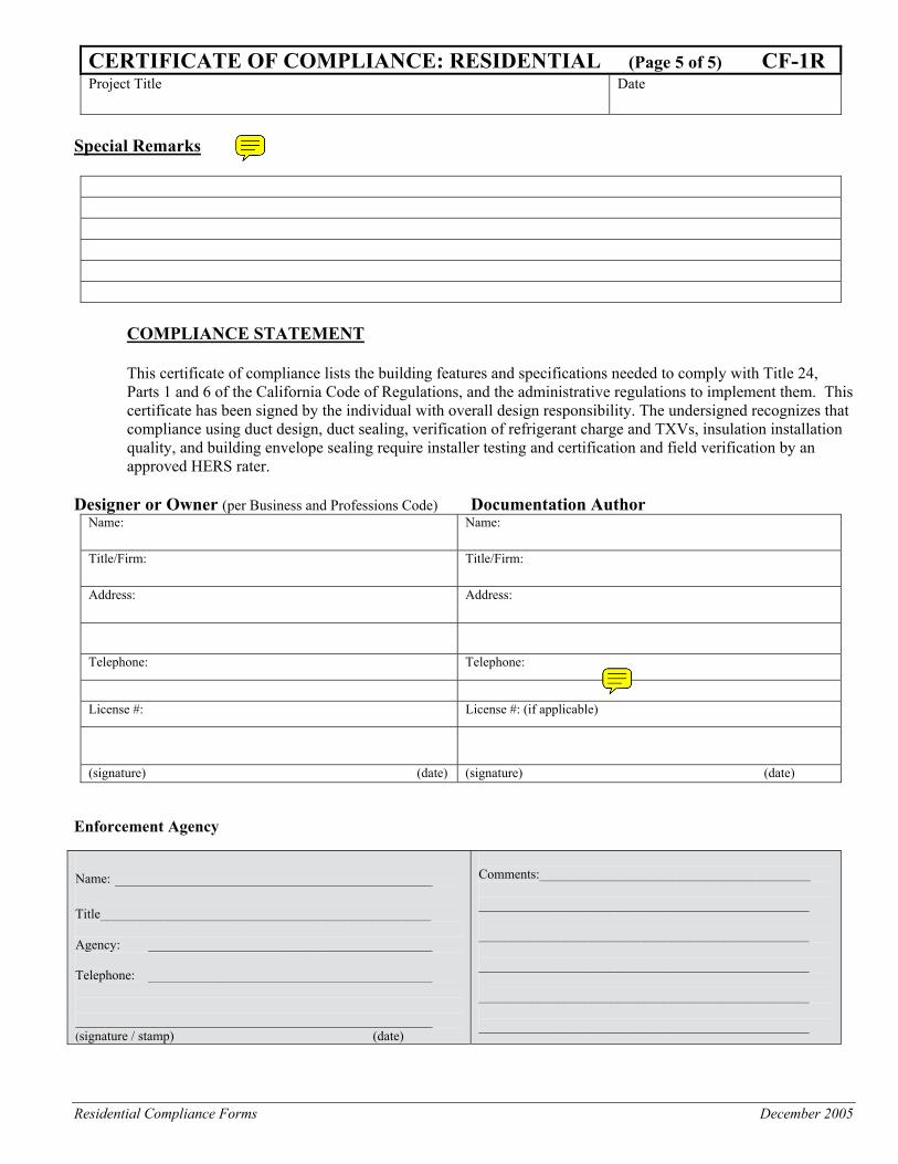
CERTIFICATE OF COMPLIANCE: RESIDENTIAL (Page 5 of 5) CF-1R Project Title Date
Special Remarks
COMPLIANCE STATEMENT This certificate of compliance lists the building features and specifications needed to comply with Title 24, Parts 1 and 6 of the California Code of Regulations, and the administrative regulations to implement them. This certificate has been signed by the individual with overall design responsibility. The undersigned recognizes that compliance using duct design, duct sealing, verification of refrigerant charge and TXVs, insulation installation quality, and building envelope sealing require installer testing and certification and field verification by an approved HERS rater.
Designer or Owner (per Business and Professions Code) Documentation Author
Name: Name: Title/Firm: Title/Firm: Address: Address: Telephone: Telephone:
License #: License #: (if applicable)
(signature) (date) (signature) (date)
Enforcement Agency Name: ____________________________________ Title__________________________________________________ Agency: ___________________________________________ Telephone: ___________________________________________ ______________________________________________________ (signature / stamp) (date)
Comments:_________________________________________ __________________________________________________ __________________________________________________ __________________________________________________ __________________________________________________ __________________________________________________
Residential Compliance Forms December 2005
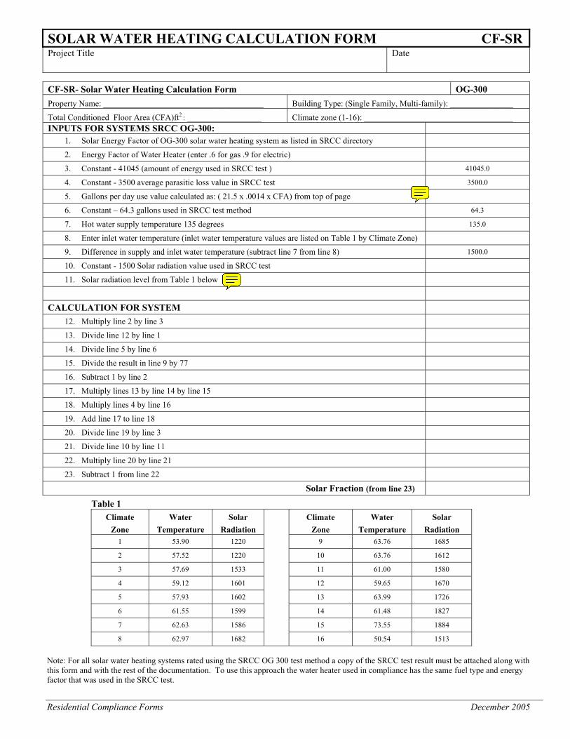
SOLAR WATER HEATING CALCULATION FORM CF-SRProject Title Date
CF-SR- Solar Water Heating Calculation Form OG-300 Property Name: ___________________________________________ Building Type: (Single Family, Multi-family): _________________
Total Conditioned Floor Area (CFA)ft2 : ____________________ Climate zone (1-16): ________________________________________ INPUTS FOR SYSTEMS SRCC OG-300:
1. Solar Energy Factor of OG-300 solar water heating system as listed in SRCC directory
2. Energy Factor of Water Heater (enter .6 for gas .9 for electric)
3. Constant - 41045 (amount of energy used in SRCC test ) 41045.0
4. Constant - 3500 average parasitic loss value in SRCC test 3500.0
5. Gallons per day use value calculated as: ( 21.5 x .0014 x CFA) from top of page
6. Constant – 64.3 gallons used in SRCC test method 64.3
7. Hot water supply temperature 135 degrees 135.0
8. Enter inlet water temperature (inlet water temperature values are listed on Table 1 by Climate Zone)
9. Difference in supply and inlet water temperature (subtract line 7 from line 8) 1500.0
10. Constant - 1500 Solar radiation value used in SRCC test
11. Solar radiation level from Table 1 below
CALCULATION FOR SYSTEM
12. Multiply line 2 by line 3
13. Divide line 12 by line 1
14. Divide line 5 by line 6
15. Divide the result in line 9 by 77
16. Subtract 1 by line 2
17. Multiply lines 13 by line 14 by line 15
18. Multiply lines 4 by line 16
19. Add line 17 to line 18
20. Divide line 19 by line 3
21. Divide line 10 by line 11
22. Multiply line 20 by line 21
23. Subtract 1 from line 22
Solar Fraction (from line 23)
Table 1 Climate
Zone Water
Temperature Solar
Radiation
Climate Zone
Water Temperature
Solar Radiation
1 53.90 1220 9 63.76 1685
2 57.52 1220 10 63.76 1612
3 57.69 1533 11 61.00 1580
4 59.12 1601 12 59.65 1670
5 57.93 1602 13 63.99 1726
6 61.55 1599 14 61.48 1827
7 62.63 1586 15 73.55 1884
8 62.97 1682 16 50.54 1513
Note: For all solar water heating systems rated using the SRCC OG 300 test method a copy of the SRCC test result must be attached along with this form and with the rest of the documentation. To use this approach the water heater used in compliance has the same fuel type and energy factor that was used in the SRCC test.
Residential Compliance Forms December 2005
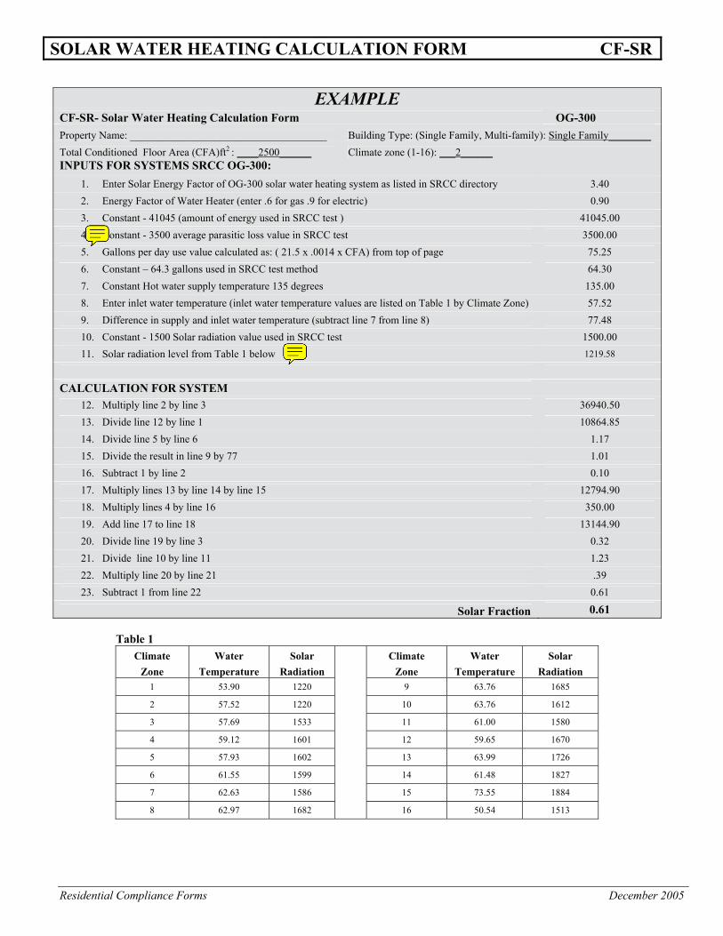
SOLAR WATER HEATING CALCULATION FORM CF-SR
EXAMPLE CF-SR- Solar Water Heating Calculation Form OG-300 Property Name: _____________________________________ Building Type: (Single Family, Multi-family): Single Family________ Total Conditioned Floor Area (CFA)ft2 : ____2500______ Climate zone (1-16): ___2______ INPUTS FOR SYSTEMS SRCC OG-300:
1. Enter Solar Energy Factor of OG-300 solar water heating system as listed in SRCC directory 3.40 2. Energy Factor of Water Heater (enter .6 for gas .9 for electric) 0.90 3. Constant - 41045 (amount of energy used in SRCC test ) 41045.00 4. Constant - 3500 average parasitic loss value in SRCC test 3500.00 5. Gallons per day use value calculated as: ( 21.5 x .0014 x CFA) from top of page 75.25 6. Constant – 64.3 gallons used in SRCC test method 64.30 7. Constant Hot water supply temperature 135 degrees 135.00 8. Enter inlet water temperature (inlet water temperature values are listed on Table 1 by Climate Zone) 57.52 9. Difference in supply and inlet water temperature (subtract line 7 from line 8) 77.48 10. Constant - 1500 Solar radiation value used in SRCC test 1500.00 11. Solar radiation level from Table 1 below 1219.58
CALCULATION FOR SYSTEM
12. Multiply line 2 by line 3 36940.50 13. Divide line 12 by line 1 10864.85 14. Divide line 5 by line 6 1.17 15. Divide the result in line 9 by 77 1.01 16. Subtract 1 by line 2 0.10 17. Multiply lines 13 by line 14 by line 15 12794.90 18. Multiply lines 4 by line 16 350.00 19. Add line 17 to line 18 13144.90 20. Divide line 19 by line 3 0.32 21. Divide line 10 by line 11 1.23 22. Multiply line 20 by line 21 .39 23. Subtract 1 from line 22 0.61
Solar Fraction 0.61 Table 1
Climate Zone
Water Temperature
Solar Radiation
Climate
Zone Water
Temperature Solar
Radiation 1 53.90 1220 9 63.76 1685
2 57.52 1220 10 63.76 1612
3 57.69 1533 11 61.00 1580
4 59.12 1601 12 59.65 1670
5 57.93 1602 13 63.99 1726
6 61.55 1599 14 61.48 1827
7 62.63 1586 15 73.55 1884
8 62.97 1682 16 50.54 1513
Residential Compliance Forms December 2005
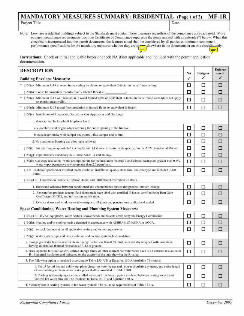
MANDATORY MEASURES SUMMARY: RESIDENTIAL (Page 1 of 2) MF-1RProject Title Date
Note: Low-rise residential buildings subject to the Standards must contain these measures regardless of the compliance approach used. More
stringent compliance requirements from the Certificate of Compliance supersede the items marked with an asterisk (*) below. When this checklist is incorporated into the permit documents, the features noted shall be considered by all parties as minimum component performance specifications for the mandatory measures whether they are shown elsewhere in the documents or on this checklist only.
Instructions: Check or initial applicable boxes or check NA if not applicable and included with the permit application documentation.
DESCRIPTION NA Designer
Enforce-ment
Building Envelope Measures:
* §150(a): Minimum R-19 in wood frame ceiling insulation or equivalent U-factor in metal frame ceiling. §150(b): Loose fill insulation manufacturer’s labeled R-Value: _____________. * §150(c): Minimum R-13 wall insulation in wood framed walls or equivalent U-factor in metal frame walls (does not apply
to exterior mass walls). * §150(d): Minimum R-13 raised floor insulation in framed floors or equivalent U-factor. §150(e): Installation of Fireplaces, Decorative Gas Appliances and Gas Logs. 1. Masonry and factory-built fireplaces have:
a. closeable metal or glass door covering the entire opening of the firebox b. outside air intake with damper and control, flue damper and control
2. No continuous burning gas pilot lights allowed. §150(f): Air retarding wrap installed to comply with §151 meets requirements specified in the ACM Residential Manual. §150(g): Vapor barriers mandatory in Climate Zones 14 and 16 only. §150(l): Slab edge insulation - water absorption rate for the insulation material alone without facings no greater than 0.3%,
water vapor permeance rate no greater than 2.0 perm/inch.
§118: Insulation specified or installed meets insulation installation quality standards. Indicate type and include CF-6R Form: _____________________
§116-§117: Fenestration Products, Exterior Doors, and Infiltration/Exfiltration Controls. 1. Doors and windows between conditioned and unconditioned spaces designed to limit air leakage.
2. Fenestration products (except field-fabricated) have label with certified U-factor, certified Solar Heat Gain Coefficient (SHGC), and infiltration certification.
3. Exterior doors and windows weather-stripped; all joints and penetrations caulked and sealed. Space Conditioning, Water Heating and Plumbing System Measures: §110-§113: HVAC equipment, water heaters, showerheads and faucets certified by the Energy Commission. §150(h): Heating and/or cooling loads calculated in accordance with ASHRAE, SMACNA or ACCA. §150(i): Setback thermostat on all applicable heating and/or cooling systems. §150(j): Water system pipe and tank insulation and cooling systems line insulation.
1. Storage gas water heaters rated with an Energy Factor less than 0.58 must be externally wrapped with insulation having an installed thermal resistance of R-12 or greater.
2. Back-up tanks for solar system, unfired storage tanks, or other indirect hot water tanks have R-12 external insulation or
R-16 internal insulation and indicated on the exterior of the tank showing the R-value.
3. The following piping is insulated according to Table 150-A/B or Equation 150-A Insulation Thickness: 1. First 5 feet of hot and cold water pipes closest to water heater tank, non-recirculating systems, and entire length of recirculating sections of hot water pipes shall be insulated to Table 150B.
2. Cooling system piping (suction, chilled water, or brine lines), piping insulated between heating source and indirect hot water tank shall be insulated to Table 150-B and Equation 150-A.
4. Steam hydronic heating systems or hot water systems >15 psi, meet requirements of Table 123-A.
Residential Compliance Forms December 2005
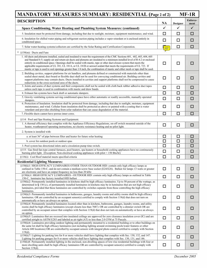
MANDATORY MEASURES SUMMARY: RESIDENTIAL (Page 2 of 2) MF-1R DESCRIPTION NA Designer
Enforce-ment
Space Conditioning, Water Heating and Plumbing System Measures: (continued) 5. Insulation must be protected from damage, including that due to sunlight, moisture, equipment maintenance, and wind. 6. Insulation for chilled water piping and refrigerant suction piping includes a vapor retardant or is enclosed entirely in conditioned space. 7. Solar water-heating systems/collectors are certified by the Solar Rating and Certification Corporation.
* §150(m): Ducts and Fans 1. All ducts and plenums installed, sealed and insulated to meet the requirement of the CMC Sections 601, 602, 603, 604, 605
and Standard 6-5; supply-air and return-air ducts and plenums are insulated to a minimum installed level of R-4.2 or enclosed entirely in conditioned space. Openings shall be sealed with mastic, tape or other duct-closure system that meets the applicable requirements of UL 181, UL 181A, or UL 181B or aerosol sealant that meets the requirements of UL 723. If mastic or tape is used to seal openings greater than 1/4 inch, the combination of mastic and either mesh or tape shall be used.
2. Building cavities, support platforms for air handlers, and plenums defined or constructed with materials other than sealed sheet metal, duct board or flexible duct shall not be used for conveying conditioned air. Building cavities and support platforms may contain ducts. Ducts installed in cavities and support platforms shall not be compressed to cause reductions in the cross-sectional area of the ducts.
3. Joints and seams of duct systems and their components shall not be sealed with cloth back rubber adhesive duct tapes unless such tape is used in combination with mastic and draw bands.
4. Exhaust fan systems have back draft or automatic dampers. 5. Gravity ventilating systems serving conditioned space have either automatic or readily accessible, manually operated
dampers. 6. Protection of Insulation. Insulation shall be protected from damage, including that due to sunlight, moisture, equipment
maintenance, and wind. Cellular foam insulation shall be protected as above or painted with a coating that is water retardant and provides shielding from solar radiation that can cause degradation of the material.
7. Flexible ducts cannot have porous inner cores.
§114: Pool and Spa Heating Systems and Equipment. 1. A thermal efficiency that complies with the Appliance Efficiency Regulations, on-off switch mounted outside of the
heater, weatherproof operating instructions, no electric resistance heating and no pilot light. 2. System is installed with:
a. at least 36” of pipe between filter and heater for future solar heating b. cover for outdoor pools or outdoor spas
3. Pool system has directional inlets and a circulation pump time switch. §115: Gas fired fan-type central furnaces, pool heaters, spa heaters or household cooking appliances have no continuously
burning pilot light. (Exception: Non-electrical cooking appliances with pilot < 150 Btu/hr) §118(i): Cool Roof material meets specified criteria Residential Lighting Measures: §150(k)1: HIGH EFFICACY LUMINAIRES OTHER THAN OUTDOOR HID: contain only high efficacy lamps as
outlined in Table 150-C, and do not contain a medium screw base socket (E24/E26). Ballast for lamps 13 watts or greater are electronic and have an output frequency no less than 20 kHz
§150(k)1: HIGH EFFICACY LUMINAIRES - OUTDOOR HID: contain only high efficacy lamps as outlined in Table 150-C, luminaire has factory installed HID ballast
§150(k)2: Permanently installed luminaires in kitchens shall be high efficacy luminaires. Up to 50 percent of the wattage, as determined in § 130 (c), of permanently installed luminaires in kitchens may be in luminaires that are not high efficacy luminaires, provided that these luminaires are controlled by switches separate from those controlling the high efficacy luminaires.
§150(k)3: Permanently installed luminaires in bathrooms, garages, laundry rooms and utility rooms shall be high efficacy luminaires. OR are controlled by an occupant sensor(s) certified to comply with Section 119(d) that does not turn on automatically or have an always on option.
§150(k)4: Permanently installed luminaires located other than in kitchens, bathrooms, garages, laundry rooms, and utility
rooms shall be high efficacy luminaires (except closets less than 70ft2): OR are controlled by a dimmer switch OR are controlled by an occupant sensor that complies with Section 119(d) that does not turn on automatically or have an always on option.
§150(k)5: Luminaires that are recessed into insulated ceilings are approved for zero clearance insulation cover (IC) and are certified airtight to ASTM E283 and labeled as air tight (AT) to less than 2.0 CFM at 75 Pascals.
§150(k)6: Luminaires providing outdoor lighting and permanently mounted to a residential building or to other buildings on the same lot shall be high efficacy luminaires (not including lighting around swimming pools/water features or other Article 680 locations) OR are controlled by occupant sensors with integral photo control certified to comply with Section 119(d).
§150(k)7: Lighting for parking lots for 8 or more vehicles shall have lighting that complies with Sec. 130, 132, and 147. Lighting for parking garages for 8 or more vehicles shall have lighting that complies with Sec. 130, 131, and 146.
§150(k)8: Permanently installed lighting in the enclosed, non-dwelling spaces of low-rise residential buildings with four or more dwelling units shall be high efficacy luminaires OR are controlled by occupant sensor(s) certified to comply with Section 119(d).
Residential Compliance Forms April 2005
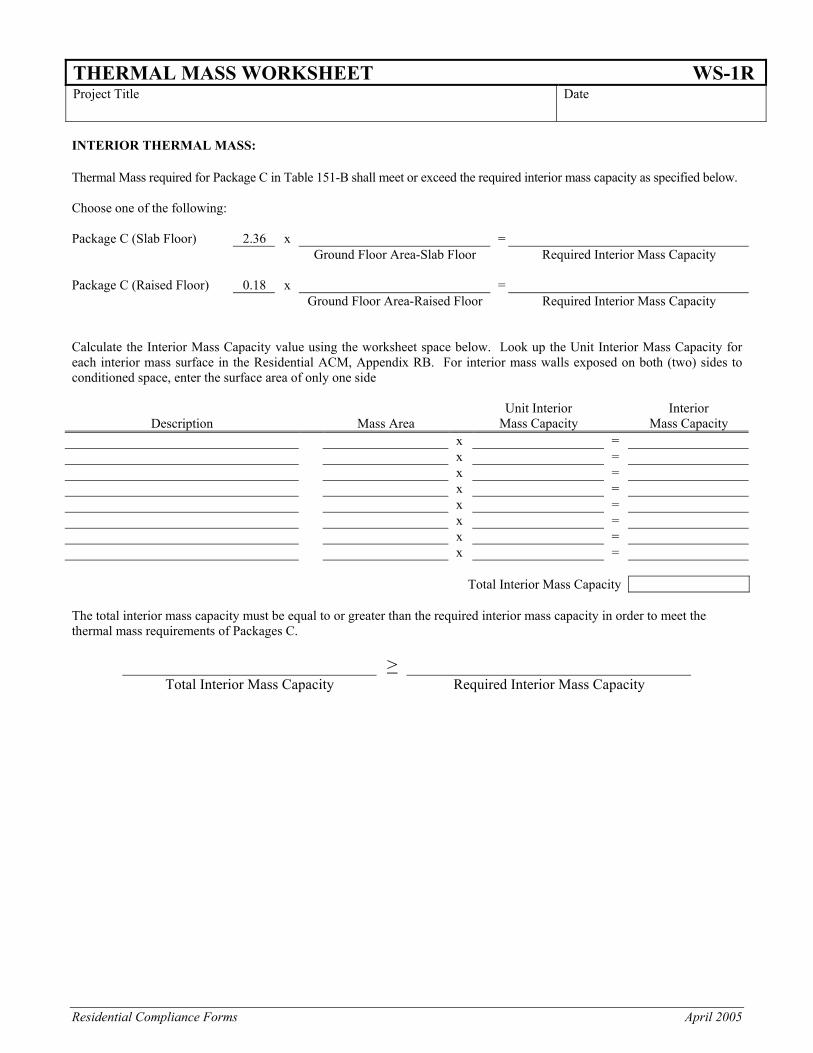
THERMAL MASS WORKSHEET WS-1R Project Title Date
INTERIOR THERMAL MASS: Thermal Mass required for Package C in Table 151-B shall meet or exceed the required interior mass capacity as specified below. Choose one of the following: Package C (Slab Floor) 2.36 x = Ground Floor Area-Slab Floor Required Interior Mass Capacity Package C (Raised Floor) 0.18 x = Ground Floor Area-Raised Floor Required Interior Mass Capacity Calculate the Interior Mass Capacity value using the worksheet space below. Look up the Unit Interior Mass Capacity for each interior mass surface in the Residential ACM, Appendix RB. For interior mass walls exposed on both (two) sides to conditioned space, enter the surface area of only one side
Description Mass Area Unit Interior
Mass Capacity Interior
Mass Capacity x = x = x = x = x = x = x = x = Total Interior Mass Capacity The total interior mass capacity must be equal to or greater than the required interior mass capacity in order to meet the thermal mass requirements of Packages C.
>
Total Interior Mass Capacity Required Interior Mass Capacity
Residential Compliance Forms April 2005
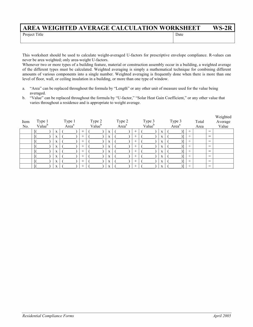
AREA WEIGHTED AVERAGE CALCULATION WORKSHEET WS-2RProject Title Date
This worksheet should be used to calculate weight-averaged U-factors for prescriptive envelope compliance. R-values can never be area weighted; only area-weight U-factors. Whenever two or more types of a building feature, material or construction assembly occur in a building, a weighted average of the different types must be calculated. Weighted averaging is simply a mathematical technique for combining different amounts of various components into a single number. Weighted averaging is frequently done when there is more than one level of floor, wall, or ceiling insulation in a building, or more than one type of window. a. “Area” can be replaced throughout the formula by “Length” or any other unit of measure used for the value being
averaged. b. “Value” can be replaced throughout the formula by “U-factor,” “Solar Heat Gain Coefficient,” or any other value that
varies throughout a residence and is appropriate to weight average.
Item No.
Type 1 Valueb
Type 1 Areaa
Type 2 Valueb
Type 2 Areaa
Type 3 Valueb
Type 3 Areaa
Total Area
Weighted Average Value
[(______) x (______) + (______) x (______) + (______) x (______)] ÷ = [(______) x (______) + (______) x (______) + (______) x (______)] ÷ = [(______) x (______) + (______) x (______) + (______) x (______)] ÷ = [(______) x (______) + (______) x (______) + (______) x (______)] ÷ = [(______) x (______) + (______) x (______) + (______) x (______)] ÷ = [(______) x (______) + (______) x (______) + (______) x (______)] ÷ = [(______) x (______) + (______) x (______) + (______) x (______)] ÷ = [(______) x (______) + (______) x (______) + (______) x (______)] ÷ =
Residential Compliance Forms April 2005
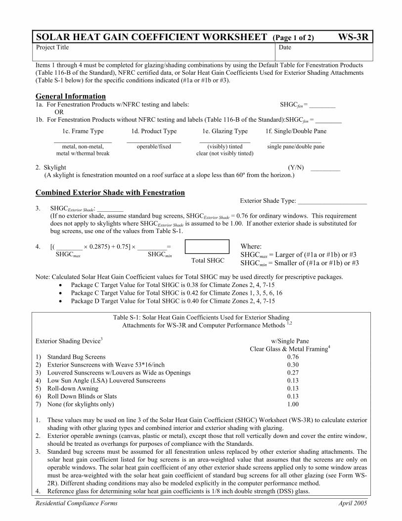
SOLAR HEAT GAIN COEFFICIENT WORKSHEET (Page 1 of 2) WS-3RProject Title Date
Items 1 through 4 must be completed for glazing/shading combinations by using the Default Table for Fenestration Products (Table 116-B of the Standard), NFRC certified data, or Solar Heat Gain Coefficients Used for Exterior Shading Attachments (Table S-1 below) for the specific conditions indicated (#1a or #1b or #3). General Information 1a. For Fenestration Products w/NFRC testing and labels: SHGCfen = ________ OR 1b. For Fenestration Products without NFRC testing and labels (Table 116-B of the Standard):SHGCfen = ________
1c. Frame Type 1d. Product Type 1e. Glazing Type 1f. Single/Double Pane ________________ _______________ ______________ ______________ metal, non-metal, operable/fixed (visibly) tinted single pane/double pane metal w/thermal break clear (not visibly tinted) 2. Skylight (Y/N) _________ (A skylight is fenestration mounted on a roof surface at a slope less than 60º from the horizon.) Combined Exterior Shade with Fenestration Exterior Shade Type: _____________________ 3. SHGCExterior Shade: ________
(If no exterior shade, assume standard bug screens, SHGCExterior Shade = 0.76 for ordinary windows. This requirement does not apply to skylights where SHGCExterior Shade is assumed to be 1.00. If another exterior shade is substituted for bug screens, use one of the values from Table S-1.
4. [( ________ × 0.2875) + 0.75] × _________= SHGCmax SHGCmin Note: Calculated Solar Heat Gain Coefficient values for Total SHGC may be used directly for prescriptive packages.
• Package C Target Value for Total SHGC is 0.38 for Climate Zones 2, 4, 7-15 • Package C Target Value for Total SHGC is 0.42 for Climate Zones 1, 3, 5, 6, 16 • Package D Target Value for Total SHGC is 0.40 for Climate Zones 2, 4, 7-15
Table S-1: Solar Heat Gain Coefficients Used for Exterior Shading
Attachments for WS-3R and Computer Performance Methods 1,2
Exterior Shading Device3 w/Single Pane Clear Glass & Metal Framing4 1) Standard Bug Screens 0.76 2) Exterior Sunscreens with Weave 53*16/inch 0.30 3) Louvered Sunscreens w/Louvers as Wide as Openings 0.27 4) Low Sun Angle (LSA) Louvered Sunscreens 0.13 5) Roll-down Awning 0.13 6) Roll Down Blinds or Slats 0.13 7) None (for skylights only) 1.00 1. These values may be used on line 3 of the Solar Heat Gain Coefficient (SHGC) Worksheet (WS-3R) to calculate exterior
shading with other glazing types and combined interior and exterior shading with glazing. 2. Exterior operable awnings (canvas, plastic or metal), except those that roll vertically down and cover the entire window,
should be treated as overhangs for purposes of compliance with the Standards. 3. Standard bug screens must be assumed for all fenestration unless replaced by other exterior shading attachments. The
solar heat gain coefficient listed for bug screens is an area-weighted value that assumes that the screens are only on operable windows. The solar heat gain coefficient of any other exterior shade screens applied only to some window areas must be area-weighted with the solar heat gain coefficient of standard bug screens for all other glazing (see Form WS-2R). Different shading conditions may also be modeled explicitly in the computer performance method.
4. Reference glass for determining solar heat gain coefficients is 1/8 inch double strength (DSS) glass.
Total SHGC
Where: SHGCmax = Larger of (#1a or #1b) or #3 SHGCmin = Smaller of (#1a or #1b) or #3
Residential Compliance Forms April 2005
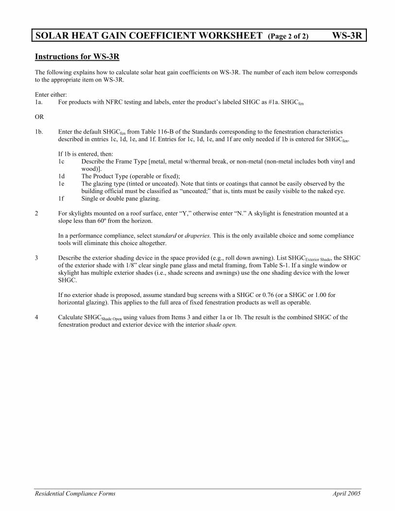
SOLAR HEAT GAIN COEFFICIENT WORKSHEET (Page 2 of 2) WS-3R Instructions for WS-3R The following explains how to calculate solar heat gain coefficients on WS-3R. The number of each item below corresponds to the appropriate item on WS-3R. Enter either: 1a. For products with NFRC testing and labels, enter the product’s labeled SHGC as #1a. SHGCfen OR 1b. Enter the default SHGCfen from Table 116-B of the Standards corresponding to the fenestration characteristics
described in entries 1c, 1d, 1e, and 1f. Entries for 1c, 1d, 1e, and 1f are only needed if 1b is entered for SHGCfen.
If 1b is entered, then: 1c Describe the Frame Type [metal, metal w/thermal break, or non-metal (non-metal includes both vinyl and
wood)]. 1d The Product Type (operable or fixed); 1e The glazing type (tinted or uncoated). Note that tints or coatings that cannot be easily observed by the
building official must be classified as “uncoated;” that is, tints must be easily visible to the naked eye. 1f Single or double pane glazing.
2 For skylights mounted on a roof surface, enter “Y,” otherwise enter “N.” A skylight is fenestration mounted at a
slope less than 60º from the horizon.
In a performance compliance, select standard or draperies. This is the only available choice and some compliance tools will eliminate this choice altogether.
3 Describe the exterior shading device in the space provided (e.g., roll down awning). List SHGCExterior Shade, the SHGC
of the exterior shade with 1/8” clear single pane glass and metal framing, from Table S-1. If a single window or skylight has multiple exterior shades (i.e., shade screens and awnings) use the one shading device with the lower SHGC.
If no exterior shade is proposed, assume standard bug screens with a SHGC or 0.76 (or a SHGC or 1.00 for horizontal glazing). This applies to the full area of fixed fenestration products as well as operable.
4 Calculate SHGCShade Open using values from Items 3 and either 1a or 1b. The result is the combined SHGC of the
fenestration product and exterior device with the interior shade open.
Residential Compliance Forms December 2005
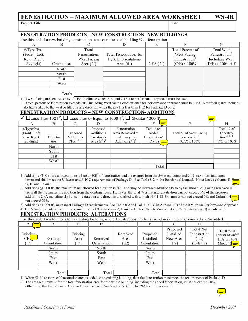
FENESTRATION – MAXIMUM ALLOWED AREA WORKSHEET WS-4RProject Title Date
FENESTRATION PRODUCTS – NEW CONSTRUCTION- NEW BUILDINGS Use this table for new building construction to account for total building % of fenestration.
A B C D E F G #/Type/Pos. (Front, Left, Rear, Right,
Skylight) Orientation
Total Fenestration, West Facing
Area (ft2)
Total Fenestration for N, S, E Orientations
Area (ft2) CFA (ft2)
Total Percent of West Facing Fenestration1
(C/E) x 100%
Total % of Fenestration2
Including West (D/E) x 100% + F
North South East
West
Totals 1) If west facing area exceeds 5% of CFA in climate zones 2, 4, and 7-15, the performance approach must be used. 2) If total percent of fenestration exceeds 20% including West facing orientations then performance approach must be used. West facing area includes
skylights tilted to the west or tilted in any direction when the pitch is less than 1:12 for Package D only. FENESTRATION PRODUCTS – NEW CONSTRUCTION- ADDITIONS
Less than 100 ft2, Less than or Equal to 1000 ft2, Greater 1000 ft2
A B C D E F G H #/Type/Pos. (Front, Left, Rear, Right,
Skylight) Orienta-
tion
Proposed Addition’s CFA1, 2, 3
Proposed Addition’s
Fenestration Area (ft2)4
Fenestration Area Removed to
make way for Addition (ft2)2
Total Area Added
Fenestration2 (D - E)
Total % of West Facing Fenestration2 (G/C) x 100%
Total % of Fenestra- tion 2, 3, 4
(F/C) x 100% North South East
West4 Total 1) Additions ≤100 sf are allowed to install up to 50ft2 of fenestration and are exempt from the 5% west facing and 20% maximum total area
limits and shall meet the U-factor and SHGC requirements of Package D. See Table 8-2 in the Residential Manual. Note: Leave columns E, F, G, H, and I blank.
2) Additions ≤1,000 ft², the maximum net allowed fenestration is 20% and may be increased additionally to by the amount of glazing removed in the wall that separates the addition from the existing house. However, the total West facing fenestration can not exceed 5% of the proposed addition’s CFA including skylights orientated in any direction and tilted with a pitch of < 1:12. Column G can not exceed 5% and Column H can not exceed 20%.
3) Additions >1,000 ft², must meet Package D requirements. See Table 8-2 and Table 151-C in Appendix B of the RM or use Performance Approach. 4) The 5%west orientation restrictions are only for Climate zones 2, 4, and 7-15; for Climate Zones 2, 4 and 7-15 enter zero (0) in column E. FENESTRATION PRODUCTS: ALTERATIONS Use this table for alterations to an existing building where fenestrations products (windows) are being removed and/or added.
A B C D E F G H I
Existing CFA (ft2)
Existing Orientation
Existing Area (ft2)
Removed Orientation
Removed Area (ft2)
Proposed Installed
Orientation
Proposed Installed
New Area (ft2)
Total Net Fenestration
(ft2) (C-E+G)
Total % of Fenestra-tion1, 2 (H/A) x 100% Max of 20%
North North North South South South East East East West West West
Total Total Total
1) When 50 ft2 or more of fenestration area is added to an existing building, then the fenestration must meet the requirements of Package D. 2) The area requirement for the total fenestration area for the whole building, including the added fenestration, must not exceed 20%.
Otherwise, the Performance Approach must be used. See Section 8.3.3 in the RM for further details.
Residential Compliance Forms December 2005
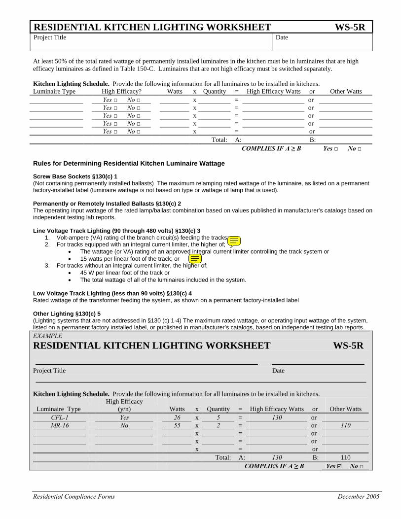
RESIDENTIAL KITCHEN LIGHTING WORKSHEET WS-5R Project Title Date
At least 50% of the total rated wattage of permanently installed luminaires in the kitchen must be in luminaires that are high efficacy luminaires as defined in Table 150-C. Luminaires that are not high efficacy must be switched separately. Kitchen Lighting Schedule. Provide the following information for all luminaires to be installed in kitchens. Luminaire Type High Efficacy? Watts x Quantity = High Efficacy Watts or Other Watts Yes □ No □ x = or Yes □ No □ x = or Yes □ No □ x = or Yes □ No □ x = or Yes □ No □ x = or Total: A: B: COMPLIES IF A ≥ B Yes □ No □ Rules for Determining Residential Kitchen Luminaire Wattage Screw Base Sockets §130(c) 1 (Not containing permanently installed ballasts) The maximum relamping rated wattage of the luminaire, as listed on a permanent factory-installed label (luminaire wattage is not based on type or wattage of lamp that is used). Permanently or Remotely Installed Ballasts §130(c) 2 The operating input wattage of the rated lamp/ballast combination based on values published in manufacturer’s catalogs based on independent testing lab reports. Line Voltage Track Lighting (90 through 480 volts) §130(c) 3
1. Volt-ampere (VA) rating of the branch circuit(s) feeding the tracks; or 2. For tracks equipped with an integral current limiter, the higher of;
• The wattage (or VA) rating of an approved integral current limiter controlling the track system or • 15 watts per linear foot of the track; or
3. For tracks without an integral current limiter, the higher of; • 45 W per linear foot of the track or • The total wattage of all of the luminaires included in the system.
Low Voltage Track Lighting (less than 90 volts) §130(c) 4 Rated wattage of the transformer feeding the system, as shown on a permanent factory-installed label Other Lighting §130(c) 5 (Lighting systems that are not addressed in §130 (c) 1-4) The maximum rated wattage, or operating input wattage of the system, listed on a permanent factory installed label, or published in manufacturer’s catalogs, based on independent testing lab reports. EXAMPLE RESIDENTIAL KITCHEN LIGHTING WORKSHEET WS-5R Project Title Date Kitchen Lighting Schedule. Provide the following information for all luminaires to be installed in kitchens.
Luminaire Type
High Efficacy (y/n)
Watts
x
Quantity
=
High Efficacy Watts
or
Other Watts
CFL-1 Yes 26 x 5 = 130 or MR-16 No 55 x 2 = or 110
x = or x = or x = or Total: A: 130 B: 110 COMPLIES IF A ≥ B Yes No □
Residential Compliance Forms December 2005
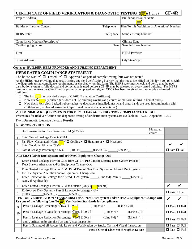
CERTIFICATE OF FIELD VERIFICATION & DIAGNOSTIC TESTING (Page 1 of 8) CF-4R Project Address Builder or Installer Name Builder or Installer Contact Telephone Plan/Permit (Additions or Alterations) Number
HERS Rater Telephone Sample Group Number Compliance Method (Prescriptive) Climate Zone Certifying Signature Date Sample House Number
Firm HERS Provider
Street Address: City/State/Zip:
Copies to: BUILDER, HERS PROVIDER AND BUILDING DEPARTMENT
HERS RATER COMPLIANCE STATEMENT The house was: Tested Approved as part of sample testing, but was not tested As the HERS rater providing diagnostic testing and field verification, I certify that the house identified on this form complies with the diagnostic tested compliance requirements as checked on this form. The HERS rater must check and verify that the new distribution system is fully ducted and correct tape is used before a CF-4R may be released on every tested building. The HERS rater must not release the CF-4R until a properly completed and signed CF-6R has been received for the sample and tested buildings. The installer has provided a copy of CF-6R (Installation Certificate).
New ducts are fully ducted (i.e., does not use building cavities as plenums or platform returns in lieu of ducts). New ducts with cloth backed, rubber adhesive duct tape is installed, mastic and draw bands are used in combination with
cloth backed, rubber adhesive duct tape to seal leaks at duct connections.). MINIMUM REQUIREMENTS FOR DUCT LEAKAGE REDUCTION COMPLIANCE CREDIT
Procedures for field verification and diagnostic testing of air distribution systems are available in RACM, Appendix RC4.3. Duct Diagnostic Leakage Testing Results NEW CONSTRUCTION:
Duct Pressurization Test Results (CFM @ 25 Pa) Measured Values
1 Enter Tested Leakage Flow in CFM:
2 Fan Flow: Calculated (Nominal: Cooling Heating) or Measured Enter Total Fan Flow in CFM:
3 Pass if Leakage Percentage < 6% [ 100 x [ (Line # 1) / (Line # 2)]] Pass Fail
ALTERATIONS: Duct System and/or HVAC Equipment Change-Out
4 Enter Tested Leakage Flow in CFM from CF-6R: Pre-Test of Existing Duct System Prior to Duct System Alteration and/or Equipment Change-Out.
5 Enter Tested Leakage Flow in CFM: Final Test of New Duct System or Altered Duct System for Duct System Alteration and/or Equipment Change-Out.
6 Enter Reduction in Leakage for Altered Duct System [_____(Line # 4) Minus (Line # 5)] (Only if Applicable)
7 Enter Tested Leakage Flow in CFM to Outside (Only if Applicable) 8
Entire New Duct System - Pass if Leakage Percentage < 6% [100 x [ (Line # 5) / Line # 2)]] Pass Fail
TEST OR VERIFICATION STANDARDS: For Altered Duct System and/or HVAC Equipment Change-Out Use one of the following four Test or Verification Standards for compliance:
9 Pass if Leakage Percentage < 15% [100 x [ (Line # 5) / (Line # 2)]] Pass Fail
10 Pass if Leakage to Outside Percentage < 10% [100 x [ (Line # 7) / (Line # 2)]] Pass Fail
11 Pass if Leakage Reduction Percentage > 60% [100 x [ (Line # 6) / (Line # 4)]] and Verification by Smoke Test and Visual Inspection
Pass Fail
Pass if Sealing of all Accessible Leaks and Verification by Smoke Test and Visual Inspection Pass Fail Pass if One of Lines # 9 through # 12 pass Pass Fail
Residential Compliance Forms December 2005
CERTIFICATE OF FIELD VERIFICATION & DIAGNOSTIC TESTING (Page 2 of 8) CF-4RProject Address Builders Name
Copies to: BUILDER, HERS PROVIDER AND BUILDING DEPARTMENT
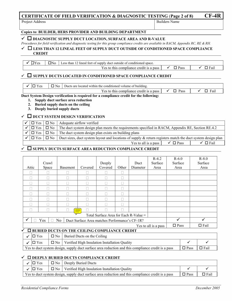
DIAGNOSTIC SUPPLY DUCT LOCATION, SURFACE AREA AND R-VALUE Procedures for field verification and diagnostic testing for this group compliance credits are available in RACM, Appendix RC, RE & RH.
LESS THAN 12 LINEAL FEET OF SUPPLY DUCT OUTSIDE OF CONDITIONED SPACE COMPLIANCE CREDIT
Yes No Less than 12 lineal feet of supply duct outside of conditioned space.
Yes to this compliance credit is a pass Pass Fail
SUPPLY DUCTS LOCATED IN CONDITIONED SPACE COMPLIANCE CREDIT
Yes No Ducts are located within the conditioned volume of building. Yes to this compliance credit is a pass Pass Fail
Duct System Design verification is required for a compliance credit for the following: 1. Supply duct surface area reduction 2. Buried supply ducts on the ceiling 3. Deeply buried supply ducts
DUCT SYSTEM DESIGN VERIFICATION Yes No Adequate airflow verified Yes No The duct system design plan meets the requirements specified in RACM, Appendix RE, Section RE.4.2 Yes No The duct system design plan exists on building plans Yes No Duct sizes, duct system layout and locations of supply & return registers match the duct system design plan
Yes to all is a pass Pass Fail SUPPLY DUCTS SURFACE AREA REDUCTION COMPLIANCE CREDIT
Attic Crawl Space Basement Covered
Deeply Covered Other
Duct Diameter
R-4.2 Surface
Area
R-6.0 Surface
Area
R-8.0 Surface Area
Total Surface Area for Each R-Value = Yes No Duct Surface Area matches Performance’s CF-1R?
Yes to all is a pass Pass Fail BURIED DUCTS ON THE CEILING COMPLIANCE CREDIT
Yes No Buried Ducts on the Ceiling
Yes No Verified High Insulation Installation Quality Yes to duct system design, supply duct surface area reduction and this compliance credit is a pass Pass Fail
DEEPLY BURIED DUCTS COMPLIANCE CREDIT
Yes No Deeply Buried Ducts
Yes No Verified High Insulation Installation Quality Yes to duct system design, supply duct surface area reduction and this compliance credit is a pass Pass Fail
Residential Compliance Forms April 2005
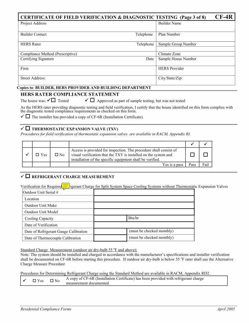
CERTIFICATE OF FIELD VERIFICATION & DIAGNOSTIC TESTING (Page 3 of 8) CF-4RProject Address Builder Name Builder Contact Telephone Plan Number
HERS Rater Telephone Sample Group Number Compliance Method (Prescriptive) Climate Zone Certifying Signature Date Sample House Number
Firm HERS Provider
Street Address: City/State/Zip:
Copies to: BUILDER, HERS PROVIDER AND BUILDING DEPARTMENT
HERS RATER COMPLIANCE STATEMENT The house was: Tested Approved as part of sample testing, but was not tested
As the HERS rater providing diagnostic testing and field verification, I certify that the house identified on this form complies with the diagnostic tested compliance requirements as checked on this form.
The installer has provided a copy of CF-6R (Installation Certificate).
THERMOSTATIC EXPANSION VALVE (TXV) Procedures for field verification of thermostatic expansion valves are available in RACM, Appendix RI.
Yes No Access is provided for inspection. The procedure shall consist of visual verification that the TXV is installed on the system and installation of the specific equipment shall be verified.
Yes is a pass Pass Fail
REFRIGERANT CHARGE MEASUREMENT Verification for Required Refrigerant Charge for Split System Space Cooling Systems without Thermostatic Expansion Valves
Outdoor Unit Serial # Location
Outdoor Unit Make
Outdoor Unit Model
Cooling Capacity Btu/hr
Date of Verification
Date of Refrigerant Gauge Calibration (must be checked monthly)
Date of Thermocouple Calibration (must be checked monthly) Standard Charge Measurement (outdoor air dry-bulb 55 oF and above): Note: The system should be installed and charged in accordance with the manufacturer’s specifications and installer verification shall be documented on CF-6R before starting this procedure. If outdoor air dry-bulb is below 55 oF rater shall use the Alternative Charge Measure Procedure
Procedures for Determining Refrigerant Charge using the Standard Method are available in RACM, Appendix RD2.
Yes No A copy of CF-6R (Installation Certificate) has been provided with refrigerant charge measurement documented.
Residential Compliance Forms December 2005
CERTIFICATE OF FIELD VERIFICATION & DIAGNOSTIC TESTING (Page 4 of 8) CF-4RProject Address Builders Name
Copies to: BUILDER, HERS PROVIDER AND BUILDING DEPARTMENT
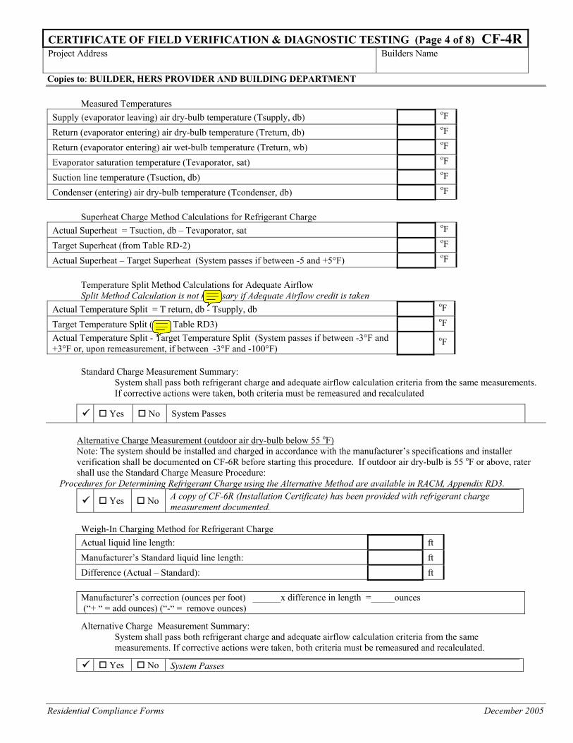
Measured Temperatures Supply (evaporator leaving) air dry-bulb temperature (Tsupply, db) oF
Return (evaporator entering) air dry-bulb temperature (Treturn, db) oF
Return (evaporator entering) air wet-bulb temperature (Treturn, wb) oF
Evaporator saturation temperature (Tevaporator, sat) oF
Suction line temperature (Tsuction, db) oF
Condenser (entering) air dry-bulb temperature (Tcondenser, db) oF
Superheat Charge Method Calculations for Refrigerant Charge Actual Superheat = Tsuction, db – Tevaporator, sat oF
Target Superheat (from Table RD-2) oF
Actual Superheat – Target Superheat (System passes if between -5 and +5°F) oF
Temperature Split Method Calculations for Adequate Airflow Split Method Calculation is not necessary if Adequate Airflow credit is taken
Actual Temperature Split = T return, db - Tsupply, db oF
Target Temperature Split (from Table RD3) oF Actual Temperature Split - Target Temperature Split (System passes if between -3°F and +3°F or, upon remeasurement, if between -3°F and -100°F)
oF
Standard Charge Measurement Summary:
System shall pass both refrigerant charge and adequate airflow calculation criteria from the same measurements. If corrective actions were taken, both criteria must be remeasured and recalculated
Yes No System Passes
Alternative Charge Measurement (outdoor air dry-bulb below 55 oF) Note: The system should be installed and charged in accordance with the manufacturer’s specifications and installer verification shall be documented on CF-6R before starting this procedure. If outdoor air dry-bulb is 55 oF or above, rater shall use the Standard Charge Measure Procedure:
Procedures for Determining Refrigerant Charge using the Alternative Method are available in RACM, Appendix RD3.
Yes No A copy of CF-6R (Installation Certificate) has been provided with refrigerant charge measurement documented.
Weigh-In Charging Method for Refrigerant Charge Actual liquid line length: ft
Manufacturer’s Standard liquid line length: ft
Difference (Actual – Standard): ft Manufacturer’s correction (ounces per foot) ______x difference in length =_____ounces (“+ “ = add ounces) (“-“ = remove ounces)
Alternative Charge Measurement Summary: System shall pass both refrigerant charge and adequate airflow calculation criteria from the same measurements. If corrective actions were taken, both criteria must be remeasured and recalculated.
Yes No System Passes
Residential Compliance Forms December 2005
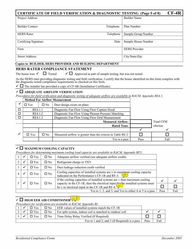
CERTIFICATE OF FIELD VERIFICATION & DIAGNOSTIC TESTING (Page 5 of 8) CF-4RProject Address Builder Name Builder Contact Telephone Plan Number
HERS Rater Telephone Sample Group Number Certifying Signature Date Sample House Number
Firm HERS Provider
Street Address: City/State/Zip:
Copies to: BUILDER, HERS PROVIDER AND BUILDING DEPARTMENT
HERS RATER COMPLIANCE STATEMENT The house was: Tested Approved as part of sample testing, but was not tested
As the HERS rater providing diagnostic testing and field verification, I certify that the house identified on this form complies with the diagnostic tested compliance requirements as checked on this form.
The installer has provided a copy of CF-6R (Installation Certificate). ADEQUATE AIRFLOW VERIFICATION
Procedures for field verification and diagnostic testing of adequate airflow are available in RACM, Appendix RE4.1. Method For Airflow Measurement
Yes No Duct design exists on plans RE4.1.1 Diagnostic Fan Flow Using Flow Capture Hood RE4.1.2 Diagnostic Fan Flow Using Plenum Pressure Matching RE4.1.3 Diagnostic Fan Flow Using Flow Grid Measurement
Measured Airflow: Total CFM Rated Tons: cfm/ton
Yes No Measured airflow is greater than the criteria in Table RE-2 Yes is a pass Pass Fail
MAXIMUM COOLING CAPACITY Procedures for determining maximum cooling load capacity are available in RACM, Appendix RF3.
1 Yes No Adequate airflow verified (see adequate airflow credit) 2 Yes No Refrigerant charge or TXV 3 Yes No Duct leakage reduction credit verified 4 Yes No Cooling capacities of installed systems are ≤ to maximum cooling capacity
indicated on the Performance’s CF-1R and RF-3. 5 Yes No
If the cooling capacities of installed systems are > than maximum cooling capacity in the CF-1R, then the electrical input for the installed systems must be ≤ to electrical input in the CF-1R and RF-4.
Yes to 1, 2, and 3; and Yes to either 4 or 5 is a pass Pass Fail
HIGH EER AIR CONDITIONER Procedures for verification are available in RACM, Appendix RI.
1 Yes No EER values of installed systems match the CF-1R 2 Yes No For split system, indoor coil is matched to outdoor coil 3 Yes No Time Delay Relay Verified (If Required) Yes to 1 and 2; and 3 (If Required) is a pass Pass Fail
Residential Compliance Forms April 2005
CERTIFICATE OF FIELD VERIFICATION & DIAGNOSTIC TESTING (Page 6 of 8) CF-4RProject Address Builder Name Builder Contact Telephone Plan Number
HERS Rater Telephone Sample Group Number Certifying Signature Date Sample House Number
Firm HERS Provider
Street Address: City/State/Zip:
Copies to: BUILDER, HERS PROVIDER AND BUILDING DEPARTMENT
HERS RATER COMPLIANCE STATEMENT The house was: Tested Approved as part of sample testing, but was not tested
As the HERS rater providing diagnostic testing and field verification, I certify that the house identified on this form complies with the diagnostic tested compliance requirements as checked on this form.
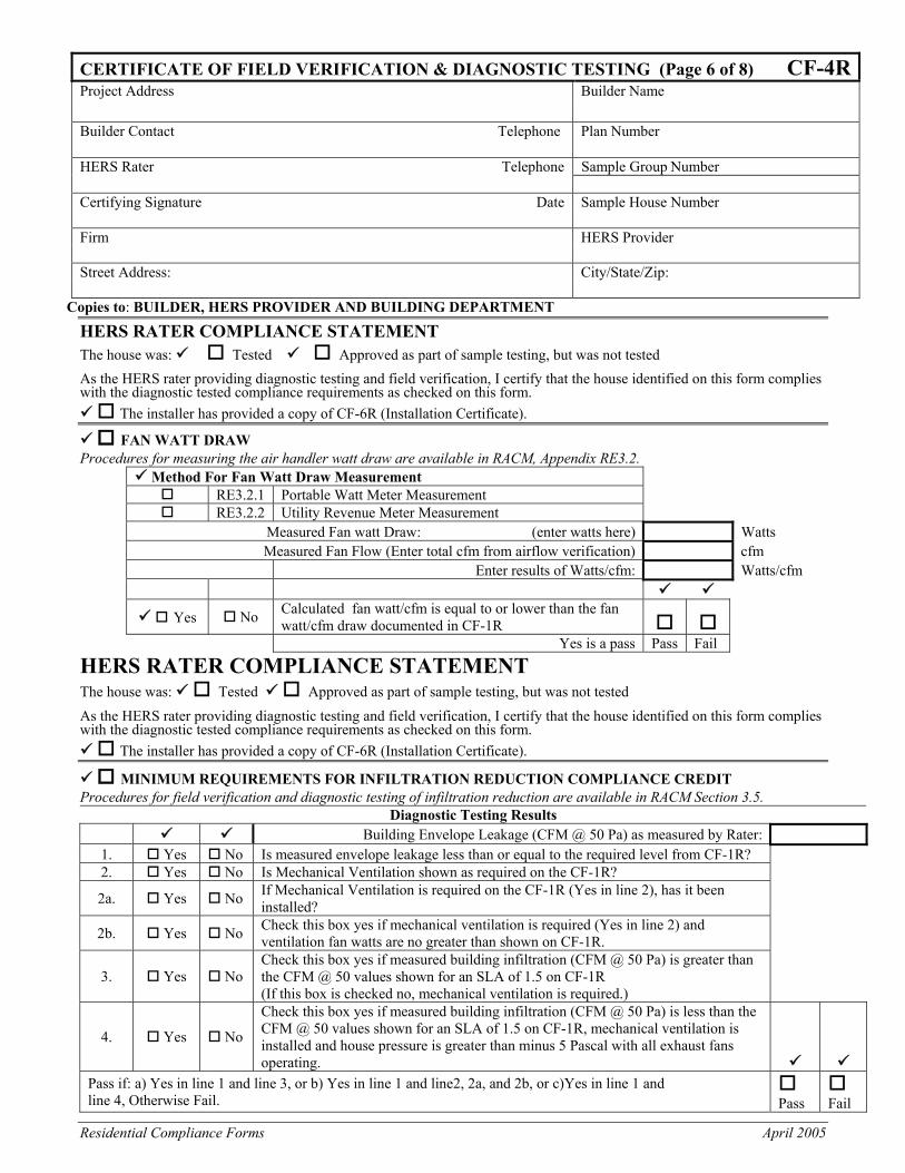
The installer has provided a copy of CF-6R (Installation Certificate). FAN WATT DRAW
Procedures for measuring the air handler watt draw are available in RACM, Appendix RE3.2. Method For Fan Watt Draw Measurement
RE3.2.1 Portable Watt Meter Measurement RE3.2.2 Utility Revenue Meter Measurement
Measured Fan watt Draw: (enter watts here) Watts Measured Fan Flow (Enter total cfm from airflow verification) cfm
Enter results of Watts/cfm: Watts/cfm
Yes No Calculated fan watt/cfm is equal to or lower than the fan watt/cfm draw documented in CF-1R
Yes is a pass Pass Fail
HERS RATER COMPLIANCE STATEMENT The house was: Tested Approved as part of sample testing, but was not tested As the HERS rater providing diagnostic testing and field verification, I certify that the house identified on this form complies with the diagnostic tested compliance requirements as checked on this form.
The installer has provided a copy of CF-6R (Installation Certificate).
MINIMUM REQUIREMENTS FOR INFILTRATION REDUCTION COMPLIANCE CREDIT Procedures for field verification and diagnostic testing of infiltration reduction are available in RACM Section 3.5.
Diagnostic Testing Results Building Envelope Leakage (CFM @ 50 Pa) as measured by Rater:
1. Yes No Is measured envelope leakage less than or equal to the required level from CF-1R? 2. Yes No Is Mechanical Ventilation shown as required on the CF-1R?
2a. Yes No If Mechanical Ventilation is required on the CF-1R (Yes in line 2), has it been installed?
2b. Yes No Check this box yes if mechanical ventilation is required (Yes in line 2) and ventilation fan watts are no greater than shown on CF-1R.
3. Yes No Check this box yes if measured building infiltration (CFM @ 50 Pa) is greater than the CFM @ 50 values shown for an SLA of 1.5 on CF-1R (If this box is checked no, mechanical ventilation is required.)
4. Yes No
Check this box yes if measured building infiltration (CFM @ 50 Pa) is less than the CFM @ 50 values shown for an SLA of 1.5 on CF-1R, mechanical ventilation is installed and house pressure is greater than minus 5 Pascal with all exhaust fans operating.
Pass if: a) Yes in line 1 and line 3, or b) Yes in line 1 and line2, 2a, and 2b, or c)Yes in line 1 and line 4, Otherwise Fail.
Pass
Fail
Residential Compliance Forms April 2005
CERTIFICATE OF FIELD VERIFICATION & DIAGNOSTIC TESTING (Page 7 of 8) CF-4R Project Address Builder Name Builder Contact Telephone Plan Number
HERS Rater Telephone Sample Group Number Certifying Signature Date Sample House Number
Firm HERS Provider
Street Address: City/State/Zip:
Copies to: BUILDER, HERS PROVIDER AND BUILDING DEPARTMENT
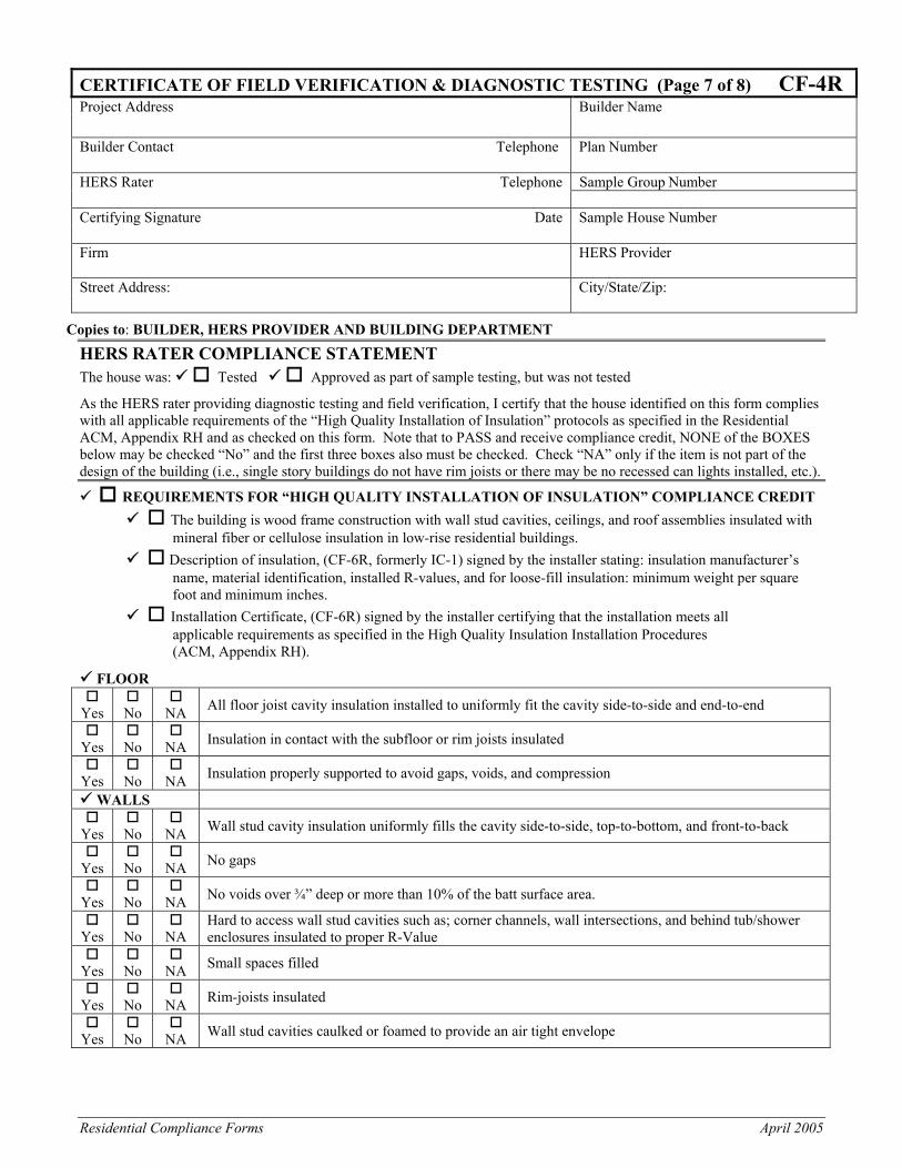
HERS RATER COMPLIANCE STATEMENT The house was: Tested Approved as part of sample testing, but was not tested
As the HERS rater providing diagnostic testing and field verification, I certify that the house identified on this form complies with all applicable requirements of the “High Quality Installation of Insulation” protocols as specified in the Residential ACM, Appendix RH and as checked on this form. Note that to PASS and receive compliance credit, NONE of the BOXES below may be checked “No” and the first three boxes also must be checked. Check “NA” only if the item is not part of the design of the building (i.e., single story buildings do not have rim joists or there may be no recessed can lights installed, etc.).
REQUIREMENTS FOR “HIGH QUALITY INSTALLATION OF INSULATION” COMPLIANCE CREDIT The building is wood frame construction with wall stud cavities, ceilings, and roof assemblies insulated with
mineral fiber or cellulose insulation in low-rise residential buildings. Description of insulation, (CF-6R, formerly IC-1) signed by the installer stating: insulation manufacturer’s
name, material identification, installed R-values, and for loose-fill insulation: minimum weight per square foot and minimum inches.
Installation Certificate, (CF-6R) signed by the installer certifying that the installation meets all applicable requirements as specified in the High Quality Insulation Installation Procedures (ACM, Appendix RH).
FLOOR
Yes
No
NA All floor joist cavity insulation installed to uniformly fit the cavity side-to-side and end-to-end
Yes
No
NA Insulation in contact with the subfloor or rim joists insulated
Yes
No
NA Insulation properly supported to avoid gaps, voids, and compression
WALLS
Yes
No
NA Wall stud cavity insulation uniformly fills the cavity side-to-side, top-to-bottom, and front-to-back
Yes
No
NA No gaps
Yes
No
NA No voids over ¾” deep or more than 10% of the batt surface area.
Yes
No
NA
Hard to access wall stud cavities such as; corner channels, wall intersections, and behind tub/shower enclosures insulated to proper R-Value
Yes
No
NA Small spaces filled
Yes
No
NA Rim-joists insulated
Yes
No
NA Wall stud cavities caulked or foamed to provide an air tight envelope
Residential Compliance Forms April 2005
CERTIFICATE OF FIELD VERIFICATION & DIAGNOSTIC TESTING (Page 8 of 8) CF-4RProject Address Builders Name
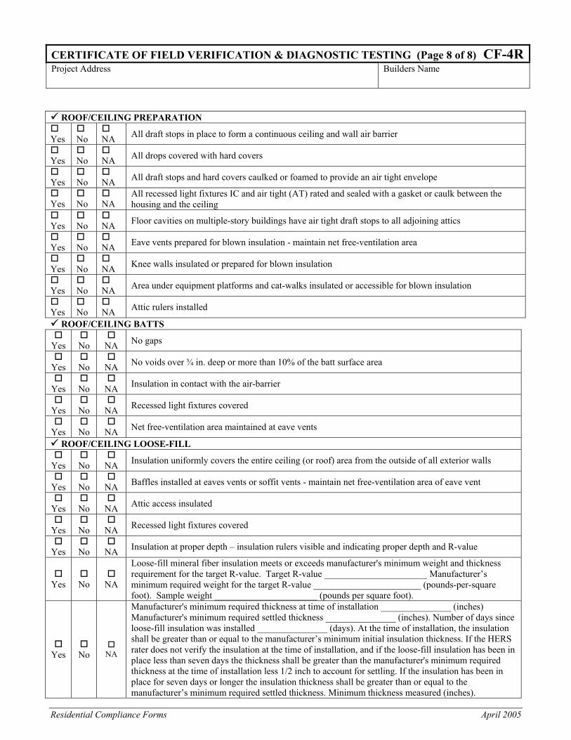
ROOF/CEILING PREPARATION
Yes
No
NA All draft stops in place to form a continuous ceiling and wall air barrier
Yes
No
NA All drops covered with hard covers
Yes
No
NA All draft stops and hard covers caulked or foamed to provide an air tight envelope
Yes
No
NA
All recessed light fixtures IC and air tight (AT) rated and sealed with a gasket or caulk between the housing and the ceiling
Yes
No
NA Floor cavities on multiple-story buildings have air tight draft stops to all adjoining attics
Yes
No
NA Eave vents prepared for blown insulation - maintain net free-ventilation area
Yes
No
NA Knee walls insulated or prepared for blown insulation
Yes
No
NA Area under equipment platforms and cat-walks insulated or accessible for blown insulation
Yes
No
NA Attic rulers installed
ROOF/CEILING BATTS
Yes
No
NA No gaps
Yes
No
NA No voids over ¾ in. deep or more than 10% of the batt surface area
Yes
No
NA Insulation in contact with the air-barrier
Yes
No
NA Recessed light fixtures covered
Yes
No
NA Net free-ventilation area maintained at eave vents
ROOF/CEILING LOOSE-FILL
Yes
No
NA Insulation uniformly covers the entire ceiling (or roof) area from the outside of all exterior walls
Yes
No
NA Baffles installed at eaves vents or soffit vents - maintain net free-ventilation area of eave vent
Yes
No
NA Attic access insulated
Yes
No
NA Recessed light fixtures covered
Yes
No
NA Insulation at proper depth – insulation rulers visible and indicating proper depth and R-value
Yes
No
NA
Loose-fill mineral fiber insulation meets or exceeds manufacturer's minimum weight and thickness requirement for the target R-value. Target R-value ______________________ Manufacturer’s minimum required weight for the target R-value _______________________ (pounds-per-square foot). Sample weight ______________________ (pounds per square foot).
Yes
No
NA
Manufacturer's minimum required thickness at time of installation _______________ (inches) Manufacturer's minimum required settled thickness _______________ (inches). Number of days since loose-fill insulation was installed _______________ (days). At the time of installation, the insulation shall be greater than or equal to the manufacturer’s minimum initial insulation thickness. If the HERS rater does not verify the insulation at the time of installation, and if the loose-fill insulation has been in place less than seven days the thickness shall be greater than the manufacturer's minimum required thickness at the time of installation less 1/2 inch to account for settling. If the insulation has been in place for seven days or longer the insulation thickness shall be greater than or equal to the manufacturer’s minimum required settled thickness. Minimum thickness measured (inches).
Residential Compliance Forms September 2005
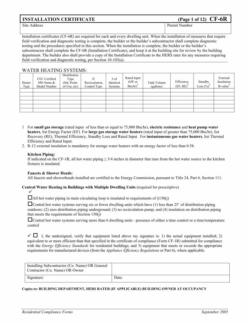
INSTALLATION CERTIFICATE (Page 1 of 12) CF-6R Site Address Permit Number
Installation certificates (CF-6R) are required for each and every dwelling unit. When the installation of measures that require field verification and diagnostic testing is complete, the builder or the builder’s subcontractor shall complete diagnostic testing and the procedures specified in this section. When the installation is complete, the builder or the builder’s subcontractor shall complete the CF-6R (Installation Certificate), and keep it at the building site for review by the building department. The builder also shall provide a copy of the Installation Certificate to the HERS rater for any measures requiring field verification and diagnostic testing, per Section 10-103(a). WATER HEATING SYSTEMS:
Heater Type
CEC Certified Mfr Name &
Model Number
Distribution Type
(Std, Point-of-Use, etc)
If Recirculation, Control Type
# of Identical Systems
Rated Input (kW or Btu/hr)1
Tank Volume (gallons)
Efficiency (EF, RE)2
Standby Loss (%)2
External Insulation R-value2
1 For small gas storage (rated input of less than or equal to 75,000 Btu/hr), electric resistance and heat pump water
heaters, list Energy Factor (EF). For large gas storage water heaters (rated input of greater than 75,000 Btu/hr), list Recovery (RE), Thermal Efficiency, Standby Loss and Rated Input. For instantaneous gas water heaters, list Thermal Efficiency and Rated Input.
2. R-12 external insulation is mandatory for storage water heaters with an energy factor of less than 0.58.
Kitchen Piping: If indicated on the CF-1R, all hot water piping ≥ 3/4 inches in diameter that runs from the hot water source to the kitchen fixtures is insulated.
Faucets & Shower Heads: All faucets and showerheads installed are certified to the Energy Commission, pursuant to Title 24, Part 6, Section 111.
Central Water Heating in Buildings with Multiple Dwelling Units (required for prescriptive)
All hot water piping in main circulating loop is insulated to requirements of §150(j) Central hot water systems serving six or fewer dwelling units which have (1) less than 25’ of distribution piping
outdoors; (2) zero distribution piping underground; (3) no recirculation pump; and (4) insulation on distribution piping that meets the requirements of Section 150(j)
Central hot water systems serving more than 6 dwelling units - presence of either a time control or a time/temperature control
I, the undersigned, verify that equipment listed above my signature is: 1) the actual equipment installed; 2) equivalent to or more efficient than that specified in the certificate of compliance (Form CF-1R) submitted for compliance with the Energy Efficiency Standards for residential buildings; and 3) equipment that meets or exceeds the appropriate requirements for manufactured devices (from the Appliance Efficiency Regulations or Part 6), where applicable.
Installing Subcontractor (Co. Name) OR General Contractor (Co. Name) OR Owner
Signature: Date:
Copies to: BUILDING DEPARTMENT, HERS RATER (IF APPLICABLE) BUILDING OWNER AT OCCUPANCY
Residential Compliance Forms April 2005
INSTALLATION CERTIFICATE (Page 2 of 12) CF-6R Site Address Permit Number
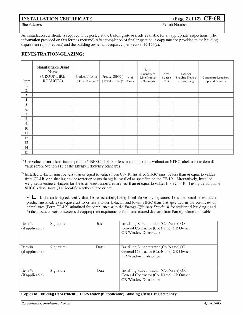
An installation certificate is required to be posted at the building site or made available for all appropriate inspections. (The information provided on this form is required) After completion of final inspection, a copy must be provided to the building department (upon request) and the building owner at occupancy, per Section 10-103(a). FENESTRATION/GLAZING:
Item
Manufacturer/Brand Name
(GROUP LIKE RODUCTS)
Product U-factor1 (≤ CF-1R value) 2
Product SHGC1 (≤CF-1R value)2
# of Panes
Total Quantity of
Like Product (Optional)
Area Square
Feet
Exterior Shading Device
or Overhang Comments/Location/
Special Features 1. 2. 3. 4. 5. 6. 7. 8. 9.
10. 11. 12. 13. 14. 15.
1) Use values from a fenestration product’s NFRC label. For fenestration products without an NFRC label, use the default values from Section 116 of the Energy Efficiency Standards.
2) Installed U-factor must be less than or equal to values from CF-1R. Installed SHGC must be less than or equal to values
from CF-1R, or a shading device (exterior or overhang) is installed as specified on the CF-1R. Alternatively, installed weighted average U-factors for the total fenestration area are less than or equal to values from CF-1R. If using default table SHGC values from §116 identify whether tinted or not.
I, the undersigned, verify that the fenestration/glazing listed above my signature: 1) is the actual fenestration product installed; 2) is equivalent to or has a lower U-factor and lower SHGC than that specified in the certificate of compliance (Form CF-1R) submitted for compliance with the Energy Efficiency Standards for residential buildings; and 3) the product meets or exceeds the appropriate requirements for manufactured devices (from Part 6), where applicable.
Item #s (if applicable)
Signature Date Installing Subcontractor (Co. Name) OR General Contractor (Co. Name) OR Owner OR Window Distributor
Item #s (if applicable)
Signature Date Installing Subcontractor (Co. Name) OR General Contractor (Co. Name) OR Owner OR Window Distributor
Item #s (if applicable)
Signature Date Installing Subcontractor (Co. Name) OR General Contractor (Co. Name) OR Owner OR Window Distributor
Copies to: Building Department , HERS Rater (if applicable) Building Owner at Occupancy
Residential Compliance Forms April 2005
INSTALLATION CERTIFICATE (Page 3 of 12) CF-6R Site Address Permit Number
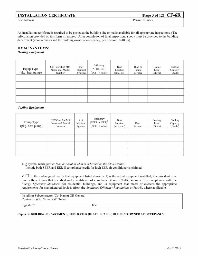
An installation certificate is required to be posted at the building site or made available for all appropriate inspections. (The information provided on this form is required) After completion of final inspection, a copy must be provided to the building department (upon request) and the building owner at occupancy, per Section 10-103(a). HVAC SYSTEMS: Heating Equipment .
Equip Type (pkg. heat pump)
CEC Certified Mfr. Name and Model
Number
# of Identical Systems
Efficiency (AFUE, etc.)1
(≥CF-1R value)
Duct Location
(attic, etc.)
Duct or Piping
R-value
Heating Load
(Btu/hr)
Heating Capacity (Btu/hr)
Cooling Equipment
Equip Type (pkg. heat pump)
CEC Certified Mfr. Name and Model
Number
# of Identical Systems
Efficiency (SEER or EER)1
(≥CF-1R value)
Duct Location
(attic, etc.) Duct
R-value
Cooling Load
(Btu/hr)
Cooling Capacity (Btu/hr)
1. > symbol reads greater than or equal to what is indicated on the CF-1R value.
Include both SEER and EER if compliance credit for high EER air conditioner is claimed. I I, the undersigned, verify that equipment listed above is: 1) is the actual equipment installed, 2) equivalent to or
more efficient than that specified in the certificate of compliance (Form CF-1R) submitted for compliance with the Energy Efficiency Standards for residential buildings, and 3) equipment that meets or exceeds the appropriate requirements for manufactured devices (from the Appliance Efficiency Regulations or Part 6), where applicable.
Installing Subcontractor (Co. Name) OR General Contractor (Co. Name) OR Owner
Signature: Date: Copies to: BUILDING DEPARTMENT, HERS RATER (IF APPLICABLE) BUILDING OWNER AT OCCUPANCY
Residential Compliance Forms December 2005
INSTALLATION CERTIFICATE (Page 4 of 12) CF-6RSite Address Permit Number
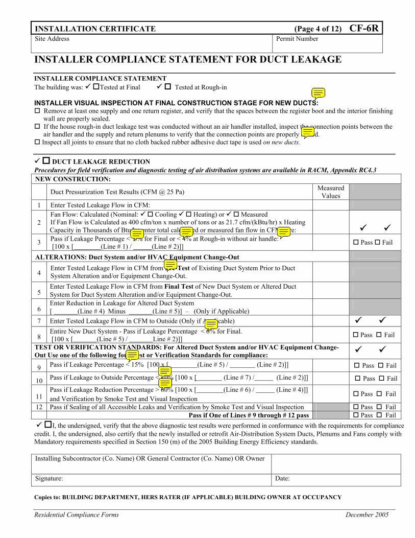
INSTALLER COMPLIANCE STATEMENT FOR DUCT LEAKAGE INSTALLER COMPLIANCE STATEMENT The building was: Tested at Final Tested at Rough-in INSTALLER VISUAL INSPECTION AT FINAL CONSTRUCTION STAGE FOR NEW DUCTS:
Remove at least one supply and one return register, and verify that the spaces between the register boot and the interior finishing wall are properly sealed.
If the house rough-in duct leakage test was conducted without an air handler installed, inspect the connection points between the air handler and the supply and return plenums to verify that the connection points are properly sealed.
Inspect all joints to ensure that no cloth backed rubber adhesive duct tape is used on new ducts.
DUCT LEAKAGE REDUCTION Procedures for field verification and diagnostic testing of air distribution systems are available in RACM, Appendix RC4.3 NEW CONSTRUCTION:
Duct Pressurization Test Results (CFM @ 25 Pa) Measured
Values 1 Enter Tested Leakage Flow in CFM:
2 Fan Flow: Calculated (Nominal: Cooling Heating) or Measured If Fan Flow is Calculated as 400 cfm/ton x number of tons or as 21.7 cfm/(kBtu/hr) x Heating Capacity in Thousands of Btu/hr, enter total calculated or measured fan flow in CFM here:
3 Pass if Leakage Percentage < 6% for Final or < 4% at Rough-in without air handle: [100 x [ (Line # 1) / (Line # 2)]] Pass Fail
ALTERATIONS: Duct System and/or HVAC Equipment Change-Out
4 Enter Tested Leakage Flow in CFM from Pre-Test of Existing Duct System Prior to Duct System Alteration and/or Equipment Change-Out.
5 Enter Tested Leakage Flow in CFM from Final Test of New Duct System or Altered Duct System for Duct System Alteration and/or Equipment Change-Out.
6 Enter Reduction in Leakage for Altered Duct System [ (Line # 4) Minus (Line # 5)] – (Only if Applicable)
7 Enter Tested Leakage Flow in CFM to Outside (Only if Applicable) 8
Entire New Duct System - Pass if Leakage Percentage < 6% for Final. [100 x [ (Line # 5) / Line # 2)]] Pass Fail
TEST OR VERIFICATION STANDARDS: For Altered Duct System and/or HVAC Equipment Change-Out Use one of the following four Test or Verification Standards for compliance:
9 Pass if Leakage Percentage < 15% [100 x [ (Line # 5) / (Line # 2)]] Pass Fail
10 Pass if Leakage to Outside Percentage < 10% [100 x [ (Line # 7) / (Line # 2)]] Pass Fail
11 Pass if Leakage Reduction Percentage > 60% [100 x [ (Line # 6) / (Line # 4)]] and Verification by Smoke Test and Visual Inspection
Pass Fail
12 Pass if Sealing of all Accessible Leaks and Verification by Smoke Test and Visual Inspection Pass Fail Pass if One of Lines # 9 through # 12 pass Pass Fail
I, the undersigned, verify that the above diagnostic test results were performed in conformance with the requirements for compliance credit. I, the undersigned, also certify that the newly installed or retrofit Air-Distribution System Ducts, Plenums and Fans comply with Mandatory requirements specified in Section 150 (m) of the 2005 Building Energy Efficiency standards. Installing Subcontractor (Co. Name) OR General Contractor (Co. Name) OR Owner
Signature: Date: Copies to: BUILDING DEPARTMENT, HERS RATER (IF APPLICABLE) BUILDING OWNER AT OCCUPANCY
Residential Compliance Forms April 2005
INSTALLATION CERTIFICATE (Page 5 of 12) CF-6R Site Address Permit Number
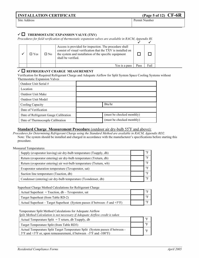
THERMOSTATIC EXPANSION VALVE (TXV)
Procedures for field verification of thermostatic expansion valves are available in RACM, Appendix RI.
Yes No
Access is provided for inspection. The procedure shall consist of visual verification that the TXV is installed on the system and installation of the specific equipment shall be verified.
Yes is a pass Pass Fail
REFRIGERANT CHARGE MEASUREMENT Verification for Required Refrigerant Charge and Adequate Airflow for Split System Space Cooling Systems without Thermostatic Expansion Valves
Outdoor Unit Serial # Location
Outdoor Unit Make
Outdoor Unit Model
Cooling Capacity Btu/hr
Date of Verification
Date of Refrigerant Gauge Calibration (must be checked monthly)
Date of Thermocouple Calibration (must be checked monthly) Standard Charge Measurement Procedure (outdoor air dry-bulb 55oF and above):
Procedures for Determining Refrigerant Charge using the Standard Method are available in RACM, Appendix RD2. Note: The system should be installed and charged in accordance with the manufacturer’s specifications before starting this procedure.
Measured Temperatures Supply (evaporator leaving) air dry-bulb temperature (Tsupply, db) oF
Return (evaporator entering) air dry-bulb temperature (Treturn, db) oF
Return (evaporator entering) air wet-bulb temperature (Treturn, wb) oF
Evaporator saturation temperature (Tevaporator, sat) oF
Suction line temperature (Tsuction, db) oF
Condenser (entering) air dry-bulb temperature (Tcondenser, db) oF
Superheat Charge Method Calculations for Refrigerant Charge Actual Superheat = Tsuction, db – Tevaporator, sat oF
Target Superheat (from Table RD-2) oF
Actual Superheat – Target Superheat (System passes if between -5 and +5°F) oF
Temperature Split Method Calculations for Adequate Airflow Split Method Calculation is not necessary if Adequate Airflow credit is taken
Actual Temperature Split = T return, db Tsupply, db oF
Target Temperature Split (from Table RD3) oF Actual Temperature Split Target Temperature Split (System passes if between -3°F and +3°F or, upon remeasurement, if between -3°F and -100°F)
oF
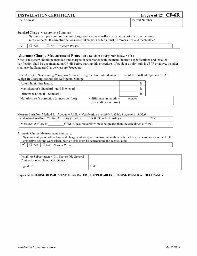
Residential Compliance Forms April 2005
INSTALLATION CERTIFICATE (Page 6 of 12) CF-6R Site Address Permit Number
Standard Charge Measurement Summary:
System shall pass both refrigerant charge and adequate airflow calculation criteria from the same measurements. If corrective actions were taken, both criteria must be remeasured and recalculated.
Yes No System Passes
Alternate Charge Measurement Procedure (outdoor air dry-bulb below 55 oF) Note: The system should be installed and charged in accordance with the manufacturer’s specifications and installer verification shall be documented on CF-6R before starting this procedure. If outdoor air dry-bulb is 55 oF or above, installer shall use the Standard Charge Measure Procedure: Procedures for Determining Refrigerant Charge using the Alternate Method are available in RACM, Appendix RD3. Weigh-In Charging Method for Refrigerant Charge
Actual liquid line length: ft
Manufacturer’s Standard liquid line length: ft
Difference (Actual – Standard): ft Manufacturer’s correction (ounces per foot) ______x difference in length =_____ounces
(+ = add) (- = remove)
Measured Airflow Method for Adequate Airflow Verification available in RACM, Appendix RD2.6
Calculated Airflow: Cooling Capacity (Btu/hr)______ X 0.033 (cfm/Btu-hr) = ________________ CFM
Measured Airflow is __________CFM (Measured airflow must be greater than the calculated airflow).
Alternate Charge Measurement Summary:
System shall pass both refrigerant charge and adequate airflow calculation criteria from the same measurements. If corrective actions were taken, both criteria must be remeasured and recalculated.
Yes No System Passes
Installing Subcontractor (Co. Name) OR General Contractor (Co. Name) OR Owner
Signature: Date: Copies to: BUILDING DEPARTMENT, HERS RATER (IF APPLICABLE) BUILDING OWNER AT OCCUPANCY
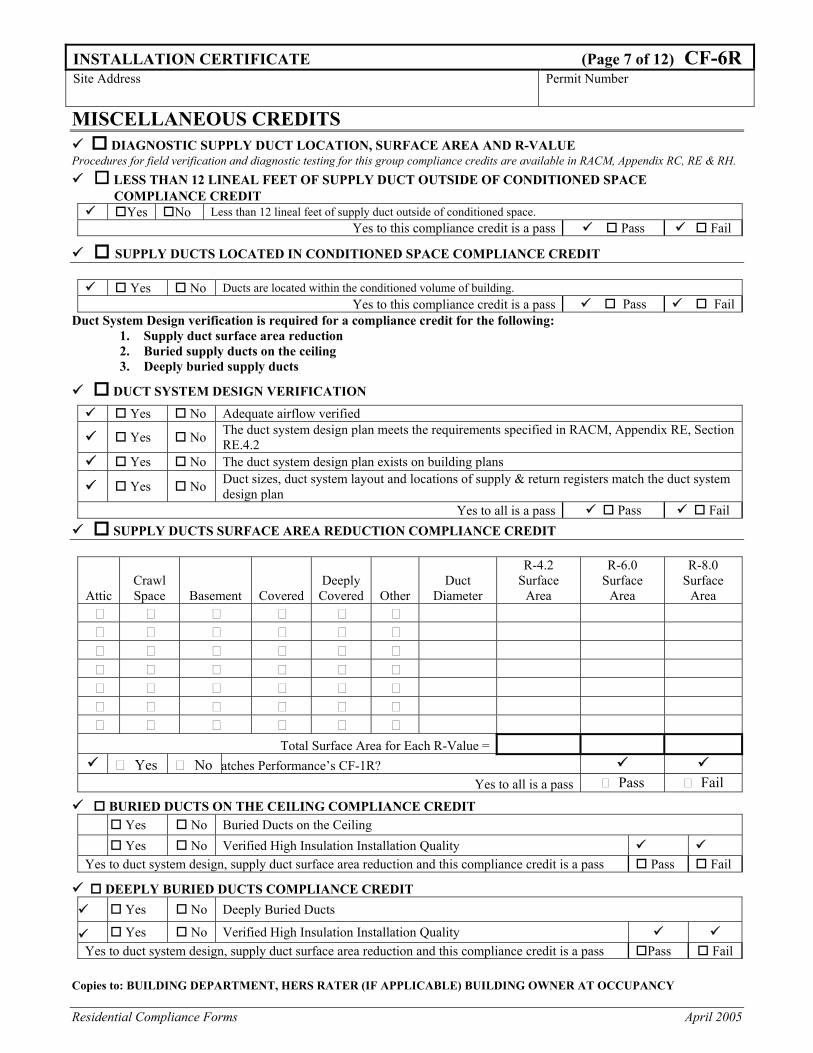
Residential Compliance Forms April 2005
INSTALLATION CERTIFICATE (Page 7 of 12) CF-6R Site Address Permit Number
MISCELLANEOUS CREDITS DIAGNOSTIC SUPPLY DUCT LOCATION, SURFACE AREA AND R-VALUE
Procedures for field verification and diagnostic testing for this group compliance credits are available in RACM, Appendix RC, RE & RH. LESS THAN 12 LINEAL FEET OF SUPPLY DUCT OUTSIDE OF CONDITIONED SPACE
COMPLIANCE CREDIT Yes No Less than 12 lineal feet of supply duct outside of conditioned space.
Yes to this compliance credit is a pass Pass Fail SUPPLY DUCTS LOCATED IN CONDITIONED SPACE COMPLIANCE CREDIT
Yes No Ducts are located within the conditioned volume of building.
Yes to this compliance credit is a pass Pass Fail Duct System Design verification is required for a compliance credit for the following:
1. Supply duct surface area reduction 2. Buried supply ducts on the ceiling 3. Deeply buried supply ducts
DUCT SYSTEM DESIGN VERIFICATION Yes No Adequate airflow verified
Yes No The duct system design plan meets the requirements specified in RACM, Appendix RE, Section RE.4.2
Yes No The duct system design plan exists on building plans
Yes No Duct sizes, duct system layout and locations of supply & return registers match the duct system design plan
Yes to all is a pass Pass Fail SUPPLY DUCTS SURFACE AREA REDUCTION COMPLIANCE CREDIT
Attic Crawl Space Basement Covered
Deeply Covered Other
Duct Diameter
R-4.2 Surface
Area
R-6.0 Surface
Area
R-8.0 Surface
Area
Total Surface Area for Each R-Value = Yes No atches Performance’s CF-1R?
Yes to all is a pass Pass Fail
BURIED DUCTS ON THE CEILING COMPLIANCE CREDIT Yes No Buried Ducts on the Ceiling Yes No Verified High Insulation Installation Quality
Yes to duct system design, supply duct surface area reduction and this compliance credit is a pass Pass Fail
DEEPLY BURIED DUCTS COMPLIANCE CREDIT Yes No Deeply Buried Ducts
Yes No Verified High Insulation Installation Quality Yes to duct system design, supply duct surface area reduction and this compliance credit is a pass Pass Fail
Copies to: BUILDING DEPARTMENT, HERS RATER (IF APPLICABLE) BUILDING OWNER AT OCCUPANCY
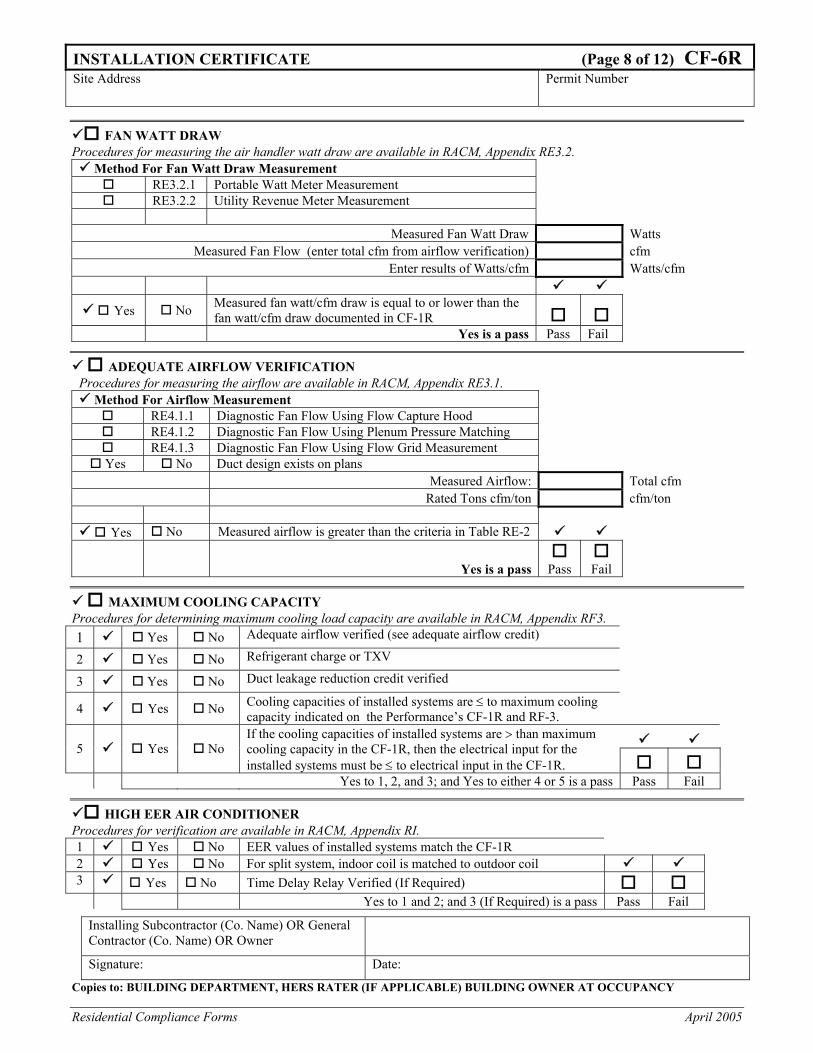
Residential Compliance Forms April 2005
INSTALLATION CERTIFICATE (Page 8 of 12) CF-6R Site Address Permit Number
FAN WATT DRAW Procedures for measuring the air handler watt draw are available in RACM, Appendix RE3.2.
Method For Fan Watt Draw Measurement RE3.2.1 Portable Watt Meter Measurement RE3.2.2 Utility Revenue Meter Measurement
Measured Fan Watt Draw Watts
Measured Fan Flow (enter total cfm from airflow verification) cfm Enter results of Watts/cfm Watts/cfm
Yes No Measured fan watt/cfm draw is equal to or lower than the fan watt/cfm draw documented in CF-1R
Yes is a pass Pass Fail
ADEQUATE AIRFLOW VERIFICATION Procedures for measuring the airflow are available in RACM, Appendix RE3.1.
Method For Airflow Measurement RE4.1.1 Diagnostic Fan Flow Using Flow Capture Hood RE4.1.2 Diagnostic Fan Flow Using Plenum Pressure Matching RE4.1.3 Diagnostic Fan Flow Using Flow Grid Measurement
Yes No Duct design exists on plans Measured Airflow: Total cfm Rated Tons cfm/ton cfm/ton
Yes No Measured airflow is greater than the criteria in Table RE-2
Yes is a pass
Pass
Fail
MAXIMUM COOLING CAPACITY Procedures for determining maximum cooling load capacity are available in RACM, Appendix RF3. 1 Yes No Adequate airflow verified (see adequate airflow credit) 2 Yes No Refrigerant charge or TXV 3 Yes No Duct leakage reduction credit verified 4 Yes No Cooling capacities of installed systems are ≤ to maximum cooling
capacity indicated on the Performance’s CF-1R and RF-3. 5 Yes No
If the cooling capacities of installed systems are > than maximum cooling capacity in the CF-1R, then the electrical input for the installed systems must be ≤ to electrical input in the CF-1R.
Yes to 1, 2, and 3; and Yes to either 4 or 5 is a pass Pass Fail
HIGH EER AIR CONDITIONER Procedures for verification are available in RACM, Appendix RI. 1 Yes No EER values of installed systems match the CF-1R 2 Yes No For split system, indoor coil is matched to outdoor coil 3 Yes No Time Delay Relay Verified (If Required)
Yes to 1 and 2; and 3 (If Required) is a pass Pass Fail
Installing Subcontractor (Co. Name) OR General Contractor (Co. Name) OR Owner
Signature: Date: Copies to: BUILDING DEPARTMENT, HERS RATER (IF APPLICABLE) BUILDING OWNER AT OCCUPANCY
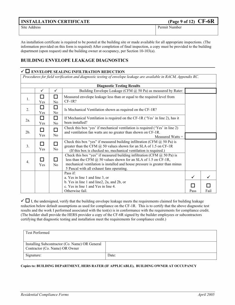
Residential Compliance Forms April 2005
INSTALLATION CERTIFICATE (Page 9 of 12) CF-6R Site Address Permit Number
An installation certificate is required to be posted at the building site or made available for all appropriate inspections. (The information provided on this form is required) After completion of final inspection, a copy must be provided to the building department (upon request) and the building owner at occupancy, per Section 10-103(a). BUILDING ENVELOPE LEAKAGE DIAGNOSTICS
ENVELOPE SEALING INFILTRATION REDUCTION Procedures for field verification and diagnostic testing of envelope leakage are available in RACM, Appendix RC.
Diagnostic Testing Results
Building Envelope Leakage (CFM @ 50 Pa) as measured by Rater:
1. Yes
No
Measured envelope leakage less than or equal to the required level from CF-1R?
2. Yes
No
Is Mechanical Ventilation shown as required on the CF-1R?
2a. Yes
No
If Mechanical Ventilation is required on the CF-1R (‘Yes’ in line 2), has it been installed?
2b. Yes
No
Check this box ‘yes’ if mechanical ventilation is required (‘Yes’ in line 2) and ventilation fan watts are no greater than shown on CF-1R.
Measured Watts =
3. Yes
No
Check this box “yes” if measured building infiltration (CFM @ 50 Pa) is greater than the CFM @ 50 values shown for an SLA of 1.5 on CF-1R
(If this box is checked no, mechanical ventilation is required.)
4. Yes
No
Check this box “yes” if measured building infiltration (CFM @ 50 Pa) is less than the CFM @ 50 values shown for an SLA of 1.5 on CF-1R, mechanical ventilation is installed and house pressure is greater than minus 5 Pascal with all exhaust fans operating.
Pass if:
a. Yes in line 1 and line 3, or b. Yes in line 1 and line2, 2a, and 2b, or c. Yes in line 1 and Yes in line 4. Otherwise fail.
Pass
Fail
I, the undersigned, verify that the building envelope leakage meets the requirements claimed for building leakage
reduction below default assumptions as used for compliance on the CF-1R. This is to certify that the above diagnostic test results and the work I performed associated with the test(s) is in conformance with the requirements for compliance credit. (The builder shall provide the HERS provider a copy of the CF-6R signed by the builder employees or subcontractors certifying that diagnostic testing and installation meet the requirements for compliance credit.)
Test Performed
Installing Subcontractor (Co. Name) OR General Contractor (Co. Name) OR Owner
Signature: Date: Copies to: BUILDING DEPARTMENT, HERS RATER (IF APPLICABLE), BUILDING OWNER AT OCCUPANCY
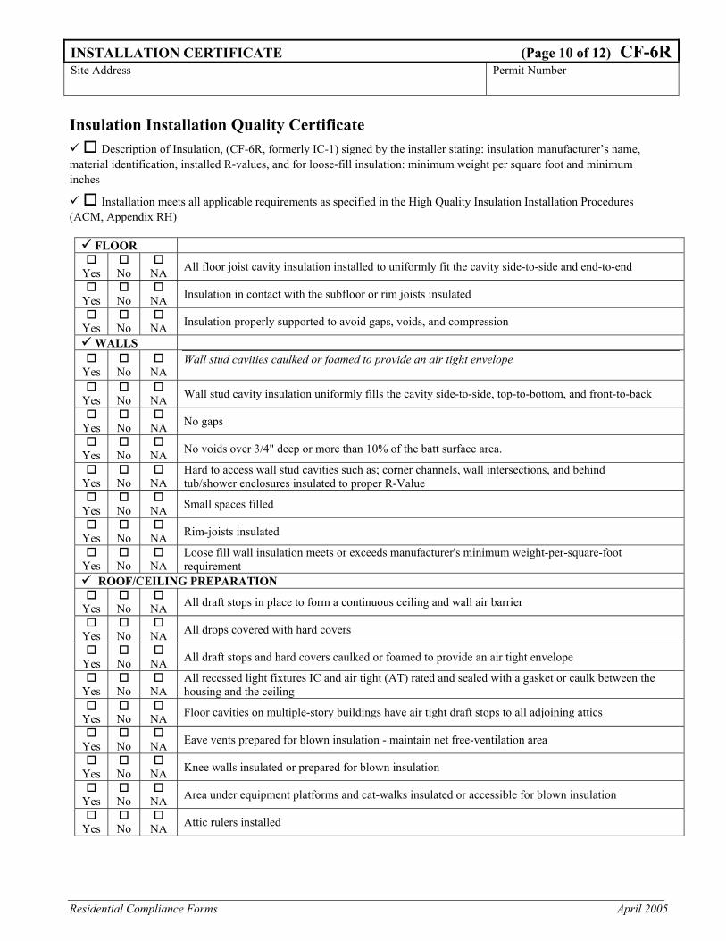
Residential Compliance Forms April 2005
INSTALLATION CERTIFICATE (Page 10 of 12) CF-6RSite Address Permit Number
Insulation Installation Quality Certificate
Description of Insulation, (CF-6R, formerly IC-1) signed by the installer stating: insulation manufacturer’s name, material identification, installed R-values, and for loose-fill insulation: minimum weight per square foot and minimum inches
Installation meets all applicable requirements as specified in the High Quality Insulation Installation Procedures (ACM, Appendix RH)
FLOOR
Yes
No
NA All floor joist cavity insulation installed to uniformly fit the cavity side-to-side and end-to-end
Yes
No
NA Insulation in contact with the subfloor or rim joists insulated
Yes
No
NA Insulation properly supported to avoid gaps, voids, and compression
WALLS
Yes
No
NA Wall stud cavities caulked or foamed to provide an air tight envelope
Yes
No
NA Wall stud cavity insulation uniformly fills the cavity side-to-side, top-to-bottom, and front-to-back
Yes
No
NA No gaps
Yes
No
NA No voids over 3/4" deep or more than 10% of the batt surface area.
Yes
No
NA
Hard to access wall stud cavities such as; corner channels, wall intersections, and behind tub/shower enclosures insulated to proper R-Value
Yes
No
NA Small spaces filled
Yes
No
NA Rim-joists insulated
Yes
No
NA
Loose fill wall insulation meets or exceeds manufacturer's minimum weight-per-square-foot requirement
ROOF/CEILING PREPARATION
Yes
No
NA All draft stops in place to form a continuous ceiling and wall air barrier
Yes
No
NA All drops covered with hard covers
Yes
No
NA All draft stops and hard covers caulked or foamed to provide an air tight envelope
Yes
No
NA
All recessed light fixtures IC and air tight (AT) rated and sealed with a gasket or caulk between the housing and the ceiling
Yes
No
NA Floor cavities on multiple-story buildings have air tight draft stops to all adjoining attics
Yes
No
NA Eave vents prepared for blown insulation - maintain net free-ventilation area
Yes
No
NA Knee walls insulated or prepared for blown insulation
Yes
No
NA Area under equipment platforms and cat-walks insulated or accessible for blown insulation
Yes
No
NA Attic rulers installed
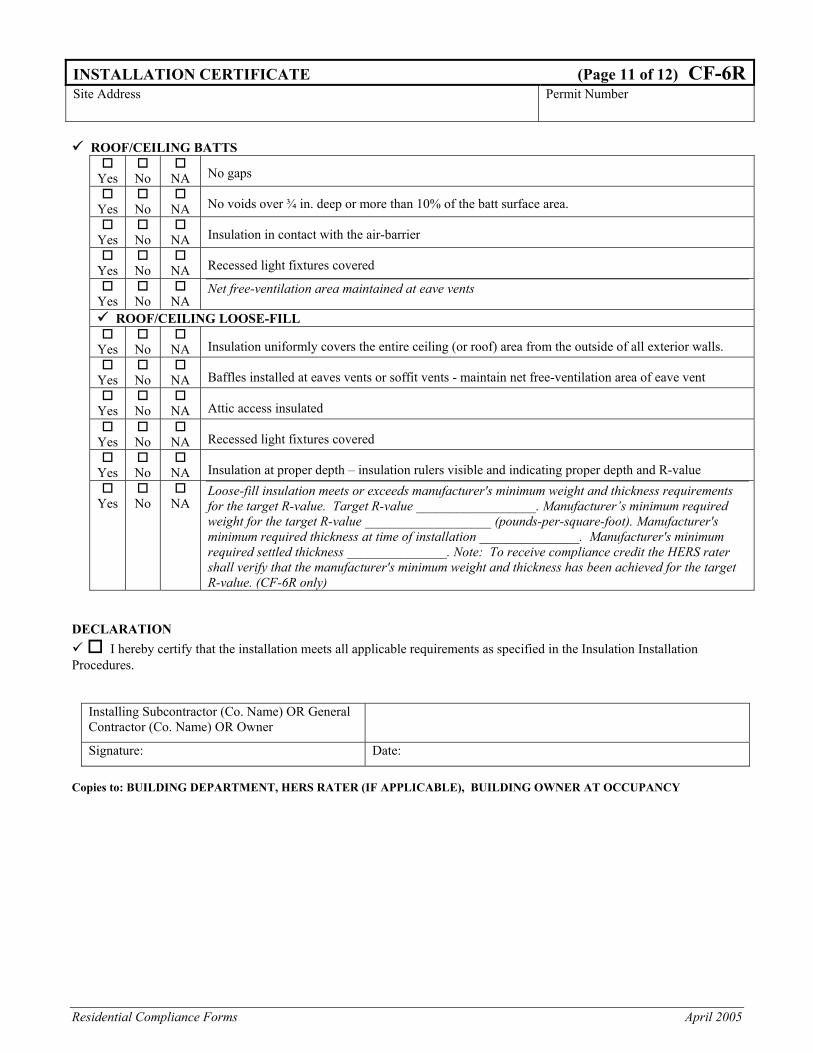
Residential Compliance Forms April 2005
INSTALLATION CERTIFICATE (Page 11 of 12) CF-6RSite Address Permit Number
ROOF/CEILING BATTS
Yes
No
NA No gaps
Yes
No
NA No voids over ¾ in. deep or more than 10% of the batt surface area.
Yes
No
NA Insulation in contact with the air-barrier
Yes
No
NA Recessed light fixtures covered
Yes
No
NA
Net free-ventilation area maintained at eave vents
ROOF/CEILING LOOSE-FILL
Yes
No
NA Insulation uniformly covers the entire ceiling (or roof) area from the outside of all exterior walls.
Yes
No
NA Baffles installed at eaves vents or soffit vents - maintain net free-ventilation area of eave vent
Yes
No
NA Attic access insulated
Yes
No
NA Recessed light fixtures covered
Yes
No
NA Insulation at proper depth – insulation rulers visible and indicating proper depth and R-value
Yes
No
NA Loose-fill insulation meets or exceeds manufacturer's minimum weight and thickness requirements for the target R-value. Target R-value __________________. Manufacturer’s minimum required weight for the target R-value ___________________ (pounds-per-square-foot). Manufacturer's minimum required thickness at time of installation _______________. Manufacturer's minimum required settled thickness _______________. Note: To receive compliance credit the HERS rater shall verify that the manufacturer's minimum weight and thickness has been achieved for the target R-value. (CF-6R only)
DECLARATION
I hereby certify that the installation meets all applicable requirements as specified in the Insulation Installation Procedures.
Installing Subcontractor (Co. Name) OR General Contractor (Co. Name) OR Owner
Signature: Date: Copies to: BUILDING DEPARTMENT, HERS RATER (IF APPLICABLE), BUILDING OWNER AT OCCUPANCY
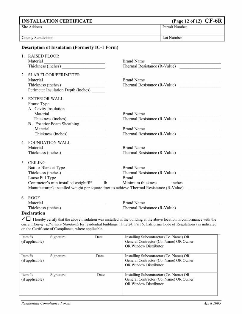
Residential Compliance Forms April 2005
INSTALLATION CERTIFICATE (Page 12 of 12) CF-6RSite Address Permit Number
County Subdivision Lot Number Description of Insulation (Formerly IC-1 Form) 1. RAISED FLOOR Material ____________________________ Brand Name ________________________________ Thickness (inches) ____________________ Thermal Resistance (R-Value) ___________________ 2. SLAB FLOOR/PERIMETER Material ____________________________ Brand Name ________________________________ Thickness (inches) ____________________ Thermal Resistance (R-Value) ___________________ Perimeter Insulation Depth (inches) ______ 3. EXTERIOR WALL Frame Type _________________________ A. Cavity Insulation Material _________________________ Brand Name ________________________________ Thickness (inches) _________________ Thermal Resistance (R-Value) ___________________ B . Exterior Foam Sheathing Material _________________________ Brand Name ________________________________ Thickness (inches) _________________ Thermal Resistance (R-Value) ___________________ 4. FOUNDATION WALL Material ____________________________ Brand Name ________________________________ Thickness (inches) ____________________ Thermal Resistance (R-Value) ___________________ 5. CEILING Batt or Blanket Type __________________ Brand Name ________________________________ Thickness (inches) ____________________ Thermal Resistance (R-Value) ___________________ Loose Fill Type ______________________ Brand _____________________________________ Contractor’s min installed weight/ft² _____lb Minimum thickness ______inches Manufacturer's installed weight per square foot to achieve Thermal Resistance (R-Value) _______________ 6. ROOF Material ___________________________ Brand Name ________________________________ Thickness (inches) ____________________ Thermal Resistance (R-Value) ___________________ Declaration
I hereby certify that the above insulation was installed in the building at the above location in conformance with the current Energy Efficiency Standards for residential buildings (Title 24, Part 6, California Code of Regulations) as indicated on the Certificate of Compliance, where applicable. Item #s (if applicable)
Signature Date Installing Subcontractor (Co. Name) OR General Contractor (Co. Name) OR Owner OR Window Distributor
Item #s (if applicable)
Signature Date Installing Subcontractor (Co. Name) OR General Contractor (Co. Name) OR Owner OR Window Distributor
Item #s (if applicable)
Signature Date Installing Subcontractor (Co. Name) OR General Contractor (Co. Name) OR Owner OR Window Distributor

Residential Compliance Forms April 2005