Embed Size (px)
Citation preview

Appendix 5
Wastewater Treatment Report/WaterFacilities Report


KEANE COPPELMAN ENGINEERS, P.C.CIVIL & ENVIRONMENTAL CONSULTANTS
113 SMITH AVENUE - MOUNT KISCO, NEW YORK 10549 (914) 241 [email protected]! fax:(914)241-6787
WASTEWATER FACILITIES REPORT
HIGHGATE / WOODLANDS DEVELOPMENT
REED ROAD
TOWN OF NORTH SALEM
WESTCHESTER COUNTY, NEW YORK
MAY 1, 2004
REV. JULY 12, 2004
REV. AUGUST 12, 2004
REV. OCTOBER 15, 2005
REV. MAY 7, 2010

KEANE COPPELMAN ENGINEERS, P.C.CIVIL & ENVIRONMENTAL CONSULTANTS
113 SMITH AVENUE - MOUNT KISCO, NEW YORK 10549 (914) 241 [email protected] fax: (914) 241-6787
A. DESCRIPTION OF PROPOSED DEVELOPMENT
The applicant, Joflo of North Salem Inc., proposes to
construct a housing development of 42 single family homes
and 76 senior age designed multi-family residences, both of
which will require the construction of a sewage treatment
plant to treat the sewage generated. The development will
occur on a vacant parcel of land bounded by Reed Road on the
east, the Town of Southeast to the west and Sun Valley Drive
to the south. Road access will occur from Reed Road with a
cross slope private road running from north to south. Reed
Road is a Town Road that has access to Hardscrabble Road on
the south. The current owner of the land is Joflo of North
Salem Inc., and the corporation and/or its successors in
interest will be responsible for the construction and
operation of the sewage treatment facility.

KEANE COPPELMAN ENGINEERS, P.C,CIVIL & ENVIRONMENTAL CONSULTANTS
113 SMITH AVENUE-MOUNT KISCO, NEW YORK 10549 (914) [email protected] fax:(914)241-6787
B. REQUIRED APPROVALS
Joflo of North Salem Inc. will apply for a New York State
SPDES permit from the New York State Department of
Environmental Conservation and also secure approval for the
facility from the New York City Department of Environmental
Protection (NYCDEP). This SPDES permit will contain
specified parameters with regard to quantity and quality of
effluent flow which is discharged. The plant will be
operated in conformance with the permit requirement; this
would include routine testing according to a specified
schedule, with monthly reporting to the requisite government
agencies.
With respect to the design of the sewage treatment
facilities, the Westchester Department of Health and NYCDEP
play an active role in reviewing the design. Each agency
will review the wastewater facility report and the detailed
design drawings and approve same. The review will
include an analysis of the capabilities of the proposed
sewage treatment plant and the construction details to
ensure the plant will yield a quality effluent product.

KEANE COPPELMAN ENGINEERS, P.C.CIVIL & ENVIRONMENTAL CONSULTANTS
113 SMiTH AVENUE - MOUNT KISCO, NEW YORK 10549 (914} 241 -2235info@keanecoppe)(nan.com fax: (914) 241-6787
C. HYDROLOGY
The property contains two intermittent streams and one
perennial stream. Intermittent stream one runs South to
North in the Midwestern portion of property. Intermittent
stream two runs North to South toward pond. The perennial
stream runs from west to East in the front of the property.
As noted above, there will be a subsurface discharge to
subsurface sewage disposal fields which will not adversely
affect the quality of surface waters.
D. OPERATOR
The waste water treatment facilities must be operated by a
licensed New York State Sewage Treatment Plant Operator.
The Operator will be responsible for routine maintenance of
all mechanical equipment and monitoring of the treatment
plant processes. An independent laboratory will be under
contract to provide monthly testing data to insure the plant
is in compliance with the effluent parameters specified in
the SPDES permit.

KEANE COPPELMAN ENGINEERS, P.C.CIVIL & ENVIRONMENTAL CONSULTANTS
113 SMITH AVENUE-MOUNT KISCO, NEW YORK 10549 (914) [email protected] fax: (914) 241 -6787
E. DESCRIPTION OF TREATMENT PROCESS UNITS
1. PRIMARY SETTLING
Primary settling tank(s) will be installed at the influent
end of the plant. The purpose of the primary settling
process is to allow the solids in the sewage effluent to
settle via gravity to the bottom of the tank. Reinforced
concrete tanks will be sized in sufficient volume to allow a
detention period in conformance with all pertinent
regulations. There will be additional volume for the
storage of sludge. Sludge will be removed from the site and
processed by an approved facility.
2. ROTATING BIOLOGICAL CONTACTOR
Rotating biological contactors will be utilized in order to
achieve sufficient biological oxygen demand reduction and
ammonia nitrogen removal. The disc will be placed in a
reinforced concrete compartmentalized tank. A building will
be constructed over the disc and heated to maintain a
consistent 55 degrees Fahrenheit temperature in all weather
conditions. The reason for the application of heat is that
the degree of biological treatment diminishes severely when
the temperature falls below 50 degrees Fahrenheit.

KEANE COPPELMAN ENGINEERS, P.C.CIVIL & ENVIRONMENTAL CONSULTANTS
113 SMITH AVENUE - MOUNT KISCO, NEW YORK 10549 (914) [email protected] fax: (914) 241 -6787
3. SECONDARY CLARIFIER
A solids contact clarifier will be utilized for secondary
treatment and liquid alum could be injected to a center
settling cone which will provide for the removal of
phosphorous. The settleable solids will be given the
opportunity to settle via gravity, with the sludge collected
at the bottom of the tank.
4. RAPID SAND FILTRATION
Depending on the permit requirements, dual rapid sand
filters will be utilized in order to provide tertiary
treatment (polishing) of the effluent. The filters will be
provided with automatic backwash capabilities, thus insuring
proper operation at all times.
5. DISINFECTION
Proper disinfection will occur by utilization of ultra
violet light. This process allows for a bacteria
inactivation without producing a harmful effluent parameter
such as chlorine residual.

KEANE COPPELMAN ENGINEERS, P.C.CIVIL & ENVIRONMENTAL CONSULTANTS
113 SMITH AVENUE - MOUNT KISCO, NEW YORK 10549 (914) 241 -2235infoekeanecoppelman.com fax: (914) 241 -6787
6. REAERATION
If required by the SPDES Permit, reaeration will occur in
order to provide a supply of dissolved oxygen in sufficient
quantity so that the aquatic life in the effluent will not
experience a lack of oxygen. Typically, a reinforced
concrete tank will be utilized with a diffuser pipe network,
introducing air which contains a sufficient input of oxygen
to reach a goal of 7 mg/1.
F. PLANT LOCATION
The location of the proposed sewage treatment is one of
primary concern. It should be situated at a reasonable
distance from any existing or proposed dwelling unit. Thus,
in effect, a buffer will be provided for odor control and
noise. It is for this reason that the treatment plant is
located as shown on the wastewater parcel (see attached site
plan.) in somewhat of the center of the property.
G. OWNERSHIP OF WASTEWATER FACILITIES
The waste water collection system and sewage treatment
facility will be owned and operated by the Sewage Works

KEANE COPPELMAN ENGINEERS, P.C.CIVIL & ENVIRONMENTAL CONSULTANTS
113 SMITH AVENUE - MOUNT! KISCO, NEW YORK 10549 (914) 241 [email protected] fax: (914) 241 -6787
Corporation as such the Town will not have any financial
involvement.
H. COLLECTION SYSTEM
A separate central sanitary sewer collection system will be
constructed to serve the project. The system will consist
of plastic sewer piping and pre-cast sewer manholes and
pumping stations. Generally, a maximum of 300 foot of sewer
main will be constructed between manholes. In addition,
manholes will be provided all changes or direction (vertical
and horizontal). A comprehensive testing program will be
implemented in order to ensure that no leakage will occur in
excess of Health Department guidelines prior to placing said
sewer in service.
H. FLOW IMPACT ON RECEIVING STREAM
Since this is pretreated subsurface discharge, there will be
no adverse impact to the receiving stream or wetland.

KEANE COPPELMAN ENGINEERS, P.C.CIVIL & ENVIRONMENTAL CONSULTANTS
113 SMITH AVENUE - MOUNT KiSCO, NBA/YORK 10549 (914) [email protected] fax:(914)241-6787
DESIGN CONSIDERATION
ADVANCED WASTEWATER TREATMENT PLANT
HIGHGATE / WOODLANDS PROJECT
TOWN OF NORTH SALEM
WESTCHESTER COUNTY, NEW YORK

KEANE COPPELMAN ENGINEERS, P.C.CIVIL & ENVIRONMENTAL CONSULTANTS
113 SMITH AVENUE - MOUNT KISCO, NEW YORK 10549 (914) 241 -2235info®keaneeoppelman,com fax: (914} 241 -6787
DESIGN PARAMETERS
SIZING OF TREATMENT UNITS
1. DESIGN FLOW
SINGLE FAMILY RESIDENCES
12-4BR HOMES, 2500 GSF @ 475 GPD
14-4BR HOMES, 3500 GSF @ 475 GPD
16, 5 BR HOMES, 4500 GSF @ 550 GPD
TOTAL PROJECTED FLOW
26 x 475 GPD/DWELLING = 12,350 GPD
16 x 550 GPD/DWELLING = 8,800 GPD
MULTI-FAMILY AGE RESTRICTED •• OVER 55 POPULATION
28-1BR CONDOMINIUMS, 2600 GSF @ 200 GPD
48-2BR CONDOMINIUMS, 3000 GSF @ 300 GPD
TOTAL PROJECTED FLOW
28 X 200 GPD/UNIT = 5600 GPD
48 x 300 GPD/UNIT = 14400 GPD
ALL FIXTURES WILL BE WATER SAVING TYPE-YIELDING A 20%
REDUCTION IN FLOW THEREFORE, THE PROJECT FLOW WILL BE:
(21,150 GPD + 20,000 GPD)(0.80)= 32,920 GPD

KEANE COPPELMAN ENGINEERS, P.C.CIVIL & ENVIRONMENTAL CONSULTANTS
113 SMFTH AVENUE - MOUNT KISCO, NEW YORK 10549 (914) 241 -2235info@keanecoppelman,com fax: (914) 241-6787
FLOW CALCULATION
FOR THE PURPOSES OF DESIGN, ASSUME 33,000 GPD
AVERAGE DAILY FLOW = 33,000 GALLONS PER DAY = 23 GPM
AVERAGE HOURLY FLOW = 49,500 GALLONS PER DAY = 34 GPM
PEAK HOURLY FLOW = 123,750 GALLONS PER DAY = 86 GPM
2. RAW SEWAGE TREATMENT
BOD 5 = 200 mg/1
SS = 200 mg/1
NH 3 = 2 5 mg/1
P = 4 mg/1
0 2 = 0 mg/1
The above parameters have been used when designing waste
water treatment facilities in the area. In actual plant
operations, the raw strengths noted above are seldom
experienced. This yields a very conservative design
approach.
10

KEANE COPPELMAN ENGINEERS, P.C. '"*r
CIVIL & ENVIRONMENTAL CONSULTANTS
113 SMfTH AVENUE - MOUNT KISCO, NEW YORK 10549 (914) 241 [email protected] fax: (914) 241-6787
3. PROJECTED EFFLUENT LIMITATIONS
(assuming no credit for subsurface discharge)
BOD 5 =5.0 mg/1 PH= 6.5 TO 7.5
SS =10.0 FECAL COLI = .200
NH 3 =2.0 mg/1 CHLORINE RESIDUAL =0.05 mg/1
P =1.0 mg/1 SETTLE SOLIDS =0.10 mg/1
4. SIZING OF PROCESS UNITS
The following calculations provide for the proper treatment
of the wastewater that will be generated.
A. PRIMARY SETTLING
UTILIZE SEPTIC TANKS FOR PRIMARY SETTLING. DESIGN FOR
DAILY FLOW PLUS STORAGE. USE 33,000 GALLON PROCESS
FLOW + 8,000 SLUDGE TOTAL CAPACITY = 41,000 GALLONS.
TOTAL CAPACITY = 4 x 12,000 =48,000 GALLON > 41,000 GAL
B. EQUALIZATION
EQUALIZE THE FLOW FOR 24 HOUR DELIVERY. UTILIZE 12,000
GALLON PUMP PIT WITH 25 GPM PUMPS.
C. ROTATING BIOLOGICAL CONTACTOR
SIZE FOR 33,000 GPD FOLLOWING SEPTIC TANK SEDIMENTATION.
AERATE THE FIRST DISC CHAMBER TO PROVIDE AEROBIC
11

KEANE COPPELMAN ENGINEERS, P.C.CIVIL & ENVIRONMENTAL CONSULTANTS
113 SMITH AVENUE - MOUNT KiSCO, NEW YORK 10549 (914) 241 [email protected] fax: (914) 241-6787
ENVIRONMENT AFTER ANAEROBIC SEPTIC TANK ENVIRONMENT.
TEMPERATURE CORRECTION =1.0 (55 DEGREES F)
BOD LOADING =1.0 LB/1,000 SF/DAY
NITRIFICATION LOADING =0.32 LB/1,000 SF/DAY
SEPTIC TANK FACTOR =1.5
MIN. AREA = Q X WS X WC X TB X SI
AR
A BOS = 0.033 X 100 X 8.34 X 1.0 X 1.5
1
=41.3 KSF
A B15 = 0.033 X 100 X 8.34 X l.Q X 1.5
2
=20.6 KSF
AN = 0.033 X 25 X 8.34 X 1.0 X 1.5
0.32
= 32.25 KSF
ASTO = 0.033 X 100 X 1.0 X 1.5
2.5
=2.0 KSF
A REQD = 41.3 KSF + 20.6 KSF
= 62 KSF
USE CLOW MODEL F-77/88,000 SF EACH
12

KEANE COPPELMAN ENGINEERS, P.C.CIVIL & ENVIRONMENTAL CONSULTANTS
113 SMfTH AVENUE - MOUNT KISCO, NEW YORK 10549 {914) 241 [email protected] fax: (914} 241 -6787
D. SECONDARY SETTLING
SIZE FOR 600 GPD/SF & 3 HRS . DETENTION
33,000 GPD/600 = 55 SF REQD
USE A KEENE SOUNDS CONTACT CLARIFIER 10'x 10' = 100 SF
PROVIDE A CENTER SETTLING CONE FOR THE ADDITION OF
LIQUID ALUM TO PRECIPITATE PHOSPHOROUS.
ACTUAL LOADING - 33,000/120 = 275 GAL/SF
PROVIDE A SLUDGE RETURN PUMP WHICH WILL ALLOW
RECIRCULATION OR DISCHARGE TO THE HEAD OF THE PLANT OR
TO THE SLUDGE HOLDING TANK- OPERATOR MANUAL CONTROLLED.
E. SAND FILTRATION
RAPID SAND FILTRATION WILL BE PROVIDED AT A RATE OF 1.0
PPM/SF/AVG FLOW OR 3.0 GPM/SF @ peak.
23 GPM/1.0 = 24 SF
86 GPM/3.0 = 29 SF
USE TWO SAND FILTER UNITS EACH WITH A CAPACITY OF 25 SF
-EACH FILTER 5x5 COMPLETE WITH AUTOMATIC BACKWASH. (50
SF SUPPLIED)
13

KEANE COPPELMAN ENGINEERS, P.C.CIVIL & ENVIRONMENTAL CONSULTANTS
113 SMiTH AVENUE - MOUNT KiSCO, NEW YORK 10549 (914} 241 [email protected] fax: (914} 241 -6787
F. DISINFECTION
There is a limiting factor for the allowable level of
chlorine level in the effluent of the plant discharge.
Other methods of disinfection are considered such as
ozone or ultra-violet light. For ultra-violet, dual
units are required each with a capacity of treating
33,000 gpd = 23 gpm at an average daily flow. The
disinfection will follow rapid sand filtration. The
effluent quality should not a pose a problem as far as
clarity of the water being treated. The plant will use
two units manufactured by ultra-violet purification
systems.
For ultra-violet, dual units are required each with a
capacity of treating 33,000 gpd = 23 gpm at an average
daily flow. The disinfection will follow rapid sand
filtration. The effluent quality should not pose a
problem as far as clarity of the water being treated.
The plant will use two units manufactured by ultra-
violet purification systems.
14

KEANE COPPELMAN ENGINEERS, P.C.CIVIL & ENVIRONMENTAL CONSULTANTS
113 SMfTH AVENUE - MOUNT KISCO, NEW YORK 10549 (914) [email protected] fax: (914) 241-6787
G. POST AERATION
DESIGN 20 MINS. DETENTION @ AVG FLOW
23 X 48 = 1104 GALLONS - USE ONE 1200 GAL TANK
8' WIDE x 10' LONG x 10' DEEP = 6,000 GAL.
EXCESS CAPACITY PROVIDES FOR BACKWASH WATER FOR
THE RAPID SAND FILTERS.
DIFFUSED AIR REQD • DO 0 TO 7 mg/lD
4 # 02 = 60 #AIR/DAY = 700 CF/DAY
ASSUME 7% TRANSFER RATE = 27 CFM
H. SLUDGE STORAGE
THE SEPTIC TANKS ARE SIZED FOR 1 DAY FLOW AND
CONSEQUENTLY ARE SUFFICIENT IN SIZE TO ALLOW FOR PROPER
SLUDGE STORAGE.
15

KEANE COPPELMAN ENGINEERS, P.C.CIVIL & ENVIRONMENTAL CONSULTANTS
113 SMITH AVENUE - MOUNT KISCO. NEW YORK 10549 (914) 241 -2235irtfo@keana;oppelman.com fax: (914) 241-6787
I. PHOSPHOROUS REMOVAL
DESIGN 2 MOLES OF AL TO L MOLE P
P = 10 mg/1 P FINAL = lmg/1
REMOVAL = 9 mg/1 = 9 ppm
= 9 x 0.07 x 8.34
=5.25 #/DAY
ADD ALUM AT 20 TO 1
20 x 2.25 #/DAY= 45 #/DAY
The above outline indicates that the plant will be designed
and constructed in compliance with the government standards
for waste treatment works.
J. SUBSURFACE DISCHARGE LEACHING SYSTEM
Design Flow = 33,000 gpd
Using an Application Rate of 1.2 gpd per square foot
Assuming a 25% reduction in Required Leaching Area as aresult of Pre-Treatment, the Required Leaching Area
= 33,000 gpd / 1.2 gpd per sf x 0.75 = 20,625 sf
Using 4'-0" x 4'-0" Pre Cast Concrete Leaching Galley, withan effective width of 6'-0",Required Length of Galley System
= 20,625 sf / 8.67 sf of leaching area per lineal foot= 2,380 lineal feet of galley required for primary
System
Provide a reserve area of 50% as a result of Pre-Treatment= 1,190 lineal feet of galley within reserve area.
16

WATER FACILITIES REPORT
HIGHGATE-WOODLANDS DEVELOPMENT
REED ROAD
TOWN OF NORTH SALEM
WESTCHESTER COUNTY, NEW YORK
May 1, 2004 REV JULY 12, 2004
REV AUGUST 12, 2004 REV OCTOBER 15, 2005
REV MAY 7, 2010 REV December 27, 2012

Highgate-Woodlands Subdivision Water Facilities Report
Keane Coppelman Gregory Engineers, P.C. Page 1 of 6
A. DESCRIPTION OF PROPOSED DEVELOPMENT The applicant, Joflo of North Salem Inc., proposes to construct a housing development of forty two single family homes and seventy six senior age designed multi-family residences, both of which will require the construction of a sewage treatment plant to treat the sewage generated. The development will occur on a 160 acre vacant parcel of land bounded by Reed Road on the East, the Town of Southeast to the West and Sun Valley Drive to the South. Road access will occur from Reed Road with a cross slope private road running from South to North. Reed Road is a Town Road that has access from Hardscrabble Road on the south. The current owner of the land is Joflo of North Salem Inc., and the corporation and/or its successors in interest will be responsible for the construction and operation of the sewage treatment facility. B. REQUIRED APPROVALS Joflo of North Salem Inc. will apply for and a New York State Water Taking Permit from the New York State Department of Environmental Conservation and also secure approval for the facility from the Westchester County Department of Health as permitting agent for the New York State Dept. of Health. The permit will contain specified parameters with regard to quality of potable water that can be taken from the groundwater in New York State. The plant will be operated in conformance with the permit requirement; this would include routine testing according to a specified schedule, with monthly reporting to the requisite government agencies. With respect to the design of the water treatment facilities, the Westchester County Department of Health will play the most active roll in reviewing the design. The agency will review the water facility report and the detailed design drawings and approve same. C. HYDROLOGY The property contains two intermittent streams and one perennial stream. Intermittent stream one runs South to North in the Midwestern portion of property. Intermittent stream two runs North to South toward pond. The perennial stream runs from west to East in the front of the property. As noted above, there will be a subsurface discharge to subsurface sewage disposal fields which will not adversely affect the quality of surface waters. D. OPERATOR The water treatment facilities must be operated by a licensed New York State Water Treatment Plant Operator. The Operator will be responsible for routine maintenance of all mechanical equipment and monitoring of the treatment plant processes. An independent laboratory will be, under contract, to provide monthly testing data to insure the plant is in compliance with the effluent parameters specified in the Water permit. E. OWNERSHIP OF WATER FACILITIES The waste water collection system and sewage treatment facility will be owned and operated by a Water Works Corporation with no financial burden on the own.

Highgate-Woodlands Subdivision Water Facilities Report
Keane Coppelman Gregory Engineers, P.C. Page 2 of 6
DESIGN CONSIDERATIONS
WATER TREATMENT PLANT
HIGHGATE-WOODLANDS DEVELOPMENT
REED ROAD
TOWN OF NORTH SALEM
WESTCHESTER COUNTY, NEW YORK
Highgate-Woodlands Subdivision Water Facilities Report
Keane Coppelman Gregory Engineers, P.C. Page 3 of 6
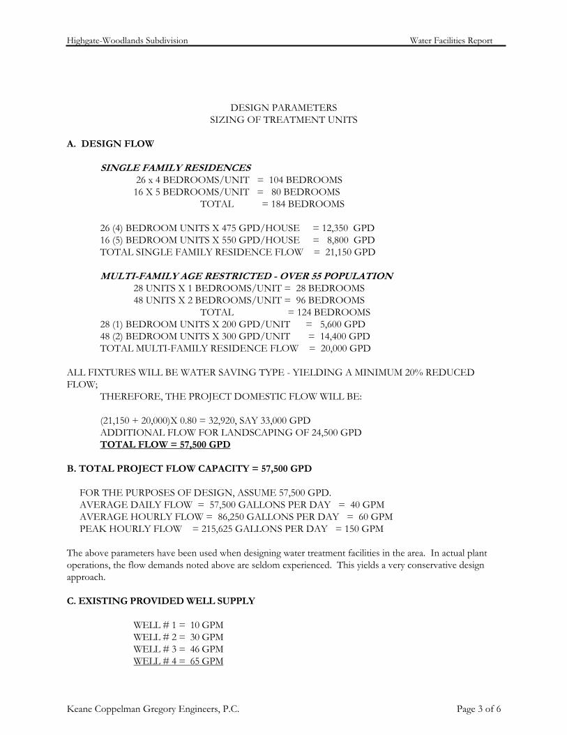
DESIGN PARAMETERS SIZING OF TREATMENT UNITS
A. DESIGN FLOW SINGLE FAMILY RESIDENCES 26 x 4 BEDROOMS/UNIT = 104 BEDROOMS 16 X 5 BEDROOMS/UNIT = 80 BEDROOMS TOTAL = 184 BEDROOMS 26 (4) BEDROOM UNITS X 475 GPD/HOUSE = 12,350 GPD 16 (5) BEDROOM UNITS X 550 GPD/HOUSE = 8,800 GPD TOTAL SINGLE FAMILY RESIDENCE FLOW = 21,150 GPD MULTI-FAMILY AGE RESTRICTED - OVER 55 POPULATION 28 UNITS X 1 BEDROOMS/UNIT = 28 BEDROOMS 48 UNITS X 2 BEDROOMS/UNIT = 96 BEDROOMS TOTAL = 124 BEDROOMS 28 (1) BEDROOM UNITS X 200 GPD/UNIT = 5,600 GPD 48 (2) BEDROOM UNITS X 300 GPD/UNIT = 14,400 GPD TOTAL MULTI-FAMILY RESIDENCE FLOW = 20,000 GPD ALL FIXTURES WILL BE WATER SAVING TYPE - YIELDING A MINIMUM 20% REDUCED FLOW;
THEREFORE, THE PROJECT DOMESTIC FLOW WILL BE: (21,150 + 20,000)X 0.80 = 32,920, SAY 33,000 GPD ADDITIONAL FLOW FOR LANDSCAPING OF 24,500 GPD TOTAL FLOW = 57,500 GPD
B. TOTAL PROJECT FLOW CAPACITY = 57,500 GPD FOR THE PURPOSES OF DESIGN, ASSUME 57,500 GPD. AVERAGE DAILY FLOW = 57,500 GALLONS PER DAY = 40 GPM AVERAGE HOURLY FLOW = 86,250 GALLONS PER DAY = 60 GPM PEAK HOURLY FLOW = 215,625 GALLONS PER DAY = 150 GPM The above parameters have been used when designing water treatment facilities in the area. In actual plant operations, the flow demands noted above are seldom experienced. This yields a very conservative design approach. C. EXISTING PROVIDED WELL SUPPLY WELL # 1 = 10 GPM WELL # 2 = 30 GPM WELL # 3 = 46 GPM WELL # 4 = 65 GPM

Highgate-Woodlands Subdivision Water Facilities Report
Keane Coppelman Gregory Engineers, P.C. Page 4 of 6
TOTAL = 151 GPM The system will be REQUIRED to provide two (2) times the average daily flow without considering the largest yielding well. Required supply = 40 gpm x 2 = 80 gpm Provided Supply = 10 gpm + 30 gpm + 46 gpm = 86 gpm 86 gpm is greater than 80 gpm; therefore ok D. SOURCE DEVELOPMENT (Refer to Well Logs By BOYD ARTISAN WELL COMPANY - ATTACHED). The existing wells will supply the required amount of water. The sum of the well yields equals, 10 + 30 + 46 +
65 = 151 gpm which is 3.75 times the average daily demand of 40 gpm. With respect to construction standards for the wells, applicable governing regulations dictate the methods of construction and, further, said specifications are incorporated into the design drawings. In addition, a significant testing program has been completed in conformance with New York State Regulation Sub Part 5. (See attached)
E. STORAGE REQUIREMENTS Subsurface constructed steel storage tank(s) will be provided sized for the quantity of 60,000 gallons, greater
than the average daily demand of 57,500 gallons. Two - 30,000 gallon steel storage tanks will be constructed on reinforced concrete cradles. Well discharge lines will enter a pump house, where the water will be chlorinated and discharged to the storage tank. Access for cleaning and inspection will be made via locked steel manhole ports placed above the ground surface. To prevent surface water from entering the tanks, grading will be provided in such a manner so as to direct water away from the tank.
F. BOOSTER PUMPS Dual alternating booster pumps will be provided in the pump house. Each pump will be designed to supply in
excess of ten times the average daily demand. Therefore, in the event that one of the pumps becomes inoperable, the remaining pump will be able to supply sufficient water. Pressure gauges will be supplied on the pump discharge line so that pump efficiency can be monitored.
Required Booster Pump Sizing = 40 gpm x 10 = 400 gpm G. DISINFECTION A chlorinator will be supplied capable of pumping 0-20 gpd vs. 100 psi. In addition, a duplicate unit will be
available in the event the initial chlorinator fails. Chlorine will be injected into the well lines prior to discharge into the storage tank for proper detention time.
SIZING CALCULATIONS: Well cycle yield = 100 GPM Running time = 60,000 / 100 = 600 MINUTES ASSUME 0.5 mg/l Concentration
For 100 gpm @ 1.5 ppm = 0.00016 gal chlorine straight (max needs) 2.5% solution = 0.00128 gal/min of 12.5 % solution
with a 10 to 1 dilution = = 0.00128/ 0.1 = .0128 gpd of diluted

Highgate-Woodlands Subdivision Water Facilities Report
Keane Coppelman Gregory Engineers, P.C. Page 5 of 6
H. METERING Each well will have its own 1-1/2" diameter water meter. This will allow the operator the capability of
determining the output of each well. In addition, a control panel will be utilized which will give continuous read-out of the following:
1. STATIC WELL LEVEL 2. WATER PRESSURE 3. AIR PRESSURE 4. HAND, AUTOMATIC, AND OFF POSITIONS FOR ALL PUMPS 5. STORAGE TANK WATER LEVEL 6. NO FLOW CUT OUT FOR ALL PUMPS I. EMERGENCY POWER An emergency generator, complete with automatic transfer switch, will be housed in the water pump house. The generator will be sized to operate all submersible well pumps, booster pumps, chlorinator facilities, and lighting. Therefore, service will be insured in the event of power outage. The exhaust from the generator will exit the building through the roof and sufficient ventilation louvers will be provided so that the propane engine can operate efficiently. J. HEATING AND VENTILATION Space heaters will be provided, in order to maintain a 50 degree Fahrenheit temperature, assuming 0 degrees Fahrenheit outside. In addition to the aforementioned louvers, an electrical exhaust fan will be provided adjacent to the chlorination facilities. K. DISTRIBUTION SYSTEM A central water main distribution system will be installed to serve the development. Significant design features will include:
1. PUSH JOINT PVC DISTRIBUTION PIPING 2. CONCRETE THRUST BLOCKS AT ALL BENDS 3. “LOOPING" OF MAINS WHENEVER FEASIBLE 4. ISOLATION VALVES FOR MAINTENANCE 5. BLOW OFFS HYDRANTS AT DEAD END LOCATIONS 6. VALVE BOXES TO GRADE FOR ALL VALVES 7. PRESSURE TESTING OF ALL MAINS 8. DISINFECTION OF ALL MAINS

Highgate-Woodlands Subdivision Water Facilities Report
Keane Coppelman Gregory Engineers, P.C. Page 6 of 6
L. WATER PLANT LOCATION The water treatment plant will be located at the higher elevations of the site (the western portion) within the
proposed site development area. This will benefit the system's capability of being disconnected in the event that a municipal supply becomes available or if the town asks the applicant to become part of the Croton Falls Public Water Supply. The pump house equipment will be designed to give 35 psi pressure at the maximum dwelling elevation.
M. OWNERSHIP OF THE WATER SYSTEM The system which consists of the wells, the water pump house, and the distribution mains will be owned and
operated by a Private Transportation Corporation. Said corporation will be formed under the laws of the State of New York. With private ownership, no burden will be added to the municipal services of the Town.
N. COMPLIANCE WITH PERMIT STANDARDS The facilities outlined above will be constructed in full compliance with all applicable governing standards and
they will be operated in compliance with all operational standards including regular testing and monitoring as described in public health laws.
O. EMERGENCY POWER OPERATIONS PROVISIONS 1) MULTIPLE WELLS RUNNING 2) DUAL BOOSTER PUMPS RUNNING 3) DUAL STORAGE TANKS MAINTAINING PROPER LEVEL 4) AIR COMPRESSORS 6) CONTROL & ALARM PANELS 7) AUTOMATIC TRANSFER SWITCH


![Final Major Project - Highgate Cemetery [Brief]](https://img.pdfslide.us/doc/110x75/568c4d071a28ab4916a267f8/final-major-project-highgate-cemetery-brief.jpg)