Embed Size (px)
Citation preview

Appendix I -1
Appendix I: SESC Best Management Practices Guidance Sheets
Introduction Best Management Practices (BMP): BMPs are any structural, vegetative or managerial practice used to treat, prevent or reduce water pollution.
The following BMPs include guidance which will provide the user with information to help design and implement the BMP. This is an important concept, in that: 1) no BMP can be used at every site; and 2) no BMP can include so many specifications that all possible uses and all possible conditions are included. Each site must be evaluated, and specific BMPs can be selected which will perform under the site conditions.
The SESC BMPs found in this manual were developed for use in Michigan. BMPs developed for other states may not necessarily work in Michigan. For example, vegetative BMPs should emphasize the use of grasses which have adapted to Michigan. Vegetation which has adapted to Michigan is not necessarily going to adapt to other states. We acknowledge that this set of BMPs is not all-inclusive. There are many additional BMPs that can be found in the Michigan Department of Environmental Quality (DEQ) Guidebook of Best Management Practices for Michigan Watersheds, hereafter referred to at the BMP Guidebook. Additionally, specifications for individual SESC products can be found at SESC retailers and on supplier websites. Several of the BMPs listed here include companion and alternative BMPs which are not included in the training manual, but are included in the BMP Guidebook. In these cases, the page number where the BMP can be found in the BMP Guidebook is provided.
We encourage creativity and innovation, but provide potential users with this list of SESC BMPs because they have been proven to work when designed, installed and maintained correctly, and are some of the most commonly used SESC BMPs in Michigan.
Remember, it is important to follow all specifications when designing and installing BMPs. It is also pertinent that the BMP be maintained. Maintenance is most often the shortcoming of BMP performance.

Appendix I -2
SESC BMP Contents Silt Fence ..................................................................................................I-3 Turbidity Curtain ........................................................................................I-7 Storm Sewer Inlet Protection...................................................................... I-12 Access Road............................................................................................. I-18 Check Dam.............................................................................................. I-24 Riprap–Stabilized Outlet ............................................................................ I-30 Rolled Erosion Control Products .................................................................. I-41 Diversions ............................................................................................... I-49 Sediment Basin ........................................................................................ I-54 Mulching ................................................................................................. I-65 Hyrdoseeding........................................................................................... I-69 Dust Control ............................................................................................ I-73 Polyacrylamide (PAM)................................................................................ I-78

Appendix I -3
Silt Fence Definition
Silt fence is a perimeter sediment control device. Generally, silt fence is constructed of porous woven geotextile fabric attached to wooden posts.
Description and Purpose
Silt fence is a linear fence installed at the edge of earth disturbances. The purpose of silt fence is to protect downslope surface waters and properties by removing suspended solids from runoff prior to leaving the site.
The practice may also be called filter fence.
Pollutant(s) controlled: • Suspended solids
Treatment Mechanisms: • Slowing and ponding of runoff water to promote settlement of suspended
solids • Fabric provides some filtration of larger soil particles
Pollution Removal Efficiencies: • Moderate to good removal of silt and sand particles if properly placed,
installed, and maintained • Poor removal of clay particles
Companion and Alternative BMPs
• Perimeter Controls - Page # BMP Guidebook • Storm Sewer Inlet Protection
Advantages and Disadvantages
Advantages: • Relatively inexpensive • Easy to install • Readily available
Disadvantages:
• Poor effectiveness on fine sized soil particles such as clay • May require frequent maintenance • Effective only for sheet runoff flow, fails in concentrated flow areas due to
low permeability • Limited effectiveness at large, sloping sites
Location
Silt fence should be installed at the downslope edge of disturbed areas, along a line

Appendix I -4
of equal elevation (parallel to contour lines). Place beyond the toe of steeper slopes if possible to increase the “ponding” or settling effect.
Materials
Table 1: Materials and properties for silt fence construction
Woven Geotextile
Fabric Width
Min. Hardwood
Post Length*
Min. Grab Tensile
(ASTM D 4632)
Min. Trapezoidal
Tear Strength (ASTM D
4533)
Min. Permittivity (ASTM D
4491)
Max. Apparent Opening Size
(ASTM D 4751)
24" 36" 100 lbs 45 lbs 0.1 sec-1 0.6 mm 36" 48" 100 lbs 45 lbs 0.1 sec-1 0.6 mm
*Hardwood posts shall be a minimum of 1 1/8” x 1 1/8” thickness Source: Adapted from Michigan Department of Transportation 2003 Standard Specifications for Construction Additional materials:
• Metal Staples or nails for attaching lath and fabric to posts • Hardwood Lath 6 to 8 inches shorter than fabric width
Design Specifications
• Fabric attached to post by stapling or nailing through lath and into hardwood posts, at a minimum of four locations, evenly spaced along lath to prevent fabric tear out
• 6 inch loose bury flap unattached to post at bottom of lath • Maximum post spacing: 10feet • Whenever possible, place silt fence in flat areas at least 10 feet from the toe of
slopes (silt fence is not an appropriate measure for placement on steep slopes) • Maximum contributing drainage area is ½ acre per 100 linear feet of fence
Performance Enhancers
• sts (ie. 36” fabric and 48” posts) Wider Fabric and longer po• Heavier posts (ie. 2” x 2”)
e. 6.5’) • More frequent post spacing (i• Reinforcing mesh on fabric • Placing multiple parallel rows may provide a factor of safety
Construction Guidelines
1.
2. ts ric and lath (ie. storm water will push the lath and
Guidelines are in consecutive order: Dig a 6 inch trench at equal elevation (parallel to contour lines) at the downslope edge of earth disturbance (avoid placement on steep slopes). Unroll and extend silt fence along trench line. Orient fence such that the posare down slope of the fabfabric against the post).
3. Turn end post 360 degrees so that fabric surrounds the post

Appendix I -5
4. pe edge of the trench until the
5. st adjacent to the end
6. e by side and roll them (180 or 360 degrees).
7. ssible, leave a compacted ridge of soil along the upslope edge of the fabric.
1. compact
2. . parate and must be put together. The same
3. “slice” the fabric into the ground, then posts and lath are
manually installed.
Monitoring
ic cutting
around the silt fence, and areas damaged by construction activities.
Maintenance
• res, vehicle damage, and/or undermining should be
• when it reaches 1/3 to 1/2 the height of
• ly placed or that additional measures are necessary due to site runoff
• FENCE ONCE THE SITE IS STABLIZED WITH PERMANENT SESC MEASURES
References
rtment of Transportation. 2003. Standard Specifications for
Commissioner. Individual Soil Erosion and Sedimentation Details, SP-2-Silt Fence
Pound end post into the ground at the downslotop of the 6” bury flap is at ground elevation. Continue to pound in posts consecutively starting with poalready installed. Assure fabric is as taught as possible. Join consecutive rolls by rolling end posts similar to Item 3 above. Cross over the end posts or place them sidDrive the end posts together. Backfill the trench and compact. If po
Alternative Construction:
In situations where the bury flap cannot be trenched in, backfill andover the bury flap (note: less effective and more prone to failure). In some cases, it may be advantageous to construct silt fence in the field (i.efabric, posts, and lath) come seconstruction guidelines apply. Silt fence installation machines may make the process of installing silt fence easier. The machines
Silt Fence should be inspected at least weekly, immediately before a forecasted runoff event, and after each runoff event from rain or snowmelt. Look for fabrtears, post failure, undermining, sediment build up, overtopping, side
Fabric tears, post failurepaired immediately Sediment build up should be removed the silt fence above ground elevation Overtopping and side cutting are signs that the silt fence is either not appropriateconditions REMOVE THE SILT
Michigan DepaConstruction. Oakland County, Michigan Water Resources

Exhibit 1: Silt fence construction and installation diagram
SPACING 10’ MAX.
Source: Adapted from Oakland County (Michigan) Erosion Control Manual
Appendix I -6

Appendix I -7
Turbidity Curtain Definition
A flexible, impermeable barrier used to trap sediment in water bodies. This curtain is generally weighted at the bottom to ensure that sediment does not travel under the curtain which is supported at the top through a flotation system. Staked curtains are available for applications with very limited exposure to water flow or wave action.
Description and Purpose
To prevent the migration of sediment from a work site in a water environment into the larger body of water
The practice may also be called turbidity barrier, silt curtain
Pollutant(s) controlled: • Suspended Solids
Treatment Mechanisms: • Settling
Advantages and Disadvantages
Advantages: • Allows for containment of sediment-laden water within a work area • Protects contained water from turbulence, allowing particles to fall out of
suspension Disadvantages:
• Can fail when subjected to significant water flows or wave action • Cannot be used as a filter across stream flow • Possible mobilization of fine sized settled particles after removal
Location
A turbidity curtain is generally used when construction activity occurs within a waterbody or along its shoreline and is of short duration, generally less than one month. Curtains are used in calm water surfaces. Turbidity curtains are not to be used across flowing watercourses.
General Characteristics
• Turbidity curtains should be oriented parallel to the direction of flow
• For sites not subject to heavy wave action, the curtain height shall provide sufficient slack to allow the top of the curtain to rise to the maximum expected high-water level (including waves) while the bottom maintains continuous contact with the bottom of the water body. The bottom edge of

Appendix I -8
the curtain shall have a weight system capable of holding the bottom of the curtain down and conforming to the bottom of the water body, so as to prohibit escape of turbid water under the curtain
• For sites subject to heavy wave action, the curtain height shall providesufficient slack to allow the top of the curtain to rise to the maximum expected high-water level (including waves) while the bottom remains 1 foot above the bottom. The weight system shall hold the lower edge of the curtain in place so as to allow 1 foot of clearance above the bottom at mean low water, so that the curtain does not stir up sediment by repeatedly striking the bottom
• The curtain should be constructed of nonwoven material.• Materials should be of bright colors, when applicable, to attract attention of
boaters or swimmers using areas near the work site
Materials
• Rope or cable with floats• Anchors• Premanufactured Turbidity Barrier (generally woven geotextile with polymer
coat)
Design Specifications
• The turbidity curtain shall be located beyond the lateral limits of theconstruction site and firmly anchored in place
• The alignment should be set as close to the work area as possible but not soclose as to be disturbed by construction equipment
• The height of the curtain should be designed to account for expected waveaction and water level fluctuations as a result of storm events. At aminimum, the curtain height should be 20 percent greater than the depth ofthe water
• The area that the turbidity curtain protects shall not contain large culverts ordrainage outlets which may cause the curtain to fail during flow events
• If water depths (<2 feet) and flow at the designed alignment is minimal, thetoe can be anchored in place by staking (Exhibit 1: Shallow)
• When water is greater than 2 feet deep or where high flow exists, the“Turbidity Curtain (Deep)” design must be used (Exhibit 1)
• Hard armor (ie. concrete barriers) may be necessary to protect the curtainon the upstream side in certain flowing water applications
Construction Guidelines
8. Assure that all necessary permits for work within a water of the state are obtained from the DEQ, Water Resources Division prior to starting work.
9. The area of proposed installation of the curtain shall be inspected for obstaclesand impediments that could damage the curtain or impair its effectiveness toretain sediment.
10.All construction materials shall be removed so they cannot enter the water body.
Appendix I -9
11.Shallow installations can be made by securing the curtain by staking rather than using a flotation system.
12.Supplemental anchors of the turbidity curtain toe shall be used, as needed, depending on water surface disturbances such as boats and wave action by winds.
Monitoring
1. The turbidity curtain shall be inspected daily and repaired or replaced immediately.
2. If the curtain is oriented in a manner that faces the prevailing winds, frequent checks of the anchorage shall be made.
3. While inspecting, look for areas where turbid water is escaping into the larger water body.
Maintenance
• It is not normally necessary to remove sediment deposited behind the curtain; but, when necessary, removal is usually done by hand prior to removal of the barrier. All removed silt is stabilized away from the water body.
• The barrier shall be removed by carefully pulling it toward the construction site to minimize the release of attached sediment.
• Any floating construction or natural debris shall be immediately removed to prevent damage to the curtain.
References
Michigan Department of Transportation 2006 Soil Erosion & Sedimentation Control Manual Michigan Department of Management and Budget 2003 Soil Erosion and Sedimentation Control Guidebook

Exhibit 1:
Turbidity Curtain
Appendix I -10

Source: Adapted from Michigan Department of Transportation 2006 Soil Erosion & Sedimentation Control Manual and Michigan Department of Management and Budget 2003 Soil Erosion and Sedimentation Control Guidebook
Appendix I -11

Appendix I -12
Storm Sewer Inlet Protection Definition
Storm sewer inlet protection consists of a sediment filter or an impounding area around or upstream of a storm sewer, drop inlet, or curb catch basin.
Description and Purpose
Storm sewer inlet protection measures temporarily pond runoff before it enters the storm sewer, allowing sediment to settle, or remove sediment by filtering.
The practice may also be called Storm Sewer Inlet Protection or Inlet Protection
Pollutant(s) controlled: • Suspended Solids
Treatment Mechanisms: • Settling of sediment through detention • Filtration of sediment
Pollution Removal Efficiencies: • Varies with soil type on site and type of inlet protection selected
Companion and Alternative BMPs
• Silt fence • Sediment basins
Advantages and Disadvantages
Advantages: • Will reduce the amount of sediment entering the storm sewer system,
potentially extending the time until maintenance is needed • In many cases, provides a last chance to remove suspended particles from
runoff • Areas requiring protection are easy to identify during both planning and
construction Disadvantages:
• Requires an adequate area for water to pond without encroaching into portions of the site where active construction is occurring or onto roadways subject to traffic
• Inlet protection usually requires other methods of temporary protection to prevent sediment-laden storm water and non-storm water discharges from entering the storm sewer system
• Sediment removal may be difficult in high flow conditions or if runoff is heavily sediment laden
• Frequent maintenance is required

Appendix I -13
• May be improperly used as the sole method of erosion and sedimentationcontrol
Location
Every storm sewer inlet receiving sediment-laden runoff should be protected.
General Characteristics
• Three types of inlet protection are detailed in this specification:1. Silt Fence Barrier: Appropriate for drainage basins with less than a 5%
slope, sheet flows, and flows under 0.5 cfs.2. Block and Gravel Filter: Appropriate for flows greater than 0.5 cfs.3. Premanufactured devices: A variety of manufactured products are
available including: storm inlet filter socks, synthetic filter tubes for openthroat curb inlets, inlet inserts, pop-up filters for area inlets, and manyothers. These products should be used and installed according to themanufacturer’s recommendations.
• DEQ does not recommend the use of filter fabric under the grate as an inlet protection measure. Fabric blinds off quickly when the pores space in the fabric close with sediment causing flooding to occur. When flooding occurs the fabric is often tampered with (slits cut in) rendering it ineffective at reducing or preventing sediment discharge into the storm water system. In addition fabric is often unable to be effectively removed without causing the sediment on top of the fabric to drop into the catch basin.
Materials
1. Silt Fence Barrier:Table 1: Materials and properties for silt fence construction
Woven Geotextile
Fabric Width
Min. Hardwood
Post Length*
Min. Grab Tensile
(ASTM D 4632)
Min. Trapezoidal
Tear Strength (ASTM D 4533)
Min. Permittivity (ASTM D 4491)
Max. Apparent Opening
Size (ASTM D 4751)
24" 36" 100 lbs 45 lbs 0.1 sec-1 0.6 mm 36" 42" 100 lbs 45 lbs 0.1 sec-1 0.6 mm
*Hardwood posts shall be a minimum of 1 1/8” x 1 1/8” thickness
Source: Adapted from Michigan Department of Transportation 2003 Standard Specifications for Construction
Additional materials: • Metal Staples or nails for attaching lath and fabric to posts• Hardwood Lath 6 to 8 inches shorter than fabric width
Appendix I -14
2. Block and Gravel Filter: • Hardware cloth or comparable wire mesh with 0.5 inch openings • Concrete blocks • Washed stone 0.75 to 3 inches
Design Specifications
• If high flow conditions are expected, use other onsite sediment trapping techniques in conjunction with inlet protection.
• Using any inlet protection device that restricts the flow into the inlet should be avoided for inlets that are on-grade. Because of the flow restriction, a majority of the flow to an on-grade inlet will be bypassed to the downstream inlet. This creates the potential for flooding problems downstream.
• To limit the potential for flooding, limit the upstream drainage area to 1 acre. • Runoff should be routed to a sediment-trapping device designed for larger
flows (e.g. sediment basin) when the drainage area exceeds 1/2 acre. • Silt Fence Barrier (see figure 1)
1. Silt fence must be installed per Silt Fence Specification 2. Stakes must be a maximum of 3 feet apart 3. Fabric must be trenched in 4. You may want to consider spill-over protection on the inlet side of the
silt fence barrier such as mulch blanket, geotextile fabric, stone, etc. This prevents the dislodging of soil on the inside of the silt fence barrier by water passing through or over top of the silt fence.
• Block and Gravel Filter (see Figure 2) 1. Place concrete blocks lengthwise on their sides in a single row around
the perimeter of the inlet, so that the open ends face outward, not upward. The ends of adjacent blocks should abut. The height of the barrier can be varied, depending on design needs, by stacking combinations of blocks that are 4 inches, 8 inches, and 12 inches wide. The row of blocks should be at least 12 inches but no greater than 24 inches high.
2. Place wire mesh over the outside vertical face (open end) of the concrete blocks to prevent stone from being washed through the blocks. Use hardware cloth or comparable wire mesh with 0.5 inches opening.
3. Pile washed stone against the wire mesh to the top of the blocks. Use 0.75 to 3 inches
Performance Enhancers
• An excavated drop inlet sediment trap can be used in conjunction with other inlet protection to enhance the settling of large sediment particles prior to it entering the storm sewer system.

Appendix I -15
Construction Guidelines
• Identify existing and planned storm sewer inlets that have the potential to receive sediment laden surface runoff. Determine if storm drain inlet protection is needed and which method to use.
• Determine the acceptable location and extent of ponding in the vicinity of the storm drain inlet. The acceptable location and extent of ponding will influence the type and design of the storm sewer inlet protection device.
• Select the appropriate type of inlet protection and design • Inlet protection should be placed immediately after storm sewer inlets are
installed. • Inlet protection should be left in place and maintained until the drainage
area is stabilized with established vegetation and pavement. • Remove storm sewer inlet protection once the drainage area is stabilized.
Monitoring
Inspect BMPs prior to forecast rain, daily during extended rain events, after rain events, weekly during the rainy season, and at two-week intervals during the non-rainy season.
Maintenance
• Silt Fence Barriers. If the fabric becomes clogged, torn, or degrades, it should be replaced. Make sure the stakes are securely driven in the ground and are in good shape (i.e., not bent, cracked, or splintered, and are reasonably perpendicular to the ground). Replace damaged stakes.
• Block and Gravel Filters. If the gravel becomes clogged with sediment, it must be carefully removed from the inlet and either cleaned or replaced. Since cleaning gravel at a construction site may be difficult, consider using the sediment-laden stone as fill material and put fresh stone around the inlet.
• Sediment that accumulates in the BMP must be periodically removed in order to maintain BMP effectiveness. Sediment should be removed when the sediment accumulation reaches 1/3 – 1/2 of the silt fence height. Sediment removed during maintenance may be incorporated into earthwork on the site or disposed at an appropriate location.
References
C alifornia Stormwater BMP Handbook, Construction, 2003

Figure 1. Silt Fence Barrier
Source: California Stormwater BMP Handbook, Construction, 2003
Appendix I -16

Figure 2. Block and Gravel Filter
Source: California Stormwater BMP Handbook, Construction, 2003
Appendix I -17
Appendix I -18
Access Road Definition
An access road is an aggregate armored and stabilized roadway which acts as a defined point of ingress and egress from a site with disturbed soils.
Description and Purpose
Access road is a sediment control BMP consisting of a stabilized aggregate driving surface which is used to prevent off-site migration of sediment from construction traffic. This practice allows ingress and egress of construction traffic from a project site, while protecting vegetative cover, preventing erosion and sediment tracking, reducing areas of soil compaction, and protecting water quality. Access roads define and limit the number of access points at a project site. They may be used throughout a site for similar purposes. The practice may also be called an ingress road or egress road, aggregate access road, driveway, haul road, or stabilized construction entrance or roadway.
Pollutant controlled:
• Suspended solids Treatment Mechanisms:
• Prevents devegetation, soil compaction, and erosion at site access points • Removes sediment from tires prior to egress onto public right-of-ways • Stores and stabilizes sediment in pore spaces between aggregate • Limits construction traffic disturbance if properly designed and installed
Pollution Removal Efficiencies:
• May have poor performance on sites with clay soils, possibly requiring a tire washdown
Companion and Alternative BMPs
• Construction Barriers may limit construction traffic to intended areas (Access Roads) – Page # BMP Guidebook
• Street Sweeping, Tire Washdown, and Watercourse Crossing where appropriate – Page # BMP Guidebook
• Diversions direct runoff from the Access Road to stable areas or treatment

Appendix I -19
Advantages and Disadvantages
Advantages: • Applicable to nearly all sites with disturbed soils and construction/equipment
traffic • Simple design; easy to install and remove• Ease of access for maintenance• Materials may include recycled/reused concrete – good for road projects• Effective for minimizing street sweeping and sediment loading to inlet
protection devices
Disadvantages: • Limited effectiveness on heavy clay soil• May require frequent maintenance or several reinstallations on heavy traffic
sites when the project is complete• Needs to be removed or paved
• Aggregate may be expensive
Location
Locate access roads at every point where construction traffic enters or leaves a site with disturbed soils.
Avoid placing access roads in wetlands, flood plains, rivers, streams, or drains. If such placement is unavoidable, a permit from the DEQ may be required prior to construction.
• ble berm adjacent to
aggregate sizes that may
increases the service life and increases road stability.
General Characteristics
• Compacted roadway with an open graded (limited fines) aggregate surface.• Flared entrance adjacent to roadways Optional improvements: Tire washing station; mounta
roadway; turn-arounds or widened areas for passing.
Materials
• 2-3 inch diameter open-graded or washed aggregate (stone or crushedconcrete). Angular or crushed aggregate will increase effectiveness of sedimentremoval, increase road stability, and increase the service life of the Access Roadby providing pore space for sediment storage. An increase in aggregate sizeand depth is necessary for heavier equipment. Avoidwedge between dual tires if such traffic is expected.
• Non-woven geotextile fabric (8-12 oz/yd3) underlay. Geotextile material

Appendix I -20
• Filter Strips, Sediment Basins, or other sediment controls to address runoff
Construction Guidelines
Guidel1. t prior to initiating earth disturbance at the site, during any time
2. de and surrounding
3. eotextile fabric over the existing subgrade prior to
4. Apply the aggregate in layers, compacting prior to placement of the next
Design Specifications • Determine the location and construction specifications during the project
planning stage • Locate, size, and design for use by all applicable construction traffic. Consider
additional space to turn trucks/trailers • Address and treat sediment laden runoff prior to discharging from the site • Whenever possible, construct the entrance on a firm, compacted subgrade. This
can substantially increase the effectiveness of the pad and reduce the need for maintenance
• State permits for crossing streams or wetlands will generally be necessary, and special precautions may be required to protect water quality
• Use the following specifications unless local or state requirements, or project engineer specifications, differ:
a. Minimum length: 50 feet b. Minimum width: 10 feet. Design for at least 2 feet wider than the
width of the largest vehicle or piece of equipment expected, with additional width for turning radius on corners
c. Suggested minimum thickness: 6 inches of 2-3 inch diameter open graded or washed angular aggregate. Larger diameter aggregate requires additional thickness
d. Flare the entrance to the adjacent road to provide a turning radius e. Side slopes should be no steeper than 2H:1V f. Do not construct an earthen road shoulder except where turn-outs are
needed g. Underlay Access Road with a nonwoven geotextile fabric h. Place and compact aggregate in uniform layers of not more than 6
inches, nor less 3 inches
Performance Enhancers • Tire washing or corrugated or ribbed “drive-on” steel panels improve
effectiveness • Mountable Berm at transition to pavement to encourage sediment to dislodge
from tires • Install turn-arounds and passing lanes if appropriate Install/maintain
ines are in consecutive order:
Construcof year Clear, grade, and compact the Access Road subgraarea according to Grading Practices specifications Apply non-woven gplacing aggregate

Appendix I -21
layer 5. Install Construction Barriers to prevent ingress and egress on unprotected
soils6. At the project completion, remove access roads and reuse or dispose of
aggregate7. Re-grade as necessary, and install permanent stabilization measures as
soon as possible8. Once the access road has been removed, special attention is necessary to
ensure that off-site sedimentation/tracking is not occurring, or isaddressed by Street Sweeping
Monitoring
Access roads should be inspected daily during use. Performance is determined by the lack of tracking out of materials onto adjacent right-of-ways.
Maintenance
• Routinely inspect (daily during use) the access road and adjacent roadwaysfor trackout, soil build-up, filled aggregate voids, and signs of road bedfailure such as migration of the stone into the sub-base, rutting, etc. Repairfailures and sweep/remove trackout immediately
• Inspect and maintain any companion BMPs that treat or control runoff orprevent erosion
• Clean, replenish (adding additional aggregate layers), or replace theaggregate surface before soil buildup causes track-out
• Keep drainage ways for the access road clear• Increase the length of the Access Road or install a tire wash if the Access
Road is not effectively removing sediment from tires during egress. Tirewash water should drain into a Sediment Basin or other suitable treatmentpractice for suspended solids.
• Where site constraints limit the effectiveness of the access road, daily streetsweeping can keep the soil that is tracked out from reaching sewers
• Immediately remove all sediment dropped or eroded onto public right-of-ways by sweeping or shoveling. Do not wash sediment into waterways orstorm sewers.
• Immediately remove any aggregate that has loosened from the pad andended up on the roadway.
References
California Stormwater Quality Association. 2003. California Stormwater BMP Handbook, Construction. Menlo Park CA. https://www.casqa.org/resources/bmp-handbooks
DMB. 2005. SESC Guidebook. Facilities Administration, Design & Construction Division. Lansing MI. https://www.michigan.gov/dtmb/0,5552,7-358-82550_60101-155023--,00.html
MDOT. 2006. Soil Erosion and Sedimentation Control Manual. Construction and

Appendix I -22
Technology Support Area. Lansing MI. www.michigan.gov/documents/2006_SESC_Manual_165226_7.pdf
Montana Department of Transportation. 2004. Erosion and Sediment Control Best Management Practices: Field Manual. Section 2i, Tracking Control. BMPs. Helena MT. mdt.mt.gov/research/docs/research_proj/erosion/refman/section3e.pdf
Salt Lake County Engineering Division. 1999. Stormwater Discharge Management from Construction Activities. Salt Lake City UT. www.pweng.slco.org/pdf/construction/sce.pdf
New York Standards and Specifications for Erosion and Sediment Control. 2005,
Stabilized Construction Entrance

Figure 1. Access Road
Source: New York Standards and Specifications for Erosion and Sediment Control.
2005, Stabilized Construction Entrance
Appendix I -23

Appendix I -24
Check Dam Definition
Small barrier, grade control structure, or dam constructed across a swale, drainage ditch, or other channelized flow of water. Also known as in-stream/channel energy dissipaters, ditch checks, prefabricated check dams, and permeable runoff structures.
Description and Purpose
Check dams reduce scour and channel erosion by reducing flow velocity and encouraging sediment settlement by reducing the effective slope of the channel. A check dam is a device constructed of angular or crushed stone, crushed concrete, gravel bags, fiber rolls, or other prefabricated products placed across a natural or man-made channel or ditch. Runoff water runs through and spills over the top of check dams and continues along the drainage way or swale. Check dams in a channel or ditch should be placed in series along gradients to act like terraces.
Check dams can be either temporary (during construction) or permanent. Pollutants controlled:
• Suspended solids
Treatment Mechanisms: Slows runoff velocity and protects the channel substrate and establishing vegetation.
Disperses or redirects concentrated flows within in the channel to reduce erosion potential.
May collect sediment by acting as a small settling basin Pollution Removal Efficiencies:
Primary purpose is to prevent channel erosion. May be effective in removing large, dense particulates. Removal efficiency is typically less than 80 percent
Companion and Alternative BMPs
Utilized in Diversions, Storm Water Conveyance Channels, and Grassed Waterways to reduce erosive velocity and aid vegetation establishment. Page # BMP Guidebook

Appendix I -25
Advantages and Disadvantages
Advantages: Small footprint, fits within an existing channel Simple and inexpensive design, easy to install Ease of access for cleanout and maintenance Can be used for pretreatment to reduce velocity and provide some removal of solids
May be modified to provide filtration Materials may be recycled/reused: (stone, crushed concrete, and
prefabricated products)
Disadvantages: Can not be used in streams unless approved by DEQ permit. Additional downstream treatment necessary for sediment laden storm water Reduce the hydraulic capacity of the channel May clog with leaves in autumn Must be carefully designed and installed to assure minimization of erosion
Location
In temporary and permanent storm water conveyance channels draining less than ten acres.
Upstream of surface waters or treatment practices
General Characteristics
Installed in a series with spacing dependent on channel slope Installed perpendicular to channel flow Low point of the dam (spillway) in the center. High point along the channel side slope.
May be temporary or permanent
Materials
Materials and design can vary according to need and conditions. Crushed or angular aggregate (stone or crushed concrete) underlain with geotextile.
Other materials: Gravel bags, prefabricated synthetic products Do Not Use: straw bales, silt fence, logs, and similar materials which create a vertical downstream face, as they may create a plunge pool and undercutting, leading to failure
Design
1. Install perpendicular to channel flow to ensure that water does not flow aroundthem.
2. Installed in a series. Steeper gradients require dams to be closer together. Thedown-gradient toe of the dam is at the same elevation as the bottom of the

Appendix I -26
spillway opening of the next dam downstream. 3. The middle of the dam should be at least 9 inches lower than the outer edges. 4. Spillway should be no taller than 2 feet above the channel bottom, or the
potential for downstream scouring increases 5. Underlay with a non-woven geotextile fabric, which is toed in 6 inches at the
upstream edge. 6. The upstream and downstream faces should be 2:1 or flatter. Flatter slopes
reduce traffic hazards. Slope and height of check dams in transportation corridors must follow safety specifications of the transportation agency.
7. Scour protection (riprap, geotextile fabric, or mulch blankets) should be installed for at least 2 feet immediately below the check dam to dissipate energy and to prevent scouring and undercutting.
8. Aggregate size should increase with increased slope and velocity. Size may range from 4 to 15 inches. A small “bedding stone” placed under large aggregate may prevent scouring and undercutting
9. Aggregate should extend up the banks of the channel to a point a minimum of 18 inches above anticipated flows to avoid washouts and overflow around the dam.
10. Gravel bags must be securely sealed and placed by hand in an interlocking pattern.
Performance Enhancers
• Excavate a sump/sediment pool above the dam to increase storage volume and enhance settling.
• Can be modified to work as a Filter by adding smaller aggregate on the upstream side.
Construction Guidelines
1. Construct concurrently with channel construction, during any time of year 2. Place and toe-in geotextile underlay and downstream scour protection 3. Place aggregate material in the center of the channel to the desired center height 4. Place aggregate moving outward toward channel edge. The top of the check
dam at the channel edge should be at least 9 inches higher than the center, creating a parabolic or trapezoidal downstream overflow profile.
After Construction
Remove temporary check dams only after vegetation or permanent channel lining has been established.
Remove or grade accumulated sediment prior to permanent seeding and mulching.
For permanent check dams, an operation and maintenance plan which includes regular inspections of structural integrity and removal of accumulated sediment, shall be developed. It is important that the placement of permanent check dams be considered during channel design, as check dams will decrease the capacity of the channel.

Appendix I -27
Maintenance
Check dams should be inspected weekly and after each runoff event from rain or snowmelt. Washouts, sidecutting, undercutting, scouring, and deteriorating gravel bags should be repaired immediately. If erosion occurs between dams, install a protective channel liner (riprap, mulch blanket, etc.), or additional checkdams
To ensure water can flow through the dam, sediment should be removed when it accumulates to 1/2 the height of the dam, placed in an approved upland area and stabilized.
References
California Stormwater Quality Association. 2003. California Stormwater BMP Handbook. Section SE-4: Check Dams. https://www.casqa.org/resources/bmp-handbooks
Massachusetts DEP. 2008. Massachusetts Stormwater Handbook. Volume 2, Chapter 2: Structural BMP Specifications. http://www.mass.gov/eea/docs/dep/water/laws/i-thru-z/v2c2.pdf
National Pollutant Discharge Elimination System (NPDES) BMPs. Virginia Department of Conservation and Recreation. 1995. Virginia Erosion &
Sediment Control Field Manual. 2nd ed. Virginia Department of Conservation and Recreation, Division of Soil and Water Conservation, Richmond, VA.
Metropolitan Council/Barr Engineering co. 2000 Sediment Control Check Dams DNRE Storm Water Best Management Practices Catalog, September 2005 State of New York Department of Transportation, 2003. Soil Erosion & Sedimentation Control – Check Dams

Exhibit 1: Typical Aggregate Check Dam Schematic
Source: Metropolitan Council/Barr Engineering co. 2000 Sediment Control Check
Dams
Appendix I -28

Exhibit 2: Typical Cross Sectional Schematic of a Gravel Bag Check Dam
o
Source: DNRE Storm Water Best Management Practices Catalog, September 2005
Exhibit 3: Typical Prefabricated Permeable Runoff Control Structure Schematic
Notes: 1. Install per manufacturer’s specifications 2. Use in conjunction with mulch blankets or other downstream scour
protection
Source: State of New York Department of Transportation, 2003. Soil Erosion & Sedimentation Control – Check Dams
Appendix I -29

Appendix I -30
Riprap–Stabilized Outlet Definition
A section of stone or crushed concrete protection placed at the outlet end of the culverts, conduits, or channels.
Description and Purpose
The purpose of the rock outlet protection is to reduce the velocity, and energy of water, such that the flow will not erode the receiving downstream reach.
The practice may also be called armoring or an energy dissipater
Pollutant(s) controlled • Suspended Solids
Advantages and Disadvantages
Advantages • Permanent low maintenance erosion control
Disadvantages • Aesthetics
Location
This practice applies where discharge velocities and energies at the outlets of culverts, conduits, or channels are sufficient to erode the downstream reach. This applies to:
• Culvert outlets of all types.• Pipe conduits from all sediment basins, dry storm water ponds, and
permanent type ponds.• New channels constructed as outlets for culverts and conduits.•
General Characteristics
• Riprap structures should be designed by registered professional engineers.• All work conducted below the ordinary high water mark of a lake or stream,
or in a floodplain or wetland will require permits from the DEQ, Water Resources Division. This includes placement of riprap. See Exhibit 1 for an explanation of the ordinary high water mark.
Materials
• Nonwoven geotextile fabric or well-graded gravel or sand-gravel mix for filterblanket
• Crushed or angular aggregate

Appendix I -31
Design Specifications
General Considerations The design of rock outlet protection depends entirely on the location. Pipe outlet at the top of cuts or on slopes steeper than 10 percent, cannot be protected by rock aprons or riprap sections due to re-concentration of flows and high velocities encountered after the flow leaves the apron. Many counties and state agencies have regulations and design procedures already established for dimensions, type and size of materials, and locations where outlet protection is required. Where these requirements exist, they shall be followed. 1. Investigate the downstream channel to assure that nonerosive velocities can
be maintained. 2. Determine the tailwater condition at the outlet to establish which design
criteria to use. 3. Enter the appropriate chart with the design discharge to determine the riprap
size and apron length required. It is noted that references to pipe diameters in the charts are based on full flow. For other than full pipe flow, the parameters of depth of flow and velocity must be used to adjust the design discharges.
4. Calculate apron width at the downstream end if a flare section is to be employed.
Tailwater Depth The depth of tailwater immediately below the pipe outlet must be determined for the design capacity of the pipe.
• If the tailwater depth is less than half the diameter of the outlet pipe, and the receiving stream is wide enough to accept divergence of the flow, it shall be classified as a Minimum Tailwater Condition; see Figure 1 as an example.
• If the tailwater depth is greater than half the pipe diameter and the receiving stream will continue to confine the flow, it shall be classified as a Maximum Tailwater Condition; see Figure 2 as an example.
• Pipes which outlet onto flat areas with no defined channel may be assumed to have a Minimum Tailwater Condition; see Figure 1 as an example.
Apron Size • The apron length and width shall be determined from the curves according to
the tailwater conditions: • Minimum Tailwater – Use Figure 1 • Maximum Tailwater – Use Figure 2
• If the pipe discharges directly into a well defined channel, the apron shall extend across the channel bottom and up the channel banks to an elevation one foot above the maximum tailwater depth or to the top of the bank, whichever is less.
• The upstream end of the apron, adjacent to the pipe, shall have a width two (2) times the diameter of the outlet pipe, or conform to pipe end section if used.
Bottom Grade
• The outlet protection apron shall be constructed with no slope along its length.
Appendix I -32
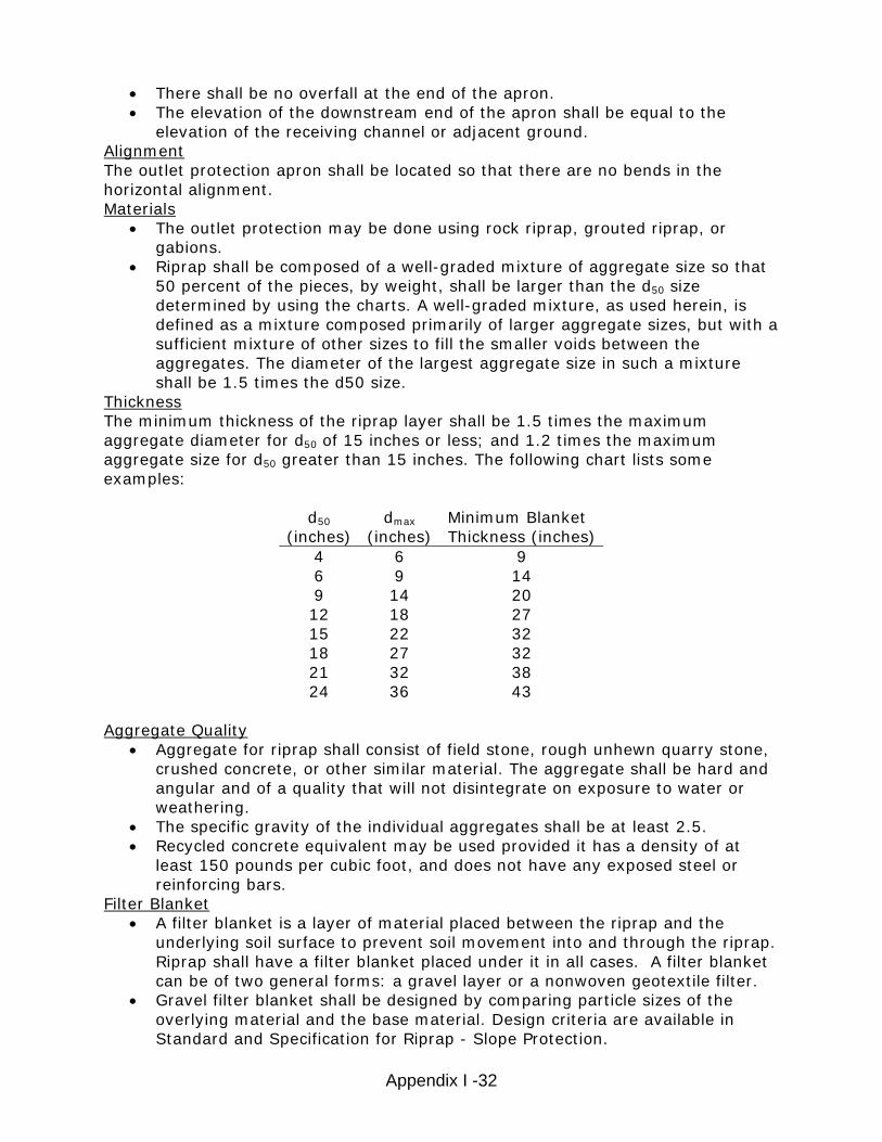
• There shall be no overfall at the end of the apron. • The elevation of the downstream end of the apron shall be equal to the
elevation of the receiving channel or adjacent ground. Alignment The outlet protection apron shall be located so that there are no bends in the horizontal alignment. Materials
• The outlet protection may be done using rock riprap, grouted riprap, or gabions.
• Riprap shall be composed of a well-graded mixture of aggregate size so that 50 percent of the pieces, by weight, shall be larger than the d50 size determined by using the charts. A well-graded mixture, as used herein, is defined as a mixture composed primarily of larger aggregate sizes, but with a sufficient mixture of other sizes to fill the smaller voids between the aggregates. The diameter of the largest aggregate size in such a mixture shall be 1.5 times the d50 size.
Thickness The minimum thickness of the riprap layer shall be 1.5 times the maximum aggregate diameter for d50 of 15 inches or less; and 1.2 times the maximum aggregate size for d50 greater than 15 inches. The following chart lists some examples:
d50 (inches)
dmax (inches)
Minimum Blanket Thickness (inches)
4 6 9 6 9 14 9 14 20 12 18 27 15 22 32 18 27 32 21 32 38 24 36 43
Aggregate Quality
• Aggregate for riprap shall consist of field stone, rough unhewn quarry stone, crushed concrete, or other similar material. The aggregate shall be hard and angular and of a quality that will not disintegrate on exposure to water or weathering.
• The specific gravity of the individual aggregates shall be at least 2.5. • Recycled concrete equivalent may be used provided it has a density of at
least 150 pounds per cubic foot, and does not have any exposed steel or reinforcing bars.
Filter Blanket • A filter blanket is a layer of material placed between the riprap and the
underlying soil surface to prevent soil movement into and through the riprap. Riprap shall have a filter blanket placed under it in all cases. A filter blanket can be of two general forms: a gravel layer or a nonwoven geotextile filter.
• Gravel filter blanket shall be designed by comparing particle sizes of the overlying material and the base material. Design criteria are available in Standard and Specification for Riprap - Slope Protection.

Appendix I -33
• A nonwoven geotextile filter (aka. Filter fabric, geotextile liner, filter cloth) should have properties as identified below:
Aggregate Size
Grab Tensile
Strength (min.) ASTM D4632
Trapezoidal Tear
Strength (min.) ASTM D4533
Puncture Strength (min.) ASTM D4833
Mullen Burst
Strength (min.) ASTM D4833
Permittivity ASTM D4491
Apparent Opening
Size (max.) ASTM D4751
in. lbs lbs lbs lbs per second mm <16 200 75 75 200 0.5 0.21
16-24 270 100 100 400 0.5 0.21 >24 * * * * * *
*As directed by engineer Gabions
• Gabions shall be made of hexagonal triple twist mesh with heavily galvanized steel wire. The maximum linear dimension of the mesh opening shall not exceed 4 ½ inches and the area of the mesh opening shall not exceed 10 square inches.
• Gabions shall be fabricated in such a manner that the sides, ends, and lid can be assembled at the construction site into a rectangular basket of the specified sizes. Gabions shall be of single unit construction and shall be installed according to manufacturer’s recommendations.
• The area on which the gabion is to be installed shall be graded as shown on the drawings. Foundation conditions shall be the same as for placing rock riprap, and filter cloth shall be placed under all gabions. Where necessary, key, or tie, the structure into the bank to prevent undermining of the main gabion structure.
Construction Guidelines
1. The subgrade for the filter, riprap, or gabion shall be prepared to the required lines and grades. Any fill required in the subgrade shall be compacted to a density of approximately that of the surrounding undisturbed material.
2. The rock or gravel shall conform to the specified grading limits when installed respectively in the riprap or filter.
3. Filter cloth shall be protected from punching, cutting, or tearing. Any damage other than an occasional small hole shall be repaired by placing another piece of cloth over the damaged part or by completely replacing the cloth. All overlaps, whether for repairs or for joining two pieces of cloth shall be a minimum of one foot.
4. Aggregate for the riprap or gabion outlets may be placed by equipment. Both shall each be constructed to the full course thickness in one operation and in such a manner as to avoid displacement of underlying materials. The aggregate for riprap or gabion outlets shall be delivered and placed in a manner that will ensure that it is reasonably homogenous with the smaller aggregates and spalls filling the voids between the larger aggregates. Riprap shall be placed in a manner to prevent damage to the filter blanket or filter

Appendix I -34
cloth. Hand placement will be required to the extent necessary to prevent damage to the permanent works.
Monitoring
• Inspect after high flows for evidence of undermining, scour, and/or dislodged aggregates.
Maintenance
• Once a riprap outlet has been installed, the maintenance needs are very low.
References
New York Standards and Specifications For Erosion and Sediment Control

Appendix I -35
Figure 1. Outlet Protection Design—Minimum Tailwater Condition Design of Outlet Protection from a Round Pipe Flowing Full, Minimum Tailwater Condition: Tw < 0.5Do (USDA - NRCS)

Appendix I -36
Figure 2. Outlet Protection Design—Maximum Tailwater Condition Design of Outlet Protection from a Round Pipe Flowing Full, Maximum Tailwater Condition: Tw ≥ 0.5Do) (USDA - NRCS)
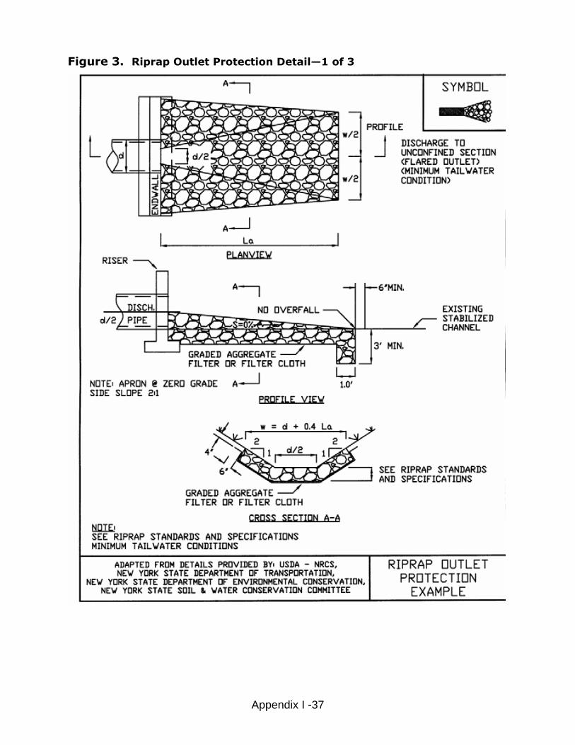
Figure 3. Riprap Outlet Protection Detail—1 of 3
Appendix I -37

Figure 4. Riprap Outlet Protection Detail—2 of 3
Appendix I -38

Figure 5. Riprap Outlet Protection Detail—3 of 3
Appendix I -39

Figure 6. Ordinary High Water Mark
“Ordinary High Water Mark” means the line between upland and bottomland that persists through successive changes in water levels, below which the presence and action of the water is so common or recurrent that the character of the land is marked distinctly form the upland and is apparent in the soil itself, the configuration of the surface of the soil, and the vegetation. On a lake that has a level established by law, it means the high established level. Where water returns to its natural level as the result of the permanent removal or abandonment of a dam, it means the natural ordinary high-water mark.
Ordinary High Water
Water Level
Appendix I -40

Appendix I -41
Rolled Erosion Control Products Definition
Rolled erosion control products (RECPs) consist of prefabricated blankets or netting which are formed from both natural and synthetic materials.
Description and Purpose
The predominantly used RECPs generally fall into the following two categories, each having unique characteristics:
• Erosion control blanket: A temporary degradable rolled erosion control product composed of processed natural or polymer fibers mechanically, structurally or chemically bound together to form a continuous matrix to provide erosion control and facilitate vegetation establishment.
• Turf reinforcement mat (TRM): A rolled erosion control product composed of non-degradable synthetic fibers, filaments, nets, wire mesh and/or other elements, processed into a permanent, three-dimensional matrix. TRMs, which may be supplemented with degradable components, are designed to provide immediate erosion protection, enhance vegetation establishment and provide long-term functionality by permanently reinforcing vegetation during and after maturation. Note: TRMs are typically used in hydraulic applications, such as high flow ditches and channels, steep slopes, stream banks, and shorelines, where erosive forces may exceed the limits of natural, unreinforced vegetation or in areas where limited vegetation establishment is anticipated.
The practice may also be called Erosion Control Blanket, Mulch Blanket, Erosion Control Matting
Pollutant(s) controlled: • Suspended Sediment
Companion and Alternative BMPs
• Seeding/Vegetation Page # BMP Guidebook • Mulching
Advantages and Disadvantages
Advantages: • Can provide for some degree of immediate stabilization • Numerous manufacturers, each with a number of different products, allow for
the selection of a product which meets the individual characteristics of each site. • Stabilizes disturbed slope and protects surface from erosive forces of raindrop
impact.

Appendix I -42
• Promotes growth of vegetation. • Most products degrade over time, eliminating potential maintenance issue. Disadvantages: • Various products and manufacturers have different design and construction
standards. Designer must rely on manufacturer’s data. • Permanent stabilization and protection is dependent on the establishment of
vegetation unless TRMs are used.
Location
Rolled erosion control products should be used on bare ground that is highly susceptible to erosion, such as steep slopes and channels, and in locations where establishing vegetation may otherwise be difficult.
General Characteristics
• Several factors, such as soil conditions, steepness and length of slope, depth of flow, runoff velocities, and time required to establish desired vegetation, influence the choice of product.
• RECPs and TRMs are manufactured from a wide variety of different materials including coconut fiber (coir), jute, nylon, polypropylene, PVC, straw, hay, or wood fibers. These materials may be used individually, or in combination to form nets or blankets.
• The products function by protecting the ground surface from the impact of raindrops and stabilize the surface until vegetation can be established. RECPs and TRMs also promote the growth of vegetation by helping to keep seed in place, and by maintaining a consistent temperature and moisture content in the soil.
• Most RECPs are either biodegradable or photodegradable and will decompose over a period of time.
• RECPs should generally be installed parallel to the direction of water flow.
Materials
• Seed er • Fertiliz
• RECP • Degradable Stakes/Pegs/Pins
• in a wide
variety
Council (ECTC) has developed a uniform product selection guide for RECPs.
Design Specifications
RECPs are produced by a number of manufacturers, and are available variety of different configurations. Competing products from different manufacturers can have completely different material compositions and construction, but be intended to serve the same purpose. Given the wideof RECPs available, product selection and specification can be difficult. Fortunately, the Erosion Control Technology

Appendix I -43
• Table 1 is modified from the product selection guide produced by the ECTC and classifies products based upon longevity and product description.
• Factors such as the slope on which the RECP is to be placed and the sheer stress that the RECP will experience shall be used to determine which RECP product is adequate for the application it is intended for.
• Stake placement and installation should follow manufacturer recommendations
Construction Guidelines
1. Prior to placing a RECP, a topsoil seedbed should be prepared, smooth graded, and seeded and fertilized. It is imperative that seeding occur prior to placement of the RECP to ensure proper contact between seed and soil. Some manufacturers can embed the specified seed mixture into the product during the manufacturing process (if this process is used, follow the manufacturer’s recommended installation specifications).
2. After seeding, the appropriate RECP may be placed and anchored with stakes or staples. The manufacturer will provide specifications for the pattern and spacing of anchor stakes or staples, overlap between rolls (typically 6 inches), and any additional product requirements.
3. It is important that the stakes or staples be properly installed to prevent “tenting” of the product as the vegetation begins to grow and push up on the matting. This can impact vegetative establishment and the product can become entangled in mowing equipment.
4. At the tops of slopes and at the entrance to a channel, the leading edge of the RECP should be trenched into the ground, approximately 6 inches, anchored in place with stakes or staples, and backfilled. This prevents runoff from lifting the leading edge, and flowing between the ground and the RECP.
5. Subsequent segments of RECPs should have their upstream edges trenched in, and the downstream edge should slightly overlap the next section to prevent water from flowing under the product.
Monitoring
Inspect weekly and after every storm event that results in a discharge from the site until adequate vegetation is established.
Maintenance
• Repair erosion and/or undermining at the top of the slope. • Repair undermining beneath RECP(s), pull back the RECP(s), fill and compact
eroded area, reseed and then secure RECP(s) firmly. • Reposition or replace RECPs that have moved along the slope or channel and
secure firmly. • Replace damaged RECPs.

Appendix I -44
References
Erosion Control Technology Council Standard Specification for Rolled Erosion Control Products, 2006. Statewide Urban Design and Specifications, Design Manual 7E-7 10/21/2008 Ontario, Rolled Erosion Control Product (RECP) BMP 11

Appendix I -45
Table 1:
RECP Product Comparison SHORT-TERM - Typical 3 - 12 month functional longevity
Slope Applications*
Channel Applications*
Type Product Description
Material Composition Maximum Gradient
Max. Shear Stress1,2,3
1.A Single-net Erosion Control Blankets & Open Weave Textiles
Processed degradable natural and/or polymer fibers mechanically bound together by a single rapidly degrading, synthetic or natural fiber netting or an open weave textile of processed rapidly degrading natural or polymer yarns or twines woven into a continuous matrix.
3:1 (H:V) 1.5 lbs/ft2(72 Pa)
1.B Double-net Erosion Control Blankets
Processed degradable natural and/or polymer fibers mechanically bound together between two rapidly degrading, synthetic or natural fiber nettings.
2:1 (H:V) 1.75 lbs/ft2(84 Pa)
EXTENDED-TERM - Typical 24 month functional longevity Slope
Applications* Channel
Applications* Type Product
Description Material Composition Maximum
Gradient Max. Shear Stress1,2,3
2.A Erosion Control Blankets & Open Weave Textiles
An erosion control blanket composed of processed slow degrading natural or polymer fibers mechanically bound together between two slow degrading synthetic or natural fiber nettings to form a continuous matrix or an open weave textile composed of processed slow degrading natural or polymer yarns or twines woven into a continuous matrix.
1.5:1 (H:V) 2.00 lbs/ft2(96 Pa)
LONG-TERM - Typical 36 month functional longevity Slope
Applications* Channel
Applications* Type Product
Description Material Composition Maximum
Gradient Max. Shear Stress1,2,3
3.A Erosion Control Blankets & Open Weave Textiles
An erosion control blanket composed of processed slow degrading natural or polymer fibers mechanically bound together between two slow degrading synthetic or natural fiber nettings to form a continuous matrix or an open weave textile composed of processed slow degrading natural or polymer yarns or twines woven into a continuous matrix.
1:1 (H:V) 2.25 lbs/ft2(108 Pa)
1 Required minimum shear stress RECP (unvegetated) can sustain without physical damage or excess erosion (> 12.7 mm (0.5 in) soil loss) during a 30-minute flow event in large-scale testing. 2 The permissible shear stress levels established for each performance category are based on historical experience with products characterized by Manning's roughness coeffecients in the range of 0.01 - 0.05. 3 Acceptable large-scale test methods may include ASTM D 6459, or other independent testing deemed acceptable by the engineer.

Appendix I -46
Table 2 ECTC Standard Specification for Permanent Rolled Erosion Control Products For applications where vegetation alone will not sustain expected flow conditions and/or provide sufficient long-term erosion protection. PERMANENT1 - All categories of TRMs must have a minimum thickness of 0.25 inches (6.35 mm) per ASTM D 6525 and U.V. stability of 80% per ASTM D 4355 (500 hours exposure).
Slope Applications
Channel Applications
Maximum Maximum Type Product Description
Material Composition Gradient Shear Stress1,2
4.A Turf Reinforcement Mat
0.5:1 (H:V) 6.0 lbs/ft2 (288
Pa)
4.B Turf Reinforcement Mat
0.5:1 (H:V) 8.0 lbs/ft2 (384
Pa)
4.C Turf Reinforcement Mat
Turf Reinforcement Mat (TRM) – A rolled erosion control product composed of non-degradable
synthetic fibers, filaments, nets, wire mesh and/or other elements, processed into a permanent,
three-dimensional matrix of sufficient thickness. TRMs, which may be supplemented with
degradable components, are designed to impart immediate erosion protection, enhance vegetation establishment and provide long-term functionality by permanently reinforcing vegetation during and after maturation. Note: TRMs are typically used in hydraulic applications, such as high flow ditches and channels, steep slopes, stream banks, and
shorelines, where erosive forces may exceed the limits of natural, unreinforced vegetation or in
areas where limited vegetation establishment is anticipated.
0.5:1 (H:V) 10.0 lbs/ft2(480 Pa)
1 Required minimum shear stress TRM (fully vegetated) can sustain without physical damage or excess erosion (> 12.7 mm (0.5 in.) soil loss) during a 30-minute flow event in large scale testing.
2 Acceptable large-scale testing protocol may include ASTM D 6460, or other independent testing deemed acceptable by the engineer.
Source: Modified from Erosion Control Technology Council Standard Specification for Rolled Erosion Control Products, 2006.

Exhibit 1:
Rolled Erosion Control Product Channel Installation
Source: Ontario, Rolled Erosion Control Product (RECP) BMP 11
Appendix I -47

Exhibit 2:
Rolled Erosion Control Product Slope Installation
Source: Ontario, Rolled Erosion Control Product (RECP) BMP 11
Appendix I -48

Appendix I -49
Diversions Definition
A diversion is a temporary ridge or excavated channel or combination ridge and channel constructed to divert concentrated and sheet surface water, and possibly subsurface water, from or around areas under construction or development, to sites where it can be used or disposed of.
Description and Purpose
Diversion structures consist of ridges or channels that are used to temporarily divert water around or from an area that is under construction or is being stabilized. Specific applications include perimeter control, diversion away from disturbed slopes, and diversion of sediment-laden water to treatment facilities.
The practice may also be called Interceptor, Berms, or Dikes
Pollutant(s) controlled: • Suspended sediment
Companion and Alternative BMPs
• Riprap - Stabilized Outlet • Rolled Erosion Control Products • Seeding/Vegetation Page # BMP Guidebook •
Advantages and Disadvantages
Advantages: • Reduces the volume of flow across disturbed areas, thereby reducing the
potential for erosion. • Breaks up concentration of water on long slopes. • Maintaining a separation between clean water and sediment-laden water
allows sediment basins and traps to function more efficiently. Disadvantages:
• High flow velocities can cause erosion in the diversion structure. • Diversion structures must be stabilized immediately after installation. • Easily constructed with equipment found on most construction sites and thus
often improperly designed
Location
Diversions are used where: • Runoff from higher areas has potential for damaging properties, causing
erosion, or interfering with, or preventing the establishment of, vegetation on lower areas.
• Surface and/or shallow subsurface flow is damaging sloping upland.

Appendix I -50
nches allowance of 10%. The ridge shall have a
• elocities
•
ent
r second will require some type of lining
• r turf
ent mats (TRM), rock or concrete, as determined by a licensed
• The length of slopes needs to be reduced so that soil loss will be kept to a minimum.
General Characteristics
• All diversions should be designed by a Licensed Professional Engineer • Areas above a diversion should be stabilized with other BMPs to prevent
excessive sediment from accumulating in the diversion channel. • Channel dimensions should be adapted for the equipment that will be used to
maintain the diversion. • The length of the diversion is often fixed by the availability of stabilized outlets. • To prevent scour or excessive seepage a stabilized outlet should be constructed.
Materials
• Seed • Rolled e Riprap
rosion control products •
Design Specifications
• Capacity. Diversion channels designed to protect areas such as minor buildings and roads should have enough capacity to carry the peak runoff expected from a 25-year frequency, 24-hour duration storm. Diversions designed to protect major structures, homes, school buildings and high capacity roads should haveenough capacity to carry the peak runoff from a 100-year frequency 24-hour duration storm.
• Channel Shape. The channel may be parabolic or trapezoidal in shape. The diversion must be designed to have stable side slopes. A ridge placed on the downstream side of the channel must be high enough to keep the runoff in the channel without overtopping. The ridge height should provide at least 6 iof freeboard and a settlement minimum top width of 4 feet Velocity. Channel velocity shall not exceed what is considered non-erosive for the soil and planned stabilization. Table 1 shows maximum permissible vfor vegetated channels. Rolled Erosion Control Products can be used in conjunction with vegetation to provide stabilization at increased velocities. Channel Slope. Runoff Diversion channels must be graded to prevent water standing long enough to drown vegetation in the channel. If possible design velocities greater than 1.5 feet per second should be used to avoid sedimaccumulation in the channel. Steeply sloped channels that generate flow velocities greater than 2.5 feet pematerial other than vegetation. Channel Lining. Channel lining materials may include one or a combination of the following materials: vegetation, synthetic erosion control mats (ECM) oreinforcemEngineer.

Appendix I -51
Outlets. Diversion channels must be able to deliver the runoff to a stable outlet, at a point where outflow type of outlet structure or special lining over the outlet section of the diversion channel may be required
1. f the construction.
uit trenches shall
3. depressions shall be compacted to
6.
7. early during the growing season (prior to October 1). If final seed ns is delayed past October 1, other stabilization measures, su sion control products or riprap
Inspec
••
ey are 50 percent full. • When the work area has been stabilized, remove the ridge and fill in the
channel to blend with the . Remove temporary slope drains and stabilize all disturbed areas with vegetation or other erosion control
References
Maine Erosion and Sediment Control BMP, 3/2003. Water Diversion Dyersburg, Tennessee Erosion Control Handbook. Diversions
• will not cause damage. Some
Construction Guidelines
All ditches or gullies shall be filled, and trees and other obstructions shall be removed before construction begins or shall be part o
2. If underground conduits are located under or through diversions, mechanical compaction, water packing, and installation and backfill of condbe made in advance to allow adequate settlement. Diversion ridges constructed across gullies ora uniform grade to ensure proper functioning of the diversion.
4. Seeded areas need protection during establishment and will be mulched or covered with rolled erosion control products
5. Diversions must be completely stabilized prior to directing runoff to them. Once soil is exposed for a diversion channel, it should be immediately shaped, graded and stabilized. Vegetated diversions need to be stabilized
ing of diversioch as rolled ero
may be required to stabilize the channel.
Monitoring
t weekly and following each storm event.
Maintenance
• Remove debris and sediment from the channel and rebuild and stabilize the ridge as needed.
Check outlets and make necessary repairs immediately. If sediment traps are used as a performance enhancer, remove sedimentfrom traps when th
natural ground
practices.

Table 1:
Diversion Maximum Permissible Design Velocities
1 Annuals—Use only as temporary protection until permanent vegetation is established.
Appendix I -52

Exhibit 1:
Typical Diversion Cross-Sections
Appendix I -53

Appendix I -54
Sediment Basin Definition
A sediment basin is a temporary pond built on a construction site to capture eroded or disturbed soil that is washed off during rain storms, protect neighboring properties, and protect the water quality of a nearby stream, river, lake, wetland or bay.
Description and Purpose
Sediment basins collect and store runoff to allow suspended solids to settle out prior to leaving the site. The primary purpose of sediment basins is to prevent sediment laden runoff from reaching lakes, streams and wetlands.
The practice may also be called settling basins, sumps, debris basins, dewatering basins.
Pollutant(s) controlled: • Suspended solids
Treatment Mechanisms: • Settling causes coarse and medium size particles to settle out in the basin
Pollution Removal Efficiencies: • Sediment basins are not effective in controlling fine particles (i.e. silt, clay) • Sediment basins remove only 70-80 percent of large sized sediment particles
and so should be used in conjunction with other erosion control BMP’s.
Companion and Alternative BMPs
• Riprap – Stabilized Outlet
Advantages and Disadvantages
Advantages: • Cost effective measure for treating sediment laden runoff • Relatively easy to construct
Disadvantages:
• There must be adequate space and topography for the basin to be constructed and for it to function properly.
• Sediment basins must be installed only within the property or special easement limits and where failure of the structure will not result in loss of life, damage to homes or buildings, or interruption of use or service of public roads or utilities.
• Sediment basins are attractive to children and can be very dangerous. Local ordinances regarding health and safety must be adhered to. If fencing of the basin is required, the type of fence and its location should be shown in the SESC plan and in the construction specifications

Appendix I -55
• Sediment basins are only practically effective in removing sediment down toabout the medium silt size fraction. Sediment-laden runoff with smaller sizefractions (fine silt and clay) may not be adequately treated unless chemicaltreatment is used in addition to the sediment basin.
• Standing water may cause mosquitoes or other pests to breed.• Basins require large surface areas to permit settling of sediment. Size may
be limited by the available area.
Location
• Sediment basins are utilized in areas of concentrated flow or points ofdischarge during construction activities.
• Sediment basins shall be constructed at locations accessible for clean out.• Site conditions must allow for runoff to be directed into the basin.• Do not locate sediment basins in perennial streams or wetlands. In-stream
sediment basins are only allowed upon permit by the DEQ, Water Resources Division.
General Characteristics
• Sediment basins should be designed by Licensed Professional Engineers• Sediment basins are designed to be in place until the contributory drainage area
has been stabilized.• Sediment basins are temporary and serve drainage areas up to 100 acres
however other conservation practices are often more economical for smallerdrainage areas.
• Sediment basins should be four times longer than wide (unless baffles are usedto increase the flow length
• The basin depth should be a minimum of two feet deep and no shallower thanthe average distance from the inlet to the outlet (length) divided by 200.
Materials
• Earth• Riprap• Risers• Collars• Seed for stabilization of disturbed soil.
Design Specifications
• ine the size of the drainage area and the
•
dimentation measures, including sediment basins,
Conduct a site investigation to determbest location for the basin or basins. Determine soil types. (If the soils are predominantly clay, the basin size required may be larger than practical. However, if soils are sand or silts therewill be little structural integrity of the basin if constructed with on-site soils. With clay soils it is particularly important to make the best use of soil erosion control measures, because sedo not readily retain clays.)
Appendix I -56
• he sediment basin based on the natural drainage of the area and h
•
ils is much less
• most logical location is usually at the lower end of the
• asins should approximate the pre-development
•
e
iteria
• Se• There ication is based on:
• etween
the or both th
1.
Select the site for t t e soil type.
Determine the number of basins needed. In some cases, it is more effective to have a number of smaller basins rather than on large basin. This is particularly important in areas with larger-grained sediments. In addition, the damage caused by one small basin which fathan the damage caused by one large basin which fails. The area(s) chosen should be such that runoff can be easily diverted tothe basin. The drainage area. The discharge from b runoff from the site. Where neces• sary, the site(s) should also easily accommodate periodic clean-outs. Determine the ultimate fate of the basin. If the basin is to become part ofa storm water runoff “treatment train” upon completion, then the designof the basin must be coordinated with the design of the “future use” of the basin. If the ultimate fate of the basin is an infiltration basin, avoid using heavy equipment in the area so as not to compact the soils. Soils compaction will decrease the ability of the soil to infiltrate water. If thbasin is to be a temporary structure which will be filled and stabilized upon completion of the project, then proceed with the design crbelow.
lect the tion below: appropriate type of basin based on the informaiment basins. Classifare three classes of sed
1. The maximum drainage area a basin serves 2. The height of the dam 3. The extent of the mechanical control devices provided with a basin
If the basin is to be a temporary structure, choose between Class 1 and Class 2 basins. If the structure is to be permanent, then choose b
Class 2 and Class 3 basin and remember that the design criteria fe sediment basin and the storm water basin must be met.
Class 1: This is a simple temporary basin, frequently used on construction sites. This basin consists of an excavated area or anearth embankment or dam less than 3 feet high constructed of the soil or stone which is available on the site. These basins cquickly located and constructed with equipment available on most
an be
es. 2.
construction sites. Stabilization of the embankment with vegetation or paving is necessary. Maximum drainage is 20 acrClass 2: This is a carefully constructed temporary or permanent sediment basin. It consists of an embankment of selectematerials constructed under controlled procedures, with provisions for an emergency discharge for storm water to prevent embankment failure. A class 2 basin is most applicable in situa
d soil
tion
res. 3.
where significant damage can result to downstream and off-site areas if the basin should fail. Maximum drainage is 30 acClass 3: Class 3 basins have carefully engineered, sophisticcontrols and are usually permanent. Both spillways and embankments are intended to serve as grade stabilization structures which will continue to function as storm water control
ated

measures after construction activities are completed. A Class 3 basin should always be constructed if a basin is to be convereted to a permanent storm water detention site. Class 3 basins must be restored to original design specifications prior to conversion to a storm water control. The maximum drainage is 100 acres.
The basin should be stabil• ized before the upstream area is cleared
• dams over six feed in height or more and impounding five
• The f to sett
r the area, the greater
ave emergency spillways).
• e basin shape should be greater than 4:1 (length to width), to
a
area. This is roughly equivalent to 3,600 ft3/acre. •
he length can effectively be “extended” for basins on sites that do not have the r
wer than e average distance from the inlet to the outlet (length) divided by 200
Bas llowing equations:
1. thxDepth 2. than 80,000 ft3
• Disposal sites for the sediment removed from the basin should be incorporated into the overall site plan. Sediment basins with or more surface acres, are regulated under the Dam Safety Act. Other permits may also be needed.
e fectiveness in reducing in-stream velocity and allowing suspended solidsle out depends on the:
• Surface area of the basin. In general the greatethe detention time and the less the flow velocity
• Size of the particles coming into the basin • Concentration of particles coming into the basin
the basin • Rate of flow into• Volume. As sediment accumulates, the volume decreases (as does the
effectiveness of the basin) • Travel distance
• Temporary structures should be designed with an expected life of no more than 3 years. Structures which will be in place longer than that should be designed as permanent structures (i.e. h
• Side Slopes: For safety reasons, the side slopes of sediment basins should beno greater than 2:1 (horizontal to vertical). Use flatter slopes in urban or urbanizing areas for safety and liability. Shape: Thimprove trapping efficiency. Baffles can be used to modify the effective flow distance on shorter basins if the construction site is unable to accommodate 4:1 basin.
• Basin Capacity: At a minimum, the sediment capacity of a sediment basin should be equal volume to contain 1 inch of runoff from the entire drainage
Dimensions: The longer the basin, the more settling will occur. Therefore, at a minimum, the length of the basin should be no less than four times the width.
Tspace to accommodate a 4:1 shape by adding a baffle in the basin perpendiculato the direction of the incoming sediment/water. The basin depth should be a minimum of two feet deep and no shalloth
in dimensions can be determined using the fo
LengthxWidVolume=Basins with Volumes less
8/VolumeWidth =
Appendix I -57

xWidthLength 4=
Appendix I -58
(a constant) 3. more than 80,000 ft3
feetDepth 2=Basins with volumes
3 5.12 xVolumeWidth =
•
prin pdeepethe da
•
• unded by r the top
apped around perforated risers
• i-seep collars to prevent
•
xWidthLength 4= 200/LengthDepth =
• Spillway System: The spillway system should carry the peak runoff from the
sediment basin design storm allowing for a two foot freeboard. The velocity of the flow discharged from the basin should not exceed that allowable for the receiving water body. Principal Spillway (Mechanical Spillway): Class 2 and 3 basins include thedesign of a principal spillway to allow a controlled discharge of water. The
ci le spillway normally consists of a vertical pipe (or riser) located at the st part of the basin, connected to a horizontal pipe which outlets through m or lower slope. The top of the riser should be at least three feet below the top of the damor crest of the emergency spillway. The riser may be solid or perforated. Perforated risers are surrowire mesh and a mound of well graded gravel. A trash rack oveof the riser prevents debris from entering and clogging the spillway. Geotextile fabric should not be wrbecause it can blind off quickly and effectively block the perforations. The horizontal pipe should be provided with antpiping along the outside of the pipe. The outlet of the principal spillway for Class 2 and Class 3 basins should be stabilized with riprap. Follow the specifications for Riprap – stabilized outlet. Class 1 basins will not have a spillway. The size of the principal spillway should be large enough to pass the calculated peak discharge from the drainage area. For Class 1 basithe peak discharge should be based on the storm frequency equivalentthe lifetime of the projec
• 80% of ns, to
t in years, and the Class 2 and Class 3 basins
er priate storm
• Emerg protec by providing an outlet from the basin for runoff volum
• he difference in
• s a storm water basin, the emergency spillway
• etal pipe, or a riprap channel constructed
should be designed on a 10-year and 25-year storm frequency, respectively. If the sediment basin will also be used as a storm watbasin then be sure to design the spillway using the approwater basin procedure. ency Spillway: Class 2 and 3 basins require an emergency spillway to
t the embankment es which exceed the capacity of the principle spillway. The emergency spillway should be sized to pass tdischarge between the design storm frequency and the capacity of the principle spillway. If the basin will be used ashould be designed to pass the 100-year storm. Emergency spillways can be as simple as a slope drain constructed of a half section of corrugated mdown the dam slope.
• The crest of the spillway should be three feet above the crest of the

Appendix I -59
ter
• er. • emergency spillway for Class 2 and Class 3 basins should
• litate installation and reduce the potential for failure
stem. Embankments: The emban constructed with the most
stable fill material availa ents, selected material may have to be hauled in. Where possible, use soils other than sand. Sandy
lines
1. n- sediment basins are only allowed upon permit by the DEQ,
2.
undcover, however,
4. of fill should be in
6. with vegetation.
sins
ilize the area following the seeding, mulching or sodding BMPS.
8. For sediment basins that will o permanent storm watercontrols, the sediment accumulated in the basin during construction, but
• the basin is adequate for storm
mechanical riser and a minimum of two feet above the expected walevel for the design storm. The cross-section should be trapezoidal, with side slopes 3:1 or flattThe outlet of thebe stabilized with riprap. Follow the specifications in the Riprap – stabilized outlet BMP. The emergency spillway for a Class 1 basin can consist of a simple berm alongside the outlet to channel water to a stabilized area.
Riser and Barrel: To facifrom blockage, the minimum barrel size for corrugated metal pipe should be eight inches, and six inches for smooth wall pipe. The cross-sectional area of the riser at least 1.5 times that of the barrel to improve the efficiency of the principal spillway sy
• kments should always beble. For permanent embankm
soils tend to shift.
Construction Guide
Never build a sediment basin in a perennial stream or wetlands. IstreamWater Resources Division. Construct the sediment basins before any other land clearing or grading is done. Construct according to the design and by following the guidelines below. The natural ground under any proposed emba3. nkment or dam should becleared and stripped of trees, other vegetation and roots. The remainder of the basin area should be cleared of trees and larger vegetation to allow easy periodic removal of sediment. Natural grasses and groshould be retained to provide stabilization. Disc or scarify the area where embankment fill will be placed to allow a good bond between the fill and the existing soil. The placement controlled, uniform layers, and should be compacted. Stabilize all exposed areas of the embankment by seeding and mulchi5. ng orsodding. Stabilization of the embankment is particularly important with Class 1 basins since the embankment functions as the spillway. Immediately after the sediment basin is constructed, the top banks of the basin and all surrounding areas should be stabilized
7. After the entire construction project is completed, temporary sediment bashould be dewatered, and then filled in to conform to the contours of the area. The bulkhead and structures should be removed. Stab
be converted t
should be removed to accommodate the conversion.
Monitoring
Check the basin depth to ensure the capacity of

Appendix I -60
• e, and other mechanical damage Check for the presence of soil caking around the perforated riser pipe, which
would prevent proper drainage• Check the outfall to ensure drainage is not causing erosive velocities, and to
ign
• Any problems discovered during the maintenance monitoring should be addressed immediately.
• Sediment removed during cleaning should be placed at an upland area and
References
California Storm water BMP Handbook, Construction. 2003 Sediment Basin Dyersburg, Tennessee. Erosion Control Handbook. Sediment Basin
water and sediment deposition Check the basin for piping, seepag
• from the basin.
ensure the outlet is not clogged.
Maintenance
• Remove sediment when it has accumulated to no more than 50% of the desdepth.
stabilized so that it does not re-enter the drainage course.

Exhibit 1:
Sediment Basin – Standard Riser
Appendix I -61

Exhibit 2:
Sediment Basin – Perforated Riser
Appendix I -62

Exhibit 3:
Sediment Basin – Outlet Riser
Appendix I -63

Exhibit 4:
Sediment Basin – Baffle Placement
Appendix I -64

Appendix I -65
Mulching Definition
Applying coarse plant residue or chips, or other suitable materials, to cover the soil surface.
Description and Purpose
The primary purpose is to provide initial erosion control while a seeding or shrub planting is establishing. Mulch will conserve moisture and modify the surface soil temperature and reduce fluctuation of both. Mulch will prevent soil surface crusting and aid in weed control. Mulch is also used alone for temporary stabilization in nongrowing months
Pollutant(s) controlled: • Suspended Sediments
Companion and Alternative BMPs
• Rolled Erosion Control Products • Hydroseeding • Seeding/vegetation Page # BMP Guidebook • Compost Products Page # BMP Guidebook
Advantages and Disadvantages
Advantages: • Mulch offers a moist, shaded growing zone which reduces plant burn-off • Proper and timely application can help keep seed and soil nutrients or
fertilizer in place. • Mulch can help suppress weed growth
Disadvantages:
• Unanchored mulch can be mobilized in concentrated flow or high wind conditions or when on slopes.
Location
On soils subject to erosion and on new seedings and shrub plantings. Mulch is useful on soils with low infiltration rates by retarding runoff.
General Characteristics
• Site preparation prior to mulching requires the installation of necessary erosion control or water management practices and drainage systems. To keep eroded soil or concentrated runoff away from the mulched area.
• Several types of mulch materials exist, several of the most common are described as follows:
o Straw – Straw is the most commonly used type of mulch, is readily available in most areas, and is effective when applied properly. Use

Appendix I -66
small grain straw (wheat or oat) that is reasonable free of grain and weed seeds or mold. Straw of winter rye is preferable to spring-seeded grains, since fewer weed seeds generally are present. Hay should only be used if straw is not available.
o Wood Chips – Wood chips are suitable for areas which will not be mowed, and around landscaped areas. Wood chips should not be used in areas which are drained by storm sewers, areas subject to flooding, or any other place where they would cause problems if they floated away. Wood chips do not require anchoring, but need to be applied evenly to be effective as an erosion control measure.
o Bark Chips and Shredded Bark – Bark chips and shredded bark are bi-products of timber processing and are often used in landscaping. They may also serve as mulch for areas planted to grasses which are not mowed, and on slopes which are not steep. Applied with a blower, bark chips and shredded bark are less likely to leave the site than wood chips because of their rough edges.
o Compost – Compost can be used as mulch. See the Compost Product BMP on Page # BMP Guidebook for additional details.
• Anchoring should be done at the time of or immediately following the application of the mulch.
• Materials
• Mulch of choice • Seed • Anchoring
Design Specifications
• See Table 1 for specific design specifications by mulch type and Table 2 for specific anchoring selection details
Construction Guidelines
1. Slope, grade and smooth the site to fit needs of selected mulch products. 2. Remove all undesirable stones and other debris to meet the needs of the
anticipated land use and maintenance required. 3. Apply mulch after soil amendments and planting is accomplished or
simultaneously if hydroseeding is used. 4. Select appropriate mulch material and application rate or material needs.
Determine local availability. 5. Select appropriate mulch anchoring material. 6. Anchor mulch immediately after the mulch is applied
Monitoring
• Mulched areas should be checked following each rain to ensure the much is staying in place.
Maintenance

• Maintenance procedures should be followed for the BMPs which were implemented to keep the eroded soil or concentrated runoff away from the mulched area.
References
New York Standards and Specifications for Erosion and Sediment Control. 2005. Mulching
Table 1:
Guide to Mulch Materials, Rates, and Uses
Appendix I -67

Table 2:
Guide to Mulch Anchoring
Appendix I -68

Appendix I -69
Hydroseeding Definition
Hydroseeding is a mechanical method of applying seed, fertilizer, and mulch to land in one step.
Description and Purpose
Hydroseeding typically consists of applying a mixture of wood fiber, seed, fertilizer, and stabilizing emulsion with hydro-mulch equipment, which temporarily protects exposed soils from erosion by water and wind.
The practice may also be called hydro mulching, hydraulic planting, hydraulic mulch seeding, hydraseeding
Pollutant(s) controlled: • Suspended Sediments
Pollution Removal Efficiencies: • Hydroseeding initially reduces sediment generation by 70 to 80% as
compared to sediment production off bare slopes.
Companion and Alternative BMPs
• Mulching • Seeding/Vegetation Page # BMP Guidebook • Rolled Erosion Control Products
Advantages and Disadvantages
Advantages: • Tackifiers can be used with the application to help keep the seed in place • Provides mulching medium around the seed to hold moisture
Disadvantages:
• Hydroseeding may be used alone only when there is sufficient time in the season to ensure adequate vegetation establishment and erosion control. Otherwise, hydroseeding must be used in conjunction with a soil binder or mulching
• Hydroseeding may be inappropriate in dry periods without supplemental irrigation
• Wood fiber hydraulic mulches are generally short-lived (only last a part of a growing season) and need 24 hours to dry before rainfall occurs to be effective.
• May not be able to access remote areas with hydroseeder

Appendix I -70
Location
Hydroseeding is applied on disturbed soil areas requiring temporary protection until permanent vegetation is established or disturbed soil areas that must be re-disturbed following an extended period of inactivity
General Characteristics
• Hydraulic planting mulch is the ingredient that makes the technique possible. Water-laden mulch shot from high-pressure hose or spray gun travels farther than seed and water alone. Once the mulch is on the soil surface, it creates a “mat” or blanket that holds the seed in place, retains soil moisture, resists wind and water erosion, and creates a favorable environment for seed germination.
• Mulch materials may be made from wood chips, newsprint, or corrugated cardboard. Some products may include synthetic poly-based fibers or natural agricultural fibers, paper mill sludge, sawdust, slick papers, or some combination of these.
• Each mulch product group has unique performance characteristics and associated costs. Some materials simply perform the mulch function better than others
• Mulch Fiber length is the key to holding power, while germination is most influenced by moisture holding ability and application rates.
• Virtually any fertilizer formulation can be incorporated into the hydroseeding slurry. It is important to use soil testing to determine the appropriate fertilizer for the site.
• A difficult to access site is best fertilized with a long acting or time-release product at the same time it is seeded. An easily accessible site can be fertilized (again) after germination.
• Tackifier is powdered or granular glue, which when added to the slurry, serves to glue the mulch blanket in place, helping it to withstand wind and rain erosion. Steep slopes are best protected with a tackifier, though any site susceptible to erosion (including that caused by the project’s own irrigation) should be a candidate.
• A wide variety of special use products can be incorporated into the hydroseed slurry when conditions dictate. Soil amendments, such as lime and gypsum, or organics such as sludge and humus can be applied right along with the seed and other ingredients. Dyes, surfactants, growth stimulators, fungicides, inoculants, and a host of other liquid, powdered and granular products are also widely available.
Materials
• Cellulose Fiber Mulch • Fertilizer • Tackifier • Hydro – seed mix.

Appendix I -71
•
Design Specifications
• To select appropriate hydroseeding mixtures, an evaluation of site conditions shall be performed with respect to: • soil conditions • site topography • season and climate • vegetation types • maintenance requirements • sensitive adjacent areas • water availability • plans for permanent vegetation. Paper Mulch is frequently applied at 1,200-1,500 pounds per acre (approximately 25lbs-35 lbs per 1,000 square feet). With a polyacrylamide additive, such rates can be effective. Many contractors avoid using more th2,000-2,500 lbs per acre of paper mulch, bec
an ause too much paper mulch
• tends to crust, and can inhibit germination. Wood Mulch is most effective at rates beginning at 2,000 lbs per acre (about 45 lbs per 1,000 square feet). In very hot conditions, 3,000 lbs (about 70 lbs per 1,000 square feet) per acre will provide more moisture retention, antherefore improve the probability of success significantly. A guar based tackifier is also highly r
d will
ecommended to improve the probability of yielding an
• excellent grass stand. Bonded Fiber Matrix rates start at about 3,000 lbs per acre. At 4,000 lbs peacre (about 90 lbs per 1,000 square feet), most wood based
r
s. • n, rainfall or irrigation is
•
Bonded Fiber Matrix products provide an excellent probability of achieving total coverage of grass, even when pounded with destructive rains or in very hot conditionRegardless of the quality of the mulch protectioalways necessary to produce a stand of grass. Guar tackifier can be used at 25-150 lbs per acre. The standard recommend application rate is 1½ lbs per 1,000 square feet or about 60 lbs per acre. Thisproduct has b
een the mainstay as a glue additive for hydro-mulching for
• of the BMP on Page # BMP
• ding can be accomplished using a multiple-step or one-step
• iple-step process ensures maximum direct contact of the seeds
• t
• cation for too long a period of
time or the applied water will cause erosion.
many years. Seed and fertilizer recommendations are dependent upon the locationarea to be treated. See the Seeding/VegetationGuidebook for specific seed recommendations Hydroseeprocess.
The multto soil. When the one-step process is used to apply the mixture of seed, fiber,etc., the seed rate shall be increased to compensate for all seeds nohaving direct contact with the soil.
• Follow-up applications shall be made as needed to cover weak spots. • The time allowed between placement of seed in the hydraulic mulcher and
the emptying of the hydraulic mulcher tank should not exceed 30 minutes. Application of the slurry should proceed until a uniform cover is achieved. The applicator should not be directed at one lo

Appendix I -72
Construction Guidelines
1. Prior to application, roughen embankment and fill areas by rolling with acrimping or punching type roller or by track walking. Track walking shall onlybe used where other methods are impractical.
2. Hydraulic matrices require 24 hours to dry before rainfall occurs to beeffective
Monitoring
• Hydromulched slopes should be inspected periodically for damage due towind, water, or human disturbance.
Maintenance
• Repair all damaged areas immediately using hydromulching at the originalspecifications or straw mulch.
• Supplemental watering may be required
References
DNRE Storm Water Best Management Practices Catalog, September 2005 Hydromulching Hydroseeding . . . Getting All You Paid For Author: Michael Mellon

Appendix I -73
Dust Control Definition
Control of fugitive dust at construction sites that result from grading, demolition, hauling, and traffic.
Description and Purpose
Dust is generated by vegetation removal plus wind or mechanical movement of soil. Dust may include silty soils, fine sands and clays. Control measures prevent significant movement of soil and attached pollutants
Pollutant controlled: Airborne soil particles (suspended solids) and attached chemicals, including nutrients, pesticides, metals.
Treatment Mechanisms: Cover bare soils and other loose particulates Bind particles (water, chemicals, adhesives) Good housekeeping (sweeping or other removal of free particulates) Control, block, or reduce wind Confine or restrict vehicles and equipment
The practice provides pollution prevention rather than removal.
Companion and Alternative BMPs
Access Road Construction Staging and Scheduling Page # BMP Guidebook Critical Area Stabilization Page # BMP Guidebook Dune/Sand Stabilization Page # BMP Guidebook Mulching Seeding/Vegetation Page # BMP Guidebook Street Sweeping Page # BMP Guidebook
Advantages and Disadvantages
Advantages: Many practices also provide soil erosion and sedimentation control Widely applicable, easy to apply, and many options Multiple benefits: preserves visibility and nuisance conditions on worksites; protects health, equipment, and neighboring property; and maintains soil structure and texture for vegetation establishment
Disadvantages: Controls that may cause water pollution are not well regulated. Used oil and brine

Appendix I -74
wastes are still used today in many areas because of availability and lack of knowledge or concern about environmental impacts
Repeat application is required. Plain water is cheap, readily available, and environmentally benign, but applications daily or more frequently increase labor and fuel costs
Some agents reduce soil permeability and increase runoff rate & volume Chemicals may be expensive or be useful only on specific soil types. Polyacrylamide (PAM) can be very effective but users should be aware of
disadvantages: Each formula must be matched to a specific soil type Overuse can clog soil and reduce infiltration Does not work on coarse soils Not effective if there is snow cover
Many materials or methods require unique equipment to apply Windbreaks require space and they only work when the wind is from one direction Chlorides inhibit vegetative growth so they should not be applied where vegetation will be planted
Lignins are sticky so they are tracked into buildings and onto paved roads Tarps and hard covers do not allow vehicle traffic
Location
Unpaved roads and other areas where soils are bare (construction, demolition, mining, forestry, soil stockpiles
Areas of fine, non-organic soils Open areas lacking windbreaks Where vehicle traffic is heavy such as entrances to construction and demolition sites
Where surface waters are nearby that can be contaminated with dust Where “Built-up” areas are adjacent to project site
General Characteristics
Often sprayed on as a liquid where vehicles travel Solid materials such as tarps may be used for temporary covers of stockpiles and other areas where vehicle traffic does not occur
Not usually required in winter when soils are frozen or during spring thaw when soils are continuously muddy or moist
No single dust control agent is perfect for all sites

Appendix I -75
Materials
Water binds soils by moistening Chlorides draw moisture from the air to make soils self dampening. These include: calcium chloride (flake or liquid), magnesium chloride (liquid), and sodium chloride (table salt)
Lignin sulfonate is a sticky resin by-product from tree pulp which is mixed with water and sprayed on as a soil binder. Marketed by several commercial names
Polyacrylamides (anionic PAM) are long-chain molecules that bind fine particles together by chemical attraction. Do not use cationic PAM which has aquatic toxicity
Vegetable oil penetrates the soil surface and provides binding. Usually soybean oil
Mulch retains soil moisture and covers fine loose soils. Mulches include organic soils and compost
Vegetation binds and covers the soil when established. Regular watering during germination and also mulch will control dust until vegetation is established
Wind barriers reduce the velocity and erosivity of wind. These including: solid board fences, snow fencing, burlap fencing, crate walls, hay bales
Thinned liquid asphalts, asphalt emulsions, and waste oils raise environmental concerns, and should not be used.
Design Specifications
Identify performance objectives for dust controls during project design Use multiple dust control methods and/or a phased approach where no one agent can meet the performance objectives
Minimize soil disturbance by retaining grass, trees and shrubs on project sites as much as possible, and installing Access Roads
Install irrigation systems as a first step where dust is a concern and systems can be protected from construction traffic
Allow adequate space for wind breaks (Construction Barriers). Account for the prevailing wind direction, and place barriers perpendicular to the prevailing direction, spaced evenly at intervals of about 15 times the height of the barrier
Be prepared to apply dust controls when soil disturbance is occurring during hot dry months. For watering without an irrigation system, a truck and driver must be available at all times during dry periods
Anionic PAM: always test soils to identify the appropriate PAM product Covers/tarps over trucks and stockpiles: provide adequate cover and anchor it well against all possible wind events
Street sweeping: brush type sweepers wet the pavement surface to reduce dust movement and bind it temporarily to the pavement. Vacuum type sweepers remove fine particles as well as course ones
Travel on paved routes as much as possible Permanently stabilize soils by paving, vegetating, or adding other landscaping as soon as possible.
Performance Enhancers

Appendix I -76
For gravel/dirt road surfaces, graders with edges that roughen the soil surface aid incorporation of the dust control agent
Pre-wet roads and exposed soils to improve effectiveness of solid dust controls (e.g., calcium chloride)
Construction Guidelines
When large areas require dust control for the first time, test a small area first to determine the effectiveness of agents applied to soils.
Follow manufacturer’s specifications for wind barriers and agents applied to soils Treat areas early in the day if they appear dry and dusty. Early treatment prevents problems later as vehicle traffic and temperatures increase
Limit vehicle speeds on dusty materials and limit vehicle traffic and earth moving on windy days, if possible
Tillage can provide emergency dust control. Use chisel plow blades set about 12” apart, or spring-tooth harrows, or similar plow. Start on the windward side of a project site
Monitoring
Inspect for sedimentation on site. Deposited fines are subject to wind erosion and tracking
Inspect Access Roads and public rights-of-way for tracked sediment Watch for water erosion which results from over watering Watch for dust clouds indicating that reapplication of dust control mechanism is required
Appendix I -77
Maintenance
Reapply liquid or solid agents to control dust by 80% or more Assure that tarps and other solid covers are in place and anchored Provide street sweeping or Access Road maintenance as needed.
References
DMB. 2005. Soil Erosion and Sedimentation Control Guidebook. Specification E5: Dust Control. Infrastructure Services, Facilities Administration, Design & Construction Division. Lansing MI. https://www.michigan.gov/dtmb/0,5552,7-358-82550_60101-155023--,00.html
MDOT. 2006. Soil Erosion and Sedimentation Control Manual. Construction and Technology Support Area. Lansing MI. www.michigan.gov/documents/2006_SESC_Manual_165226_7.pdf
San Juan County. 2005. Construction Best Management Practices, Vol II. BMP C140: Dust Control. Department of Ecology. San Juan County WA.
http://www.mdt.mt.gov/research/projects/env/erosion.shtml USEPA. 2006. Dust Control. National Menu of BMPs, Construction Site Stormwater Runoff Control, Erosion Control. Storm water Program. Washington DC. cfpub2.epa.gov/npdes/stormwater/menuofbmps/index.cfm

Appendix I -78
Polyacrylamide (PAM) Definition
Polyacrylamides (PAMs), are polymer-based materials used to facilitate erosion control and decrease soil sealing by binding soil particles, especially clays, to hold them on site. In addition, these types of materials may also be used as a water treatment additive to remove suspended particles from runoff.
Description and Purpose
PAM increases the soil’s available pore volume, thus increasing infiltration and reducing the quantity of storm water runoff that can cause erosion. Suspended sediments from PAM treated soils exhibit increased flocculation over untreated soils. The increased flocculation aids in their deposition, thus reducing storm water runoff turbidity and improving water quality. PAMs may be used as a water treatment additive to remove suspended particles from runoff. PAMs may also be used to provide an appropriate medium for the growth of vegetation for further stabilization.
Pollutant(s) controlled: • Suspended Solids
Treatment Mechanisms: • Chemical (flocculation & coagulation)
Companion and Alternative BMPs
• Dust Control • Hydroseeding • Sediment Basin
Advantages and Disadvantages
Advantages: • Improves stability of problem soils to prevent soil detachment (i.e. prevents
erosion) in the first place • Provides quick stabilization where vegetation has yet to be established • Promotes flocculation (reduces settling time) of smallest particles • Increases soil pore volume and permeability, thus decreasing imperious
cover • Less obtrusive than some conventional measures - doesn’t interfere with
construction machinery/activity • Convenient and easy to apply and store along with other soil amendments
(fertilizer, mulch, etc.) with conventional seeding, mulching, or irrigation equipment
• Material is specifically designed for the soil, waters, and other on site characteristics
• May prevent costly repair and reshaping of rilling or failing slopes

Appendix I -79
• Re-application may not be necessary for several months if treated areas are mulched
• Reduces seed, pesticide, and fertilizer (phosphorus and nitrogen) losses that hinder vegetation establishment on site, increase costs, and promote nutrient and chemical loading offsite
• Reduces windborne dust conditions Disadvantages:
• Materials are soil type-specific so a contractor cannot use leftover material at another site or bulk order for multiple sites.
• Using it requires site-specific testing that may take several days to complete. • Overuse may clog soils, thereby decreasing infiltration. • It is not effective when applied to pure sand or gravel with no fine silts or
clays, nor when applied over snow cover. • PAM shall not be directly applied to water or allowed to enter a water body. • Do not use PAM on a slope that flows into a water body without passing
through a sediment trap or sediment basin. • PAM will work when applied to saturated soil but is not as effective as
applications to dry or damp soil. • Some PAMs are more toxic and carcinogenic than others. Only the most
environmentally safe PAM products should be used. • The specific PAM copolymer formulation must be anionic. Cationic PAM
shall not be used in any application because of known aquatic toxicity problems.
• A review of scientific literature and field demonstrations has identified several forms of PAMs that are potentially toxic to the aquatic environment and not suitable for use in Michigan. These toxic forms include:
o Non-food grade PAMs. These PAMs contain residual monomer acrylamides in concentrations that may be toxic in the environment. Only food grade (National Sanitary Foundation/American National Standards Institute) or products containing less than 0.05 percent residual monomer by volume should be used.
o Any cationic PAM or a form other than an anionic polymer. Only anionic forms of PAMs demonstrate non-toxic qualities.
o Emulsion-based PAMs or any polymer that is pre-mixed in a substance other than pure water. Some of these emulsions have a surfactant base for easy application. While the polymer may not be toxic, some emulsions demonstrated significant toxicity during field trials
Location
PAM can be applied to the following areas: • Rough graded soils that will be inactive for a period of time. • Final graded soils before application of final stabilization (e.g., paving,
planting, mulching). • Temporary haul roads prior to placement of crushed rock surfacing. • Compacted soil road base. • Construction staging, materials storage, and layout areas. • Soil stockpiles. • Areas that will be mulched.

Appendix I -80
General Characteristics
• PAM can be used in several forms:o Powdero Powder added to water (wet, as a stock solution)o Emulsiono Gel Blocks or Bricks
• When used correctly and in concert with existing erosion control bestmanagement practices (BMPs), land applied PAMs should not enter surfacewaters of the state.
• PAMs are manufactured in various forms to be used on specific soil types,and are generally applied at a rate of up to 10 pounds/acre.
• Using the wrong form of a PAM on a soil will result in some degree ofperformance failure, and increase the potential for this material to entersurface waters.
• The use of PAMs as a soil erosion control should be listed with all other BMPsas part of your soil erosion control plan.
• Pam shall be used in conjunction with other BMPs and not in place of otherBMPs, including both erosion controls and sediment controls.
• Storm water runoff from PAM treated soils should pass through a sedimentcontrol BMP prior to discharging to surface waters.
• PAM can be applied to wet soil, but dry soil is preferred due to less sedimentloss.
• Keep the granular PAM supply out of the sun. Granular PAM loses itseffectiveness in three months after exposure to sunlight and air.
• Proper application and re-application plans are necessary to ensure totaleffectiveness of PAM usage.
• PAM, combined with water, is very slippery and can be a safety hazard. Caremust be taken to prevent spills of PAM powder onto paved surfaces. Duringan application of PAM, prevent over spray from reaching pavement, aspavement will become slippery. If PAM powder gets on skin or clothing, wipeit off with a rough towel rather than washing with water this only makescleanup messier and longer.
• PAM tackifiers are available and being used in place of guar and alphaplantago. Typically, PAM tackifiers should be used at a rate of no more than0.5-1 lb per 1,000 gallons of water in hydro mulch machine. Some tackifierproduct instructions say to use at a rate of 3-5 lbs per acre, which can be toomuch. In addition, pump problems can occur at higher rates due to increasedviscosity.
• Prior to the application of polyacrylamides [PAMs] directly within“Surface Waters of the State”, MDNRE must approve their use. Toobtain approval, specific project information must be submitted to andreviewed by MNRE. All requests involving the use of PAMs in direct contactwith surface water, including facilities covered by National PollutantDischarge Elimination System permits through Permit by Rule, or soil erosionand sedimentation control permits or plans, must be submitted to:
o Ms. Diana Klemans of the Surface Water Assessment Section, Water Resources Division, P.O. Box 30458, Lansing, Michigan 48909.
o Requests should include the following:applicant’s name and addressthe specific application location

Appendix I -81
area and frequency of treatment name and amount of Pam(s) being used the name and location of receiving surface waters Please specify if the characteristics of the PAM(s) meet the
guidelines specified above and if on-site soil or sediment characteristics have been identified and matched to the appropriate polymer
Materials
• Polyacrylamide • Mulch
Design Specifications
• PAM may be applied in dissolved form with water, or it may be applied in dry, granular, or powered form. The preferred application method is the dissolved form.
• PAM is to be applied at a maximum rate of ½ pound PAM per 1000 gallons water per 1 acre of bare soil. Table 1 and Figure 1 can be used to determine the PAM and water application rate for a disturbed soil area. Higher concentrations of PAM do not provide any additional effectiveness.
Construction Guidelines
1. Pre-measure the area where PAM is to be applied and calculate the amount of product and water necessary to provide coverage at the specified application rate (1/2 pound PAM/1000 gallons/acre).
2. PAM has infinite solubility in water, but dissolves very slowly. Dissolve pre-measured dry granular PAM with a known quantity of clean water in a bucket several hours or overnight. Mechanical mixing will help dissolve the PAM. Always add PAM to water – not water to PAM.
3. Pre-fill the water truck about 1/8 full with water. The water does not have to be potable, but it must have relatively low turbidity – in the range of 20 NTU or less.
4. Add the dissolved PAM and water mixture to the truck. 5. Fill the water truck to specified volume for the amount of PAM to be applied. 6. Spray the PAM/water mixture onto dry soil until the soil surface is uniformly and
completely wetted 7. PAM may also be applied as a powder at the rate of 5 lbs per acre. This must be
applied on a day that is dry. For areas less than 5-10 acres, a hand held “organ grinder” fertilizer spreader set to the smallest setting will work. Tractor mounted spreaders will work for larger areas.
Monitoring
• Inspect BMPs prior to forecast rain, daily during extended rain events, after rain events, weekly during the rainy season, and at two-week intervals during the non-rainy season.

Maintenance
• Areas where erosion is evident should be repaired and BMPs re-applied as soon as possible. Care should be exercised to minimize the damage to protected areas while making repairs, as any area damaged will require re-application of BMPs.
• PAM must be reapplied on actively worked areas after a 48-hour period if PAM is to remain effective.
• Reapplication is not required unless PAM treated soil is disturbed or unless turbidity levels show the need for an additional application.
• If PAM treated soil is left undisturbed a reapplication may be necessary after two months.
• More PAM applications may be required for steep slopes, silty and clayey soils (USDA Classification Type “C” and “D” soils), long grades, and high precipitation areas.
• When PAM is applied first to bare soil and then covered with straw, a reapplication may not be necessary for several months.
• Rinse all PAM mixing and application equipment thoroughly with water to avoid formation of PAM residues
• Downstream deposition from the use of PAM may require periodic sediment removal to maintain normal functions
References
California Storm water BMP Handbook, Construction, 2003 Polyacrylamide
Table 1:
Appendix I -82