Embed Size (px)
Citation preview

APPED-101054AConfidential
Part 4…Isolated DC/DC (types, operations, sales guide, etc.)
Application information
Power supply unit (PSU)
©2010. Renesas Electronics Corporation, All rights reserved.
Sep. 2011 Rev.1.0
General Purpose Systems Marketing Dept.General Purpose Systems DivisionMarketing Unit
Renesas Electronics Corporation
Confidential
APPED-101054A Confidential
Introduction to Part4 Purpose
This course provides basic knowledge of power supply units
Objectives Learn about types of isolated DC/DC Learn about isolated DC/DC operation Learn about the sales guide for isolated DC/DC ICs
Contents 21 pages
Learning Time 30 minutes
2 ©2010. Renesas Electronics Corporation, All rights reserved.

APPED-101054A
Types of isolated DC/DC
3 ©2010. Renesas Electronics Corporation, All rights reserved.
APPED-101054A Confidential
Is isolated DC/DC IC same as PWM IC?
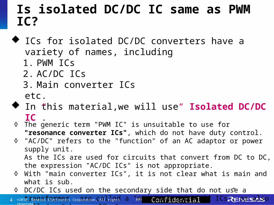
ICs for isolated DC/DC converters have a variety of names, including1. PWM ICs2. AC/DC ICs3. Main converter ICsetc.
In this material,we will use“ Isolated DC/DC IC”.
◊ The generic term "PWM IC" is unsuitable to use for "resonance converter ICs", which do not have duty control.
◊ "AC/DC" refers to the "function" of an AC adaptor or power supply unit.As the ICs are used for circuits that convert from DC to DC, the expression "AC/DC ICs" is not appropriate.
◊ With "main converter ICs", it is not clear what is main and what is sub.◊ DC/DC ICs used on the secondary side that do not use a transformer
are called a "non-isolated DC/DC ICs”, or also called a "chopper ICs."
4 ©2010. Renesas Electronics Corporation, All rights reserved.

APPED-101054A Confidential
The major types are shown in below There are other types besides these, such as push-pull, RCC, etc., but we will not talk about them here.
Feedback circuits are not shown in the figures.
Which type to be use in PSU is decided mainly by power range.
Types of isolated DC/DC
5 ©2010. Renesas Electronics Corporation, All rights reserved.
APPED-101054A Confidential
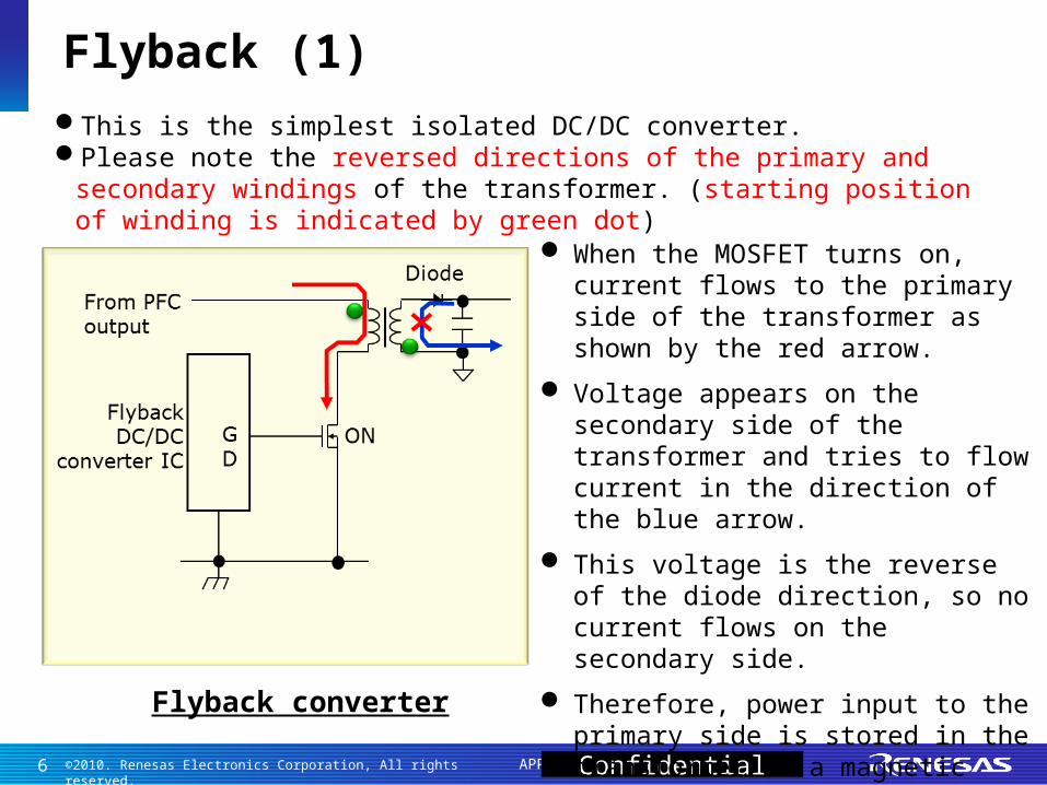
This is the simplest isolated DC/DC converter.Please note the reversed directions of the primary and secondary
windings of the transformer. (starting position of winding is indicated by green dot)
Flyback converter
When the MOSFET turns on, current flows to the primary side of the transformer as shown by the red arrow.
Voltage appears on the secondary side of the transformer and tries to flow current in the direction of the blue arrow.
This voltage is the reverse of the diode direction, so no current flows on the secondary side.
Therefore, power input to the primary side is stored in the transformer as a magnetic field.
Flyback (1)
6 ©2010. Renesas Electronics Corporation, All rights reserved.

APPED-101054A Confidential
When the MOSFET turns off, the primary side current of the transformer turns off.
The energy stored in the transformer generates voltage to generate current in the direction of the blue arrow on the secondary side, and the capacitor is charged.
The IC monitors the output voltage using a feedback circuit, (not shown in the left fig.) and controls the duty of the MOSFET gate pulse to regulate output voltage.
Flyback converter
Flyback (2)
7 ©2010. Renesas Electronics Corporation, All rights reserved.

APPED-101054A Confidential
Please note that the direction of the primary and secondary windings of the transformer are the same, and that there is a inductor on the secondary side.
Forward converter
When the MOSFET turns on, current flows to the primary side of the transformer as shown by the red arrow.
Current flows in the secondary side of the transformer as shown by the blue arrow, passes through the inductor, and charges the capacitor.
Energy is stored in the inductor during this period.
Forward (1)
8 ©2010. Renesas Electronics Corporation, All rights reserved.

APPED-101054A Confidential
Forward converter
On the other hand, using the energy stored in the inductor, current flows as shown by the blue arrow, charging the capacitor.
Since most of power input to the primary side is transmitted to the secondary side while the MOSFET is on (the transformer does not store much energy),
a smaller transformer than flyback can be used.
Forward is suitable for higher power applications than flyback.
When the MOSFET turns off, a voltage trying to flow current in the direction of the yellow arrow appears in the secondary winding of the transformer, but because it is in the reverse direction of the diode, no current flows in the secondary winding of the transformer.
Forward (2)
9 ©2010. Renesas Electronics Corporation, All rights reserved.
APPED-101054A Confidential
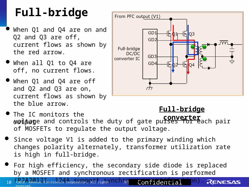
When Q1 and Q4 are on and Q2 and Q3 are off, current flows as shown by the red arrow.
When all Q1 to Q4 are off, no current flows.
When Q1 and Q4 are off and Q2 and Q3 are on, current flows as shown by the blue arrow.
The IC monitors the outputvoltage and controls the duty of gate pulses for each pair of MOSFETs to regulate the output voltage.
Since voltage V1 is added to the primary winding which changes polarity alternately, transformer utilization rate is high in full-bridge.
For high efficiency, the secondary side diode is replaced by a MOSFET and synchronous rectification is performed (R2A20121, 124A support synchronous rectification).
Full-bridge converter
Full-bridge
10 ©2010. Renesas Electronics Corporation, All rights reserved.

APPED-101054A Confidential
Soft switching is switching when the MOSFET source-drain voltage or current is zero or close to zero.
Soft switching is available for each type of isolated DC/DC (next page).
Soft switching can reduce the amount of heat and noise generated, so it is used for situations where high efficiency and low noise are important.
Example of zero current switching Example of zero voltage switching
Soft switching
11 ©2010. Renesas Electronics Corporation, All rights reserved.

APPED-101054A Confidential
Flyback: By monitoring ZCD winding in the transformer, turns the MOSFET from off to on at the same time secondary side current becomes zero (zero current switching: ZCS). -> This type is called a (flyback) quasi-resonant converter.
Half-bridge: Connect an inductor and a capacitor in series to the transformer, and make them resonate. The shape of the current waveform flowing through the transformer approaches a sinusoidal wave, reducing noise. -> This type is called an LLC resonant converter.
Quasi-resonant converter (flyback) LLC resonant converter (half-bridge)
Soft switching Flyback and Half-bridge examples.
12 ©2010. Renesas Electronics Corporation, All rights reserved.

APPED-101054A Confidential
The figures on the right show the phase shift method.
In phase shift, each MOSFET (Q1-Q4) are turned on and off independently.
When Q1 and Q4 are on, current flows as shown in fig. a.
Then, Q4 is turned off, the Q4 capacitor is charged and the voltage of the capacitor becomes V1, and the Q3 capacitor discharges to 0 (fig. b).
At this time, Q3 is turned on (fig. c).
Next, Q1 is turned off (fig. d).
The Q1 capacitor is charged and becomes V1, and the Q2 capacitor is discharged to 0.
Full-bridge soft switching (1)
13 ©2010. Renesas Electronics Corporation, All rights reserved.

APPED-101054A Confidential
Q2 is turned on next, the current is as shown in fig. e, which is the opposite of fig. a on the previous slide.
After this, performing Q3 off -> Q4 on -> Q2 off -> Q1 on will return to fig. a on the previous slide.
Each MOSFET carries out ZVS (zero voltage switching), so efficiency improves.
The phase of the gate signal is shifted and the period when Q1 and Q4 or Q2 and Q3 turn on simultaneously is controlled.
Full-bridge soft switching (2)
14 ©2010. Renesas Electronics Corporation, All rights reserved.
APPED-101054A Confidential
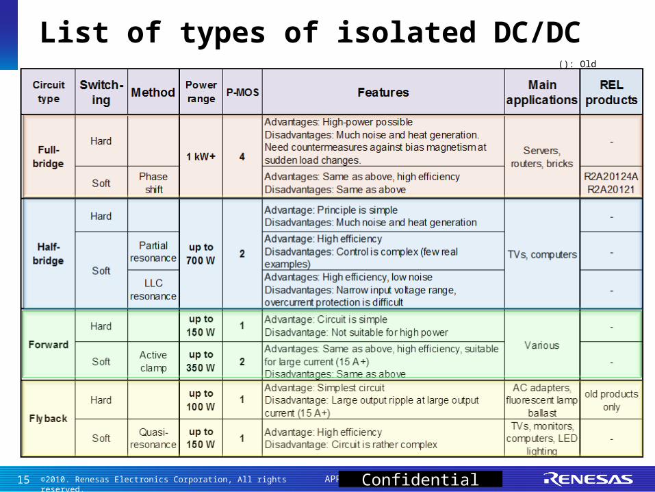
(): Old product
List of types of isolated DC/DC
15 ©2010. Renesas Electronics Corporation, All rights reserved.

APPED-101054A
Sales guide for isolated DC/DC
16 ©2010. Renesas Electronics Corporation, All rights reserved.

APPED-101054A Confidential
Renesas is focusing on promoting full-bridge phase shift IC in isolated DC/DC area.
Full-bridge phase shift (soft switching) with synchronous rectification
• R2A20124A (improved version of R2A20121)• R2A20121
Suitable for over 1 kW systems, such as• Servers• Base stations• Office routers• Rapid charging stands for electric and hybrid
vehicles (not in-vehicle)
Please promote for the above applications.
Sales guide
17 ©2010. Renesas Electronics Corporation, All rights reserved.

APPED-101054A Confidential
The following items intended for customers are available. Please use them.
One-page guide: One-page summary of IC features
Presentation: Overview of ICs. Can provide to customer.
Datasheet: Explanation and specification of IC
Application notes: Explanation of evaluation board, design examples summarized
Excel sheet: For calculating circuit constants of external parts (R2A20124A)
Evaluation boards: Boards used for evaluation (all may be lent out) (R2A20124A)
IC samples:
Sales guide (documents and tools)
18 ©2010. Renesas Electronics Corporation, All rights reserved.

APPED-101054A
Supplement: Feedback circuit of isolated DC/DC converter
19 ©2010. Renesas Electronics Corporation, All rights reserved.
APPED-101054A Confidential
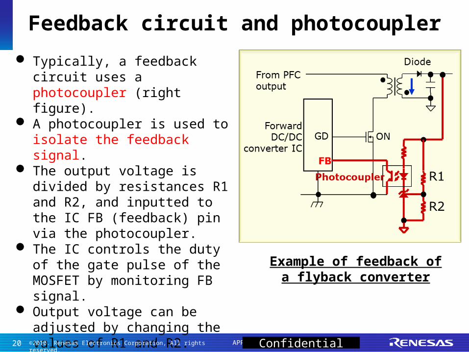
Typically, a feedback circuit uses a photocoupler (right figure).
A photocoupler is used to isolate the feedback signal.
The output voltage is divided by resistances R1 and R2, and inputted to the IC FB (feedback) pin via the photocoupler.
The IC controls the duty of the gate pulse of the MOSFET by monitoring FB signal.
Output voltage can be adjusted by changing the values of R1 and R2.
Example of feedback ofa flyback converter
Feedback circuit and photocoupler
20 ©2010. Renesas Electronics Corporation, All rights reserved.

©2011. Renesas Electronics Corporation. All rights reserved.
Renesas Electronics Corporation.
Thank You
Thank you
Confidential