Embed Size (px)
Citation preview
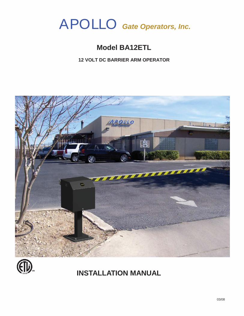
APOLLO Gate Operators, Inc.
Model BA12ETL12 VOLT DC BARRIER ARM OPERATOR
INSTALLATION MANUAL
03/08
2
CONTENTS
IMPORTANT SAFETY INSTRUCTIONS ............................................................. 3
Applications ................................................................................................... ..... 4
Pre-Installation Checklist ............................................................................ ...... 5
Operator Installation ...................................................................................... .... 6
Orientation ………..………………………………………………………………..…. 7
Arms and Counterweight ................................................................................... 8
Power Connections .......................................................................... ................. 9
Programming Current Sensing ……………………………………………………. 10
Control Board .................................................................................................... 11-15
Siren Connection ………………………………………………………………….…. 16
Radio Receiver Options ………………………………………………………….…. 17
Specifications …………………………………………………………………………. 18
Warranty ...................................................................................................... ........ 19

3
WARNING - To reduce the risk of injury or death:READ AND FOLLOW ALL INSTRUCTIONS.
Installation should be performed by a professional installer.
Should electricity be required, use a certified electrician only.
Any device that requires 120 Volts AC should be U.L. approved.
Install control devices such as keypads far enough away (5 feet or further) from anymoving parts of the operator and gate to prevent possible injury.A secondary entrapment device such as loop detectors, edge switches, and beamdetectors are highly recommended and required to meet the UL325 standard.
Review with the owner all safety concerns including:
Do not operate the gate/arm unless area around gate/arm is in full view.
Never let children operate or play with operator controls. Keep the remote con-trol away from children.
Always keep people and objects away from the gate/arm. NO ONE SHOULDCROSS THE PATH OF THE MOVING GATE/ARM.
Test the operator monthly (see STEP 7 Programming the current sensitivity).
The gate/arm MUST reverse on contact with a rigid object or stop when an ob-ject activates the non-contact sensors. After adjusting the force or limit oftravel, retest the operator. Failure to adjust and retest the gate operator prop-erly can increase the risk of injury or death.
Arrange with local fire and law enforcement for emergency access.
Always disconnect the battery or power source when making adjustments orrepairs to any part of the operator.
The entrance is for vehicles only. Pedestrians must use separate entrance.
SAVE THESE INSTRUCTIONS
IMPORTANT SAFETY INSTRUCTIONS
4
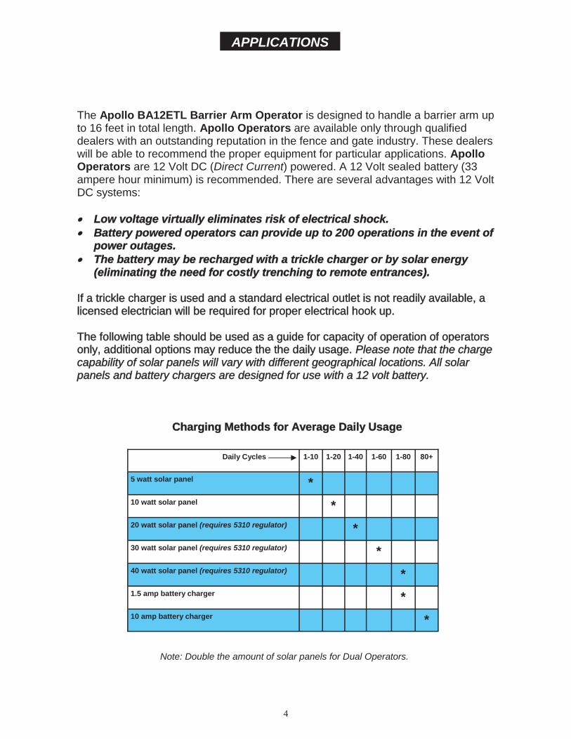
The Apollo BA12ETL Barrier Arm Operator is designed to handle a barrier arm upto 16 feet in total length. Apollo Operators are available only through qualifieddealers with an outstanding reputation in the fence and gate industry. These dealerswill be able to recommend the proper equipment for particular applications. ApolloOperators are 12 Volt DC (Direct Current) powered. A 12 Volt sealed battery (33ampere hour minimum) is recommended. There are several advantages with 12 VoltDC systems:
Low voltage virtually eliminates risk of electrical shock.Battery powered operators can provide up to 200 operations in the event ofpower outages.The battery may be recharged with a trickle charger or by solar energy(eliminating the need for costly trenching to remote entrances).
If a trickle charger is used and a standard electrical outlet is not readily available, alicensed electrician will be required for proper electrical hook up.
The following table should be used as a guide for capacity of operation of operatorsonly, additional options may reduce the the daily usage. Please note that the chargecapability of solar panels will vary with different geographical locations. All solarpanels and battery chargers are designed for use with a 12 volt battery.
Charging Methods for Average Daily Usage
Daily Cycles 1-10 1-20 1-40 1-60 1-80 80+
5 watt solar panel *10 watt solar panel *20 watt solar panel (requires 5310 regulator) *30 watt solar panel (requires 5310 regulator) *40 watt solar panel (requires 5310 regulator) *1.5 amp battery charger *10 amp battery charger *
Note: Double the amount of solar panels for Dual Operators.
APPLICATIONS

5
The following checklist should be used before beginning installation:
• Verify that the proper operator has been selected for this application.
• Determine the general location of the operator, access controls, and solarpanel (if used).
1. Is there a suitable location for the operator?2.Can the solar panel (if used) be mounted in an unobstructed area facing south?3. Will additional solar panel cable be required?4. Is electricity available (if required)?
• Consider safety and access options. Recommend if needed.
1. Will there be chidren or animals in the area?2. Are safety loops, edge switches, or photo eye detectors required?3. How can the arm be opened in emergencies?4. How will visitors enter and exit?5. Will vehicles (and trailers) have sufficient room off roadway to operate access control devices such as keypads?
PRE-INSTALLATION CHECKLIST

6
OPERATOR INSTALLATION
The BA12ETL is designed to be mounted to a 15”x15” (minimum) concrete pad. Four 1/2” concrete anchor bolts arerequired for proper installation. PVC conduit should be in position prior to pouring the pad if remote access control de-vices or loops are to be used. The concrete pad should be a minimum of 12” below the ground level.
Most installations will be on the left side (driver’s side) of the driveway.
Set the BA12ETL on the concrete pad at a desiredposition.
Using a 1/2” concrete drill bit, drill four holes usingthe pedestal base as a template.
Install (4) 1/2” concrete anchor bolts and securewith washers and nuts.
1/2” ConcreteAnchor Bolt

7
OrientationSTEP 1. Determine which side of the driveway the operator is to be mounted. The factory units are set up to be installedon the left (driver’s) side of the driveway as shown in Fig. A.
Fig. ALeft side of driveway
The operator and surge board connection is shown for the standard installation as shipped from factory.
Front
Surge Board
Loosen the clamp bolt and rotate the arm assembly 90 degrees clockwise.
Clamp Bolt
12
If the operator is to be installed on the right side of the driveway you may simply install the unit in a reverse positionor if preferred you can reverse the operation as shown below.
Operator to be installed on the left side of the driveway
Operator to be installed on the right side of the driveway
The operator is now in the openposition for right side operation.
Relocate the removable plug toINPUT B on the surge board.
3
Fig. BRight side of driveway

8
ARMS & COUNTERWEIGHT
Various types and lengths of arms (up to 16 feet) may beused with the BA12ETL.
The simplest and least expensive arm is the PVC down-spout available at The Home Depot home improvementstore sold in 10 foot lengths and may be easily cut down toany shorter size. A counter weight is not required for thistype of arm.
Loosen clamp bolt enough soassembly can slip on shaftwhen pressure applied
The arm assembly can be balanced by adjusting the counter-weights and/or aluminum extrusion. Once balanced, level armassembly and tighten all hardware
Clamp Bolt
Aluminum Extrusion
20 lb.Counterweight
Aluminum and wood arms may require one or two optional counterweights de-pending on the length of the arm. As a general rule, any aluminum or woodarm over 10 feet should be counterweighted.
Arm Assembly Balance

9
POWER CONNECTIONS
A 12 volt sealed lead acid battery rated for 34 amperehours is recommended for the BA12ETL.
The battery may be recharged with a electrical batterycharger or solar panel. A 6 amp automatic battery chargeris sufficient for most applications. If solar charging is arequirement contact our customer service department at800 226-0178 to help determine the solar panel sizeneeded.
G-CELL12 Volt 34aH Sealed Battery
Connect the two ring terminals on the con-nector end of the cable to the battery. Thebattery charger or solar panel should beinstalled at this time.
(RED is positive(+) and Black is negative(-)
Plug the main connector into the Master con-nector on the circuit board.
The operator is now activated. The current sense must now be programmed as shown on page 10.
If the operator does not work, check the battery connections for proper polarity. If the connectionsare reversed, the “REVERSE BATTERY POLARITY” LED will be illuminated at the bottom center ofthe circuit board.
10
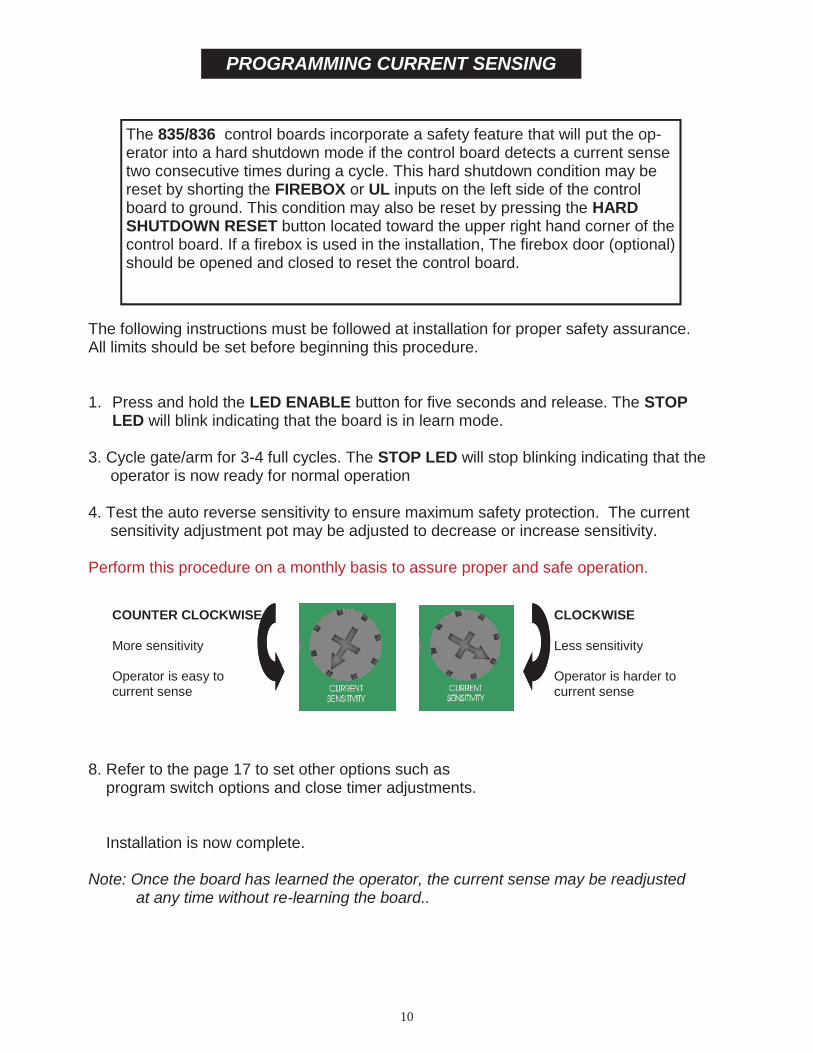
PROGRAMMING CURRENT SENSING
The 835/836 control boards incorporate a safety feature that will put the op-erator into a hard shutdown mode if the control board detects a current sensetwo consecutive times during a cycle. This hard shutdown condition may bereset by shorting the FIREBOX or UL inputs on the left side of the controlboard to ground. This condition may also be reset by pressing the HARDSHUTDOWN RESET button located toward the upper right hand corner of thecontrol board. If a firebox is used in the installation, The firebox door (optional)should be opened and closed to reset the control board.
The following instructions must be followed at installation for proper safety assurance.All limits should be set before beginning this procedure.
1. Press and hold the LED ENABLE button for five seconds and release. The STOPLED will blink indicating that the board is in learn mode.
3. Cycle gate/arm for 3-4 full cycles. The STOP LED will stop blinking indicating that the operator is now ready for normal operation
4. Test the auto reverse sensitivity to ensure maximum safety protection. The current sensitivity adjustment pot may be adjusted to decrease or increase sensitivity.
Perform this procedure on a monthly basis to assure proper and safe operation.
8. Refer to the page 17 to set other options such as program switch options and close timer adjustments.
Installation is now complete.
Note: Once the board has learned the operator, the current sense may be readjustedat any time without re-learning the board..
CLOCKWISE
Less sensitivity
Operator is harder tocurrent sense
COUNTER CLOCKWISE
More sensitivity
Operator is easy tocurrent sense
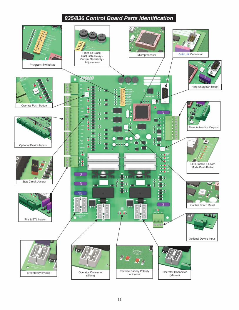
11
LED Enable & LearnMode Push Button
Optional Device Inputs
Stop Circuit Jumper
Fire & ETL Inputs
Emergency Bypass Reverse Battery PolarityIndicators
Optional Device Input
Remote Monitor Outputs
GateLink ConnectorMicroprocessorTimer To Close -Dual Gate Delay -
Current Sensitivity -Adjustments
Program Switches
835/836 Control Board Parts Identification
Operator Connector(Master)
Operator Connector(Slave)
Control Board Reset
Hard Shutdown Reset
Operate Push Button

12
Board Harness Function
Pin 1 Orange Open LimitPin 2 White Close LimitPin 3 Black Motor (positive on open, negative on close)Pin 4 Red Motor (negative on open, positive on close)Pin 5 Green Common for both limit switchesPin 6Pin 7 Black Battery NegativePin 8 Red Battery Positive
13
57
24
68
Master/Slave Connector
Applies battery voltage directly to motor to open gate (will not close gate) ifcontrol board fails. User must unplug before gate opens to maximum travel orthe 15 amp fuse will open. Fuse should be checked before returning gate toservice.
EMERGENCY BYPASS
Connects control board to a computer using GateLink software. This softwarecan monitor and diagnose the functions of the microprocessor. Ask your sales-person about this feature.
GateLink Connector
12V Supplied battery voltage
SLV Slave Operator Indicator (indicates slave side of gate is closed)+12V when on closed limit. Ground when off of closed limit.
MAS Master Operator Indicator (indicates master side of gate is closed)+12V when on closed limit. Ground when off of closed limit.
GND Battery supplied ground
SIREN Connect to siren +applies +12V when gate(s) are running, or in hard shutdown
GND Battery supplied ground
LOCK Connect to lock + (optional) Magnetic or Solenoid type locks (Dip Switch #6 Selectable)
Remote Outputs
13
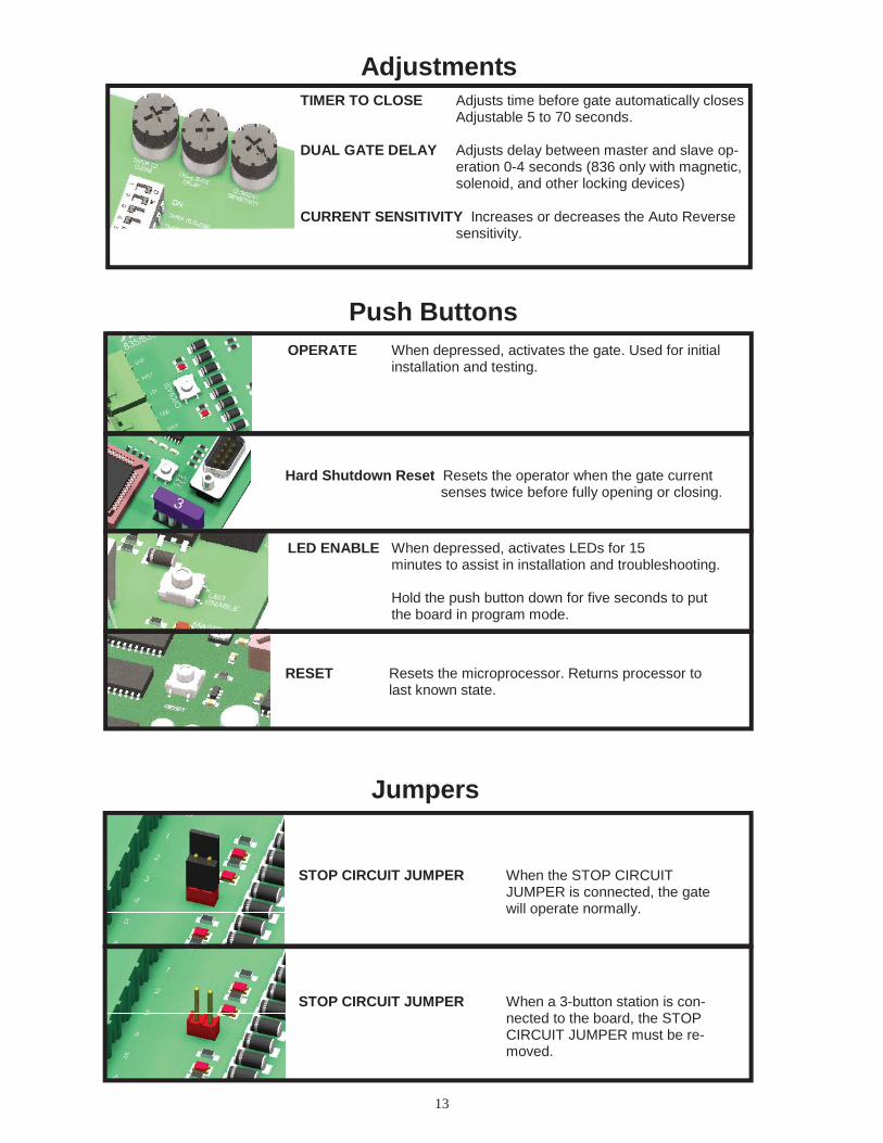
Adjustments
Push Buttons
TIMER TO CLOSE Adjusts time before gate automatically closesAdjustable 5 to 70 seconds.
DUAL GATE DELAY Adjusts delay between master and slave op-eration 0-4 seconds (836 only with magnetic,solenoid, and other locking devices)
CURRENT SENSITIVITY Increases or decreases the Auto Reversesensitivity.
LED ENABLE When depressed, activates LEDs for 15minutes to assist in installation and troubleshooting.
Hold the push button down for five seconds to putthe board in program mode.
RESET Resets the microprocessor. Returns processor tolast known state.
Jumpers
STOP CIRCUIT JUMPER When the STOP CIRCUITJUMPER is connected, the gatewill operate normally.
STOP CIRCUIT JUMPER When a 3-button station is con-nected to the board, the STOPCIRCUIT JUMPER must be re-moved.
OPERATE When depressed, activates the gate. Used for initialinstallation and testing.
Hard Shutdown Reset Resets the operator when the gate currentsenses twice before fully opening or closing.

14
Program Switches
OFF ON1 TIMER TO CLOSE Gate does not automatically close. Gate automatically closes.
2 TIMER TO CLOSE OPT. Gate automatically closes from Gate automatically closes only when completelyany position after opening. open (open limit engaged).
3 SLAVE DISABLE Enables slave side (dual gate use). Disables slave side. (single gate use)
4 SIREN DELAY Siren (optional) active when gate is Siren (optional) starts 5 seconds before gate moves.moving.
5 OPEN/CLOSE INPUT OPT. Must hold down open or close Normal operationbuttons to move gate. Gate stops Momentary open or close input runs gate to limit.when button released.
6 LOCK TYPE For 12V mechanical (solenoid) locks. For 12V magnetic locks.(+12V for 4 seconds on open cycle) (+12V when on close limit)
7 COAST ENABLE Gate will stop immediately when at Gate will coast (minimally) when it reaches limits.Open or Close limit Recommended for 7500 slide operator only.
8 FREE EXIT OPT. A free exit input will open gate from A free exit input will open gate from anyclosed position or after a close cycle position after an open or close cycle.only.
9 DUAL GATE SYNC Both gates operate at normal This feature will control the master gate to openSpeed (slave slower than or close at the same speed as the slave gate.Master).
10 SMART ACT. Off for all operators other than On for 1550 and 1650 operators only.1550 & 1650 Enables soft start & soft stop.
15
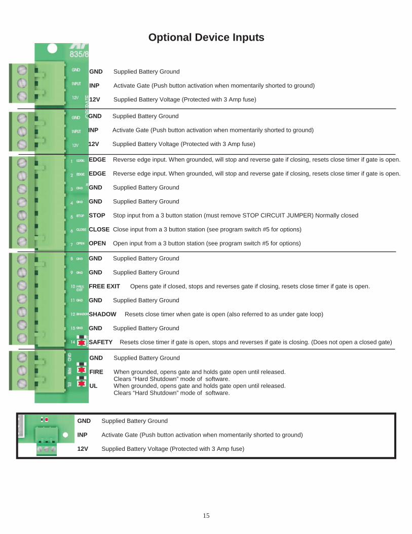
GND Supplied Battery Ground
INP Activate Gate (Push button activation when momentarily shorted to ground)
12V Supplied Battery Voltage (Protected with 3 Amp fuse)
GND Supplied Battery Ground
INP Activate Gate (Push button activation when momentarily shorted to ground)
12V Supplied Battery Voltage (Protected with 3 Amp fuse)
EDGE Reverse edge input. When grounded, will stop and reverse gate if closing, resets close timer if gate is open.
EDGE Reverse edge input. When grounded, will stop and reverse gate if closing, resets close timer if gate is open.
GND Supplied Battery Ground
GND Supplied Battery Ground
STOP Stop input from a 3 button station (must remove STOP CIRCUIT JUMPER) Normally closed
CLOSE Close input from a 3 button station (see program switch #5 for options)
OPEN Open input from a 3 button station (see program switch #5 for options)
GND Supplied Battery Ground
GND Supplied Battery Ground
FREE EXIT Opens gate if closed, stops and reverses gate if closing, resets close timer if gate is open.
GND Supplied Battery Ground
SHADOW Resets close timer when gate is open (also referred to as under gate loop)
GND Supplied Battery Ground
SAFETY Resets close timer if gate is open, stops and reverses if gate is closing. (Does not open a closed gate)
GND Supplied Battery Ground
FIRE When grounded, opens gate and holds gate open until released.Clears “Hard Shutdown” mode of software.
UL When grounded, opens gate and holds gate open until released.Clears “Hard Shutdown” mode of software.
Optional Device Inputs
GND Supplied Battery Ground
INP Activate Gate (Push button activation when momentarily shorted to ground)
12V Supplied Battery Voltage (Protected with 3 Amp fuse)

16
APOLLO Gate Operators, Inc.
911 Siren
Mount siren in an area that will produce maximum performance (additional wire may be required).
Connect the red wire to the SIREN connector on the Remote Monitor Output Connector block.
Connect the black wire to the GND connector on the Remote Monitor Output Connector block.
Red
Black
Set Program Switch # 4 as preferred:
ON - Upon activation, Siren will start for 5 seconds before gate(s) begin moving.OFF - Siren and gate(s) start immediately upon activation.
The 911 Siren is included with all Apollo ETL Gate Operators.

17
APOLLO Gate Operators RECEIVER OPTIONSDo not confuse the receiver code switches with the red program switches on the gate control board.
Never set all code switches to the same position. Transmitters must match code switches for proper operation.
If power is taken directly from battery or connected as shown below, receiver should be configured for 12VDC
Multi-Code/Digi-Code
Allstar
Lift-Master
blackgray
gray
red
white
black
red
432
1
Heddolf
black
yellow
red
white
Jumpers must beset for 12V &constant relayoption

18
Supply Voltage ……………………………………………….. 12VDC
Recommended Battery …………………………………..….. 34aH Sealed Lead Acid
Battery Charger ………………………………………………. 6 amp Automatic
Recommended Solar Panel ………………………………… 10 watt minimum with regulator
Duty Cycle …………………………………………………….. Continuous
Operating Temperature ……………………………………… –400F - +1500F
Current Draw Standby (with no accessories).……………. 10mA
Current Draw Operating …………………………………….. 2A
Arm Capacity without counter weight ……………………... 10 ft., 10 lbs. max
Arm Capacity with optional counter weight …………………. 16 ft., 15 lbs. max
Recommended Arm Material (not supplied) ……………. 1”x 4” light wood (16 ft. max)PVC (10 ft. max)Aluminum C Channel 16 ft. max
SPECIFICATIONS

19
LIMITED TWO-YEAR WARRANTYApollo Gate Operators are warranted against defects for a period of
24 months from the date of purchase, providing recommended installationprocedures are followed. This warranty is in lieu of all other warrantiesexpressed or implied (some states do not allow limitations on how long animplied warranty lasts, so this limitation may not apply to you) and shall beconsidered void if damage was due to improper installation or use,connection to improper power source, or if damage was caused by fire,flood, or lightning. The manufacturer will not be responsible for any laborcharges incurred in the removal or replacement of defective parts.
In case of failure due to defective material or workmanship during thewarranty period, the defective part will be repaired or replaced at themanufacturer’s option at no charge if returned freight prepaid. New or factoryrebuilt replacements may be used. Replacement parts are warranted for theremaining portion of the original warranty period. The manufacturer will paystandard ground freight back to the customer on the return of repaired orreplaced items in warranty.
Lighting or electrical power surges may cause damage beyond repair andare not covered in this warranty.
APOLLO Gate Operators, Inc.