Embed Size (px)
Citation preview
Apollo FireWire Software Manual
UAD Software Version 9
www.uaudio.com
H I G H - R E S O L U T I O N I N T E R F A C Ewith Realtime UAD Processing
Manual Version 190122
Apollo FireWire Software Manual Table Of Contents 2
Table Of Contents
About This Manual ................................................................................ 6For Apollo rack models connected via FireWire ..................................................... 6
Introduction ......................................................................................... 7Welcome To Apollo! ............................................................................................ 7Apollo Software Features .................................................................................... 8Apollo Documentation Overview ........................................................................ 10Apollo Software Overview .................................................................................. 12
Installation & Setup ............................................................................ 14Apollo FireWire System Requirements ................................................................ 15Installation On Windows Systems ...................................................................... 16Windows Setup ................................................................................................ 17Installation On Mac Systems ............................................................................. 18Optimizing FireWire Performance ...................................................................... 19
Working With Apollo ............................................................................ 22Apollo Setups Overview .................................................................................... 22About UAD Powered Plug-Ins Processing............................................................ 23Using Apollo as an Audio Interface .................................................................... 25Using Apollo with Console (without a DAW) ........................................................ 30Using Apollo Without A Computer ...................................................................... 31Using Apollo with a DAW (without Console) ........................................................ 32Using Apollo Concurrently with a DAW and Console ............................................. 35Virtual I/O ....................................................................................................... 37PT Mode ......................................................................................................... 39
Console Overview ................................................................................ 41What is Console? ............................................................................................. 41Console Functions ........................................................................................... 42Global Settings ................................................................................................ 42When To Use Console ....................................................................................... 43Interactions Between Console and Apollo .......................................................... 43Accessing Console ........................................................................................... 44Console Layout ................................................................................................ 45Global Window Elements .................................................................................. 47Meter Bridge Overview ...................................................................................... 48
Tip: Click any section or page number to jump directly to that page.
Apollo FireWire Software Manual Table Of Contents 3
Info Bar Overview ............................................................................................ 49Current Bank Overview ..................................................................................... 50View Column Overview ...................................................................................... 51Monitor Column Overview ................................................................................. 53Channel Strips Overview ................................................................................... 54Console Plug-In Inserts Overview ....................................................................... 56Insert Effects Overview ..................................................................................... 57Popover Windows ............................................................................................. 58Cues Overview ................................................................................................. 59Sends Overview ............................................................................................... 60Console Sessions Overview ................................................................................ 63Console Settings Overview ................................................................................ 64Keyboard Focus & Control ................................................................................. 65Adjusting Console Controls ............................................................................... 66Controls Shortcuts ........................................................................................... 66Keyboard Shortcuts .......................................................................................... 67Multiple Undo/Redo ......................................................................................... 68Apollo Model Differences .................................................................................. 68
Console Reference .............................................................................. 69Meter Bridge ................................................................................................... 69View Column ................................................................................................... 72View Options ................................................................................................... 75Info Bar .......................................................................................................... 81Channel Input Controls ..................................................................................... 86Console Plug-In Inserts .................................................................................... 89Sends Popover ................................................................................................. 90Flex Routing .................................................................................................... 92Monitor Mix Controls ........................................................................................ 94Aux Returns .................................................................................................. 100Monitor Column ............................................................................................. 103Cue Outputs Popover ...................................................................................... 107Control Room Column .................................................................................... 110Console Sessions ........................................................................................... 112Sessions Manager Popover .............................................................................. 114Window Title Bar ............................................................................................ 119Application Menus ......................................................................................... 120
Apollo FireWire Software Manual Table Of Contents 4
Console Plug-In Inserts ..................................................................... 124Inserts Display ............................................................................................... 124Signal Flow ................................................................................................... 125Unison Insert ................................................................................................ 125Insert Assign Popover ..................................................................................... 125Insert State Indicators .................................................................................... 126Insert Hover Options ...................................................................................... 126Insert Options Menu ...................................................................................... 127Channel Insert Effects .................................................................................... 128Plug-In Editor Window .................................................................................... 129Channel Strips ............................................................................................... 132Presets Manager ............................................................................................ 134Presets Manager Popover ................................................................................ 137Save Preset Popover ....................................................................................... 139
Console Settings ............................................................................... 140Console Settings Overview .............................................................................. 140Hardware Settings Panel ................................................................................ 142Display Panel ................................................................................................ 148Plug-Ins Panel ............................................................................................... 150MIDI Panel ................................................................................................... 152
Console Recall Plug-In ...................................................................... 154Console Recall Overview ................................................................................. 154Console Recall Controls .................................................................................. 155How To Use Console Recall ............................................................................. 156
Unison............................................................................................. 158What is Unison? ............................................................................................ 158Unison Features ............................................................................................ 159Unison Plug-Ins ............................................................................................. 159Activating Unison .......................................................................................... 160Unique Behavior of Unison Inserts .................................................................. 161Controlling Unison Plug-Ins with Apollo ........................................................... 162Gain Stage Mode ........................................................................................... 165Unison Load/Save Behaviors ........................................................................... 168Unison Operation Notes .................................................................................. 169
Apollo FireWire Software Manual Table Of Contents 5
Latency & Apollo .............................................................................. 171Delay Compensation with Apollo ...................................................................... 171Input Delay Compensation in Console .............................................................. 171Latency Basics .............................................................................................. 174
Multi-Unit Cascading ........................................................................ 177Multi-Unit Wiring Diagrams............................................................................. 178Multi-Unit FireWire Bandwidth ........................................................................ 180Multi-Unit Operation ...................................................................................... 181Multi-Unit Clocking ........................................................................................ 184Multi-Unit Flex Routing .................................................................................. 184Console Session Management ......................................................................... 185Multi-Unit Constraints .................................................................................... 186
Device Drivers .................................................................................. 187Apollo Drivers Overview .................................................................................. 187Driver I/O Tables ............................................................................................ 188
Glossary ........................................................................................... 201
Notices ............................................................................................ 208
Technical Support ............................................................................. 209Universal Audio Knowledge Base ..................................................................... 209YouTube Support Channel ............................................................................... 209Universal Audio Community Forums ................................................................ 209Contact Universal Audio Support ..................................................................... 209
Apollo FireWire Software Manual About This Manual 6
About This Manual
For Apollo rack models connected via FireWireThis software manual applies only to first-generation (silver) Apollo and Apollo 16 rack models with FireWire ports that are connected to the host computer system via FireWire in a single-unit or multi-unit cascading configuration with Console 2 software.
For other Apollo models
Thunderbolt connections
For all Apollo models that are connected to the computer via Thunderbolt, refer to the Apollo Thunderbolt Software Manual.
USB 3 connections
For Apollo Twin USB, refer to the Apollo Twin USB Software Manual.
About Apollo DocumentationSee the Apollo Documentation Overview for related information.
Apollo FireWire Software Manual Introduction 7
Introduction
Welcome To Apollo!
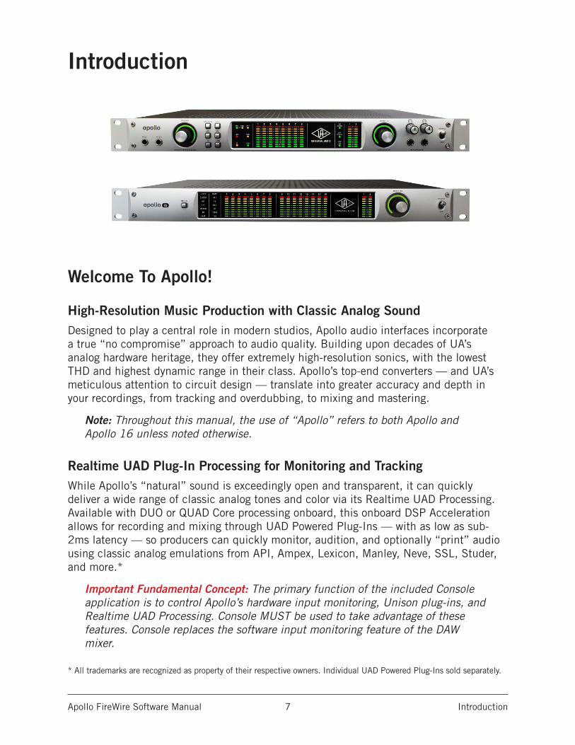
High-Resolution Music Production with Classic Analog SoundDesigned to play a central role in modern studios, Apollo audio interfaces incorporate a true “no compromise” approach to audio quality. Building upon decades of UA’s analog hardware heritage, they offer extremely high-resolution sonics, with the lowest THD and highest dynamic range in their class. Apollo’s top-end converters — and UA’s meticulous attention to circuit design — translate into greater accuracy and depth in your recordings, from tracking and overdubbing, to mixing and mastering.
Note: Throughout this manual, the use of “Apollo” refers to both Apollo and Apollo 16 unless noted otherwise.
Realtime UAD Plug-In Processing for Monitoring and TrackingWhile Apollo’s “natural” sound is exceedingly open and transparent, it can quickly deliver a wide range of classic analog tones and color via its Realtime UAD Processing. Available with DUO or QUAD Core processing onboard, this onboard DSP Acceleration allows for recording and mixing through UAD Powered Plug-Ins — with as low as sub-2ms latency — so producers can quickly monitor, audition, and optionally “print” audio using classic analog emulations from API, Ampex, Lexicon, Manley, Neve, SSL, Studer, and more.*
Important Fundamental Concept: The primary function of the included Console application is to control Apollo’s hardware input monitoring, Unison plug-ins, and Realtime UAD Processing. Console MUST be used to take advantage of these features. Console replaces the software input monitoring feature of the DAW mixer.
* All trademarks are recognized as property of their respective owners. Individual UAD Powered Plug-Ins sold separately.
Apollo FireWire Software Manual Introduction 8
Apollo Software FeaturesNote: For a list of hardware features, refer to the Apollo Hardware Manuals.
Console Application
General:
• Enables Realtime UAD Processing on Apollo inputs with indiscernible latency• Analog-style mixer for low-latency monitoring and tracking with UAD plug-ins• Remote control of Apollo hardware features and functionality• Console sessions can be saved/loaded for instant recall of any configuration• Multiple Undo/Redo for edit operations
Realtime UAD Processing:
• Up to four UAD plug-ins can be serially chained on each input and aux return• UAD insert processing can be monitored “wet” while recording wet or dry• Sub-2ms round-trip latency with four serial UAD plug-ins at 96 kHz sample rate
Channel Inputs:
• Input channels for all interface hardware inputs (except MADI with Apollo 16)
• Level, pan, solo, and mute controls on all inputs• Four plug-in insert slots per input for Realtime UAD Processing• Two stereo auxiliary sends with level and pan controls on all inputs• Virtual inputs accept any outputs from DAW• Stereo headphone sends with level and pan controls on all inputs*• Up to four stereo cue mix sends with level and pan controls on all inputs*• Adjacent input pairs can be linked for convenient stereo control• Sample rate conversion is available on S/PDIF and AES/EBU inputs*• Physical inputs can be routed to physical outputs
Monitoring:
• Stereo monitor mix bus with level, mute, solo clear, and source select controls• 2 stereo headphone buses; switchable to monitor mix and/or mirror to any output (Apollo)
• 4 stereo cue mix buses; switchable to monitor mix and/or mirror to any output (Apollo 16)
• Independent monophonic sum controls for all mix buses• S/PDIF and AES/EBU outputs can optionally mirror the post-fader monitor mix*
Auxiliary and Cue Buses:
• Two stereo auxiliary returns with independent level, mute, and mono sum controls• Four plug-in inserts per auxiliary return for Realtime UAD Processing• Auxiliary buses can be routed to main monitor mix or headphone & cue outputs*• Auxiliary & cue buses can be routed to any output*• Independent pre/post switching on each auxiliary bus
*Specific software features depend on hardware functionality not available with all Apollo models. Details within.
Apollo FireWire Software Manual Introduction 9
Metering:
• Signal level meters with peak hold and clip indicators on all inputs• Dual peak hold meters with signal peak LEDs display monitor bus levels• Input meters are globally switchable to display pre or post fader signal levels• Independently selectable peak/clip hold times and global clear clips button
Console Recall plug-in• Convenient access to Console’s monitor controls via DAW plug-in• Saves complete Apollo configurations inside DAW projects for easy recall of settings• VST, RTAS, AAX 64, and Audio Units plug-in formats
UAD Powered Plug-Ins• Award-winning audio plug-ins for monitoring, tracking, mixing, and mastering• UAD plug-ins can be used simultaneously within Console and/or DAW• All UAD plug-ins include fully-functional 14-day demo period• Complete UAD plug-ins library is available online at www.uaudio.com
UAD Meter & Control Panel application• Configures global UAD-2 and UAD Powered Plug-Ins settings• Facilitates automatic authorization of UAD plug-in licenses and UAD-2 devices• UAD-2 resource meters for DSP/Memory usage and FireWire bandwidth
Device Drivers• All hardware inputs and outputs can be individually addressed by DAW• All of Console’s mix buses can be routed to DAW inputs for recording
Apollo FireWire Software Manual Introduction 10
Apollo Documentation OverviewDocumentation for all Apollo components is extensive, so instructions are separated by areas of functionality. Each functional area has a separate manual file. An overview of each file, and how they are accessed, is provided in this section.
All manual files are in PDF format. PDF files require a free PDF reader application such as Adobe Acrobat Reader (Windows & Mac) or Preview (Mac).
Apollo Manual Files
Apollo Hardware Manuals
Each Apollo model has a unique hardware manual. The Apollo hardware manuals contain complete hardware-related details about one specific Apollo model. Included are detailed descriptions of all hardware features, controls, connectors, and specifications.
Note: Each hardware manual contains the unique Apollo model in the file name.
Apollo Software Manual
The Apollo Software Manual is the companion guide to the Apollo hardware manuals. It contains detailed information about how to configure and control all Apollo software features using the Console application, Console Settings window, and Console Recall plug-in. Refer to the Apollo Software Manual to learn how to operate the software tools and integrate Apollo’s functionality into the DAW environment.
Note: Each Apollo connection protocol (Thunderbolt, FireWire, USB) has its own unique software manual.
UAD System ManualThe UAD System Manual is the complete operation manual for Apollo’s UAD-2 functionality and applies to the entire UAD-2 product family. It contains detailed information about installing and configuring UAD devices, the UAD Meter & Control Panel application, buying optional plug-ins at the UA online store, and more. It includes everything about UAD except Apollo-specific information and individual UAD plug-in descriptions.
UAD Plug-Ins ManualThe features and functionality of all individual UAD Powered Plug-Ins is detailed in the UAD Plug-Ins Manual. Refer to that document to learn about the operation, controls, and user interface of each UAD plug-in that is developed by Universal Audio.
Direct Developer Plug-In ManualsUAD Powered Plug-Ins includes plug-ins created by our Direct Developer partners. Documentation for these 3rd-party plug-ins are separate files that are written and provided by the plug-in developers. The file names for these plug-in manuals are the same as the plug-in titles.
Apollo FireWire Software Manual Introduction 11
Accessing Installed DocumentationAny of these methods can be used to access installed documentation:
• Choose “Documentation” from the Help menu within the Console application• Click the “Product Manuals” button in the Help panel within the UAD Meter &
Control Panel application• Product manuals are also available online at help.uaudio.com
UA Website & Knowledge BaseThe Universal Audio Knowledge Base is your complete technical resource for configuring, operating, and troubleshooting UA products.
You can watch helpful support videos, search the Knowledge Base for answers, find updated technical information that may not be available in other publications, and more.
• help.uaudio.com
UAD Community ForumsThe unofficial UAD discussion forums are a valuable resource for all Universal Audio product users. This website is independently owned and operated.
• www.uadforum.com
Host DAW DocumentationEach host DAW application has its own particular methods for configuring audio interfaces and using plug-ins. Refer to the host DAW’s documentation for specific instructions about using audio interface and plug-in features within the DAW.
HyperlinksLinks to other manual sections and web pages are highlighted in blue text. Click a hyperlink to jump directly to the linked item.
Tip: Use the “back” button in the PDF reader application to return to the previous page after clicking a hyperlink.
GlossaryThis manual uses technical terms and acronyms that may be unfamiliar. Refer to the Glossary for the definitions of many of these terms.
Apollo FireWire Software Manual Introduction 12
Apollo Software OverviewApollo has several software components that comprise the complete Apollo system. A brief description of each component is provided below, along with a link to complete details about the component.
Console Application The Console application is Apollo’s primary software interface. Its main function is to control the hardware unit and its digital mixing and monitoring capabilities. The Console mixer is where Realtime UAD Processing using UAD Powered Plug-Ins is configured.
Important Fundamental Concept: The primary function of the included Console application is to control Apollo’s hardware input monitoring, Unison plug-ins, and Realtime UAD Processing. Console MUST be used to take advantage of these features. Console replaces the software input monitoring feature of the DAW mixer.
For an overview of the application, see Console Overview. For complete details, see Console Reference.
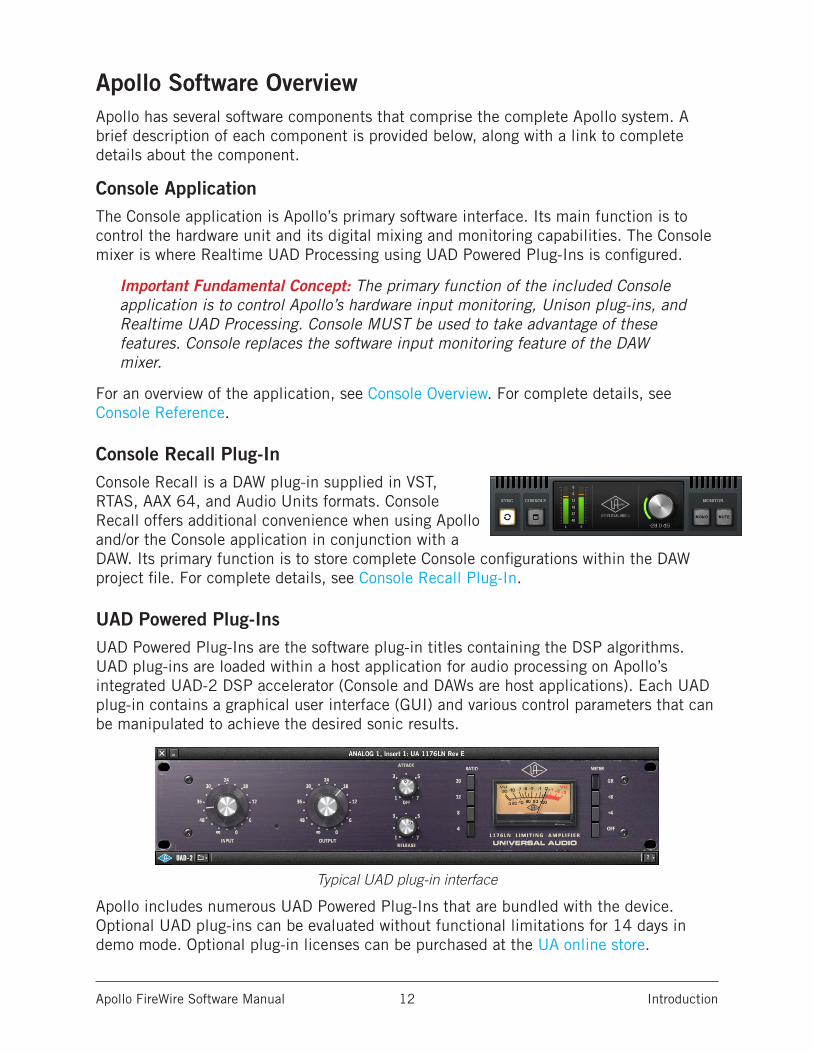
Console Recall Plug-InConsole Recall is a DAW plug-in supplied in VST, RTAS, AAX 64, and Audio Units formats. Console Recall offers additional convenience when using Apollo and/or the Console application in conjunction with a DAW. Its primary function is to store complete Console configurations within the DAW project file. For complete details, see Console Recall Plug-In.
UAD Powered Plug-InsUAD Powered Plug-Ins are the software plug-in titles containing the DSP algorithms. UAD plug-ins are loaded within a host application for audio processing on Apollo’s integrated UAD-2 DSP accelerator (Console and DAWs are host applications). Each UAD plug-in contains a graphical user interface (GUI) and various control parameters that can be manipulated to achieve the desired sonic results.
Typical UAD plug-in interface
Apollo includes numerous UAD Powered Plug-Ins that are bundled with the device. Optional UAD plug-ins can be evaluated without functional limitations for 14 days in demo mode. Optional plug-in licenses can be purchased at the UA online store.
Apollo FireWire Software Manual Introduction 13
For additional details about how UAD Powered Plug-Ins are used with Console and DAWs, see About UAD Powered Plug-Ins Processing. For general UAD plug-ins operation instructions, see the UAD System Manual. For complete details about each individual UAD Powered Plug-In, see the UAD Plug-Ins Manual.
UAD Meter & Control Panel ApplicationThe UAD Meter & Control Panel application is used to configure global functionality that pertains to all UAD-2 devices in the same system (the same application is used for all UAD-2 products). All UAD-2 global system settings are set within this application. The application also facilitates automatic authorization of UAD plug-in licenses and UAD-2 devices. The application consists of two components: The UAD Meter and the UAD Control Panels.
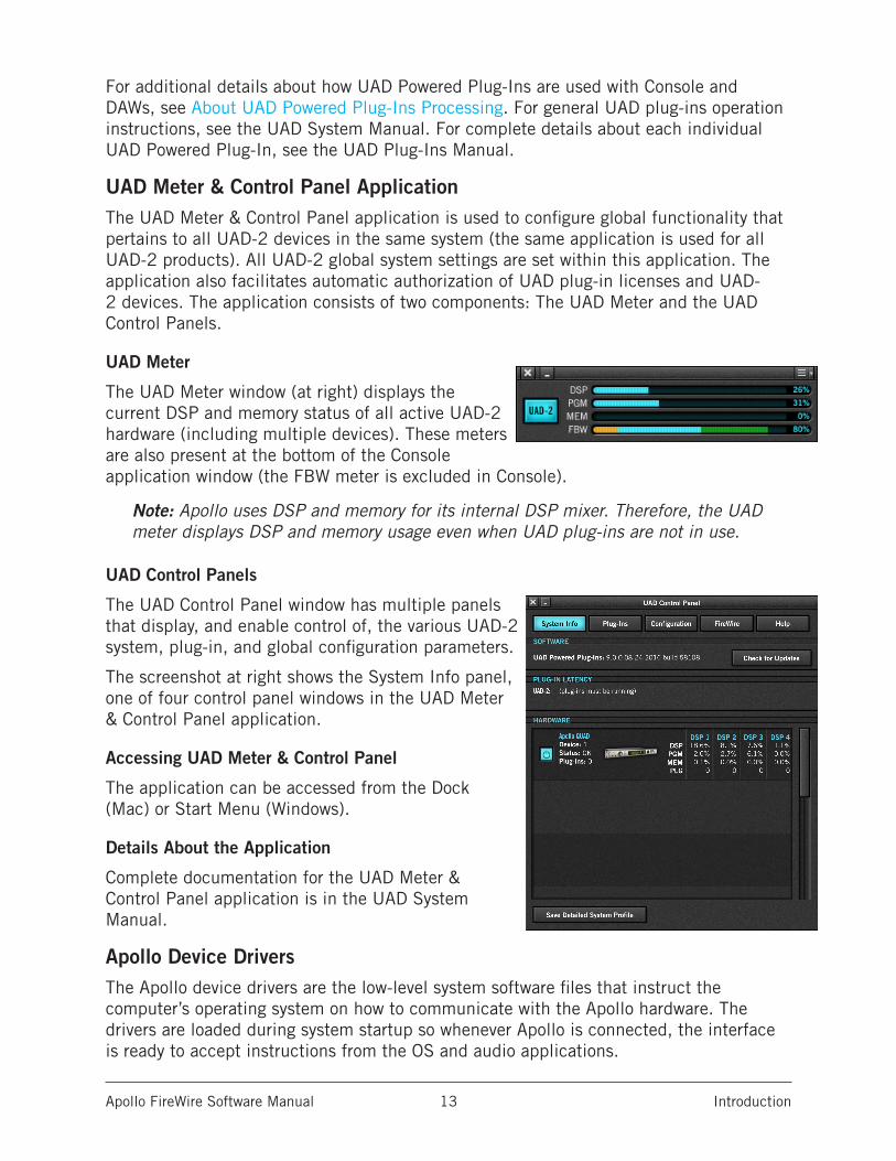
UAD Meter
The UAD Meter window (at right) displays the current DSP and memory status of all active UAD-2 hardware (including multiple devices). These meters are also present at the bottom of the Console application window (the FBW meter is excluded in Console).
Note: Apollo uses DSP and memory for its internal DSP mixer. Therefore, the UAD meter displays DSP and memory usage even when UAD plug-ins are not in use.
UAD Control Panels
The UAD Control Panel window has multiple panels that display, and enable control of, the various UAD-2 system, plug-in, and global configuration parameters.
The screenshot at right shows the System Info panel, one of four control panel windows in the UAD Meter & Control Panel application.
Accessing UAD Meter & Control Panel
The application can be accessed from the Dock (Mac) or Start Menu (Windows).
Details About the Application
Complete documentation for the UAD Meter & Control Panel application is in the UAD System Manual.
Apollo Device DriversThe Apollo device drivers are the low-level system software files that instruct the computer’s operating system on how to communicate with the Apollo hardware. The drivers are loaded during system startup so whenever Apollo is connected, the interface is ready to accept instructions from the OS and audio applications.
Apollo FireWire Software Manual Installation & Setup 14
Installation & Setup
The UAD Powered Plug-Ins software must be installed to use Apollo. The UAD installer places all the software necessary to configure and use Apollo and UAD plug-ins onto the computer’s startup drive.
Note: For hardware installation notes and wiring diagrams, refer to the Apollo Hardware Manuals.
Getting Started VideosHelpful videos are available to guide you through the installation and setup process:
• help.uaudio.com
Software UpdatesThe most recent UAD software is always recommended so you'll have access to the latest UAD plug-ins and stability updates. The most recent software is available at the UA website: www.uaudio.com/downloads
Firmware UpdatesFor optimum results, always update the firmware if prompted by the software. Follow the onscreen instructions to complete the process before attempting to use the software.
PreparationClose all open files and applications before starting the software installation procedure. The installer requires a restart after installation.
If you are updating to a newer version of Apollo software or installing additional UAD devices, it is not necessary to remove the previous UAD software or hardware from the system.
Automatic AuthorizationIf the hardware was previously registered, when the computer restarts the UAD Meter & Control Panel automatically opens and UAD plug-ins are automatically authorized in the background.
Offline AuthorizationTo authorize a UAD system that is not connected to the Internet, see the UAD System Manual.
Technical Assistance
If you need help, see the Technical Support page.
Apollo FireWire Software Manual Installation & Setup 15
Apollo FireWire System RequirementsNote: For complete compatibility information, visit help.uaudio.com
PC
• Windows 7, 8.1, or 10 (64-Bit Editions)• Compatible PCIe-to-FireWire 800 adapter card
Mac
• macOS 10.11 El Capitan, 10.12 Sierra, 10.13 High Sierra, or 10.14 Mojave• Available FireWire 800 port
All Platforms
• FireWire 800 cable (included)• Six gigabytes available storage• Internet connection to download software and authorize UAD plug-ins• Compatible VST, Audio Units, RTAS, or AAX 64 DAW application software
Apollo FireWire Software Manual Installation & Setup 16
Installation On Windows Systems
Install the PCIe to FireWire 800 Adapter Card First
Important: For optimum results, install and configure the required PCIe-to-FireWire 800 adapter card before installing the UAD software or connecting Apollo.
Connect and Power Apollo Before Installing Software
Note: For optimum results, connect and power the Apollo hardware before installing the UAD software.
Apollo FireWire Installation Procedure (Windows)1. After installing and configuring the required PCIe-to-FireWire 800 adapter card,
shut down (power off) the computer.
2. Connect Apollo to AC power with the included external power supply, then connect Apollo to the PCIe card's FW800 port on the computer with the FireWire 800 cable (included).
3. Power on Apollo with its front panel switch, then start the computer.
4. Download the latest UAD software installer: www.uaudio.com/downloads
5. Open the downloaded installer application. The installer will guide you. Be sure to restart the computer when prompted.
Note: If prompted to update the firmware, see the procedure below.
6. After restarting, the default web browser launches and connects to the UA online store. Follow the instructions in the web browser to create an account, register the hardware, and authorize bundled UAD plug-ins.
7. After registration is complete, authorize Apollo by following the instructions on the registration web pages.
8. Important! Adjust Windows system settings to optimize Apollo performance. See Windows Setup on the next page for details.
9. Important! Adjust the FireWire bandwidth setting to maximize Apollo performance. See Optimizing FireWire Performance in this chapter for details.
Firmware Update ProcedureIf prompted by the "Firmware Update" dialog window to update the Apollo firmware:
1. Click "Load" to begin the process. The "firmware is updating" window appears.
2. Wait for the "Power Off UAD Device" dialog window, which appears after the firmware is updated.
3. Power OFF Apollo, power ON Apollo. The firmware update is complete.
Apollo FireWire Software Manual Installation & Setup 17
Windows Setup
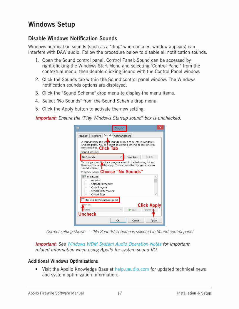
Disable Windows Notification SoundsWindows notification sounds (such as a "ding" when an alert window appears) can interfere with DAW audio. Follow the procedure below to disable all notification sounds.
1. Open the Sound control panel. Control Panel>Sound can be accessed by right-clicking the Windows Start Menu and selecting "Control Panel" from the contextual menu, then double-clicking Sound with the Control Panel window.
2. Click the Sounds tab within the Sound control panel window. The Windows notification sounds options are displayed.
3. Click the "Sound Scheme" drop menu to display the menu items.
4. Select "No Sounds" from the Sound Scheme drop menu.
5. Click the Apply button to activate the new setting.
Important: Ensure the "Play Windows Startup sound" box is unchecked.
Choose “No Sounds”
Uncheck
Click Apply
Click Tab
Correct setting shown — "No Sounds" scheme is selected in Sound control panel
Important: See Windows WDM System Audio Operation Notes for important related information when using Apollo for system sound I/O.
Additional Windows Optimizations
• Visit the Apollo Knowledge Base at help.uaudio.com for updated technical news and system optimization information.
Apollo FireWire Software Manual Installation & Setup 18
Installation On Mac Systems
Connect and Power Apollo Before Installing Software
Note: For optimum results, connect and power the Apollo hardware before installing the UAD software.
Apollo FireWire Installation Procedure (Mac)1. Shut down (power off) the computer.
2. Connect Apollo to AC power with the included external power supply, then connect Apollo to the computer with a FireWire 800 cable (included).
3. Power on Apollo with its front panel switch, then start the computer.
4. Download the latest UAD software installer: www.uaudio.com/downloads
5. Open the downloaded installer application. The installer will guide you. Be sure to restart the computer when prompted.
Note: If prompted to update the firmware, see the procedure below.
6. After restarting, the default web browser launches and connects to the UA online store. Follow the instructions in the web browser to create an account, register the hardware, and authorize bundled UAD plug-ins.
7. After registration is complete, authorize Apollo by following the instructions on the registration web pages.
8. Important! Adjust the FireWire bandwidth setting to maximize Apollo performance. See Optimizing FireWire Performance in this chapter for details.
Firmware Update ProcedureIf prompted by the "Firmware Update" dialog window to update the Apollo firmware:
1. Click "Load" to begin the process. The "firmware is updating" window appears.
2. Wait for the "Power Off UAD Device" dialog window, which appears after the firmware is updated.
3. Power OFF Apollo, then power ON Apollo. The firmware update is complete.
Apollo FireWire Software Manual Installation & Setup 19
Optimizing FireWire Performance
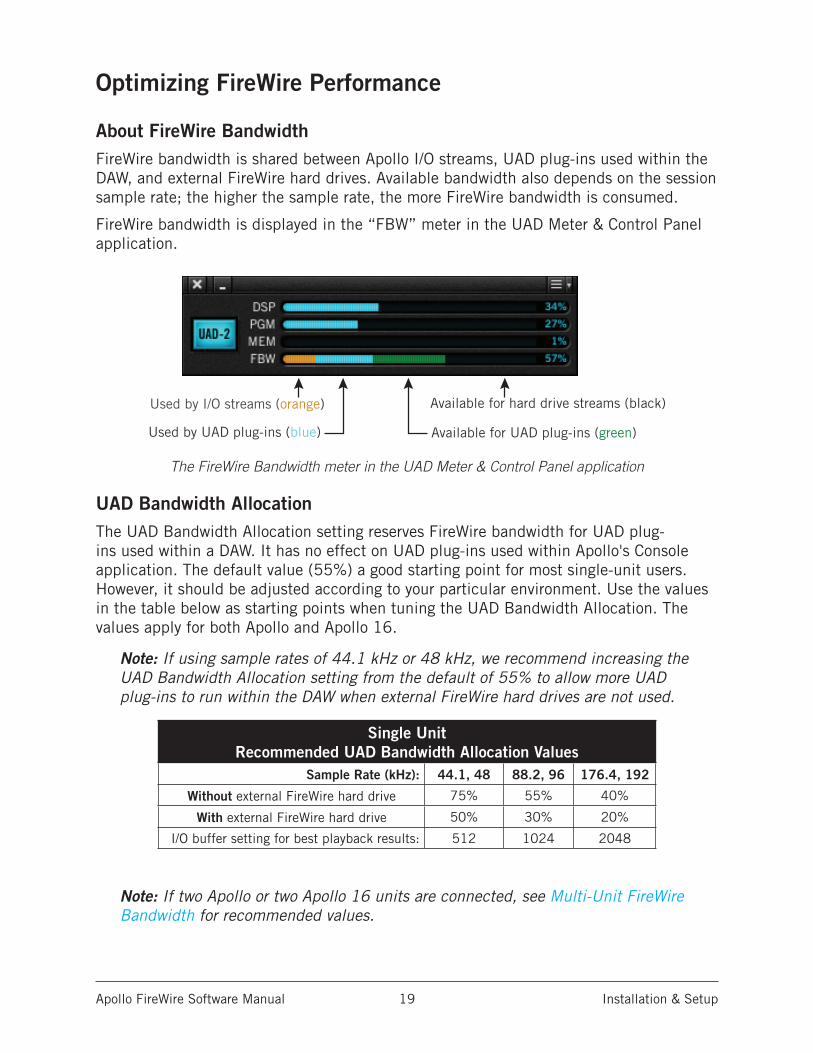
About FireWire BandwidthFireWire bandwidth is shared between Apollo I/O streams, UAD plug-ins used within the DAW, and external FireWire hard drives. Available bandwidth also depends on the session sample rate; the higher the sample rate, the more FireWire bandwidth is consumed.
FireWire bandwidth is displayed in the “FBW” meter in the UAD Meter & Control Panel application.
The FireWire Bandwidth meter in the UAD Meter & Control Panel application
UAD Bandwidth AllocationThe UAD Bandwidth Allocation setting reserves FireWire bandwidth for UAD plug-ins used within a DAW. It has no effect on UAD plug-ins used within Apollo's Console application. The default value (55%) a good starting point for most single-unit users. However, it should be adjusted according to your particular environment. Use the values in the table below as starting points when tuning the UAD Bandwidth Allocation. The values apply for both Apollo and Apollo 16.
Note: If using sample rates of 44.1 kHz or 48 kHz, we recommend increasing the UAD Bandwidth Allocation setting from the default of 55% to allow more UAD plug-ins to run within the DAW when external FireWire hard drives are not used.
Single Unit Recommended UAD Bandwidth Allocation Values
Sample Rate (kHz): 44.1, 48 88.2, 96 176.4, 192
Without external FireWire hard drive 75% 55% 40%
With external FireWire hard drive 50% 30% 20%
I/O buffer setting for best playback results: 512 1024 2048
Note: If two Apollo or two Apollo 16 units are connected, see Multi-Unit FireWire Bandwidth for recommended values.
Used by I/O streams (orange)
Used by UAD plug-ins (blue) Available for UAD plug-ins (green)
Available for hard drive streams (black)
Apollo FireWire Software Manual Installation & Setup 20
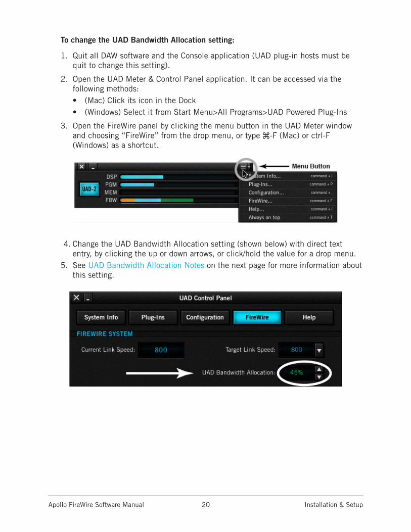
To change the UAD Bandwidth Allocation setting:
1. Quit all DAW software and the Console application (UAD plug-in hosts must be quit to change this setting).
2. Open the UAD Meter & Control Panel application. It can be accessed via the following methods:• (Mac) Click its icon in the Dock• (Windows) Select it from Start Menu>All Programs>UAD Powered Plug-Ins
3. Open the FireWire panel by clicking the menu button in the UAD Meter window and choosing “FireWire” from the drop menu, or type ⌘-F (Mac) or ctrl-F (Windows) as a shortcut.
4. Change the UAD Bandwidth Allocation setting (shown below) with direct text entry, by clicking the up or down arrows, or click/hold the value for a drop menu.
5. See UAD Bandwidth Allocation Notes on the next page for more information about this setting.
Apollo FireWire Software Manual Installation & Setup 21
UAD Bandwidth Allocation Notes• UAD Bandwidth Allocation values in the table are recommended as starting points
for FireWire bandwidth tuning. Depending on external FireWire hard drive usage (e.g., how many audio tracks are being streamed), lower values may be needed for increased FireWire hard drive loads, or higher values can be used for increased UAD plug-in counts when FireWire hard drive usage is lower. To run more UAD plug-ins within a DAW, use USB, eSATA, or internal hard drives for audio session files instead of FireWire drives.
• To avoid UAD authorization errors, set the UAD Bandwidth Allocation so the FireWire Bandwidth (FBW) gauge in the UAD Meter displays less than 100%.
• The UAD Bandwidth Allocation only applies when UAD plug-ins are used within a DAW. UAD plug-ins do not consume any FireWire bandwidth when used within Apollo's Console application, nor when connected to the host computer via the Thunderbolt Option Card.
• If the UAD Bandwidth Allocation is set such that increasing the system sample rate will cause the total bandwidth to exceed 100%, Apollo's audio I/O streams could be disabled. If this occurs, lower the UAD Bandwidth Allocation to 20% then set the sample rate to 44.1 kHz. After increasing the sample rate to the desired rate again, adjust the allocation so the total bandwidth is less than 100% at the higher sample rate.
• (Mac) FireWire performance is better on some systems versus others due to the FireWire controller chips they contain. In general, newer Mac Pro, iMac, and Mac mini systems contain a superior FireWire controller chip and will deliver better FireWire performance than MacBook Pro systems. There is no simple method to determine which controller is used.
Apollo FireWire Software Manual Working With Apollo 22
Working With Apollo
Apollo Setups OverviewApollo is a powerful and flexible audio interface that can be used in many ways. This chapter explains how to apply Apollo in various digital audio environments.
Although the exact techniques for configuring and using Apollo will vary according to needs, its application will generally fall within one of the main categories below. Each application is detailed later in this chapter.
Audio interface without DSPApollo functions like other non-DSP audio interfaces when it is used without the Console application, the Console Recall plug-in, or UAD Powered Plug-Ins. See Using Apollo as an Audio Interface for details.
Digital mixer with ConsoleApollo and Console can be used without a DAW or any other audio software, providing access to all Apollo features, its DSP mixing functionality, and Realtime UAD Processing. See Using Apollo with Console (without a DAW) for details.
Standalone use without computer Apollo can be used as a digital mixer (with limited functionality) without Console or any connection to a host computer. See Using Apollo Without A Computer for details.
With a DAW (without Console)When Apollo is used with a DAW but without the Console application (or Console Recall plug-in), the DAW controls all signal I/O routing, software monitoring, and UAD-2 DSP-accelerated UAD Powered Plug-Ins processing. See Using Apollo with a DAW (without Console) for details.
With Console and a DAWConsole is used concurrently with a DAW when low-latency monitoring and/or recording of Apollo’s inputs with (or without) Realtime UAD processing is desired. This workflow completely eliminates the I/O buffering latencies associated with software monitoring. Console’s Virtual I/O feature can also be used with the DAW to route virtual software instruments, or any other DAW outputs, into Console for Realtime UAD Processing. See Using Apollo Concurrently with a DAW and Console for details.
UAD Powered Plug-Ins: Console versus DAWThere are some fundamental differences when using UAD Powered Plug-Ins within Console or within a DAW. See About UAD Powered Plug-Ins Processing for details.
Apollo FireWire Software Manual Working With Apollo 23
About UAD Powered Plug-Ins Processing
Two Distinct Methods with ApolloApollo features two distinct methods for using UAD Powered Plug-Ins: The “Console processing method” for low-latency monitoring and tracking with Realtime UAD Processing via the Console application, and the “DAW processing method” for DSP-accelerated UAD-2 processing via VST, RTAS, AAX, and Audio Units plug-ins in DAW applications.
These two methods are not a switched mode, but instead simply depend on which application (Console or DAW) uses the UAD plug-ins. Both methods can be used simultaneously for extremely powerful and flexible signal monitoring, routing, and processing.
Console Processing Method
UAD Powered Plug-Ins run in realtime only when used within Console. Using Realtime UAD Processing in Console is optimum for artists and engineers that need to monitor and capture performances without DAW I/O buffering latency and its associated hindrances.
The special Realtime UAD Processing functionality is achieved via Apollo’s unique ultra-low latency DSP+FPGA+Console design. Although every audio interface has undetectable latency that is inherent to the A/D–D/A process, routing Apollo’s input signals through UAD Powered Plug-Ins within Console does not add to this inherent latency.
Up to four UAD plug-in instances can be inserted serially (“stacked” or “chained”) on each of Console’s analog/digital inputs and/or auxiliary buses simultaneously, without adding to the inherent I/O latency.
Note: Upsampled UAD plug-ins add latency when used within Console or a DAW. See Upsampled UAD plug-ins for more information.
Console inputs with Realtime UAD processing can be routed into the DAW via Apollo’s device drivers, and optionally recorded as either processed (wet) or unprocessed (dry) audio using the Global Insert Effects function in Console.
Important: UAD plug-ins used within Console for Realtime UAD Processing must run on the DSP within Apollo. If other UAD-2 devices are active in the same system, DSP on those devices cannot be used for Realtime UAD Processing.
Apollo FireWire Software Manual Working With Apollo 24
DAW Processing Method
When UAD Powered Plug-Ins are used within compatible VST, RTAS, AAX 64, or Audio Units host DAW applications, I/O buffering is used for plug-in processing because the data must be shuttled back and forth between the DAW and Apollo. In this scenario, the UAD-2 DSP inside Apollo behaves exactly like other UAD-2 devices such as UAD-2 Satellite and UAD-2 PCIe cards for UAD plug-in processing.
Hardware I/O buffering with a DAW adds latency that is compensated by the host DAW’s automatic delay compensation during mixing (i.e., all tracks remain time-aligned). However, at larger buffer sizes this latency makes software monitoring via the DAW mixer while tracking with UAD Powered Plug-Ins less practical. Using Apollo Concurrently with a DAW and Console eliminates this latency during tracking because software monitoring is not used — the DSP mixer inside Apollo is used for “hardware” monitoring instead.
Note: See Latency & Apollo for detailed information about latency.
Latency is not an issue during mixdown in a DAW; realtime processing is not necessary because the performances are already captured. The benefits of using Apollo’s integrated DSP acceleration during mixing include the off-loading of plug-in processing from the host computer’s CPU and the sonic rewards of UAD Powered Plug-Ins, which run exclusively on UAD-2 and Apollo platforms.
Concurrent use of UAD Plug-Ins in Console and a DAW
UAD Powered Plug-Ins can be used within Console and a DAW simultaneously. In this scenario, Apollo’s DSP resources are shared between the two applications. Realtime UAD Processing is available via Console, and I/O buffered (non-realtime) UAD processing is available via VST, RTAS, AAX 64, or Audio Units plug-ins in the DAW. See Using Apollo Concurrently with a DAW and Console for complete details.
Note: Apollo, like other UAD devices, can only load UAD Powered Plug-Ins which are specifically designed to run on UAD DSP accelerators. Host-based “native” plug-ins cannot run on the UAD DSP.
Apollo FireWire Software Manual Working With Apollo 25
Using Apollo as an Audio InterfaceApollo functions like other (non-DSP) audio interfaces when it is used without the Console application, the Console Recall plug-in, or UAD Powered Plug-Ins. Apollo’s Core Audio and ASIO drivers enable it to be used for computer audio I/O routing with any Core Audio or ASIO compliant audio software, including DAWs, music players (e.g., iTunes), system software alert sounds, and similar applications.
Accessing Apollo I/O via Core Audio and ASIOAudio is routed to and from Apollo via its Core Audio (Mac) or ASIO (Windows) device drivers. The audio software accesses Core Audio and ASIO interfaces directly via the audio settings/preference panel in the software, or it just uses the audio device set as the preference in the operating system.
Windows ASIO and WDM settings
On Windows systems, ASIO and WDM are different subsystems that are configured separately. ASIO system settings are configured in the Apollo Console Settings>Hardware panel and within the DAW preferences. WDM system settings are configured in the Sound control panel within Windows.
Note: When using Apollo for WDM system sound I/O, the sample rate of both sub-systems must be set the same rate to be heard in both subsystems. See Windows WDM System Audio Operation Notes for related information.
Apollo I/O Driver NamesEach Apollo input and output has a channel number and name provided by the Apollo drivers to Core Audio and ASIO. If an audio software application can access Core Audio / ASIO devices directly, it may be possible to designate specific inputs and/or outputs within the application.
All Apollo driver I/O numbers and names are listed in Driver I/O Tables. These values can be used to reference specific Apollo inputs or outputs by number or name if allowed by the application.
Apollo FireWire Software Manual Working With Apollo 26
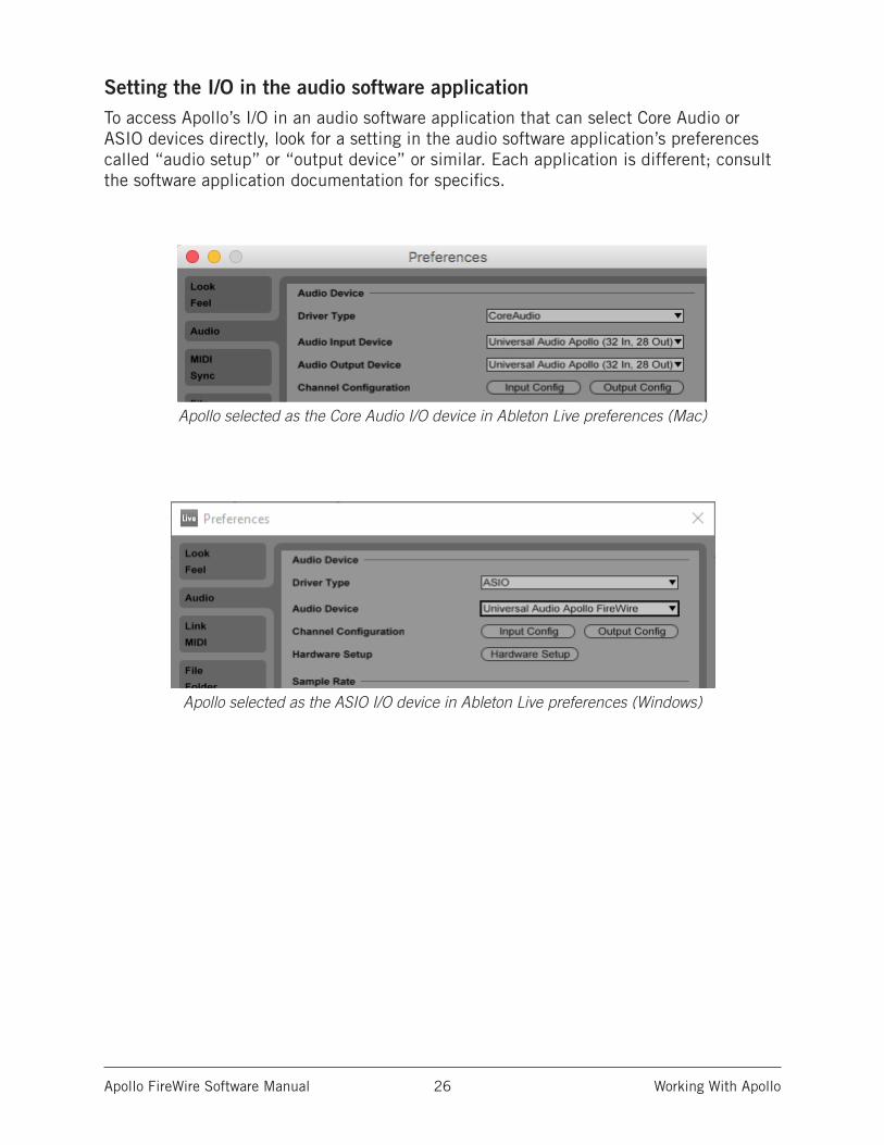
Setting the I/O in the audio software applicationTo access Apollo’s I/O in an audio software application that can select Core Audio or ASIO devices directly, look for a setting in the audio software application’s preferences called “audio setup” or “output device” or similar. Each application is different; consult the software application documentation for specifics.
Apollo selected as the Core Audio I/O device in Ableton Live preferences (Mac)
Apollo selected as the ASIO I/O device in Ableton Live preferences (Windows)
Apollo FireWire Software Manual Working With Apollo 27
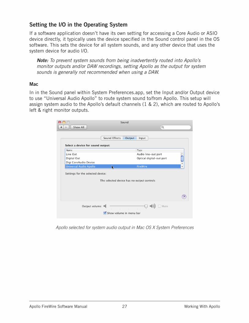
Setting the I/O in the Operating SystemIf a software application doesn’t have its own setting for accessing a Core Audio or ASIO device directly, it typically uses the device specified in the Sound control panel in the OS software. This sets the device for all system sounds, and any other device that uses the system device for audio I/O.
Note: To prevent system sounds from being inadvertently routed into Apollo’s monitor outputs and/or DAW recordings, setting Apollo as the output for system sounds is generally not recommended when using a DAW.
Mac
In in the Sound panel within System Preferences.app, set the Input and/or Output device to use “Universal Audio Apollo” to route system sound to/from Apollo. This setup will assign system audio to the Apollo’s default channels (1 & 2), which are routed to Apollo’s left & right monitor outputs.
Apollo selected for system audio output in Mac OS X System Preferences
Apollo FireWire Software Manual Working With Apollo 28
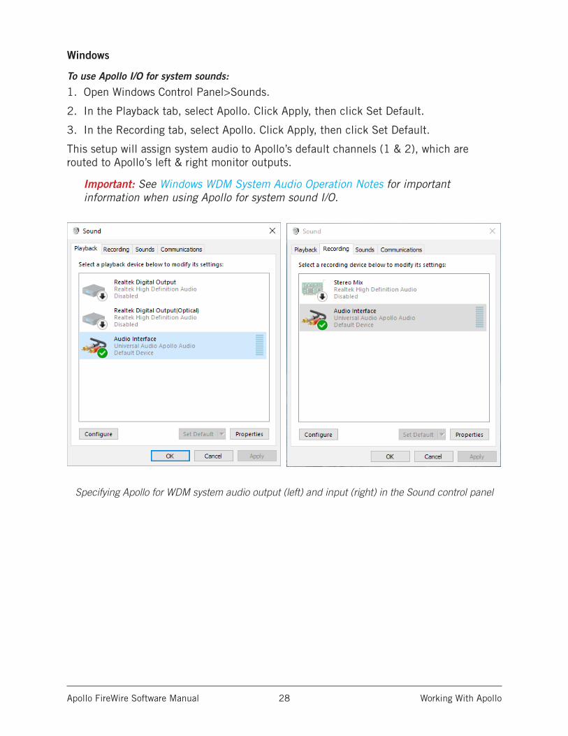
Windows
To use Apollo I/O for system sounds:
1. Open Windows Control Panel>Sounds.
2. In the Playback tab, select Apollo. Click Apply, then click Set Default.
3. In the Recording tab, select Apollo. Click Apply, then click Set Default.
This setup will assign system audio to Apollo’s default channels (1 & 2), which are routed to Apollo’s left & right monitor outputs.
Important: See Windows WDM System Audio Operation Notes for important information when using Apollo for system sound I/O.
Specifying Apollo for WDM system audio output (left) and input (right) in the Sound control panel
Apollo FireWire Software Manual Working With Apollo 29
Windows WDM System Audio Operation NotesWindows WDM system audio is used for audio input and playback in media players, web browsers, audio conference, and similar programs.
To ensure proper audio system functionality, follow these guidelines when using Apollo as the input and/or output device for Windows WDM system audio.
• Disable system notification sounds. Turn off all Windows system alert sounds us-ing the procedure detailed in the Windows Setup section.
Additional Windows Optimizations
• Visit the Apollo Knowledge Base at help.uaudio.com for updated technical news and system optimization information.
Apollo FireWire Software Manual Working With Apollo 30
Using Apollo with Console (without a DAW)Apollo and Console can be used without a DAW or any other audio software. Using Console without a DAW provides access to all Apollo functionality and simplifies the use of Apollo’s digital mixing, monitoring, and Realtime UAD processing features when a DAW’s recording and playback features are not needed.
Apollo has an internal DSP mixer for realtime mixing and monitoring of Apollo inputs, with optional Realtime UAD Processing using UAD Powered Plug-Ins. The software interface for this functionality is the Console application, but the actual mixing and signal processing occurs inside Apollo.
Using Console by itselfTo use the Console Mixer by itself for input monitoring and Realtime UAD Processing, there aren’t any special considerations; just launch Console and start using it. Full explanations of all Console features and functionality are in Console Reference.
Using Console with other audio applications
System Audio
When the OS is set to use Apollo for computer system audio (see Setting the I/O in the Operating System), the computer system audio is routed to Console’s monitor outputs and mixed with Apollo inputs (if any).
Apollo’s input levels can be adjusted with Console’s input channel faders, while the computer system’s audio level at the monitor outputs is determined by the volume settings of the audio software using the system outputs. The computer system volume level is not adjusted with Console’s input faders.
With a DAW
Digital Audio Workstations have their own audio mixer. Understanding the interactions between Console and the DAW will help to ensure an optimized workflow in this scenario. See Using Apollo Concurrently with a DAW and Console for details.
Apollo FireWire Software Manual Working With Apollo 31
Using Apollo Without A Computer
Standalone UseAlthough the Console application and/or a DAW are required to unleash the full potential of Apollo, the unit can be used as a standalone digital mixer with limited functionality without any FireWire or Thunderbolt connection to a host computer.
Console settings that are retained on power cycle
All currently active I/O assignments, signal routings, and monitor settings are saved to internal firmware before Apollo is powered down, and recalled when power is re-applied. Therefore these last-used settings are available even when a host computer is not used.
UAD plug-ins are not retained on power cycle
UAD Powered Plug-In instantiations are not retained after powering down then powering up again, because the plug-in files must be loaded from the host computer.
Standalone use with UAD plug-insIf UAD plug-ins are active when Apollo’s connection to the host computer is lost (either by disconnecting the cable or shutting down the computer), Console’s current UAD plug-in configurations remain active for Realtime UAD Processing until Apollo is powered down.
Disconnecting
Upon disconnection from the host computer, the following changes occur:
• Auxiliary buses are unmuted• Solo is deactivated on all channels• If multi-unit cascading, the clock source switches to Word Clock
Operation
After disconnecting, the following behavior applies:
• The LINK switch on Apollo’s front panel cannot be used to link or unlink stereo channels. This point only applies if the host connection was lost; the switch does operate when Apollo is powered on before connecting to a host computer.
• If channels 1 & 2 are stereo linked and an instrument is plugged into one of the Hi-Z inputs, the stereo link is unlinked, and UAD plug-in processing is bypassed on both channels. The stereo link, and UAD processing, returns when the Hi-Z input is removed.
Apollo FireWire Software Manual Working With Apollo 32
Using Apollo with a DAW (without Console)When used with a DAW but without the Console application (or Console Recall plug-in), the DAW controls all signal I/O routing, software monitoring, and DSP-accelerated UAD Powered Plug-Ins processing.
Note: Apollo, like other UAD devices, can only load UAD Powered Plug-Ins which are specifically designed to run on UAD DSP accelerators. Host-based “native” plug-ins cannot run on the UAD DSP.
Monitoring with the DAWThe primary function of Console is monitoring of Apollo’s inputs during live performance, with (or without) Realtime UAD Processing. When software monitoring is enabled in the DAW, Console’s input monitoring must be disabled to eliminate doubled signals.
Important: When the DAW’s software monitoring feature is enabled (when not using Console for input monitoring), Console’s inputs must be muted to avoid signal doubling at Apollo’s monitor outputs.
Disable input monitoring in Console when software monitoring via the DAW
If Console’s input monitoring isn’t disabled, phasing and/or doubling of the monitored signal(s) will occur, because the input signal is being heard twice – first from the low-latency DSP mix (in Console) and shortly thereafter from the higher latency software mix (in DAW).
How to disable input monitoring in Console
To disable input monitoring in Console when using software monitoring in the DAW, open Console and mute all input channels within Console. Console can then be quit.
Tip: In Console, option-click any input MUTE switch to quickly toggle the mute state of all inputs.
Using a DAW without Console is a typical workflow during mixdown, where low-latency monitoring is not required and buffering latency is not an issue because the tracks are already recorded. When recording new tracks, the DAW+Console workflow (following section) is recommended to take advantage of Apollo’s Realtime UAD Processing.
In this scenario, Apollo functions as two “separate” devices: an audio interface, and a UAD-2 DSP accelerator:
1. Audio Interface – The DAW accesses and routes Apollo’s audio interface I/O via the Core Audio or ASIO device drivers. Audio I/O latency is determined by the DAW’s I/O buffers size setting.
2. UAD-2 DSP Accelerator – The DAW controls Apollo’s internal UAD-2 DSP via UAD plug-ins in VST, RTAS, AAX, or Audio Units format that are loaded within the DAW. Buffering is used for UAD plug-ins because data from the DAW must be shuttled over FireWire or Thunderbolt to/from Apollo’s DSP.
Apollo FireWire Software Manual Working With Apollo 33
Accessing Apollo’s I/O in a DAW
Specifying the audio interface device
To access Apollo’s I/O within a DAW, the DAW’s audio engine must be configured to use Apollo as the audio interface device. Specific instructions vary by DAW; consult the DAW documentation for specifics. The I/O Buffer Size setting, which determines the overall DAW I/O latency, is usually set in the same window.
See Setting the I/O in the audio software application for examples.
I/O Complement
The specific inputs and outputs available, and their names, vary by Apollo model. For complete lists, see the Driver I/O Tables.
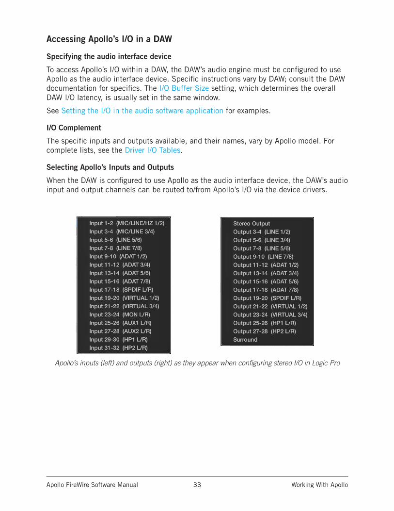
Selecting Apollo’s Inputs and Outputs
When the DAW is configured to use Apollo as the audio interface device, the DAW’s audio input and output channels can be routed to/from Apollo’s I/O via the device drivers.
Apollo’s inputs (left) and outputs (right) as they appear when configuring stereo I/O in Logic Pro
Apollo FireWire Software Manual Working With Apollo 34
Default Outputs
The main stereo outputs of a DAW usually output to channels 1 & 2 by default. Therefore, since channels 1 & 2 correspond to Apollo’s monitor outputs, the DAW’s main outputs are sent to Apollo’s monitor outputs by default. The channels used for output can usually be changed in the DAW.
Apollo I/O Driver Names
Each Apollo input and output has a channel number and name provided by the Apollo drivers. The DAW uses these numbers or names to designate the specific inputs and/or outputs within the DAW.
Numbers vs. Names
Apollo’s drivers describe all I/O channels by name and number, but what is actually displayed depends on each particular DAW. Names are not displayed by all DAWs (e.g., Ableton Live), or the driver name display mode may need to be changed in the DAW (e.g., Apple Logic Pro).
All Apollo driver I/O numbers and names are listed in the Driver I/O Tables. These values can be used to reference specific Apollo inputs or outputs by name when selecting I/O in an application that does not display the driver names.
Apollo FireWire Software Manual Working With Apollo 35
Using Apollo Concurrently with a DAW and ConsoleConsole is used concurrently with a DAW when low-latency monitoring and/or recording of Apollo’s inputs or mix buses with (or without) Realtime UAD Processing is desired. This workflow completely eliminates the I/O buffering latencies associated with software monitoring.
In this scenario, Console is used to control all input monitoring and Realtime UAD Processing when recording, and the DAW’s software monitoring feature should be disabled.
Important: To eliminate doubled signals, disable software monitoring in the DAW when Console is used to monitor Apollo’s inputs. Refer to the DAW documentation for specific instructions on how to defeat software monitoring in the DAW.
Software Monitoring versus Hardware MonitoringSoftware monitoring (listening to live inputs via the DAW mixer) has discernible latency due to audio interface I/O buffering. Hardware monitoring via an audio interface’s internal DSP mixer (e.g., Apollo’s Console application) does not have discernible latency, because the live audio is internally routed directly from the inputs to the outputs without DAW I/O buffering (see Latency Basics for detailed explanations).
Monitoring with ConsoleThe primary function of Console is monitoring of Apollo’s inputs during live performance, with (or without) Realtime UAD Processing. When used with a DAW, Console is used as a monitor mixer that functions separately from the DAW’s software monitoring mixer.
Disable Software Monitoring in the DAW when using Console
When Console is used for live input monitoring with a DAW, the DAW’s software monitoring feature should be disabled. If it isn’t, phasing and/or doubling of the monitored signal(s) will occur, because the input signal is being heard twice – first from the low-latency DSP mix (Console) and shortly thereafter from the higher latency software mix (DAW).
Important: To eliminate doubled signals, disable software monitoring in the DAW when Console is used to monitor Apollo’s inputs. Refer to the DAW documentation for specific instructions on how to defeat software monitoring in the DAW.
Apollo FireWire Software Manual Working With Apollo 36
Routing and Recording Console Inputs and Mix Buses
Recording Apollo inputs
This functionality is covered in Accessing Apollo’s I/O in a DAW.
Recording Console mix buses
Console’s monitor and send bus outputs can be routed into the DAW for recording Console’s active mixes. See Virtual I/O for details.
Recording Realtime UAD Processing
When monitoring Apollo’s inputs with Realtime UAD Processing, those inputs can be recorded with processing (wet) or without processing (dry). This function is accomplished with the Insert Effects switch. See Global Insert Effects for details.
Console with the Console Recall Plug-InThe Console Recall plug-in offers additional convenience when using Apollo and/or the Console application in conjunction with a DAW. Its primary function is to store complete Console settings within the DAW project file.
When a DAW project is loaded containing the Console Recall plug-in and the “Synchronize” function in the plug-in is enabled, the Console settings stored within the newly-loaded DAW session are sent to Console. See SYNC for details.
Latency CompensationSome latency is inevitable in complex digital audio environments such as when running a DAW with Console. Fortunately, when these applications are properly configured and operated, latency is not a deterrent because it is negligible during low-latency monitoring via Console, and automatically managed for time-alignment of recorded tracks via the DAW’s automatic delay compensation feature.
See Delay Compensation with Apollo for more information.
Recording multiple inputs simultaneously
Console’s Input Delay Compensation feature should be enabled to maintain phase alignment when monitoring and/or recording simultaneous multi-channel sources (such as a drum kit or multi-mic’d guitar amp) when Realtime UAD Processing is active in Console and some (or all) of the UAD plug-ins in Console are upsampled. See Input Delay Compensation in Console for complete details.
Latency Basics
For a complete overview of latency in a digital audio system, see Latency Basics.
Apollo FireWire Software Manual Working With Apollo 37
Virtual I/O
OverviewApollo’s device drivers carry various virtual (software only) input and output channels in addition to those directly associated with the hardware inputs and outputs. The virtual channels consist of Console’s virtual inputs, Console’s virtual outputs, and all of Apollo’s bus outputs (the main monitor mix and all channel send mix buses).
Flexible, Pristine Signal Routing
Virtual I/O facilitates highly flexible signal routing via the DAW, without needing to reach behind the gear rack for manual cable patching. Additionally, because the virtual I/O channel audio streams are in the digital domain, a pristine audio signal path is maintained without requiring additional A/D–D/A conversions.
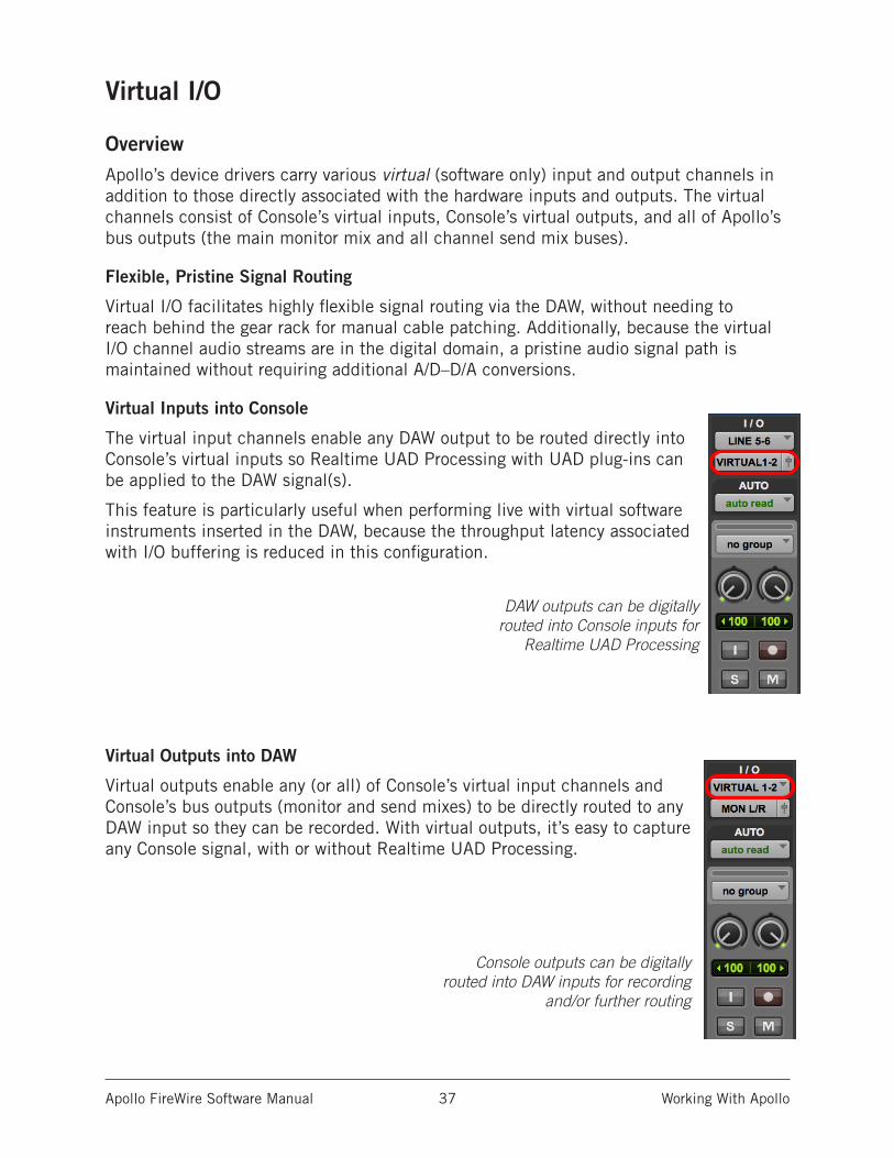
Virtual Inputs into Console
The virtual input channels enable any DAW output to be routed directly into Console’s virtual inputs so Realtime UAD Processing with UAD plug-ins can be applied to the DAW signal(s).
This feature is particularly useful when performing live with virtual software instruments inserted in the DAW, because the throughput latency associated with I/O buffering is reduced in this configuration.
DAW outputs can be digitally routed into Console inputs for
Realtime UAD Processing
Virtual Outputs into DAW
Virtual outputs enable any (or all) of Console’s virtual input channels and Console’s bus outputs (monitor and send mixes) to be directly routed to any DAW input so they can be recorded. With virtual outputs, it’s easy to capture any Console signal, with or without Realtime UAD Processing.
Console outputs can be digitally routed into DAW inputs for recording
and/or further routing
Apollo FireWire Software Manual Working With Apollo 38
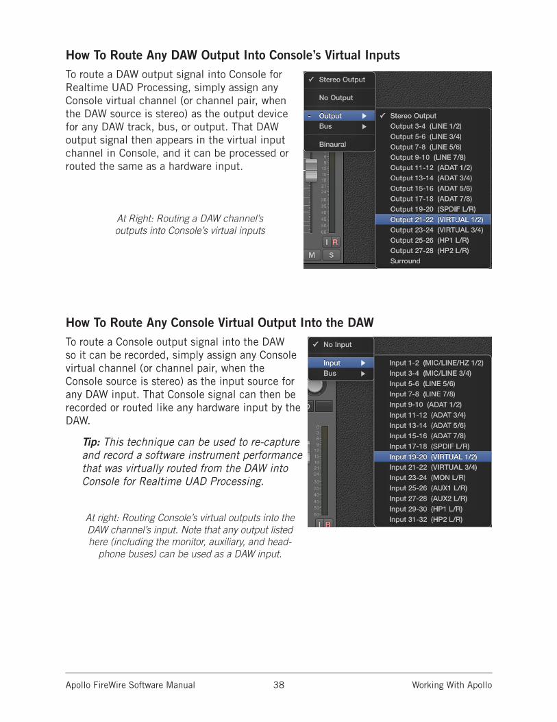
How To Route Any DAW Output Into Console’s Virtual InputsTo route a DAW output signal into Console for Realtime UAD Processing, simply assign any Console virtual channel (or channel pair, when the DAW source is stereo) as the output device for any DAW track, bus, or output. That DAW output signal then appears in the virtual input channel in Console, and it can be processed or routed the same as a hardware input.
At Right: Routing a DAW channel’s outputs into Console’s virtual inputs
How To Route Any Console Virtual Output Into the DAWTo route a Console output signal into the DAW so it can be recorded, simply assign any Console virtual channel (or channel pair, when the Console source is stereo) as the input source for any DAW input. That Console signal can then be recorded or routed like any hardware input by the DAW.
Tip: This technique can be used to re-capture and record a software instrument performance that was virtually routed from the DAW into Console for Realtime UAD Processing.
At right: Routing Console’s virtual outputs into the DAW channel’s input. Note that any output listed here (including the monitor, auxiliary, and head-
phone buses) can be used as a DAW input.
Apollo FireWire Software Manual Working With Apollo 39
PT Mode
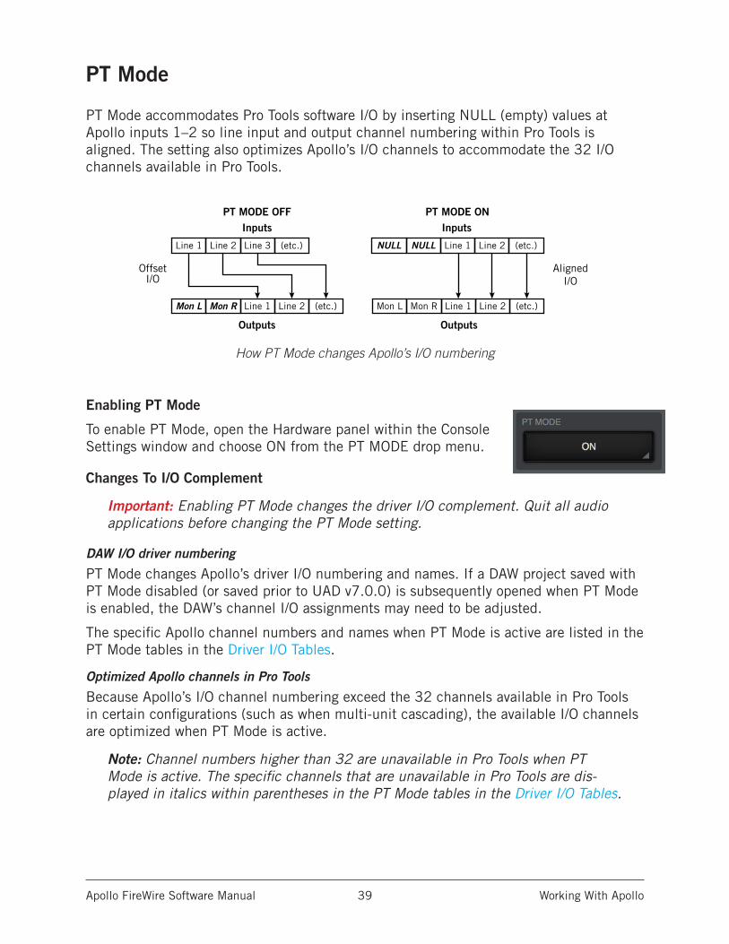
PT Mode accommodates Pro Tools software I/O by inserting NULL (empty) values at Apollo inputs 1–2 so line input and output channel numbering within Pro Tools is aligned. The setting also optimizes Apollo’s I/O channels to accommodate the 32 I/O channels available in Pro Tools.
How PT Mode changes Apollo’s I/O numbering
Enabling PT Mode
To enable PT Mode, open the Hardware panel within the Console Settings window and choose ON from the PT MODE drop menu.
Changes To I/O Complement
Important: Enabling PT Mode changes the driver I/O complement. Quit all audio applications before changing the PT Mode setting.
DAW I/O driver numbering
PT Mode changes Apollo’s driver I/O numbering and names. If a DAW project saved with PT Mode disabled (or saved prior to UAD v7.0.0) is subsequently opened when PT Mode is enabled, the DAW’s channel I/O assignments may need to be adjusted.
The specific Apollo channel numbers and names when PT Mode is active are listed in the PT Mode tables in the Driver I/O Tables.
Optimized Apollo channels in Pro Tools
Because Apollo’s I/O channel numbering exceed the 32 channels available in Pro Tools in certain configurations (such as when multi-unit cascading), the available I/O channels are optimized when PT Mode is active.
Note: Channel numbers higher than 32 are unavailable in Pro Tools when PT Mode is active. The specific channels that are unavailable in Pro Tools are dis-played in italics within parentheses in the PT Mode tables in the Driver I/O Tables.
Line 1 Line 2 Line 3 (etc.)
Mon L Mon R Line 1 Line 2 (etc.)
InputsPT MODE OFF
Outputs
OffsetI/O
PT MODE ON
Line 1 Line 2 (etc.)NULLNULL
Mon L Mon R Line 1 Line 2 (etc.)
Inputs
Outputs
AlignedI/O
Apollo FireWire Software Manual Working With Apollo 40
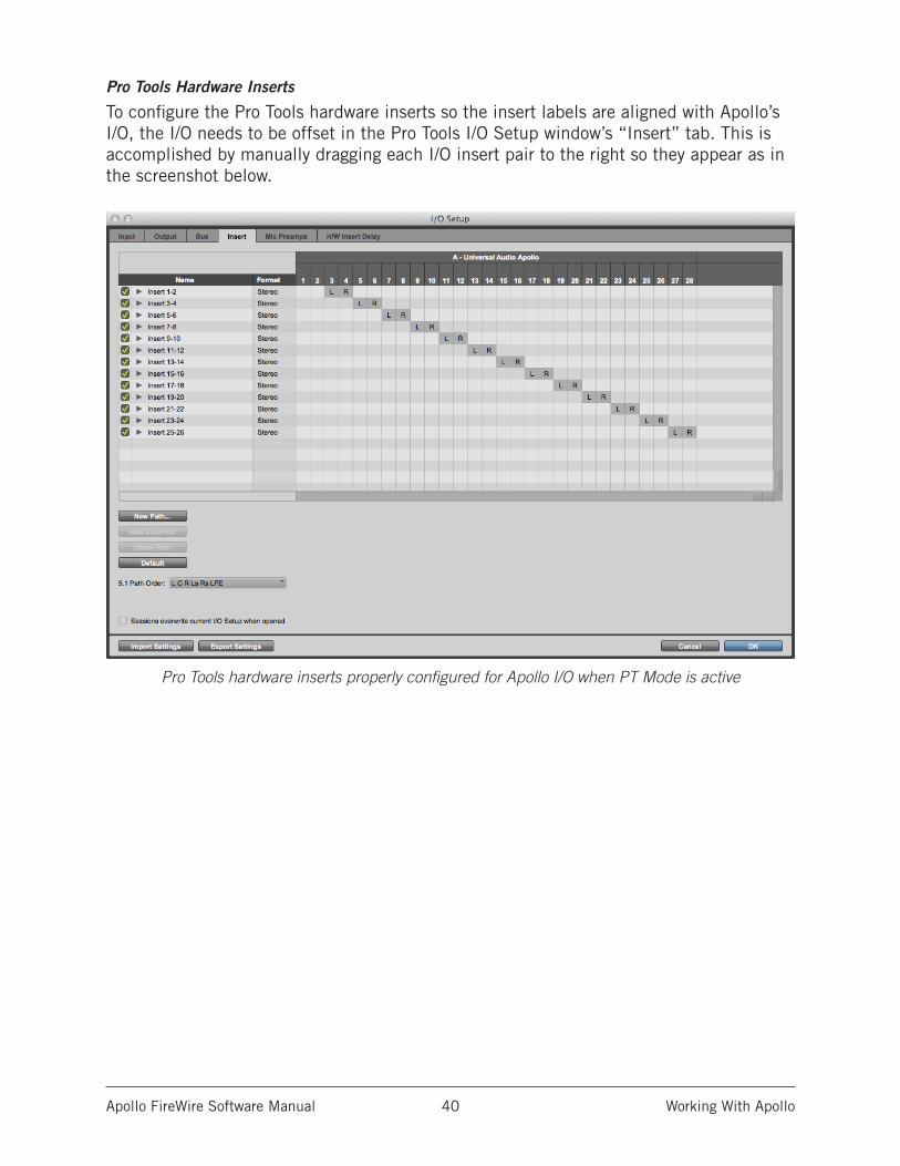
Pro Tools Hardware Inserts
To configure the Pro Tools hardware inserts so the insert labels are aligned with Apollo’s I/O, the I/O needs to be offset in the Pro Tools I/O Setup window’s “Insert” tab. This is accomplished by manually dragging each I/O insert pair to the right so they appear as in the screenshot below.
Pro Tools hardware inserts properly configured for Apollo I/O when PT Mode is active
Apollo FireWire Software Manual Console Overview 41
Console Overview
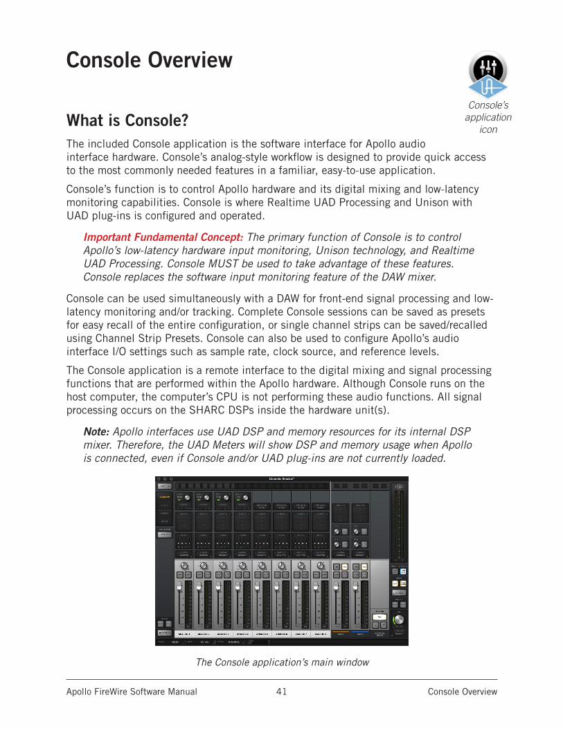
What is Console?The included Console application is the software interface for Apollo audio interface hardware. Console’s analog-style workflow is designed to provide quick access to the most commonly needed features in a familiar, easy-to-use application.
Console’s function is to control Apollo hardware and its digital mixing and low-latency monitoring capabilities. Console is where Realtime UAD Processing and Unison with UAD plug-ins is configured and operated.
Important Fundamental Concept: The primary function of Console is to control Apollo’s low-latency hardware input monitoring, Unison technology, and Realtime UAD Processing. Console MUST be used to take advantage of these features. Console replaces the software input monitoring feature of the DAW mixer.
Console can be used simultaneously with a DAW for front-end signal processing and low-latency monitoring and/or tracking. Complete Console sessions can be saved as presets for easy recall of the entire configuration, or single channel strips can be saved/recalled using Channel Strip Presets. Console can also be used to configure Apollo’s audio interface I/O settings such as sample rate, clock source, and reference levels.
The Console application is a remote interface to the digital mixing and signal processing functions that are performed within the Apollo hardware. Although Console runs on the host computer, the computer’s CPU is not performing these audio functions. All signal processing occurs on the SHARC DSPs inside the hardware unit(s).
Note: Apollo interfaces use UAD DSP and memory resources for its internal DSP mixer. Therefore, the UAD Meters will show DSP and memory usage when Apollo is connected, even if Console and/or UAD plug-ins are not currently loaded.
The Console application’s main window
Console’s application
icon
Apollo FireWire Software Manual Console Overview 42
Console FunctionsConsole enables the following functionality when used with Apollo:
• Hardware control. All of Apollo’s front panel hardware controls (except headphone volume) can be controlled using Console, facilitating easy hardware manipulation even if Apollo is installed in a location out of reach of the computer operator.
• Low-latency monitoring. Using Console eliminates the latency associated with DAW I/O buffering that makes monitoring problematic for the performer. By removing the DAW’s “software input monitoring” feature from the monitoring signal flow altogether, the need to adjust I/O buffer sizes and latency is no longer an issue.
• Realtime UAD Processing. UAD Powered Plug-Ins can be inserted into all Console inputs and/or auxiliary returns (within available DSP resources), for the ultimate latency-free sonic experience while monitoring and/or tracking live performances. All processed (or unprocessed) mix buses, including the monitor, auxiliary, and cue buses, can be optionally routed into the DAW for recording.
• Unison. Apollo’s Unison™ technology gives you the tone of the world’s most sought-after tube and solid state mic preamps — including their all-important impedance, gain stage “sweet spots,” and component-level circuit behaviors.
• Send/Return Auxiliary buses. Console has two pre/post stereo aux buses, with independent send levels per input, for grouped signal processing (conserving UAD DSP resources) or routing to alternate hardware outputs or the DAW.
• Flexible, independent monitor mixing and tracking. Two stereo headphone mix buses (Apollo) or four stereo cue mix buses (Apollo 16) with per-input sends ensure individual performers can hear “more me” if desired.
• Flexible signal routing. Using Console, any hardware input can be routed to any hardware output. Additionally, all headphone (Apollo) and cue (Apollo 16) mix buses can be mirrored to any hardware output.
• Session management. Complete Console configurations can be saved and loaded to/from disk as presets, for convenient and unlimited session management. Sessions can also be stored within the DAW project using the Console Recall plug-in.
Global SettingsParameters within Console Settings are available for configuring various global behaviors:
• Hardware. Global interface settings such as sample rate, clock source, reference levels, and digital output mirroring.
• Software. Global software settings for Console such as metering and plug-in window behaviors.
Apollo FireWire Software Manual Console Overview 43
When To Use ConsoleThe Console application can be used without a DAW, simultaneously in conjunction with a DAW, or not at all. These scenarios are covered in greater detail in Working With Apollo.
Console without DAW. Console can be used by itself without the use of a DAW or any other audio software. Using Console without a DAW provides access to all Apollo functionality and simplifies the use of Apollo’s digital mixing, monitoring, and Realtime UAD Processing features when a DAW’s recording and playback features are not needed.
Console with DAW. Console is used at the same time as a DAW when low-latency monitoring and/or recording of Apollo’s inputs with (or without) Realtime UAD Processing is desired. In this scenario, Console is used as a “front end” to control input monitoring when recording, and the DAW’s software input monitoring feature is disabled. This workflow completely eliminates the I/O buffering latencies associated with using software monitoring via the DAW.
Important: To eliminate doubled signals, software monitoring in the DAW must be disabled when Console is used for input monitoring. Conversely, Console inputs must be muted if the DAW’s software monitoring feature is enabled.
UAD plug-ins can be used within Console and a DAW simultaneously. In this scenario, Apollo’s DSP resources are shared between the two applications. Realtime UAD Processing is available via Console, and buffered (non-realtime) UAD processing is available via VST, RTAS, AAX 64, or Audio Units plug-ins within the DAW. See UAD Powered Plug-Ins: Console versus DAW for more details about this scenario.
Tip: Console can be opened or quit at any time, whether or not a DAW is already running. Console’s settings and UAD plug-ins remain active after the application is quit.
Interactions Between Console and Apollo Console’s settings mirror the Apollo hardware. Changes made to one are also made on the other, and vice versa. If changes are made to Console when Apollo is not connected, then Apollo is subsequently connected, the Console settings are sent to the hardware.
Important: If Console is launched after changes are made to Apollo using the front panel hardware controls, the current Console settings will overwrite the changes made using the hardware controls.
Apollo FireWire Software Manual Console Overview 44
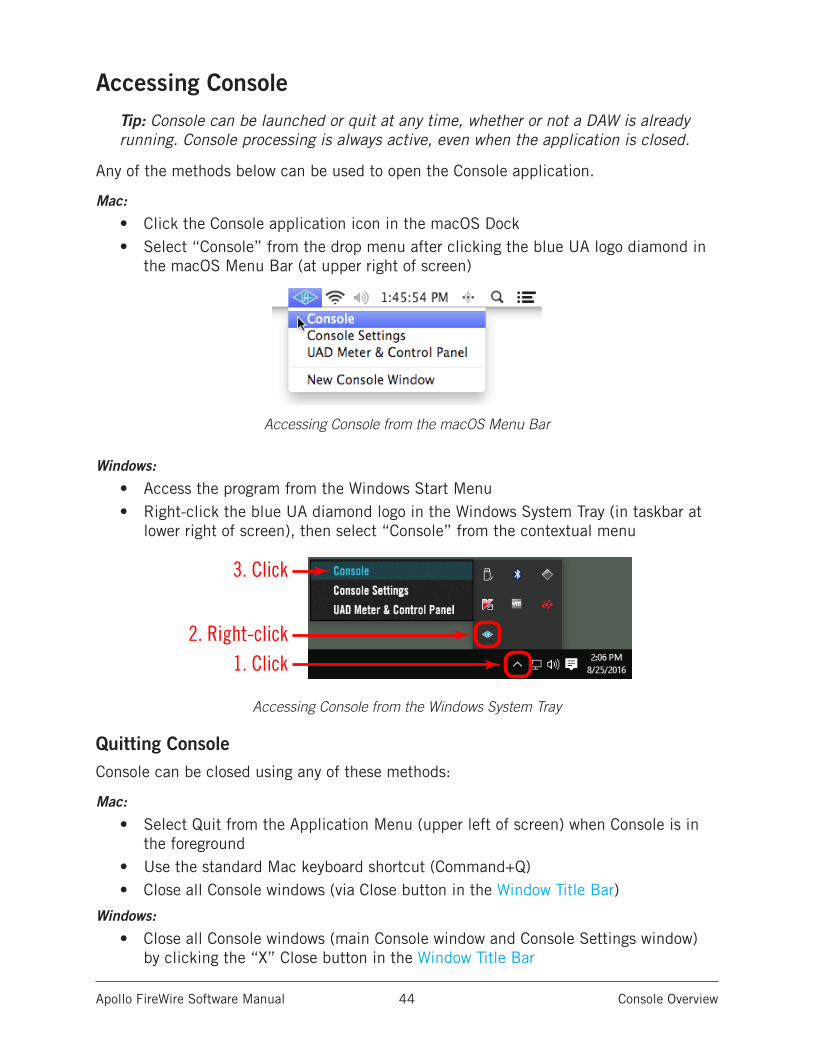
Accessing ConsoleTip: Console can be launched or quit at any time, whether or not a DAW is already running. Console processing is always active, even when the application is closed.
Any of the methods below can be used to open the Console application.
Mac:
• Click the Console application icon in the macOS Dock• Select “Console” from the drop menu after clicking the blue UA logo diamond in
the macOS Menu Bar (at upper right of screen)
Accessing Console from the macOS Menu Bar
Windows:
• Access the program from the Windows Start Menu • Right-click the blue UA diamond logo in the Windows System Tray (in taskbar at
lower right of screen), then select “Console” from the contextual menu
Accessing Console from the Windows System Tray
Quitting Console Console can be closed using any of these methods:
Mac:
• Select Quit from the Application Menu (upper left of screen) when Console is in the foreground
• Use the standard Mac keyboard shortcut (Command+Q)• Close all Console windows (via Close button in the Window Title Bar)
Windows:
• Close all Console windows (main Console window and Console Settings window) by clicking the “X” Close button in the Window Title Bar
1. Click2. Right-click
3. Click
Apollo FireWire Software Manual Console Overview 45
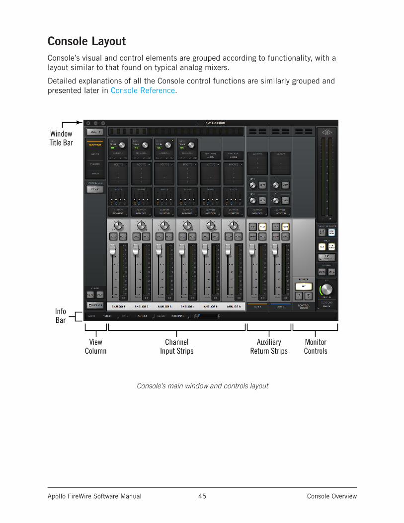
Console LayoutConsole’s visual and control elements are grouped according to functionality, with a layout similar to that found on typical analog mixers.
Detailed explanations of all the Console control functions are similarly grouped and presented later in Console Reference.
Console’s main window and controls layout
ChannelInput Strips
InfoBar
AuxiliaryReturn Strips
ViewColumn
WindowTitle Bar
MonitorControls
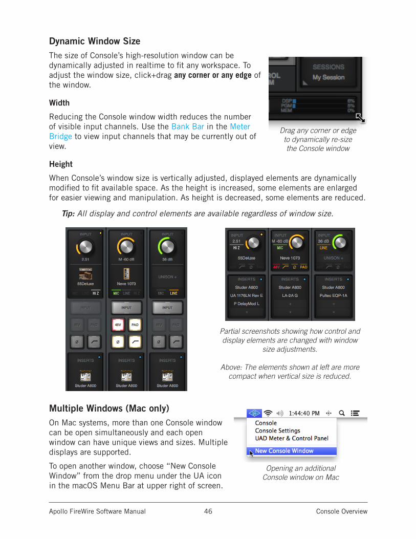
Apollo FireWire Software Manual Console Overview 46
Dynamic Window SizeThe size of Console’s high-resolution window can be dynamically adjusted in realtime to fit any workspace. To adjust the window size, click+drag any corner or any edge of the window.
Width
Reducing the Console window width reduces the number of visible input channels. Use the Bank Bar in the Meter Bridge to view input channels that may be currently out of view.
Height
When Console’s window size is vertically adjusted, displayed elements are dynamically modified to fit available space. As the height is increased, some elements are enlarged for easier viewing and manipulation. As height is decreased, some elements are reduced.
Tip: All display and control elements are available regardless of window size.
Multiple Windows (Mac only)On Mac systems, more than one Console window can be open simultaneously and each open window can have unique views and sizes. Multiple displays are supported.
To open another window, choose “New Console Window” from the drop menu under the UA icon in the macOS Menu Bar at upper right of screen.
Drag any corner or edge to dynamically re-size the Console window
Partial screenshots showing how control and display elements are changed with window
size adjustments.
Above: The elements shown at left are more compact when vertical size is reduced.
Opening an additional Console window on Mac
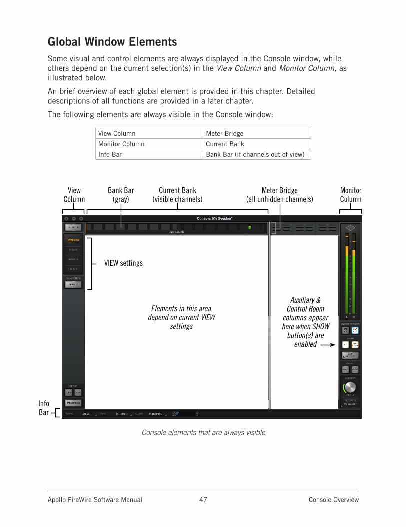
Apollo FireWire Software Manual Console Overview 47
Global Window ElementsSome visual and control elements are always displayed in the Console window, while others depend on the current selection(s) in the View Column and Monitor Column, as illustrated below.
An brief overview of each global element is provided in this chapter. Detailed descriptions of all functions are provided in a later chapter.
The following elements are always visible in the Console window:
View Column Meter Bridge
Monitor Column Current Bank
Info Bar Bank Bar (if channels out of view)
Console elements that are always visible
View Column
Monitor Column
Current Bank(visible channels)
Bank Bar(gray)
Meter Bridge(all unhidden channels)
InfoBar
Elements in this area depend on current VIEW
settings
VIEW settings
Auxiliary &Control Room
columns appear here when SHOW
button(s) are enabled
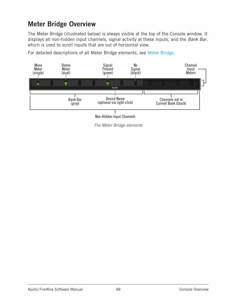
Apollo FireWire Software Manual Console Overview 48
Meter Bridge OverviewThe Meter Bridge (illustrated below) is always visible at the top of the Console window. It displays all non-hidden input channels, signal activity at these inputs, and the Bank Bar, which is used to scroll inputs that are out of horizontal view.
For detailed descriptions of all Meter Bridge elements, see Meter Bridge.
The Meter Bridge elements
StereoMeter(dual)
SignalPresent(green)
NoSignal(black)
MonoMeter
(single)
Channel Input
Meters
Bank Bar(gray)
Channels not inCurrent Bank (black)
Device Name(optional via right-click)
Non-Hidden Input Channels
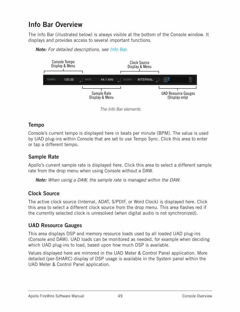
Apollo FireWire Software Manual Console Overview 49
Info Bar OverviewThe Info Bar (illustrated below) is always visible at the bottom of the Console window. It displays and provides access to several important functions.
Note: For detailed descriptions, see Info Bar.
The Info Bar elements
TempoConsole’s current tempo is displayed here in beats per minute (BPM). The value is used by UAD plug-ins within Console that are set to use Tempo Sync. Click this area to enter or tap a different tempo.
Sample RateApollo’s current sample rate is displayed here. Click this area to select a different sample rate from the drop menu when using Console without a DAW.
Note: When using a DAW, the sample rate is managed within the DAW.
Clock SourceThe active clock source (Internal, ADAT, S/PDIF, or Word Clock) is displayed here. Click this area to select a different clock source from the drop menu. This area flashes red if the currently selected clock is unresolved (when digital audio is not synchronized).
UAD Resource GaugesThis area displays DSP and memory resource loads used by all loaded UAD plug-ins (Console and DAW). UAD loads can be monitored as needed, for example when deciding which UAD plug-ins to load, based upon how much DSP is available.
Values displayed here are mirrored in the UAD Meter & Control Panel application. More detailed (per-SHARC) display of DSP usage is available in the System panel within the UAD Meter & Control Panel application.
Console TempoDisplay & Menu
Sample RateDisplay & Menu
Clock SourceDisplay & Menu
UAD Resource Gauges(Display only)
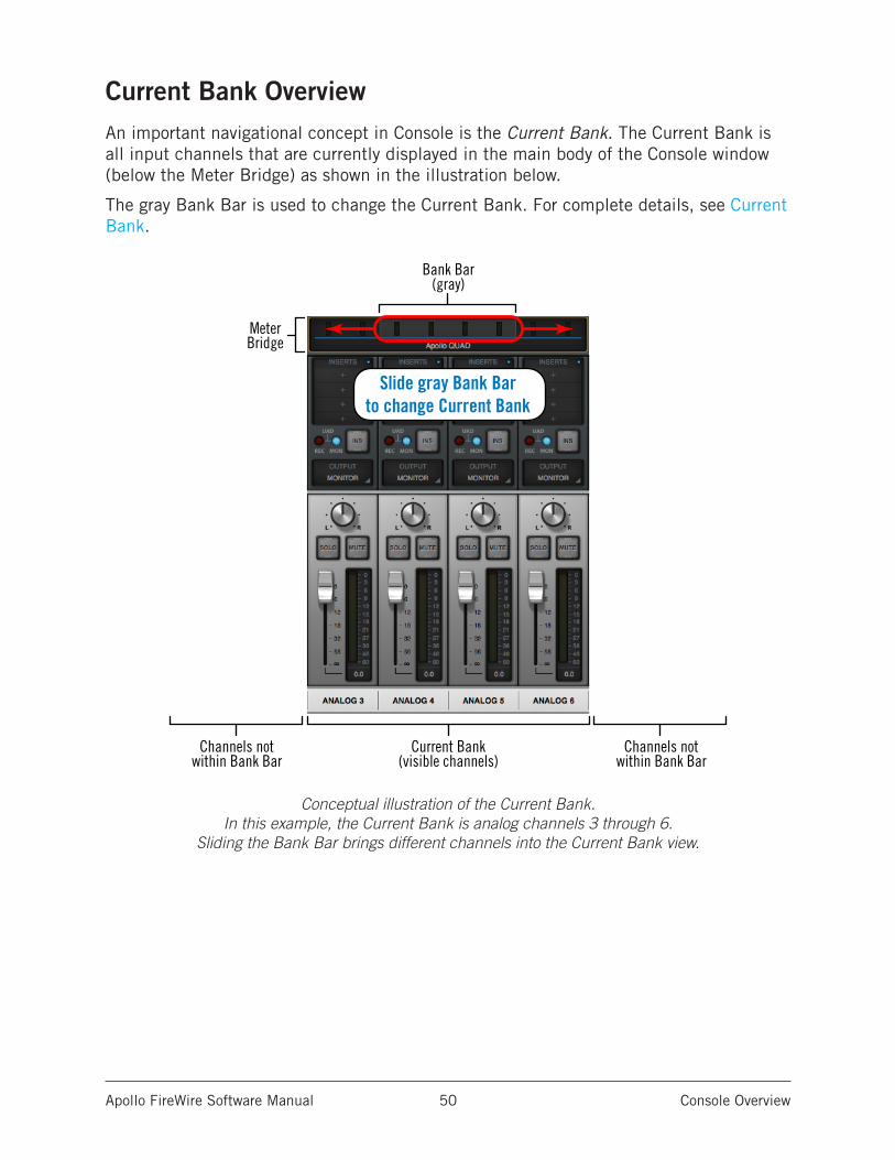
Apollo FireWire Software Manual Console Overview 50
Current Bank OverviewAn important navigational concept in Console is the Current Bank. The Current Bank is all input channels that are currently displayed in the main body of the Console window (below the Meter Bridge) as shown in the illustration below.
The gray Bank Bar is used to change the Current Bank. For complete details, see Current Bank.
Conceptual illustration of the Current Bank. In this example, the Current Bank is analog channels 3 through 6.
Sliding the Bank Bar brings different channels into the Current Bank view.
Slide gray Bank Barto change Current Bank
Bank Bar(gray)
Current Bank(visible channels)
Channels notwithin Bank Bar
Channels notwithin Bank Bar
MeterBridge
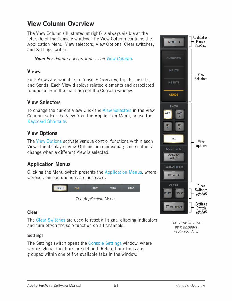
Apollo FireWire Software Manual Console Overview 51
View Column OverviewThe View Column (illustrated at right) is always visible at the left side of the Console window. The View Column contains the Application Menu, View selectors, View Options, Clear switches, and Settings switch.
Note: For detailed descriptions, see View Column.
ViewsFour Views are available in Console: Overview, Inputs, Inserts, and Sends. Each View displays related elements and associated functionality in the main area of the Console window.
View SelectorsTo change the current View: Click the View Selectors in the View Column, select the View from the Application Menu, or use the Keyboard Shortcuts.
View OptionsThe View Options activate various control functions within each View. The displayed View Options are contextual; some options change when a different View is selected.
Application MenusClicking the Menu switch presents the Application Menus, where various Console functions are accessed.
The Application Menus
Clear
The Clear Switches are used to reset all signal clipping indicators and turn off/on the solo function on all channels.
Settings
The Settings switch opens the Console Settings window, where various global functions are defined. Related functions are grouped within one of five available tabs in the window.
ViewSelectors
ApplicationMenus(global)
ViewOptions
ClearSwitches(global)
Settings Switch(global)
The View Column
as it appears in Sends View
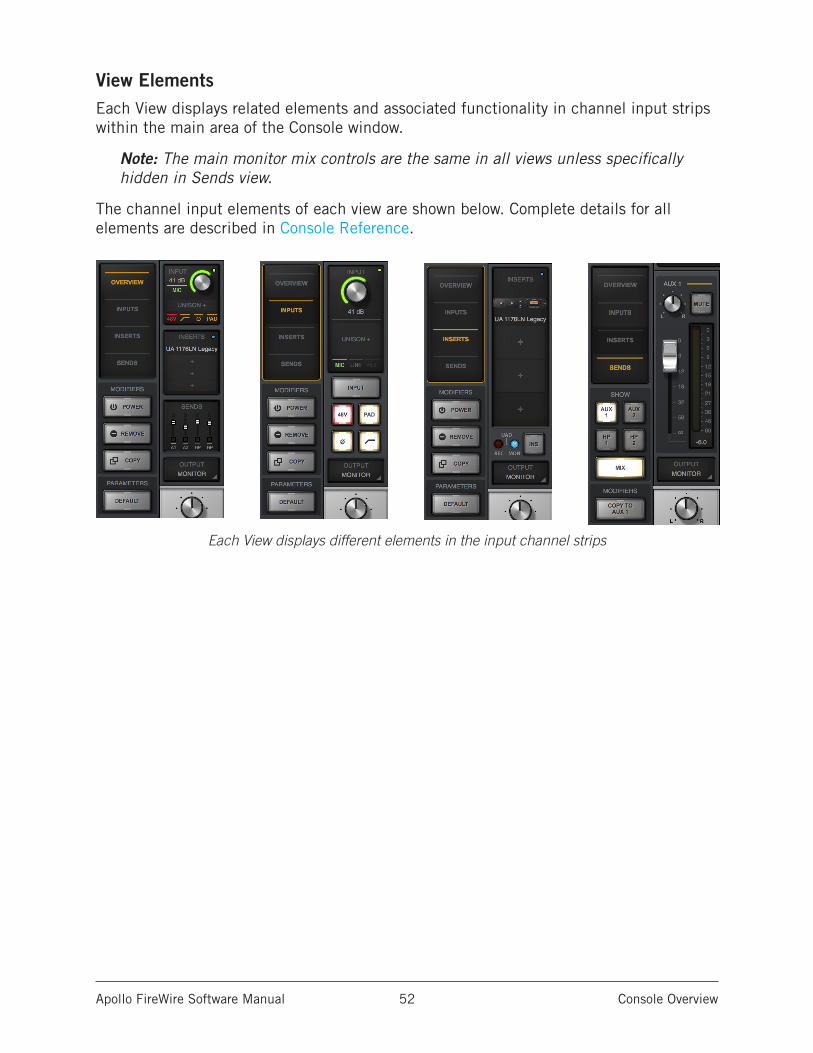
Apollo FireWire Software Manual Console Overview 52
View ElementsEach View displays related elements and associated functionality in channel input strips within the main area of the Console window.
Note: The main monitor mix controls are the same in all views unless specifically hidden in Sends view.
The channel input elements of each view are shown below. Complete details for all elements are described in Console Reference.
Each View displays different elements in the input channel strips
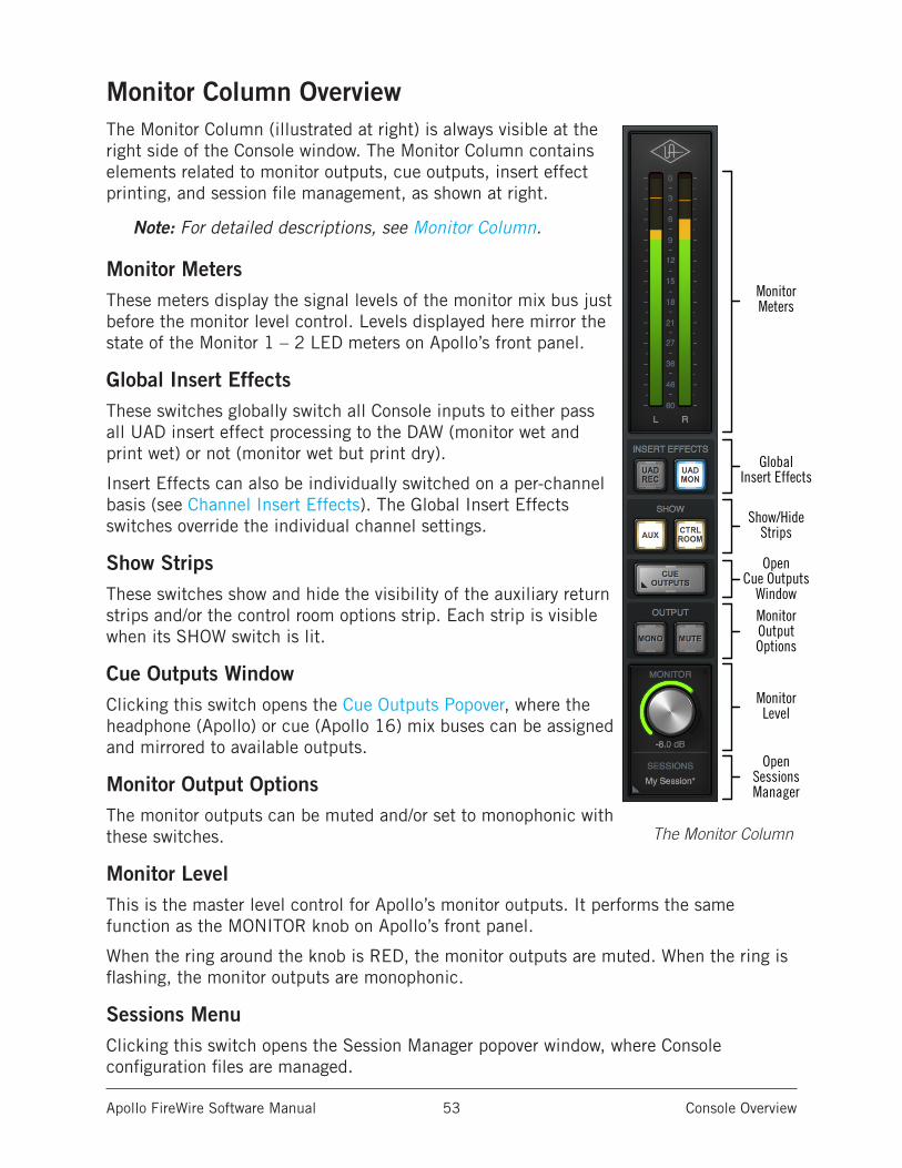
Apollo FireWire Software Manual Console Overview 53
Monitor Column OverviewThe Monitor Column (illustrated at right) is always visible at the right side of the Console window. The Monitor Column contains elements related to monitor outputs, cue outputs, insert effect printing, and session file management, as shown at right.
Note: For detailed descriptions, see Monitor Column.
Monitor MetersThese meters display the signal levels of the monitor mix bus just before the monitor level control. Levels displayed here mirror the state of the Monitor 1 – 2 LED meters on Apollo’s front panel.
Global Insert EffectsThese switches globally switch all Console inputs to either pass all UAD insert effect processing to the DAW (monitor wet and print wet) or not (monitor wet but print dry).
Insert Effects can also be individually switched on a per-channel basis (see Channel Insert Effects). The Global Insert Effects switches override the individual channel settings.
Show StripsThese switches show and hide the visibility of the auxiliary return strips and/or the control room options strip. Each strip is visible when its SHOW switch is lit.
Cue Outputs WindowClicking this switch opens the Cue Outputs Popover, where the headphone (Apollo) or cue (Apollo 16) mix buses can be assigned and mirrored to available outputs.
Monitor Output OptionsThe monitor outputs can be muted and/or set to monophonic with these switches.
Monitor LevelThis is the master level control for Apollo’s monitor outputs. It performs the same function as the MONITOR knob on Apollo’s front panel.
When the ring around the knob is RED, the monitor outputs are muted. When the ring is flashing, the monitor outputs are monophonic.
Sessions MenuClicking this switch opens the Session Manager popover window, where Console configuration files are managed.
GlobalInsert Effects
Show/HideStrips
MonitorMeters
OpenCue Outputs
WindowMonitorOutputOptions
MonitorLevel
OpenSessionsManager
The Monitor Column
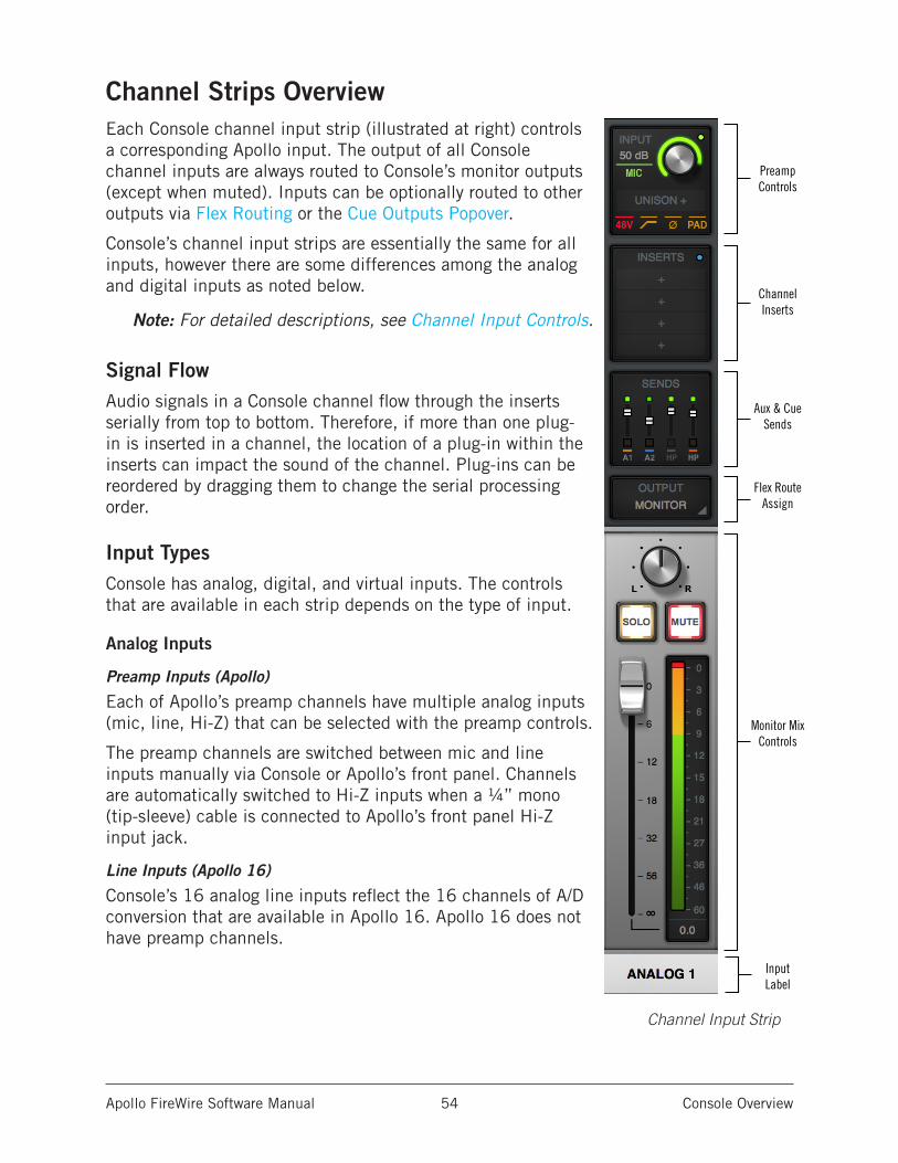
Apollo FireWire Software Manual Console Overview 54
Channel Strips OverviewEach Console channel input strip (illustrated at right) controls a corresponding Apollo input. The output of all Console channel inputs are always routed to Console’s monitor outputs (except when muted). Inputs can be optionally routed to other outputs via Flex Routing or the Cue Outputs Popover.
Console’s channel input strips are essentially the same for all inputs, however there are some differences among the analog and digital inputs as noted below.
Note: For detailed descriptions, see Channel Input Controls.
Signal FlowAudio signals in a Console channel flow through the inserts serially from top to bottom. Therefore, if more than one plug-in is inserted in a channel, the location of a plug-in within the inserts can impact the sound of the channel. Plug-ins can be reordered by dragging them to change the serial processing order.
Input TypesConsole has analog, digital, and virtual inputs. The controls that are available in each strip depends on the type of input.
Analog Inputs
Preamp Inputs (Apollo)
Each of Apollo’s preamp channels have multiple analog inputs (mic, line, Hi-Z) that can be selected with the preamp controls.
The preamp channels are switched between mic and line inputs manually via Console or Apollo’s front panel. Channels are automatically switched to Hi-Z inputs when a ¼” mono (tip-sleeve) cable is connected to Apollo’s front panel Hi-Z input jack.
Line Inputs (Apollo 16)
Console’s 16 analog line inputs reflect the 16 channels of A/D conversion that are available in Apollo 16. Apollo 16 does not have preamp channels.
PreampControls
ChannelInserts
Aux & CueSends
Flex RouteAssign
Monitor MixControls
InputLabel
Channel Input Strip
Apollo FireWire Software Manual Console Overview 55
Digital Inputs
Apollo
Console’s eight ADAT and two S/PDIF (stereo left and right) inputs work just like the analog inputs, except they don’t have the extra preamp and reference level settings that are only available on the analog inputs.
Apollo 16
Console has two AES/EBU inputs (left and right). MADI inputs are not available in Console.
Virtual Inputs
The virtual input channels in Console do not reflect Apollo’s hardware inputs. Instead, they receive digital signals from DAW outputs via Apollo’s device drivers, enabling Realtime UAD Processing on any DAW output. This feature is especially useful when playing virtual software instruments live through UAD plug-ins because it reduces I/O buffering latency. For complete details about this feature, see Virtual I/O.
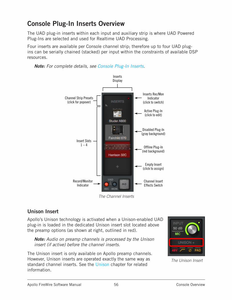
Apollo FireWire Software Manual Console Overview 56
Console Plug-In Inserts OverviewThe UAD plug-in inserts within each input and auxiliary strip is where UAD Powered Plug-Ins are selected and used for Realtime UAD Processing.
Four inserts are available per Console channel strip; therefore up to four UAD plug-ins can be serially chained (stacked) per input within the constraints of available DSP resources.
Note: For complete details, see Console Plug-In Inserts.
The Channel Inserts
Unison InsertApollo’s Unison technology is activated when a Unison-enabled UAD plug-in is loaded in the dedicated Unison insert slot located above the preamp options (as shown at right, outlined in red).
Note: Audio on preamp channels is processed by the Unison insert (if active) before the channel inserts.
The Unison insert is only available on Apollo preamp channels. However, Unison inserts are operated exactly the same way as standard channel inserts. See the Unison chapter for related information.
Inserts Rec/MonIndicator
(click to switch)
Record/MonitorIndicator
Channel Strip Presets(click for popover)
Insert Slots1 – 4
Disabled Plug-In(gray background)
Empty Insert(click to assign)
Channel InsertEffects Switch
Offline Plug-In(red background)
Active Plug-In(click to edit)
InsertsDisplay
The Unison Insert
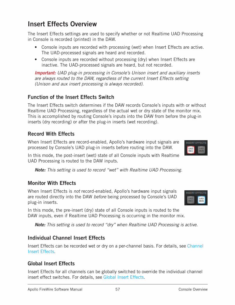
Apollo FireWire Software Manual Console Overview 57
Insert Effects OverviewThe Insert Effects settings are used to specify whether or not Realtime UAD Processing in Console is recorded (printed) in the DAW.
• Console inputs are recorded with processing (wet) when Insert Effects are active. The UAD-processed signals are heard and recorded.
• Console inputs are recorded without processing (dry) when Insert Effects are inactive. The UAD-processed signals are heard, but not recorded.
Important: UAD plug-in processing in Console’s Unison insert and auxiliary inserts are always routed to the DAW, regardless of the current Insert Effects setting (Unison and aux insert processing is always recorded).
Function of the Insert Effects SwitchThe Insert Effects switch determines if the DAW records Console’s inputs with or without Realtime UAD Processing, regardless of the actual wet or dry state of the monitor mix. This is accomplished by routing Console’s inputs into the DAW from before the plug-in inserts (dry recording) or after the plug-in inserts (wet recording).
Record With EffectsWhen Insert Effects are record-enabled, Apollo’s hardware input signals are processed by Console’s UAD plug-in inserts before routing into the DAW.
In this mode, the post-insert (wet) state of all Console inputs with Realtime UAD Processing is routed to the DAW inputs.
Note: This setting is used to record “wet” with Realtime UAD Processing.
Monitor With EffectsWhen Insert Effects is not record-enabled, Apollo’s hardware input signals are routed directly into the DAW before being processed by Console’s UAD plug-in inserts.
In this mode, the pre-insert (dry) state of all Console inputs is routed to the DAW inputs, even if Realtime UAD Processing is occurring in the monitor mix.
Note: This setting is used to record “dry” when Realtime UAD Processing is active.
Individual Channel Insert EffectsInsert Effects can be recorded wet or dry on a per-channel basis. For details, see Channel Insert Effects.
Global Insert EffectsInsert Effects for all channels can be globally switched to override the individual channel insert effect switches. For details, see Global Insert Effects.
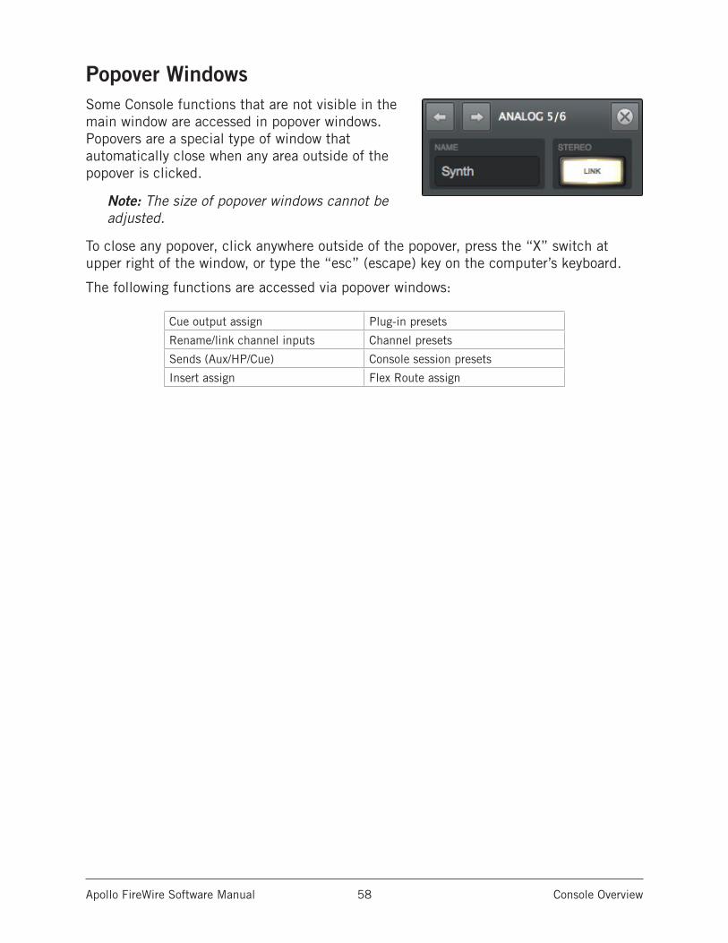
Apollo FireWire Software Manual Console Overview 58
Popover WindowsSome Console functions that are not visible in the main window are accessed in popover windows. Popovers are a special type of window that automatically close when any area outside of the popover is clicked.
Note: The size of popover windows cannot be adjusted.
To close any popover, click anywhere outside of the popover, press the “X” switch at upper right of the window, or type the “esc” (escape) key on the computer’s keyboard.
The following functions are accessed via popover windows:
Cue output assign Plug-in presets
Rename/link channel inputs Channel presets
Sends (Aux/HP/Cue) Console session presets
Insert assign Flex Route assign
Apollo FireWire Software Manual Console Overview 59
Cues OverviewThe cue mix buses are used to create unique mixes that are separate from the main monitor mix. Cues are typically used for performers that want to hear a headphone mix that is different from the main monitor mix, sending separate mixes to other rooms or audio equipment, and similar applications.
In addition to the main monitor stereo mix bus and the two auxiliary stereo mix buses, Apollo features stereo cue mix buses that can be used for a variety of signal routing purposes.
Cue LabelsThe available cue mix buses and labels vary per Apollo device model, as described below.
Apollo – The two available cues are labeled HP1 and HP2 respectively.
Apollo 16 – The four available cues are labeled CUE 1, CUE 2, CUE 3, and CUE 4 respectively.
Cue ComponentsThe complete cue system is comprised of the cue mix buses, the cue sends, and the cue outputs.
Cue Mix Buses – A cue mix bus is the summed stereo mix of individual audio signals. Signals are routed into the cue mix buses via the cue send controls, and returned from the cue mix bus via the cue outputs controls.
Cue Sends – The cue sends adjust the individual channel signals going into the cue mix bus. Each input channel and aux return contains individual level, pan,* and mute controls for each active cue mix bus. All cue sends are pre-fader and pre-mute so they are not affected by adjustments to the main monitor mix.
*Note: If two input channels are stereo-linked, the cue sends on the stereo pair cannot be panned. Sends for stereo channels are hard-panned left and right.
Cue Outputs – Cue mix buses are returned via the Cue Outputs window, which is a matrix for routing the cues to Apollo’s available hardware outputs.
Cue Monitoring – Available cue outputs also can be selected as a source for the main monitor outs via the Monitor Source Select buttons, enabling any cue mix bus to be heard in the main monitor speakers.
Apollo FireWire Software Manual Console Overview 60
Sends OverviewApollo has five mix buses and Apollo 16 has seven mix buses that are configured and adjusted within Console.
The stereo buses are used for the monitor, auxiliary, and cue mixes. Each Apollo input has independent level, pan, and mute controls for each of the stereo mix buses.
Stereo Mix BusesIn addition to the main monitor mix, the following stereo mix buses are available:
Auxiliary
The two aux buses are typically used for shared effect processing (to reduce UAD resource usage) for realtime monitoring with time-based effects such as reverb and/or delay. The aux mixes are adjusted via each input’s two aux send controls.
By default, the aux sends are post-fader and post-mute. The aux sends can be switched to be pre-fader and pre-mute. The Aux Pre / Aux Post function switch for each aux is located in its respective auxiliary bus return strip.
Cues
The cue buses are for creating mixes that are different from the main monitor mix. Cues are typically used for performers that want to hear a headphone mix that is different from the main monitor mix, or for routing individual channels or mixes to other equipment.
The cue mixes are adjusted via the cue sends on each input and aux strip. All cue sends are pre-fader and pre-mute so they are not affected by adjustments to the main monitor mix.
Mix Bus ReturnsThe stereo mix bus returns are used to route the mix to available outputs.
Auxiliary
The aux mixes are routed to the aux return strips. Cue sends are available on the aux returns for routing aux effects to the cue mix buses.
See Aux Returns for details.
Cues
The cue mixes are heard via the selections in the monitor controls section. Cues are routed to available Apollo outputs via a matrix in the Cue Outputs window. The Monitor outputs can be switched to output any cue mix instead of the monitor mix.
For cue return details, see Cue Outputs Popover.
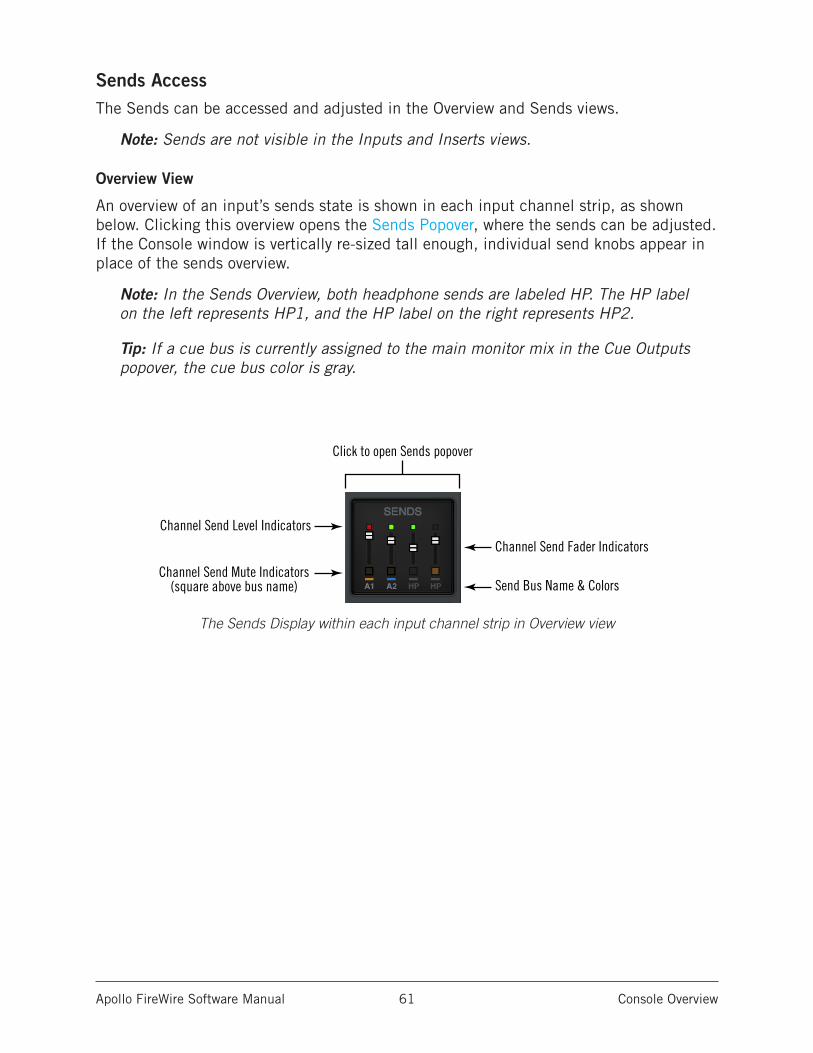
Apollo FireWire Software Manual Console Overview 61
Sends AccessThe Sends can be accessed and adjusted in the Overview and Sends views.
Note: Sends are not visible in the Inputs and Inserts views.
Overview View
An overview of an input’s sends state is shown in each input channel strip, as shown below. Clicking this overview opens the Sends Popover, where the sends can be adjusted. If the Console window is vertically re-sized tall enough, individual send knobs appear in place of the sends overview.
Note: In the Sends Overview, both headphone sends are labeled HP. The HP label on the left represents HP1, and the HP label on the right represents HP2.
Tip: If a cue bus is currently assigned to the main monitor mix in the Cue Outputs popover, the cue bus color is gray.
The Sends Display within each input channel strip in Overview view
Channel Send Level Indicators
Channel Send Fader Indicators
Send Bus Name & ColorsChannel Send Mute Indicators
(square above bus name)
Click to open Sends popover
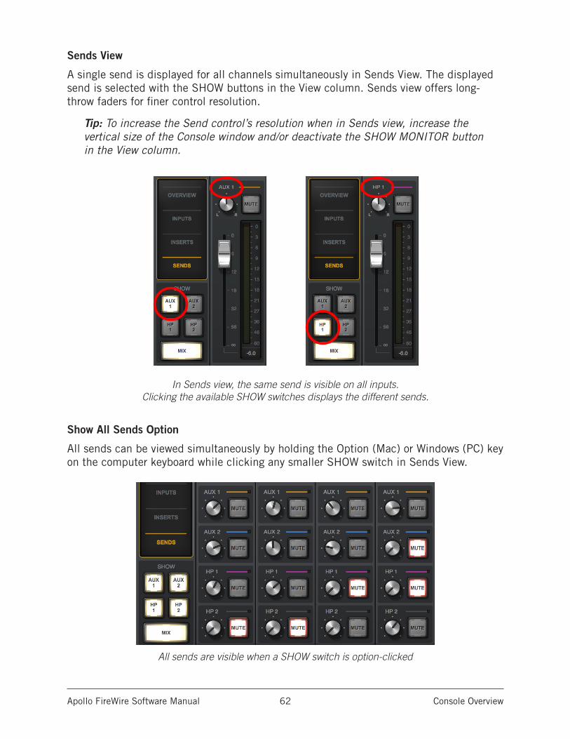
Apollo FireWire Software Manual Console Overview 62
Sends View
A single send is displayed for all channels simultaneously in Sends View. The displayed send is selected with the SHOW buttons in the View column. Sends view offers long-throw faders for finer control resolution.
Tip: To increase the Send control’s resolution when in Sends view, increase the vertical size of the Console window and/or deactivate the SHOW MONITOR button in the View column.
In Sends view, the same send is visible on all inputs. Clicking the available SHOW switches displays the different sends.
Show All Sends Option
All sends can be viewed simultaneously by holding the Option (Mac) or Windows (PC) key on the computer keyboard while clicking any smaller SHOW switch in Sends View.
All sends are visible when a SHOW switch is option-clicked
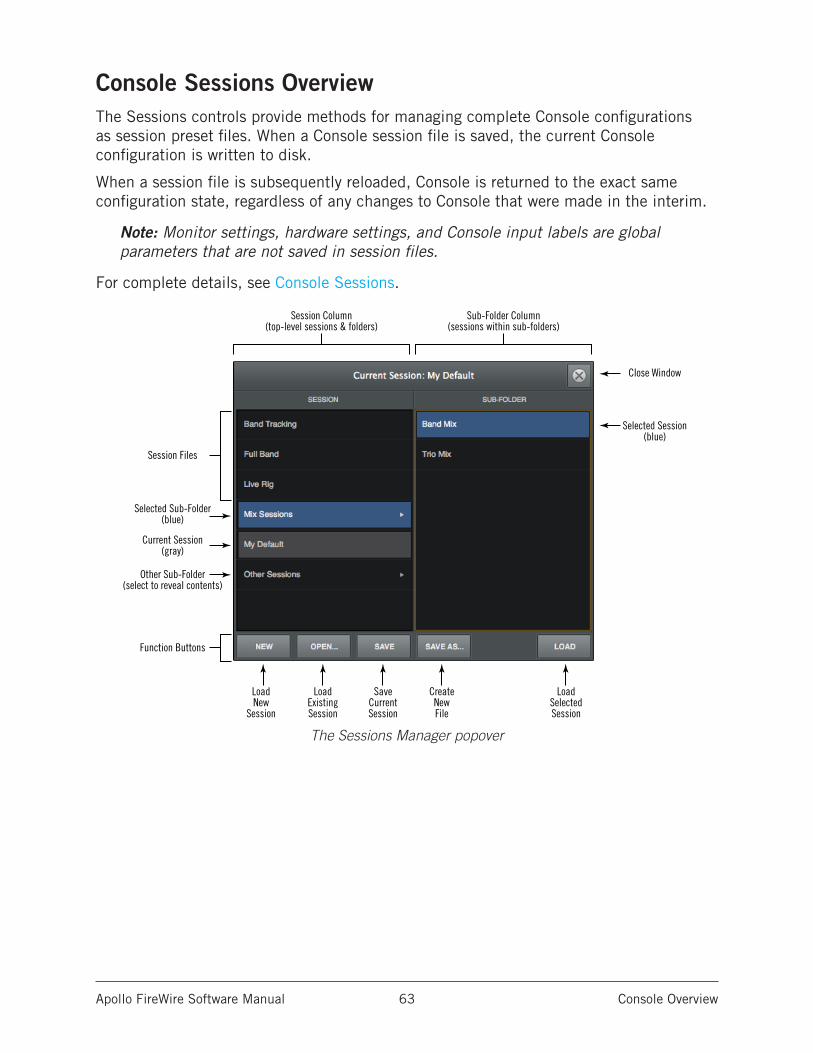
Apollo FireWire Software Manual Console Overview 63
Console Sessions OverviewThe Sessions controls provide methods for managing complete Console configurations as session preset files. When a Console session file is saved, the current Console configuration is written to disk.
When a session file is subsequently reloaded, Console is returned to the exact same configuration state, regardless of any changes to Console that were made in the interim.
Note: Monitor settings, hardware settings, and Console input labels are global parameters that are not saved in session files.
For complete details, see Console Sessions.
The Sessions Manager popover
Close Window
Selected Session(blue)
Session Files
Current Session(gray)
Selected Sub-Folder(blue)
Other Sub-Folder(select to reveal contents)
LoadNew
Session
Session Column(top-level sessions & folders)
Sub-Folder Column(sessions within sub-folders)
LoadExistingSession
SaveCurrentSession
CreateNewFile
LoadSelectedSession
Function Buttons
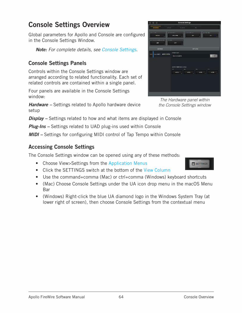
Apollo FireWire Software Manual Console Overview 64
Console Settings OverviewGlobal parameters for Apollo and Console are configured in the Console Settings Window.
Note: For complete details, see Console Settings.
Console Settings PanelsControls within the Console Settings window are arranged according to related functionality. Each set of related controls are contained within a single panel.
Four panels are available in the Console Settings window:
Hardware – Settings related to Apollo hardware device setup
Display – Settings related to how and what items are displayed in Console
Plug-Ins – Settings related to UAD plug-ins used within Console
MIDI – Settings for configuring MIDI control of Tap Tempo within Console
Accessing Console SettingsThe Console Settings window can be opened using any of these methods:
• Choose View>Settings from the Application Menus• Click the SETTINGS switch at the bottom of the View Column• Use the command+comma (Mac) or ctrl+comma (Windows) keyboard shortcuts• (Mac) Choose Console Settings under the UA icon drop menu in the macOS Menu
Bar• (Windows) Right-click the blue UA diamond logo in the Windows System Tray (at
lower right of screen), then choose Console Settings from the contextual menu
The Hardware panel within the Console Settings window
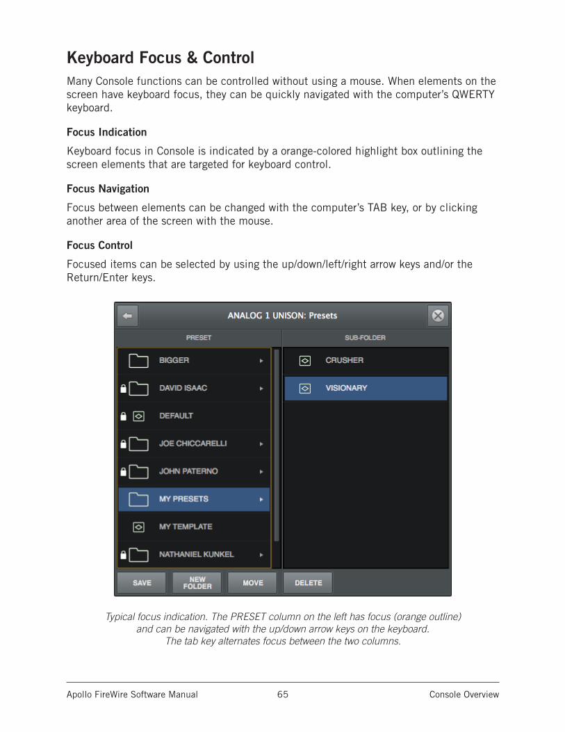
Apollo FireWire Software Manual Console Overview 65
Keyboard Focus & ControlMany Console functions can be controlled without using a mouse. When elements on the screen have keyboard focus, they can be quickly navigated with the computer’s QWERTY keyboard.
Focus Indication
Keyboard focus in Console is indicated by a orange-colored highlight box outlining the screen elements that are targeted for keyboard control.
Focus Navigation
Focus between elements can be changed with the computer’s TAB key, or by clicking another area of the screen with the mouse.
Focus Control
Focused items can be selected by using the up/down/left/right arrow keys and/or the Return/Enter keys.
Typical focus indication. The PRESET column on the left has focus (orange outline) and can be navigated with the up/down arrow keys on the keyboard.
The tab key alternates focus between the two columns.
Apollo FireWire Software Manual Console Overview 66
Adjusting Console ControlsConsole uses typical software control techniques to adjust parameters.
2-state switches: Click to toggle the state.
Knobs: Click+drag to adjust, or use the Controls Shortcuts. Console’s rotary controls (and UAD plug-in knobs) can respond to Linear, Circular, or Relative Circular adjustments modes. The CONTROL MODES preference is set in PLUG-INS panel within the Console Settings window.
Faders: Click+drag to adjust, or use the Controls Shortcuts.
Drop Menus: Click to view the drop menu contents, then click an item in the drop menu to select the item.
UAD Powered Plug-Ins: Most UAD plug-in controls use the same methods as above. However, some plug-in parameters may have custom controls that are unfamiliar or not obvious. All custom controls are detailed for individual plug-ins in the UAD Plug-Ins Manual.
Controls ShortcutsIn addition to the keyboard shortcuts below, several other shortcuts are available to simplify Console control adjustments:
Fine Control: Continuous controls (knobs and faders) can be adjusted with increased resolution by depressing the SHIFT while adjusting these controls.
Scroll Wheel: Continuous controls (knobs and faders) can be adjusted by using the computer input device’s scroll function (e.g., mouse scroll wheel). Hover the cursor over the control and adjust the scroll wheel to modify the parameter value.
Adjust All: If the Option key is held down while modifying any control, the same control on all inputs (or aux returns) will be simultaneously adjusted. The relative difference is maintained between the same controls until any control reaches its minimum or maximum value.
Return To Default: If the Command (Mac) or Ctrl (Windows) key is held when a control is clicked, the control will return to its default value. Command+Option+Click (Mac) or Ctrl+Option+Click (Mac) will return all controls of the same type to their default value.
Mute/Solo All Toggle: Option-click a Mute or Solo switch to toggle the state on all channels.
Drop Menus: Menus continue to display after a single click. The mouse button does not need to be held down to view the menu.
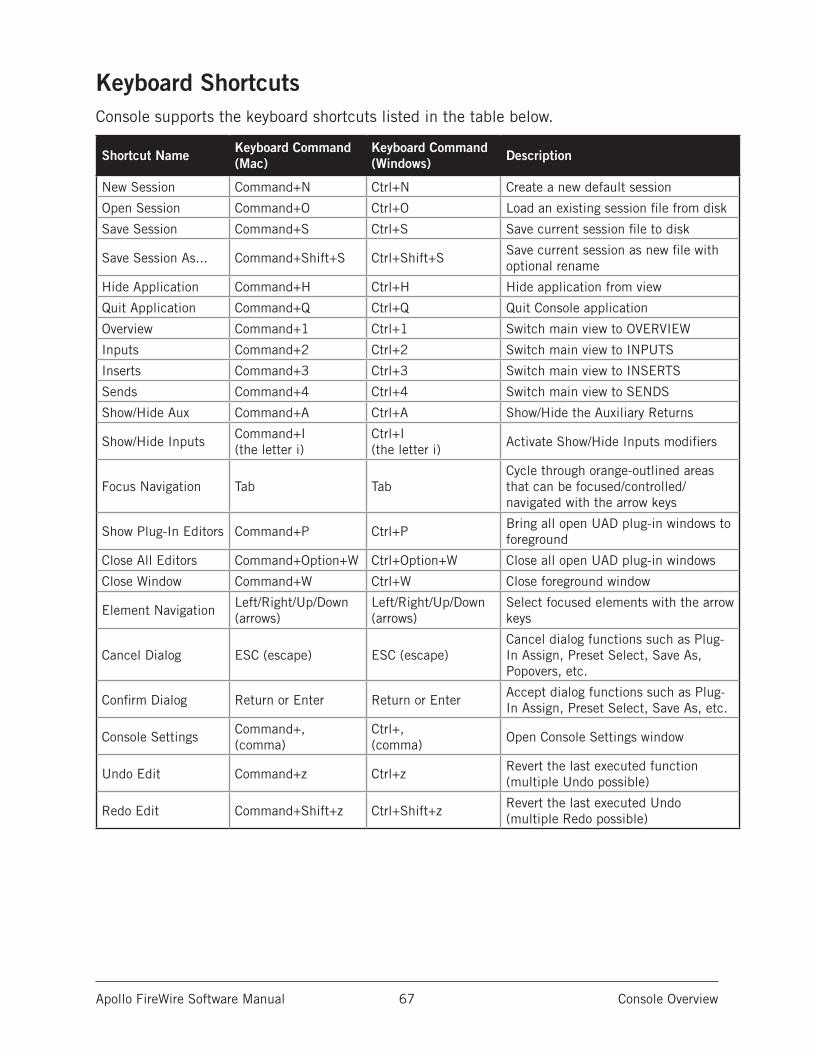
Apollo FireWire Software Manual Console Overview 67
Keyboard ShortcutsConsole supports the keyboard shortcuts listed in the table below.
Shortcut Name Keyboard Command (Mac)
Keyboard Command (Windows) Description
New Session Command+N Ctrl+N Create a new default session
Open Session Command+O Ctrl+O Load an existing session file from disk
Save Session Command+S Ctrl+S Save current session file to disk
Save Session As... Command+Shift+S Ctrl+Shift+SSave current session as new file with optional rename
Hide Application Command+H Ctrl+H Hide application from view
Quit Application Command+Q Ctrl+Q Quit Console application
Overview Command+1 Ctrl+1 Switch main view to OVERVIEW
Inputs Command+2 Ctrl+2 Switch main view to INPUTS
Inserts Command+3 Ctrl+3 Switch main view to INSERTS
Sends Command+4 Ctrl+4 Switch main view to SENDS
Show/Hide Aux Command+A Ctrl+A Show/Hide the Auxiliary Returns
Show/Hide InputsCommand+I (the letter i)
Ctrl+I (the letter i)
Activate Show/Hide Inputs modifiers
Focus Navigation Tab TabCycle through orange-outlined areas that can be focused/controlled/navigated with the arrow keys
Show Plug-In Editors Command+P Ctrl+PBring all open UAD plug-in windows to foreground
Close All Editors Command+Option+W Ctrl+Option+W Close all open UAD plug-in windows
Close Window Command+W Ctrl+W Close foreground window
Element NavigationLeft/Right/Up/Down (arrows)
Left/Right/Up/Down (arrows)
Select focused elements with the arrow keys
Cancel Dialog ESC (escape) ESC (escape)Cancel dialog functions such as Plug-In Assign, Preset Select, Save As, Popovers, etc.
Confirm Dialog Return or Enter Return or EnterAccept dialog functions such as Plug-In Assign, Preset Select, Save As, etc.
Console SettingsCommand+, (comma)
Ctrl+, (comma)
Open Console Settings window
Undo Edit Command+z Ctrl+zRevert the last executed function (multiple Undo possible)
Redo Edit Command+Shift+z Ctrl+Shift+zRevert the last executed Undo (multiple Redo possible)
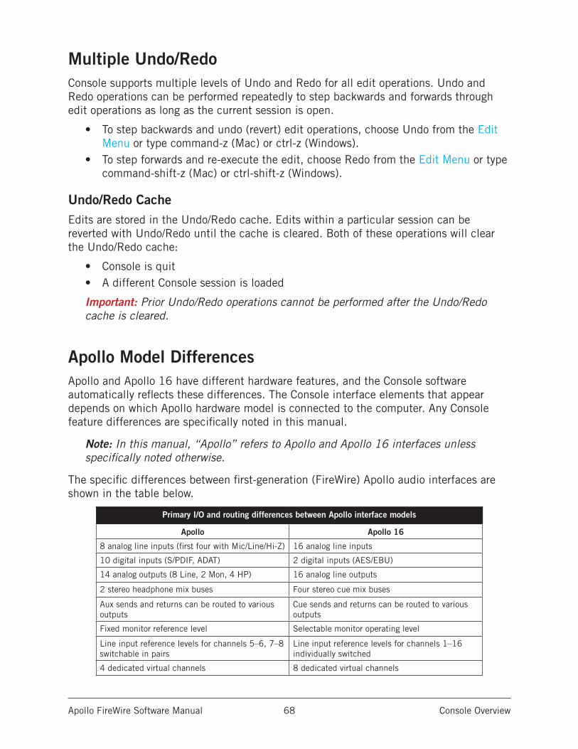
Apollo FireWire Software Manual Console Overview 68
Multiple Undo/RedoConsole supports multiple levels of Undo and Redo for all edit operations. Undo and Redo operations can be performed repeatedly to step backwards and forwards through edit operations as long as the current session is open.
• To step backwards and undo (revert) edit operations, choose Undo from the Edit Menu or type command-z (Mac) or ctrl-z (Windows).
• To step forwards and re-execute the edit, choose Redo from the Edit Menu or type command-shift-z (Mac) or ctrl-shift-z (Windows).
Undo/Redo CacheEdits are stored in the Undo/Redo cache. Edits within a particular session can be reverted with Undo/Redo until the cache is cleared. Both of these operations will clear the Undo/Redo cache:
• Console is quit• A different Console session is loaded
Important: Prior Undo/Redo operations cannot be performed after the Undo/Redo cache is cleared.
Apollo Model DifferencesApollo and Apollo 16 have different hardware features, and the Console software automatically reflects these differences. The Console interface elements that appear depends on which Apollo hardware model is connected to the computer. Any Console feature differences are specifically noted in this manual.
Note: In this manual, “Apollo” refers to Apollo and Apollo 16 interfaces unless specifically noted otherwise.
The specific differences between first-generation (FireWire) Apollo audio interfaces are shown in the table below.
Primary I/O and routing differences between Apollo interface models
Apollo Apollo 16
8 analog line inputs (first four with Mic/Line/Hi-Z) 16 analog line inputs
10 digital inputs (S/PDIF, ADAT) 2 digital inputs (AES/EBU)
14 analog outputs (8 Line, 2 Mon, 4 HP) 16 analog line outputs
2 stereo headphone mix buses Four stereo cue mix buses
Aux sends and returns can be routed to various outputs
Cue sends and returns can be routed to various outputs
Fixed monitor reference level Selectable monitor operating level
Line input reference levels for channels 5–6, 7–8 switchable in pairs
Line input reference levels for channels 1–16 individually switched
4 dedicated virtual channels 8 dedicated virtual channels
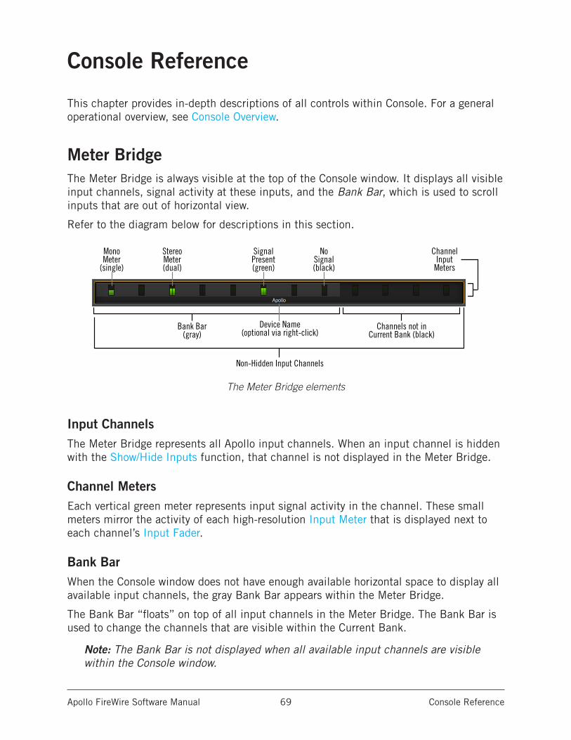
Apollo FireWire Software Manual Console Reference 69
Console Reference
This chapter provides in-depth descriptions of all controls within Console. For a general operational overview, see Console Overview.
Meter BridgeThe Meter Bridge is always visible at the top of the Console window. It displays all visible input channels, signal activity at these inputs, and the Bank Bar, which is used to scroll inputs that are out of horizontal view.
Refer to the diagram below for descriptions in this section.
The Meter Bridge elements
Input ChannelsThe Meter Bridge represents all Apollo input channels. When an input channel is hidden with the Show/Hide Inputs function, that channel is not displayed in the Meter Bridge.
Channel MetersEach vertical green meter represents input signal activity in the channel. These small meters mirror the activity of each high-resolution Input Meter that is displayed next to each channel’s Input Fader.
Bank BarWhen the Console window does not have enough available horizontal space to display all available input channels, the gray Bank Bar appears within the Meter Bridge.
The Bank Bar “floats” on top of all input channels in the Meter Bridge. The Bank Bar is used to change the channels that are visible within the Current Bank.
Note: The Bank Bar is not displayed when all available input channels are visible within the Console window.
StereoMeter(dual)
SignalPresent(green)
NoSignal(black)
MonoMeter
(single)
Channel Input
Meters
Bank Bar(gray)
Channels not inCurrent Bank (black)
Device Name(optional via right-click)
Non-Hidden Input Channels
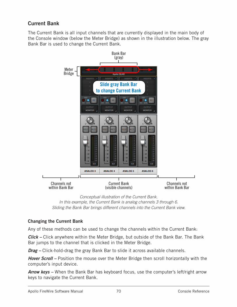
Apollo FireWire Software Manual Console Reference 70
Current Bank
The Current Bank is all input channels that are currently displayed in the main body of the Console window (below the Meter Bridge) as shown in the illustration below. The gray Bank Bar is used to change the Current Bank.
Conceptual illustration of the Current Bank. In this example, the Current Bank is analog channels 3 through 6.
Sliding the Bank Bar brings different channels into the Current Bank view.
Changing the Current Bank
Any of these methods can be used to change the channels within the Current Bank:
Click – Click anywhere within the Meter Bridge, but outside of the Bank Bar. The Bank Bar jumps to the channel that is clicked in the Meter Bridge.
Drag – Click-hold-drag the gray Bank Bar to slide it across available channels.
Hover Scroll – Position the mouse over the Meter Bridge then scroll horizontally with the computer’s input device.
Arrow keys – When the Bank Bar has keyboard focus, use the computer’s left/right arrow keys to navigate the Current Bank.
Slide gray Bank Barto change Current Bank
Bank Bar(gray)
Current Bank(visible channels)
Channels notwithin Bank Bar
Channels notwithin Bank Bar
MeterBridge
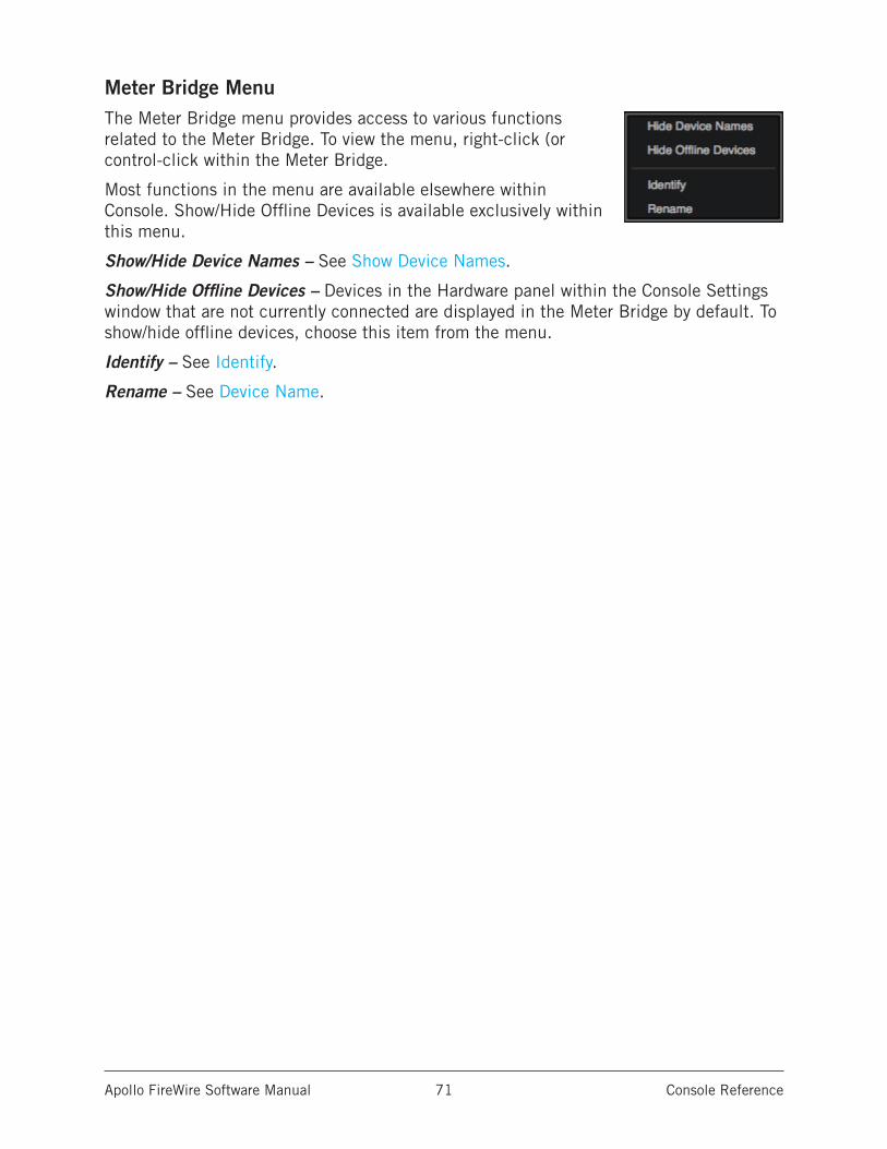
Apollo FireWire Software Manual Console Reference 71
Meter Bridge MenuThe Meter Bridge menu provides access to various functions related to the Meter Bridge. To view the menu, right-click (or control-click within the Meter Bridge.
Most functions in the menu are available elsewhere within Console. Show/Hide Offline Devices is available exclusively within this menu.
Show/Hide Device Names – See Show Device Names.
Show/Hide Offline Devices – Devices in the Hardware panel within the Console Settings window that are not currently connected are displayed in the Meter Bridge by default. To show/hide offline devices, choose this item from the menu.
Identify – See Identify.
Rename – See Device Name.
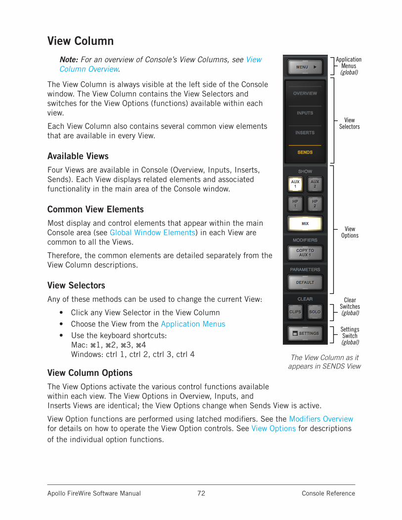
Apollo FireWire Software Manual Console Reference 72
View ColumnNote: For an overview of Console’s View Columns, see View Column Overview.
The View Column is always visible at the left side of the Console window. The View Column contains the View Selectors and switches for the View Options (functions) available within each view.
Each View Column also contains several common view elements that are available in every View.
Available ViewsFour Views are available in Console (Overview, Inputs, Inserts, Sends). Each View displays related elements and associated functionality in the main area of the Console window.
Common View ElementsMost display and control elements that appear within the main Console area (see Global Window Elements) in each View are common to all the Views.
Therefore, the common elements are detailed separately from the View Column descriptions.
View SelectorsAny of these methods can be used to change the current View:
• Click any View Selector in the View Column• Choose the View from the Application Menus• Use the keyboard shortcuts:
Mac: ⌘1, ⌘2, ⌘3, ⌘4 Windows: ctrl 1, ctrl 2, ctrl 3, ctrl 4
View Column OptionsThe View Options activate the various control functions available within each view. The View Options in Overview, Inputs, and Inserts Views are identical; the View Options change when Sends View is active.
View Option functions are performed using latched modifiers. See the Modifiers Overview for details on how to operate the View Option controls. See View Options for descriptions of the individual option functions.
ViewSelectors
ApplicationMenus
(global)
ViewOptions
ClearSwitches(global)
Settings Switch(global)
The View Column as it appears in SENDS View
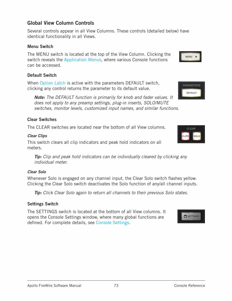
Apollo FireWire Software Manual Console Reference 73
Global View Column ControlsSeveral controls appear in all View Columns. These controls (detailed below) have identical functionality in all Views.
Menu Switch
The MENU switch is located at the top of the View Column. Clicking the switch reveals the Application Menus, where various Console functions can be accessed.
Default Switch
When Option Latch is active with the parameters DEFAULT switch, clicking any control returns the parameter to its default value.
Note: The DEFAULT function is primarily for knob and fader values. It does not apply to any preamp settings, plug-in inserts, SOLO/MUTE switches, monitor levels, customized input names, and similar functions.
Clear Switches
The CLEAR switches are located near the bottom of all View columns.
Clear Clips
This switch clears all clip indicators and peak hold indicators on all meters.
Tip: Clip and peak hold indicators can be individually cleared by clicking any individual meter.
Clear Solo
Whenever Solo is engaged on any channel input, the Clear Solo switch flashes yellow. Clicking the Clear Solo switch deactivates the Solo function of any/all channel inputs.
Tip: Click Clear Solo again to return all channels to their previous Solo states.
Settings Switch
The SETTINGS switch is located at the bottom of all View columns. It opens the Console Settings window, where many global functions are defined. For complete details, see Console Settings.
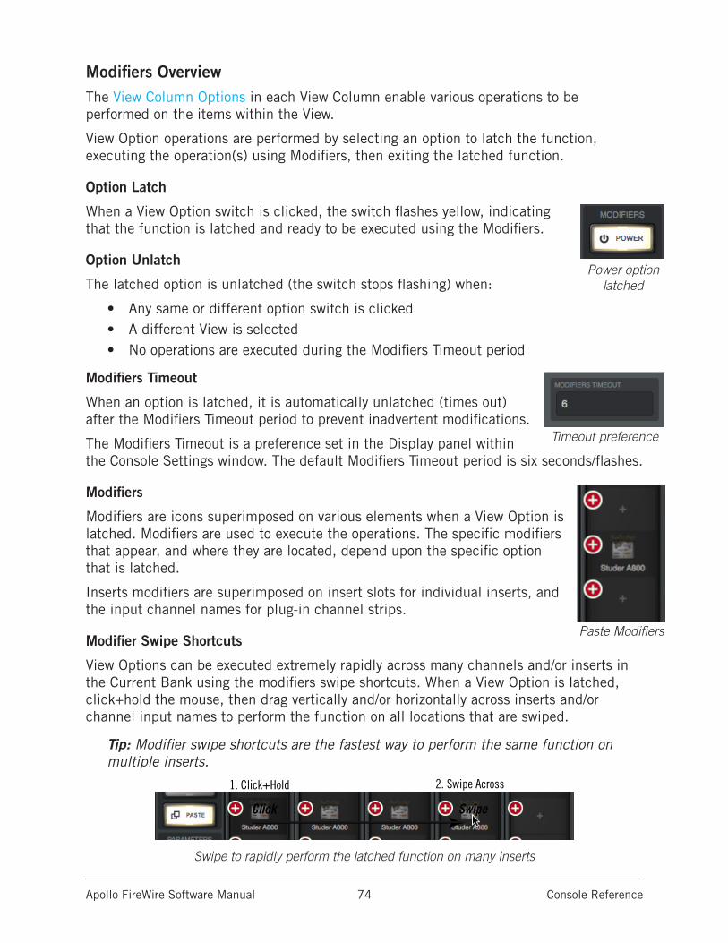
Apollo FireWire Software Manual Console Reference 74
Modifiers OverviewThe View Column Options in each View Column enable various operations to be performed on the items within the View.
View Option operations are performed by selecting an option to latch the function, executing the operation(s) using Modifiers, then exiting the latched function.
Option Latch
When a View Option switch is clicked, the switch flashes yellow, indicating that the function is latched and ready to be executed using the Modifiers.
Option Unlatch
The latched option is unlatched (the switch stops flashing) when:
• Any same or different option switch is clicked• A different View is selected• No operations are executed during the Modifiers Timeout period
Modifiers Timeout
When an option is latched, it is automatically unlatched (times out) after the Modifiers Timeout period to prevent inadvertent modifications.
The Modifiers Timeout is a preference set in the Display panel within the Console Settings window. The default Modifiers Timeout period is six seconds/flashes.
Modifiers
Modifiers are icons superimposed on various elements when a View Option is latched. Modifiers are used to execute the operations. The specific modifiers that appear, and where they are located, depend upon the specific option that is latched.
Inserts modifiers are superimposed on insert slots for individual inserts, and the input channel names for plug-in channel strips.
Modifier Swipe Shortcuts
View Options can be executed extremely rapidly across many channels and/or inserts in the Current Bank using the modifiers swipe shortcuts. When a View Option is latched, click+hold the mouse, then drag vertically and/or horizontally across inserts and/or channel input names to perform the function on all locations that are swiped.
Tip: Modifier swipe shortcuts are the fastest way to perform the same function on multiple inserts.
Swipe to rapidly perform the latched function on many inserts
Power option latched
Timeout preference
Paste Modifiers
1. Click+Hold
Click Swipe
2. Swipe Across
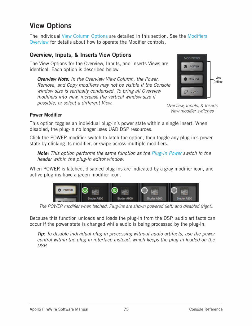
Apollo FireWire Software Manual Console Reference 75
View OptionsThe individual View Column Options are detailed in this section. See the Modifiers Overview for details about how to operate the Modifier controls.
Overview, Inputs, & Inserts View OptionsThe View Options for the Overview, Inputs, and Inserts Views are identical. Each option is described below.
Overview Note: In the Overview View Column, the Power, Remove, and Copy modifiers may not be visible if the Console window size is vertically condensed. To bring all Overview modifiers into view, increase the vertical window size if possible, or select a different View.
Power Modifier
This option toggles an individual plug-in’s power state within a single insert. When disabled, the plug-in no longer uses UAD DSP resources.
Click the POWER modifier switch to latch the option, then toggle any plug-in’s power state by clicking its modifier, or swipe across multiple modifiers.
Note: This option performs the same function as the Plug-In Power switch in the header within the plug-in editor window.
When POWER is latched, disabled plug-ins are indicated by a gray modifier icon, and active plug-ins have a green modifier icon.
The POWER modifier when latched. Plug-ins are shown powered (left) and disabled (right).
Because this function unloads and loads the plug-in from the DSP, audio artifacts can occur if the power state is changed while audio is being processed by the plug-in.
Tip: To disable individual plug-in processing without audio artifacts, use the power control within the plug-in interface instead, which keeps the plug-in loaded on the DSP.
ViewOptions
Sends ViewOptions
(Apollo 16)
Sends ViewOptions(Apollo)
Overview, Inputs, & Inserts View modifier switches
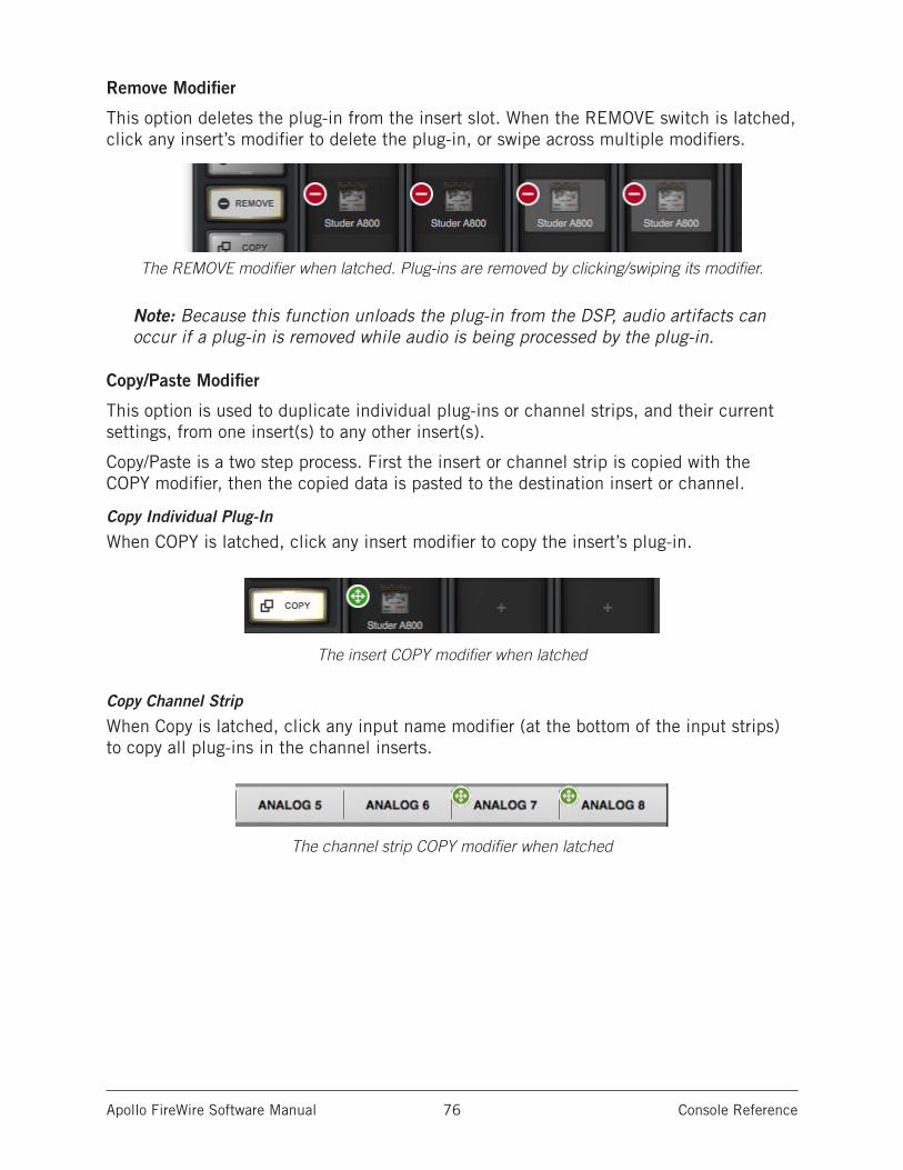
Apollo FireWire Software Manual Console Reference 76
Remove Modifier
This option deletes the plug-in from the insert slot. When the REMOVE switch is latched, click any insert’s modifier to delete the plug-in, or swipe across multiple modifiers.
The REMOVE modifier when latched. Plug-ins are removed by clicking/swiping its modifier.
Note: Because this function unloads the plug-in from the DSP, audio artifacts can occur if a plug-in is removed while audio is being processed by the plug-in.
Copy/Paste Modifier
This option is used to duplicate individual plug-ins or channel strips, and their current settings, from one insert(s) to any other insert(s).
Copy/Paste is a two step process. First the insert or channel strip is copied with the COPY modifier, then the copied data is pasted to the destination insert or channel.
Copy Individual Plug-In
When COPY is latched, click any insert modifier to copy the insert’s plug-in.
The insert COPY modifier when latched
Copy Channel Strip
When Copy is latched, click any input name modifier (at the bottom of the input strips) to copy all plug-ins in the channel inserts.
The channel strip COPY modifier when latched
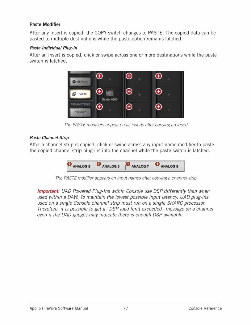
Apollo FireWire Software Manual Console Reference 77
Paste Modifier
After any insert is copied, the COPY switch changes to PASTE. The copied data can be pasted to multiple destinations while the paste option remains latched.
Paste Individual Plug-In
After an insert is copied, click or swipe across one or more destinations while the paste switch is latched.
The PASTE modifiers appear on all inserts after copying an insert
Paste Channel Strip
After a channel strip is copied, click or swipe across any input name modifier to paste the copied channel strip plug-ins into the channel while the paste switch is latched.
The PASTE modifier appears on input names after copying a channel strip
Important: UAD Powered Plug-Ins within Console use DSP differently than when used within a DAW. To maintain the lowest possible input latency, UAD plug-ins used on a single Console channel strip must run on a single SHARC processor. Therefore, it is possible to get a “DSP load limit exceeded” message on a channel even if the UAD gauges may indicate there is enough DSP available.
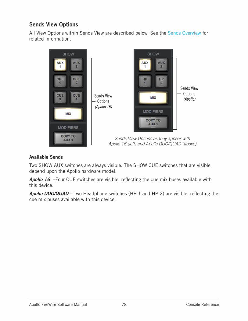
Apollo FireWire Software Manual Console Reference 78
Sends View OptionsAll View Options within Sends View are described below. See the Sends Overview for related information.
Available Sends
Two SHOW AUX switches are always visible. The SHOW CUE switches that are visible depend upon the Apollo hardware model:
Apollo 16 –Four CUE switches are visible, reflecting the cue mix buses available with this device.
Apollo DUO/QUAD – Two Headphone switches (HP 1 and HP 2) are visible, reflecting the cue mix buses available with this device.
ViewOptions
Sends ViewOptions
(Apollo 16)
Sends ViewOptions(Apollo)
Sends View Options as they appear with Apollo 16 (left) and Apollo DUO/QUAD (above)
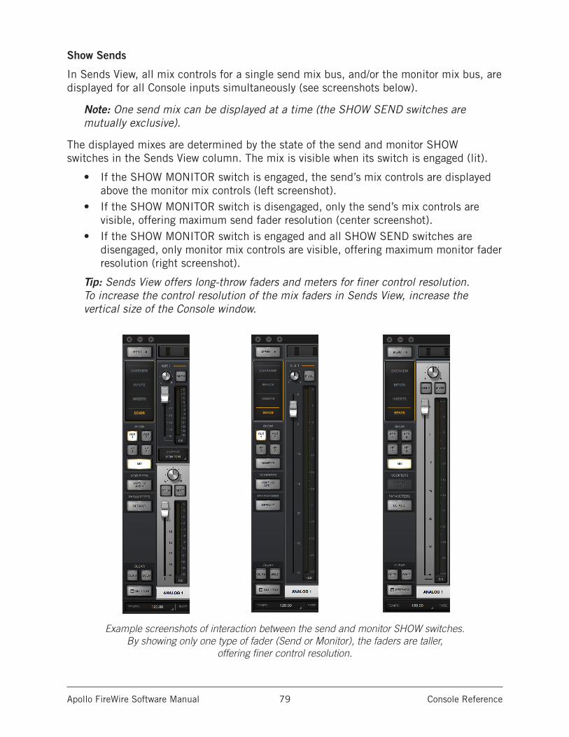
Apollo FireWire Software Manual Console Reference 79
Show Sends
In Sends View, all mix controls for a single send mix bus, and/or the monitor mix bus, are displayed for all Console inputs simultaneously (see screenshots below).
Note: One send mix can be displayed at a time (the SHOW SEND switches are mutually exclusive).
The displayed mixes are determined by the state of the send and monitor SHOW switches in the Sends View column. The mix is visible when its switch is engaged (lit).
• If the SHOW MONITOR switch is engaged, the send’s mix controls are displayed above the monitor mix controls (left screenshot).
• If the SHOW MONITOR switch is disengaged, only the send’s mix controls are visible, offering maximum send fader resolution (center screenshot).
• If the SHOW MONITOR switch is engaged and all SHOW SEND switches are disengaged, only monitor mix controls are visible, offering maximum monitor fader resolution (right screenshot).
Tip: Sends View offers long-throw faders and meters for finer control resolution. To increase the control resolution of the mix faders in Sends View, increase the vertical size of the Console window.
Example screenshots of interaction between the send and monitor SHOW switches. By showing only one type of fader (Send or Monitor), the faders are taller,
offering finer control resolution.
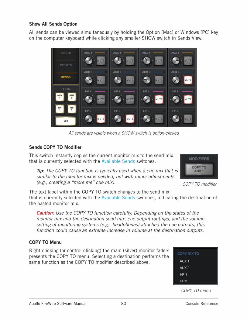
Apollo FireWire Software Manual Console Reference 80
Show All Sends Option
All sends can be viewed simultaneously by holding the Option (Mac) or Windows (PC) key on the computer keyboard while clicking any smaller SHOW switch in Sends View.
All sends are visible when a SHOW switch is option-clicked
Sends COPY TO Modifier
This switch instantly copies the current monitor mix to the send mix that is currently selected with the Available Sends switches.
Tip: The COPY TO function is typically used when a cue mix that is similar to the monitor mix is needed, but with minor adjustments (e.g., creating a “more me” cue mix).
The text label within the COPY TO switch changes to the send mix that is currently selected with the Available Sends switches, indicating the destination of the pasted monitor mix.
Caution: Use the COPY TO function carefully. Depending on the states of the monitor mix and the destination send mix, cue output routings, and the volume setting of monitoring systems (e.g., headphones) attached the cue outputs, this function could cause an extreme increase in volume at the destination outputs.
COPY TO Menu
Right-clicking (or control-clicking) the main (silver) monitor faders presents the COPY TO menu. Selecting a destination performs the same function as the COPY TO modifier described above.
COPY TO modifier
COPY TO menu
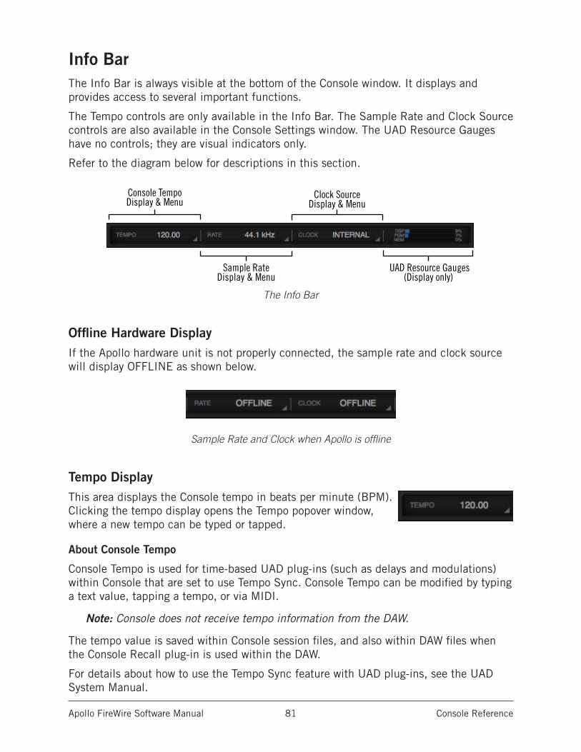
Apollo FireWire Software Manual Console Reference 81
Info BarThe Info Bar is always visible at the bottom of the Console window. It displays and provides access to several important functions.
The Tempo controls are only available in the Info Bar. The Sample Rate and Clock Source controls are also available in the Console Settings window. The UAD Resource Gauges have no controls; they are visual indicators only.
Refer to the diagram below for descriptions in this section.
The Info Bar
Offline Hardware DisplayIf the Apollo hardware unit is not properly connected, the sample rate and clock source will display OFFLINE as shown below.
Sample Rate and Clock when Apollo is offline
Tempo DisplayThis area displays the Console tempo in beats per minute (BPM). Clicking the tempo display opens the Tempo popover window, where a new tempo can be typed or tapped.
About Console Tempo
Console Tempo is used for time-based UAD plug-ins (such as delays and modulations) within Console that are set to use Tempo Sync. Console Tempo can be modified by typing a text value, tapping a tempo, or via MIDI.
Note: Console does not receive tempo information from the DAW.
The tempo value is saved within Console session files, and also within DAW files when the Console Recall plug-in is used within the DAW.
For details about how to use the Tempo Sync feature with UAD plug-ins, see the UAD System Manual.
Console TempoDisplay & Menu
Sample RateDisplay & Menu
Clock SourceDisplay & Menu
UAD Resource Gauges(Display only)
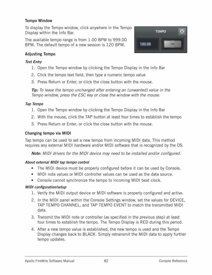
Apollo FireWire Software Manual Console Reference 82
Tempo Window
To display the Tempo window, click anywhere in the Tempo Display within the Info Bar.
The available tempo range is from 1.00 BPM to 999.00 BPM. The default tempo of a new session is 120 BPM.
Adjusting Tempo
Text Entry
1. Open the Tempo window by clicking the Tempo Display in the Info Bar
2. Click the tempo text field, then type a numeric tempo value
3. Press Return or Enter, or click the close button with the mouse.
Tip: To leave the tempo unchanged after entering an (unwanted) value in the Tempo window, press the ESC key or close the window with the mouse.
Tap Tempo
1. Open the Tempo window by clicking the Tempo Display in the Info Bar
2. With the mouse, click the TAP button at least four times to establish the tempo
3. Press Return or Enter, or click the close button with the mouse.
Changing tempo via MIDI
Tap tempo can be used to set a new tempo from incoming MIDI data. This method requires any external MIDI hardware and/or MIDI software that is recognized by the OS.
Note: MIDI drivers for the MIDI device may need to be installed and/or configured.
About external MIDI tap tempo control
• The MIDI device must be properly configured before it can be used by Console.• MIDI note values or MIDI controller values can be used as the data source.• Console cannot synchronize the tempo to incoming MIDI beat clock.
MIDI configuration/setup
1. Verify the MIDI output device or MIDI software is properly configured and active.
2. In the MIDI panel within the Console Settings window, set the values for DEVICE, TAP TEMPO CHANNEL, and TAP TEMPO EVENT to match the transmitted MIDI data.
3. Transmit the MIDI note or controller (as specified in the previous step) at least four times to establish the tempo. The Tempo Display is RED during this period.
4. After a new tempo value is established, the new tempo is used and the Tempo Display changes back to BLACK. Simply retransmit the MIDI data to apply further tempo updates.
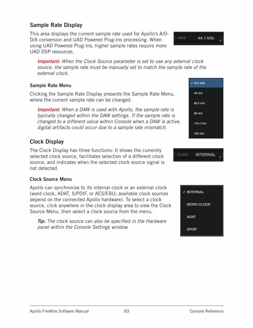
Apollo FireWire Software Manual Console Reference 83
Sample Rate DisplayThis area displays the current sample rate used for Apollo’s A/D-D/A conversion and UAD Powered Plug-Ins processing. When using UAD Powered Plug-Ins, higher sample rates require more UAD DSP resources.
Important: When the Clock Source parameter is set to use any external clock source, the sample rate must be manually set to match the sample rate of the external clock.
Sample Rate Menu
Clicking the Sample Rate Display presents the Sample Rate Menu, where the current sample rate can be changed.
Important: When a DAW is used with Apollo, the sample rate is typically changed within the DAW settings. If the sample rate is changed to a different value within Console when a DAW is active, digital artifacts could occur due to a sample rate mismatch.
Clock DisplayThe Clock Display has three functions: It shows the currently selected clock source, facilitates selection of a different clock source, and indicates when the selected clock source signal is not detected.
Clock Source Menu
Apollo can synchronize to its internal clock or an external clock (word clock, ADAT, S/PDIF, or AES/EBU; available clock sources depend on the connected Apollo hardware). To select a clock source, click anywhere in the clock display area to view the Clock Source Menu, then select a clock source from the menu.
Tip: The clock source can also be specified in the Hardware panel within the Console Settings window.
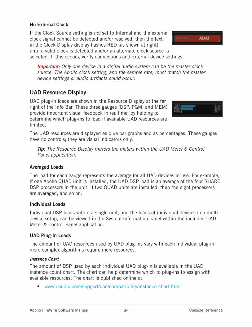
Apollo FireWire Software Manual Console Reference 84
No External Clock
If the Clock Source setting is not set to Internal and the external clock signal cannot be detected and/or resolved, then the text in the Clock Display display flashes RED (as shown at right) until a valid clock is detected and/or an alternate clock source is selected. If this occurs, verify connections and external device settings.
Important: Only one device in a digital audio system can be the master clock source. The Apollo clock setting, and the sample rate, must match the master device settings or audio artifacts could occur.
UAD Resource DisplayUAD plug-in loads are shown in the Resource Display at the far right of the Info Bar. These three gauges (DSP, PGM, and MEM) provide important visual feedback in realtime, by helping to determine which plug-ins to load if available UAD resources are limited.
The UAD resources are displayed as blue bar graphs and as percentages. These gauges have no controls; they are visual indicators only.
Tip: The Resource Display mirrors the meters within the UAD Meter & Control Panel application.
Averaged Loads
The load for each gauge represents the average for all UAD devices in use. For example, if one Apollo QUAD unit is installed, the UAD DSP load is an average of the four SHARC DSP processors in the unit. If two QUAD units are installed, then the eight processors are averaged, and so on.
Individual Loads
Individual DSP loads within a single unit, and the loads of individual devices in a multi-device setup, can be viewed in the System Information panel within the included UAD Meter & Control Panel application.
UAD Plug-In Loads
The amount of UAD resources used by UAD plug-ins vary with each individual plug-in; more complex algorithms require more resources.
Instance Chart
The amount of DSP used by each individual UAD plug-in is available in the UAD instance count chart. The chart can help determine which to plug-ins to assign with available resources. The chart is published online at:
• www.uaudio.com/support/uad/compatibility/instance-chart.html
Apollo FireWire Software Manual Console Reference 85
Static Loads
Apollo uses UAD DSP and memory for its internal DSP mixer, therefore the meters will indicate loads (when the hardware is connected) even if UAD plug-ins are not inserted.
DSP
The DSP gauge indicates the amount of digital signal processing resources that are being used by all UAD devices in the system.
DSP is the primary hardware resource that powers the UAD Powered Plug-Ins algorithms. When UAD plug-ins are disabled, DSP requirements are decreased.
Note: When UAD plug-ins are disabled, DSP requirements are decreased EXCEPT when the plug-in is disabled using the Power control within the plug-in interface.
Program
The Program (PGM) gauge indicates how much UAD program memory (PGM) is in use. Program memory is an on-chip memory that is specific to the UAD-2 DSP processor(s) and is used for certain UAD plug-in resources.
Each unique UAD plug-in uses a bit of program memory. If many different UAD plug-ins are loaded simultaneously, it is possible for this resource to run out before a DSP overload occurs. This point is considered and factored in by the automatic UAD load balancing routines.
Memory
The Memory (MEM) gauge indicates the percentage of UAD RAM that is currently in use. It indicates the total available UAD memory available, regardless of the number of DSP processors that are installed.
Memory is used for echo, delay lines, reverb, and similar spatial processing. When UAD plug-ins are disabled but not unloaded, memory requirements are not decreased. In this case, the memory remains loaded so that reverb tails and delay lines are not cut off when the plug-in is disabled.
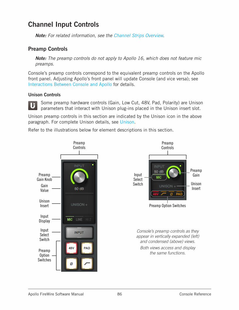
Apollo FireWire Software Manual Console Reference 86
Channel Input ControlsNote: For related information, see the Channel Strips Overview.
Preamp Controls
Note: The preamp controls do not apply to Apollo 16, which does not feature mic preamps.
Console’s preamp controls correspond to the equivalent preamp controls on the Apollo front panel. Adjusting Apollo’s front panel will update Console (and vice versa); see Interactions Between Console and Apollo for details.
Unison Controls
Some preamp hardware controls (Gain, Low Cut, 48V, Pad, Polarity) are Unison parameters that interact with Unison plug-ins placed in the Unison insert slot.
Unison preamp controls in this section are indicated by the Unison icon in the above paragraph. For complete Unison details, see Unison.
Refer to the illustrations below for element descriptions in this section.
PreampGain Knob
UnisonInsert
InputSelectSwitch
InputDisplay
PreampOption
Switches
PreampControls
Gain Value
PreampGain
UnisonInsert
InputSelectSwitch
Preamp Option Switches
PreampControls
PreampGain Knob
UnisonInsert
InputSelectSwitch
InputDisplay
PreampOption
Switches
PreampControls
Gain Value
PreampGain
UnisonInsert
InputSelectSwitch
Preamp Option Switches
PreampControls
Console’s preamp controls as they appear in vertically expanded (left)
and condensed (above) views.
Both views access and display the same functions.
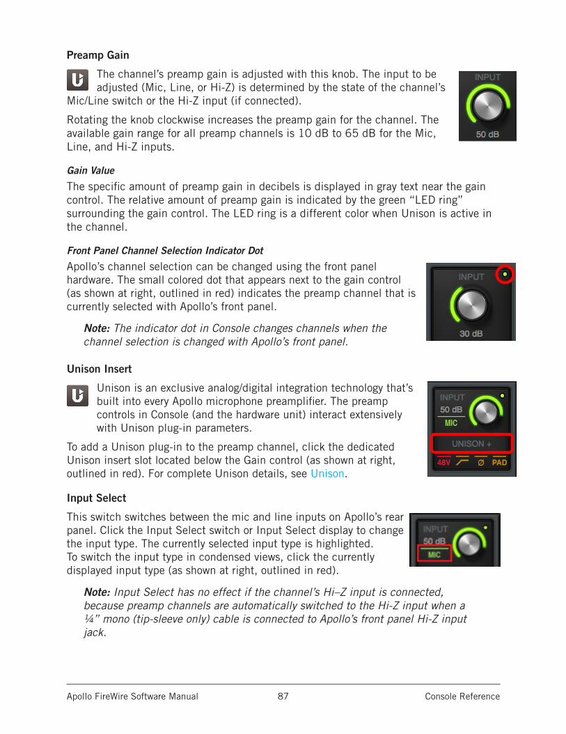
Apollo FireWire Software Manual Console Reference 87
Preamp Gain
The channel’s preamp gain is adjusted with this knob. The input to be adjusted (Mic, Line, or Hi-Z) is determined by the state of the channel’s
Mic/Line switch or the Hi-Z input (if connected).
Rotating the knob clockwise increases the preamp gain for the channel. The available gain range for all preamp channels is 10 dB to 65 dB for the Mic, Line, and Hi-Z inputs.
Gain Value
The specific amount of preamp gain in decibels is displayed in gray text near the gain control. The relative amount of preamp gain is indicated by the green “LED ring” surrounding the gain control. The LED ring is a different color when Unison is active in the channel.
Front Panel Channel Selection Indicator Dot
Apollo’s channel selection can be changed using the front panel hardware. The small colored dot that appears next to the gain control (as shown at right, outlined in red) indicates the preamp channel that is currently selected with Apollo’s front panel.
Note: The indicator dot in Console changes channels when the channel selection is changed with Apollo’s front panel.
Unison Insert
Unison is an exclusive analog/digital integration technology that’s built into every Apollo microphone preamplifier. The preamp controls in Console (and the hardware unit) interact extensively with Unison plug-in parameters.
To add a Unison plug-in to the preamp channel, click the dedicated Unison insert slot located below the Gain control (as shown at right, outlined in red). For complete Unison details, see Unison.
Input Select
This switch switches between the mic and line inputs on Apollo’s rear panel. Click the Input Select switch or Input Select display to change the input type. The currently selected input type is highlighted. To switch the input type in condensed views, click the currently displayed input type (as shown at right, outlined in red).
Note: Input Select has no effect if the channel’s Hi–Z input is connected, because preamp channels are automatically switched to the Hi-Z input when a ¼” mono (tip-sleeve only) cable is connected to Apollo’s front panel Hi-Z input jack.
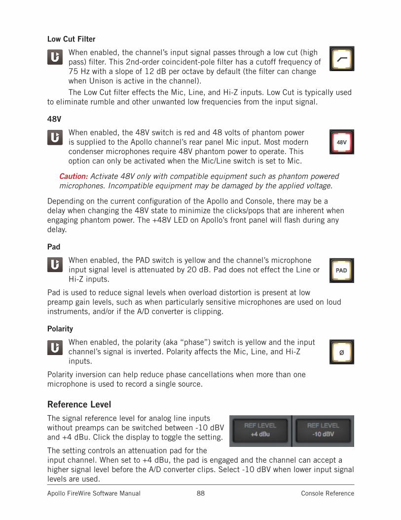
Apollo FireWire Software Manual Console Reference 88
Low Cut Filter
When enabled, the channel’s input signal passes through a low cut (high pass) filter. This 2nd-order coincident-pole filter has a cutoff frequency of 75 Hz with a slope of 12 dB per octave by default (the filter can change when Unison is active in the channel).The Low Cut filter effects the Mic, Line, and Hi-Z inputs. Low Cut is typically used
to eliminate rumble and other unwanted low frequencies from the input signal.
48V
When enabled, the 48V switch is red and 48 volts of phantom power is supplied to the Apollo channel’s rear panel Mic input. Most modern condenser microphones require 48V phantom power to operate. This option can only be activated when the Mic/Line switch is set to Mic.
Caution: Activate 48V only with compatible equipment such as phantom powered microphones. Incompatible equipment may be damaged by the applied voltage.
Depending on the current configuration of the Apollo and Console, there may be a delay when changing the 48V state to minimize the clicks/pops that are inherent when engaging phantom power. The +48V LED on Apollo’s front panel will flash during any delay.
Pad
When enabled, the PAD switch is yellow and the channel’s microphone input signal level is attenuated by 20 dB. Pad does not effect the Line or Hi-Z inputs.
Pad is used to reduce signal levels when overload distortion is present at low preamp gain levels, such as when particularly sensitive microphones are used on loud instruments, and/or if the A/D converter is clipping.
Polarity
When enabled, the polarity (aka “phase”) switch is yellow and the input channel’s signal is inverted. Polarity affects the Mic, Line, and Hi-Z inputs.
Polarity inversion can help reduce phase cancellations when more than one microphone is used to record a single source.
Reference LevelThe signal reference level for analog line inputs without preamps can be switched between -10 dBV and +4 dBu. Click the display to toggle the setting.
The setting controls an attenuation pad for the input channel. When set to +4 dBu, the pad is engaged and the channel can accept a higher signal level before the A/D converter clips. Select -10 dBV when lower input signal levels are used.
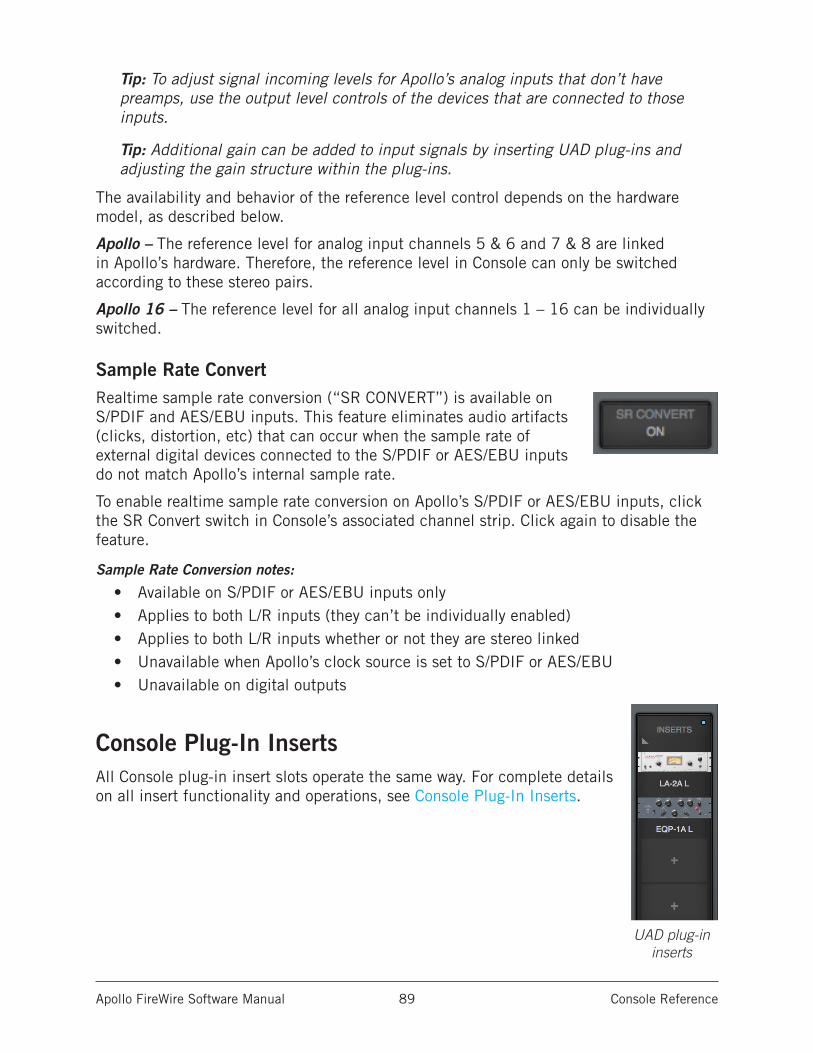
Apollo FireWire Software Manual Console Reference 89
Tip: To adjust signal incoming levels for Apollo’s analog inputs that don’t have preamps, use the output level controls of the devices that are connected to those inputs.
Tip: Additional gain can be added to input signals by inserting UAD plug-ins and adjusting the gain structure within the plug-ins.
The availability and behavior of the reference level control depends on the hardware model, as described below.
Apollo – The reference level for analog input channels 5 & 6 and 7 & 8 are linked in Apollo’s hardware. Therefore, the reference level in Console can only be switched according to these stereo pairs.
Apollo 16 – The reference level for all analog input channels 1 – 16 can be individually switched.
Sample Rate ConvertRealtime sample rate conversion (“SR CONVERT”) is available on S/PDIF and AES/EBU inputs. This feature eliminates audio artifacts (clicks, distortion, etc) that can occur when the sample rate of external digital devices connected to the S/PDIF or AES/EBU inputs do not match Apollo’s internal sample rate.
To enable realtime sample rate conversion on Apollo’s S/PDIF or AES/EBU inputs, click the SR Convert switch in Console’s associated channel strip. Click again to disable the feature.
Sample Rate Conversion notes:
• Available on S/PDIF or AES/EBU inputs only• Applies to both L/R inputs (they can’t be individually enabled)• Applies to both L/R inputs whether or not they are stereo linked• Unavailable when Apollo’s clock source is set to S/PDIF or AES/EBU• Unavailable on digital outputs
Console Plug-In InsertsAll Console plug-in insert slots operate the same way. For complete details on all insert functionality and operations, see Console Plug-In Inserts.
UAD plug-in inserts
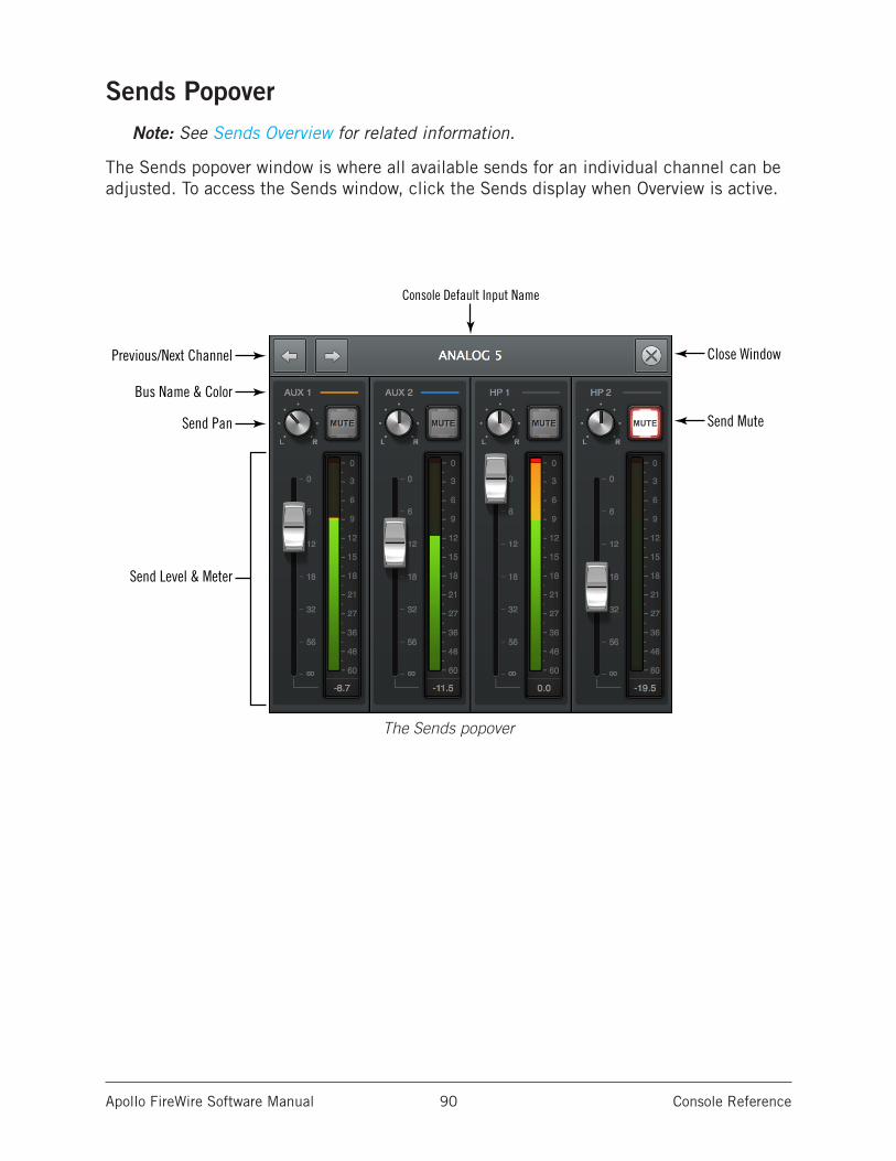
Apollo FireWire Software Manual Console Reference 90
Sends PopoverNote: See Sends Overview for related information.
The Sends popover window is where all available sends for an individual channel can be adjusted. To access the Sends window, click the Sends display when Overview is active.
The Sends popover
Previous/Next Channel
Bus Name & Color
Send Pan
Send Level & Meter
Close Window
Send Mute
Console Default Input Name
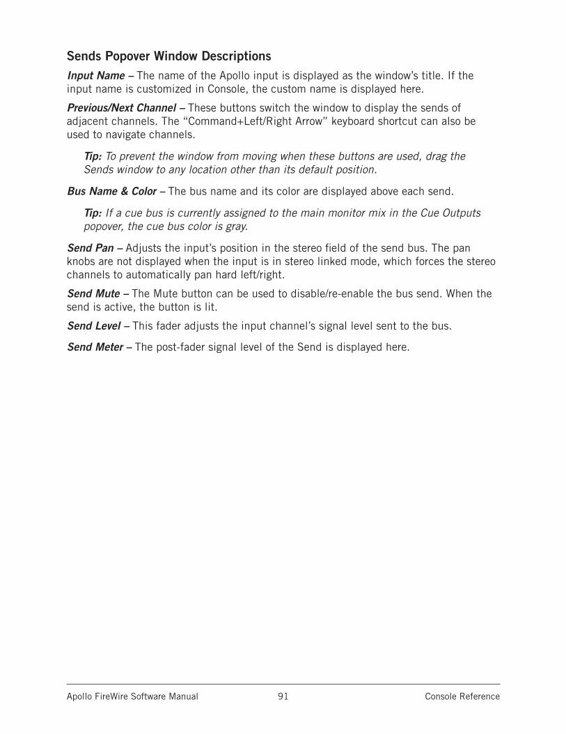
Apollo FireWire Software Manual Console Reference 91
Sends Popover Window DescriptionsInput Name – The name of the Apollo input is displayed as the window’s title. If the input name is customized in Console, the custom name is displayed here.
Previous/Next Channel – These buttons switch the window to display the sends of adjacent channels. The “Command+Left/Right Arrow” keyboard shortcut can also be used to navigate channels.
Tip: To prevent the window from moving when these buttons are used, drag the Sends window to any location other than its default position.
Bus Name & Color – The bus name and its color are displayed above each send.
Tip: If a cue bus is currently assigned to the main monitor mix in the Cue Outputs popover, the cue bus color is gray.
Send Pan – Adjusts the input’s position in the stereo field of the send bus. The pan knobs are not displayed when the input is in stereo linked mode, which forces the stereo channels to automatically pan hard left/right.
Send Mute – The Mute button can be used to disable/re-enable the bus send. When the send is active, the button is lit.
Send Level – This fader adjusts the input channel’s signal level sent to the bus.
Send Meter – The post-fader signal level of the Send is displayed here.
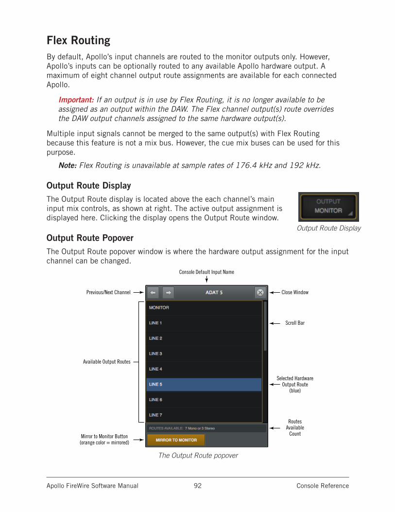
Apollo FireWire Software Manual Console Reference 92
Flex RoutingBy default, Apollo’s input channels are routed to the monitor outputs only. However, Apollo’s inputs can be optionally routed to any available Apollo hardware output. A maximum of eight channel output route assignments are available for each connected Apollo.
Important: If an output is in use by Flex Routing, it is no longer available to be assigned as an output within the DAW. The Flex channel output(s) route overrides the DAW output channels assigned to the same hardware output(s).
Multiple input signals cannot be merged to the same output(s) with Flex Routing because this feature is not a mix bus. However, the cue mix buses can be used for this purpose.
Note: Flex Routing is unavailable at sample rates of 176.4 kHz and 192 kHz.
Output Route DisplayThe Output Route display is located above the each channel’s main input mix controls, as shown at right. The active output assignment is displayed here. Clicking the display opens the Output Route window.
Output Route PopoverThe Output Route popover window is where the hardware output assignment for the input channel can be changed.
The Output Route popover
Output Route Display
Previous/Next Channel
Available Output Routes
Mirror to Monitor Button(orange color = mirrored)
Close Window
Scroll Bar
Selected HardwareOutput Route
(blue)
Routes Available
Count
Console Default Input Name
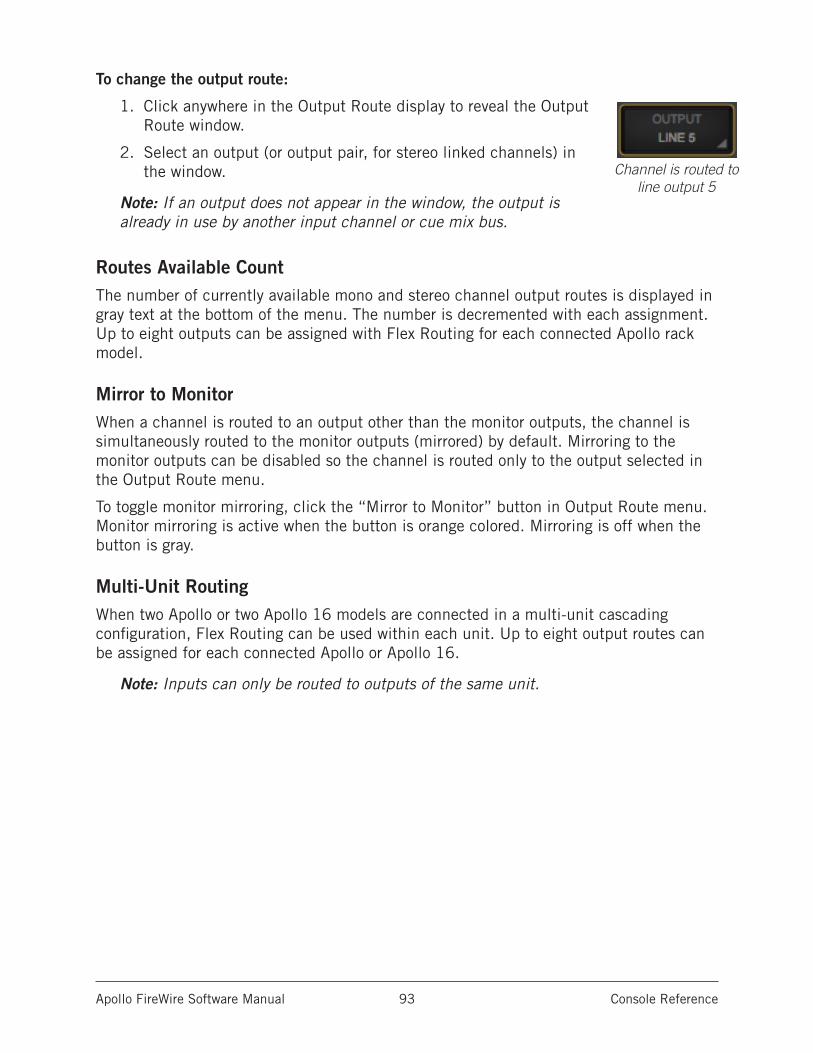
Apollo FireWire Software Manual Console Reference 93
To change the output route:
1. Click anywhere in the Output Route display to reveal the Output Route window.
2. Select an output (or output pair, for stereo linked channels) in the window.
Note: If an output does not appear in the window, the output is already in use by another input channel or cue mix bus.
Routes Available CountThe number of currently available mono and stereo channel output routes is displayed in gray text at the bottom of the menu. The number is decremented with each assignment. Up to eight outputs can be assigned with Flex Routing for each connected Apollo rack model.
Mirror to MonitorWhen a channel is routed to an output other than the monitor outputs, the channel is simultaneously routed to the monitor outputs (mirrored) by default. Mirroring to the monitor outputs can be disabled so the channel is routed only to the output selected in the Output Route menu.
To toggle monitor mirroring, click the “Mirror to Monitor” button in Output Route menu. Monitor mirroring is active when the button is orange colored. Mirroring is off when the button is gray.
Multi-Unit RoutingWhen two Apollo or two Apollo 16 models are connected in a multi-unit cascading configuration, Flex Routing can be used within each unit. Up to eight output routes can be assigned for each connected Apollo or Apollo 16.
Note: Inputs can only be routed to outputs of the same unit.
Channel is routed to line output 5
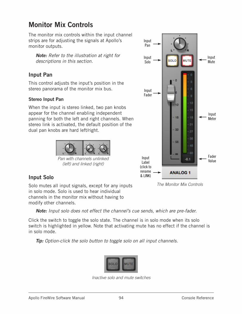
Apollo FireWire Software Manual Console Reference 94
Monitor Mix ControlsThe monitor mix controls within the input channel strips are for adjusting the signals at Apollo’s monitor outputs.
Note: Refer to the illustration at right for descriptions in this section.
Input PanThis control adjusts the input’s position in the stereo panorama of the monitor mix bus.
Stereo Input Pan
When the input is stereo linked, two pan knobs appear for the channel enabling independent panning for both the left and right channels. When stereo link is activated, the default position of the dual pan knobs are hard left/right.
Input SoloSolo mutes all input signals, except for any inputs in solo mode. Solo is used to hear individual channels in the monitor mix without having to modify other channels.
Note: Input solo does not effect the channel’s cue sends, which are pre-fader.
Click the switch to toggle the solo state. The channel is in solo mode when its solo switch is highlighted in yellow. Note that activating mute has no effect if the channel is in solo mode.
Tip: Option-click the solo button to toggle solo on all input channels.
Inactive solo and mute switches
InputLabel
(click to rename& LINK)
InputSolo
InputFader
InputPan
InputMute
InputMeter
Fader Value
The Monitor Mix Controls
Pan with channels unlinked (left) and linked (right)
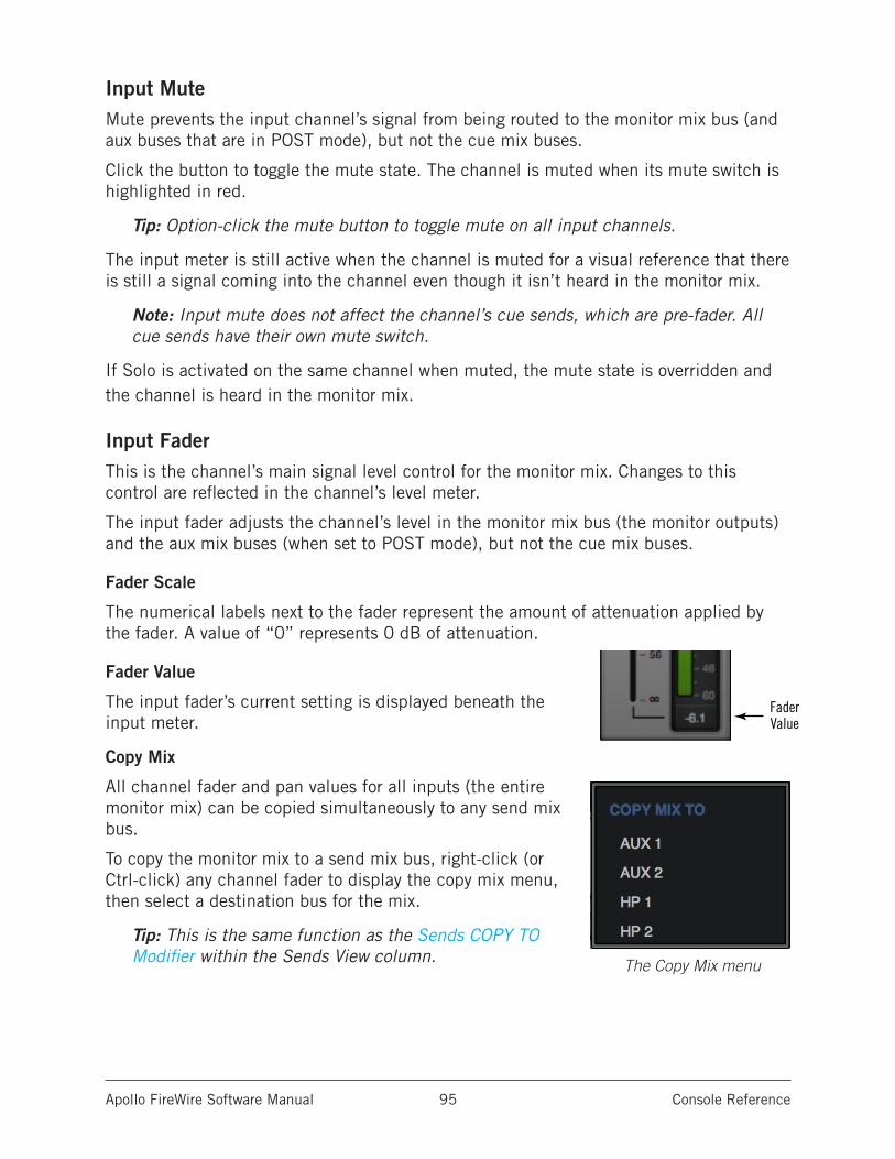
Apollo FireWire Software Manual Console Reference 95
Input MuteMute prevents the input channel’s signal from being routed to the monitor mix bus (and aux buses that are in POST mode), but not the cue mix buses.
Click the button to toggle the mute state. The channel is muted when its mute switch is highlighted in red.
Tip: Option-click the mute button to toggle mute on all input channels.
The input meter is still active when the channel is muted for a visual reference that there is still a signal coming into the channel even though it isn’t heard in the monitor mix.
Note: Input mute does not affect the channel’s cue sends, which are pre-fader. All cue sends have their own mute switch.
If Solo is activated on the same channel when muted, the mute state is overridden and the channel is heard in the monitor mix.
Input FaderThis is the channel’s main signal level control for the monitor mix. Changes to this control are reflected in the channel’s level meter.
The input fader adjusts the channel’s level in the monitor mix bus (the monitor outputs) and the aux mix buses (when set to POST mode), but not the cue mix buses.
Fader Scale
The numerical labels next to the fader represent the amount of attenuation applied by the fader. A value of “0” represents 0 dB of attenuation.
Fader Value
The input fader’s current setting is displayed beneath the input meter.
Copy Mix
All channel fader and pan values for all inputs (the entire monitor mix) can be copied simultaneously to any send mix bus.
To copy the monitor mix to a send mix bus, right-click (or Ctrl-click) any channel fader to display the copy mix menu, then select a destination bus for the mix.
Tip: This is the same function as the Sends COPY TO Modifier within the Sends View column.
InputLabel
(click to rename& LINK)
InputSolo
InputFader
InputPan
InputMute
InputMeter
Fader Value
The Copy Mix menu
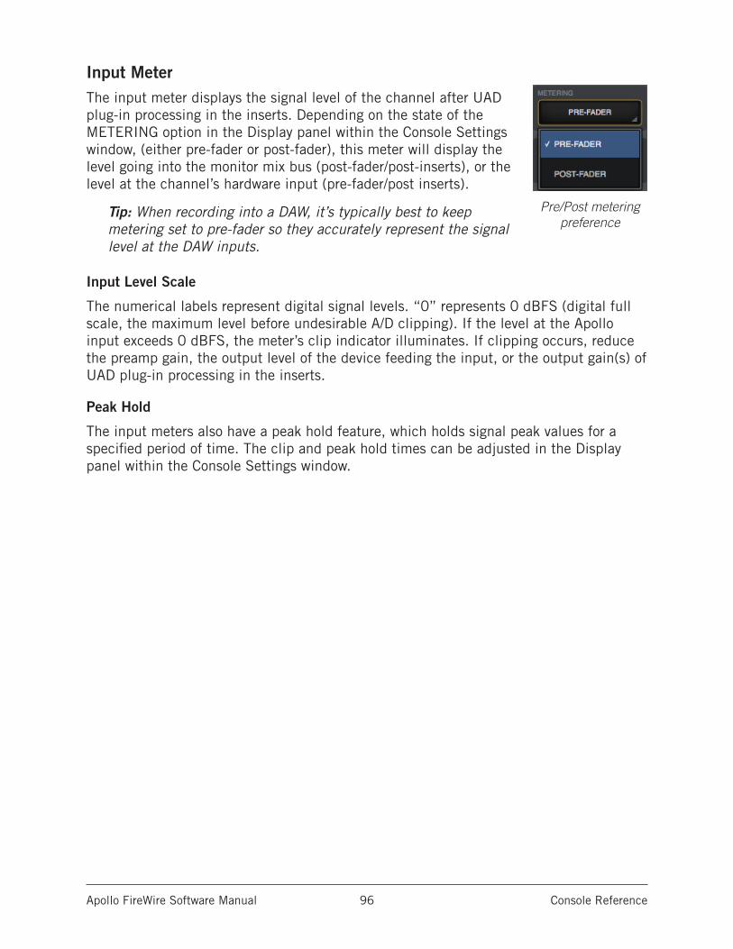
Apollo FireWire Software Manual Console Reference 96
Input MeterThe input meter displays the signal level of the channel after UAD plug-in processing in the inserts. Depending on the state of the METERING option in the Display panel within the Console Settings window, (either pre-fader or post-fader), this meter will display the level going into the monitor mix bus (post-fader/post-inserts), or the level at the channel’s hardware input (pre-fader/post inserts).
Tip: When recording into a DAW, it’s typically best to keep metering set to pre-fader so they accurately represent the signal level at the DAW inputs.
Input Level Scale
The numerical labels represent digital signal levels. “0” represents 0 dBFS (digital full scale, the maximum level before undesirable A/D clipping). If the level at the Apollo input exceeds 0 dBFS, the meter’s clip indicator illuminates. If clipping occurs, reduce the preamp gain, the output level of the device feeding the input, or the output gain(s) of UAD plug-in processing in the inserts.
Peak Hold
The input meters also have a peak hold feature, which holds signal peak values for a specified period of time. The clip and peak hold times can be adjusted in the Display panel within the Console Settings window.
Pre/Post metering preference
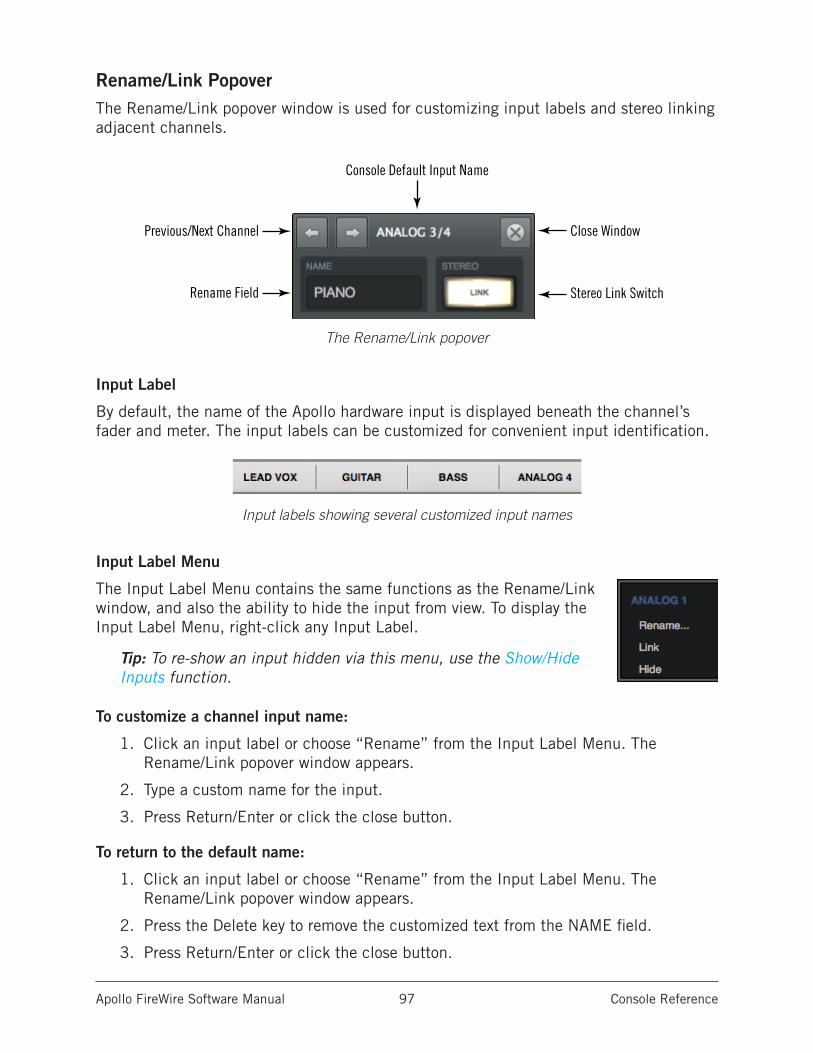
Apollo FireWire Software Manual Console Reference 97
Rename/Link PopoverThe Rename/Link popover window is used for customizing input labels and stereo linking adjacent channels.
The Rename/Link popover
Input Label
By default, the name of the Apollo hardware input is displayed beneath the channel’s fader and meter. The input labels can be customized for convenient input identification.
Input labels showing several customized input names
Input Label Menu
The Input Label Menu contains the same functions as the Rename/Link window, and also the ability to hide the input from view. To display the Input Label Menu, right-click any Input Label.
Tip: To re-show an input hidden via this menu, use the Show/Hide Inputs function.
To customize a channel input name:
1. Click an input label or choose “Rename” from the Input Label Menu. The Rename/Link popover window appears.
2. Type a custom name for the input.
3. Press Return/Enter or click the close button.
To return to the default name:
1. Click an input label or choose “Rename” from the Input Label Menu. The Rename/Link popover window appears.
2. Press the Delete key to remove the customized text from the NAME field.
3. Press Return/Enter or click the close button.
Previous/Next Channel
Rename Field
Close Window
Stereo Link Switch
Console Default Input Name
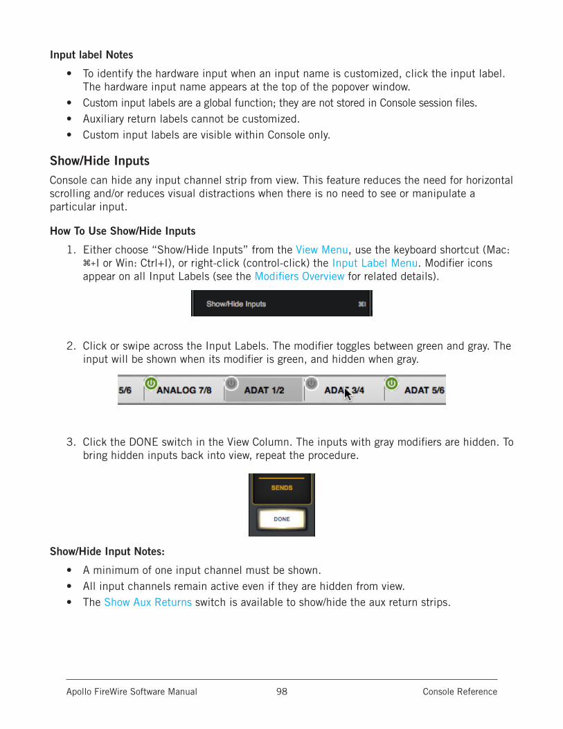
Apollo FireWire Software Manual Console Reference 98
Input label Notes
• To identify the hardware input when an input name is customized, click the input label. The hardware input name appears at the top of the popover window.
• Custom input labels are a global function; they are not stored in Console session files.• Auxiliary return labels cannot be customized.• Custom input labels are visible within Console only.
Show/Hide InputsConsole can hide any input channel strip from view. This feature reduces the need for horizontal scrolling and/or reduces visual distractions when there is no need to see or manipulate a particular input.
How To Use Show/Hide Inputs
1. Either choose “Show/Hide Inputs” from the View Menu, use the keyboard shortcut (Mac: ⌘+I or Win: Ctrl+I), or right-click (control-click) the Input Label Menu. Modifier icons appear on all Input Labels (see the Modifiers Overview for related details).
2. Click or swipe across the Input Labels. The modifier toggles between green and gray. The input will be shown when its modifier is green, and hidden when gray.
3. Click the DONE switch in the View Column. The inputs with gray modifiers are hidden. To bring hidden inputs back into view, repeat the procedure.
Show/Hide Input Notes:
• A minimum of one input channel must be shown.• All input channels remain active even if they are hidden from view.• The Show Aux Returns switch is available to show/hide the aux return strips.
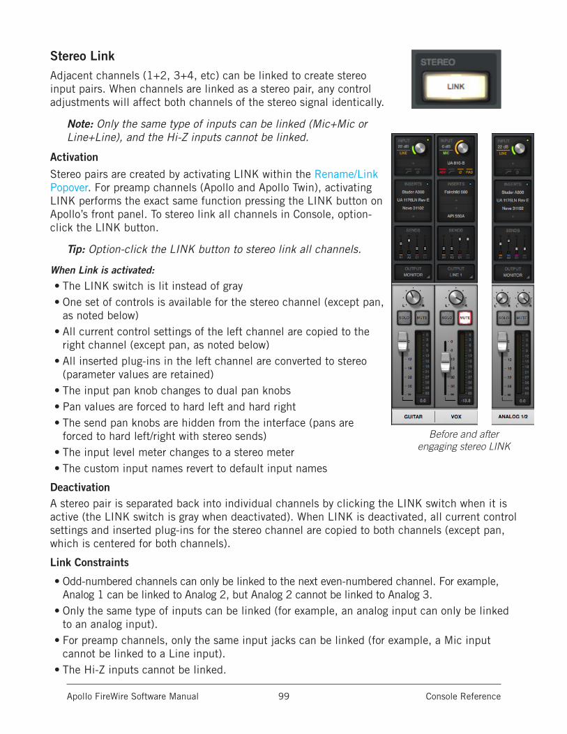
Apollo FireWire Software Manual Console Reference 99
Stereo LinkAdjacent channels (1+2, 3+4, etc) can be linked to create stereo input pairs. When channels are linked as a stereo pair, any control adjustments will affect both channels of the stereo signal identically.
Note: Only the same type of inputs can be linked (Mic+Mic or Line+Line), and the Hi-Z inputs cannot be linked.
Activation
Stereo pairs are created by activating LINK within the Rename/Link Popover. For preamp channels (Apollo and Apollo Twin), activating LINK performs the exact same function pressing the LINK button on Apollo’s front panel. To stereo link all channels in Console, option-click the LINK button.
Tip: Option-click the LINK button to stereo link all channels.
When Link is activated:
• The LINK switch is lit instead of gray• One set of controls is available for the stereo channel (except pan,
as noted below)• All current control settings of the left channel are copied to the
right channel (except pan, as noted below)• All inserted plug-ins in the left channel are converted to stereo
(parameter values are retained) • The input pan knob changes to dual pan knobs• Pan values are forced to hard left and hard right• The send pan knobs are hidden from the interface (pans are
forced to hard left/right with stereo sends)• The input level meter changes to a stereo meter• The custom input names revert to default input names
DeactivationA stereo pair is separated back into individual channels by clicking the LINK switch when it is active (the LINK switch is gray when deactivated). When LINK is deactivated, all current control settings and inserted plug-ins for the stereo channel are copied to both channels (except pan, which is centered for both channels).
Link Constraints
• Odd-numbered channels can only be linked to the next even-numbered channel. For example, Analog 1 can be linked to Analog 2, but Analog 2 cannot be linked to Analog 3.
• Only the same type of inputs can be linked (for example, an analog input can only be linked to an analog input).
• For preamp channels, only the same input jacks can be linked (for example, a Mic input cannot be linked to a Line input).
• The Hi-Z inputs cannot be linked.
Before and after engaging stereo LINK
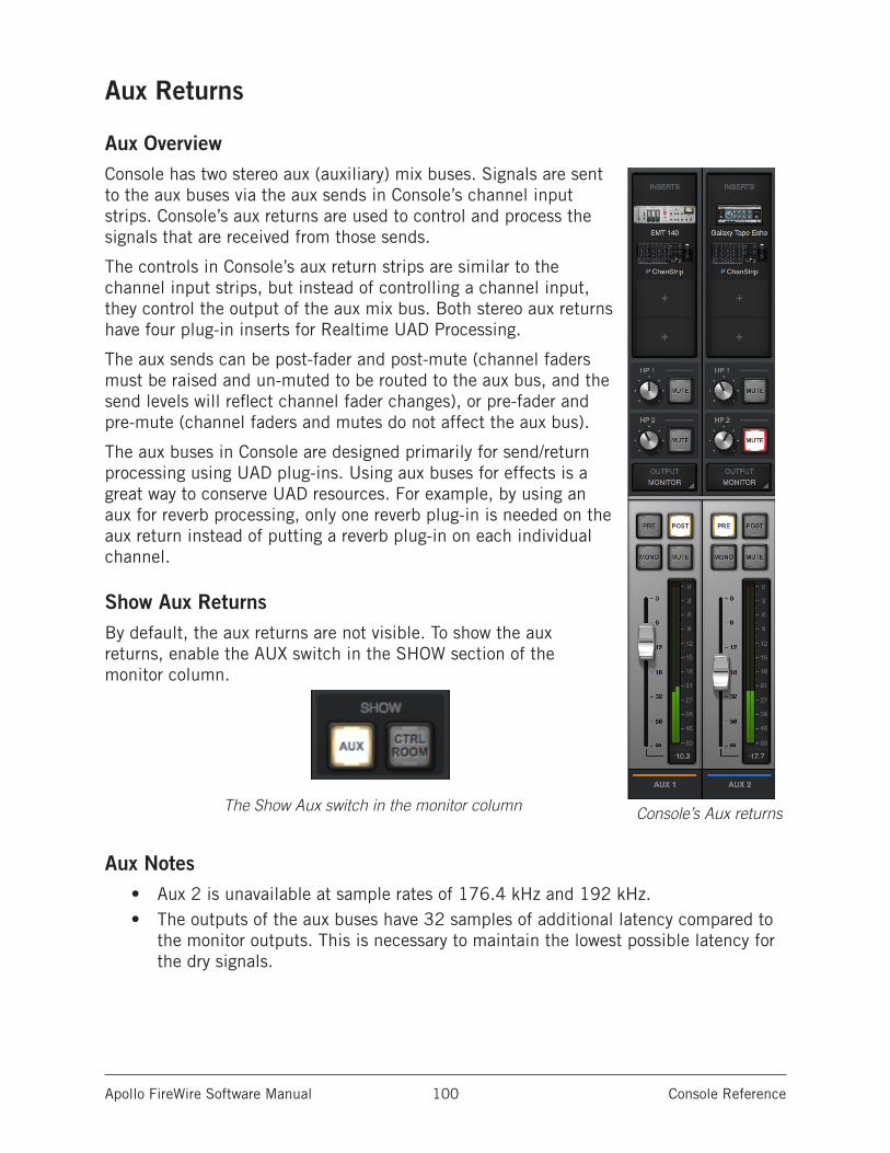
Apollo FireWire Software Manual Console Reference 100
Aux Returns
Aux OverviewConsole has two stereo aux (auxiliary) mix buses. Signals are sent to the aux buses via the aux sends in Console’s channel input strips. Console’s aux returns are used to control and process the signals that are received from those sends.
The controls in Console’s aux return strips are similar to the channel input strips, but instead of controlling a channel input, they control the output of the aux mix bus. Both stereo aux returns have four plug-in inserts for Realtime UAD Processing.
The aux sends can be post-fader and post-mute (channel faders must be raised and un-muted to be routed to the aux bus, and the send levels will reflect channel fader changes), or pre-fader and pre-mute (channel faders and mutes do not affect the aux bus).
The aux buses in Console are designed primarily for send/return processing using UAD plug-ins. Using aux buses for effects is a great way to conserve UAD resources. For example, by using an aux for reverb processing, only one reverb plug-in is needed on the aux return instead of putting a reverb plug-in on each individual channel.
Show Aux ReturnsBy default, the aux returns are not visible. To show the aux returns, enable the AUX switch in the SHOW section of the monitor column.
The Show Aux switch in the monitor column
Aux Notes• Aux 2 is unavailable at sample rates of 176.4 kHz and 192 kHz.• The outputs of the aux buses have 32 samples of additional latency compared to
the monitor outputs. This is necessary to maintain the lowest possible latency for the dry signals.
Console’s Aux returns
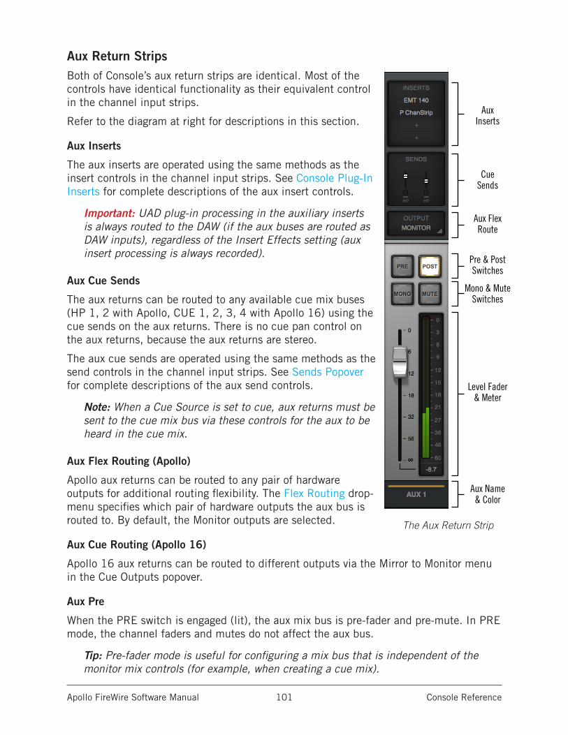
Apollo FireWire Software Manual Console Reference 101
Aux Return StripsBoth of Console’s aux return strips are identical. Most of the controls have identical functionality as their equivalent control in the channel input strips.
Refer to the diagram at right for descriptions in this section.
Aux Inserts
The aux inserts are operated using the same methods as the insert controls in the channel input strips. See Console Plug-In Inserts for complete descriptions of the aux insert controls.
Important: UAD plug-in processing in the auxiliary inserts is always routed to the DAW (if the aux buses are routed as DAW inputs), regardless of the Insert Effects setting (aux insert processing is always recorded).
Aux Cue Sends
The aux returns can be routed to any available cue mix buses (HP 1, 2 with Apollo, CUE 1, 2, 3, 4 with Apollo 16) using the cue sends on the aux returns. There is no cue pan control on the aux returns, because the aux returns are stereo.
The aux cue sends are operated using the same methods as the send controls in the channel input strips. See Sends Popover for complete descriptions of the aux send controls.
Note: When a Cue Source is set to cue, aux returns must be sent to the cue mix bus via these controls for the aux to be heard in the cue mix.
Aux Flex Routing (Apollo)
Apollo aux returns can be routed to any pair of hardware outputs for additional routing flexibility. The Flex Routing drop-menu specifies which pair of hardware outputs the aux bus is routed to. By default, the Monitor outputs are selected.
Aux Cue Routing (Apollo 16)
Apollo 16 aux returns can be routed to different outputs via the Mirror to Monitor menu in the Cue Outputs popover.
Aux Pre
When the PRE switch is engaged (lit), the aux mix bus is pre-fader and pre-mute. In PRE mode, the channel faders and mutes do not affect the aux bus.
Tip: Pre-fader mode is useful for configuring a mix bus that is independent of the monitor mix controls (for example, when creating a cue mix).
AuxInserts
CueSends
Pre & PostSwitches
Level Fader& Meter
Aux Name& Color
Aux Flex Route
Mono & MuteSwitches
The Aux Return Strip
Apollo FireWire Software Manual Console Reference 102
Aux Post
Post-fader is the default setting for Aux 1 and Aux 2. When the POST switch is engaged (lit), the aux mix bus is post-fader and post-mute. In POST mode, the channel faders must be up and un-muted to be routed to the aux bus, and the aux send levels will reflect channel fader changes.
Tip: Post-fader mode is typically used when configuring an effect send mix so the effect sends will interact with the main channel controls.
Aux Mono
This switch sums the left and right channels of the stereo aux mix bus output into a monophonic signal. The aux return output is stereo when the button is gray and mono when the button is lit.
Aux Mute
The aux mute switch stops the aux return’s signal from being routed to the monitor mix. The aux return output is active when the button is gray and muted when the button is lit.
Note: Aux mute does not mute the aux cue sends.
Aux Fader
This is the master signal level control for the aux bus return to the main monitor mix. It does not affect the aux bus return’s cue sends.
Aux Meter
The aux meter displays the signal level of the aux return after UAD plug-in processing in the aux inserts. Depending on the state of the METERING option in the Display panel within the Console Settings window, (either pre-fader or post-fader), this meter will display the aux bus output level routed into the monitor mix bus (post-fader/post-inserts), or the level of the aux mix bus itself (pre-fader/post inserts).
Input Level Scale
The numerical labels represent digital signal levels. “0” represents 0 dBFS (digital full scale, the maximum level before undesirable A/D clipping). If the level of the aux bus exceeds 0 dBFS, the meter’s clip indicator illuminates. If clipping occurs, reduce the aux sends from the input channels and/or the output gain(s) of UAD plug-in processing in the aux inserts.
Peak Hold
The aux meters also have a peak hold feature, which holds signal peak values for a specified period of time. The clip and peak hold times can be adjusted in the Display panel within the Console Settings window.
Tip: When recording into a DAW, it’s typically best to keep metering set to pre-fader so they accurately represent the signal level at the DAW inputs.
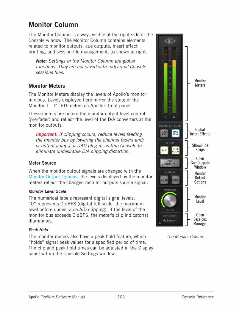
Apollo FireWire Software Manual Console Reference 103
Monitor ColumnThe Monitor Column is always visible at the right side of the Console window. The Monitor Column contains elements related to monitor outputs, cue outputs, insert effect printing, and session file management, as shown at right.
Note: Settings in the Monitor Column are global functions. They are not saved with individual Console sessions files.
Monitor MetersThe Monitor Meters display the levels of Apollo’s monitor mix bus. Levels displayed here mirror the state of the Monitor 1 – 2 LED meters on Apollo’s front panel.
These meters are before the monitor output level control (pre-fader) and reflect the level of the D/A converters at the monitor outputs.
Important: If clipping occurs, reduce levels feeding the monitor bus by lowering the channel faders and/or output gain(s) of UAD plug-ins within Console to eliminate undesirable D/A clipping distortion.
Meter Source
When the monitor output signals are changed with the Monitor Output Options, the levels displayed by the monitor meters reflect the changed monitor outputs source signal.
Monitor Level Scale
The numerical labels represent digital signal levels. “0” represents 0 dBFS (digital full scale, the maximum level before undesirable A/D clipping). If the level of the monitor bus exceeds 0 dBFS, the meter’s clip indicator(s) illuminates.
Peak Hold
The monitor meters also have a peak hold feature, which “holds” signal peak values for a specified period of time. The clip and peak hold times can be adjusted in the Display panel within the Console Settings window.
GlobalInsert Effects
Show/HideStrips
MonitorMeters
OpenCue Outputs
WindowMonitorOutputOptions
MonitorLevel
OpenSessionsManager
The Monitor Column
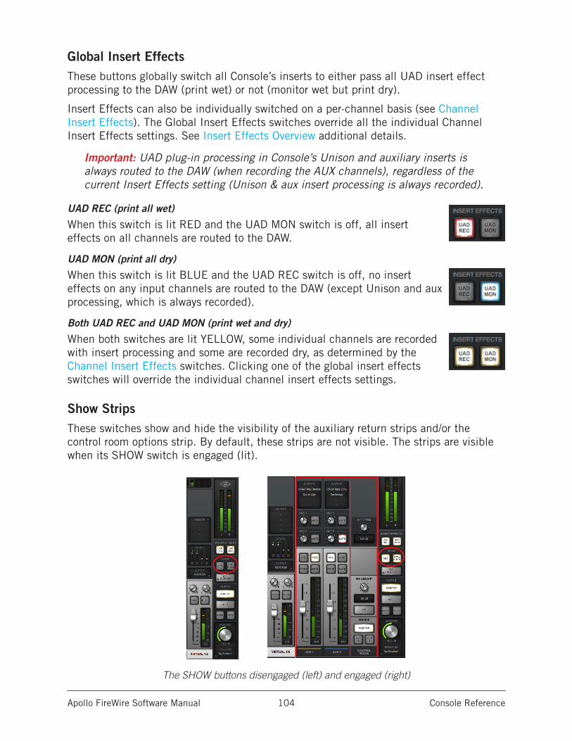
Apollo FireWire Software Manual Console Reference 104
Global Insert EffectsThese buttons globally switch all Console’s inserts to either pass all UAD insert effect processing to the DAW (print wet) or not (monitor wet but print dry).
Insert Effects can also be individually switched on a per-channel basis (see Channel Insert Effects). The Global Insert Effects switches override all the individual Channel Insert Effects settings. See Insert Effects Overview additional details.
Important: UAD plug-in processing in Console’s Unison and auxiliary inserts is always routed to the DAW (when recording the AUX channels), regardless of the current Insert Effects setting (Unison & aux insert processing is always recorded).
UAD REC (print all wet)
When this switch is lit RED and the UAD MON switch is off, all insert effects on all channels are routed to the DAW.
UAD MON (print all dry)
When this switch is lit BLUE and the UAD REC switch is off, no insert effects on any input channels are routed to the DAW (except Unison and aux processing, which is always recorded).
Both UAD REC and UAD MON (print wet and dry)
When both switches are lit YELLOW, some individual channels are recorded with insert processing and some are recorded dry, as determined by the Channel Insert Effects switches. Clicking one of the global insert effects switches will override the individual channel insert effects settings.
Show StripsThese switches show and hide the visibility of the auxiliary return strips and/or the control room options strip. By default, these strips are not visible. The strips are visible when its SHOW switch is engaged (lit).
The SHOW buttons disengaged (left) and engaged (right)
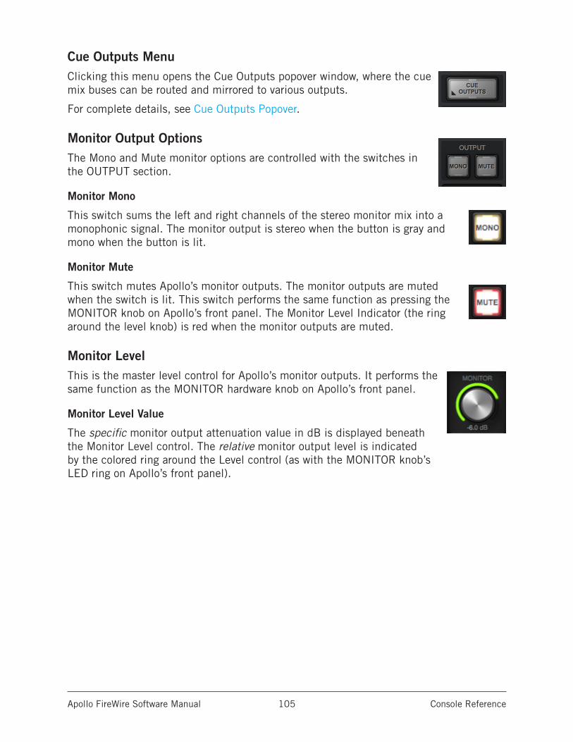
Apollo FireWire Software Manual Console Reference 105
Cue Outputs MenuClicking this menu opens the Cue Outputs popover window, where the cue mix buses can be routed and mirrored to various outputs.
For complete details, see Cue Outputs Popover.
Monitor Output OptionsThe Mono and Mute monitor options are controlled with the switches in the OUTPUT section.
Monitor Mono
This switch sums the left and right channels of the stereo monitor mix into a monophonic signal. The monitor output is stereo when the button is gray and mono when the button is lit.
Monitor Mute
This switch mutes Apollo’s monitor outputs. The monitor outputs are muted when the switch is lit. This switch performs the same function as pressing the MONITOR knob on Apollo’s front panel. The Monitor Level Indicator (the ring around the level knob) is red when the monitor outputs are muted.
Monitor LevelThis is the master level control for Apollo’s monitor outputs. It performs the same function as the MONITOR hardware knob on Apollo’s front panel.
Monitor Level Value
The specific monitor output attenuation value in dB is displayed beneath the Monitor Level control. The relative monitor output level is indicated by the colored ring around the Level control (as with the MONITOR knob’s LED ring on Apollo’s front panel).
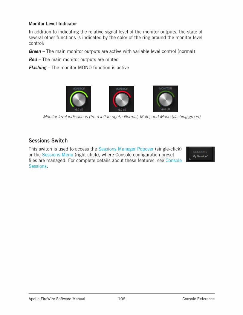
Apollo FireWire Software Manual Console Reference 106
Monitor Level Indicator
In addition to indicating the relative signal level of the monitor outputs, the state of several other functions is indicated by the color of the ring around the monitor level control:
Green – The main monitor outputs are active with variable level control (normal)
Red – The main monitor outputs are muted
Flashing – The monitor MONO function is active
Monitor level indications (from left to right): Normal, Mute, and Mono (flashing green)
Sessions SwitchThis switch is used to access the Sessions Manager Popover (single-click) or the Sessions Menu (right-click), where Console configuration preset files are managed. For complete details about these features, see Console Sessions.
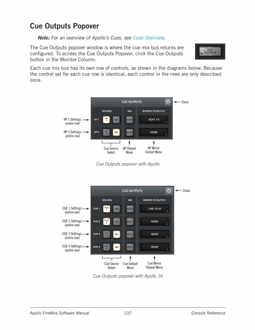
Apollo FireWire Software Manual Console Reference 107
Cue Outputs PopoverNote: For an overview of Apollo’s Cues, see Cues Overview.
The Cue Outputs popover window is where the cue mix bus returns are configured. To access the Cue Outputs Popover, click the Cue Outputs button in the Monitor Column.
Each cue mix bus has its own row of controls, as shown in the diagrams below. Because the control set for each cue row is identical, each control in the rows are only described once.
Cue Outputs popover with Apollo
Cue Outputs popover with Apollo 16
Close
HP OutputMono
Cue Source Select
HP MirrorOutput Menu
HP 1 Settings(entire row)
HP 2 Settings(entire row)
Close
Cue OutputMono
Cue SourceSelect
Cue MirrorOutput Menu
CUE 1 Settings(entire row)
CUE 2 Settings(entire row)
CUE 3 Settings(entire row)
CUE 4 Settings(entire row)
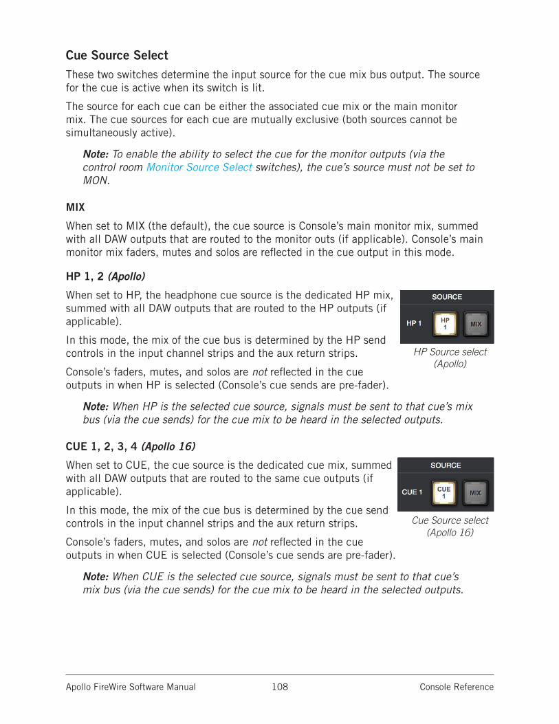
Apollo FireWire Software Manual Console Reference 108
Cue Source SelectThese two switches determine the input source for the cue mix bus output. The source for the cue is active when its switch is lit.
The source for each cue can be either the associated cue mix or the main monitor mix. The cue sources for each cue are mutually exclusive (both sources cannot be simultaneously active).
Note: To enable the ability to select the cue for the monitor outputs (via the control room Monitor Source Select switches), the cue’s source must not be set to MON.
MIX
When set to MIX (the default), the cue source is Console’s main monitor mix, summed with all DAW outputs that are routed to the monitor outs (if applicable). Console’s main monitor mix faders, mutes and solos are reflected in the cue output in this mode.
HP 1, 2 (Apollo)
When set to HP, the headphone cue source is the dedicated HP mix, summed with all DAW outputs that are routed to the HP outputs (if applicable).
In this mode, the mix of the cue bus is determined by the HP send controls in the input channel strips and the aux return strips.
Console’s faders, mutes, and solos are not reflected in the cue outputs in when HP is selected (Console’s cue sends are pre-fader).
Note: When HP is the selected cue source, signals must be sent to that cue’s mix bus (via the cue sends) for the cue mix to be heard in the selected outputs.
CUE 1, 2, 3, 4 (Apollo 16)
When set to CUE, the cue source is the dedicated cue mix, summed with all DAW outputs that are routed to the same cue outputs (if applicable).
In this mode, the mix of the cue bus is determined by the cue send controls in the input channel strips and the aux return strips.
Console’s faders, mutes, and solos are not reflected in the cue outputs in when CUE is selected (Console’s cue sends are pre-fader).
Note: When CUE is the selected cue source, signals must be sent to that cue’s mix bus (via the cue sends) for the cue mix to be heard in the selected outputs.
HP Source select (Apollo)
Cue Source select (Apollo 16)
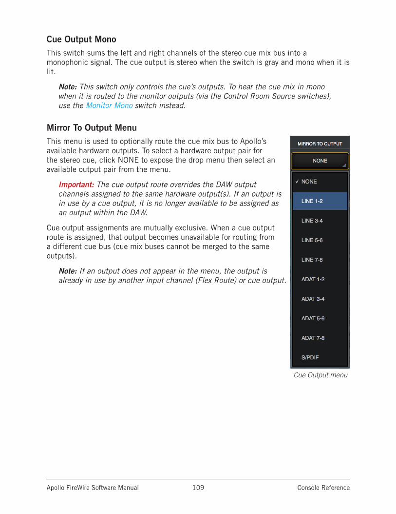
Apollo FireWire Software Manual Console Reference 109
Cue Output MonoThis switch sums the left and right channels of the stereo cue mix bus into a monophonic signal. The cue output is stereo when the switch is gray and mono when it is lit.
Note: This switch only controls the cue’s outputs. To hear the cue mix in mono when it is routed to the monitor outputs (via the Control Room Source switches), use the Monitor Mono switch instead.
Mirror To Output MenuThis menu is used to optionally route the cue mix bus to Apollo’s available hardware outputs. To select a hardware output pair for the stereo cue, click NONE to expose the drop menu then select an available output pair from the menu.
Important: The cue output route overrides the DAW output channels assigned to the same hardware output(s). If an output is in use by a cue output, it is no longer available to be assigned as an output within the DAW.
Cue output assignments are mutually exclusive. When a cue output route is assigned, that output becomes unavailable for routing from a different cue bus (cue mix buses cannot be merged to the same outputs).
Note: If an output does not appear in the menu, the output is already in use by another input channel (Flex Route) or cue output.
Cue Output menu
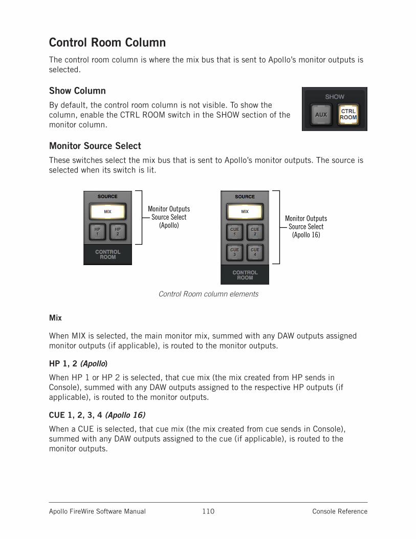
Apollo FireWire Software Manual Console Reference 110
Control Room ColumnThe control room column is where the mix bus that is sent to Apollo’s monitor outputs is selected.
Show ColumnBy default, the control room column is not visible. To show the column, enable the CTRL ROOM switch in the SHOW section of the monitor column.
Monitor Source SelectThese switches select the mix bus that is sent to Apollo’s monitor outputs. The source is selected when its switch is lit.
Control Room column elements
Mix
When MIX is selected, the main monitor mix, summed with any DAW outputs assigned monitor outputs (if applicable), is routed to the monitor outputs.
HP 1, 2 (Apollo)
When HP 1 or HP 2 is selected, that cue mix (the mix created from HP sends in Console), summed with any DAW outputs assigned to the respective HP outputs (if applicable), is routed to the monitor outputs.
CUE 1, 2, 3, 4 (Apollo 16)
When a CUE is selected, that cue mix (the mix created from cue sends in Console), summed with any DAW outputs assigned to the cue (if applicable), is routed to the monitor outputs.
Monitor OutputsSource Select
(Apollo)Monitor Outputs
Source Select(Apollo 16)
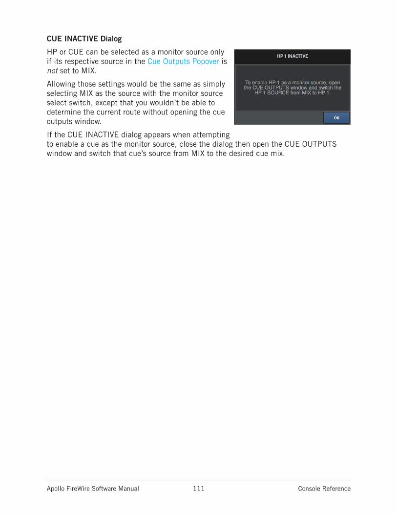
Apollo FireWire Software Manual Console Reference 111
CUE INACTIVE Dialog
HP or CUE can be selected as a monitor source only if its respective source in the Cue Outputs Popover is not set to MIX.
Allowing those settings would be the same as simply selecting MIX as the source with the monitor source select switch, except that you wouldn’t be able to determine the current route without opening the cue outputs window.
If the CUE INACTIVE dialog appears when attempting to enable a cue as the monitor source, close the dialog then open the CUE OUTPUTS window and switch that cue’s source from MIX to the desired cue mix.
Apollo FireWire Software Manual Console Reference 112
Console SessionsThe Sessions controls provide methods for managing complete Console configurations as session preset files. When a Console session file is saved, the current Console configuration is written to disk.
When a session file is subsequently reloaded, Console is returned to the exact same configuration state, regardless of any changes to Console that were made in the interim.
Content of Session FilesConsole session files contain most, but not all, Console settings. The specific parameters saved and not saved are listed below:
Saved – All knob, slider, and menu values, all inserted UAD plug-ins, settings contained within the plug-ins, and settings in Console Settings window (except those listed below).
Not saved – All Monitor Gain, Line Output Reference Levels, Clock Source, Sample Rate, Monitor Outputs Digital Mirror, and Cue Outputs settings are global parameters that are not session-specific. Most of these settings are managed in the Console Settings window.
Default Session Files LocationBy default, session files are saved to, and loaded from, the user’s home folder at:
• Mac: Users/UserName/Documents/Universal Audio/Sessions/• Windows: C:\Users\UserName\AppData\Roaming\Universal Audio\Sessions
Although session files can be saved to (and loaded from) any location on disk, using the default location enables the most convenience because Console always uses this location for the Sessions Manager window and also Open/Save dialogs presented by the OS.
Note: Session files must reside in the default location to appear in session lists within Console.
Sessions Sub-FoldersThe Session Files folder can contain one level of sub-folders for additional session organization capability. The contents of sub-folders (if any) are displayed in the SUB-FOLDER column when a folder in the SESSION column is selected.
Session Files SuffixConsole’s session files have the “.uadmix” suffix. The suffix is added to session files automatically when saving to disk; however, the suffix is not displayed in the file save dialog (the suffix should not be manually typed when saving a session file).
Note: Without the .uadmix suffix, the session files will not be visible in the “Open” file dialogs or the Sessions menu, and they won’t be opened when they are double-clicked in the OS file system.
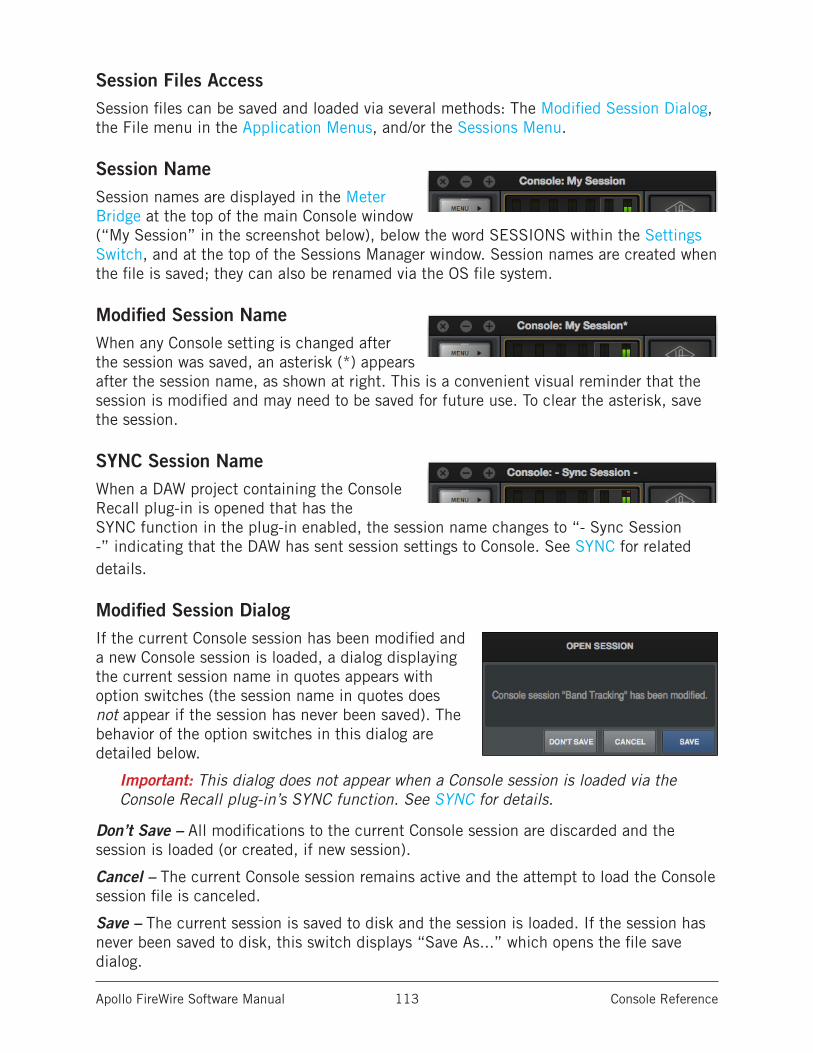
Apollo FireWire Software Manual Console Reference 113
Session Files AccessSession files can be saved and loaded via several methods: The Modified Session Dialog, the File menu in the Application Menus, and/or the Sessions Menu.
Session NameSession names are displayed in the Meter Bridge at the top of the main Console window (“My Session” in the screenshot below), below the word SESSIONS within the Settings Switch, and at the top of the Sessions Manager window. Session names are created when the file is saved; they can also be renamed via the OS file system.
Modified Session NameWhen any Console setting is changed after the session was saved, an asterisk (*) appears after the session name, as shown at right. This is a convenient visual reminder that the session is modified and may need to be saved for future use. To clear the asterisk, save the session.
SYNC Session NameWhen a DAW project containing the Console Recall plug-in is opened that has the SYNC function in the plug-in enabled, the session name changes to “- Sync Session -” indicating that the DAW has sent session settings to Console. See SYNC for related details.
Modified Session DialogIf the current Console session has been modified and a new Console session is loaded, a dialog displaying the current session name in quotes appears with option switches (the session name in quotes does not appear if the session has never been saved). The behavior of the option switches in this dialog are detailed below.
Important: This dialog does not appear when a Console session is loaded via the Console Recall plug-in’s SYNC function. See SYNC for details.
Don’t Save – All modifications to the current Console session are discarded and the session is loaded (or created, if new session).
Cancel – The current Console session remains active and the attempt to load the Console session file is canceled.
Save – The current session is saved to disk and the session is loaded. If the session has never been saved to disk, this switch displays “Save As...” which opens the file save dialog.
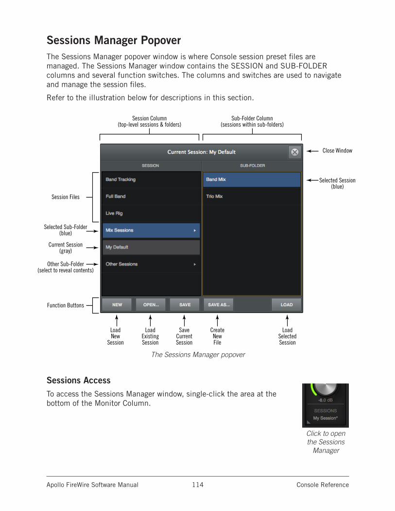
Apollo FireWire Software Manual Console Reference 114
Sessions Manager PopoverThe Sessions Manager popover window is where Console session preset files are managed. The Sessions Manager window contains the SESSION and SUB-FOLDER columns and several function switches. The columns and switches are used to navigate and manage the session files.
Refer to the illustration below for descriptions in this section.
The Sessions Manager popover
Sessions AccessTo access the Sessions Manager window, single-click the area at the bottom of the Monitor Column.
Close Window
Selected Session(blue)
Session Files
Current Session(gray)
Selected Sub-Folder(blue)
Other Sub-Folder(select to reveal contents)
LoadNew
Session
Session Column(top-level sessions & folders)
Sub-Folder Column(sessions within sub-folders)
LoadExistingSession
SaveCurrentSession
CreateNewFile
LoadSelectedSession
Function Buttons
Click to open the Sessions
Manager
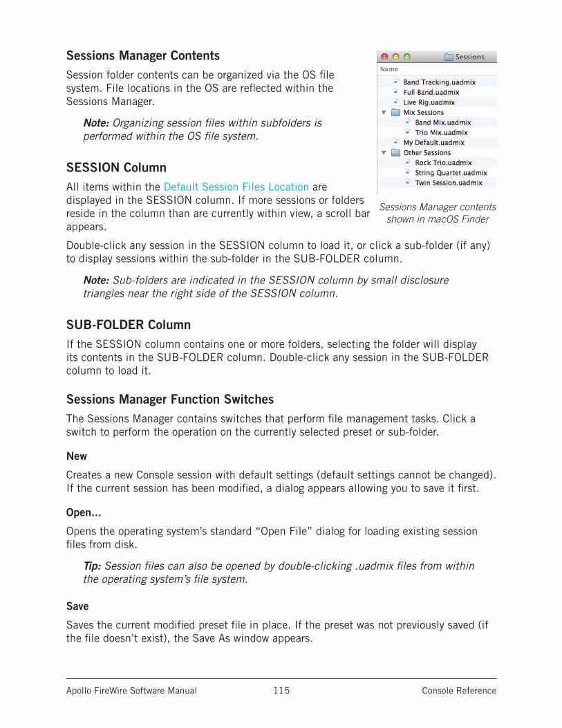
Apollo FireWire Software Manual Console Reference 115
Sessions Manager ContentsSession folder contents can be organized via the OS file system. File locations in the OS are reflected within the Sessions Manager.
Note: Organizing session files within subfolders is performed within the OS file system.
SESSION ColumnAll items within the Default Session Files Location are displayed in the SESSION column. If more sessions or folders reside in the column than are currently within view, a scroll bar appears.
Double-click any session in the SESSION column to load it, or click a sub-folder (if any) to display sessions within the sub-folder in the SUB-FOLDER column.
Note: Sub-folders are indicated in the SESSION column by small disclosure triangles near the right side of the SESSION column.
SUB-FOLDER ColumnIf the SESSION column contains one or more folders, selecting the folder will display its contents in the SUB-FOLDER column. Double-click any session in the SUB-FOLDER column to load it.
Sessions Manager Function SwitchesThe Sessions Manager contains switches that perform file management tasks. Click a switch to perform the operation on the currently selected preset or sub-folder.
New
Creates a new Console session with default settings (default settings cannot be changed). If the current session has been modified, a dialog appears allowing you to save it first.
Open...
Opens the operating system’s standard “Open File” dialog for loading existing session files from disk.
Tip: Session files can also be opened by double-clicking .uadmix files from within the operating system’s file system.
Save
Saves the current modified preset file in place. If the preset was not previously saved (if the file doesn’t exist), the Save As window appears.
Sessions Manager contents shown in macOS Finder
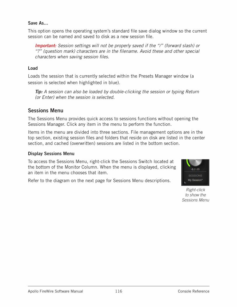
Apollo FireWire Software Manual Console Reference 116
Save As...
This option opens the operating system’s standard file save dialog window so the current session can be named and saved to disk as a new session file.
Important: Session settings will not be properly saved if the “/” (forward slash) or “?” (question mark) characters are in the filename. Avoid these and other special characters when saving session files.
Load
Loads the session that is currently selected within the Presets Manager window (a session is selected when highlighted in blue).
Tip: A session can also be loaded by double-clicking the session or typing Return (or Enter) when the session is selected.
Sessions MenuThe Sessions Menu provides quick access to sessions functions without opening the Sessions Manager. Click any item in the menu to perform the function.
Items in the menu are divided into three sections. File management options are in the top section, existing session files and folders that reside on disk are listed in the center section, and cached (overwritten) sessions are listed in the bottom section.
Display Sessions Menu
To access the Sessions Menu, right-click the Sessions Switch located at the bottom of the Monitor Column. When the menu is displayed, clicking an item in the menu chooses that item.
Refer to the diagram on the next page for Sessions Menu descriptions.
Right-click to show the
Sessions Menu
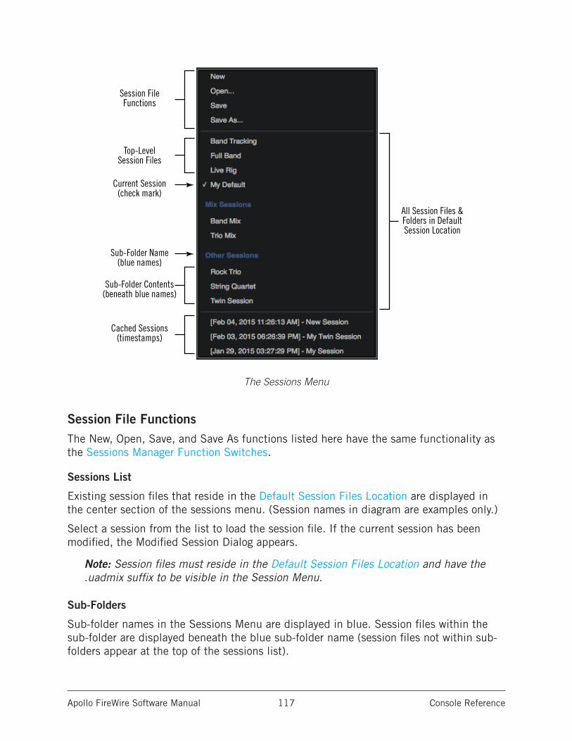
Apollo FireWire Software Manual Console Reference 117
The Sessions Menu
Session File FunctionsThe New, Open, Save, and Save As functions listed here have the same functionality as the Sessions Manager Function Switches.
Sessions List
Existing session files that reside in the Default Session Files Location are displayed in the center section of the sessions menu. (Session names in diagram are examples only.)
Select a session from the list to load the session file. If the current session has been modified, the Modified Session Dialog appears.
Note: Session files must reside in the Default Session Files Location and have the .uadmix suffix to be visible in the Session Menu.
Sub-Folders
Sub-folder names in the Sessions Menu are displayed in blue. Session files within the sub-folder are displayed beneath the blue sub-folder name (session files not within sub-folders appear at the top of the sessions list).
Top-LevelSession Files
All Session Files &Folders in Default Session Location
Current Session(check mark)
Sub-Folder Name(blue names)
Sub-Folder Contents(beneath blue names)
Cached Sessions(timestamps)
Session FileFunctions
Apollo FireWire Software Manual Console Reference 118
Cached SessionsCached sessions appear in the bottom section of the Sessions Menu. Cached sessions are the same as session files, except they don’t reside in session files on disk. Instead, these sessions are automatically created and stored in a temporary cache.
Why Cached Sessions Exist
When a DAW project containing the Console Recall plug-in is opened and the plug-in’s SYNC function is enabled, the Console settings contained in the DAW project overwrite the current Console settings. The cached sessions are used to recover the overwritten data if desired. See SYNC for details about the feature.
When Cached Sessions Appear
A cached session is automatically created every time a DAW project containing the Console Recall plug-in is opened and the plug-in’s SYNC function is enabled. In this scenario, the SYNC function loads the Console session contained in the DAW project, and the previously-active Console settings are moved into the cached sessions menu.
The previously-saved Console session’s filename is retained in the cached session, and a timestamp is prefixed so it can be easily distinguished from other sessions. The five most-recently cached sessions appear in the list.
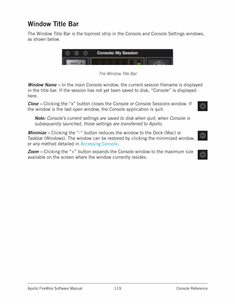
Apollo FireWire Software Manual Console Reference 119
Window Title BarThe Window Title Bar is the topmost strip in the Console and Console Settings windows, as shown below.
The Window Title Bar
Window Name – In the main Console window, the current session filename is displayed in the title bar. If the session has not yet been saved to disk, “Console” is displayed here.
Close – Clicking the “x” button closes the Console or Console Sessions window. If the window is the last open window, the Console application is quit.
Note: Console’s current settings are saved to disk when quit; when Console is subsequently launched, those settings are transferred to Apollo.
Minimize – Clicking the “-” button reduces the window to the Dock (Mac) or Taskbar (Windows). The window can be restored by clicking the minimized window, or any method detailed in Accessing Console.
Zoom – Clicking the “+” button expands the Console window to the maximum size available on the screen where the window currently resides.
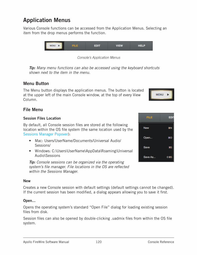
Apollo FireWire Software Manual Console Reference 120
Application MenusVarious Console functions can be accessed from the Application Menus. Selecting an item from the drop menus performs the function.
Console’s Application Menus
Tip: Many menu functions can also be accessed using the keyboard shortcuts shown next to the item in the menu.
Menu ButtonThe Menu button displays the application menus. The button is located at the upper left of the main Console window, at the top of every View Column.
File Menu
Session Files Location
By default, all Console session files are stored at the following location within the OS file system (the same location used by the Sessions Manager Popover):
• Mac: Users/UserName/Documents/Universal Audio/Sessions/
• Windows: C:\Users\UserName\AppData\Roaming\Universal Audio\Sessions
Tip: Console sessions can be organized via the operating system’s file manager. File locations in the OS are reflected within the Sessions Manager.
New
Creates a new Console session with default settings (default settings cannot be changed). If the current session has been modified, a dialog appears allowing you to save it first.
Open...
Opens the operating system’s standard “Open File” dialog for loading existing session files from disk.
Session files can also be opened by double-clicking .uadmix files from within the OS file system.
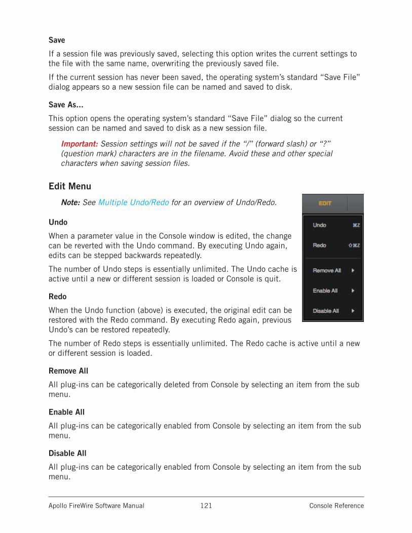
Apollo FireWire Software Manual Console Reference 121
Save
If a session file was previously saved, selecting this option writes the current settings to the file with the same name, overwriting the previously saved file.
If the current session has never been saved, the operating system’s standard “Save File” dialog appears so a new session file can be named and saved to disk.
Save As...
This option opens the operating system’s standard “Save File” dialog so the current session can be named and saved to disk as a new session file.
Important: Session settings will not be saved if the “/” (forward slash) or “?” (question mark) characters are in the filename. Avoid these and other special characters when saving session files.
Edit Menu
Note: See Multiple Undo/Redo for an overview of Undo/Redo.
Undo
When a parameter value in the Console window is edited, the change can be reverted with the Undo command. By executing Undo again, edits can be stepped backwards repeatedly.
The number of Undo steps is essentially unlimited. The Undo cache is active until a new or different session is loaded or Console is quit.
Redo
When the Undo function (above) is executed, the original edit can be restored with the Redo command. By executing Redo again, previous Undo’s can be restored repeatedly.
The number of Redo steps is essentially unlimited. The Redo cache is active until a new or different session is loaded.
Remove All
All plug-ins can be categorically deleted from Console by selecting an item from the sub menu.
Enable All
All plug-ins can be categorically enabled from Console by selecting an item from the sub menu.
Disable All
All plug-ins can be categorically enabled from Console by selecting an item from the sub menu.
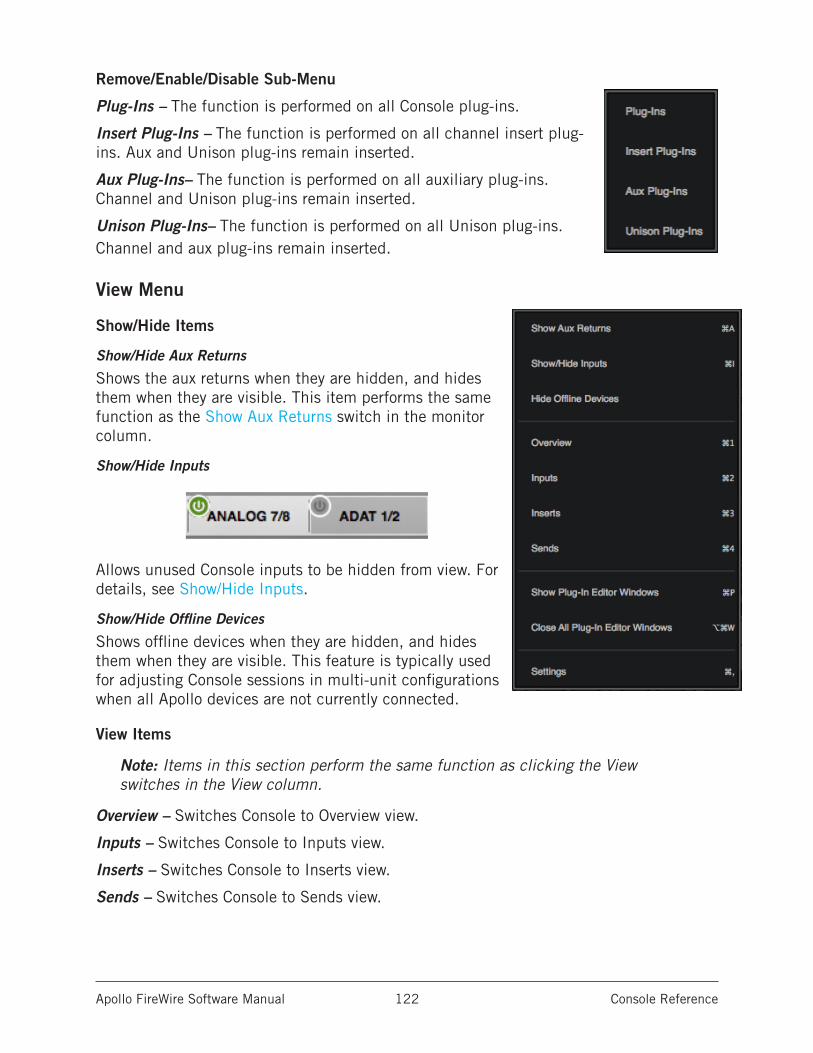
Apollo FireWire Software Manual Console Reference 122
Remove/Enable/Disable Sub-Menu
Plug-Ins – The function is performed on all Console plug-ins.
Insert Plug-Ins – The function is performed on all channel insert plug-ins. Aux and Unison plug-ins remain inserted.
Aux Plug-Ins– The function is performed on all auxiliary plug-ins. Channel and Unison plug-ins remain inserted.
Unison Plug-Ins– The function is performed on all Unison plug-ins. Channel and aux plug-ins remain inserted.
View Menu
Show/Hide Items
Show/Hide Aux Returns
Shows the aux returns when they are hidden, and hides them when they are visible. This item performs the same function as the Show Aux Returns switch in the monitor column.
Show/Hide Inputs
Allows unused Console inputs to be hidden from view. For details, see Show/Hide Inputs.
Show/Hide Offline Devices
Shows offline devices when they are hidden, and hides them when they are visible. This feature is typically used for adjusting Console sessions in multi-unit configurations when all Apollo devices are not currently connected.
View Items
Note: Items in this section perform the same function as clicking the View switches in the View column.
Overview – Switches Console to Overview view.
Inputs – Switches Console to Inputs view.
Inserts – Switches Console to Inserts view.
Sends – Switches Console to Sends view.
Apollo FireWire Software Manual Console Reference 123
Show Plug-In Editor Windows
Brings all open UAD plug-in editor windows to the foreground (if any). If ALWAYS ON TOP in the Display panel within the Console Settings window is set to PLUG-INS, this function has no effect (plug-in editors are always in the foreground in this mode).
Note: This item applies only to UAD plug-ins used within Console, not those used within a DAW.
Close All Plug-In Editor Windows
Closes all open UAD plug-in editor windows (if any).
Settings
Opens the Console Settings window, where various global parameters are configured. See Sessions Manager Popover for details about the window.
Help Menu
Documentation
This item opens the local folder containing all Apollo product documentation files. Consult the documentation when you need specific operational information.
After opening the folder, double-click a documentation file to open it.
Tip: Use the search function within the PDF reader application to quickly find information about a particular topic.
Contents of the documentation folder:
• Apollo Software Manuals (one for each connection protocol)• Apollo Hardware Manuals (one for each unique hardware model)• UAD System Manual• UAD Plug-Ins Manual• Direct Developer (3rd-party) plug-in manuals
Note: For related information, see the Apollo Documentation Overview.
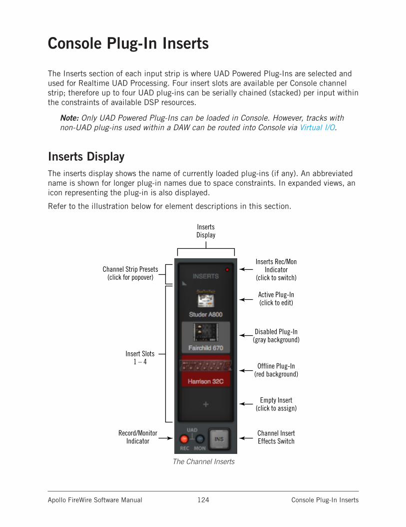
Apollo FireWire Software Manual Console Plug-In Inserts 124
Console Plug-In Inserts
The Inserts section of each input strip is where UAD Powered Plug-Ins are selected and used for Realtime UAD Processing. Four insert slots are available per Console channel strip; therefore up to four UAD plug-ins can be serially chained (stacked) per input within the constraints of available DSP resources.
Note: Only UAD Powered Plug-Ins can be loaded in Console. However, tracks with non-UAD plug-ins used within a DAW can be routed into Console via Virtual I/O.
Inserts DisplayThe inserts display shows the name of currently loaded plug-ins (if any). An abbreviated name is shown for longer plug-in names due to space constraints. In expanded views, an icon representing the plug-in is also displayed.
Refer to the illustration below for element descriptions in this section.
The Channel Inserts
Inserts Rec/MonIndicator
(click to switch)
Record/MonitorIndicator
Channel Strip Presets(click for popover)
Insert Slots1 – 4
Disabled Plug-In(gray background)
Empty Insert(click to assign)
Channel InsertEffects Switch
Offline Plug-In(red background)
Active Plug-In(click to edit)
InsertsDisplay
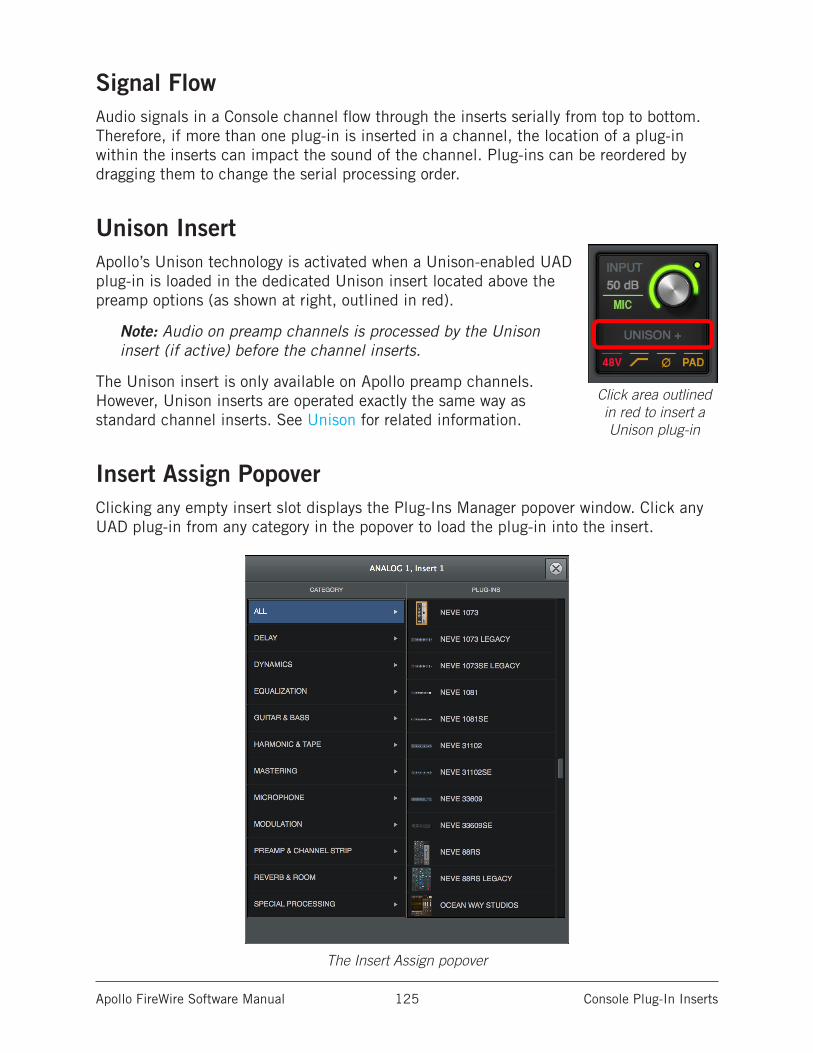
Apollo FireWire Software Manual Console Plug-In Inserts 125
Signal FlowAudio signals in a Console channel flow through the inserts serially from top to bottom. Therefore, if more than one plug-in is inserted in a channel, the location of a plug-in within the inserts can impact the sound of the channel. Plug-ins can be reordered by dragging them to change the serial processing order.
Unison InsertApollo’s Unison technology is activated when a Unison-enabled UAD plug-in is loaded in the dedicated Unison insert located above the preamp options (as shown at right, outlined in red).
Note: Audio on preamp channels is processed by the Unison insert (if active) before the channel inserts.
The Unison insert is only available on Apollo preamp channels. However, Unison inserts are operated exactly the same way as standard channel inserts. See Unison for related information.
Insert Assign PopoverClicking any empty insert slot displays the Plug-Ins Manager popover window. Click any UAD plug-in from any category in the popover to load the plug-in into the insert.
The Insert Assign popover
Click area outlined in red to insert a Unison plug-in
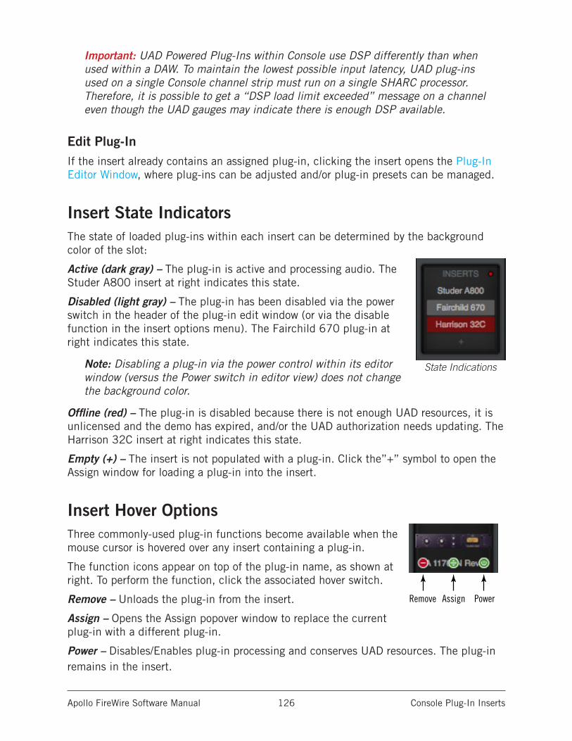
Apollo FireWire Software Manual Console Plug-In Inserts 126
Important: UAD Powered Plug-Ins within Console use DSP differently than when used within a DAW. To maintain the lowest possible input latency, UAD plug-ins used on a single Console channel strip must run on a single SHARC processor. Therefore, it is possible to get a “DSP load limit exceeded” message on a channel even though the UAD gauges may indicate there is enough DSP available.
Edit Plug-InIf the insert already contains an assigned plug-in, clicking the insert opens the Plug-In Editor Window, where plug-ins can be adjusted and/or plug-in presets can be managed.
Insert State IndicatorsThe state of loaded plug-ins within each insert can be determined by the background color of the slot:
Active (dark gray) – The plug-in is active and processing audio. The Studer A800 insert at right indicates this state.
Disabled (light gray) – The plug-in has been disabled via the power switch in the header of the plug-in edit window (or via the disable function in the insert options menu). The Fairchild 670 plug-in at right indicates this state.
Note: Disabling a plug-in via the power control within its editor window (versus the Power switch in editor view) does not change the background color.
Offline (red) – The plug-in is disabled because there is not enough UAD resources, it is unlicensed and the demo has expired, and/or the UAD authorization needs updating. The Harrison 32C insert at right indicates this state.
Empty (+) – The insert is not populated with a plug-in. Click the”+” symbol to open the Assign window for loading a plug-in into the insert.
Insert Hover OptionsThree commonly-used plug-in functions become available when the mouse cursor is hovered over any insert containing a plug-in.
The function icons appear on top of the plug-in name, as shown at right. To perform the function, click the associated hover switch.
Remove – Unloads the plug-in from the insert.
Assign – Opens the Assign popover window to replace the current plug-in with a different plug-in.
Power – Disables/Enables plug-in processing and conserves UAD resources. The plug-in remains in the insert.
State Indications
Remove Assign Power
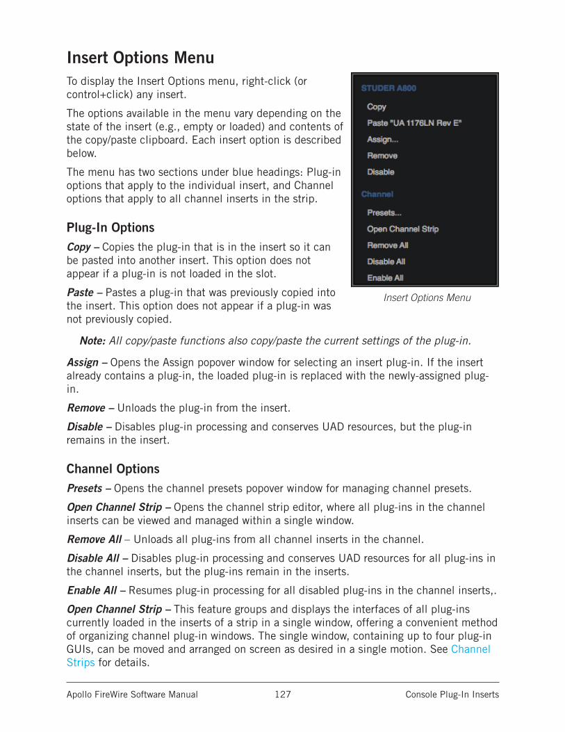
Apollo FireWire Software Manual Console Plug-In Inserts 127
Insert Options MenuTo display the Insert Options menu, right-click (or control+click) any insert.
The options available in the menu vary depending on the state of the insert (e.g., empty or loaded) and contents of the copy/paste clipboard. Each insert option is described below.
The menu has two sections under blue headings: Plug-in options that apply to the individual insert, and Channel options that apply to all channel inserts in the strip.
Plug-In OptionsCopy – Copies the plug-in that is in the insert so it can be pasted into another insert. This option does not appear if a plug-in is not loaded in the slot.
Paste – Pastes a plug-in that was previously copied into the insert. This option does not appear if a plug-in was not previously copied.
Note: All copy/paste functions also copy/paste the current settings of the plug-in.
Assign – Opens the Assign popover window for selecting an insert plug-in. If the insert already contains a plug-in, the loaded plug-in is replaced with the newly-assigned plug-in.
Remove – Unloads the plug-in from the insert.
Disable – Disables plug-in processing and conserves UAD resources, but the plug-in remains in the insert.
Channel OptionsPresets – Opens the channel presets popover window for managing channel presets.
Open Channel Strip – Opens the channel strip editor, where all plug-ins in the channel inserts can be viewed and managed within a single window.
Remove All – Unloads all plug-ins from all channel inserts in the channel.
Disable All – Disables plug-in processing and conserves UAD resources for all plug-ins in the channel inserts, but the plug-ins remain in the inserts.
Enable All – Resumes plug-in processing for all disabled plug-ins in the channel inserts,.
Open Channel Strip – This feature groups and displays the interfaces of all plug-ins currently loaded in the inserts of a strip in a single window, offering a convenient method of organizing channel plug-in windows. The single window, containing up to four plug-in GUIs, can be moved and arranged on screen as desired in a single motion. See Channel Strips for details.
Insert Options Menu
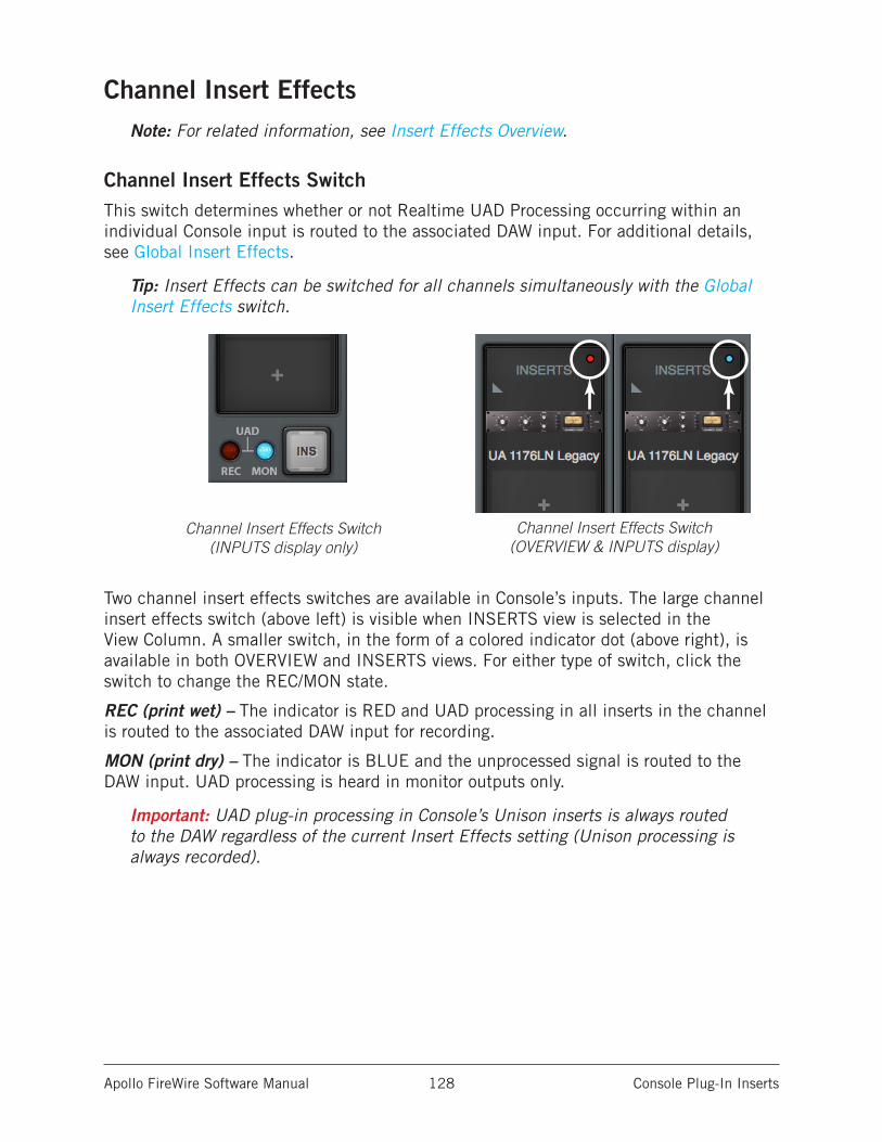
Apollo FireWire Software Manual Console Plug-In Inserts 128
Channel Insert EffectsNote: For related information, see Insert Effects Overview.
Channel Insert Effects SwitchThis switch determines whether or not Realtime UAD Processing occurring within an individual Console input is routed to the associated DAW input. For additional details, see Global Insert Effects.
Tip: Insert Effects can be switched for all channels simultaneously with the Global Insert Effects switch.
Two channel insert effects switches are available in Console’s inputs. The large channel insert effects switch (above left) is visible when INSERTS view is selected in the View Column. A smaller switch, in the form of a colored indicator dot (above right), is available in both OVERVIEW and INSERTS views. For either type of switch, click the switch to change the REC/MON state.
REC (print wet) – The indicator is RED and UAD processing in all inserts in the channel is routed to the associated DAW input for recording.
MON (print dry) – The indicator is BLUE and the unprocessed signal is routed to the DAW input. UAD processing is heard in monitor outputs only.
Important: UAD plug-in processing in Console’s Unison inserts is always routed to the DAW regardless of the current Insert Effects setting (Unison processing is always recorded).
Channel Insert Effects Switch (INPUTS display only)
Channel Insert Effects Switch (OVERVIEW & INPUTS display)
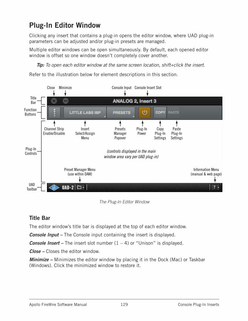
Apollo FireWire Software Manual Console Plug-In Inserts 129
Plug-In Editor WindowClicking any insert that contains a plug-in opens the editor window, where UAD plug-in parameters can be adjusted and/or plug-in presets are managed.
Multiple editor windows can be open simultaneously. By default, each opened editor window is offset so one window doesn’t completely cover another.
Tip: To open each editor window at the same screen location, shift+click the insert.
Refer to the illustration below for element descriptions in this section.
The Plug-In Editor Window
Title BarThe editor window’s title bar is displayed at the top of each editor window.
Console Input – The Console input containing the insert is displayed.
Console Insert – The insert slot number (1 – 4) or “Unison” is displayed.
Close – Closes the editor window.
Minimize – Minimizes the editor window by placing it in the Dock (Mac) or Taskbar (Windows). Click the minimized window to restore it.
FunctionButtons
TitleBar
Close Minimize Console Input Console Insert Slot
UADToolbar
(controls displayed in the mainwindow area vary per UAD plug-in)
Channel StripEnable/Disable
InsertSelect/Assign
Menu
Plug-InControls
PresetsManagerPopover
Preset Manager Menu(use within DAW)
Information Menu(manual & web page)
Plug-InPower
CopyPlug-InSettings
PastePlug-InSettings
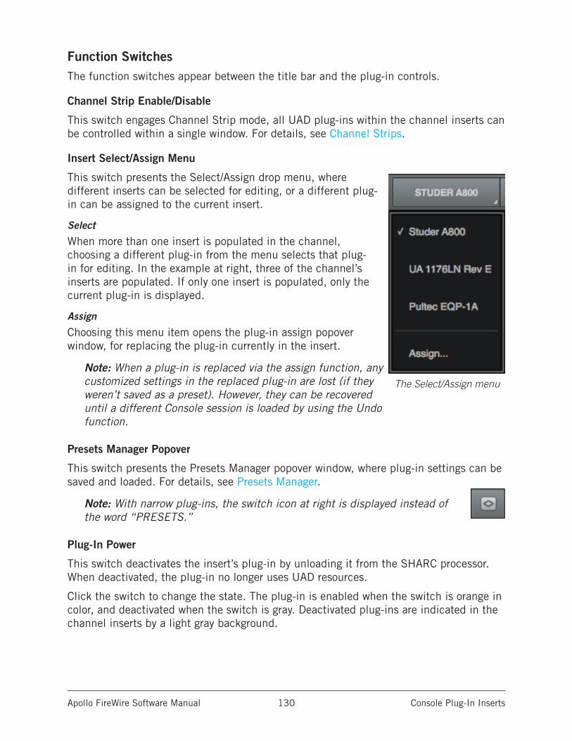
Apollo FireWire Software Manual Console Plug-In Inserts 130
Function SwitchesThe function switches appear between the title bar and the plug-in controls.
Channel Strip Enable/Disable
This switch engages Channel Strip mode, all UAD plug-ins within the channel inserts can be controlled within a single window. For details, see Channel Strips.
Insert Select/Assign Menu
This switch presents the Select/Assign drop menu, where different inserts can be selected for editing, or a different plug-in can be assigned to the current insert.
Select
When more than one insert is populated in the channel, choosing a different plug-in from the menu selects that plug-in for editing. In the example at right, three of the channel’s inserts are populated. If only one insert is populated, only the current plug-in is displayed.
Assign
Choosing this menu item opens the plug-in assign popover window, for replacing the plug-in currently in the insert.
Note: When a plug-in is replaced via the assign function, any customized settings in the replaced plug-in are lost (if they weren’t saved as a preset). However, they can be recovered until a different Console session is loaded by using the Undo function.
Presets Manager Popover
This switch presents the Presets Manager popover window, where plug-in settings can be saved and loaded. For details, see Presets Manager.
Note: With narrow plug-ins, the switch icon at right is displayed instead of the word “PRESETS.”
Plug-In Power
This switch deactivates the insert’s plug-in by unloading it from the SHARC processor. When deactivated, the plug-in no longer uses UAD resources.
Click the switch to change the state. The plug-in is enabled when the switch is orange in color, and deactivated when the switch is gray. Deactivated plug-ins are indicated in the channel inserts by a light gray background.
The Select/Assign menu
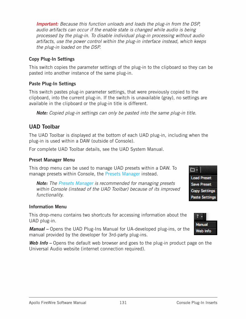
Apollo FireWire Software Manual Console Plug-In Inserts 131
Important: Because this function unloads and loads the plug-in from the DSP, audio artifacts can occur if the enable state is changed while audio is being processed by the plug-in. To disable individual plug-in processing without audio artifacts, use the power control within the plug-in interface instead, which keeps the plug-in loaded on the DSP.
Copy Plug-In Settings
This switch copies the parameter settings of the plug-in to the clipboard so they can be pasted into another instance of the same plug-in.
Paste Plug-In Settings
This switch pastes plug-in parameter settings, that were previously copied to the clipboard, into the current plug-in. If the switch is unavailable (gray), no settings are available in the clipboard or the plug-in title is different.
Note: Copied plug-in settings can only be pasted into the same plug-in title.
UAD ToolbarThe UAD Toolbar is displayed at the bottom of each UAD plug-in, including when the plug-in is used within a DAW (outside of Console).
For complete UAD Toolbar details, see the UAD System Manual.
Preset Manager Menu
This drop menu can be used to manage UAD presets within a DAW. To manage presets within Console, the Presets Manager instead.
Note: The Presets Manager is recommended for managing presets within Console (instead of the UAD Toolbar) because of its improved functionality.
Information Menu
This drop-menu contains two shortcuts for accessing information about the UAD plug-in.
Manual – Opens the UAD Plug-Ins Manual for UA-developed plug-ins, or the manual provided by the developer for 3rd-party plug-ins.
Web Info – Opens the default web browser and goes to the plug-in product page on the Universal Audio website (internet connection required).
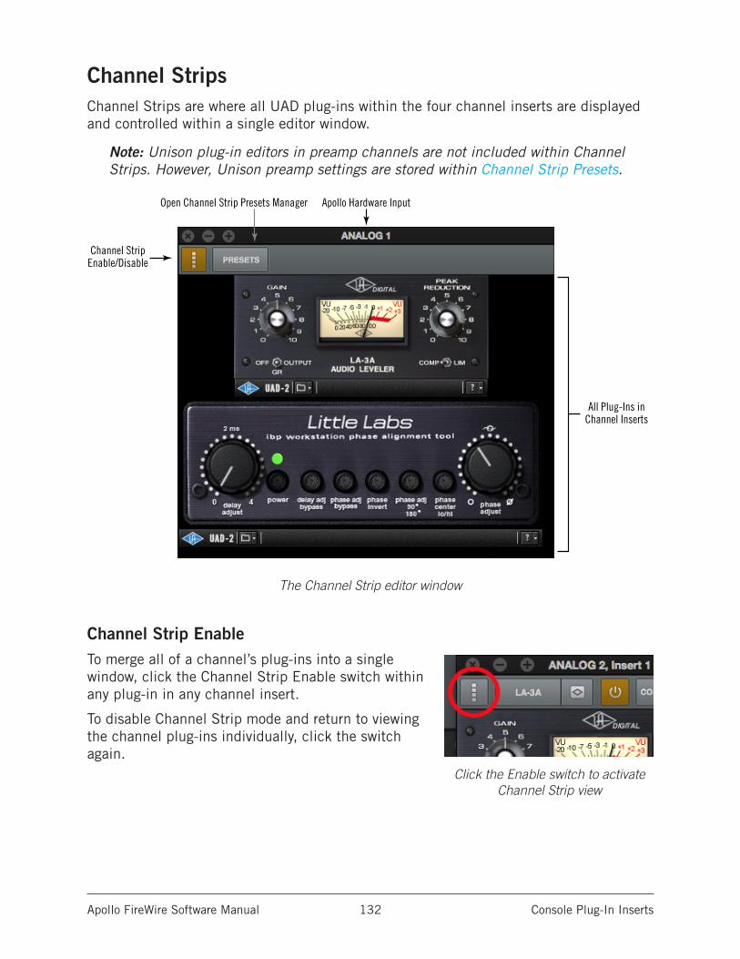
Apollo FireWire Software Manual Console Plug-In Inserts 132
Channel StripsChannel Strips are where all UAD plug-ins within the four channel inserts are displayed and controlled within a single editor window.
Note: Unison plug-in editors in preamp channels are not included within Channel Strips. However, Unison preamp settings are stored within Channel Strip Presets.
The Channel Strip editor window
Channel Strip EnableTo merge all of a channel’s plug-ins into a single window, click the Channel Strip Enable switch within any plug-in in any channel insert.
To disable Channel Strip mode and return to viewing the channel plug-ins individually, click the switch again.
Apollo Hardware Input
Channel StripEnable/Disable
Open Channel Strip Presets Manager
All Plug-Ins inChannel Inserts
Click the Enable switch to activate Channel Strip view
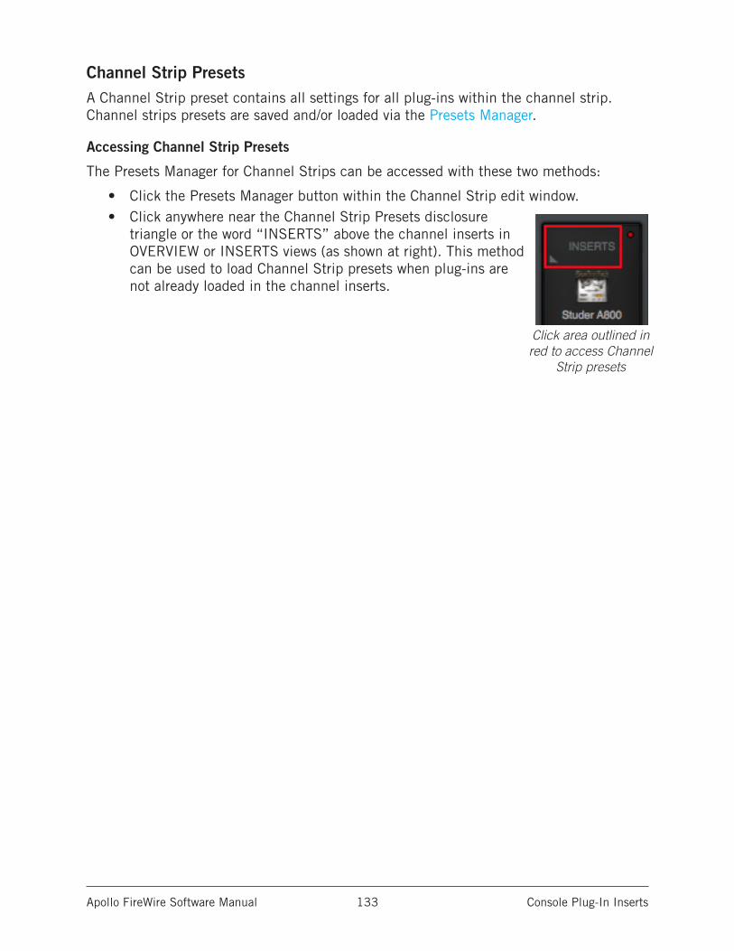
Apollo FireWire Software Manual Console Plug-In Inserts 133
Channel Strip PresetsA Channel Strip preset contains all settings for all plug-ins within the channel strip. Channel strips presets are saved and/or loaded via the Presets Manager.
Accessing Channel Strip Presets
The Presets Manager for Channel Strips can be accessed with these two methods:
• Click the Presets Manager button within the Channel Strip edit window.• Click anywhere near the Channel Strip Presets disclosure
triangle or the word “INSERTS” above the channel inserts in OVERVIEW or INSERTS views (as shown at right). This method can be used to load Channel Strip presets when plug-ins are not already loaded in the channel inserts.
Click area outlined in red to access Channel
Strip presets
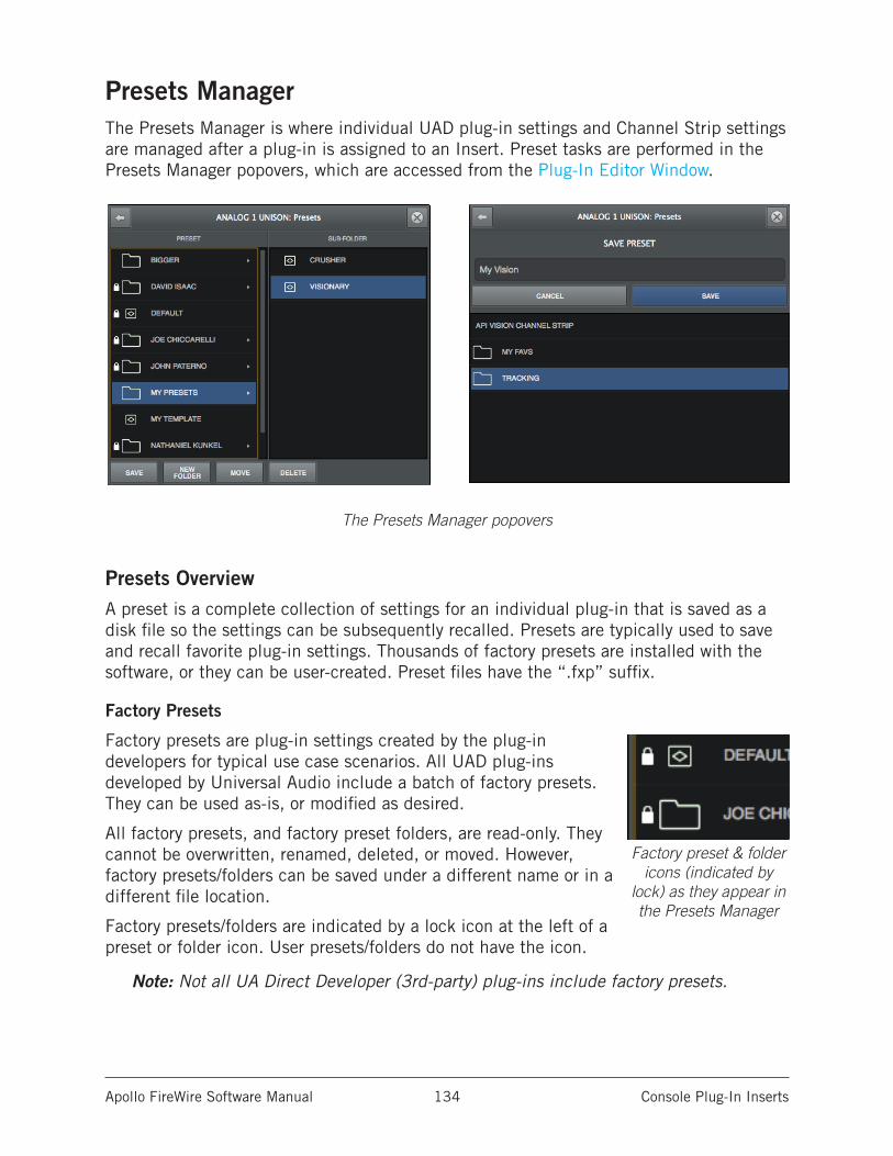
Apollo FireWire Software Manual Console Plug-In Inserts 134
Presets ManagerThe Presets Manager is where individual UAD plug-in settings and Channel Strip settings are managed after a plug-in is assigned to an Insert. Preset tasks are performed in the Presets Manager popovers, which are accessed from the Plug-In Editor Window.
The Presets Manager popovers
Presets OverviewA preset is a complete collection of settings for an individual plug-in that is saved as a disk file so the settings can be subsequently recalled. Presets are typically used to save and recall favorite plug-in settings. Thousands of factory presets are installed with the software, or they can be user-created. Preset files have the “.fxp” suffix.
Factory Presets
Factory presets are plug-in settings created by the plug-in developers for typical use case scenarios. All UAD plug-ins developed by Universal Audio include a batch of factory presets. They can be used as-is, or modified as desired.
All factory presets, and factory preset folders, are read-only. They cannot be overwritten, renamed, deleted, or moved. However, factory presets/folders can be saved under a different name or in a different file location.
Factory presets/folders are indicated by a lock icon at the left of a preset or folder icon. User presets/folders do not have the icon.
Note: Not all UA Direct Developer (3rd-party) plug-ins include factory presets.
Factory preset & folder icons (indicated by
lock) as they appear in the Presets Manager
Apollo FireWire Software Manual Console Plug-In Inserts 135
Presets Folder Location
All factory and user preset files for UAD plug-ins are stored at the following location within the operating system:
• Mac: /Library/Application Support/Universal Audio/Presets• Windows: C:\Program Files (x86)\Universal Audio\Powered Plugins\Presets
Tip: User presets and folders can be organized via the operating system’s file manager (e.g., macOS Finder or Windows Explorer). File locations in the operating system are reflected within the Presets Manager.
Plug-In’s Presets Folder
Inside the Presets folder above are folders named with the title of each UAD plug-in. Each of these folders contain all factory and user presets for that particular plug-in. This is the plug-in’s presets folder. The contents of this folder is displayed in the PRESET column within the Presets Manager.
Note: User presets can only be saved to the plug-in’s presets folder.
Presets Sub-Folders
Each plug-in’s presets folder can contain one level of sub-folders for additional preset organization capability. The contents of sub-folders (if any) are displayed in the SUB-FOLDER column when a folder in the PRESET column is selected.
Apollo FireWire Software Manual Console Plug-In Inserts 136
Channel Strip PresetsA Channel Strip preset is a complete collection of plug-ins within a single channel, and all parameter settings within those plug-ins, that is saved as a disk file so the channel strip preset can be subsequently recalled into the same or a different channel. Channel strip preset files have the “.uadchannel” suffix.
Tip: To activate Channel Strip view, click the Channel Strip icon in the Edit Window. Channel Strip mode is active when the switch is orange colored.
Channel Strip Presets Folder
All Channel Strip presets reside in the Channel Strips presets folder. The contents of this folder is displayed in the PRESET column within the Presets Manager.
Note: Channel Strip presets can only be saved to the Channel Strip presets folder.
Channel Strip Presets Folder Location
All Channel Strip files are stored at the following location within the operating system:
Mac:
/Library/Application Support/Universal Audio/Presets/Channel Strip
Windows:
C:\Program Files (x86)\Universal Audio\Powered Plugins\Presets\Channel Strip
Tip: User presets and folders can be organized via the operating system’s file manager (e.g., macOS Finder or Windows Explorer). File locations in the operating system are reflected within the Presets Manager.
Channel Strip Presets Sub-Folders
The Channel Strip presets folder can contain one level of sub-folders for additional channel strip preset organization capability. The contents of sub-folders (if any) is displayed in the SUB-FOLDER column when a folder in the CHANNEL PRESET column is selected.
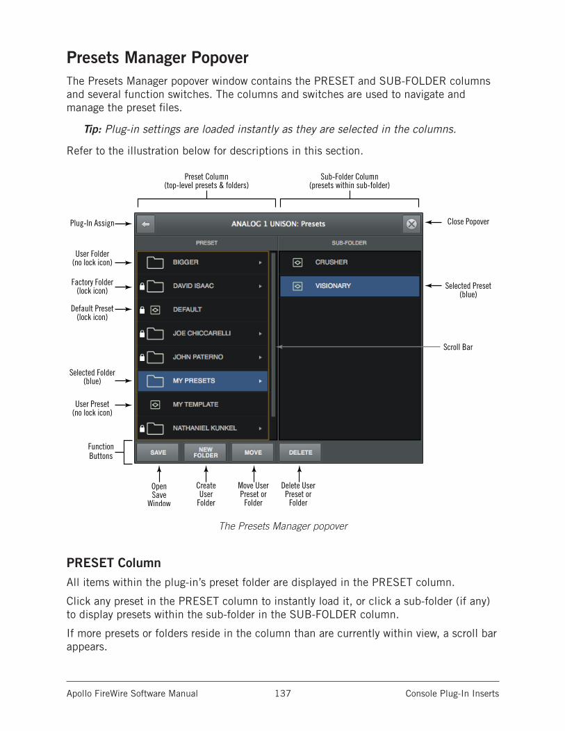
Apollo FireWire Software Manual Console Plug-In Inserts 137
Presets Manager PopoverThe Presets Manager popover window contains the PRESET and SUB-FOLDER columns and several function switches. The columns and switches are used to navigate and manage the preset files.
Tip: Plug-in settings are loaded instantly as they are selected in the columns.
Refer to the illustration below for descriptions in this section.
The Presets Manager popover
PRESET ColumnAll items within the plug-in’s preset folder are displayed in the PRESET column.
Click any preset in the PRESET column to instantly load it, or click a sub-folder (if any) to display presets within the sub-folder in the SUB-FOLDER column.
If more presets or folders reside in the column than are currently within view, a scroll bar appears.
Close Popover
Selected Preset(blue)
Scroll Bar
Plug-In Assign
User Folder(no lock icon)
Factory Folder(lock icon)
Default Preset(lock icon)
Selected Folder(blue)
User Preset(no lock icon)
Open Save
Window
Preset Column(top-level presets & folders)
Sub-Folder Column(presets within sub-folder)
Create User
Folder
Move User Preset or
Folder
Delete User Preset or
Folder
FunctionButtons
Apollo FireWire Software Manual Console Plug-In Inserts 138
SUB-FOLDER ColumnIf the PRESET column contains one or more folders, selecting the folder will display its contents in the SUB-FOLDER column. Click any preset in the SUB-FOLDER column to instantly load it.
If more presets reside in the column than are currently within view, a scroll bar appears.
Presets Manager Function ButtonsThe Presets Manager contains switches to name, save, and perform other file management tasks. Click a switch to perform the operation on the currently selected preset or sub-folder.
Save – Saves the current modified preset file in place. If the preset was not previously saved (if the file doesn’t exist), the Save window appears.
New Folder – Creates a new sub-folder. Sub-folders appear in the left column of the Presets Manager.
Move – Opens the Save window where the selected preset can be moved to a different location within the presets folder, with the option to rename the preset.
Delete – Deletes the selected preset file from disk and removes it from the presets list. A confirmation dialog appears before the file is deleted.
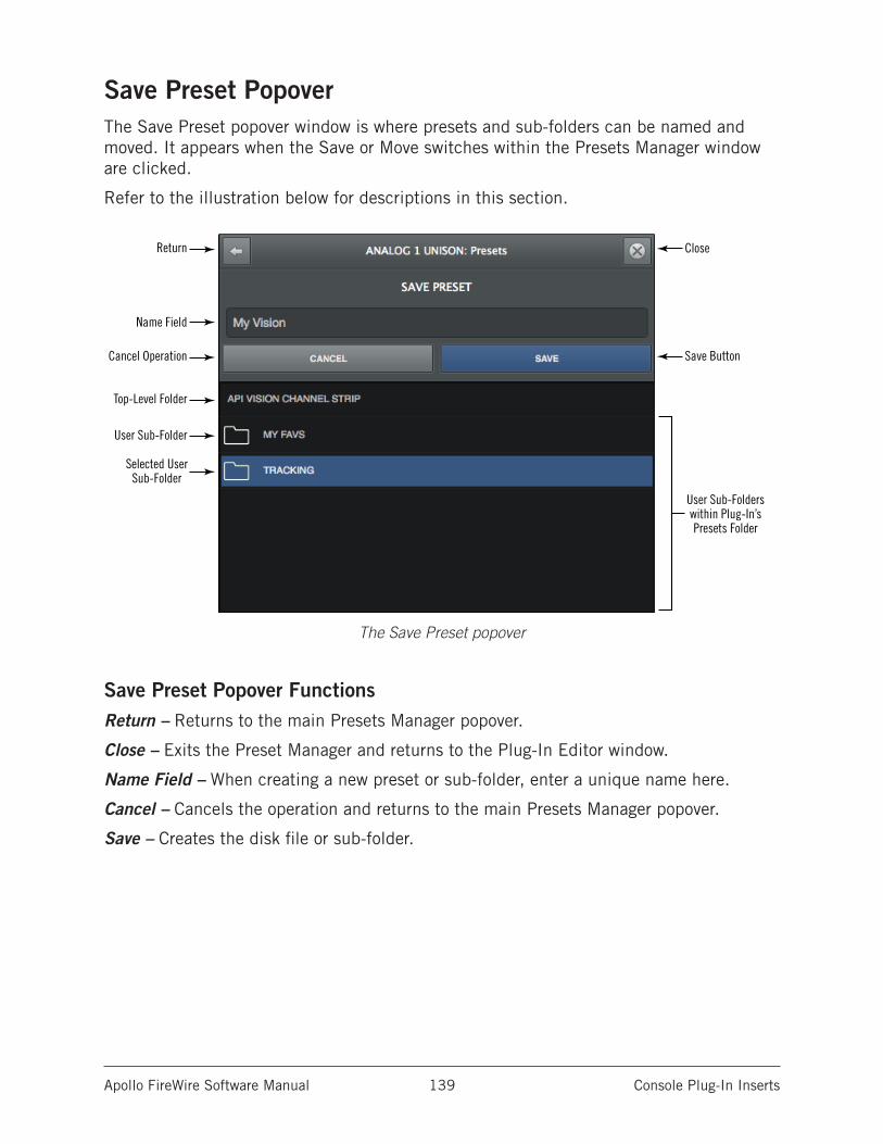
Apollo FireWire Software Manual Console Plug-In Inserts 139
Save Preset PopoverThe Save Preset popover window is where presets and sub-folders can be named and moved. It appears when the Save or Move switches within the Presets Manager window are clicked.
Refer to the illustration below for descriptions in this section.
The Save Preset popover
Save Preset Popover FunctionsReturn – Returns to the main Presets Manager popover.
Close – Exits the Preset Manager and returns to the Plug-In Editor window.
Name Field – When creating a new preset or sub-folder, enter a unique name here.
Cancel – Cancels the operation and returns to the main Presets Manager popover.
Save – Creates the disk file or sub-folder.
Return
Cancel Operation
User Sub-Folders within Plug-In’s Presets Folder
Name Field
Close
Top-Level Folder
User Sub-Folder
Selected UserSub-Folder
Save Button
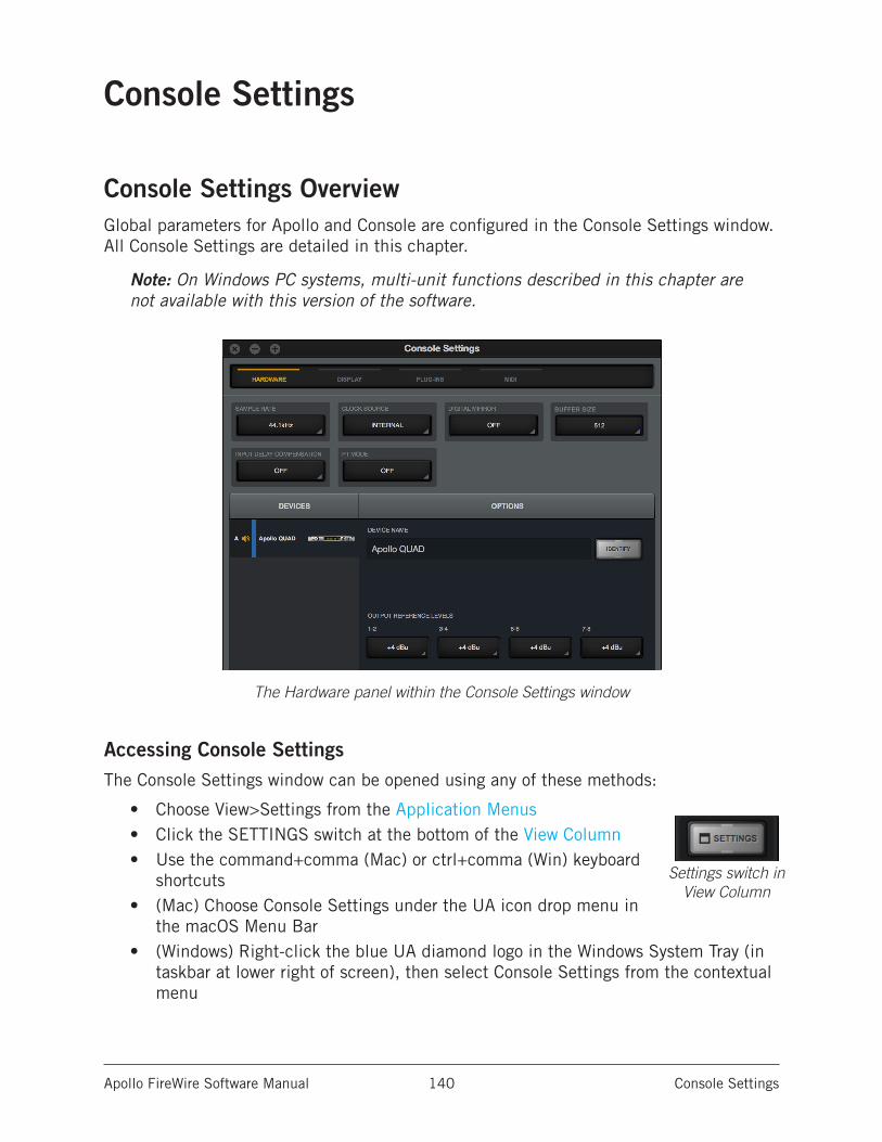
Apollo FireWire Software Manual Console Settings 140
Console Settings
Console Settings OverviewGlobal parameters for Apollo and Console are configured in the Console Settings window. All Console Settings are detailed in this chapter.
Note: On Windows PC systems, multi-unit functions described in this chapter are not available with this version of the software.
The Hardware panel within the Console Settings window
Accessing Console SettingsThe Console Settings window can be opened using any of these methods:
• Choose View>Settings from the Application Menus• Click the SETTINGS switch at the bottom of the View Column• Use the command+comma (Mac) or ctrl+comma (Win) keyboard
shortcuts• (Mac) Choose Console Settings under the UA icon drop menu in
the macOS Menu Bar• (Windows) Right-click the blue UA diamond logo in the Windows System Tray (in
taskbar at lower right of screen), then select Console Settings from the contextual menu
Settings switch in View Column
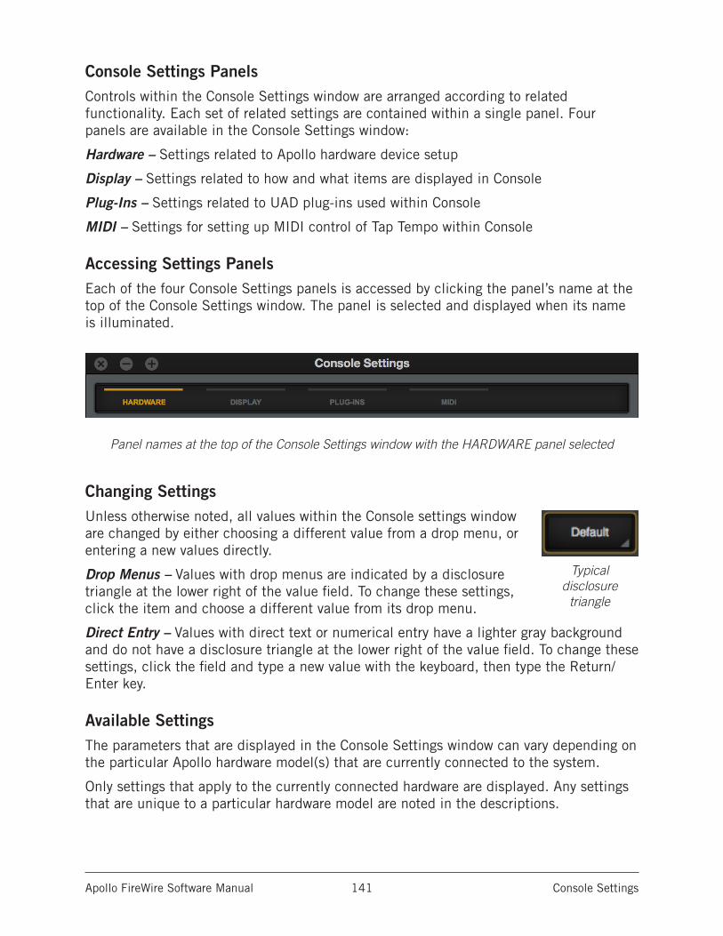
Apollo FireWire Software Manual Console Settings 141
Console Settings PanelsControls within the Console Settings window are arranged according to related functionality. Each set of related settings are contained within a single panel. Four panels are available in the Console Settings window:
Hardware – Settings related to Apollo hardware device setup
Display – Settings related to how and what items are displayed in Console
Plug-Ins – Settings related to UAD plug-ins used within Console
MIDI – Settings for setting up MIDI control of Tap Tempo within Console
Accessing Settings PanelsEach of the four Console Settings panels is accessed by clicking the panel’s name at the top of the Console Settings window. The panel is selected and displayed when its name is illuminated.
Panel names at the top of the Console Settings window with the HARDWARE panel selected
Changing SettingsUnless otherwise noted, all values within the Console settings window are changed by either choosing a different value from a drop menu, or entering a new values directly.
Drop Menus – Values with drop menus are indicated by a disclosure triangle at the lower right of the value field. To change these settings, click the item and choose a different value from its drop menu.
Direct Entry – Values with direct text or numerical entry have a lighter gray background and do not have a disclosure triangle at the lower right of the value field. To change these settings, click the field and type a new value with the keyboard, then type the Return/Enter key.
Available SettingsThe parameters that are displayed in the Console Settings window can vary depending on the particular Apollo hardware model(s) that are currently connected to the system.
Only settings that apply to the currently connected hardware are displayed. Any settings that are unique to a particular hardware model are noted in the descriptions.
Typical disclosure
triangle
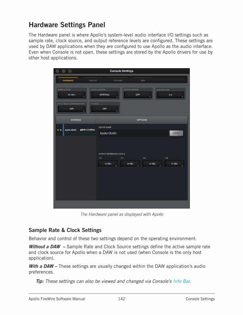
Apollo FireWire Software Manual Console Settings 142
Hardware Settings PanelThe Hardware panel is where Apollo’s system-level audio interface I/O settings such as sample rate, clock source, and output reference levels are configured. These settings are used by DAW applications when they are configured to use Apollo as the audio interface. Even when Console is not open, these settings are stored by the Apollo drivers for use by other host applications.
The Hardware panel as displayed with Apollo
Sample Rate & Clock SettingsBehavior and control of these two settings depend on the operating environment:
Without a DAW – Sample Rate and Clock Source settings define the active sample rate and clock source for Apollo when a DAW is not used (when Console is the only host application).
With a DAW – These settings are usually changed within the DAW application’s audio preferences.
Tip: These settings can also be viewed and changed via Console’s Info Bar.
Apollo FireWire Software Manual Console Settings 143
Sample Rate This setting defines the sample rate that is used for Apollo A/D and D/A conversion and UAD Powered Plug-Ins processing. When using UAD Powered Plug-Ins, higher sample rates require more UAD DSP resources.
Important: When the Clock Source parameter is set to use any external clock source, the sample rate must be manually set to match the sample rate of the external clock.
Clock SourceThis setting determines the master clock source for A/D and D/A conversion. The available values are:
Apollo – Internal clock or external clock from S/PDIF, ADAT, or Word Clock
Apollo 16 – Internal clock or external clock from AES/EBU or Word Clock
If the Clock Source setting is not set to Internal and the external clock signal is not detected, then the text in the Clock Source display is RED (if this occurs, verify connections and external clock device settings).
Note: Only one device in a system can be the master clock. This setting must match the host DAW setting or audio artifacts and/or distortion could occur.
Buffer Size (Windows)
Note: This setting is available on Windows systems only. On Mac systems, the hardware I/O buffer size is set within the DAW application.
This setting determines the hardware I/O buffer size used by a DAW. As values are decreased, DAW throughput latency decreases, but the computer’s CPU load increases. Conversely, as values are increased, DAW throughput latency increases, and the computer’s CPU load is reduced. For related information, see Latency Basics.
Available buffer size values are dependent on the current Sample Rate value. If values in the Buffer Size menu are gray and cannot be selected, change the Sample Rate value.
Note: If audio artifacts occur during DAW playback (clicks, pops, stuttering, etc), the buffer size may need to be increased.
Important: Buffer Size applies to use with a DAW only. It has no effect on Console’s hardware monitoring features or Realtime UAD Processing within Console.
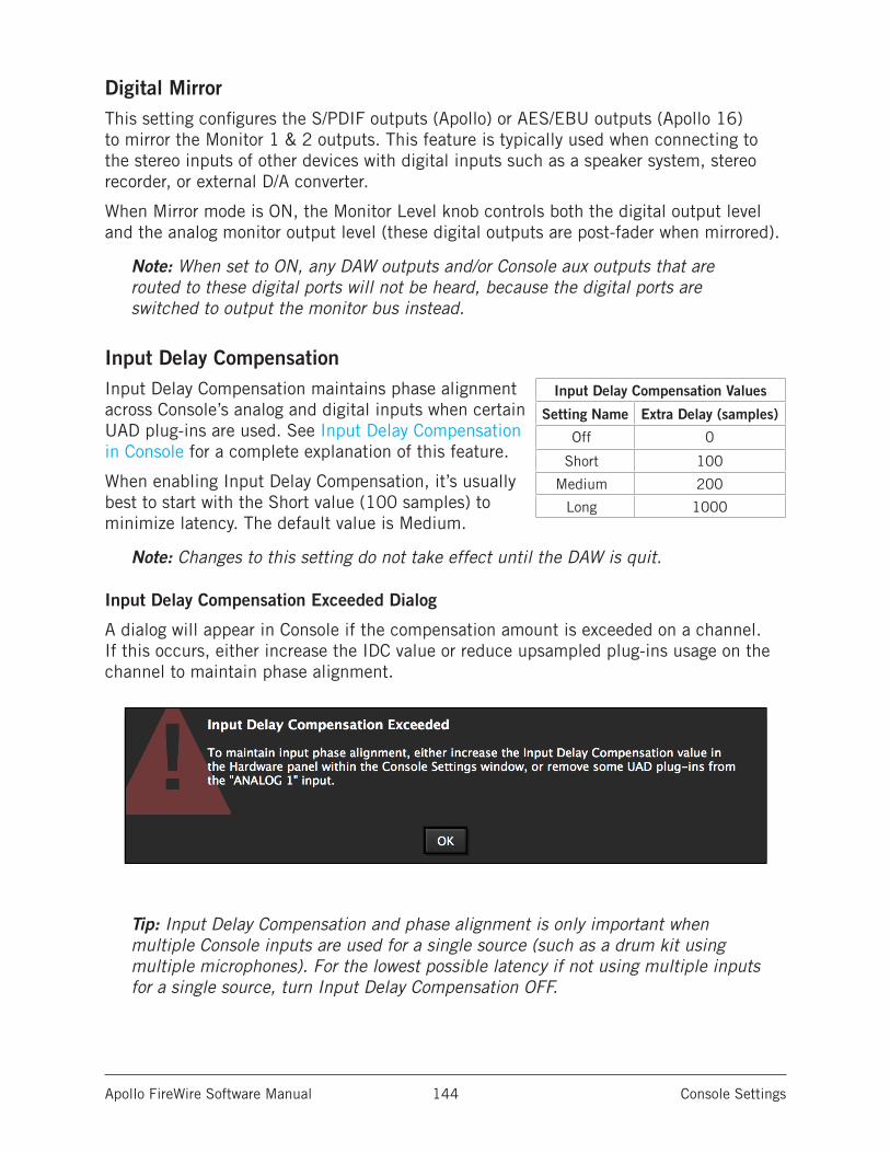
Apollo FireWire Software Manual Console Settings 144
Digital MirrorThis setting configures the S/PDIF outputs (Apollo) or AES/EBU outputs (Apollo 16) to mirror the Monitor 1 & 2 outputs. This feature is typically used when connecting to the stereo inputs of other devices with digital inputs such as a speaker system, stereo recorder, or external D/A converter.
When Mirror mode is ON, the Monitor Level knob controls both the digital output level and the analog monitor output level (these digital outputs are post-fader when mirrored).
Note: When set to ON, any DAW outputs and/or Console aux outputs that are routed to these digital ports will not be heard, because the digital ports are switched to output the monitor bus instead.
Input Delay CompensationInput Delay Compensation maintains phase alignment across Console’s analog and digital inputs when certain UAD plug-ins are used. See Input Delay Compensation in Console for a complete explanation of this feature.
When enabling Input Delay Compensation, it’s usually best to start with the Short value (100 samples) to minimize latency. The default value is Medium.
Note: Changes to this setting do not take effect until the DAW is quit.
Input Delay Compensation Exceeded Dialog
A dialog will appear in Console if the compensation amount is exceeded on a channel. If this occurs, either increase the IDC value or reduce upsampled plug-ins usage on the channel to maintain phase alignment.
Tip: Input Delay Compensation and phase alignment is only important when multiple Console inputs are used for a single source (such as a drum kit using multiple microphones). For the lowest possible latency if not using multiple inputs for a single source, turn Input Delay Compensation OFF.
Input Delay Compensation Values
Setting Name Extra Delay (samples)
Off 0
Short 100
Medium 200
Long 1000
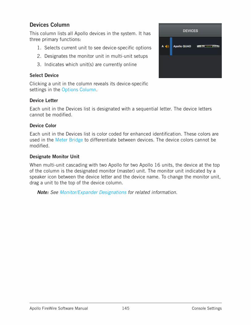
Apollo FireWire Software Manual Console Settings 145
Devices ColumnThis column lists all Apollo devices in the system. It has three primary functions:
1. Selects current unit to see device-specific options
2. Designates the monitor unit in multi-unit setups
3. Indicates which unit(s) are currently online
Select Device
Clicking a unit in the column reveals its device-specific settings in the Options Column.
Device Letter
Each unit in the Devices list is designated with a sequential letter. The device letters cannot be modified.
Device Color
Each unit in the Devices list is color coded for enhanced identification. These colors are used in the Meter Bridge to differentiate between devices. The device colors cannot be modified.
Designate Monitor Unit
When multi-unit cascading with two Apollo for two Apollo 16 units, the device at the top of the column is the designated monitor (master) unit. The monitor unit indicated by a speaker icon between the device letter and the device name. To change the monitor unit, drag a unit to the top of the device column.
Note: See Monitor/Expander Designations for related information.
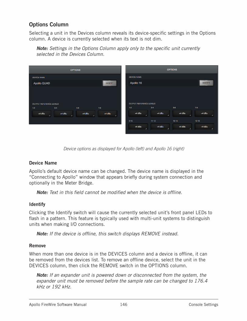
Apollo FireWire Software Manual Console Settings 146
Options ColumnSelecting a unit in the Devices column reveals its device-specific settings in the Options column. A device is currently selected when its text is not dim.
Note: Settings in the Options Column apply only to the specific unit currently selected in the Devices Column.
Device options as displayed for Apollo (left) and Apollo 16 (right)
Device Name
Apollo’s default device name can be changed. The device name is displayed in the “Connecting to Apollo” window that appears briefly during system connection and optionally in the Meter Bridge.
Note: Text in this field cannot be modified when the device is offline.
Identify
Clicking the Identify switch will cause the currently selected unit’s front panel LEDs to flash in a pattern. This feature is typically used with multi-unit systems to distinguish units when making I/O connections.
Note: If the device is offline, this switch displays REMOVE instead.
Remove
When more than one device is in the DEVICES column and a device is offline, it can be removed from the devices list. To remove an offline device, select the unit in the DEVICES column, then click the REMOVE switch in the OPTIONS column.
Note: If an expander unit is powered down or disconnected from the system, the expander unit must be removed before the sample rate can be changed to 176.4 kHz or 192 kHz.
Apollo FireWire Software Manual Console Settings 147
Output Reference Levels
These drop menus set the reference level for the line outputs. The number of menus displayed depends on the currently connected Apollo hardware (for example, Apollo 16, which features more outputs, will display more output menus).
The line output reference levels can be set to –10 dBV or +4 dBu in adjacent pairs. The value is usually set to match the nominal input level of devices connected to these outputs (a setting of +4 dBu outputs a higher signal level than –10 dBV).
Note: Input reference levels for the analog line inputs are set in Console’s channel input strips.
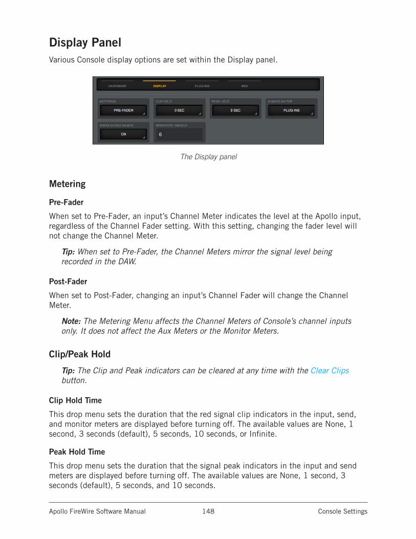
Apollo FireWire Software Manual Console Settings 148
Display PanelVarious Console display options are set within the Display panel.
The Display panel
Metering
Pre-Fader
When set to Pre-Fader, an input’s Channel Meter indicates the level at the Apollo input, regardless of the Channel Fader setting. With this setting, changing the fader level will not change the Channel Meter.
Tip: When set to Pre-Fader, the Channel Meters mirror the signal level being recorded in the DAW.
Post-Fader
When set to Post-Fader, changing an input’s Channel Fader will change the Channel Meter.
Note: The Metering Menu affects the Channel Meters of Console’s channel inputs only. It does not affect the Aux Meters or the Monitor Meters.
Clip/Peak Hold
Tip: The Clip and Peak indicators can be cleared at any time with the Clear Clips button.
Clip Hold Time
This drop menu sets the duration that the red signal clip indicators in the input, send, and monitor meters are displayed before turning off. The available values are None, 1 second, 3 seconds (default), 5 seconds, 10 seconds, or Infinite.
Peak Hold Time
This drop menu sets the duration that the signal peak indicators in the input and send meters are displayed before turning off. The available values are None, 1 second, 3 seconds (default), 5 seconds, and 10 seconds.
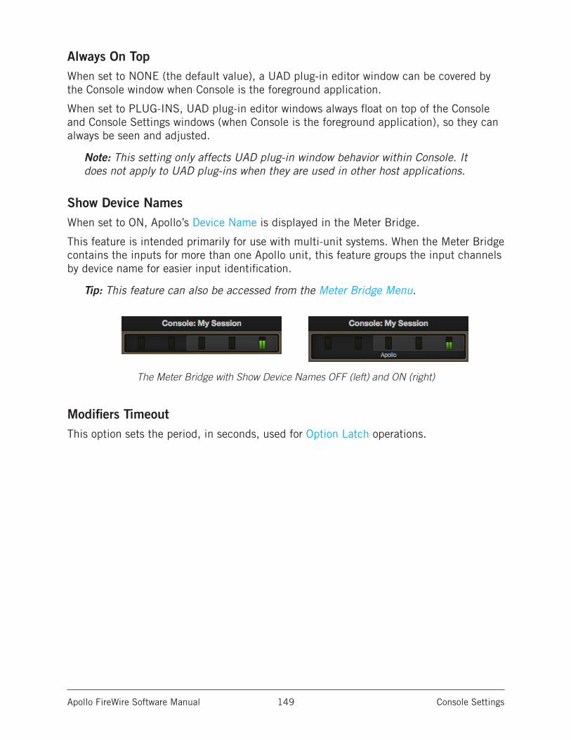
Apollo FireWire Software Manual Console Settings 149
Always On TopWhen set to NONE (the default value), a UAD plug-in editor window can be covered by the Console window when Console is the foreground application.
When set to PLUG-INS, UAD plug-in editor windows always float on top of the Console and Console Settings windows (when Console is the foreground application), so they can always be seen and adjusted.
Note: This setting only affects UAD plug-in window behavior within Console. It does not apply to UAD plug-ins when they are used in other host applications.
Show Device NamesWhen set to ON, Apollo’s Device Name is displayed in the Meter Bridge.
This feature is intended primarily for use with multi-unit systems. When the Meter Bridge contains the inputs for more than one Apollo unit, this feature groups the input channels by device name for easier input identification.
Tip: This feature can also be accessed from the Meter Bridge Menu.
The Meter Bridge with Show Device Names OFF (left) and ON (right)
Modifiers TimeoutThis option sets the period, in seconds, used for Option Latch operations.
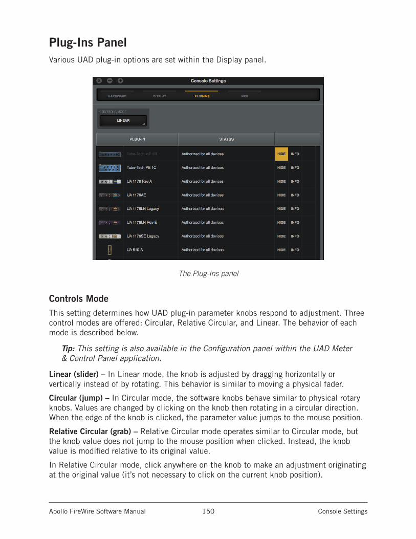
Apollo FireWire Software Manual Console Settings 150
Plug-Ins PanelVarious UAD plug-in options are set within the Display panel.
The Plug-Ins panel
Controls ModeThis setting determines how UAD plug-in parameter knobs respond to adjustment. Three control modes are offered: Circular, Relative Circular, and Linear. The behavior of each mode is described below.
Tip: This setting is also available in the Configuration panel within the UAD Meter & Control Panel application.
Linear (slider) – In Linear mode, the knob is adjusted by dragging horizontally or vertically instead of by rotating. This behavior is similar to moving a physical fader.
Circular (jump) – In Circular mode, the software knobs behave similar to physical rotary knobs. Values are changed by clicking on the knob then rotating in a circular direction. When the edge of the knob is clicked, the parameter value jumps to the mouse position.
Relative Circular (grab) – Relative Circular mode operates similar to Circular mode, but the knob value does not jump to the mouse position when clicked. Instead, the knob value is modified relative to its original value.
In Relative Circular mode, click anywhere on the knob to make an adjustment originating at the original value (it’s not necessary to click on the current knob position).
Apollo FireWire Software Manual Console Settings 151
Tip: To increase resolution when in adjusting rotary controls in circular and relative circular modes, increase the radius of the mouse relative to the knob while dragging (move the mouse farther away from the knob while dragging in a circular motion).
Plug-In ColumnAll installed UAD plug-ins are displayed in the list in alphabetical order. Settings for each UAD plug-in are contained within its row. Vertically scroll the list to see plug-ins that are not currently in view.
Status ColumnThe authorization status and/or demo state of the plug-in is displayed here. The info shown mirrors the status shown in the Plug-Ins panel within the UAD Meter & Control Panel application.
Tip: To start a plug-in demo, click START DEMO in the Plug-Ins panel within the UAD Meter & Control Panel application, or in the UAD Toolbar at the bottom of each UAD plug-in editor.
Hide ColumnThese switches prevent UAD plug-ins from being visible from within Console. Click a plug-in’s HIDE switch to toggle the state. The plug-in is hidden when HIDE is yellow and its title and icon are dim.
This function is used to restrict the availability of assignable plug-ins in plug-in lists. By default, all plug-ins are visible, even if they are unlicensed or the demo period is expired. By hiding plug-ins that are unlicensed or expired, only plug-ins that can process audio are exposed, which can be convenient for more rapid assignments.
Info ColumnThese switches open the plug-in’s product pages at uaudio.com in the default web browser, providing a general overview the plug-in.
Tip: For detailed operating instructions for each UAD plug-in, see the UAD Plug-Ins Manual.
Buy ColumnAdds an unlicensed plug-in to the shopping cart at the UA online store. Confirm you are logged in to the desired account at uaudio.com when purchasing the plug-in.
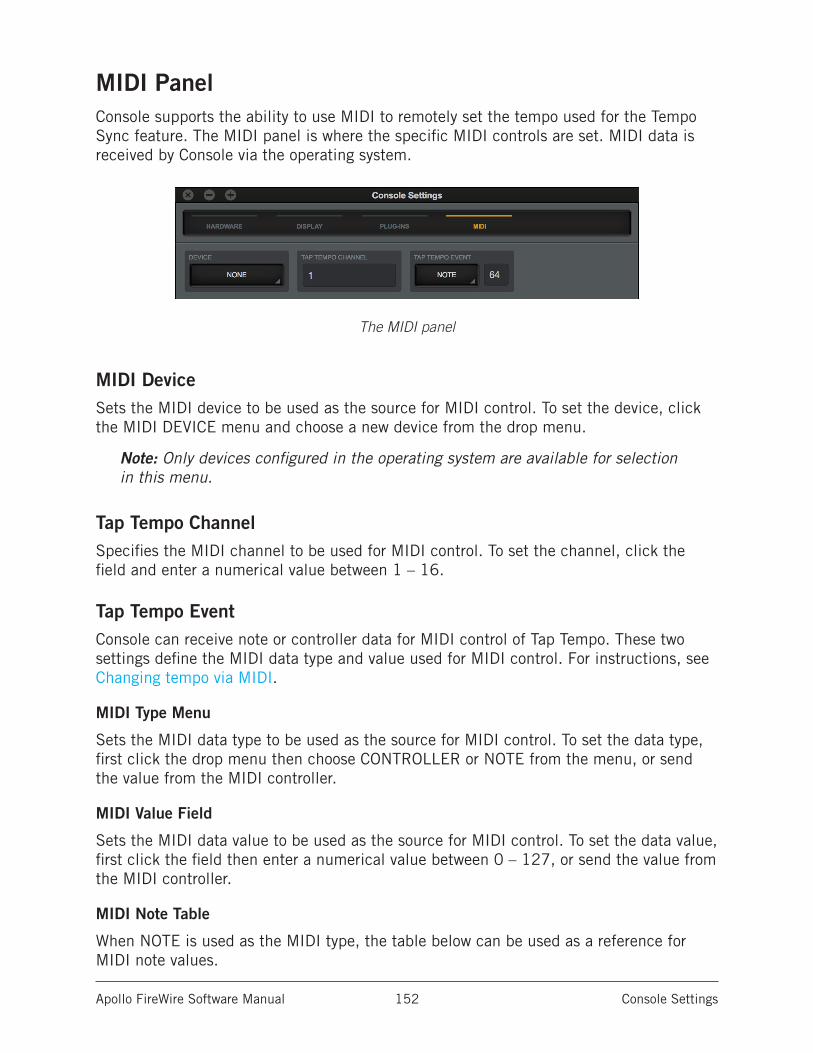
Apollo FireWire Software Manual Console Settings 152
MIDI PanelConsole supports the ability to use MIDI to remotely set the tempo used for the Tempo Sync feature. The MIDI panel is where the specific MIDI controls are set. MIDI data is received by Console via the operating system.
The MIDI panel
MIDI DeviceSets the MIDI device to be used as the source for MIDI control. To set the device, click the MIDI DEVICE menu and choose a new device from the drop menu.
Note: Only devices configured in the operating system are available for selection in this menu.
Tap Tempo ChannelSpecifies the MIDI channel to be used for MIDI control. To set the channel, click the field and enter a numerical value between 1 – 16.
Tap Tempo EventConsole can receive note or controller data for MIDI control of Tap Tempo. These two settings define the MIDI data type and value used for MIDI control. For instructions, see Changing tempo via MIDI.
MIDI Type Menu
Sets the MIDI data type to be used as the source for MIDI control. To set the data type, first click the drop menu then choose CONTROLLER or NOTE from the menu, or send the value from the MIDI controller.
MIDI Value Field
Sets the MIDI data value to be used as the source for MIDI control. To set the data value, first click the field then enter a numerical value between 0 – 127, or send the value from the MIDI controller.
MIDI Note Table
When NOTE is used as the MIDI type, the table below can be used as a reference for MIDI note values.
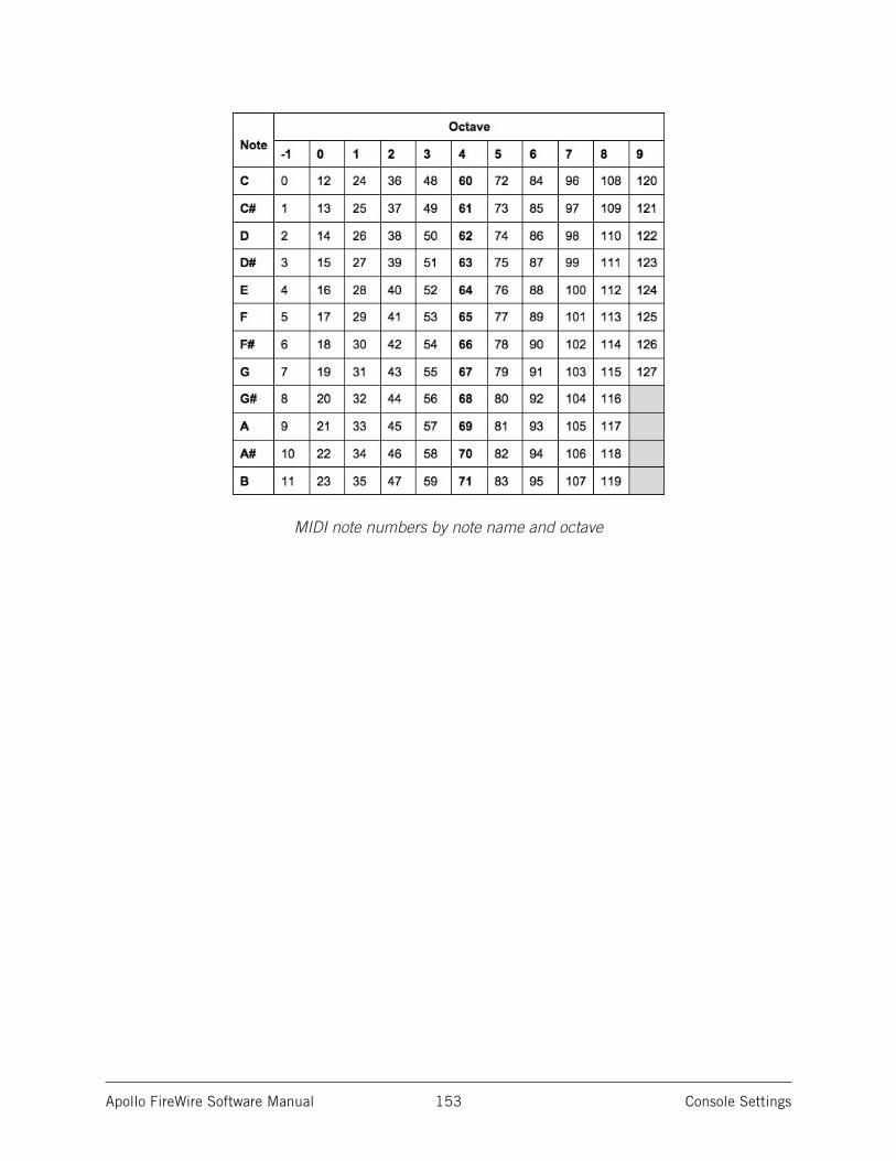
Apollo FireWire Software Manual Console Settings 153
MIDI note numbers by note name and octave
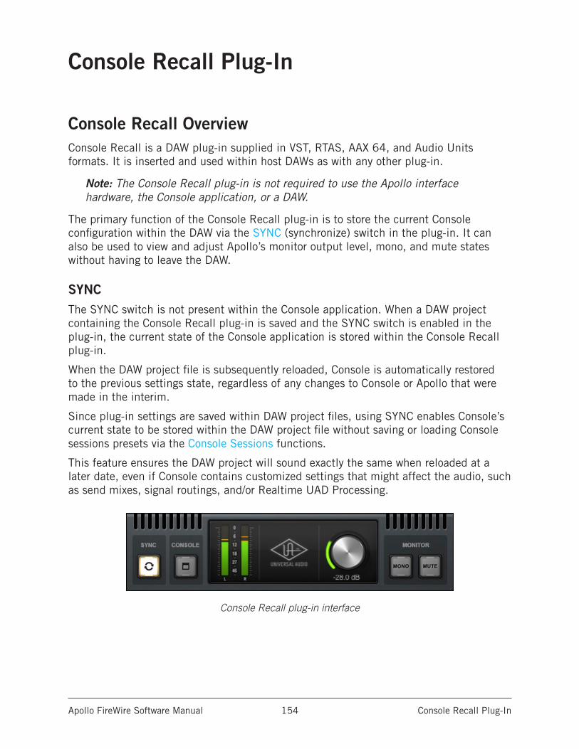
Apollo FireWire Software Manual Console Recall Plug-In 154
Console Recall Plug-In
Console Recall OverviewConsole Recall is a DAW plug-in supplied in VST, RTAS, AAX 64, and Audio Units formats. It is inserted and used within host DAWs as with any other plug-in.
Note: The Console Recall plug-in is not required to use the Apollo interface hardware, the Console application, or a DAW.
The primary function of the Console Recall plug-in is to store the current Console configuration within the DAW via the SYNC (synchronize) switch in the plug-in. It can also be used to view and adjust Apollo’s monitor output level, mono, and mute states without having to leave the DAW.
SYNCThe SYNC switch is not present within the Console application. When a DAW project containing the Console Recall plug-in is saved and the SYNC switch is enabled in the plug-in, the current state of the Console application is stored within the Console Recall plug-in.
When the DAW project file is subsequently reloaded, Console is automatically restored to the previous settings state, regardless of any changes to Console or Apollo that were made in the interim.
Since plug-in settings are saved within DAW project files, using SYNC enables Console’s current state to be stored within the DAW project file without saving or loading Console sessions presets via the Console Sessions functions.
This feature ensures the DAW project will sound exactly the same when reloaded at a later date, even if Console contains customized settings that might affect the audio, such as send mixes, signal routings, and/or Realtime UAD Processing.
Console Recall plug-in interface
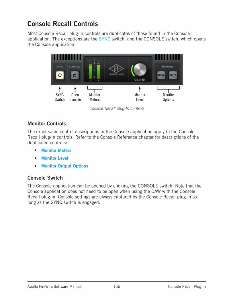
Apollo FireWire Software Manual Console Recall Plug-In 155
Console Recall ControlsMost Console Recall plug-in controls are duplicates of those found in the Console application. The exceptions are the SYNC switch, and the CONSOLE switch, which opens the Console application.
Console Recall plug-In controls
Monitor ControlsThe exact same control descriptions in the Console application apply to the Console Recall plug-in controls. Refer to the Console Reference chapter for descriptions of the duplicated controls:
• Monitor Meters
• Monitor Level
• Monitor Output Options
Console SwitchThe Console application can be opened by clicking the CONSOLE switch. Note that the Console application does not need to be open when using the DAW with the Console Recall plug-in; Console settings are always captured by the Console Recall plug-in as long as the SYNC switch is engaged.
SYNCSwitch
MonitorMeters
Monitor Level
Monitor Options
OpenConsole
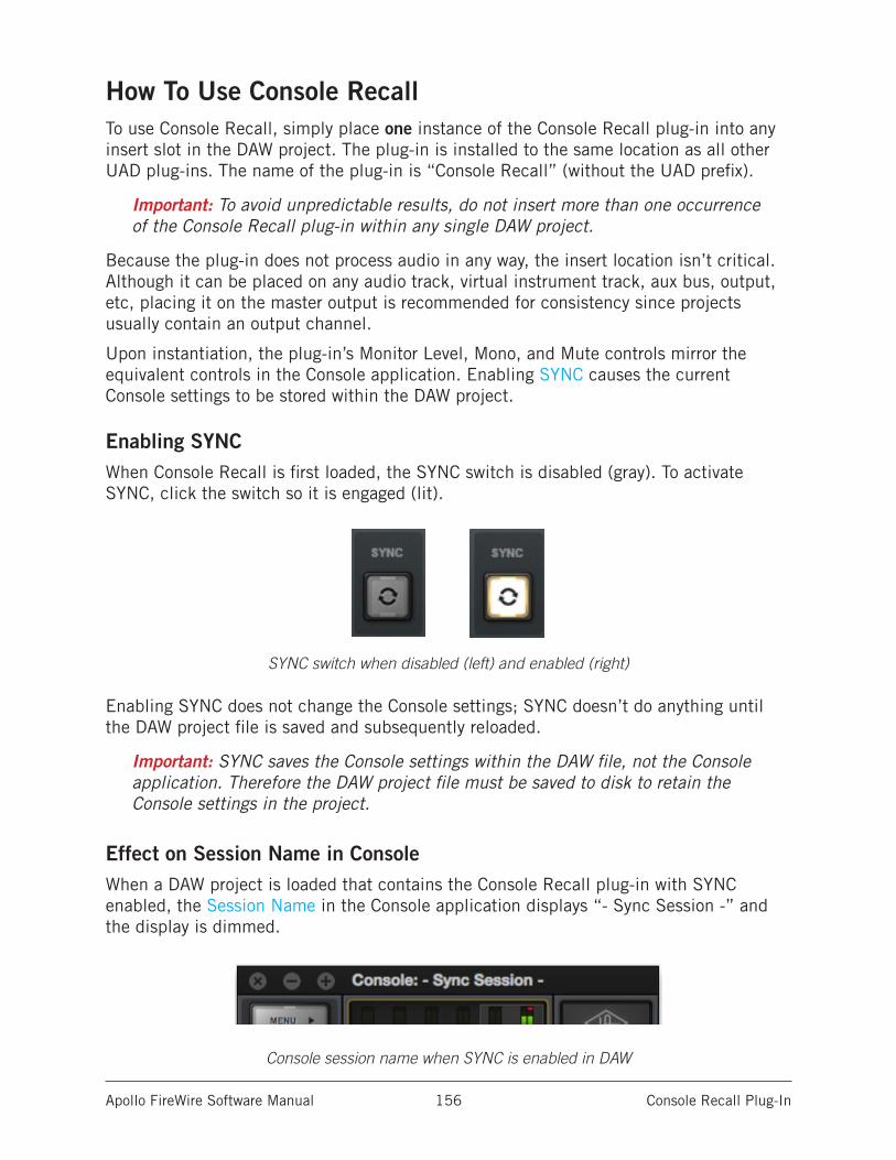
Apollo FireWire Software Manual Console Recall Plug-In 156
How To Use Console RecallTo use Console Recall, simply place one instance of the Console Recall plug-in into any insert slot in the DAW project. The plug-in is installed to the same location as all other UAD plug-ins. The name of the plug-in is “Console Recall” (without the UAD prefix).
Important: To avoid unpredictable results, do not insert more than one occurrence of the Console Recall plug-in within any single DAW project.
Because the plug-in does not process audio in any way, the insert location isn’t critical. Although it can be placed on any audio track, virtual instrument track, aux bus, output, etc, placing it on the master output is recommended for consistency since projects usually contain an output channel.
Upon instantiation, the plug-in’s Monitor Level, Mono, and Mute controls mirror the equivalent controls in the Console application. Enabling SYNC causes the current Console settings to be stored within the DAW project.
Enabling SYNCWhen Console Recall is first loaded, the SYNC switch is disabled (gray). To activate SYNC, click the switch so it is engaged (lit).
SYNC switch when disabled (left) and enabled (right)
Enabling SYNC does not change the Console settings; SYNC doesn’t do anything until the DAW project file is saved and subsequently reloaded.
Important: SYNC saves the Console settings within the DAW file, not the Console application. Therefore the DAW project file must be saved to disk to retain the Console settings in the project.
Effect on Session Name in ConsoleWhen a DAW project is loaded that contains the Console Recall plug-in with SYNC enabled, the Session Name in the Console application displays “- Sync Session -” and the display is dimmed.
Console session name when SYNC is enabled in DAW
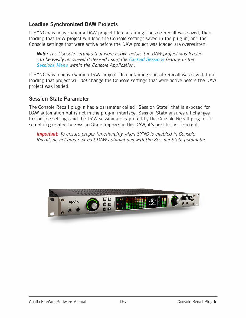
Apollo FireWire Software Manual Console Recall Plug-In 157
Loading Synchronized DAW ProjectsIf SYNC was active when a DAW project file containing Console Recall was saved, then loading that DAW project will load the Console settings saved in the plug-in, and the Console settings that were active before the DAW project was loaded are overwritten.
Note: The Console settings that were active before the DAW project was loaded can be easily recovered if desired using the Cached Sessions feature in the Sessions Menu within the Console Application.
If SYNC was inactive when a DAW project file containing Console Recall was saved, then loading that project will not change the Console settings that were active before the DAW project was loaded.
Session State ParameterThe Console Recall plug-in has a parameter called “Session State” that is exposed for DAW automation but is not in the plug-in interface. Session State ensures all changes to Console settings and the DAW session are captured by the Console Recall plug-in. If something related to Session State appears in the DAW, it’s best to just ignore it.
Important: To ensure proper functionality when SYNC is enabled in Console Recall, do not create or edit DAW automations with the Session State parameter.
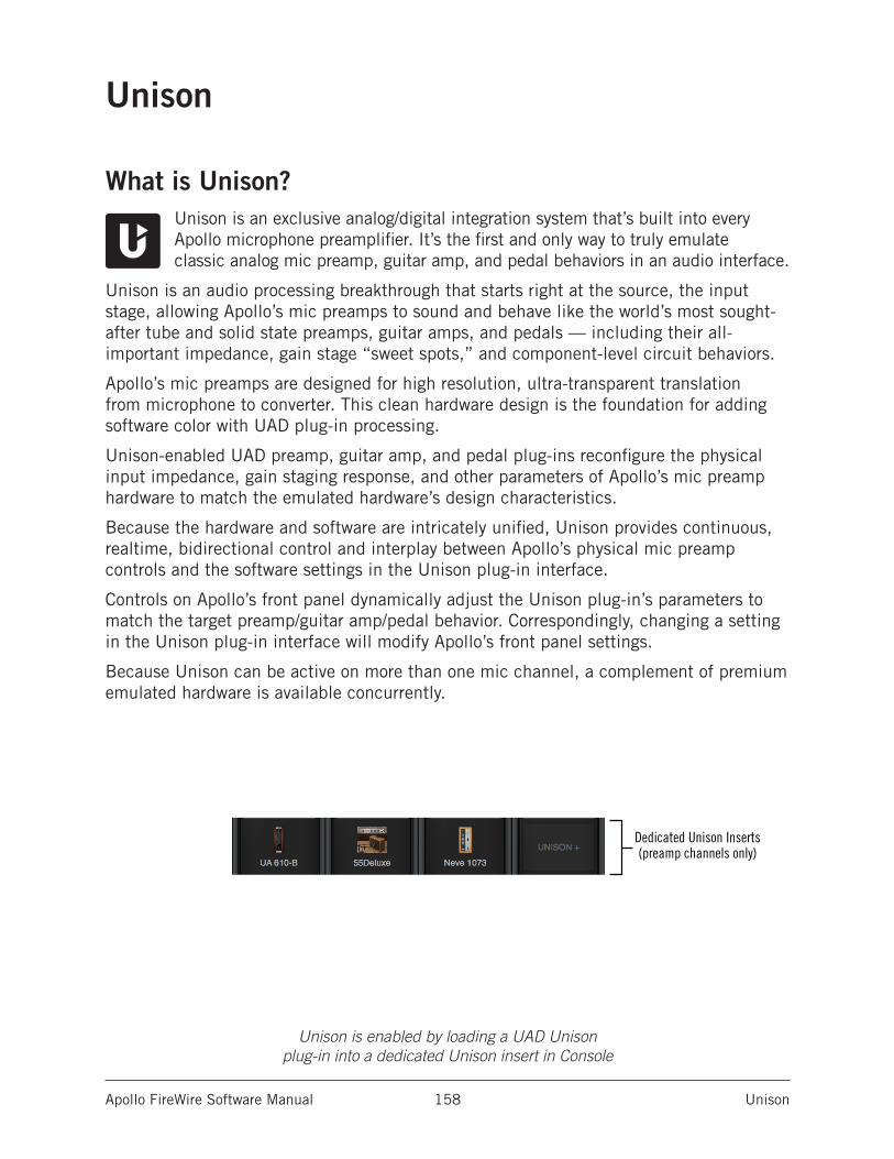
Apollo FireWire Software Manual Unison 158
Unison
What is Unison?Unison is an exclusive analog/digital integration system that’s built into every Apollo microphone preamplifier. It’s the first and only way to truly emulate classic analog mic preamp, guitar amp, and pedal behaviors in an audio interface.
Unison is an audio processing breakthrough that starts right at the source, the input stage, allowing Apollo’s mic preamps to sound and behave like the world’s most sought-after tube and solid state preamps, guitar amps, and pedals — including their all-important impedance, gain stage “sweet spots,” and component-level circuit behaviors.
Apollo’s mic preamps are designed for high resolution, ultra-transparent translation from microphone to converter. This clean hardware design is the foundation for adding software color with UAD plug-in processing.
Unison-enabled UAD preamp, guitar amp, and pedal plug-ins reconfigure the physical input impedance, gain staging response, and other parameters of Apollo’s mic preamp hardware to match the emulated hardware’s design characteristics.
Because the hardware and software are intricately unified, Unison provides continuous, realtime, bidirectional control and interplay between Apollo’s physical mic preamp controls and the software settings in the Unison plug-in interface.
Controls on Apollo’s front panel dynamically adjust the Unison plug-in’s parameters to match the target preamp/guitar amp/pedal behavior. Correspondingly, changing a setting in the Unison plug-in interface will modify Apollo’s front panel settings.
Because Unison can be active on more than one mic channel, a complement of premium emulated hardware is available concurrently.
Unison is enabled by loading a UAD Unison plug-in into a dedicated Unison insert in Console
Dedicated Unison Inserts(preamp channels only)
Apollo FireWire Software Manual Unison 159
Unison FeaturesUnison technology enables these Apollo features, all with Realtime UAD Processing:
• Alternate microphone preamplifier sound – Apollo’s ultra-transparent mic preamps inherit all the unique sonic and input characteristics of the emulated hardware preamp, guitar amp, or pedal, including the mic, line, and Hi-Z inputs.
• Realistic tandem control – Unison facilitates seamless interactive control of Unison preamp plug-in settings using Apollo’s digitally-controlled hardware and/or the plug-in interface. All equivalent preamp controls (gain, pad, polarity, etc) are mirrored and bidirectional. The preamp controls respond to adjustments with precisely the same interplay behavior as the emulated hardware, including gain levels and clipping points.
• Hardware input impedance – All Apollo mic preamps feature variable input impedance in analog hardware that can be physically switched by Unison plug-ins for physical, microphone-to-preamp resistive interaction. This impedance switching enables Apollo’s preamps to physically match the emulated unit’s input impedance, which can significantly impact the sound of a microphone. Because the electrical loading occurs on input, prior to A/D conversion, the realism is faithful to the original target hardware preamp.
• Tactile gain staging – Apollo’s front panel preamp knob can independently adjust all gain and level parameters available within the Unison plug-in via Gain Stage Mode. The gain stage being adjusted can be remotely switched via Apollo, so multiple gain levels and their associated colorations can be tuned from the hardware knob for precise physical tactile control, all without using the Unison plug-in’s software interface.
Unison Plug-InsNote: In all descriptive text, “Unison plug-in” is defined as any Unison-enabled UAD mic preamp plug-in, UAD guitar & bass amp plug-in, or UAD pedal plug-in.
Unison-enabled UAD plug-ins are uniquely coded for Unison integration. Only UAD plug-ins that are Unison-enabled can be loaded in Console’s Unison Insert Location.
For a complete list of all Unison-enabled UAD plug-ins, see “Unison Plug-Ins List” in the appendix at the back of the UAD Plug-Ins Manual.
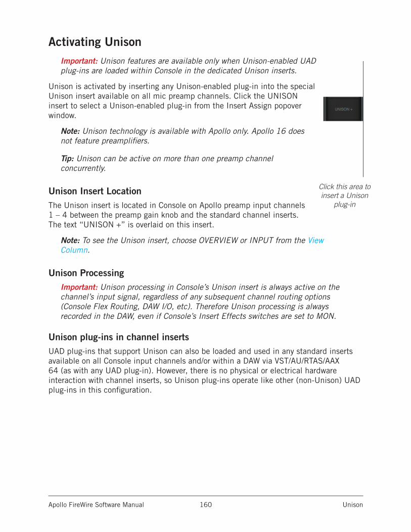
Apollo FireWire Software Manual Unison 160
Activating UnisonImportant: Unison features are available only when Unison-enabled UAD plug-ins are loaded within Console in the dedicated Unison inserts.
Unison is activated by inserting any Unison-enabled plug-in into the special Unison insert available on all mic preamp channels. Click the UNISON insert to select a Unison-enabled plug-in from the Insert Assign popover window.
Note: Unison technology is available with Apollo only. Apollo 16 does not feature preamplifiers.
Tip: Unison can be active on more than one preamp channel concurrently.
Unison Insert LocationThe Unison insert is located in Console on Apollo preamp input channels 1 – 4 between the preamp gain knob and the standard channel inserts. The text “UNISON +” is overlaid on this insert.
Note: To see the Unison insert, choose OVERVIEW or INPUT from the View Column.
Unison ProcessingImportant: Unison processing in Console’s Unison insert is always active on the channel’s input signal, regardless of any subsequent channel routing options (Console Flex Routing, DAW I/O, etc). Therefore Unison processing is always recorded in the DAW, even if Console’s Insert Effects switches are set to MON.
Unison plug-ins in channel insertsUAD plug-ins that support Unison can also be loaded and used in any standard inserts available on all Console input channels and/or within a DAW via VST/AU/RTAS/AAX 64 (as with any UAD plug-in). However, there is no physical or electrical hardware interaction with channel inserts, so Unison plug-ins operate like other (non-Unison) UAD plug-ins in this configuration.
Dedicated Unison Inserts(preamp channels only)
Click this area to insert a Unison
plug-in
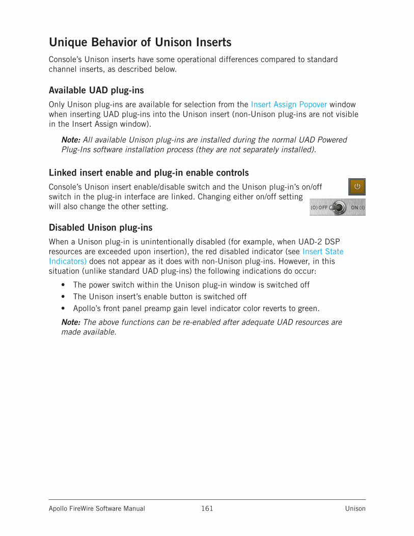
Apollo FireWire Software Manual Unison 161
Unique Behavior of Unison InsertsConsole’s Unison inserts have some operational differences compared to standard channel inserts, as described below.
Available UAD plug-insOnly Unison plug-ins are available for selection from the Insert Assign Popover window when inserting UAD plug-ins into the Unison insert (non-Unison plug-ins are not visible in the Insert Assign window).
Note: All available Unison plug-ins are installed during the normal UAD Powered Plug-Ins software installation process (they are not separately installed).
Linked insert enable and plug-in enable controlsConsole’s Unison insert enable/disable switch and the Unison plug-in’s on/off switch in the plug-in interface are linked. Changing either on/off setting will also change the other setting.
Disabled Unison plug-insWhen a Unison plug-in is unintentionally disabled (for example, when UAD-2 DSP resources are exceeded upon insertion), the red disabled indicator (see Insert State Indicators) does not appear as it does with non-Unison plug-ins. However, in this situation (unlike standard UAD plug-ins) the following indications do occur:
• The power switch within the Unison plug-in window is switched off• The Unison insert’s enable button is switched off• Apollo’s front panel preamp gain level indicator color reverts to green.
Note: The above functions can be re-enabled after adequate UAD resources are made available.
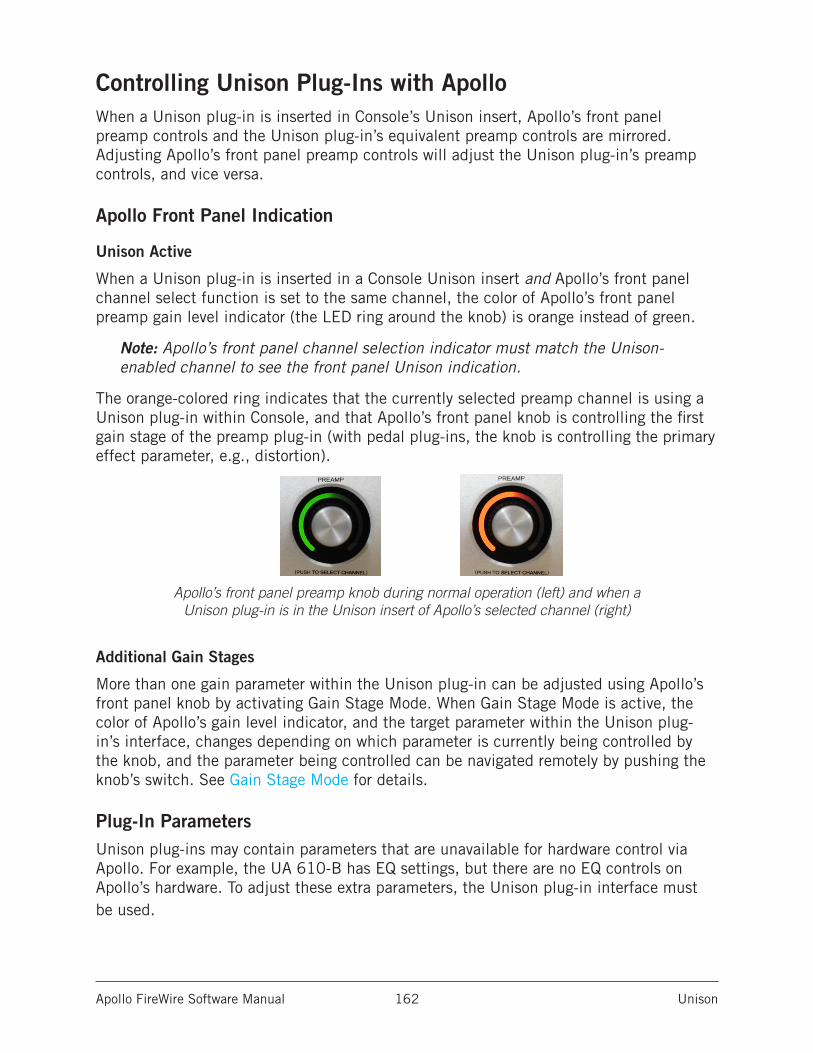
Apollo FireWire Software Manual Unison 162
Controlling Unison Plug-Ins with ApolloWhen a Unison plug-in is inserted in Console’s Unison insert, Apollo’s front panel preamp controls and the Unison plug-in’s equivalent preamp controls are mirrored. Adjusting Apollo’s front panel preamp controls will adjust the Unison plug-in’s preamp controls, and vice versa.
Apollo Front Panel Indication
Unison Active
When a Unison plug-in is inserted in a Console Unison insert and Apollo’s front panel channel select function is set to the same channel, the color of Apollo’s front panel preamp gain level indicator (the LED ring around the knob) is orange instead of green.
Note: Apollo’s front panel channel selection indicator must match the Unison-enabled channel to see the front panel Unison indication.
The orange-colored ring indicates that the currently selected preamp channel is using a Unison plug-in within Console, and that Apollo’s front panel knob is controlling the first gain stage of the preamp plug-in (with pedal plug-ins, the knob is controlling the primary effect parameter, e.g., distortion).
Apollo’s front panel preamp knob during normal operation (left) and when a Unison plug-in is in the Unison insert of Apollo’s selected channel (right)
Additional Gain Stages
More than one gain parameter within the Unison plug-in can be adjusted using Apollo’s front panel knob by activating Gain Stage Mode. When Gain Stage Mode is active, the color of Apollo’s gain level indicator, and the target parameter within the Unison plug-in’s interface, changes depending on which parameter is currently being controlled by the knob, and the parameter being controlled can be navigated remotely by pushing the knob’s switch. See Gain Stage Mode for details.
Plug-In ParametersUnison plug-ins may contain parameters that are unavailable for hardware control via Apollo. For example, the UA 610-B has EQ settings, but there are no EQ controls on Apollo’s hardware. To adjust these extra parameters, the Unison plug-in interface must be used.
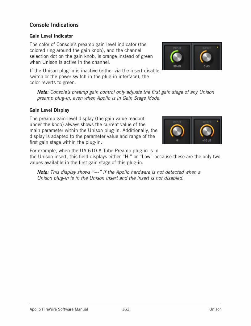
Apollo FireWire Software Manual Unison 163
Console Indications
Gain Level Indicator
The color of Console’s preamp gain level indicator (the colored ring around the gain knob), and the channel selection dot on the gain knob, is orange instead of green when Unison is active in the channel.
If the Unison plug-in is inactive (either via the insert disable switch or the power switch in the plug-in interface), the color reverts to green.
Note: Console’s preamp gain control only adjusts the first gain stage of any Unison preamp plug-in, even when Apollo is in Gain Stage Mode.
Gain Level Display
The preamp gain level display (the gain value readout under the knob) always shows the current value of the main parameter within the Unison plug-in. Additionally, the display is adapted to the parameter value and range of the first gain stage within the plug-in.
For example, when the UA 610-A Tube Preamp plug-in is in the Unison insert, this field displays either “Hi” or “Low” because these are the only two values available in the first gain stage of this plug-in.
Note: This display shows “---” if the Apollo hardware is not detected when a Unison plug-in is in the Unison insert and the insert is not disabled.
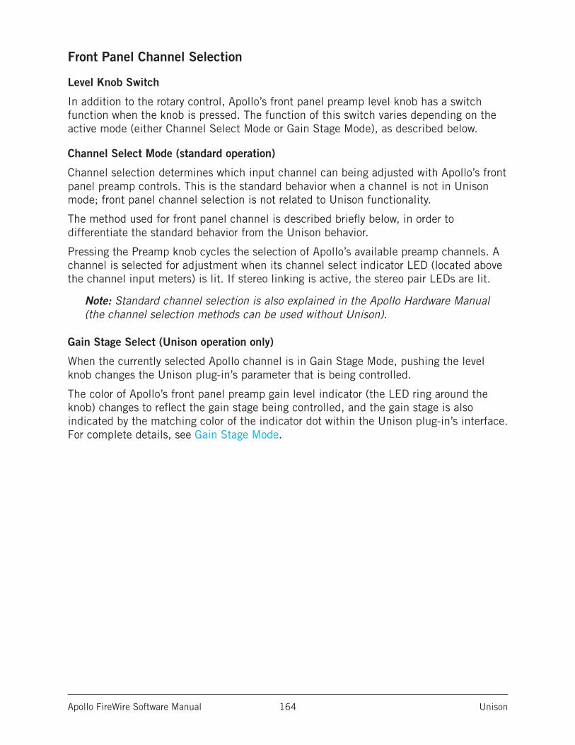
Apollo FireWire Software Manual Unison 164
Front Panel Channel Selection
Level Knob Switch
In addition to the rotary control, Apollo’s front panel preamp level knob has a switch function when the knob is pressed. The function of this switch varies depending on the active mode (either Channel Select Mode or Gain Stage Mode), as described below.
Channel Select Mode (standard operation)
Channel selection determines which input channel can being adjusted with Apollo’s front panel preamp controls. This is the standard behavior when a channel is not in Unison mode; front panel channel selection is not related to Unison functionality.
The method used for front panel channel is described briefly below, in order to differentiate the standard behavior from the Unison behavior.
Pressing the Preamp knob cycles the selection of Apollo’s available preamp channels. A channel is selected for adjustment when its channel select indicator LED (located above the channel input meters) is lit. If stereo linking is active, the stereo pair LEDs are lit.
Note: Standard channel selection is also explained in the Apollo Hardware Manual (the channel selection methods can be used without Unison).
Gain Stage Select (Unison operation only)
When the currently selected Apollo channel is in Gain Stage Mode, pushing the level knob changes the Unison plug-in’s parameter that is being controlled.
The color of Apollo’s front panel preamp gain level indicator (the LED ring around the knob) changes to reflect the gain stage being controlled, and the gain stage is also indicated by the matching color of the indicator dot within the Unison plug-in’s interface. For complete details, see Gain Stage Mode.
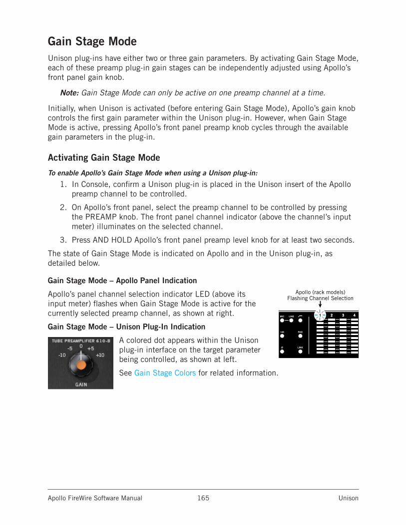
Apollo FireWire Software Manual Unison 165
Gain Stage ModeUnison plug-ins have either two or three gain parameters. By activating Gain Stage Mode, each of these preamp plug-in gain stages can be independently adjusted using Apollo’s front panel gain knob.
Note: Gain Stage Mode can only be active on one preamp channel at a time.
Initially, when Unison is activated (before entering Gain Stage Mode), Apollo’s gain knob controls the first gain parameter within the Unison plug-in. However, when Gain Stage Mode is active, pressing Apollo’s front panel preamp knob cycles through the available gain parameters in the plug-in.
Activating Gain Stage Mode
To enable Apollo’s Gain Stage Mode when using a Unison plug-in:
1. In Console, confirm a Unison plug-in is placed in the Unison insert of the Apollo preamp channel to be controlled.
2. On Apollo’s front panel, select the preamp channel to be controlled by pressing the PREAMP knob. The front panel channel indicator (above the channel’s input meter) illuminates on the selected channel.
3. Press AND HOLD Apollo’s front panel preamp level knob for at least two seconds.
The state of Gain Stage Mode is indicated on Apollo and in the Unison plug-in, as detailed below.
Gain Stage Mode – Apollo Panel Indication
Apollo’s panel channel selection indicator LED (above its input meter) flashes when Gain Stage Mode is active for the currently selected preamp channel, as shown at right.
Gain Stage Mode – Unison Plug-In Indication
A colored dot appears within the Unison plug-in interface on the target parameter being controlled, as shown at left.
See Gain Stage Colors for related information.
INTCLOCKMIC
+48
Ø LINK
1 2 1 23 4 5 6 7 8
PAD
LINE
EXTCLOCK
UADLINK
PAD
MIC/LINE
+48V
Ø LINK
CLIP
0
-6-3
-9-12-15-18-21-27
CLIP
0
-6-3
-9-12-15-18-21-27
Apollo TwinFlashing Channel Selection
Apollo (rack models)Flashing Channel Selection
2 3 41
Apollo FireWire Software Manual Unison 166
Deactivating Gain Stage Mode
Gain Stage Mode can be deactivated with any of these methods:
• Press and hold Apollo’s front panel gain level knob for at least two seconds• Disable the Unison plug-in via the plug-in editor window within Console• Disable the Unison plug-in via the on/off parameter within the plug-in interface• Remove the Unison plug-in from Console’s Unison insert
When Gain Stage Mode is deactivated, the following changes occur:
1. The gain stage select function (pushing the gain level knob) reverts to the channel select function
2. The channel selection indicator on Apollo’s front panel stops flashing
3. If a gain stage other than the first gain stage was being controlled, Apollo’s gain level knob reverts to control of the first gain stage of the Unison plug-in, and the level indicator color reverts to orange.
Controlling Individual Gain Stages
Selecting Gain Parameters For Control
When the currently selected Unison plug-in channel is in Gain Stage Mode (when its channel selection indicator is flashing), push Apollo’s gain level knob to cycle through the available gain parameters within the Unison plug-in.
Note: Unlike Apollo’s front panel knob, Console’s preamp gain control only adjusts the first gain stage of any Unison plug-in when Apollo is in Gain Stage Mode. To adjust other gain stages from within Console, use Apollo’s gain knob or the Unison plug-in interface.
Gain Stage Colors
The gain stage being controlled is indicated by unique, matching indicator colors on Apollo’s front panel and within the Unison plug-in’s interface.
The color of the gain level indicator on Apollo’s front panel (the LED ring around the knob) changes with each gain stage, and the matching color dot within the Unison plug-in’s interface moves to the target gain parameter being controlled.
The gain stages available for control, and their associated colors, are:
• Orange – Gain stage one; the Gain parameter• Amber – Gain stage two; the Level parameter• Green – Gain stage three, the clean (non-modeled) output control
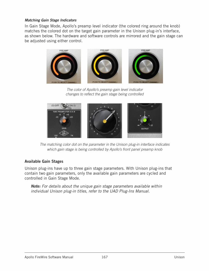
Apollo FireWire Software Manual Unison 167
Matching Gain Stage Indicators
In Gain Stage Mode, Apollo’s preamp level indicator (the colored ring around the knob) matches the colored dot on the target gain parameter in the Unison plug-in’s interface, as shown below. The hardware and software controls are mirrored and the gain stage can be adjusted using either control.
The color of Apollo’s preamp gain level indicator changes to reflect the gain stage being controlled
The matching color dot on the parameter in the Unison plug-in interface indicates which gain stage is being controlled by Apollo’s front panel preamp knob
Available Gain Stages
Unison plug-ins have up to three gain stage parameters. With Unison plug-ins that contain two gain parameters, only the available gain parameters are cycled and controlled in Gain Stage Mode.
Note: For details about the unique gain stage parameters available within individual Unison plug-in titles, refer to the UAD Plug-Ins Manual.

Apollo FireWire Software Manual Unison 168
Unison Load/Save BehaviorsCaution: Apollo hardware preamp settings (including +48V phantom power) may change when Console sessions are loaded. Details are explained in this section.
Loading Unison Plug-In SettingsWhen Unison plug-in settings are loaded in Console, the effect upon the currently active Unison plug-in settings varies depending on how the settings are loaded. Its important to understand the distinction, because critical preamp settings can be affected.
Note: When Unison plug-ins are used in Console’s standard inserts and/or within a DAW, this section does not apply. Settings load behavior outside of the Unison insert is like all other (non-Unison) UAD plug-ins.
There are two ways Unison (and non-Unison) plug-in settings can be loaded in Console:
• Plug-In Presets – UAD Presets are loaded whenever a UAD plug-in is inserted (the default preset loads). Presets can be loaded from disk files via the Presets Manager or the UAD Toolbar. Preset files are used to save & load all settings of individual plug-in titles.
• Console Sessions – Console sessions are loaded from disk via the Sessions Manager Popover, the Console Recall plug-in in a DAW, or by double-clicking Console session files on disk. Console sessions are complete Apollo configurations, containing all hardware and plug-in settings (i.e., Console sessions are Console presets).
Loading Presets: Hardware settings are inheritedWhen a Unison plug-in is assigned to the Unison insert and a preset is loaded into the plug-in, the plug-in inherits the current equivalent hardware settings of the Apollo preamp, if those settings are available in the plug-in.
In simpler terms, Apollo’s preamp settings always override a Unison plug-in’s settings when a preset is loaded or the plug-in is inserted. This is done to prevent the plug-in’s settings from switching the hardware to values that could cause extreme level changes and/or other unwanted circuit changes such as +48V phantom power.
For example, if the PAD is ON in the Apollo preamp, when the Unison preset is loaded, the pad setting in the plug-in is enabled to prevent unexpected level increases.
Loading Sessions: Hardware settings are overriddenWhen a Console session is loaded (via Console Recall menu, DAW sessions containing the Console Recall plug-in, or double-clicking Console files on disk), ALL Console settings are overridden (changed) by the saved session, INCLUDING ALL APOLLO HARDWARE INPUT SETTINGS.
In simpler terms, Console sessions always override Apollo’s preamp settings, even if potentially harmful preamp settings are contained in the session file. This is done because the very concept of Console session recall is to reproduce all settings in the session.
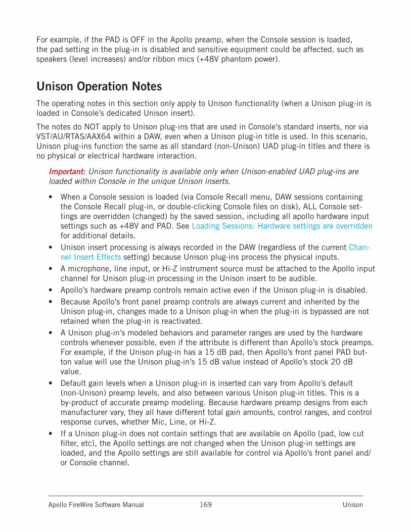
Apollo FireWire Software Manual Unison 169
For example, if the PAD is OFF in the Apollo preamp, when the Console session is loaded, the pad setting in the plug-in is disabled and sensitive equipment could be affected, such as speakers (level increases) and/or ribbon mics (+48V phantom power).
Unison Operation NotesThe operating notes in this section only apply to Unison functionality (when a Unison plug-in is loaded in Console’s dedicated Unison insert).
The notes do NOT apply to Unison plug-ins that are used in Console’s standard inserts, nor via VST/AU/RTAS/AAX64 within a DAW, even when a Unison plug-in title is used. In this scenario, Unison plug-ins function the same as all standard (non-Unison) UAD plug-in titles and there is no physical or electrical hardware interaction.
Important: Unison functionality is available only when Unison-enabled UAD plug-ins are loaded within Console in the unique Unison inserts.
• When a Console session is loaded (via Console Recall menu, DAW sessions containing the Console Recall plug-in, or double-clicking Console files on disk), ALL Console set-tings are overridden (changed) by the saved session, including all apollo hardware input settings such as +48V and PAD. See Loading Sessions: Hardware settings are overridden for additional details.
• Unison insert processing is always recorded in the DAW (regardless of the current Chan-nel Insert Effects setting) because Unison plug-ins process the physical inputs.
• A microphone, line input, or Hi-Z instrument source must be attached to the Apollo input channel for Unison plug-in processing in the Unison insert to be audible.
• Apollo’s hardware preamp controls remain active even if the Unison plug-in is disabled. • Because Apollo’s front panel preamp controls are always current and inherited by the
Unison plug-in, changes made to a Unison plug-in when the plug-in is bypassed are not retained when the plug-in is reactivated.
• A Unison plug-in’s modeled behaviors and parameter ranges are used by the hardware controls whenever possible, even if the attribute is different than Apollo’s stock preamps. For example, if the Unison plug-in has a 15 dB pad, then Apollo’s front panel PAD but-ton value will use the Unison plug-in’s 15 dB value instead of Apollo’s stock 20 dB value.
• Default gain levels when a Unison plug-in is inserted can vary from Apollo’s default (non-Unison) preamp levels, and also between various Unison plug-in titles. This is a by-product of accurate preamp modeling. Because hardware preamp designs from each manufacturer vary, they all have different total gain amounts, control ranges, and control response curves, whether Mic, Line, or Hi-Z.
• If a Unison plug-in does not contain settings that are available on Apollo (pad, low cut filter, etc), the Apollo settings are not changed when the Unison plug-in settings are loaded, and the Apollo settings are still available for control via Apollo’s front panel and/or Console channel.
Apollo FireWire Software Manual Unison 170
• When a Unison plug-in is removed from the Unison insert, Apollo’s mic input impedance reverts to its default value of 5.4K Ohms.
(Continued)
• When the original hardware preamp being emulated by the Unison plug-in has a Hi-Z (instrument) input and associated Hi-Z input switch, this switch is unavailable in the Unison plug-in interface. Instead, the Unison plug-in’s Hi-Z input is automatically se-lected when a mono (tip-sleeve) plug is inserted into the Unison channel’s front panel Hi-Z input jack.
• If Apollo is disconnected from the host computer (standalone mode), the Unison plug-in can no longer be controlled from Apollo’s front panel. However, the signal continues to be processed by the Unison plug-in, using the values that were active when the connec-tion was lost. Note that if Gain Stage Mode is active when the host connection is lost, the gain stage can apparently be switched from the front panel. However, the actual gain stage being controlled does not change.
• Hi-Z input impedance interaction is unavailable with first-generation (silver) Apollo DUO/QUAD/FireWire rackmount models.
• When a channel strip preset is saved from a preamp channel, the channel strip preset contains the state of the preamp channel’s Unison insert.
• When a preamp channel strip preset is loaded into a preamp channel, the Unison insert state is replaced by the Unison instance state in the preamp channel strip preset. For example, if the preamp channel strip preset’s Unison insert is empty, the Unison insert will be empty after loading the preset.
Apollo FireWire Software Manual Latency & Apollo 171
Latency & Apollo
Delay Compensation with Apollo
System Latency OverviewSystem latency encapsulates all latencies induced within the typical digital audio workstation environment. See Latency Basics for a detailed overview of where, when, and how latency is induced in this environment.
Driver ReportingAny system latency that is induced by Apollo’s I/O, Console, and/or UAD Powered Plug-Ins is reported by Apollo’s device drivers to the host audio software that is using the device.
The host software uses this reported device latency for its automatic delay compensation (ADC) engine. When properly configured in the DAW, ADC maintains phase coherency (time alignment) throughout the recording, overdubbing, and mixing process.
Automatic Delay Compensation in the DAWGenerally speaking, ADC should be enabled in the DAW when using Apollo, regardless of whether or not Console is used concurrently. The DAW’s ADC will perform the necessary housekeeping to keep tracks phase-aligned, regardless of the latency source (if any).
Input Delay Compensation in ConsoleConsole has automatic Input Delay Compensation (IDC), which is controlled by the Input Delay Compensation menu in Console Settings. Console IDC maintains phase alignment across all Console’s analog and digital inputs when upsampled UAD plug-ins are used in Console.
For example: If two microphones are used on an acoustic source (such as a drum kit) and an upsampled plug-in is used on one of the mic channels but not the other, without input delay compensation, the phase of the two mic channels would no longer be aligned.
How Console IDC worksConsole IDC automatically adds small amounts of delay to each Console input that is not delayed by upsampled plug-ins, so all Console inputs are still phase aligned. In other words, all compensated inputs are automatically delayed by the same amount.
Apollo FireWire Software Manual Latency & Apollo 172
Upsampled UAD plug-insSome UAD plug-ins are upsampled, meaning their internal sample rate is increased to achieve sonic design goals. When upsampled UAD plug-ins are used in Console, additional latency is induced in the channel(s) using the plug-in(s).
Although the latency added by upsampled UAD plug-ins is negligible (typically between 0-300 samples, depending on the plug-in and sample rate), this extra latency can affect phase coherency in a session.
Note: Upsampling latency is automatically compensated by modern host DAWs.
Upsampled Latency ValuesFor a chart of specific upsampling latency values for UAD plug-ins, see the UAD Plug-Ins Manual.
When To Use Console Input Delay CompensationConsole IDC is required to maintain phase alignment only when BOTH of the following conditions are active:
1. Multiple Console inputs are used for a single source (such as a drum kit using multiple microphones), and
2. Any of those input channels contain upsampled UAD plug-ins.
Tip: When IDC is not needed, disable Console IDC for the lowest possible input latency.
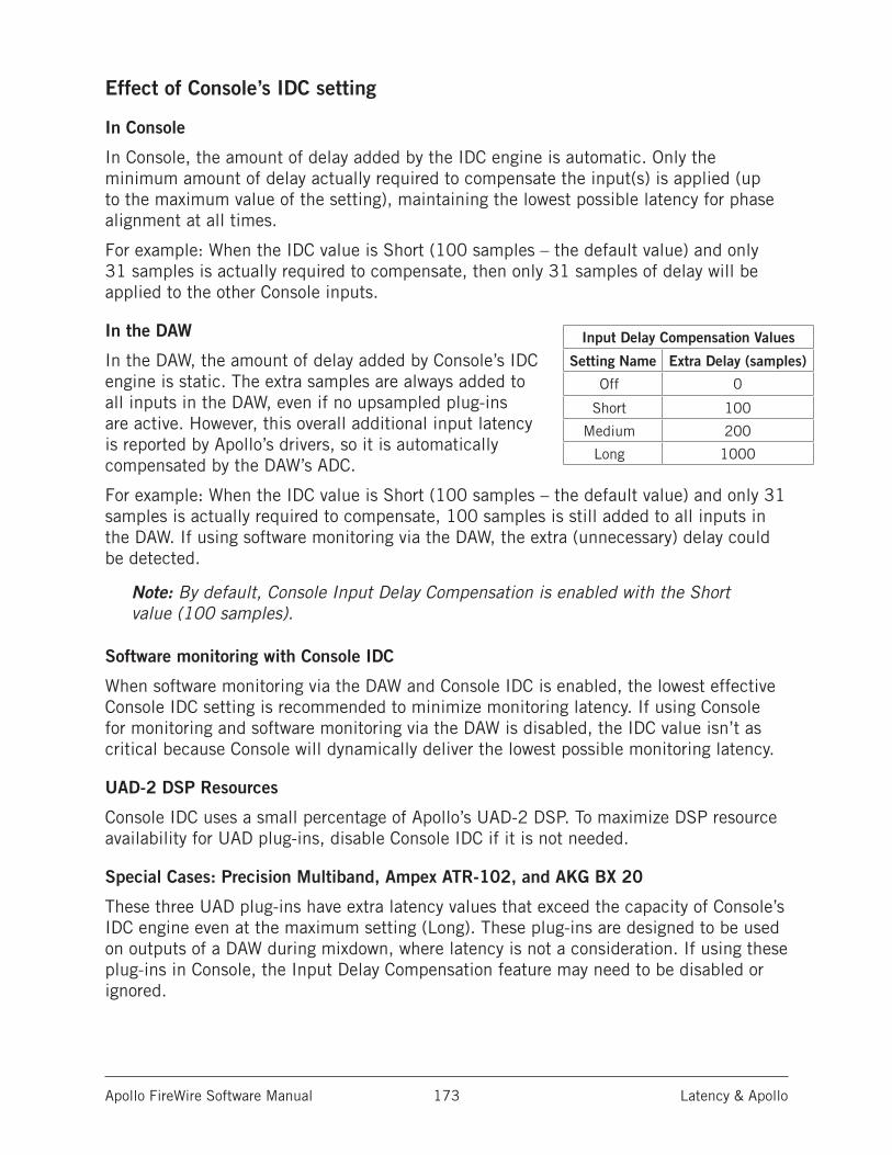
Apollo FireWire Software Manual Latency & Apollo 173
Effect of Console’s IDC setting
In Console
In Console, the amount of delay added by the IDC engine is automatic. Only the minimum amount of delay actually required to compensate the input(s) is applied (up to the maximum value of the setting), maintaining the lowest possible latency for phase alignment at all times.
For example: When the IDC value is Short (100 samples – the default value) and only 31 samples is actually required to compensate, then only 31 samples of delay will be applied to the other Console inputs.
In the DAW
In the DAW, the amount of delay added by Console’s IDC engine is static. The extra samples are always added to all inputs in the DAW, even if no upsampled plug-ins are active. However, this overall additional input latency is reported by Apollo’s drivers, so it is automatically compensated by the DAW’s ADC.
For example: When the IDC value is Short (100 samples – the default value) and only 31 samples is actually required to compensate, 100 samples is still added to all inputs in the DAW. If using software monitoring via the DAW, the extra (unnecessary) delay could be detected.
Note: By default, Console Input Delay Compensation is enabled with the Short value (100 samples).
Software monitoring with Console IDC
When software monitoring via the DAW and Console IDC is enabled, the lowest effective Console IDC setting is recommended to minimize monitoring latency. If using Console for monitoring and software monitoring via the DAW is disabled, the IDC value isn’t as critical because Console will dynamically deliver the lowest possible monitoring latency.
UAD-2 DSP Resources
Console IDC uses a small percentage of Apollo’s UAD-2 DSP. To maximize DSP resource availability for UAD plug-ins, disable Console IDC if it is not needed.
Special Cases: Precision Multiband, Ampex ATR-102, and AKG BX 20
These three UAD plug-ins have extra latency values that exceed the capacity of Console’s IDC engine even at the maximum setting (Long). These plug-ins are designed to be used on outputs of a DAW during mixdown, where latency is not a consideration. If using these plug-ins in Console, the Input Delay Compensation feature may need to be disabled or ignored.
Input Delay Compensation Values
Setting Name Extra Delay (samples)
Off 0
Short 100
Medium 200
Long 1000
Apollo FireWire Software Manual Latency & Apollo 174
Latency BasicsLatency (delay) is an inherent factor in digital audio systems because of A/D-D/A conversion, I/O buffering in the DAW, plug-in signal processing, and other aspects.
Although there are ways to mitigate latency (such as delay compensation and/or low-latency monitoring), it always exists to some degree when working with systems that combine analog and digital audio. These concepts are explained in greater detail below.
Audio Interface LatencyEvery audio interface that performs A/D and/or D/A conversion induces latency as a result of the conversion process. This inherent A/D–D/A latency is essentially undetectable. A/D–D/A latency usually depends on the sample rate, with higher sample rates inducing less latency (higher rates = less time required for conversion).
An audio interface’s “analog I/O round-trip latency” specification refers to how long it takes for an analog signal at an interface input to reappear at the same interface’s analog output after both A/D and D/A conversion. Apollo’s audio interface analog I/O round-trip latency is 1.1 milliseconds at a sample rate of 96 kHz.
Console Mixer LatencyApollo’s Console DSP mixer is used for low-latency monitoring (cue mixing) of Apollo’s analog and digital inputs. Using Console to monitor Apollo’s inputs may or may not add to the inherent analog I/O round-trip latency, depending on how it is configured:
Console without UAD plug-ins – When Console is used without UAD plug-ins, monitoring Apollo’s inputs via Console does not add any latency. In this configuration, Apollo’s analog I/O round-trip latency is still 1.1 milliseconds at 96 kHz.
Console with Realtime UAD Processing – When Console is used for Realtime UAD Processing with UAD Powered Plug-Ins that are not upsampled, monitoring Apollo’s inputs via Console does not add any latency.
In this configuration, Apollo’s analog I/O round-trip latency is still 1.1 milliseconds at 96 kHz, even if up to four UAD (non-upsampled) plug-ins are serially “stacked” (chained) on a single Apollo analog and/or digital input.
Multiple Apollo inputs can have up to four UAD (non-upsampled) plug-ins each (up to the limit of available DSP resources); this configuration also does not add any latency.
Note: Upsampled UAD plug-ins add latency when used in Console or a DAW. See Upsampled UAD plug-ins below for details.
Console Auxiliary Buses – The outputs of the auxiliary buses in Console have 32 samples of additional latency. This is necessary to maintain the lowest possible input latency.
Apollo FireWire Software Manual Latency & Apollo 175
Upsampled UAD Plug-InsSome UAD Powered Plug-Ins are upsampled, meaning their internal sample rate is increased to achieve sonic design goals. Depending on the session sample rate, upsampled UAD plug-ins can add additional latency when used in the Console Mixer and/or a DAW.
Although the latency added by upsampled UAD plug-ins is negligible (typically between 0-300 samples, depending on the plug-in and sample rate), this extra latency can affect phase coherency in a session. However, phase is managed automatically by Input Delay Compensation in Console and Automatic Delay Compensation in the DAW.
Note: For specific upsampling latency values for UAD plug-ins, see the UAD Plug-Ins Manual.
DAW LatencyMost DAWs use I/O buffering to shuttle audio data back and forth between the audio interface and the DAW. This I/O buffering induces additional latency with any audio interface (not just Apollo).
I/O Buffer Size
The amount of DAW latency is usually determined by the DAW’s I/O interface buffer size setting. Low buffer sizes reduce latency, but increase the host computer’s CPU loading. If the buffer size is set too low, host CPU overloads and/or audio artifacts such as clicks, distortion, or dropouts can occur.
Monitoring Live Performance During Recording
DAW latency can be a problem during recording when “software monitoring” via the DAW’s mixer, because the buffering delay is a distraction; an artist cannot hear their performance in realtime. DAW latency when recording with Apollo is mitigated by using the Console Mixer for live performance monitoring, where buffering latency does not apply.
Time-Alignment Of Newly-Recorded Tracks With Previously-Recorded Tracks
Dealing with latency is also important with DAWs for time-alignment of newly-recorded tracks and previously-recorded tracks which are inevitably shifted from the I/O buffering process.
The solution is to use the automatic delay compensation (“ADC”) feature of the DAW. Most modern DAWs, including Console, have automatic delay compensation. For more information about system latency and its compensation, see Delay Compensation with Apollo.
Apollo FireWire Software Manual Latency & Apollo 176
UAD-2 DSP LatencyWhen UAD Powered Plug-Ins are used within a DAW (not Console), I/O buffering is used to shuttle audio data back and forth between the UAD-2 inside Apollo and the DAW, which induces additional latency.
This UAD-2 DSP “DAW processing method” latency is determined by the I/O Buffer Size setting. This latency is unrelated to the (indiscernible) audio interface I/O latency (they are separate processes).
UAD-2 DSP latency makes tracking through UAD plug-ins in the DAW via software monitoring problematic for the performer because again, an artist cannot hear their performance in realtime.
The issue of UAD-2 DSP latency when recording with Apollo is eliminated by using the Console Mixer for live performance monitoring with optional Realtime UAD Processing, where buffering latency does not apply.
Does all this latency stuff really matter?With Apollo, not really. Performance latency is not a factor because of Console’s low latency hardware monitoring; and recording (track alignment) latency during recording, overdubbing, and mixing is automatically compensated by Apollo’s device drivers and the DAW.
Apollo FireWire Software Manual Multi-Unit Cascading 177
Multi-Unit Cascading
Two Apollo or two Apollo 16 units can be cascaded together via FireWire in a multiple-unit configuration. When two Apollo units are connected, both units are controlled within a single Console window, and the I/O complement of both units is available within the DAW. Operating a multi-unit system is nearly identical to that of a single-unit system for seamless expansion when more I/O is needed.
A total of six UAD devices can be used together in a single system.
Note: Combining Apollo with Apollo 16 is an unsupported configuration.
Console IntegrationWhen multi-unit cascading, the number of Console inputs is increased to match the increased hardware inputs. Both Apollo units share the same monitor, auxiliary, and cue mix buses for integrated mixing convenience.
Monitor and Expander Units
To facilitate the mix bus integration within Console, one device must be designated as the monitor (master) unit and the other as the expander (slave) unit. All Console mix bus outputs (monitor, auxiliary, headphone, cue) are available on the monitor unit only.
Tip: Outputs from the DAW can be freely assigned to any Apollo headphone outputs on the master or slave unit via the device drivers.
The designated monitor/expander units can be switched within Console if desired. For details, see Monitor/Expander Designations.
Hardware SetupIn multi-unit setups, specific hardware wiring connections are required, and only the monitor unit is connected to the host computer system. The expander unit is connected to the monitor unit, not the host computer.
The specific connections differ for Apollo and Apollo 16. See Multi-Unit Wiring Diagrams for hardware setup illustrations.
Note: The inter-unit optical cable is required for mix bus integration when multi-unit cascading.
ConstraintsDepending on the specific configuration, certain features and/or I/O streams are reduced when multi-unit cascading. See Multi-Unit Constraints for details.
Driver I/O TablesDriver I/O availability and numbering changes when multi-unit cascading and when PT Mode is enabled. For a complete list of all possible I/O states, see the Driver I/O Tables.
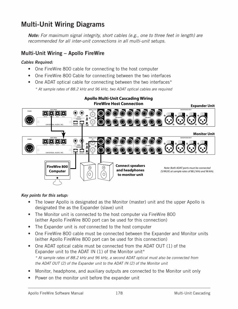
Apollo FireWire Software Manual Multi-Unit Cascading 178
Multi-Unit Wiring DiagramsNote: For maximum signal integrity, short cables (e.g., one to three feet in length) are recommended for all inter-unit connections in all multi-unit setups.
Multi-Unit Wiring – Apollo FireWire
Cables Required:
• One FireWire 800 cable for connecting to the host computer• One FireWire 800 Cable for connecting between the two interfaces• One ADAT optical cable for connecting between the two interfaces*
* At sample rates of 88.2 kHz and 96 kHz, two ADAT optical cables are required
Key points for this setup:
• The lower Apollo is designated as the Monitor (master) unit and the upper Apollo is designated the as the Expander (slave) unit
• The Monitor unit is connected to the host computer via FireWire 800 (either Apollo FireWire 800 port can be used for this connection)
• The Expander unit is not connected to the host computer• One FireWire 800 cable must be connected between the Expander and Monitor units
(either Apollo FireWire 800 port can be used for this connection)• One ADAT optical cable must be connected from the ADAT OUT (1) of the
Expander unit to the ADAT IN (1) of the Monitor unit** At sample rates of 88.2 kHz and 96 kHz, a second ADAT optical must also be connected from the ADAT OUT (2) of the Expander unit to the ADAT IN (2) of the Monitor unit
• Monitor, headphone, and auxiliary outputs are connected to the Monitor unit only• Power on the monitor unit before the expander unit
LINE INPUT
MICROPHONE INPUT
LINE OUTPUTMONITOR
ADAT S/MUXPOWER
1357
2468
1357
2468
1L
R 2
PUSHPUSH PUSH PUSH 1234
S/PDIF
FIREWIRE
INOUT
1394 800 (2) 1394 800 (1)
WORDCLOCK
WORDCLOCK
INWORD CLOCK
OUT75 OHMTERM
IN
OUT
OUT (1)OUT (2) IN (1)IN (2)
UNIVERSAL AUDIO, INC.
LINE INPUT
MICROPHONE INPUT
LINE OUTPUTMONITOR
ADAT S/MUXPOWER
1357
2468
1357
2468
1L
R 2
PUSHPUSH PUSH PUSH 1234
S/PDIF
FIREWIRE
INOUT
1394 800 (2) 1394 800 (1)
WORDCLOCK
WORDCLOCK
INWORD CLOCK
OUT75 OHMTERM
IN
OUT
OUT (1)OUT (2) IN (1)IN (2)
UNIVERSAL AUDIO, INC.
Expander Unit
Monitor Unit
FireWire 800Computer
Connect speakersand headphonesto monitor unit
Note: Both ADAT ports must be connected(S/MUX) at sample rates of 88.2 kHz and 96 kHz.
Apollo Multi-Unit Cascading WiringFireWire Host Connection
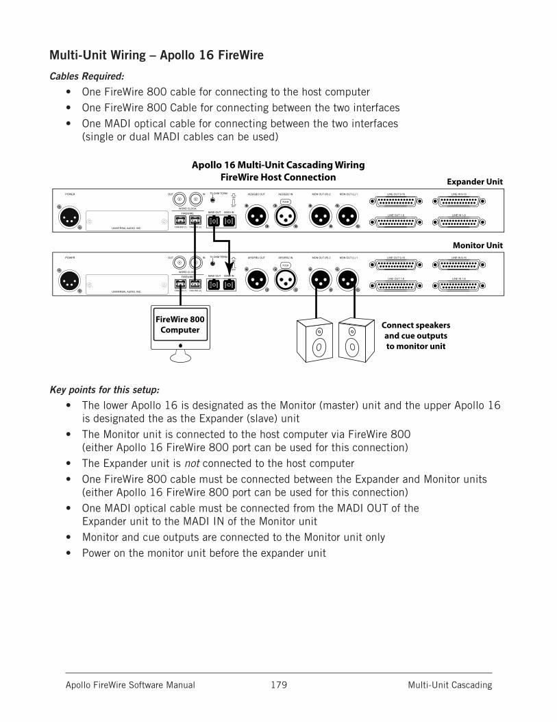
Apollo FireWire Software Manual Multi-Unit Cascading 179
Multi-Unit Wiring – Apollo 16 FireWire
Cables Required:
• One FireWire 800 cable for connecting to the host computer• One FireWire 800 Cable for connecting between the two interfaces• One MADI optical cable for connecting between the two interfaces
(single or dual MADI cables can be used)
Key points for this setup:
• The lower Apollo 16 is designated as the Monitor (master) unit and the upper Apollo 16 is designated the as the Expander (slave) unit
• The Monitor unit is connected to the host computer via FireWire 800 (either Apollo 16 FireWire 800 port can be used for this connection)
• The Expander unit is not connected to the host computer• One FireWire 800 cable must be connected between the Expander and Monitor units
(either Apollo 16 FireWire 800 port can be used for this connection)• One MADI optical cable must be connected from the MADI OUT of the
Expander unit to the MADI IN of the Monitor unit• Monitor and cue outputs are connected to the Monitor unit only• Power on the monitor unit before the expander unit
POWER OUTON
OFF
IN 75 OHM TERM
WORD CLOCK
FIREWIRE
UNIVERSAL AUDIO, INC.
MON OUT (R) 2 MON OUT (L) 1
LINE OUT 1-8 LINE IN 1-8
LINE IN 9-16
MADI OUT MADI IN
AES/EBU OUT AES/EBU IN
PUSH
LINE OUT 9-16
1394 800 (1) 1394 800 (2)
POWER OUTON
OFF
IN 75 OHM TERM
WORD CLOCK
FIREWIRE
UNIVERSAL AUDIO, INC.
MON OUT (R) 2 MON OUT (L) 1
LINE OUT 1-8 LINE IN 1-8
LINE IN 9-16
MADI OUT MADI IN
AES/EBU OUT AES/EBU IN
PUSH
LINE OUT 9-16
1394 800 (1) 1394 800 (2)
Expander Unit
Monitor Unit
FireWire 800Computer Connect speakers
and cue outputsto monitor unit
Apollo 16 Multi-Unit Cascading WiringFireWire Host Connection
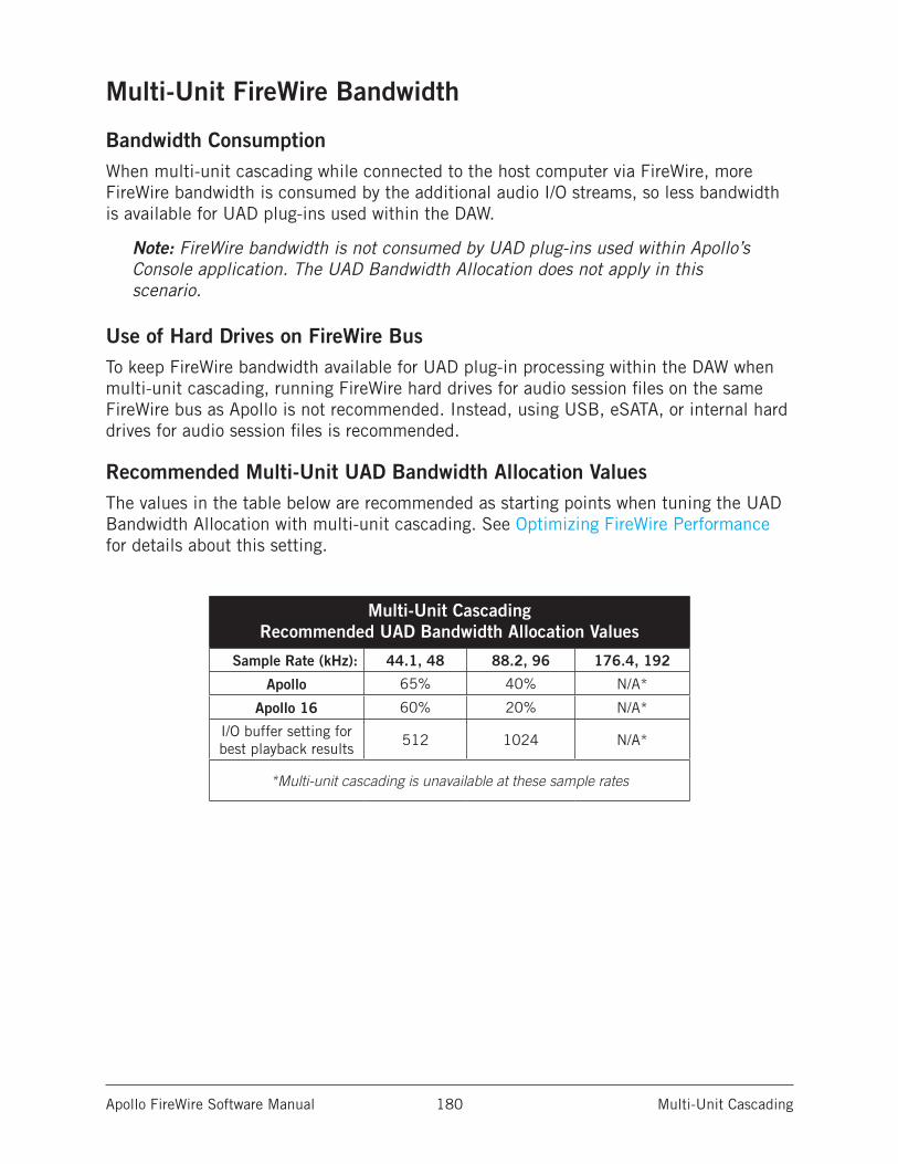
Apollo FireWire Software Manual Multi-Unit Cascading 180
Multi-Unit FireWire Bandwidth
Bandwidth ConsumptionWhen multi-unit cascading while connected to the host computer via FireWire, more FireWire bandwidth is consumed by the additional audio I/O streams, so less bandwidth is available for UAD plug-ins used within the DAW.
Note: FireWire bandwidth is not consumed by UAD plug-ins used within Apollo’s Console application. The UAD Bandwidth Allocation does not apply in this scenario.
Use of Hard Drives on FireWire BusTo keep FireWire bandwidth available for UAD plug-in processing within the DAW when multi-unit cascading, running FireWire hard drives for audio session files on the same FireWire bus as Apollo is not recommended. Instead, using USB, eSATA, or internal hard drives for audio session files is recommended.
Recommended Multi-Unit UAD Bandwidth Allocation ValuesThe values in the table below are recommended as starting points when tuning the UAD Bandwidth Allocation with multi-unit cascading. See Optimizing FireWire Performance for details about this setting.
Multi-Unit Cascading Recommended UAD Bandwidth Allocation Values
Sample Rate (kHz): 44.1, 48 88.2, 96 176.4, 192
Apollo 65% 40% N/A*
Apollo 16 60% 20% N/A*
I/O buffer setting for best playback results
512 1024 N/A*
*Multi-unit cascading is unavailable at these sample rates
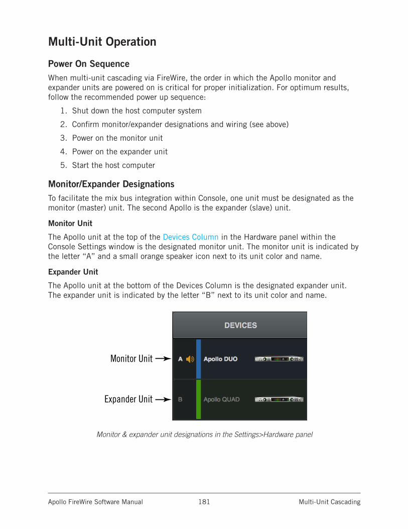
Apollo FireWire Software Manual Multi-Unit Cascading 181
Multi-Unit Operation
Power On SequenceWhen multi-unit cascading via FireWire, the order in which the Apollo monitor and expander units are powered on is critical for proper initialization. For optimum results, follow the recommended power up sequence:
1. Shut down the host computer system
2. Confirm monitor/expander designations and wiring (see above)
3. Power on the monitor unit
4. Power on the expander unit
5. Start the host computer
Monitor/Expander DesignationsTo facilitate the mix bus integration within Console, one unit must be designated as the monitor (master) unit. The second Apollo is the expander (slave) unit.
Monitor Unit
The Apollo unit at the top of the Devices Column in the Hardware panel within the Console Settings window is the designated monitor unit. The monitor unit is indicated by the letter “A” and a small orange speaker icon next to its unit color and name.
Expander Unit
The Apollo unit at the bottom of the Devices Column is the designated expander unit. The expander unit is indicated by the letter “B” next to its unit color and name.
Monitor & expander unit designations in the Settings>Hardware panel
Monitor Unit
Expander Unit
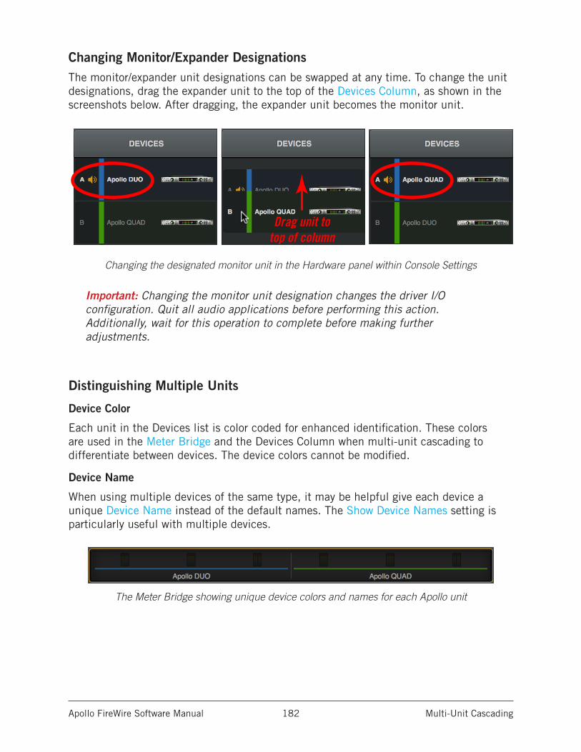
Apollo FireWire Software Manual Multi-Unit Cascading 182
Changing Monitor/Expander DesignationsThe monitor/expander unit designations can be swapped at any time. To change the unit designations, drag the expander unit to the top of the Devices Column, as shown in the screenshots below. After dragging, the expander unit becomes the monitor unit.
Changing the designated monitor unit in the Hardware panel within Console Settings
Important: Changing the monitor unit designation changes the driver I/O configuration. Quit all audio applications before performing this action. Additionally, wait for this operation to complete before making further adjustments.
Distinguishing Multiple Units
Device Color
Each unit in the Devices list is color coded for enhanced identification. These colors are used in the Meter Bridge and the Devices Column when multi-unit cascading to differentiate between devices. The device colors cannot be modified.
Device Name
When using multiple devices of the same type, it may be helpful give each device a unique Device Name instead of the default names. The Show Device Names setting is particularly useful with multiple devices.
The Meter Bridge showing unique device colors and names for each Apollo unit
Drag unit totop of column
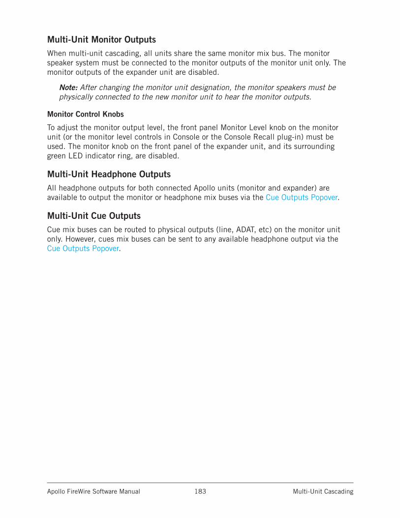
Apollo FireWire Software Manual Multi-Unit Cascading 183
Multi-Unit Monitor OutputsWhen multi-unit cascading, all units share the same monitor mix bus. The monitor speaker system must be connected to the monitor outputs of the monitor unit only. The monitor outputs of the expander unit are disabled.
Note: After changing the monitor unit designation, the monitor speakers must be physically connected to the new monitor unit to hear the monitor outputs.
Monitor Control Knobs
To adjust the monitor output level, the front panel Monitor Level knob on the monitor unit (or the monitor level controls in Console or the Console Recall plug-in) must be used. The monitor knob on the front panel of the expander unit, and its surrounding green LED indicator ring, are disabled.
Multi-Unit Headphone OutputsAll headphone outputs for both connected Apollo units (monitor and expander) are available to output the monitor or headphone mix buses via the Cue Outputs Popover.
Multi-Unit Cue OutputsCue mix buses can be routed to physical outputs (line, ADAT, etc) on the monitor unit only. However, cues mix buses can be sent to any available headphone output via the Cue Outputs Popover.
Apollo FireWire Software Manual Multi-Unit Cascading 184
Multi-Unit Clocking
InternalWhen the units are connected according to the Multi-Unit Wiring Diagrams, all system clocking and clock settings are automatically configured by Apollo’s device drivers. The clock setting in Console’s Info Bar (and its mirrored setting in the Hardware panel within the Console Settings window) must remain on INTERNAL unless specifically clocking to an external (non-Apollo) device.
Note: When Apollo’s clock source is set to INTERNAL, “EXT” will illuminate on the front panel hardware of the expander unit.
ExternalWhen using an external (non-Apollo) clock, connect the external clock to the monitor unit only. All connected Apollo units are automatically configured to use the external clock when Apollo’s Clock is set to EXTERNAL.
Important: When synchronizing to external clock, connect the external clock source to the monitor unit only. The expander unit always synchronizes to the monitor unit.
Multi-Unit Flex RoutingWhen multi-unit cascading, Flex Routing can be used within each unit. Up to eight output routes can be assigned for each connected Apollo rack model.
Note: Inputs can only be routed to the outputs of the same unit. It’s not possible to cross-route from one unit to another.
Apollo FireWire Software Manual Multi-Unit Cascading 185
Console Session Management
Console 1 to Console 2 SessionIf a FireWire Console session was created and saved with Console 1 (UAD v9.0 or earlier software) and the session is subsequently opened with a multi-unit FireWire setup in Console 2 (UAD v9.1 or later software), the previous Console 1 configuration is retained, with the exception noted below.
Note: Cue and headphone management settings are handled differently in Console 2 sessions. These settings are not retained when updating a Console 1 session.
Single-to-Multi SessionIf a Console session was created and saved with a single-unit setup and the session is subsequently opened with a multi-unit setup, the expander unit is automatically added to the session and the number of Console inputs expands accordingly. All settings from the single-unit session are maintained.
Multi-to-Single SessionIf a Console session was created and saved with a multi-unit setup and the session is subsequently opened with a single-unit setup, the expander unit is retained in the session for offline configuration. The expander unit can be removed from the session via the Devices Column if desired.
Apollo FireWire Software Manual Multi-Unit Cascading 186
Multi-Unit ConstraintsCertain features and/or I/O streams are reduced when multi-unit cascading due to limited audio bandwidth or technical constraints required to maintain integrated mix buses with Realtime UAD Processing capabilities. These constraints are listed below.
Available Outputs• All Console mix bus outputs (monitor, auxiliary, headphone, cue) are available on
the monitor unit only.
Tip: Outputs from the DAW can be freely assigned to any Apollo headphone outputs on the master or slave unit via the device drivers.
Auxiliary 2 (Apollo only)• Aux bus 2 is unavailable when multi-unit cascading with Apollo.
High Sample Rates
176.4 kHz and 192 kHz
• Multi-unit cascading is unavailable at sample rates of 176.4 kHz or 192 kHz.
Note: Some DAWs (e.g., Ableton Live, Steinberg Cubase) allow switching to these high sample rates even though they are not supported with Apollo FireWire multi-unit cascading. If these DAWs are switched to 176.4 kHz or 192 kHz sample rates when multi-unit cascading, you may need to connect only a single Apollo unit in order to reconfigure the DAW to a lower sample rate.
88.2 kHz and 96 kHz (Apollo only)
• Both ADAT ports must be used for S/MUX connections when multi-unit cascading at sample rates of 88.2 kHz or 96 kHz.
PT Mode• Avid Pro Tools allows 32 channels of I/O with non-Avid branded audio interfaces.
Because audio streams exceed this count when multi-unit cascading, some Apollo I/O channels are unavailable in PT Mode when multi-unit cascading. The specific Apollo channel numbers and names that are available when PT Mode is active are listed in the Driver I/O Tables.
Combining Different Apollo Models• Combining Apollo FireWire with Apollo 16 FireWire is an unsupported
configuration.• Apollo FireWire and/or Apollo 16 FireWire units cannot be combined with Apollo
units that use Thunderbolt or USB connections. All connected Apollo models must use the same connection protocol.
Apollo FireWire Software Manual Device Drivers 187
Device Drivers
Apollo Drivers OverviewThe Apollo device drivers are the low-level software files that instruct the computer’s operating system on how to communicate with the Apollo hardware. The drivers are loaded during system startup so that whenever Apollo is connected, the device is ready to accept instructions from the OS. Apollo’s drivers control Apollo’s audio interface, Console Mixer, and UAD-2 functional-ity.
Core Audio and ASIO
Apollo’s audio drivers use the Core Audio (Mac) and ASIO (Windows) APIs. Apollo’s normal (non-DSP) audio interface features are simply seen as Core Audio or ASIO device; therefore any Core Audio/ASIO-compliant software can use Apollo for audio I/O.
UAD Mixer Engine
The Console application and Console Recall plug-in don’t actually communicate directly with Apollo. Instead, they communicate with the UAD Mixer Engine, which is the central software hub for all Console and Console Recall functionality. The UAD Mixer Engine behaves as a server for Apollo’s internal DSP mixer that runs in the background, so Console does not have to be open for Apollo to function.
The UAD Mixer Engine is a system-level application that is automatically launched during sys-tem startup and is always running during normal operation. The UAD System Menu is it’s only interface, which can be accessed from the OS X Menu Bar (Mac), or the System Tray (Windows).
Driver I/O Complement
The specific inputs and outputs that are available to the DAW depends on the active configura-tion. The I/O complement changes when PT Mode is enabled, at high sample rates, and when multi-unit cascading. The specific I/O complements are listed in the Driver I/O Tables in this chapter.
Driver Names and Numbers
Apollo’s drivers describe all I/O channels by name and number, but what is actually displayed in the DAW’s I/O assignment lists depends on each particular DAW. Names are not displayed by all DAWs (e.g., Ableton Live), or the driver name display mode may need to be changed in the DAW (e.g., Apple Logic Pro).
Virtual I/O
Apollo’s device drivers carry various virtual (software only) input and output channels in addition to those directly associated with the hardware inputs and outputs. The virtual channels consist of all of Apollo’s bus outputs (the main monitor mix and all channel send mixes) and Console’s virtual inputs. Virtual I/O facilitates highly flexible signal routing via the DAW. See Virtual I/O for details about this feature.
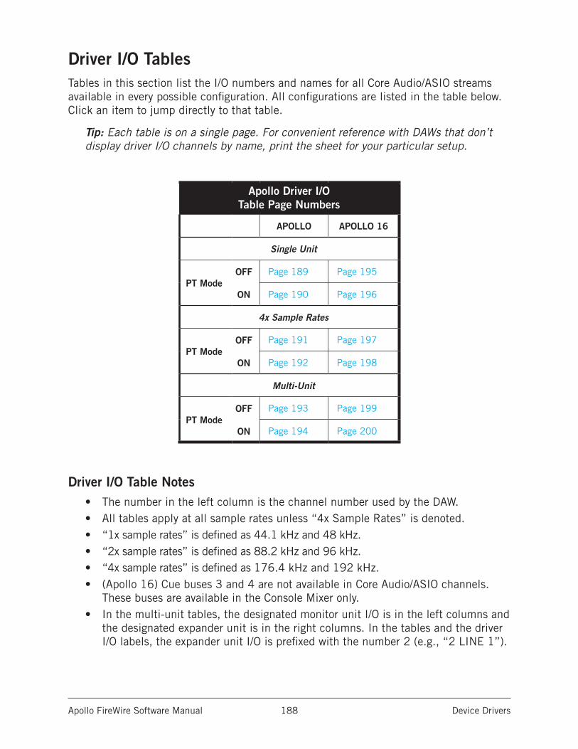
Apollo FireWire Software Manual Device Drivers 188
Driver I/O TablesTables in this section list the I/O numbers and names for all Core Audio/ASIO streams available in every possible configuration. All configurations are listed in the table below. Click an item to jump directly to that table.
Tip: Each table is on a single page. For convenient reference with DAWs that don’t display driver I/O channels by name, print the sheet for your particular setup.
Apollo Driver I/O Table Page Numbers
APOLLO APOLLO 16
Single Unit
PT ModeOFF Page 189 Page 195
ON Page 190 Page 196
4x Sample Rates
PT ModeOFF Page 191 Page 197
ON Page 192 Page 198
Multi-Unit
PT ModeOFF Page 193 Page 199
ON Page 194 Page 200
Driver I/O Table Notes• The number in the left column is the channel number used by the DAW.• All tables apply at all sample rates unless “4x Sample Rates” is denoted.• “1x sample rates” is defined as 44.1 kHz and 48 kHz.• “2x sample rates” is defined as 88.2 kHz and 96 kHz.• “4x sample rates” is defined as 176.4 kHz and 192 kHz.• (Apollo 16) Cue buses 3 and 4 are not available in Core Audio/ASIO channels.
These buses are available in the Console Mixer only. • In the multi-unit tables, the designated monitor unit I/O is in the left columns and
the designated expander unit is in the right columns. In the tables and the driver I/O labels, the expander unit I/O is prefixed with the number 2 (e.g., “2 LINE 1”).
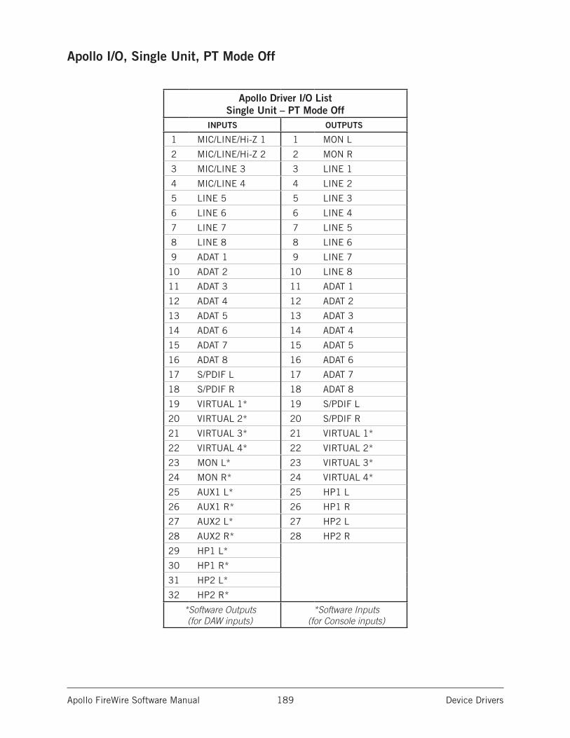
Apollo FireWire Software Manual Device Drivers 189
Apollo I/O, Single Unit, PT Mode Off
Apollo Driver I/O List Single Unit – PT Mode Off
INPUTS OUTPUTS
1 MIC/LINE/Hi-Z 1 1 MON L
2 MIC/LINE/Hi-Z 2 2 MON R
3 MIC/LINE 3 3 LINE 1
4 MIC/LINE 4 4 LINE 2
5 LINE 5 5 LINE 3
6 LINE 6 6 LINE 4
7 LINE 7 7 LINE 5
8 LINE 8 8 LINE 6
9 ADAT 1 9 LINE 7
10 ADAT 2 10 LINE 8
11 ADAT 3 11 ADAT 1
12 ADAT 4 12 ADAT 2
13 ADAT 5 13 ADAT 3
14 ADAT 6 14 ADAT 4
15 ADAT 7 15 ADAT 5
16 ADAT 8 16 ADAT 6
17 S/PDIF L 17 ADAT 7
18 S/PDIF R 18 ADAT 8
19 VIRTUAL 1* 19 S/PDIF L
20 VIRTUAL 2* 20 S/PDIF R
21 VIRTUAL 3* 21 VIRTUAL 1*
22 VIRTUAL 4* 22 VIRTUAL 2*
23 MON L* 23 VIRTUAL 3*
24 MON R* 24 VIRTUAL 4*
25 AUX1 L* 25 HP1 L
26 AUX1 R* 26 HP1 R
27 AUX2 L* 27 HP2 L
28 AUX2 R* 28 HP2 R
29 HP1 L*
30 HP1 R*
31 HP2 L*
32 HP2 R*
*Software Outputs (for DAW inputs)
*Software Inputs (for Console inputs)
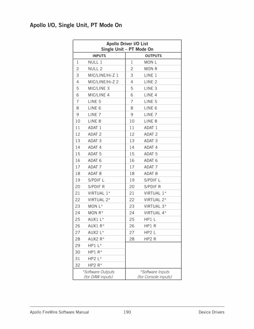
Apollo FireWire Software Manual Device Drivers 190
Apollo I/O, Single Unit, PT Mode On
Apollo Driver I/O List Single Unit – PT Mode On
INPUTS OUTPUTS
1 NULL 1 1 MON L
2 NULL 2 2 MON R
3 MIC/LINE/Hi-Z 1 3 LINE 1
4 MIC/LINE/Hi-Z 2 4 LINE 2
5 MIC/LINE 3 5 LINE 3
6 MIC/LINE 4 6 LINE 4
7 LINE 5 7 LINE 5
8 LINE 6 8 LINE 6
9 LINE 7 9 LINE 7
10 LINE 8 10 LINE 8
11 ADAT 1 11 ADAT 1
12 ADAT 2 12 ADAT 2
13 ADAT 3 13 ADAT 3
14 ADAT 4 14 ADAT 4
15 ADAT 5 15 ADAT 5
16 ADAT 6 16 ADAT 6
17 ADAT 7 17 ADAT 7
18 ADAT 8 18 ADAT 8
19 S/PDIF L 19 S/PDIF L
20 S/PDIF R 20 S/PDIF R
21 VIRTUAL 1* 21 VIRTUAL 1*
22 VIRTUAL 2* 22 VIRTUAL 2*
23 MON L* 23 VIRTUAL 3*
24 MON R* 24 VIRTUAL 4*
25 AUX1 L* 25 HP1 L
26 AUX1 R* 26 HP1 R
27 AUX2 L* 27 HP2 L
28 AUX2 R* 28 HP2 R
29 HP1 L*
30 HP1 R*
31 HP2 L*
32 HP2 R*
*Software Outputs (for DAW inputs)
*Software Inputs (for Console inputs)
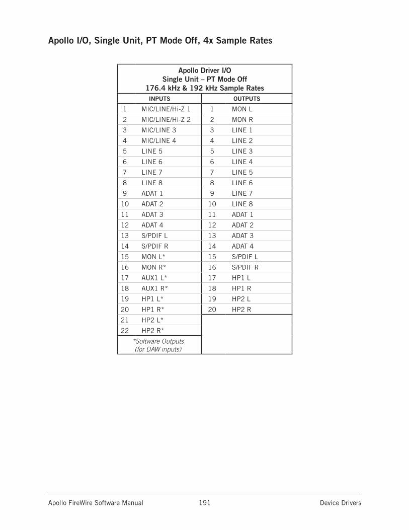
Apollo FireWire Software Manual Device Drivers 191
Apollo I/O, Single Unit, PT Mode Off, 4x Sample Rates
Apollo Driver I/O Single Unit – PT Mode Off
176.4 kHz & 192 kHz Sample RatesINPUTS OUTPUTS
1 MIC/LINE/Hi-Z 1 1 MON L
2 MIC/LINE/Hi-Z 2 2 MON R
3 MIC/LINE 3 3 LINE 1
4 MIC/LINE 4 4 LINE 2
5 LINE 5 5 LINE 3
6 LINE 6 6 LINE 4
7 LINE 7 7 LINE 5
8 LINE 8 8 LINE 6
9 ADAT 1 9 LINE 7
10 ADAT 2 10 LINE 8
11 ADAT 3 11 ADAT 1
12 ADAT 4 12 ADAT 2
13 S/PDIF L 13 ADAT 3
14 S/PDIF R 14 ADAT 4
15 MON L* 15 S/PDIF L
16 MON R* 16 S/PDIF R
17 AUX1 L* 17 HP1 L
18 AUX1 R* 18 HP1 R
19 HP1 L* 19 HP2 L
20 HP1 R* 20 HP2 R
21 HP2 L*
22 HP2 R*
*Software Outputs (for DAW inputs)
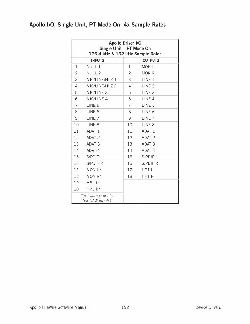
Apollo FireWire Software Manual Device Drivers 192
Apollo I/O, Single Unit, PT Mode On, 4x Sample Rates
Apollo Driver I/O Single Unit – PT Mode On
176.4 kHz & 192 kHz Sample RatesINPUTS OUTPUTS
1 NULL 1 1 MON L
2 NULL 2 2 MON R
3 MIC/LINE/Hi-Z 1 3 LINE 1
4 MIC/LINE/Hi-Z 2 4 LINE 2
5 MIC/LINE 3 5 LINE 3
6 MIC/LINE 4 6 LINE 4
7 LINE 5 7 LINE 5
8 LINE 6 8 LINE 6
9 LINE 7 9 LINE 7
10 LINE 8 10 LINE 8
11 ADAT 1 11 ADAT 1
12 ADAT 2 12 ADAT 2
13 ADAT 3 13 ADAT 3
14 ADAT 4 14 ADAT 4
15 S/PDIF L 15 S/PDIF L
16 S/PDIF R 16 S/PDIF R
17 MON L* 17 HP1 L
18 MON R* 18 HP1 R
19 HP1 L*
20 HP1 R*
*Software Outputs (for DAW inputs)
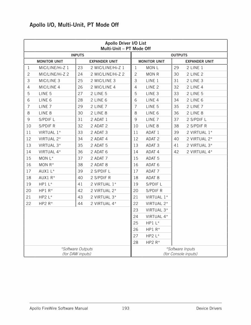
Apollo FireWire Software Manual Device Drivers 193
Apollo I/O, Multi-Unit, PT Mode Off
Apollo Driver I/O List Multi-Unit – PT Mode Off
INPUTS OUTPUTS
MONITOR UNIT EXPANDER UNIT MONITOR UNIT EXPANDER UNIT
1 MIC/LINE/Hi-Z 1 23 2 MIC/LINE/Hi-Z 1 1 MON L 29 2 LINE 1
2 MIC/LINE/Hi-Z 2 24 2 MIC/LINE/Hi-Z 2 2 MON R 30 2 LINE 2
3 MIC/LINE 3 25 2 MIC/LINE 3 3 LINE 1 31 2 LINE 3
4 MIC/LINE 4 26 2 MIC/LINE 4 4 LINE 2 32 2 LINE 4
5 LINE 5 27 2 LINE 5 5 LINE 3 33 2 LINE 5
6 LINE 6 28 2 LINE 6 6 LINE 4 34 2 LINE 6
7 LINE 7 29 2 LINE 7 7 LINE 5 35 2 LINE 7
8 LINE 8 30 2 LINE 8 8 LINE 6 36 2 LINE 8
9 S/PDIF L 31 2 ADAT 1 9 LINE 7 37 2 S/PDIF L
10 S/PDIF R 32 2 ADAT 2 10 LINE 8 38 2 S/PDIF R
11 VIRTUAL 1* 33 2 ADAT 3 11 ADAT 1 39 2 VIRTUAL 1*
12 VIRTUAL 2* 34 2 ADAT 4 12 ADAT 2 40 2 VIRTUAL 2*
13 VIRTUAL 3* 35 2 ADAT 5 13 ADAT 3 41 2 VIRTUAL 3*
14 VIRTUAL 4* 36 2 ADAT 6 14 ADAT 4 42 2 VIRTUAL 4*
15 MON L* 37 2 ADAT 7 15 ADAT 5
16 MON R* 38 2 ADAT 8 16 ADAT 6
17 AUX1 L* 39 2 S/PDIF L 17 ADAT 7
18 AUX1 R* 40 2 S/PDIF R 18 ADAT 8
19 HP1 L* 41 2 VIRTUAL 1* 19 S/PDIF L
20 HP1 R* 42 2 VIRTUAL 2* 20 S/PDIF R
21 HP2 L* 43 2 VIRTUAL 3* 21 VIRTUAL 1*
22 HP2 R* 44 2 VIRTUAL 4* 22 VIRTUAL 2*
23 VIRTUAL 3*
24 VIRTUAL 4*
25 HP1 L*
26 HP1 R*
27 HP2 L*
28 HP2 R*
*Software Outputs (for DAW inputs)
*Software Inputs (for Console inputs)
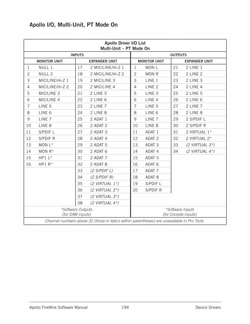
Apollo FireWire Software Manual Device Drivers 194
Apollo I/O, Multi-Unit, PT Mode On
Apollo Driver I/O List Multi-Unit – PT Mode On
INPUTS OUTPUTS
MONITOR UNIT EXPANDER UNIT MONITOR UNIT EXPANDER UNIT
1 NULL 1 17 2 MIC/LINE/Hi-Z 1 1 MON L 21 2 LINE 1
2 NULL 2 18 2 MIC/LINE/Hi-Z 2 2 MON R 22 2 LINE 2
3 MIC/LINE/Hi-Z 1 19 2 MIC/LINE 3 3 LINE 1 23 2 LINE 3
4 MIC/LINE/Hi-Z 2 20 2 MIC/LINE 4 4 LINE 2 24 2 LINE 4
5 MIC/LINE 3 21 2 LINE 5 5 LINE 3 25 2 LINE 5
6 MIC/LINE 4 22 2 LINE 6 6 LINE 4 26 2 LINE 6
7 LINE 5 23 2 LINE 7 7 LINE 5 27 2 LINE 7
8 LINE 6 24 2 LINE 8 8 LINE 6 28 2 LINE 8
9 LINE 7 25 2 ADAT 1 9 LINE 7 29 2 S/PDIF L
10 LINE 8 26 2 ADAT 2 10 LINE 8 30 2 S/PDIF R
11 S/PDIF L 27 2 ADAT 3 11 ADAT 1 31 2 VIRTUAL 1*
12 S/PDIF R 28 2 ADAT 4 12 ADAT 2 32 2 VIRTUAL 2*
13 MON L* 29 2 ADAT 5 13 ADAT 3 33 (2 VIRTUAL 3*)
14 MON R* 30 2 ADAT 6 14 ADAT 4 34 (2 VIRTUAL 4*)
15 HP1 L* 31 2 ADAT 7 15 ADAT 5
16 HP1 R* 32 2 ADAT 8 16 ADAT 6
33 (2 S/PDIF L) 17 ADAT 7
34 (2 S/PDIF R) 18 ADAT 8
35 (2 VIRTUAL 1*) 19 S/PDIF L
36 (2 VIRTUAL 2*) 20 S/PDIF R
37 (2 VIRTUAL 3*)
38 (2 VIRTUAL 4*)
*Software Outputs (for DAW inputs)
*Software Inputs (for Console inputs)
Channel numbers above 32 (those in italics within parentheses) are unavailable in Pro Tools

Apollo FireWire Software Manual Device Drivers 195
Apollo 16 I/O, Single Unit, PT Mode Off
Apollo 16 Driver I/O List Single Unit – PT Mode Off
INPUTS OUTPUTS
1 LINE 1 1 MON L
2 LINE 2 2 MON R
3 LINE 3 3 LINE 1
4 LINE 4 4 LINE 2
5 LINE 5 5 LINE 3
6 LINE 6 6 LINE 4
7 LINE 7 7 LINE 5
8 LINE 8 8 LINE 6
9 LINE 9 9 LINE 7
10 LINE 10 10 LINE 8
11 LINE 11 11 LINE 9
12 LINE 12 12 LINE 10
13 LINE 13 13 LINE 11
14 LINE 14 14 LINE 12
15 LINE 15 15 LINE 13
16 LINE 16 16 LINE 14
17 AES/EBU L 17 LINE 15
18 AES/EBU R 18 LINE 16
19 VIRTUAL 1* 19 AES/EBU L
20 VIRTUAL 2* 20 AES/EBU R
21 VIRTUAL 3* 21 VIRTUAL 1*
22 VIRTUAL 4* 22 VIRTUAL 2*
23 VIRTUAL 5* 23 VIRTUAL 3*
24 VIRTUAL 6* 24 VIRTUAL 4*
25 VIRTUAL 7* 25 VIRTUAL 5*
26 VIRTUAL 8* 26 VIRTUAL 6*
27 MON L* 27 VIRTUAL 7*
28 MON R* 28 VIRTUAL 8*
29 AUX1 L* 29 CUE 1 L
30 AUX1 R* 30 CUE 1 R
31 AUX2 L* 31 CUE 2 L
32 AUX2 R* 32 CUE 2 R
*Software Outputs (for DAW inputs)
*Software Inputs (for Console inputs)
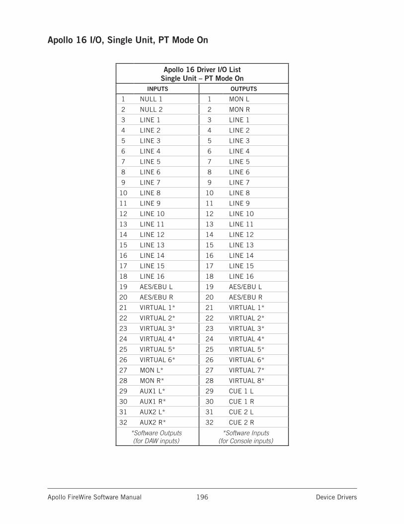
Apollo FireWire Software Manual Device Drivers 196
Apollo 16 I/O, Single Unit, PT Mode On
Apollo 16 Driver I/O List Single Unit – PT Mode On
INPUTS OUTPUTS
1 NULL 1 1 MON L
2 NULL 2 2 MON R
3 LINE 1 3 LINE 1
4 LINE 2 4 LINE 2
5 LINE 3 5 LINE 3
6 LINE 4 6 LINE 4
7 LINE 5 7 LINE 5
8 LINE 6 8 LINE 6
9 LINE 7 9 LINE 7
10 LINE 8 10 LINE 8
11 LINE 9 11 LINE 9
12 LINE 10 12 LINE 10
13 LINE 11 13 LINE 11
14 LINE 12 14 LINE 12
15 LINE 13 15 LINE 13
16 LINE 14 16 LINE 14
17 LINE 15 17 LINE 15
18 LINE 16 18 LINE 16
19 AES/EBU L 19 AES/EBU L
20 AES/EBU R 20 AES/EBU R
21 VIRTUAL 1* 21 VIRTUAL 1*
22 VIRTUAL 2* 22 VIRTUAL 2*
23 VIRTUAL 3* 23 VIRTUAL 3*
24 VIRTUAL 4* 24 VIRTUAL 4*
25 VIRTUAL 5* 25 VIRTUAL 5*
26 VIRTUAL 6* 26 VIRTUAL 6*
27 MON L* 27 VIRTUAL 7*
28 MON R* 28 VIRTUAL 8*
29 AUX1 L* 29 CUE 1 L
30 AUX1 R* 30 CUE 1 R
31 AUX2 L* 31 CUE 2 L
32 AUX2 R* 32 CUE 2 R
*Software Outputs (for DAW inputs)
*Software Inputs (for Console inputs)
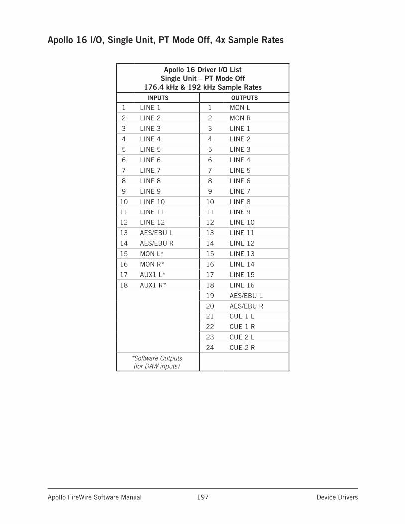
Apollo FireWire Software Manual Device Drivers 197
Apollo 16 I/O, Single Unit, PT Mode Off, 4x Sample Rates
Apollo 16 Driver I/O List Single Unit – PT Mode Off
176.4 kHz & 192 kHz Sample RatesINPUTS OUTPUTS
1 LINE 1 1 MON L
2 LINE 2 2 MON R
3 LINE 3 3 LINE 1
4 LINE 4 4 LINE 2
5 LINE 5 5 LINE 3
6 LINE 6 6 LINE 4
7 LINE 7 7 LINE 5
8 LINE 8 8 LINE 6
9 LINE 9 9 LINE 7
10 LINE 10 10 LINE 8
11 LINE 11 11 LINE 9
12 LINE 12 12 LINE 10
13 AES/EBU L 13 LINE 11
14 AES/EBU R 14 LINE 12
15 MON L* 15 LINE 13
16 MON R* 16 LINE 14
17 AUX1 L* 17 LINE 15
18 AUX1 R* 18 LINE 16
19 AES/EBU L
20 AES/EBU R
21 CUE 1 L
22 CUE 1 R
23 CUE 2 L
24 CUE 2 R
*Software Outputs (for DAW inputs)
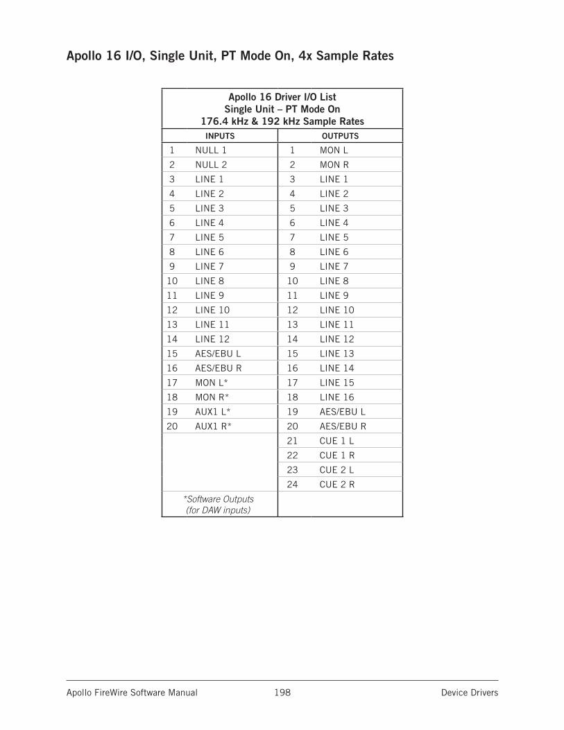
Apollo FireWire Software Manual Device Drivers 198
Apollo 16 I/O, Single Unit, PT Mode On, 4x Sample Rates
Apollo 16 Driver I/O List Single Unit – PT Mode On
176.4 kHz & 192 kHz Sample RatesINPUTS OUTPUTS
1 NULL 1 1 MON L
2 NULL 2 2 MON R
3 LINE 1 3 LINE 1
4 LINE 2 4 LINE 2
5 LINE 3 5 LINE 3
6 LINE 4 6 LINE 4
7 LINE 5 7 LINE 5
8 LINE 6 8 LINE 6
9 LINE 7 9 LINE 7
10 LINE 8 10 LINE 8
11 LINE 9 11 LINE 9
12 LINE 10 12 LINE 10
13 LINE 11 13 LINE 11
14 LINE 12 14 LINE 12
15 AES/EBU L 15 LINE 13
16 AES/EBU R 16 LINE 14
17 MON L* 17 LINE 15
18 MON R* 18 LINE 16
19 AUX1 L* 19 AES/EBU L
20 AUX1 R* 20 AES/EBU R
21 CUE 1 L
22 CUE 1 R
23 CUE 2 L
24 CUE 2 R
*Software Outputs (for DAW inputs)
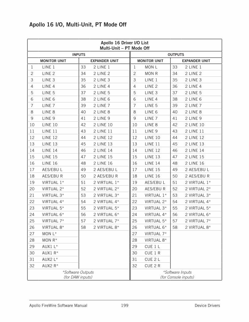
Apollo FireWire Software Manual Device Drivers 199
Apollo 16 I/O, Multi-Unit, PT Mode Off
Apollo 16 Driver I/O List Multi-Unit – PT Mode Off
INPUTS OUTPUTS
MONITOR UNIT EXPANDER UNIT MONITOR UNIT EXPANDER UNIT
1 LINE 1 33 2 LINE 1 1 MON L 33 2 LINE 1
2 LINE 2 34 2 LINE 2 2 MON R 34 2 LINE 2
3 LINE 3 35 2 LINE 3 3 LINE 1 35 2 LINE 3
4 LINE 4 36 2 LINE 4 4 LINE 2 36 2 LINE 4
5 LINE 5 37 2 LINE 5 5 LINE 3 37 2 LINE 5
6 LINE 6 38 2 LINE 6 6 LINE 4 38 2 LINE 6
7 LINE 7 39 2 LINE 7 7 LINE 5 39 2 LINE 7
8 LINE 8 40 2 LINE 8 8 LINE 6 40 2 LINE 8
9 LINE 9 41 2 LINE 9 9 LINE 7 41 2 LINE 9
10 LINE 10 42 2 LINE 10 10 LINE 8 42 2 LINE 10
11 LINE 11 43 2 LINE 11 11 LINE 9 43 2 LINE 11
12 LINE 12 44 2 LINE 12 12 LINE 10 44 2 LINE 12
13 LINE 13 45 2 LINE 13 13 LINE 11 45 2 LINE 13
14 LINE 14 46 2 LINE 14 14 LINE 12 46 2 LINE 14
15 LINE 15 47 2 LINE 15 15 LINE 13 47 2 LINE 15
16 LINE 16 48 2 LINE 16 16 LINE 14 48 2 LINE 16
17 AES/EBU L 49 2 AES/EBU L 17 LINE 15 49 2 AES/EBU L
18 AES/EBU R 50 2 AES/EBU R 18 LINE 16 50 2 AES/EBU R
19 VIRTUAL 1* 51 2 VIRTUAL 1* 19 AES/EBU L 51 2 VIRTUAL 1*
20 VIRTUAL 2* 52 2 VIRTUAL 2* 20 AES/EBU R 52 2 VIRTUAL 2*
21 VIRTUAL 3* 53 2 VIRTUAL 3* 21 VIRTUAL 1* 53 2 VIRTUAL 3*
22 VIRTUAL 4* 54 2 VIRTUAL 4* 22 VIRTUAL 2* 54 2 VIRTUAL 4*
23 VIRTUAL 5* 55 2 VIRTUAL 5* 23 VIRTUAL 3* 55 2 VIRTUAL 5*
24 VIRTUAL 6* 56 2 VIRTUAL 6* 24 VIRTUAL 4* 56 2 VIRTUAL 6*
25 VIRTUAL 7* 57 2 VIRTUAL 7* 25 VIRTUAL 5* 57 2 VIRTUAL 7*
26 VIRTUAL 8* 58 2 VIRTUAL 8* 26 VIRTUAL 6* 58 2 VIRTUAL 8*
27 MON L* 27 VIRTUAL 7*
28 MON R* 28 VIRTUAL 8*
29 AUX1 L* 29 CUE 1 L
30 AUX1 R* 30 CUE 1 R
31 AUX2 L* 31 CUE 2 L
32 AUX2 R* 32 CUE 2 R
*Software Outputs (for DAW inputs)
*Software Inputs (for Console inputs)
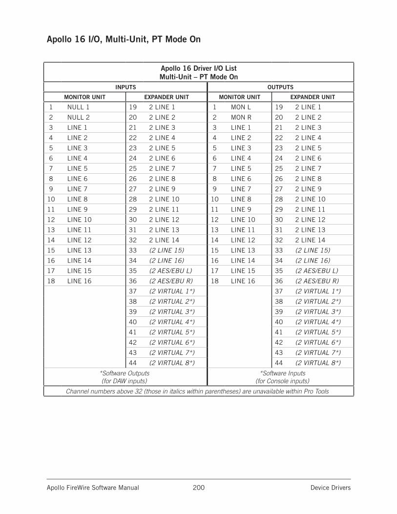
Apollo FireWire Software Manual Device Drivers 200
Apollo 16 I/O, Multi-Unit, PT Mode On
Apollo 16 Driver I/O List Multi-Unit – PT Mode On
INPUTS OUTPUTS
MONITOR UNIT EXPANDER UNIT MONITOR UNIT EXPANDER UNIT
1 NULL 1 19 2 LINE 1 1 MON L 19 2 LINE 1
2 NULL 2 20 2 LINE 2 2 MON R 20 2 LINE 2
3 LINE 1 21 2 LINE 3 3 LINE 1 21 2 LINE 3
4 LINE 2 22 2 LINE 4 4 LINE 2 22 2 LINE 4
5 LINE 3 23 2 LINE 5 5 LINE 3 23 2 LINE 5
6 LINE 4 24 2 LINE 6 6 LINE 4 24 2 LINE 6
7 LINE 5 25 2 LINE 7 7 LINE 5 25 2 LINE 7
8 LINE 6 26 2 LINE 8 8 LINE 6 26 2 LINE 8
9 LINE 7 27 2 LINE 9 9 LINE 7 27 2 LINE 9
10 LINE 8 28 2 LINE 10 10 LINE 8 28 2 LINE 10
11 LINE 9 29 2 LINE 11 11 LINE 9 29 2 LINE 11
12 LINE 10 30 2 LINE 12 12 LINE 10 30 2 LINE 12
13 LINE 11 31 2 LINE 13 13 LINE 11 31 2 LINE 13
14 LINE 12 32 2 LINE 14 14 LINE 12 32 2 LINE 14
15 LINE 13 33 (2 LINE 15) 15 LINE 13 33 (2 LINE 15)
16 LINE 14 34 (2 LINE 16) 16 LINE 14 34 (2 LINE 16)
17 LINE 15 35 (2 AES/EBU L) 17 LINE 15 35 (2 AES/EBU L)
18 LINE 16 36 (2 AES/EBU R) 18 LINE 16 36 (2 AES/EBU R)
37 (2 VIRTUAL 1*) 37 (2 VIRTUAL 1*)
38 (2 VIRTUAL 2*) 38 (2 VIRTUAL 2*)
39 (2 VIRTUAL 3*) 39 (2 VIRTUAL 3*)
40 (2 VIRTUAL 4*) 40 (2 VIRTUAL 4*)
41 (2 VIRTUAL 5*) 41 (2 VIRTUAL 5*)
42 (2 VIRTUAL 6*) 42 (2 VIRTUAL 6*)
43 (2 VIRTUAL 7*) 43 (2 VIRTUAL 7*)
44 (2 VIRTUAL 8*) 44 (2 VIRTUAL 8*)
*Software Outputs (for DAW inputs)
*Software Inputs (for Console inputs)
Channel numbers above 32 (those in italics within parentheses) are unavailable within Pro Tools
Apollo FireWire Software Manual Glossary 201
Glossary
A/D An acronym for “Analog to Digital,” which refers to the conversion of analog signals to digital data.
Acronym A word formed from the first letters of other words (e.g., GUI, ADAT, TRS, etc.).
ADAT An acronym for “Alesis Digital Audio Tape.” ADAT was the name given to the Alesis-branded products of the 1990s which recorded eight tracks of digital audio on a standard S-VHS video cassette. The term now generally refers to the 8-channel optical “Lightpipe” connection that is used in a wide range of digital products from many manu-facturers.
AES (sometimes written as “AES/EBU“) The name of a digital audio transfer standard jointly developed by the American-based Audio Engineering Society and the European Broadcast Union. Designed to carry two channels of 16-, 20- or, 24-bit digital audio at sampling rates of up to 192kHz, the most common AES physical interconnect utilizes a 3-conductor 110 ohm twisted pair cable, terminating at standard XLR connectors. (See “Dual Wire” and “Single Wire”)
Analog Literally, an analog is a replica or representation of something. In audio signals, changes in voltage are used to represent changes in acoustic sound pressure. Note that analog audio is a continuous representation, as opposed to the quantized, or discrete “stepped” representation created by digital devices. (See “Digital”)
API Acronym for Application Programming Interface. A software layer between an operat-ing system and third-party hardware (such as an audio interface) and/or software (such as a DAW). For example, a computer OS’s audio API enables audio hardware and audio software from different vendors to communicate with the OS and each other.
Apollo Expanded Universal Audio’s name for connecting more than one Apollo device together via Thunderbolt in a multi-unit cascading setup for increased I/O.
ASIO Acronym for Audio Stream Input/Output. ASIO is an audio interface driver protocol for Windows operating systems developed by Steinberg GmbH.
Balanced Audio cabling that uses two twisted conductors enclosed in a single shield, thus allowing relatively long cable runs with minimal signal loss and reduced induced noise such as hum.
Bit A contraction of the words “binary” and “digit,” a bit is a number used in a digi-tal system, and it can have only one of two values: 0 or 1. The number of bits in each sample determines the theoretical maximum dynamic range of the audio data, regardless of sample rate being used. Each additional bit adds approximately 6 dB to the dynamic range of the audio. In addition, the use of more bits helps capture quieter signal more accurately. (See “Sample” and “Dynamic range”)
Apollo FireWire Software Manual Glossary 202
Bit Depth (See “Bit Resolution”)
Bit Resolution Often used interchangeably with “bit depth,” this is a term used to de-scribe the number of bits used in a digital recording. Apollo converts analog audio and transmits digital audio with a resolution of 24 bits (thus yielding a theoretical dynamic range of approximately 145 dB), the highest audio interface resolution in common use today. (See “Dynamic Range”)
BNC A bayonet-type coaxial connector often found on video and digital audio equipment, as well as on test devices like oscilloscopes. In digital audio equipment, BNC connec-tors are normally used to carry word clock signals between devices. BNC connectors are named for their type (Bayonet), and their inventors, Paul Neil and Carl Concelman. (See “Word Clock”)
Buffer, buffers, buffering The transference of data in small batches instead of continu-ously. Buffering induces latency (delay) and is inherent in most digital audio systems.
Bus A signal path that carries more than one signal, e.g., a mix bus, auxiliary bus, head-phone cue bus, etc.
Channel Input Strip A group of controls that pertain only to the functions contained within a particular mixer input channel. In most mixing consoles, the “strips” are dupli-cated for each input.
Class A One design technique used in electronic devices such that their active compo-nents are drawing current and working throughout the full signal cycle, thus yielding a more linear response. This increased linearity results in fewer harmonics generated, hence lower distortion in the output signal.
Condenser Microphone A microphone design that utilizes an electrically charged thin conductive diaphragm stretched close to a metal disk called a backplate. Incoming sound pressure causes the diaphragm to vibrate, in turn causing the capacitance to vary in a like manner, which causes a variance in its output voltage. Condenser microphones tend to have excellent transient response but require an external voltage source, most often in the form of 48 volts of “phantom power.”
Clock In digital audio or video, a clock serves as a timing reference for a system. Every digital device must carry out specified numbers of operations per period of time and at a consistent speed in order for the device to work properly. Digital audio devices such as Apollo normally have an internal clock, and are also capable of locking to external clock routed from other digital devices. In order to avoid signal degradation or undesirable audible artifacts, it is absolutely critical that all digital devices that are interconnected in a system be locked to the same clock.
Clock Distribution Refers to the process of routing a master clock signal (either from an internal clock or an external source) to multiple devices by means of multiple outputs, thus removing the need to cascade the clock through external devices, which can de-grade the signal.
Core Audio The audio API for macOS.
Apollo FireWire Software Manual Glossary 203
D/A Acronym for “Digital to Analog,” which refers to the conversion of a digital data to an analog signal.
DAW Acronym for “Digital Audio Workstation” – that is, any device that can record, play back, edit, and process digital audio.
dB Abbreviation for “decibel,” a logarithmic unit of measure used to determine, among other things, power ratios, voltage gain, and sound pressure levels.
dBm Abbreviation for “decibels as referenced to milliwatt,” dissipated in a standard load of 600 ohms. 1 dBm into 600 ohms results in 0.775 volts RMS.
dBV Abbreviation for “decibels as referenced to voltage,” without regard for impedance; thus, one volt equals one dBV.
DI Acronym for “Direct Inject” or “Direct Input,” a recording technique whereby the signal from a high-impedance instrument such as electric guitar or bass is routed to an input. DI into mixer or tape recorder inputs often employ use of a “DI box,” which raises the signal to the correct voltage level at the right impedance.
Digital Information or data that is stored or communicated as a series of bits (binary digits, with values of 0 or 1). Digital audio refers to the representation of varying sound pressure levels by means of a series of numbers. (See “Analog” and “Bit”)
Dither Minute amounts of shaped noise added intentionally to a digital recording in order to reduce a form of distortion known as “quantization noise” and aid in low level sound resolution.
Dry Refers to a signal that is unprocessed, e.g., recording a dry signal. The antonym of a “wet” signal.
DSP Acronym for “Digital Signal Processing” (or “Digital Signal Processor.”)
DSP Accelerator A device dedicated to digital signal processing. UAD-2 devices are DSP accelerators.
Dynamic Microphone A type of microphone that generates signal with the use of a very thin, light diaphragm which moves in response to sound pressure. That motion in turn causes a voice coil which is suspended in a magnetic field to move, generating a small electric current. Dynamic mics are generally less expensive than condenser or ribbon mics and do not require external power to operate.
Dynamic Range The difference between the loudest sections of a piece of music and the softest ones. The dynamic range of human hearing (that is, the difference between the very softest passages we can discern and the very loudest ones we can tolerate) is con-sidered to be approximately 120 dB. (See “Bit resolution”)
EQ Abbreviation for “Equalization,” a circuit that allows selected frequency areas in an audio signal to be attenuated or boosted.
External Clock A clock signal derived from an external source. (See “Clock”)
FET Acronym for “Field Effect Transistor.” A type of transistor that relies on an electric field to control the shape, and hence the conductivity, of a “channel” in a semiconductor material.
Apollo FireWire Software Manual Glossary 204
Firmware Software that is embedded in hardware.
Flex Routing Apollo technology that enables its physical inputs to be routed to various physical outputs. Compare to Virtual I/O.
FPGA Acronym for “Field Programmable Gate Array.” A type of integrated circuit that can be programmed after manufacturing (“in the field”) to perform specialized functions.
Front End Refers to a device that provides analog and digital input/output (I/O) to a digi-tal audio workstation (DAW). Apollo is a front end.
Graphical User Interface A software window, panel, or screen containing controls where parameters are adjusted by the user. (See “GUI”)
GUI Acronym for Graphical User Interface.
Hi-Z Abbreviation for “High Impedance.” Apollo’s Hi-Z input allows direct connection of an instrument such as electric guitar or bass via a standard unbalanced ¼” jack.
High Resolution In digital audio, refers to 24-bit signals at sampling rates of 88.2 kHz or higher.
Hz Abbreviation for “Hertz,” a unit of measurement describing a single analog audio cycle (or digital sample) per second.
Impedance A description of a circuit’s resistance to a signal, as measured in ohms, thou-sands of ohms (Kilohms), or millions of ohms (megohms).
Internal Clock A clock signal derived from onboard circuitry. (See “Clock”)
I/O Acronym for “input/output.”
kHz Abbreviation for “kiloHertz” (a thousand Hertz), a unit of measurement describing a thousand analog audio cycles (or digital samples) per second. (See “Hz”)
JFET Acronym for Junction Field Effect Transistor, a specific type of FET which has some similarities to traditional bipolar transistor designs that can make it more appropriate for use in some audio circuit designs. (See “FET”)
Jitter Refers to short-term variations in the edges of a clock signal, caused by a bad source clock, inferior cabling or improper cable termination, and/or signal-induced noise. A jittery signal will contain spurious tones at random, inharmonic frequencies. Usu-ally, the jitter will be worse with higher signal frequencies. The internal digital clock of Apollo was designed for extreme stability and jitter-free operation, and its onboard phase aligned clock conditioner circuitry removes jitter from external sources, so conversion quality is uneffected by clock source.
Lightpipe A digital connection made with optical cable. This was a phrase coined by Ale-sis to make a distinction between the proprietary 8-channel optical network used in their ADAT products and standard stereo optical connectors used on CD players and other consumer products.
Apollo FireWire Software Manual Glossary 205
Line Level Refers to the voltages used by audio devices such as mixers, signal proces-sors, tape recorders, and DAWs. Professional audio systems typically utilize line level signals of +4 dBm (which translates to 1.23 volts), while consumer and semiprofessional audio equipment typically utilize line level signals of -10 dBV (which translates to 0.316 volts).
Low Cut Filter An equalizer circuit that cuts signal below a particular frequency. Same as “high pass filter.”
Mic Level Refers to the very low level signal output from microphones, typically around 2 millivolts (2 thousandths of a volt).
Mic Preamp The output level of microphones is very low and therefore requires specially designed mic preamplifiers to raise (amplify) their level to that needed by a mixing con-sole, tape recorder, or digital audio workstation (DAW).
Mute “Turn off the signal.” Mute stops the signal from being routed.
Native Refers to computer-based digital audio recording software controlled by the com-puter’s onboard processor, as opposed to software that requires external hardware to run.
OS Acronym for Operating System. The OS is the software used to control the computer hardware, such as macOS (Mac) and Windows (PC).
Pan Abbreviation for “Panorama” or “Panoramic.” A pan control determines a mono-phonic signal’s positioning in the stereo field.
Patch Bay A passive, central routing station for audio signals. In most recording studios, the line-level inputs and outputs of all devices are connected to a patch bay, making it an easy matter to re-route signal with the use of patch cords.
Patch Cord A short audio cable with connectors on each end, typically used to intercon-nect components wired to a patch bay.
PDF Acronym for “Portable Document Format.” PDF is the standardized file format used for distribution of documentation in electronic form. Various applications can open PDF files; one such “reader” application is available for free at www.adobe.com.
Plug-In Software components that are added to host software applications to enhance their functionality and/or performance.
Powered Plug-Ins High-quality audio processing plug-ins, developed and sold by Univer-sal Audio, that run exclusively on UAD DSP accelerator products.
Quantization Noise A form of digital distortion caused by mathematical rounding-off er-rors in the analog to digital conversion process. Quantization noise can be reduced dra-matically by dithering the digital signal. (See “Dither“)
Apollo FireWire Software Manual Glossary 206
Realtime UAD Processing Universal Audio’s DSP + FPGA technology that enables UAD Powered Plug-Ins to run with latencies in the sub-2ms range. Realtime UAD processing provides the ultimate sonic experience while monitoring and/or tracking. Realtime UAD processing is a special function that is available only within the Console application.
Ribbon Microphone A type of microphone that works by loosely suspending a small ele-ment (usually a corrugated strip of metal) in a strong magnetic field. This “ribbon” is moved by the motion of air molecules and in doing so it cuts across the magnetic lines of flux, causing an electrical signal to be generated. Ribbon microphones tend to be deli-cate and somewhat expensive, but often have very flat frequency response.
Sample A digital “snapshot” of the amplitude of a sound at a single instant in time. The number of samples taken per second is determined by the device’s sample rate. (See “Sample rate”)
Sample Rate The number of samples per second. In digital audio, there are six com-monly used sample rates: 44.1 kHz (used by audio CDs), 48 kHz, 88.2 kHz (2 x 44.1 kHz), 96 kHz (2 x 48 kHz, used by DVDs), 176.4 kHz (4 x 44.1 kHz), and 192 kHz (4 x 48 kHz). The higher the sample rate, the greater the frequency response of the resulting signal; however, higher sample rates require more storage space. (See “kHz”)
Sample Rate Conversion The process of altering a digital signal’s sample rate to a differ-ent sample rate.
S/MUX (sometimes written as “S-MUX”) Abbreviation for Sample Multiplexing. S/MUX is a method for transmitting two channels of high sample rate (88.2, 96, 176.4, or 192 kHz) 24-bit digital audio over a legacy optical “lightpipe” ADAT connection, which was originally designed to carry eight channels of 16-, 20- or 24-bit audio at 44.1 kHz or 48 kHz sampling rate. (See “ADAT” and “Lightpipe”)
SPDIF (sometimes written as “S/PDIF”) An acronym for “Sony/Philips Digital Interface Format,” a digital audio transfer standard largely based on the AES/EBU standard. De-signed to carry two channels of 16-, 20- or, 24-bit digital audio at sampling rates of up to 192 kHz, the most common SPDIF physical interconnect utilizes unbalanced, 75 ohm video-type coaxial cables terminating at phono (RCA-type) connectors. (See “AES”)
Superclock A proprietary format used by some early Pro Tools systems to distribute clock signal running at 256x the system’s sample rate, thus matching the internal timing reso-lution of the software. (See “Clock” and “Pro Tools”)
Transcoding Converting one type of digital signal to another (i.e, from AES to SPDIF, or from ADAT to AES).
Transformer An electronic component consisting of two or more coils of wire wound on a common core of magnetically permeable material. Audio transformers operate on audible signal and are designed to step voltages up and down and to send signal between micro-phones and line-level devices such as mixing consoles, recorders, and DAWs.
Transient A relatively high volume pitchless sound impulse of extremely brief duration, such as a pop. Consonants in singing and speech, and the attacks of musical instru-ments (particularly percussive instruments), are examples of transients.
Apollo FireWire Software Manual Glossary 207
Transimpedance Preamplifier A transformerless solid-state preamplifier utilizing a tran-sistor configuration that employs current feedback for ultra-low distortion and the highest possible quality of signal from input to output. The transimpedance design allows audio from 4 Hz to 150 kHz to pass through without altering the phase relationships between fundamental frequencies and overtones. Noise and distortion are kept to near-theoretical minimums so critical signals may be generously amplified without degrading the quality or character of the sound source.
TRS Acronym for Tip-Ring-Sleeve. A ¼” phone connector with three conductors, typically used for balanced signal connections (e.g., I/O) or carrying two unbalanced signals (e.g., headphones).
TS Acronym for Tip-Sleeve. A ¼” phone connector with two conductors, typically used for unbalanced signal connections. Note that TS, like TRS and XLR, denotes the con-nector only and does not necessarily indicate the signal level of the connection. TS/TRS/XLR cables are used for both low-level (e.g., microphones and instruments) and line-level connections.
UAD Acronym for “Universal Audio Digital.” Used in reference to digital products created by Universal Audio.
UAD-2 A line of DSP accelerator products developed and manufactured by Universal Audio.
Unison Universal Audio’s exclusive preamp hardware/software integration technology that enables UAD preamp plug-ins reconfigure the physical input impedance, gain staging response, and other parameters of Apollo’s mic preamp hardware to match the emulated preamp’s hardware design characteristics with bi-direction control.
Virtual I/O Apollo audio inputs and outputs that exist in software but not in hardware. Vir-tual I/O is used to route digital audio channels between Console and other audio applica-tions. Compare to Flex Routing.
Wet Refers to a signal that is processed, e.g., recording a wet signal. The antonym of a “dry” signal.
Word Clock A dedicated clock signal based on the transmitting device’s sample rate or the speed with which sample words are sent over a digital connection. (See “Clock”)
XLR A standard three-pin connector used by many audio devices, with pin 1 typically connected to the shield of the cabling, thus providing ground. Pins 2 and 3 are used to carry audio signal, normally in a balanced (out of phase) configuration.
Apollo FireWire Software Manual Notices 208
Notices
DisclaimerThe information contained in this manual is subject to change without notice. Univer-sal Audio, Inc. makes no warranties of any kind with regard to this manual, including, but not limited to, the implied warranties of merchantability and fitness for a particular purpose. Universal Audio, Inc. shall not be liable for errors contained herein or direct, indirect, special, incidental, or consequential damages in connection with the furnishing, performance, or use of this material.
End User License AgreementYour rights to the Software are governed by the accompanying End User License Agree-ment, a copy of which can be found at: www.uaudio.com/eula
TrademarksUniversal Audio, the Universal Audio “diamond” logo, Apollo, Apollo Twin, Apollo 16, Unison technology, UAD, UAD Series, UAD-1, UAD-2, UAD-2 Satellite, Powered Plug-Ins, 1176LN, 1176SE, Teletronix, LA-2A, LA-3A, LA-610, LA-610MkII, 2-1176, 2-610, 6176, 710 Twin-Finity, 2192, 4-710d, Cambridge EQ, DreamVerb, Plate 140, Precision Limiter, RealVerb Pro, Precision Buss Compressor, Precision De-Esser, Precision Maxi-mizer, and “Analog Ears | Digital Minds,” are among the trademarks, trade names, and service marks owned by UA that may appear on the Site, many of which are registered in the United States and other countries. This is not a comprehensive list of all UA trade-marks. All UA trademarks inure to the benefit of UA. Other trademarks and trade names that may appear on the Site and which are not owned by UA are owned by the respective owners.
CopyrightCopyright ©2019 Universal Audio, Inc. All rights reserved.
This manual and any associated software, artwork, product designs, and design concepts are subject to copyright protection. No part of this document may be reproduced, in any form, without prior written permission of Universal Audio, Inc.

Universal Audio Technical Support209
Technical Support
Universal Audio Knowledge BaseThe UA Knowledge Base is your complete online technical resource for configuring, operating, troubleshooting, and repairing all UA products.
You can watch helpful support videos, search the Knowledge Base for answers, get updated technical information that may not be available elsewhere, and more.
UA Knowledge Base
YouTube Support ChannelThe Universal Audio Support Channel at youtube.com includes helpful support videos for setting up and using UA products.
UA YouTube Support Channel
Universal Audio Community ForumsThe unofficial UA discussion forums are a valuable resource for all Universal Audio product users. This website is independently owned and operated.
www.uadforum.com
Contact Universal Audio SupportTo contact the UA support team for technical or repair assistance, please visit:
help.uaudio.com