Embed Size (px)
Citation preview
APlocate: Location and Weather User Guide
IES Virtual Environment
Copyright © 2015 Integrated Environmental Solutions Limited. All rights reserved.
No part of the manual is to be copied or reproduced in any form without the express agreement of Integrated Environmental Solutions Limited.
VE 2015
APlocate: Location and Weather 2
Contents
1 INTRODUCTION 3
2 APLOCATE TABS 4
2.1 Tab: Location & Site Data 4
2.2 Tab: Design Weather Data 7
2.3 Tab: Simulation Weather Data 12
2.4 Tab: Simulation Calendar 14
3 WEATHER SELECTION WIZARD 17
3.1 Page 1: Location Data 17
3.2 Pages 2-3: Source of Design Weather 19
3.3 Page 4: Simulation Weather File 25
4 SUNPATH 27
4.1 Purpose 27
5 APLOCATE MENUS 28
5.1 File Menu 28
5.2 Options Menu 28
5.3 Help Menu 28
5.4 Toolbar Buttons 28
VE 2015
APlocate: Location and Weather 3
1 Introduction ApLocate is the weather and site location editor for these programs:
CIBSE Heat Loss & Heat Gains (ApacheCalc)
ASHRAE Heat Balance Method (ApacheLoads)
ApacheSim
SunCast
Radiance
It is possible to choose a location from an extensive database and guidance is given on defining weather data for various locations.
Normally ApLocate is called from within the <Virtual Environment> by clicking the ApLocate icon. Default site and weather data will be set up when a new model is started. To edit these defaults, create new data or change location you must use ApLocate. It is advisable to edit project specific data as soon as the information becomes available. If you begin using the <Virtual Environment> when project data is unknown you may create it at a later date.
There are four tabs on the ApLocate dialog:
Location & Site Data
Design Weather Data
Simulation Weather Data
Simulation Calendar
ApLocate also has a selection wizard that assists the user in populating the first three tabs.
VE 2015
APlocate: Location and Weather 4
2 ApLocate Tabs
2.1 Tab: Location & Site Data
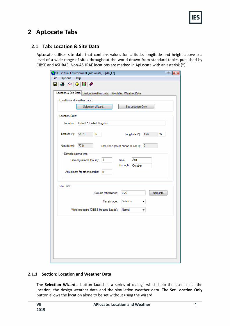
ApLocate utilises site data that contains values for latitude, longitude and height above sea level of a wide range of sites throughout the world drawn from standard tables published by CIBSE and ASHRAE. Non-ASHRAE locations are marked in ApLocate with an asterisk (*).
2.1.1 Section: Location and Weather Data
The Selection Wizard… button launches a series of dialogs which help the user select the location, the design weather data and the simulation weather data. The Set Location Only button allows the location alone to be set without using the wizard.
VE 2015
APlocate: Location and Weather 5
2.1.2 Section: Location Data
The information in this section is not editable by the user. Whenever a new location is selected by either of the two buttons above, this section is automatically updated.
2.1.2.1 Location Data: Latitude
The Latitude within ApLocate is expressed as decimal degrees North or South. In other words, 20º 30” N appears as 20.50 with the drop-down box beside the number set to N.
2.1.2.2 Location Data: Altitude
The height above sea level of the building. For locations below sea level, negative values are appropriate. The data is used in the calculation of solar gains and atmospheric pressure in Heat Gain. In System Simulation the solar gains and atmospheric pressure are read in directly from the weather file and so this data is not used.
2.1.2.3 Location data: Longitude
The Longitude within ApLocate is expressed as decimal degrees East or West. In other words, 20º 30” E appears as 20.50 with the drop-down box beside the number set to E. The longitude is regarded as increasing westwards from Greenwich, so 20º East of Greenwich is rendered as 340º.
2.1.2.4 Daylight Saving Time: Time Adjustment
The local time correction applicable for Daylight saving time during the months From to Through inclusive. The value is approximated to the nearest hour. Positive is in advance of sun time.
2.1.2.5 Daylight Saving Time: Daylight Saving Period
These are the two months within which the local time correction firstly starts to apply, and secondly no longer applies.
Note that in Northern latitudes, the Through month will normally be later than the From month and in Southern latitudes it will be earlier.
2.1.2.6 Daylight Saving Time: Adjustment for Other Months
‘Other Months’ are those months not included in the From - Through period. For example, if the From month were April and the Through month October (the default condition), then this time correction would apply to November to March inclusive.
2.1.3 Section: Site Data
The information in this section is editable by the user.
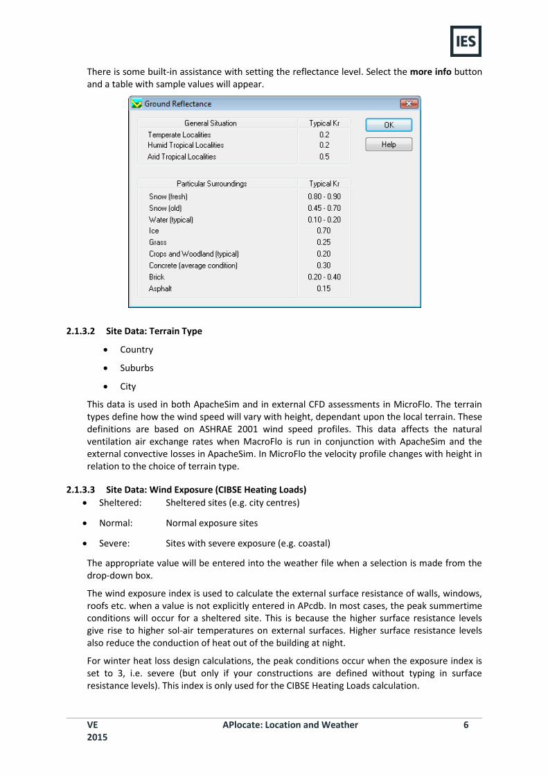
2.1.3.1 Site Data: Ground Reflectance
This is a measure of the ground albedo (Kr). Typical values are listed below, or in CIBSE Guide A2, Table A2.31. It is used in APcalc and ApacheSim for the calculation of ground reflected radiation on building facades.
VE 2015
APlocate: Location and Weather 6
There is some built-in assistance with setting the reflectance level. Select the more info button and a table with sample values will appear.
2.1.3.2 Site Data: Terrain Type
Country
Suburbs
City
This data is used in both ApacheSim and in external CFD assessments in MicroFlo. The terrain types define how the wind speed will vary with height, dependant upon the local terrain. These definitions are based on ASHRAE 2001 wind speed profiles. This data affects the natural ventilation air exchange rates when MacroFlo is run in conjunction with ApacheSim and the external convective losses in ApacheSim. In MicroFlo the velocity profile changes with height in relation to the choice of terrain type.
2.1.3.3 Site Data: Wind Exposure (CIBSE Heating Loads)
Sheltered: Sheltered sites (e.g. city centres)
Normal: Normal exposure sites
Severe: Sites with severe exposure (e.g. coastal)
The appropriate value will be entered into the weather file when a selection is made from the drop-down box.
The wind exposure index is used to calculate the external surface resistance of walls, windows, roofs etc. when a value is not explicitly entered in APcdb. In most cases, the peak summertime conditions will occur for a sheltered site. This is because the higher surface resistance levels give rise to higher sol-air temperatures on external surfaces. Higher surface resistance levels also reduce the conduction of heat out of the building at night.
For winter heat loss design calculations, the peak conditions occur when the exposure index is set to 3, i.e. severe (but only if your constructions are defined without typing in surface resistance levels). This index is only used for the CIBSE Heating Loads calculation.
VE 2015
APlocate: Location and Weather 7
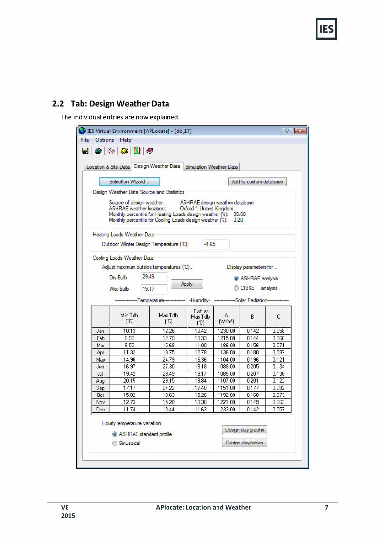
2.2 Tab: Design Weather Data
The individual entries are now explained.
VE 2015
APlocate: Location and Weather 8
2.2.1 Section: Design Weather Data Source and Statistics
This section of the dialog contains the information about how the weather data has been chosen using the Selection Wizard. The Selection Wizard… button will take the user directly to the design weather data section (Pages 2-3) of the wizard if selected here. The Add to custom database button allows the user to save the current design weather data.
2.2.2 Section: Heating Loads Weather Data
2.2.2.1 Outdoor Winter Design Temperature
This is the outside air dry-bulb design temperature applicable to the building location. This number is only used in ApacheLoads and ApacheCalc calculations. This value can be either manually entered or derived by the Weather Selection Wizard.
2.2.3 Section: Cooling Loads Weather Data
Cooling loads weather data describes the summer time external design weather data. This data is used for both CIBSE and ASHRAE cooling loads calculations. The different parameters that are used for both types of analysis can be viewed by selecting either the ASHRAE analysis or CIBSE analysis radio button.
VE 2015
APlocate: Location and Weather 9
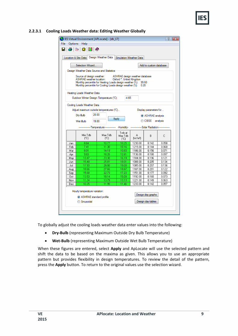
2.2.3.1 Cooling Loads Weather data: Editing Weather Globally
To globally adjust the cooling loads weather data enter values into the following:
Dry-Bulb (representing Maximum Outside Dry Bulb Temperature)
Wet-Bulb (representing Maximum Outside Wet Bulb Temperature)
When these figures are entered, select Apply and ApLocate will use the selected pattern and shift the data to be based on the maxima as given. This allows you to use an appropriate pattern but provides flexibility in design temperatures. To review the detail of the pattern, press the Apply button. To return to the original values use the selection wizard.
VE 2015
APlocate: Location and Weather 10
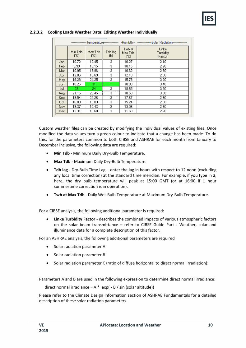
2.2.3.2 Cooling Loads Weather Data: Editing Weather Individually
Custom weather files can be created by modifying the individual values of existing files. Once modified the data values turn a green colour to indicate that a change has been made. To do this, for the parameters common to both CIBSE and ASHRAE for each month from January to December inclusive, the following data are required:
Min Tdb - Minimum Daily Dry-Bulb Temperature.
Max Tdb - Maximum Daily Dry-Bulb Temperature.
Tdb lag - Dry-Bulb Time Lag – enter the lag in hours with respect to 12 noon (excluding any local time correction) at the standard time meridian. For example, if you type in 3, here, the dry bulb temperature will peak at 15:00 GMT (or at 16:00 if 1 hour summertime correction is in operation).
Twb at Max Tdb - Daily Wet-Bulb Temperature at Maximum Dry-Bulb Temperature.
For a CIBSE analysis, the following additional parameter is required:
Linke Turbidity Factor - describes the combined impacts of various atmospheric factors on the solar beam transmittance – refer to CIBSE Guide Part J Weather, solar and illuminance data for a complete description of this factor.
For an ASHRAE analysis, the following additional parameters are required
Solar radiation parameter A
Solar radiation parameter B
Solar radiation parameter C (ratio of diffuse horizontal to direct normal irradiation):
Parameters A and B are used in the following expression to determine direct normal irradiance:
direct normal irradiance = A * exp( - B / sin (solar altitude))
Please refer to the Climate Design Information section of ASHRAE Fundamentals for a detailed description of these solar radiation parameters.
VE 2015
APlocate: Location and Weather 11
This data must be entered for 12 months of the year (if you are only interested in summer conditions, leave the winter data in its default state). ApLocate uses this data to generate sinusoidally varying weather data for input to the CIBSE and ASHRAE Heat Gain calculations.
2.2.3.3 Cooling Loads Weather Data: Hourly Temperature Variation
The Sinusoidal and ASHRAE standard profile options dictate the way in which the daily cooling loads weather data is generated from the maxima and minima parameters. By choosing the Design Day Graphs or Design Day Tables the effect of either the sinusoidal (to be used in CIBSE Heat Gain calculation) or the ASHRAE standard profile (to be used in ASHRAE Heat Balance cooling load calculation) can be viewed. Either method can be used whether CIBSE or ASHRAE calculations are performed.
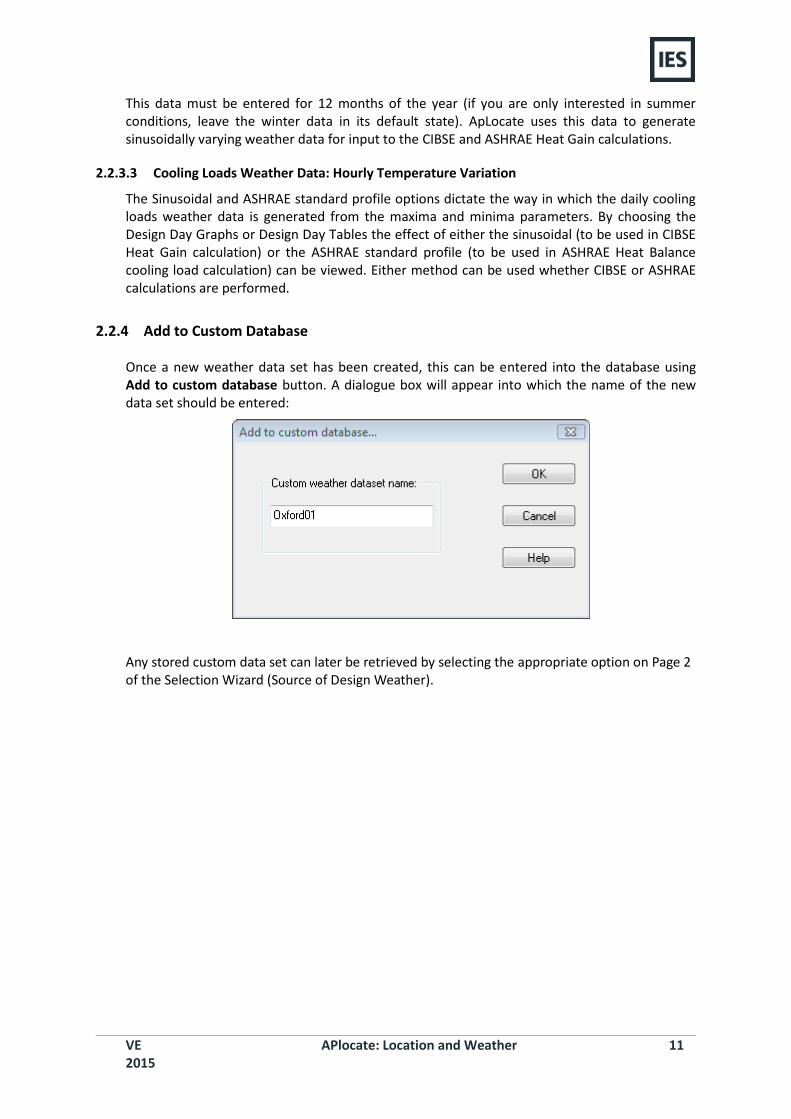
2.2.4 Add to Custom Database
Once a new weather data set has been created, this can be entered into the database using Add to custom database button. A dialogue box will appear into which the name of the new data set should be entered:
Any stored custom data set can later be retrieved by selecting the appropriate option on Page 2 of the Selection Wizard (Source of Design Weather).
VE 2015
APlocate: Location and Weather 12
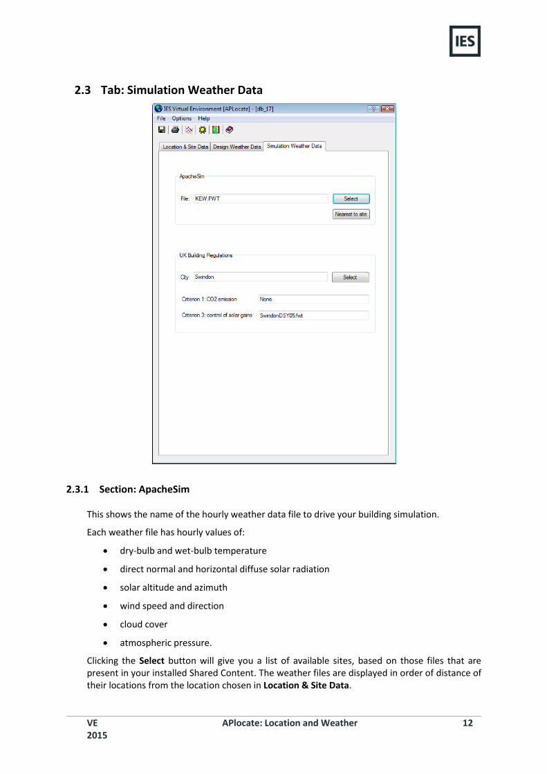
2.3 Tab: Simulation Weather Data
2.3.1 Section: ApacheSim
This shows the name of the hourly weather data file to drive your building simulation.
Each weather file has hourly values of:
dry-bulb and wet-bulb temperature
direct normal and horizontal diffuse solar radiation
solar altitude and azimuth
wind speed and direction
cloud cover
atmospheric pressure.
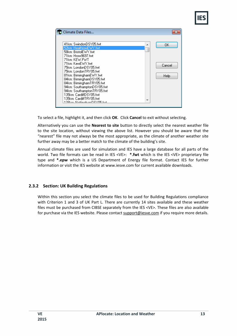
Clicking the Select button will give you a list of available sites, based on those files that are present in your installed Shared Content. The weather files are displayed in order of distance of their locations from the location chosen in Location & Site Data.
VE 2015
APlocate: Location and Weather 13
To select a file, highlight it, and then click OK. Click Cancel to exit without selecting.
Alternatively you can use the Nearest to site button to directly select the nearest weather file to the site location, without viewing the above list. However you should be aware that the “nearest” file may not always be the most appropriate, as the climate of another weather site further away may be a better match to the climate of the building’s site.
Annual climate files are used for simulation and IES have a large database for all parts of the world. Two file formats can be read in IES <VE>: *.fwt which is the IES <VE> proprietary file type and *.epw which is a US Department of Energy file format. Contact IES for further information or visit the IES website at www.iesve.com for current available downloads.
2.3.2 Section: UK Building Regulations
Within this section you select the climate files to be used for Building Regulations compliance with Criterion 1 and 3 of UK Part L. There are currently 14 sites available and these weather files must be purchased from CIBSE separately from the IES <VE>. These files are also available for purchase via the IES website. Please contact [email protected] if you require more details.
VE 2015
APlocate: Location and Weather 14
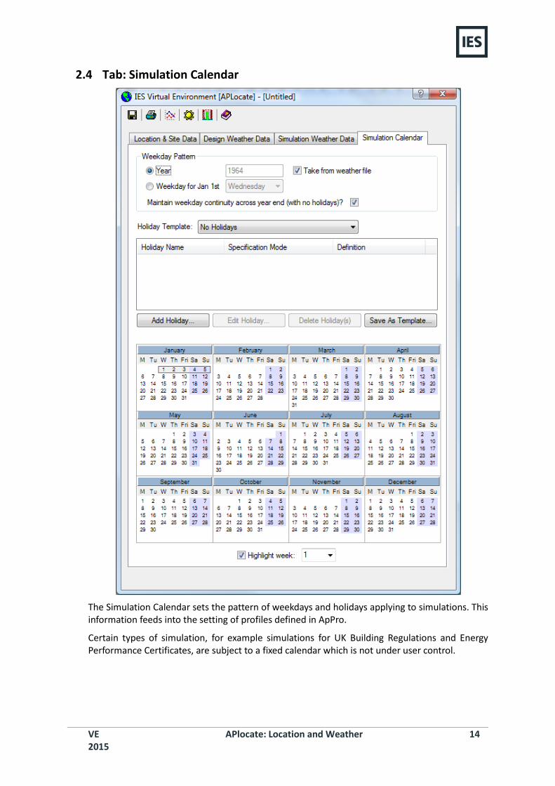
2.4 Tab: Simulation Calendar
The Simulation Calendar sets the pattern of weekdays and holidays applying to simulations. This information feeds into the setting of profiles defined in ApPro.
Certain types of simulation, for example simulations for UK Building Regulations and Energy Performance Certificates, are subject to a fixed calendar which is not under user control.
VE 2015
APlocate: Location and Weather 15
2.4.1 Section: Weekday Pattern
The pattern of weekdays used in simulation can be defined in two ways. You can set the year, in which case the weekday pattern will be deduced from the real-world calendar appropriate to that year, or alternatively you can set the weekday for January 1st.
If you use the ‘Year’ option, there is a further choice. If you tick ‘Take from weather file’ the year will be set from the year recorded on the simulation weather file. If you do not tick this box you can set the year explicitly. In either case ‘Weekday for Jan 1st’ will be set to the weekday on which January 1st fell (or will fall) in that year. Leap years are not catered for in the simulation, so in the case of a leap year there will be a mismatch between the simulated weekday and the real-world weekday from March 1st onwards.
Each of the options described above sets the weekday pattern for all days of the year. The weekdays are assumed to cycle round the sequence Monday, Tuesday, Wednesday... between January 1st and December 31st. Because the 365-day simulation year is 52 weeks and one day, December 31st and January 1st are assigned the same weekday, so the cyclic weekday pattern is broken at this point for simulations which cross the year end.
2.4.2 Section: Holidays
In ApPro, daily profiles may be assigned to the 7 days of the week plus a holiday day-type. The holiday day-type applies to days defined as holidays in the Simulation Calendar.
The simplest way to set a holiday pattern is by selecting a Holiday Template. Holiday Templates are available for many regions of the world. You can also create your own Holiday Templates.
Holidays appear in the list displayed in the centre of the dialog. A holiday is a single day of the year, and has the following user-editable attributes.
Holiday Name can be any suitable text string.
Specification Mode specifies how the holiday is defined. The options are:
Day/Month (fixed). Assigns the holiday to a specified day of a specified month – for example the 1st of January. If this day falls on a weekend or another holiday it is ignored.
Day/Month (or next weekday). Assigns the holiday to a specified day of a specified month, or, if this falls on a weekend or another holiday, to the next available weekday.
Day/Month (or nearest weekday). Assigns the holiday to a specified day of a specified month, or, if this falls on a weekend or another holiday, to the nearest available weekday.
Weekday/Week. Assigns the holiday to a specified weekday of a specified week – for example Wednesday in week 32.
Weekday/Month. Assigns the holiday to a specified weekday of a specified month – for example the fourth Thursday in November.
In each case, the details of the holiday are specified in the ‘Definition’ field.
‘Add Holiday’ adds a holiday to the list.
‘Edit Holiday’ edits the currently selected holiday. The data is edited in a pop-up dialog. Another way to edit an existing holiday is to double-click an entry in the holiday list.
‘Delete Holiday’ deletes the currently selected holiday.
‘Save As Template’ saves the current holiday list as a Holiday Template for use in other projects. You will be prompted to supply a suitable name for the Template.
VE 2015
APlocate: Location and Weather 16
The Simulation Calendar at the bottom of the dialog displays the currently set holidays with yellow markers.
‘Highlight Week’ allows you to identify a numbered week, as used by the ‘Weekday/Week’ Specification Mode. Enter the number of the week, which will then be displayed in the Calendar. Numbered weeks always run from Monday to Sunday, with Week 1 ending on the first Sunday in the year.
VE 2015
APlocate: Location and Weather 17
3 Weather Selection Wizard The Selection Wizard… button launches a series of dialogs which help the user select the location, the design weather data and the simulation weather data. The selection wizard allows the user access to choose the Location, the Design Weather, and the Simulation Weather dataset.
The selection wizard button appears on both the Location & Site Data tab and the Design Weather Data tab. If the wizard is chosen from the Location tab, the user can change the Location, the Design Weather, and the Simulation Weather dataset. If the selection wizard is chosen from the Design weather tab, the user can only manipulate the design weather data.
The individual pages of the wizard are now described.
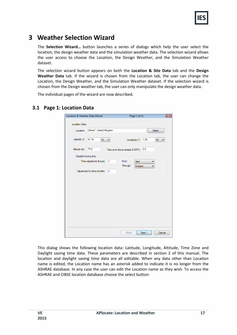
3.1 Page 1: Location Data
This dialog shows the following location data: Latitude, Longitude, Altitude, Time Zone and Daylight saving time data. These parameters are described in section 2 of this manual. The location and daylight saving time data are all editable. When any data other than Location name is edited, the Location name has an asterisk added to indicate it is no longer from the ASHRAE database. In any case the user can edit the Location name as they wish. To access the ASHRAE and CIBSE location database choose the select button:
VE 2015
APlocate: Location and Weather 18
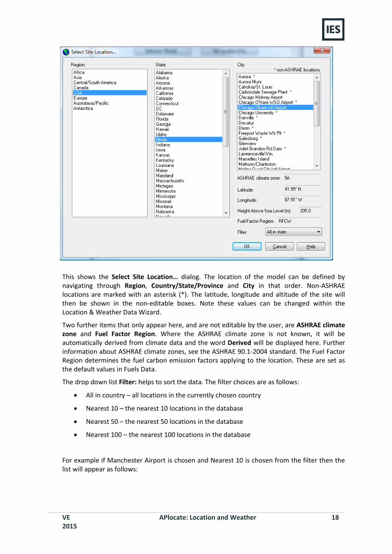
This shows the Select Site Location… dialog. The location of the model can be defined by navigating through Region, Country/State/Province and City in that order. Non-ASHRAE locations are marked with an asterisk (*). The latitude, longitude and altitude of the site will then be shown in the non-editable boxes. Note these values can be changed within the Location & Weather Data Wizard.
Two further items that only appear here, and are not editable by the user, are ASHRAE climate zone and Fuel Factor Region. Where the ASHRAE climate zone is not known, it will be automatically derived from climate data and the word Derived will be displayed here. Further information about ASHRAE climate zones, see the ASHRAE 90.1-2004 standard. The Fuel Factor Region determines the fuel carbon emission factors applying to the location. These are set as the default values in Fuels Data.
The drop down list Filter: helps to sort the data. The filter choices are as follows:
All in country – all locations in the currently chosen country
Nearest 10 – the nearest 10 locations in the database
Nearest 50 – the nearest 50 locations in the database
Nearest 100 – the nearest 100 locations in the database
For example if Manchester Airport is chosen and Nearest 10 is chosen from the filter then the list will appear as follows:
VE 2015
APlocate: Location and Weather 19
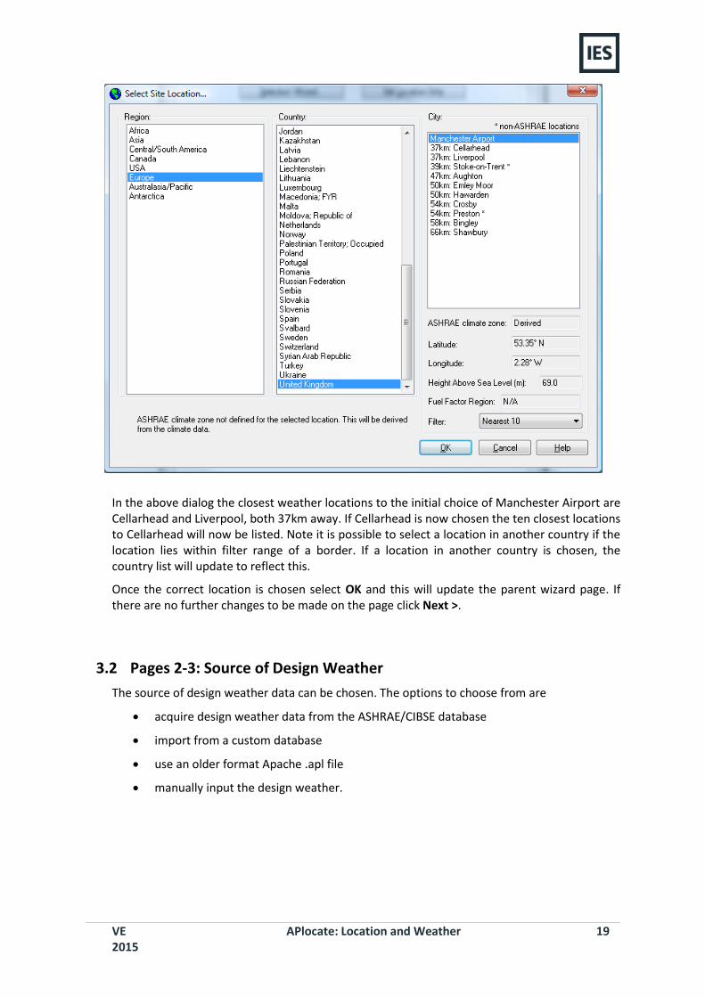
In the above dialog the closest weather locations to the initial choice of Manchester Airport are Cellarhead and Liverpool, both 37km away. If Cellarhead is now chosen the ten closest locations to Cellarhead will now be listed. Note it is possible to select a location in another country if the location lies within filter range of a border. If a location in another country is chosen, the country list will update to reflect this.
Once the correct location is chosen select OK and this will update the parent wizard page. If there are no further changes to be made on the page click Next >.
3.2 Pages 2-3: Source of Design Weather
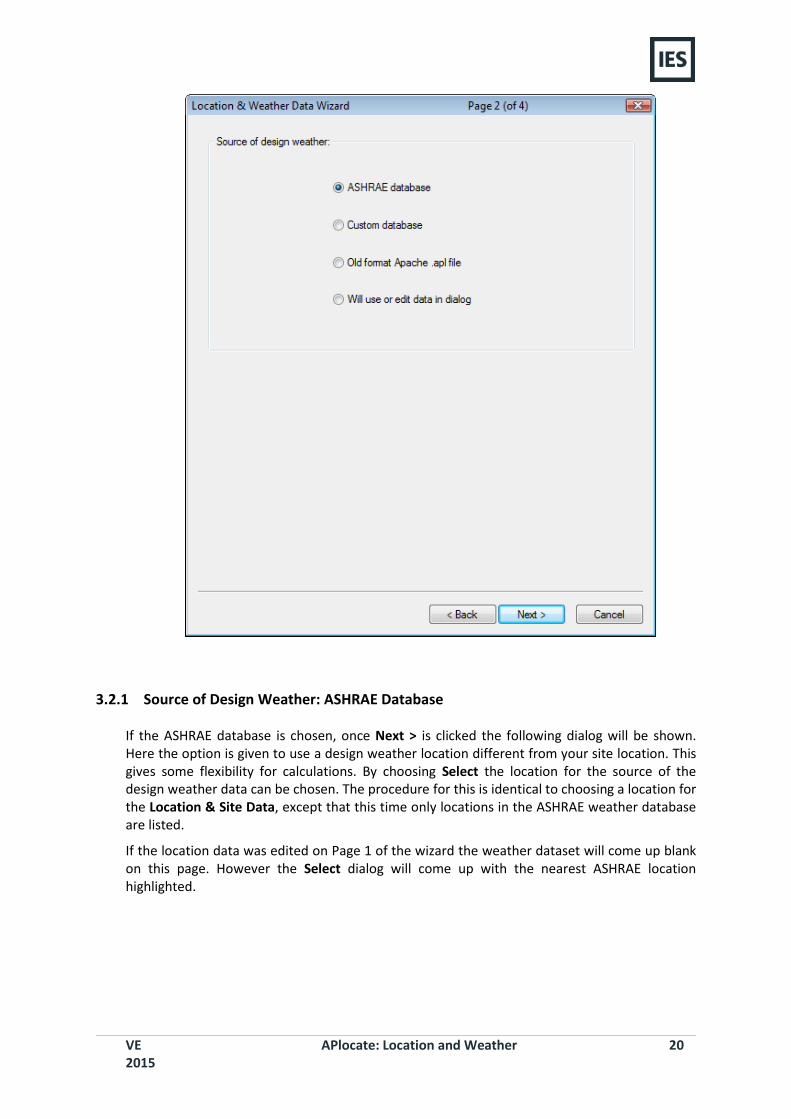
The source of design weather data can be chosen. The options to choose from are
acquire design weather data from the ASHRAE/CIBSE database
import from a custom database
use an older format Apache .apl file
manually input the design weather.
VE 2015
APlocate: Location and Weather 20
3.2.1 Source of Design Weather: ASHRAE Database
If the ASHRAE database is chosen, once Next > is clicked the following dialog will be shown. Here the option is given to use a design weather location different from your site location. This gives some flexibility for calculations. By choosing Select the location for the source of the design weather data can be chosen. The procedure for this is identical to choosing a location for the Location & Site Data, except that this time only locations in the ASHRAE weather database are listed.
If the location data was edited on Page 1 of the wizard the weather dataset will come up blank on this page. However the Select dialog will come up with the nearest ASHRAE location highlighted.

VE 2015
APlocate: Location and Weather 21
Once a location for the design weather dataset is chosen then the user has the choice to decide upon how the design summer and winter external temperature is derived.
To illustrate, a Percentile for Heating Loads weather of 99.6% defines an external winter weather design condition where the outside temperature is colder than the design value for 0.4 % of the time, and a Percentile for Cooling Loads weather of 0.2% defines an external summer weather design condition where the inside design temperature is exceeded for 0.2% of the time.
There are 2 options, Fundamental and Statistical.
3.2.1.1 ASHRAE Fundamental Design Weather data
This gives tabular weather data taken directly from the ASHRAE fundamentals. In the case of Cooling loads, only Monthly data is suitable for use with Apache.
The available percentiles are fixed as follows:
Heating Loads weather: 99.6% and 99.0%
Cooling Loads weather: 0.4%, 2%, 5% and 10%
VE 2015
APlocate: Location and Weather 22
3.2.1.2 Statistical calculation based on ASHRAE WDVIEW 4.0 data
The ASHRAE weather datasets allow these external design temperatures to be based upon a statistical treatment. This treatment analyses the weather dataset and returns the design external temperatures that are only exceeded by the percentage of the year or month that the user specifies.
The Outdoor winter design temperature is the hourly average temperature exceeded on the given percentage (Annual percentile for Heating Loads design weather) of occasions in the historical dataset. This dataset is stored as a set of binned temperature statistics. Linear interpolation is applied between consecutive bins.
The peak design dry bulb temperature for cooling load calculations is the hourly average temperature that is exceeded on the given percentage (Annual or Monthly percentile for Cooling Loads design weather) of occasions in the historical dataset. This peak temperature appears in the table as the maximum dry bulb temperature for the warmest month. The percentage of the time that this temperature is exceeded in the peak month is then calculated. This monthly percentile is then applied to the other months to derive the design maximum dry bulb temperatures for those months on the same statistical basis. Minimum dry bulb temperatures are then obtained for each month by subtracting from the maximum dry bulb temperature the daily temperature swing calculated for each month. In the case of the peak month the temperature swing is provided in the database. For the other months the swing is estimated by deriving the amplitude of the first Fourier component of the clear sky horizontal global solar radiation flux for the month in question and using this to scale the temperature swing recorded for the peak month.
The wet bulb temperature coinciding with the maximum dry bulb temperature (Twb at max Tdb) for each month is calculated as the mean wet bulb temperature coincident with the maximum dry bulb temperature, using the historical binned temperature data.
The peak dry bulb and wet bulb temperatures obtained by this method are in close agreement with those published in the ASHRAE Handbook of Fundamentals for the annual percentiles 0.4%, 1% and 2%.
The Handbook also publishes monthly dry bulb and mean coincident wet bulb temperatures for monthly percentiles 0.4%, 2%, 5% and 10%. There is no fixed relationship between monthly and annual percentiles in general, but for a given temperature the monthly percentile will be greater than the annual percentile (by a factor of about 12 for very low percentiles). The monthly percentile is displayed following retrieval of the design weather data, and a desired value for monthly percentile can be achieved by applying successive adjustments to the annual percentile.
For further information about ASHRAE weather data, see Chapter 14 of the ASHRAE Fundamentals 2009.
3.2.1.3 Acquire design weather
Once the percentiles have been set, click on Acquire design weather to generate design weather conditions. This data can later be viewed in the Design Weather Data tab.
Note that any edits to the location and/or the percentiles are only effective after an Acquire has been performed.
VE 2015
APlocate: Location and Weather 23
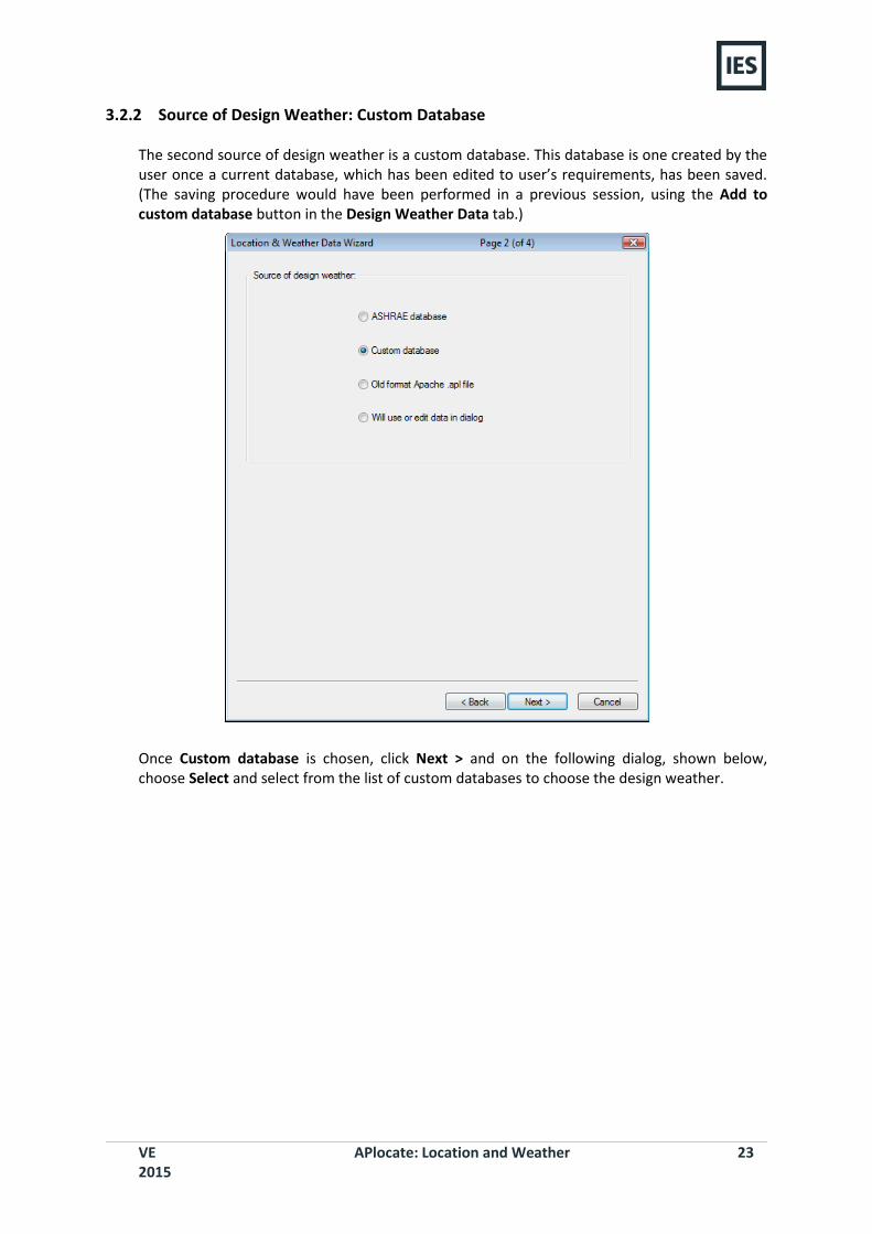
3.2.2 Source of Design Weather: Custom Database
The second source of design weather is a custom database. This database is one created by the user once a current database, which has been edited to user’s requirements, has been saved. (The saving procedure would have been performed in a previous session, using the Add to custom database button in the Design Weather Data tab.)
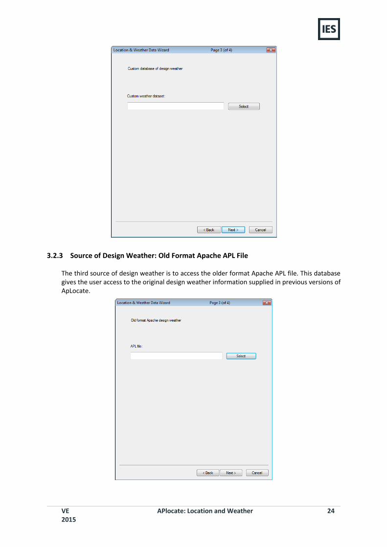
Once Custom database is chosen, click Next > and on the following dialog, shown below, choose Select and select from the list of custom databases to choose the design weather.
VE 2015
APlocate: Location and Weather 24
3.2.3 Source of Design Weather: Old Format Apache APL File
The third source of design weather is to access the older format Apache APL file. This database gives the user access to the original design weather information supplied in previous versions of ApLocate.
VE 2015
APlocate: Location and Weather 25
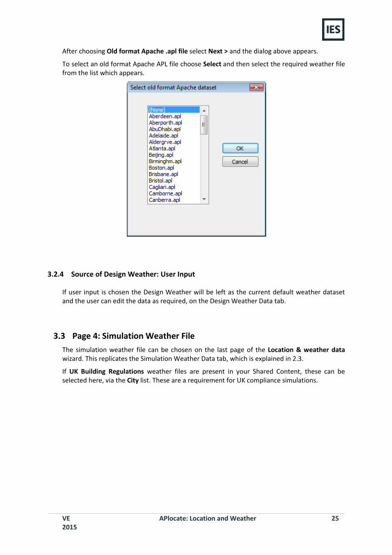
After choosing Old format Apache .apl file select Next > and the dialog above appears.
To select an old format Apache APL file choose Select and then select the required weather file from the list which appears.
3.2.4 Source of Design Weather: User Input
If user input is chosen the Design Weather will be left as the current default weather dataset and the user can edit the data as required, on the Design Weather Data tab.
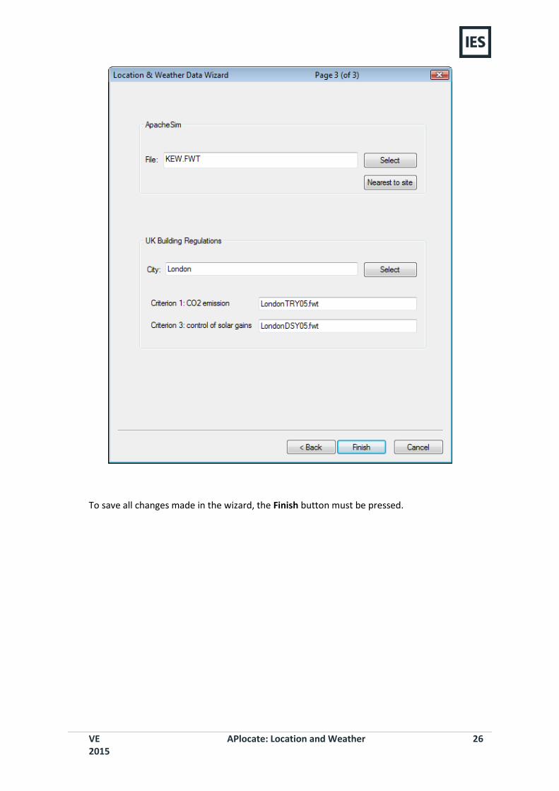
3.3 Page 4: Simulation Weather File
The simulation weather file can be chosen on the last page of the Location & weather data wizard. This replicates the Simulation Weather Data tab, which is explained in 2.3.
If UK Building Regulations weather files are present in your Shared Content, these can be selected here, via the City list. These are a requirement for UK compliance simulations.
VE 2015
APlocate: Location and Weather 26
To save all changes made in the wizard, the Finish button must be pressed.
VE 2015
APlocate: Location and Weather 27
4 SunPath
4.1 Purpose
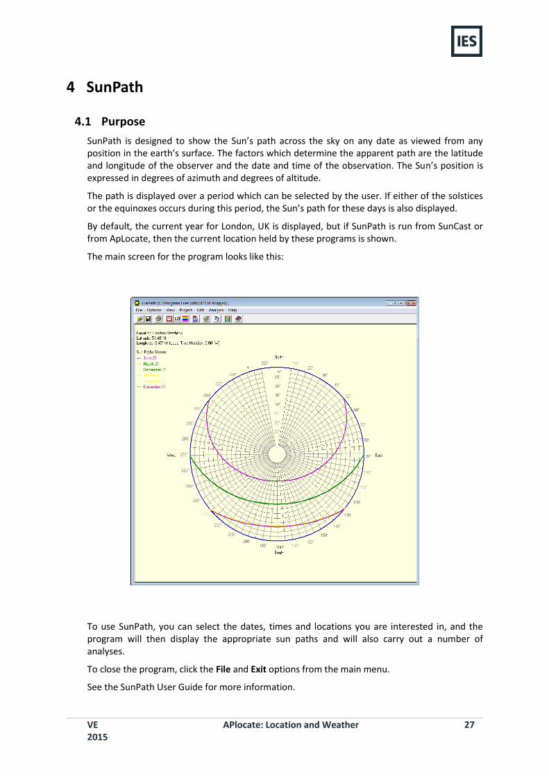
SunPath is designed to show the Sun’s path across the sky on any date as viewed from any position in the earth’s surface. The factors which determine the apparent path are the latitude and longitude of the observer and the date and time of the observation. The Sun’s position is expressed in degrees of azimuth and degrees of altitude.
The path is displayed over a period which can be selected by the user. If either of the solstices or the equinoxes occurs during this period, the Sun’s path for these days is also displayed.
By default, the current year for London, UK is displayed, but if SunPath is run from SunCast or from ApLocate, then the current location held by these programs is shown.
The main screen for the program looks like this:
To use SunPath, you can select the dates, times and locations you are interested in, and the program will then display the appropriate sun paths and will also carry out a number of analyses.
To close the program, click the File and Exit options from the main menu.
See the SunPath User Guide for more information.
VE 2015
APlocate: Location and Weather 28
5 ApLocate Menus Menu items in ApLocate provide the following options:
5.1 File Menu
Save: Saves the design weather data as a *.wea file
Exit: Exits ApLocate
5.2 Options Menu
Graph: Launches the design day graphs dialog
SunPath: Launches SunPath (see section 6)
Remove from custom database: Option to remove any pre-saved custom databases
5.3 Help Menu
Contents: Launches the Help menu
About: Program description and information about IES
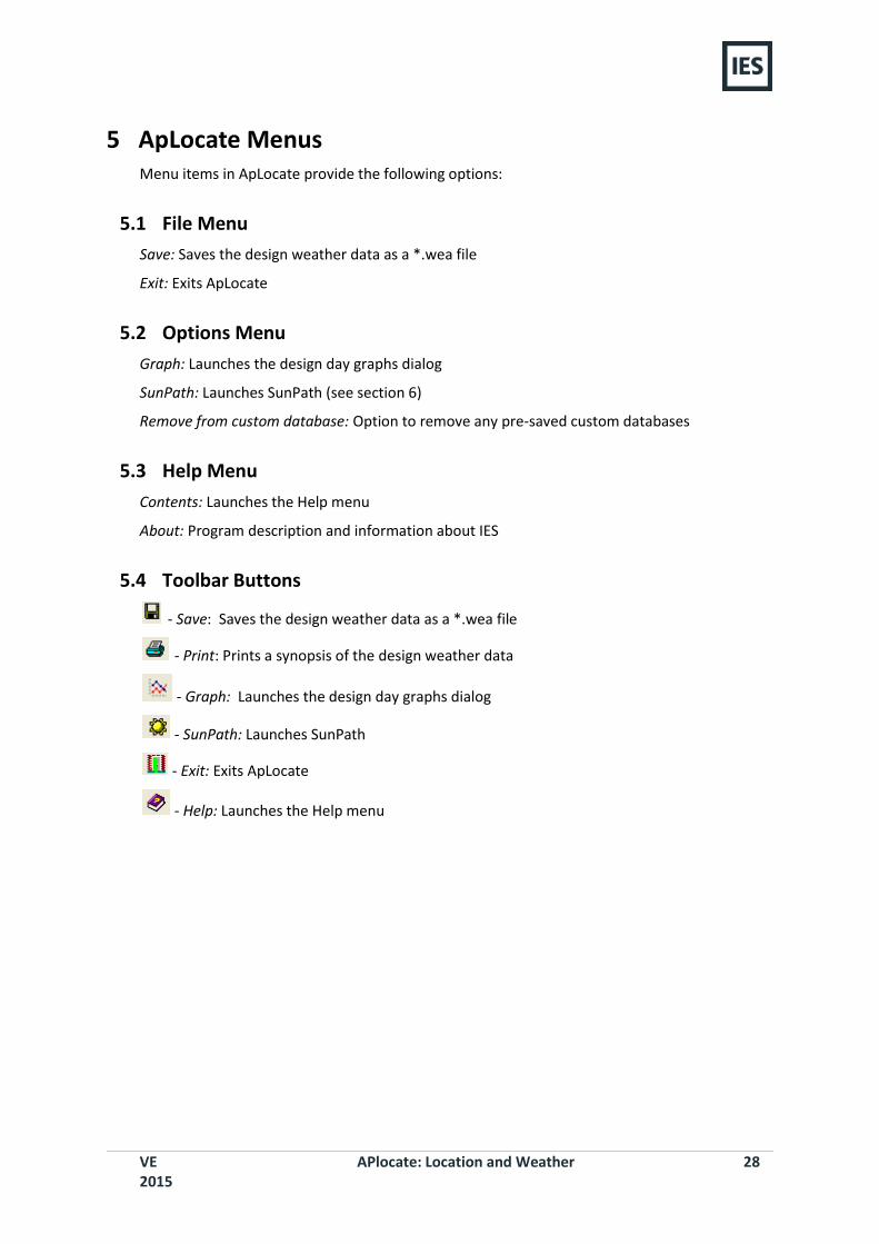
5.4 Toolbar Buttons
- Save: Saves the design weather data as a *.wea file
- Print: Prints a synopsis of the design weather data
- Graph: Launches the design day graphs dialog
- SunPath: Launches SunPath
- Exit: Exits ApLocate
- Help: Launches the Help menu