Embed Size (px)
DESCRIPTION
API2000, Venting Atmospheric and Low-Pressure Storage Tanks
Citation preview

1
Venting Atmospheric and Low-Pressure Storage Tanks Nonrefrigerated Aboveground Tank
BY T. Supunchalee

2
Low pressure storage Tank Pressure is designed for 15 psig (1.034 barg)
15 psig (1bar)
ATM
Pressure vessel
ASME code
API 620
API 650
2 “ (H2O) API 2000
Venting system
(devices)
3
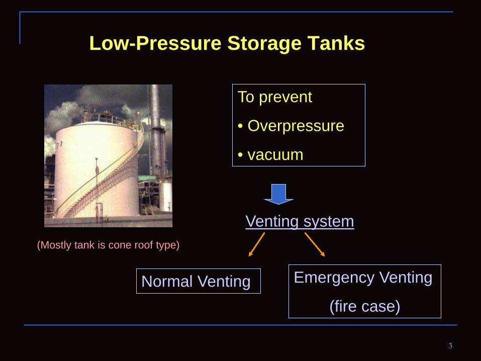
Low-Pressure Storage Tanks
Normal Venting Emergency Venting
(fire case)
To prevent
• Overpressure
• vacuum
(Mostly tank is cone roof type)
Venting system

4
Cause of Overpressure & Vacuum
a. Liquid movement Into tank
Out of tank
Liquid in
Outbreathing Inbreathing
(flashing or feed liquid above boiling point are also considered)
Liquid out
5
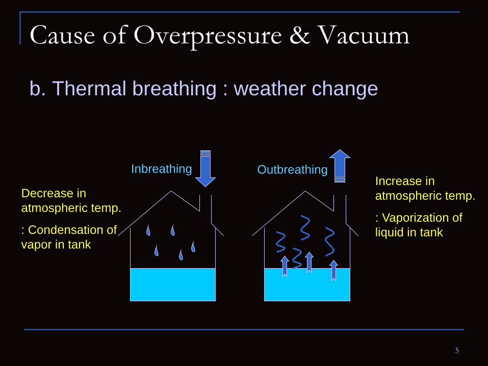
Cause of Overpressure & Vacuum
b. Thermal breathing : weather change
Outbreathing Inbreathing
Decrease in atmospheric temp.
: Condensation of vapor in tank
Increase in atmospheric temp.
: Vaporization of liquid in tank
6
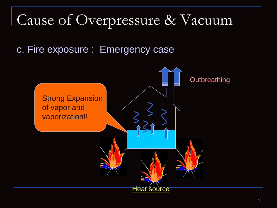
Cause of Overpressure & Vacuum
c. Fire exposure : Emergency case
Strong Expansion of vapor and vaporization!!
Heat source
Outbreathing
7
Cause of Overpressure & Vacuum
External or internal heat transfer device Utility Failure Equipment failed Operating error Chemical reaction Uninsulated Tanks Etc.
d. Other circumstances

8
Venting Requirement
Requirement for normal venting capacity
Requirement for emergency venting capacity
• Liquid movement
• Thermal effect
• Fire exposure

9
Venting Requirement
For normal venting capacity : (Liquid movement)
Flash Point ≥ 100 oF
Boiling point ≥ 300 oF
Flash Point < 100 oF
Boiling point < 300 oF
SCFH of Air per Barrel per Hour of Liquid Flow
Inbreathing outbreathing
5.6
5.6
5.6
5.6
6
6
12
12
(Table 1A : API2000)
10
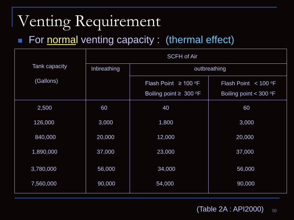
Venting Requirement For normal venting capacity : (thermal effect)
Flash Point ≥ 100 oF
Boiling point ≥ 300 oF
Flash Point < 100 oF
Boiling point < 300 oF
SCFH of Air
Inbreathing outbreathing Tank capacity
(Gallons)
2,500 60 40 60
126,000 3,000 1,800 3,000
840,000 20,000 12,000 20,000
1,890,000 37,000 23,000 37,000
3,780,000 56,000 34,000 56,000
7,560,000 90,000 54,000 90,000
(Table 2A : API2000)
11
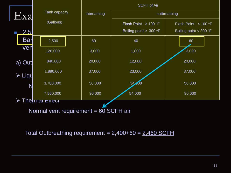
Example 2,500 Gallons storage tank contains benzene. Filling rate = 200
Barrel/hr. And flash point of benzene < 100oF. Determine normal venting requirement.
a) Outbreathing requirement
Liquid movement
Normal vent requirement =
12 x 200 = 2,400 SCFH air
Thermal Effect
Normal vent requirement = 60 SCFH air
Total Outbreathing requirement
= 2,400+60 = 2,460 SCFH
Flash Point ≥ 100 oF
Boiling point ≥ 300 oF
Flash Point < 100 oF
Boiling point < 300 oF
SCFH of Air per Barrel per Hour of Liquid Flow
Inbreathing outbreathing
5.6
5.6
5.6
5.6
6
6
12
12
Flash Point ≥ 100 oF
Boiling point ≥ 300 oF
Flash Point < 100 oF
Boiling point < 300 oF
SCFH of Air
Inbreathing outbreathing Tank capacity
(Gallons)
2,500 60 40 60
126,000 3,000 1,800 3,000
840,000 20,000 12,000 20,000
1,890,000 37,000 23,000 37,000
3,780,000 56,000 34,000 56,000
7,560,000 90,000 54,000 90,000
12
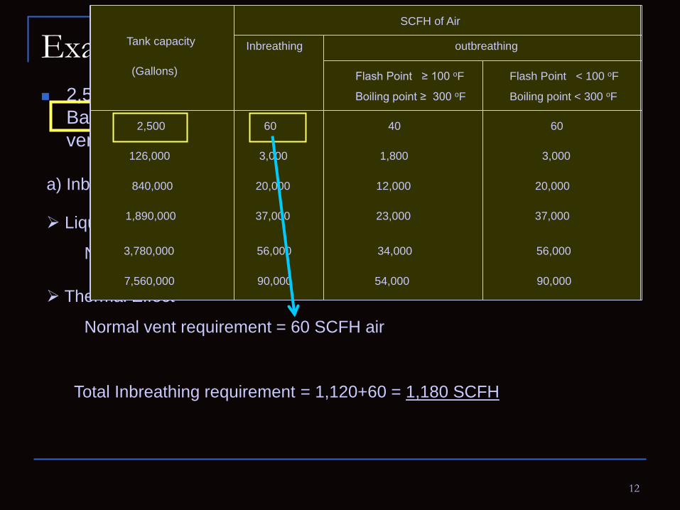
Example (Cont’) 2,500 Gallons storage tank contains benzene. Filling rate = 200
Barrel/hr. And flash point of benzene < 100oF. Determine normal venting requirement.
a) Inbreathing requirement
Liquid movement
Normal vent requirement = 5.6 x 200 = 1,120 SCFH air
Thermal Effect
Normal vent requirement = 60 SCFH air
Total Inbreathing requirement
= 1,120+60 = 1,180 SCFH
Flash Point ≥ 100 oF
Boiling point ≥ 300 oF
Flash Point < 100 oF
Boiling point < 300 oF
SCFH of Air per Barrel per Hour of Liquid Flow
Inbreathing outbreathing
5.6
5.6
5.6
5.6
6
6
12
12
Flash Point ≥ 100 oF
Boiling point ≥ 300 oF
Flash Point < 100 oF
Boiling point < 300 oF
SCFH of Air
Inbreathing outbreathing Tank capacity
(Gallons)
2,500 60 40 60
126,000 3,000 1,800 3,000
840,000 20,000 12,000 20,000
1,890,000 37,000 23,000 37,000
3,780,000 56,000 34,000 56,000
7,560,000 90,000 54,000 90,000

13
Venting Requirement For emergency venting capacity : (Fire exposure)
Tank with weak roof-to-shell Tank without weak roof-to-shell
• Liquid movement
+
• Thermal effect
• Fire exposure < normal venting capacity emergency venting capacity
Venting rate of emergency venting may exceed a combination of normal thermal effect + liquid movement

14
Tank with weak roof-to-shell
Roof
Top angle
Shell
Connection Fail preferentially by frangible joint.!
(**API 650)
***For tank built this specifications, No need to consider venting requirement
15
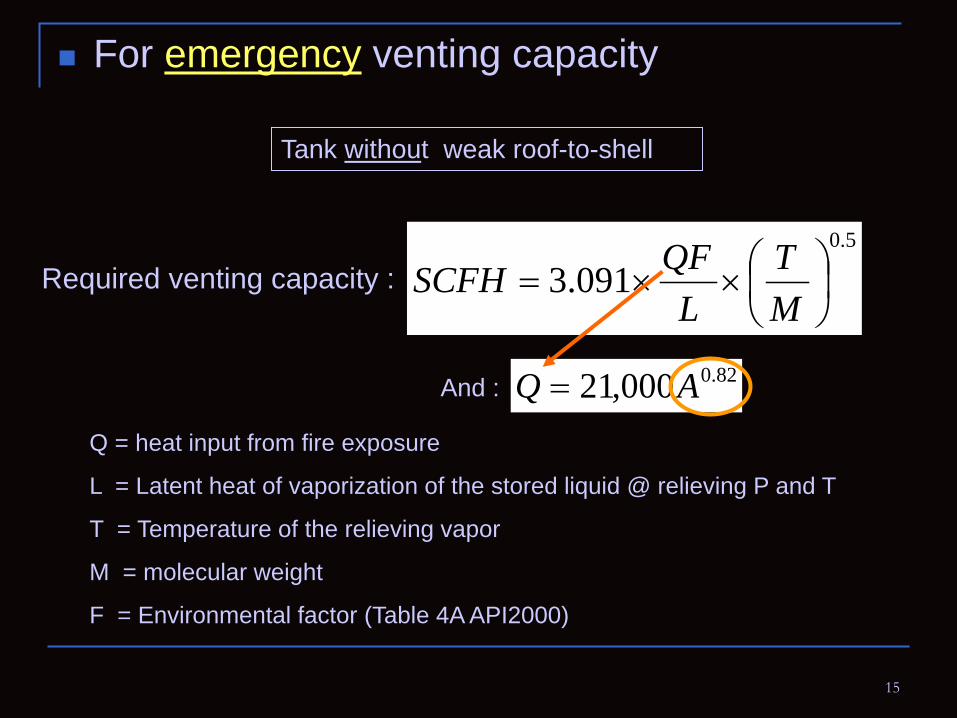
Tank without weak roof-to-shell
5.0
091.3
××=
MT
LQFSCFHRequired venting capacity :
For emergency venting capacity
Q = heat input from fire exposure
L = Latent heat of vaporization of the stored liquid @ relieving P and T
T = Temperature of the relieving vapor
M = molecular weight
F = Environmental factor (Table 4A API2000)
82.0000,21 AQ =And :

16
(Q) (A)
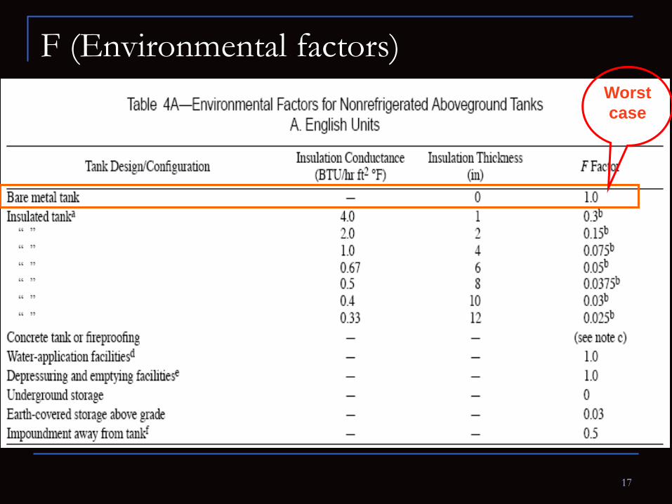
17
F (Environmental factors) Worst case

18
Quick Estimation
For emergency venting capacity
Where a lesser degree of accuracy can be tolerate, the required venting capacity can be determined from Table 3 (API 2000) or Equation 2A (below).
82.01107FASCFH =
Wetted surface area (ft2) Designed pressure (psig) SCFH
< 2800 ≤15 Table 3 (API 2000)
≥ 2800 ≤ 1 742,000
≥ 2800 1< P < 15 Eq. 2A (below)
(Based on Hexane properties)

19
Wetted surface area (ft2) Designed pressure (psig) SCFH
< 2800 ≤15 Table 3 (API 2000)

20
For example: Spherical storage tank has radius of 4 ft. Total area = 4πr2 = 4 π (42) = 145 ft2
wetted area of spherical tank = 55% of 145 ft2 = 80 ft2
Wetted Area of tank (A) shall be calculated by:
Shape of storage tank Wetted area
Sphere and spheroid 55% of total area
Horizontal tanks 75% of total area
Vertical tanks Total area

21
From table A3.
Emergency venting requirement
84,200 SCFH
22
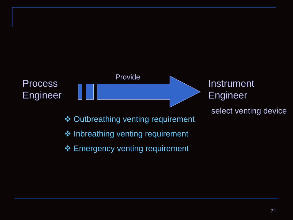
Process Engineer
Instrument Engineer
select venting device
Outbreathing venting requirement
Inbreathing venting requirement
Emergency venting requirement
Provide

23
Means of venting : venting devices
Normal venting
• PV valve (Flame arrester is not considered necessary for
use in conjunction w/ PV valve)
• Open vents w/ flame arrester
• Open vents w/o flame arrester
Flash point below 100oF
Flash point of or above 100oF
(Because Flame speed are less than vapor velocity cross the seat)
24

25
Bird screen
26
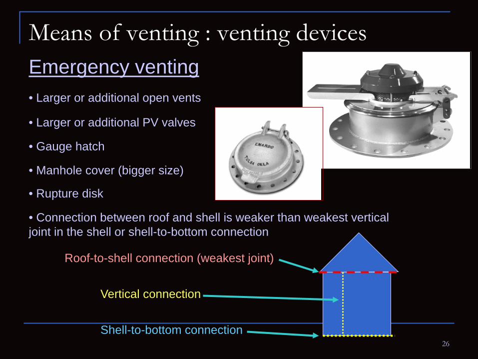
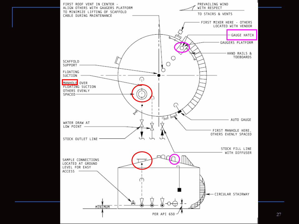
Emergency venting
Means of venting : venting devices
• Larger or additional open vents
• Larger or additional PV valves
• Gauge hatch
• Manhole cover (bigger size)
• Connection between roof and shell is weaker than weakest vertical joint in the shell or shell-to-bottom connection
Roof-to-shell connection (weakest joint)
Vertical connection
Shell-to-bottom connection
• Rupture disk
27
28
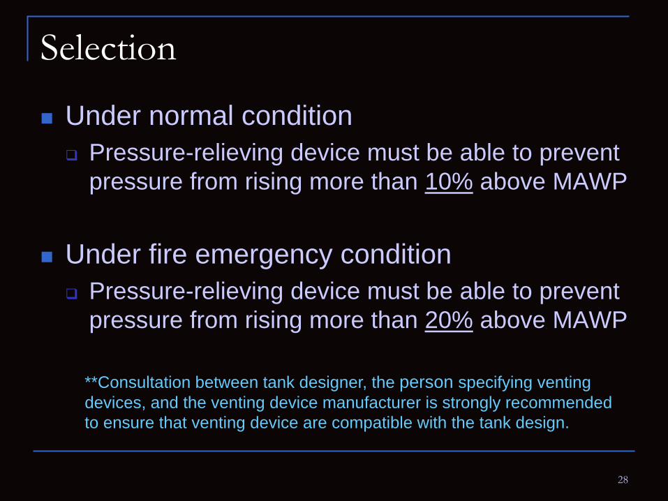
Selection
Under normal condition Pressure-relieving device must be able to prevent
pressure from rising more than 10% above MAWP
Under fire emergency condition Pressure-relieving device must be able to prevent
pressure from rising more than 20% above MAWP **Consultation between tank designer, the person specifying venting devices, and the venting device manufacturer is strongly recommended to ensure that venting device are compatible with the tank design.

29
Discharge piping
1. Lead to a safe area Safe location
tank
- Prevent flame impingement
- Prevent vapor entry in enclosed space

30
Discharge piping
tank
2. Discharge outside of the building
Weak roof-to-shell connection shall not be used inside the building
Inside building
Outside building

31
Discharge piping
Relief device discharge line
Common discharge header

32
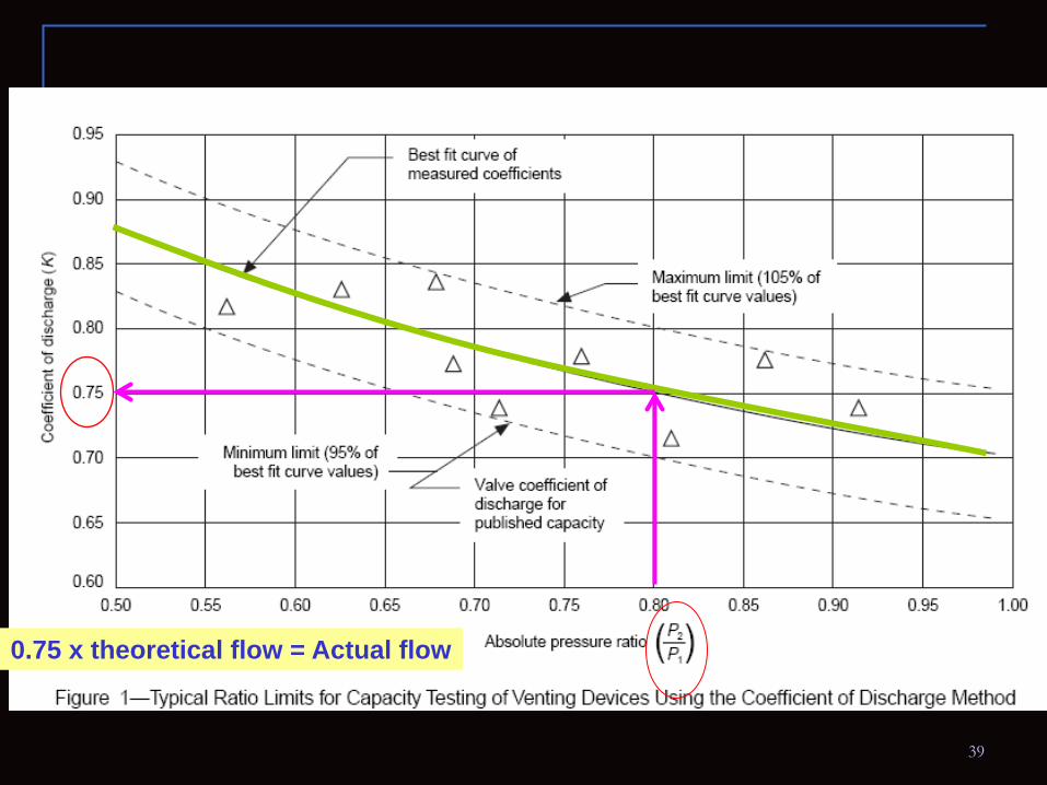
FlowalTheorecticFlowActualK =
−
−
=
+k
kk
PP
PP
kMTZkAPSCFH
1
1
2
2
1
21 )1(
700,278
Measure from actual flow
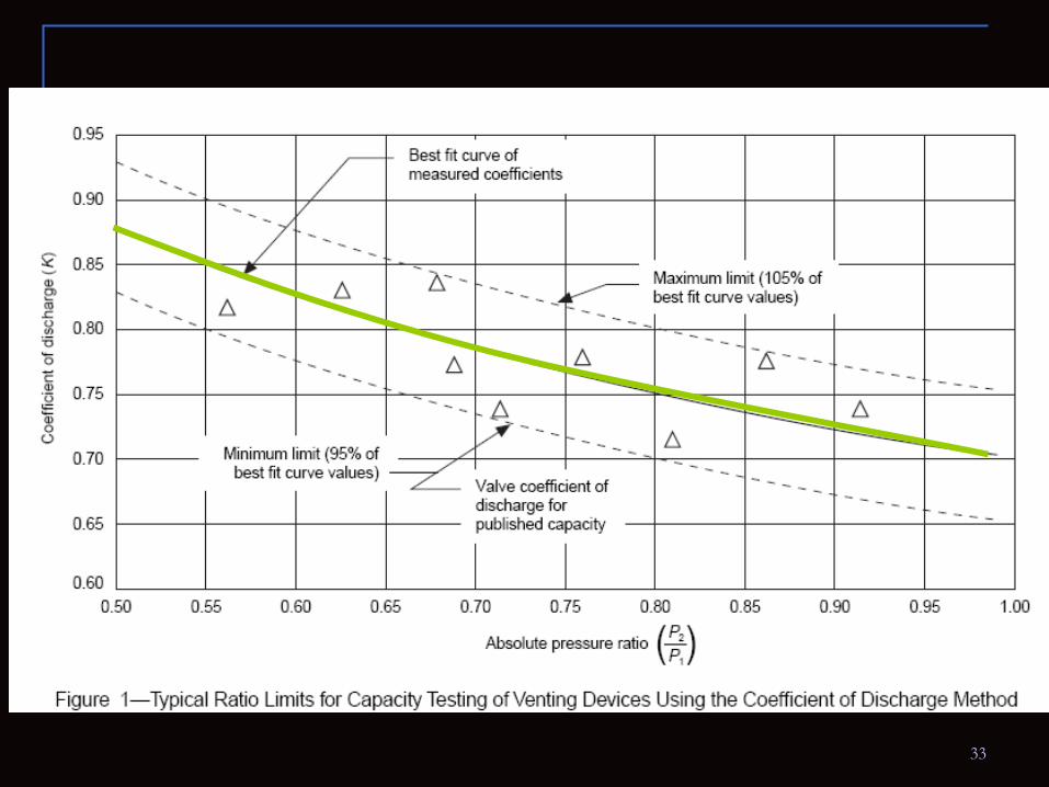
Testing & Sizing
Relief devices should be verified by testing before the devices are place in operation
33
34
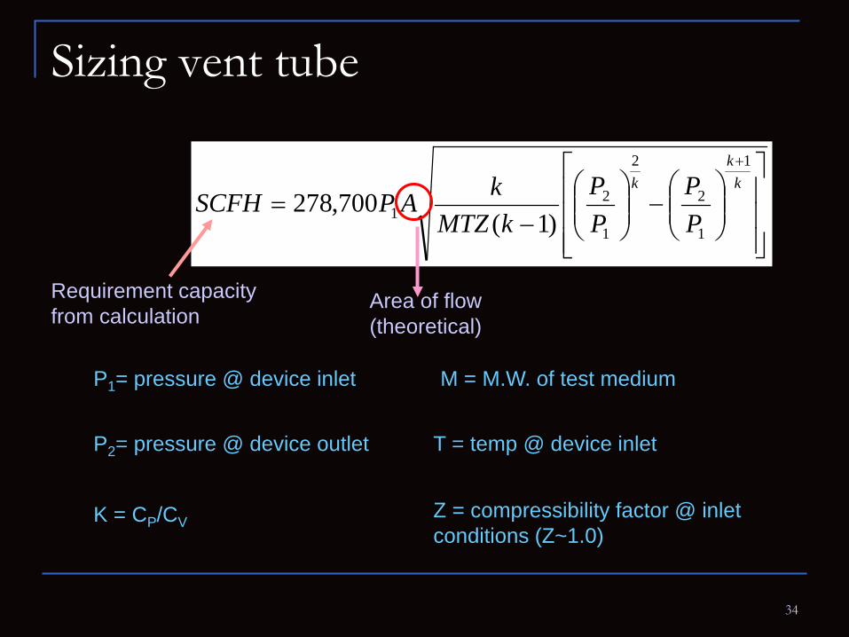
Sizing vent tube
−
−
=
+k
kk
PP
PP
kMTZkAPSCFH
1
1
2
2
1
21 )1(
700,278
Requirement capacity from calculation
Area of flow (theoretical)
P1= pressure @ device inlet
P2= pressure @ device outlet
K = CP/CV
T = temp @ device inlet
M = M.W. of test medium
Z = compressibility factor @ inlet conditions (Z~1.0)
35
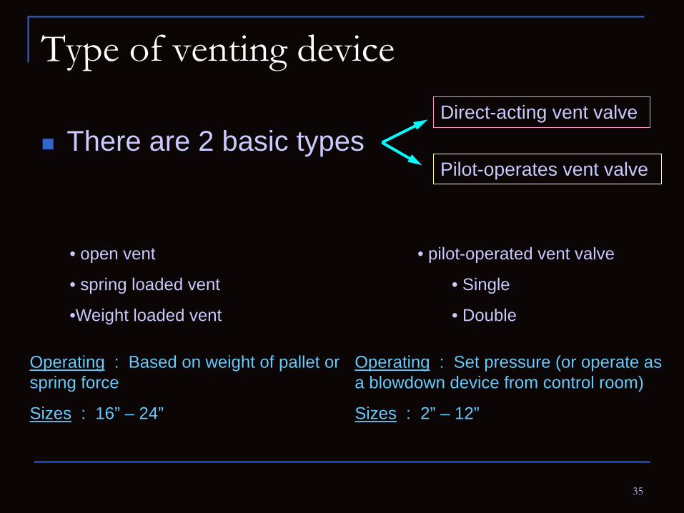
Type of venting device
There are 2 basic types Direct-acting vent valve
Pilot-operates vent valve
• open vent
• spring loaded vent
•Weight loaded vent
Operating : Based on weight of pallet or spring force
Sizes : 16” – 24”
• pilot-operated vent valve
• Single
• Double
Operating : Set pressure (or operate as a blowdown device from control room)
Sizes : 2” – 12”
36

37
Open vent
Spring loaded
Weight loaded
Pilot-operated

38
THANK YOU FOR YOUR ATTENTION
Acknowledgements : - Process section - Mechanic section - Instrument section
39
0.75 x theoretical flow = Actual flow


