Embed Size (px)
Citation preview
Recommended Practice for Design, Operation,and Troubleshooting of Dual Gas-Lift Wells
Version: May 7, 2023
API RECOMMENDED PRACTICE 11V9 (RP 11V9)Draft #6, October 3, 2008
American Petroleum Institute1220 L. Street, NorthwestWashington, DC 20005
API

Issued by
AMERICAN PETROLEUM INSTITUTEProduction Department
FOR INFORMATION CONCERNING TECHNICAL CONTENTS OFTHIS PUBLICATION CONTACT THE API PRODUCTION DEPARTMENT,
2535 ONE MAIN PLACE, DALLAS, TX 75202 - (214) 748-3841.SEE BACK COVER FOR INFORMATION CONCERNING
HOW TO OBTAIN ADDITIONAL COPIES OF THIS PUBLICATION.
Users of this publication should become familiar with its scopeand content. This publication is intended to supplement rather
than replace individual engineering judgement.
Official Publication
APIReg. U.S. Patent Office
Copyright @ l993 American Petroleum Institute
API RP 11V9 Recommended Practices for Design, Operation, Page iiiand Troubleshooting of Dual Gas-Lift Wells
Foreword
This publication is under the jurisdiction of the API Committee on Standardization of Production Equipment.
American Petroleum Institute (API) Specifications are published as aids for the procurement of standardized equipment and materials, as instructions to manufacturers of equipment and materials, and as instructions to manufacturers of equipment or materials covered by an API Specification. These Specifications are not intended to obviate the need for sound engineering practice, nor to inhibit in any way anyone from purchasing or producing products to other specifications.
The formulation and publication of API Specifications and the API monogram program are not intended in any way to inhibit the purchase of products from companies not licensed to use the API monogram.
API Specifications may be used by anyone desiring to do so, and diligent effort has been made by the Institute to assure the accuracy and reliability of the data contained therein. However, the Institute makes no representation, warranty, or guarantee in connection with the publication of any API Specification and hereby expressly disclaims any liability or responsibility for loss or damage resulting from their use, for any violation of any federal, state, or municipal regulation with which an API Specification may conflict, or for the infringement of any patent resulting from the use of an API Specification.
Any manufacturer producing equipment or materials represented as conforming with an API Specification is responsible for conforming with all the provisions of that Specification. The American Petroleum Institute does not represent, warrant, or guarantee that such products do in fact conform to the applicable API standard or specification.
This Standard shall become effective on the date printed on the cover but may be used voluntarily from the date of distribution.
Attention Users of This Publication: Portions of this publication have been changed from the previous edition. In some cases the changes are significant, while in other cases the changes reflect minor editorial adjustments.
Note:
This is the first edition of this recommended practice.
Requests for permission to reproduce or translate all or any part of the material published herein should be addressed to the Director, American Petroleum Institute, Production Department, 2535 One Main Place, Dallas, TX 75202.

API RP 11V9 Recommended Practices for Design, Operation, Page ivand Troubleshooting of Dual Gas-Lift Wells
Policy
API PUBLICATIONS NECESSARILY ADDRESS PROBLEMS OF A GENERAL NATURE. WITH RESPECT TO PARTICULAR CIRCUMSTANCES, LOCAL, STATE, AND FEDERAL LAWS AND REGULATIONS SHOULD BE REVIEWED.
API IS NOT UNDERTAKING TO MEET THE DUTIES OF EMPLOYERS, MANUFACTURERS, OR SUPPLIERS TO WARN AND PROPERLY TRAIN AND EQUIP THEIR EMPLOYEES, AND OTHER EXPOSED PERSON, CONCERNING HEALTH AND SAFETY RISKS AND PRECAUTIONS, NOR UNDERTAKING THEIR OBLIGATIONS UNDER LOCAL, STATE, OR FEDERAL LAWS.
NOTHING CONTAINED IN ANY API PUBLICATION IS TO BE CONSTRUED AS GRANTING ANY RIGHT, BY IMPLICATION OR OTHERWISE, FOR THE MANUFACTURE, SALE, OR USE OF ANY METHOD, APPARATUS, OR PRODUCT COVERED BY LETTERS PATENT. NEITHER SHOULD ANYTHING CONTAINED IN THE PUBLICATION BE CONSTRUED AS INSURING ANYONE AGAINST LIABILITY FOR INFRINGEMENT OF LETTERS PATENT.
GENERALLY, API STANDARDS ARE REVIEWED AND REVISED, REAFFIRMED, OR WITHDRAWN AT LEAST EVERY FIVE YEARS. SOMETIMES A ONE-TIME EXTENSION OF UP TO TWO YEARS WILL BE ADDED TO THIS REVIEW CYCLE. THIS PUBLICATION WILL NO LONGER BE IN EFFECT FIVE YEARS AFTER ITS PUBLICATION DATE AS AN OPERATIVE API STANDARD OR, WHERE AN EXTENSION HAS BEEN GRANTED, UPON REPUBLICATION. STATUS OF THE PUBLICATION CAN BE ASCERTAINED FROM THE API AUTHORING DEPARTMENT (TEL. 214-220-911 1). A CATALOG OF API PUBLICATIONS AND MATERIALS IS PUBLISHED ANNUALLY AND UPDATED QUARTERLY BY API, 1220 L ST., N.W., WASHINGTON, D.C. 20005.
API RP 11V9 Recommended Practices for Design, Operation, Page 5and Troubleshooting of Dual Gas-Lift Wells
Table of Contents
Subject Page
1 Introduction..........................................................................................................121.1 Purpose of this document.....................................................................................121.2 Why dual wells exist..............................................................................................13
1.2.1 Lower drilling cost........................................................................................131.2.2 Insufficient surface space............................................................................151.2.3 Multi-lateral completions..............................................................................151.2.4 Completion/operation concerns...................................................................16
2 Dual Gas-Lift Overview........................................................................................162.1 Goals of dual gas-lift..............................................................................................16
2.1.1 Inject in both strings simultaneously............................................................162.1.2 Inject as deep as possible in both sides......................................................172.1.3 Inject in a stable manner.............................................................................172.1.4 Inject at an optimum rate.............................................................................17
2.2 Problems associated with dual gas-lift................................................................172.2.1 Completion issues associated with dual gas-lift..........................................172.2.2 Design issues..............................................................................................192.2.3 Operational issues.......................................................................................202.2.4 Control issues..............................................................................................222.2.5 Surveillance issues......................................................................................242.2.6 Alternatives to dual gas-lift..........................................................................27
3 Recommended Practices.....................................................................................283.1 Practices that are recommended..........................................................................28
3.1.1 Selecting acceptable dual gas-lift candidates (from Chapter 4)...................283.1.2 Staffing dual gas-lift operations (from Chapter 5)........................................293.1.3 Dual gas-lift design (from Chapter 6)...........................................................293.1.4 Dual gas-lift operation (from Chapter 7)......................................................313.1.5 Dual gas-lift surveillance (from Chapter 8)..................................................333.1.6 Dual gas-lift diagnosis and troubleshooting (from Chapter 9)......................343.1.7 Dual gas-lift automation (from Chapter 10)..................................................353.1.8 Dual gas-lift special issues (from Chapter 11).............................................36
3.2 Practices that are not recommended...................................................................373.2.1 Selecting dual gas-lift candidates (from Chapter 4).....................................373.2.2 Dual gas-lift staff (from Chapter 5)..............................................................373.2.3 Dual gas-lift design (from Chapter 6)...........................................................373.2.4 Dual gas-lift operation (from Chapter 7)......................................................373.2.5 Dual gas-lift surveillance (from Chapter 8)..................................................383.2.6 Dual gas-lift diagnosis and troubleshooting (from Chapter 9)......................383.2.7 Dual gas-lift automation (from Chapter 10)..................................................383.2.8 Dual gas-lift special issues (from Chapter 11).............................................38
4 Candidates and Screening Criteria for Dual Gas-Lift.......................................384.1 Wells that are acceptable candidates for dual gas-lift........................................39
4.1.1 Economics...................................................................................................39
API RP 11V9 Recommended Practices for Design, Operation, Page 6and Troubleshooting of Dual Gas-Lift Wells
4.1.2 Operational issues.......................................................................................404.1.3 Recommended practices for selecting acceptable candidates....................41
4.2 Wells that are not good candidates for dual gas-lift...........................................414.2.1 Two zones too far apart...............................................................................424.2.2 Low formation GOR.....................................................................................424.2.3 Need to intermittent one or both sides.........................................................424.2.4 Small casing size.........................................................................................424.2.5 Recommended practices to avoid some wells.............................................42
4.3 Reasons to consider artificial lift alternatives rather than dual gas-lift............424.3.1 If can afford to complete the wells as singles..............................................424.3.2 More costly to complete and perform workovers, abandonment.................434.3.3 Expertise needed to successfully operate duals is lacking in company.......434.3.4 It is allowed and technically feasible to commingle.....................................434.3.5 Potential need for remedial work below end of short string tubing..............434.3.6 Having duals makes surveillance using casing pressure more difficult.......434.3.7 Recommended practices to consider alternatives to dual gas-lift................43
5 Commitment Required for Successful Dual Gas-Lift........................................445.1 Commitment required by management................................................................44
5.1.1 Be informed on business issues/economics of dual gas-lift.........................445.1.2 Foster continuous improvement..................................................................445.1.3 Provide continuity of artificial lift team or champion.....................................445.1.4 Allow access for champion to management................................................445.1.5 Provide long term training and support on dual gas-lift...............................455.1.6 Use drilling/completion savings for increased operating/surveillance costs.455.1.7 Recommended practices for management of dual gas-lift systems............45
5.2 Commitment required by engineering..................................................................455.2.1 “Go to school” on dual gas-lift – continuing education.................................455.2.2 Understand API RP 11V8 (Systems) and API RP 11V9 (Dual Gas-Lift).....455.2.3 Understand needs and responsibilities of other engineering disciplines.....465.2.4 Understand operational issues that affect dual gas-lift................................475.2.5 Awareness of increased impact on duals of adverse downhole concerns...475.2.6 Awareness of inter-zone interference..........................................................485.2.7 Understand personnel issues that affect dual gas-lift..................................485.2.8 Recommended practices for engineering dual gas-lift systems...................49
5.3 Commitment required by members of dual gas-lift team...................................495.3.1 “Go to school” on dual gas-lift – continuing education.................................505.3.2 Understand API RP 11V8 (Systems) and API RP 11V9 (Dual Gas-Lift).....505.3.3 Be open to perceiving that work on dual gas-lift is advantageous...............505.3.4 Maintain lines of communication with engineering/champion......................505.3.5 Participate fully on dual gas-lift team...........................................................505.3.6 Document economic gains/benefits of working on dual gas-lift...................505.3.7 Recommended practices for the dual gas-lift team.....................................51
5.4 Commitment required by trainers, others............................................................515.4.1 Develop and deliver effective dual gas-lift training programs......................515.4.2 Recommended practices for trainers, others...............................................52
6 Designing Dual Gas-Lift Wells............................................................................536.1 Mandrel spacing.....................................................................................................53
6.1.1 Design spacing based on requirements of lower zone................................53
API RP 11V9 Recommended Practices for Design, Operation, Page 7and Troubleshooting of Dual Gas-Lift Wells
6.1.2 Design spacing based on requirements of most prolific zone......................536.1.3 Design spacing for each side of the dual based on its conditions/needs.....546.1.4 Design with flexibility to allow use of different types of valves.....................546.1.5 Gas-lift mandrel spacing production pressure “design line” options............556.1.6 Recommended gas-lift mandrel spacing design procedure.........................576.1.7 Be aware of installation issues....................................................................586.1.8 Recommended practices for mandrel spacing............................................59
6.2 When one zone is much deeper than other side.................................................596.2.1 Alternatives if two zones are vertically far apart..........................................596.2.2 Recommended practices when one zone is significantly deeper................61
6.3 The PPO vs. IPO gas-lift valve debate..................................................................616.3.1 PPO support, logic, and issues...................................................................626.3.2 Support, logic, and issues associated with using IPO valves......................626.3.3 Balanced IPO (continuous or constant flow) valve support, logic, issues....656.3.4 Differential valve support, logic, and issues.................................................666.3.5 Recommended practices for selecting type of unloading valve...................67
6.4 Unloading gas-lift valves.......................................................................................676.4.1 Unloading valve design for each type of valve............................................676.4.2 Recommended practices for unloading valve design..................................67
6.5 Operating gas-lift valve or orifice.........................................................................676.5.1 Alternatives for operating gas-lift valve or orifice.........................................676.5.2 Recommended practices for operating gas-lift valve or orifice....................69
6.6 Designing for dual gas-lift if mandrels spaced too far apart..............................696.6.1 May need to use IPO, at least in upper mandrels........................................706.6.2 Possible use of pack-off valves...................................................................706.6.3 Possible use of concentric string.................................................................706.6.4 Recommended practices if mandrels are too far apart................................70
6.7 Review of various dual gas-lift design options...................................................706.7.1 PPO valves on both sides...........................................................................706.7.2 IPO valves high in the hole, PPO valves lower in the hole..........................706.7.3 IPO valves on one side, PPO valves on the other side...............................716.7.4 IPO valves on both sides.............................................................................716.7.5 Single point injection...................................................................................716.7.6 Recommended practices for considering various design options................71
7 Operation of Dual Gas-Lift Wells........................................................................727.1 Installing dual gas-lift equipment.........................................................................72
7.1.1 Running two strings together “simultaneously”............................................727.1.2 Running two strings separately...................................................................727.1.3 Consideration if there must be multiple packers on long string...................727.1.4 Surface-controlled (electric, hydraulic, cable-less) gas-lift valves................737.1.5 Chemical lines.............................................................................................737.1.6 Testing the packer.......................................................................................737.1.7 Recommended practices for installing dual gas-lift equipment....................74
7.2 Wireline operations in dual gas-lift wells.............................................................747.2.1 Possibility of cross flow when changing gas-lift equipment in a dual well....747.2.2 Changing gas-lift valves in a dual completion..............................................757.2.3 Recommended practices for wireline operations.........................................76
7.3 Recommended wire line procedures....................................................................76
API RP 11V9 Recommended Practices for Design, Operation, Page 8and Troubleshooting of Dual Gas-Lift Wells
7.3.1 Running gas-lift valves in dual gas-lift wells................................................767.3.2 Installing valves when dummy valves are in the other string.......................767.3.3 Recommended practices when performing wireline operations..................767.3.4 Alternate procedure (with dummy valves in the other string).......................777.3.5 Installing valves in duals with live valves in the other string........................787.3.6 Installing valves on the higher pressured zone............................................787.3.7 Other methods.............................................................................................797.3.8 Gas-lift valve installation problems..............................................................807.3.9 Recommended practices for wireline operations.........................................81
7.4 Unloading dual gas-lift wells.................................................................................817.4.1 Options for unloading dual gas-lift wells......................................................827.4.2 Recommendations for unloading dual gas-lift wells.....................................827.4.3 Recommended practices for unloading dual gas-lift wells...........................84
7.5 Kicking off dual gas-lift wells................................................................................847.5.1 Recommendations for kicking off (restarting) dual gas-lift wells..................857.5.2 Recommended practices for kicking off (restarting) dual gas-lift wells........86
7.6 Operating dual gas-lift wells.................................................................................867.6.1 Keep both zones on production...................................................................867.6.2 Keep both zones deep, stable, and optimum..............................................867.6.3 Inject the correct amount of gas..................................................................877.6.4 Inject at the correct pressure.......................................................................877.6.5 Operation when one or both zones are being tested...................................887.6.6 Operation during pressure surveys.............................................................887.6.7 Manual operation.........................................................................................887.6.8 Semi-automatic operation............................................................................887.6.9 Automatic operation....................................................................................887.6.10 Recommended practices for operating dual gas-lift wells............................88
7.7 Optimizing dual gas-lift wells................................................................................897.7.1 Definition of optimization for dual gas-lift.....................................................897.7.2 Determination of optimum injection rate......................................................897.7.3 Gas-lift allocation, staying near optimum.....................................................907.7.4 Recommended practices for optimizing dual gas-lift wells..........................91
8 Surveillance of Dual Gas-Lift Wells....................................................................918.1 Wireline operations in gas-lift completions.........................................................928.2 Pressure/temperature surveys..............................................................................92
8.2.1 Static Bottom-hole Pressure (SBHP) Survey...............................................928.2.2 Flowing Bottom-hole Pressure (FBHP) Survey...........................................938.2.3 Memory Production Logging Tools..............................................................938.2.4 Recommended practices for running pressure/temperature surveys..........94
8.3 Using pressure/temperature surveys to evaluate and diagnose dual gas-lift. .948.3.1 Determine well’s productivity.......................................................................948.3.2 Diagnose/troubleshoot gas-lift performance................................................958.3.3 Recommended practices for using pressure/temperature surveys..............96
8.4 Fluid levels..............................................................................................................968.4.1 Maximum depth to which well has been unloaded......................................978.4.2 Checking for leaks.......................................................................................978.4.3 Recommended practices for running, using fluid levels..............................97
8.5 Well tests................................................................................................................97
API RP 11V9 Recommended Practices for Design, Operation, Page 9and Troubleshooting of Dual Gas-Lift Wells
8.5.1 Test each well, with the other producing.....................................................978.5.2 Test each well, with other well closed in......................................................988.5.3 Test both wells, with both wells in test separator at same time...................988.5.4 Recommended practices for conducting, using well tests...........................99
8.6 CO2 tracer................................................................................................................998.6.1 Can use to determine highest injection point...............................................998.6.2 Can tell if either side is multi-pointing..........................................................998.6.3 Difficult to determine depth of lower injection point(s).................................998.6.4 Recommended practices for running, using CO2 tracer surveys...............100
8.7 Continuous monitoring and control...................................................................1008.7.1 Methods of continuous monitoring.............................................................1008.7.2 What to monitor.........................................................................................1008.7.3 Manual methods........................................................................................1018.7.4 Chart recorders and manual control valves...............................................1018.7.5 Electronic measurements and flow controllers..........................................1028.7.6 Production automation systems................................................................1028.7.7 Optimum monitoring frequency.................................................................1028.7.8 Making use of monitored information........................................................1038.7.9 Recommended practices for continuous monitoring..................................103
9 Diagnosis and Troubleshooting.......................................................................1039.1 Diagnostic techniques.........................................................................................104
9.1.1 Library of typical problems.........................................................................1049.1.2 Comparison with two-pen charts...............................................................1049.1.3 Comparison of flowing pressure surveys...................................................1059.1.4 Measurements of well performance..........................................................1059.1.5 Calibration of gas-lift model.......................................................................1079.1.6 Compare current measurements with calibrated model............................1079.1.7 Exception reporting of deviations..............................................................1089.1.8 Recommended practices for selecting dual gas-lift diagnostic techniques 108
9.2 Methods to locate communication problems....................................................1099.2.1 Proving communication.............................................................................1099.2.2 Methods for Locating Tubing-Casing Communication...............................1109.2.3 Recommended practices for locating communication problems................111
9.3 Examples of typical dual gas-lift problems........................................................1119.3.1 Higher backpressure than the original designed conditions......................1119.3.2 Lower injection pressure than the original designed conditions.................1119.3.3 Higher injection pressure than the original designed conditions................1119.3.4 One string will not take injection gas or takes too little gas........................1129.3.5 One string taking more injection gas than its designed rate......................1129.3.6 One string has pressure depleted and is shut-in.......................................1129.3.7 Tubing-casing communication...................................................................1129.3.8 Wells that produce emulsions....................................................................1129.3.9 Sand production........................................................................................1139.3.10 Other typical gas-lift problems...................................................................1139.3.11 Recommended practices for understanding example problems................114
10 Automation of Dual Gas-Lift Wells...................................................................11410.1 Gas-lift automation logic.....................................................................................114
10.1.1 Recommended practices for automatic logic.............................................114
API RP 11V9 Recommended Practices for Design, Operation, Page 10and Troubleshooting of Dual Gas-Lift Wells
10.2 What to measure..................................................................................................11510.2.1 Required well measurements....................................................................11510.2.2 Optional well measurements.....................................................................11510.2.3 Required system measurements...............................................................11610.2.4 Optional system measurements................................................................11610.2.5 Recommended practices for automatic measurements............................117
10.3 What to control.....................................................................................................11710.3.1 Required well control.................................................................................11710.3.2 Optional well controls................................................................................11710.3.3 Required system control............................................................................11810.3.4 Optional system controls...........................................................................11810.3.5 Recommended practices for automatic controls........................................118
10.4 Responding to gas-lift system problems...........................................................11810.4.1 Gas-lift system upsets...............................................................................11810.4.2 Restarting after an upset...........................................................................11910.4.3 Controlling the well during well testing......................................................11910.4.4 Responding to an obvious gas-lift problem in the well...............................11910.4.5 Recommendations for automatic response to gas-lift system problems....119
11 Special Issues.....................................................................................................11911.1 When gas-lift co-exists with a flowing well in the same wellbore....................119
11.1.1 Important considerations...........................................................................11911.1.2 Recommended practices when a flowing and gas-lift well co-exist...........120
11.2 When gas-lift co-exists with a pumping well in the same wellbore.................12111.2.1 Important considerations...........................................................................12111.2.2 Recommended practices when a pumping and gas-lift well co-exist.........121
11.3 When one or both zones should be intermitted................................................12211.3.1 Important considerations...........................................................................12211.3.2 Recommended practices when one or both zones should be intermitted. 123
11.4 When one zone completed with mandrels, one without mandrels..................12311.4.1 Important considerations...........................................................................12311.4.2 Recommended practices when one zone doesn’t have mandrels.............124
11.5 How to transition from flowing to dual gas-lift operation.................................12411.5.1 When to convert from flowing to gas-lift?...................................................12511.5.2 Recommended practices to transition from flowing to dual gas-lift............125
12 Dual Gas-Lift Mandrel Spacing Design............................................................12612.1 Well description....................................................................................................12612.2 Design assumptions............................................................................................12612.3 Mandrel spacing design for the long string.......................................................12712.4 Calculated long string mandrel depths..............................................................12812.5 Calculated short string mandrel depths.............................................................12812.6 Graphical design..................................................................................................128
13 Dual Gas-Lift Unloading Valve Design for PPO Valves..................................13013.1 Step 1 --- Depth of perforations...........................................................................130
API RP 11V9 Recommended Practices for Design, Operation, Page 11and Troubleshooting of Dual Gas-Lift Wells
13.2 Step 2 --- Injection gas gradient line...................................................................13013.3 Step 3 --- Flowing pressure gradient line...........................................................13013.4 Step 4 --- Transfer pressure for each gas-lift valve...........................................13013.5 Step 5 --- Safety factor.........................................................................................13013.6 Step 6 --- Gas-lift valve port size.........................................................................13113.7 Step 7 --- Test rack opening pressure................................................................13113.8 Step 8 --- Opening pressure at depth.................................................................13113.9 Step 9 --- Valve or orifice at operating depth.....................................................13113.10 Graphical method for designing PPO gas-lift valves........................................13213.11 Valve calculations for PPO gas-lift valves..............................................................133
API RP 11V9 Recommended Practices for Design, Operation, Page 12and Troubleshooting of Dual Gas-Lift Wells
API RP 11V9 – Recommended Practice for Dual Gas-Lift
This document is one of a series of recommended practices (RP's) produced by the American Petroleum Institute (API) for use by oil-field engineers, operators, and others around the world. This RP focuses on dual gas-lift.
1 Introduction
This API recommended practice provides guidelines and tools to facilitate the effective and efficient design, operation, optimization, and troubleshooting of dual gas-lift completions. As used in this document, a dual completion is one in which there are two producing zones, each with its own tubing string, in a single production casing. So, there are two separate producing wells, with one common annulus.
It is sometimes concluded, in the development of fields with multiple reservoirs, that the economic benefits of dual completions outweigh the operational problems that frequently result from trying to effectively produce a dual completion and the higher operating and workover costs that may occur over the producing life. Thus, dual completions (and occasionally even triples) are sometimes attempted to reduce upfront drilling costs and accelerate production from the multiple reservoirs.
This document focuses on the issues that must be faced when it becomes necessary to artificially lift both sides of a dual completion with gas-lift. Management of the problems facing operators of dual gas-lift wells may be easier and more successful if the recommended practices in this document are followed.
1.1 Purpose of this document
The purpose of this document is to provide recommended practices for the design, operation, optimization, and troubleshooting of dual gas-lift wells. Compared to single completions, dual completions have a higher initial cost, have more operating problems, are more difficult and expensive to work over, and often produce less efficiently. Based on experience, most technical gas-lift specialists and operations staff prefer single completions to duals.
It is not the purpose of this document to recommend the practice of dual gas-lift. In many cases, dual gas-lift is problematic and often it is ineffective. Often, it is difficult or even impossible to effectively produce both completions in a dual well using gas-lift, over the long term. If there are other feasible alternatives to produce dual wells, they should be considered.
However many dually-completed oil wells must be artificially lifted - either initially or after reservoir pressures have declined and/or water cuts have increased. And in many cases, the only practical or feasible method of artificial lift for these wells is gas-lift. So, if dual wells must be artificially lifted, and if the only practical or feasible means to do this is with gas-lift, every effort must be made to perform this dual gas-lift function as effectively as possible.
Therefore, the purpose of this document is to offer recommended practices, guidelines, and tools to “make the best of what may otherwise be a difficult situation.” However, unlike most recommended practices, this document also contains discussion of practices that are not recommended. That is, it contains suggestions on practices that should be avoided to minimize problems, inefficiencies, and poor economics that may be associated with ineffective dual gas-lift operations.
API RP 11V9 Recommended Practices for Design, Operation, Page 13and Troubleshooting of Dual Gas-Lift Wells
1.2 Why dual wells exist
Dual wells exist for a number of reasons. The primary ones are summarized in this Section.
1.2.1 Lower drilling cost
The primary reason why duals exist is economics. It is often less expensive to drill one wellbore to serve two (or more) vertically oriented production zones, than to drill two or more separate wells to reach these same zones.
In some fields, there are multiple reservoirs "stacked" on top of each other. In some fields, there may be as many as five, ten, or even more separate reservoirs located vertically above one another. The development plans for such fields are often complex and require an economic study that must consider the initial drilling and completion costs plus the producing costs, workover costs, and the potential production rates over the life of the field.
The objective is normally to produce the reserves as quickly as feasible, and realize the highest profits, while protecting the environment and being good world citizens. Multiple completions that result in significant loss or deferment of reserves, prolonged producing lives, and much higher producing and workover costs are not recommended. It is very tempting, economically, to drill one well to intersect several reservoirs, and to produce more than one of the reservoirs at the same time with the same well, to minimize overall costs and to accelerate overall production. But this must be done correctly, or the economic benefits may not be achieved.
But why, one might ask, can't multiple zones be produced in the same completion without the need for trying to operate dual completions? In selecting the best possible development for multiple zone reservoirs, there are a number of choices that need to be carefully analyzed.
1.1.2.1 Choices to be made when there are multiple zones
Produce each separate reservoir one at a time . The first alternative to be considered should be one where the zones are not commingled. Drill to the deepest zone and produce the lowest zone to its economic limit. Plug back to the next lowest zone, produce it, and continue until all zones are depleted. The basic disadvantage of this simple approach is the resulting long life. Development costs are relatively low but the income from the production is spread out over many years and thus the present day value of the income is reduced. Also well spacing and location may not be ideal for all the reservoirs. Another problem with this approach is that offset development by other operators may drain the reserves from the un-produced reservoirs held by the first operator.
Drill a separate well for each reservoir . Another approach is to drill separate individual wells to each reservoir. Each reservoir is treated separately and well spacing and location are selected for each individual reservoir. This may be the best approach where well costs are relatively low (i.e. shallow hydro-pressured reservoirs.) Initial drilling and development costs are significantly higher using this approach, since more wells must be drilled and completed, but operational problems are only the ones associated with single completions. However, development of reservoirs with low reserves
API RP 11V9 Recommended Practices for Design, Operation, Page 14and Troubleshooting of Dual Gas-Lift Wells
may not be justified if they must be developed with a separate single production well.
Commingle the production from multiple reservoirs . In some cases, commingling of production down-hole from different reservoirs is the best approach. This must be done with care, as there are several potential problems. And, in some cases, it is not allowed to commingle multiple zones in the same wellbore. Challenges to downhole commingling can occur:
Because of field “rules” or governmental regulations . Sometimes such rules were developed due to complications with commingling in the early 1900’s. Poor choices were made in the completion design and reserves were lost. In some cases cross-flow downhole resulted and production measurement from the individual reservoirs was poor. Such problems need to be prevented; however, with proper design and good operating practices, commingling may be an acceptable approach and a much simpler approach than using dual or multi-completions.
Because of “ownership.” In some cases, different parties own the mineral rights in different zones. Good measurement from each zone is essential if commingling is to be allowed.
Because fluid properties and reservoir pressures are significantly different. In some cases, the pressures, or the fluid properties of different zones are very different. This could make it difficult to commingle the zones in the same wellbore without creating operating problems. In the extreme, production from one zone might totally preclude production from another zone if the two were commingled.
Because depths are significantly different . In some cases, the depths of different zones may be very different. That is, one zone may be much deeper, e.g. > 305 m (1,000 feet) than the other zone. This can make it very difficult to effectively lift the deeper zone. Or, the producing pressure from the lower zone may preclude production from the shallower zone. (This is also true for dual gas-lift, but it can be even more difficult if one is trying to lift commingled zones.)
Consider use of multi-completions . Experience with triple and an even greater number of completions in a single wellbore has resulted in numerous operating problems and is not recommended. However, dual completions are another approach that should be considered and compared against other approaches. The key for such studies is to have reliable operating costs for the various plans. Initial drilling, completion, and workover costs can be reasonably predicted but the operating costs and production data models must be obtained from analog fields (which are often difficult to obtain).
API RP 11V9 Recommended Practices for Design, Operation, Page 15and Troubleshooting of Dual Gas-Lift Wells
1.1.2.2 Possible mitigating factors
There are some possible mitigating factors or alternative approaches that may support the possibility of commingling multiple zones in a single wellbore. Where feasible, these should be considered as an alternative to consideration of dual gas-lift completions.
Large tubing and zonal isolation . The concept here is to use one large tubing string and separate each reservoir with packers. The upper zones can be produced into the tubing via sliding sleeves. If necessary, a specific zone can be closed off to prevent commingling incompatible fluids, or to isolate zones of very different productivities or pressures.
Downhole measurement systems . If commingling has been prohibited because of the need to know the amount of production from two or more separate zones, the advent of modern downhole measurement systems may overcome this limitation. There are downhole meters that offer the potential to provide continuous measurement of the volumes of oil, water, (and possibly even gas) from separate downhole zones.
Downhole control systems . Also, there are modern downhole control systems that may make it feasible to control one zone so that it can be more effectively commingled with another zone. For example, if the pressure of one zone were much higher than that of another zone, it might be possible to “control” the inflow from the higher pressure reservoir in a way to not “over whelm” the lower pressure zone.
Reservoirs with low reserves . Reservoirs with low reserves may not be economically justified as a single zone producer. Commingling or completing such zones as dual producers in conjunction with other reservoirs with higher reserves may make development economically feasible.
1.2.2 Insufficient surface space
In some cases, such as on offshore platforms, there may be insufficient surface space to accommodate enough wells to adequately develop multiple reservoirs with single completions. In this case, use of dual completions may be necessary to drain the multiple reservoirs within a reasonable period of time.
1.2.3 Multi-lateral completions
In modern times, many wells are completed with horizontal legs or laterals, and often a well will have multiple laterals. In some cases, the different laterals may contact very different parts of a reservoir and it may be more appropriate to produce them separately, rather than to commingle them. In this case, a “dual” well may actually contain two separate completions (tubing strings and associated equipment) to produce two separate parts of the same reservoir.

API RP 11V9 Recommended Practices for Design, Operation, Page 16and Troubleshooting of Dual Gas-Lift Wells
1.2.4 Completion/operation concerns
While it may be less expensive to drill a dual well rather than two (or more) single well bores, it is often much more expensive to complete, operate, and maintain a dual well. There are many reasons for this, including:
Increased completion complexity Increased operating complexity Increased complexity when performing workovers Increased difficulty in performing artificial lift operations Increased difficulty in conducting production surveys Increased production deferment due to "dual" well problems.
The "true" economics of dual wells should be carefully considered, taking into account the full life cycle cost of drilling, completion, operation, maintenance, artificial lift, deferment, etc. It may be that, in many cases, the apparent economic advantage of lower drilling costs for dual wells is overshadowed, in the long term, by the higher costs for all of the other well operations.
2 Dual Gas-Lift Overview
Typically, during their flowing lives, dual wells cause few additional operating problems relative to single completions. And, when one zone dies (can no longer flow on its own) but the other zone is still flowing, the poorer zone can often be placed on artificial lift with relatively minor problems. The more difficult condition arises when both zones need to be gas-lifted at the same time. This is known as dual gas-lift.
Often the term "dual gas-lift" is used incorrectly. Often, it is applied to any situation where one or both sides of a dual completion are being gas-lifted. The term dual gas-lift should only be used when an attempt is being made to gas-lift both sides of a dual completion at the same time using a common gas source (i.e. common annulus). If one side is flowing or shut-in, and only one side is on gas-lift, it is not a dual gas-lift well.
However, the above statement must be qualified. It may be desirable for both sides of a dual completion to be gas-lifted, but one side cannot be lifted for one reason or another. If it is desirable for both sides to be gas-lifted, the well should be considered as a dual gas-lift candidate, even if only one side of the dual is currently on production. In fact, working to address and improve this situation is one of the primary objectives of these recommended practices.
2.1 Goals of dual gas-lift
The goals of dual continuous gas-lift are similar to those of single-string gas-lift.
2.1.1 Inject in both strings simultaneously
The objective of continuous gas-lift is to inject gas into both strings (both sides of the dual gas-lift well) at the same time, continuously. Often, the biggest problem with dual gas-lift is that one side "robs" all of the gas, changing the operating conditions sufficiently to prevent injection into the other side. So, one of the primary concerns is to design the installation to avoid this problem and to allow both sides of the dual to work (gas-lift) simultaneously.
API RP 11V9 Recommended Practices for Design, Operation, Page 17and Troubleshooting of Dual Gas-Lift Wells
2.1.2 Inject as deep as possible in both sides
Just as with continuous single-string gas-lift, a primary objective in dual gas-lift is to inject gas in both sides as deep as possible. Often, even if gas is injected into both sides, it is injected through a shallow gas-lift valve in one or both sides. Clearly, this greatly limits the effectiveness of the gas-lift system, and so is undesirable.
2.1.3 Inject in a stable manner
Just as with continuous single-string gas-lift, another important objective is to inject into both zones of the dual in a continuous and stable manner. Severe production heading or fluctuations that may be caused by unsteady or fluctuating injection at the downhole operating point can lead to significant inefficiency in gas-lift operation. And, often if one zone is unstable, this will cause instability in the injection pressure, which will cause instability in the other zone.
2.1.4 Inject at an optimum rate
Just as with continuous single-string gas-lift, if gas-lift injection can be established in both sides of a dual completion, and if this injection can be maintained in a stable fashion, then another important objective is to optimize the rate of gas injection to obtain optimum operating profitability from the well. Operating profitability here is defined as all incomes from the well, minus all operating costs.
2.2 Problems associated with dual gas-lift
There are a host of problems associated with dual gas-lift. Many of these are discussed in this Section, at least in part in the hopes that some of them may be overcome by proper design and operation of dual gas-lift wells.
2.2.1 Completion issues associated with dual gas-lift
There are several problems that may be associated with the design and completion of dual gas-lift wells.
2.1.2.1 Casing size
Often the most pressing issue is casing size. If the casing size is smaller than might otherwise be desired, due to the same economic drivers that resulted in the use of dual completions in the first place, the dual tubing strings may need to use smaller tubing sizes than desired. In order to match the casing size, the tubing strings may be too small to effectively gas-lift the wells at the desired production rates.
As an example, dual completions inside 17.78 cm (7-inch) casing typically result in parallel strings of 6.03 cm (2-3/8 inch) tubing. Due to the relatively small 5.067 cm (1.995 inch) tubing I. D., the production from each zone may be restricted. Rates of 158 M3/Day (1,000 BPD) or more from a reservoir will result in high tubing friction losses. Rates of 79.5 M3/Day (500 BPD) or less will result in only small friction losses in 6.03 cm (2-3/8 inch) tubing and should not cause undue gas-lift problems, but this may be less than the desired production rate from the reservoir.
API RP 11V9 Recommended Practices for Design, Operation, Page 18and Troubleshooting of Dual Gas-Lift Wells
The casing size for dual gas-lift wells may make it necessary to use smaller, i.e. 6.03 cm (2-3/8 inch) gas-lift mandrels that can only accept 2.54 cm (1-inch) gas-lift valves. This can be a limitation in that 3.81 cm (1.5-inch) gas-lift valves are generally regarded to be superior to 2.54 cm (1-inch) valves in ruggedness and performance. This is especially true if it is necessary to use production pressure operated (PPO) gas-lift valves. The internal construction of PPO valves places a number of limitations on the range of operation in a 2.54 cm (1-inch) diameter valve.
There is another issue that may be associated with casing size. Normally, the casing-tubing annulus is large enough that there is very little pressure drop as the gas is injected down the annulus. Normally, the pressure at depth can be calculated from the surface pressure and temperature, and the weight of the gas in the annulus, which is a function of its composition and temperature. However, if the casing-tubing annulus cross sectional area is small (as it may be in a dual well), there may be a significant pressure drop as the gas flows down the annulus, and especially as if flows past the gas-lift mandrels. This will, of course, affect the pressure that is available at the operating gas-lift valves. If this situation exists, it must be taken into consideration in designing the unloading and operating gas-lift valves. For most “typical” dual gas-lift situations, e.g. two tubing strings of 6.03 cm (2-3/8 inch) tubing in17.78 cm (7-inch) casing, or two strings of 7.30 cm (2-7/8 inch) or 8.89 cm (3-1/2 inch) tubing in 24.45 cm (9-5/8 inch) casing, this is not a serious problem.
2.1.2.2 Vertical distance between zones
Another problem may be the vertical distance between the two zones to be dually lifted in the single wellbore. The uppermost packer must be set above the shallower of the two zones. Gas-lift gas can only be injected as deep as the upper dual packer, unless some uncommon and potentially risky completion equipment and measures are used. If it is a long distance between the two zones, it may be difficult and ineffective to gas-lift the lower zone, since the gas must be injected relatively high in its production string, relative to its reservoir depth. Typically the greater the distance between the zones, the higher the difference between the reservoir pressures; thus, increasing the possibilities of cross-flow and workover difficulties. However, if the lower zone has a strong water drive and high productivity, it may be possible to lift if from above the dual packer.
2.1.2.3 Spacing between gas-lift mandrels
Normally, a number of factors are taken into consideration in designing the spacing of gas-lift mandrels. These factors include: available casing-head (injection) pressure, expected tubing-head (production) pressure, static reservoir pressure, expected operating bottom-hole pressure, completion and production fluid properties, etc. In a dual well, it may be necessary to restrict the locations where mandrels can be located, since both zone's tubing strings and associated mandrels must be accommodated. The "normal" approach is to install the same number of mandrels for both sides of the dual, with one set (typically the upper zone mandrels) offset a tubing joint or two above the other set. Normally, the mandrels must be spaced for the side of the dual that needs more mandrels for successful unloading. This may be operationally desirable, but economically unjustified. If the tubing strings are run independently, a graphical layout of the
API RP 11V9 Recommended Practices for Design, Operation, Page 19and Troubleshooting of Dual Gas-Lift Wells
mandrel depths should be made to ensure that the two sets of mandrels do not need to exist at the same depth.
2.1.2.4 Wellbore problems
Often there are wellbore problems of one type of another in dual gas-lift wells. These may be related to the more complex completion or the more difficult workover situation. Or, it may just be bad luck. There are sometimes damaged sections of casing, or tubing, which prevent installing and operating the dual gas-lift equipment in the optimum fashion.
2.2.2 Design issues
There are several fundamental problems associated with dual gas-lift design. The most important are discussed in this Section.
2.2.2.1 Design method or program
While there are excellent published gas-lift design methods, and readily available gas-lift design computer programs, for single string gas-lift, there are few such accepted design methods and programs for dual gas-lift. For the most part, people rely on past experience and rules of thumb. A major need in the gas-lift industry is for a good, valid design method and/or program for dual gas-lift.
2.2.2.2 Unloading design
As with any gas-lift well, unloading is an essential step. The liquids must be produced out of the casing annulus before the well can be gas-lifted. Normally, of course, when a gas-lift well is unloaded, the liquids are produced from the annulus and the well is "kicked off" and brought on production.
For dual gas-lift, it may be instructive to think of the two processes of unloading and "kick off" separately. If the spacing and design of the unloading gas-lift mandrels and valves are correct in the zone with the deeper mandrels (this may be either the deeper or the shallower of the two production zones), this side can (and should) be used to unload the liquids from the annulus while the other side remains closed in. Of course, if this process works correctly, the "unloading" side will also be "kicked off" and will begin production at the end of the unloading process.
Now, for the other side, unloading is no longer required. The annulus has already been unloaded. The only thing that needs to be done is to kick-off the 2nd zone. This may require fewer mandrels and valves, and a different process.
One factor must be kept in mind, however. The unloading designs for a dual gas-lift well must accommodate the possibility that either side may need to be used for unloading at some point in the history of the completion. Therefore, it will normally be required to install enough mandrels in both strings to support unloading. Of course, if one side is not needed for unloading at the current time, dummies can (and should) be installed in the mandrels that are not required for unloading.
API RP 11V9 Recommended Practices for Design, Operation, Page 20and Troubleshooting of Dual Gas-Lift Wells
2.2.2.3 Choice of gas-lift valve type
The "rule of thumb" in the industry, for many years, has been that while Injection Pressure Operated (IPO) gas-lift valves are more effective for single string gas-lift wells, Production Pressure Operated (PPO) valves are used for dual gas-lift wells.
The justification for this practice is as follows: the injection pressure primarily controls the opening and closing of IPO valves. Since the injection pressure for the separate individual strings can't be effectively controlled in a dual well, PPO valves should be used so that the well's production pressure itself can control the opening and closing of the gas-lift valves.
This technique may cause a number of problems.
Small valves . Many dual wells are constrained to use small tubing with small gas-lift mandrels and small 2.54 cm (1-inch) gas-lift valves. Most PPO gas-lift valves use a crossover technique to allow the production pressure to be exerted on the bellows of the gas-lift valve. The 2.54 cm (1-inch) O.D. of the valve limits the flow areas of the internal components. Valves that are used outside of the narrow operating envelope dictated by their construction will perform poorly. Some recent developments at least partially offset this concern. Some 2.54 cm (1-inch) PPO gas-lift valves have been redesigned to improve their flow areas.
Crossover ports . The crossover ports are susceptible to plugging by any form of sand, dirt, deposits, corrosion products, etc. that may be found in the produced fluid or injected gas. Again, this has been at least partially overcome in some newer PPO valves that have larger crossover port areas.
Casing pressure effect . While many IPO valves are largely controlled by injection pressure, with a modest "tubing pressure effect," many PPO valves have a considerable "casing pressure effect" in addition to the primary "tubing effect," especially as the port size in increased. This may make it difficult to predict how these valves will work under actual operating conditions. The casing effect may be best understood by using measured valve flow performance data.
Less well known tubing pressure . Design of IPO valve opening and closing pressures is based largely on the (relatively well known) casing (gas) pressure gradient in the well and the operating temperatures. Design of PPO valves depends largely on the tubing pressure gradient in the well, which is less well known as it is influenced by dynamic factors such as GOR, water cut, productivity index, etc. Tubing pressures typically vary during unloading and with time.
2.2.3 Operational issues
Once a dual gas-lift well is completed and unloaded, it must be successfully operated for the long term, if the operation is to be economically successful. There are several operational problems that must be addressed and overcome.
API RP 11V9 Recommended Practices for Design, Operation, Page 21and Troubleshooting of Dual Gas-Lift Wells
2.3.2.1 Keeping both sides of the dual on production
The first goal of course is to keep both sides of the dual completion on production, and to keep them producing at reasonable rates. Too many operators have said that they can increase the production from a “dual” well by closing in one side. Clearly, this is not the desired approach.
It is important to know what the “desired” production rate is from each zone, so it will be readily apparent if one (or both) zones are producing ineffectively. The desired rates are determined by conducting an accurate well test of each side of the dual well. (See Section 8.3 for discussion of dual gas-lift well testing.) In some cases, an alternative may be to continuously measure the production from both sides. (See Section 8.4 for discussion of continuous flow rate monitoring.)
One of the most frequent impediments to keeping both sides on production is caused by equipment problems. Good surveillance techniques are required to detect potential equipment problems so they can be diagnosed and corrected. (See Section 8.4 for discussion of dual gas-lift surveillance techniques, and Section 9 for discussion of dual gas-lift troubleshooting.)
To keep both sides on production, a well-designed control strategy is needed. Some dual gas-lift wells are successfully operated with manual methods, but gas-lift automation can be much more effective in keeping the zones on production at the desired rates on a continuous basis, especially if there are frequent upsets or changes in the gas-lift distribution system that may affect the operation of the dual well. (See Section 10 for discussion of dual gas-lift automation and control.)
2.3.2.2 Keeping both sides lifting from the desired operating depths.
The second goal is to keep both sides lifting from the desired depth. If one side is lifting from the desired operating point, but the other side is lifting from high in the well, it will be producing very inefficiently.
The requirement to achieve this goal is to properly design the gas-lift valves to support the unloading process and then to remain closed when the well has been unloaded and it is time to lift from the desired operating depth. To accomplish this, not only must the valves be properly designed, but also the well must be properly operated, with the correct injection rate and pressure.
If the well is designed with injection pressure operated (IPO) valves, the injection rate and pressure must be kept at the values necessary to prevent increasing the pressure in the annulus so that upper valves may be reopened. If the well is designed with production pressure operated (PPO) valves, the injection pressure must be kept constant and the injection rate must be maintained to achieve the correct production pressure. If the production pressure is allowed to rise, an upper valve may be reopened.
2.3.2.3 Keeping one side from robbing gas from the other side
A frequent problem in dual gas-lift occurs when most (or all) of the gas is injected into one side and the other side receives very little or no gas. This can
API RP 11V9 Recommended Practices for Design, Operation, Page 22and Troubleshooting of Dual Gas-Lift Wells
occur if a valve or mandrel on one side is leaking. It can also occur if one or more unloading valves, or the operating valve or orifice, is too large.
If the problem is due to a leak, it must be detected and corrected. (See Sections 8.4 and 9 for discussion of surveillance and troubleshooting techniques.) If the problem is due to a too large gas-lift valve or orifice port size or choke size, the valve or orifice must be pulled and correctly re-sized. (See Sections 6.4 and 6.5 for a discussion of properly designing the unloading and operating gas-lift valves.)
2.3.2.4 Keeping both sides lifting in a stable manner
Unstable operation is an even more serious problem in dual gas-lift than in single gas-lift, because any instability in one side is certain to affect the other side as well.
Just as with single gas-lift, there are several causes of instability: (1) a too large operating gas-lift valve port, orifice port, or choke size; (2) valve interference where one or more upper unloading valves are intermittently opening and closing; or (3) a leak in an upper part of the tubing string on one or both sides of the dual.
The first requirement is to determine the cause of the instability. If it is due to a leak, this must be found and corrected. If it is due to an improperly sized valve or orifice, this must pulled and redesigned to allow stable operation.
With a dual well, it is very important that the injection rate be maintained at the value that is compatible with the design rate into the two zones. (See Section 7.4 for a discussion of operating dual gas-lift wells and Section 10.2 for a discussion of automatic control of dual gas-lift wells.)
2.3.2.5 Keeping both sides lifting in an optimal manner
Once both sides are being lifted in a stable manner from the desired operating depth, it is time to optimize the injection rate into both zones. (See Section 7.5 for a discussion of optimizing dual gas-lift wells.)
2.2.4 Control issues
One of the largest challenges is to effectively control dual gas-lift wells. One company "solved" its dual gas-lift control problems by removing all of the surface measurement and control equipment. The idea was, "dual wells can't be properly controlled anyway, so why waste time and money on trying?" They planned to let each well "control itself" with use of PPO gas-lift valves. Years later they acknowledged that this did NOT solve the problem. This document will offer some recommended practices that can be followed to (hopefully) address the control issues.
2.4.2.1 Integrate the control process with the dual gas-lift design process
A problem with any gas-lift operation, and especially with dual gas-lift, is the necessity of controlling the operation in a manner that is consistent with the way it is designed.
API RP 11V9 Recommended Practices for Design, Operation, Page 23and Troubleshooting of Dual Gas-Lift Wells
For a dual gas-lift well to be successfully operated, the well must be successfully unloaded and gas must be continuously injected into both zones, from as deep as possible. For this to occur, the gas-lift injection must be controlled to provide the injection pressure and injection rates that were used to design the unloading process and to design the gas-lift valves. If the injection pressure is not consistent with the value used for design, or if the injection rate is too large or too small, the well will not operate as intended and it may operate very inefficiently.
This means that there must be clear communication between the designers of the gas-lift system and those who operate it. The designers must know the gas injection pressure and rate that can be consistently supplied to the well. The operators must know the pressure and rates that were used for design and must control the operation to provide these values. If these values cannot be consistently provided for any reason, the gas-lift mandrels and/or valves must be redesigned so that the design and operation can remain consistent.
2.4.2.2 Develop an effective control strategy
The first step in correctly controlling a dual gas-lift well is to develop and implement a correct control strategy. The “normal” and probably the most effective strategy is to control the rate of gas injection into the annulus of the dual gas-lift well. The rate of injection must be sufficient to properly lift both zones of the dual.
Other control strategy alternatives are to control the injection pressure or the production pressure of both zones. These have some logical merits, but are much more difficult to implement and maintain. Therefore, most operators choose the first approach of controlling the gas-lift injection rate.
Also, control of the gas-lift injection rate is consistent with the need to control the overall distribution of gas from the gas-lift “system.” This is necessary to maintain a stable, nearly constant, system pressure.
2.4.2.3 Determine what and how to control
The next issue is to determine specifically what and how to control the gas-lift injection rate into the well. Several methods are considered.
No surface control . As mentioned, some operators use no surface control and rely on the downhole gas-lift valves to control the injection rate into the tubing strings. There is broad consensus that this method is not sufficient to provide adequate gas-lift injection control.
Fixed choke or orifice . Some operators use a fixed choke or orifice. Clearly, this does provide some degree of flow restriction and, therefore, some limited control. However, with this method it is not possible to actually control the rate of gas-lift injection to a specific desired rate. As either the upstream or the downstream pressure changes, the gas flow rate through the device will change.
Variable choke or orifice . This device is functionally the same as a fixed choke or orifice, but the opening or flow restriction can be changed. This is
API RP 11V9 Recommended Practices for Design, Operation, Page 24and Troubleshooting of Dual Gas-Lift Wells
easier to adjust than a fixed device, but it still can’t dynamically adjust to changes in upstream or downstream pressure, so the flow rate cannot be controlled to a desired rate.
Flow controller . With a flow controller, the desired injection rate can be defined and the controller will maintain the desired injection rate by adjusting its opening when the upstream or downstream pressure changes.
Automatic control valve . This is functionally the same as a flow controller. Here, the desired injection rate can be automatically set into the “brain” of the controller, from a remote computer or similar device. This allows an operator to remotely adjust the injection rate. Also, where necessary, the automation system itself can adjust the injection rate to optimize the well performance, or to keep the injection into the well consistent with the overall operation of the gas-lift system.
2.4.2.4 Choose the best control method
Ultimately, the choice of the “best” control method is a matter of economics. The methods in the previous Section are listed in order of their effectiveness in providing gas-lift injection control that will result in the desired dual gas-lift operation. Experience over many years indicates that the lesser choices very often do not support the desired dual gas-lift operation. Whereas the later choices, and especially the last choice of automatic control, can lead to very desirable dual gas-lift control and operation. If a production automation system is already used, or is being contemplated for a field, the incremental cost of providing automatic control of injection into dual gas-lift wells may be very well worth the investment.
2.4.2.5 Consider an "integrated" gas-lift "system" control approach
The point to be made here is that the appropriate choice of a control approach should never be made “in a vacuum.” Almost without exception, dual gas-lift wells exist within a gas-lift system that may also serve other dual wells, some continuous single-string gas-lift wells, and possibly some intermittent gas-lift wells. A control strategy that best manages the overall gas-lift system to best serve all of the wells in the system is necessary. If, for example, injection into single wells is controlled, but it is not controlled into dual wells, the efficiency of all wells in the gas-lift system will be affected.
2.2.5 Surveillance issues
The first step in solving any problem is to be aware of it. The second is to have enough valid information to determine the cause of the problem and how best to craft a workable solution. There are some special problems and challenges in implementing and maintaining an effective dual gas-lift surveillance system over the long term.
2.5.2.1 Determine which operating variables to monitor
The choice of which operating variables to monitor depends on how the variables are monitored. Some of the choices are:
API RP 11V9 Recommended Practices for Design, Operation, Page 25and Troubleshooting of Dual Gas-Lift Wells
Monitor nothing . The logic for this is related to the logic for not controlling anything either. The philosophy here is to let each well take care of itself. As with the option of providing no control, experience has shown that this is not sufficient for good dual gas-lift performance.
Wellhead charts . Traditionally, wellhead charts (two-pen or three-pen charts) have been used to monitor single-string gas-lift wells. Traditionally, these charts are used to monitor injection pressure, production pressure, and often also the differential pressure across an orifice meter used to measure injection gas. With a dual gas-lift well there is still only one injection pressure and only one injection rate, but there are two production pressures. So, it may be necessary to use two wellhead charts. The disadvantages or challenges with this method of monitoring include:
Maintenance of the charts . It may be very time consuming to properly maintain the charts so that they continuously provide accurate, readable results.
Use of the charts . Consistent use of the charts to monitor and diagnose gas-lift performance can be very time consuming. And, it requires a high degree of skill in interpreting the chart data.
Automatic monitoring . Another alternative is to automatically measure key operating parameters with a SCADA (supervisory control and data acquisition) or other computer-based system. Here, the system can monitor the injection pressure, the two production pressures, and the injection rate on a continuous basis. If the necessary equipment and techniques are used, it can also monitor the liquid production rates of both zones of the dual gas-lift well.
2.5.2.2 Determine how frequently to monitor
Frequency is also a function of the method used for monitoring. Some of the options are:
Never . Of course if nothing is monitored, this is the only choice available.
With well test . When wellhead charts are used, some operators only install paper charts and measure the information when the well is on test. With this method, there is no monitoring occurring between tests.
With 8-day charts . Many operators use 8-day charts. The advantage is that they only need to be changed once per week. The disadvantage is that it can be very difficult to diagnose unstable wells since short-term changes may become masked. If the injection pressure, production pressures, or injection rate are changing frequently, the chart can be “painted” and it can be impossible to detect the actual pattern(s) of change.
If charts are used, well operations should be annotated on the charts. For instance, it should be noted on the chart if a well is stopped or started, if the injection rate is changed, etc. This will greatly assist those who analyze the chart to determine the well’s performance.
API RP 11V9 Recommended Practices for Design, Operation, Page 26and Troubleshooting of Dual Gas-Lift Wells
With 24-hour charts . One-day charts provide much more resolution so that short-term changes can be more easily detected and evaluated. Of course, maintenance and use of such charts requires much more labor.
With continuous monitoring . If a SCADA or production automation system is used, monitoring can be conducted continuously and automatically. The optimum frequency for “continuous” monitoring has been evaluated by extensive field studies. The optimum frequency seems to be to measure each data point (pressure, flow rate, etc.) once per minute. With this frequency, all significant pressure and rate fluctuations can easily be detected and evaluated. (Note: this frequency may not be high enough for diagnosis and optimization of intermittent gas-lift wells.)
2.5.2.3 Determine how to use monitored information for surveillance
This is a non-trivial issue. Alternatives include:
Use with well tests . Use the information as part of the evaluation of well performance when a well test is conducted. In many fields, this means that the wellhead information will be collected and used once per month in conjunction with a monthly well test.
Use on a weekly basis . In some fields, a gas-lift analyst, technician, or engineer is assigned to evaluate each 8-day chart when it is collected. Based on experience, it is very difficult to maintain this practice due to many competing job responsibilities.
Use on a daily basis . This is even more time consuming and challenging than using 8-day charts, for obvious reasons.
Use on an exception basis . When continuous monitoring systems are used, it is often possible to include an “exception reporting” capability with the system. In such cases, the system can automatically detect potential well problems: e.g. well stopping, heading, freezing, etc. A gas-lift analyst, technician, or engineer can be automatically alerted of a potential problem on an exception basis, and he/she can focus on analyzing and diagnosing the problem with the particular well.
2.5.2.4 Determine how to present information for surveillance
Alternatives for presentation of surveillance information include:
Charts . If wellhead charts are used, the charts themselves are the best information to be used for surveillance. If a chart was measured while the well was on test, the test rates should be written on the chart or presented with the chart. As mentioned before, any well operations that occurred during the period while the chart was in use should be annotated on the chart.
Reports . Some people like to receive reports. If the dual gas-lift wells are being monitored by a computer system, this is feasible. The reports can contain much information including such items as:
API RP 11V9 Recommended Practices for Design, Operation, Page 27and Troubleshooting of Dual Gas-Lift Wells
Minimum, maximum, and average injection pressures. Minimum, maximum, and average production pressures. Minimum, maximum, and average injection rates. Minimum, maximum, and average production rates, if these are
measured. On production and down time. Alarms such as: heading, freezing, blowing around, etc.
Plots . If monitoring is being performed by computer, plots can be presented. A typical computer system can easily plot injection pressure, production pressure, injection rate, etc. vs. time. Some systems can also produce circular charts, if desired. It may be possible for the computer system to annotate the plots with known events such as well stopping, well starting, etc. It may also be possible to annotate the charts with certain alarms.
2.5.2.5 Determine to whom to present information for surveillance
In general, gas-lift surveillance information should be presented to the person(s) who have the responsibility, skill, time, and interest to use it for careful surveillance of the wells. It does no good for this information to accumulate in the office of one who is “supposed” to be responsible for it, but who doesn’t have the responsibility, skill, time, or interest to use it.
The “right” person(s) may be gas-lift operators, analysts, technicians, or engineers. They may be people who work for the Operating Company, for a Gas-Lift Service Company, or for a Consulting Company.
The important thing is that, for effective dual gas-lift to occur, someone must be given and must accept the specific responsibility to monitor, diagnose, and optimize dual gas-lift operations on a continual basis.
2.2.6 Alternatives to dual gas-lift
In some cases, there may be reasonable alternatives to dual gas-lift. These should be considered, especially if dual gas-lift cannot be made to work effectively on a well.
2.6.2.1 Commingling the two zones
Commingling was discussed in Section 1.2.
2.6.2.2 Alternating the two zones
Years ago, many wells had allowable production rates dictated by the regulatory authorities. In those times, it was sometimes possible to produce a well’s monthly allowable in a few days. In such times, it was sometimes possible to produce one side, with the other side closed in, and then switch sides. This “luxury” is rarely available these days. However, it is still sometimes true that the overall production from a dual well can be increased by producing one side, and then the other side. Clearly, this is not the objective and if the recommended practices in this document are followed, it should be possible to increase production from the well by producing both zones simultaneously.
API RP 11V9 Recommended Practices for Design, Operation, Page 28and Troubleshooting of Dual Gas-Lift Wells
2.6.2.3 Gas-lifting one side, gas assisting the other side
In some cases, one zone must be gas-lifted all of the time while the other zone will flow once it has been started. In this case, it may be possible to use gas to “kick off” the “flowing” zone if it loads up, but once it is producing, it can continue to flow on its own. It may be necessary to temporarily close in the side that is normally on gas-lift to do this, as it may be necessary to set the pressures on the gas-lift valves very differently for the two different sides of the dual well.
2.6.2.4 Flowing one side, gas-lifting the other side
Where it is possible to flow one side while gas-lifting the other side of a dual, this is really not dual gas-lift. If this is done correctly, the flowing well should not interfere with the “single string” gas-lift operation on the other sides of the dual. The only issue here is likely to be possible restrictions in tubular size, due to the need to have two tubing strings in the same casing.
2.6.2.5 Pumping one side, gas-lifting the other side
Any attempt to pump one side of a dual while gas-lifting the other side would be very rare, and very extreme. One of the main reasons is that it would almost be essential to pump the pumping side below a packer. This would force any gas produced from that zone to flow through the pump, and most pumps do not perform well in the presence of gas. This alternative should only be considered in the rarest of situations.
3 Recommended Practices
The purpose of this Section is to summarize the dual gas-lift practices that are recommended, and those that are not recommended; or, to suggest the practices to be followed, and those to be avoided. This Section contains a summary of the practices that are specified in detail in the following Sections of this document.
3.1 Practices that are recommended
The following dual gas-lift practices are recommended. These are grouped into categories for easy reference. Each recommended practice is backed up by further discussion later in this document.
3.1.1 Selecting acceptable dual gas-lift candidates (from Chapter 4)
3.1.1.1 Acceptable candidates (from Section 4.1)
Carefully evaluate the economic factors and only select wells for dual completion where the economics strongly favor dual operation.
Evaluate all potential operational issues and only select wells for dual completion where there is a likelihood of long pre-gas-lift operation and/or where there is a strong likelihood of successful dual gas-lift operation.
API RP 11V9 Recommended Practices for Design, Operation, Page 29and Troubleshooting of Dual Gas-Lift Wells
3.1.1.2 Wells that aren’t good candidates (from Section 4.2)
Avoid attempting dual gas-lift if the casing is too small or the zones are too far apart.
3.1.1.3 Reasons to consider alternatives to dual gas-lift (from Section 4.3)
Consider commingling the two zones if this is feasible and allowed.
Consider developing the two zones as singles if production will be important and it would be economically feasible to do so.
Consider alternatives if dual gas-lift expertise is not available.
3.1.2 Staffing dual gas-lift operations (from Chapter 5)
3.2.1.1 Management (from Section 5.1)
Recognize the business, technical, and staffing challenges that must be met to be successful in dual gas-lift.
Be committed to provide the required staffing and financial support.
3.2.1.2 Engineering (from Section 5.2)
Become educated in dual gas-lift recommended practices, operational issues, do’s, and don’ts.
Become familiar with API Recommended Practices 11V8 and 11V9.
Build and support an effective dual gas-lift team.
3.2.1.3 Dual gas-lift team (from Section 5.3)
Become familiar with dual gas-lift recommended practices, operational issues, do’s, and don’ts.
Be willing to work together as a team.
3.2.1.4 Trainers, others (from Section 5.4)
Develop and deliver effective dual gas-lift training programs.
Recognize the importance of various types of training to provide both initial learning and continuing, on-the-job training.
3.1.3 Dual gas-lift design (from Chapter 6)
3.3.1.1 Mandrel spacing (from Section 6.1)
Space mandrels down to within a few tubing joints of the dual production packer.
API RP 11V9 Recommended Practices for Design, Operation, Page 30and Troubleshooting of Dual Gas-Lift Wells
Use a conservative mandrel spacing design; place mandrels close enough together to unload and work down, regardless of the type of gas-lift valves being used.
Space mandrels close enough together to lift at the optimum depth on both zones, regardless of the well’s reservoir pressure and productivity.
Use the same number of mandrels for both zones.
Space the mandrels in the upper zone one tubing joint above the mandrels in the lower zone.
3.3.1.2 When one zone is much deeper (from Section 6.2)
If tubing is large enough, use an insert string in the long side of the dual, to inject gas into the long side beneath the dual zone production packer.
If tubing is not large enough for an insert string, only design mandrels down to the depth of the upper production packer. Don’t try to use complicated designs.
3.3.1.3 PPO vs. IPO debate (from Section 6.3)
If the expected depth of lift is known, use IPO gas-lift valves for unloading.
If the expected depth of lift is not known and it may be necessary to lift from unloading valves, use PPO gas-lift valves for unloading.
Only consider “special” gas-lift valves (e.g. balanced IPO valves or differential valves) in special cases where use of IPO or PPO valves is not practical.
3.3.1.4 Unloading valves (from Section 6.4)
See Appendix 2 (Section 13) for a recommended unloading design for PPO gas-lift valves.
3.3.1.5 Operating valve or orifice (from Section 6.5)
If the depth of lift is not known and can’t be predicted, design so that the well can operate through an unloading valve if necessary.
If the depth of lift is known or can be predicted, and if flexibility is desired in the injection rate, design to operate through an orifice.
If the depth of lift is known or can be predicted, if the desired injection rate is also known, and if stability is most important, design to operate through a nozzle venturi orifice.
API RP 11V9 Recommended Practices for Design, Operation, Page 31and Troubleshooting of Dual Gas-Lift Wells
3.3.1.6 If mandrels are too far apart (from Section 6.6)
If the upper mandrels are spaced too far apart to support use of PPO, balanced IPO, or differential gas-lift valves, consider using IPO valves in the upper mandrels, until a depth is reached where the well may operate. Then use PPO valves, or use a standard orifice or a nozzle venturi orifice if the deepest mandrel has been reached.
3.3.1.7 Various options (from Section 6.7)
Recognize that there are several alternatives or options available for selecting the types of gas-lift valves to use in dual gas-lift. No one approach is recommended in this Recommended Practice. It is recommended to discuss these options with operators who have tried them and try the approach(es) that have worked the best for them.
3.1.4 Dual gas-lift operation (from Chapter 7)
3.4.1.1 Installing equipment (from Section 7.1)
Whenever possible, install the two strings of a dual gas-lift well together.
If the strings must be run separately, run the long string first.
Have an expert from the Packer Supply company on site for the installation and testing of the packers on the long string and the setting of the short string into the dual packer.
If using surface-controlled gas-lift valves, have an expert from the Surface Control company on site for the installation.
If installing chemical injection lines, follow the same procedures as outlined for installing electrical cables or hydraulic lines.
Pressure test each packer to the recommended pressure.
3.4.1.2 Wireline operations (from Section 7.2)
Cross flow between the two sides of a dual gas-lift well can occur from the higher pressure zone to the lower pressure zone when dummies or valves are pulled for the higher pressure tubing string.
Set tubing plugs as needed to prevent cross flow.
3.4.1.3 Wireline procedures (from Section 7.3)
Conduct casing, tubing, and packer pressure integrity tests before performing wireline operations on dual gas-lift wells.
API RP 11V9 Recommended Practices for Design, Operation, Page 32and Troubleshooting of Dual Gas-Lift Wells
If problems occur, use the troubleshooting chart in this Section to help diagnose and address the problem(s).
3.4.1.4 Unloading (from Section 7.4)
Normally, unless there is some strong reason not to do so, unload using the long string, since it normally has the deeper gas-lift mandrels.
Follow the detailed unloading procedures outlined in Section 7.4.2.
3.4.1.5 Kicking off (from Section 7.5)
If both sides of a dual need to be kicked of (restarted after a period of idle time), start with the best zone, get it stable, and then kick off the other zone.
If there is a concern about the first zone “robbing” gas while ramping up to kick off the second zone, prevent this by installing chokes in the unloading valves, if IPO gas-lift valves are used.
If only one side of the dual needs to be kicked off (restarted), follow the same procedure as used to kick off the second zone when both sides must be restarted.
3.4.1.6 Operating (from Section 7.6)
Try to keep both zones continually on production to avoid the need to restart one or both zones.
Try to continuously inject gas at the desired depth in both zones.
Try to inject gas in a stable manner, especially during well tests and pressure surveys.
If possible, use an automatic control system that can deliver gas at the desired rate and pressure, even in the face of gas-lift system upsets.
3.4.1.7 Optimizing (from Section 7.7)
Determine the economic optimum injection rate for each side of the dual gas-lift well. Do this using the procedures discussed in Section 9.1 or by using a multi-rate well test.
Determine the allowable range of the injection rate around the optimum rate, from minimum to maximum.
Develop a control strategy to allocate gas to each dual well with the objective of keeping the injection rate within the acceptable range for the two sides of the dual
API RP 11V9 Recommended Practices for Design, Operation, Page 33and Troubleshooting of Dual Gas-Lift Wells
3.1.5 Dual gas-lift surveillance (from Chapter 8)
3.5.1.1 Pressure/temperature surveys (from Section 8.2)
Run frequent pressure/temperature surveys.
Run and analyze a flowing pressure/temperature survey at least once per year to evaluate the well’s gas-lift performance. Conduct an accurate well test in association with the survey.
Run a static pressure and an associated flowing bottom-hole pressure survey when the well, or one side of the well must be closed in for some reason. Use this to evaluate the well’s inflow performance, and to calibrate the vertical two-phase pressure model. Conduct an accurate well test in association with the survey.
Run the surveys following the detailed recommendations in API RP 11V5.
Consider running a memory production logging tool to obtain continuous pressure information across the well’s entire depth, without the need to stop the pressure/temperature measurement device below and above each gas-lift mandrel.
3.5.1.2 Using surveys to diagnose problems (from Section 8.3)
Use pressure/temperature surveys to determine the well’s productivity index or inflow performance relationship.
Use surveys to help diagnose problems with current gas-lift operations.
Understand the different roles and procedures required for these two different types of surveys. Don’t try to use an “inflow” survey to diagnose gas-lift problems, and don’t try to use a diagnostic survey to determine a well’s inflow performance.
3.5.1.3 Fluid levels (from Section 8.4)
A fluid level may be determined, using a sonic fluid level detection device, to check if there is a leak from one or both of the tubing strings into the annulus. It will not tell where the leak is, but may indicate how much fluid has leaked into the annulus.
3.5.1.4 Well tests (from Section 8.5)
Normally conduct a well test on each side of a dual gas-lift well with the other side on production. This is how the well “normally” produces, and it avoids needing to stop the other side of the dual.
API RP 11V9 Recommended Practices for Design, Operation, Page 34and Troubleshooting of Dual Gas-Lift Wells
When conducting a well analysis pressure/temperature survey (see Section 8.1), close in the side not being tested and conduct an accurate test on the side being analyzed.
If there is concern that the total production from the well may not equal the sum of the tests of each side, test both sides in the same test separator at the same time.
3.5.1.5 CO2 tracer (from Section 8.6)
Consider using a CO2 tracer survey, in between pressure/temperature surveys, to detect the depth(s) of gas-lift injection in the two sides of a dual gas-lift well.
3.5.1.6 Continuous monitoring (from Section 8.7)
Provide the staff and/or the system(s) to continuously monitor and control each dual gas-lift well.
Unless there is an adequate staff level to provide very frequent monitoring and control with manual means, consider use of electronic monitoring/control and/or production automation systems.
Measure at least the gas-lift injection rate and pressure and the production pressures of both sides of the dual.
When using production automation, measure each variable once per minute.
Generate exception reports so people only need to review problem cases.
3.1.6 Dual gas-lift diagnosis and troubleshooting (from Chapter 9)
3.6.1.1 Diagnostic techniques (from Section 9.1)
Develop a library of typical dual gas-lift problems; use a software program to compare current cases to those stored in the library; and determine likely causes of problems.
Routinely evaluate “two-pen” charts or plots of injection and production pressures to detect typical dual gas-lift problems.
Carefully compare and evaluate flowing pressure surveys when they are conducted.
Use the pressure surveys to determine the well’s inflow productivity and to calibrate the mathematical model used to calculate the vertical pressure profile.
Routinely generate the appropriate measurements of well performance, including the gas-lift performance, the well inflow
API RP 11V9 Recommended Practices for Design, Operation, Page 35and Troubleshooting of Dual Gas-Lift Wells
performance, the gas-lift response curve, and the optimum injection rate.
Use an exception reporting technique to highlight problems that the gas-lift analysts should address.
3.6.1.2 Methods to locate communication problems (from Section 9.2)
Since communication problems between the annulus of a dual gas-lift well and one or both tubing strings can occur, and since they can go undetected by normal surveillance means, special tests to check for a leak should be run on a prescribed frequency, or whenever a possible communication problem or leak is expected.
3.6.1.3 Examples of typical problems (from Section 9.3)
Become aware of these potential problems with dual gas-lift, keep a watch for them, and address them quickly if they occur.
3.1.7 Dual gas-lift automation (from Chapter 10)
3.7.1.1 Automation logic (from Section 10.1)
Assume that use of a gas-lift automation system will be easily justified on every important dual gas-lift operation. Take the approach that a justification must be prepared to “not” use automation.
Use a proven gas-lift automation system. There is no need to “reinvent the wheel.” There are several acceptable systems available in the industry.
Provide enough training to the gas-lift system personnel so they can make effective use of the automation system.
3.7.1.2 What to measure (from Section 10.2)
For each gas-lift well, measure the injection pressure at the wellhead, downstream of any pressure drop device. Measure the injection rate, either at a gas-lift manifold or at the wellhead. Measure the production pressure of each side of the dual at the wellhead, upstream of any pressure drop device.
For each gas-lift system, measure the total flow rate of gas that is available for gas-lift. Measure the gas-lift system pressure at a location that is most representative for the system.
3.7.1.3 What to control (from Section 10.3)
Carefully control the gas-lift injection rate into each dual gas-lift well. The objectives of this control should be to: (a) inject as close as possible to the sum of the optimum injection rates for both sides of the dual, (b) keep the injection rate constant to the degree possible,
API RP 11V9 Recommended Practices for Design, Operation, Page 36and Troubleshooting of Dual Gas-Lift Wells
and (c) if the rate must be adjusted, make only small adjustments so injection into both sides of the dual well can be maintained.
3.7.1.4 Responding to system problems (from Section 10.4)
If possible, each dual gas-lift well should be controlled to maintain its desired operation and stability, even in the face of upsets in the gas-lift distribution system. If adjustments must be made to the gas-lift wells in the system, make these to single string gas-lift wells if possible.
If adjustments must be made to dual wells, minimize the degree of adjustment with the goal of maintaining injection into both zones.
If the injection rate into a dual well must be adjusted enough so that one or both sides stops producing, use the procedures of Section 7.5 to restart the well.
3.1.8 Dual gas-lift special issues (from Chapter 11)
3.8.1.1 Flowing and gas-lift in same well (from Section 11.1)
Unless there is reason that it can’t be done, treat the side with gas-lift as though it is a single gas-lift well, with IPO gas-lift valves and normal single gas-lift unloading, kick-off, and operating procedures.
3.8.1.2 Pumping and gas-lift in same well (from Section 11.2)
Expect the shallow zone (short string) to operate acceptably as either a gas-lift or a pumping well.
Expect the deep zone (long string) to have problems. There will be difficulty in injecting gas for a gas-lift well, and in pumping beneath a packer for a pumping well.
If this is tried, document the experience for the benefit of others in the industry.
3.8.1.3 One or both zones to be intermitted (from Section 11.3)
Carefully evaluate both sides of the dual to make certain that intermittent gas-lift of one or both zones is the best approach.
If only one side is to be intermitted, use “choke” control for injection into the annulus and a pilot valve or a large-ported gas-lift valve to minimize casing pressure upsets. Use a nozzle venturi orifice on the continuous side.
If both sides must be intermitted, set the operating valves to open at different pressures so both sides of the dual don’t cycle at the same time. Note that the opening pressures are a function of the injection pressure and the head (level) of liquid above the valves in the tubing.
API RP 11V9 Recommended Practices for Design, Operation, Page 37and Troubleshooting of Dual Gas-Lift Wells
3.8.1.4 One zone doesn’t have mandrels (from Section 11.4)
Consider using pack-off gas-lift valves to equip the side without mandrels for gas-lift.
If this option is not viable for some reason, consider installing coiled tubing in the production tubing and use coiled tubing gas-lift mandrels and valves, or single-point injection near the bottom of the coiled tubing.
3.8.1.5 Transition from flowing to dual gas-lift (from Section 11.5)
If a flowing well can no longer produce on its own, or if its production rate can be improved with gas-lift, take the steps necessary to place the well on gas-lift.
Take the necessary steps to lift it effectively. These steps will depend on whether it is the first side of the dual requiring lift, or if the other side of the dual is already on gas-lift.
3.2 Practices that are not recommended
There are several practices that are NOT recommended when attempting to implement and operate dual gas-lift wells. These are listed in this Section.
3.2.1 Selecting dual gas-lift candidates (from Chapter 4)
Don’t try to dual gas-lift any well that can be produced as a single or that can be commingled.
3.2.2 Dual gas-lift staff (from Chapter 5)
Don’t try to design and operate dual gas-lift without adequately trained, motivated, and supported staff.
3.2.3 Dual gas-lift design (from Chapter 6)
Don’t try to minimize the number of gas-lift mandrels – use enough to support various dual gas-lift designs.
3.2.4 Dual gas-lift operation (from Chapter 7)
Don’t assume that a dual gas-lift well will “operate itself.” This assumption is sometimes made with impunity on single string gas-lift, but care is essential in installing, unloading, kicking off, operating, and optimizing a dual gas-lift well.
Don’t change the operation of a dual gas-lift well unless it is essential. Once a dual well is lifting deep, stable, and optimum, try to leave it alone and keep it operating deep, stable, and optimum, even in the face of system changes or upsets.
API RP 11V9 Recommended Practices for Design, Operation, Page 38and Troubleshooting of Dual Gas-Lift Wells
3.2.5 Dual gas-lift surveillance (from Chapter 8)
Don’t neglect the surveillance process on dual gas-lift wells. With duals, there are many more times the numbers of things that can go wrong that will result in inefficient, uneconomical operation. The purpose of the surveillance process is to frequently (continually if possible) keep watch for problems so they can be addressed before they become excessive.
3.2.6 Dual gas-lift diagnosis and troubleshooting (from Chapter 9)
Don’t treat the symptoms of problems. Use proven diagnostic and troubleshooting techniques to understand the causes of the problems.
Don’t use one pressure survey to analyze the well’s productivity and its inflow performance unless the well is very stable. Usually, one survey is needed to evaluate gas-lift problems and a different, stable survey is needed to evaluate well productivity.
Don’t use an un-calibrated mathematical vertical pressure profile program for gas-lift design and analysis.
Don’t try to diagnose and troubleshoot every well every day. Use exception reporting to focus only on those wells with significant problems.
Don’t ignore possible communication problems between the annulus and one or both tubing strings.
3.2.7 Dual gas-lift automation (from Chapter 10)
Don’t ignore the significant benefits that can be realized by automation of the gas-lift system and the dual gas-lift wells.
Don’t be deterred by the cost of gas-lift automation. Often the cost is minor compared with the benefits that are derived from automatic monitoring, control, and problem detection/diagnosis.
3.2.8 Dual gas-lift special issues (from Chapter 11)
Don’t treat these special issues lightly. If handled properly, they can enhance the profitability of a dual well. If handled improperly, they can become economic disasters.
4 Candidates and Screening Criteria for Dual Gas-Lift
Potential candidates for dual gas-lift must be very carefully screened. Attempting to simultaneously gas-lift two completions (two tubing strings) in the same wellbore is always more difficult than operating a single gas-lift completion. However, when a well exists that has two completions in the same wellbore; several factors must be considered before deciding whether or not to attempt dual gas-lift. To say this directly, some wells make better candidates for dual gas-lift than others. This Section reviews the characteristics of wells that are acceptable candidates for dual gas-lift and wells that are less acceptable or bad candidates.
API RP 11V9 Recommended Practices for Design, Operation, Page 39and Troubleshooting of Dual Gas-Lift Wells
4.1 Wells that are acceptable candidates for dual gas-lift
The following considerations are reasons to consider dual gas-lift.
4.1.1 Economics
The primary driving force to consider dual gas-lift is economics. Often it is expected (or anticipated or hoped) that the overall economics of recovering hydrocarbon reserves from multiple reservoirs will be enhanced by using dual wells. There are several components of this.
4.1.1.1 Economics: drilling, completion issues
The upfront capital cost of drilling and completion is often cited as a reason to consider dual wells. It is assumed to be less expensive to drill one well and complete in two separate reservoirs in the well, than to drill and complete two separate wells.
This may be a valid assumption in many cases, and can be a valid reason to consider dual wells if the operational issues listed below are favorable for effective dual gas-lift.
4.1.1.2 Ability to accelerate production from multiple reservoirs
An obvious potential advantage of a dual well is the possibility of accelerating production from multiple reservoirs. Clearly, if both sides of a dual can be produced simultaneously, production from both zones can be accelerated relative to producing the two zones sequentially.
Often this argument is strengthened when one or both sides of the dual are expected to naturally flow for a substantial period. If both sides of a dual are flowing wells, there may be little interference between the two separate completions and they may both produce effectively.
4.1.1.3 “Rapid” depletion of completive reservoirs
A similar issue exists when one or more of the reservoirs penetrated by a well is in a competitive situation, where another operator can produce from the same reservoir across a lease line. If oil and gas is not produced from this reservoir now, it may be captured by the competitor and the reserves may be lost.
4.1.1.4 Limited surface space on an offshore platform
On an offshore platform, there may not be sufficient surface space or well slots to support enough wells to drill single completions into each reservoir. It may be essential in this case to attempt to produce multiple reservoirs with single wellbores.
API RP 11V9 Recommended Practices for Design, Operation, Page 40and Troubleshooting of Dual Gas-Lift Wells
4.1.2 Operational issues
There are several operational issues that may cause wells to be considered acceptable candidates for dual operation.
4.2.1.1 Expectation of long flowing lift
If there is good reason to expect that one or both sides of the dual well will have a long flowing life, then it may be a valid candidate for dual operation. As mentioned previously, if one or both zones are flowing, a dual well should offer few more problems than a single completion.
4.2.1.2 Possible future conversion of one zone to other use, e.g. injection
If it is anticipated that one zone will, after its flowing life, be converted to other use, such as turning it into an injection well, then it may be valid candidate for dual operation. An injection well should be able to co-exist with a flowing well or a gas-lift well in the same wellbore without significant additional problems.
4.2.1.3 Well completion designs and reservoirs that may favor dual gas-lift
The following well completion designs and reservoir configurations may favor the use of dual gas-lift.
Casing size . Casing size should be at least 17.78 cm (7-inch) for dual gas-lift to be considered. Even larger casing size is strongly preferred so that larger tubing sizes, e.g. 730 cm (2-7/8 inch) can be used. The larger casing size will support larger gas-lift mandrels that can support larger gas-lift valves, e.g. 3.81 cm (1.5-inch) vs. the smaller and less effective 2.54 cm (1.0-inch) valves.
Vertical distance between reservoirs . If the vertical distance is not too great, that if it is less than about 305 m (1000 ft), this can make it easier for dual gas-lift than if the reservoirs are further apart.
Reservoir pressure . If the pressures in the two reservoirs are not too different, that is if the pressure difference is less than about 3447 kPa or 34.47 bar (500 psi), this can make it easier for dual gas-lift than if the reservoir pressures are further apart.
Well inflow productivity . If the well inflow productivities from the two reservoirs are not too different, that is if the productivity difference is less than 0.0231 M3/kPa (1.0 bpd/psi), this can make it easier for dual gas-lift than if the productivities are further apart.
4.2.1.4 When multiple reservoirs in a well should not be commingled
In some cases where a wellbore penetrates multiple reservoirs, it is not possible or at least not feasible to consider commingling them. In such cases, dual operation may be considered.
Different pressure gradients – risk of cross flow . In some cases, it may be impractical to consider commingling production from two reservoirs if there
API RP 11V9 Recommended Practices for Design, Operation, Page 41and Troubleshooting of Dual Gas-Lift Wells
would be a likelihood of cross flow. If cross flow exists, the production from one zone could flow into the other zone rather than to the surface. Clearly, this would inhibit the production from both zones and would be unacceptable. In such cases where commingling is not feasible, the only alternative to producing the two zones sequentially could be to produce them as a dual well.
Regulatory requirements for separation of zones . In some cases, there are regulatory (legal) reasons why the production from two zones cannot be commingled. This could occur if the ownership of the two reservoirs was different, or if one of the reservoirs was being produced in a competitive situation with more than one Operating Company having wells in the same reservoir. In such cases where commingling is not allowed, the only alternative to producing the two zones sequentially could be to produce them as a dual well.
4.2.1.5 Requirements that must be met for dual wells that may be gas-lifted
Clearly, for dual wells to be acceptable candidates for dual gas-lift, certain conditions must be met.
Sufficient amount of lift gas must be available . For gas-lift to be an acceptable alternative, there must be a sufficient amount (volume) of high-pressure gas available for gas-lift injection. This is true whether the gas-lift is for single or dual completions.
High enough gas injection pressure must be available . For gas-lift to be an acceptable alternative, the gas injection pressure must be high enough to permit injecting the gas deep in the wellbores of the gas-lift wells. This is also true whether the gas-lift is for single or dual completions.
Relatively high GOR – difficult to pump . This is not a requirement; but a frequent characteristic of gas-lift wells is that their native gas/oil ratio is high enough that it may be difficult to pump them.
4.1.3 Recommended practices for selecting acceptable candidates
Carefully evaluate the economic factors and only select wells for dual completion where the economics strongly favor dual operation.
Evaluate all potential operational issues and only select wells for dual completion where there is a likelihood of long pre-gas-lift operation and where there is a strong likelihood of successful dual gas-lift operation.
4.2 Wells that are not good candidates for dual gas-lift
The following characteristics or well conditions may make it difficult to effectively operate dual gas-lift. Many of these are “negative” corollaries of the conditions that may make a well an acceptable candidate for dual gas-lift
API RP 11V9 Recommended Practices for Design, Operation, Page 42and Troubleshooting of Dual Gas-Lift Wells
4.2.1 Two zones too far apart
If the vertical distance between the two zones is more than about 305 m (1000 ft), dual gas-lift may be difficult:
Gas-lift gas for the deeper zone would need to be injected above the shallow zone’s production packer. This could make gas-lift of the lower zone very ineffective.
If the zones are far apart, it is likely that their reservoir pressures will be very different. They may make their gas-lift operating requirements very different.
4.2.2 Low formation GOR
If one or both of the zones has a low formation gas/oil ratio, it may be difficult to gas-lift the zone because all of the gas needed for production must be injected. This is particularly true if the gas/oil ratio of the deeper zone is low. The production from the lower zone must flow, under the zone’s inflow pressure, from the perforations of the lower zone to the depth of gas-lift injection, which will be above the depth of the shallow zone’s production packer.
4.2.3 Need to intermittent one or both sides
When the reservoir pressure of a zone becomes low, or the inflow performance of the zone deteriorates, it may not be possible to maintain effective continuous gas-lift. When this happens, it may be more effective to lift the well by intermittent gas-lift. With intermittent gas-lift, gas is injected into the tubing in cycles or slugs. This intermittent action is accompanied by significant variations in injection pressure. It might not be feasible to intermit one side of a dual gas-lift well while attempting to continuously gas-lift the other side.
4.2.4 Small casing size
As started previously, the minimum casing size where dual gas-lift can be considered is 17.78 cm (7-inch). This casing size is needed to permit use of the gas-lift mandrels that can accommodate 2.54 cm (1.0-inch) gas-lift valves, and this is the minimum sized gas-lift valve that can be considered for effective dual gas-lift.
4.2.5 Recommended practices to avoid some wells
Avoid attempting dual gas-lift if the casing is too small or the zones are too far apart.
4.3 Reasons to consider artificial lift alternatives rather than dual gas-lift
There are several other reasons to consider alternatives to dual gas-lift.
4.3.1 If can afford to complete the wells as singles
If the wells can be completed as single producers, with one wellbore for each reservoir to be produced, problems associated with dual gas-lift will be avoided. This requires a detailed economic analysis that compares drilling costs, development costs, operating effectiveness and costs, workover costs, etc.
API RP 11V9 Recommended Practices for Design, Operation, Page 43and Troubleshooting of Dual Gas-Lift Wells
4.3.2 More costly to complete and perform workovers, abandonment
With dual wells, due to the extra string of tubing, extra packer, extra set of gas-lift equipment, etc., it is more costly to complete the well than it is to complete a single. Also, due to the added complexity of the completion, workovers are more risky, difficult, and costly to perform. And it is more difficult and costly to abandon a dual well because of the extra equipment in the well and the two zones that must be sealed.
4.3.3 Expertise needed to successfully operate duals is lacking in company
Successful operation of dual gas-lift requires knowledge, experience, and expertise. This is not a job to be undertaken by untrained or inexperienced staff. If people with the right knowledge and experience don’t exist in the company, and if they can’t be found in appropriate and available service or consulting companies, it would be wise not to undertake dual gas-lift operations.
4.3.4 It is allowed and technically feasible to commingle
If it is allowed and technically feasible to commingle the production from multiple reservoirs in the same wellbore, and if there is an acceptable way to measure or estimate the production from each zone, this may be preferable to attempting dual gas-lift operations.
4.3.5 Potential need for remedial work below end of short string tubing
If there is a likely need to perform remedial work (e.g. through tubing perforating, squeeze cementing, sand control, etc.) for the upper zone, below the end of tubing for the upper zone, this can be very difficult, since the tubing for the deeper zone extends through this area. In this case, use of dual gas-lift may be very difficult, and it may risk the integrity of the long side, and even of the entire well.
4.3.6 Having duals makes surveillance using casing pressure more difficult
The casing (injection) pressure is one of the most used variables for gas-lift surveillance. For single gas-lift, this value is often indicative of which gas-lift valve (or valves) is open, where gas is being injected into the tubing, if the well is stable or unstable, what type of instability it has, what the possible cause(s) of the instability are, etc. With a dual well, since the same casing pressure affects both sides of the dual, this surveillance and diagnostic activity is much more difficult.
4.3.7 Recommended practices to consider alternatives to dual gas-lift
Consider commingling the two zones if this is feasible and allowed.
Consider developing the two zones as singles if production will be important and it would be economically feasible.
Consider alternatives if dual gas-lift expertise is not available.
API RP 11V9 Recommended Practices for Design, Operation, Page 44and Troubleshooting of Dual Gas-Lift Wells
5 Commitment Required for Successful Dual Gas-Lift
The challenges to "get it right" and "keep it right" for dual gas-lift are much greater than for almost any other form of artificial lift. People claim that gas-lift can be forgiving. Inject some gas and some liquids (hopefully some oil) will be produced. This is not the case with dual gas-lift. For this process to be technically and economically successful, and for it to remain successful over the long term, a significant level of commitment is required by several levels and members of the production organization, and those that support them.
5.1 Commitment required by management
People in management are the ones who make the decisions to complete dual wells. They do this for many of the reasons cited previously in this document. When they make these decisions, they must understand the full implications and consequences of their actions and must be committed to providing the resources required for successful implementation and operation of dual gas-lift over the long haul.
5.1.1 Be informed on business issues/economics of dual gas-lift
The business and economic issues of dual gas-lift extend from the initial decision to drill a dual well, through the actions to complete the well, operate the well, optimize the well, and finally to abandon it. Management must understand and be fully committed to provide the necessary support (people and funding) throughout this process.
5.1.2 Foster continuous improvement
One time training, and being aware of old technology, is not sufficient. Management must encourage the staff to continuously improve their knowledge and experience in dual gas-lift, just as in all aspects of production operations.
5.1.3 Provide continuity of artificial lift team or champion
An essential aspect of staffing for dual gas-lift is continuity. This process, as well as any other artificial lift process, cannot be successful if staff members are continuously changing. One of the best ways to assure continuity is to have a person specifically identified as a dual gas-lift champion. This may be the same person who is also champion for single gas-lift, intermittent gas-lift, and other forms of artificial lift.
The champion is a person who is committed to dual gas-lift technology over a longer period of time, who becomes very well versed in the technology and practice, who is well respected in his/her company, and who often is well recognized in industry. The champion is in a position to identify and train (or find training for) staff in the company. He/she is also able to evaluate and recommend appropriate existing or new technologies, tools, and techniques for effective dual gas-lift.
5.1.4 Allow access for champion to management
The champion must have access to management and must have the “ear” of management so he/she can propose appropriate staffing, training, and acquisition of technology, tools, and techniques.
API RP 11V9 Recommended Practices for Design, Operation, Page 45and Troubleshooting of Dual Gas-Lift Wells
5.1.5 Provide long term training and support on dual gas-lift
All people in the organization who are involved with dual gas-lift require appropriate training. This includes engineers, well analysts, technicians, operators, well servicing personnel, and others. And this training must be in the form of continuing education. It is not sufficient to send people to a one-time school. They must also receive appropriate refresher courses, on-the-job training, mentoring, etc.
5.1.6 Use drilling/completion savings for increased operating/surveillance costs
A final consideration for management is to realize that there will be increased costs for operation and surveillance of dual gas-lift wells. One way to help justify these additional expenditures is to consider this as part of the “cost” associated with receiving the cost savings from drilling and completing dual wells in the first place.
5.1.7 Recommended practices for management of dual gas-lift systems
Recognize the business, technical, and staffing challenges to be successful in dual gas-lift.
Be committed to provide the required staffing and financial support.
5.2 Commitment required by engineering
Some engineers aspire to become managers. Some aspire to obtain a very broad experience by working in many facets of production operations. But for artificial lift in general, and dual gas-lift in particular, to be successful, some engineering staff must be dedicated to becoming sufficiently expert in it to design, install, and operate it successfully.
5.2.1 “Go to school” on dual gas-lift – continuing education
The first requirement is education. It is important to “go to school” on dual gas-lift and learn the essential aspects of design, installation, operation, and optimization. This is not easy, for there are not many schools available on dual gas-lift. Most gas-lift schools focus on single, continuous gas-lift only mention dual gas-lift in passing.
One way to “go to school” on dual gas-lift is to spend time with someone who is already well versed in the technology. This person may be in another company. But it is often possible to find a person or persons in the industry who are willing to share their knowledge. There will likely be a cost associated with this experience, but the benefits will far outweigh the costs.
Also, as more companies become interested in being able to practice dual gas-lift, special training courses in dual gas-lift will almost surely be developed and offered to the industry.
5.2.2 Understand API RP 11V8 (Systems) and API RP 11V9 (Dual Gas-Lift)
In the absence of good training courses for dual gas-lift, or to supplement this training, one good source of information should be API Recommended Practice 11V8 on gas-lift
API RP 11V9 Recommended Practices for Design, Operation, Page 46and Troubleshooting of Dual Gas-Lift Wells
systems, and this document (API RP 11V9) on dual gas-lift. In fact, a dual gas-lift training course could be constructed with these two documents as the textbooks.
5.2.3 Understand needs and responsibilities of other engineering disciplines
For an engineer to become a specialist in dual gas-lift, he/she must be very knowledgeable in the needs and responsibilities of several other engineering disciplines. And he/she must communicate with the other engineers so they understand the limitations and constraints imposed by dual gas-lift.
5.3.2.1 Reservoir engineers
Reservoir engineers are interested in effective, continuous, and rapid production of the reserves in each reservoir. They may not fully appreciate the limitations on reservoir production that may be imposed by dual gas-lift. If their expectations cannot all be met, the reasons for this must be made clear to them. Then, they may be of assistance in helping to justify corrective actions to improve dual gas-lift performance, and therefore production from the reservoirs.
5.3.2.2 Drilling engineers
Drilling engineers are responsible for drilling good wells at a minimum cost that is consistent with the long-term objectives of the well. It is necessary that they fully appreciate the value of providing adequate hole and casing size for dual gas-lift. While a smaller hole and smaller casing may be sufficient for a single completion, larger casing size is very important for dual lift.
5.3.2.3 Completion engineers
Completion engineers are responsible for designing and implementing the wellbore completion. This often includes perforating, sand control, tubing and packer selection, etc. In many cases, it also includes determining the depths of the gas-lift mandrels. When wells will or may be produced by dual gas-lift, the gas-lift specialist and the completion engineer(s) should work together on tubing design and mandrel spacing to assure a design that will be consistent with effective dual gas-lift.
5.3.2.4 Facilities engineers
Facilities engineers are responsible for design of production and well test separation systems, and often they are also responsible for design of production flowlines and gas-lift distribution lines. When dual gas-lift is being used, they must understand that the gas-lift distribution system must deliver enough gas to the wellhead to lift two zones. Also, there may be special well testing requirements for dual gas-lift wells that must be accommodated by the well test separation system. (See Section 8.3 for discussion of dual gas-lift well testing.)
API RP 11V9 Recommended Practices for Design, Operation, Page 47and Troubleshooting of Dual Gas-Lift Wells
5.3.2.5 Operations and maintenance engineers
Operations and maintenance engineers are responsible for continuous, effective operation and maintenance of the various systems that support dual gas-lift operations. This includes the gas compression system, the gas dehydration system, gas measurement, gas delivery, gas injection control, etc. Provision of high-pressure dry gas at a stable pressure, and accurate measurement and control of gas-lift injection rates, is essential for dual gas-lift.
5.2.4 Understand operational issues that affect dual gas-lift
Several important operational issues affect or have an impact on dual gas-lift.
5.4.2.1 Field wide system optimization
In most fields, several (perhaps many) gas-lift wells are served by a common gas-lift system. Often, this group of gas-lift wells may include continuous single string gas-lift wells, dual gas-lift wells, and intermittent gas-lift wells. And, for the performance of the gas-lift system to be effective and optimum, the sum of the injection into all of the wells must equal the total amount of gas available for gas-lift injection. If the total available amount of gas changes, due to a compressor stopping or starting, a production station stopping or starting, etc., the injection into some or all of the wells must change. Therefore, at least some of the wells must be operated in a flexible way so their injection rates can be changed, or the gas can be turned off altogether to some of the wells, if this is dictated by a change in the gas-lift system. Clearly, this issue is complicated for a dual well. The gas-lift engineer must take this into consideration in designing the control strategy for the dual gas-lift wells.
5.4.2.2 Workover/recompletion issues
Clearly, one zone in a dual well can’t be worked over or recompleted without affecting the other zone. In some cases, it may be necessary to defer a workover or recompletion in one zone if the other zone of the dual is a good producer and any work in the well could jeopardize its performance.
In some cases, workovers or recompletion operations can be conducted through tubing without seriously affecting the other side. This could be possible for certain types of clean out, stimulation, and even re-perforation work.
In some cases, it will be necessary to perform a full workover that affects both sides. When this is required, every precaution should be used to protect the zone that is not the primary target of the workover. And, before the workover is performed, both zones should be carefully evaluated to see if any improvements in the completion are needed.
Also, when a well is being worked over, an opportunity exists to redesign the gas-lift mandrel settings for both zones.
5.2.5 Awareness of increased impact on duals of adverse downhole concerns
Various downhole problems, such as corrosion, scale deposition, paraffin deposition, formation of emulsions, or leaks, can have an adverse affect on any well, and especially
API RP 11V9 Recommended Practices for Design, Operation, Page 48and Troubleshooting of Dual Gas-Lift Wells
on a dual well. The gas-lift engineer should be aware of the possibility of these problems, how to detect their presence, and what the most appropriate remedial actions may be. For this, close communication with a chemical engineering specialist can be very beneficial.
5.2.6 Awareness of inter-zone interference
With dual gas-lift, two productive zones are open in the same wellbore at the same time. If the pressures or flow rates from the two zones are very different, they may interfere with each other, even if they are each confined within their own production tubing string.
For example, if the pressure of one zone is substantially higher than that of the other zone, the depth of gas-lift injection may need to be very different. This may make it very difficult to simultaneously inject gas into both zones at the desired rates and depths.
And, if the production rate of one zone is much higher than that of the other zone, its producing temperature may be higher. This may have an impact on the performance of the gas-lift valves in the lower temperature zone.
5.2.7 Understand personnel issues that affect dual gas-lift
In addition to the other engineering disciplines listed in Section 5.2.3, the gas-lift engineer must understand, work with, and support several other people. This includes gas-lift well analysts, gas-lift technicians, production operators, well services personnel, and service company personnel. These people typically comprise the gas-lift team in a producing organization.
5.7.2.1 Training
It may be necessary for the gas-lift champion or engineer to provide training to these staff members, or to help secure the necessary training for them. In any case, he/she should be able to recommend appropriate training programs, both classroom training and on-the-job training.
5.7.2.2 Communication within the gas-lift team
The gas-lift champion or engineer should promote frequent communication between the various members of the gas-lift team. This can be done in several ways including:
Frequent face-to-face meetings . Frequent face-to-face meetings of the gas-lift team members can be held to perform well reviews, review designs, discuss new technologies, share recommended practices, and discuss operations that did not work as planned or desired.
Remote meetings using tele-video conferencing . Tele-video conferencing can be a good way to have frequent gas-lift team meetings when people are located in different physical locations: engineering office, field office, service company office, etc.
Formal reports . Some formal reports are important to communicate gas-lift designs, the results of special well tests, and the successes and failures that have occurred.
API RP 11V9 Recommended Practices for Design, Operation, Page 49and Troubleshooting of Dual Gas-Lift Wells
5.7.2.3 Liaison between management and the gas-lift team
Finally, it is important for management to be aware of the work of the various members of the gas-lift team, and for the team members to receive encouragement, support, and feedback from management.
5.2.8 Recommended practices for engineering dual gas-lift systems
Become educated in dual gas-lift reommended practices, operational issues, do’s, and don’ts.
Become familiar with API Recommended Practices 11V8 and 11V9.
Build and support an effective dual gas-lift team.
5.3 Commitment required by members of dual gas-lift team
Each member of the dual gas-lift team has an important role to play and must be committed to this role. The key members of the team are:
Gas-lift champion . The role of the champion has been described previously. In many cases, the champion will serve as the leader or mentor of the team.
Gas-lift engineer(s) . The role of the gas-lift engineers has been partially discussed above. In addition to those tasks, the engineer is primarily responsible for selection of the dual gas-lift equipment and design of the dual gas-lift system.
Well analyst(s) . Well analysts are the people who are in touch with the operation of the dual gas-lift wells on a day-to-day basis. They are responsible for determining how to operate the wells for maximum effectiveness. They are also responsible for monitoring the wells, providing routine surveillance of their operations, detecting problems with the wells, and diagnosing the causes of the problems, so they can be solved.
Gas-lift technician(s) . Gas-lift technicians are responsible for setting and providing quality assurance testing of gas-lift equipment (especially gas-lift valves) before it is placed into service and again when it is removed from service. The pre-service setting and testing is necessary to assure that only properly set, high quality equipment is used. The post-service testing is necessary to fully understand the causes of any misapplication or failure of equipment so these problems can be corrected on future installations.
Operations personnel . Operations personnel actually implement control of the wells, unless control of the gas-lift injection is automated. They install and collect wellhead charts, unless monitoring of this data is automated. They place the wells on test, unless this process is automated. They operate the gas-lift compressors and dehydrators. They operate the production systems.
Well servicing personnel . Well servicing personnel run and pull gas-lift valves, run pressure surveys, cut paraffin, and provide other wireline work on the wells. They also perform or supervise workovers when these are required.
API RP 11V9 Recommended Practices for Design, Operation, Page 50and Troubleshooting of Dual Gas-Lift Wells
Service company personnel . Service company personnel provide the gas-lift equipment. They may also be responsible for setting and testing gas-lift valves. And they may be responsible for providing some types of gas-lift training.
5.3.1 “Go to school” on dual gas-lift – continuing education
The members of the gas-lift team must learn the important aspects of dual gas-lift, just as the engineers must. In many cases, the same classes will be pertinent for both engineers and for other members of the team. And, all members of the team must insist on receiving continuing education to stay abreast of the latest dual gas-lift technology, tools, and techniques.
5.3.2 Understand API RP 11V8 (Systems) and API RP 11V9 (Dual Gas-Lift)
These API documents can be a valuable training and educational resource for each member of the dual gas-lift team.
5.3.3 Be open to perceiving that work on dual gas-lift is advantageous
Because of its challenges, and its frequent disappointments, some may perceive that dual gas-lift work is frustrating and perhaps may result in poor evaluation of their performance by management. This negative perception can be overcome by understanding dual gas-lift well enough to assure some successes, and by communicating these successes to management and others.
5.3.4 Maintain lines of communication with engineering/champion
Communication within the gas-lift team must work in all directions. When any member of the team has a success, a failure, or a question, he/she should communicate this with the other members of the team, especially including the engineer/champion so he/she can help to spread the word and/or find an appropriate solution if needed.
5.3.5 Participate fully on dual gas-lift team
Each member of the team must fully participate in all aspects of the team’s work. This includes selecting dual gas-lift candidates, selecting equipment, designing the dual gas-lift installation, planning the operation of the well, and performing surveillance and troubleshooting operations.
5.3.6 Document economic gains/benefits of working on dual gas-lift
It is especially important that all dual gas-lift successes, economic gains, and benefits be well documented and communicated to management and others. In some cases, it may be appropriate to communicate these results in industry meetings such as the annual International Gas-Lift Workshop. This can give valuable exposure to the people making the presentation and can provide information for others in the industry. This quickly becomes a beneficial reciprocal process. If others receive valuable information, they will be more likely to share information that they have.
API RP 11V9 Recommended Practices for Design, Operation, Page 51and Troubleshooting of Dual Gas-Lift Wells
5.3.7 Recommended practices for the dual gas-lift team
Become familiar with dual gas-lift recommended practices, operational issues, do’s, and don’ts.
Be willing to work together as a team.
5.4 Commitment required by trainers, others
There has been an insufficient commitment on the part of trainers to develop and present dual gas-lift training programs. There are two reasons for this. First, there has been a lack of good tools, techniques, and practices upon which to base a good dual gas-lift training program. Second, there has not been a clearly expressed demand from the industry for such training. This is a classical “chicken and egg” problem. However, based on the fairly widespread use of dual gas-lift and the obvious advantages of “getting it right and keeping it right,” it is clear that effective training programs can be developed and they should be attended and used by personnel in industry.
These courses can be developed by professional trainers, by industry gas-lift consultants, by universities, by service companies, or by in-house staff.
5.4.1 Develop and deliver effective dual gas-lift training programs
Several different forms of training programs are required to provide initial understanding, in depth knowledge, and practical experience in dual gas-lift.
5.1.4.1 Classroom
Fundamental training is provided in the classroom. Typically a one-week course is offered on gas-lift. A version of this course could be offered for dual gas-lift. It could contain many of the same basics as a standard gas-lift course, but focus on dual gas-lift equipment selection, dual gas-lift design, dual gas-lift operation, and dual gas-lift surveillance and troubleshooting. If there were sufficient interest from the industry, such a course could be developed and delivered within a few months of the asking.
5.1.4.2 On-site
Typically a classroom course is offered in some central location where it can be attended by people from different companies. If there were sufficient interest, a similar course could be provided on location in the engineering office or even in the field office of an operating company. The advantage is that the course can be made specific to the needs of the company. The disadvantage is that the cost per student may be higher if the cost of the course is not shared by people from different companies.
5.1.4.3 One-on-one mentoring
One of the best forms of training is one-on-one or one-on-few mentoring where one or more people have a chance to learn “on the job” by working side-by-side with an expert. This can be expensive if an outside expert is needed, but can work very well if an expert (for example, the company’s gas-lift champion) can
API RP 11V9 Recommended Practices for Design, Operation, Page 52and Troubleshooting of Dual Gas-Lift Wells
have the time to provide this level of mentoring or can develop people in each part of the company who can play this role.
5.1.4.4 Computer based training
There are several types of computer based training.
On-line help . Some of the best gas-lift design and analysis programs have very good on-line “help” information that not only explains how to run the program, but also how to perform the design or surveillance activities, what parameters are important, etc.
Computer simulators . There are computer simulators that provide good understanding in “normal” gas-lift operations, problem cases, and how to solve problems.
Computer courses . There are on-line computer courses where the student is presented with information and asked to answer questions (take tests). The system then provides rapid feedback on the right and wrong answers. Thus, learning is rapid.
Web-based training . There are web-based training programs where the student can interact with the instructor via the Internet.
Remote computer-based advising . Finally, there is the possibility for remote computer-based advising. An expert, at a remote location, can access and evaluate information from actual dual gas-lift wells, via the Internet, if the wells have the necessary instrumentation, computer system(s), and communications. The expert can help to troubleshoot problems and can provide valuable feedback to the local staff on how to improve the operations to avoid these problems in the future.
5.1.4.5 Physical model
The final method of training is with a physical model of a dual gas-lift well. There are a few single gas-lift models in existence and they are excellent in providing insight into gas-lift operations and problems.
If there were sufficient interest, a physical dual gas-lift model could be constructed. It could simulate both good and bad performance and the student could use the model to experiment with various strategies to solve typical operating problems.
5.4.2 Recommended practices for trainers, others
Develop and deliver effective dual gas-lift training programs.
Recognize importance of various types of training to provide both initial learning and continuing, on-the-job training.
API RP 11V9 Recommended Practices for Design, Operation, Page 53and Troubleshooting of Dual Gas-Lift Wells
6 Designing Dual Gas-Lift Wells
Unfortunately, many false assumptions, poor practices, and incorrect rules of thumb have crept into the "art" of dual gas-lift design. The purpose of this Section is to put many of these false ideas to rest and offer recommended practices, that if followed, can help lead to successful dual gas-lift designs.
6.1 Mandrel spacing
Having the correct mandrel spacing is perhaps the most important aspect of dual gas-lift design. It is essential for the well to be able to unload to the desired operating depth. It is also important since there may be occasions when one or both zones must be operated from an upper gas-lift mandrel depth.
The most important requirement for the mandrel spacing is to allow the well to be unloaded and to “work down” to the desired operating depth. And, of course, it must be recognized that for a dual gas-lift well, there is only one annulus that needs to be unloaded.
The primary recommended practice in mandrel design is “not” to save on the number of mandrels used. It is to use enough mandrels to allow both zones in the dual well to be unloaded and operated at their respective desired depths.
There are several options that may be considered.
6.1.1 Design spacing based on requirements of lower zone
Since the annulus of the dual gas-lift well must be unloaded (that is, the completion fluid must be removed), one common option is to base the mandrel spacing (unloading) design on the requirements of the deepest zone, since this should result in unloading the completion fluid to the bottom operating mandrel depth of the long string.
With this approach, the mandrels are spaced based on the requirements of the deeper (long) string. The mandrels for the shorter string are typically placed one tubing joint above the mandrels in the long string to avoid having them both installed at the same depth.
6.1.2 Design spacing based on requirements of most prolific zone
Another reasonable alternative is to base the mandrel spacing on the requirements of the most prolific zone. The logic for this is that it will result in placing mandrels closer together high in the well. This closeness can become very important when attempting to lift from the optimum depth for a prolific (high productivity) well.
Since the productivity of either zone may not be as good as anticipated, it is wise to install mandrels all the way down to the depth of the upper zone’s production packer. This is referred to as “bracketing.” Mandrels are installed below the depth of the bottom “design” mandrel. Typically these lower mandrels are spaced 91.4 to 152.4 m (300 to 500 feet) apart.
Again with this case, the mandrels for the short string are placed one tubing joint above the mandrels in the long string.
API RP 11V9 Recommended Practices for Design, Operation, Page 54and Troubleshooting of Dual Gas-Lift Wells
6.1.3 Design spacing for each side of the dual based on its conditions/needs
A third alternative is to design the mandrel spacing for each side based on its own requirements. The problem with this method is that the specific requirements of each zone may not be known at the time when the mandrel spacing must be performed. Normally, this attempt at a specific mandrel spacing design for each zone is not recommended. If it is followed, special care must be followed to make sure that two mandrels are not designed to be installed at the same depth.
6.1.4 Design with flexibility to allow use of different types of valves
The optimum type of gas-lift valve to be used in the well may not (probably will not) be known when the mandrel spacing is designed. Therefore, the most conservative design that will accommodate the type of gas-lift valve that requires the closest spacing should be used.
6.4.1.1 Effect of different types of gas-lift valves
The different types of gas-lift valves that may be used for dual gas-lift are listed in this Section. Each has different requirements and may require a different mandrel spacing to accommodate its needs.
Production pressure operated (PPO) gas-lift valves . The opening and closing of PPO gas-lift valves is primarily controlled by the tubing (production) pressure. In theory, these valves can be designed to all operate with the same surface casing (injection) pressure. Therefore, if the same tubing pressure design line is used as would be used for an IPO gas-lift valve design, the mandrel spacing can be a little further apart than when IPO valves are used. However, in practice, a higher (further to the right) tubing pressure design line is used, so mandrels designed for PPO usage are normally closer together than mandrels designed for IPO usage.
Since PPO valves may be used on one or both sides of a dual, the mandrel spacing should be close enough to accommodate this requirement, even if it is anticipated that a different type of gas-lift valve may be used.
Injection pressure operated (IPO) gas-lift valves . The opening and closing of IPO gas-lift valves is primarily controlled by the casing (annulus or injection) pressure. For upper unloading valves to close, the casing pressure must be reduced for each lower valve. This requires that the mandrels be spaced closer together than would be required if this annular pressure drop were not required.
However, the tubing pressure design line is normally lower (further to the left) than the tubing pressure design line used for PPO valves. Therefore, the mandrel spacing is normally wider than that required for PPO gas-lift design.
Since IPO valves may be used on one or both sides of a dual, the mandrel spacing should be close enough to accommodate their potential use, even if it is anticipated that a different type of gas-lift valve may be used.
API RP 11V9 Recommended Practices for Design, Operation, Page 55and Troubleshooting of Dual Gas-Lift Wells
Balanced injection pressure operated (IPO) gas-lift valves . Balanced IPO valves are valves with the primary opening force being from the casing (injection) pressure, but with a very high tubing effect, normally in the range of 25%. This makes these valves much more sensitive to changes in tubing (production) pressure than “normal” IPO valves, and therefore they are sometimes considered as an alternative to use of PPO valves in cases where the mandrel spacing is too wide for “normal” PPO design.
Differential gas-lift valves . Differential pressure gas-lift valves are typically designed with two ports. Typically they open on a lower differential between injection and production pressure and close on a higher differential pressure. Typically they are designed by using a production pressure design line parallel to the injection pressure design line. The typical maximum differential pressure is about 2447 kPa (500 psi). The normal differential pressure is about 1724 kPa (250 psi). This means that they require a maximum 152.4 m (500 ft) mandrel spacing.
This type of valve is normally not used unless there are some special circumstances that require its use. One such special circumstance could be the requirement to test the casing with the valves already in place. The higher casing pressure used for testing forces these valves closed and this can support a pressure test of the casing.
Surface operated gas-lift valves . The opening and closing of surface operated gas-lift valves is controlled from the surface by transmitting an electrical or hydraulic signal to the valve to open or close. With these valves, no extra casing (injection) pressure drop is required. However, even if a well is going to be implemented with this type of valve, there is a possibility that another type of valve may need to be used to keep the well on production if the surface controlled valve fails. Therefore, the conservative approach for mandrel spacing design should be followed.
Valve or orifice at operating depth . It is common practice to use an orifice or a specially-designed valve in the bottom operating gas-lift mandrel. But this should have no impact on the mandrel spacing design. However, if the likely depth of operation is not known, and there is a possibility that one or both sides of a dual well will need to operate “up the hole,” it may be preferred to plan for operation on an unloading valve rather than placing an orifice in a mandrel midway in the well.
6.1.5 Gas-lift mandrel spacing production pressure “design line” options
Gas-lift mandrel spacing is performed using a design casing (annulus or injection) pressure gradient, a design tubing (production) pressure gradient, and a number of other assumptions. A specific recommended design approach is described in Section 6.1.6 and Section 12 (Appendix 1).
Options for the production pressure design line are covered in this Section.
API RP 11V9 Recommended Practices for Design, Operation, Page 56and Troubleshooting of Dual Gas-Lift Wells
6.5.1.1 Gradient curve
A frequent method is to use a vertical multiphase pressure gradient curve for the production pressure design line. This method is not recommended. The reason is that the well will never be producing on this curve during the unloading process. It will be producing a various rates as it is unloaded. Initially, when unloading near the top of the well, “production” may only consist of completion fluid being displaced from the annulus. As the unloading process continues, the well will begin to produce some fluid from the formation and some from the annulus. Finally, when the well is fully unloaded, it will produce “formation” fluid from the reservoir.
6.5.1.2 Equilibrium curve
A better method is to use an equilibrium curve. The equilibrium curve describes the actual production rate when the well is gas-lifting form any particular depth. The problem with this method is that accurate development of an equilibrium curve requires knowledge of the well’s inflow performance. This information may not be (is usually not) available at the time when the mandrel spacing design is being performed.
An alternative to using a single equilibrium curve could be to use a suite of curves, with each representing a different inflow performance. While elegant, this is a lot of work. The method described in Section 6.5.1.3 is much easier and accomplishes essentially the same desired result.
6.5.1.3 “Variable rate” or 20% design line method
This method uses a straight line for the production pressure design line. It is constructed as follows.
Top point . The top of the design line is set at a point equal to Pt + 0.2 * (Pc – Pt) where Pt is the design tubing-head pressure and Pc is the design casing-head pressure.
Bottom point . The bottom of design line is set at a point equal to Pc (at depth) – 1379 kPa (200 psi).
The advantages of this method are:
Simplicity . It is very simple. Both the casing (injection) pressure design line and the tubing (production) design lines are straight lines.
Flexibility . It is very flexible. The formula for placing the top and bottom points can be adjusted to the right or left as desired. For instance, if it is desired to place the mandrels closer together high in the hole, move the top of the production pressure design line to the right. For instance, a position equal to Pt + 0.4 * (Pc – Pt) could be used. If it is desired to space the mandrels closer together deep in the well, move the bottom of the line to the right. For instance, a position equal to Pc (at depth) – 689 kPa (100 psi) could be used. However, the guidelines presented above have been found to work well in many instances.
API RP 11V9 Recommended Practices for Design, Operation, Page 57and Troubleshooting of Dual Gas-Lift Wells
6.5.1.4 Specific (set) differential pressure from casing pressure
Another method for choosing the production pressure design line could be to use a constant differential or offset from the injection (casing) pressure design line. This may be appropriate if use of a differential valve is contemplated. However, this method will result in essentially constant mandrel spacing, which is normally not what is required. Normally, the mandrels must be spaced closer together deeper in the hole, since the casing pressure and the production pressure lines converge toward each other deeper in the well.
6.5.1.5 “Bracketing” to add additional mandrels deep in the well
As mentioned previously, it is recommended to space mandrels to just above the dual production packer. When the “design” mandrel spacing becomes less than a given distance, the normal recommended practice is to space the bottom mandrels evenly at a fixed vertical distance apart of 91.4 to 152.4 m (300 to 500 ft.). This will assure that, if the well’s reservoir pressure or productivity decreases with time, it will be possible to inject gas from as deep in the well as possible.
6.1.6 Recommended gas-lift mandrel spacing design procedure
A number of factors must be considered in performing a gas-lift mandrel spacing design. These are listed below. The recommended design procedure is shown in detail in Section 12 (Appendix 1).
6.6.1.1 Pressures
The following pressures must be defined for the unloading design process.
Kick-off casing (injection) pressure . This is the maximum gas pressure that can be supplied to the wellhead. This value is used for the initial unloading. During initial unloading, gas pressure is being used to displace completion fluid from the annulus, but the actual gas injection rate into the annulus is negligible.
Kick-off pressure safety factor . This is the amount, normally between 0 and 345 kPa (0 and 50 psi), to reduce the kick-off pressure for safe unloading design. This safety factor is used to assure that there will be ample pressure to start the unloading process.
Operating casing (injection) pressure . This is the injection pressure that can be supplied to the wellhead when gas is being injected into the well’s annulus at the design unloading rate. This injection pressure is used when gas injection begins into the top gas-lift valve.
Casing pressure reduction for each deeper gas-lift mandrel . This is the amount by which the casing pressure is reduced for each deeper gas-lift mandrel. This pressure drop is required to assure that the upper valves will close when operating on the lower valves. A value of between 0 and 345 kPa (0 and 50 psi) is normally used. A common value is 207 kPa (30 psi).
API RP 11V9 Recommended Practices for Design, Operation, Page 58and Troubleshooting of Dual Gas-Lift Wells
This value is appropriate when 3.81 cm (1.5 inch) gas-lift IPO gas-lift valves are used. Note that this casing pressure drop is required when spacing for injection pressure operated (IPO) gas-lift valves. It is usually not required when spacing for production pressure operated (PPO) gas-lift valves.
Operating tubing (production) pressure . This is the production pressure that is needed to flow liquid produced from the well to the production facility.
Production pressure safety factor . This is the amount, normally between 0 and 345 kPa (0 and 50 psi), to increase the production pressure for safe unloading design. This safety factor is used to assure that there will be ample pressure to produce the fluid from the well during the unloading process.
6.6.1.2 Fluid gradients
The following fluid gradients and associated parameters must be defined for the unloading design process.
Completion fluid gradient . This is the pressure gradient (in kPa/m or psi/ft) of the completion fluid in the annulus. This is a function of the gravity of the completion fluid.
Gas gradient . This is the pressure gradient (in kPa/m or psi/ft) of the gas-lift injection gas. It is a function of the injection gas gravity, the injection pressure, the wellhead temperature, and the temperature at depth in the well.
6.6.1.3 Other factors
The following other factors are required for the unloading design process.
Mandrel depth safety factor . This is the amount by which each calculated mandrel depth is reduced to assure that the unloading process can continue. It recognizes, among other things, that each mandrel must be located between two tubing joints. A typical safety factor is between 0 to 15.2 m (0 to 50 ft).
Minimum mandrel spacing . This is the minimum mandrel spacing distance. It is expressed in vertical as opposed to measured depth units. A typical value is between 91.4 to 152.4 m (300 to 500 ft.)
Depth of upper zone production packer . This is the depth of the upper zone’s production packer. It must be known in both true vertical and measured depth terms.
6.1.7 Be aware of installation issues
6.7.1.1 Install each string separately.
There may be cases where it is necessary to install the two dual tubing strings separately. This will be the case unless the completion rig has
API RP 11V9 Recommended Practices for Design, Operation, Page 59and Troubleshooting of Dual Gas-Lift Wells
the necessary equipment – hanger, slips, etc. – to support installing the two strings together. In this case, the long string must be installed first.If the two strings are installed separately, the second (short) string must be installed past the first (long) string and its mandrels.
The long string production packer and the short string or dual packer must both be run on the long string. When the short string is run, it will be stabbed into the short string or dual packer.
6.7.1.2 Install both zones at the same time.
This is the normal recommended practice for a dual completion. This method is preferred so that the spacing between the gas-lift mandrels on the two strings can be assured.
6.7.1.3 Design so two zones can be pulled separately.
The completion must be designed so that it will be possible to pull the tubing/mandrels from one zone past the other zone’s tubing/mandrels
6.1.8 Recommended practices for mandrel spacing
Space mandrels down to within a few tubing joints of the dual production packer.
Use a conservative mandrel spacing design; place mandrels close enough together to work down and to lift at the optimum depth on both zones, regardless of the well’s reservoir pressure and productivity.
Space the mandrels in the upper zone one tubing joint above the mandrels in the lower zone. Use the same number of mandrels for both zones.
6.2 When one zone is much deeper than other side
It has been stated previously that dual gas-lift should not be attempted if the upper and lower zones are too far apart. Normally, the maximum vertical distance should not be more than about 305 m (1000 ft). However, in some cases a well may have two zones that are further apart than this and it may be necessary to attempt to dually gas-lift them. If this case must be considered, some possible alternatives are discussed in this Section.
6.2.1 Alternatives if two zones are vertically far apart
None of these alternatives are attractive. The first alternative (Section 6.2.1.1) results in poor lift of the lower zone. The second and third alternatives (Sections, 6.2.1.2 and 6.2.1.3) use a relatively complicated piping design and may be difficult to install and workover. The fourth alternative (Section 6.2.1.4) runs the risk of inhibiting production from the shallow zone by placing injection pressure against its production interval.
API RP 11V9 Recommended Practices for Design, Operation, Page 60and Troubleshooting of Dual Gas-Lift Wells
6.1.2.1 Design both sides down to the dual packer.
The first and simplest option is to design both gas-lift strings down to the depth of the upper zone’s production packer. This packer is also known as the dual packer. Clearly the disadvantage of this approach is that it will not be possible to inject gas deep into the lower zone of the dual well.
6.1.2.2 Use an injection string beneath the upper packer, with side-string mandrels. An example of such a mandrel is the “LT” mandrel offered by Schlumberger. Other companies may have similar mandrels.
With this design option, a separate injection tube is installed below the upper packer. This packer must accommodate three tubing strings. It is connected to “LT” gas-lift mandrels in the long string. These mandrels are installed in the long string beneath the upper packer. This permits gas to be injected deeper in the deep zone’s tubing, but isolates this injection gas from the short zone’s production interval. See Figure 6.1.
6.1.2.3 Use concentric snorkel (dip tube) to inject deeper in the long string. Inject around end of dip tube, or use mandrels on dip tube.
This approach is similar to the one described in Section 6.2.1.2 except that the injection tube for the long string, below the upper dual packer, is concentric inside the long string tubing rather than being installed on the outside of the long string tubing and connected to the long string’s mandrels. Gas can be injected down the well’s annulus, then into the dip tube, down the dip tube, and then into the deep zone’s tubing string, either by injecting around the end of the dip tube (not recommended) or through gas-lift valves installed in the dip tube. Clearly this can only work if the long string’s tubing size is large enough to accommodate a concentric injection string.
6.1.2.4. Commingle two zones and inject down the short string and out of the end of the short string beneath the dual packer.
If the pore pressure gradients of the short string zone and the long string zone are the same, then the zones can be commingled without risk of significant cross flow when the wells are closed in. Additionally, if the flowing bottom hole pressure at the upper zone is expected to be less than lift gas pressure at depth, then the long string can be used as the production string and the short string can be used to deliver gas to the depth of the upper zone perforations.
API RP 11V9 Recommended Practices for Design, Operation, Page 61and Troubleshooting of Dual Gas-Lift Wells
To accomplish this, perform the following steps:
Open a sliding sleeve adjacent to the upper perforations or perforate the long string tubing at the upper zone perforation depth.
Install unloading valves in the mandrels of the long string, including the lowermost mandrel.
Install dummy valves in all of the mandrels of the short string with the exception of the lowest mandrel.
Install a gas-lift orifice in the lowest mandrel of the short string, sized to deliver the rate of lift gas required.
To operate the well, perform the following steps:
Leave the short string wellhead valves closed.
Open the long string wellhead valves.
Inject lift gas into the casing.
The unloading valves in the long string will unload/kickoff the well down to the depth of the lowest mandrel.
The gas-lift orifice in the short string lowest mandrel will then pass gas from the casing into the tubing and out the end of the tubing and down to the depth of the perforations or open sliding sleeve adjacent to the perforations of the upper zone.
The lift gas rate can be controlled in the usual manner.
6.2.2 Recommended practices when one zone is significantly deeper
If tubing is large enough, use an insert string in the long side of the dual, to inject gas into the long side beneath the dual zone production packer.
If tubing is not large enough for an insert string, only design mandrels down to the depth of the upper production packer. Don’t try to use complicated designs.
API RP 11V9 Recommended Practices for Design, Operation, Page 62and Troubleshooting of Dual Gas-Lift Wells
6.3 The PPO vs. IPO gas-lift valve debate
Some people feel that the only type of gas-lift valve to use for a dual gas-lift well is a production pressure operated (PPO) valve. The logic is that since there are two different zones in the same wellbore, it makes more sense to let the production pressure of each zone control which valves are open rather than the common injection pressure which may not be fully effective for either zone.
Other people feel that injection pressure operated (IPO) valves should be used since the only real purpose of the valves is to unload the well and IPO valves can be better controlled for this purpose.
6.3.1 PPO support, logic, and issues
There are arguments, logic, and issues associated with using PPO gas-lift valves in dual wells. These arguments and associated logic and issues are presented in this Section.
6.1.3.1 Use of PPO valves does not isolate the well from upsets in injection pressure, but they are less sensitive to changes in injection pressure than IPO valves.
The primary open/closing force for PPO valves is provided by the production (tubing) pressure. Therefore, they are less sensitive than IPO valves to changes or upsets in injection pressure.
Some will argue that this may be a plus for PPO valves if there is a likelihood of significant changes in the gas-lift system pressure. However, there are proven techniques to maintain a relatively constant system pressure and thus avoid upsets in injection pressure.
6.1.3.2 Flow restrictions through the cross-over port of PPO valves have been at least partly solved.
Some PPO valves have had restrictions to gas flow through their cross-over ports. Some of these valves have been redesigned to improve this situation. If there is any question about the performance of a specific PPO valve, it should be tested and modeled using the API RP 11V2 (also see ISO 17078-2) procedures to accurately determine its performance.
6.1.3.3 PPO valves can “self adjust” to changes in well productivity.
PPO valves can not “self adjust.” Once they are set, they open and close at specific values of injection and production pressure just like any other valve. What this means is, if the production pressure changes due to a change in the well’s productivity, an upper unloading valve may be able to re-open at the higher production pressure and allow the well to operate “up the hole.”
6.1.3.4 If using spring-loaded PPO valves, temperature is not an issue.
If a spring is used, in lieu of nitrogen gas, to provide the closing force, the valve will not be sensitive to the temperature in the well. This is not really a “plus” for
API RP 11V9 Recommended Practices for Design, Operation, Page 63and Troubleshooting of Dual Gas-Lift Wells
PPO valves relative to IPO valves, since both types of valves can use a spring in lieu of nitrogen gas.
6.3.2 Support, logic, and issues associated with using IPO valves
There are several arguments in favor of using IPO gas-lift valves in dual wells.
6.2.3.1 There are successful cases of using IPO valves on both sides of dual gas-lift wells.
The primary purpose of unloading valves is to remove the liquid from the annulus so the gas-lift gas can be injected down to the desired operating depth.
If unloading were the only purpose of these valves, IPO valves would be the obvious choice as they are well known and very commonly used for unloading single string gas-lift wells. So, if both sides of a dual well can be unloaded to bottom, and operated from bottom, IPO valves are the obvious and best choice.
The reason that other types of valves are sometimes (perhaps even often) recommended for use in dual wells is that it may become necessary for one or both sides of the dual to not lift from the deepest operating point, but higher in the wellbore. When a gas-lift well must operate “up the hole,” it may be more logical to use a different type of valve that can open based on the demands of the tubing pressure, regardless of the value of the casing pressure.
So, when both sides of a dual well can be unloaded to their desired operating depths, IPO valves can be used successfully, and there are ample examples of this.
When one or both sides of the dual may need to lift from “up the hole,” either the design of the gas-lift valves must be changed, or a different type of gas-lift valve should be considered. If it can be determined, for example, that one side of a dual must lift from the 3rd mandrel, IPO valves can still be used if an injection orifice is installed in the 3rd mandrel.
In summary, if both sides of a dual well can be successfully unloaded down to the desired operating depth, and if they can be operated at that depth, IPO valves should be the first choice. This includes the case where the necessary operating depth changes in one zone, if the gas-lift string can be redesigned to place an operating valve or orifice at the required operating depth. If it is unlikely that both sides of a dual can be operated at the desired depth, and if the actual depth of operation in one or both zones is not known, then IPO valves are probably not the best choice.
6.2.3.2 Accurate gas-lift valve performance models are available for IPO and PPO gas-lift valves.
API Recommended Practice 11V2 provides methods for accurately testing and developing performance models for gas-lift valves. All of the commonly-used IPO and PPO valves have been tested and modeled using the API 11V2 procedures. Approximately 40 different valves have been tested and modeled. These accurate models can be used in designing the opening and closing
API RP 11V9 Recommended Practices for Design, Operation, Page 64and Troubleshooting of Dual Gas-Lift Wells
pressures of the valves and in determining the gas flow rate through the valves at various operating pressures.
6.2.3.3 With IPO valves, there is a need to take an injection pressure drop from valve to valve to close upper valves.
Since the primary opening and closing force on IPO valves is provided by the injection pressure, an injection pressure drop must be taken between each successive depth, to assure that the upper valves are closed when injecting through a lower valve.
This required reduction in injection pressure for each lower valve means that the gas-lift mandrels must be spaced (a little) closer together than for types of valves that don’t require a casing pressure drop between valves. See Section 6.1.4 for a discussion of this.
6.2.3.4 If upper mandrels are too far apart, IPO valves may be needed to work down.
Even though the IPO design requires an injection pressure drop between valves, it still may be possible to work with a wider mandrel spacing than if other types of valves are used. The reason is that the tubing pressure design line for IPO valves may be further to the left (lower tubing pressure) than the tubing pressure design line needed for other types of valves.
And, as stated above, if it is reasonably certain that neither side of the dual well will need to “work” (inject) in the upper part of the well, use of IPO valves should present no problem.
6.2.3.5 Can use IPO valves in top mandrels (that are further apart) and then switch to PPO valves deeper in the well.
This point is similar to the point in Section 6.3.1.4. IPO valves can be used for unloading in the upper part of the well, where it is very unlikely that the well will need to operate. Lower in the well, where the well may need to operate (inject gas), PPO valves can be used.
6.2.3.6 IPO valves are charged with N2 gas; they are temperature sensitive.
While IPO valves can use springs to provide the closing force, most use nitrogen (N2) gas in the bellows to provide the closing force. The pressure of the nitrogen is temperature sensitive, so it is necessary to accurately measure or estimate the temperature at the depth of the valves.
6.2.3.7 Using a choke in IPO unloading valves.
A choke installed in the nose of the valve, downstream of the port, can be used in IPO unloading valves. The majority of the pressure drop across the valve occurs across the choke. This keeps the pressure drop across the port lower and tends to hold the valve open until its closing pressure is reached. This tends to prevent throttling whereby the gas inject rate through the valve decreases as the valve begins to close at a lower tubing pressure.
API RP 11V9 Recommended Practices for Design, Operation, Page 65and Troubleshooting of Dual Gas-Lift Wells
6.3.3 Balanced IPO (continuous or constant flow) valve support, logic, issues
Another option is to use a balanced IPO (also known as a “continuous” flow or a “constant flow”) valve. The primary opening force for these valves is supplied by the casing (injection) pressure, but unlike “normal” IPO valves, they have a much greater tubing effect. Normally the “R” value, the ratio of the area of the port to the area of the bellows, is on the order of 0.25, as compared to 0.10 or less for most common IPO valves. Also, these valves normally have a choke installed upstream of the port of the valve. The choke causes the casing (injection) pressure to drop as gas enters the valve. This makes closing of the valve sensitive to the tubing (production) pressure.
6.3.3.1 These valves are temperature sensitive.
Normally balanced IPO valves use a nitrogen gas charged bellow as the closing force. The pressure in the bellows is sensitive to temperature, so the temperature at the depth of each valve must be known or estimated for accurate design.
It is possible to use a spring as the primary closing force. This is not temperature sensitive, but does create other issues. Spring-loaded valves are much less commonly used.
6.3.3.2 They can be designed on constant Pc, but close with a decline in Pt.
Since these valves have a significant tubing effect on valve opening and closing, they can be designed based on a constant casing (injection) pressure. A reduction in casing pressure is not required to close the upper valves. They can be designed to close on a reduction in tubing (production) pressure as the well unloads.
6.3.3.3 Unloading valves can be “locked closed” by a decline in Pc after reaching the operating point.
As with any IPO valves, the valves can be “locked closed” by reducing the casing (injection) pressure after the operating depth is reached. This reduction in casing pressure can be achieved if the well is operating from an orifice or a “flag” valve that is designed to operate at a lower casing pressure.
6.3.3.4 This valve is intended for unloading/kick-off only, not for operating; must operate beneath it on an orifice or IPO valve.
Normally, as stated in Section 6.3.3.3, the operating point must be on an orifice or a gas-lift valve designed to operate at a lower casing pressure. However, a balanced IPO valve could also be used if it can be operated at a lower casing pressure than that used for the unloading valves.
6.3.3.5 Must know Pc, Pt, and T to design; if any of these are unknown, may not work.
API RP 11V9 Recommended Practices for Design, Operation, Page 66and Troubleshooting of Dual Gas-Lift Wells
To design these valves, it is important to know the casing pressure, tubing pressure, and temperature at the depth of each valve. However, this is really no different than for any other nitrogen charged gas-lift valve.
6.3.4 Differential valve support, logic, and issues
A fourth option is to use a differential pressure valve. A differential pressure valve has two ports and seats. It is designed to be normally open. It is designed to open on one differential pressure and close on a different higher differential pressure. It then re-opens on a lower differential pressure
6.4.3.1 These valves are non-temperature sensitive.
Since these valves open and close on differential pressure, they do not use a nitrogen gas charged bellows. Therefore, they are not temperature sensitive.
6.4.3.2 They are non-throttling.
Since there is no nitrogen gas charged bellows with a significant “spring” effect, these valves to not “throttle” open and closed. They are either closed or fully open.
6.4.3.3 They are insensitive to changes in Pc.
These valves are insensitive to changes in casing (injection) pressure as long as the casing pressure is not low enough to reduce the differential pressure to the point where the upper unloading valves can re-open.
6.4.3.4 They do require very close mandrel spacing.
The maximum differential pressure across these valves, before they close, is about 2447 kPa (500 psi). The normal differential pressure is 1724 kPa (250 psi). This means that they need a maximum152.4 m (500 ft) mandrel spacing.
6.4.3.5 Use an unloading design line that is parallel with casing pressure line.
Since these valves work of a fixed differential pressure, a constant casing (injection) pressure design line is used. The upper unloading valves close when the production pressure is reduced, thus increasing the differential pressure.
6.4.3.6 For “new” differential valves, the re-opening differential pressure is lower than the closing differential pressure.
This is because there are two ports in the valve, one of which controls re-opening the valve when it is closed, and the other controls closing the valve when it is open.
6.4.3.7 Can support a pressure test of the casing.
These valves can support a pressure test of the casing with the valves installed. When the casing pressure is increased, the valves are locked closed. When the pressure test is complete, a shear valve in the bottom of the casing can be opened to bleed off the casing pressure.
API RP 11V9 Recommended Practices for Design, Operation, Page 67and Troubleshooting of Dual Gas-Lift Wells
6.3.5 Recommended practices for selecting type of unloading valve
If the expected depth of lift is known, use IPO gas-lift valves for unloading.
If the expected depth of lift is not known and it may be necessary to lift from unloading valves, use PPO gas-lift valves for unloading.
Only consider “special” gas-lift valves (e.g. balanced IPO valves or differential valves) in special cases where use of IPO or PPO valves is not practical.
6.4 Unloading gas-lift valves
Section 13 (Appendix 2) contains an unloading valve design for PPO gas-lift valves. The mandrel spacing designed in Section 12 (Appendix 2) is used.
6.4.1 Unloading valve design for each type of valve
A typical design for PPO gas-lift valves is included in Section 13 (Appendix 2). A design for the other types of valves listed below is not included in this Recommended Practice. There are many design programs available in the market for ISO valves.
6.1.4.1 Production pressure operated (PPO) gas-lift valves.
6.1.4.2 Injection pressure operated (IPO) gas-lift valves.
6.1.4.3 Balanced injection pressure operated (IPO) gas-lift valves.
6.1.4.4 Differential pressure gas-lift valves.
6.4.2 Recommended practices for unloading valve design
See Section 12 (Appendix 2) for a recommended unloading design for PPO gas-lift valves.
6.5 Operating gas-lift valve or orifice
An unloading gas-lift valve, an orifice, a nozzle venturi orifice, or a “flag” valve may be used for gas-lift injection at the design operating depth. Each alternative is discussed in detail below.
6.5.1 Alternatives for operating gas-lift valve or orifice
The following alternatives are used for the operating points in dual gas-lift designs. If the desired operating depth is known, the normal choice is to use a standard orifice, a nozzle venturi orifice, or a “flag” valve. If the depth of operation is not known, or cannot be predicted with certainly, operation may be from an unloading valve.
API RP 11V9 Recommended Practices for Design, Operation, Page 68and Troubleshooting of Dual Gas-Lift Wells
6.1.5.1 Unloading valve(s)
Often the actual depth of gas-lift injection is not known in advance and cannot be predicted with accuracy. This is often true for “new” completions, or in cases where the reservoir pressure, inflow productivity, or fluid properties are subject to change.
In this case, it may be necessary to operate from an unloading valve either for the long term, or at least until the actual depth of lift can be determined. If the unloading valve is selected and designed to minimize throttling, this can provide acceptable operation. And, if the well conditions change, the depth of lift can automatically change to another valve.
In fact, it may be necessary to operate from more than one unloading valve. In some instances, where the casing (injection) pressure is relatively low, it may not be possible to inject the desired rate at the deepest mandrel depth that can be reached. In such cases, multi-pointing or the simultaneous injection into more than one valve may be warranted and may even be beneficial. Injection of some gas through an upper valve may lighten the tubing pressure gradient enough to allow more gas to be injected into the next deeper valve. If an appropriate type of valve is used, this can be done with minimal throttling and instability.
Even if gas injection through an upper unloading valve is anticipated, it may be wise to install an orifice, a nozzle venturi orifice, or a “flag” valve in the deepest mandrel in both sides of the dual. In this way, if the well does work down to the deepest mandrel, this will be obvious.
If injection through an upper unloading valve is anticipated, it is recommended to use PPO, balance IPO, or differential valves for this purposed. The reason is that the depth of lift can be determined by the well’s producing conditions. If IPO valves were used for this purpose, the operating valve would depend on a change in the casing pressure, not the producing conditions of the well.
6.1.5.2 Orifice
If the depth of lift is known to be from the deepest gas-lift mandrel, or from some other known depth, many operators install an orifice at this depth. The advantage of the orifice is that it is always fully open. It can accommodate a wide range of gas injection rates without throttling, as long as flow through the orifice is not in the critical range. Critical flow occurs when the pressure downstream of the orifice, the tubing pressure, is less than approximately 60% of the upstream (casing) pressure.
Thus, the injection rate can be adjusted to optimize the performance of the well. This can be done over a wide range of injection rates as long as the injection pressure is not raised high enough to re-open an upper valve.
One of the most common problems with use of an orifice is the size of the orifice port. If it is too large, the well will become unstable. The orifice port size should be carefully chosen to allow the correct gas injection rate, and support the desired flexibility, without being large enough to allow well instability.
API RP 11V9 Recommended Practices for Design, Operation, Page 69and Troubleshooting of Dual Gas-Lift Wells
An orifice does have a built-in check valve to prevent back flow from the tubing to the casing annulus in cases where the tubing pressure is higher than the casing pressure.
6.1.5.3 Nozzle venturi orifice
If the desired injection rates into one or both sides of the dual gas-lift well are well known, a nozzle venturi orifice may be used. A nozzle venturi is an orifice with a venturi design on the valve port. The venturi design causes the critical flow to occur when the pressure downstream of the port is less than approximately 92% of the upstream pressure. This means that, as long as the critical flow range can be maintained, the gas injection rate can be held at a known, constant value. This can be very advantageous in a dual gas-lift well. The desired injection rate into each side of the dual can be designed and maintained, as long as the upstream (casing) pressure can be maintained, and as long as the downstream (tubing) pressure can be kept below 92% of the upstream (casing) pressure.
Unlike the simple orifice, the nozzle venturi does not provide flexibility in gas injection rate, so it does not support ”hands on” changing of the injection rate to optimize the well. The desired injection rate must be determined in advance, and the nozzle venturi must be sized for this rate.
6.1.5.4 Flag valve (PPO, IPO, Balanced IPO)
Rather than using an orifice or a nozzle venturi, some operators prefer to use a “flag” valve in the bottom gas-lift mandrel. A “flag” valve is a normal PPO, IPO, or balanced IPO valve that is designed to operate as a lower injection pressure than the unloading valves. It is normally held fully open by the injection and production pressures at depth, but if the pressures fall too low for some reason, this valve, unlike an orifice or nozzle venturi, can close.
6.5.2 Recommended practices for operating gas-lift valve or orifice
If the depth of lift is not known and can’t be predicted, design to operate through an unloading valve.
If the depth of lift is known or can be predicted, and if flexibility is desired in the injection rate, design to operate through an orifice.
If the depth of lift is known or can be predicted, if the desired injection rate is also known, and if stability is most important, design to operate through a nozzle venturi orifice.
6.6 Designing for dual gas-lift if mandrels spaced too far apart
More discussion of this topic can be found in Section 6.3.1. In come cases, the upper gas-lift mandrels may be spaced too far apart to support use of PPO or other types of gas-lift valves. In this case, it may be necessary to use IPO valves or other approaches to unload the well.
API RP 11V9 Recommended Practices for Design, Operation, Page 70and Troubleshooting of Dual Gas-Lift Wells
6.6.1 May need to use IPO, at least in upper mandrels
For reasons discussed in Section 6.3.1, IPO valves can work with a wider mandrel spacing than can PPO, balanced IPO, or differential valves. And, as previously discussed, if there is little possibility that the well will need to operate from these upper mandrels, use of IPO valves may be a logical choice anyway.
6.6.2 Possible use of pack-off valves
If for some reason use of IPO valves does not appear feasible, use of a pack-off valve might be considered. This might be necessary if the upper mandrel spacing was too wide, even for IPO valves.
A pack-off valve requires that a hole be punched in the tubing and the pack-off valve is set across the hole. A disadvantage of this is that it is not possible to perform wireline work beneath the pack-off device.
6.6.3 Possible use of concentric string
A third option, if the production tubing is large enough, could be to install an insert concentric tubing inside the primary production tubing. This concentric tubing could be outfitted with the necessary gas-lift mandrels/valves to permit unloading.
6.6.4 Recommended practices if mandrels are too far apart
If the upper mandrels are spaced too far apart to support use of PPO, balanced IPO, or differential gas-lift valves, consider using IPO valves in the upper mandrels, until a depth is reached where the well may be operated. Then use PPO valves or an orifice or nozzle venturi orifice if the deepest mandrel has been reached.
6.7 Review of various dual gas-lift design options
Several options have been discussed (and some of them have been tried) for selecting types of gas-lift valves for dual gas-lift. It is not the purpose of this Recommended Practice to give specific recommendations on these options. However, they are listed below for consideration by those who operate dual gas-lift wells.
6.7.1 PPO valves on both sides
Some operators choose to use production pressure operated (PPO) valves on both sides (in both tubing strings) of a dual gas-lift well. They normally install an orifice or venturi orifice valve in the bottom (or lowest) operating valve. Their reasoning for this is two fold: (a) use of PPO valves can allow the well to work down with less loss in casing pressure, and (b) if one zone (side of the dual) needs more or less gas than the other side, this can be better accommodated by PPO valves than by injection pressure operated (IPO) valves, where the valve opening / closing is more controlled by the injection (casing) pressure.
6.7.2 IPO valves high in the hole, PPO valves lower in the hole
Some operators have suggested that it may be preferable to use IPO valves higher in the hole and PPO valves lower in the hole. The logic of this would be
API RP 11V9 Recommended Practices for Design, Operation, Page 71and Troubleshooting of Dual Gas-Lift Wells
that it may be (is usually) easier to unload a well using IPO valves, but that PPO valves should be used in the lower portion of the well, where most wells will tend to operate. This logic is supported by the fact that a dual well only needs to be unloaded once to remove the liquid from the casing / tubing annulus, so this can be accomplished with a conventional IPO design. Then, when the well is unloaded (or mostly unloaded), the operation can be “fine tuned” by using PPO valves near the operating depth.
6.7.3 IPO valves on one side, PPO valves on the other side
An alternative to the approach in Section 6.7.2 is to use IPO valves on one side of the dual and PPO valves on the other side. The logic of this approach is similar; the side with the IPO valves can be used to unload the well, with the other side closed in during the unloading process. Then, the well can be placed on gas-lift with both sides open. The advantage of this is that unloading to bottom can be achieved with relative assurance. The potential disadvantages of this approach are: (a) the casing pressure will be somewhat reduced by unloading with IPO valves, and (b) the side with the IPO valves may tend to “rob” gas from the other side. If this approach is used, relatively small ported gas-lift valves, and a small orifice, should be used to prevent either side from taking too much gas. Also, use of chokes in the gas-lift valves should be considered.
6.7.4 IPO valves on both sides
A further alternative could be to use IPO valves on both sides. The well could be unloaded as discussed in 6.7.3. This alternative can work if both zones are well understood, the depth of lift for both zones can be accurately predicted, and the amount of gas required by both zones can be accurately predicted so the port sizes or choke sizes can be accurately designed for both sides of the dual. Unfortunately, it is usually not possible to accurately know these factors over time. When one or both wells change, gas-lift requirements in terms of injection depth and injection rate may change and it may be difficult to accommodate these changes with IPO valves on both sides of the dual.
6.7.5 Single point injection
If there is sufficient gas injection pressure available to inject from bottom without the need to install unloading valves, single-point injection can be used by injecting through an orifice just above the depth of the dual packer. This can work very well as long as the sizes of the orifices are chosen to prevent over injection into one or both sides of the dual.
6.7.6 Recommended practices for considering various design options
Recognize that there are several alternatives or options available for selecting the types of gas-lift valves to use in dual gas-lift. No one approach is recommended in this Recommended Practice. It is recommended to discuss these options with operators who have tried them and try the approach(es) that have worked the best for them.
API RP 11V9 Recommended Practices for Design, Operation, Page 72and Troubleshooting of Dual Gas-Lift Wells
7 Operation of Dual Gas-Lift Wells
In most production organizations, regardless of who designed the artificial lift systems; it is left to the production operations staff to operate the well, and to try to do so successfully over the long term. Operating any gas-lift well can be a challenge. Operating a dual gas-lift well can be orders of magnitude more challenging. The purpose of this Section is to look at the issues that must be addressed to successfully operate dual gas-lift wells over the long term.
7.1 Installing dual gas-lift equipment
7.1.1 Running two strings together “simultaneously”
When installing dual gas-lift equipment in a well, it is usually recommended to run both tubing strings at the same time (simultaneously). To do this:
There must be a dual set of slips. There must be a dual string elevator. There must be sufficient clearance in the casing annulus so both strings
and their gas-lift mandrels can be run into the well simultaneously. The two sets of mandrels must be able to pass one anther if one side
must be pulled while the other is left in place, or if the mandrels on the short string must pass those on the long string when the short string is stung into the dual packer.
One string, normally the long string, should be stacked in the derrick first. Then the second (short) string should be picked up from the rig floor.
The dual packer must be run on the long string. The short string must be stung into the dual packer once it is at the
desired depth.
7.1.2 Running two strings separately
If the two strings must be run separately, the installation can be more complicated.
The long string must be run first. There must be sufficient clearance in the casing annulus so the short
string and its mandrels can pass down the annulus and past the long string and its mandrels which is already in place.
The dual packer must be run on the long string. The short string must be stung into the dual packer once it is at the
desired depth.
7.1.3 Consideration if there must be multiple packers on long string
There will always be at least two packers on the long string: the long-string packer that is set above the deeper zone, and the dual packer that is set above the shallower zone. In some cases, there may be a need for more packers, if for example, an intermediate zone is to be isolated and saved for potential future completion using a sliding sleeve.
Proper setting and testing of each packer is essential. See also 7.1.6. It is recommended to plan the installation with an expert from the Packer Supply
API RP 11V9 Recommended Practices for Design, Operation, Page 73and Troubleshooting of Dual Gas-Lift Wells
Company and have this person on location to assist with setting and testing the packers during the installation procedure.
7.1.4 Surface-controlled (electric, hydraulic, cable-less) gas-lift valves
Some operators are beginning to consider use of surface-controlled gas-lift valves. These may be operated by electric power with electric cables, hydraulic power with hydraulic lines, or by using cable-less electric power transmission.
It is recommended that an operator become familiar with using these types of systems on single completions before attempting to use them on dual gas-lift wells.
Some considerations when using this technology on a dual gas-lift well are:
Whenever use of this technology is considered, plan the installation with an expert from the Surface Control Service Company. Have this person on location to assist in running and testing the equipment.
When using electric cables or hydraulic lines, the lines must be strapped to each tubing string, with at least five straps per tubing joint, to avoid any cable or line slack or movement.
The tubing stings must be run at the same time, see Section 7.1.1, to avoid damaging the cables or lines when passing a gas-lift mandrel on the other string.
Electric or hydraulic continuity should be tested as every few joints of tubing strings are run. If a problem is found, the tubing strings must be pulled and the problem corrected.
When using cable-less electric power transmission, the two tubing strings muse be electrically isolated from one another and from the casing. This requires use of special isolation devices to assure electrical continuity.
7.1.5 Chemical lines
In some cases, chemical lines are run so chemical can be injected deep in the well for corrosion control, prevention of scale formation, control of paraffin, etc. In some cases, it may be sufficient to run one chemical line for the dual well; in other cases, a separate line is needed for both strings.
When planning the installation, the same considerations are important as defined in Section 7.1.4 for installing electrical lines or hydraulic cables. In addition, chemical lines may be connected to special mandrels that are designed to inject chemical from the chemical lines into the tubing string.
7.1.6 Testing the packer
The packer test is an important part of the procedure in dual gas-lift completions. A dual completion with a leaking packer will have communication in the two producing zones through the gas-lift valves. The packer test procedure depends on whether the completion has been set up with dummy valves or live gas-lift valves.
API RP 11V9 Recommended Practices for Design, Operation, Page 74and Troubleshooting of Dual Gas-Lift Wells
Test the casing to 1,500 psi or another recommended pressure to check for leaks in the casing, tubing strings, and dual packer. If the pressure can’t be held for 30 minutes without bleed-off, the casing leak must be repaired before placing the well on gas-lift. This pertains to both dual and single-string gas-lift.
Dummy valves – The casing can be pressured up to the desired pressure and held for 30 minutes.
Live valves – Some type of plugging device must be set at the bottom of the production strings, below all live gas-lift valves. The tubing strings are then pressured up to a pre-determined pressure. This will energize and seal the checks in the live gas-lift valves. Holding this pressure on both tubing strings will allow pressure to be placed on the casing for a packer test with no interference from the live gas-lift valves. The plugging device is typically a standing valve set with slick line or a ceramic flapper that can be broken with either pressure or slick line after the test is completed.
Some wells that are completed with gas-lift equipment will flow naturally for a long period of time. During the natural flow period, leaks can develop in the tubing strings, casing string, or the packer. If any type of leak is suspected, the procedure above can be re-applied just before gas-lifting the well to insure good integrity in the tubing strings, production casing, and packer.
7.1.7 Recommended practices for installing dual gas-lift equipment
Whenever possible, install the two strings of a dual gas-lift well together. If the strings must be run separately, run the long string first. Have an expert from the Packer Supply company on site for the installation
and testing of the packers on the long string and the setting of the short string into the dual packer.
If using surface-controlled gas-lift valves, have an expert from the Surface Control company on site for the installation.
If installing chemical injection lines, follow the same procedures as outline for installing electrical cables or hydraulic lines.
Pressure test each packer to the recommended pressure.
7.2 Wireline operations in dual gas-lift wells
Successful wireline operations are essential for successful dual gas-lift. Recommendations for successful operations while changing gas-lift valves are given in this Section.
7.2.1 Possibility of cross flow when changing gas-lift equipment in a dual well
When changing out gas-lift valves in a dual completion, it must be recognized that the string being worked on may have a higher bottom hole pressure than that of the opposite production string, whether that opposite string is on production or is shut-in.
When a gas-lift valve is pulled from the higher pressured string, the tubing pressure will equalize with the casing pressure through the empty gas-lift mandrel. Cross flow of well fluids may occur from the well being worked on, through the empty gas-lift mandrel, into the annulus, through the opposite string’s gas-lift valve(s), and into that opposite string’s
API RP 11V9 Recommended Practices for Design, Operation, Page 75and Troubleshooting of Dual Gas-Lift Wells
wellbore. Although check valves are incorporated in the gas-lift valves to prevent wellbore fluids from flowing into the annulus, this is a mute point when the gas-lift valve is pulled out of the mandrel. Cross flow, which can be at very high flow rates, can easily cut out the seats in the gas-lift valve(s) in the opposite string. This can cause more problems and add to the confusion of what is wrong with the dual completion even after a gas-lift valve replacement job has been performed.
Cross flow can even prevent the proper setting of gas-lift valves within the mandrel pocket of the string being worked on. As the bottom seal assembly is driven past the upper polish bore area in the mandrel pocket, cross flow will be from the bottom of the mandrel, out through the mandrel ports, and into the annulus. As the valve is jarred further into the pocket, it has to overcome the upward force of the cross flow through the mandrel. This can easily fool the wireline operator. He/she may think that he/she has jarred down enough to set the valve, allowing the latch to lock into the latch profile of the mandrel pocket. The wireline operator then jars up to shear off of the valve and inadvertently pulls the valve out of the pocket or leaves the valve partially within the pocket. The following steps should be considered when changing out gas-lift valves in a dual completion. Although these are basic steps that are normally performed during routine gas-lift valve replacement procedures, some of these steps are not taken by some operators, for the sake of expediency or to minimize the downtime on the well.
7.2.2 Changing gas-lift valves in a dual completion
Here are recommended wireline practices when changing gas-lift valves in dual gas-lift wells.
7.2.2.1 Opposite string has lower pressure than working string
Set a wireline plug or standing valve with equalizing assembly in the opposite string to prevent cross flow.
Set a valve catcher (wireline landing nipple lock, plug, standing valve, etc.) in the working string to prevent problems if a valve or valves are dropped.
Or, set a wireline plug with equalizing assembly in the working string to prevent cross flow from the working string and also have it act as a valve catcher.
7.2.2.2 Opposite string has a higher pressure than the working string
There is no need to set a plug in the opposite string. Check valves in the gas-lift valves will prevent cross flow. As a precaution, the tubing in the opposite string should be pressure tested to insure that the check valves are sealing properly and no other leaks exist in the tubing string.
Set a valve catcher (wireline landing nipple lock, plug, standing valve, etc.) in the working string to prevent problems if a valve or valves are dropped.
7.2.2.3 Run impression block
After running all the gas-lift valves in the working string, a leaded impression block should be run down to the valve catcher to see if any gas-lift valve may have fallen out of a pocket. If the impression returned is that of the valve catcher
API RP 11V9 Recommended Practices for Design, Operation, Page 76and Troubleshooting of Dual Gas-Lift Wells
fishing neck, it may be assumed that all the valves are set in their mandrel pockets.
7.2.3 Recommended practices for wireline operations
Cross flow between the two sides of a dual gas-lift well can occur from the higher pressure zone to the lower pressure zone when dummies or valves are pulled for the higher pressure tubing string.
Set tubing plugs as needed to prevent cross flow.
7.3 Recommended wire line procedures
This Section contains additional recommendations for successful wireline operations in dual gas-lift wells.
7.3.1 Running gas-lift valves in dual gas-lift wells
When performing valve revisions in dual completions, both strings of the dual should be shut-in for the entire duration of the wireline work. It is never safe to flow one string of the dual while changing valves in the other.
7.3.2 Installing valves when dummy valves are in the other string
With dummy valves in the other side of the dual, the wireline procedure is the same as running valves in a single completion. Extra precaution should be taken to insure there is no communication in either of the tubing strings before any valves are pulled. And after the valves have been installed, a tubing integrity test should be made to insure the valves are properly sealed in the mandrels. The tubing integrity test should be done by pressuring up with water or gas. If gas is used, it is recommended to use an acoustic sounding device to record the casing fluid level during the test.
7.3.3 Recommended practices when performing wireline operations
7.3.3.1 Perform a tubing integrity test of both sides of the dual before any valves are pulled.
7.3.3.2 Install a standing valve below all mandrels on the tubing string being worked on.
7.3.3.3 Fill the tubing with water and perform a positive pressure test against the standing valve.
API RP 11V9 Recommended Practices for Design, Operation, Page 77and Troubleshooting of Dual Gas-Lift Wells
7.3.3.4 Install a junk basket on top of the standing valve.
7.3.3.5 Equalize the casing and tubing pressures.
7.3.3.6 Pull all valves starting at the deepest mandrel location. Use an orienting style kick over tool if the mandrels are equipped with an orienting sleeve.
7.3.3.7 Install live gas-lift valves in order starting at the shallowest location.
7.3.3.8 Pressure up the tubing with water and perform a positive test for 30 minutes.
7.3.3.9 Pull the junk basket.
7.3.3.10 Equalize pressure across the standing valve and pull the standing valve.
7.3.3.11 Unload the well according to the recommended API unloading procedure (see API RP 11V5).
7.3.4 Alternate procedure (with dummy valves in the other string)
This alternate procedure should only be used on wells where the casing fluid pressure at the deepest gas-lift mandrel is equal to or less than the static tubing pressure at the same location. There is no plugging device that could hold a column of water in the tubing for equalization. This method is commonly used on live valve change-outs, where the casing fluid has already been unloaded from a previous string of live valves.
7.4.3.1 Perform a tubing integrity test of both sides of the dual before any valves are pulled.
7.4.3.2 Install a tubing stop or collar stop below all mandrels on the tubing string being worked on.
7.4.3.3 Install a junk basket on top of the tubing or collar stop.
7.4.3.4 Equalize the casing and tubing pressures.
7.4.3.5 Pull all valves starting at the deepest mandrel location. Use an orienting style kick over tool if the mandrels are equipped with an orienting sleeve.
7.4.3.6 Install live gas-lift valves in order starting at the shallowest location.
7.4.3.7 Pressure up the tubing with water and perform a positive test for 30 minutes.
7.4.3.8 Pull the junk basket.
7.4.3.9 Equalize the pressure across the standing valve and pull the standing valve.
7.4.3.10 Unload the well according to the API unloading procedure.
API RP 11V9 Recommended Practices for Design, Operation, Page 78and Troubleshooting of Dual Gas-Lift Wells
7.3.5 Installing valves in duals with live valves in the other string
When live valves are in place on the other side of the dual, extra precautions should be taken to prevent the well from flowing uncontrollably into the other string during the valve replacement. If the static bottom hole pressures of both reservoirs are known, then it is possible to pull the valves in the lowest pressured string using the above recommended practice provided that the tubing integrity proves good in both sides of the dual. Do not forget to account for the static gradient from the depth difference of the two zones when comparing the bottom hole pressures.
When pulling valves from the string with the higher bottom hole pressure, there must be a downhole device installed to prevent any cross flow between the zones. If there is any doubt about the current static bottom hole pressures, then always treat the string you are working on as if it were the higher pressured zone when applying the following procedures. The practices recommended here utilize standing valves as the means to prevent cross-flow between the two zones when pulling gas-lift valves.
The tubing integrity test that completes the procedure is extremely important. Proving good tubing integrity after a gas-lift valve installation greatly increases the success of dual installations and should not be cut short or compromised in any way.
7.3.6 Installing valves on the higher pressured zone
7.6.3.1 Recommended practices
Shut in both sides of the dual.
Rig up on the lower pressured zone first.
Install a standing valve in the lower pressured zone below the deepest live valve.
Fill the tubing with water and perform a positive pressure test against the standing valve.
Hold this pressure on the tubing string for the duration of the wireline work on the other side of the dual.
Rig up on the higher pressured zone.
Install a standing valve below all mandrels on the tubing string being worked on.
Fill the tubing with water and perform a positive pressure test against the standing valve.
Install a junk basket on top of the standing valve.
Equalize casing and tubing pressures.
Pull all valves starting at the deepest mandrel location. Use an orienting style kick over tool if the mandrels are equipped with an orienting sleeve.
API RP 11V9 Recommended Practices for Design, Operation, Page 79and Troubleshooting of Dual Gas-Lift Wells
Install the live gas-lift valves in order starting at the shallowest location and working down.
Pressure up the tubing with water and perform a positive test for 30 minutes.
Pull the junk basket.
Equalize the pressure across the standing valve and pull standing valve.
Rig up on the other side of the dual (lower pressured string).
Equalize the pressure across the standing valve and pull the standing valve.
Unload the well according to the API unloading procedure.
7.3.7 Other methods
An alternative procedure is available for operators that can depress the tubing fluid column below the deepest gas-lift mandrel with gas pressure. If enough gas pressure is available to depress the tubing fluid level below every gas-lift valve that is to be pulled, then the standing valve can be eliminated for both strings. The gas pressure must be maintained during the entire wireline procedure to keep the formation from feeding into the casing. This procedure is more common when changing out just the shallower valve locations or in wells where the static bottom hole pressure has depleted resulting in a fluid level deep in the well.
Perform a tubing integrity test of both sides of the dual before any valves are pulled.
Shut in both sides of the dual string.
Pressure up on the tubing with gas pressure to depress the tubing fluid level below the deepest mandrel to be pulled.
Run in the hole with slick line and tag the tubing fluid level to make sure it is below the deepest gas-lift valve that is to be pulled.
Install a tubing stop or collar stop below the deepest valve to be pulled.
Install a junk basket on top of the tubing or collar stop.
Pressure up the casing with gas to equalize with the tubing pressure.
Pull all valves starting at the deepest mandrel location. Use an orienting style kick over tool if the mandrels are equipped with an orienting sleeve.
Install the live gas-lift valves in order starting at the shallowest location.
Bleed the casing down 3,447 kPa (500 psi) and hold for the tubing integrity test.
API RP 11V9 Recommended Practices for Design, Operation, Page 80and Troubleshooting of Dual Gas-Lift Wells
Pull the junk basket.
Pull the tubing or collar stop.
Unload the well according to the API unloading procedure. (See API RP 11V5.)
7.3.8 Gas-lift valve installation problems
Many problems can be encountered when installing gas-lift valves. This Section covers the problems specifically related to gas-lift equipment or kick over tools. Many problems will be prevented by using the proper wireline procedures and by inspecting the running, pulling, and kick over tools before each use. The following are some common problems and recommended solutions.
Problem Solution
Cannot locate the pocket or the kick over tool will not sit down in the pocket.
Insure the proper kick over tool is being used for the mandrel type -- orienting vs. non- orienting.
Test the kick over tool on the surface to insure proper operation.
Run a 1 ¼” impression block on the kick over tool and sit down in pocket to confirm if the pocket has a valve in place.
Cannot get the valve in the pocket.
Test the kick over tool on the surface to insure proper function of the kick over trigger.
Check all joints on the tool. Worn out joints will appear loose and will not give the stiffness needed to properly align the valve with the gas-lift pocket.
Valve goes in the pocket but will not stay.
Check the latch no-go for indication that the valve had bottomed in the pocket. If the no-go shoulder has a ring indicating it bottomed out in the pocket, the mandrel latch lug is either worn or corroded. Use either an oversize latch lug on the latch or a bottom latch valve.
If the latch no-go did not bottom out (no indicating marks on the no-go shoulder) consider more jarring on the next run. A roller stem should be considered in highly deviated wells to minimize drag and provide stronger jarring hits.
API RP 11V9 Recommended Practices for Design, Operation, Page 81and Troubleshooting of Dual Gas-Lift Wells
Problem Solution
Valves or latches bend during installation.
Check the kick over tool for proper operation and firmness at all joints.
Valves are more prone to bend on the first jar hits since it requires a few hits for the kick over tool to properly align the valve with the pocket. Jarring softly for the first several hits will reduce the bending tendency.
Consider using less stem.
Valve locks in pocket but leaks due to cut packing.
Jar more softly when running the valve, especially during the first several hits.
Valve locks in pocket but leaks. Packing isn’t cut.
There may be damage to gas-lift mandrel polished bore. Change out the packing on the gas-lift valve to a better sealing type. If that does not get a good seal, a valve with an extended packing area can be used.
If possible, eliminate this valve from the design. Seal this mandrel off with a dummy with an extended packing Section. Install a gas-lift valve on a pack off across the mandrel as a last resort.
7.3.9 Recommended practices for wireline operations
Conduct casing, tubing, and packer pressure integrity tests before performing wireline operations on dual gas-lift wells.
If problems occur, use the troubleshooting chart in this Section to help diagnose and address the problem(s).
7.4 Unloading dual gas-lift wells
This Section contains options and recommended practices for unloading dual gas-lift wells. Unloading is required whenever there is completion of other fluid in the well’s annulus that must be removed so the well can be placed on gas-lift. This must occur any time a well is first placed on gas-lift, whenever it has been worked over, or any time the gas-lift valves are pulled from either tubing string and production fluid has been able to flow into the well’s annulus.
API RP 11V9 Recommended Practices for Design, Operation, Page 82and Troubleshooting of Dual Gas-Lift Wells
7.4.1 Options for unloading dual gas-lift wells
A dual gas-lift well has one annulus, so it is only necessary to unload the well once per unloading occasion. As described above, this occurs whenever there is completion or other fluid in the annulus that must be removed so the well can be placed on gas-lift. This fluid may be in the annulus due to initial completion, a workover, or a wireline operation to change gas-lift equipment.
The goal of unloading is to remove the annular fluid down to the deepest point where gas-lift injection can occur. Normally, this will be the bottom gas-lift mandrel in the long string. However, it may be that the deepest mandrel is in the short string if its mandrels are placed deeper than the mandrels in the long string.
7.1.4.1 Unload using deeper zone
Normally, the gas-lift mandrels are spaced deeper, if only by one tubing joint, in the long string or deeper zone. Thus, it is logical to use this side of the dual for initial unloading.
7.1.4.2 Unload using poorer zone
In some cases, it might make sense to use the poorer zone (zone with the lower bottom hole pressure) for unloading. This could be the case if the unloading gas-lift mandrels are spaced too far apart and it is necessary to depress the fluid level in the tubing to permit unloading to occur.
7.4.2 Recommendations for unloading dual gas-lift wells
In principle, since only one zone is needed for initial unloading of the annulus, the unloading process should be essentially the same as it is for a single gas-lift well. And, the same concerns prevail. Therefore, the following practices are recommended for unloading.
7.2.4.1 Prepare surface pressure and flow rate measurement systems.
For a dual gas-lift well, just as with a single gas-lift well, it is essential to monitor the unloading process to assure that unloading occurs correctly and completely. For this, accurate methods are required to measure the injection pressure, production pressure, and injection rate during the unloading process, and the ongoing production process after unloading.
These measurements can be made with a properly calibrated two or three pen chart, or with a set of pressure and flow transducers connected to a computer-based surveillance system.
In either case, these instruments should be in place, fully tested and calibrated, if calibration is required, and operational before starting the unloading process.
API RP 11V9 Recommended Practices for Design, Operation, Page 83and Troubleshooting of Dual Gas-Lift Wells
7.2.4.2 Prepare surface equipment.
The surface equipment must be prepared and ready for the unloading process to begin.
The production tubing and flowline valves must all be fully open. If necessary, the flowline should be pigged or cleaned to be sure it is clear and clean.
The injection system must be prepared to deliver full (initial kick-off) pressure to the wellhead. If necessary, the injection line should be pigged or cleaned to be sure it is clear and clean.
7.2.4.3 Slowly increase injection pressure
To start the unloading process, very slowly apply injection pressure to the annulus. The injection pressure should be increased from 0.0 kPa (0.0 psi) up to 2758 kPa (400 psi), in increments of no more than 345 kPa (50 psi) each 10 minutes. When the pressure has reached this level, it can be increased up to the design injection pressure at a rate of 689 kPa (100 psi) each 10 minutes. However, the rate of gas injection should be maintained at a low rate until the top unloading gas-lift valve has been uncovered and gas is being injected through it.
The reason for this very slow build-up in pressure is to very slowly push the annular completion or other liquid through the unloading gas-lift valves. These valves are designed to inject gas. If liquid is injected through them at too high a velocity, the valves can erode.
7.2.4.4 Ramp injection rate up to design unloading gas rate.
Once gas is being injected through the top unloading gas-lift valve, the rate of gas injection can be gradually ramped up to the design injection rate for that side of the dual well. This gradual rate of increase in the gas injection rate should not be faster than 28.3 M3/day (100 MCF/day) each 10 minutes. Note that the gas injection rate is only increased to the design injection rate for the side of the dual well that is being used for unloading, not to the total injection rate that will be required with both sides of the dual are on gas-lift.
The reason for this slow build-up in rate is to avoid making any rapid reductions in the tubing pressure that could result in large pressure surges on the production formation.
It is necessary to ramp the injection rate up to the full design rate for the one side of the dual well so the well can unload down to each deeper unloading gas-lift mandrel/valve.
7.2.4.5 Monitor unloading process.
Carefully monitor the gas-lift injection pressure, production pressure, and gas-lift injection rate throughout the unloading process. This will provide valuable information on the success of the unloading process. If there are any
API RP 11V9 Recommended Practices for Design, Operation, Page 84and Troubleshooting of Dual Gas-Lift Wells
problems, such as the unloading process becoming stymied at a given valve depth, this can be detected by close monitoring of the pressures and the injection rate.
7.2.4.6 If unloading is not successful.
If the unloading process is not successful in reaching the desired depth, which is normally the deepest injection point in the side of the dual that is being used for unloading, it may be possible to complete the unloading process by using the other side of the dual. In this case, the following procedure is recommended.
Close in the side of the dual that was being used for unloading.
Repeat the checks of Sections 7.4.2.1 and 7.4.2.2.
Slowly ramp the injection gas into the other side of the dual well as described in Section 7.4.2.4. The initial slow pressure buildup of Section 7.4.2.3 is not necessary since some of the completion or other liquid has already been removed from the annulus.
Continue this unloading process until the well is unloaded to the desired depth.
Monitor the unloading process as described in Section 7.4.2.5.
Since, in this case, unloading was not completed successfully with the first side of the dual, the reason for this must be determined. If it was because of a failed or incorrectly set gas-lift valve, the valve may need to be pulled and replaced before the well can be successfully gas-lifted. If this is the case, it may be necessary to once again to at least partially unload the well after the gas-lift valve has been replaced.
7.4.3 Recommended practices for unloading dual gas-lift wells
Normally, unless there is some strong reason not to do so, unload using the long string, since it normally has the deeper gas-lift mandrels.
Follow the detailed unloading procedures outlined in Section 7.4.2.
7.5 Kicking off dual gas-lift wells
The term “kick off” is used to describe the process whenever gas-lift must be restarted in a gas-lift well. This process is not the same as unloading. Unloading is the process to remove the completion or other fluid from the well’s annulus. Once this fluid is removed from the annulus, the check valves in the gas-lift valves or orifices should prevent well liquid from re-entering the annulus. Therefore, when a well must be re-started (kicked off), it is not necessary to remove liquid from the annulus unless one of the check valves is leaking.
API RP 11V9 Recommended Practices for Design, Operation, Page 85and Troubleshooting of Dual Gas-Lift Wells
Normally, for single string gas-lift the kick-off process is simple. Normally, the gas is merely turned back on to the well at the desired injection rate and the well is left to “kick off” and re-start on its own.
This process is not as simple and straightforward for a dual well. The following situation needs to be considered.
Often when a well has been off production for a period of time, a fluid level rises in the tubing. If the well is off production long enough, it may rise to the depth where the pressure at the bottom of the fluid column is equal to the static reservoir pressure.
This liquid column in the tubing may exert a pressure in the tubing that is higher than the gas pressure in the annulus, especially at some of the deeper gas-lift valves. When this occurs, gas cannot be immediately injected at the desired operating depth. The well must once again “work down” to the desired depth.
7.5.1 Recommendations for kicking off (restarting) dual gas-lift wells
7.1.5.1 Kick off when both zones need to be restarted
When both zones have been off production and need to be restarted, there are basically two options; start both zones at the same time, or first start one zone, then the other one.
Normally, the recommended approach is to start the better of the two zones first. Make certain that it re-establishes lift from the desired deepest depth, and then restart the other zone.
When the first of the two zones is kicked off, the process is essentially the same as for a single string gas-lift well. The problem arises when the other zone must be restarted.
When the second zone is started, the gas-lift injection rate must be increased to the amount needed by the two zones. At this point, there is nothing to prevent some of the added gas from being injected into the first zone. It may, in fact, be injected into some of the upper unloading valves in the first zone and cause that zone to begin multi-pointing and become unstable. This will not only be bad for the first zone; it may inhibit effective kick off of the second zone.
To minimize this problem, the recommended practice is to use chokes in the unloading valves as described in Section 6.3.2.7. The chokes will help limit the amount of gas that can be injected into the first zone’s unloading valves. This is only pertinent if IPO valves are being used for unloading.
7.1.5.2 Kick off both zones at the same time
If it is desired to start both zones at the same time, the total gas-lift injection rate must equal the total required for both zones. Unless there is some strong reason to try this, this approach is not recommended. If for some reason most of the gas is taken by one side of the dual well, it may never be possible to successfully work both zones down to their
API RP 11V9 Recommended Practices for Design, Operation, Page 86and Troubleshooting of Dual Gas-Lift Wells
desired operating depths. If the static bottom-hole pressures of both zones are lower than the gas-lift injection pressure it will be necessary to open both zones at the same time. Otherwise the side that is still shut-in may take injection gas into the formation.
7.1.5.3 Kick off one zone first, then the other one
Therefore, the recommended procedure is to kick off (start) one side first, get it stable, and then kick off the other side. Issues with this are discussed in Section 7.5.1.1.
7.1.5.4 Kick off when only one zone needs to be restarted
This case is essentially the same as the case covered in Section 7.5.1.3.
7.5.2 Recommended practices for kicking off (restarting) dual gas-lift wells
If both sides of a dual need to be kicked of (restarted after a period of idle time), start with the best zone, get it stable, and then kick off the other zone.
If there is a concern about the first zone “robbing” gas while ramping up to kick off the second zone, prevent this by installing chokes in the unloading valves, if IPO gas-lift valves are used.
If only one side of the dual needs to be kicked off (restarted), follow the same procedure as used to kick off the second zone when both sides must be restarted.
7.6 Operating dual gas-lift wells
In many ways, once a dual gas-lift well has been successfully unloaded and/or kicked off, the easy part is over and the hard part starts. Now the well must be operated successfully over the long term. There are many aspects to successful operation of a dual gas-lift well. These aspects are covered in this Section.
7.6.1 Keep both zones on production
Because starting and/or re-starting a dual gas-lift well can be difficult, the first goal should be to keel both zones on production as much of the time as possible. Even if there are upsets in the gas-lift system, such as a compressor shutdown, the dual gas-lift wells should be kept on production during this period if possible.
7.6.2 Keep both zones deep, stable, and optimum
The next objective, or set of objectives, is to keep both zones lifting deep, stable, and at their individual optimum injection rates.
API RP 11V9 Recommended Practices for Design, Operation, Page 87and Troubleshooting of Dual Gas-Lift Wells
7.2.6.1 Depth of lift.
Deep lift is, of course, relative to the conditions of the well. Each zone should be lifted as deep as possible, considering its reservoir pressure, reservoir productivity, fluid gradient, physical integrity, etc. The primary surveillance strategy should be designed to determine if the well is lifting from its desired lift depth, or not. If it is not, then corrective steps must be taken to correct the lift depth, or to redesign the gas-lift valves to support the well’s required lift depth.
7.2.6.2 Stability.
The second goal is stability. Stable lift, with a stable injection rate and pressure, and a stable production pressure, is always more efficient than any alternative. The second surveillance strategy should be to detect any instability. If the well is unstable, the cause(s) of the instability should be determined and corrected.
7.2.6.3 Optimum injection rate.
Once a well is lifting deep and stable, an effort can be undertaken to inject the optimum rate of lift gas. This can be especially difficult on a dual gas-lift well since the injection gas can go into either string, unless the operating gas-lift valves or orifices are properly designed.
7.6.3 Inject the correct amount of gas
Injecting the correct amount of gas depends on several factors.
7.3.6.1 Knowing the correct gas injection rate.
Clearly, the first step is to determine and know the correct amount of gas to inject into the well to gas-lift both zones. This depends on the gas-lift designs, the design of the operating gas-lift valves or orifices, and the determined optimum injection rates for both zones.
7.3.6.2 Controlling the correct gas injection rate.
Once the correct gas-lift injection rate is known, this rate must be maintained over time. The best way to do this is with a method for gas injection control where the rate of gas injection can be maintained if either the upstream or downstream pressure changes. This requires a flow rate controller or an automatic gas control valve. If a fixed choke or control valve is used, the gas rate through the device will change when either the upstream pressure or the downstream pressure changes. This changing rate will have an impact on the operation of the well.
7.3.6.3 Keeping this rate during upsets.
If the gas injection rate is controlled by a flow rate controller or automatic control valve, the rate can be held constant, even in the face of upsets in the gas-lift distribution system. If a fixed choke or valve is used for control, the rate will change if there is a system upset.
API RP 11V9 Recommended Practices for Design, Operation, Page 88and Troubleshooting of Dual Gas-Lift Wells
7.6.4 Inject at the correct pressure
For correct gas-lift operation, the gas should be injected at the design pressure. This cannot be achieved by the design of the well itself. It can only be achieved by the design and operation of the gas-lift system.
To maintain the gas-lift system pressure at the correct value, the total gas flow rate out of the system and into the gas-lift wells must be kept in balance (equal to) the total gas rate into the system from the various sources of gas. There are automatic gas-lift system control strategies that can be used to assure this pressure stability.
7.6.5 Operation when one or both zones are being tested
When a well is being tested, it is especially important to keep the gas-lift operation of the well stable. Therefore, especially during well testing, the gas-lift injection rate and pressure should be held as constant and steady as possible.
7.6.6 Operation during pressure surveys
Just as with operation during a well test, it is especially important to maintain stable operation when pressure surveys are being run.
7.6.7 Manual operation
If gas-lift injection control is manual with a fixed choke or valve, the recommended approach is to set the injection rate as close as possible to the “optimum” injection rate when the system pressure is stable. It will not be possible to maintain this rate during upsets, but during “normal” operation the injection rate will be close to correct.
7.6.8 Semi-automatic operation
Semi-automatic operation occurs when a manually set flow rate controller is used to control the gas injection rate. The controller will maintain the gas injection rate at the desired value, even when there are upsets. To change the injection rate, the injection set point of the controller must be manually changed.
7.6.9 Automatic operation
When automatic operation is used, the gas-lift injection rate can be changed automatically if required when the system changes. As stated previously, if possible the injection should be held constant at all times, even in the face of system upsets. But if changes are needed, they can be made quickly in this case.
7.6.10 Recommended practices for operating dual gas-lift wells
Try to keep both zones continually on production to avoid the need to restart one or both zones.
Try to continuously inject gas at the desired depth in both zones.
Try to inject gas in a stable manner, especially during well tests and pressure surveys.
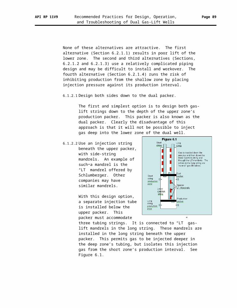
API RP 11V9 Recommended Practices for Design, Operation, Page 89and Troubleshooting of Dual Gas-Lift Wells
If possible, use an automatic control system that can deliver gas at the desired rate and pressure, even in the face of gas-lift system upsets.
7.7 Optimizing dual gas-lift wells
It often happens that people are so delighted when they get a dual gas-lift well lifting successfully from both zones, they don’t attempt to fine tune or optimize the operation. However, just as with a single gas-lift well, there can be significant economic benefits from optimization of the well.
7.7.1 Definition of optimization for dual gas-lift
Optimization of a dual gas-lift well essentially requires separate optimization of both sides of the dual. And, this can be very difficult to achieve. The primary steps are:
Achieve deep, stable lift in both sides of the dual.
Determine the economically optimum injection rate for each side of the dual. See Section 9.1 for a discussion of this.
Devise some practical means to inject the optimum rate (or a rate close to optimum) into each zone.
7.7.2 Determination of optimum injection rate
The normal process to determine the optimum injection rate for each zone is described in Section 9.1. Another way to do this empirically is a multi-rate well test of each zone. A multi-rate test is conducted as follows:
Close in one side of the dual gas-lift well.
Conduct a well test on the other side of the dual.
Conduct the test for long enough to measure the injection rate and associated production rate.
Then change the injection rate and conduct another test, or another segment of the multi-rate test.
Continue this process until three or more data points of production rate vs. injection rate have been determined.
Plot these on a plot of production rate vs. injection rate. This becomes a gas-lift
API RP 11V9 Recommended Practices for Design, Operation, Page 90and Troubleshooting of Dual Gas-Lift Wells
response curve. Use this curve to determine, or estimate the optimum injection rate. See Figure 7.1.
The following point must be made about the optimum injection process. It is normally possible to determine the optimum injection rate for each zone, IF a stable flowing and static pressure survey can be run, or if an accurate multi-rate well test can be conducted. However, it is normally not possible to inject gas into each zone at the optimum rate. There are two reasons for this.
It is very difficult to accurately control the injection rate into both sides of a dual, since one side may take more or less gas than desired.
The amount of gas available for injection into the wells served by the gas-lift
system will almost never be equal to the sum of the optimum rates for each well. So, the available amount of gas must be apportioned or allocated to the wells, with the goal of injecting each well as close to its optimum as possible.
When considering the allocation of gas to a well, it is important to know the range of injection rates – the plus and minus range about the optimum injection rate – that is appropriate. The rate must not be too high as this can be uneconomical and cause heading and other problems. It must not be too low as this can also cause heading and other problems. So, as part of the optimization process, it is important to determine the acceptable range of injection from minimum to maximum.
7.7.3 Gas-lift allocation, staying near optimum
When the optimum injection rates are known for both sides of the dual, two important considerations remain:
Injecting a rate into the well that is not too little, not too much, and close to the sum of the optimum injection rates for the two zones.
Devising a means to assure that the correct amount is injected into each side of the dual.
7.3.7.1 Injecting the desired rate into the well
If the desired injection rate into the well is known, and if there is a way to control the injection rate, this is not difficult
In the ideal situation, the desired injection rate is the sum of the optimum injection rate into the two sides of the dual. If there are both single and dual gas-lift wells being served by a single gas-lift injection system, and if it becomes necessary to adjust the injection rate into some of the wells to keep the system in balance, it may be preferred to adjust the injection into the single wells and hold the dual wells constant.
However, there will be times when it is necessary to adjust the injection rate into the dual well. This can be done as long as the rate is kept
API RP 11V9 Recommended Practices for Design, Operation, Page 91and Troubleshooting of Dual Gas-Lift Wells
below the maximum rate and above the minimum rate as determined in Section 7.7.2.
If there is a flow control capability that is automatically set, the injection rate can be controlled to the desired rate. If the injection rate is controlled manually, the recommended approach is to set the injection rate as close as possible to the sum of the optimum rates for the two sides of the dual and hope for the best when there is an upset to the system.
7.3.7.2 Controlling the desired rate into each side of the dual
While it is possible, and may be relatively easy, to control the desired rate of injection into the well, it can be difficult to assure that the desired rate is injected into each side of the dual. The recommended approach is to design the operating gas-lift valve, orifice, or nozzle venturi orifice to inject the desired rate at the expected condition of injection and production pressures.
This can be difficult to achieve with a gas-lift valve that throttles. It can also be difficult to achieve with a standard, square edge orifice, since the rate can change significantly depending on the upstream and downstream pressures. It can potentially be easier to achieve with a nozzle venturi orifice since it operates in the critical flow regime when the downstream pressure is less than 92% of the upstream pressure. If the upstream pressure is known and the downstream pressure can be kept less than 92% of this amount, the rate through the orifice can be known and controlled.
7.7.4 Recommended practices for optimizing dual gas-lift wells
Determine the economic optimum injection rate for each side of the dual gas-lift well. Do this using the procedures discussed in Section 9.1 or by using a multi-rate well test.
Determine the allowable range of the injection rate around the optimum rate, from minimum to maximum.
Develop a control strategy to allocate gas to each dual well with the objective of keeping the injection rate within the acceptable range for the two sides of the dual
8 Surveillance of Dual Gas-Lift Wells
Surveillance is the process of continually, or at least frequently, checking on the operation of a well to be assured that it is operating correctly. And, if it is not operating properly, it is then important to determine the cause(s) of the problem(s) so it (they) can be addressed. Any problem left undetected and uncorrected can lead to production deferment, wasting of injection gas, and possibly serious damage to the well and even to other wells in the gas-lift system.
A pertinent question is, what does a good, properly performing dual gas-lift well look like? And what are the specific situations (measurements, inferences, etc.) that need to be discerned to detect when a dual gas-lift well is not operating as well as it should?
API RP 11V9 Recommended Practices for Design, Operation, Page 92and Troubleshooting of Dual Gas-Lift Wells
Said another way, if wells are going to be dually completed, and if they are going to be artificially lifted with gas-lift, then every effort should be made to make this both technically and economically successful. And if technical and economic success is desired, what must be monitored, measured, and inferred to detect (and correct) problems so that the operation can be made successful?
The most common dual gas-lift surveillance practices are covered in this Section.
8.1 Wireline operations in gas-lift completions
Side-pocket mandrels and conventional mandrels are built with full-bore tubing ID. This provides the operator the convenience of utilizing conventional slick line and electric line tools as needed. When running wireline tools on wells with side-pocket mandrels, the operator must be aware of the possibility of sitting down on the latch of the gas-lift valve. Deviated wells should be completed with orienting style side-pocket mandrels which have orienting sleeves to align the gas-lift valves with the pockets when running or pulling valves. These orienting sleeves are equipped with tool deflectors that are designed to deflect larger wireline tools away from the latch and allow equipment to by-pass the mandrel without risking damage to the latch. If it is necessary to bypass mandrels with tools that have a smaller diameter than the tool deflector, it must be done with caution to prevent damage to the latch.
8.2 Pressure/temperature surveys
Two of the most useful tools for diagnosing and trouble shooting dual gas-lift completions are pressure and associated temperature surveys. The static bottom-hole pressure survey can identify a potential cross flow problem during gas-lift valve change outs. A flowing pressure/temperature survey can indicate the depths of gas injection on the side of the well in which it is performed, and can also identify leaking gas-lift valves within the gas-lift string. Flowing bottom hole pressure information can help determine the productivity of the well by measuring the amount of pressure drawdown at the perforations.
Some production operators are reluctant to run pressure surveys, especially under flowing conditions. The fear of losing wireline tools in the well and the possibility of losing the well altogether are major concerns. But the information gathered from static and flowing surveys, on both strings, can be priceless when trying to troubleshoot an existing gas-lift design, or in proposing a new string of gas-lift valves.
Detailed recommended practices for running pressure surveys are included in API Recommended Practice 11V5. The primary recommendations are summarized in the next Sections.
8.2.1 Static Bottom-hole Pressure (SBHP) Survey
A static bottom-hole pressure survey is straightforward. The gas-lift injection is stopped and the casing and tubing pressures are allowed to bleed down. The well is shut-in for a predetermined amount of time. The pressure bomb or measuring device is run to the perforations, if possible, and kept on bottom for a predetermined amount of time. Then stops are made coming out of the hole to determine the fluid gradient in the wellbore.
At least four stops, at least 121.6 m (300 feet) apart vertically, should be made when pulling up. This is enough to measure the static pressure gradient, and often it is also enough to determine if there is an oil/water contact in the bottom of the well.
API RP 11V9 Recommended Practices for Design, Operation, Page 93and Troubleshooting of Dual Gas-Lift Wells
Some production operators are uncomfortable with running a pressure measurement device below the end of the tubing, especially for the upper zone of a dual gas-lift well. If the pressure measurement device cannot be run to the mid point of the perforations, the static reservoir pressure can be determined by extrapolating the static pressure profile from the bottom measurement depth down to the mid point of the perforations.
The static pressure gradient can also be extrapolated up hole to determine the height of the static fluid column when the well is off production. This is valuable information to have when the well must be kicked off (restarted) after a period of down time.
8.2.2 Flowing Bottom-hole Pressure (FBHP) Survey
Flowing bottom-hole pressure surveys require more care. In some cases, due to limitations on the length of the wellhead lubricator, the wireline tool string may not be long enough to incorporate enough heavy stem weight to buck the upward flow of the well, if the intent is to survey the well from the surface, with the well flowing.
If this is the case, an alternative approach is to temporarily shut-in the well, run the pressure measuring device to bottom, and then open the well back to production. Once the well has stabilized and is performing normally, stops are made coming out of the well, preferably below and above each gas-lift mandrel. Stops are made below the mandrels, in case a gas-lift valve suddenly opens, allowing a surge of gas into the wellbore and possibly blowing the tool string up the hole. In addition, many production operators are comfortable to also stop the measurement device above each mandrel. A lightening in pressure gradient from below to above a mandrel, and cooling “spikes” in the temperature trend, are indicators that gas is entering at a particular gas-lift mandrel.
If the well must be stopped to run the flowing pressure survey, the static pressure survey (Section 8.1.1) should also be run while the well is stopped, if possible. Also, as indicated in Section 7.5, it can be difficult to restart a dual well and return it to its “normal” operation. Therefore, stopping a dual well should be avoided unless it is absolutely necessary.
When these flowing surveys are taken, it is important to stop the measurement tool at each depth long enough for the temperature device to stabilize to the temperature at each depth. Also, if the well is heading or surging, it is important to stop for at least as long as the period of the pressure fluctuation.
8.2.3 Memory Production Logging Tools
Conventional pressure surveys require that the wireline operator note the time of each wireline stop, so the time can be correlated to the wireline depth, thus providing a graphical representation of depth vs. pressure. The problem with this information is that it only represents an instantaneous pressure at an exact moment in time, at a certain stop depth in the wellbore. What about the pressure information between stop depths? This information is also important during a flowing pressure survey. On a conventional flowing pressure survey, a slugging well may appear to show that every gas-lift valve is opening, as the survey records a gas slug from below as it passes the pressure measurement device as it is recording pressure at a stop just below a gas-lift mandrel.
Since no survey tool can provide a snapshot of pressure information along the entire wellbore at any given instant in time, the next best thing is to be able to
API RP 11V9 Recommended Practices for Design, Operation, Page 94and Troubleshooting of Dual Gas-Lift Wells
have wellbore pressures for the entire length of the wellbore, not just at the stops. Previously this involved expensive electric line surveys; but now a more economical wireline method is being utilized, the memory production logging tool.
This memory tool incorporates a casing collar locator, density, pressure, temperature, and spinner rate tools. Data is stored in the tool’s “memory” and downloaded at the surface after the survey is run. This data is correlated back to measured depth and is presented in an “electric line” log format. Temperature anomalies can be verified with the spinner or density tools, to prove or disprove gas injection at mandrel depths. Slugging can be easily identified and differentiated from mechanical problems (i.e., bad gas-lift valve) or as a result of cross flowing between multiple production layers within the wellbore. The quick response of the tool does not require “stops” within the wellbore. The tool is pulled out of the well at a constant rate.
8.2.4 Recommended practices for running pressure/temperature surveys
Run frequent pressure/temperature surveys.
Run and analyze a flowing pressure/temperature survey at least once per year to evaluate the well’s gas-lift performance. Conduct an accurate well test in association with the survey.
Run a static pressure and an associated flowing bottom-hole pressure survey when the well, or one side of the well, must be closed in for some reason. Use this to evaluate the well’s inflow performance, and to calibrate the vertical two-phase pressure model. Conduct an accurate well test in association with the survey.
Run the surveys following the detailed recommendations in API RP 11V5.
Consider running a memory production logging tool to obtain continuous pressure information across the well’s entire depth, without the need to stop the pressure/temperature measurement device below and above each gas-lift mandrel.
8.3 Using pressure/temperature surveys to evaluate and diagnose dual gas-lift
There are two fundamental reasons for running pressure surveys: (1) to evaluate the well’s productivity, and (2) to diagnose/troubleshoot its gas-lift performance. Flowing surveys with gradient stops are also performed in order to match the wells flowing gradient to a flowing correlation for computer modeling and optimization work.
8.3.1 Determine well’s productivity
The productivity of the well can be described with either a straight line Productivity Index (PI) or by using an Inflow Performance Relationship (IPR) curve. The IPR relationship is the most accurate way of describing the reservoirs feed-in ability but the PI can be sufficient in wells producing above the bubble point pressure, or wells that produce mostly water. Data for developing these are obtained by running bottom hole pressure surveys. When running the flowing pressure survey, special care needs to be taken to insure the well is flowing at its
API RP 11V9 Recommended Practices for Design, Operation, Page 95and Troubleshooting of Dual Gas-Lift Wells
normal stabilized rate. If any wireline work is required to prepare for running the bottom hole pressure (BHP) instruments, it is a good practice to complete this work the day before the survey is run thus allowing the well plenty of stabilization time. When recording the static pressure, the shut-in time must be long enough to record true static conditions of the reservoir. It is important to measure the producing rates of the well while the flowing BHP is being run.
The productivity index (PI) of the well can be calculated by measuring the flowing and static bottom hole pressures with the well on test. A pressure build-up is not required when a PI is to be used to describe the reservoir flow. This makes using the PI approach easier to obtain since accurate pressure buildup surveys in gas-lift wells are difficult to obtain. As long as stabilized conditions exist while measuring the flowing and static pressures, it does not matter which is measured first.
If a more accurate reservoir model is needed, a pressure build-up survey can be conducted on the well so that permeability and skin can be obtained for developing an IPR model. This IPR will be more useful in total well optimization as a more accurate flow rate can be modeled for reservoirs producing below the bubble point. And with a known skin value, the well can be analyzed for stimulation.
Obtaining an accurate pressure buildup in gas-lift wells is difficult since during the initial shut-in some additional gas will be entering the tubing through the operating gas-lift valve and will result in inaccurate early time data. Additional complications to the build-up data will occur if unloading gas-lift valves re-open during the build-up survey. This is a common occurrence in dual wells that are equipped with PPO valves. Since the PPO valves are primarily tubing pressure sensitive, re-opening of the unloading valves can be expected as the tubing pressure is building up. A down-hole shut-in device is recommended to obtain a pressure buildup when PPO valves are installed. This device should be set below all gas-lift mandrels to prevent valve interference during the build-up.
8.3.2 Diagnose/troubleshoot gas-lift performance
To diagnose and troubleshoot gas-lift performance, flowing surveys can be run measuring the well’s flowing pressure and temperature gradient. This can be done with either the pressure/temperature logging tools that take frequent readings while running in the well at a constant speed or by taking gradient stops at predetermined depths while running in the well. No matter which method is chosen, the survey should be run while measuring the production rate and gas injection rate. It is also good practice to monitor the well’s injection pressure and tubing pressure during the procedure so that it can be analyzed for heading. A SCADA graph or two-pen chart recording these parameters during the survey procedure will add confidence to the final diagnosis.
There is some risk in running a wireline tool string in the well while it is producing. To minimize the risk, a tubing or collar stop can be placed at the bottom of the tools string. This will prevent the tool string from falling out the end of the tubing in the event of a lost tool string. A stop should always be run when the survey is being done on the short string of a dual.
API RP 11V9 Recommended Practices for Design, Operation, Page 96and Troubleshooting of Dual Gas-Lift Wells
An anti-blowup tool should also be included in the tool string to prevent the tools from being blown up the hole in the event of high velocity in the flow stream. The highest velocity in the tubing will be near the surface where the pressures are the lowest. Extra attention should be paid to the weight indicator at the shallow locations. If the tools will not freely travel down the well in the shallow areas, the survey should be stopped so that more weight can be added to the tool string. Choking back the well to allow the tool string to fall freely is not recommended. Although choking the well will decrease the velocity of the flow stream it also increases the flowing tubing pressure. This places the well outside of normal flowing conditions and could lead to inaccurate conclusions when evaluating the data.
Flowing surveys may be run using continuous logging tools. This method is ideal for determining points of gas injection and locating leaks in the gas-lift valves or even tubing leaks. A collar locator can be added to the tool string to provide accuracy in the location of any leaks that are found. The best results are obtained when the well is lifting in a stable manner. Since the readings are being recorded at a rapid interval while running in the well, any heading that occurs during the survey can lead to inaccurate results. An added benefit of this method is that cross-flow between dual completions can sometimes be detected. If cross flow is suspected, the survey can be designed specifically to diagnose and locate the depth of the cross flow.
Flowing surveys may be run using gradient stops. Taking gradient stops at pre-determined locations are required when a slow responding pressure or temperature element is being used. The main drawback in using this procedure is that leaks occurring in between gradient stops can go undetected. Using gradient stops is usually the preferred method whenever a well is heading severely and the heading cannot be smoothed out with surface adjustments. When this type of heading is occurring, the time cycle of the heads must be known to design the survey procedure. Each gradient stops is made for the duration of one heading cycle. The pressure and temperature information is then analyzed using minimum, average, and maximum readings at each gradient stop. Analyzing the data from a heading gas-lift well is difficult and an accurate diagnosis of the problem will not always be possible.
8.3.3 Recommended practices for using pressure/temperature surveys
Use pressure/temperature surveys to determine the well’s productivity index or inflow performance relationship.
Use surveys to help diagnose problems with current gas-lift operations.
Understand the different roles and procedures required for these two different types of surveys. Don’t try to use an “inflow” survey to diagnose gas-lift problems, and don’t try to use a diagnostic survey to determine a well’s inflow performance.
8.4 Fluid levels
Use and analysis of the fluid level in the annulus is very common in pumping wells. Since a packer is normally not used in these wells, the fluid level can be used to indicate both the static
API RP 11V9 Recommended Practices for Design, Operation, Page 97and Troubleshooting of Dual Gas-Lift Wells
reservoir pressure when the well is not pumping, and the flowing or operating bottom-hole pressure when the well is pumping.
A production packer, or more than one packer, is used in the vast majority of gas-lift wells. So, the fluid level is not as useful. However, it can still provide some valuable information.
8.4.1 Maximum depth to which well has been unloaded
One important piece of information is the maximum depth to which the well has been unloaded. If there are no leaks between either production tubing string and the annulus, and if the upper dual packer isn’t leaking, the static fluid level provides an indication of the deepest point to which the well has been unloaded, and therefore the bottom of the gas column when the well is on gas-lift.
Hopefully the static fluid level will be at the depth of the bottom gas-lift mandrel in the long string, or the tubing string with the deepest mandrels. If it is not, there may be leak or the well may not have been fully unloaded.
8.4.2 Checking for leaks
If the static fluid level is not at the depth of the deepest mandrel, or at the depth of the deepest “operating” mandrel if the well is not valved all the way to bottom, then there may be a leak. The static fluid level will not define where the leak is, as fluid entering into the annulus from a leak will collect in the deepest part of the annulus. In this case, the fluid level may provide an indication of the amount of fluid that has entered the annulus, but not necessarily where the fluid has come from. To determine this, other analyses will be required. This may be determined by evaluating the sonic pressure trace made by the fluid level detection instrument.
8.4.3 Recommended practices for running, using fluid levels
A fluid level may be determined, using a sonic fluid level detection device, to check if there is a leak from one or both of the tubing strings into the annulus. It will not tell where the leak is, but may indicate how much fluid has leaked into the annulus.
Analysis of the sonic pressure trace may indicate the location of the leak.
8.5 Well tests
There are several options or approaches when conducting well tests on dual gas-lift wells. There are specific objectives for each approach.
8.5.1 Test each well, with the other producing
The normal approach is to test each well (side of the dual gas-lift well) with the other side on production. As stated previously, dual gas-lift wells should only be stopped when absolutely necessary. So, the normal and best approach for normal surveillance is to test each well with the other well on production. This not only minimizes disruptions to each zone; it also provides information on how each side of the dual well normally produces.
API RP 11V9 Recommended Practices for Design, Operation, Page 98and Troubleshooting of Dual Gas-Lift Wells
If a flowing pressure survey is being run to evaluate the current gas-lift performance of a dual gas-lift well, this type of test should be run in conjunction with the pressure survey. The objective of this test and survey is to understand and diagnose the current operation. If problems can be found, there can be an opportunity to correct them.
8.5.2 Test each well, with other well closed in
When information is needed on the productivity of each side of a dual gas-lift well, it may be necessary and prudent to close in the other zone while testing one zone. When the other zone is closed in, the zone being tested can be treated and analyzed essentially as a single string well.
When a well is being tested to determine its productivity, the well test is conducted in conjunction with a static and flowing pressure survey. See Section 8.2. Here, to accurately determine the well’s productivity, it is necessary or at least very desirable, to have the well producing in a stable manner. Sometimes, it may be necessary to take special steps to achieve stability for this test. These steps may include such things as temporarily choking the well, or temporarily increasing the gas-lift injection rate. This process is discussed in detail in API Recommended Practice 11V5.
When a stabilized “well productivity” test is being run, every effort should be made to conduct an accurate well test, with accurate measurements of oil, water, and gas production, and gas-lift injection. With only one side of the dual on production, it is certain that all of the injection gas is going into the well on test. If there are accurate measurements of the injection gas and the total produced gas, the formation gas production rate can be calculated by subtracting the injection gas from the total produced gas. Also, in this case, if an accurate flowing pressure survey is run in conjunction with the well test, the vertical multi-phase pressure model can be calibrated for the conditions of the well. The calibration process is described in API Recommended Practice 11V5.
When there is good information on each zone’s productivity and when the pressure model has been calibrated for both zones, this information can be used to predict the well’s performance under various gas-lift design and operating conditions. Changes to the well’s design and operation can be evaluated and the “best” design and operation can be justified.
8.5.3 Test both wells, with both wells in test separator at same time
A third potential type of well test is to test both sides of a dual well at the same time, in the same well test separator. The only reason for this type of test is to measure the total production rate from the combined zones. This may be necessary if there is reason to expect that the actual total production rate is different than the sum of the tests of the two zones when they are tested separately. If this is the case, this combined test may be necessary to more accurately allocate production to the two sides of the dual well.
API RP 11V9 Recommended Practices for Design, Operation, Page 99and Troubleshooting of Dual Gas-Lift Wells
8.5.4 Recommended practices for conducting, using well tests
Normally conduct a well test of each side of a dual gas-lift well with the other side on production. This is how the well “normally” produces, and it avoids needing to stop the other side of the dual.
When conducting a well analysis pressure/temperature survey (see Section 8.1), close in the side not being tested and conduct an accurate test on the side being analyzed.
If there is concern that the total production from the well may not equal the sum of the tests of each side, test both sides in the same test separator at the same time.
8.6 CO2 tracer
A CO2 tracer survey can be an inexpensive way to evaluate gas-lift performance. It has been demonstrated to work well in single gas-lift wells. Its use in dual wells has not been proven.
A small slug of CO2 is injected into the injection gas stream. The time between when the CO2 is injected and it returns to the surface in the production tubing is measured. By knowing the gas injection rate, pressure, and temperature, and the size of the annulus, the depth of the gas injection ca be determined. Also, multipoint gas injection can be detected.
Potential uses of this technique in dual gas-lift wells are discussed in this Section.
8.6.1 Can use to determine highest injection point
By measuring the time for the CO2 slug to return to the surface, in both zones of the dual, it should be possible to determine the depth of the shallowest injection in both zones.
If the well is operating as designed, these depths of injection should normally be close to the same depth. If injection in one zone is significantly higher than in the other zone, this may indicate a leak or gas-lift valve problem in the zone with the shallow injection.
8.6.2 Can tell if either side is multi-pointing
If either side of the dual is multi-pointing, that is if gas is being injected into the well through more than one gas-lift valve, or through a valve and a leak, this should be readily apparent with the CO2 survey. It may not be possible to accurately determine the depth of the second or subsequent injection points, but at least the existence of multi-pointing should be obvious.
8.6.3 Difficult to determine depth of lower injection point(s)
It may be difficult to determine the depth of lower injection point(s) because the gas velocity in the annulus below the top injection point is not known. This is complicated in a dual gas-lift well, where some of the gas is entering one side of the dual and some is entering the other side.
API RP 11V9 Recommended Practices for Design, Operation, Page 100and Troubleshooting of Dual Gas-Lift Wells
8.6.4 Recommended practices for running, using CO2 tracer surveys
Consider using a CO2 tracer survey, in between pressure/temperature surveys, to detect the depth(s) of gas-lift injection in the two sides of a dual gas-lift well.
8.7 Continuous monitoring and control
Much can go wrong with a dual gas-lift well. And, any time when the well is not performing as desired, with deep, stable, optimum gas-lift on both sides of the dual, production is being deferred, injection gas may be wasted, and upsets may be occurring that can have a negative impact on the well and on other wells in the gas-lift system.
The point has been made earlier that for dual gas-lift to be successful, the well must be operated the way it was designed to be operated. That is, the operating gas-lift injection rate and pressure must be consistent with the way the well and its gas-lift valves are designed to operate. And, it must be controlled to keep it stable, even in the face of various types of gas-lift system upsets. A very clear axiom of control is that for any variable to be correctly controlled, it must be accurately measured first.
This makes a strong argument for continuously monitoring (and measurement) of each dual gas-lift well to detect any operating problems so they can be addressed as rapidly as possible; and to know how it is currently operating, so this can be changed (controlled) if necessary to maintain desired operation. There are various methods for continuous monitoring and control. Some are more expensive initially; some are more expensive and difficult to maintain on a day-to-day basis.
8.7.1 Methods of continuous monitoring
The primary methods of continuous gas-lift monitoring that are covered in this recommended practice are manual methods (not recommended), chart recorders and manual chokes or valves, electronic measurements and flow controllers, and production automation systems. Production automation will be mentioned in this Section but it is covered in more depth in Section 10.
8.7.2 What to monitor
The primary recommendation on “what to monitor” is to monitor just enough for effective surveillance and control. Any monitored item requires that a detection or measurement device be installed, calibrated, maintained, and checked.
Based on years of experience, the minimum items that need to be continuously monitored for effective surveillance and control are:
Gas injection pressure.
Gas injection rate.
Production pressure on both sides of the dual.
The item that needs to be controlled is the gas-lift injection rate.
API RP 11V9 Recommended Practices for Design, Operation, Page 101and Troubleshooting of Dual Gas-Lift Wells
With these items, most dual gas-lift problems can be detected. Further measurements such as well tests, pressure/temperature surveys, CO2 surveys, fluid levels, etc. may be required to fully diagnose the cause of a problem once it is detected, but these items are normally sufficient for routine surveillance.
In some cases, other items may be monitored/measured on a routine basis. Some Production Operators measure:
Gas injection temperature, when this is necessary to compensate the gas injection rate measurement.
Production temperature and use of this as a way to detect changes in liquid production rate.
Production rate of liquid where this can be measured with a multiphase meter or estimated with a technique such as the differential pressure method.
Downhole pressure, temperature, and/or gas injection rate when this is available via a surface-controlled gas-lift valve installation.
Some Production Operators use special devices that are designed to provide gas injection measurement and control in one system. The system includes a method to measure the gas injection pressure, the temperature, and the rate by measuring the differential pressure across a control valve (basically a variable orifice). It contains flow control logic so the injection rate can be maintained to the desired injection rate set point.
In addition to these items on each well, there are certain items that need to be monitored / measured on the gas-lift system. The most important are:
Gas-lift system pressure. An important goal is to maintain the system pressure as constant and stable as possible.
Gas-lift rate available for injection. To keep the gas-lift system stable, the system must be kept in balance. To do this, the total injection rate into all of the gas-lift wells served by the system must be maintained equal to the total source of gas into the system.
8.7.3 Manual methods
The manual method of surveillance is normally based on well tests. If the well test appears normal, the well is assumed to be operating OK. If the well test is abnormal, additional checking may be required to determine the cause(s) of the problem. This method is not recommended, as it does not provide sufficient, timely surveillance of dual gas-lift well performance.
8.7.4 Chart recorders and manual control valves
Chart recorders and manual control valves or orifices have been the normal method for gas-lift monitoring and control for many years. If there is sufficient staff to routinely install, maintain, and analyze / evaluate the information on the
API RP 11V9 Recommended Practices for Design, Operation, Page 102and Troubleshooting of Dual Gas-Lift Wells
charts, and to keep the manual control valves / orifices properly set, this can be acceptable.
However, with chart recorders, it is normally difficult to keep all of the charts functioning properly and to have enough time to routinely analyze them. And with manual control, it is usually not feasible to keep the gas-lift system stable and in balance, since there is not enough time to respond to upsets.
So, if chart recorders and manual control valves / orifices are to be used, the recommended practice is to provide sufficient trained staff to maintain these systems and use their information on a routine basis. If sufficient staff can not be assigned to provide this function, this method is not recommended.
8.7.5 Electronic measurements and flow controllers
The use of electronic measurements and flow controllers is a step up from charts and manual control valves. Here, gas-lift injection rate and pressure, and production pressure can be measured and recorded electronically and can be transmitted into a computer system for analysis.
And, gas-lift injection rate set points can be loaded into a flow controller, so that the desired injection rate can be maintained in the face of system upsets. Of course, if a compressor goes down, more controls are needed to maintain the system pressure. For example, it may be necessary to temporarily close in some wells to avoid “starving” all of the wells.
The limitations of this method are that manual labor is still required to obtain the measurements and enter the gas injection set points.
8.7.6 Production automation systems
The best approach for continuous dual gas-lift monitoring and control is a production automation system. Here, the measurements are made continuously (see Section 8.6.7) and the control set points can be updated remotely by an Operator or automatically by the automation system if / when appropriate.
Production automation systems offer many advantages for effective dual gas-lift surveillance and control. These advantages are defined in detail in Section 10 of this recommended practice.
8.7.7 Optimum monitoring frequency
When dual gas-lift wells are monitored / measured with electronic measurements and/or with a production automation system, the optimum frequency for these measurements is once per minute. This frequency has been determined based on extensive testing of both more and less frequent measurements. If the measurements are taken less frequently, some important gas-lift phenomenon such as heading or multi-pointing may be obscured. If they are taken more frequently, too much data is generated that doesn’t add value. (Note: For intermittent gas-lift it may be necessary to monitor the variables more frequently to optimize the size and period of individual gas-lift injection cycles. However, since intermittent gas-lift is rarely considered with dual gas-lift wells, this is not a major consideration.)
API RP 11V9 Recommended Practices for Design, Operation, Page 103and Troubleshooting of Dual Gas-Lift Wells
8.7.8 Making use of monitored information
A significant problem in many production operations is that there is much more information than can be effectively used. If charts are used on each well, there is a problem of having enough staff time to fully analyze them. This can also be true of electronic data. And electronic monitoring / measurement system can generate so much data that people can’t possibly have enough time to use it.
An effective approach to this is use of “exception” reporting. This can work well with a production automation system if it is programmed to provide this service. The system reviews all of the information and uses it to check for alarm conditions, inefficiencies, etc. It then only reports obvious problems or inefficiencies to the gas-lift staff for further review.
Another important use of monitored information is for checking and calibration of gas-lift models. The production automation system can automatically check measured gas-lift parameters against theoretical values for these parameters as predicted by the gas-lift models. If the measured values match the models, this is well and good. If they don’t match, this can be called to the attention of the gas-lift analyst.
8.7.9 Recommended practices for continuous monitoring
Provide the staff and/or the system(s) to continuously monitor and control each dual gas-lift well.
Unless there is an adequate staff level to provide very frequent monitoring and control with manual means, consider use of electronic monitoring / control and/or production automation systems.
Measure at least the gas-lift injection rate and pressure and the production pressures of both sides of the dual.
When using production automation, measure each variable once per minute.
Generate exception reports so people only need to review problem cases.
9 Diagnosis and Troubleshooting
The purpose of this Section is to provide specific examples and case histories of successful (and unsuccessful) diagnosis and troubleshooting of dual gas-lift operations. The primary "lessons" from this Section are:
If something works for others, it may work for you.
If something does not work, it is necessary to either understand why, or avoid it.
API RP 11V9 Recommended Practices for Design, Operation, Page 104and Troubleshooting of Dual Gas-Lift Wells
9.1 Diagnostic techniques
The process of surveillance (or keeping watch) that is descried in Section 8. is intended to gather pertinent information on dual gas-lift wells. One of the primary goals of this is to find problems with the wells, so these problems can be corrected. There are several diagnostic techniques that can be used to assist in analyzing problems with dual gas-lift wells and troubleshooting these problems to determine their causes. The actual cause(s) of problems must be determined before they can be properly solved.
9.1.1 Library of typical problems
A technique to help determine the cause(s) of problems is to compare appropriate measures of a dual gas-lift well’s current performance with a library of comparable measures taken from wells with typical problems that have been diagnosed and analyzed by experts.
A library is created from typical problem cases from the past that have been collected and analyzed. Normally, these cases are “normalized” in some way so that wells of different depths, tubing sizes, etc. can be compared with the library of cases.
Then, appropriate measures from a current dual gas-lift well are collected, normalized, and compared with the library of cases, and the closest matches are reported.
For a dual gas-lift well, the “appropriate measures” include:
A plot of injection pressure and the two tubing pressures vs. time. These can be on either a circular or a linear chart.
A plot of the flowing pressure surveys for both zones, plotted on the same axis.
There is a very good, free software package available to manage the library and perform the matches. Interested Operating Companies must supply typical problem cases that have been analyzed.
This technique works as follows:
When a new “appropriate measure” is taken (see list above) it is automatically normalized and compared with the cases stored in the library.
The software creates an exception report of the best match(es).
The gas-lift analyst can then focus on these specific problems for more in-depth analysis of the cause(s) of the problems.
9.1.2 Comparison with two-pen charts
For dual gas-lift wells, this comparison actually needs to be made with “three-pen or four-pen” charts (or linear plots of automatically-gathered data) since the information of interest includes the injection pressure, the production pressure from both zones, and possibly also the gas-lift injection rate.
API RP 11V9 Recommended Practices for Design, Operation, Page 105and Troubleshooting of Dual Gas-Lift Wells
Just as with similar plots for single gas-lift wells, there are many typical shapes of these plots that can indicate typical problems including:
Heading, in one zone, the other zone, or both zones Injecting shallow in one zone and deep in the other One side taking all (or most) of the gas Gas freezing And many others
9.1.3 Comparison of flowing pressure surveys
For this comparison to be used for dual gas-lift wells, there must be flowing pressure surveys taken on both sides of the dual. The two surveys are normalized by plotting them on the same pressure/depth axis.
This plot can be compared with cases stored in the library. Just as with the two-pen charts, this can provide valuable clues.
This plot can also provide valuable information on its own, even without use of the library. With these plots, one can usually determine the depth(s) of lift on both sides of the dual. It may also be possible to detect leaks and cross flow between zones.
If the well is stable when the surveys are conducted, these plots can be used to determine the operating (flowing) bottom hole pressure, and to calibrate the mathematical model of the vertical pressure profile.
9.1.4 Measurements of well performance
The desired performance of a dual gas-lift well is to have both zones lifting from deep in the zone, with stable injection and production pressures, and optimum injection rates. In addition, it is desired to have the wells’ inflow performances both known and stable. Therefore, the desired measurements of well performance, that can be determined from the above charts and surveys, are:
9.4.1.1 Gas-lift performance
The depth of injection, and the stability or instability of the well, can be determined by examination and analysis of the “two-pen” charts and the flowing pressure survey.
API RP 11V9 Recommended Practices for Design, Operation, Page 106and Troubleshooting of Dual Gas-Lift Wells
The data from the chart must be analyzed by using a vertical multi-phase pressure profile program and gas-lift valve performance data. This analysis can provide an indication of depth of injection and whether or not the well is stable. Also, it will be clear from the chart if the well is stable or not.
The information from the pressure survey can provide a direct indication of the depth of injection, by noting the depth where the pressure profile changes slope. See Figure 9.1.
The question of optimum injection requires more analysis.
9.4.1.2 Well inflow performance
The well’s inflow performance can be determined by knowing the flowing bottom-hole pressure, the static bottom-hole pressure, and an associated well test. This information can be used to generate an inflow performance relationship (IPR) curve for the well.
This calculation should be performed each time flowing and static pressure surveys are run. The IPR curve from this analysis should be compared with the curve from the previous surveys, to determine if the well’s performance is remaining stable or has changed. See Figure 9.2.
9.4.1.3 Well gas-lift response curve
When an IPR curve has been developed, a well gas-lift response curve can be generated. This is a plot of production rate vs. injection rate. It can be used to determine the optimum injection rate for the well. See Figure 9.3.
9.4.1.4 Optimum injection rate
Once a well’s gas-lift response curve has been generated, the optimum gas-lift injection rate can be determined. It is the injection rate at which the income derived from the addition of one more unit of injection gas is less than to cost of the additional injection. There are existing computer programs to calculate this value.
API RP 11V9 Recommended Practices for Design, Operation, Page 107and Troubleshooting of Dual Gas-Lift Wells
9.1.5 Calibration of gas-lift model
If a flowing pressure survey is measured when the well has stable production, the survey can be used to calibrate the mathematical vertical pressure model for the well. The calibration process is performed by adjusting various immeasurable parameters until the calculated pressure profile closely matches the measured profile. The items most often adjusted to find this match are:
Formation gas production rate Effective tubing diameter Gas-lift injection rate Water production rate Water density
There are existing computer programs to perform this calibration. Once the mathematical vertical pressure model is calibrated for the well’s conditions, it can be used to design and analyze gas-lift performance for the well.
9.1.6 Compare current measurements with calibrated model
When the vertical model has been calibrated, and the gas-lift performance curve has been generated, this provides a benchmark for comparing future measurements.
When new well tests are conducted, the calibrated model can be used to calculate the flowing bottom-hole pressure. With the current well test rates, and the most recent static bottom-hole pressure, a new IPR curve can be calculated and compared with the most recent IPR curve from a full analysis. Deviations can be noted.
Another comparison is to plot the current well test rate and gas-lift injection rate on the gas-lift performance curve. See Figure 9.4. If the point falls on or close to the curve, it can be assumed that the well is still performing as expected. If the point falls far from the curve, and if this is confirmed by a second well test, it can be assumed that the performance of the well has changed and it is time to conduct another flowing/static pressure survey with an associated well test.
This comparison can also indicate how close the current gas-lift injection rate is to the “optimum” injection rate determined previously. If it is not as close as desired, corrective action can be taken.
API RP 11V9 Recommended Practices for Design, Operation, Page 108and Troubleshooting of Dual Gas-Lift Wells
Figure 9.5 is another example of this curve. It shows three different well tests that indicate the well lifting from three different depths. This could possibly occur if the well is tested while it is unloading and actually producing from different depths during the unloading process.
9.1.7 Exception reporting of deviations
If the surveillance and data acquisition is being performed by a production automation system, the system may have the ability to provide exception reports to the gas-lift analysts. The idea of exception reporting is to report only those wells and conditions that require immediate attention. This allows the gas-lift analyst to focus on problems to be solved, and not have to spend time looking for problems.
If there is an exception reporting capability, the following exceptions can be reported, perhaps on a daily basis. When an exception is reported, it may also be possible to present pertinent information. The system may be able to report any well:
That does not appear to be lifting from the deepest possible point. Include a vertical pressure plot to indicate the likely actual depth of injection.
That appears to be unstable. Include a plot of injection and production pressure vs. time to indicate the degree of instability.
Where the apparent inflow performance has changed significantly from the last measurement. Include the most recent IPR plot and the potential change in inflow productivity.
Where the gas-lift performance appears to have changed. Include the most recent gas-lift performance plot, with the current point of production rate vs. injection rate plotted on the same axis.
9.1.8 Recommended practices for selecting dual gas-lift diagnostic techniques
Develop a library of typical dual gas-lift problems, use a software program to compare current cases to those stored in the library, and determine likely causes of problems.
Routinely evaluate “two-pen” charts or plots of injection and production pressures to detect typical dual gas-lift problems.
Carefully compare and evaluate flowing pressure surveys when they are conducted.
Use the pressure surveys to determine the well’s inflow productivity and to calibrate the mathematical model used to calculate the vertical pressure profile.
API RP 11V9 Recommended Practices for Design, Operation, Page 109and Troubleshooting of Dual Gas-Lift Wells
Routinely generate the appropriate measurements of well performance, including the gas-lift performance, the well inflow performance, the gas-lift response curve, and the optimum injection rate.
Use an exception reporting technique to highlight problems that the gas-lift analysts should address.
9.2 Methods to locate communication problems
Proving good tubing integrity should be one of the first steps in troubleshooting dual gas-lift wells since tubing-casing communication problems may be more common in dual wells than in single completions. When one side of the dual has a tubing integrity problem (a leak), both of the reservoirs may be in communication with each other through the production casing. And just as important, troubleshooting tools such as pressure surveys, temperature surveys, and spinner surveys can lead to false interpretations of the data if communication is present but undetected.
In any gas-lift well, communication problems can go undetected for long periods of time since casing pressure may not show the problem if the leak is deep, and other symptoms of communication can take some time to show up. An acoustic sounding device is a necessary tool for determining tubing integrity.
9.2.1 Proving communication
The following procedure can be used to check for possible tubing communication (leak)
Shut in both sides of the dual at the wing valves and allow both tubing pressures to equalize with the casing pressure.
Connect an acoustic sounding device to the casing.
Connect a chart recorder to both tubing strings. A third pen that can record the casing pressure is also helpful.
Bleed the casing pressure down as fast as possible, preferably through a 1.27 cm (½-inch) ball valve.
Monitor the tubing pressures during the bleed down process for any signs of falling pressure.
Monitor the casing fluid level with the acoustic sounding device during the bleed down process.
Communication is recognized by a falling tubing pressure in either string or by a rising casing fluid level. It is important to note that in wells with deep communication below the static tubing fluid level, the tubing pressure can drop somewhat and then return to its original shut in pressure or higher. This is caused by the reservoir feeding in and usually occurs after the casing bleed-down stops.
A drop in tubing pressure identifies a communication problem in that string. Procedures to determine the location of the communication can then begin.
API RP 11V9 Recommended Practices for Design, Operation, Page 110and Troubleshooting of Dual Gas-Lift Wells
Some wells with communication problems may not display a tubing pressure drop when the casing pressure is bled down. This will sometimes occur in wells that have a point of communication below the tubing’s static fluid level. As the casing pressure is bled down, the casing fluid level will rise due to tubing fluid entering the casing annulus at the communication point. High productivity wells will feed fluid into the tubing and through the communication point very quickly resulting in no change in tubing fluid level and no pressure change at the surface. Communication in these wells can only be detected by monitoring the casing fluid level as the casing is bled down.
9.2.2 Methods for Locating Tubing-Casing Communication
9.2.2.1 There are several methods for locating a tubing-casing point of communication or leak.
Tubing caliper survey . This is the only method for locating tubing-casing communication (leak) that will reliably locate more than one hole in the tubing. The caliper survey is the best method for locating holes in the tubing but cannot locate communication occurring in gas-lift mandrels.
Other methods . Other methods of locating the point of tubing-casing communication include the hole finder, ponytail, spinner, and pressure/temperature surveys. These methods involve circulating either liquid or gas through the point of communication and are usually only good for finding one hole. If the tubing has multiple holes, generally the top hole is the only hole that will be located. The advantage in using these methods is the capability of detecting communication at gas-lift mandrels.
Hole finder . This tool can be used for multiple pressure tests in different locations of the tubing without shearing off the tool string. This tool is run to the deepest point to be tested and is anchored with either a collar stop or tubing stop. Sitting down on the tool seals the tool against the tubing wall and the tubing is pressured up for testing. After the tubing is tested, equalization across the tool is achieved with a straight pull. Light jarring will then release the tool and permit it to be moved up hole to the next test depth.
Spinner . The spinner can identify more than one hole provided there is steady flow occurring at each point of communication. A collar locator is usually run with the spinner to more accurately locate the depth.
Ponytail . Generally any strong rope can be frayed and used as a ponytail. One end is frayed and the other end is tied to a light wireline tool string. The tool string is run slowly down hole while circulating gas or pumping water down the tubing and up the casing. The depth of the hole is located when the rope is sucked into the hole and will temporarily hang up the tool string. This method is not as reliable as the hole finder since there are many things that can cause a light tool string to sit down and give a false indication of a hole. Sometimes the circulating rate is not high enough to flow the rope into the hole, thus resulting in no detection of the hole.
Pressure/temperature surveys . Although these are generally run to optimize the gas-lift design, they can also be used to locate a tubing leak if
API RP 11V9 Recommended Practices for Design, Operation, Page 111and Troubleshooting of Dual Gas-Lift Wells
the leak is taking injection during the procedure. A fast responding temperature element is necessary and a collar locator is recommended to pinpoint the holes location.
9.2.3 Recommended practices for locating communication problems
Since communication problems between the annulus of a dual gas-lift well and one or both tubing strings can occur, and since they can go undetected by normal surveillance means, special tests to check for a leak should be run on a prescribed frequency, or whenever a possible communication problem or leak is expected.
9.3 Examples of typical dual gas-lift problems
This Section contains several examples of dual gas-lift problems.
9.3.1 Higher backpressure than the original designed conditions
High wellhead backpressure causes inefficient operation in any gas-lift well but the inefficiency can be greatly magnified in duals, especially when they are equipped with PPO gas-lift valves. Higher tubing backpressure prevents the upper unloading valves from closing or can cause closed valves to re-open. This causes heading and also results in shallow injection points that limit the drawdown of the reservoir. Heading problems are compounded since two production strings share the same casing. Some causes of high backpressure include surface restrictions, long flowlines, small diameter flowlines, emulsions, flowline plugging with paraffin or sand, and over-injection.
9.3.2 Lower injection pressure than the original designed conditions
This is one of the most common causes of inefficiencies in dual gas-lift wells. When one string works with less than the designed injection pressure, that string may take the majority of the injection gas and thus “rob” it from the other side of the dual. When PPO valves are used, the designed injection pressure must be maintained on the casing in order for the gas-lift valves to properly transfer down to the well’s optimum lifting depth. In some cases this problem is a result of under-injection and can be corrected by increasing the gas injection rate. If increasing the injection rate does not raise the injection pressure to the designed conditions, the well should be checked to see if the gas-lift valve port sizes were properly selected. Tubing-casing communication can also cause this problem. If communication is suspected, refer to Section 9.2 for troubleshooting procedures.
In duals that have been equipped with IPO valves, the low casing pressure can be a result of a cooler flowing temperature profile than the designed conditions.
9.3.3 Higher injection pressure than the original designed conditions
When this occurs, both sides of the dual should be tested individually to check each well’s injection rate and make sure that no over-injection is occurring. In dual wells equipped with PPO valves, higher injection pressure is not always a problem since the higher pressure might allow the well to transfer to deeper injection points. This will not
API RP 11V9 Recommended Practices for Design, Operation, Page 112and Troubleshooting of Dual Gas-Lift Wells
result in over-injection since the PPO valve is only slightly affected by the injection pressure.
9.3.4 One string will not take injection gas or takes too little gas
One of the main reasons for one string to not take injection gas is a failed PPO valve, since this type of valve fails in the closed position. But it is important to realize that other factors can cause the operating valve to not be open. Some of the other causes include low injection pressure, a lighter gas gradient in the casing than the design parameters assumed, a heavier unloading fluid gradient than the one assumed, not enough fluid head in the tubing, plugged valves, and tubing plugging off with sand, scale, or paraffin.
9.3.5 One string taking more injection gas than its designed rate
This can be caused by tubing-casing communication, leaking valves, or a gas-lift design that needs to be revised. A tubing integrity test should be run to rule out a communication problem. When the tubing integrity is proven to be good, a flowing survey is usually required to identify the problem. If the well is experiencing problems with heading, attempts to stabilize the flow should be made before running the flowing survey. Shutting in the other side of the dual and/or changing the gas injection rate may help stabilize the production rate.
9.3.6 One string has pressure depleted and is shut-in
The static bottom-hole pressure (SBHP) of the shut-in side should be measured to make sure it is higher than the gas-lift operating pressures. If the SBHP of the shut-in side is lower than the injection pressure of the producing side, shutting in the well at a surface wing valve will result in loosing injection gas into the formation. A plug will need to be set in the depleted side below the bottom gas-lift mandrel to prevent loosing injection gas into the formation.
9.3.7 Tubing-casing communication
Communication is usually recognized due to heading problems and a loss in fluid rate. Duals with a communication problem below the operating valve will sometimes show no initial symptoms. This will not last long since the formation will fill up the casing after each shut-in and this casing fluid will be unloaded through the gas-lift valves when the well is brought back to production. Only after gas-lift valves begin to flow-cut from constantly unloading casing fluid, will the symptoms begin to show up. Procedures for proving and locating communication are provided in Section 9.2.
9.3.8 Wells that produce emulsions
Emulsions that result in higher fluid viscosities will cause a heavier flowing tubing gradient and higher flowing tubing pressures. This will frequently cause heading and reduce the gas-lift efficiency of both sides of the dual. A downhole chemical injection system can be installed to inject an emulsion breaker to control the emulsion down-hole.
If it is not feasible to install this system, the emulsions can sometimes be controlled by injecting an emulsion breaker with the injection gas. Chemical usage will be higher with this method as both sides of the dual will be taking the emulsion breaker with no means of control over the chemical rate of either side. If chemical injection is to be used, the
API RP 11V9 Recommended Practices for Design, Operation, Page 113and Troubleshooting of Dual Gas-Lift Wells
chemical must be tested for compatibility with the packing and o-rings of the gas-lift valves.
9.3.9 Sand production
If a dual well begins to make sand and it is not economically feasible to install sand control, it may be necessary to reduce the well’s flow rate. The production rate of the sand-producing side can be reduced by lifting the well at a shallower point of injection or by lowering the gas injection rate of this side. It is important to note that reducing the gas injection rate of the sand-producer will likely require a valve revision to decrease the port sizes (or chokes) of the gas-lift valves. If the surface injection rate is reduced without making a gas-lift valve revision, the injection rate of both the sand-maker and the sand-free side will likely be reduced. And, with the lower injection rate, heading or pressure surges may occur.
Installing a surface choke to control the sand production should only be considered as a last resort when all other options have failed. A surface choke will affect the operation of the gas-lift valves and can create heading problems in both sides of the dual. If heading is induced with the surface choke, sand problems can be magnified even with lower production rates
9.3.10 Other typical gas-lift problems
There are a number of other typical gas-lift problems that the dual gas-lift diagnostic system should be able to detect. Most of these can be problems either with single or with dual gas-lift wells. These include:
Blowing gas around . This occurs when there is a leak of some nature high in one or both wells. Gas is injected through the leak and recycles up the tubing without performing any actual gas-lift function. This can be detected if the gas-lift injection rate is still normal, or nearly normal, but the injection pressure is very low and the well is no longer producing fluid.
Gas freezing . This occurs when water vapor in the gas freezes at a point of pressure (and temperature) drop. This most often occurs at a control choke or valve, if the gas has not been properly dried by dehydration. This can be detected if the gas-lift injection rate has fallen very low or to zero, the upstream injection line pressure is high, and the downstream wellhead injection pressure is low.
Well heading . This occurs when there is pressure (or rate) fluctuations in the casing annulus and/or the production tubing. Such heading or fluctuations can be especially detrimental in dual wells because instability in one zone can easily cause instability in the other zone. An extreme case of heading may occur when one or both zones of a dual gas-lift well are incapable of maintaining continuous gas-lift and begin to “self intermit.” Heading can be detected by noting periodic fluctuations in injection and/or production pressure.
Well dying or dead . In some cases, a well may be incapable of maintaining gas-lift on a consistent basis and may be either dying (starting to cease production) or already dead (off production). This condition can be detected by very low production pressure.
API RP 11V9 Recommended Practices for Design, Operation, Page 114and Troubleshooting of Dual Gas-Lift Wells
9.3.11 Recommended practices for understanding example problems
Become aware of these potential problems with dual gas-lift, keep a watch for them, and address them quickly if they occur.
10 Automation of Dual Gas-Lift Wells
The following conundrum is difficult to understand. People drill dual wells to save money. And, of course, they are most anxious to effectively and profitably produce both sides of a dual well. However, often when it comes to considering the possibility of automating the operation of duals, people say that they can't afford it because the well isn't worth it. What's wrong with this picture?
The thing that may be wrong is that Operators have had so many problems in successfully operating dual gas-lift wells that they have no confidence that they can do a better job with automation, so why make the investment to try?
The purpose of this Section is to recommend production automation practices, which if followed, can (potentially) go a long way to helping make the operation of dual gas-lift wells become profitable.
10.1 Gas-lift automation logic
There are several effective gas-lift automation systems in use in the world. Some of the key components of these systems include continuous processes to:
Monitor (measure) key well parameters (see Section 10.2).
Monitor (measure) key gas-lift system parameters (see Section 10.2).
Provide surveillance (analysis) of this information to find problems (see Section 9.1).
Report problems to gas-lift analysts on an exception basis (see Section 9.1).
Control gas-lift injection into the wells in a way to keep the gas-lift system in balance and the wells operating as close as possible to their individual optimum points (see Section 10.3).
Integrate gas-lift operations with other field operations such as well testing, production facility operations, etc.
Provide information and training on how to make best use of the automation system to gas-lift operators, technicians, analysts, and engineers.
10.1.1 Recommended practices for automatic logic
Assume that use of a gas-lift automation system will be easily justified on every important dual gas-lift operation. Take the approach that a justification must be prepared to “not” use automation.
Use a proven gas-lift automation system. There is no need to “reinvent the wheel.” There are several acceptable systems available in the industry.
API RP 11V9 Recommended Practices for Design, Operation, Page 115and Troubleshooting of Dual Gas-Lift Wells
Provide enough training to the gas-lift system so they can make effective use of the automation system.
10.2 What to measure
There are a few key measurements that are essential on each gas-lift well, and on the gas-lift system. There are additional optional measurements that may be warranted in some cases. It is recommended to measure these variable once per minute.
10.2.1 Required well measurements
For dual gas-lift automation, the following measurements are necessary on each gas-lift well.
Injection pressure . This is needed to analyze the performance of each zone of the well. The injection pressure at the surface can be used to calculate the pressure in the well, at the depth of each gas-lift mandrel for each side of the dual. If possible, this should be measured at the wellhead, downstream of any obstruction or pressure drop device such as a control valve, orifice meter, etc.
Injection rate . This is needed for analysis and it must be measured so it can be controlled. The gas-lift injection rate will be controlled at the surface to provide the combined rate needed by the two sides of the dual. The rate can be measured with various devices including an orifice meter, turbine meter, etc. This can be measured at the wellhead; or it can be measured at the gas-lift injection manifold if one is being used.
Production pressure on each side of the dual . This is needed for analysis. It can be used to calculate the production pressure in the well, at the depth of each gas-lift mandrel for each side of the dual. If possible, this should be measured at the wellhead, upstream of any obstruction or pressure drop device such as a choke body, control valve, differential pressure device, etc.
10.2.2 Optional well measurements
The following measurements are optional on each gas-lift well.
Injection temperature . In some cases, the injection temperature is needed to compensate the injection flow rate measurement. In other cases, the temperature can be estimated with sufficient accuracy so that a temperature measurement is not required. If the gas injection is being measured and controlled at a gas-lift manifold, one temperature can be used to compensate the measurements into all of the wells.
Production rate . Where it is possible, it can be very advantageous to measure or estimate the production rate of both sides of the dual well. There are various techniques available to give a reasonable estimate of the production rate, at a reasonable cost. One method is the “differential pressure” method. The differential pressure is measured across a small pressure drop device such as a choke body. This, along with the production pressure and the gas-lift injection rate, can be used to estimate the production rate of liquid (oil + water) and gas.
Production temperature . Some production operators like to measure the production temperature and use this to provide an indication of a change in flow rate. If the
API RP 11V9 Recommended Practices for Design, Operation, Page 116and Troubleshooting of Dual Gas-Lift Wells
production temperature rises, this may indicate a higher flow rate. If it falls, this may indicate a lower production rate. If the production temperature is measured, it must be measured in a location that measures the temperature of the fluid and is not affected by the air temperature, the sun light, etc.
Flowline pressure . This value, in conjunction with the pressure at the production manifold, can provide an indication if there is any blockage in the flowline. If this is used, it should be measured downstream of any wellhead pressure drop device.
Production manifold pressure . This value, in conjunction with the flowline pressure at the wellhead, can provide an indication if there is any blockage in the flowline.
10.2.3 Required system measurements
The following measurements are necessary on each gas-lift system.
Total gas-lift flow rate available for gas-lift . This is the total gas flow rate that is available for gas-lift injection into all of the gas-lift wells that are served by the system. Often this can not be determined with one measurement, but must be determined from the sum (or subtraction) of several measurements. For example, it may be necessary to add together the gas from several compressors, and then subtract gas that is used for other purposes such as fuel, sales, burning a flare pilot, etc.
Gas-lift system pressure . This is the pressure of the gas-lift system. If the system is large, it is still necessary to choose one system pressure that is most representative of the pressure in the system. Since this value is so important for control of the system, it may be appropriate to measure two or more pressures and use one or two to back-up the primary pressure measurement.
10.2.4 Optional system measurements
The following measurements are optional on each gas-lift system.
Intermediate gas-lift flow rate measurements . In some large gas-lift distribution systems, there may be several gas-lift manifolds with “master” meters associated with each manifold. If there are, these can be included and used to enhance the accuracy of gas-lift injection measurements. For example, they can be used to help detect a measurement error in one gas-lift injection meter.
Additional flow rate measurements at each compressor . While it is not necessary for the gas-lift system itself, it may be desired to measure the gas flow rate into each gas-lift compressor, the discharge rate, and the recirculation rate, if any. This information can be used to assist in compressor monitoring and control.
System temperature . In some cases, it may be desired to measure the gas-lift system temperature and then use this to compensate gas-lift system flow rate measurements, or flow rate measurements to each well, if these measurements are taken at a gas-lift manifold.
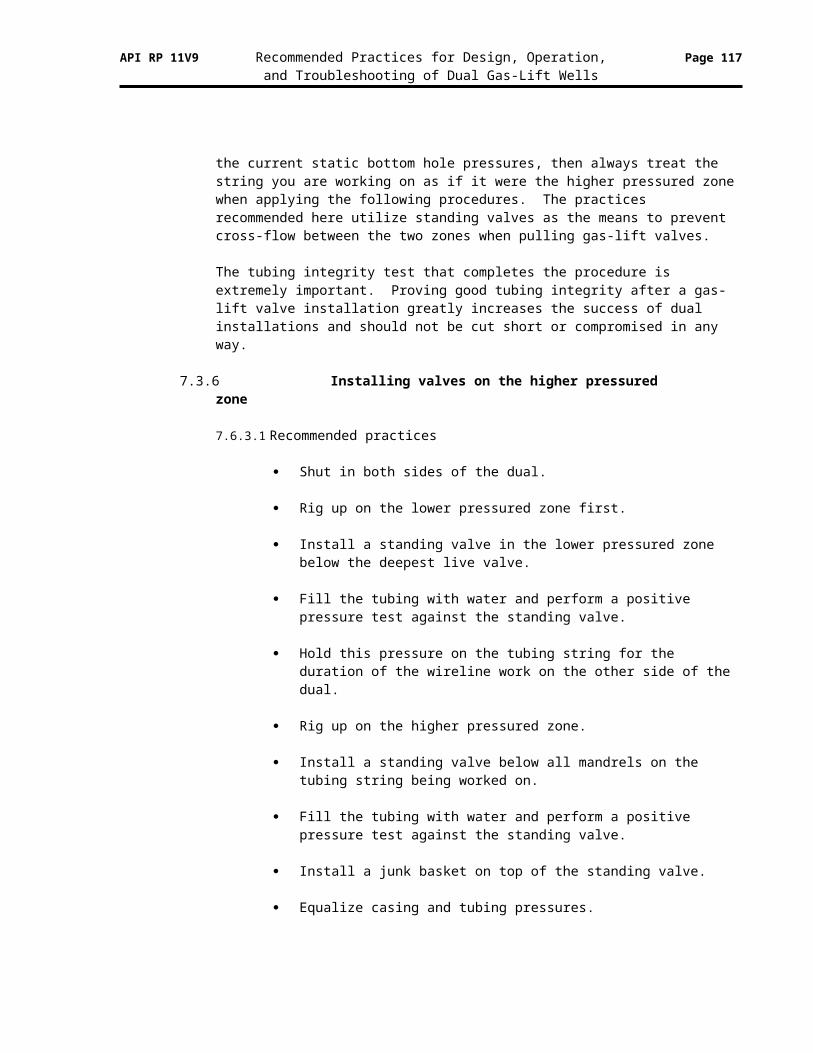
API RP 11V9 Recommended Practices for Design, Operation, Page 117and Troubleshooting of Dual Gas-Lift Wells
10.2.5 Recommended practices for automatic measurements
For each gas-lift well, measure the injection pressure at the wellhead, downstream of any pressure drop device. Measure the injection rate, either at a gas-lift manifold or at the wellhead. Measure the production pressure of each side of the dual at the wellhead, upstream of any pressure drop device.
For each gas-lift system, measure the total flow rate of gas that is available for gas-lift. Measure the gas-lift system pressure at a location that is most representative for the system.
10.3 What to control
There is one essential control for each dual gas-lift well, and two optional controls that may be considered. There are no required controls on the gas-lift system, but some optional controls may be considered
10.3.1 Required well control
For dual gas-lift automation, it is necessary to control the rate of gas-lift injection into each well. This control can be performed at a gas-lift manifold or at the gas-lift wellhead. The injection rate must be sufficient to lift both sides of the dual. The following considerations are important:
The gas-lift injection rate into each dual well should be as close as possible to the sum of the optimum injection rates for both zones.
Because of the difficulty of starting a dual gas-lift well, the injection rate should be held constant as much as possible. If the injection into some of the wells must be adjusted to maintain a balance between supply and demand in the gas-lift system, this adjustment should be made to single gas-lift wells if possible.
If the gas-lift injection rate into a dual gas-lift well must be adjusted, it should be changed as little as possible to maintain injection into both sides of the dual.
10.3.2 Optional well controls
The following controls are optional on each gas-lift well.
Injection pressure . When the injection rate into a dual gas-lift well is controlled to a fixed value, the injection pressure can change. It will change if, for example, the pressure in the gas-lift distribution system changes, or if the conditions in the well change. Because the injection pressure is so important to the operation of the gas-lift valves in the well, some production operators try to maintain the injection pressure within a desired range by using a technique known as pressure override control. With this technique, they control the injection rate, but only within limits. They restrict the range of injection rate control to maintain the injection pressure within prescribed maximum and minimum values. If an injection rate control action would cause the injection pressure to exceed a prescribed high limit or fall below a prescribed low limit,
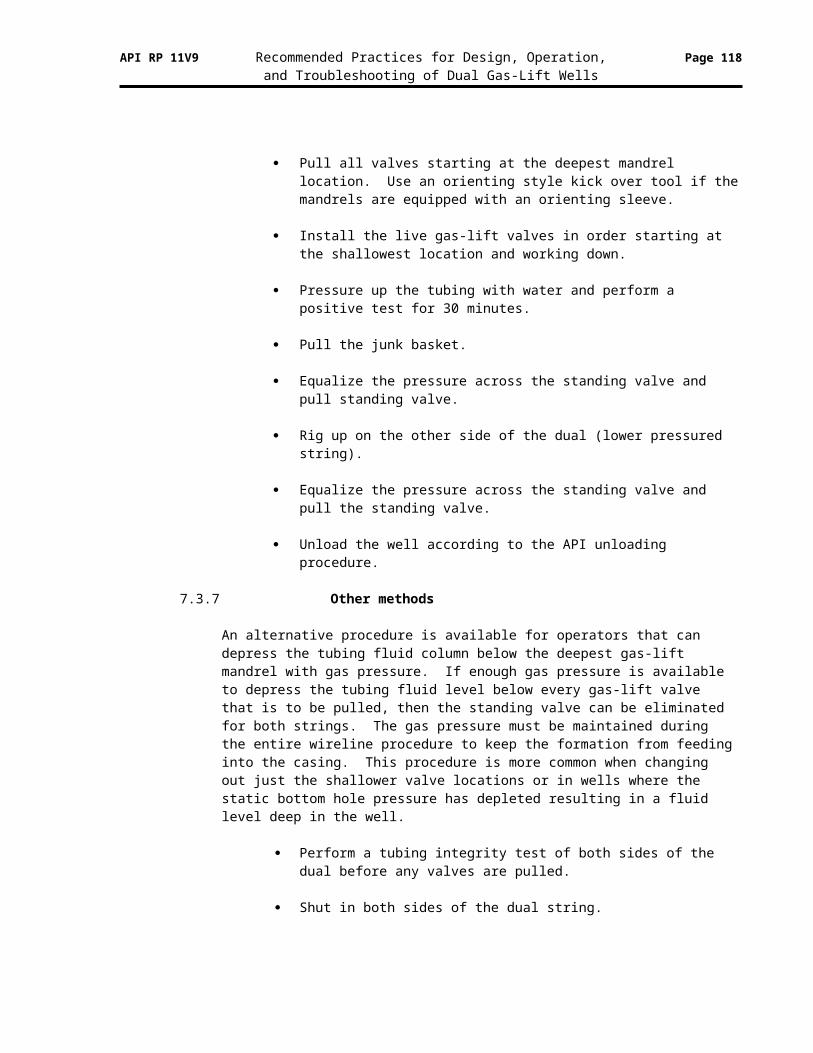
API RP 11V9 Recommended Practices for Design, Operation, Page 118and Troubleshooting of Dual Gas-Lift Wells
they “override” the injection rate control and limit its change to maintain the injection pressure within the desired range.
Production pressure . Some production operators control the production pressure. By making relatively small adjustments to the production pressure (the backpressure on the production string), they attempt to minimize instability on the production side. This is not a widely used technique.
10.3.3 Required system control
There are no required controls on the gas-lift system.
10.3.4 Optional system controls
The following controls are optional on each gas-lift system.
Compressor system . Some production operators place controls on their gas-lift compressors to enhance their operation.
Gas-lift distribution . Some production operators control the distribution of gas-lift gas to various portions of the gas-lift system. For example, this may be used if a compressor plant is compressing gas for use on different offshore platforms.
10.3.5 Recommended practices for automatic controls
Carefully control the gas-lift injection rate into each dual gas-lift well. The objectives of this control should be to: (a) inject as close as possible to the sum of the optimum injection rates for both sides of the dual, (b) keep the injection rate constant to the degree possible, and (c) if the rate must be adjusted, make only small adjustments so injection into both sides of the dual well can be maintained.
10.4 Responding to gas-lift system problems
With a production automation system, it is possible to respond directly to some gas-lift system problems.
10.4.1 Gas-lift system upsets
If an upset occurs in the gas-lift system, due to a compressor shutdown or restart, to a production station trip or restart, or to an upset in another well on the system, the production automation system can rapidly react to keep the system in balance, keep the system pressure (relatively) stable, and keep from allowing upsets in the wells that are being controlled.
As indicated previously, to maintain system balance in the face of a system upset, the injection rates into some (or all) of the wells must be adjusted. If possible, any necessary adjustment should be made to single gas-lift wells that are being served by the gas-lift system. If an adjustment must be made to a dual gas-lift well, it should be kept to the minimum possible change so as to maintain injection into both zones of the dual well.
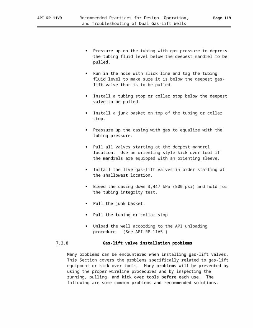
API RP 11V9 Recommended Practices for Design, Operation, Page 119and Troubleshooting of Dual Gas-Lift Wells
10.4.2 Restarting after an upset
If it has been necessary to decrease the gas-lift injection rate into a dual well to the degree that one or both sides of the dual may have stopped producing, the well should be restarted again after the cause of the upset has been corrected using the restart techniques described in Section 7.5.
10.4.3 Controlling the well during well testing
When one or both sides of a dual gas-lift well are being tested, the gas-lift injection rate should be maintained constant in the well, regardless of upsets in the gas-lift distribution system. This is necessary to obtain useful well test information.
10.4.4 Responding to an obvious gas-lift problem in the well
The production automation system will be able to detect many obvious gas-lift problems such as those discussed in Section 9. If, based on the problem detected, it is clear that the well is not producing effectively, injection to the well should be stopped, so as to not waste gas, and the production operator should be alerted immediately.
10.4.5 Recommendations for automatic response to gas-lift system problems
If possible, each dual gas-lift well should be controlled to maintain its desired operation and stability, even in the face of upsets in the gas-lift distribution system. If adjustments must be made to the gas-lift wells in the system, make these to single string gas-lift wells if possible.
If adjustments must be made to dual wells, minimize the degree of adjustment with the goal of maintaining injection into both zones.
If the injection rate into a dual well must be adjusted enough so that one or both sides stop producing, use the procedures of Section 7.5 to restart the well.
11 Special Issues
The purpose of this Section is to address some "special issues" that arise from time to time. The first issue, the co-existence of a flowing and a gas-lift well in the same wellbore, happens frequently. The others happen much less frequently, but they do occur.
11.1 When gas-lift co-exists with a flowing well in the same wellbore
It often occurs that one side of a dual well will require artificial lift, and specifically gas-lift, while the other side of the well continues to flow.
11.1.1 Important considerations
When one side of a dual well is still flowing and the other side requires artificial lift, and specifically gas-lift, the following points should be considered:
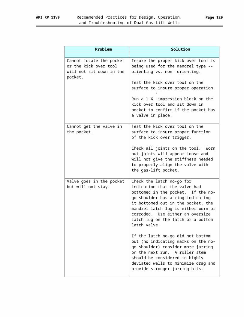
API RP 11V9 Recommended Practices for Design, Operation, Page 120and Troubleshooting of Dual Gas-Lift Wells
11.1.1.1 Mandrel spacing
Check the spacing of the gas-lift mandrels. If it is sufficient for use of IPO gas-lift valves, then use of IPO gas-lift valves is recommended since this will be operated as a single gas-lift well as long as the other side of the dual continues to flow.
11.1.1.2 Unloading
Unloading should be performed just as it would for a single gas-lift well. See API RP 11V5.
11.1.1.3 Kick-off
Kick-off should be performed just as it would for a single gas-lift well.
11.1.1.4 Operation
The well should be operated just as it would for a single gas-lift well.
11.1.1.5 Surveillance and troubleshooting
The well should be monitored, and surveillance and troubleshooting operations should be conducted, just as they would for a single gas-lift well.
11.1.1.6 Special concerns
There are a few special concerns that may be important in this situation.
If the other side of the dual well is flowing at a high rate, it may be hot. This may make the temperature of the gas-lift well higher than it normally might be. This should be considered when designing the gas-lift valves for the well.
When it becomes necessary to lift the side of the dual that was flowing, it may be necessary to redesign the gas-lift valves for the side that has been on gas-lift. It may be necessary to change the type of gas-lift valves that have been used.
11.1.2 Recommended practices when a flowing and gas-lift well co-exist
Unless there is reason that it can’t be done, treat the side with gas-lift as though it is a single gas-lift well, with IPO gas-lift valves and normal single gas-lift unloading, kick-off, and operating procedures.
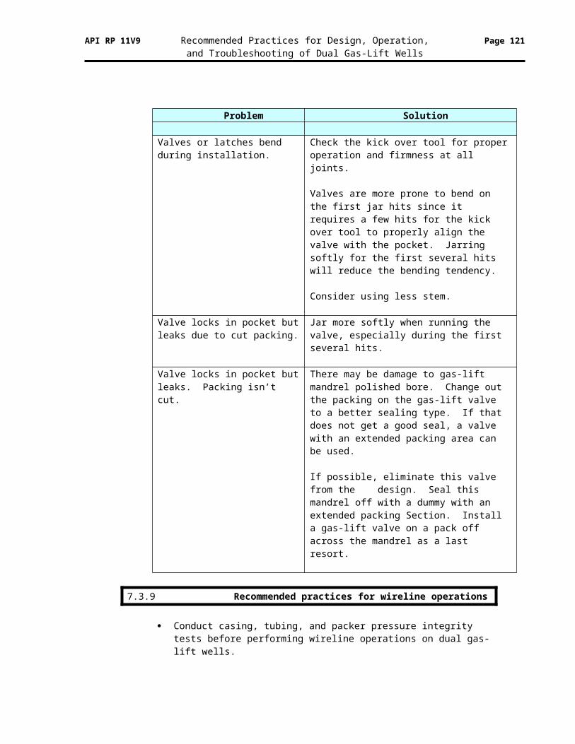
API RP 11V9 Recommended Practices for Design, Operation, Page 121and Troubleshooting of Dual Gas-Lift Wells
11.2 When gas-lift co-exists with a pumping well in the same wellbore
This would be a very unlikely situation. The authors are not aware that this situation has ever been encountered. This would be one for the record books. Be sure to write it up for a Petroleum Industry conference.
11.2.1 Important considerations
If this situation should ever arise, the following issues should be considered:
11.1.2.1 Treat the side on gas-lift as a single gas-lift well
The side of the well that is on gas-lift should be treated as a single gas-lift well. If it is the shallow zone (short string) of the dual, the gas can be injected down the annulus and the well can be unloaded, kicked off, and operated as a single well. If it is the deep zone (long string) of the dual, gas cannot be injected down the annulus, as this would inhibit pumping of the other zone. So, gas would need to be injected down a coiled tubing inside of the main production tubing. Or, a third injection line would be required in the annulus.
11.1.2.2 Pump side that is on pump below packer
Normally a packer is not used in a pumping well, so the gas can flow up the annulus and not through the pump. However, in this case, it might be necessary to pump the well below a packer, and force all of the gas to go through the pump. If the pumping side of the dual is the shallow zone (short string), the tubing could be landed above the dual zone packer and it could be pumped normally. However, if the pumping zone is the deep one (long string), the zone would need to be isolated beneath a packer.
11.1.2.3 Use tubing anchor
It would be essential to use a tubing anchor on the tubing string of the side being pumped, to keep the tubing from moving and rubbing against the tubing of the side on gas-lift.
11.2.2 Recommended practices when a pumping and gas-lift well co-exist
Expect the shallow zone (short string) to operate acceptably as either a gas-lift or a pumping well.
Expect the deep zone (long string) to have problems. There will be difficulty in injecting gas for a gas-lift well, and in pumping beneath a packer for a pumping well.
If this is tried, document the experience for the benefit of others in the industry.
API RP 11V9 Recommended Practices for Design, Operation, Page 122and Troubleshooting of Dual Gas-Lift Wells
11.3 When one or both zones should be intermitted
There are many cases where it is more efficient to intermit a gas-lift well than to attempt continuous gas-lift. However, this is rarely tried in a dual well.
11.3.1 Important considerations
If this situation should arise, the following issues should be considered:
11.1.3.1 Carefully evaluate both sides of the dual gas-lift well
If only one side of the dual should be intermitted, it may be very difficult to effectively lift the other side with continuous gas-lift. Therefore, it may be appropriate to either attempt to intermit both sides, convert the well to a single, or try some other approach, such as pumping one side.
Some other issues to consider are:
It may be ineffective to intermit the lower zone (long string) if the intermitted gas-lift valve must be installed above the dual packer and if this packer is located a long distance above the lower production zone.
A standing valve should be installed in the zone(s) being intermitted to prevent pressure being exerted back on the production formation.
Normally, a carefully designed intermittent operation is preferable to a “self intermitting” well. So, if one or both sides of a dual gas-lift well are self intermitting (heading uncontrollably due to low production rate or low bottom hole pressure), intermittent gas-lift may be more effective than poor continuous gas-lift.
11.1.3.2 If must intermit only one side
If it is essential that one side be intermitted while the other is operated continuously, the following suggestions may be pertinent:
Use “choke” control on the surface, so the injection rate into the annulus is steady.
However, in lieu of a choke, use a flow rate controller or a control valve so the injection rate into the annulus is held constant.
On the continuous gas-lift side of the dual, use a nozzle venturi orifice so the injection rate into it can be held relatively constant.
On the intermittent side of the dual, use a pilot valve (if a 3.81-cm [1.5-inch]) valve can be used) or a large ported IPO valve (if a 2.54-cm [1-inch]) valve must be used). A large ported 2.54-cm (1-inch) IPO valve, with an R value of 0.24, will open on an increase in tubing pressure.
API RP 11V9 Recommended Practices for Design, Operation, Page 123and Troubleshooting of Dual Gas-Lift Wells
11.1.3.3 If must intermit both sides
If both sides of a dual gas-lift well must be intermitted, the recommendations for intermitting one side should be followed. In addition, the two operating gas-lift valves should be set to open at very different pressures, to avoid having both sides of the dual trying to lift at the same time.
11.3.2 Recommended practices when one or both zones should be intermitted
Carefully evaluate both sides of the dual to make certain that intermittent gas-lift of one or both zones is the best approach.
If only one side is to be intermitted, use “choke” control for injection into the annulus and a pilot valve or a large-ported gas-lift valve to minimize casing pressure upsets. Use a nozzle venturi orifice on the continuous side.
If both sides must be intermitted, set the operating valves to open at different pressures so both sides of the dual don’t cycle at the same time. Note that the opening pressures are a function of the injection pressure and the head (level) of liquid above the valves in the tubing.
11.4 When one zone completed with mandrels, one without mandrels
In a few cases, one zone of a dual well may have gas-lift mandrels and the other zone may not. This could occur if the zone without the mandrels was originally designed as a gas well or an injection well and is now to be converted to gas-lift.
11.4.1 Important considerations
If this situation should arise, the following issues should be considered:
11.1.4.1 Carefully evaluate the options for equipping the well for gas-lift
There are basically three options to equip the well for gas-lift: (a) use pack-off gas-lift valves, (b) use coiled tubing with gas-lift mandrels and valves on the coiled tubing, or (c) use coiled tubing with single point injection.
If the well is offshore or in a location where a subsurface safety valve is required, this must be considered.
11.1.4.2 Pack-off valves
The first option is to install pack-off gas-lift valves in the tubing string.
Pack-off gas-lift valves can be installed in the tubing string that doesn’t have gas-lift mandrels.
It is possible to install multiple pack-off valves in one tubing string.
API RP 11V9 Recommended Practices for Design, Operation, Page 124and Troubleshooting of Dual Gas-Lift Wells
They can be used in 6.03-cm (2 3/8-inch) or 7.30 (2 7/8-inch) tubing.
The pack-off valves can be 1.59-cm (5/8-inch) or 2.54-cm (1.0-inch) valves.
The pack-off gas-lift valves can be designed like normal IPO gas-lift valves.
11.1.4.3 Coiled tubing
The second option is to run coiled tubing inside the production tubing, with coiled tubing gas-lift mandrels and valves installed on it. Clearly this will limit the rates that can be produced from the well.
With this option, some method to create a seal between the bottom of the coiled tubing and the production tubing must be implemented.
11.1.4.4 Single point injection
The third option is to run coiled tubing inside the production tubing and either inject gas around the end of the coil and produce up the annulus between the coil and the production tubing, or inject gas down the annulus and produce up the coil.
To consider this option, the surface injection pressure must be high enough to support injection at depth, without the possibility of unloading the well. Or, some other means such as a nitrogen truck must be used to unload the well.
11.1.4.5 Use single point injection on both sides of dual
A fourth option could be to convert both sides of the dual to single point injection and operate both zones with the same surface injection pressure. Again, the issue of unloading and kick-off must be considered.
11.4.2 Recommended practices when one zone doesn’t have mandrels
Consider using pack-off gas-lift valves to equip the side without mandrels for gas-lift.
If this option is not viable for some reason, consider installing coiled tubing in the production tubing and use coiled tubing gas-lift mandrels and valves, or single-point injection near the bottom of the coiled tubing.
11.5 How to transition from flowing to dual gas-lift operation
Pertinent questions are:
When should a flowing well be placed on gas-lift? How should this be done? Are there extra issues if the well is a dual well?
API RP 11V9 Recommended Practices for Design, Operation, Page 125and Troubleshooting of Dual Gas-Lift Wells
11.5.1 When to convert from flowing to gas-lift?
There are several answers to the question of when is the best time to convert a flowing well to gas-lift:
A flowing well should be placed on artificial lift, and specifically on gas-lift, when the production rate of the well can be increased by gas-lift. – The production rate may be declining and it may be possible to arrest
the decline, or perhaps even increase the production rate, with gas-lift.– The well may begin heading and it may be possible to stabilize the well
with gas-lift.– The well may occasionally load up and need to be unloaded or kicked
off with gas-lift.– The well may not return to natural flow when it needs to be stopped.
Gas-lift may be required to reestablish natural flow.
Of course if the well won’t flow any longer, it must be artificially lifted.– If a well dies and won’t flow naturally, it must be placed on gas-lift to
continue production.
And there are other considerations:– If the well under consideration is the first side of the dual to require
gas-lift, it may be possible to treat it like a single gas-lift well. (See Section 11.1)
– If the other side of the dual well is already on gas-lift, this side must be treated as a dual gas-lift well with all of the considerations that this entails.
– The fundamental point is to not hesitate to place a dual well on gas-lift if gas-lift is needed to sustain production. Hopefully, the recommended practices in this document will assist in doing this.
11.5.2 Recommended practices to transition from flowing to dual gas-lift
If a flowing well can no longer produce on its own, or if its production rate can be improved with gas-lift, take the steps necessary to place the well on gas-lift.
Take the necessary steps to lift it effectively. These steps will depend on whether it is the first side of the dual requiring lift, or if the other side of the dual is already on gas-lift.

API RP 11V9 Recommended Practices for Design, Operation, Page 126and Troubleshooting of Dual Gas-Lift Wells
Appendices
Two appendices are included to: (a) show a dual gas-lift mandrel spacing design, and (b) show a dual gas-lift unloading valve design for PPO valves.
12 Dual Gas-Lift Mandrel Spacing Design
This appendix contains an example gas-mandrel spacing for a dual gas-lift well. This example spacing is used in Section 13 (Appendix 2) to perform an example gas-lift valve design for production pressure operated gas-lift valves.
The gas-lift mandrel spacing design is done before and separately from the gas-lift valve design because this is the normal situation. Normally, the mandrels are spaced and installed when the well is completed. The valves are designed when the well must be placed on gas-lift.
12.1 Well descriptionMetric Imperial
Well depth 2,438 m 8,000 ft Geothermal surface temperature 38 oC 100 oF
Casing size 17.78 cm 7.00 inch Tubing size – both zones 6.03 cm 2.375 inch
Depth of lower production zone 2,377 m 7,800 ft Depth of long string production packer 2,347 m 7,700 ft Static reservoir pressure of lower zone 22,063 kPa 3,200 psi Reservoir temperature of lower zone 82 oC 180 oF Flowing surface temperature of lower zone 49 oC 120 oF
Depth of upper production zone 2,011 m 6,500 ft Depth of short string dual zone packer 1,951 m 6,400 ft Static reservoir pressure of upper zone 17,237 kPa 2,500 psi Reservoir temperature of upper zone 66 oC 150 oF Flowing surface temperature of upper zone 43 oC 110 oF
Casing pressure for kick-off 8,274 kPa 1,200 psi Casing pressure for operation 7,929 kPa 1,150 psi Minimum stable tubing pressure 1,034 kPa 150 psi Completion fluid specific gravity 1.05 1.05 Completion fluid gradient 10.28 kPa/m 0.455 psi/ft Injection gas specific gravity 0.65 0.65 Injection gas gradient 0.5311 kPa/m 0.0235 psi/ft
12.2 Design assumptions
Use injection pressure operated (IPO) spacing design. This will provide a conservative mandrel spacing design. That is, they will be closer together than if a production pressure operated (PPO) spacing design were used.
API RP 11V9 Recommended Practices for Design, Operation, Page 127and Troubleshooting of Dual Gas-Lift Wells
Space mandrels based on the long string.
Space the short string mandrels one tubing joint (use 15.2 m [50 ft]) above the lower zone mandrels.
Use the “straight line” design method. This provides a conservative design that makes it easier to unload the well.
Design the mandrels down to just above the dual production packer.
Metric Imperial
Gas-lift mandrels KB KB Gas-lift valves 2.54 cm 1.0 inch Kick-off pressure safety factor 345 kPa 50 psi Kick-off depth safety factor 15.24 m 50 ft Tubing pressure safety factor 345 kPa 50 psi Injection pressure drop between valves 207 kPa 30 psi Minimum spacing between mandrels 91.44 m 300 ft
12.3 Mandrel spacing design for the long string
Manual design method . This design is explained as though it were being performed manually using graph paper. There are several computer programs that can provide the design automatically.
Casing pressure design line . Draw the kick-off casing pressure gradient design line. Draw it from the kick-off pressure at surface, minus the kick-of pressure safety factor, using the injection gas gradient.
Tubing pressure reference line . Draw the straight tubing pressure reference line. Draw it from the tubing pressure at surface, plus the tubing pressure safety factor, plus a value equal to 0.2 times the kick-off injection pressure minus its safety factor, minus the tubing pressure plus its safety factor. Draw it to a value equal to the casing pressure at the depth of the dual zone production packer minus 1379 kPa (200 psi).
In equation form:
Pts = Pt + Pt safety factorPcs = Pc – Pc safety factor
Draw the line from (Pts + 0.2 * (Pcs – Pts )Draw it to Pc @ depth of short string production packer – 1379 kPa (200 psi).
Initial unloading gradient line . Draw the initial unloading gradient line. Draw it from Pts at the surface using the completion fluid pressure gradient.
Intersection of design lines . Find the intersection of initial unloading gradient line and the casing pressure design line.
Depth of top gas-lift mandrel . Find the depth of the top gas-lift mandrel. It is at the intersection found above minus kick-off depth safety factor.
API RP 11V9 Recommended Practices for Design, Operation, Page 128and Troubleshooting of Dual Gas-Lift Wells
Reduced casing pressure design line . Draw the reduced casing pressure design line. This is the new casing pressure design line that is parallel to the original casing pressure line. It is offset from the original casing pressure line by the injection pressure drop between valves.
Next unloading gradient line . Draw the next unloading gradient line from the intersection of the top mandrel depth and the tubing pressure design line. Draw it parallel to the previous unloading gradient line.
Next mandrel depth . Find the intersection of the new unloading gradient line and the new, reduced casing pressure line. This is the depth of the 2nd mandrel.
Continue the process . Continue this process to “work down” until the depth of the upper zone packer, or the minimum spacing between mandrels, is reached.
Add extra mandrels, if pertinent . Add extra mandrels down to packer, if pertinent. Use the minimum spacing between mandrels. The idea here is to space mandrels as close to the packer as is reasonable. Normally do not space a mandrel closer than 30.5 m (100 ft) above the packer.
12.4 Calculated long string mandrel depthsMetric Imperial
1st mandrel 661.4 2170 ft 2nd mandrel 1027.2 3370 ft 3rd mandrel 1322.8 4340 ft 4th mandrel 1539.2 5050 ft 5th mandrel 1697.7 5570 ft 6th mandrel 1828.8 6000 ft 7th mandrel 1920.2 6300 ft
12.5 Calculated short string mandrel depthsMetric Imperial
1st mandrel 646.1 2120 ft 2nd mandrel 1011.9 3320 ft 3rd mandrel 1307.6 4290 ft 4th mandrel 1524.0 5000 ft 5th mandrel 1682.5 5520 ft 6th mandrel 1813.6 5950 ft 7th mandrel 1905.0 6250 ft
Tubing Pressu
re
Kick-Off
Pressure
DesignTubing Pressu
re
DesignCasing Pressu
re
Upper Tubing Design
Line Point
Unloading
Gradient
Lower Tubing Design
Line Point
Casing Pressure
Drop BetweenMandrels
Design
Mandrel
Depths
Upper Zone
Packer Depth
Lower Casing Design
Line Point
Gas-Lift Mandrel Spacing
Design Chart
API RP 11V9 Recommended Practices for Design, Operation, Page 129and Troubleshooting of Dual Gas-Lift Wells
12.6 Graphical design
The chart below shows the above mandrel spacing design on a graphical layout.
API RP 11V9 Recommended Practices for Design, Operation, Page 130and Troubleshooting of Dual Gas-Lift Wells
13 Dual Gas-Lift Unloading Valve Design for PPO Valves
The well parameters given in Section 12 (Appendix 1) are used for the PPO (production pressure operated) gas-lift valve design. The mandrel spacing for the long string will be used in the calculations.
Since PPO valves are mainly controlled by the production pressure in the tubing, it is common to have more than one valve injecting gas while operating under normal conditions. Although multi-point injection is generally considered inefficient, it must be planned for in any PPO design. This design method uses undersized ports in the gas-lift valves to allow for this occurrence. By using undersized ports in the valves, the operator can maintain full operating pressure while injecting in more than one gas-lift valve. The inefficiencies of multi-point injection are usually less important compared to the benefits of the deeper injection point obtained when gas-lifting at the full operating pressure available to the well.
This method applies best to any well that does not operate on the bottom valve. If the well parameters are such that the well will unload and operate on the bottom mandrel then the port sizes of the valves do not need to be undersized.
13.1 Step 1 --- Depth of perforations
Draw a line at the true vertical depth (TVD) of the mid point of the perforations.
13.2 Step 2 --- Injection gas gradient line
Draw the injection gas gradient line for the kickoff and operating pressures from the surface down to the perforations. (Note the kickoff pressure line is only used for location of the top mandrel in the mandrel spacing it will not be used in the calculations but is drawn for reference.)
13.3 Step 3 --- Flowing pressure gradient line
Draw in the flowing pressure gradient for the objective production rate and injection GLR.
13.4 Step 4 --- Transfer pressure for each gas-lift valve
Find the transfer point pressure of each valve (PT). This is done graphically using the slope of the completion fluid gradient. The first valve transfer point will be drawn starting at the intersection of the second valve and the operating pressure gradient. Draw the line up until it intersects the depth of the first mandrel. The pressure at the intersection is the transfer point pressure of the first valve. Continue this for the remaining valves in the well. The bottom valve will not have a transfer point.
13.5 Step 5 --- Safety factor
To insure that any valve is capable of transferring deeper before it closes, a safety factor is subtracted from the transfer point pressure to determine the valves closing pressure. Typically 344.7 Pa (50 psi) is used for this safety factor. PVC = PT – 344.7 kPa (50 psi).
API RP 11V9 Recommended Practices for Design, Operation, Page 131and Troubleshooting of Dual Gas-Lift Wells
13.6 Step 6 --- Gas-lift valve port size
Select the valve’s port size. If valve performance tests are available they can be used for finding the port size needed. When performance tests are not available, the gas passage through a valve can be approximated using 70% of the Thornhill-Craver charts. Once the proper size is found, it is recommended to drop down to the next standard port size. This is necessary since it is common to have more than one PPO valve open while under normal operating conditions. Once the port size of the valve is selected, the R-factor is obtained from the manufacturer of the gas-lift valve.
13.7 Step 7 --- Test rack opening pressure
Calculate test rack opening pressures for each unloading valve. PTRO = PVC / (1 - R)
13.8 Step 8 --- Opening pressure at depth
Calculate the opening pressure (at valve depth) of each unloading valve.OP = (PVC – Pc*R) / (1 - R)
13.9 Step 9 --- Valve or orifice at operating depth
Select either an IPO valve or an orifice for the bottom valve location. If an IPO valve is selected it should be flagged at 689.5 kPa (100 psi) less than the operating pressure. IPO valve calculations are used to calculate the test rack pressure of the valve.
API RP 11V9 Recommended Practices for Design, Operation, Page 132and Troubleshooting of Dual Gas-Lift Wells
13.10 Graphical method for designing PPO gas-lift valves
X = Valve Closing Pressure (PVC)
Tubing Pressure at Transfer Point (PT)
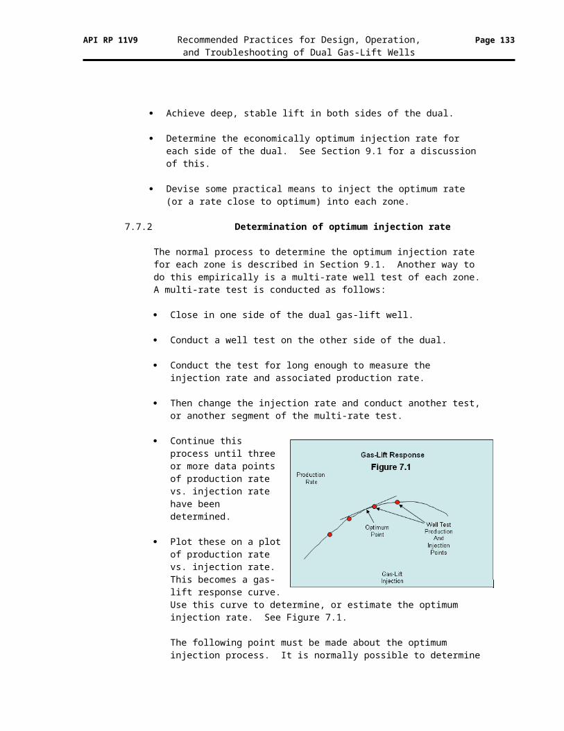
API RP 11V9 Recommended Practices for Design, Operation, Page 133and Troubleshooting of Dual Gas-Lift Wells
13.11 Valve calculations for PPO gas-lift valves
Note. The variables in this table are shown in Imperial units. They can also be produced in Metric units.
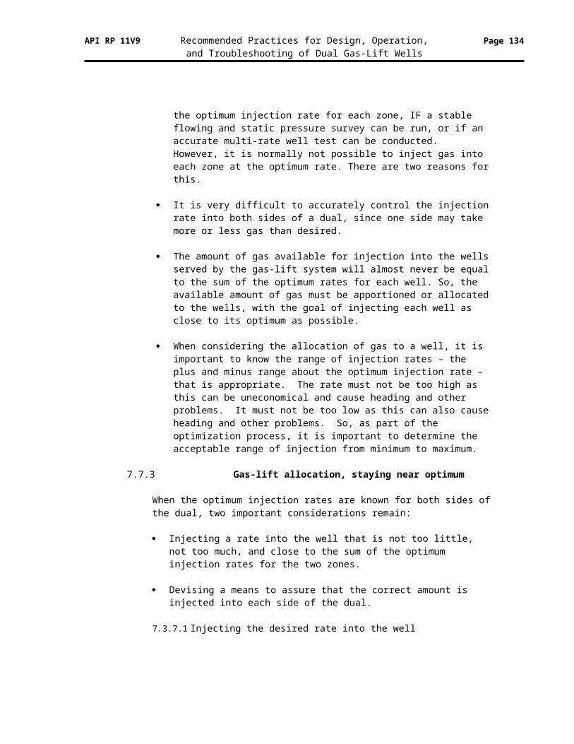
API RP 11V9 Recommended Practices for Design, Operation, Page 134and Troubleshooting of Dual Gas-Lift Wells


![[XLS]azmariner.files.wordpress.com · Web viewPressure testing tool for piston Work table for stuffing box O ring & backup ring Spacer block Lifting tool for connecting rod Lifting](https://img.pdfslide.us/doc/110x75/5b0592457f8b9a58148b8b28/xls-viewpressure-testing-tool-for-piston-work-table-for-stuffing-box-o-ring-backup.jpg)


![[PPT]Canning - National Center for Home Food Preservationnchfp.uga.edu/multimedia/slide_shows/CanLowAcid_web08.ppt · Web viewPressure Canning & Canning Low-Acid Foods at Home This](https://img.pdfslide.us/doc/110x75/5ad21b467f8b9a0f198c0c9c/pptcanning-national-center-for-home-food-viewpressure-canning-canning-low-acid.jpg)