Embed Size (px)
Citation preview
Subject to change without prior notice [email protected]
www.acs.com.hk
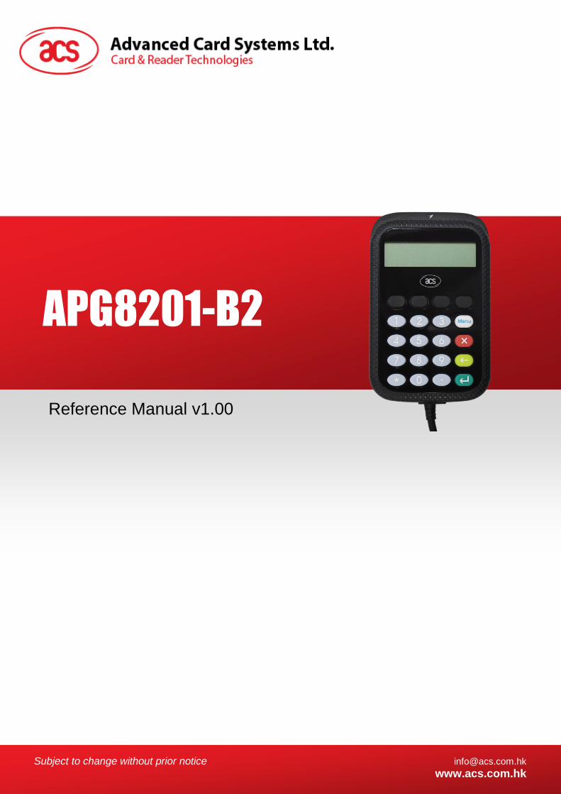
Reference Manual v1.00
APG8201-B2

APG8201-B2 – Reference Manual [email protected]
Version 1.00 www.acs.com.hk
Page 2 of 48
www.acs.com.hk
Revision History
Release Date Revision Description Version Number
2018-06-25 ● Initial Release 1.00
APG8201-B2 – Reference Manual [email protected]
Version 1.00 www.acs.com.hk
Page 3 of 48
www.acs.com.hk
Table of Contents
1.0. Introduction ............................................................................................................. 5
2.0. Features ................................................................................................................... 6
3.0. Supported Card Types ............................................................................................ 7
4.0. Smart Card Interface ............................................................................................... 8
5.0. Card Type Selection ................................................................................................ 9
6.0. USB Interface ......................................................................................................... 10
7.0. USB Communication Protocol (CCID) .................................................................. 11
7.1. PC to Reader ....................................................................................................................... 11 7.1.1. PC_to_RDR_IccPowerOn ........................................................................................... 11 7.1.2. PC_to_RDR_IccPowerOff ........................................................................................... 11 7.1.3. PC_to_RDR_XfrBlock ................................................................................................. 12 7.1.4. PC_to_RDR_GetParameters ...................................................................................... 12 7.1.5. PC_to_RDR_ResetParameters .................................................................................. 12 7.1.6. PC_to_RDR_SetParameters ...................................................................................... 13 7.1.7. PC_to_RDR_Escape .................................................................................................. 15 7.1.8. PC_to_RDR_Secure ................................................................................................... 19
7.2. Reader to PC ....................................................................................................................... 23 7.2.1. RDR_to_PC_DataBlock .............................................................................................. 23 7.2.2. RDR_to_PC_SlotStatus .............................................................................................. 23 7.2.3. RDR_to_PC_Parameters ............................................................................................ 24 7.2.4. RDR_to_PC_Escape .................................................................................................. 25 7.2.5. RDR_to_PC_NotifySlotChange .................................................................................. 29 7.2.6. RDR_to_PC_HardwareError ....................................................................................... 29
8.0. PC-linked Operation Mode .................................................................................... 30
8.1. SCardConnect API .............................................................................................................. 30 8.2. SCardTransmit API .............................................................................................................. 30 8.3. SCardControl API ................................................................................................................ 30 8.4. SECURE PIN VERIFY ......................................................................................................... 30 8.5. SECURE PIN MODIFY ........................................................................................................ 31 8.6. Escape Commands ............................................................................................................. 32 8.7. Get Firmware Version .......................................................................................................... 32 8.8. Display LCD Message ......................................................................................................... 32 8.9. Read Key ............................................................................................................................. 32 8.10. Write Display ........................................................................................................................ 32 8.11. Buzzer Beep ........................................................................................................................ 32 8.12. Get Key ................................................................................................................................ 32
9.0. Device Control ....................................................................................................... 33
9.1. Operation Flow (PC/SC 2.0 Part 10) ................................................................................... 33 9.2. Specific ScardControl .......................................................................................................... 34 9.3. Smart Card Device IOCTLs ................................................................................................. 34
9.3.1. CM_IOCTL_GET_FEATURE_REQUEST .................................................................. 34 9.3.2. FEATURE_VERIFY_PIN_DIRECT ............................................................................. 35 9.3.3. FEATURE_MODIFY_PIN_DIRECT ............................................................................ 36 9.3.4. FEATURE_IFD_PIN_PROP ....................................................................................... 38 9.3.5. IOCTL_SMARTCARD_GET_FIRMWARE_VERSION ............................................... 39 9.3.6. IOCTL_SMARTCARD_DISPLAY_LCD_MESSAGE .................................................. 40 9.3.7. IOCTL_SMARTCARD_READ_KEY ........................................................................... 41 9.3.8. FEATURE_IFD_DISPLAY_PROPERTIES ................................................................. 42 9.3.9. FEATURE_WRITE_DISPLAY .................................................................................... 42 9.3.10. FEATURE_GET_KEY ................................................................................................. 43

APG8201-B2 – Reference Manual [email protected]
Version 1.00 www.acs.com.hk
Page 4 of 48
www.acs.com.hk
Appendix A. Set bKeyReturnCondition ........................................................................ 44
Appendix B. Response Error Codes ............................................................................. 45
Appendix C. bmFormatString Description .................................................................... 46
Appendix D. bmPINBlockString Description ................................................................ 47
Appendix E. bmPINLength Format ................................................................................ 48
List of Figures
Figure 1 : Operation Flowchart ............................................................................................................. 33
List of Tables
Table 1 : ReaderOptions Bit Structure .................................................................................................. 19

APG8201-B2 – Reference Manual [email protected]
Version 1.00 www.acs.com.hk
Page 5 of 48
www.acs.com.hk
1.0. Introduction
The APG8201-B2 is a portable and hand-held smart card device which supports PC-linked and standalone mode to perform various authentication applications. It features a built-in PIN-pad and a graphical LCD that supports multiple languages and alpha-numeric characters. APG8201-B2 supports Secure PIN Entry (SPE) that protects every PIN code from security attacks by using an authentication process within the device.

APG8201-B2 – Reference Manual [email protected]
Version 1.00 www.acs.com.hk
Page 6 of 48
www.acs.com.hk
2.0. Features
● USB Full Speed Interface
● Plug and Play – CCID support brings utmost mobility
● USB Type A Connector
● Smart Card Reader:
o Supports full-sized microprocessor cards (T=0, T=1 Protocols)
o Supports ISO 7816 Class A cards
o Allows semi-insertion of cards
o Short Circuit Protection
● Application Programming Interface:
o Supports PC/SC
o Supports SPE
o Supports PPS (Protocols and Parameters Selection)
● Built-in Peripherals:
o Dot Matrix LCD
o LCD Resolution: 96 × 16 pixels
o LCD Number of characters: 16 characters × 2 lines
o Monotone buzzer
o Durable tactile keypad with 20 silicone rubber keys
o Key symbol on LCD to recognize SPE mode
● Supports Android™ 3.1 and later1
● Compliant with the following standards:
o ISO 7816
o PC/SC
o PC/SC 2.0 Part 10 – Secure PIN Entry
o CCID
o CE
o FCC
o RoHS 2
o Microsoft® WHQL
1 Uses an ACS-defined Android Library
APG8201-B2 – Reference Manual [email protected]
Version 1.00 www.acs.com.hk
Page 7 of 48
www.acs.com.hk
3.0. Supported Card Types
The APG8201-B2 operates on MCU cards Class A (5 V) with T=0 and T=1 protocol in its main card slot. It also supports EEPROM microcontroller-based cards with internal programming voltage (VPP) generation and the following programming parameters transmitted in the ATR:
PI1= 0 or 5
I = 25 or 50
The APG8201-B2 can automatically perform the Protocol and Parameters Selection (PPS) in standalone mode or can manually perform PPS in USB connected mode.
When the card ATR indicates the specific operation mode (TA2 present; bit b5 of TA2 must be 0) and when that particular mode is not supported by the APG8201-B2, the reader will reset the card to set it to negotiable mode. If the card cannot be set to negotiable mode, the reader will reject the card.
When the card ATR indicates the negotiable mode (TA2 not present) and communication parameters other than the default parameters, the APG8201-B2 will execute the PPS and try to use the communication parameters that the card suggested in its ATR. If the card does not accept the PPS, the reader will use the default parameters (F=372, D=1).
For the meaning of the aforementioned parameters, please refer to ISO 7816-3.

APG8201-B2 – Reference Manual [email protected]
Version 1.00 www.acs.com.hk
Page 8 of 48
www.acs.com.hk
4.0. Smart Card Interface
The interface between the APG8201-B2 and the inserted smart card follows the specification of ISO 7816 Part 2 and 3 with certain restrictions and enhancements to increase the practical functionality of the APG8201-B2:
Smart Card Power Supply VCC (C1)
o The current consumption of the inserted card must not be larger than 54 mA
Programming Voltage VPP(C6)
o The VPP pin is left unconnected
Reset Signal (C2)
o Refer to EMV Version 2000 Book1
Clock Signal (C3)
o Refer to EMV Version 2000 Book1
Ground (C5)
o Refer to EMV Version 2000 Book1
I/O Data Input and output (C7)
o Refer to EMV Version 2000 Book1

APG8201-B2 – Reference Manual [email protected]
Version 1.00 www.acs.com.hk
Page 9 of 48
www.acs.com.hk
5.0. Card Type Selection
The controlling computer always needs to select the card type through the proper command sent to the APG8201-B2 prior to activating the inserted card. For MCU-based cards, the reader allows to select the preferred protocol, T=0 or T=1. However, this selection is only accepted and carried out by the reader through the PPS when the card inserted in the reader supports both protocol types. Whenever an MCU-based card supports only one protocol type, T=0 or T=1, the reader automatically uses that protocol type, regardless of the protocol type selected by the application.
APG8201-B2 – Reference Manual [email protected]
Version 1.00 www.acs.com.hk
Page 10 of 48
www.acs.com.hk
6.0. USB Interface
The APG8201-B2 is connected to a computer through a USB, as specified in the USB Specification 2.0, working in full speed mode, i.e. 12 Mbps. In order for the APG8201-B2 to function properly through USB interface, either ACS proprietary device driver or ACS PC/SC device driver has to be installed.
APG8201-B2 – Reference Manual [email protected]
Version 1.00 www.acs.com.hk
Page 11 of 48
www.acs.com.hk
7.0. USB Communication Protocol (CCID)
APG8201-B2 shall establish an interface to the host through the USB connection. A specification, namely CCID, has been released within the industry defining such a protocol for the USB chip-card interface devices. CCID covers all the protocols required for operating smart cards and PIN. The configurations and usage of USB endpoints on APG8201-B2 shall follow the CCID specification.
There are several essential CCID command protocols that APG8201-B2 needs to handle which are enumerated in the succeeding sections.
7.1. PC to Reader
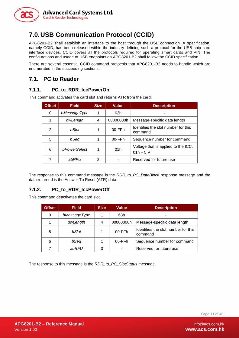
7.1.1. PC_to_RDR_IccPowerOn
This command activates the card slot and returns ATR from the card.
Offset Field Size Value Description
0 bMessageType 1 62h -
1 dwLength 4 00000000h Message-specific data length
2 bSlot 1 00-FFh Identifies the slot number for this command
5 bSeq 1 00-FFh Sequence number for command
6 bPowerSelect 1 01h Voltage that is applied to the ICC:
01h – 5 V
7 abRFU 2 - Reserved for future use
The response to this command message is the RDR_to_PC_DataBlock response message and the data returned is the Answer To Reset (ATR) data.
7.1.2. PC_to_RDR_IccPowerOff
This command deactivates the card slot.
Offset Field Size Value Description
0 bMessageType 1 63h -
1 dwLength 4 00000000h Message-specific data length
5 bSlot 1 00-FFh Identifies the slot number for this command
6 bSeq 1 00-FFh Sequence number for command
7 abRFU 3 - Reserved for future use
The response to this message is the RDR_to_PC_SlotStatus message.
APG8201-B2 – Reference Manual [email protected]
Version 1.00 www.acs.com.hk
Page 12 of 48
www.acs.com.hk
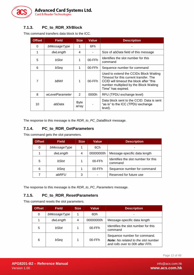
7.1.3. PC_to_RDR_XfrBlock
This command transfers data block to the ICC.
Offset Field Size Value Description
0 bMessageType 1 6Fh -
1 dwLength 4 - Size of abData field of this message
5 bSlot 1 00-FFh Identifies the slot number for this command
6 bSeq 1 00-FFh Sequence number for command
7 bBWI 1 00-FFh
Used to extend the CCIDs Block Waiting Timeout for this current transfer. The CCID will timeout the block after “this number multiplied by the Block Waiting Time” has expired.
8 wLevelParameter 2 0000h RFU (TPDU exchange level)
10 abData Byte array
- Data block sent to the CCID. Data is sent “as is” to the ICC (TPDU exchange level).
The response to this message is the RDR_to_PC_DataBlock message.
7.1.4. PC_to_RDR_GetParameters
This command gets the slot parameters.
Offset Field Size Value Description
0 bMessageType 1 6Ch -
1 dwLength 4 00000000h Message-specific data length
5 bSlot 1 00-FFh Identifies the slot number for this command
6 bSeq 1 00-FFh Sequence number for command
7 abRFU 3 - Reserved for future use
The response to this message is the RDR_to_PC_Parameters message.
7.1.5. PC_to_RDR_ResetParameters
This command resets the slot parameters.
Offset Field Size Value Description
0 bMessageType 1 6Dh -
1 dwLength 4 00000000h Message-specific data length
5 bSlot 1 00-FFh Identifies the slot number for this command
6 bSeq 1 00-FFh
Sequence number for command.
Note: No related to the slot number and rolls over to 00h after FFh.

APG8201-B2 – Reference Manual [email protected]
Version 1.00 www.acs.com.hk
Page 13 of 48
www.acs.com.hk
Offset Field Size Value Description
7 abRFU 3 - Reserved for future use
The response to this message is the RDR_to_PC_Parameters message.
7.1.6. PC_to_RDR_SetParameters
This command sets the slot parameters.
Offset Field Size Value Description
0 bMessageType 1 61h -
1 dwLength 4 - Size of abProtocolDataStructure field of this message
5 bSlot 1 00-FFh
Identifies the slot number for this command
6 bSeq 1 00-FFh
Sequence number for command
7 bProtocolNum 1 00h, 01h
Specifies what protocol data structure follows.
00h = Structure for protocol T=0
01h = Structure for protocol T=1
The following values are reserved for future use:
80h = Structure for 2-wire protocol
81h = Structure for 3-wire protocol
82h = Structure for I2C protocol
8 abRFU 2 - Reserved for future use
10 abProtocolDataStructure Byte array
- Protocol Data Structure
Protocol Data Structure for Protocol T=0 (dwLength=00000005h)
Offset Field Size Value Description
10 bmFindexDindex 1 -
B7-4 – FI – Index into the table 7 in ISO/IEC 7816-3:1997 selecting a clock rate conversion factor
B3-0 – DI - Index into the table 8 in
ISO/IEC 7816-3:1997 selecting a baud rate conversion factor
11 bmTCCKST0 1 00h,
02h
B0 – 0b, B7-2 – 000000b
B1 – Convention used (b1=0 for direct, b1=1 for inverse)
Note: The CCID ignores this bit.
12 bGuardTimeT0 1 00-FFh Extra guardtime between two characters. Add 0 to 254 etu to the normal guardtime of 12etu. FFh is the same as 00h.
13 bWaitingIntegerT0 1 00-FFh WI for T=0 used to define WWT

APG8201-B2 – Reference Manual [email protected]
Version 1.00 www.acs.com.hk
Page 14 of 48
www.acs.com.hk
Offset Field Size Value Description
14 bClockStop 1 00-03h
ICC Clock Stop Support
00h = Stopping the Clock is not allowed
01h = Stop with Clock signal Low
02h = Stop with Clock signal High
03h = Stop with Clock either High or Low
The response to this message is the RDR_to_PC_Parameters message.
Protocol Data Structure for Protocol T=1 (dwLength=00000007h)
Offset Field Size Value Description
10 bmFindexDindex 1 -
B7-4 – FI – Index into the table 7 in ISO/IEC 7816-3:1997 selecting a clock rate conversion factor
B3-0 – DI - Index into the table 8 in
ISO/IEC 7816-3:1997 selecting a baud rate conversion factor
11 bmTCCKST1 1
10h,
11h,
12h,
13h
B7-2 – 000100b
B0 – Checksum type (b0=0 for LRC, b0=1 for CRC
B1 – Convention used (b1=0 for direct, b1=1 for inverse)
Note: The CCID ignores this bit.
12 bGuardTimeT1 1 00-FFh Extra guardtime (0 to 254 etu between two characters). If value is FFh, then guardtime is reduced by 1 etu.
13 bWaitingIntegerT1 1 00-9Fh B7-4 = BWI values 0-9 valid
B3-0 = CWI values 0-Fh valid
14 bClockStop 1 00-03h
ICC Clock Stop Support:
00h = Stopping the Clock is not allowed
01h = Stop with Clock signal Low
02h = Stop with Clock signal High
03h = Stop with Clock either High or Low
15 bIFSC 1 00-FEh Size of negotiated IFSC
16 bNadValue 1 - Value = 00h if CCID doesn't support a value other then the default value
The response to this message is the RDR_to_PC_Parameters message.

APG8201-B2 – Reference Manual [email protected]
Version 1.00 www.acs.com.hk
Page 15 of 48
www.acs.com.hk
7.1.7. PC_to_RDR_Escape
This command defines and access extended features.
Offset Field Size Value Description
0 bMessageType 1 6Bh -
1 dwLength 4 00000000h Size of abData field of this message
5 bSlot 1 00-FFh Identifies the slot number for this command
6 bSeq 1 00-FFh Sequence number for command
7 abRFU 3 - Reserved for future use
10 abData Byte array
- Data block sent to the CCID
7.1.7.1. Get Firmware Version
Offset Field Size Value Description
10 bcmdCode 1 04h -
11 wcmdLength 2 0000h -
13 abRFU 2 - Reserved for future use
Example:
bSendBuffer[0]=04h;
bSendBuffer[1]=00h;
bSendBuffer[2]=00h;
bSendBuffer[3]=00h;
bSendBuffer[4]=00h;
dwSendBufferLen=05h
SCARDStatus = SCardControl( hSAM, SCARD_CTL_CODE(3500), bSendBuffer, dwSendBufferLen, bRecvBuffer, dwRecvBufferLen, &dwRecvBufferLen);
7.1.7.2. Display LCD Message
Offset Field Size Value Description
10 bcmdCode 1 05h -
11 wcmdLength 2 0020h -
13 abRFU 2 - Reserved for future use
15 abData 20 - Data from PC keyboard to show on the LCD
Example:
bSendBuffer[0]=05h;
bSendBuffer[1]=00h;

APG8201-B2 – Reference Manual [email protected]
Version 1.00 www.acs.com.hk
Page 16 of 48
www.acs.com.hk
bSendBuffer[2]=20h;
bSendBuffer[3]=00h;
bSendBuffer[4]=00h;
bSendBuffer[abData]=(31 32 33 20 20 20 20 20 … 20h)
dwSendBufferLen=25h
SCARDStatus = SCardControl( hSAM, SCARD_CTL_CODE(3500), bSendBuffer, dwSendBufferLen, bRecvBuffer, dwRecvBufferLen, &dwRecvBufferLen);
7.1.7.3. Read Key
Offset Field Size Value Description
10 bcmdCode 1 06h -
11 wcmdLength 2 0006h -
13 abRFU 2 - Reserved for future use
15 timeout 1 00h -
16 PinLength 2 XXYYh XXh: PIN Max length
YYh: PIN Min length
18 KeyReturnCondition 1 -
The value is a bit wise OR operation.
01: Max size reached
02: Key Enter pressed
04: Timeout occurred
08: Key Cancel pressed
19 StartPosition 1 -
Bit7-4: 0000 indicates upper line of LCD; 0001 indicates lower line.
Bit3-0: indicates the display position
20 EchoLCDMode 1 - 00: display in ASCII code
01: display char *
Example:
bSendBuffer[0]=06h;
bSendBuffer[1]=00h;
bSendBuffer[2]=06h;
bSendBuffer[3]=00h;
bSendBuffer[4]=00h;
bSendBuffer[abData]=(00 08 04 01 00 00h)
dwSendBufferLen=0Bh
SCARDStatus = SCardControl( hSAM, SCARD_CTL_CODE(3500), bSendBuffer, dwSendBufferLen, bRecvBuffer, dwRecvBufferLen, &dwRecvBufferLen);
APG8201-B2 – Reference Manual [email protected]
Version 1.00 www.acs.com.hk
Page 17 of 48
www.acs.com.hk
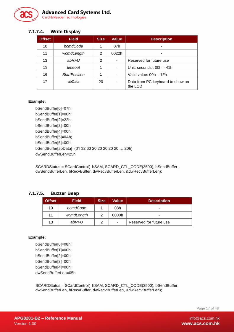
7.1.7.4. Write Display
Offset Field Size Value Description
10 bcmdCode 1 07h -
11 wcmdLength 2 0022h -
13 abRFU 2 - Reserved for future use
15 timeout 1 - Unit: seconds : 00h – 41h
16 StartPosition 1 - Valid value: 00h – 1Fh
17 abData 20 - Data from PC keyboard to show on the LCD
Example:
bSendBuffer[0]=07h;
bSendBuffer[1]=00h;
bSendBuffer[2]=22h;
bSendBuffer[3]=00h
bSendBuffer[4]=00h;
bSendBuffer[5]=0Ah;
bSendBuffer[6]=00h;
bSendBuffer[abData]=(31 32 33 20 20 20 20 20 … 20h)
dwSendBufferLen=25h
SCARDStatus = SCardControl( hSAM, SCARD_CTL_CODE(3500), bSendBuffer, dwSendBufferLen, bRecvBuffer, dwRecvBufferLen, &dwRecvBufferLen);
7.1.7.5. Buzzer Beep
Offset Field Size Value Description
10 bcmdCode 1 08h -
11 wcmdLength 2 0000h -
13 abRFU 2 - Reserved for future use
Example:
bSendBuffer[0]=08h;
bSendBuffer[1]=00h;
bSendBuffer[2]=00h;
bSendBuffer[3]=00h;
bSendBuffer[4]=00h;
dwSendBufferLen=05h
SCARDStatus = SCardControl( hSAM, SCARD_CTL_CODE(3500), bSendBuffer, dwSendBufferLen, bRecvBuffer, dwRecvBufferLen, &dwRecvBufferLen);
APG8201-B2 – Reference Manual [email protected]
Version 1.00 www.acs.com.hk
Page 18 of 48
www.acs.com.hk
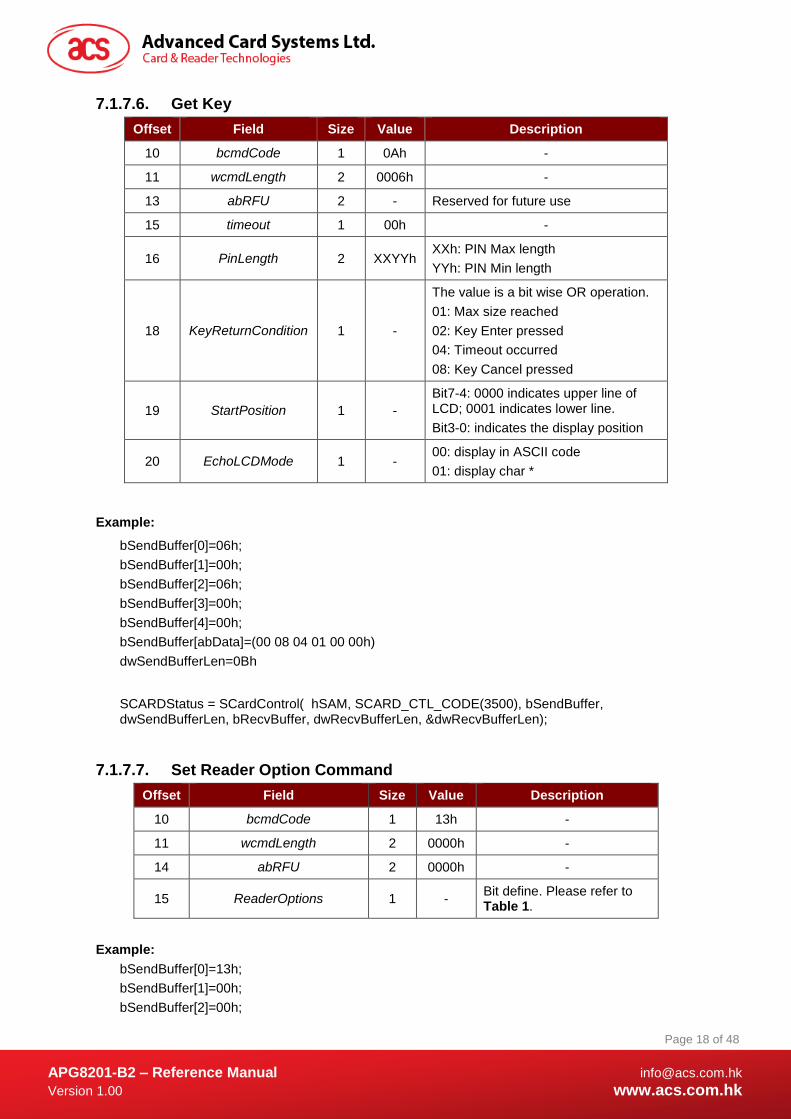
7.1.7.6. Get Key
Offset Field Size Value Description
10 bcmdCode 1 0Ah -
11 wcmdLength 2 0006h -
13 abRFU 2 - Reserved for future use
15 timeout 1 00h -
16 PinLength 2 XXYYh XXh: PIN Max length
YYh: PIN Min length
18 KeyReturnCondition 1 -
The value is a bit wise OR operation.
01: Max size reached
02: Key Enter pressed
04: Timeout occurred
08: Key Cancel pressed
19 StartPosition 1 -
Bit7-4: 0000 indicates upper line of LCD; 0001 indicates lower line.
Bit3-0: indicates the display position
20 EchoLCDMode 1 - 00: display in ASCII code
01: display char *
Example:
bSendBuffer[0]=06h;
bSendBuffer[1]=00h;
bSendBuffer[2]=06h;
bSendBuffer[3]=00h;
bSendBuffer[4]=00h;
bSendBuffer[abData]=(00 08 04 01 00 00h)
dwSendBufferLen=0Bh
SCARDStatus = SCardControl( hSAM, SCARD_CTL_CODE(3500), bSendBuffer, dwSendBufferLen, bRecvBuffer, dwRecvBufferLen, &dwRecvBufferLen);
7.1.7.7. Set Reader Option Command
Offset Field Size Value Description
10 bcmdCode 1 13h -
11 wcmdLength 2 0000h -
14 abRFU 2 0000h -
15 ReaderOptions 1 - Bit define. Please refer to Table 1.
Example:
bSendBuffer[0]=13h;
bSendBuffer[1]=00h;
bSendBuffer[2]=00h;
APG8201-B2 – Reference Manual [email protected]
Version 1.00 www.acs.com.hk
Page 19 of 48
www.acs.com.hk
bSendBuffer[3]=00h;
bSendBuffer[4]=00h;
bSendBuffer[5]=02h;
dwSendBufferLen=06h
SCARDStatus = SCardControl( hSAM, SCARD_CTL_CODE(3500), bSendBuffer, dwSendBufferLen, bRecvBuffer, dwRecvBufferLen, &dwRecvBufferLen);
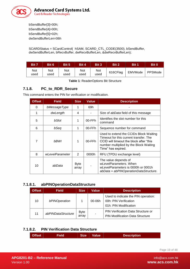
Bit 7 Bit 6 Bit 5 Bit 4 Bit 3 Bit 2 Bit 1 Bit 0
Not used
Not used
Not used
Not used
Not used
616CFlag EMVMode PPSMode
Table 1: ReaderOptions Bit Structure
7.1.8. PC_to_RDR_Secure
This command enters the PIN for verification or modification.
Offset Field Size Value Description
0 bMessageType 1 69h -
1 dwLength 4 - Size of abData field of this message
5 bSlot 1 00-FFh Identifies the slot number for this command
6 bSeq 1 00-FFh Sequence number for command
7 bBWI 1 00-FFh
Used to extend the CCIDs Block Waiting Timeout for this current transfer. The CCID will timeout the block after “this number multiplied by the Block Waiting Time” has expired.
8 wLevelParameter 2 0000h RFU (TPDU exchange level)
10 abData Byte array
-
The value depends of wLevelParameters. When wLevelParameters is 0000h or 0001h abData = abPINOperationDataStructure.
7.1.8.1. abPINOperationDataStructure
Offset Field Size Value Description
10 bPINOperation 1 00-06h
Used to indicate the PIN operation:
00h: PIN Verification
01h: PIN Modification
11 abPINDataStructure Byte array
- PIN Verification Data Structure or
PIN Modification Data Structure
7.1.8.2. PIN Verification Data Structure
Offset Field Size Value Description

APG8201-B2 – Reference Manual [email protected]
Version 1.00 www.acs.com.hk
Page 20 of 48
www.acs.com.hk
Offset Field Size Value Description
11 bTimeOut 1 - Number of seconds. If 00h then CCID default value is used.
12 bmFormatString 1 - Several parameters for the PIN format options
13 bmPINBlockString 1 - Defines the length in bytes of the PIN block to present in the APDU command
14 bmPINLengthFormat 1 - Allows the insertion of the PIN length in the APDU command
15 wPINMaxExtraDigit 2 XXYYh XX: Minimum PIN size in digit
YY: Maximum PIN size in digit
17 bEntryValidationCond
ition 1 -
The value is a bit wise OR operation:
01h: Max size reached
02h: Validation key pressed
04h: Timeout occurred
18 bNumberMessage 1
00h
01h
FFh
Number of messages to display for the PIN Verification management:
00h: no string
01h: Message which index is indicated in bMsgIndex
FFh: default CCID message
19 wLangId 2 - Language used to display the messages
21 bMsgIndex 1 -
Message index in the Reader CCID message table (should be 00h). The message is the prompt for the user to enter their PIN.
22 bTeoPrologue 3 - T=1 I-block prologue field to use. Significant only if protocol in use is T=1.
25 abPINApdu Byte array
- APDU to send to the ICC
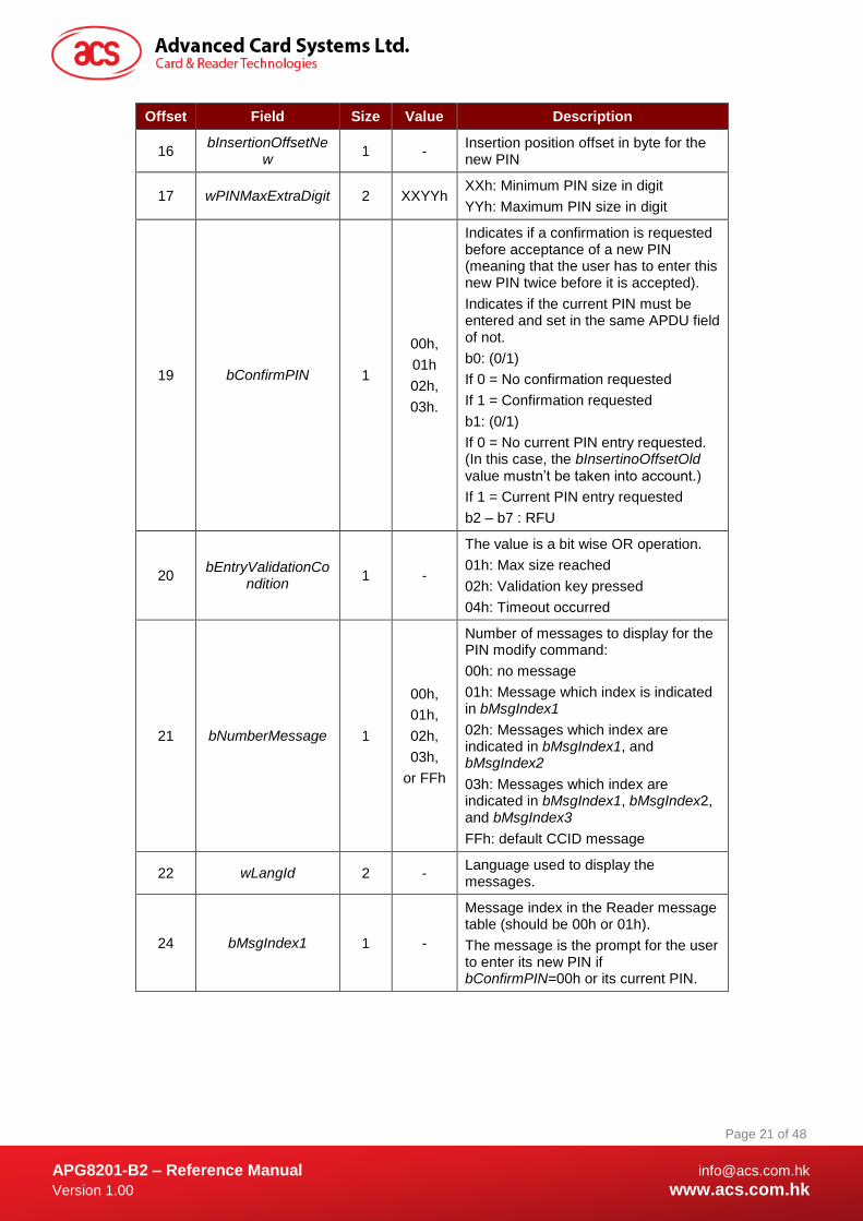
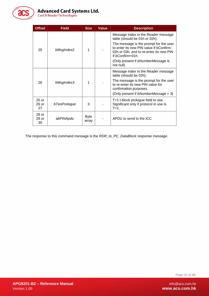
7.1.8.3. PIN Modification Data Structure
Offset Field Size Value Description
11 bTimeOut 1 - Number of seconds. If 00h then CCID default value is used.
12 bmFormatString 1 - Several parameters for the PIN format options
13 bmPINBlockString 1 - Defines the length in bytes of the PIN block to present in the APDU command
14 bmPINLengthForm
at 1 -
Allows the insertion of the PIN length in the APDU command
15 bInsertionOffsetOld 1 - Insertion position offset in byte for the current PIN
APG8201-B2 – Reference Manual [email protected]
Version 1.00 www.acs.com.hk
Page 21 of 48
www.acs.com.hk
Offset Field Size Value Description
16 bInsertionOffsetNe
w 1 -
Insertion position offset in byte for the new PIN
17 wPINMaxExtraDigit 2 XXYYh XXh: Minimum PIN size in digit
YYh: Maximum PIN size in digit
19 bConfirmPIN 1
00h,
01h
02h,
03h.
Indicates if a confirmation is requested before acceptance of a new PIN (meaning that the user has to enter this new PIN twice before it is accepted).
Indicates if the current PIN must be entered and set in the same APDU field of not.
b0: (0/1)
If 0 = No confirmation requested
If 1 = Confirmation requested
b1: (0/1)
If 0 = No current PIN entry requested. (In this case, the bInsertinoOffsetOld value mustn’t be taken into account.)
If 1 = Current PIN entry requested
b2 – b7 : RFU
20 bEntryValidationCo
ndition 1 -
The value is a bit wise OR operation.
01h: Max size reached
02h: Validation key pressed
04h: Timeout occurred
21 bNumberMessage 1
00h,
01h,
02h,
03h,
or FFh
Number of messages to display for the PIN modify command:
00h: no message
01h: Message which index is indicated in bMsgIndex1
02h: Messages which index are indicated in bMsgIndex1, and bMsgIndex2
03h: Messages which index are indicated in bMsgIndex1, bMsgIndex2, and bMsgIndex3
FFh: default CCID message
22 wLangId 2 - Language used to display the messages.
24 bMsgIndex1 1 -
Message index in the Reader message table (should be 00h or 01h).
The message is the prompt for the user to enter its new PIN if bConfirmPIN=00h or its current PIN.
APG8201-B2 – Reference Manual [email protected]
Version 1.00 www.acs.com.hk
Page 22 of 48
www.acs.com.hk
Offset Field Size Value Description
25 bMsgIndex2 1 -
Message index in the Reader message table (should be 01h or 02h).
The message is the prompt for the user to enter its new PIN value if bConfirm-02h or 03h, and to re-enter its new PIN if bConfirm=01h.
(Only present if bNumberMessage is not null)
26 bMsgIndex3 1 -
Message index in the Reader message table (should be 02h).
The message is the prompt for the user to re-enter its new PIN value for confirmation purposes.
(Only present if bNumberMessage = 3)
25 or 26 or
27 bTeoPrologue 3 -
T=1 I-block prologue field to use. Significant only if protocol in use is T=1.
28 or 29 or
30 abPINApdu
Byte array
- APDU to send to the ICC
The response to this command message is the RDR_to_PC_DataBlock response message.
APG8201-B2 – Reference Manual [email protected]
Version 1.00 www.acs.com.hk
Page 23 of 48
www.acs.com.hk
7.2. Reader to PC
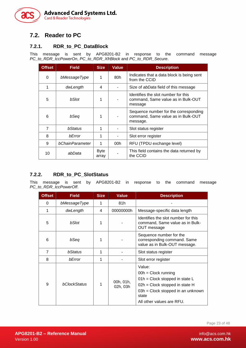
7.2.1. RDR_to_PC_DataBlock
This message is sent by APG8201-B2 in response to the command message PC_to_RDR_IccPowerOn, PC_to_RDR_XfrBlock and PC_to_RDR_Secure.
Offset Field Size Value Description
0 bMessageType 1 80h Indicates that a data block is being sent from the CCID
1 dwLength 4 - Size of abData field of this message
5 bSlot 1 - Identifies the slot number for this command, Same value as in Bulk-OUT message
6 bSeq 1 - Sequence number for the corresponding command, Same value as in Bulk-OUT message.
7 bStatus 1 - Slot status register
8 bError 1 - Slot error register
9 bChainParameter 1 00h RFU (TPDU exchange level)
10 abData Byte array
- This field contains the data returned by the CCID
7.2.2. RDR_to_PC_SlotStatus
This message is sent by APG8201-B2 in response to the command message PC_to_RDR_IccPowerOff.
Offset Field Size Value Description
0 bMessageType 1 81h -
1 dwLength 4 00000000h Message-specific data length
5 bSlot 1 - Identifies the slot number for this command, Same value as in Bulk-OUT message
6 bSeq 1 - Sequence number for the corresponding command. Same value as in Bulk-OUT message.
7 bStatus 1 - Slot status register
8 bError 1 - Slot error register
9 bClockStatus 1 00h, 01h, 02h, 03h
Value:
00h = Clock running
01h = Clock stopped in state L
02h = Clock stopped in state H
03h = Clock stopped in an unknown state
All other values are RFU.

APG8201-B2 – Reference Manual [email protected]
Version 1.00 www.acs.com.hk
Page 24 of 48
www.acs.com.hk
7.2.3. RDR_to_PC_Parameters
This message is sent by APG8201-B2 in response to the command message:
PC_to_RDR_GetParameters, PC_to_RDR_ResetParameters and PC_to_RDR_SetParameters
Offset Field Size Value Description
0 bMessageType 1 82h -
1 dwLength 4 - Size of abProtocolDataStructure field of this message
5 bSlot 1 - Identifies the slot number for this command. Same value as in Bulk-OUT message.
6 bSeq 1 - Sequence number for the corresponding command. Same value as in Bulk-OUT message.
7 bStatus 1 - Slot status register
8 bError 1 - Slot error register
9 bProtocolNum 1 00h,
01h
Specifies what protocol data structure follows:
00h = Structure for protocol T=0
01h = Structure for protocol T=1
The following values are RFU.
80h = Structure for 2-wire protocol
81h = Structure for 3-wire protocol
82h = Structure for I2C protocol
10 abProtocolDataSt
ructure Byte array
- Protocol Data Structure
Protocol Data Structure for Protocol T=0 (bProtocolNum=0, dwLength=00000005h)
Offset Field Size Value Description
10 bmFindexDindex 1 -
B7-4 – FI – Index into the table 7 in ISO/IEC 7816-3:1997 selecting a clock rate conversion factor
B3-0 – DI – Index into the table 8 in ISO/IEC 7816-3:1997 selecting a baud rate conversion factor
11 bmTCCKST0 1 00h,02h
For T=0 ,B0 – 0b, B7-2 – 000000b
B1 – Convention used (b1=0 for direct, b1=1 for inverse)
12 bGuardTimeT0 1 00-FFh
Extra guardtime between two characters. Add 0 to 254 etu to the normal guardtime of 12etu.
FFh is the same as 00h.
13 bWaitingIntegerT0 1 00-FFh WI for T=0 used to define WWT

APG8201-B2 – Reference Manual [email protected]
Version 1.00 www.acs.com.hk
Page 25 of 48
www.acs.com.hk
Offset Field Size Value Description
14 bClockStop 1 00-03h
ICC Clock Stop Support:
00h = Stopping the Clock is not allowed
01h = Stop with Clock signal Low
02h = Stop with Clock signal High
03h = Stop with Clock either High or Low
Protocol Data Structure for Protocol T=1 (bProtocolNum=1, dwLength=00000007h)
Offset Field Size Value Description
10 bmFindexDindex 1 -
B7-4 – FI – Index into the table 7 in ISO/IEC 7816-3:1997 selecting a clock rate conversion factor
B3-0 – DI - Index into the table 8 in ISO/IEC 7816-3:1997 selecting a baud rate conversion factor
11 bmTCCKST1 1
10h,
11h,
12h,
13h
For T=1, B7-2 – 000100b
B0 – Checksum type (b0=0 for LRC, b0=1 for CRC)
B1 – Convention used (b1=0 for direct, b1=1 for inverse)
12 bGuardTimeT1 1 00-FFh Extra guardtime (0 to 254 etu between two characters). If value is FFh, then guardtime is reduced by 1.
13 bWaitingIntegerT1 1 00-9Fh B7-4 = BWI
B3-0 = CWI
14 bClockStop 1 00-03h
ICC Clock Stop Support:
00 = Stopping the Clock is not allowed
01 = Stop with Clock signal Low
02 = Stop with Clock signal High
03 = Stop with Clock either High or Low
15 bIFSC 1 00-FEh Size of negotiated IFSC
16 bNadValue 1 00-FFh Nad value used by CCID
7.2.4. RDR_to_PC_Escape
This message is sent by APG8201-B2 in response to the command message PC_to_RDR_Escape.
Offset Field Size Value Description
0 bMessageType 1 83h -
1 dwLength 4 - Size of abData field of this message
5 bSlot 1 - Identifies the slot number for this command. Same value as in Bulk-OUT message.
6 bSeq 1 - Sequence number for the corresponding command. Same value as in Bulk-OUT message.

APG8201-B2 – Reference Manual [email protected]
Version 1.00 www.acs.com.hk
Page 26 of 48
www.acs.com.hk
Offset Field Size Value Description
7 bStatus 1 - Slot status register
8 bError 1 - Slot error register
9 abRFU 1 00h Reserved for Future Use
10 abData Byte array
- Data sent from CCID
7.2.4.1. Get Reader Specific Tag
Offset Field Size Value Description
10 bRespType 1 80h -
11 wcmdLength 1 04h -
12 abData 4 0x00h -
7.2.4.2. Get Firmware Version
Offset Field Size Value Description
10 bRespType 1 84h -
11 wcmdLength 2 0004h -
13 abRFU 2 0000h Reserved for Future Use
15 abData 4 - Firmware version value
7.2.4.3. Display LCD Message
Offset Field Size Value Description
10 bRespType 1 85h -
11 wcmdLength 2 00h -
12 abRFU 2 00h Reserved for Future Use
7.2.4.4. Read Key
Offset Field Size Value Description
10 bRespType 1 86h -
11 wResLength 2 - -
13 abRFU 2 0000h -
15 abData Byte array
- Data receive from Reader
APG8201-B2 – Reference Manual [email protected]
Version 1.00 www.acs.com.hk
Page 27 of 48
www.acs.com.hk
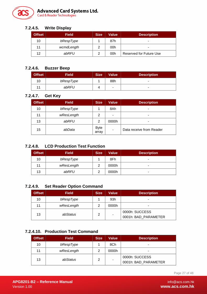
7.2.4.5. Write Display
Offset Field Size Value Description
10 bRespType 1 87h -
11 wcmdLength 2 00h -
12 abRFU 2 00h Reserved for Future Use
7.2.4.6. Buzzer Beep
Offset Field Size Value Description
10 bRespType 1 88h -
11 abRFU 4 - -
7.2.4.7. Get Key
Offset Field Size Value Description
10 bRespType 1 8Ah -
11 wResLength 2 - -
13 abRFU 2 0000h -
15 abData Byte array
- Data receive from Reader
7.2.4.8. LCD Production Test Function
Offset Field Size Value Description
10 bRespType 1 8Fh -
11 wResLength 2 0000h -
13 abRFU 2 0000h -
7.2.4.9. Set Reader Option Command
Offset Field Size Value Description
10 bRespType 1 93h -
11 wResLength 2 0000h -
13 abStatus 2 - 0000h: SUCCESS
0001h: BAD_PARAMETER
7.2.4.10. Production Test Command
Offset Field Size Value Description
10 bRespType 1 8Ch -
11 wResLength 2 0000h -
13 abStatus 2 - 0000h: SUCCESS
0001h: BAD_PARAMETER
APG8201-B2 – Reference Manual [email protected]
Version 1.00 www.acs.com.hk
Page 28 of 48
www.acs.com.hk
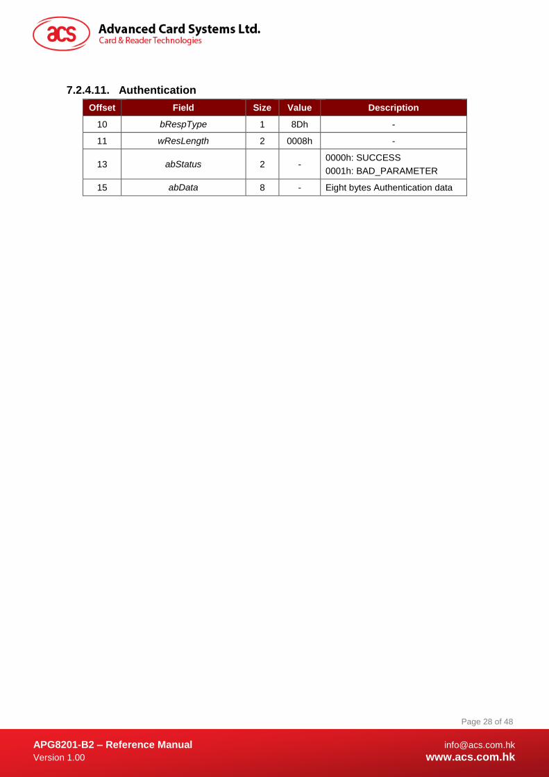
7.2.4.11. Authentication
Offset Field Size Value Description
10 bRespType 1 8Dh -
11 wResLength 2 0008h -
13 abStatus 2 - 0000h: SUCCESS
0001h: BAD_PARAMETER
15 abData 8 - Eight bytes Authentication data
APG8201-B2 – Reference Manual [email protected]
Version 1.00 www.acs.com.hk
Page 29 of 48
www.acs.com.hk
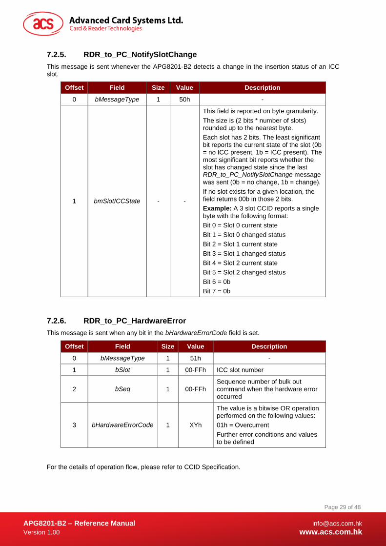
7.2.5. RDR_to_PC_NotifySlotChange
This message is sent whenever the APG8201-B2 detects a change in the insertion status of an ICC slot.
Offset Field Size Value Description
0 bMessageType 1 50h -
1 bmSlotICCState - -
This field is reported on byte granularity.
The size is (2 bits * number of slots) rounded up to the nearest byte.
Each slot has 2 bits. The least significant bit reports the current state of the slot (0b = no ICC present, 1b = ICC present). The most significant bit reports whether the slot has changed state since the last RDR_to_PC_NotifySlotChange message was sent (0b = no change, 1b = change).
If no slot exists for a given location, the field returns 00b in those 2 bits.
Example: A 3 slot CCID reports a single byte with the following format:
Bit 0 = Slot 0 current state
Bit 1 = Slot 0 changed status
Bit 2 = Slot 1 current state
Bit 3 = Slot 1 changed status
Bit 4 = Slot 2 current state
Bit 5 = Slot 2 changed status
Bit 6 = 0b
Bit 7 = 0b
7.2.6. RDR_to_PC_HardwareError
This message is sent when any bit in the bHardwareErrorCode field is set.
Offset Field Size Value Description
0 bMessageType 1 51h -
1 bSlot 1 00-FFh ICC slot number
2 bSeq 1 00-FFh Sequence number of bulk out command when the hardware error occurred
3 bHardwareErrorCode 1 XYh
The value is a bitwise OR operation performed on the following values:
01h = Overcurrent
Further error conditions and values to be defined
For the details of operation flow, please refer to CCID Specification.
APG8201-B2 – Reference Manual [email protected]
Version 1.00 www.acs.com.hk
Page 30 of 48
www.acs.com.hk
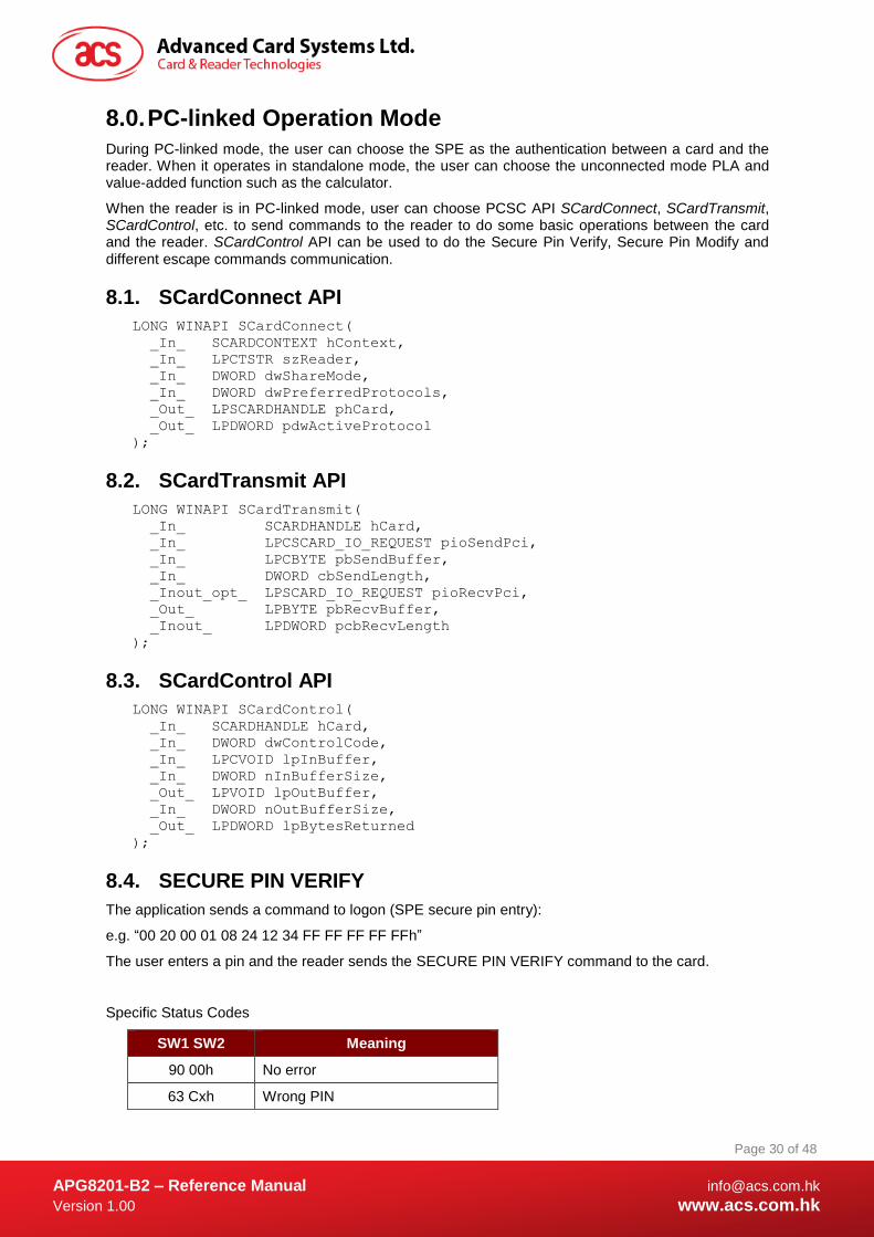
8.0. PC-linked Operation Mode
During PC-linked mode, the user can choose the SPE as the authentication between a card and the reader. When it operates in standalone mode, the user can choose the unconnected mode PLA and value-added function such as the calculator.
When the reader is in PC-linked mode, user can choose PCSC API SCardConnect, SCardTransmit, SCardControl, etc. to send commands to the reader to do some basic operations between the card and the reader. SCardControl API can be used to do the Secure Pin Verify, Secure Pin Modify and different escape commands communication.
8.1. SCardConnect API
LONG WINAPI SCardConnect(
_In_ SCARDCONTEXT hContext,
_In_ LPCTSTR szReader,
_In_ DWORD dwShareMode,
_In_ DWORD dwPreferredProtocols,
_Out_ LPSCARDHANDLE phCard,
_Out_ LPDWORD pdwActiveProtocol
);
8.2. SCardTransmit API
LONG WINAPI SCardTransmit(
_In_ SCARDHANDLE hCard,
_In_ LPCSCARD_IO_REQUEST pioSendPci,
_In_ LPCBYTE pbSendBuffer,
_In_ DWORD cbSendLength,
_Inout_opt_ LPSCARD_IO_REQUEST pioRecvPci,
_Out_ LPBYTE pbRecvBuffer,
_Inout_ LPDWORD pcbRecvLength
);
8.3. SCardControl API
LONG WINAPI SCardControl(
_In_ SCARDHANDLE hCard,
_In_ DWORD dwControlCode,
_In_ LPCVOID lpInBuffer,
_In_ DWORD nInBufferSize,
_Out_ LPVOID lpOutBuffer,
_In_ DWORD nOutBufferSize,
_Out_ LPDWORD lpBytesReturned
);
8.4. SECURE PIN VERIFY
The application sends a command to logon (SPE secure pin entry):
e.g. “00 20 00 01 08 24 12 34 FF FF FF FF FFh”
The user enters a pin and the reader sends the SECURE PIN VERIFY command to the card.
Specific Status Codes
SW1 SW2 Meaning
90 00h No error
63 Cxh Wrong PIN
APG8201-B2 – Reference Manual [email protected]
Version 1.00 www.acs.com.hk
Page 31 of 48
www.acs.com.hk
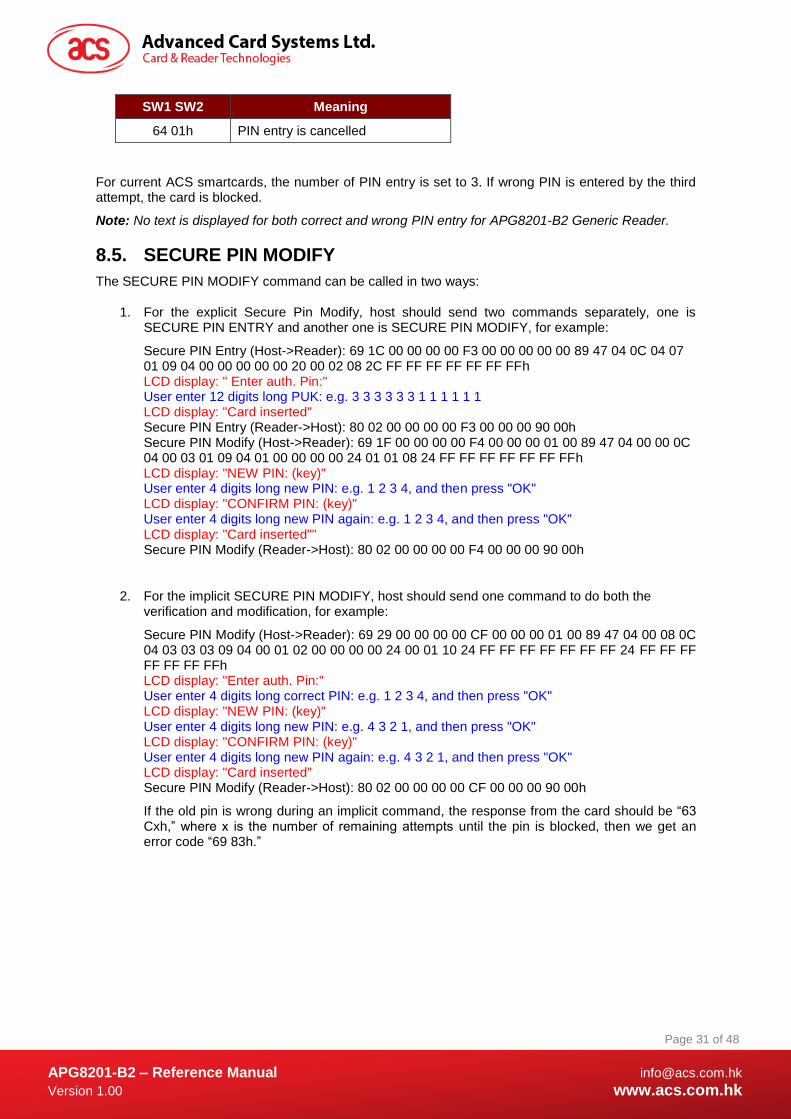
SW1 SW2 Meaning
64 01h PIN entry is cancelled
For current ACS smartcards, the number of PIN entry is set to 3. If wrong PIN is entered by the third attempt, the card is blocked.
Note: No text is displayed for both correct and wrong PIN entry for APG8201-B2 Generic Reader.
8.5. SECURE PIN MODIFY
The SECURE PIN MODIFY command can be called in two ways:
1. For the explicit Secure Pin Modify, host should send two commands separately, one is SECURE PIN ENTRY and another one is SECURE PIN MODIFY, for example:
Secure PIN Entry (Host->Reader): 69 1C 00 00 00 00 F3 00 00 00 00 00 89 47 04 0C 04 07 01 09 04 00 00 00 00 00 20 00 02 08 2C FF FF FF FF FF FF FFh LCD display: " Enter auth. Pin:" User enter 12 digits long PUK: e.g. 3 3 3 3 3 3 1 1 1 1 1 1 LCD display: "Card inserted" Secure PIN Entry (Reader->Host): 80 02 00 00 00 00 F3 00 00 00 90 00h Secure PIN Modify (Host->Reader): 69 1F 00 00 00 00 F4 00 00 00 01 00 89 47 04 00 00 0C 04 00 03 01 09 04 01 00 00 00 00 24 01 01 08 24 FF FF FF FF FF FF FFh LCD display: "NEW PIN: (key)" User enter 4 digits long new PIN: e.g. 1 2 3 4, and then press "OK" LCD display: "CONFIRM PIN: (key)" User enter 4 digits long new PIN again: e.g. 1 2 3 4, and then press "OK" LCD display: "Card inserted"" Secure PIN Modify (Reader->Host): 80 02 00 00 00 00 F4 00 00 00 90 00h
2. For the implicit SECURE PIN MODIFY, host should send one command to do both the verification and modification, for example:
Secure PIN Modify (Host->Reader): 69 29 00 00 00 00 CF 00 00 00 01 00 89 47 04 00 08 0C 04 03 03 03 09 04 00 01 02 00 00 00 00 24 00 01 10 24 FF FF FF FF FF FF FF 24 FF FF FF FF FF FF FFh LCD display: "Enter auth. Pin:" User enter 4 digits long correct PIN: e.g. 1 2 3 4, and then press "OK" LCD display: "NEW PIN: (key)" User enter 4 digits long new PIN: e.g. 4 3 2 1, and then press "OK" LCD display: "CONFIRM PIN: (key)" User enter 4 digits long new PIN again: e.g. 4 3 2 1, and then press "OK" LCD display: "Card inserted" Secure PIN Modify (Reader->Host): 80 02 00 00 00 00 CF 00 00 00 90 00h
If the old pin is wrong during an implicit command, the response from the card should be “63 Cxh,” where x is the number of remaining attempts until the pin is blocked, then we get an error code “69 83h.”
APG8201-B2 – Reference Manual [email protected]
Version 1.00 www.acs.com.hk
Page 32 of 48
www.acs.com.hk
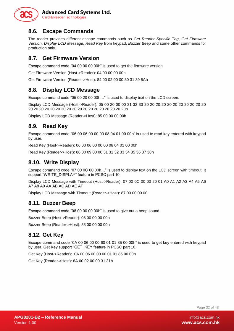
8.6. Escape Commands
The reader provides different escape commands such as Get Reader Specific Tag, Get Firmware Version, Display LCD Message, Read Key from keypad, Buzzer Beep and some other commands for production only.
8.7. Get Firmware Version
Escape command code “04 00 00 00 00h” is used to get the firmware version.
Get Firmware Version (Host->Reader): 04 00 00 00 00h
Get Firmware Version (Reader->Host): 84 00 02 00 00 30 31 39 5Ah
8.8. Display LCD Message
Escape command code “05 00 20 00 00h…” is used to display text on the LCD screen.
Display LCD Message (Host->Reader): 05 00 20 00 00 31 32 33 20 20 20 20 20 20 20 20 20 20 20 20 20 20 20 20 20 20 20 20 20 20 20 20 20 20 20 20 20h
Display LCD Message (Reader->Host): 85 00 00 00 00h
8.9. Read Key
Escape command code “06 00 06 00 00 00 08 04 01 00 00h” is used to read key entered with keypad by user.
Read Key (Host->Reader): 06 00 06 00 00 00 08 04 01 00 00h
Read Key (Reader->Host): 86 00 09 00 00 31 31 32 33 34 35 36 37 38h
8.10. Write Display
Escape command code “07 00 0C 00 00h…” is used to display text on the LCD screen with timeout. It support “WRITE_DISPLAY” feature in PCSC part 10
Display LCD Message with Timeout (Host->Reader): 07 00 0C 00 00 20 01 A0 A1 A2 A3 A4 A5 A6 A7 A8 A9 AA AB AC AD AE AF
Display LCD Message with Timeout (Reader->Host): 87 00 00 00 00
8.11. Buzzer Beep
Escape command code “08 00 00 00 00h” is used to give out a beep sound.
Buzzer Beep (Host->Reader): 08 00 00 00 00h
Buzzer Beep (Reader->Host): 88 00 00 00 00h
8.12. Get Key
Escape command code “0A 00 06 00 00 60 01 01 85 00 00h” is used to get key entered with keypad by user. Get Key support “GET_KEY feature in PCSC part 10.
Get Key (Host->Reader): 0A 00 06 00 00 60 01 01 85 00 00h
Get Key (Reader->Host): 8A 00 02 00 00 31 31h
APG8201-B2 – Reference Manual [email protected]
Version 1.00 www.acs.com.hk
Page 33 of 48
www.acs.com.hk
9.0. Device Control
This section describes the system smart card device IOCTLs.
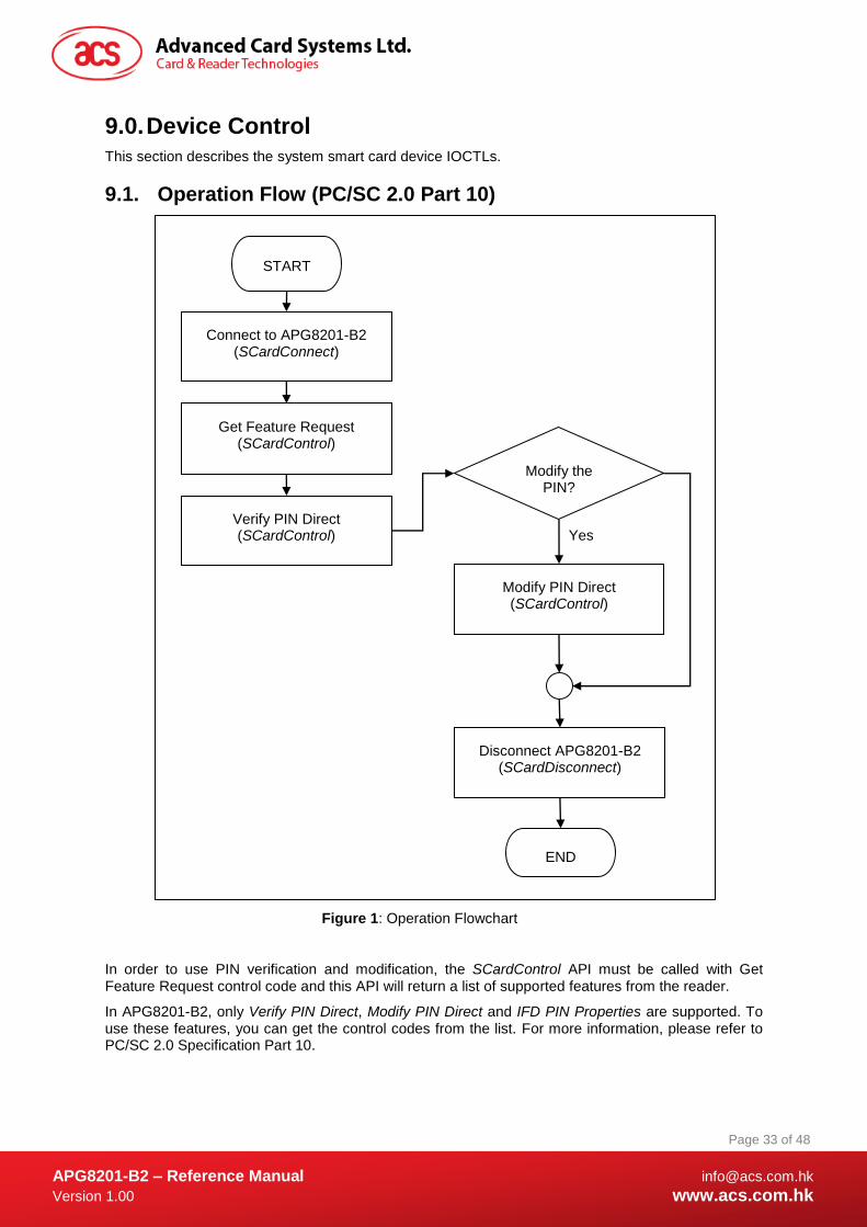
9.1. Operation Flow (PC/SC 2.0 Part 10)
Figure 1: Operation Flowchart
In order to use PIN verification and modification, the SCardControl API must be called with Get Feature Request control code and this API will return a list of supported features from the reader.
In APG8201-B2, only Verify PIN Direct, Modify PIN Direct and IFD PIN Properties are supported. To use these features, you can get the control codes from the list. For more information, please refer to PC/SC 2.0 Specification Part 10.
START
END
Connect to APG8201-B2 (SCardConnect)
Get Feature Request (SCardControl)
Verify PIN Direct (SCardControl)
Disconnect APG8201-B2 (SCardDisconnect)
Modify PIN Direct (SCardControl)
Modify the PIN?
Yes
APG8201-B2 – Reference Manual [email protected]
Version 1.00 www.acs.com.hk
Page 34 of 48
www.acs.com.hk
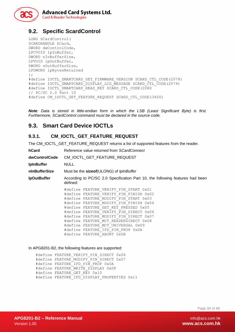
9.2. Specific ScardControl
LONG SCardControl(
SCARDHANDLE hCard,
DWORD dwControlCode,
LPCVOID lpInBuffer,
DWORD nInBufferSize,
LPVOID lpOutBuffer,
DWORD nOutBufferSize,
LPDWORD lpBytesReturned
);
#define IOCTL_SMARTCARD_GET_FIRMWARE_VERSION SCARD_CTL_CODE(2078)
#define IOCTL_SMARTCARD_DISPLAY_LCD_MESSAGE SCARD_CTL_CODE(2079)
#define IOCTL_SMARTCARD_READ_KEY SCARD_CTL_CODE(2080
// PC/SC 2.0 Part 10
#define CM_IOCTL_GET_FEATURE_REQUEST SCARD_CTL_CODE(3400)
Note: Data is stored in little-endian form in which the LSB (Least Significant Byte) is first. Furthermore, SCardControl command must be declared in the source code.
9.3. Smart Card Device IOCTLs
9.3.1. CM_IOCTL_GET_FEATURE_REQUEST
The CM_IOCTL_GET_FEATURE_REQUEST returns a list of supported features from the reader.
hCard Reference value returned from SCardConnect
dwControlCode CM_IOCTL_GET_FEATURE_REQUEST
lpInBuffer NULL
nInBufferSize Must be the sizeof(ULONG) of IpInBuffer
lpOutBuffer According to PC/SC 2.0 Specification Part 10, the following features had been defined:
#define FEATURE_VERIFY_PIN_START 0x01
#define FEATURE_VERIFY_PIN_FINISH 0x02
#define FEATURE_MODIFY_PIN_START 0x03
#define FEATURE_MODIFY_PIN_FINISH 0x04
#define FEATURE_GET_KEY_PRESSED 0x05
#define FEATURE_VERIFY_PIN_DIRECT 0x06
#define FEATURE_MODIFY_PIN_DIRECT 0x07
#define FEATURE_MCT_READERDIRECT 0x08
#define FEATURE_MCT_UNIVERSAL 0x09
#define FEATURE_IFD_PIN_PROP 0x0A
#define FEATURE_ABORT 0x0B
In APG8201-B2, the following features are supported:
#define FEATURE_VERIFY_PIN_DIRECT 0x06
#define FEATURE_MODIFY_PIN_DIRECT 0x07
#define FEATURE_IFD_PIN_PROP 0x0A
#define FEATURE_WRITE_DISPLAY 0x0F
#define FEATURE_GET_KEY 0x10
#define FEATURE_IFD_DISPLAY_PROPERTIES 0x11
APG8201-B2 – Reference Manual [email protected]
Version 1.00 www.acs.com.hk
Page 35 of 48
www.acs.com.hk
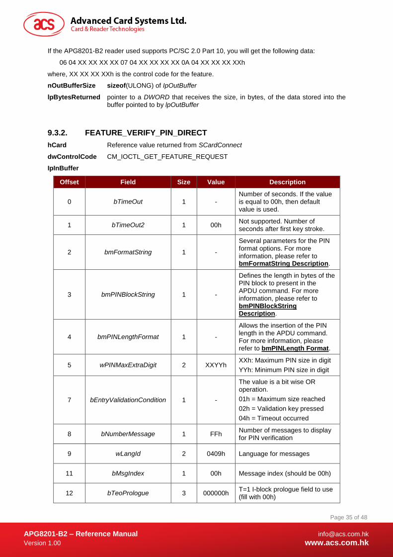
If the APG8201-B2 reader used supports PC/SC 2.0 Part 10, you will get the following data:
06 04 XX XX XX XX 07 04 XX XX XX XX 0A 04 XX XX XX XXh
where, XX XX XX XXh is the control code for the feature.
nOutBufferSize sizeof(ULONG) of IpOutBuffer
lpBytesReturned pointer to a DWORD that receives the size, in bytes, of the data stored into the buffer pointed to by lpOutBuffer
9.3.2. FEATURE_VERIFY_PIN_DIRECT
hCard Reference value returned from SCardConnect
dwControlCode CM_IOCTL_GET_FEATURE_REQUEST
IpInBuffer
Offset Field Size Value Description
0 bTimeOut 1 - Number of seconds. If the value is equal to 00h, then default value is used.
1 bTimeOut2 1 00h Not supported. Number of seconds after first key stroke.
2 bmFormatString 1 -
Several parameters for the PIN format options. For more information, please refer to bmFormatString Description.
3 bmPINBlockString 1 -
Defines the length in bytes of the PIN block to present in the APDU command. For more information, please refer to bmPINBlockString Description.
4 bmPINLengthFormat 1 -
Allows the insertion of the PIN length in the APDU command. For more information, please refer to bmPINLength Format.
5 wPINMaxExtraDigit 2 XXYYh XXh: Maximum PIN size in digit
YYh: Minimum PIN size in digit
7 bEntryValidationCondition 1 -
The value is a bit wise OR operation.
01h = Maximum size reached
02h = Validation key pressed
04h = Timeout occurred
8 bNumberMessage 1 FFh Number of messages to display for PIN verification
9 wLangId 2 0409h Language for messages
11 bMsgIndex 1 00h Message index (should be 00h)
12 bTeoPrologue 3 000000h T=1 I-block prologue field to use (fill with 00h)
APG8201-B2 – Reference Manual [email protected]
Version 1.00 www.acs.com.hk
Page 36 of 48
www.acs.com.hk
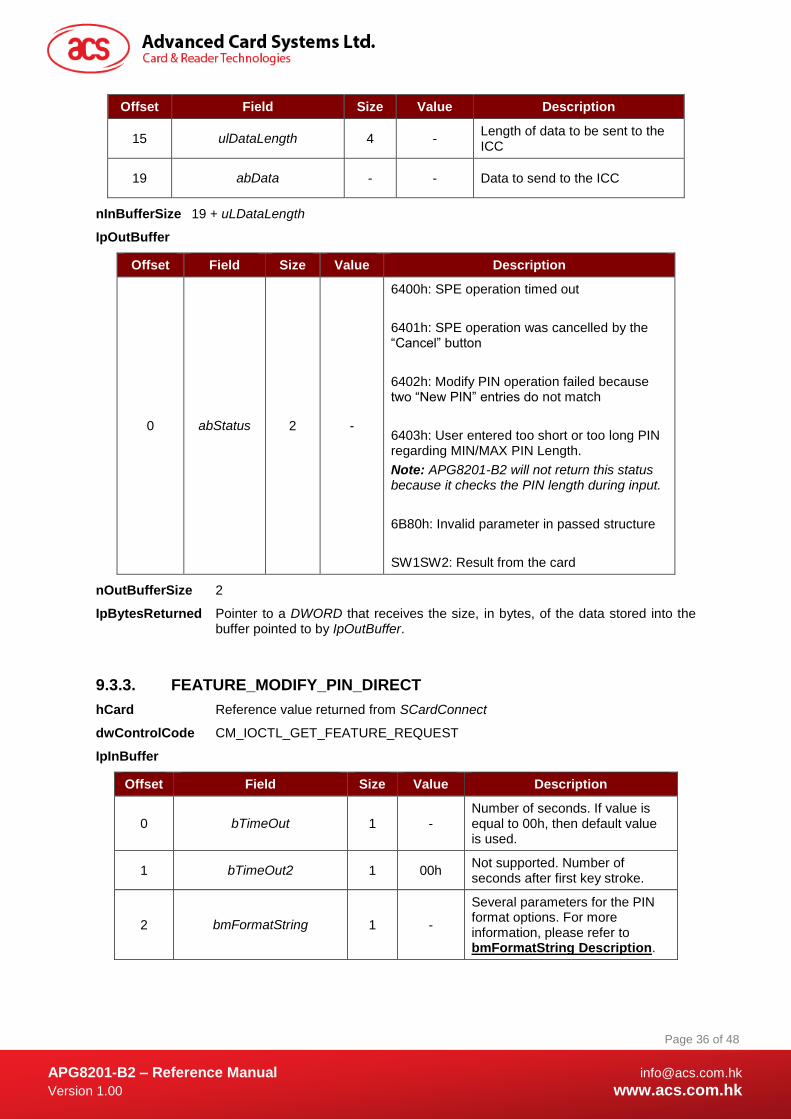
Offset Field Size Value Description
15 ulDataLength 4 - Length of data to be sent to the ICC
19 abData - - Data to send to the ICC
nInBufferSize 19 + uLDataLength
IpOutBuffer
Offset Field Size Value Description
0 abStatus 2 -
6400h: SPE operation timed out
6401h: SPE operation was cancelled by the “Cancel” button
6402h: Modify PIN operation failed because two “New PIN” entries do not match
6403h: User entered too short or too long PIN regarding MIN/MAX PIN Length.
Note: APG8201-B2 will not return this status because it checks the PIN length during input.
6B80h: Invalid parameter in passed structure
SW1SW2: Result from the card
nOutBufferSize 2
IpBytesReturned Pointer to a DWORD that receives the size, in bytes, of the data stored into the buffer pointed to by IpOutBuffer.
9.3.3. FEATURE_MODIFY_PIN_DIRECT
hCard Reference value returned from SCardConnect
dwControlCode CM_IOCTL_GET_FEATURE_REQUEST
IpInBuffer
Offset Field Size Value Description
0 bTimeOut 1 - Number of seconds. If value is equal to 00h, then default value is used.
1 bTimeOut2 1 00h Not supported. Number of seconds after first key stroke.
2 bmFormatString 1 -
Several parameters for the PIN format options. For more information, please refer to bmFormatString Description.
APG8201-B2 – Reference Manual [email protected]
Version 1.00 www.acs.com.hk
Page 37 of 48
www.acs.com.hk
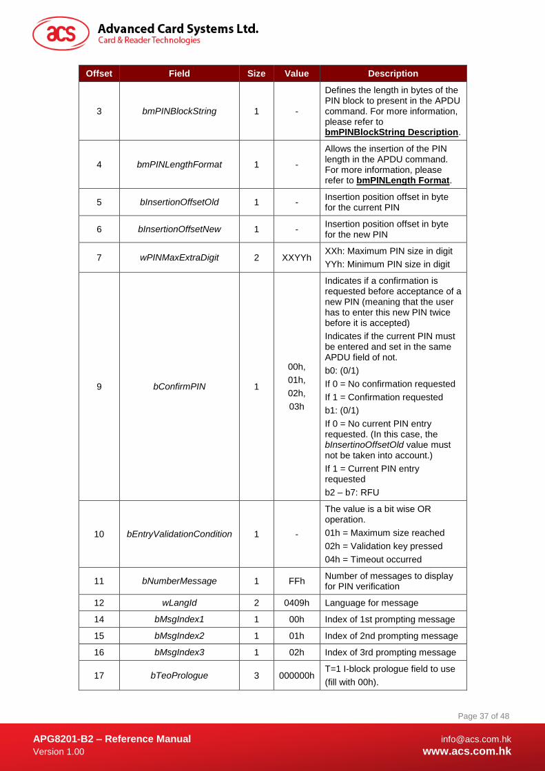
Offset Field Size Value Description
3 bmPINBlockString 1 -
Defines the length in bytes of the PIN block to present in the APDU command. For more information, please refer to bmPINBlockString Description.
4 bmPINLengthFormat 1 -
Allows the insertion of the PIN length in the APDU command. For more information, please refer to bmPINLength Format.
5 bInsertionOffsetOld 1 - Insertion position offset in byte for the current PIN
6 bInsertionOffsetNew 1 - Insertion position offset in byte for the new PIN
7 wPINMaxExtraDigit 2 XXYYh XXh: Maximum PIN size in digit
YYh: Minimum PIN size in digit
9 bConfirmPIN 1
00h,
01h,
02h,
03h
Indicates if a confirmation is requested before acceptance of a new PIN (meaning that the user has to enter this new PIN twice before it is accepted)
Indicates if the current PIN must be entered and set in the same APDU field of not.
b0: (0/1)
If 0 = No confirmation requested
If 1 = Confirmation requested
b1: (0/1)
If 0 = No current PIN entry requested. (In this case, the bInsertinoOffsetOld value must not be taken into account.)
If 1 = Current PIN entry requested
b2 – b7: RFU
10 bEntryValidationCondition 1 -
The value is a bit wise OR operation.
01h = Maximum size reached
02h = Validation key pressed
04h = Timeout occurred
11 bNumberMessage 1 FFh Number of messages to display for PIN verification
12 wLangId 2 0409h Language for message
14 bMsgIndex1 1 00h Index of 1st prompting message
15 bMsgIndex2 1 01h Index of 2nd prompting message
16 bMsgIndex3 1 02h Index of 3rd prompting message
17 bTeoPrologue 3 000000h T=1 I-block prologue field to use
(fill with 00h).
APG8201-B2 – Reference Manual [email protected]
Version 1.00 www.acs.com.hk
Page 38 of 48
www.acs.com.hk
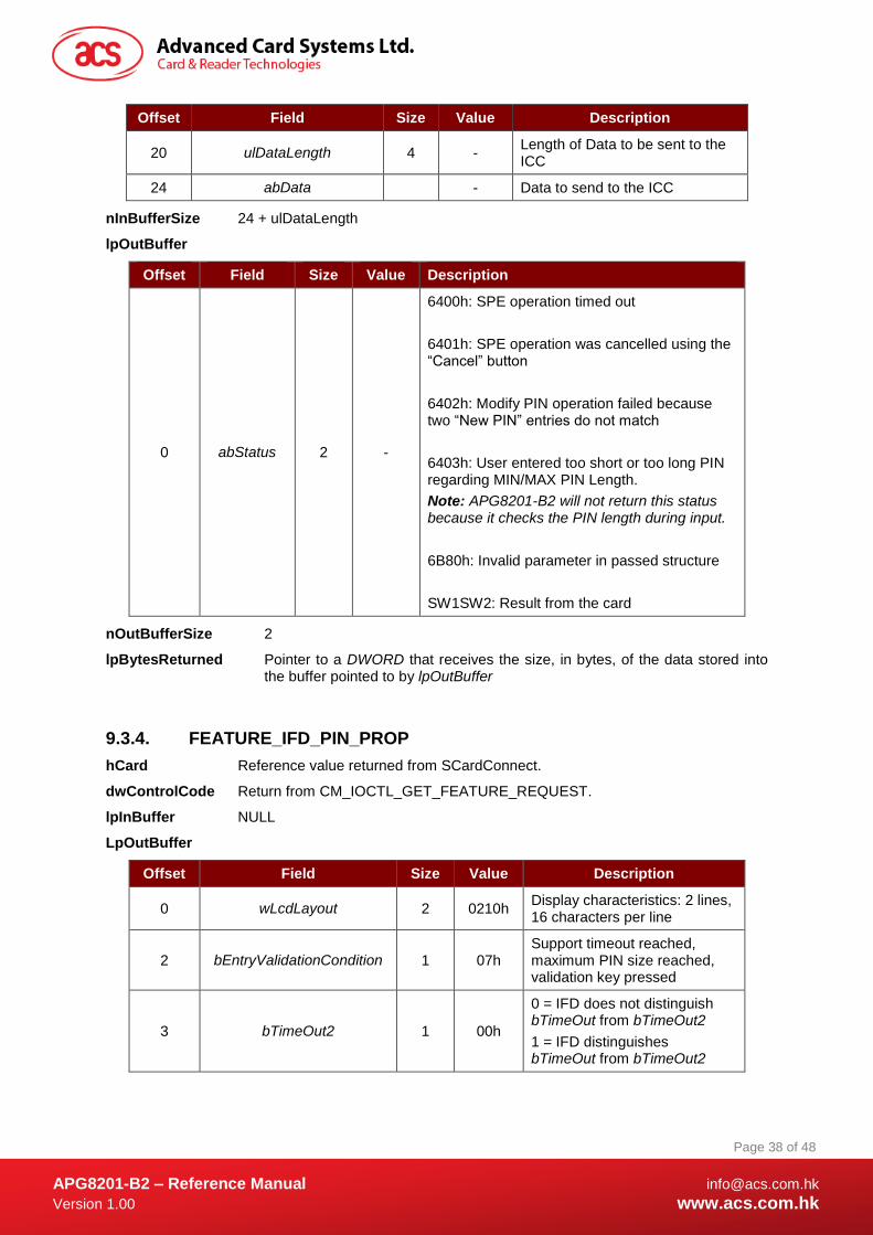
Offset Field Size Value Description
20 ulDataLength 4 - Length of Data to be sent to the ICC
24 abData - Data to send to the ICC
nInBufferSize 24 + ulDataLength
lpOutBuffer
Offset Field Size Value Description
0 abStatus 2 -
6400h: SPE operation timed out
6401h: SPE operation was cancelled using the “Cancel” button
6402h: Modify PIN operation failed because two “New PIN” entries do not match
6403h: User entered too short or too long PIN regarding MIN/MAX PIN Length.
Note: APG8201-B2 will not return this status because it checks the PIN length during input.
6B80h: Invalid parameter in passed structure
SW1SW2: Result from the card
nOutBufferSize 2
lpBytesReturned Pointer to a DWORD that receives the size, in bytes, of the data stored into the buffer pointed to by lpOutBuffer
9.3.4. FEATURE_IFD_PIN_PROP
hCard Reference value returned from SCardConnect.
dwControlCode Return from CM_IOCTL_GET_FEATURE_REQUEST.
lpInBuffer NULL
LpOutBuffer
Offset Field Size Value Description
0 wLcdLayout 2 0210h Display characteristics: 2 lines, 16 characters per line
2 bEntryValidationCondition 1 07h Support timeout reached, maximum PIN size reached, validation key pressed
3 bTimeOut2 1 00h
0 = IFD does not distinguish bTimeOut from bTimeOut2
1 = IFD distinguishes bTimeOut from bTimeOut2
APG8201-B2 – Reference Manual [email protected]
Version 1.00 www.acs.com.hk
Page 39 of 48
www.acs.com.hk
nOutBufferSize 4
lpBytesReturned Pointer to a DWORD that receives the size, in bytes, of the data stored into the buffer pointed to by lpOutBuffer
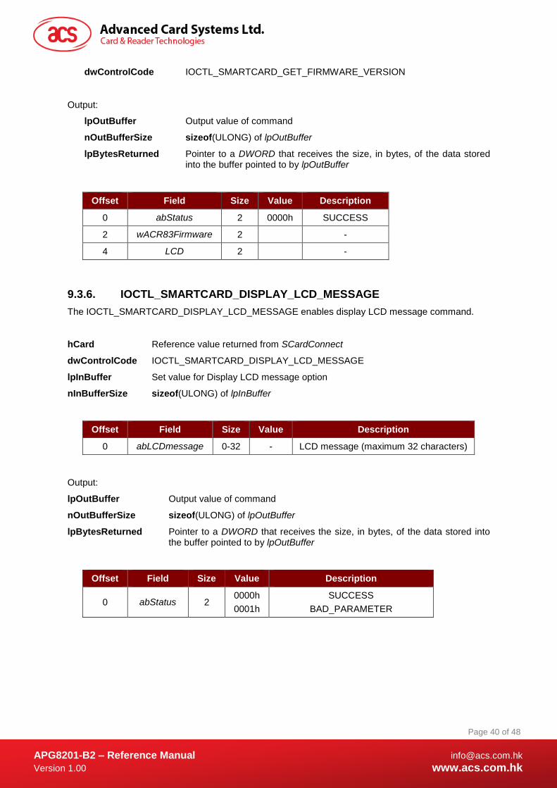
9.3.5. IOCTL_SMARTCARD_GET_FIRMWARE_VERSION
The IOCTL_SMARTCARD_GET_FIRMWARE_VERSION enables Get Firmware Version command.
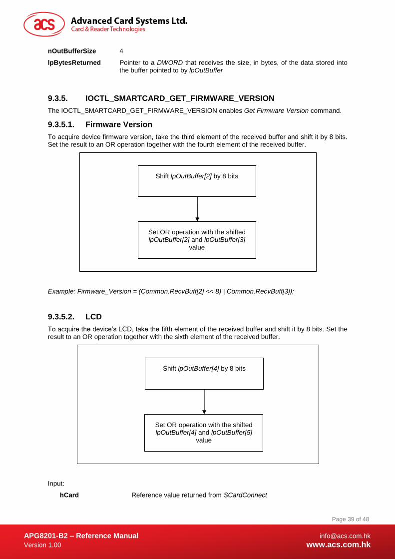
9.3.5.1. Firmware Version
To acquire device firmware version, take the third element of the received buffer and shift it by 8 bits. Set the result to an OR operation together with the fourth element of the received buffer.
Example: Firmware_Version = (Common.RecvBuff[2] << 8) | Common.RecvBuff[3]);
9.3.5.2. LCD
To acquire the device’s LCD, take the fifth element of the received buffer and shift it by 8 bits. Set the result to an OR operation together with the sixth element of the received buffer.
Input:
hCard Reference value returned from SCardConnect
Shift lpOutBuffer[2] by 8 bits
Set OR operation with the shifted lpOutBuffer[2] and lpOutBuffer[3]
value
Shift lpOutBuffer[4] by 8 bits
Set OR operation with the shifted lpOutBuffer[4] and lpOutBuffer[5]
value
APG8201-B2 – Reference Manual [email protected]
Version 1.00 www.acs.com.hk
Page 40 of 48
www.acs.com.hk
dwControlCode IOCTL_SMARTCARD_GET_FIRMWARE_VERSION
Output:
lpOutBuffer Output value of command
nOutBufferSize sizeof(ULONG) of lpOutBuffer
lpBytesReturned Pointer to a DWORD that receives the size, in bytes, of the data stored into the buffer pointed to by lpOutBuffer
Offset Field Size Value Description
0 abStatus 2 0000h SUCCESS
2 wACR83Firmware 2 -
4 LCD 2 -
9.3.6. IOCTL_SMARTCARD_DISPLAY_LCD_MESSAGE
The IOCTL_SMARTCARD_DISPLAY_LCD_MESSAGE enables display LCD message command.
hCard Reference value returned from SCardConnect
dwControlCode IOCTL_SMARTCARD_DISPLAY_LCD_MESSAGE
lpInBuffer Set value for Display LCD message option
nInBufferSize sizeof(ULONG) of lpInBuffer
Offset Field Size Value Description
0 abLCDmessage 0-32 - LCD message (maximum 32 characters)
Output:
lpOutBuffer Output value of command
nOutBufferSize sizeof(ULONG) of lpOutBuffer
lpBytesReturned Pointer to a DWORD that receives the size, in bytes, of the data stored into the buffer pointed to by lpOutBuffer
Offset Field Size Value Description
0 abStatus 2 0000h
0001h
SUCCESS
BAD_PARAMETER

APG8201-B2 – Reference Manual [email protected]
Version 1.00 www.acs.com.hk
Page 41 of 48
www.acs.com.hk
9.3.7. IOCTL_SMARTCARD_READ_KEY
The IOCTL_SMARTCARD_READ_KEY enables Read Key command.
Input:
hCard Reference value returned from SCardConnect
dwControlCode IOCTL_SMARTCARD_READ_KEY
lpInBuffer Set value for Display LCD message option
nInBufferSize sizeof(ULONG) of lpInBuffer
Output:
lpOutBuffer Output value of command
nOutBufferSize sizeof(ULONG) of lpOutBuffer
lpBytesReturned Pointer to a DWORD that receives the size, in bytes, of the data stored into the buffer pointed to by lpOutBuffer.
Offset Field Size Value Description
0 abStatus 2 0000h
0001h
SUCCESS
BAD_PARAMETER
2 bKeyReturnCondition 1
31h
32h
33h
34h
Maximum size reached
Key [E] pressed
Timeout occurred
Key [C] pressed
3 abNumericInputKeys 0-32 - -
Offset Field Size Value Description
0 bTimeOut 1 - Number of seconds. If value is equal to 00h, then the default value is used.
1 wPINMaxExtraDigit 2 XXYYh XXh: Maximum PIN size in digit
YYh: Minimum PIN size in digit
3 bKeyReturnCondition 1 -
The value is a bit wise OR operation.
01h: Maximum size reached
02h: Key [E] pressed
04h: Timeout occurred
08h: Key [C] pressed
4 bEchoLCDStartPosition 1 - Starting position (0 – 31)
5 bEchoLCDMode 1 -
00h: Echo key press data ASCII representation to LCD
01h: Display all key presses as asterisks “*” on LCD
APG8201-B2 – Reference Manual [email protected]
Version 1.00 www.acs.com.hk
Page 42 of 48
www.acs.com.hk
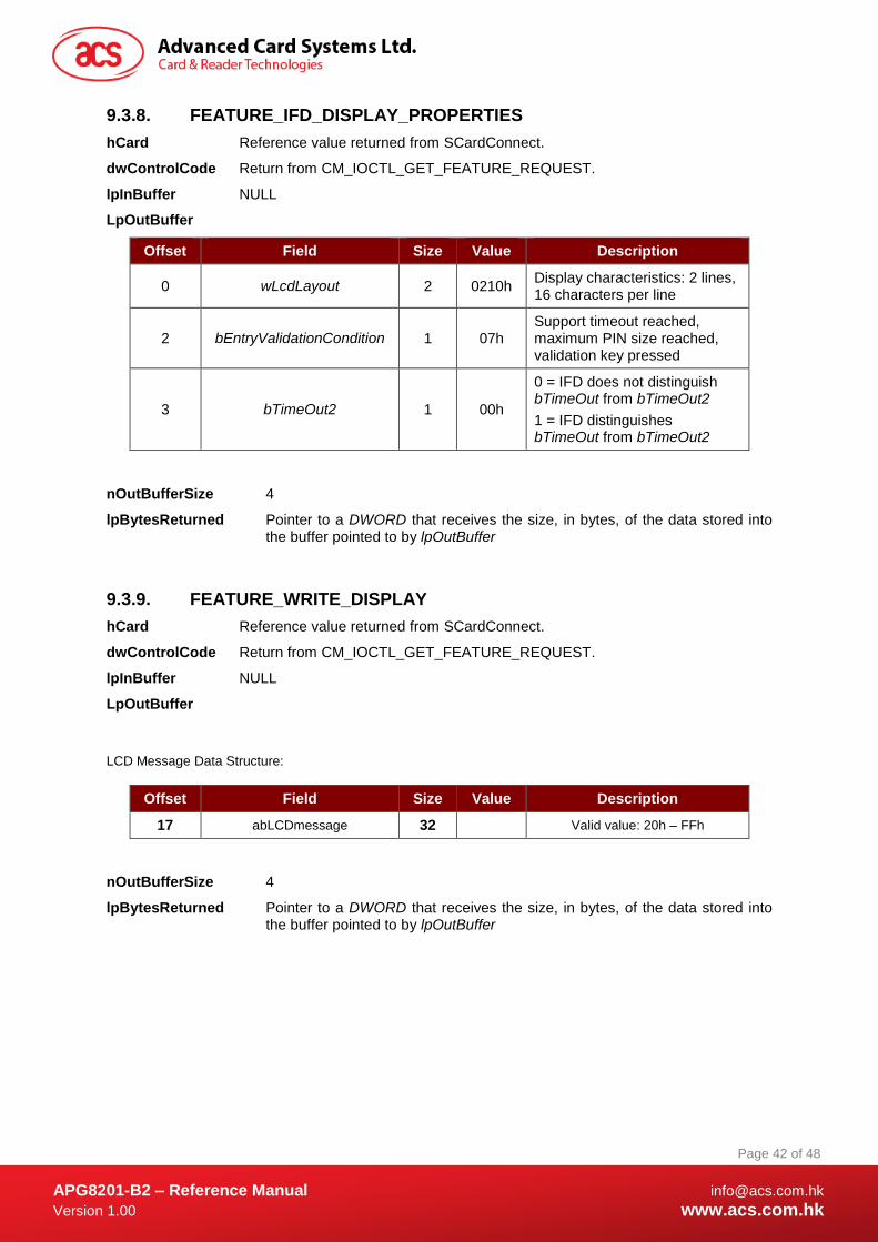
9.3.8. FEATURE_IFD_DISPLAY_PROPERTIES
hCard Reference value returned from SCardConnect.
dwControlCode Return from CM_IOCTL_GET_FEATURE_REQUEST.
lpInBuffer NULL
LpOutBuffer
Offset Field Size Value Description
0 wLcdLayout 2 0210h Display characteristics: 2 lines, 16 characters per line
2 bEntryValidationCondition 1 07h Support timeout reached, maximum PIN size reached, validation key pressed
3 bTimeOut2 1 00h
0 = IFD does not distinguish bTimeOut from bTimeOut2
1 = IFD distinguishes bTimeOut from bTimeOut2
nOutBufferSize 4
lpBytesReturned Pointer to a DWORD that receives the size, in bytes, of the data stored into the buffer pointed to by lpOutBuffer
9.3.9. FEATURE_WRITE_DISPLAY
hCard Reference value returned from SCardConnect.
dwControlCode Return from CM_IOCTL_GET_FEATURE_REQUEST.
lpInBuffer NULL
LpOutBuffer
LCD Message Data Structure:
Offset Field Size Value Description
17 abLCDmessage 32 Valid value: 20h – FFh
nOutBufferSize 4
lpBytesReturned Pointer to a DWORD that receives the size, in bytes, of the data stored into the buffer pointed to by lpOutBuffer

APG8201-B2 – Reference Manual [email protected]
Version 1.00 www.acs.com.hk
Page 43 of 48
www.acs.com.hk
9.3.10. FEATURE_GET_KEY
hCard Reference value returned from SCardConnect.
dwControlCode Return from CM_IOCTL_GET_FEATURE_REQUEST.
lpInBuffer NULL
LpOutBuffer
Read Key Data Options Data Structure:
Offset Field Size Value Description
15 bTimeOut 1
16 wPINMaxExtraDigit 2 YYXXh XX: Minimum PIN size in digit
YY: Maximum PIN size in digit
Valid XX value: 0h – 20h
Valid YY value: 0h – 20h
18 bKeyReturnCondition 1 05h The value is a bit wise OR operation.
01h: Max size reached.
04h: Timeout occurred.
19 bEchoLCDStartPosition 1 Valid value: 0h – 1Fh
20 bEchoLCDMode 1 00h: Echo key press data ASCII representation to LCD.
01h: Display all key presses as asterisks “*” on LCD.
02h: No echo
nOutBufferSize 4
lpBytesReturned Pointer to a DWORD that receives the size, in bytes, of the data stored into the buffer pointed to by lpOutBuffer
APG8201-B2 – Reference Manual [email protected]
Version 1.00 www.acs.com.hk
Page 44 of 48
www.acs.com.hk
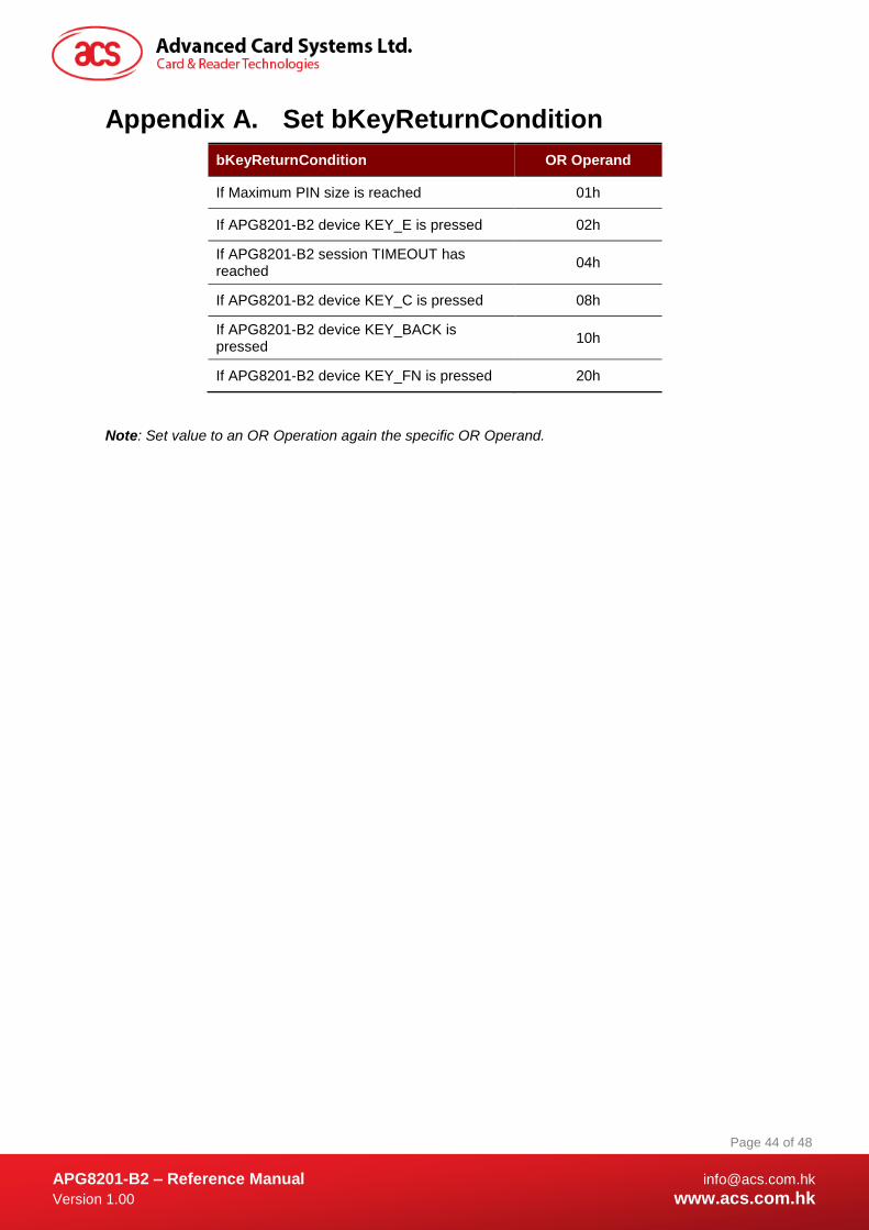
Appendix A. Set bKeyReturnCondition
bKeyReturnCondition OR Operand
If Maximum PIN size is reached 01h
If APG8201-B2 device KEY_E is pressed 02h
If APG8201-B2 session TIMEOUT has reached
04h
If APG8201-B2 device KEY_C is pressed 08h
If APG8201-B2 device KEY_BACK is pressed
10h
If APG8201-B2 device KEY_FN is pressed 20h
Note: Set value to an OR Operation again the specific OR Operand.

APG8201-B2 – Reference Manual [email protected]
Version 1.00 www.acs.com.hk
Page 45 of 48
www.acs.com.hk
Appendix B. Response Error Codes The following table summarizes the possible error code returned by the APG8201-B2 (CCID).
Error Code Status
0001h BAD_PARAMETER
0083h SLOTERROR_LCDCOMMANDERROR
0084h SLOTERROR_WRONGCONFIRMPIN
0085h SLOTERROR_UNKNOWN_LCD
0086h SLOTERROR_MAXPINSIZE_EQUAL_ZERO
00EFh SLOTERROR_PIN_CANCELLED
00F0h SLOTERROR_PIN_TIMEOUT

APG8201-B2 – Reference Manual [email protected]
Version 1.00 www.acs.com.hk
Page 46 of 48
www.acs.com.hk
Appendix C. bmFormatString Description
Bit Number Description
Bit 7
The system units’ type indicator:
If 0h: the system units are bits
If 1h: the system units are bytes
This bit quantifies the next parameter (unit moving).
Bit 6 – 3 Define the PIN position after format in the APDU command (relative to the first data after Lc). The position is based on the system units’ type indicator (maximum 1111 for 15 system units).
Bit 2
Bit mask for the PIN justification:
If 0h: Left justify data
If 1h: Right justify data
Bit 1-0
Bit wise for the PIN format type:
00h: binary
01h: BCD
10h: ASCII

APG8201-B2 – Reference Manual [email protected]
Version 1.00 www.acs.com.hk
Page 47 of 48
www.acs.com.hk
Appendix D. bmPINBlockString Description
Bit Number Description
Bit 7 - 4 Size in bits of the PIN length inserted in the APDU command. (If value is equal to 0h, then the effective PIN length is not inserted in the APDU command)
Bit 3 - 0 PIN length information: PIN block size in bytes after justification and formatting
APG8201-B2 – Reference Manual [email protected]
Version 1.00 www.acs.com.hk
Page 48 of 48
www.acs.com.hk
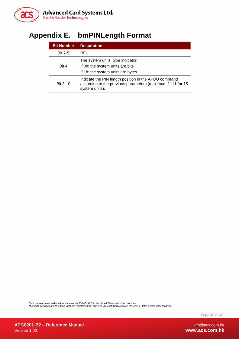
Appendix E. bmPINLength Format
Bit Number Description
Bit 7-5 RFU
Bit 4
The system units’ type indicator:
If 0h: the system units are bits
If 1h: the system units are bytes
Bit 3 - 0 Indicate the PIN length position in the APDU command according to the previous parameters (maximum 1111 for 15 system units).
EMV is a registered trademark or trademark of EMVCo LLC in the United States and other countries. Microsoft, Windows and Windows Vista are registered trademarks of Microsoft Corporation in the United States and/or other countries.