Embed Size (px)
Citation preview

User’s ManualInstallation, Operations,Maintenance and Parts
Part No. 6016083D
Do not install, operate or service this product unless you have read and understand the Safety Practices, Warnings, and Installation and Operating Instructions contained in this User’s Manual. Failure to do so could result in death or serious injury.
This manual applies to fans manufactured beginning January 2016 with the serial number C61174800 and higher.
Apex CommercialHVLS Fans

© Entrematic Group AB 20182 6016083D — Commercial HVLS Fans July 2018
You may find safety signal words such as DANGER, WARNING, CAUTION or NOTICE throughout this User’s Manual. Their use is explained below:
Indicates an imminently hazardous situation which, if not avoided, will result in death or serious injury.
Indicates a potentially hazardous situation which, if not avoided, could result in death or serious injury.
Indicates a potentially hazardous situation which, if not avoided may result in minor or moderate injury.
Notice is used to address practices not related to personal injury.
This is the safety alert symbol. It is used to alert you to potential personal injury hazards. Obey all safety messages that
follow this symbol to avoid possible death or injury.
SAFETY SIGNAL WORDS
Introduction .................................................................2Safety Signal Words ..................................................2Safety Practices..........................................................3Owner’s Responsibilities ............................................4Fan Kit ........................................................................5Hardware ....................................................................6Installation Considerations .........................................7Fan Mount — Suggested Mounting Types .................9Components .............................................................12
TABLE OF CONTENTSInstallation ................................................................13Operating Instructions ..............................................22Planned Maintenance ...............................................27Troubleshooting ........................................................28Fire Control System Fan Shutdown..........................30Parts List...................................................................33Notes ........................................................................36Warranty ...................................................................39Distributor Information ..............................................40
INTRODUCTIONWelcome and thank you for choosing this commercial fan from epic fans
This User's Manual contains basic information that you need to safely install and operate your fan. Please read and keep this User's Manual before using your new fan. For more information, please consult website at www.epicfan.com.

© Entrematic Group AB 2018July 2018 6016083D — Commercial HVLS Fans 3
SAFETY PRACTICES
READ AND SAVE THESE INSTRUCTIONS.
READ THESE SAFETY PRACTICES BEFORE INSTALLING, OPERATING OR SERVICING THE FAN. Failure to follow these safety practices could result in death or serious injury.
READ AND FOLLOW THE OPERATING INSTRUCTIONS IN THIS MANUAL BEFORE OPERATING THE FAN. If you do not understand the instructions, ask your supervisor to teach you how to use the fan.
To reduce the risk of electric shock, do not expose to water or rain.
Support directly from building structure.
To reduce the risk of fire, electric shock and injury to persons, HVLS fan motor assemblies must be installed with the blade assemblies that are marked on their cartons to indicate the suitability with this model. Other blade assemblies cannot be substituted.
To reduce the risk of fire or electric shock, do not use this fan with any solid-state speed control device
Be certain to follow the instructions in this manual.If you do not understand the instructions, ask your supervisor to explain them to you or call your authorized local distributor.
To reduce the risk of injury to persons, install fan so that the blade is at least 3.05m (10') above the floor.
INSTALLATION AND OPERATION:Installation of the equipment must comply with local and national electrical codes and must be in accordance with ANSI/NFPA 70 clauses 400.7 and 400.8.
Do not use this commercial fan until you have received proper training. Improper use could result in property damage, bodily injury and/or death. Read and follow the complete OPERATING INSTRUCTIONS on page 22 before use. If you do not understand the instructions, ask your supervisor to explain them to you or call your local distributor.
DO NOT USE THE FAN IF IT APPEARS DAMAGED OR DOES NOT OPERATE PROPERLY. Inform your supervisor immediately.
Do not operate the fan until all personnel, building structure and moveable equipment are clear of all moving parts. Install guards as required.
Do not install the fan unit onto structure of insufficient strength. Consult a professional engineer or registered architect. Improper installation of the fan could result in death or serious injury.
For fans that will be subjected to high cross winds (open bay doors or air conditioning diffuser ducts) the fan must be at least one fan diameter (as measured from the end of the winglet) from open bays or A/C ducts mounted below the blade plane or there must be at least one fan diameter (as measured from the end of the winglet) for A/C ducts mounted at or above the blade plane.
MAINTENANCE AND SERVICE:
Before service, inspection, or cleaning make certain that the power is disconnected and properly locked off.
If the fan does not operate properly using the procedures in this manual, BE CERTAIN TO REMOVE POWER FROM THE UNIT AND LOCK-OUT THE DISCONNECT ON THE POWER CIRCUIT. Call your local distributor for service.
Keep your body clear of moving parts at all times.
All electrical troubleshooting and repair must be done by a qualified technician and meet all applicable codes.
© Entrematic Group AB 20184 6016083D — Commercial HVLS Fans July 2018
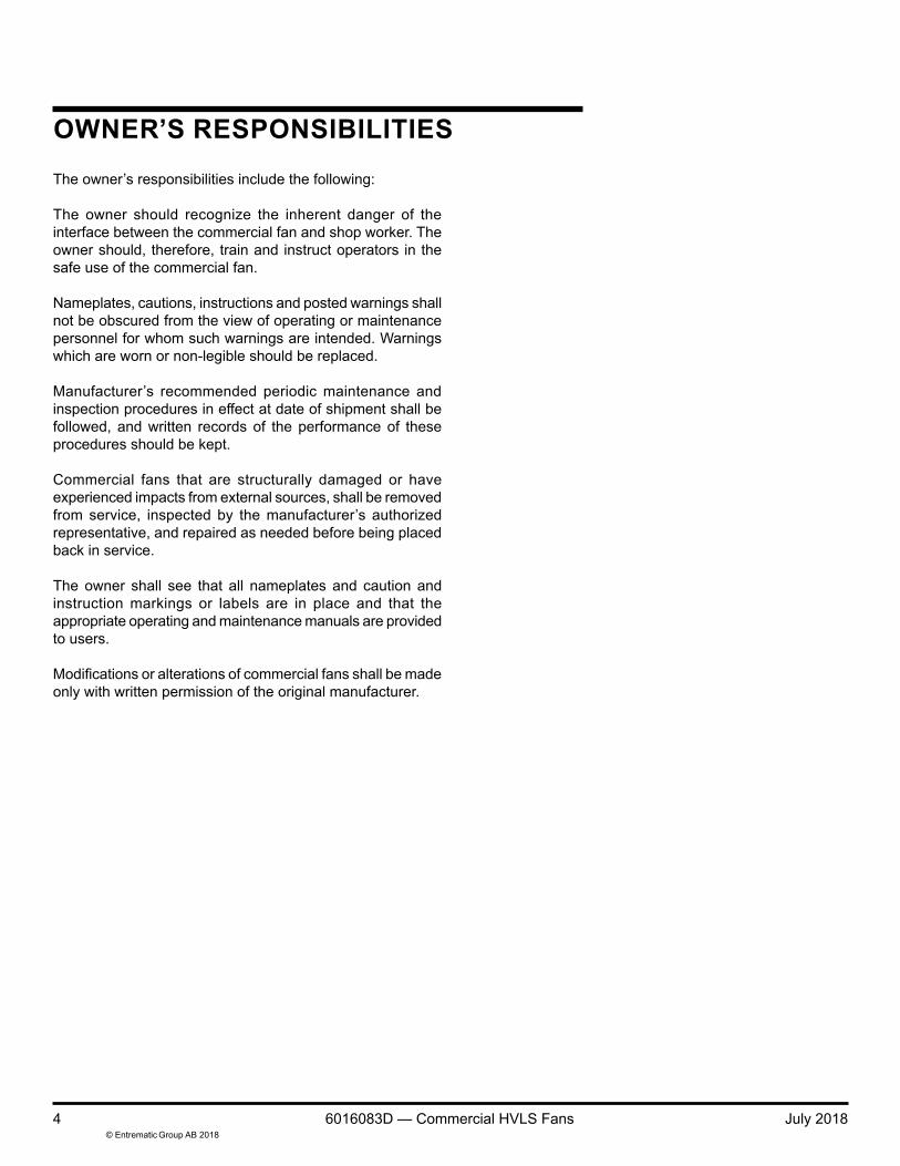
OWNER’S RESPONSIBILITIESThe owner’s responsibilities include the following:
The owner should recognize the inherent danger of the interface between the commercial fan and shop worker. The owner should, therefore, train and instruct operators in the safe use of the commercial fan.
Nameplates, cautions, instructions and posted warnings shall not be obscured from the view of operating or maintenance personnel for whom such warnings are intended. Warnings which are worn or non-legible should be replaced.
Manufacturer’s recommended periodic maintenance and inspection procedures in effect at date of shipment shall be followed, and written records of the performance of these procedures should be kept.
Commercial fans that are structurally damaged or have experienced impacts from external sources, shall be removed from service, inspected by the manufacturer’s authorized representative, and repaired as needed before being placed back in service.
The owner shall see that all nameplates and caution and instruction markings or labels are in place and that the appropriate operating and maintenance manuals are provided to users.
Modifications or alterations of commercial fans shall be made only with written permission of the original manufacturer.
© Entrematic Group AB 2018July 2018 6016083D — Commercial HVLS Fans 5
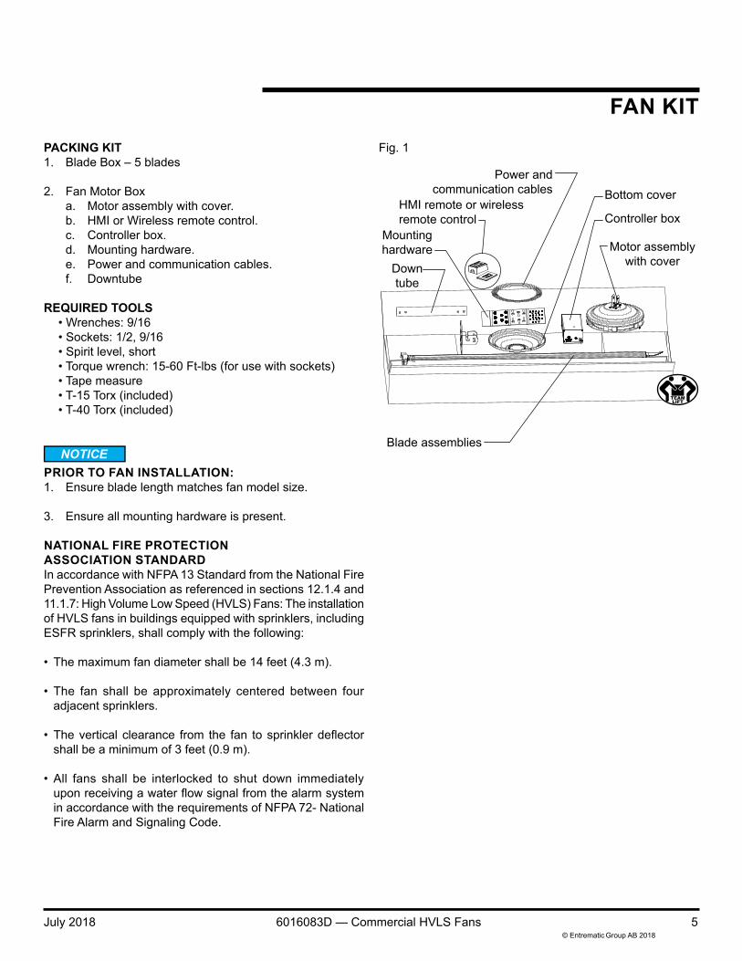
PACKING KIT1. Blade Box – 5 blades
2. Fan Motor Boxa. Motor assembly with cover.b. HMI or Wireless remote control.c. Controller box.d. Mounting hardware.e. Power and communication cables.f. Downtube
REQUIRED TOOLS• Wrenches: 9/16• Sockets: 1/2, 9/16• Spirit level, short• Torque wrench: 15-60 Ft-lbs (for use with sockets)• Tape measure• T-15 Torx (included)• T-40 Torx (included)
PRIOR TO FAN INSTALLATION:1. Ensure blade length matches fan model size.
3. Ensure all mounting hardware is present.
NATIONAL FIRE PROTECTION ASSOCIATION STANDARDIn accordance with NFPA 13 Standard from the National Fire Prevention Association as referenced in sections 12.1.4 and 11.1.7: High Volume Low Speed (HVLS) Fans: The installation of HVLS fans in buildings equipped with sprinklers, including ESFR sprinklers, shall comply with the following:
• The maximum fan diameter shall be 14 feet (4.3 m).
• The fan shall be approximately centered between fouradjacent sprinklers.
• The vertical clearance from the fan to sprinkler deflectorshall be a minimum of 3 feet (0.9 m).
• All fans shall be interlocked to shut down immediatelyupon receiving a water flow signal from the alarm systemin accordance with the requirements of NFPA 72- NationalFire Alarm and Signaling Code.
FAN KITFig. 1
Power andcommunication cables
Motor assemblywith cover
HMI remote or wirelessremote control Controller box
Mountinghardware
Downtube
Blade assemblies
Bottom cover

© Entrematic Group AB 20186 6016083D — Commercial HVLS Fans July 2018
HARDWARE
Fan mount6017852 (x4)Clamp plate
Down tube mount6017748 (x2)
3/8-16UNC x 3-1/4" hex boltgrade 5
serrated head
6015118 (x2)3/8-16UNC hex nut
grade 5serrated head
Motor mount hardware6017838 (x4)
5/16" lock washer
6017835(x4)5/16-18UNC x 3/4" Torx screw
grade 5
6017872 (x1)T40 Torx wrench
Fan mount6017873 (x4)
3/8-16UNC x 2-1/2" hex boltgrade 5
serrated head
6015118 (x4)3/8-16UNC hex nut
grade 5serrated head
Blade hardware6017837 (x10)
5/16-18UNC x 1-3/4" hex boltgrade 5
serrated head
Bottom cover hardware6017870 (x3)
8-32UNC x 1/4" Torx screw
6017871 (x1)T15 Torx wrench

© Entrematic Group AB 2018July 2018 6016083D — Commercial HVLS Fans 7
INSTALLATION CONSIDERATIONS
NOTE:Angle mount has 45° of motion. The extension lengths shown are minimum recommendations only, based solely of roof pitch and fan diameter. Other considerations must be evaluated when determining extension requirements, such as placement of lights, sprinkler systems, HVAC systems, etc. In addition, OSHA requirements state that fan blades must be a minimum of 10' above the floor.
Fig. 2
36" exclusion zone(18" radius)[both sides]
36" min.(to wall)
10' min.(to floor)
Do not mount directly under or within exclusion zone or in line with HVAC supply discharge vent.
Fan Size Extension size (Ft) Max Roof Angle Allowable (degrees)6Ft 1.5 176Ft 2 206Ft 3 356Ft 4 408Ft 1.5 108Ft 2 158Ft 3 258Ft 4 32
10Ft 1.5 1010Ft 2 1210Ft 3 1910Ft 4 2812Ft 1.5 812Ft 2 1012Ft 3 1712Ft 4 2514Ft 1.5 614Ft 2 814Ft 3 1514Ft 4 21

© Entrematic Group AB 20188 6016083D — Commercial HVLS Fans July 2018
INSTALLATION CONSIDERATIONS, continued
PLACEMENT AND SPACINGConsult your local distributor to help you plan the most efficient installation of your fans.
Ensure fan placement is such that the fans blades are a minimum of 10' from any manned working surface (floor or mezzanine)
Ensure fan blade does not extend into exclusion zone. Extensions are available if required. See Fig. 2.
Avoid mounting fans directly under lights or skylights to avoid visual strobing affect.
NOTE:If the fan is part of a networked system, ensure placement is in accordance with the building layout.
NOTE:Be certain to comply with all local and national codes during installation.
For fans that will be subjected to high cross winds (open bay doors, outdoor applications or air conditioning diffuser ducts) the fan must be at least one fan diameter (as measured from the end of the winglet) from open bays or A/C ducts mounted below the blade plane or there must be at least one fan diameter (as measured from the end of the winglet) for A/C ducts mounted at or above the blade plane.
In addition, all outdoor mounted fans must be protected from exposure from the elements. Consult your local distributor for outdoor patio applications.
Do not mount fans to flat ceilings.
NOTE:Fans with long extensions may oscillate at high speeds.

© Entrematic Group AB 2018July 2018 6016083D — Commercial HVLS Fans 9
FAN MOUNT — SUGGESTED MOUNTING TYPES
I-beam
Solid beam
Truss
Z-purlin
I-BEAM MOUNTEDSee page 10 for I-beam mounting instructions.
SOLID BEAM MOUNTEDSee page 10 for solid beam mounting instructions.
TRUSS MOUNTEDSee page 11 for truss mounting instructions.
Z-PURLIN MOUNTEDSee page 11 for Z-purlin mounting instructions.

© Entrematic Group AB 201810 6016083D — Commercial HVLS Fans July 2018
FAN MOUNT — SUGGESTED MOUNTING TYPES, continued
If building support beam is not level, ensure proper fan clearance using the mounting information shown on page 7 or add mounting extensions as required to ensure clearance. See Fig 2.
I-BEAM MOUNTING1. Locate fan centered square to the bottom flange of the
I-beam.
2. Locate and secure the clamp plates (6017852) using theprovided 3/8-16UNC hex serrated flange nuts and 3/8-16UNC X 2 1/2" long bolts. See Fig. 3.
NOTE:Ensure that the clamp plates overlap the I-beam flange by at least 30%.
3. Torque to 20-28 ft-lbs.
SOLID BEAM MOUNTING1. Locate the beam bracket (6018175). Ensure that the
bottom flange of the bracket is below the bottom of thebeam and square to the beam.
NOTE:The vertical flange of the beam bracket must be square with respect to the floor. Shim as required.
2. Using the holes in the beam bracket as a template, markand drill at least four (4) 9/16" dia. holes through the beam.Space the holes as widely as practical. See Fig. 4.
3. Locate both beam brackets with respect to the holes andfasten using 3/8" dia. grade 5 bolts (not provided). Torqueto 20-28 ft-lbs. Locking hardware (nuts and washers)required.
Fig. 3
Fig. 4

© Entrematic Group AB 2018July 2018 6016083D — Commercial HVLS Fans 11
FAN MOUNT — SUGGESTED MOUNTING TYPES, continued
TRUSS MOUNT INSTALLATION
NOTE:The recommended additional structural material for truss mounting is 1-5/8" x 1-5/8" 12 gauge strut channel beams and hardware. Other structural materials may be used but consult factory prior to use.
1. Size the strut channel beams to ensure at least 3" ofoverlap at each end on adjoining building truss members. Do not span more than 6'.
2. Locate the mount bracket at the desired location (centerpreferred) on the strut channel beams and fasten usingthe provided 6017873 and 6015118 3/8" dia. grade 5hardware. Use 6017852 clamp plates as required. Torqueto 20-28 ft-lbs.
3. Locate beam/mount assembly on building truss system.See Fig. 5. (top mounting preferred)
4. Fasten strut channel beams to building truss system using 3/8" dia., grade 5 hardware (not provided). DO NOT usespring loaded strut channel beam hardware. Lockinghardware (nuts and washers) required.
Z-PURLIN MOUNT INSTALLATION – (OPTIONAL KIT 6017945)1. For Z-purlin mounting use 1-5/8" x 1-5/8" 12 gauge strut
channel beams and hardware in addition to purlin clamp,part number P2784, from Unistrut®. Strut to span aminimum of 3 purlins. Consult a structural engineer priorto installation.
2. Attach 2 clamps on each purlin, and loosely secure thestrut channel to the clamps with the u-bolts. See Fig. 6.
3. Locate the mount bracket at the desired location (nearcenter purlin preferred) on the strut channel beams andfasten using the provided 6017873 and 6015118 3/8"dia. grade 5 hardware. Use clamp plates (6017852) asrequired. Torque to 20-28 ft-lbs. See Fig. 6.
4. Ensure strut channel are parallel with each other andperpendicular to purlins. Tighten u-bolts. Torque to 20-28ft-lbs. See Fig. 6.
Fig. 6
Fig. 5

© Entrematic Group AB 201812 6016083D — Commercial HVLS Fans July 2018
COMPONENTS
Fan mount
Controller box(VFD)
Guy wires(if required
see page 18)
Motor assembly
Power/communication
cables
Blade assemblyBottom cover
Down tube
HMI remote
Wirelessremote
(optional)
Fig. 7

© Entrematic Group AB 2018July 2018 6016083D — Commercial HVLS Fans 13
INSTALLATIONDOWN TUBE ASSEMBLY1. Route the power and communication cables through the
down tube.
2. With the down tube located next to the motor assembly,install the cable connections to the top of the motorassembly. See Fig 8. Use the support materials containedin the shipping package to support motor assembly toprevent damage.
3. Install the ground cable connector to the terminal locatedon the top of the motor assembly. Ensure that the cableis oriented to prevent interference with the down tube.See Fig 8.
Ensure proper connection of the power and communication cables. Failure to properly connect the cables can lead to operating issues.
4. Slide the down tube over the motor assembly mount bracketensuring that the cables are not pinched or placed into abind. Align the down tube so that the holes in the downtube align with the holes in the motor assembly mountbracket.
5. Attach the down tube to the motor assembly mount bracketusing the 6017838 5/16" dia. Torx screws and 6017838washers supplied. Tighten the Torx screws using theprovided 6017872 Torx wrench.
Ensure downtubecables are firmly
engaged
Downtubefasteners
Downtube
Motorassembly
Route ground wireto avoid plug
Communicationcable connector
Motor groundfastener
Power cableconnector
Fig. 8

© Entrematic Group AB 201814 6016083D — Commercial HVLS Fans July 2018
HANG THE MOTOR1. In the top hole of the down tube, install a supplied 6017448
3/8" dia. x 3-1/4" bolt and 6015118 nut loosely. Ensurethat the screw does not pinch or bind the power andcommunication cables. See Fig 9.
2. Using the bolt installed in the previous step, hang the motorand down tube assembly on the fan mount. Ensure thatthe power and communication cables are free of bindingor pinching. See Fig 10.
3. Loosely install the second 6017448 3/8" dia. x 3-1/4" boltand nut in the bottom hole at the top of the down tube.Ensure that the bolt does not pinch or bind the power andcommunication cables. See Fig 11.
4. Using a spirit level, ensure that the down tube is plumb.
5. Tighten the 3/8" dia x 3-1/4" bolts to 20-28 ft-lbs.
INSTALLATION, continued
Hang down tubefrom fan mount
Down tube
Top hole
Bottom hole
Power andcommunication cables
(to controller box)
Fig. 9
Fig. 10
Fig. 11

© Entrematic Group AB 2018July 2018 6016083D — Commercial HVLS Fans 15
Ensurecable connectors
are firmly engaged.Power cableCommunication cable
Power cord(to building power)
From fan
INSTALLATION, continued
CONTROLLER INSTALLATION
Before doing any electrical work, make certain the power is disconnected and properly tagged or locked off. All electrical work must be done by a qualified technician and meet all applicable codes. USE EXTREME CAUTION. Touching wires could result in electrical shock, death or serious injury.On 120V fan, never allow more than 130 volts incoming power to be connected to the controller box. Damage to the fan and serious personal injury or death may result.
DO NOT place VFD inside another enclosure.
NOTE:The controller box should be located outside of the blade arc where possible and oriented such that the connections at either end are accessible.
1. Install the controller box to building structure such that the box is secure against movement. Fasteners not included.
2. Route the power and communication cables from the fanmounting location to the controller box. Ensure that thecables are routed clear of the fan blades and supportedthroughout their run.
3. Connect the power and communication cables from thefan to the controller box. See Fig. 12.
Ensure proper connection of the power and communication cables. Do not alter factory supplied cables. Failure to properly connect the cables can lead to operating issues.
4. Connect controller box power cord to building power. See Fig. 13.
NOTE:If fire alarm option is not being used, ensure fire alarm jumper is in place to ensure proper operation. See page 30.
Building power
Power cord(from controller box)
Line
Neutral
Ground
Fire alarm jumper
Fig. 12
Fig. 13
Fig. 14

© Entrematic Group AB 201816 6016083D — Commercial HVLS Fans July 2018
INSTALL BLADES1. Position mounting end of blade assembly in an open
blade pocket on the motor assembly rim as shown.Angle the blade approximately 45° downward and rotatedapproximately 15° forward. See Fig 15. This will positionthe forward tang of the blade mount between the two steel mount rings on the motor assembly.
2. Rotate the blade backward and upward to allow the mountend of the blade to slide into the blade pocket on the motorassembly rim. Position the forward tang of the mount inthe forward end of the blade pocket.
3. Rotate in the same plane as the hub to seat the blademount into the blade pocket.
4. Insert two 6017837 5/16" dia x 1-3/4" long fastenersfrom below through the hub mount ring and blade mount.Tighten enough to hold the blade in place but do not fullytighten at this time.
5. Repeat installation steps 1 through 4 for each of theremaining blades.
6. Fully torque the blade mount fasteners to 12-17 ft-lbs.
INSTALLATION, continued
Install boltsthrough
bottom ofhub and
tighten with1/2" socket.Torque to
12-17 ft-lbs.
Insert bladetab at an angle.
Rotate untilblade tabclicks inplace.
Slide tab inand to left.
Tang Blade pocket
Fig. 15

© Entrematic Group AB 2018July 2018 6016083D — Commercial HVLS Fans 17
INSTALLATION, continued
Bottom cover
INSTALL BOTTOM COVER1. Align the mounting holes on the bottom cover with the
mounting holes on the motor assembly. Install the three6017870 #8 dia Torx fasteners supplied. Firmly tightenthe fasteners using the 6017871 Torx tool provided. SeeFig 16.
Fig. 16

© Entrematic Group AB 201818 6016083D — Commercial HVLS Fans July 2018
45°
45°
Clamp bracket2/3 down frommounting bracket
To loosen, insert the thin rod provided into the end of the clamp. While gripping the clamp and pressing the rod into the clamp, pull on the cable end.
INSTALLATION, continued
OPTIONAL GUY WIRE KIT (6016307)
NOTE:Guy wires are required on all fan installations where the down tube is greater than 4' in length. Guy wires are designed to constrain lateral movement of the fan while in operation. This movement may be due to impacts on the fan or winds impinging on the blades that would cause the fan to sway.
Failure to attach guy wires may result in loss of warranty.
Ensure that the proper guy wire length is accompanying the extension used. Ensure that the angle formed by the guy wire with the roof structure is less than 45 degrees. See Fig 17. Avoid any sharp edges or corners to reduce fatiguing and fraying of the guy wires. Failure to attach guy wires may result in severe injury or death.
1. Remove parts from package and inventory. Package contentsinclude: 4 cables, 4 gripple cable clamps, 2 5/16-18 x 1"serrated flanged hex hardware, 2 guy wire clamp bracketsand 1 Gripple release tool.
2. Locate the down tube clamp bracket on the down tube. Theclamp bracket should be located approximately 2/3 downbetween the mounting bracket and the motor assembly.
3. Fasten the halves of the down tube clamp bracket with the5/16" dia x 1" carriage bolts supplied. Torque to 12-17 ft-lbs.
4. Attach each cable to the building structure by either loopingthe cable through the cable eyelet and around a beam/truss orother secure building structure (preferred method) or by using3/8" dia. grade 5 fasteners and lock-washers (not provided)to secure to structure. Tighten fasteners to 20-28 ft-lbs.
5. On each cable assembly, slide one Gripple cable clampapproximately 12" on the cable. See Fig 17.
6. Loop one cable assembly through each lug on the down tube clamp bracket using the free end of the cable.
7. Thread the free end of each cable assembly back throughthe Gripple cable clamp. Leave loose.
8. Using a spirit level on the down tube, tighten the cableassemblies by pulling the cable through the Gripple cableclamp as required to achieve a taut cable set while maintaining the down tube plumb. Either secure the loose cable ends ortrim.
Fig. 17

© Entrematic Group AB 2018July 2018 6016083D — Commercial HVLS Fans 19
INSTALLATION, continued
INSTALL HMI REMOTE CONTROL
Do not over-torque mounting screws. Damage to display screen may occur if mounting screws are over-torqued. It is the installer’s responsibility to torque properly.
1. Mount touch screen remote to factory supplied junction boxinside building as close to the fan assembly as practical.Direct line of sight is preferred. See Fig 18.
NOTE:The remote signal cable (6020562) has terminated ferrules at each end. PROTECT these ferrules during cable routing.
2. Route the remote signal cable (6020562) from the VFDbox, through the hole in the factory supplied junction boxand wire the 3 leads of the remote signal cable to theorange connector of the touch screen remote control.Excess cable length should be neatly coiled and securednear VFD box.
3. Mount the touch screen to the junction box using thefasteners provided.
NOTE:For cable runs exceeding 1000', consult factory.
VERIFY OPERATION — HMIOperate the commercial fan following the operating instructions in this manual. Check for proper rotation direction, stability and noise level.
Train authorized personnel how to use the commercial fan using the operating instructions in this manual.
Touch screen
1/2 NPT port
Junction box
F.G
.VD
CG
ND
Dat
a+D
ata-
Plug
V+ V-
Note: Jumperneeds to be inplace for MODBUScommunication
Jumper
N L
Belden 8723or equivalent(Supplied by
others)
24VDC power supply
BlueBlackRed
Brown
Fig. 18

© Entrematic Group AB 201820 6016083D — Commercial HVLS Fans July 2018
INSTALLATION, continued
INSTALLING THE WIRELESS REMOTE (OPTIONAL)1. The fan remote may be mounted directly into a standard
wall junction box or directly to a wall surface using mounting tape. Locate the remote within 50' of the fan. See Fig 19.
NOTE:A clear sight line between the fan and the remote is preferred in order to maximize the remote's effective distance.
Wallplateadapter Wallplate
‘snap’
Fig. 19

© Entrematic Group AB 2018July 2018 6016083D — Commercial HVLS Fans 21
INSTALLATION, continued
PROGRAMMING THE WIRELESS REMOTE
NOTE:The fan ships from the factory with the remote pre-programmed and ready to use. To program or reprogram the remote, access to the controller box will be required. Ensure that the fan is not running and there is power to the controller box.
1. Locate the controller box and ensure that there is accessto the top cover.
2. On the top cover, locate the remote program access hole. See Fig 20.
3. With a small dowel or other blunt object, gently depress theprogramming button for 10 seconds and then immediately perform step 4.
4. On the remote, press and hold the power off button for 6seconds. Release the button when the green LED on theremote begins to flash to show that the wireless remotehas been associated with the controller. See Fig 21.
CHANGING THE BATTERY IN THE WIRELESS REMOTE
Burn hazard. To avoid the risk of fire, explosion or burns, DO NOT recharge, disassemble, crush, puncture or incinerate the battery. DO NOT heat the battery above 212°F (100°C).
NOTE:A dead battery must be replaced promptly in order to retain programming.
1. Remove the wireless remote from the faceplate assembly.
2. Place a flathead screwdriver into the slot at the bottom ofthe remote. Twist to open. DO NOT press buttons without back enclosure on. See Fig. 22.
3. Slide the battery out, toward the top of the remote.
4. Slide a new CR 2032 battery underneath the contact strap,with the (-) terminal toward the front of the remote.
5. Replace the back enclosure.
6. Ensure proper fan operation. If the remote fails to controlthe fan, re-program the remote using the process describedabove.
7. Re-install remote into faceplate as required.
Fig. 20
Fig. 21
Fig. 22
CR 2032 battery
Programaccess hole
Controller box Circuit breaker
Power off
Green LED

© Entrematic Group AB 201822 6016083D — Commercial HVLS Fans July 2018
OPERATING INSTRUCTIONS — HMI, continued
Fig. 23
Start/Stop
RPM increase
Reverse
Communication status (Green - Comm)
(Black - No Comm)
Forward
Diagnosticscreen
RPM decrease
14Software version Fan diameter

© Entrematic Group AB 2018July 2018 6016083D — Commercial HVLS Fans 23
OPERATING INSTRUCTIONS — HMI, continued
Fig. 24
Before operating the commercial fan , read and follow the Safety Practices, Warnings and Operating Instructions in this manual. Use by untrained personnel could result in death or serious injury.
VERIFY PRIOR TO OPERATION1. Voltage/phase.
2. Obstruction clearance.
3. Safety cables present and properly installed.
4. All fasteners are properly torqued.
STARTING THE FANVisually inspect the fan to ensure that there are no obstructions or personnel in the movement area.
LOGIN SCREENIf the password has been enabled, you must log in before operating the fan.
NOTE:Default password: 1111
NORMAL OPERATION1. Verify normal communication — the communication status
symbol in bottom lefthand corner will be green.
2. Press the Start button and select fan direction to beginfan rotation.
3. Set desired speed by pressing either RPM increase orRPM decrease until desired speed is displayed. Maximumspeed is 10, minimum speed is 1. See Fig. 24.
Fan speed
© Entrematic Group AB 201824 6016083D — Commercial HVLS Fans July 2018
OPERATING INSTRUCTIONS — HMI, continued
Fig. 26
CHANGING DIRECTION1. Select either Forward or Reverse. It is not necessary to
stop the fan first.
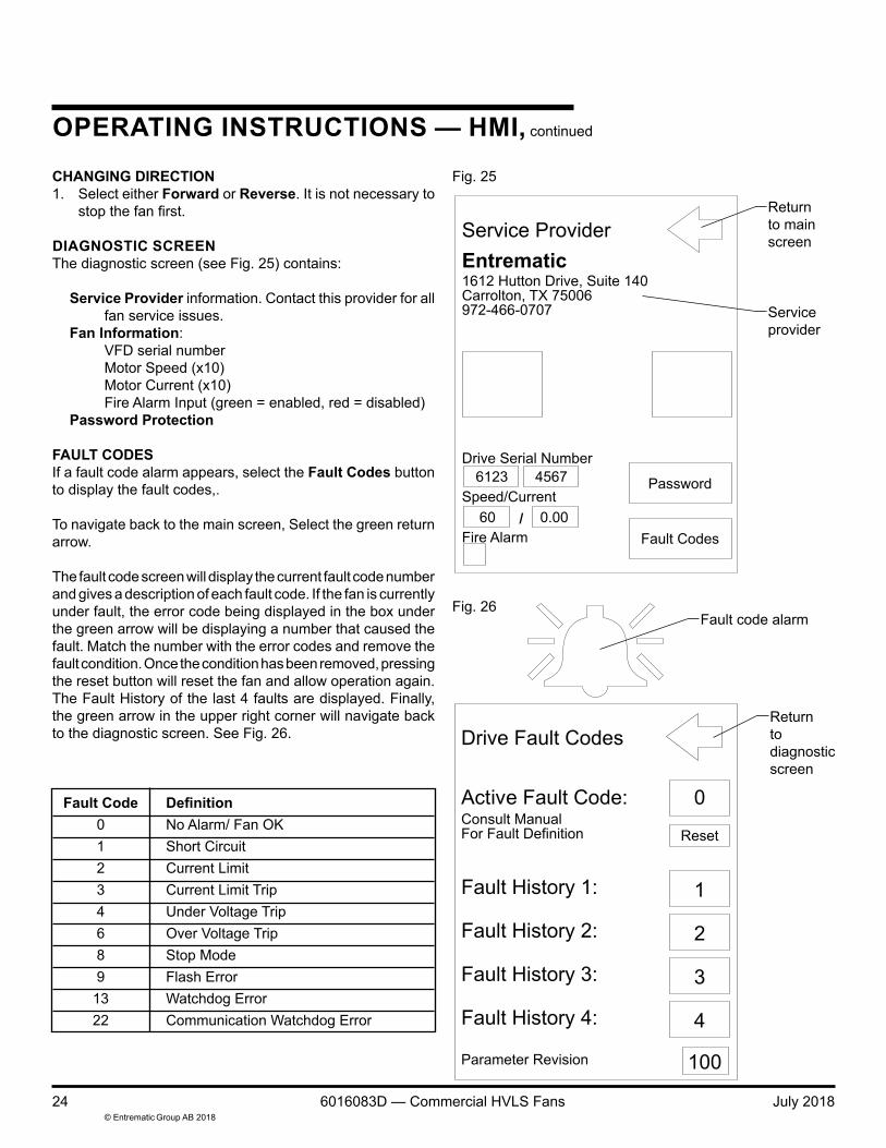
DIAGNOSTIC SCREENThe diagnostic screen (see Fig. 25) contains:
Service Provider information. Contact this provider for all fan service issues.
Fan Information:VFD serial numberMotor Speed (x10)Motor Current (x10)Fire Alarm Input (green = enabled, red = disabled)
Password Protection
FAULT CODESIf a fault code alarm appears, select the Fault Codes button to display the fault codes,.
To navigate back to the main screen, Select the green return arrow.
The fault code screen will display the current fault code number and gives a description of each fault code. If the fan is currently under fault, the error code being displayed in the box under the green arrow will be displaying a number that caused the fault. Match the number with the error codes and remove the fault condition. Once the condition has been removed, pressing the reset button will reset the fan and allow operation again. The Fault History of the last 4 faults are displayed. Finally, the green arrow in the upper right corner will navigate back to the diagnostic screen. See Fig. 26.
FaultCode Definition 0 No Alarm/ Fan OK
1 Short Circuit2 Current Limit3 Current Limit Trip4 Under Voltage Trip6 Over Voltage Trip8 Stop Mode9 Flash Error
13 Watchdog Error 22 Communication Watchdog Error
Returntodiagnosticscreen
Fault code alarm
Fig. 25
Returnto mainscreen
Serviceprovider

© Entrematic Group AB 2018July 2018 6016083D — Commercial HVLS Fans 25
OPERATING INSTRUCTIONS — HMI, continued
PASSWORD PROTECTIONThe remote is capable of password protection to prevent unauthorized use.1. Press the diagnostic screen button from the main screen.
2. Press the Password button on the diagnostic screen.
NOTE:If the password has already been previously customized, enter it now. If not, the default password: 1111
On the password screen, the options are to enable the password, disable the password and change the password. By default, the password is not enabled.
To enable password, touch the unlocked padlock icon. The padlock icon will switch from unlocked to locked.
To disable password, touch the locked padlock icon. The padlock icon will switch from locked to unlocked.
UPDATING PASSWORD1. Enter the desired password using the numeric keypad.
2. Press the Update Password button. See Fig. 27.
NOTE:When the password is enabled, the unit will automatically log out after 2 minutes. To return to diagnostic screen, select green return arrow.
Fig. 27

© Entrematic Group AB 201826 6016083D — Commercial HVLS Fans July 2018
OPERATING INSTRUCTIONS — WIRELESS REMOTEFig. 28
Before operating the fan, read and follow the Safety Practices, Warnings and Operating Instructions in this manual. Use by untrained personnel could result in death or serious injury.
VERIFY PRIOR TO OPERATION1. Power supplied to fan.
2. Obstruction clearance.
3. Safety cables (optional) properly installed.
4. All fasteners are properly torqued.
STARTING THE FAN
NOTE:Pressing the POWER ON button once, while the fan is running will set fan to full speed.
Visually inspect the fan to ensure that there are no obstructions or personnel in the movement area.
1. Press the FAVORITE button. The fan will start and spinup to approximately 2/3 full speed.
2. Adjust the speed by pressing either the INCREASE SPEEDor DECREASE SPEED buttons. Each press of the buttonswill adjust the fan speed by approximately 5%.
STOPPING THE FAN
1. Press the POWER OFF button once to stop the fan.
PROGRAMMING THE FAVORITE BUTTON
NOTE:The fan ships from the factory with the FAVORITE button pre-programmed to approximately 2/3 full speed.
1. With the fan running, adjust the speed of the fan usingeither the INCREASE SPEED or DECREASE SPEEDbutton to achieve desired speed. See Fig. 28.
2. Once desired speed is achieved, press and hold theFAVORITE button for 10 seconds. This speed nowbecomes the new FAVORITE speed.
CHANGING DIRECTION1. The fan direction control is located on the top of the motor
assembly. To reverse direction, stop the fan and press the button. See Fig. 29.
Power on
Green LED
Increase speed
Favorite button
Decrease speed
Power off
Fig. 29
Fan direction controland status light

© Entrematic Group AB 2018July 2018 6016083D — Commercial HVLS Fans 27
PLANNED MAINTENANCE
Before service, inspection, or cleaning make certain that the power is disconnected and properly locked off.
Before servicing the fan, read and follow the Safety Practices on page 3 and the Operation section in this manual. Failure to do so could result in death or serious injury.
To ensure the continued proper operation of your fan, perform the following planned maintenance procedures.
ANNUALLY1. Inspect blade mounting hardware and tighten as required.
Torque to 20-28 ft-lbs.
2. Inspect guy wires for chaffing or wear. Ensure wires aretaut. Re-tighten cables as required and ensure all cablemounting hardware is secure. Maintain plumb attitude ofdowntube. Torque to 12-17 ft-lbs.
3. Inspect fan blades and winglets. Clean fan blades asrequired. Use a soft dry cloth. If necessary, use a milddetergent to clean surfaces. Do not use harsh cleansers.
Fig. 30
LegendSymbol Description
Cleaning(Location - Frequency)
Visually Inspect(Replace Damaged Or Worn)
Check Fasteners(Torque to spec. if necessary)

© Entrematic Group AB 201828 6016083D — Commercial HVLS Fans July 2018
TROUBLESHOOTING
Before servicing the fan, read and follow the Safety Practices on page 3 and the Operation section in this manual. Failure to do so could result in death or serious injury.
Use the Troubleshooting Guide if the fan fails to perform properly. Find the condition that most closely matches your situation and make the recommended adjustments.
Before service, inspection, or cleaning make certain that the power is disconnected and properly locked off. Before doing any electrical work, make certain the power is disconnected and properly locked or tagged off. Failure to do so may result in death or serious injury. All electrical troubleshooting and repair must be done by a qualified technician and meet all applicable codes. Failure to do so could result in electrical shock, death or serious injury.
1. No blue light, no fan movement
2. Fast blink (approx. 2 blinks/sec.)blue light, no fan movement
3. Fast blink blue light, fanmovement.
4. Slow blink blue light, nomovement
5. Solid blue light, sustainedshuddering movement
6. Fan runs but makes noise orvibrates
a) No power to fan
b) Circuit breaker on controllerbox tripped
c) Communication cable loose
d) Wireless remote is notprogrammed
e) Bad wireless remote
f) Issue inside controller box
a) Power cable loose
a) Bad communication cable
b) Encoder cable loose
c) Motor power lead loose
d) Issue inside controller box
a) Fire alarm jumper issue
a) Issue inside controller box
a) Bad motor bearing
b) Missing or damaged winglet
c) Loose or damaged blade
d) Loose or damaged guywires
a) Check incoming power
b) Reset circuit breaker See Fig. 20.
c) Ensure communication cable is firmlyattached at each end.
d) Program wireless remote. See page 21.
e) Replace and program new wirelessremote
f) Consult technical service
a) Ensure power cable is firmly attached ateach end
a) Replace cable
b) Consult technical service
c) Consult technical service
d) Consult technical service
a) Ensure jumper wire is in place
a) Consult technical service
a) Check if fan rotates freely by handwithout binding
b) Check winglets
c) Ensure blades are firmly attached andmounting fasteners are tight
d) Ensure guy wires are taut and properlyinstalled
Problem Possible Cause Solution

© Entrematic Group AB 2018July 2018 6016083D — Commercial HVLS Fans 29
TROUBLESHOOTING
Problem Possible Cause Solution
7. Fan does not operate.
8. Fan does not operate. Controlpanel has power.
9. Fan operating, but showsexcessive wobble.
10. Fan generating a ticking noise,tick increases with speed.
a) No power to control panel.
b) Circuit breakers tripped.
a) Obstructions preventingmovement.
b) Remote not properlyconnected
c) VFD faulted.
d) Fire circuit open.
a) Guy wires not tensionedproperly.
b) Winglet missing.
a) Blades bolts not properlytightened.
a) Ensure that the disconnect is in the onposition. Check for primary power atterminals
b) Reset circuit breaker.
a) Check fan unit, ensure there are noobstructions preventing movment.
b) Check connections between remote/VFD.
c) Check for VFD fault. Check fault codeaction - reset drive. (power off/power on)
d) RED fire alarm indicator = fire alarmis active or fire alarm circuit is open.Review building fire system and reset ifnecessary
a) Re-tension guy wires in accordance withthe installation instructions on page 18.
b) Replace winglet.
a) Loosen the the blade nuts. Support theblade level (horizontally) before torquingthe bolts to 12-17 ft-lbs.

© Entrematic Group AB 201830 6016083D — Commercial HVLS Fans July 2018
This fan includes a fire alarm jumper for a building fire control systems option that allows the fan to be shut down by the fire control system in case of a fire emergency.
NOTE:Ensure that the fire alarm jumper is in place or the building fire control system is connected and jumper removed.
1. The normally closed (NC) contacts must be dry contacts.They open in the event of an active fire alarm.
2. The fire control system fan shutdown option is notenabled when shipped. To enable the fire control systemfan shutdown option, remove jumper and route a pair ofconductors to a set of customer supplied N.C. contactsin the building's fire alarm panel. See Fig. 31.
3. To test the fire control system fan shutdown operationremove the wire from the NC contact at the building firecontrol panel. The fan should coast to a stop.
If the jumper is left installed the fan will not shut down due to fire control system contacts.
FIRE CONTROL SYSTEM FAN SHUTDOWN — OPTIONAL
Fire alarm jumper
Fig. 31

© Entrematic Group AB 2018July 2018 6016083D — Commercial HVLS Fans 31
FIRE CONTROL SYSTEM FAN SHUTDOWN — OPTIONAL, continued
Fig. 32
FIRE CONTROL SYSTEM FAN SHUTDOWN PANEL — STANDARD INSTALLATION (6015291)
Before doing any electrical work, make certain the power is disconnected and properly locked or tagged off. Failure to do so may result in death or serious injury. All electrical troubleshooting and repair must be done by a qualified technician and meet all applicable codes. Do not route control wiring for any other device through this control box. Be certain power is off when wiring to the control box. Failure to do so could result in electrical shock, death or serious injury.

© Entrematic Group AB 201832 6016083D — Commercial HVLS Fans July 2018
FIRE CONTROL SYSTEM FAN SHUTDOWN — OPTIONAL, continued
Fig. 33
FIRE CONTROL SYSTEM FAN SHUTDOWN PANEL — NETWORK INSTALLATION (6020547)
DELTA

© Entrematic Group AB 2018July 2018 6016083D — Commercial HVLS Fans 33
Fig. 35
PARTS LIST — HMI REMOTE
Item Quantity Part Description Part Number1 1 6020339TOUCH SCREEN CONTROLLER
TOUCH SCREEN CONTROLLER — MULTI FAN REMOTE, Epic fans 6020585
2 1 J-BOX , PLASTIC, IVORY 6015648
3 1 CABLE CAT5, 100' W/ FERRULE (BLUE) 6020562
4 1 POWER SUPPLY, 24V, 8A, UNIV INPUT 6021099
WHT/BRNBRN
WHT/GRN
See page 19for wiring detail
2
1
3
F.G
.VD
CG
ND
Dat
a+D
ata-
4

© Entrematic Group AB 201834 6016083D — Commercial HVLS Fans July 2018
PARTS LIST — FAN
2 1
9
12
811
3
14
7
4
10
6
5
21
18
1315
19
2017 16
Fig. 34
To ensure proper function, durability and safety of the product, only replacement parts that do not interfere with the safe, normal operation of the product must be used. Incorporation of replacement parts or modifications that weaken the structural integrity of the product, or in any way alter the product from its normal working condition at the time of purchase from Epic Fans may result in product malfunction, breakdown, premature wear, death or serious injury.

© Entrematic Group AB 2018July 2018 6016083D — Commercial HVLS Fans 35
PARTS LIST — FAN, continued
Item Quantity Description Part Number1 1 MOUNT, 45° 6018002
2* 1 UPPER COVER - SILVER 6016269
3* 1 LOWER COVER - SILVER 6017786
4 1 CONTROLLER CONSULT FACTORY
5 1 POWER CABLES - 600" 6020571
6 1 CONTROL CABLES - 600" 6021114
7 1 BEAM MOUNT — OPTIONAL 6018175
8* 1 DOWN TUBE - SILVER - 18" 6017726
9* 1 BLADE ASSEMBLY — 6FT - SILVER 6017580BLADE ASSEMBLY — 8FT - SILVER 6017581BLADE ASSEMBLY — 10FT - SILVER 6017582BLADE ASSEMBLY — 12FT - SILVER 6017583BLADE ASSEMBLY — 14FT - SILVER 6017584
10 1 WIRELESS REMOTE — (OPTIONAL) 6016233
11 1 MOTOR ASSEMBLY 6016280
12 1 CEILING COVER PLATE 6017848
13 4 3/8-16UNC X 2 1/2", FLNG SERTD HEX BOLT, GRD-5 6017873
14 1 EXTENSION GUY WIRE KIT, 3-5' 6016307EXTENSION GUY WIRE KIT, 5-10' 6017765EXTENSION GUY WIRE KIT, 10-15' 6017766
15 2 3/8-16UNC X 3 1/4", FLNG SERTD HEX BOLT, GRD-5 6017748
16 3 8-32UNC X1/4 LG FLT HD SCREW-TORX, ZP 6017870
17 10 5/16-18UNC X 1 3/4", FLGD SRTD HEX BOLT,GRD-5, ZP 6017837
18 6 3/8-16UNC HEX SERRATED FLANGE NUT 6015118
19 4 5/16-18UNC X 3/4 LG TORX SOC HD SCREW, GRD 2, ZP 6017835
20 4 5/16 INT TOOTH LOCK WASHER 6017838
21 4 CLAMP PLATE, COMM FAN 6017852
*Consult factory for colors other than silver.

© Entrematic Group AB 201836 6016083D — Commercial HVLS Fans July 2018
NOTES

© Entrematic Group AB 2018July 2018 6016083D — Commercial HVLS Fans 37
NOTES

© Entrematic Group AB 201838 6016083D — Commercial HVLS Fans July 2018
NOTES

© Entrematic Group AB 2018July 2018 6016083D — Commercial HVLS Fans 39
WARRANTYTHIS LIMITED WARRANTY IS Epic Fan’s SOLE AND EXCLUSIVE WARRANTY WITH RESPECT TO THE HVLS FAN AND IS IN LIEU OF ANY OTHER GUARANTEES OR WARRANTIES, EXPRESS OR IMPLIED. THIS LIMITED WARRANTY APPLIES ONLY TO THE ORIGINAL PURCHASER OF THE HVLS FAN AND CANNOT BE TRANSFERRED.
Epic Fans warrants that this HVLS FAN will be free from flaws in material and workmanship under normal use for a period of one (1) year from the earlier of 1) 60 days after the date of initial shipment by Epic Fans, or 2) the date of installation of the HVLS FAN by the original purchaser, provided that the owner maintains and operates the HVLS FAN in accordance with this User's Manual.
In the event that this HVLS FAN proves deficient in material or workmanship within the applicable Limited Warranty period, owner shall so notify Epic Fans, and Epic Fans will, at its option:
1. Replace the HVLS FAN, or the deficient portion(s) thereof, without charge to the owner; or
2. Alter or repair the HVLS FAN, on site or elsewhere, without charge to the owner.
In addition, Epic Fans warrants the HVLS FAN for an additional nine (9) years for replacement parts only.
This Limited Warranty does not cover any failure caused by improper installation, abuse, improper operation, negligence, or failure to maintain and adjust the HVLS FAN properly. Parts requiring replacement due to damage resulting from impact, abuse, or improper operation are not covered by this warranty. Epic Fans DISCLAIMS ANY RESPONSIBILITY OR LIABILITY FOR ANY LOSS OR DAMAGE OF ANY KIND (INCLUDING WITHOUT LIMITATION, DIRECT, INDIRECT, CONSEQUENTIAL OR PUNITIVE DAMAGES, OR LOST PROFITS OR LOST PRODUCTION) arising out of or related to the use, installation or maintenance of the HVLS FAN (including premature product wear, product failure, property damage or bodily injury resulting from use of unauthorized replacement parts or modificationoftheHVLSFAN).ENTREMATIC’ssoleobligationwithregardtoaHVLSFANthatisclaimedtobedeficientinmaterialorworkmanshipshallbeassetforthinthisLimitedWarranty.ThisLimitedWarranty will be null and void if the original purchaser does not notify ENTREMATIC’s warranty department within ninety(90)daysaftertheproductdeficiencyisdiscovered.
THERE ARE NO WARRANTIES, EXPRESS OR IMPLIED, WHICH EXTEND BEYOND THE DESCRIPTION ON THE FACE HEREOF, INCLUDING, BUT NOT LIMITED TO, A WARRANTY OF MERCHANTABILITY OR OF FITNESS FOR A PARTICULAR PURPOSE, ALL OF WHICH Epic Fans HEREBY DISCLAIMS.
Warranty and Factory Service Request
Procedure
Epic Fans HVLS Warranty Request
Your local distributor is:
Please direct questions about your fan to your local distributor.
Corporate Head Office:
1612 Hutton Dr. Suite 140Carrollton, TX. 75006Tel. (972) 466-0707Fax (972) 323-2661
Part No. 6016083D© Entrematic Group AB 2018