Embed Size (px)
Citation preview
Aperflux 851Pressure Regulators
Aperflux 851
Pressure Regulators
DESIGNEDWITH YOURNEEDS IN MIND
- COMPACT DESIGN - OUTSTANDING TURN DOWN RATIO- EASY MAINTENANCE - HIGH ACCURACY- TOP ENTRY - LOW OPERATION COST- LOW NOISE - ExTREME FLExIbILITY
Aperflux 851 is a pilot-controlled pressure regulator for medium and high pressure applications.Aperflux 851 is normally a failed open regulator that will open under the following conditions:- breakage of main diaphragm;- lack of pressure feeding to the pilot loop.This regulator is suitable for use with previously filtered, non-corrosive gases.
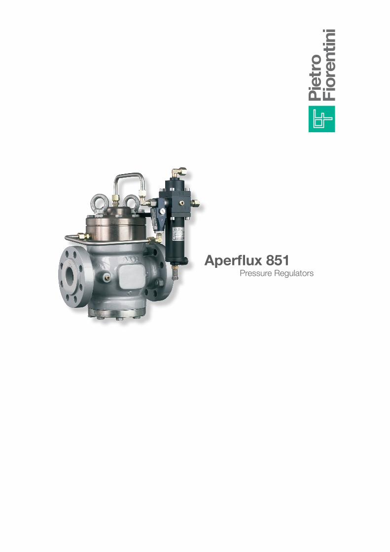
The modular design of Aperflux 851 pressure regulators allows retrofitting of an emergency monitor PM/819, slam shut valve and or silencer on the same body.The Aperflux 851 regulator is truly a “top entry design” which allows ease of maintenance and retrofitting options in the field. The unique dynamic balancing system ensures an outstanding turn-down ratio combined with an extreme accurate outlet pressure control.
Modular Design
Aperflux 851 + DB
Fig. 1Fig. 2
Low Noise
Aperflux 851 is equipped, in standard configuration, with a double cage system. The first cage is designed to optimize the opening / Cg ratio, creating the base for the outstanding 500:1 turndown for this regulator. The second cage is designed to reduce noise emissions, resulting in lower noise than similar products equipped with an additional silencer. For extra low noise installation the additional silencer DB is always available.
Aperflux 851
SLAM SHUT Sb82 OR Hb/97 Aperflux 851
SILENCER Db/851 Aperflux 851
With decibel noise limitations and problems becoming an increasing safety concern, the DB silencer option is a unique feature that reduces regulator noise. When the DB silencer is used, it allows you to considerably reduce the noise level (dBa) up to 30 dBa, depending upon the application. The Aperflux 851 pressure regulator can be supplied with an incorporated silencer in either the standard version or version with incorporated slam-shut or incorporated monitor regulator. With the built-in silencer, the Cg and KG valve coefficients are 5% lower than the corresponding version without the silencer. With this modular feature of the regulator, the silencer may be retrofitted to both standard Aperflux 851 version as well as those with incorporated slam-shut or monitor, without any need for piping modification.Pressure reduction and control operate in the same manner as the standard version.
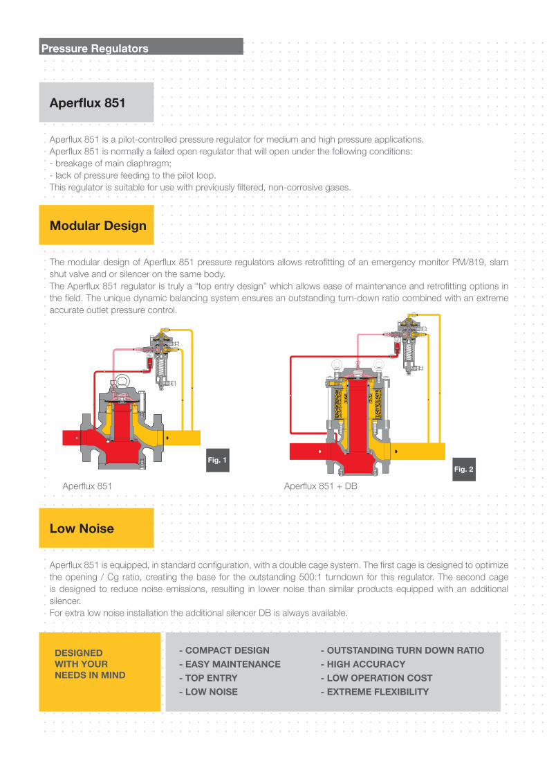
The Aperflux 851 pressure regulator offers the possibility of installing an incorporated slam shut valve SB/82 or HB/97 valve, depending on the regulator size. This can be done either during the manufacturing process or be retrofitted in the field. Retrofitting can be done without modifying the pressure regulator assembly.The Cg and KG coefficients of a regulator plus an incorporated slam-shut system are 5% lower than those for standard versions. The main characteristics of the slam shut are: - intervention for over pressure and/or under pressure - manual re-setting with internal bypass activated by the lever mechanism; - manual push button control;- compact dimensions; - easy maintenance; - optional pneumatic or electromagnetic remote control; - optional installation remote signal devices (contact switches or proximity switches).
Fig. 3 Fig. 4
INCORPORATED SLAM SHUT
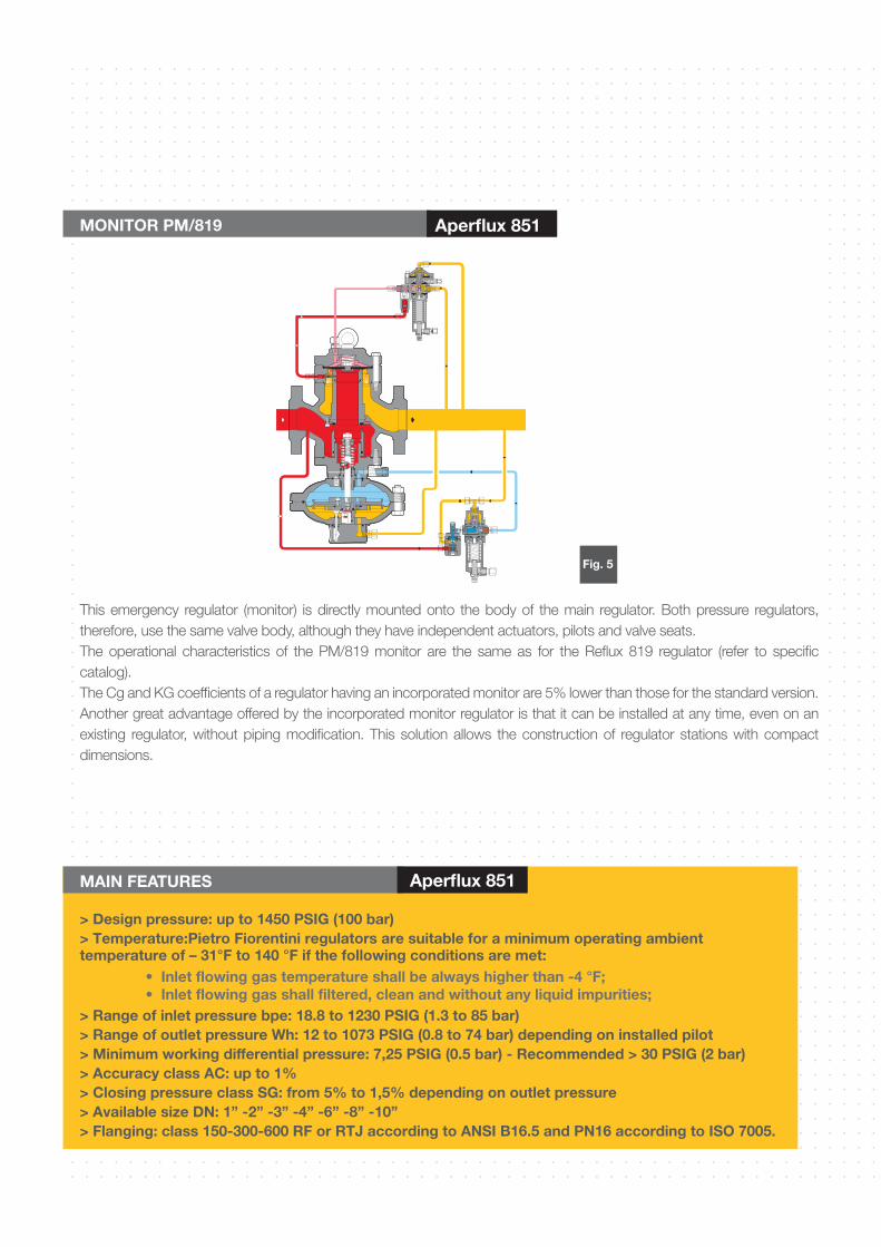
> Design pressure: up to 1450 PSIG (100 bar)> Temperature:Pietro Fiorentini regulators are suitable for a minimum operating ambient temperature of – 31°F to 140 °F if the following conditions are met:
> Range of inlet pressure bpe: 18.8 to 1230 PSIG (1.3 to 85 bar)> Range of outlet pressure Wh: 12 to 1073 PSIG (0.8 to 74 bar) depending on installed pilot > Minimum working differential pressure: 7,25 PSIG (0.5 bar) - Recommended > 30 PSIG (2 bar)> Accuracy class AC: up to 1%> Closing pressure class SG: from 5% to 1,5% depending on outlet pressure> Available size DN: 1” -2” -3” -4” -6” -8” -10”> Flanging: class 150-300-600 RF or RTJ according to ANSI b16.5 and PN16 according to ISO 7005.
MAIN FEATURES Aperflux 851
MONITOR PM/819 Aperflux 851
This emergency regulator (monitor) is directly mounted onto the body of the main regulator. Both pressure regulators, therefore, use the same valve body, although they have independent actuators, pilots and valve seats. The operational characteristics of the PM/819 monitor are the same as for the Reflux 819 regulator (refer to specific catalog). The Cg and KG coefficients of a regulator having an incorporated monitor are 5% lower than those for the standard version. Another great advantage offered by the incorporated monitor regulator is that it can be installed at any time, even on an existing regulator, without piping modification. This solution allows the construction of regulator stations with compact dimensions.
Fig. 5
• Inlet flowing gas temperature shall be always higher than -4 °F;• Inlet flowing gas shall filtered, clean and without any liquid impurities;
body Cast steel ASTM A352 LCC for classes 300 and 600ASTM A216 WCB for classes 150 and PN16
Head covers Rolled or forged carbon steel
Diaphgram Vulcanized rubber
Valve seat Stainless steel for DN ≤3”Carbon Steel with seal edge in stainless steel for size ≥ 4”
Seals Nitril rubber
Compression fittings According to DIN 2353 in zinc-plated carbon steel
The characteristics listed above are referred to as standard products. Special characteristics and materials for specific applications may be supplied upon request.
MATERIALS Aperflux 851
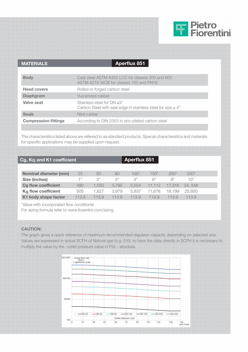
Cg, KG and K1 coefficient Aperflux 851
Nominal diameter (mm)Size (inches)Cg flow coefficientKG flow coefficientK1 body shape factor
251”
480505
113.9
502”
1,5501,627113.9
803”
3,7903,979113.9
100*4”
5,5545,837113.9
150*6”
11,11211,678113.9
200*8”
17,31618,199113.9
250*10”
24, 54825,850113.9
*Value with incorporated flow conditioner For sizing formula refer to www.fiorentini.com/sizing
CAUTION:The graph gives a quick reference of maximum recommended regulator capacity depending on selected size. Values are expressed in actual SCFH of Natural gas (s.g. 0,6): to have the data directly in SCFH it is necessary to multiply the value by the outlet pressure value in PSI – absolute.
100
35300
353150
3531500
DN 25 DN 50 DN 80 DN 100 DN 150 DN 200 DN 250
Outlet pressure ( psi)
Actual flow rate( ft3/h )
Logarithmic scale
and more0 14 29 43 58 72 87 101 116 130 145
PILOTS Aperflux 851
Aperflux 851 regulators are equipped with series 300 pilot as listed below:- 302/. control range Wh: 0.8 to 9,5 bar; (11 to 138 PSIG)- 304/. control range Wh: 7 to 43 bar; (100 to 625 PSIG)- 305/. control range Wh: 20 to 60 bar; (290 to 870 PSIG)- 307/. control range Wh: 41 to 74 bar; ( 595 to 1073 PSIG)Pilots may be adjusted manually or remotely as shown in table 3:
Table 3: Pilot adjusting instructions Aperflux 851
Pilot type .../A Manual settingPilot type .../D Electric remote setting controlPilot type .../CS Setting increased by pneumatic signal remote point
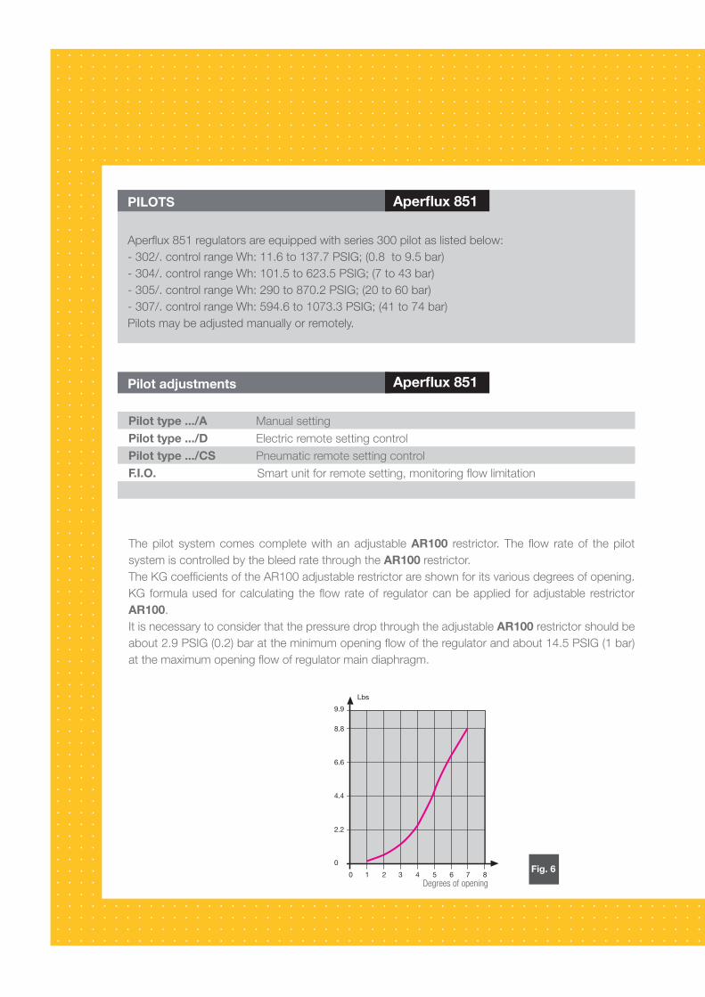
The pilot system comes complete with an adjustable AR100 restrictor. The flow rate of the pilot system is controlled by the bleed rate through AR100 restrictor.The KG coefficients of the AR100 adjustable restrictor for its various degrees of opening are shown on Fig. 2. KG formula used for calculating the flow rate of regulator can be applied for adjustable restrictor AR100.It is necessary to consider that pressure drop through the adjustable AR100 restrictor should be about 2.9 PSIG (0,2) bar at the minimum opening flow of the regulator and about 14,5 PSIG (1 bar) at the maximum opening flow of regulator main diaphragm.
ACCESSORIES ON REQUEST Aperflux 851
For Regulator- stroke limiter- flow-limiting devices- limit switches- position transmitters- stainless steel fittings, single or dual sealing
For Pilot- supplementary filter CF 14- dehydrating filter CF 14/D
Degrees of opening
PILOTS Aperflux 851
Aperflux 851 regulators are equipped with series 300 pilot as listed below:- 302/. control range Wh: 11.6 to 137.7 PSIG; (0.8 to 9.5 bar) - 304/. control range Wh: 101.5 to 623.5 PSIG; (7 to 43 bar)- 305/. control range Wh: 290 to 870.2 PSIG; (20 to 60 bar)- 307/. control range Wh: 594.6 to 1073.3 PSIG; (41 to 74 bar)Pilots may be adjusted manually or remotely.
Pilot adjustments Aperflux 851
The pilot system comes complete with an adjustable AR100 restrictor. The flow rate of the pilot system is controlled by the bleed rate through the AR100 restrictor.The KG coefficients of the AR100 adjustable restrictor are shown for its various degrees of opening.KG formula used for calculating the flow rate of regulator can be applied for adjustable restrictor AR100.It is necessary to consider that the pressure drop through the adjustable AR100 restrictor should be about 2.9 PSIG (0.2) bar at the minimum opening flow of the regulator and about 14.5 PSIG (1 bar) at the maximum opening flow of regulator main diaphragm.
Degrees of opening
Fig. 6
Pilot type .../A Manual settingPilot type .../D Electric remote setting controlPilot type .../CS Pneumatic remote setting control F.I.O. Smart unit for remote setting, monitoring flow limitation
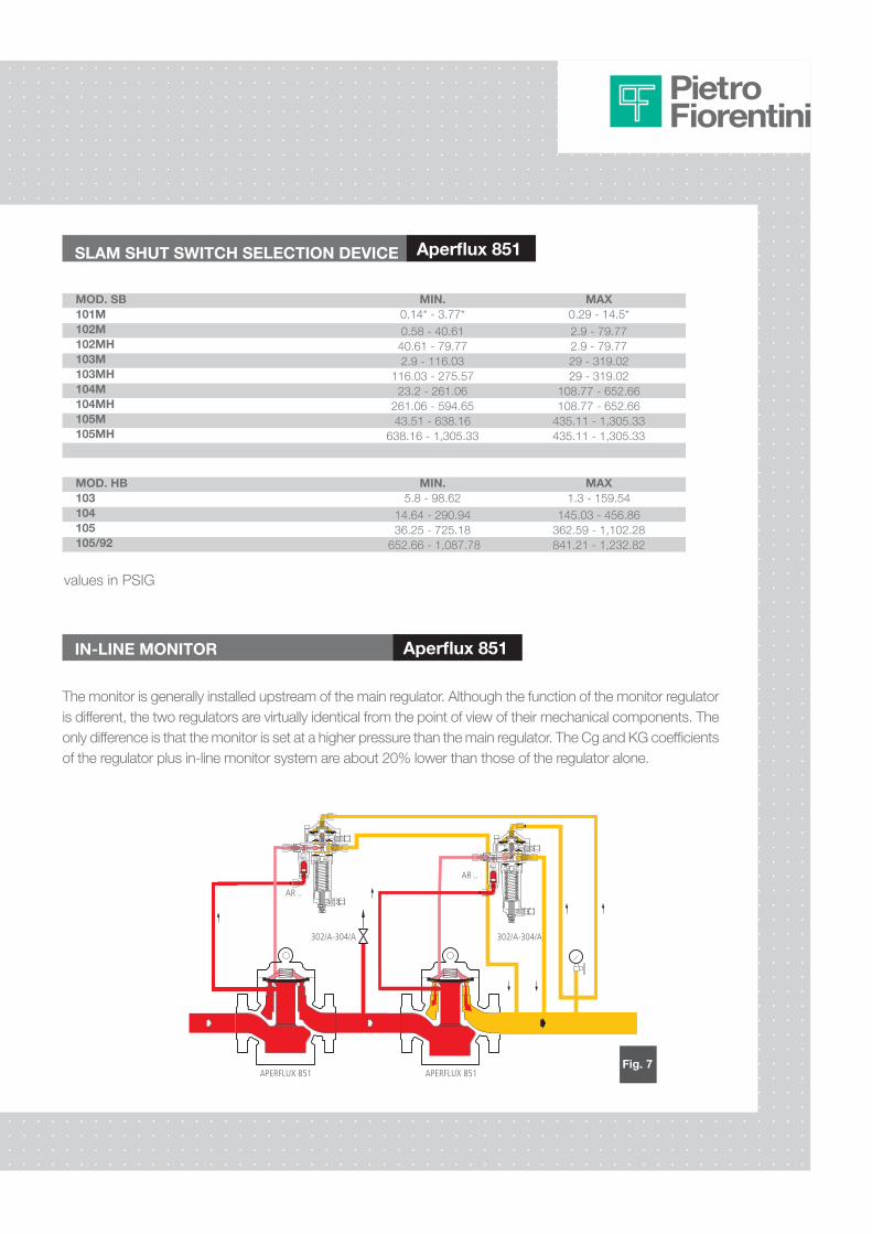
IN-LINE MONITOR Aperflux 851
The monitor is generally installed upstream of the main regulator. Although the function of the monitor regulator is different, the two regulators are virtually identical from the point of view of their mechanical components. The only difference is that the monitor is set at a higher pressure than the main regulator. The Cg and KG coefficients of the regulator plus in-line monitor system are about 20% lower than those of the regulator alone.
AR ..
AR ..
APERFLUX 851APERFLUX 851
302/A-304/A 302/A-304/A
MOD. Sb MIN. MAx101M 0.14* - 3.77* 0.29 - 14.5* 102M 0.58 - 40.61 2.9 - 79.77102MH 40.61 - 79.77 2.9 - 79.77103M 2.9 - 116.03 29 - 319.02103MH 116.03 - 275.57 29 - 319.02104M 23.2 - 261.06 108.77 - 652.66104MH 261.06 - 594.65 108.77 - 652.66105M 43.51 - 638.16 435.11 - 1,305.33105MH 638.16 - 1,305.33 435.11 - 1,305.33
SLAM SHUT SWITCH SELECTION DEVICE Aperflux 851
MOD. Hb MIN. MAx103 5.8 - 98.62 1.3 - 159.54104 14.64 - 290.94 145.03 - 456.86105 36.25 - 725.18 362.59 - 1,102.28105/92 652.66 - 1,087.78 841.21 - 1,232.82
values in PSIG
Fig. 7
EØ
DN DN
B
D
S
H
A
F
E
G
C
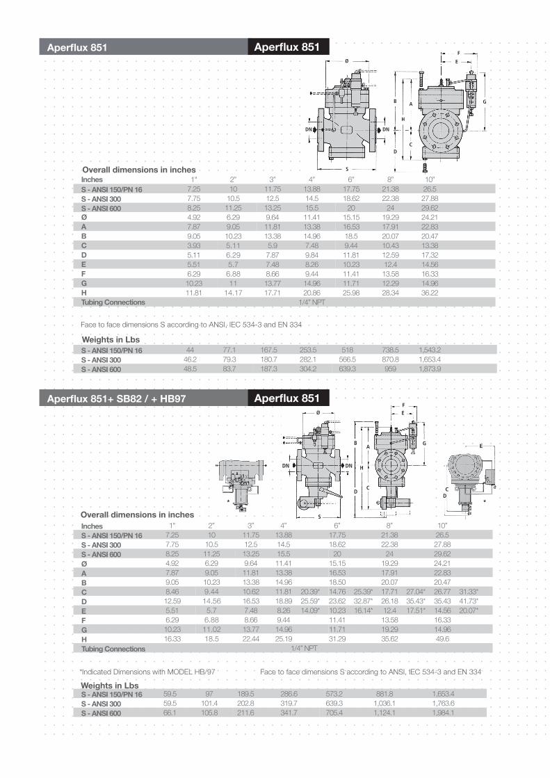
Inches 1" 2” 3” 4” 6” 8” 10”S - ANSI 150/PN 16 7.25 10 11.75 13.88 17.75 21.38 26.5S - ANSI 300 7.75 10.5 12.5 14.5 18.62 22.38 27.88S - ANSI 600 8.25 11.25 13.25 15.5 20 24 29.62Ø 4.92 6.29 9.64 11.41 15.15 19.29 24.21A 7.87 9.05 11.81 13.38 16.53 17.91 22.83b 9.05 10.23 13.38 14.96 18.50 20.07 20.47C 8.46 9.44 10.62 11.81 20.39* 14.76 25.39* 17.71 27.04* 26.77 31.33*D 12.59 14.56 16.53 18.89 25.59* 23.62 32.87* 26.18 35.43* 35.43 41.73*E 5.51 5.7 7.48 8.26 14.09* 10.23 16.14* 12.4 17.51* 14.56 20.07*F 6.29 6.88 8.66 9.44 11.41 13.58 16.33G 10.23 11.02 13.77 14.96 11.71 19.29 14.96H 16.33 18.5 22.44 25.19 31.29 35.62 49.6Tubing Connections 1/4” NPT
*Indicated Dimensions with MODEL HB/97 Face to face dimensions S according to ANSI, IEC 534-3 and EN 334
Overall dimensions in inches
S - ANSI 150/PN 16 59.5 97 189.5 286.6 573.2 881.8 1,653.4S - ANSI 300 59.5 101.4 202.8 319.7 639.3 1,036.1 1,763.6S - ANSI 600 66.1 105.8 211.6 341.7 705.4 1,124.1 1,984.1
Weights in Lbs
Inches 1" 2” 3” 4” 6” 8” 10”S - ANSI 150/PN 16 7.25 10 11.75 13.88 17.75 21.38 26.5S - ANSI 300 7.75 10.5 12.5 14.5 18.62 22.38 27.88S - ANSI 600 8.25 11.25 13.25 15.5 20 24 29.62Ø 4.92 6.29 9.64 11.41 15.15 19.29 24.21A 7.87 9.05 11.81 13.38 16.53 17.91 22.83b 9.05 10.23 13.38 14.96 18.5 20.07 20.47C 3.93 5.11 5.9 7.48 9.44 10.43 13.38D 5.11 6.29 7.87 9.84 11.81 12.59 17.32E 5.51 5.7 7.48 8.26 10.23 12.4 14.56F 6.29 6.88 8.66 9.44 11.41 13.58 16.33G 10.23 11 13.77 14.96 11.71 12.29 14.96H 11.81 14.17 17.71 20.86 25.98 28.34 36.22Tubing Connections 1/4” NPT
Face to face dimensions S according to ANSI, IEC 534-3 and EN 334
Overall dimensions in inches
S - ANSI 150/PN 16 44 77.1 167.5 253.5 518 738.5 1,543.2S - ANSI 300 46.2 79.3 180.7 282.1 566.5 870.8 1,653.4S - ANSI 600 48.5 83.7 187.3 304.2 639.3 959 1,873.9
Weights in Lbs
*
E
CD
*
Ø
DN DN
S
D
BA
C
FE
G
H
Aperflux 851 Aperflux 851
Aperflux 851+ Sb82 / + Hb97 Aperflux 851
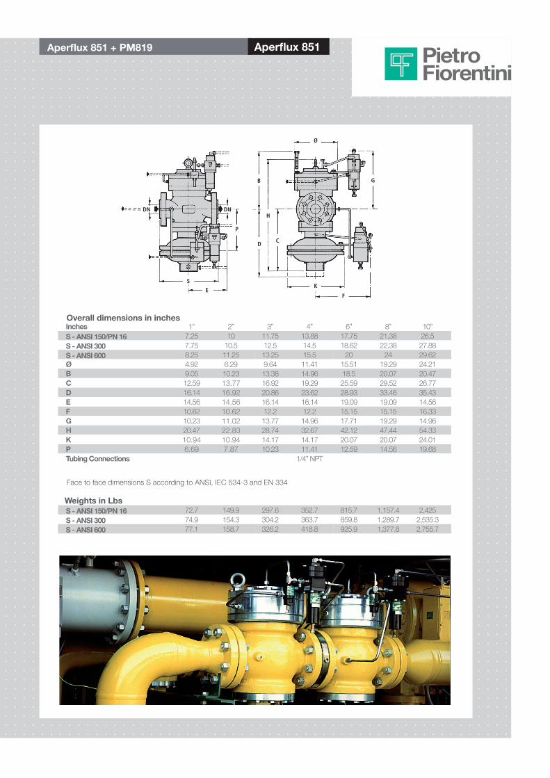
Aperflux 851 + PM819 Aperflux 851
Inches 1" 2” 3” 4” 6” 8” 10”S - ANSI 150/PN 16 7.25 10 11.75 13.88 17.75 21.38 26.5S - ANSI 300 7.75 10.5 12.5 14.5 18.62 22.38 27.88S - ANSI 600 8.25 11.25 13.25 15.5 20 24 29.62Ø 4.92 6.29 9.64 11.41 15.51 19.29 24.21b 9.05 10.23 13.38 14.96 18.5 20.07 20.47C 12.59 13.77 16.92 19.29 25.59 29.52 26.77D 16.14 16.92 20.86 23.62 28.93 33.46 35.43E 14.56 14.56 16.14 16.14 19.09 19.09 14.56F 10.62 10.62 12.2 12.2 15.15 15.15 16.33G 10.23 11.02 13.77 14.96 17.71 19.29 14.96H 20.47 22.83 28.74 32.67 42.12 47.44 54.33K 10.94 10.94 14.17 14.17 20.07 20.07 24.01P 6.69 7.87 10.23 11.41 12.59 14.56 19.68Tubing Connections 1/4” NPT
Face to face dimensions S according to ANSI, IEC 534-3 and EN 334
Overall dimensions in inches
S - ANSI 150/PN 16 72.7 149.9 297.6 352.7 815.7 1,157.4 2,425S - ANSI 300 74.9 154.3 304.2 363.7 859.8 1,289.7 2,535.3S - ANSI 600 77.1 158.7 326.2 418.8 925.9 1,377.8 2,755.7
Weights in Lbs
DN DN
S
E
B
D
H
C
K
F
G
Ø
P
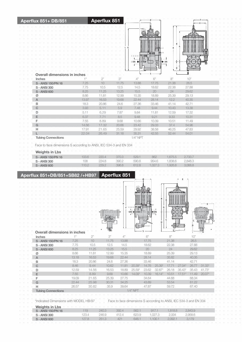
Inches 1" 2” 3” 4” 6” 8” 10”S - ANSI 150/PN 16 7.25 10 11.75 13.88 17.75 21.38 26.5S - ANSI 300 7.75 10.5 12.5 14.5 18.62 22.38 27.88S - ANSI 600 8.25 11.25 13.25 15.5 20 24 29.62Ø 8.66 11.81 12.99 15.35 18.89 25.39 29.13A 13.97 16.53 19.68 22.44 28.14 12.2 40.35b 18.3 20.86 24.6 27.36 33.46 41.14 42.71C 3.93 5.11 5.9 7.48 9.44 10.43 13.38D 5.11 6.29 7.87 9.84 11.81 12.59 17.32E 6.37 7.71 8.5 9.48 9.21 9.33 10.31F 7.55 8.89 9.68 10.66 10.39 10.51 11.49G 14.56 17.32 20.66 23.42 29.33 37.4 54.96H 17.91 21.65 25.59 29.92 38.58 46.25 47.83L 22.04 26.49 31.18 35.31 42.55 52.44 54.01Tubing Connections 1/4” NPT
Face to face dimensions S according to ANSI, IEC 534-3 and EN 334
Overall dimensions in inches
S - ANSI 150/PN 16 103.6 220.4 370.3 529.1 862 1,675.5 2,733.7S - ANSI 300 108 224.8 390.2 590.8 954.6 1,838.6 2,848.3S - ANSI 600 110.2 229.2 396.8 612.8 1,027.3 1,926.8 3,068.8
Weights in Lbs
Aperflux 851+ Db/851 Aperflux 851
GL
DN DN
Ø F
E
AB
H
DC
S
Ø E
B A
G
CD
E
C
D
H
F
S
DN DN
* *
Aperflux 851+Db/851+Sb82 /+Hb97 Aperflux 851
Inches 1" 2” 3” 4” 6” 8” 10”S - ANSI 150/PN 16 7.25 10 11.75 13.88 17.75 21.38 26.5S - ANSI 300 7.75 10.5 12.5 14.5 18.62 22.38 27.88S - ANSI 600 8.25 11.25 13.25 15.5 20 24 29.62Ø 8.66 11.81 12.99 15.35 18.89 25.39 29.13A 13.18 16.53 19.68 22.44 28.14 35.82 40.35b 18.3 20.86 24.6 27.36 33.46 41.14 42.71C 8.46 9.44 10.62 11.81 20.39* 14.76 25.39* 17.71 27.04* 26.77 31.33*D 12.59 14.56 16.53 18.89 25.59* 23.62 32.87* 26.18 35.43* 35.43 41.73*E 7.55 8.89 9.68 10.66 14.09* 10.39 16.14* 10.51 17.51* 11.49 20.07*F 19.09 21.65 25.39 27.75 34.64 44.68 68.34G 22.44 25.98 30.31 34.25 43.89 53.54 61.22H 26.57 30.82 35.9 39.64 47.87 59.72 67.40Tubing Connections 1/4” NPT
*Indicated Dimensions with MODEL HB/97 Face to face dimensions S according to ANSI, IEC 534-3 and EN 334
Overall dimensions in inches
S - ANSI 150/PN 16 119 240.3 392.4 562.1 917.1 1,818.8 2,843.9S - ANSI 300 123.4 246.9 412.4 623.9 1,027.3 2,004 2,958.6S - ANSI 600 127.8 251.3 421 648.1 1,100.1 2,092.1 3,179
Weights in Lbs
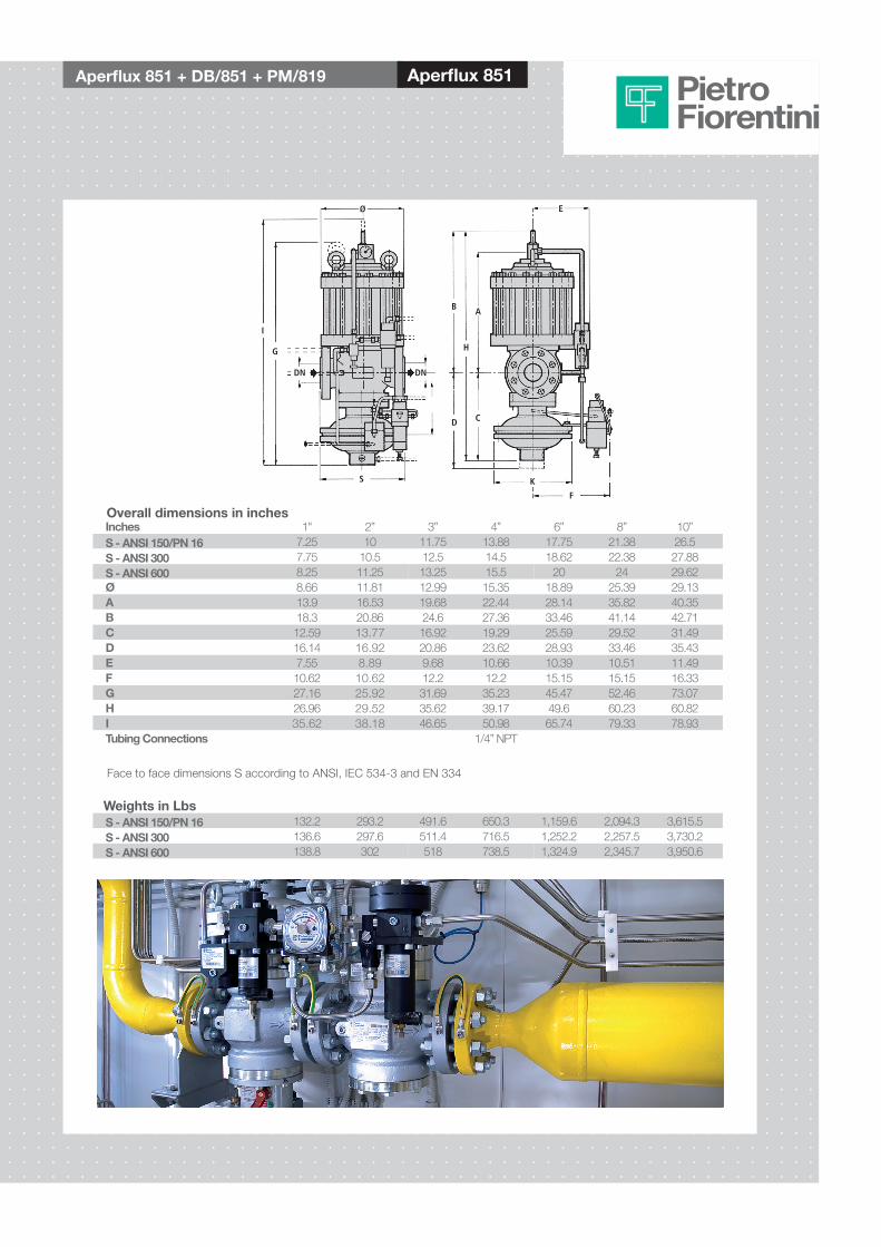
Aperflux 851 + Db/851 + PM/819 Aperflux 851
G
I
DN DN
Ø
F
E
AB
H
D C
KS
Inches 1" 2” 3” 4” 6” 8” 10”S - ANSI 150/PN 16 7.25 10 11.75 13.88 17.75 21.38 26.5S - ANSI 300 7.75 10.5 12.5 14.5 18.62 22.38 27.88S - ANSI 600 8.25 11.25 13.25 15.5 20 24 29.62Ø 8.66 11.81 12.99 15.35 18.89 25.39 29.13A 13.9 16.53 19.68 22.44 28.14 35.82 40.35b 18.3 20.86 24.6 27.36 33.46 41.14 42.71C 12.59 13.77 16.92 19.29 25.59 29.52 31.49D 16.14 16.92 20.86 23.62 28.93 33.46 35.43E 7.55 8.89 9.68 10.66 10.39 10.51 11.49F 10.62 10.62 12.2 12.2 15.15 15.15 16.33G 27.16 25.92 31.69 35.23 45.47 52.46 73.07H 26.96 29.52 35.62 39.17 49.6 60.23 60.82I 35.62 38.18 46.65 50.98 65.74 79.33 78.93Tubing Connections 1/4” NPT
Face to face dimensions S according to ANSI, IEC 534-3 and EN 334
Overall dimensions in inches
S - ANSI 150/PN 16 132.2 293.2 491.6 650.3 1,159.6 2,094.3 3,615.5S - ANSI 300 136.6 297.6 511.4 716.5 1,252.2 2,257.5 3,730.2S - ANSI 600 138.8 302 518 738.5 1,324.9 2,345.7 3,950.6
Weights in Lbs

This data is not binding. We reserve the right to make changes without prior notice.
www.fiorentini.com
Reducing and MeteringStations
Ball ValvesSlam Shut Valves
Pietro Fiorentini Solutions
DA SISTEMARE !!!!!!!!
CT-AF851 April 2013
Pietro Fiorentini S.p.A.via E.Fermi 8/10I-36057 Arcugnano (VI) Italy
Tel: +39 0444 968.511Fax: +39 0444 960.468
Fiorentini USA4555 South Berkeley Lake RoadNorcross, GA 30071
Toll - Free: 888.618.8787Fax: 770.448.7312
www.fiousa.com