Embed Size (px)
Citation preview

Apeks XTX 2nd Stage Regulator

Please Turn Off The Cell Phones
4
Copyright NoticeThis program is copyrighted, all rights reserved. It may not
in whole or in part, be copied, photocopied, reproduced
translated, or reduced to any electronic medium or machine
readable form without prior consent in writing from Aqua Lung
International. It may not be distributed through the internet or
computer bulletin board systems without prior consent in
writing from Aqua Lung International
©2006 Aqua Lung International, Inc
Apeks XTX Service Program
Features• Pneumatically Balanced Valve Design
– Ratcheting, indexable venturi control
and user adjustment knob (200,100 & 50)
• Diver Changeable Exhaust (DCE)– Allows diver to change between a large tee for bubble dispersion
and a small tee for compactness
• Left/Right Hose Reversibility– Can be configured for left or right hand use
• Suitable For Coldwater Use– Can be used in water temps below <50F (Except XTX20)

Begin Disassembly
Click here for left-handed conversion
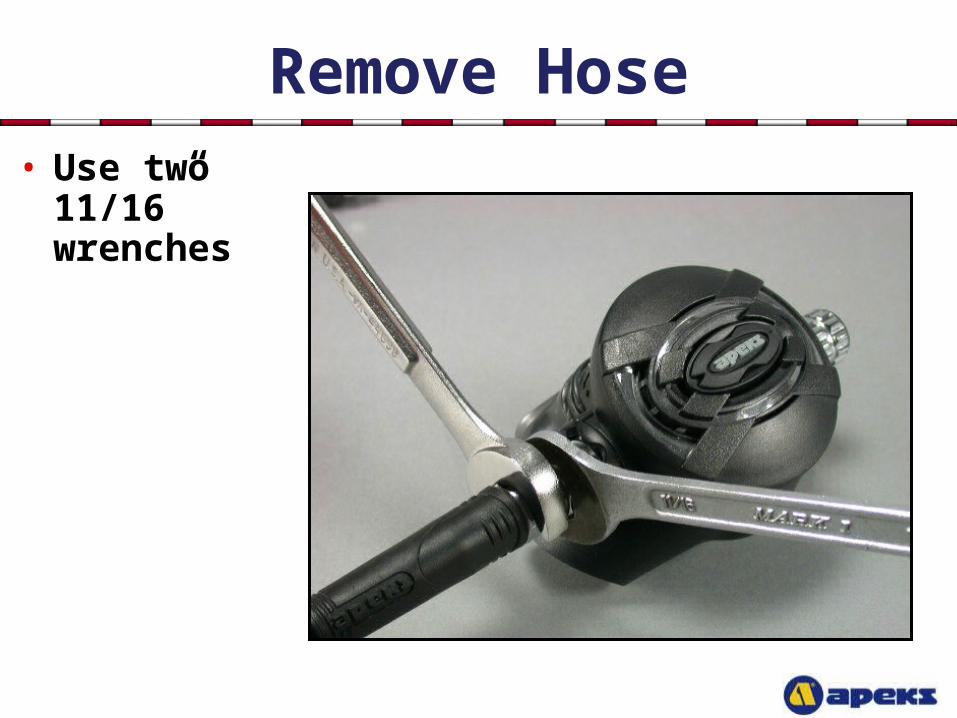
Remove Hose• Use two 11/16”
wrenches
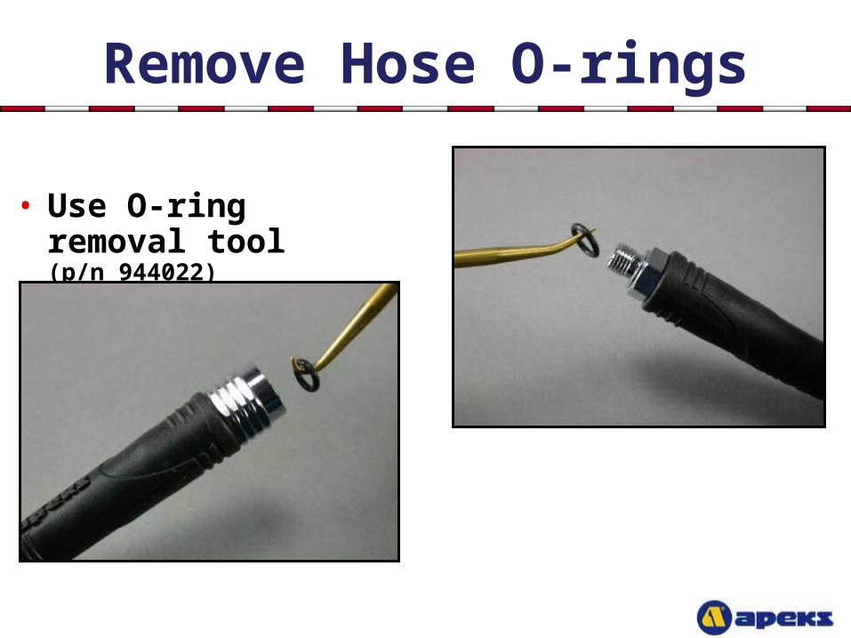
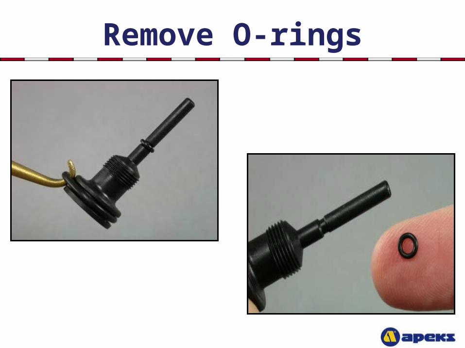
Remove Hose O-rings
• Use O-ring removal tool (p/n 944022)
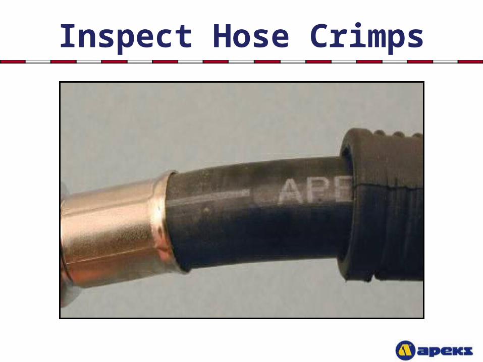
Inspect Hose Crimps
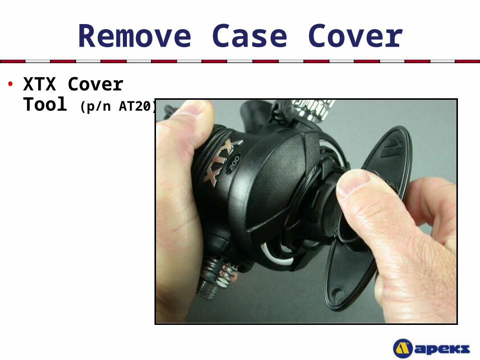
Remove Case Cover• XTX Cover Tool
(p/n AT20)
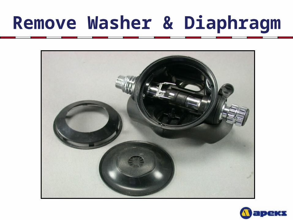
Remove Washer & Diaphragm
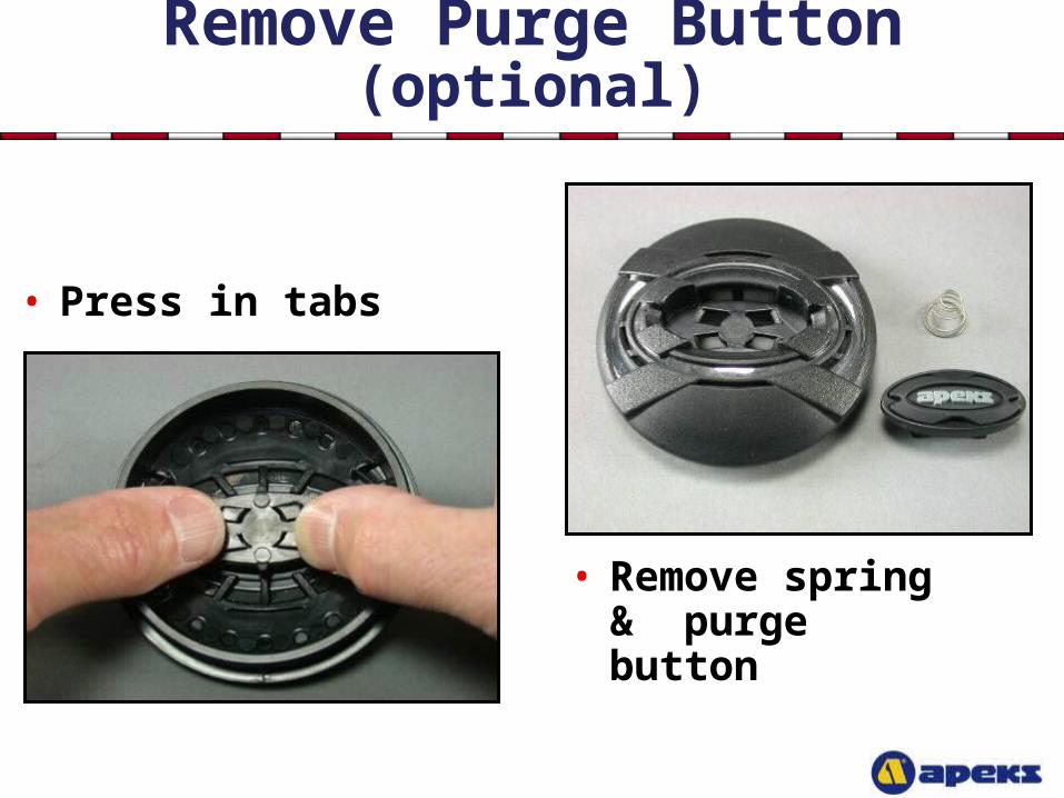
Remove Purge Button (optional)
• Remove spring & purge button
• Press in tabs
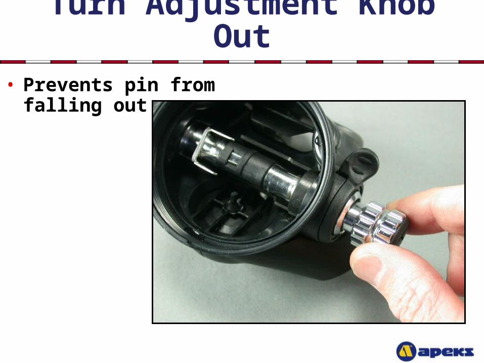
Turn Adjustment Knob Out• Prevents pin from
falling out
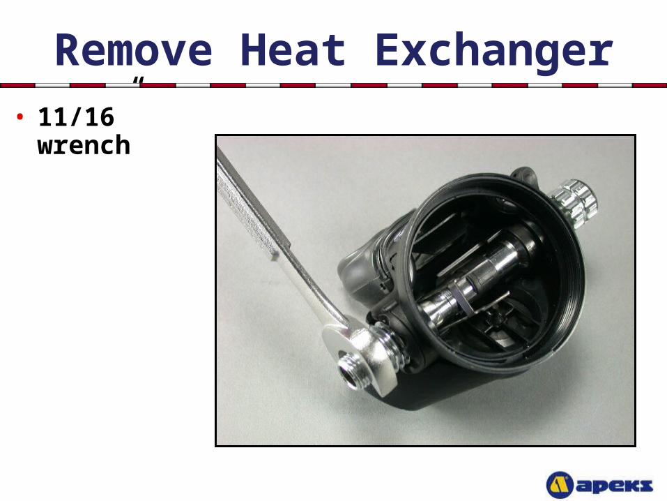
Remove Heat Exchanger• 11/16” wrench
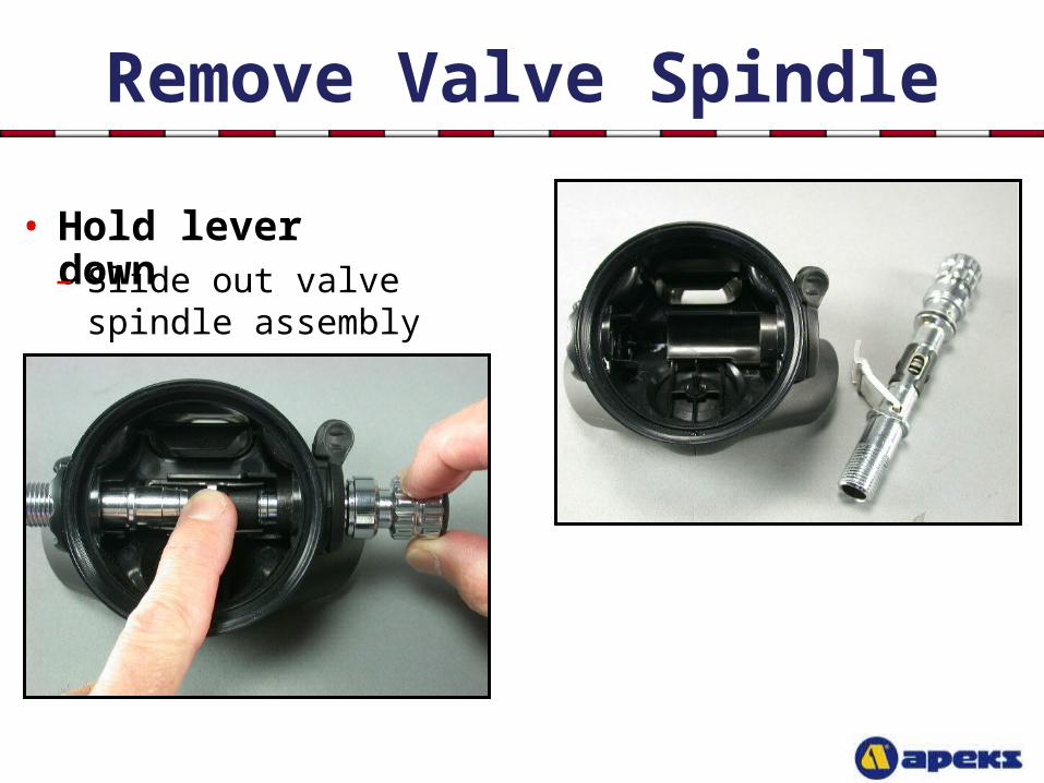
Remove Valve Spindle
• Hold lever down
– Slide out valve spindle assembly
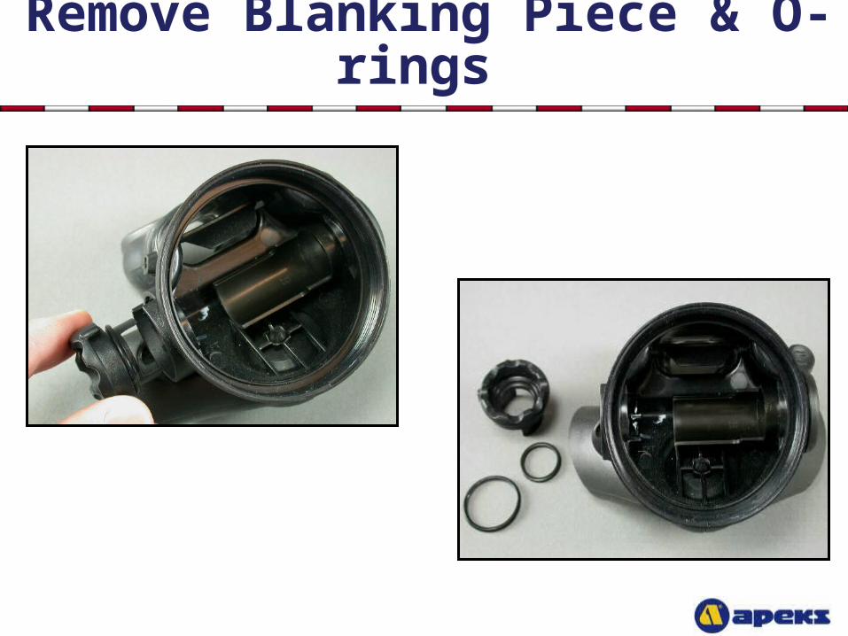
Remove Blanking Piece & O-rings
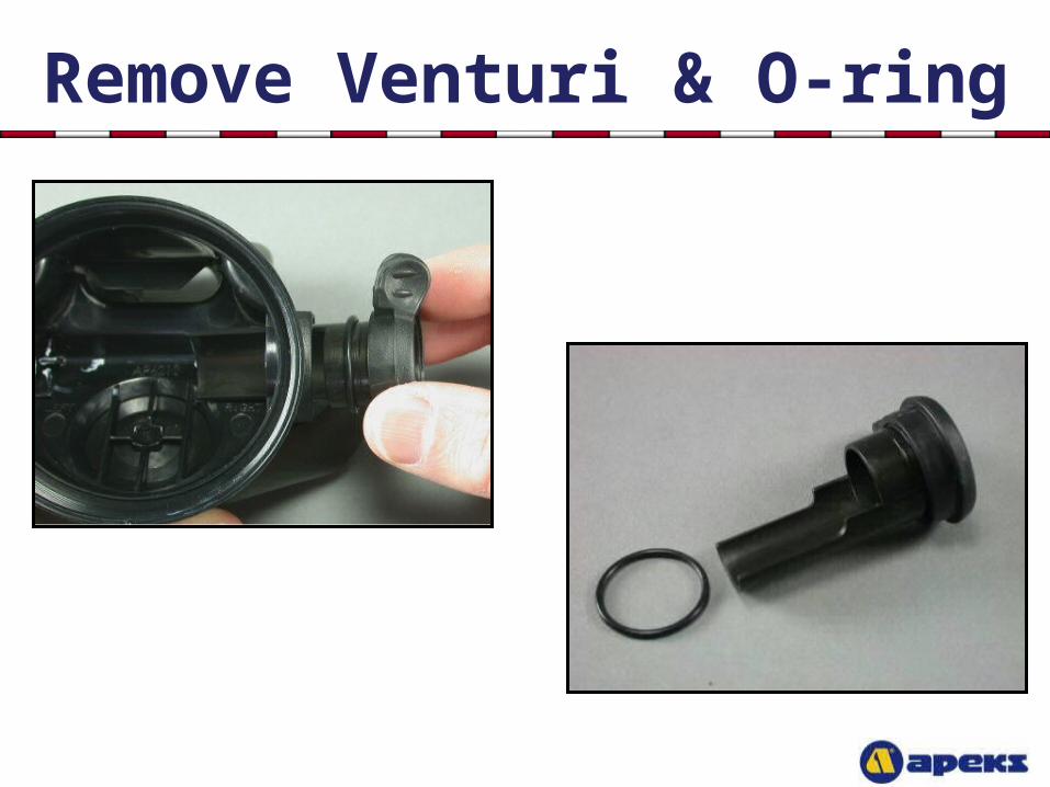
Remove Venturi & O-ring
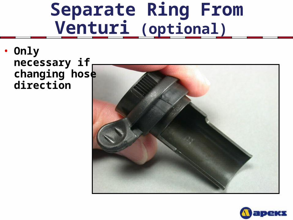
Separate Ring From Venturi (optional)
• Only necessary if changing hose direction
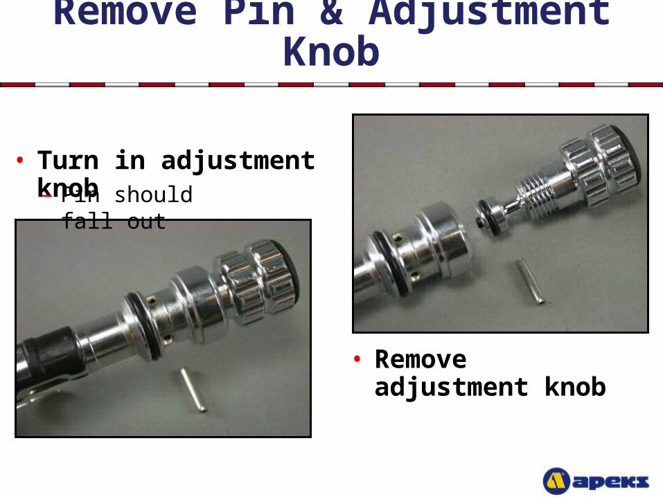
Remove Pin & Adjustment Knob
• Turn in adjustment knob – Pin should fall out
• Remove adjustment knob
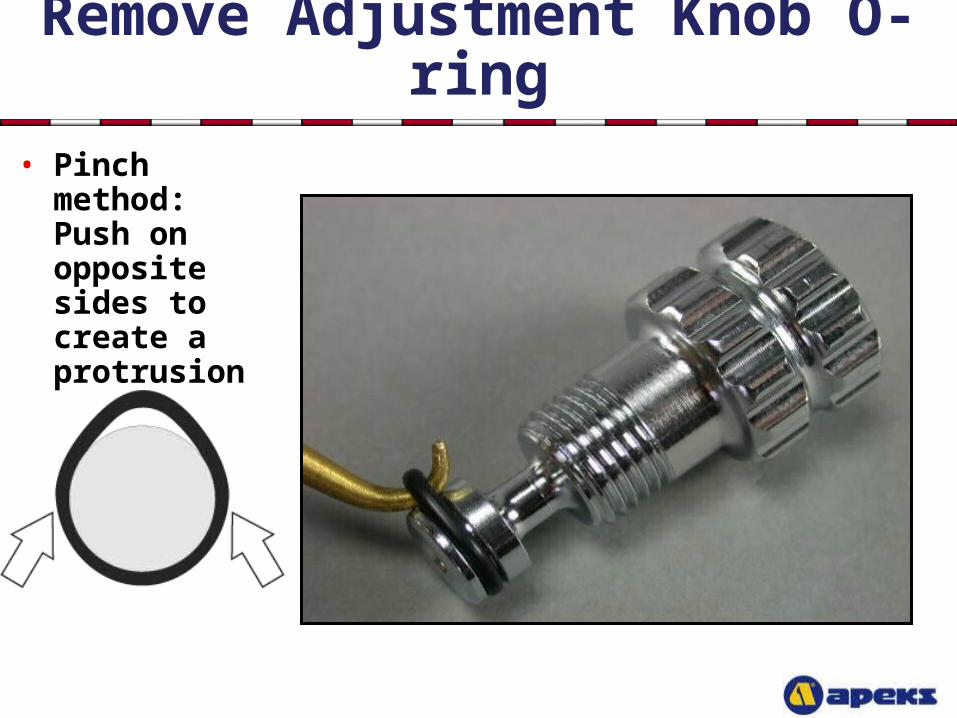
Remove Adjustment Knob O-ring• Pinch method:
Push on opposite sides to create a protrusion
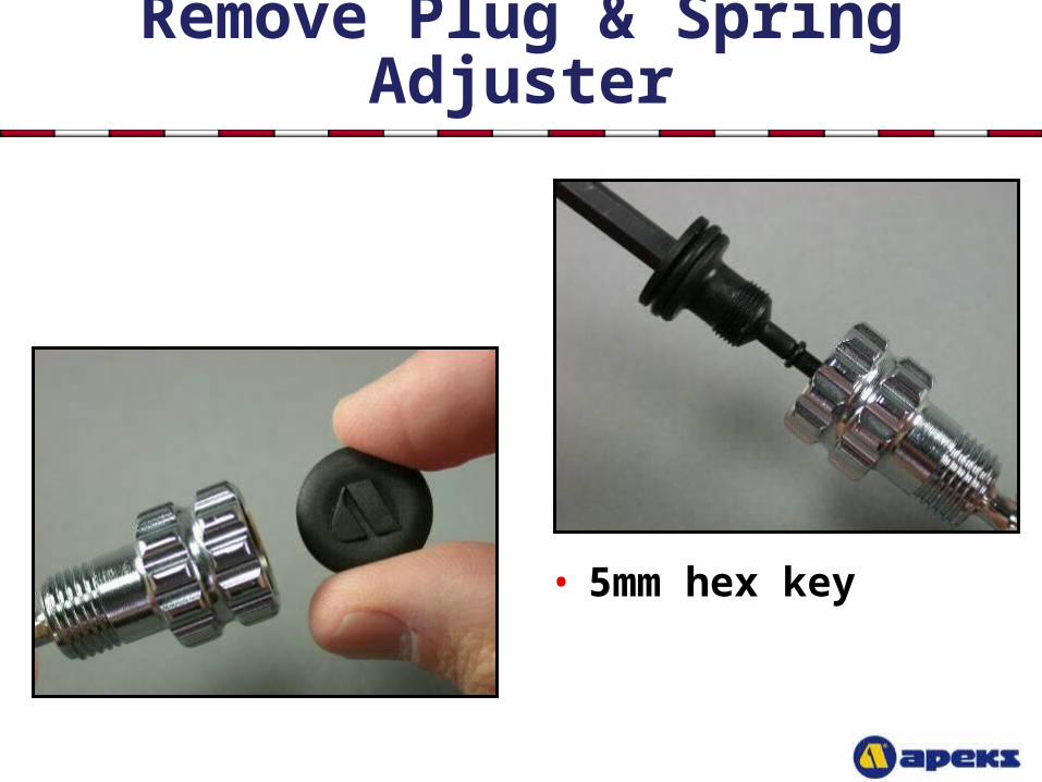
Remove Plug & Spring Adjuster
• 5mm hex key
Remove O-rings
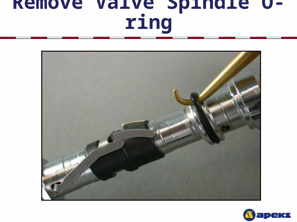
Remove Valve Spindle O-ring
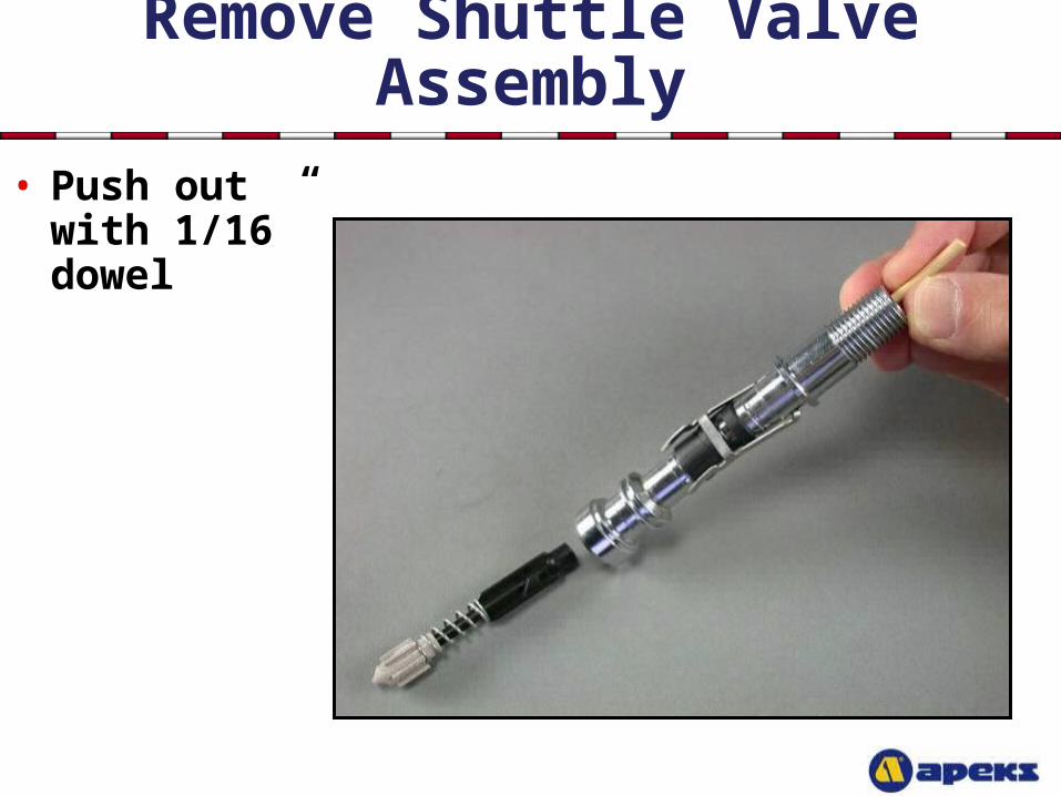
Remove Shuttle Valve Assembly
• Push out with 1/16” dowel
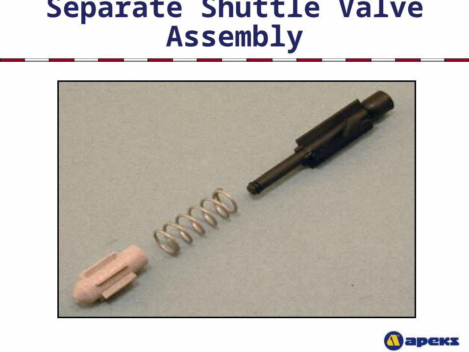
Separate Shuttle Valve Assembly
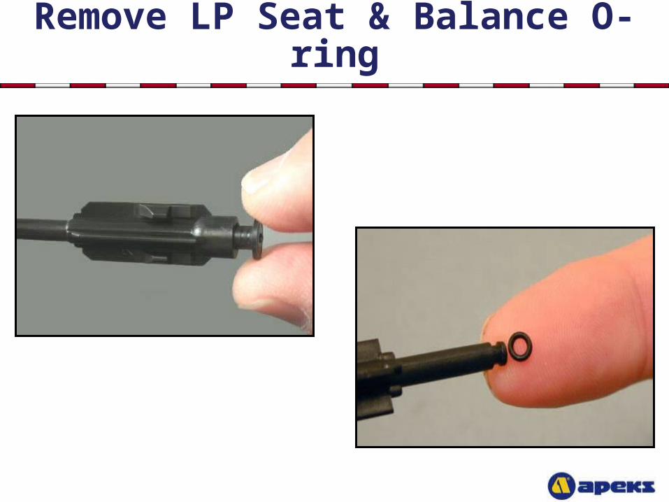
Remove LP Seat & Balance O-ring
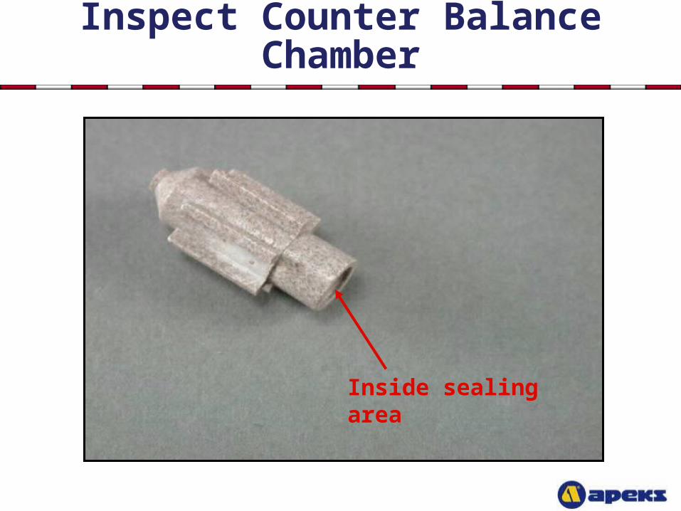
Inspect Counter Balance Chamber
Inside sealing area
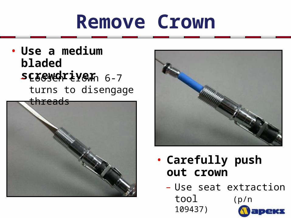
Remove Crown
• Carefully push out crown
• Use a medium bladed screwdriver– Loosen crown 6-7 turns to
disengage threads
– Use seat extraction tool (p/n 109437)
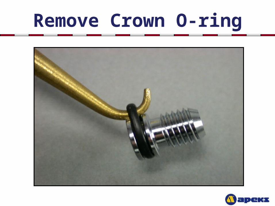
Remove Crown O-ring
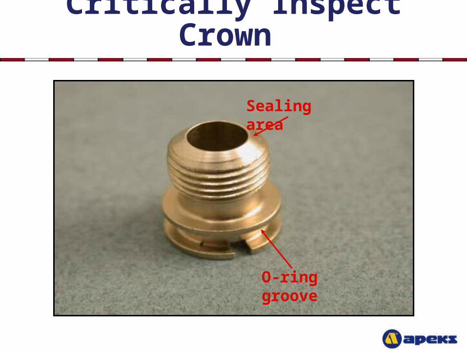
Critically Inspect Crown
Sealing area
O-ring groove
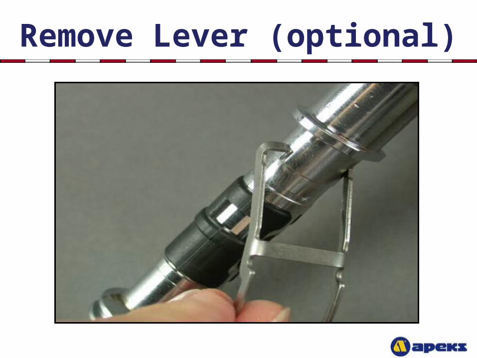
Remove Lever (optional)
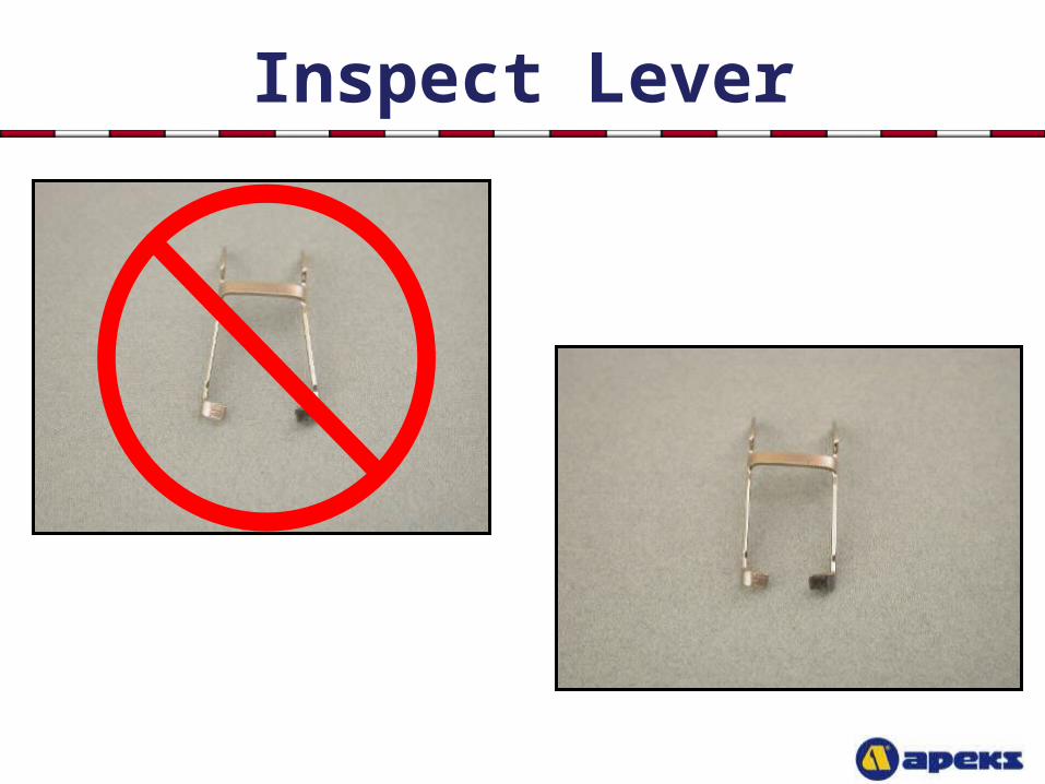
Inspect Lever
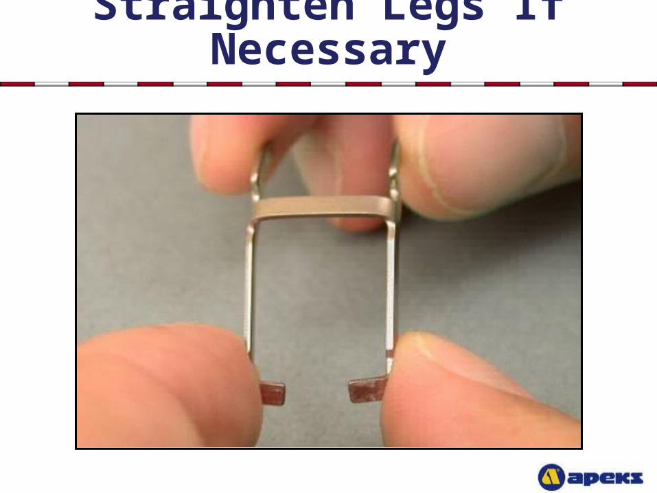
Straighten Legs If Necessary
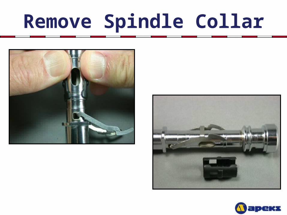
Remove Spindle Collar
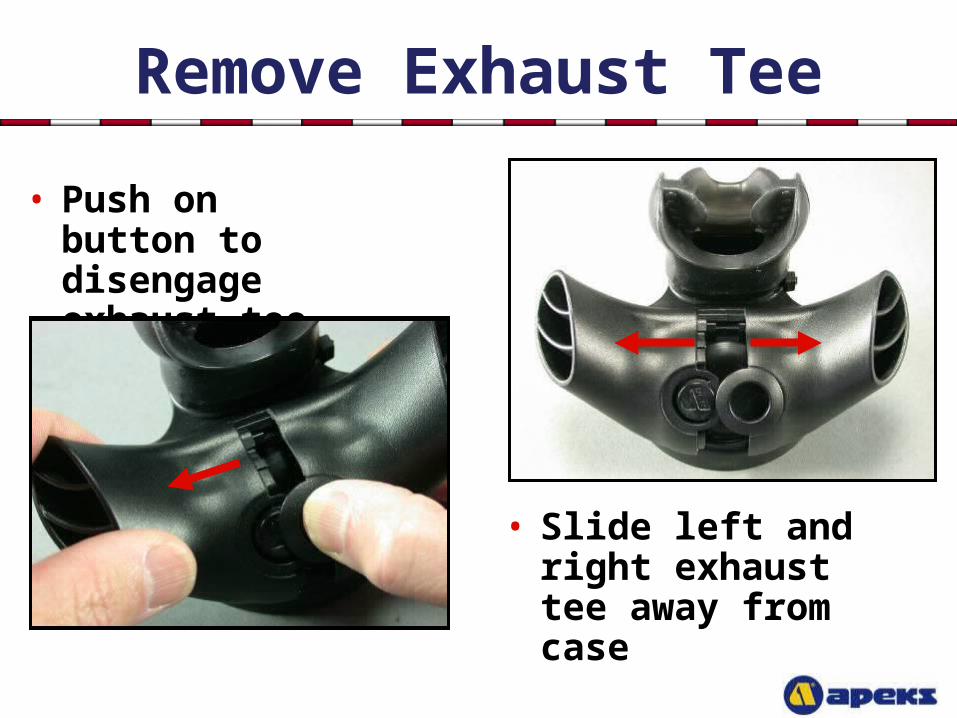
Remove Exhaust Tee
• Push on button to disengage exhaust tee
• Slide left and right exhaust tee away from case
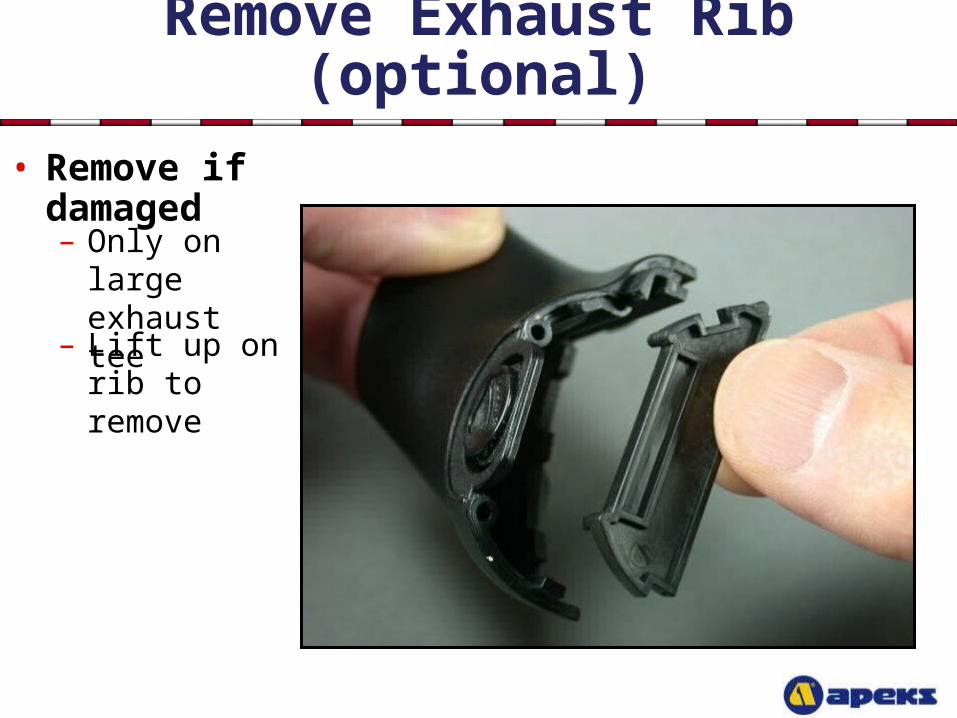
Remove Exhaust Rib (optional)
• Remove if damaged
– Lift up on rib to remove
– Only on large exhaust tee
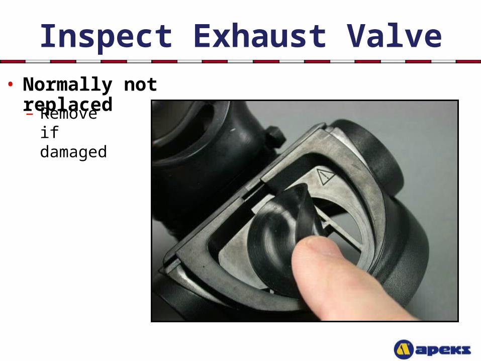
Inspect Exhaust Valve• Normally not replaced
– Remove if
damaged
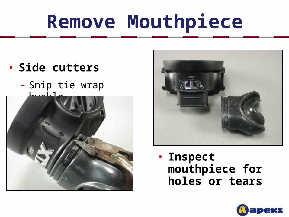
Remove Mouthpiece
• Side cutters
– Snip tie wrap buckle
• Inspect mouthpiece for holes or tears

Cleaning & Lubrication Procedures
Click here to skip past Cleaning & Lubrication Procedures and go straight to Reassembly
Cleaning & Lubrication
• Brass and Stainless Steel Parts
– Pre-clean in warm soapy water; nylon bristle brush
– Ultrasonically clean with soapy water; vinegar OK on tough corrosion
– Rinse in fresh water; use distilled water if tap water is “hard”
– Blow dry with LP hydrocarbon free gas (for EAN use)
Cleaning & Lubrication
• Aluminum, Plastic & Rubber Parts
– Soak in warm, soapy water
– Use soft nylon bristle brush to remove deposits
– Rinse with fresh water
– Blow dry with LP hydrocarbon free gas (for EAN use)
CAUTION: DO NOT soak plastic parts in acidic solutions !
Cleaning & Lubrication
• Hoses
– Soak hose ends only
– Do not allow solution to enter hose
– Rinse with fresh water
– Dry with hose ends hanging down
– Blow out hose before installing
Cleaning & Lubrication
• Lubrication
– Christo-lube MCG 111
– Light film only Rinse with fresh water
– Remove visible excess
– If regulator will be used with EAN, you should wear powderless, latex gloves (or equivalent) when lubricating and handling o-rings

Begin Reassembly
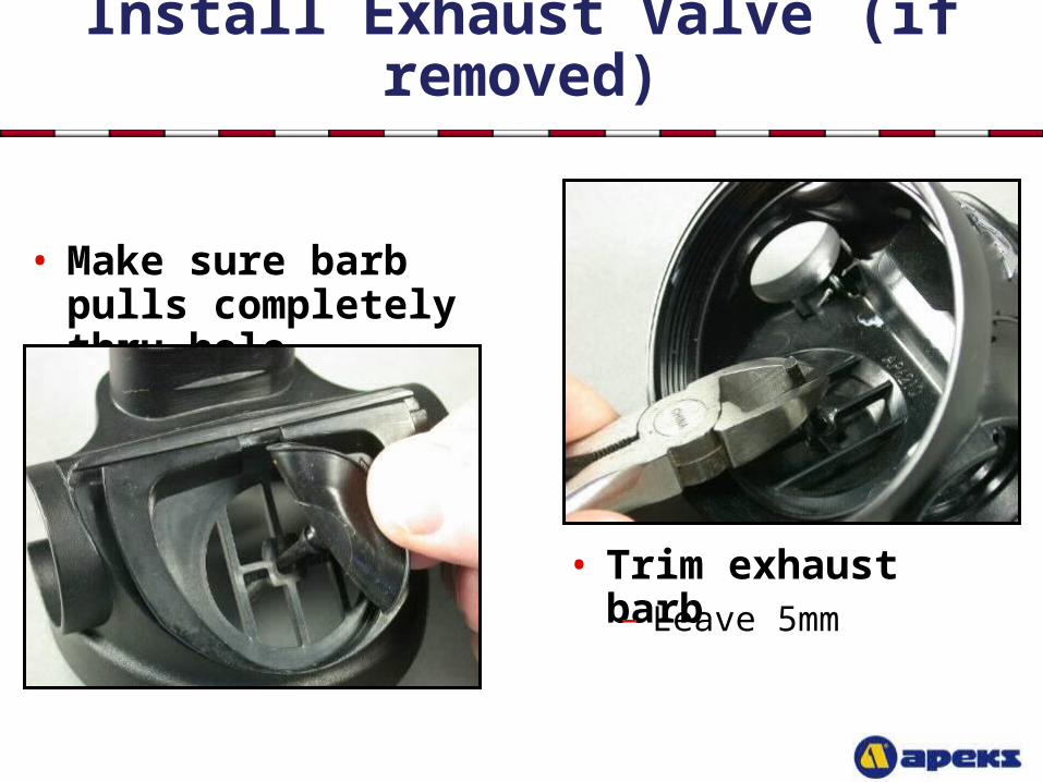
Install Exhaust Valve (if removed)
• Make sure barb pulls completely thru hole
• Trim exhaust barb
– Leave 5mm
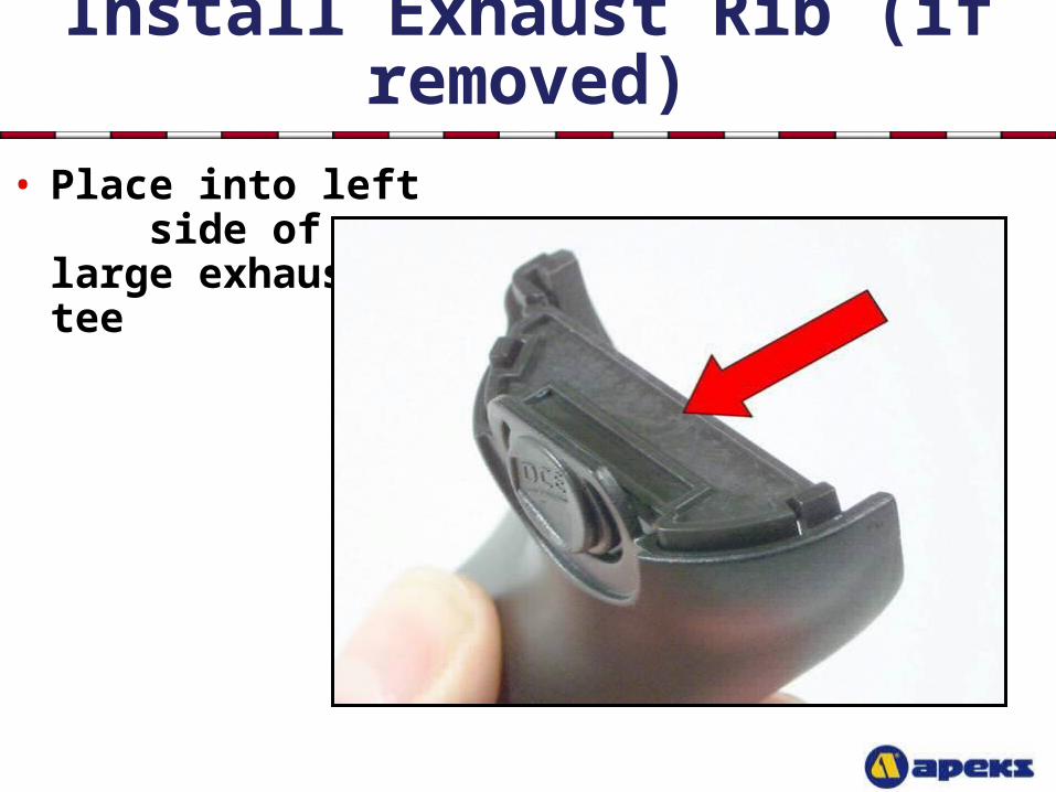
Install Exhaust Rib (if removed)• Place into left
side of large exhaust tee
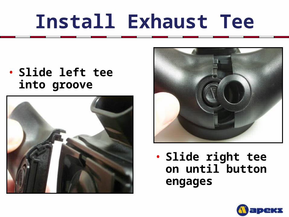
Install Exhaust Tee
• Slide left tee into groove
• Slide right tee on until button engages
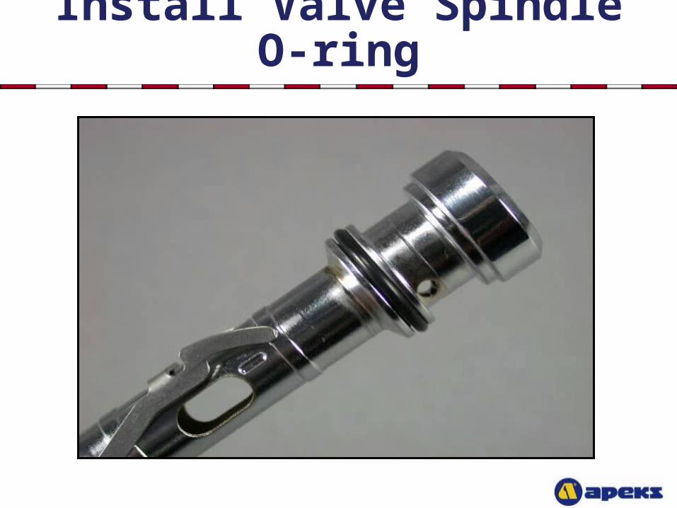
Install Valve Spindle O-ring
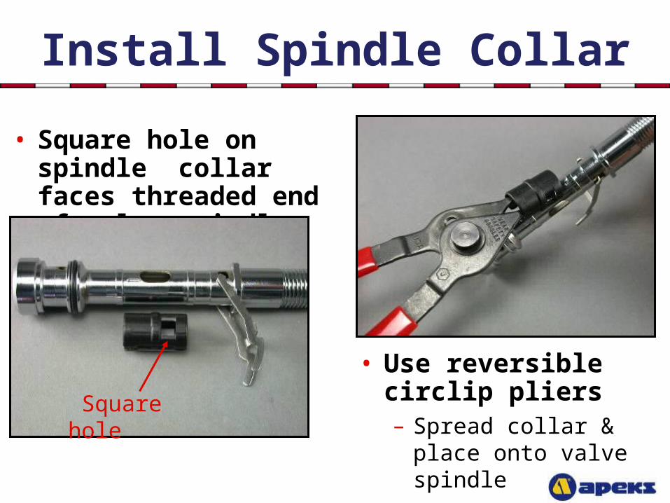
Install Spindle Collar
• Square hole on spindle collar faces threaded end of valve spindle
• Use reversible circlip pliers– Spread collar & place
onto valve spindle
Square hole
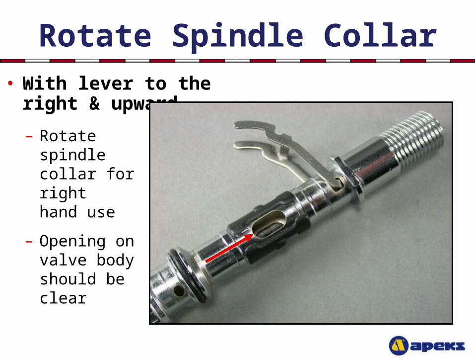
Rotate Spindle Collar• With lever to the right
& upward
– Rotate spindle collar for right hand use
– Opening on valve body should be clear
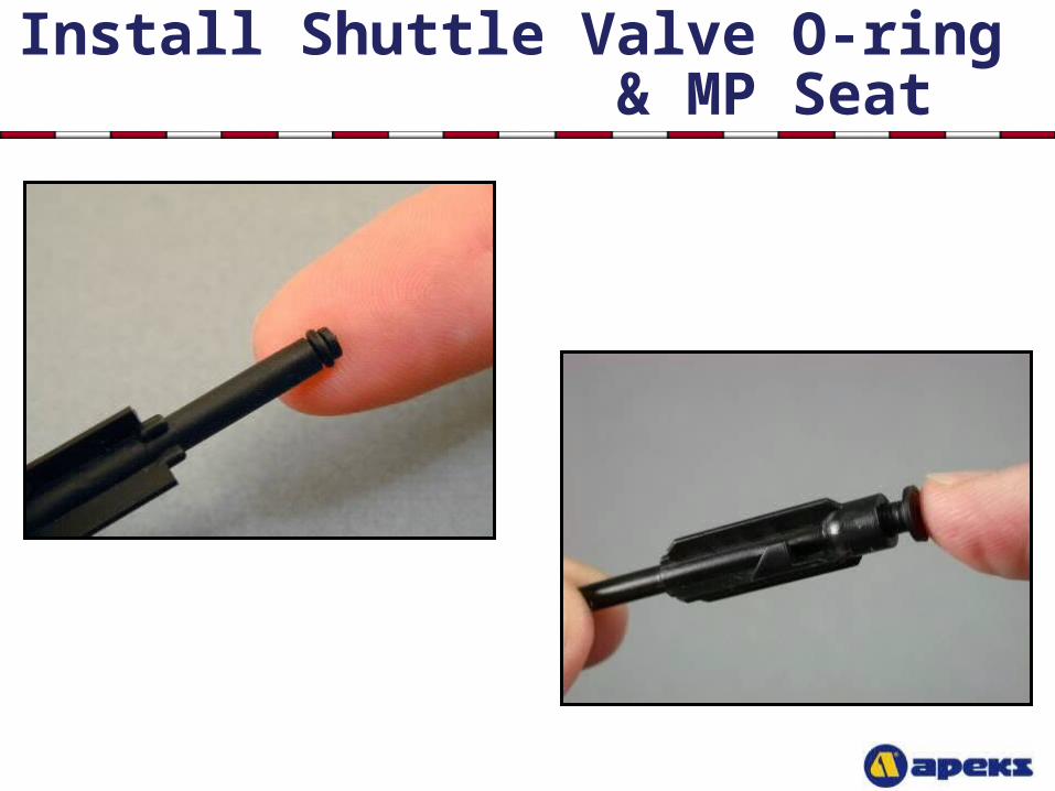
Install Shuttle Valve O-ring & MP Seat
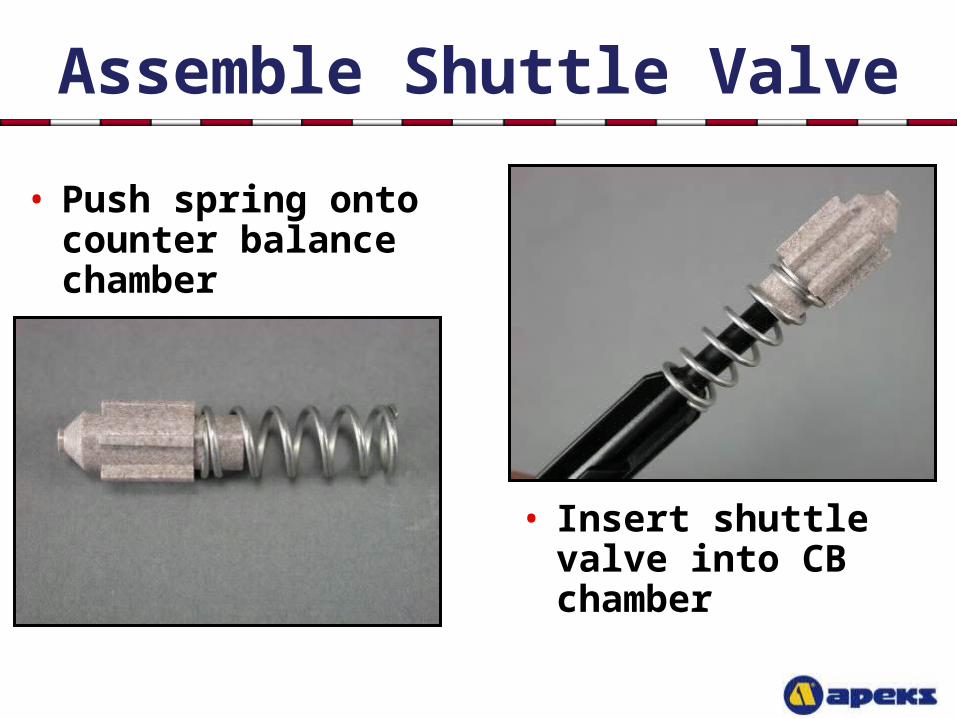
Assemble Shuttle Valve
• Push spring onto counter balance chamber
• Insert shuttle valve into CB chamber
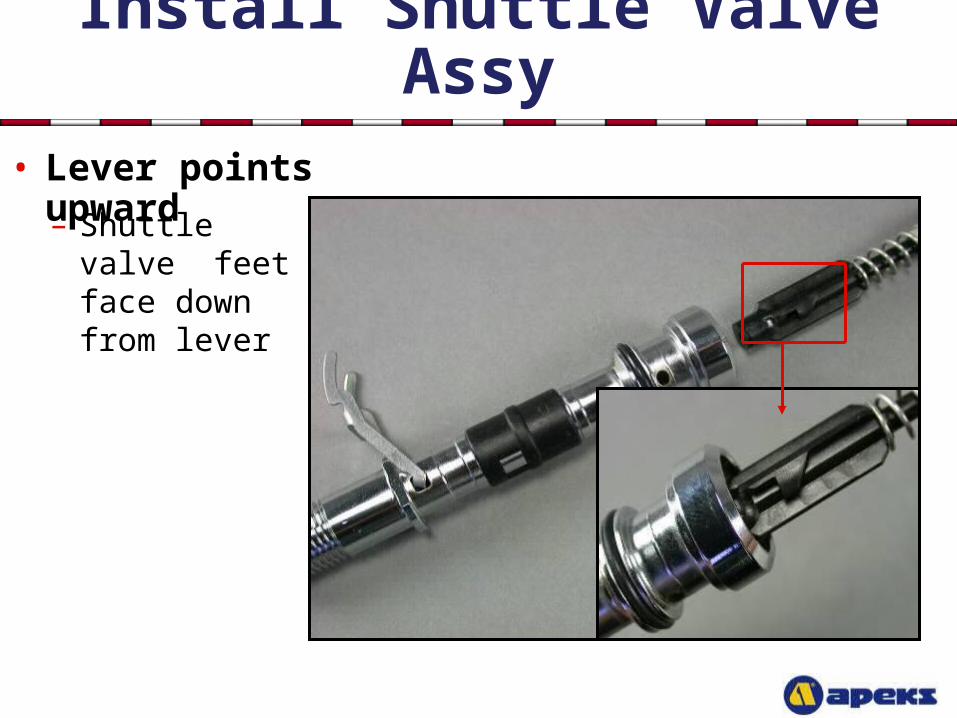
Install Shuttle Valve Assy• Lever points upward
– Shuttle valve feet face down from lever
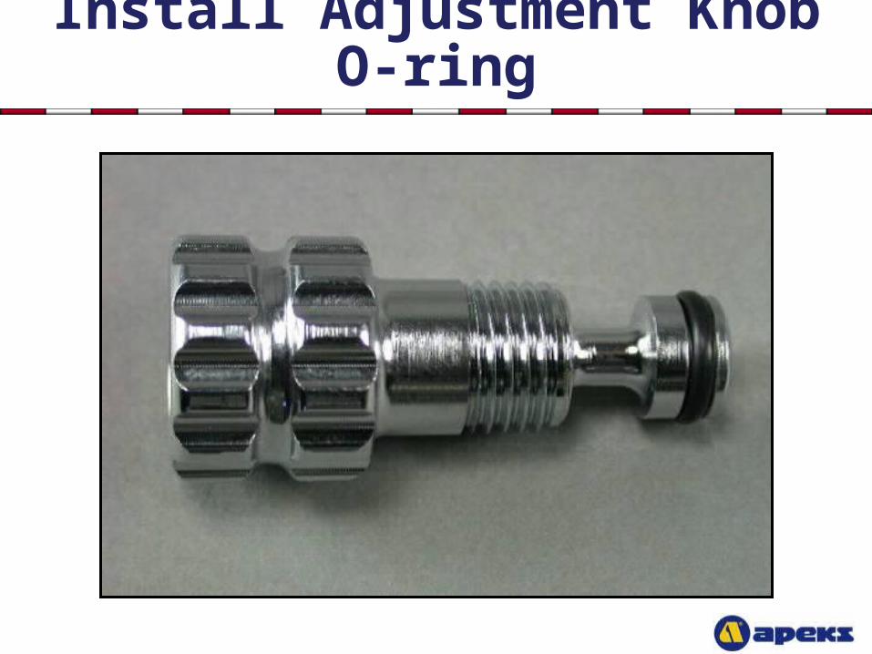
Install Adjustment Knob O-ring
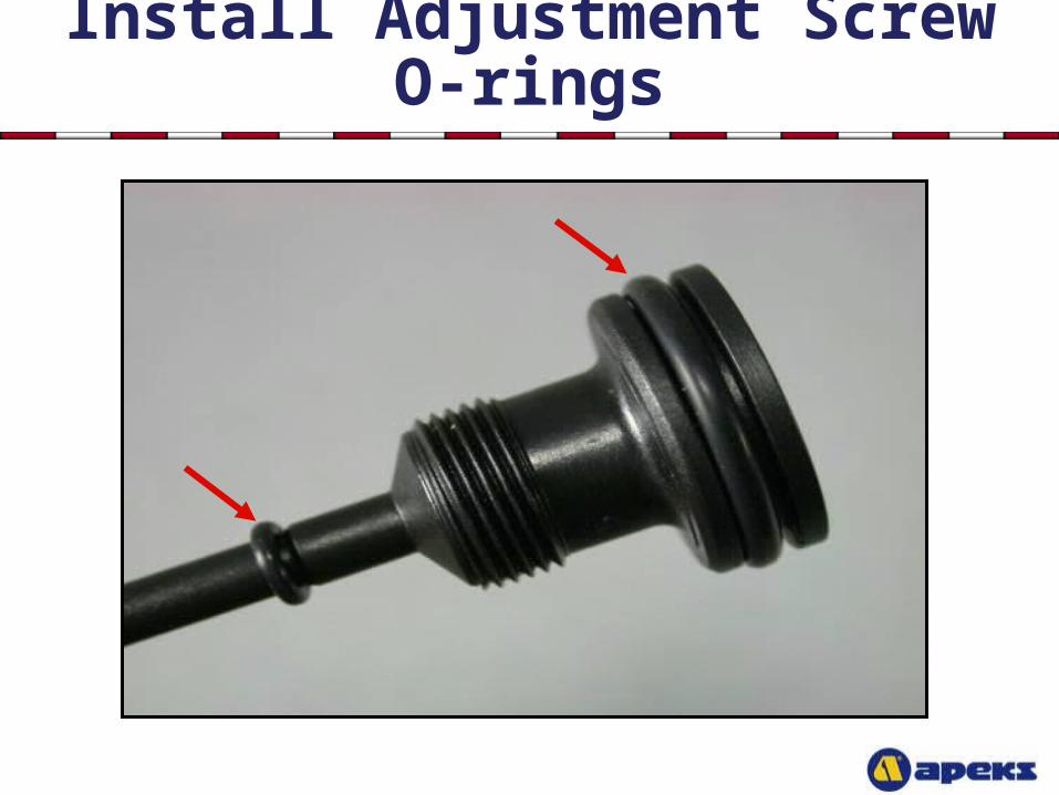
Install Adjustment Screw O-rings
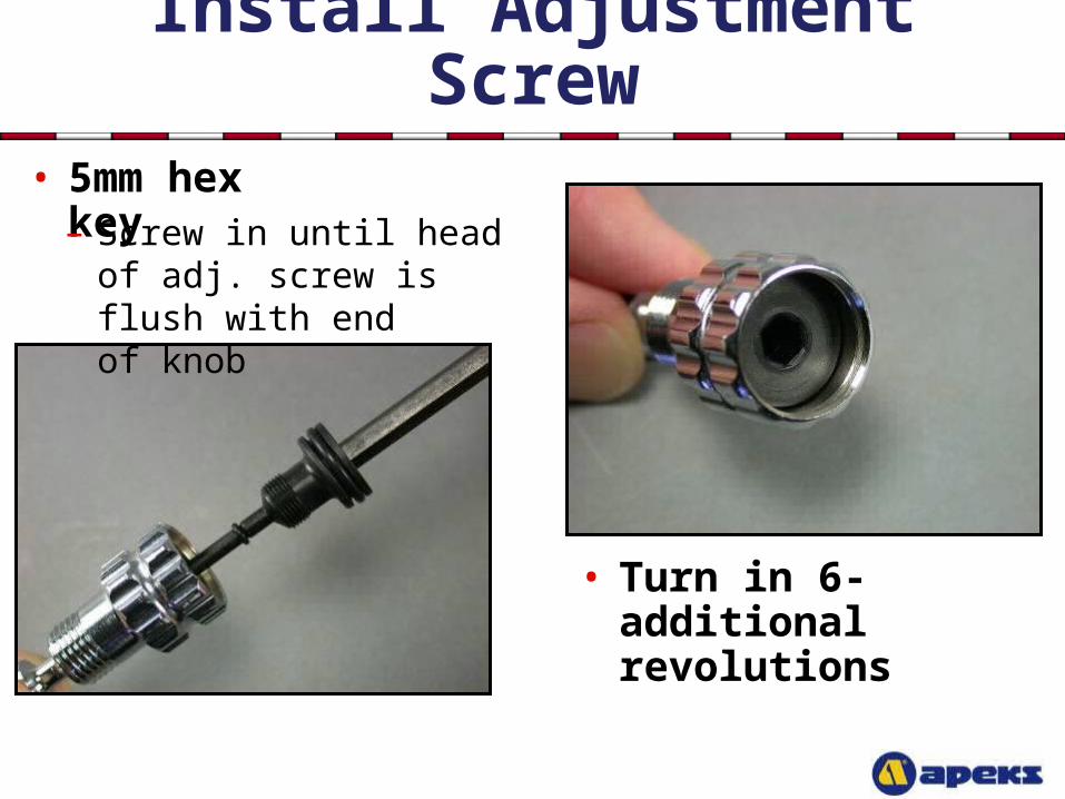
Install Adjustment Screw• 5mm hex key
• Turn in 6-additional revolutions
– Screw in until head of adj. screw is flush with end of knob
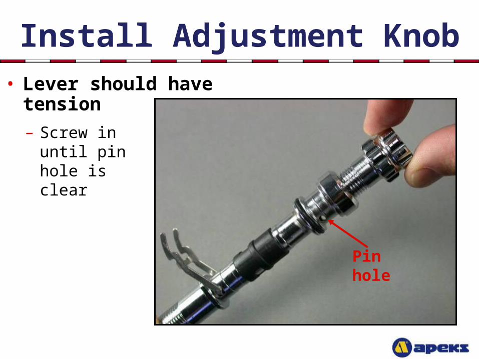
Install Adjustment Knob• Lever should have
tension – Screw in until
pin hole is clear
Pin hole
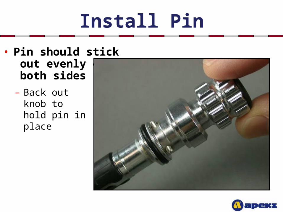
Install Pin
• Pin should stick out evenly on both sides – Back out knob
to hold pin in place
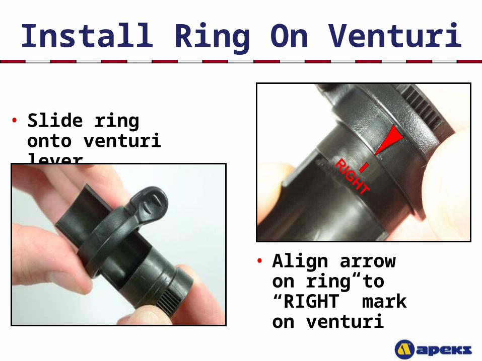
Install Ring On Venturi
• Slide ring onto venturi lever
• Align arrow on ring to “RIGHT” mark on venturi
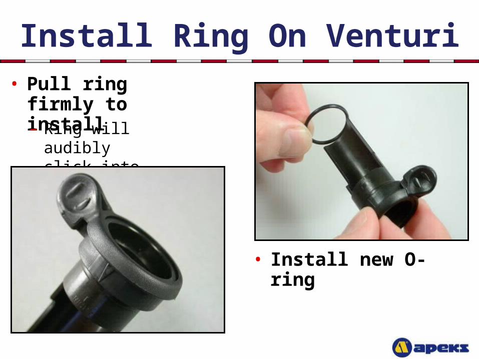
Install Ring On Venturi
• Install new O-ring
• Pull ring firmly to install
– Ring will audibly click into place
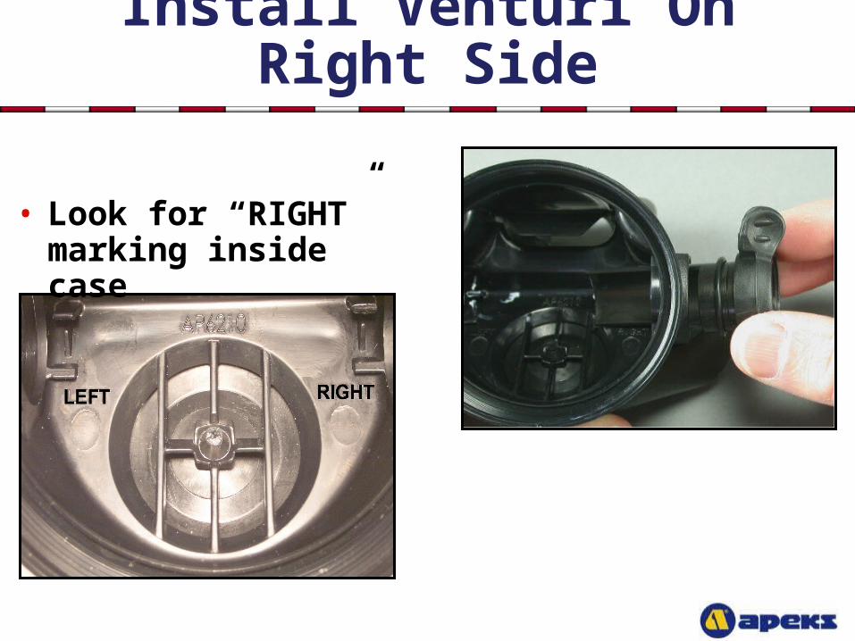
Install Venturi On Right Side
• Look for “RIGHT” marking inside case
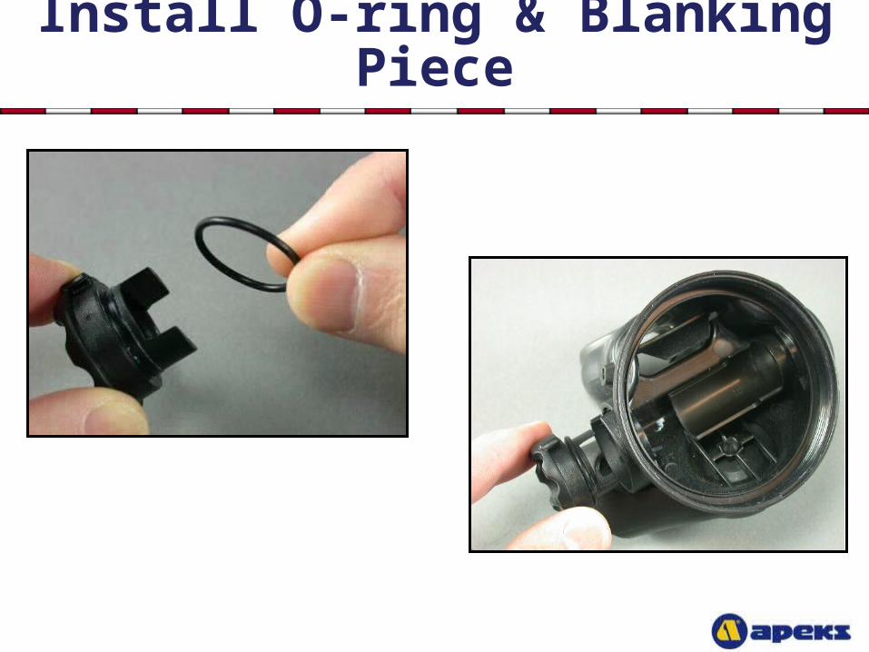
Install O-ring & Blanking Piece
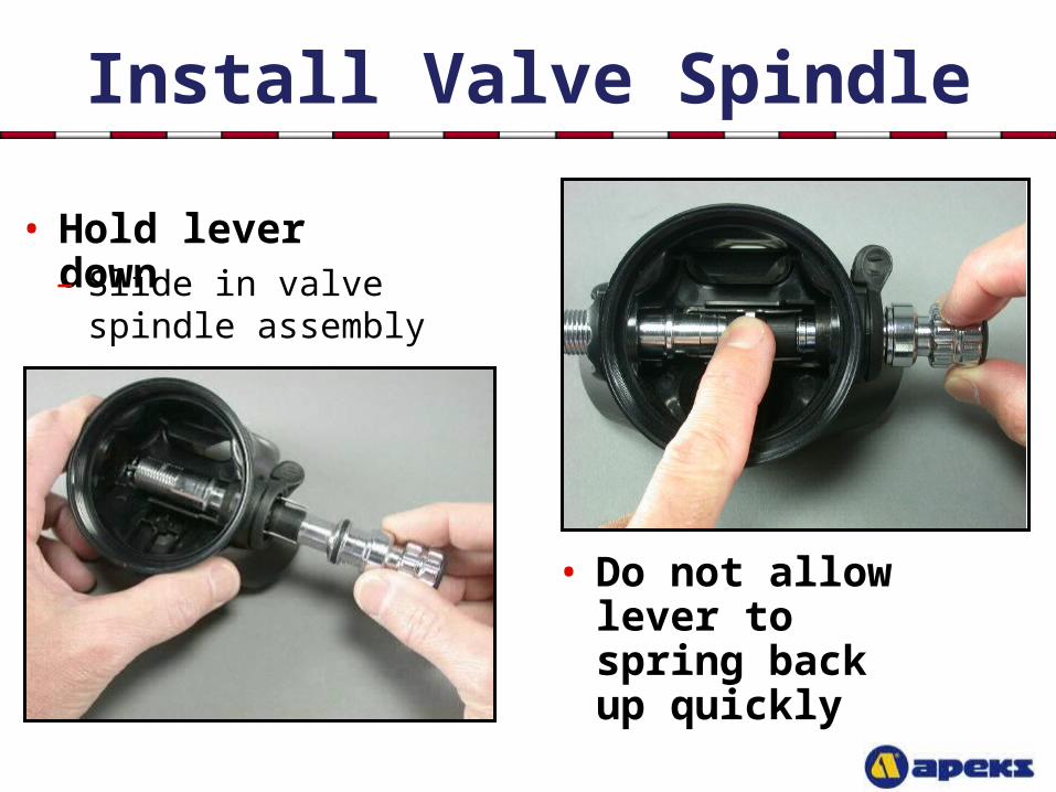
Install Valve Spindle
• Hold lever down
– Slide in valve spindle assembly
• Do not allow lever to spring back up quickly
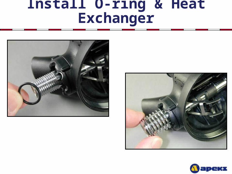
Install O-ring & Heat Exchanger
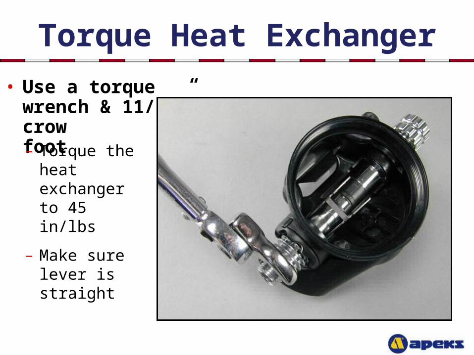
Torque Heat Exchanger
• Use a torque wrench & 11/16” crow foot – Torque the
heat exchanger to 45 in/lbs
– Make sure lever is straight
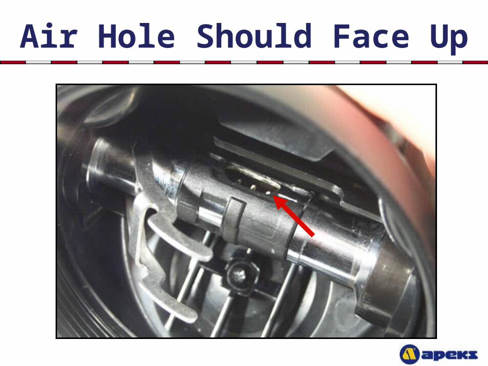
Air Hole Should Face Up
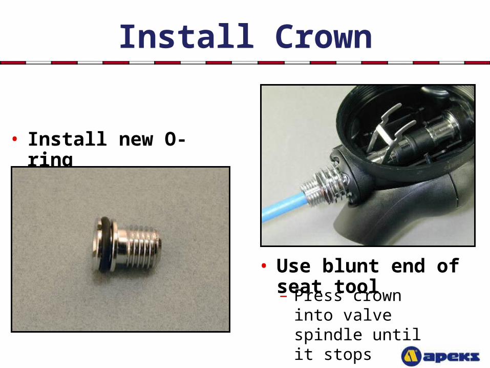
Install Crown
• Install new O-ring
• Use blunt end of seat tool
– Press crown into valve spindle until it stops
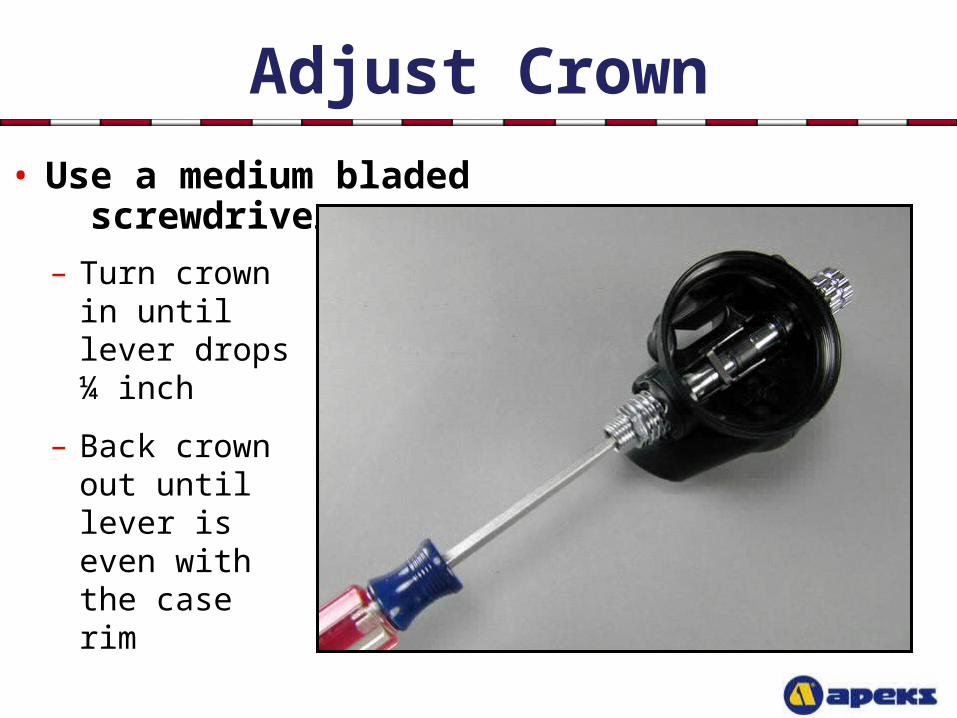
Adjust Crown
• Use a medium bladed screwdriver
– Turn crown in until lever drops ¼ inch
– Back crown out until lever is even with the case rim
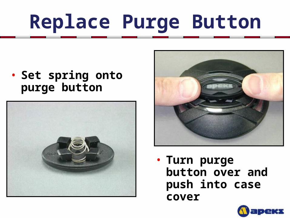
Replace Purge Button
• Turn purge button over and push into case cover
• Set spring onto purge button
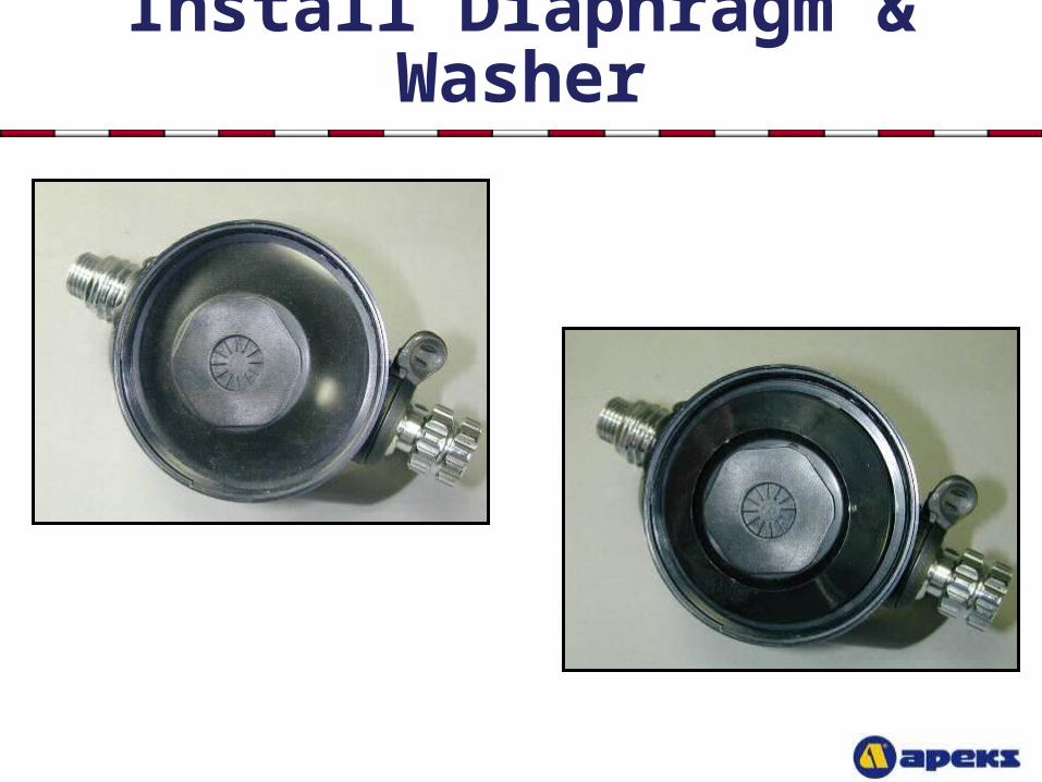
Install Diaphragm & Washer
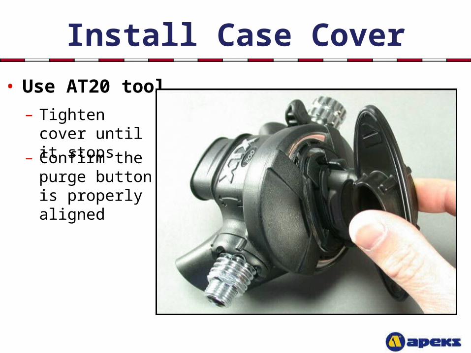
Install Case Cover
• Use AT20 tool
– Confirm the purge button is properly aligned
– Tighten cover until it stops
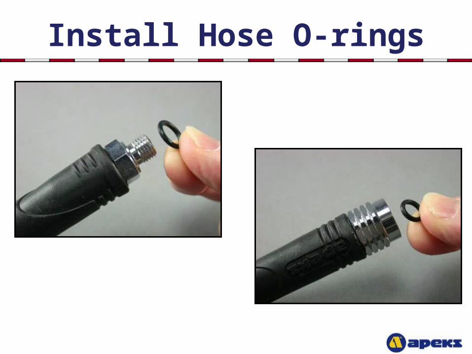
Install Hose O-rings
Final Testing
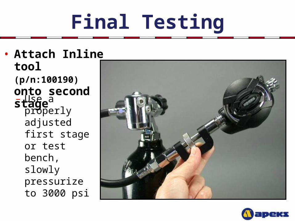
• Attach Inline tool (p/n:100190) onto second stage
– Use a properly adjusted first stage or test bench, slowly pressurize to 3000 psi
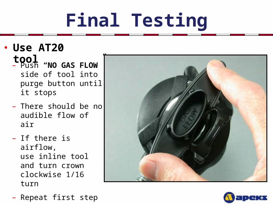
Final Testing• Use AT20 tool
– Push “NO GAS FLOW” side of tool into purge button until it stops
– There should be no audible flow of air
– If there is airflow, use inline tool and turn crown clockwise 1/16 turn
– Repeat first step
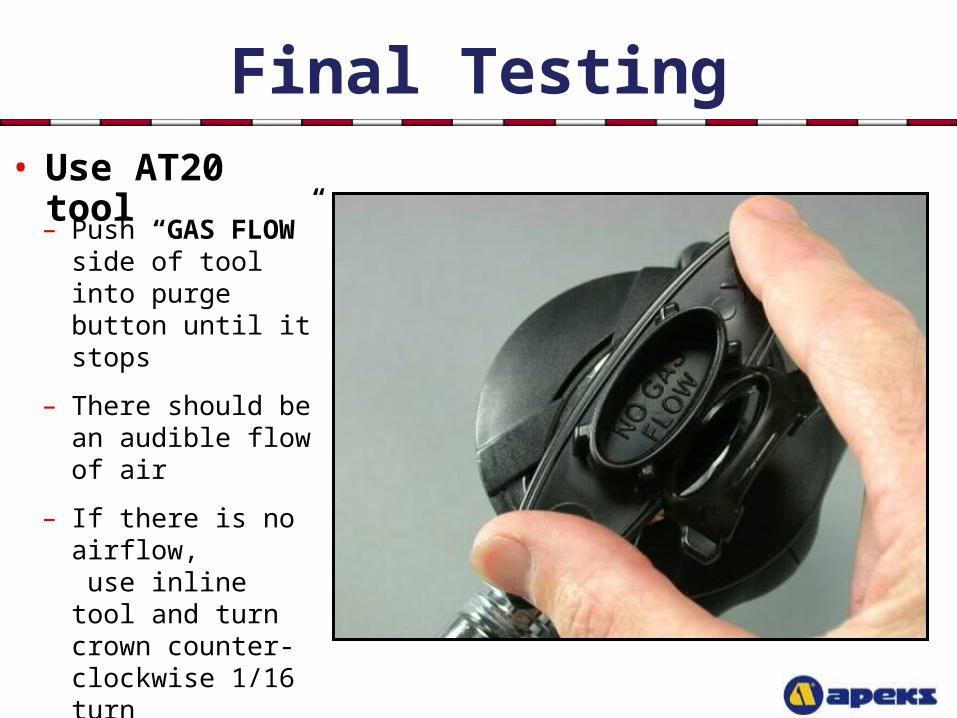
Final Testing• Use AT20 tool
– Push “GAS FLOW” side of tool into purge button until it stops
– There should be an audible flow of air
– If there is no airflow, use inline tool and turn crown counter- clockwise 1/16 turn
– Repeat first step
Final Testing
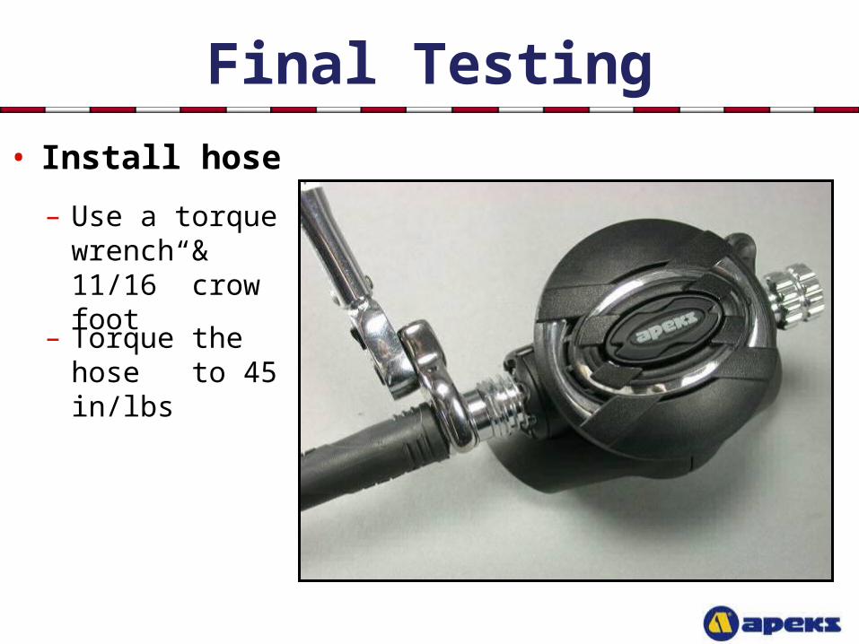
• Install hose
– Torque the hose to 45 in/lbs
– Use a torque wrench & 11/16” crow foot
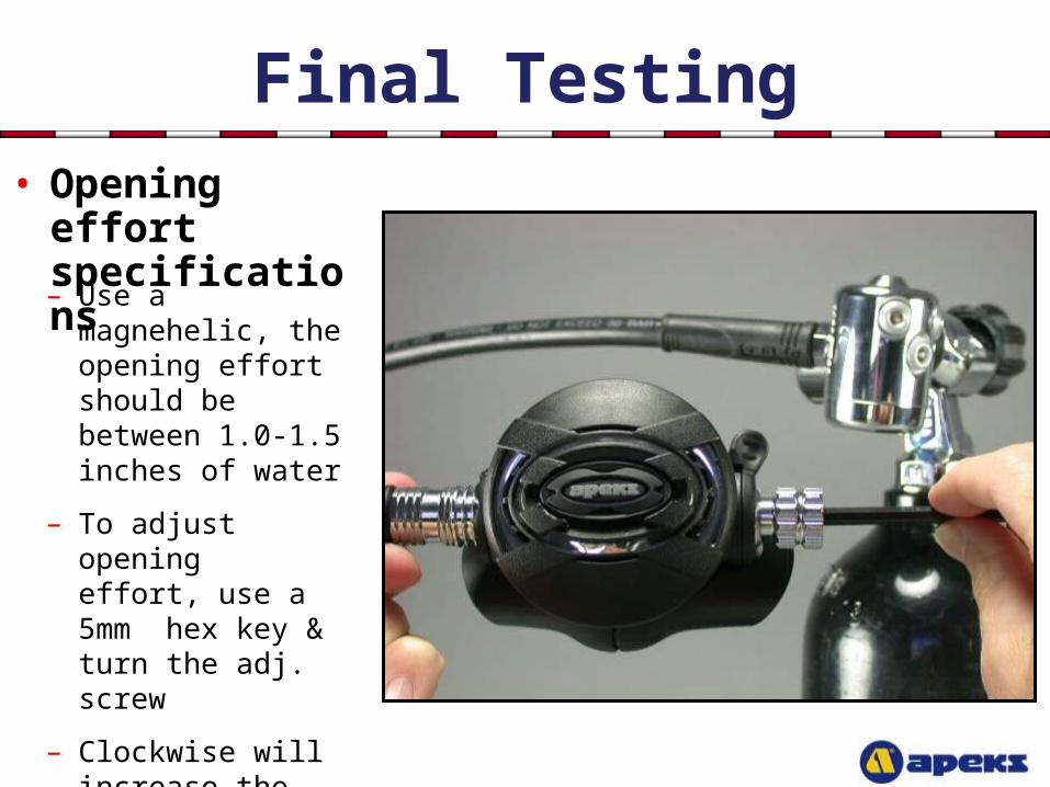
Final Testing• Opening effort
specifications
– Use a magnehelic, the opening effort should be between 1.0-1.5 inches of water
– To adjust opening effort, use a 5mm hex key & turn the adj. screw
– Clockwise will increase the effort
– Counter-clockwise will decrease the effort
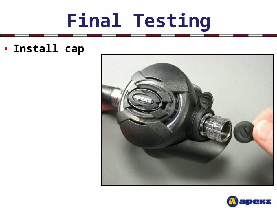
Final Testing• Install cap
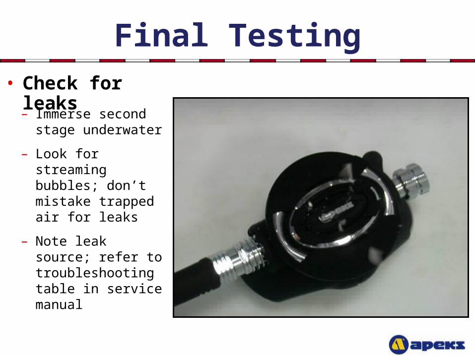
Final Testing• Check for leaks
– Immerse second stage underwater
– Look for streaming bubbles; don’t mistake trapped air for leaks
– Note leak source; refer to troubleshooting table in service manual
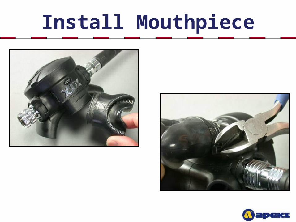
Install Mouthpiece

This Concludes The XTX Repair Course