Embed Size (px)
Citation preview
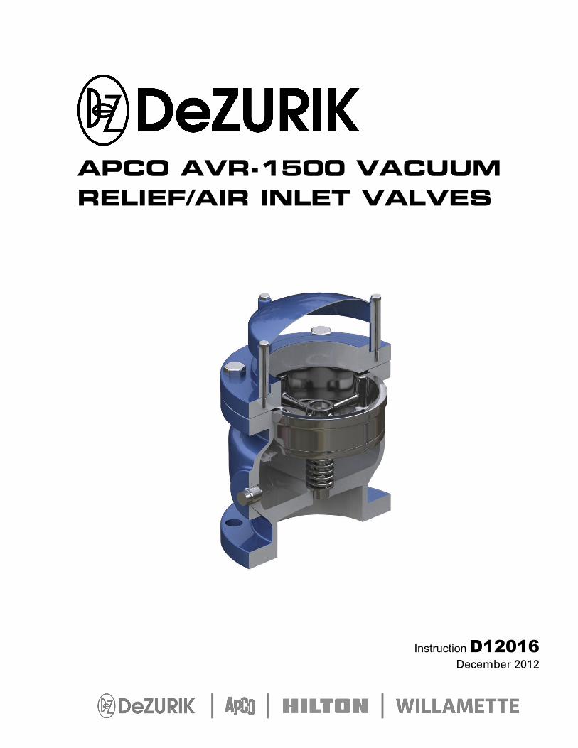
APCO AVR-1500 VACUUM RELIEF/AIR INLET VALVES
Instruction D12016 December 2012
DeZURIK APCO AVR-1500 Vacuum Relief/Air Inlet Valves
D12016 Page 2 © 2012 DeZURIK, Inc.
Instructions These instructions provide installation, operation and maintenance information for APCO AVR-1500 Vacuum Relief/Air Inlet Valves. They are for use by personnel who are responsible for installation, operation and maintenance of APCO AVR-1500 Vacuum Relief/Air Inlet Valves.
Safety Messages All safety messages in the instructions are flagged with an exclamation symbol and the word Caution, Warning or Danger. These messages indicate procedures that must be followed exactly to avoid equipment damage, personal injury or death. Safety label(s) on the product indicate hazards that can cause equipment damage, personal injury or death.
Safety label(s) on the product indicate hazards that can cause equipment damage, personal injury or death. If a safety label becomes difficult to see or read, or if a label has been removed, please contact DeZURIK for replacement label(s).
Personnel involved in the installation or maintenance of valves should be constantly alert to potential emission of pipeline material and take appropriate safety precautions. Always wear suitable protection when dealing with hazardous pipeline materials. Handle valves, which have been removed from service with suitable protection for any potential pipeline material in the valve.
Inspection Your APCO AVR-1500 Vacuum Relief/Air Inlet Valve has been packaged to provide protection during shipment; however, it can be damaged in transport. Carefully inspect the unit for damage upon arrival and file a claim with the carrier if damage is apparent.
Parts Recommended spare parts are listed on the assembly drawing. These parts should be stocked to minimize downtime. Order parts from your local DeZURIK sales representative, or directly from DeZURIK. When ordering parts please choose from the following:
If the valve has a DeZURIK APCO nameplate please include the 7-digit part number and 4-digit revision number (example: 9999999R000) located on the data plate attached to the valve assembly. Also include the part name, the assembly drawing number, the balloon number and the quantity stated on the assembly drawing.
If there isn't any nameplate visible on the valve, please include Valve Model number, the part name, and item number from the assembly drawing. You may contact your local DeZURIK APCO Representative to help you identify your valve.
DeZURIK Service DeZURIK service personnel are available to maintain and repair all DeZURIK products. DeZURIK also offers customized training programs and consultation services.
For more information, contact your local DeZURIK sales representative or visit our website at www.dezurik.com.
DeZURIK APCO AVR-1500 Vacuum Relief/Air Inlet Valves
December 2012 Page 3 D12016
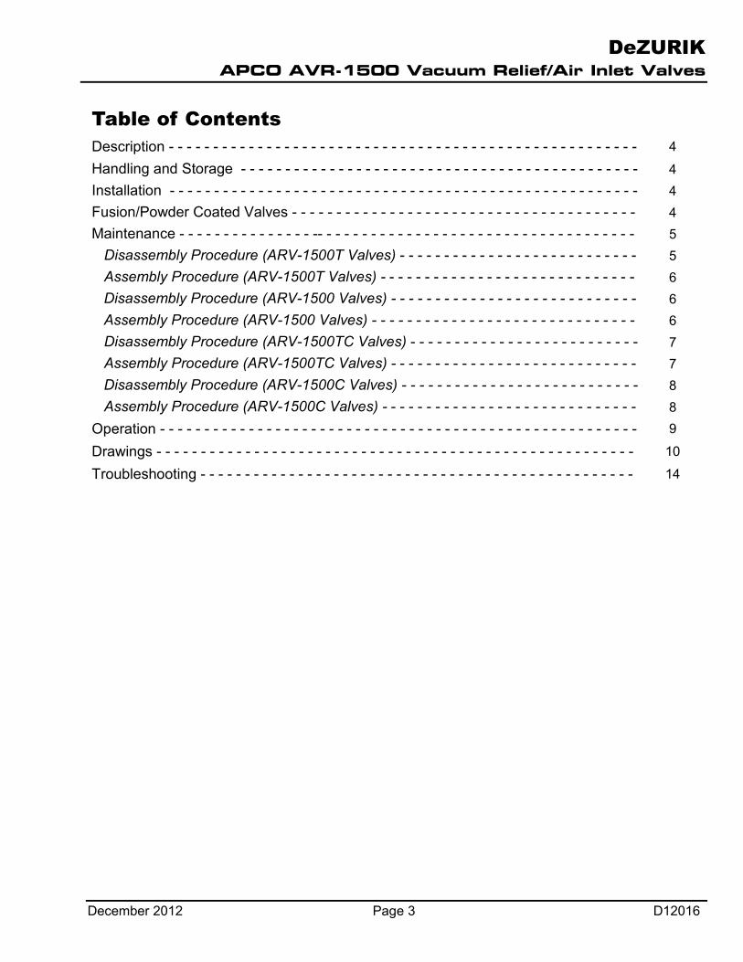
Table of Contents Description - - - - - - - - - - - - - - - - - - - - - - - - - - - - - - - - - - - - - - - - - - - - - - - - - - - - - 4
Handling and Storage - - - - - - - - - - - - - - - - - - - - - - - - - - - - - - - - - - - - - - - - - - - - - 4 Installation - - - - - - - - - - - - - - - - - - - - - - - - - - - - - - - - - - - - - - - - - - - - - - - - - - - - - 4 Fusion/Powder Coated Valves - - - - - - - - - - - - - - - - - - - - - - - - - - - - - - - - - - - - - - - 4 Maintenance - - - - - - - - - - - - - - - -- - - - - - - - - - - - - - - - - - - - - - - - - - - - - - - - - - - - 5 Disassembly Procedure (ARV-1500T Valves) - - - - - - - - - - - - - - - - - - - - - - - - - - - 5 Assembly Procedure (ARV-1500T Valves) - - - - - - - - - - - - - - - - - - - - - - - - - - - - - 6
Disassembly Procedure (ARV-1500 Valves) - - - - - - - - - - - - - - - - - - - - - - - - - - - - 6 Assembly Procedure (ARV-1500 Valves) - - - - - - - - - - - - - - - - - - - - - - - - - - - - - - 6
Disassembly Procedure (ARV-1500TC Valves) - - - - - - - - - - - - - - - - - - - - - - - - - - 7 Assembly Procedure (ARV-1500TC Valves) - - - - - - - - - - - - - - - - - - - - - - - - - - - - 7
Disassembly Procedure (ARV-1500C Valves) - - - - - - - - - - - - - - - - - - - - - - - - - - - 8 Assembly Procedure (ARV-1500C Valves) - - - - - - - - - - - - - - - - - - - - - - - - - - - - - 8 Operation - - - - - - - - - - - - - - - - - - - - - - - - - - - - - - - - - - - - - - - - - - - - - - - - - - - - - - 9
Drawings - - - - - - - - - - - - - - - - - - - - - - - - - - - - - - - - - - - - - - - - - - - - - - - - - - - - - - 10
Troubleshooting - - - - - - - - - - - - - - - - - - - - - - - - - - - - - - - - - - - - - - - - - - - - - - - - - 14
DeZURIK APCO AVR-1500 Vacuum Relief/Air Inlet Valves
D12016 Page 4 December 2012
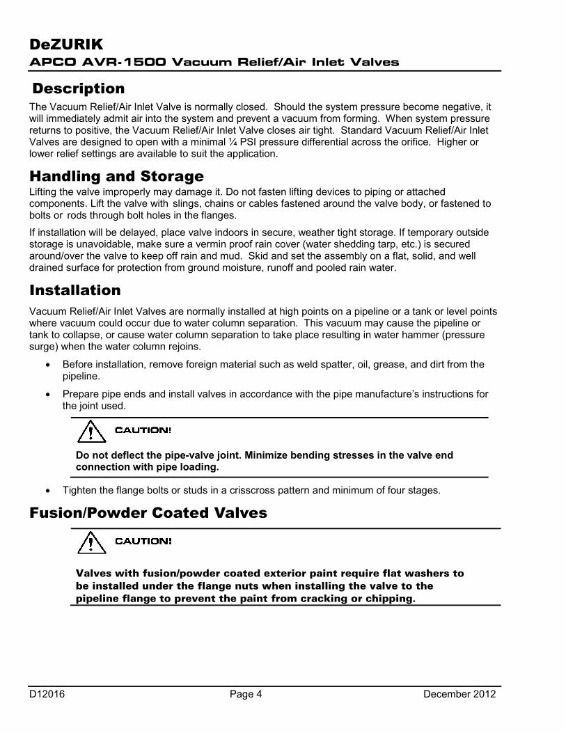
Description The Vacuum Relief/Air Inlet Valve is normally closed. Should the system pressure become negative, it will immediately admit air into the system and prevent a vacuum from forming. When system pressure returns to positive, the Vacuum Relief/Air Inlet Valve closes air tight. Standard Vacuum Relief/Air Inlet Valves are designed to open with a minimal ¼ PSI pressure differential across the orifice. Higher or lower relief settings are available to suit the application.
Handling and Storage Lifting the valve improperly may damage it. Do not fasten lifting devices to piping or attached components. Lift the valve with slings, chains or cables fastened around the valve body, or fastened to bolts or rods through bolt holes in the flanges.
If installation will be delayed, place valve indoors in secure, weather tight storage. If temporary outside storage is unavoidable, make sure a vermin proof rain cover (water shedding tarp, etc.) is secured around/over the valve to keep off rain and mud. Skid and set the assembly on a flat, solid, and well drained surface for protection from ground moisture, runoff and pooled rain water.
Installation Vacuum Relief/Air Inlet Valves are normally installed at high points on a pipeline or a tank or level points where vacuum could occur due to water column separation. This vacuum may cause the pipeline or tank to collapse, or cause water column separation to take place resulting in water hammer (pressure surge) when the water column rejoins.
• Before installation, remove foreign material such as weld spatter, oil, grease, and dirt from the pipeline.
• Prepare pipe ends and install valves in accordance with the pipe manufacture’s instructions for the joint used.
Do not deflect the pipe-valve joint. Minimize bending stresses in the valve end connection with pipe loading.
• Tighten the flange bolts or studs in a crisscross pattern and minimum of four stages.
Fusion/Powder Coated Valves
Valves with fusion/powder coated exterior paint require flat washers to be installed under the flange nuts when installing the valve to the pipeline flange to prevent the paint from cracking or chipping.

DeZURIK APCO AVR-1500 Vacuum Relief/Air Inlet Valves
December 2012 Page 5 D12016
Maintenance The APCO AVR-1500 Vacuum Relief/Air Inlet Valve is automatic in operation and requires little or no maintenance. It is recommended that it be checked visually semi-annually for leakage. A malfunction of the valve can be identified by seepage of the media through the exhaust port. If a malfunction occurs, the following steps should be taken to repair the valve;
Disassembly Procedure (AVR-1500T Valves) See Figure 1 for part identification.
Servicing the Air Valve while the pipeline is under pressure can cause personal injury or equipment damage. Relieve pipeline pressure or shut off isolation valve before servicing the Air Valve.
1. Relieve pipeline pressure or shut off isolation valve before servicing the Air Valve.
Do not completely remove pipe plug or cover screws while the valve is under pressure.
2. Loosen pipe plug (17) to allow internal pressure to escape.
3. Remove cover screws (4), cover (2) and cover gasket (3).
4. Remove baffle screws (34) and baffle (24), and lift out seat (6) from the recess in the cover (2).
5. Remove float (14), spring (42), float guide (33) and baffle plug (41) from baffle (24).
6. Clean all surfaces before re-assembly. Replace all defective parts.
Assembly Procedure (AVR-1500T Valves) 1. Install baffle plug (41), float guide (33), spring (42) and float (14) to baffle (24). Replace new
parts if any are damaged.
2. Install seat (6) into cover (2) and align holes. Replace old seat if damaged. Buna-N seat hardness (Durometer) should correspond to the operating pressure shown in Table A.
Table A: Buna-N Seat Hardness (Durometer)
Valve Size
Working Pressure, psi 0-10 11-50 51-100 101-200 201-300
½” 20 45 45 45 85 1” 45 65 65 65 85 2” 45 65 85 85 85 3” 45 65 85 85 85
3. With cover (2) lying upside down, set the baffle (24) assembly on seat (6). Align both seat
and baffle holes and replace seat screws (7). Do not tighten seat screws.
DeZURIK APCO AVR-1500 Vacuum Relief/Air Inlet Valves
D12016 Page 6 December 2012
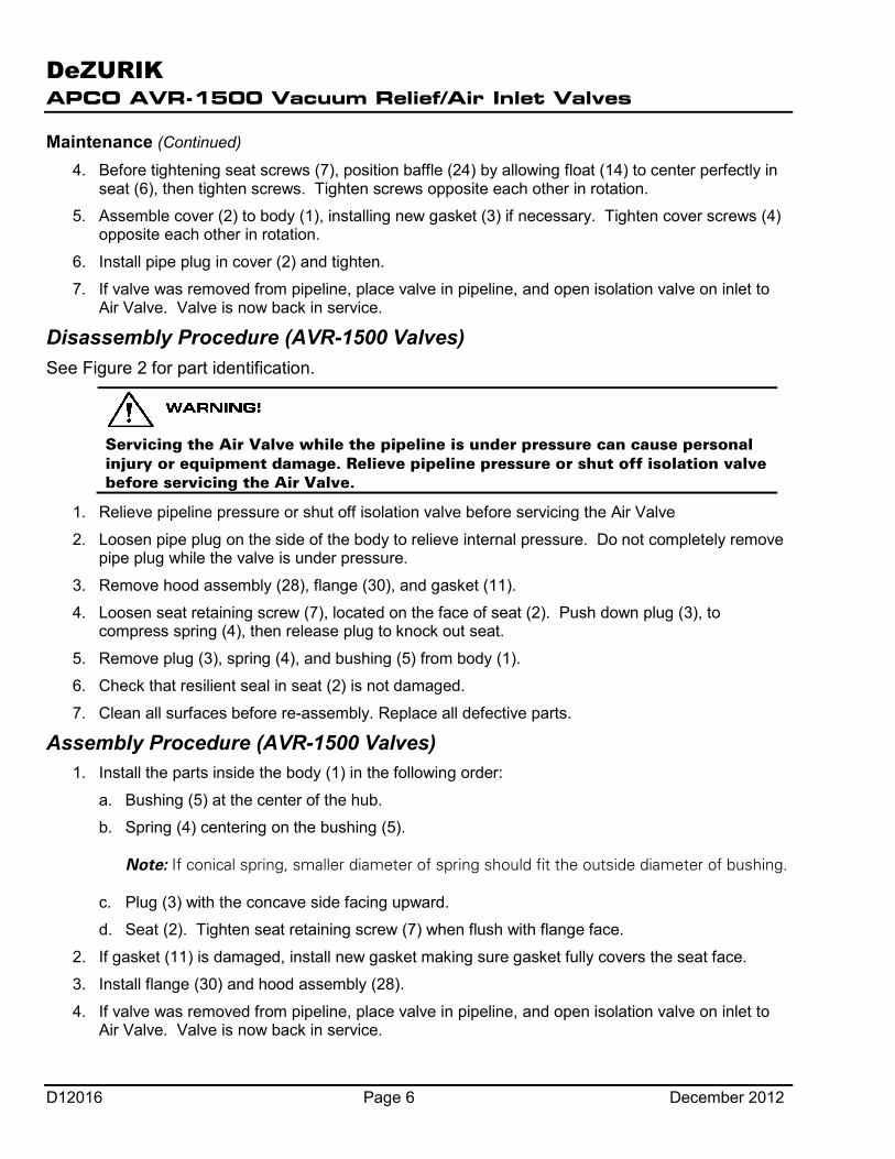
Maintenance (Continued)
4. Before tightening seat screws (7), position baffle (24) by allowing float (14) to center perfectly in seat (6), then tighten screws. Tighten screws opposite each other in rotation.
5. Assemble cover (2) to body (1), installing new gasket (3) if necessary. Tighten cover screws (4) opposite each other in rotation.
6. Install pipe plug in cover (2) and tighten.
7. If valve was removed from pipeline, place valve in pipeline, and open isolation valve on inlet to Air Valve. Valve is now back in service.
Disassembly Procedure (AVR-1500 Valves) See Figure 2 for part identification.
Servicing the Air Valve while the pipeline is under pressure can cause personal injury or equipment damage. Relieve pipeline pressure or shut off isolation valve before servicing the Air Valve.
1. Relieve pipeline pressure or shut off isolation valve before servicing the Air Valve
2. Loosen pipe plug on the side of the body to relieve internal pressure. Do not completely remove pipe plug while the valve is under pressure.
3. Remove hood assembly (28), flange (30), and gasket (11).
4. Loosen seat retaining screw (7), located on the face of seat (2). Push down plug (3), to compress spring (4), then release plug to knock out seat.
5. Remove plug (3), spring (4), and bushing (5) from body (1).
6. Check that resilient seal in seat (2) is not damaged.
7. Clean all surfaces before re-assembly. Replace all defective parts.
Assembly Procedure (AVR-1500 Valves) 1. Install the parts inside the body (1) in the following order:
a. Bushing (5) at the center of the hub.
b. Spring (4) centering on the bushing (5). Note: If conical spring, smaller diameter of spring should fit the outside diameter of bushing.
c. Plug (3) with the concave side facing upward.
d. Seat (2). Tighten seat retaining screw (7) when flush with flange face.
2. If gasket (11) is damaged, install new gasket making sure gasket fully covers the seat face.
3. Install flange (30) and hood assembly (28).
4. If valve was removed from pipeline, place valve in pipeline, and open isolation valve on inlet to Air Valve. Valve is now back in service.
DeZURIK APCO AVR-1500 Vacuum Relief/Air Inlet Valves
December 2012 Page 7 D12016
Maintenance (Continued)
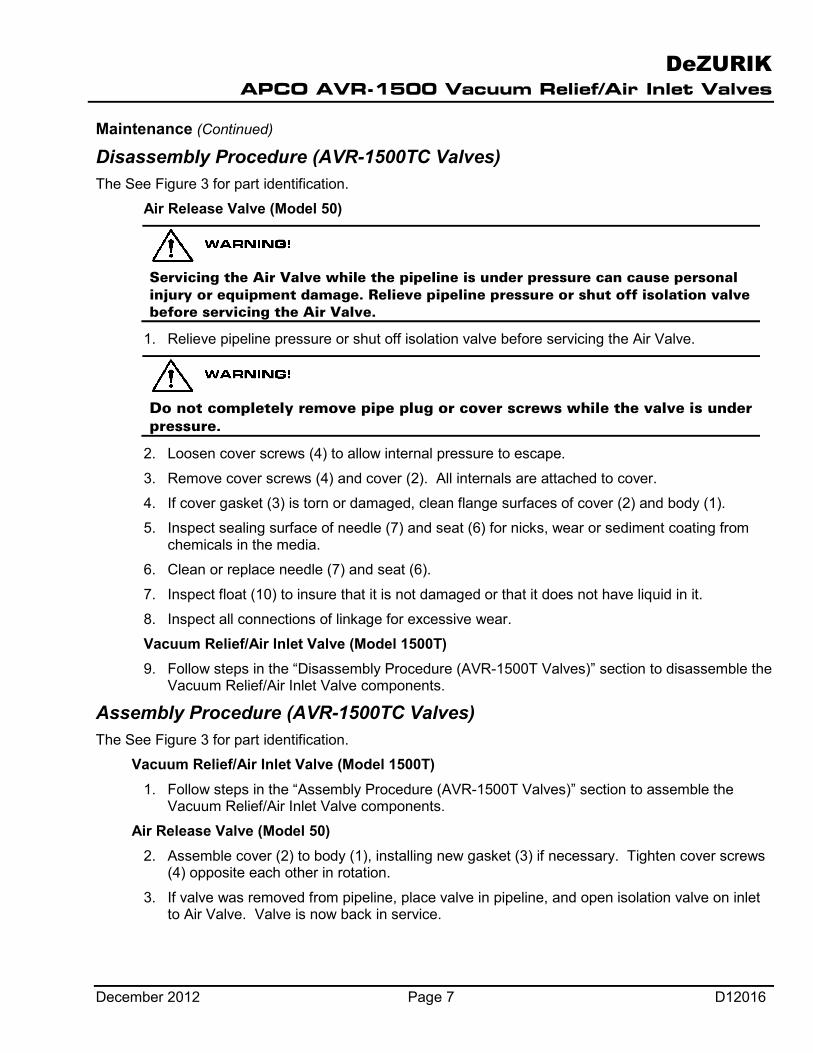
Disassembly Procedure (AVR-1500TC Valves) The See Figure 3 for part identification.
Air Release Valve (Model 50)
Servicing the Air Valve while the pipeline is under pressure can cause personal injury or equipment damage. Relieve pipeline pressure or shut off isolation valve before servicing the Air Valve.
1. Relieve pipeline pressure or shut off isolation valve before servicing the Air Valve.
Do not completely remove pipe plug or cover screws while the valve is under pressure.
2. Loosen cover screws (4) to allow internal pressure to escape.
3. Remove cover screws (4) and cover (2). All internals are attached to cover.
4. If cover gasket (3) is torn or damaged, clean flange surfaces of cover (2) and body (1).
5. Inspect sealing surface of needle (7) and seat (6) for nicks, wear or sediment coating from chemicals in the media.
6. Clean or replace needle (7) and seat (6).
7. Inspect float (10) to insure that it is not damaged or that it does not have liquid in it.
8. Inspect all connections of linkage for excessive wear.
Vacuum Relief/Air Inlet Valve (Model 1500T) 9. Follow steps in the “Disassembly Procedure (AVR-1500T Valves)” section to disassemble the
Vacuum Relief/Air Inlet Valve components.
Assembly Procedure (AVR-1500TC Valves) The See Figure 3 for part identification.
Vacuum Relief/Air Inlet Valve (Model 1500T) 1. Follow steps in the “Assembly Procedure (AVR-1500T Valves)” section to assemble the
Vacuum Relief/Air Inlet Valve components.
Air Release Valve (Model 50) 2. Assemble cover (2) to body (1), installing new gasket (3) if necessary. Tighten cover screws
(4) opposite each other in rotation.
3. If valve was removed from pipeline, place valve in pipeline, and open isolation valve on inlet to Air Valve. Valve is now back in service.
DeZURIK APCO AVR-1500 Vacuum Relief/Air Inlet Valves
D12016 Page 8 December 2012
Maintenance (Continued)
Disassembly Procedure (AVR-1500C Valves) See Figure 4 for part identification.
Air Release Valve (Model 50, 200 or 200A)
Servicing the Air Valve while the pipeline is under pressure can cause personal injury or equipment damage. Relieve pipeline pressure or shut off isolation valve before servicing the Air Valve.
2. Relieve pipeline pressure or shut off isolation valve before servicing the Air Valve.
Do not completely remove pipe plug or cover screws while the valve is under pressure.
3. Loosen pipe plug or cover screws (4) to allow internal pressure to escape.
4. Remove cover screws (4) and cover (2). All internals are attached to cover.
5. If cover gasket (3) is torn or damaged, clean flange surfaces of cover (2) and body (1).
6. Inspect sealing surface of needle (7) and seat (6) for nicks, wear or sediment coating from chemicals in the media.
7. Clean or replace needle (7) and seat (6).
8. Inspect float (10) to insure that it is not damaged or that it does not have liquid in it.
9. Inspect all connections of linkage for excessive wear.
Vacuum Relief/Air Inlet Valve (Model 1500) 10. Follow steps in the “Disassembly Procedure (AVR-1500 Valves)” section to disassemble the
Vacuum Relief/Air Inlet Valve components.
Assembly Procedure (AVR-1500C Valves) See Figure 4 for part identification.
Vacuum Relief/Air Inlet Valve (Model 1500) 1. Follow steps in the “Assembly Procedure (AVR-1500 Valves)” section to assemble the
Vacuum Relief/Air Inlet Valve components.
Air Release Valve (Model 50, 200 or 200A) 2. Assemble cover (2) to body (1), installing new gasket (3) if necessary. Tighten cover screws
(4) opposite each other in rotation.
3. Tighten pipe plug if required.
4. If valve was removed from pipeline, place valve in pipeline, and open isolation valve on inlet to Air Valve. Valve is now back in service.
DeZURIK APCO AVR-1500 Vacuum Relief/Air Inlet Valves
December 2012 Page 9 D12016
Operation The Vacuum Relief/Air Inlet Valve is normally closed. Should the system pressure become negative, it will immediately admit air into the system and prevent a vacuum from forming. When system pressure returns to positive, the Vacuum Relief/Air Inlet Valve closes air tight. Standard Vacuum Relief/Air Inlet Valves are designed to open with a minimal ¼ PSI pressure differential across the orifice. Higher or lower relief settings are available to suit the application.
DeZURIK APCO AVR-1500 Vacuum Relief/Air Inlet Valves
D12016 Page 10 December 2012
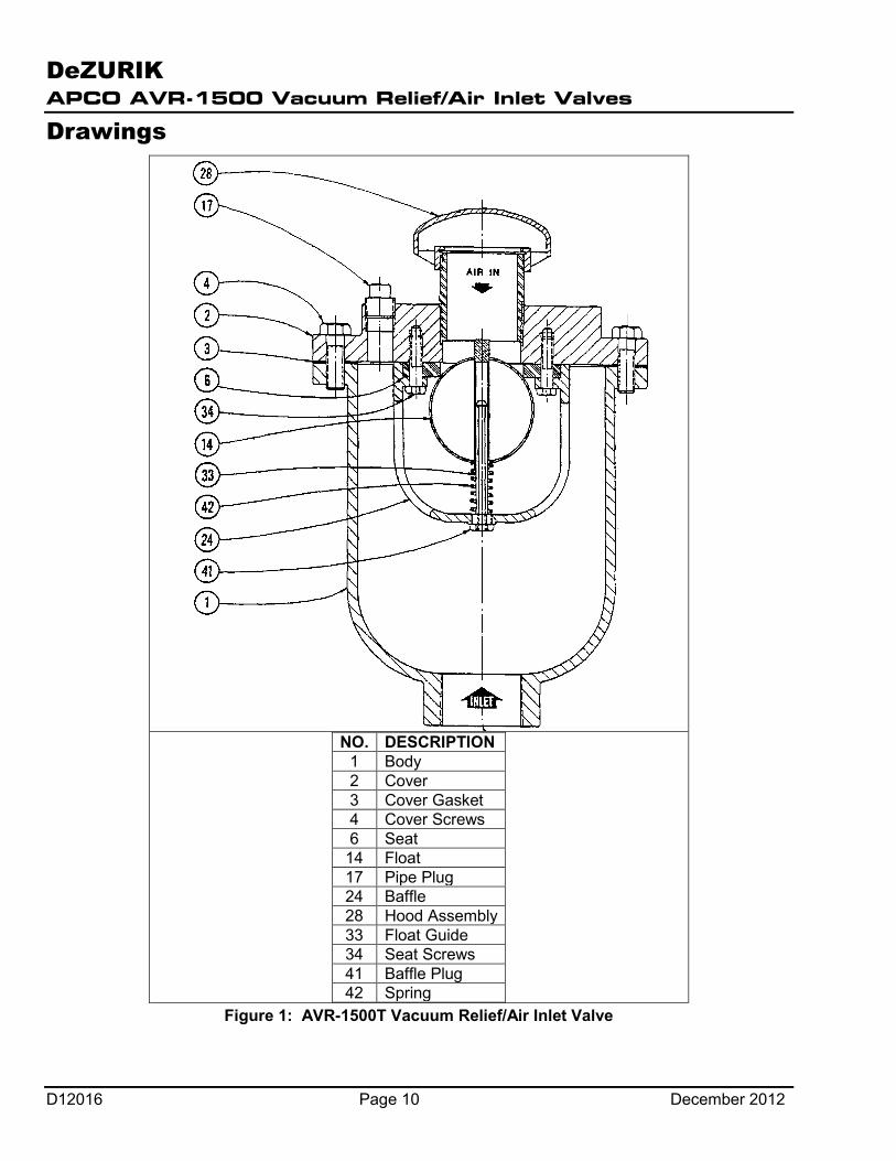
Drawings
NO. DESCRIPTION
1 Body 2 Cover 3 Cover Gasket 4 Cover Screws 6 Seat
14 Float 17 Pipe Plug 24 Baffle 28 Hood Assembly 33 Float Guide 34 Seat Screws 41 Baffle Plug 42 Spring
Figure 1: AVR-1500T Vacuum Relief/Air Inlet Valve
DeZURIK APCO AVR-1500 Vacuum Relief/Air Inlet Valves
December 2012 Page 11 D12016
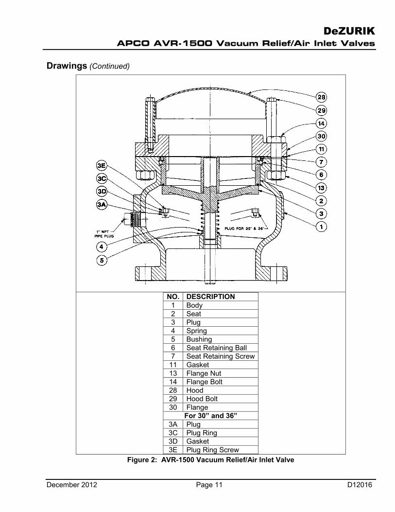
Drawings (Continued)
NO. DESCRIPTION 1 Body 2 Seat 3 Plug 4 Spring 5 Bushing 6 Seat Retaining Ball 7 Seat Retaining Screw
11 Gasket 13 Flange Nut 14 Flange Bolt 28 Hood 29 Hood Bolt 30 Flange
For 30” and 36” 3A Plug 3C Plug Ring 3D Gasket 3E Plug Ring Screw
Figure 2: AVR-1500 Vacuum Relief/Air Inlet Valve
DeZURIK APCO AVR-1500 Vacuum Relief/Air Inlet Valves
D12016 Page 12 December 2012
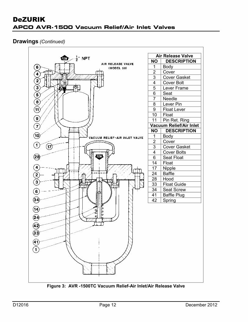
Drawings (Continued)
Air Release Valve NO DESCRIPTION 1 Body 2 Cover 3 Cover Gasket 4 Cover Bolt 5 Lever Frame 6 Seat 7 Needle 8 Lever Pin 9 Float Lever 10 Float 11 Pin Ret. Ring
Vacuum Relief/Air Inlet NO DESCRIPTION 1 Body 2 Cover 3 Cover Gasket 4 Cover Bolts 6 Seat Float 14 Float 17 Nipple 24 Baffle 28 Hood 33 Float Guide 34 Seat Screw 41 Baffle Plug 42 Spring
Figure 3: AVR -1500TC Vacuum Relief-Air Inlet/Air Release Valve
DeZURIK APCO AVR-1500 Vacuum Relief/Air Inlet Valves
December 2012 Page 13 D12016
Drawings (Continued)
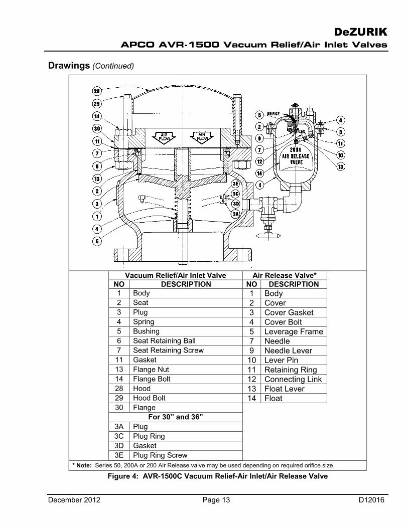
Vacuum Relief/Air Inlet Valve Air Release Valve*
NO DESCRIPTION NO DESCRIPTION 1 Body 1 Body 2 Seat 2 Cover 3 Plug 3 Cover Gasket 4 Spring 4 Cover Bolt 5 Bushing 5 Leverage Frame 6 Seat Retaining Ball 7 Needle 7 Seat Retaining Screw 9 Needle Lever 11 Gasket 10 Lever Pin 13 Flange Nut 11 Retaining Ring 14 Flange Bolt 12 Connecting Link 28 Hood 13 Float Lever 29 Hood Bolt 14 Float 30 Flange
For 30” and 36” 3A Plug 3C Plug Ring 3D Gasket 3E Plug Ring Screw
* Note: Series 50, 200A or 200 Air Release valve may be used depending on required orifice size.
Figure 4: AVR-1500C Vacuum Relief-Air Inlet/Air Release Valve
DeZURIK APCO AVR-1500 Vacuum Relief/Air Inlet Valves
D12016 Page 14 December 2012
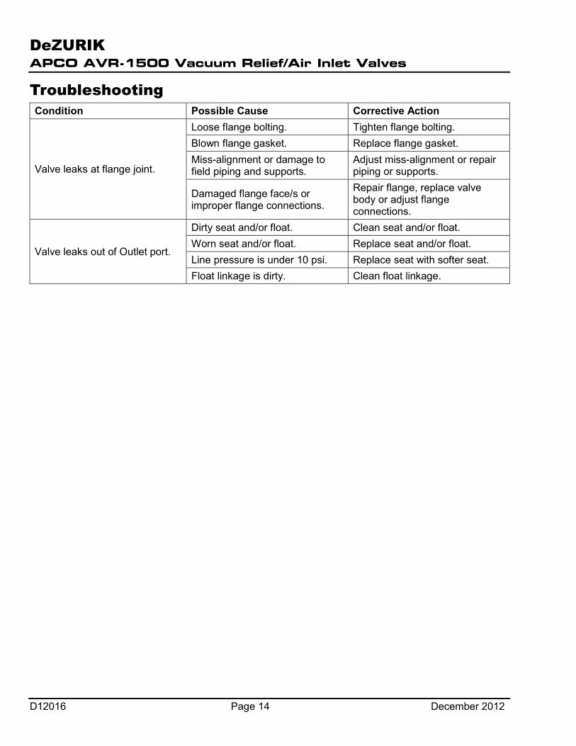
Troubleshooting Condition Possible Cause Corrective Action
Valve leaks at flange joint.
Loose flange bolting. Tighten flange bolting. Blown flange gasket. Replace flange gasket. Miss-alignment or damage to field piping and supports.
Adjust miss-alignment or repair piping or supports.
Damaged flange face/s or improper flange connections.
Repair flange, replace valve body or adjust flange connections.
Valve leaks out of Outlet port.
Dirty seat and/or float. Clean seat and/or float. Worn seat and/or float. Replace seat and/or float. Line pressure is under 10 psi. Replace seat with softer seat. Float linkage is dirty. Clean float linkage.
Printed in U.S.A.
Guarantee Products, auxiliaries and parts thereof of DeZURIK, Inc. manufacture are warranted to the original purchaser for a period of twenty-four (24) months from date of shipment from factory, against defective workmanship and material, but only if properly installed, operated and serviced in accordance with DeZURIK, Inc. recommendations. Repair or replacement, at our option, for items of DeZURIK, Inc. manufacture will be made free of charge, (FOB) our facility with removal, transportation and installation at your cost, if proved to be defective within such time, and this is your sole remedy with respect to such products. Equipment or parts manufactured by others but furnished by DeZURIK, Inc. will be repaired or replaced, but only to the extent provided in and honored by the original manufacturers warranty to DeZURIK, Inc., in each case subject to the limitations contained therein. No claim for transportation, labor or special or consequential damages or any other loss, cost or damage shall be allowed. You shall be solely responsible for determining suitability for use and in no event shall DeZURIK, Inc. be liable in this respect. DeZURIK, Inc. does not guarantee resistance to corrosion, erosion, abrasion or other sources of failure, nor does DeZURIK, Inc. guarantee a minimum length of service. Your failure to give written notice to us of any alleged defect under this warranty within twenty (20) days of its discovery, or attempts by someone other than DeZURIK, Inc. or its authorized representatives to remedy the alleged defects therein, or failure to return product or parts for repair or replacement as herein provided, or failure to install and operate said products and parts according to instructions furnished by DeZURIK, Inc., or misuse, modification, abuse or alteration of such product, accident, fire, flood or other Act of God, or failure to pay entire contract price when due shall be a waiver by you of all rights under this warranty. The foregoing guarantee shall be null and void if, after shipment from our factory, the item is modified in any way or a component of another manufacturer, such as but not limited to, an actuator is attached to the item by anyone other than DeZURIK, Inc. Factory Service personnel. All orders accepted shall be deemed accepted subject to this limited warranty, which shall be exclusive of any other or previous Warranty, and this shall be the only effective guarantee or warranty binding on DeZURIK, Inc., despite anything to the contrary contained in the purchase order or represented by any agent or employee of DeZURIK, Inc., in writing or otherwise, notwithstanding, including but not limited to implied warranties. Metric fasteners should not be used with ASME Class 150/300 bolt holes and flange bolt patterns. If you use metric fasteners with ASME Class 150/300 bolt holes and flange bolt patterns, it may lead to product failure, injury, and loss of life. DeZURIK Inc. disclaims all liability associated with the use of metric fasteners with ASME Class 150/300 bolt holes and flange patterns, including but not limited to personal injury, loss of life, loss of product, production time, equipment, property damage, lost profits, consequential damages of any kind and environment damage and/or cleanup. Use of metric fasteners with ASME Class 150/300 bolt holes and flange bolt patterns is a misuse that voids all warranties and contractual assurances. If you use metric fasteners with ASME Class 150/300 bolt holes and flange bolt patterns, you do so at your sole risk and any liability associated with such use shall not be the responsibility of DeZURIK, Inc. In addition to the foregoing, DeZURIK’s Manufacturer’s Conditions apply. THE FOREGOING REPAIR AND REPLACEMENT OBLIGATIONS ARE IN LIEU OF ALL OTHER WARRANTIES, OBLIGATIONS AND LIABILITIES, INCLUDING ALL WARRANTIES OF FITNESS FOR A PARTICULAR PURPOSE OR OF MERCHANTABILITY OR OTHERWISE, EXPRESSED OR IMPLIED IN FACT OR BY LAW, AND STATE DEZURIK, INC.’S ENTIRE AND EXCLUSIVE LIABILITY AND YOUR EXCLUSIVE REMEDY FOR ANY CLAIM IN CONNECTION WITH THE SALE AND FURNISHING OF SERVICES, GOODS OR PARTS, THEIR DESIGN, SUITABILITY FOR USE, INSTALLATION OR OPERATIONS.
Limitation of liability LIMITATION OF LIABILITY: IN NO EVENT SHALL DEZURIK, INC. BE LIABLE FOR ANY DIRECT, INDIRECT, SPECIAL OR CONSEQUENTIAL DAMAGES WHATSOEVER, AND DEZURIK, INC.’S LIABILITY, UNDER NO CIRCUMSTANCES, WILL EXCEED THE CONTRACT PRICE FOR THE GOODS AND/OR SERVICES FOR WHICH LIABILITY IS CLAIMED. ANY ACTION BY YOU FOR BREACH OF CONTRACT MUST BE COMMENCED WITHIN 12 MONTHS AFTER THE DATE OF SALE.
Sales and Service For information about our worldwide locations, approvals, certifications and local representative:
Web site: www.dezurik.com E-Mail: [email protected]
250 Riverside Ave. N., Sartell, MN 56377 ● Phone: 320-259-2000 ● Fax: 320-259-2227
DeZURIK, Inc. reserves the right to incorporate our latest design and material changes without notice or obligation. Design features, materials of construction and dimensional data, as described in this manual, are provided for your information only
and should not be relied upon unless confirmed in writing by DeZURIK, Inc. Certified drawings are available upon request.